US20220020249A1 - Occupancy indicator device - Google Patents
Occupancy indicator device Download PDFInfo
- Publication number
- US20220020249A1 US20220020249A1 US17/374,209 US202117374209A US2022020249A1 US 20220020249 A1 US20220020249 A1 US 20220020249A1 US 202117374209 A US202117374209 A US 202117374209A US 2022020249 A1 US2022020249 A1 US 2022020249A1
- Authority
- US
- United States
- Prior art keywords
- stall
- occupancy
- control unit
- sensor
- light
- Prior art date
- Legal status (The legal status is an assumption and is not a legal conclusion. Google has not performed a legal analysis and makes no representation as to the accuracy of the status listed.)
- Abandoned
Links
- 238000010801 machine learning Methods 0.000 claims abstract description 24
- 238000005259 measurement Methods 0.000 claims abstract description 11
- 238000004891 communication Methods 0.000 claims abstract description 9
- 238000000034 method Methods 0.000 claims description 20
- 239000003086 colorant Substances 0.000 claims description 18
- 230000000694 effects Effects 0.000 claims description 5
- 238000012544 monitoring process Methods 0.000 claims description 4
- 230000000977 initiatory effect Effects 0.000 claims 1
- 238000010586 diagram Methods 0.000 description 29
- 238000009434 installation Methods 0.000 description 7
- 230000008859 change Effects 0.000 description 6
- 238000005516 engineering process Methods 0.000 description 4
- 230000006870 function Effects 0.000 description 4
- 230000008569 process Effects 0.000 description 3
- 238000012706 support-vector machine Methods 0.000 description 3
- 238000004458 analytical method Methods 0.000 description 2
- 238000003066 decision tree Methods 0.000 description 2
- 238000013461 design Methods 0.000 description 2
- 230000010354 integration Effects 0.000 description 2
- 238000007477 logistic regression Methods 0.000 description 2
- 238000012423 maintenance Methods 0.000 description 2
- 239000000463 material Substances 0.000 description 2
- 239000007787 solid Substances 0.000 description 2
- XLYOFNOQVPJJNP-UHFFFAOYSA-N water Substances O XLYOFNOQVPJJNP-UHFFFAOYSA-N 0.000 description 2
- 230000004075 alteration Effects 0.000 description 1
- 238000013473 artificial intelligence Methods 0.000 description 1
- 230000008901 benefit Effects 0.000 description 1
- 238000005265 energy consumption Methods 0.000 description 1
- JEIPFZHSYJVQDO-UHFFFAOYSA-N iron(III) oxide Inorganic materials O=[Fe]O[Fe]=O JEIPFZHSYJVQDO-UHFFFAOYSA-N 0.000 description 1
- 238000004519 manufacturing process Methods 0.000 description 1
- 238000012986 modification Methods 0.000 description 1
- 230000004048 modification Effects 0.000 description 1
- 210000004237 neck muscle Anatomy 0.000 description 1
- 238000012545 processing Methods 0.000 description 1
- 238000006467 substitution reaction Methods 0.000 description 1
Images


Classifications
-
- G—PHYSICS
- G08—SIGNALLING
- G08B—SIGNALLING OR CALLING SYSTEMS; ORDER TELEGRAPHS; ALARM SYSTEMS
- G08B5/00—Visible signalling systems, e.g. personal calling systems, remote indication of seats occupied
- G08B5/22—Visible signalling systems, e.g. personal calling systems, remote indication of seats occupied using electric transmission; using electromagnetic transmission
- G08B5/36—Visible signalling systems, e.g. personal calling systems, remote indication of seats occupied using electric transmission; using electromagnetic transmission using visible light sources
- G08B5/38—Visible signalling systems, e.g. personal calling systems, remote indication of seats occupied using electric transmission; using electromagnetic transmission using visible light sources using flashing light
-
- G—PHYSICS
- G06—COMPUTING; CALCULATING OR COUNTING
- G06N—COMPUTING ARRANGEMENTS BASED ON SPECIFIC COMPUTATIONAL MODELS
- G06N20/00—Machine learning
-
- H—ELECTRICITY
- H05—ELECTRIC TECHNIQUES NOT OTHERWISE PROVIDED FOR
- H05B—ELECTRIC HEATING; ELECTRIC LIGHT SOURCES NOT OTHERWISE PROVIDED FOR; CIRCUIT ARRANGEMENTS FOR ELECTRIC LIGHT SOURCES, IN GENERAL
- H05B47/00—Circuit arrangements for operating light sources in general, i.e. where the type of light source is not relevant
- H05B47/10—Controlling the light source
- H05B47/105—Controlling the light source in response to determined parameters
- H05B47/11—Controlling the light source in response to determined parameters by determining the brightness or colour temperature of ambient light
-
- H—ELECTRICITY
- H05—ELECTRIC TECHNIQUES NOT OTHERWISE PROVIDED FOR
- H05B—ELECTRIC HEATING; ELECTRIC LIGHT SOURCES NOT OTHERWISE PROVIDED FOR; CIRCUIT ARRANGEMENTS FOR ELECTRIC LIGHT SOURCES, IN GENERAL
- H05B47/00—Circuit arrangements for operating light sources in general, i.e. where the type of light source is not relevant
- H05B47/10—Controlling the light source
- H05B47/105—Controlling the light source in response to determined parameters
- H05B47/115—Controlling the light source in response to determined parameters by determining the presence or movement of objects or living beings
-
- Y—GENERAL TAGGING OF NEW TECHNOLOGICAL DEVELOPMENTS; GENERAL TAGGING OF CROSS-SECTIONAL TECHNOLOGIES SPANNING OVER SEVERAL SECTIONS OF THE IPC; TECHNICAL SUBJECTS COVERED BY FORMER USPC CROSS-REFERENCE ART COLLECTIONS [XRACs] AND DIGESTS
- Y02—TECHNOLOGIES OR APPLICATIONS FOR MITIGATION OR ADAPTATION AGAINST CLIMATE CHANGE
- Y02B—CLIMATE CHANGE MITIGATION TECHNOLOGIES RELATED TO BUILDINGS, e.g. HOUSING, HOUSE APPLIANCES OR RELATED END-USER APPLICATIONS
- Y02B20/00—Energy efficient lighting technologies, e.g. halogen lamps or gas discharge lamps
- Y02B20/40—Control techniques providing energy savings, e.g. smart controller or presence detection
Definitions
- the present disclosure relates to occupancy sensing and indication within a specific area such as a changing room, a single user washroom (or bathroom) stall. More specifically, the present disclosure pertains to occupancy sensing and indication within the specific area.
- Gyms, stadiums, airports, convention centers, shopping malls, and other small and large venues may have one or more stalls, for example, one or more changing room(s), single user washroom(s) or bathroom(s), family changing rooms, or even a reticulated restroom containing several washroom or bathroom stalls physically separated from one another.
- stalls for example, one or more changing room(s), single user washroom(s) or bathroom(s), family changing rooms, or even a reticulated restroom containing several washroom or bathroom stalls physically separated from one another.
- patrons may first need to attempt an opening of a door of the stall, for example, the changing room, washroom stall or bathroom stall to discern if the corresponding stall is available.
- the arrangement of stalls in an elongated corridor in the restroom may make it difficult for users, who usually wait near an entrance of the restroom, to determine which stalls are vacant.
- a light indicator may be suspended from the ceiling entailing, or requiring, improved dexterity on the part of the user, or patron, i.e., of the neck muscles to look up and thus makes it difficult for the user, or patron, to readily know the occupancy status of such stall.
- an incorrect sign, or display, of the occupancy status may be rendered if the door is ajar and someone is still inside the stall.
- existing configuration of stalls may not be connected via the Internet, and hence, may not capture any historical status of usage or service data.
- an occupancy indicator device to indicate occupancy of a stall.
- the occupancy indicator device includes a control unit having a motion sensor configured to detect motion of a door of the stall, an inertial measurement unit (IMU) configured to monitor a position of the door, an occupancy sensor configured to detect movement of an object in the stall, and an ambient light sensor configured to determine a status of an ambient light in the stall.
- the motion sensor, the IMU, the oocupancy sensor and the ambient light sensor may be enclosed in a housing having a U-shaped bracket.
- the control unit also includes a processor that is configured to execute a Machine Learning (ML) algorithm using data captured by the motion sensor, the IMU and the ambient light sensor to determine an occupancy status of the stall and generate data pertaining to stall occupancy, duration of each usage, and when corresponding stall was serviced.
- the occupancy indicator device also includes a light indicator system that is disposed outside of the door and communicatively coupled to the control unit through power and control wires. A color of the light indicator system is responsive to a combination of sensor inputs feeding the ML algorithm.
- an occupancy indicator device to indicate occupancy of a stall.
- the occupancy indicator device includes a control unit having a motion sensor configured to detect motion of a door of the stall, an inertial measurement unit (IMU) configured to monitor a position of the door, an occupancy sensor configured to detect movement of an object in the stall, and an ambient light sensor configured to determine a status of a light in the stall.
- the control unit also includes a processor that is configured to execute a ML algorithm using data captured by the motion sensor, the IMU and the ambient light sensor to determine an occupancy status of the stall and generate data pertaining to stall occupancy, duration of each usage, and when corresponding stall was serviced.
- the occupancy indicator device also includes a light indicator system that is positioned outside of the door and in wireless communication with the control unit. A color of the light indicator system is responsive to a combination of sensor inputs feeding the ML algorithm.
- a computer implemented method to indicate occupancy of a stall includes detecting an occupancy status of the stall using a motion sensor, monitoring a position of a door of the stall using an inertial measurement unit, determining a status of a light of the stall using an ambient light sensor.
- the method further includes executing, by a processor, a ML algorithm using data captured by the motion sensor, the IMU and the ambient light sensor.
- the method further includes determining, by the processor, an occupancy status of the stall, and generating, by the processor, data pertaining to stall occupancy, duration of each usage, and when corresponding stall was serviced.
- the method further includes indicating occupancy of the stall, via a light indicator system disposed outside of the door, wherein a color of the light indicator system is responsive to a combination of sensor inputs feeding the ML algorithm.
- FIG. 1A is a diagram showing a front view of a stall and an occupancy indicator device, according to an exemplary embodiment.
- FIG. 1B is a diagram showing a top view of the stall, according to an exemplary embodiment.
- FIG. 1C is a diagram showing a side view of the stall, according to an exemplary embodiment.
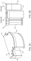
- FIG. 2A is a diagram showing a perspective view of the occupancy indicator device showing a control unit and a light indicator system enclosed within a housing, according to an exemplary embodiment.
- FIG. 2B is a diagram showing a side view of the occupancy indicator device including the control unit and the light indicator system communicatively coupled using power and control wires, according to an exemplary embodiment.
- FIG. 3 is a block diagram showing the control unit of the occupancy indicator device, according to an exemplary embodiment.
- FIG. 4 is a block diagram showing the light indicator system of the occupancy indicator device, according to an exemplary embodiment.
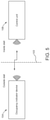
- FIG. 5 is a block diagram showing an occupancy indicator device in which the control unit and the light indicator system are physically separated, according to an exemplary embodiment.
- FIG. 6 is a block diagram showing a perspective view of the occupancy indicator device and the control unit, according to an exemplary embodiment.
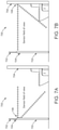
- FIG. 7A is a diagram showing a side view of a bathroom with the occupancy indicator device mounted in a first configuration in which the light indicator system is positioned on the wall outside of the bathroom and the control unit is positioned on a side of a bathroom door that faces an inside of the bathroom, according to an exemplary embodiment.
- FIG. 7B is a diagram showing a side view of the bathroom with the occupancy indicator device mounted in a second configuration in which the light indicator system is positioned on a front face of the bathroom door and the control unit is positioned on an opposite side wall of the bathroom door, according to an exemplary embodiment.
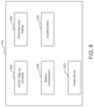
- FIG. 8 is a block diagram showing the occupancy indicator device, according to an exemplary embodiment.
- FIG. 9 is a block diagram showing the control unit of the occupancy indicator device, according to an exemplary embodiment.
- FIG. 10 shows a flow diagram to indicate occupancy of the stall, in accordance with an exemplary embodiment.
- FIG. 1A is a diagram showing a front view of a stall 101 and an occupancy indicator device 102 mounted on a door 103 of the stall 101 , according to an exemplary embodiment.
- a front view of a stall 101 and an occupancy indicator device 102 there is shown a front view of a stall 101 and an occupancy indicator device 102 .
- the stall 101 may be a bathroom stall or a washroom stall.
- the stall 101 may embody a changing room, for instance, a single user changing room or a multi-user changing room such as a family changing room.
- stall 101 may be construed as including changing rooms, washrooms, or bathrooms where more than one person can be accommodated at a given point in time or a changing room, a washroom, or a bathroom where only a single user may be accommodated at a given point in time.
- the stall 101 and a corresponding door 103 of the stall 101 in the present disclosure may hereinafter be explained in conjunction with, or in reference to, the bathroom, for example, as ‘the stall’ and as ‘the door’ respectively.
- the stall 101 such designated, or specific type of, use of the stall 101 disclosed herein is merely for illustrative purpose and explanatory in nature, and therefore, non-limiting of this disclosure.
- stalls including but not limited to, changing room(s), washrooms, or other reticulated enclosures such as restrooms containing several changing rooms, washrooms, or bathrooms, in the form of stalls that are physically separated from one another wherein each of the stalls in the reticulated enclosure may be provided with an occupancy indicator device 102 .
- the occupancy indicator device 102 is configured to be installed on top of a door 103 using a tamper proof mounting technique. For example, using rivets or nuts, bolts, and screws, such that installation and removal of the occupancy indicator device 102 does not damage the door 103 yet prevents miscreants from stealing, or tampering, the occupancy indicator device 102 .
- a tamper proof mounting technique For example, using rivets or nuts, bolts, and screws, such that installation and removal of the occupancy indicator device 102 does not damage the door 103 yet prevents miscreants from stealing, or tampering, the occupancy indicator device 102 .
- a tamper proof mounting technique For example, using rivets or nuts, bolts, and screws, such that installation and removal of the occupancy indicator device 102 does not damage the door 103 yet prevents miscreants from stealing, or tampering, the occupancy indicator device 102 .
- any damage occurs to the door 103 , for example, due to a screw hole, such damage may
- the occupancy indicator device 102 merely requires commonly known hand tools such as a screwdriver for installation, where installation would take no more than a few minutes, for example, 10 to 15 minutes, and could be accomplished by a person skilled in the art. Any air gap between the occupancy indicator device 102 and the door 103 may be reduced to a minimum to prevent, or at least minimize, a possibility of theft or vandalism.
- the occupancy indicator device 102 may be resistant to mold and rust, is easy to install, theft proof, aesthetically pleasing, and of rugged design in addition to being waterproof, or at least, water resistant, for example, the occupancy indicator device 102 may be built in compliance with resistance to water splashes, for example, IP54 to IP67.
- FIG. 1B is a diagram showing a top view of the stall 101 , according to an exemplary embodiment.
- the occupancy indicator device 102 that may be disposed at a top middle portion of the door 103 , and includes, amongst other things, a motion sensor 302 A (shown in FIG. 3 ) to detect occupancy status of the stall 101 by detecting motion therein. While the device occupancy indicator 102 is shown to be located on the middle portion of the door 103 , it would be apparent to a person of ordinary skill in the art, that the occupancy indicator device 102 may be located anywhere on the door 103 , for example, mounted at any position along a width of the top portion of the door 103 .
- FIG. 1C is a diagram showing a side view of the stall 101 , according to an exemplary embodiment.
- the occupancy indicator device 102 that may be disposed at the top portion of the door 103 so that the motion sensor 302 A is configured to detect occupancy status of the stall 101 by detecting motion of objects, for example, users of the stall 101 .
- FIG. 2A is a diagram showing a perspective view of the occupancy indicator device 102 showing a control unit 204 and a light indicator system 202 enclosed within a housing 107 , according to an exemplary embodiment.
- FIG. 2A is described in conjunction with FIGS. 1A-1C .
- the device occupancy indicator 102 that is enclosed within a housing 107 having a U-shaped bracket 109 running over the top portion of the door 103 (see FIG. 2B ).
- a width of the U-shaped bracket 109 may be approximately 1 ′′ long and 3 / 8 ′′ thick.
- the occupancy indicator device 102 includes a light indicator system 202 and a control unit 204 enclosed within the housing 107 .
- the light indicator system 202 is communicatively coupled to the control unit 204 using power and control wires that are also enclosed within the housing 107 and run internal to the U-shaped bracket 109 of the housing 107 .
- FIG. 2B is a diagram showing a side view of the occupancy indicator device 102 including the control unit 204 and the light indicator system 202 communicatively coupled using power and control wires, according to an exemplary embodiment.
- FIG. 2B is described in conjunction with FIGS. 1-2A .
- the control unit 204 is positioned on a side of the door 103 facing the inside of the stall 101 while the light indicator system 202 is positioned on the door 103 outside of the stall 101 so that a user can easily view the light indicator system 202 .
- the control unit 204 controls an operation of the light indicator system 202 .
- a profile of the light indicator system 202 may be polygonal, for example, having a quadrangular cross-section, or at least partially rounded, for example, in a substantially cylindrical, or elliptical manner so as to protrude away from the door 103 with at least a 180 -degree field of view that provides ease of viewing to the user, especially, when the user is at a skewed, or side, viewing angle to a front face of the door 103 on which the light indicator system 202 is positioned.
- a color of the light indicator system 202 is responsive to a combination of sensor inputs feeding a processor 302 D (shown in FIG. 3 ) of the control unit 204 .
- the processor 302 D is configured to execute a machine learning (ML) algorithm to determine if the stall 101 is empty or occupied.
- the light indicator system 202 may operatively support a display of at least the colors red, blue, and green.
- the color green may be lit when the stall 101 is vacant and the color red may be lit when the stall 101 is occupied.
- the light indicator system 202 may also be configured to display another color or flash a pre-determined color, for example, the red color itself at a pre-determined frequency for indicating other operational conditions such as a low-battery status, a diagnosed fault condition besides other types of operational conditions commonly known in the art.
- a number of colors and a state of the colors displayed by the light indicator system 202 may also be configured prior to installation and use depending on specific requirements of an application.
- the light indicator system 202 may be configured to display the colors red and green for standard stalls. In another instance, the light indicator system 202 may be configured to display red and blue colors for stalls that are designated for use by differently abled persons. Moreover, varying states (e.g., solid, or intermittent, for example, flashing fast, flashing slow, or switching between colors) may also be implemented for use by the light indicator system 202 for indicating different conditions of use based on sensor data while suiting one or more specific requirements of an application.
- states e.g., solid, or intermittent, for example, flashing fast, flashing slow, or switching between colors
- FIG. 3 is a block diagram showing the control unit 204 of the occupancy indicator device 102 , according to an exemplary embodiment.
- FIG. 3 is described in conjunction with FIGS. 1-2B .
- an electronics assembly 302 that is enclosed within a portion of the housing that is positioned on the side of the door 103 facing the inside of the stall 101 .
- the electronics assembly 302 includes a motion sensor 302 A, an inertial measurement unit 302 B, an ambient light sensor 302 C and the processor 302 D.
- An occupancy sensor 304 (similar to the motion sensor 302 A) is configured to detect if the stall 101 is occupied or not.
- the electronics assembly 302 further includes a set of electronic devices (not shown) mounted onto a single printed circuit card.
- the electronic devices may include, a microcontroller, a Bluetooth radio, a real time clock (RTC), and multiple sensors coupled to the door 103 .
- the multiple sensors may also include a light intensity sensor, a motion sensor, a battery life sensor, and an inertial measurement unit (IMU) sensor 302 B.
- the IMU sensor 302 B may be used to monitor the position of the door 103 .
- the electronic assembly 302 further includes an internal clock and a memory to record historical, time-stamped activity for each sensor data.
- the light intensity sensor is configured to put the system in sleep mode to extend battery life when lights of the stall 101 are off.
- the housing of the electronics assembly 302 may include arrangements or provisions for installing ambient light and motion sensors.
- such provisions may include physical openings, or openings to incorporate transparent radio frequency (RF) light sensitive materials.
- RF radio frequency
- the electronic assembly 302 may include the processor 302 D that implements a supervised ML based algorithm to make use of data captured by the sensors such as motion sensor 302 A, ambient light sensor 302 C, IMU 302 B, Passive Infrared Sensor (PIR), etc., to classify the current stall condition as “occupied” or “not occupied”.
- ML algorithms may include Support Vector Machine (SVM), Decision Trees, k-nearest neighbor, Naive Bayes, and Logistic Regression.
- an accelerometer 306 for example, an ultra-low-power 3-axis accelerometer may be used to detect the door motion and the door open/close event.
- the electronics assembly 302 may include a wireless device or a radio transceiver, also referred to as a radio module for transmitting time-stamped sensor data to other devices such as a wireless hub/mobile device/personal computer.
- the data may be sent via a wireless gateway to a cloud platform.
- the data may include information regarding when corresponding stall 101 was occupied, duration of each usage of the stall 101 , and when the corresponding stall 101 was serviced.
- the cloud platform may provide an application to be executed on the mobile device/personal computer to display current and historical data of each stall 101 .
- the cloud platform may also process time-stamped sensor data to predict and pre-alert service personnel when the stall 101 needs servicing and pass the data for integration to other cloud services.
- the user may label the control unit 204 associated with the occupancy indicator device 102 so that it may be uniquely identified.
- the application may be able to upload the control data, and display time series data showing when the stall 101 was empty and occupied.
- the application may enable the user to set the time/date window (start and stop time/date).
- the application may display the number of times the stall 101 was used in a given period (e.g., day/week/month).
- the application may also report a percentage of battery life remaining of corresponding occupancy indicator device 102 .
- the mobile application may push the data to the cloud platform for storage and remote access by corresponding building owner/landlord for further analysis and display.
- a dedicated access point that monitors all the control units (e.g., 204 ) and sends data to the cloud platform.
- the cloud platform may send a notification to a service crew when stall 101 has been used a threshold number of times and needs servicing, so that the service crew may record each time the stall 101 is serviced.
- the control unit may further be integrated to a smart building management system.
- a wireless hub portable service notifier may be provided therein to record when a service unit is in close proximity to capture when stall 101 is serviced.
- the light indicator system 202 may be configured to work in cooperation with the control unit 204 .
- the light indicator system 202 may be configured to be communicatively coupled with the control unit 204 .
- the light indicator system 202 may be communicatively coupled with the cloud platform via the wireless gateway in the electronics assembly 302 .
- the light indicator system 202 may be configured to detect change state, indicate it and send alerts/notifications to the cloud platform or a building management system or a communication device of a supervisor.
- the light indicator system 202 may transmit or send information related to the color and the state of the color indicating operational conditions. For instance, the light indicator system 202 may work in cooperation the electronics assembly 302 of the control unit 204 to determine operational conditions.
- such operating conditions may correspond to a duration of the occupancy of the stall 101 .
- the light indicator system 202 may be configured to work in cooperation with the control unit 204 to send notifications to the cloud platform or the supervisor indicating the operating condition or a change in the operating condition.
- the change in operating conditions may include a change in temperature around the stall 101 .
- the light indicator system 202 may indicate it by changing the color. Further change in operating conditions may include a status of low battery of the light indicator system 202 or a sudden change in the ambient light.
- the light indicator system 202 may indicate such changes and cooperatively work with the control unit 204 to send notifications to the cloud platform or the building management system or the supervisor.
- FIG. 4 is a block diagram showing the light indicator system 202 of the occupancy indicator device 102 , according to an exemplary embodiment.
- FIG. 4 is described in conjunction with FIGS. 1-3 .
- the light indicator system 202 that includes a DC/DC step-up converter 402 , an advanced color display 404 , and a battery compartment 406 containing replaceable batteries.
- the advanced color display 404 is configured to support, at a minimum, the colors green, and red. The color green is lit when the stall 101 is vacant and color red is lit when the stall 101 is occupied.
- the lights can be configured to flash at different rates indicating different conditions.
- the light indicator system 202 may include a speaker for an audible alarm that indicates a low-battery status or that service is required.
- the battery compartment 406 may output a voltage of 3.7V
- the DC/DC step-up converter 402 may convert the battery output to voltage levels of +5V, ⁇ 5V, +15V and ⁇ 15V.
- FIG. 5 is a block diagram showing an occupancy indicator device 104 in which the control unit 106 and the light indicator system 202 are physically separated, according to an exemplary embodiment.
- FIG. 5 is described in conjunction with FIGS. 1-4 .
- the occupancy indicator device 104 may be powered by a basic battery unit that may be mounted on the bath stall door 103 , such that the occupancy indicator device 104 is outside the stall 101 .
- the control unit 106 may be mounted on a corresponding wall, such that the control unit 106 is inside the stall 101 .
- the control unit 106 and the occupancy indicator device 104 are physically separated but a communicatively coupled via point to point or wireless mesh communication technology.
- FIG. 6 is a diagram showing a perspective view of the control unit 106 and the light indicator system 202 , according to a second embodiment of the occupancy indicator device 102 .
- FIG. 6 is described in conjunction with FIG. 5 .
- the occupancy indicator device 104 and the control unit 106 there is shown the occupancy indicator device 104 and the control unit 106 .
- the light indicator system 202 and the control unit 106 are physically separated but communicatively coupled via a wireless communication link, for example, Bluetooth, or other Internet protocols such as Local Area network (LAN), or Wi-Fi, but not limited thereto.
- LAN Local Area network
- Wi-Fi Worldwide Interoperability for Microwave Access
- control unit 106 is positioned inside the stall 101 , for example, on a back wall of the stall (as exemplarily shown in the diagrammatic side view of FIG. 7B ), a back side of the door 103 (as exemplarily shown in the diagrammatic side view of FIG. 7A ), or a sidewall of the stall 101 .
- the light indicator system 202 may be positioned on the door 103 outside of the stall 101 (as exemplarily shown in the diagrammatic side view of FIG. 7B ), or on a wall 702 supporting the door 103 (as exemplarily shown in the diagrammatic side view of FIG. 7A ) so that a user can easily view the light indicator system 202 .
- the control unit 106 controls the operation of the light indicator system 202 .
- the light indicator system 202 may be polygonal, for example, having a quadrangular cross-section, or at least partially rounded, for example, in a substantially cylindrical, or elliptical manner so as to protrude away from the door 103 with at least a 180-degree field of view that provides ease of viewing to the user, especially, when the user is at a skewed, or side, viewing angle to a front face of the door 103 on which the light indicator system 202 is positioned.
- a color of the light indicator system 202 is responsive to a combination of sensor inputs feeding the processor 302 D (shown in FIG. 3 ) of the control unit 106 .
- the processor 302 D is configured to execute a ML algorithm to determine if the stall 101 is empty or occupied.
- the light indicator system 202 may operatively support a display of at least the colors red, blue, and green.
- the color green may be lit when the stall 101 is vacant and the color red may be lit when the stall 101 is occupied.
- the light indicator system 202 may also be configured to display another color or flash a pre-determined color, for example, the red color itself at a pre-determined frequency for indicating other operational conditions such as a low-battery status, a diagnosed fault condition besides other types of operational conditions commonly known in the art.
- a number of colors and a state of the colors displayed by the light indicator system 202 may also be configured prior to installation and use depending on specific requirements of an application.
- the light indicator system 202 may be configured to display the colors red and green for standard stalls. In another instance, the light indicator system 202 may be configured to display red and blue colors for stalls that are designated for use by differently abled persons. Moreover, varying states (e.g., solid, or intermittent i.e., flashing fast, flashing slow, or switching between colors) may also be implemented for use by the light indicator system 202 for indicating different conditions of use based on sensor data while suiting one or more specific requirements of an application.
- states e.g., solid, or intermittent i.e., flashing fast, flashing slow, or switching between colors
- FIG. 7A is a diagram showing a side view of a bathroom 700 with the occupancy indicator device 104 mounted in a first configuration in which the light indicator system 202 is positioned on the wall 702 outside of the bathroom 700 and the control unit 106 is positioned on a side of a bathroom door 703 that faces an inside of the bathroom 700 , according to an exemplary embodiment.
- FIG. 7A is described in conjunction with FIGS. 5-6B .
- FIG. 7A there is shown a side view of a bathroom 700 with the occupancy indicator device 104 mounted in a first configuration in which the light indicator system 202 is positioned on a wall 702 outside the bathroom 700 and the control unit 106 is positioned on a side of the bathroom door 703 facing an inside of the bathroom 700 .
- the occupancy indicator device 104 is physically separated from the control unit 106 , they communicate via point to point communication or via a wireless mesh technology. While the occupancy indicator device 104 is shown to be located on the wall 702 , it would be apparent to a person of ordinary skill in the art, that the occupancy indicator device 104 may be located anywhere on the door 703 , for example, mounted at any position along a width of the door 703 .
- FIG. 7B is a diagram showing a side view of the bathroom 700 with the occupancy indicator device 104 mounted in a second configuration in which the light indicator system 202 is positioned on a front face of the bathroom door 703 and the control unit 106 is positioned on an opposite side wall 704 of the bathroom 700 , according to an exemplary embodiment.
- FIG. 7B is described in conjunction with FIGS. 3-4 and 5-7A . With reference to FIG.
- the occupancy indicator device 104 that may be disposed in a second configuration in which the light indicator system 202 is positioned on a front face of the bathroom door 703 i.e., a face of the bathroom door 703 facing outside the bathroom 700 and the control unit 106 is positioned on another wall 704 of the bathroom 700 for example, the back wall 704 of the bathroom 700 that faces the inside of the bathroom 700 .
- the motion sensor 302 A is configured to detect a motion of the bathroom door 703 easily and readily, while the occupancy sensor 304 is configured to detect movement of an object, for example, one or more persons in the bathroom 700 .
- the control unit 106 is positioned inside the bathroom 700 on the wall 704 .
- the light indicator system 202 and the control unit 106 are physically separated but they communicate via point to point communication or via a wireless mesh technology.
- FIG. 8 is a block diagram showing the occupancy indicator device 104 , according to an exemplary embodiment.
- FIG. 8 is described in conjunction with FIGS. 1-7B .
- the occupancy indicator device 104 that includes the DC/DC step-up converter 402 , the advanced color display 404 , and the battery compartment 406 containing replaceable batteries.
- the advanced color display 404 is configured to support, at a minimum, the colors green, and red. The color green is lit when the stall 101 is vacant and color red is lit when the stall 101 is occupied. The lights can be made to flash at different rates indicating different conditions.
- the light indicator system 202 may include a speaker for an audible alarm that indicates a low-battery status or that service is required.
- the battery compartment 406 may output a voltage of 3.7V
- the DC/DC step-up converter 402 may convert the battery output to voltage levels of +5V, ⁇ 5V, +15V and ⁇ 15V.
- the occupancy indicator device 104 may include a radio module 802 , for example, the radio transceiver with antenna that provides proxy function to represent an edge network on a digital cloud that may be implemented with one or more data processing functions to realize various artificial intelligence (AI) inference tasks.
- a radio module 802 for example, the radio transceiver with antenna that provides proxy function to represent an edge network on a digital cloud that may be implemented with one or more data processing functions to realize various artificial intelligence (AI) inference tasks.
- AI artificial intelligence
- FIG. 9 is a block diagram showing the control unit 106 , according to an exemplary embodiment.
- FIG. 9 is described in conjunction with FIGS. 1, 3, 4 and 8 .
- the electronics assembly 302 may be enclosed within a portion of the housing 107 that houses the control unit 106 and is positioned facing the inside of the stall 101 .
- the electronics assembly 302 includes the motion sensor 302 A, the inertial measurement unit 302 B, the ambient light sensor 302 C and the processor 302 D.
- the occupancy sensor 304 may include a 60 GHz Radar, or a passive Infrared (IR) sensor.
- the electronics assembly 302 may include a set of electronic devices i.e., sensors 302 A- 302 C, 304 and 306 that may be reside on a single, or multiple, printed circuit cards.
- the electronic devices may additionally include components such as, but not limited to, a microcontroller, a Bluetooth radio, a RTC, and the sensors 302 A- 302 C, 304 and 306 disclosed earlier herein.
- Examples of other devices may include, but are not limited to, a battery life sensor that may indicate an amount of electric charge remnant in a battery of the occupancy indicator device 104 and an internal clock and memory that may facilitate recording of time-stamped activity for each data output by the sensor(s) to the processor 302 D.
- control unit 104 may also include a light intensity sensor that may be configured to put the system i.e., the occupancy indicator device 104 in sleep mode, for instance—to extend battery life, when one or more lights of the stall 101 are in an OFF state.
- the housing 109 may also define openings (not shown) for installing ambient light and motion sensors therein. These openings may be physical openings, or openings that incorporate transparent RF light sensitive materials.
- the processor 302 D executes machine learning algorithms using the data that is captured by the sensors such as the motion sensor 302 A, the IMU 302 B, and the ambient light sensor 302 C to classify the current stall condition as “occupied” or “not occupied”.
- Some examples of ML algorithms include, but are not limited to, SVM, Decision Trees, k-nearest neighbor, Naive Bayes, and Logistic Regression.
- the accelerometer 306 for example, an ultra-low-power 3-axis accelerometer is used to detect the door 103 motion and the door open/close event.
- the radio module 802 of the electronics assembly 302 may include a wireless device or a wireless transceiver for transmitting time-stamped sensor data to other devices such as a mobile device or personal computer.
- the data may be sent via a wireless gateway to the digital cloud platform which in turn may transmit data to the mobile device or personal computer.
- the data may include information regarding when corresponding stall 101 was occupied, duration of each usage, and when corresponding stall 101 was serviced.
- the cloud platform may provide an application to be executed on the mobile device or personal computer to display current and historical usage and service related data of each stall 101 .
- the cloud platform may process the time-stamped data to predict and alert service personnel when the stall 101 needs servicing and pass the data for integration to the mobile device or personal computer.
- Control personnel may initialize and designate each control unit 204 so that it may be uniquely identified with a specific stall 101 , for instance, when multiple stalls are present.
- the control unit 106 and the application on the cloud platform may be able to upload the data, and display time series data showing when the stall 101 was empty and occupied.
- the application may enable the control personnel to set the time/date window (start and stop time/date).
- the application may display the number of times the stall 101 was used in a given period (e.g., day week/month).
- the application may also report a percentage of battery life remaining of corresponding occupancy indicator device 102 .
- the mobile application may push the data to the cloud platform for storage and remote access by corresponding building owner or landlord for further analysis.
- a dedicated access point that monitors all control units and sends data to the cloud platform.
- the cloud platform may send a notification to service personnel, or crew, regarding when the stall 101 has been used a threshold number of times and needs servicing, so that the service crew may record each time the stall 101 is serviced.
- the control unit 106 may further be integrated with a smart building management system.
- the control unit 106 may include a DC/DC step-up converter 402 , a color display 404 , and a battery compartment 406 containing replaceable, or rechargeable, batteries.
- the color display 404 may be configured to support, at a minimum, the colors red, green, and blue. The color green may be lit when the stall 101 is vacant and color red may be lit when the stall 101 is occupied.
- the lights of the light indicator system 202 can be made to flash at different rates indicating different conditions.
- the light indicator system 202 may also include a speaker for providing an audible alarm that indicates a low-battery status or that service is required.
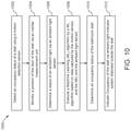
- FIG. 10 shows a flow diagram 1000 to indicate occupancy of the stall 101 , in accordance with an exemplary embodiment.
- the flow diagram 1000 is described in conjunction with FIGS. 1-9 .
- the method 1000 includes detecting an occupancy status of the stall using the motion sensor 302 A.
- the method 1000 includes monitoring a position of the door 103 of the stall 101 using the IMU 302 B.
- the method 1000 includes determining a status of ambient light within the stall 101 using the ambient light sensor 302 C.
- the method 1000 includes executing, by the processor 302 D, the ML algorithm using data captured by the motion sensor 302 A, the IMU 302 B and the ambient light sensor 302 C.
- the method 1000 includes determining an occupancy status of the stall 101 , and generating data regarding stall occupancy, duration of each usage, and when corresponding stall was serviced.
- the method 1000 includes indicating the occupancy of the stall 101 using the light indicator system 106 disposed outside the stall 101 .
- the occupancy indicator device 102 may provide a solution for monitoring the occupancy in the stall. Deployment of the occupancy indicator device 102 does not require any major form of alterations to be carried out to existing buildings, stalls, or doors, thereby being easily retrofitted onto existing structures, and therefore, reducing costs associated with installation and subsequent maintenance of the occupancy indicator device 102 . Moreover, the occupancy indicator device 102 may be implemented or deployed using low energy consumption components and technology, for example, an integrated Bluetooth Low Energy (BLE) client that may create access and communication with the cloud platform and other nearby devices.
- BLE Bluetooth Low Energy
Landscapes
- Engineering & Computer Science (AREA)
- Physics & Mathematics (AREA)
- Software Systems (AREA)
- Theoretical Computer Science (AREA)
- General Physics & Mathematics (AREA)
- Evolutionary Computation (AREA)
- Medical Informatics (AREA)
- Data Mining & Analysis (AREA)
- Computing Systems (AREA)
- General Engineering & Computer Science (AREA)
- Computer Vision & Pattern Recognition (AREA)
- Mathematical Physics (AREA)
- Artificial Intelligence (AREA)
- Electromagnetism (AREA)
- Emergency Alarm Devices (AREA)
- Alarm Systems (AREA)
Abstract
Description
- This application claims priority to and the benefit of U.S. Provisional Patent Application No. 63/053,054, filed Jul. 17, 2020, the entire disclosure of which is hereby incorporated by reference.
- The present disclosure relates to occupancy sensing and indication within a specific area such as a changing room, a single user washroom (or bathroom) stall. More specifically, the present disclosure pertains to occupancy sensing and indication within the specific area.
- Gyms, stadiums, airports, convention centers, shopping malls, and other small and large venues may have one or more stalls, for example, one or more changing room(s), single user washroom(s) or bathroom(s), family changing rooms, or even a reticulated restroom containing several washroom or bathroom stalls physically separated from one another. For using a stall, patrons may first need to attempt an opening of a door of the stall, for example, the changing room, washroom stall or bathroom stall to discern if the corresponding stall is available. For restrooms with multiple stalls, the arrangement of stalls in an elongated corridor in the restroom may make it difficult for users, who usually wait near an entrance of the restroom, to determine which stalls are vacant. In such configurations of restrooms, the occupancy status of the stall becomes even more difficult to determine as the distance from the stall increases. An empty stall may remain unoccupied, and unused, and may increase wait times for users who desire to use the stalls present in the restroom. Also, corresponding landlord and building manager is not able to remotely assess current occupancy status or capture, store and analyze historical usage and service data. Data pertaining to usage patterns of stalls may need to be analyzed to enable more efficient servicing of changing rooms, bathrooms, or washrooms as such data can help optimize, or reduce, for example, maintenance routines, for instance, janitor effort in the case of bathroom stalls or washroom stalls.
- Presently, known configurations of changing rooms, bathrooms or washrooms are unable to display locally, that is to patrons, or users, of the bathroom, the washroom, or the changing room if the corresponding stall, or type of stall, is currently occupied or not i.e., vacant, and therefore, available for use. In some configurations of such stalls, signs denoting the occupancy status of the stalls are fixed orthogonal to corresponding door faces, so there is limited visibility to users wishing to view from a skewed, or a side, viewing angle. In other configurations of such stalls, a light indicator may be suspended from the ceiling entailing, or requiring, improved dexterity on the part of the user, or patron, i.e., of the neck muscles to look up and thus makes it difficult for the user, or patron, to readily know the occupancy status of such stall. In some cases, an incorrect sign, or display, of the occupancy status may be rendered if the door is ajar and someone is still inside the stall. Also, existing configuration of stalls may not be connected via the Internet, and hence, may not capture any historical status of usage or service data.
- According to an aspect of the present disclosure, an occupancy indicator device to indicate occupancy of a stall is provided. The occupancy indicator device includes a control unit having a motion sensor configured to detect motion of a door of the stall, an inertial measurement unit (IMU) configured to monitor a position of the door, an occupancy sensor configured to detect movement of an object in the stall, and an ambient light sensor configured to determine a status of an ambient light in the stall. The motion sensor, the IMU, the oocupancy sensor and the ambient light sensor may be enclosed in a housing having a U-shaped bracket. The control unit also includes a processor that is configured to execute a Machine Learning (ML) algorithm using data captured by the motion sensor, the IMU and the ambient light sensor to determine an occupancy status of the stall and generate data pertaining to stall occupancy, duration of each usage, and when corresponding stall was serviced. The occupancy indicator device also includes a light indicator system that is disposed outside of the door and communicatively coupled to the control unit through power and control wires. A color of the light indicator system is responsive to a combination of sensor inputs feeding the ML algorithm.
- In another aspect of the present disclosure, an occupancy indicator device to indicate occupancy of a stall is provided. The occupancy indicator device includes a control unit having a motion sensor configured to detect motion of a door of the stall, an inertial measurement unit (IMU) configured to monitor a position of the door, an occupancy sensor configured to detect movement of an object in the stall, and an ambient light sensor configured to determine a status of a light in the stall. The control unit also includes a processor that is configured to execute a ML algorithm using data captured by the motion sensor, the IMU and the ambient light sensor to determine an occupancy status of the stall and generate data pertaining to stall occupancy, duration of each usage, and when corresponding stall was serviced. The occupancy indicator device also includes a light indicator system that is positioned outside of the door and in wireless communication with the control unit. A color of the light indicator system is responsive to a combination of sensor inputs feeding the ML algorithm.
- In yet another aspect of the present disclosure, a computer implemented method to indicate occupancy of a stall includes detecting an occupancy status of the stall using a motion sensor, monitoring a position of a door of the stall using an inertial measurement unit, determining a status of a light of the stall using an ambient light sensor. The method further includes executing, by a processor, a ML algorithm using data captured by the motion sensor, the IMU and the ambient light sensor. The method further includes determining, by the processor, an occupancy status of the stall, and generating, by the processor, data pertaining to stall occupancy, duration of each usage, and when corresponding stall was serviced. The method further includes indicating occupancy of the stall, via a light indicator system disposed outside of the door, wherein a color of the light indicator system is responsive to a combination of sensor inputs feeding the ML algorithm.
- The following detailed description of the preferred embodiments of the present disclosure will be better understood when read in conjunction with the appended drawings. The present disclosure is illustrated by way of example, and not limited by the accompanying figures, in which like references indicate similar elements.
-
FIG. 1A is a diagram showing a front view of a stall and an occupancy indicator device, according to an exemplary embodiment. -
FIG. 1B is a diagram showing a top view of the stall, according to an exemplary embodiment. -
FIG. 1C is a diagram showing a side view of the stall, according to an exemplary embodiment. -
FIG. 2A is a diagram showing a perspective view of the occupancy indicator device showing a control unit and a light indicator system enclosed within a housing, according to an exemplary embodiment. -
FIG. 2B is a diagram showing a side view of the occupancy indicator device including the control unit and the light indicator system communicatively coupled using power and control wires, according to an exemplary embodiment. -
FIG. 3 is a block diagram showing the control unit of the occupancy indicator device, according to an exemplary embodiment. -
FIG. 4 is a block diagram showing the light indicator system of the occupancy indicator device, according to an exemplary embodiment. -
FIG. 5 is a block diagram showing an occupancy indicator device in which the control unit and the light indicator system are physically separated, according to an exemplary embodiment. -
FIG. 6 is a block diagram showing a perspective view of the occupancy indicator device and the control unit, according to an exemplary embodiment. -
FIG. 7A is a diagram showing a side view of a bathroom with the occupancy indicator device mounted in a first configuration in which the light indicator system is positioned on the wall outside of the bathroom and the control unit is positioned on a side of a bathroom door that faces an inside of the bathroom, according to an exemplary embodiment. -
FIG. 7B is a diagram showing a side view of the bathroom with the occupancy indicator device mounted in a second configuration in which the light indicator system is positioned on a front face of the bathroom door and the control unit is positioned on an opposite side wall of the bathroom door, according to an exemplary embodiment. -
FIG. 8 is a block diagram showing the occupancy indicator device, according to an exemplary embodiment. -
FIG. 9 is a block diagram showing the control unit of the occupancy indicator device, according to an exemplary embodiment. -
FIG. 10 shows a flow diagram to indicate occupancy of the stall, in accordance with an exemplary embodiment. - The detailed description of the appended drawings is intended as a description of preferred embodiments of the present disclosure and is not intended to represent the only form in which the present disclosure may be implemented or practiced. It is to be understood that the same or equivalent functions may be accomplished by different embodiments that are intended to be encompassed within the spirit and scope of the present disclosure.
- As used in the specification and claims, the singular forms “a”, “an” and “the” include plural references unless the context clearly dictates otherwise. For example, the term “an article” may include a plurality of articles unless the context clearly dictates otherwise.
- Those with ordinary skill in the art will appreciate that elements in the figures are diagrammatically illustrated for simplicity and clarity and hence, may not be necessarily drawn to scale. For example, dimensions of some elements in the figures may be exaggerated, relative to other elements, in order to improve the understanding of the present disclosure.
- There may be additional components described in the present disclosure that are not depicted on the appended drawings. In the event, such a component is described, but not depicted in a drawing, the absence of such a component from the drawing should not be considered as an omission of such design from the specification. In fact, such omission may have been willful and deliberately carried out to prevent obscuring more pertinent details of the present disclosure whilst further simplifying and clarifying the present disclosure.
- As required, detailed embodiments of the present disclosure are disclosed herein; however, it is to be understood that the disclosed embodiments are merely exemplary of the present disclosure, which can be embodied in various forms. Therefore, specific structural and functional details disclosed herein are not to be interpreted as limiting, but merely as a basis of support for the claims and as a representative basis for teaching one skilled in the art to employ the present disclosure on virtually any appropriately designed structure, for example, on chairs in a theatre or a stadium to know occupancy status thereof. Further, the terms and phrases used herein are not intended to be limiting but rather to provide an understandable description of the present disclosure.
-
FIG. 1A is a diagram showing a front view of astall 101 and anoccupancy indicator device 102 mounted on adoor 103 of thestall 101, according to an exemplary embodiment. With reference toFIG. 1A , there is shown a front view of astall 101 and anoccupancy indicator device 102. For example, thestall 101 may be a bathroom stall or a washroom stall. In yet another example, thestall 101 may embody a changing room, for instance, a single user changing room or a multi-user changing room such as a family changing room. In the present disclosure, theterm stall 101 may be construed as including changing rooms, washrooms, or bathrooms where more than one person can be accommodated at a given point in time or a changing room, a washroom, or a bathroom where only a single user may be accommodated at a given point in time. - In an embodiment, the
stall 101 and acorresponding door 103 of thestall 101 in the present disclosure may hereinafter be explained in conjunction with, or in reference to, the bathroom, for example, as ‘the stall’ and as ‘the door’ respectively. However, such designated, or specific type of, use of thestall 101 disclosed herein is merely for illustrative purpose and explanatory in nature, and therefore, non-limiting of this disclosure. Persons skilled in the art will acknowledge that the present disclosure can be similarly applied to other types of stalls, including but not limited to, changing room(s), washrooms, or other reticulated enclosures such as restrooms containing several changing rooms, washrooms, or bathrooms, in the form of stalls that are physically separated from one another wherein each of the stalls in the reticulated enclosure may be provided with anoccupancy indicator device 102. - In an embodiment, the
occupancy indicator device 102 is configured to be installed on top of adoor 103 using a tamper proof mounting technique. For example, using rivets or nuts, bolts, and screws, such that installation and removal of theoccupancy indicator device 102 does not damage thedoor 103 yet prevents miscreants from stealing, or tampering, theoccupancy indicator device 102. During installation, if any damage occurs to thedoor 103, for example, due to a screw hole, such damage may be minimal, invisible, and easily repaired so that a new door does not have to be procured for subsequent use of thestall 101 as a whole or thedoor 103 alone. Theoccupancy indicator device 102 merely requires commonly known hand tools such as a screwdriver for installation, where installation would take no more than a few minutes, for example, 10 to 15 minutes, and could be accomplished by a person skilled in the art. Any air gap between theoccupancy indicator device 102 and thedoor 103 may be reduced to a minimum to prevent, or at least minimize, a possibility of theft or vandalism. In production, theoccupancy indicator device 102 may be resistant to mold and rust, is easy to install, theft proof, aesthetically pleasing, and of rugged design in addition to being waterproof, or at least, water resistant, for example, theoccupancy indicator device 102 may be built in compliance with resistance to water splashes, for example, IP54 to IP67. -
FIG. 1B is a diagram showing a top view of thestall 101, according to an exemplary embodiment. With reference toFIG. 1B , there is shown theoccupancy indicator device 102 that may be disposed at a top middle portion of thedoor 103, and includes, amongst other things, amotion sensor 302A (shown inFIG. 3 ) to detect occupancy status of thestall 101 by detecting motion therein. While thedevice occupancy indicator 102 is shown to be located on the middle portion of thedoor 103, it would be apparent to a person of ordinary skill in the art, that theoccupancy indicator device 102 may be located anywhere on thedoor 103, for example, mounted at any position along a width of the top portion of thedoor 103. -
FIG. 1C is a diagram showing a side view of thestall 101, according to an exemplary embodiment. With reference toFIG. 1C , there is shown theoccupancy indicator device 102 that may be disposed at the top portion of thedoor 103 so that themotion sensor 302A is configured to detect occupancy status of thestall 101 by detecting motion of objects, for example, users of thestall 101. -
FIG. 2A is a diagram showing a perspective view of theoccupancy indicator device 102 showing acontrol unit 204 and alight indicator system 202 enclosed within ahousing 107, according to an exemplary embodiment.FIG. 2A is described in conjunction withFIGS. 1A-1C . With reference toFIG. 2A , there is shown thedevice occupancy indicator 102 that is enclosed within ahousing 107 having aU-shaped bracket 109 running over the top portion of the door 103 (seeFIG. 2B ). For example, a width of theU-shaped bracket 109 may be approximately 1″ long and 3/8″ thick. In an embodiment, theoccupancy indicator device 102 includes alight indicator system 202 and acontrol unit 204 enclosed within thehousing 107. Further, thelight indicator system 202 is communicatively coupled to thecontrol unit 204 using power and control wires that are also enclosed within thehousing 107 and run internal to theU-shaped bracket 109 of thehousing 107. -
FIG. 2B is a diagram showing a side view of theoccupancy indicator device 102 including thecontrol unit 204 and thelight indicator system 202 communicatively coupled using power and control wires, according to an exemplary embodiment.FIG. 2B is described in conjunction withFIGS. 1-2A . With reference toFIG. 2B , thecontrol unit 204 is positioned on a side of thedoor 103 facing the inside of thestall 101 while thelight indicator system 202 is positioned on thedoor 103 outside of thestall 101 so that a user can easily view thelight indicator system 202. Thecontrol unit 204 controls an operation of thelight indicator system 202. - In an embodiment, a profile of the
light indicator system 202 may be polygonal, for example, having a quadrangular cross-section, or at least partially rounded, for example, in a substantially cylindrical, or elliptical manner so as to protrude away from thedoor 103 with at least a 180-degree field of view that provides ease of viewing to the user, especially, when the user is at a skewed, or side, viewing angle to a front face of thedoor 103 on which thelight indicator system 202 is positioned. Moreover, a color of thelight indicator system 202 is responsive to a combination of sensor inputs feeding aprocessor 302D (shown inFIG. 3 ) of thecontrol unit 204. Theprocessor 302D is configured to execute a machine learning (ML) algorithm to determine if thestall 101 is empty or occupied. - In an embodiment, the
light indicator system 202 may operatively support a display of at least the colors red, blue, and green. In an example, the color green may be lit when thestall 101 is vacant and the color red may be lit when thestall 101 is occupied. Thelight indicator system 202 may also be configured to display another color or flash a pre-determined color, for example, the red color itself at a pre-determined frequency for indicating other operational conditions such as a low-battery status, a diagnosed fault condition besides other types of operational conditions commonly known in the art. Moreover, a number of colors and a state of the colors displayed by thelight indicator system 202 may also be configured prior to installation and use depending on specific requirements of an application. For example, thelight indicator system 202 may be configured to display the colors red and green for standard stalls. In another instance, thelight indicator system 202 may be configured to display red and blue colors for stalls that are designated for use by differently abled persons. Moreover, varying states (e.g., solid, or intermittent, for example, flashing fast, flashing slow, or switching between colors) may also be implemented for use by thelight indicator system 202 for indicating different conditions of use based on sensor data while suiting one or more specific requirements of an application. -
FIG. 3 is a block diagram showing thecontrol unit 204 of theoccupancy indicator device 102, according to an exemplary embodiment.FIG. 3 is described in conjunction withFIGS. 1-2B . With reference toFIG. 3 , there is shown anelectronics assembly 302 that is enclosed within a portion of the housing that is positioned on the side of thedoor 103 facing the inside of thestall 101. Theelectronics assembly 302 includes amotion sensor 302A, aninertial measurement unit 302B, an ambientlight sensor 302C and theprocessor 302D. An occupancy sensor 304 (similar to themotion sensor 302A) is configured to detect if thestall 101 is occupied or not. In an embodiment, theelectronics assembly 302 further includes a set of electronic devices (not shown) mounted onto a single printed circuit card. For example, the electronic devices may include, a microcontroller, a Bluetooth radio, a real time clock (RTC), and multiple sensors coupled to thedoor 103. Examples of the multiple sensors may also include a light intensity sensor, a motion sensor, a battery life sensor, and an inertial measurement unit (IMU)sensor 302B. TheIMU sensor 302B may be used to monitor the position of thedoor 103. Theelectronic assembly 302 further includes an internal clock and a memory to record historical, time-stamped activity for each sensor data. The light intensity sensor is configured to put the system in sleep mode to extend battery life when lights of thestall 101 are off. In an embodiment, the housing of theelectronics assembly 302 may include arrangements or provisions for installing ambient light and motion sensors. For example, such provisions may include physical openings, or openings to incorporate transparent radio frequency (RF) light sensitive materials. - In an embodiment, the
electronic assembly 302 may include theprocessor 302D that implements a supervised ML based algorithm to make use of data captured by the sensors such asmotion sensor 302A, ambientlight sensor 302C,IMU 302B, Passive Infrared Sensor (PIR), etc., to classify the current stall condition as “occupied” or “not occupied”. Examples of ML algorithms may include Support Vector Machine (SVM), Decision Trees, k-nearest neighbor, Naive Bayes, and Logistic Regression. In an embodiment, anaccelerometer 306, for example, an ultra-low-power 3-axis accelerometer may be used to detect the door motion and the door open/close event. - In an embodiment, the
electronics assembly 302 may include a wireless device or a radio transceiver, also referred to as a radio module for transmitting time-stamped sensor data to other devices such as a wireless hub/mobile device/personal computer. The data may be sent via a wireless gateway to a cloud platform. The data may include information regarding when correspondingstall 101 was occupied, duration of each usage of thestall 101, and when thecorresponding stall 101 was serviced. The cloud platform may provide an application to be executed on the mobile device/personal computer to display current and historical data of eachstall 101. The cloud platform may also process time-stamped sensor data to predict and pre-alert service personnel when thestall 101 needs servicing and pass the data for integration to other cloud services. The user, for example, control personnel, or service crew, may label thecontrol unit 204 associated with theoccupancy indicator device 102 so that it may be uniquely identified. When within range of thecontrol unit 204, the application may be able to upload the control data, and display time series data showing when thestall 101 was empty and occupied. The application may enable the user to set the time/date window (start and stop time/date). The application may display the number of times thestall 101 was used in a given period (e.g., day/week/month). The application may also report a percentage of battery life remaining of correspondingoccupancy indicator device 102. - In an embodiment, the mobile application may push the data to the cloud platform for storage and remote access by corresponding building owner/landlord for further analysis and display. In another embodiment, there may be provided a dedicated access point that monitors all the control units (e.g., 204) and sends data to the cloud platform. The cloud platform may send a notification to a service crew when
stall 101 has been used a threshold number of times and needs servicing, so that the service crew may record each time thestall 101 is serviced. The control unit may further be integrated to a smart building management system. Also, a wireless hub portable service notifier may be provided therein to record when a service unit is in close proximity to capture whenstall 101 is serviced. - In an embodiment, the
light indicator system 202 may be configured to work in cooperation with thecontrol unit 204. Thelight indicator system 202 may be configured to be communicatively coupled with thecontrol unit 204. Thelight indicator system 202 may be communicatively coupled with the cloud platform via the wireless gateway in theelectronics assembly 302. Thelight indicator system 202 may be configured to detect change state, indicate it and send alerts/notifications to the cloud platform or a building management system or a communication device of a supervisor. In an embodiment, thelight indicator system 202 may transmit or send information related to the color and the state of the color indicating operational conditions. For instance, thelight indicator system 202 may work in cooperation theelectronics assembly 302 of thecontrol unit 204 to determine operational conditions. For example, such operating conditions may correspond to a duration of the occupancy of thestall 101. When thestall 101 is occupied for a longer duration than that of a predetermined threshold value, thelight indicator system 202 may be configured to work in cooperation with thecontrol unit 204 to send notifications to the cloud platform or the supervisor indicating the operating condition or a change in the operating condition. The change in operating conditions may include a change in temperature around thestall 101. For instance, when theelectronics assembly 302 in thecontrol unit 204 sense that the temperature around thestall 101 is unusual and outside a specific range, thelight indicator system 202 may indicate it by changing the color. Further change in operating conditions may include a status of low battery of thelight indicator system 202 or a sudden change in the ambient light. In an embodiment, thelight indicator system 202 may indicate such changes and cooperatively work with thecontrol unit 204 to send notifications to the cloud platform or the building management system or the supervisor. -
FIG. 4 is a block diagram showing thelight indicator system 202 of theoccupancy indicator device 102, according to an exemplary embodiment.FIG. 4 is described in conjunction withFIGS. 1-3 . With reference toFIG. 4 , there is shown thelight indicator system 202 that includes a DC/DC step-upconverter 402, anadvanced color display 404, and abattery compartment 406 containing replaceable batteries. Theadvanced color display 404 is configured to support, at a minimum, the colors green, and red. The color green is lit when thestall 101 is vacant and color red is lit when thestall 101 is occupied. The lights can be configured to flash at different rates indicating different conditions. Thelight indicator system 202 may include a speaker for an audible alarm that indicates a low-battery status or that service is required. In an example, thebattery compartment 406 may output a voltage of 3.7V, and the DC/DC step-upconverter 402 may convert the battery output to voltage levels of +5V, −5V, +15V and −15V. -
FIG. 5 is a block diagram showing anoccupancy indicator device 104 in which thecontrol unit 106 and thelight indicator system 202 are physically separated, according to an exemplary embodiment.FIG. 5 is described in conjunction withFIGS. 1-4 . With reference toFIG. 5 , there is shown a second embodiment of theoccupancy indicator device 104. Theoccupancy indicator device 104 may be powered by a basic battery unit that may be mounted on thebath stall door 103, such that theoccupancy indicator device 104 is outside thestall 101. Thecontrol unit 106 may be mounted on a corresponding wall, such that thecontrol unit 106 is inside thestall 101. In the second embodiment, thecontrol unit 106 and theoccupancy indicator device 104 are physically separated but a communicatively coupled via point to point or wireless mesh communication technology. -
FIG. 6 is a diagram showing a perspective view of thecontrol unit 106 and thelight indicator system 202, according to a second embodiment of theoccupancy indicator device 102.FIG. 6 is described in conjunction withFIG. 5 . With reference toFIG. 6 , there is shown theoccupancy indicator device 104 and thecontrol unit 106. In this embodiment of theoccupancy indicator device 104, thelight indicator system 202 and thecontrol unit 106 are physically separated but communicatively coupled via a wireless communication link, for example, Bluetooth, or other Internet protocols such as Local Area network (LAN), or Wi-Fi, but not limited thereto. Further, thecontrol unit 106 is positioned inside thestall 101, for example, on a back wall of the stall (as exemplarily shown in the diagrammatic side view ofFIG. 7B ), a back side of the door 103 (as exemplarily shown in the diagrammatic side view ofFIG. 7A ), or a sidewall of thestall 101. Furthermore, thelight indicator system 202 may be positioned on thedoor 103 outside of the stall 101 (as exemplarily shown in the diagrammatic side view ofFIG. 7B ), or on awall 702 supporting the door 103 (as exemplarily shown in the diagrammatic side view ofFIG. 7A ) so that a user can easily view thelight indicator system 202. As disclosed earlier herein, thecontrol unit 106 controls the operation of thelight indicator system 202. - In an embodiment, the
light indicator system 202 may be polygonal, for example, having a quadrangular cross-section, or at least partially rounded, for example, in a substantially cylindrical, or elliptical manner so as to protrude away from thedoor 103 with at least a 180-degree field of view that provides ease of viewing to the user, especially, when the user is at a skewed, or side, viewing angle to a front face of thedoor 103 on which thelight indicator system 202 is positioned. Moreover, a color of thelight indicator system 202 is responsive to a combination of sensor inputs feeding theprocessor 302D (shown inFIG. 3 ) of thecontrol unit 106. Theprocessor 302D is configured to execute a ML algorithm to determine if thestall 101 is empty or occupied. - In an embodiment, the
light indicator system 202 may operatively support a display of at least the colors red, blue, and green. In an example, the color green may be lit when thestall 101 is vacant and the color red may be lit when thestall 101 is occupied. Thelight indicator system 202 may also be configured to display another color or flash a pre-determined color, for example, the red color itself at a pre-determined frequency for indicating other operational conditions such as a low-battery status, a diagnosed fault condition besides other types of operational conditions commonly known in the art. Moreover, a number of colors and a state of the colors displayed by thelight indicator system 202 may also be configured prior to installation and use depending on specific requirements of an application. For example, thelight indicator system 202 may be configured to display the colors red and green for standard stalls. In another instance, thelight indicator system 202 may be configured to display red and blue colors for stalls that are designated for use by differently abled persons. Moreover, varying states (e.g., solid, or intermittent i.e., flashing fast, flashing slow, or switching between colors) may also be implemented for use by thelight indicator system 202 for indicating different conditions of use based on sensor data while suiting one or more specific requirements of an application. -
FIG. 7A is a diagram showing a side view of abathroom 700 with theoccupancy indicator device 104 mounted in a first configuration in which thelight indicator system 202 is positioned on thewall 702 outside of thebathroom 700 and thecontrol unit 106 is positioned on a side of abathroom door 703 that faces an inside of thebathroom 700, according to an exemplary embodiment.FIG. 7A is described in conjunction withFIGS. 5-6B . With reference toFIG. 7A , there is shown a side view of abathroom 700 with theoccupancy indicator device 104 mounted in a first configuration in which thelight indicator system 202 is positioned on awall 702 outside thebathroom 700 and thecontrol unit 106 is positioned on a side of thebathroom door 703 facing an inside of thebathroom 700. In an embodiment, although theoccupancy indicator device 104 is physically separated from thecontrol unit 106, they communicate via point to point communication or via a wireless mesh technology. While theoccupancy indicator device 104 is shown to be located on thewall 702, it would be apparent to a person of ordinary skill in the art, that theoccupancy indicator device 104 may be located anywhere on thedoor 703, for example, mounted at any position along a width of thedoor 703. -
FIG. 7B is a diagram showing a side view of thebathroom 700 with theoccupancy indicator device 104 mounted in a second configuration in which thelight indicator system 202 is positioned on a front face of thebathroom door 703 and thecontrol unit 106 is positioned on anopposite side wall 704 of thebathroom 700, according to an exemplary embodiment.FIG. 7B is described in conjunction withFIGS. 3-4 and 5-7A . With reference toFIG. 7B , there is shown that theoccupancy indicator device 104 that may be disposed in a second configuration in which thelight indicator system 202 is positioned on a front face of thebathroom door 703 i.e., a face of thebathroom door 703 facing outside thebathroom 700 and thecontrol unit 106 is positioned on anotherwall 704 of thebathroom 700 for example, theback wall 704 of thebathroom 700 that faces the inside of thebathroom 700. In an embodiment, themotion sensor 302A is configured to detect a motion of thebathroom door 703 easily and readily, while theoccupancy sensor 304 is configured to detect movement of an object, for example, one or more persons in thebathroom 700. In an embodiment, thecontrol unit 106 is positioned inside thebathroom 700 on thewall 704. As disclosed earlier herein and as shown in the views of 7A-7B, thelight indicator system 202 and thecontrol unit 106 are physically separated but they communicate via point to point communication or via a wireless mesh technology. -
FIG. 8 is a block diagram showing theoccupancy indicator device 104, according to an exemplary embodiment.FIG. 8 is described in conjunction withFIGS. 1-7B . With reference toFIG. 8 , there is shown theoccupancy indicator device 104 that includes the DC/DC step-upconverter 402, theadvanced color display 404, and thebattery compartment 406 containing replaceable batteries. Theadvanced color display 404 is configured to support, at a minimum, the colors green, and red. The color green is lit when thestall 101 is vacant and color red is lit when thestall 101 is occupied. The lights can be made to flash at different rates indicating different conditions. Thelight indicator system 202 may include a speaker for an audible alarm that indicates a low-battery status or that service is required. In an embodiment, thebattery compartment 406 may output a voltage of 3.7V, and the DC/DC step-upconverter 402 may convert the battery output to voltage levels of +5V, −5V, +15V and −15V. - In an embodiment, the
occupancy indicator device 104 may include aradio module 802, for example, the radio transceiver with antenna that provides proxy function to represent an edge network on a digital cloud that may be implemented with one or more data processing functions to realize various artificial intelligence (AI) inference tasks. -
FIG. 9 is a block diagram showing thecontrol unit 106, according to an exemplary embodiment.FIG. 9 is described in conjunction withFIGS. 1, 3, 4 and 8 . Theelectronics assembly 302 may be enclosed within a portion of thehousing 107 that houses thecontrol unit 106 and is positioned facing the inside of thestall 101. Theelectronics assembly 302 includes themotion sensor 302A, theinertial measurement unit 302B, the ambientlight sensor 302C and theprocessor 302D. Theoccupancy sensor 304 may include a 60 GHz Radar, or a passive Infrared (IR) sensor. In an embodiment, theelectronics assembly 302 may include a set of electronic devices i.e.,sensors 302A-302C, 304 and 306 that may be reside on a single, or multiple, printed circuit cards. the electronic devices may additionally include components such as, but not limited to, a microcontroller, a Bluetooth radio, a RTC, and thesensors 302A-302C, 304 and 306 disclosed earlier herein. Examples of other devices may include, but are not limited to, a battery life sensor that may indicate an amount of electric charge remnant in a battery of theoccupancy indicator device 104 and an internal clock and memory that may facilitate recording of time-stamped activity for each data output by the sensor(s) to theprocessor 302D. Additionally, or optionally, thecontrol unit 104 may also include a light intensity sensor that may be configured to put the system i.e., theoccupancy indicator device 104 in sleep mode, for instance—to extend battery life, when one or more lights of thestall 101 are in an OFF state. In an embodiment of the present disclosure, thehousing 109 may also define openings (not shown) for installing ambient light and motion sensors therein. These openings may be physical openings, or openings that incorporate transparent RF light sensitive materials. - In an embodiment, the
processor 302D executes machine learning algorithms using the data that is captured by the sensors such as themotion sensor 302A, theIMU 302B, and the ambientlight sensor 302C to classify the current stall condition as “occupied” or “not occupied”. Some examples of ML algorithms include, but are not limited to, SVM, Decision Trees, k-nearest neighbor, Naive Bayes, and Logistic Regression. In an embodiment, theaccelerometer 306, for example, an ultra-low-power 3-axis accelerometer is used to detect thedoor 103 motion and the door open/close event. - In an embodiment, the
radio module 802 of theelectronics assembly 302 may include a wireless device or a wireless transceiver for transmitting time-stamped sensor data to other devices such as a mobile device or personal computer. The data may be sent via a wireless gateway to the digital cloud platform which in turn may transmit data to the mobile device or personal computer. The data may include information regarding when correspondingstall 101 was occupied, duration of each usage, and when correspondingstall 101 was serviced. The cloud platform may provide an application to be executed on the mobile device or personal computer to display current and historical usage and service related data of eachstall 101. The cloud platform may process the time-stamped data to predict and alert service personnel when thestall 101 needs servicing and pass the data for integration to the mobile device or personal computer. Control personnel may initialize and designate eachcontrol unit 204 so that it may be uniquely identified with aspecific stall 101, for instance, when multiple stalls are present. Thecontrol unit 106 and the application on the cloud platform may be able to upload the data, and display time series data showing when thestall 101 was empty and occupied. The application may enable the control personnel to set the time/date window (start and stop time/date). The application may display the number of times thestall 101 was used in a given period (e.g., day week/month). The application may also report a percentage of battery life remaining of correspondingoccupancy indicator device 102. - In an embodiment of the present disclosure, the mobile application may push the data to the cloud platform for storage and remote access by corresponding building owner or landlord for further analysis. In another embodiment of the present disclosure, there may be provided a dedicated access point that monitors all control units and sends data to the cloud platform. The cloud platform may send a notification to service personnel, or crew, regarding when the
stall 101 has been used a threshold number of times and needs servicing, so that the service crew may record each time thestall 101 is serviced. Thecontrol unit 106 may further be integrated with a smart building management system. - In an embodiment, the
control unit 106 may include a DC/DC step-upconverter 402, acolor display 404, and abattery compartment 406 containing replaceable, or rechargeable, batteries. Thecolor display 404 may be configured to support, at a minimum, the colors red, green, and blue. The color green may be lit when thestall 101 is vacant and color red may be lit when thestall 101 is occupied. The lights of thelight indicator system 202 can be made to flash at different rates indicating different conditions. Thelight indicator system 202 may also include a speaker for providing an audible alarm that indicates a low-battery status or that service is required. -
FIG. 10 shows a flow diagram 1000 to indicate occupancy of thestall 101, in accordance with an exemplary embodiment. The flow diagram 1000 is described in conjunction withFIGS. 1-9 . As shown, atstep 1002, themethod 1000 includes detecting an occupancy status of the stall using themotion sensor 302A. Atstep 1004, themethod 1000 includes monitoring a position of thedoor 103 of thestall 101 using theIMU 302B. Atstep 1006, themethod 1000 includes determining a status of ambient light within thestall 101 using the ambientlight sensor 302C. Atstep 1008, themethod 1000 includes executing, by theprocessor 302D, the ML algorithm using data captured by themotion sensor 302A, theIMU 302B and the ambientlight sensor 302C. Atstep 1010, themethod 1000 includes determining an occupancy status of thestall 101, and generating data regarding stall occupancy, duration of each usage, and when corresponding stall was serviced. Atstep 1012, themethod 1000 includes indicating the occupancy of thestall 101 using thelight indicator system 106 disposed outside thestall 101. - In embodiments herein, the
occupancy indicator device 102 may provide a solution for monitoring the occupancy in the stall. Deployment of theoccupancy indicator device 102 does not require any major form of alterations to be carried out to existing buildings, stalls, or doors, thereby being easily retrofitted onto existing structures, and therefore, reducing costs associated with installation and subsequent maintenance of theoccupancy indicator device 102. Moreover, theoccupancy indicator device 102 may be implemented or deployed using low energy consumption components and technology, for example, an integrated Bluetooth Low Energy (BLE) client that may create access and communication with the cloud platform and other nearby devices. - A person having ordinary skill in the art will appreciate that embodiments of the disclosed subject matter can be practiced with various computer system configurations, including multi-core multiprocessor systems, minicomputers, mainframe computers, computers linked or clustered with distributed functions, as well as pervasive or miniature computers that may be embedded into virtually any device. For instance, at least one processor and a memory may be used to implement the above described embodiments. Further, the operations may be described as a sequential process; however, some of the operations may in fact be performed in parallel, concurrently, and/or in a distributed environment, and with program code stored locally or remotely for access by single or multiprocessor machines. In addition, in some embodiments the order of operations may be rearranged without deviating from the scope of present disclosure. While various embodiments of the present disclosure have been illustrated and described, it will be clear that the present disclosure is not limited to these embodiments only. Numerous modifications, changes, variations, substitutions, and equivalents will be apparent to those skilled in the art, without departing from the spirit and scope of the present disclosure, as described in the claims.
Claims (20)
Priority Applications (1)
| Application Number | Priority Date | Filing Date | Title |
|---|---|---|---|
| US17/374,209 US20220020249A1 (en) | 2020-07-17 | 2021-07-13 | Occupancy indicator device |
Applications Claiming Priority (2)
| Application Number | Priority Date | Filing Date | Title |
|---|---|---|---|
| US202063053054P | 2020-07-17 | 2020-07-17 | |
| US17/374,209 US20220020249A1 (en) | 2020-07-17 | 2021-07-13 | Occupancy indicator device |
Publications (1)
| Publication Number | Publication Date |
|---|---|
| US20220020249A1 true US20220020249A1 (en) | 2022-01-20 |
Family
ID=79293501
Family Applications (1)
| Application Number | Title | Priority Date | Filing Date |
|---|---|---|---|
| US17/374,209 Abandoned US20220020249A1 (en) | 2020-07-17 | 2021-07-13 | Occupancy indicator device |
Country Status (1)
| Country | Link |
|---|---|
| US (1) | US20220020249A1 (en) |
Cited By (6)
| Publication number | Priority date | Publication date | Assignee | Title |
|---|---|---|---|---|
| US20220254235A1 (en) * | 2021-02-05 | 2022-08-11 | Ricky Bender | Wireless Mailbox Notification System |
| US11488457B2 (en) | 2020-06-08 | 2022-11-01 | Zurn Industries, Llc | Cloud-connected occupancy lights and status indication |
| US11514679B1 (en) | 2022-02-18 | 2022-11-29 | Zurn Industries, Llc | Smart method for noise rejection in spatial human detection systems for a cloud connected occupancy sensing network |
| US11543791B1 (en) * | 2022-02-10 | 2023-01-03 | Zurn Industries, Llc | Determining operations for a smart fixture based on an area status |
| US11555734B1 (en) | 2022-02-18 | 2023-01-17 | Zurn Industries, Llc | Smart and cloud connected detection mechanism and real-time internet of things (IoT) system management |
| US11776260B2 (en) | 2020-12-14 | 2023-10-03 | Whiffaway Ltd | Facility occupancy detection with thermal grid sensor |
Citations (5)
| Publication number | Priority date | Publication date | Assignee | Title |
|---|---|---|---|---|
| US20170122005A1 (en) * | 2014-02-20 | 2017-05-04 | Modus Systems, Inc. | Restroom stall occupancy indicator system |
| US20210097859A1 (en) * | 2018-05-02 | 2021-04-01 | Lyft, Inc. | Monitoring ambient light for object detection |
| US20210383658A1 (en) * | 2020-06-08 | 2021-12-09 | Zurn Industries, Llc | Cloud-connected occupancy lights and status indication |
| US20220191984A1 (en) * | 2020-12-14 | 2022-06-16 | Zurn Industries, Llc | Facility occupancy detection with thermal grid sensor |
| US11543791B1 (en) * | 2022-02-10 | 2023-01-03 | Zurn Industries, Llc | Determining operations for a smart fixture based on an area status |
-
2021
- 2021-07-13 US US17/374,209 patent/US20220020249A1/en not_active Abandoned
Patent Citations (5)
| Publication number | Priority date | Publication date | Assignee | Title |
|---|---|---|---|---|
| US20170122005A1 (en) * | 2014-02-20 | 2017-05-04 | Modus Systems, Inc. | Restroom stall occupancy indicator system |
| US20210097859A1 (en) * | 2018-05-02 | 2021-04-01 | Lyft, Inc. | Monitoring ambient light for object detection |
| US20210383658A1 (en) * | 2020-06-08 | 2021-12-09 | Zurn Industries, Llc | Cloud-connected occupancy lights and status indication |
| US20220191984A1 (en) * | 2020-12-14 | 2022-06-16 | Zurn Industries, Llc | Facility occupancy detection with thermal grid sensor |
| US11543791B1 (en) * | 2022-02-10 | 2023-01-03 | Zurn Industries, Llc | Determining operations for a smart fixture based on an area status |
Cited By (8)
| Publication number | Priority date | Publication date | Assignee | Title |
|---|---|---|---|---|
| US11488457B2 (en) | 2020-06-08 | 2022-11-01 | Zurn Industries, Llc | Cloud-connected occupancy lights and status indication |
| US11847905B2 (en) | 2020-06-08 | 2023-12-19 | Zurn Industries, Llc | Cloud-connected occupancy lights and status indication |
| US11776260B2 (en) | 2020-12-14 | 2023-10-03 | Whiffaway Ltd | Facility occupancy detection with thermal grid sensor |
| US20220254235A1 (en) * | 2021-02-05 | 2022-08-11 | Ricky Bender | Wireless Mailbox Notification System |
| US11455871B2 (en) * | 2021-02-05 | 2022-09-27 | Ricky Bender | Wireless mailbox notification system |
| US11543791B1 (en) * | 2022-02-10 | 2023-01-03 | Zurn Industries, Llc | Determining operations for a smart fixture based on an area status |
| US11514679B1 (en) | 2022-02-18 | 2022-11-29 | Zurn Industries, Llc | Smart method for noise rejection in spatial human detection systems for a cloud connected occupancy sensing network |
| US11555734B1 (en) | 2022-02-18 | 2023-01-17 | Zurn Industries, Llc | Smart and cloud connected detection mechanism and real-time internet of things (IoT) system management |
Similar Documents
| Publication | Publication Date | Title |
|---|---|---|
| US20220020249A1 (en) | Occupancy indicator device | |
| US10838447B2 (en) | Method and apparatus for providing energy device and system status | |
| US8456305B2 (en) | Redundant security system | |
| US20160348398A1 (en) | Door improvements and data mining via accelerometer and magnetometer electronic component | |
| US11153945B1 (en) | Facility occupancy detection with thermal grid sensor | |
| CN110800273A (en) | Virtual sensor system | |
| US8269626B2 (en) | Perimeter alarm monitoring system | |
| CN101128855A (en) | Systems and methods for providing victim location information during an emergency situation | |
| US10127782B1 (en) | Configurable sensor | |
| US20130300564A1 (en) | Method and apparatus for providing security device and system status | |
| US20210158048A1 (en) | Image-based abnormal event detection | |
| CN105046883A (en) | Monitoring and alarming system and method | |
| CN109613299A (en) | Viberation detector, method, intelligent door lock and system | |
| JP2014044474A (en) | Private room use state display system, and private room use state display program | |
| US20210182765A1 (en) | Guard tour tracking | |
| US11417102B1 (en) | Anomalous path detection within cameras' fields of view | |
| CN210295367U (en) | Rotatable earthquake sensing audible and visual alarm | |
| CN115718445B (en) | Intelligent Internet of things management system suitable for museum | |
| US10255787B1 (en) | Magnetic sensor batteries | |
| US20210350680A1 (en) | Tamper detection using smart security fasteners | |
| EP4014213B1 (en) | Notification apparatus | |
| CN108601183A (en) | Beacon monitors system and method | |
| EP1172780B1 (en) | Abnormal condition detecting system detecting abnormal condition of user at residence | |
| JPH1061273A (en) | Guard system for sliding door | |
| EP3729350B1 (en) | A battery-operated monitoring device, system and method |
Legal Events
| Date | Code | Title | Description |
|---|---|---|---|
| AS | Assignment |
Owner name: LUYS SYSTEMS INC., CALIFORNIA Free format text: ASSIGNMENT OF ASSIGNORS INTEREST;ASSIGNOR:CASTELLANO, DANIEL;REEL/FRAME:056838/0536 Effective date: 20210712 |
|
| STPP | Information on status: patent application and granting procedure in general |
Free format text: DOCKETED NEW CASE - READY FOR EXAMINATION |
|
| AS | Assignment |
Owner name: CHANIAN, THOMAS, CALIFORNIA Free format text: ASSIGNMENT OF ASSIGNORS INTEREST;ASSIGNOR:LUYS SYSTEMS INC.;REEL/FRAME:062530/0157 Effective date: 20230130 Owner name: CASTELLANO, DANIEL, CALIFORNIA Free format text: ASSIGNMENT OF ASSIGNORS INTEREST;ASSIGNOR:LUYS SYSTEMS INC.;REEL/FRAME:062530/0157 Effective date: 20230130 |
|
| STPP | Information on status: patent application and granting procedure in general |
Free format text: NON FINAL ACTION MAILED |
|
| STCB | Information on status: application discontinuation |
Free format text: ABANDONED -- FAILURE TO RESPOND TO AN OFFICE ACTION |