US11656325B2 - Methods and apparatus to realize scalable antenna arrays with large aperture - Google Patents
Methods and apparatus to realize scalable antenna arrays with large aperture Download PDFInfo
- Publication number
- US11656325B2 US11656325B2 US16/955,757 US201816955757A US11656325B2 US 11656325 B2 US11656325 B2 US 11656325B2 US 201816955757 A US201816955757 A US 201816955757A US 11656325 B2 US11656325 B2 US 11656325B2
- Authority
- US
- United States
- Prior art keywords
- module
- radar
- correction
- radar module
- phase
- Prior art date
- Legal status (The legal status is an assumption and is not a legal conclusion. Google has not performed a legal analysis and makes no representation as to the accuracy of the status listed.)
- Active, expires
Links
Images


Classifications
-
- G—PHYSICS
- G01—MEASURING; TESTING
- G01S—RADIO DIRECTION-FINDING; RADIO NAVIGATION; DETERMINING DISTANCE OR VELOCITY BY USE OF RADIO WAVES; LOCATING OR PRESENCE-DETECTING BY USE OF THE REFLECTION OR RERADIATION OF RADIO WAVES; ANALOGOUS ARRANGEMENTS USING OTHER WAVES
- G01S7/00—Details of systems according to groups G01S13/00, G01S15/00, G01S17/00
- G01S7/02—Details of systems according to groups G01S13/00, G01S15/00, G01S17/00 of systems according to group G01S13/00
- G01S7/40—Means for monitoring or calibrating
-
- G—PHYSICS
- G01—MEASURING; TESTING
- G01S—RADIO DIRECTION-FINDING; RADIO NAVIGATION; DETERMINING DISTANCE OR VELOCITY BY USE OF RADIO WAVES; LOCATING OR PRESENCE-DETECTING BY USE OF THE REFLECTION OR RERADIATION OF RADIO WAVES; ANALOGOUS ARRANGEMENTS USING OTHER WAVES
- G01S13/00—Systems using the reflection or reradiation of radio waves, e.g. radar systems; Analogous systems using reflection or reradiation of waves whose nature or wavelength is irrelevant or unspecified
- G01S13/87—Combinations of radar systems, e.g. primary radar and secondary radar
- G01S13/878—Combination of several spaced transmitters or receivers of known location for determining the position of a transponder or a reflector
-
- G—PHYSICS
- G01—MEASURING; TESTING
- G01S—RADIO DIRECTION-FINDING; RADIO NAVIGATION; DETERMINING DISTANCE OR VELOCITY BY USE OF RADIO WAVES; LOCATING OR PRESENCE-DETECTING BY USE OF THE REFLECTION OR RERADIATION OF RADIO WAVES; ANALOGOUS ARRANGEMENTS USING OTHER WAVES
- G01S13/00—Systems using the reflection or reradiation of radio waves, e.g. radar systems; Analogous systems using reflection or reradiation of waves whose nature or wavelength is irrelevant or unspecified
- G01S13/003—Bistatic radar systems; Multistatic radar systems
-
- G—PHYSICS
- G01—MEASURING; TESTING
- G01S—RADIO DIRECTION-FINDING; RADIO NAVIGATION; DETERMINING DISTANCE OR VELOCITY BY USE OF RADIO WAVES; LOCATING OR PRESENCE-DETECTING BY USE OF THE REFLECTION OR RERADIATION OF RADIO WAVES; ANALOGOUS ARRANGEMENTS USING OTHER WAVES
- G01S13/00—Systems using the reflection or reradiation of radio waves, e.g. radar systems; Analogous systems using reflection or reradiation of waves whose nature or wavelength is irrelevant or unspecified
- G01S13/02—Systems using reflection of radio waves, e.g. primary radar systems; Analogous systems
- G01S13/06—Systems determining position data of a target
- G01S13/42—Simultaneous measurement of distance and other co-ordinates
-
- G—PHYSICS
- G01—MEASURING; TESTING
- G01S—RADIO DIRECTION-FINDING; RADIO NAVIGATION; DETERMINING DISTANCE OR VELOCITY BY USE OF RADIO WAVES; LOCATING OR PRESENCE-DETECTING BY USE OF THE REFLECTION OR RERADIATION OF RADIO WAVES; ANALOGOUS ARRANGEMENTS USING OTHER WAVES
- G01S13/00—Systems using the reflection or reradiation of radio waves, e.g. radar systems; Analogous systems using reflection or reradiation of waves whose nature or wavelength is irrelevant or unspecified
- G01S13/02—Systems using reflection of radio waves, e.g. primary radar systems; Analogous systems
- G01S13/50—Systems of measurement based on relative movement of target
- G01S13/58—Velocity or trajectory determination systems; Sense-of-movement determination systems
- G01S13/581—Velocity or trajectory determination systems; Sense-of-movement determination systems using transmission of interrupted pulse modulated waves and based upon the Doppler effect resulting from movement of targets
- G01S13/582—Velocity or trajectory determination systems; Sense-of-movement determination systems using transmission of interrupted pulse modulated waves and based upon the Doppler effect resulting from movement of targets adapted for simultaneous range and velocity measurements
-
- G—PHYSICS
- G01—MEASURING; TESTING
- G01S—RADIO DIRECTION-FINDING; RADIO NAVIGATION; DETERMINING DISTANCE OR VELOCITY BY USE OF RADIO WAVES; LOCATING OR PRESENCE-DETECTING BY USE OF THE REFLECTION OR RERADIATION OF RADIO WAVES; ANALOGOUS ARRANGEMENTS USING OTHER WAVES
- G01S13/00—Systems using the reflection or reradiation of radio waves, e.g. radar systems; Analogous systems using reflection or reradiation of waves whose nature or wavelength is irrelevant or unspecified
- G01S13/02—Systems using reflection of radio waves, e.g. primary radar systems; Analogous systems
- G01S13/50—Systems of measurement based on relative movement of target
- G01S13/58—Velocity or trajectory determination systems; Sense-of-movement determination systems
- G01S13/583—Velocity or trajectory determination systems; Sense-of-movement determination systems using transmission of continuous unmodulated waves, amplitude-, frequency-, or phase-modulated waves and based upon the Doppler effect resulting from movement of targets
- G01S13/584—Velocity or trajectory determination systems; Sense-of-movement determination systems using transmission of continuous unmodulated waves, amplitude-, frequency-, or phase-modulated waves and based upon the Doppler effect resulting from movement of targets adapted for simultaneous range and velocity measurements
-
- G—PHYSICS
- G01—MEASURING; TESTING
- G01S—RADIO DIRECTION-FINDING; RADIO NAVIGATION; DETERMINING DISTANCE OR VELOCITY BY USE OF RADIO WAVES; LOCATING OR PRESENCE-DETECTING BY USE OF THE REFLECTION OR RERADIATION OF RADIO WAVES; ANALOGOUS ARRANGEMENTS USING OTHER WAVES
- G01S7/00—Details of systems according to groups G01S13/00, G01S15/00, G01S17/00
- G01S7/003—Transmission of data between radar, sonar or lidar systems and remote stations
-
- G—PHYSICS
- G01—MEASURING; TESTING
- G01S—RADIO DIRECTION-FINDING; RADIO NAVIGATION; DETERMINING DISTANCE OR VELOCITY BY USE OF RADIO WAVES; LOCATING OR PRESENCE-DETECTING BY USE OF THE REFLECTION OR RERADIATION OF RADIO WAVES; ANALOGOUS ARRANGEMENTS USING OTHER WAVES
- G01S7/00—Details of systems according to groups G01S13/00, G01S15/00, G01S17/00
- G01S7/02—Details of systems according to groups G01S13/00, G01S15/00, G01S17/00 of systems according to group G01S13/00
- G01S7/40—Means for monitoring or calibrating
- G01S7/4004—Means for monitoring or calibrating of parts of a radar system
- G01S7/4008—Means for monitoring or calibrating of parts of a radar system of transmitters
-
- G—PHYSICS
- G01—MEASURING; TESTING
- G01S—RADIO DIRECTION-FINDING; RADIO NAVIGATION; DETERMINING DISTANCE OR VELOCITY BY USE OF RADIO WAVES; LOCATING OR PRESENCE-DETECTING BY USE OF THE REFLECTION OR RERADIATION OF RADIO WAVES; ANALOGOUS ARRANGEMENTS USING OTHER WAVES
- G01S7/00—Details of systems according to groups G01S13/00, G01S15/00, G01S17/00
- G01S7/02—Details of systems according to groups G01S13/00, G01S15/00, G01S17/00 of systems according to group G01S13/00
- G01S7/40—Means for monitoring or calibrating
- G01S7/4004—Means for monitoring or calibrating of parts of a radar system
- G01S7/4021—Means for monitoring or calibrating of parts of a radar system of receivers
-
- G—PHYSICS
- G01—MEASURING; TESTING
- G01S—RADIO DIRECTION-FINDING; RADIO NAVIGATION; DETERMINING DISTANCE OR VELOCITY BY USE OF RADIO WAVES; LOCATING OR PRESENCE-DETECTING BY USE OF THE REFLECTION OR RERADIATION OF RADIO WAVES; ANALOGOUS ARRANGEMENTS USING OTHER WAVES
- G01S7/00—Details of systems according to groups G01S13/00, G01S15/00, G01S17/00
- G01S7/02—Details of systems according to groups G01S13/00, G01S15/00, G01S17/00 of systems according to group G01S13/00
- G01S7/41—Details of systems according to groups G01S13/00, G01S15/00, G01S17/00 of systems according to group G01S13/00 using analysis of echo signal for target characterisation; Target signature; Target cross-section
- G01S7/415—Identification of targets based on measurements of movement associated with the target
-
- G—PHYSICS
- G01—MEASURING; TESTING
- G01S—RADIO DIRECTION-FINDING; RADIO NAVIGATION; DETERMINING DISTANCE OR VELOCITY BY USE OF RADIO WAVES; LOCATING OR PRESENCE-DETECTING BY USE OF THE REFLECTION OR RERADIATION OF RADIO WAVES; ANALOGOUS ARRANGEMENTS USING OTHER WAVES
- G01S7/00—Details of systems according to groups G01S13/00, G01S15/00, G01S17/00
- G01S7/02—Details of systems according to groups G01S13/00, G01S15/00, G01S17/00 of systems according to group G01S13/00
- G01S7/40—Means for monitoring or calibrating
- G01S7/4052—Means for monitoring or calibrating by simulation of echoes
- G01S7/4082—Means for monitoring or calibrating by simulation of echoes using externally generated reference signals, e.g. via remote reflector or transponder
- G01S7/4091—Means for monitoring or calibrating by simulation of echoes using externally generated reference signals, e.g. via remote reflector or transponder during normal radar operation
-
- G—PHYSICS
- G01—MEASURING; TESTING
- G01S—RADIO DIRECTION-FINDING; RADIO NAVIGATION; DETERMINING DISTANCE OR VELOCITY BY USE OF RADIO WAVES; LOCATING OR PRESENCE-DETECTING BY USE OF THE REFLECTION OR RERADIATION OF RADIO WAVES; ANALOGOUS ARRANGEMENTS USING OTHER WAVES
- G01S7/00—Details of systems according to groups G01S13/00, G01S15/00, G01S17/00
- G01S7/02—Details of systems according to groups G01S13/00, G01S15/00, G01S17/00 of systems according to group G01S13/00
- G01S7/41—Details of systems according to groups G01S13/00, G01S15/00, G01S17/00 of systems according to group G01S13/00 using analysis of echo signal for target characterisation; Target signature; Target cross-section
- G01S7/411—Identification of targets based on measurements of radar reflectivity
Definitions
- the subject matter described herein relates to radars.
- a radar system may include transmitter circuitry for transmitting radio frequency signals via one or more antennas. When an object is encountered, the transmitted radio signals may be reflected or scattered back towards the radar system. These reflected or scattered back radio signals may be considered return radio frequency signals which can be received by one or more antennas and the corresponding receiver circuitry at the radar system. The returns may be processed to determine the location to the object as well as other information about the object. In this way, the radar system can detect objects, locate objects, track objects in a scene, and/or create an image of the scene.
- the method may receiving, at a processor, cross module information, the cross module information including target profile information obtained from radar returns received at first radar module and transmitted by a second radar module; and determining, at the processor, a frequency correction, a time correction, and/or a phase correction, the determining based at least on the received cross module information.
- the determined frequency correction, the determined time correction, and/or the determined phase correction may be applied to correct errors caused in part by the first radar module and/or the second radar module.
- the received information may include scene information, wherein the scene information includes map data regarding a location of at least one possible target in view of the first radar module and/or the second radar module.
- the received information may include in-module measurement information, wherein in-module measurement information includes radar returns received at first radar module and transmitted by a first radar module, the in-module measurements including a corresponding target profile for the at least one possible target.
- the determining may be further based on the scene information and/or the in-module measurement information.
- the determining of the frequency correction and/or the time correction may be based on a difference in frequency and/or time determined from at least the target profile information, the in-module measurement information, and/or the scene information.
- the determining of the phase correction may be based on phase variation obtained from at least the target profile information, the in-module measurement information, and/or the scene information.
- the phase variation may be obtained by a phase of a selected target in a scene estimated over a plurality of delay profiles.
- the phase correction may correspond to variations of relative phases of a first local oscillator at the first radar module and a second local oscillator at the second radar module.
- a target may be selected to enable the determining of the frequency correction, the time correction, and/or the phase correction.
- the determination of the frequency correction, the time correction, and/or the phase correction may be based on a frequency error, a time error, and/or a phase error determined based on the selected target.
- the applying may include providing a feedback signal to the first radar module and/or the second radar module to correct for the determined frequency correction, the determined time correction, and/or the determined phase correction.
- the applying may include adjusting, by the processor, digital data representative of received returns to correct for the determined frequency correction, the determined time correction, and/or the determined phase correction.
- the first radar module and the second radar module may each comprise clock circuitry, a local oscillator, and at least one antenna.
- the first radar module and the second radar module may each transmit and receive within at least a portion of the millimeter frequency range of 18 GHz to 300 GHz.
- the corresponding clock circuitry and/or the corresponding local oscillator at each of the first radar module and the second radar module may be independent without sharing a common reference signal.
- the corresponding clock circuitry and/or the corresponding local oscillator at each of the first radar module and the second radar module may be partially synchronized in frequency or time, and wherein the applying further synchronizes in frequency, time, and phase.
- the the at least one antenna may comprise a one dimensional antenna array and/or a two dimensional antenna array.
- the determining may include determining at least one other type of error, and wherein the applying includes applying a correction for the at least one type of error.
- FIG. 1 A depicts an example of a system including radar modules and a short time processing unit, in accordance with some embodiments
- FIG. 1 B depicts an example of a process for synchronization, in accordance with some embodiments
- FIG. 1 C depicts another example of a process for synchronization, in accordance with some embodiments
- FIG. 2 A and FIG. 2 B depict radar signals which may be used to determine time delay, in accordance with some embodiments
- FIG. 3 depicts the system of FIG. 1 with the radar modules in a mobile state, in accordance with some embodiments
- FIG. 4 A and FIG. 4 B depict pulses which may be used to determine clock drift, in accordance with some embodiments
- FIG. 5 and FIG. 6 depict additional examples radar systems, in accordance with some example embodiments.
- FIG. 7 A depicts another example of a process for synchronizing radar modules, in accordance with some embodiments.
- FIGS. 7 B depict certain aspects of the process of FIG. 7 A ;
- FIG. 8 depicts plots of delay versus Doppler, in accordance with some example embodiments.
- FIG. 9 depicts another example implementation example of the radar modules and the short time processing unit, in accordance with some example embodiments.
- FIG. 10 depicts an example of a radar module, in accordance with some example embodiments.
- FIG. 1 A depicts a system 100 including a plurality of radar modules 102 A-B.
- Each of the radar modules may include one or more antennas, such as antennas 104 A-N and 106 A-N.
- the radar module 102 A may include transmission circuitry and/or receiver circuitry to enable transmission and then reception of radio frequency signals such as radar returns (e.g., reception of returns from the transmission from radar module 102 A and/or or reception of the transmission from the radar module 102 B).
- Radar module 102 A may include baseband circuitry (e.g., downconverters, mixers, amplifiers, analog-to-digital converters, and/or the like) and/or other circuitry as well.
- Radar module 102 A may also include clock circuitry 108 A, which may be used to provide a reference signal 116 D, such as a clock signal or local oscillator signal.
- Radar module 102 B may be configured in the same or similar manner as radar module 102 A.
- the clock circuitry 108 A may include a frequency reference 116 A coupled to (and used to lock) an oscillator 116 B, which is further coupled to a variable (or adjustable) local oscillator 116 C, which can be adjusted in frequency, time, and/or phase.
- the local oscillator 116 C may provide an output signal 116 D that serves as a reference signal.
- This reference signal 116 D may be used locally at the radar module 102 A for synchronization in frequency, time, and/or phase.
- the reference signal 116 D may provide a local oscillator signal used for processing the received returns.
- the reference signal 116 D may serve as a local oscillator signal which is provided as an input to a mixer for down converting the received return signals to an intermediate frequency (or baseband frequency) and/or for up converting from baseband/intermediate frequency to RF for transmission.
- the clock circuitry 108 B may also include a frequency reference 117 A coupled to an oscillator 117 B, which is further coupled to a variable (or adjustable) local oscillator 117 C, which can be adjusted in frequency, time, and/or phase.
- the local oscillator 117 C may provide an output signal 117 D that serves as a reference signal used locally at the radar module 102 B for synchronization in frequency, time, and/or phase.
- the radar module 102 A may transmit one or more radio frequency (RF) signals (which may also be referred to as “radar signals”) via one or more antennas 104 A-N and then receive one or more RF signals such as returns received via one or more antennas 104 A-N.
- RF radio frequency
- the return also referred to as return signal
- the return may be correlated against a transmitted signal to estimate a round-trip delay.
- the return's estimated frequency offset with respect to the transmitter's local oscillator may provide an estimate of the Doppler shift due to the target's motion.
- the angle of arrival of the return waveform may be estimated.
- the angle of arrival estimate may also be improved using MIMO radar technology.
- N transmit elements may send orthogonal, or quasi-orthogonal waveforms, or take turns transmitting. If there are M receive elements, M received signals may be obtained for each transmitted signal. Collecting the signals corresponding to the N transmit elements, N ⁇ M received signals are obtained, which emulates the effect of an N ⁇ M-dimensional virtual receive array to provide improved angular resolution.
- the MIMO radar technology may also use the synchronization of frequency, timing, and/or phase (as disclosed herein) across transmit and receive elements within each radar module.
- the radar module 102 A may determine information for the target 150 .
- This information about a given target is referred to herein as a target profile or target profile information.
- the target profile may include range (e.g., distance from radar module 102 A to the target 150 ), Doppler (which may indicate any relative motion of the target 150 or RF module 102 A), and/or angle of arrival to the target 150 .
- the radar module may determine additional profile information about the target in the scene as well.
- the additional profile information examples include micro-Doppler (e.g., small Doppler signals that are generated due to motion of smaller parts of a large target, such as human hands and legs), radar cross section (RCS) of the target, other geometrical or electromagnetic properties of target (e.g., shape, size, elevation, orientation, reflectivity), and/or the like.
- micro-Doppler e.g., small Doppler signals that are generated due to motion of smaller parts of a large target, such as human hands and legs
- RCS radar cross section
- other geometrical or electromagnetic properties of target e.g., shape, size, elevation, orientation, reflectivity
- the radar module 102 B may transmit one or more RF signals via one or more antennas 106 A-N and then receive its own return RF signals via the one or more antennas 106 A-N. From radar module 102 B's own received returns, the radar module 102 B may also determine (e.g., measure, calculate, estimate, etc.) additional profile information for the target 150 .
- This profile information may include range (e.g., distance from radar module 102 B to the target 150 ), Doppler (which may indicate any motion of the target 150 or RF module 102 B), angle of arrival to the target 150 , and/or additional profile information.
- the radar modules 102 A-B work in a cooperative manner so that the antenna arrays of each of the radar modules 102 A-B can cooperatively scan the same scene of targets as a single, larger antenna array, the radar modules 102 A-B need to be coherent, such that the radar modules are synchronized with respect to frequency, time, and/or phase.
- An approach to this problem is to have a common, clock source or reference signal coupled directly to each of the radar modules 102 A-B. This common, clock or reference signal shared between the two modules 102 A-B synchronizes the radar modules 102 A-B with respect to frequency, time, and/or phase. Although this approach can be used in some instances, it may not be practical in certain environments where common clocks cannot be shared.
- the modules 102 A-B may be at different locations, which may make the sharing of the common, clock or reference signal impractical.
- the advent of higher frequency radars e.g., millimeter wave radars in the 30-300 GHz spectrum
- may make synchronization using common clock techniques e.g., a GPS clock reference, through a common clock distributed to all of the radar modules, etc.
- common clock techniques e.g., a GPS clock reference, through a common clock distributed to all of the radar modules, etc.
- processor based technology to synchronize separate radar modules, such as radar modules 102 A-B.
- the processor based technology may reduce or eliminate the need for a common reference signal being directly coupled to the radar modules to synchronize the separate radar modules.
- a common clock e.g., GPS, a common clock distributed to all the modules, etc.
- the processor based technology may further enhance the synchronization by reducing phase errors between the radar modules, which may provide meaningful gains in the case of for example millimeter wave radars where GPS alone may not provide sufficient synchronization among the radar modules.
- the processor based technology may, based on certain target objects such as target 150 (which is also referred to herein as a calibration target), correct for frequency, time, and/or phase errors between the radar modules 102 A-B to enable synchronization in frequency, time, and/or phase among the radar modules 102 A-B.
- target 150 which is also referred to herein as a calibration target
- the processor based technology may estimate time differences, frequency differences, and/or phase differences between the radar modules, such as between radar modules 102 A-B.
- the radar module 102 B may transmit and receive its own returns. From the returns, the STPU 190 may determine a target profile which includes range, Doppler, angle of arrival associated with the target 150 , and/or additional information about the target. When the STPU processes returns from the other radar module 102 A for the same target 150 , the STPU may determine that there is a frequency difference at a given time t 0 , for example. As both radar modules 102 A-B are looking at the same target 150 , this frequency difference may be attributed to the differences in the local clocks or reference signals, such the difference in frequency between the reference signal 116 D and 117 D.
- the reference signal 116 D may be used to generate at radar module 102 A a local oscillator signal used for down conversion and/or up conversion, while the reference signal 117 D may be used to generate at radar module 102 B a local oscillator signal used for down version and/or up conversion. If there are any differences in frequency, time, or phase between these two reference signals 116 D and 117 D, the radar modules 102 A-B may not be synchronized so they cannot operate as a larger, array of antennas. These differences in the reference signals may be considered errors, such as frequency, time, and phase errors that can be corrected in accordance with some example embodiments to provide synchronization between the radar modules 102 A-B.
- the STPU 190 may correct the returns received at radar module 102 B by adding (or subtracting) each of the received returns by the determined time difference, the determined frequency difference, and/or the determined phase difference. For example, the STPU may process the received returns by adjusting the frequency, time, and/or phase of the returns or features extracted from the returns. Alternatively or additionally, the STPU 190 may provide to the clock circuitry 108 A and/or 108 B one or more feedback signals to correct for timing, frequency, and/or phase, so that the radar modules 102 A-B are in synchronization with respect to frequency and phase.
- the STPU 190 may provide a processor based technology to provide frequency synchronization, time synchronization, and/or phase synchronization among separate radar modules, without requiring a shared or directly coupled common clock source for synchronization among the radar modules.
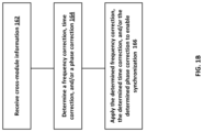
- FIG. 1 B depicts an example of a process for synchronizing radar modules to enable formation of a larger antenna array, in accordance with some embodiments.
- the STPU 190 may receive cross module information.
- the STPU 190 may receive profile information associated with a given target, such as target 150 . This received profile information may include cross module information for a given target.
- the cross module information may include returns received by radar module 102 B due to transmissions from radar module 102 A.
- the cross module information represents receiving returns associated with another radar module's transmissions.
- the cross module information may include the range, Doppler, angle of arrival data, and/or additional information associated with a given target, such as the target 150 .
- the cross module information may include a digital representation (e.g after analog to digital conversion) of the return signals (caused by the transmission by radar module 102 A) and/or other information determined (e.g., measured, calculated, etc.) from the returns. Examples of this other information include target profile information such as the range, Doppler, phase, delay, angle of arrival data obtained from the returns resulting from radar module 102 A's transmission and received by radar module 102 B.
- the STPU 190 may determine, based at least on the cross module information, a frequency correction, a time correction, and/or a phase correction. For example, the STPU may determine a frequency difference based on the cross module information associated with a given target, such as target 150 . This frequency difference may be used as a frequency correction to enable synchronization. Alternatively or additionally, the STPU may determine a time difference based on the cross module information associated with a given target, such as target 150 . The time difference maybe in terms of a clock drift in the envelope of a waveform or the start time of the waveform. This time difference may be used as a time correction to enable synchronization.
- the STPU may determine a phase difference based on the cross module information associated with a given target, such as target 150 .
- the phase difference may be in terms of a relative phase of a local oscillator or a relative clock drift. This phase difference may be used as a phase correction to enable synchronization.
- the determined correction(s) may be applied.
- the STPU 190 may provide feedback to at least one of the radar modules 102 A-B.
- the feedback may be provided via link 122 to for example radar module 102 A or radar module 102 B.
- the feedback may indicate the determined frequency correction, such as a frequency difference determined at 164 , time correction, such as a time difference determined at 164 , and/or the determined phase correction such as the phase difference determined at 164 .
- the radar module 102 A can adjust its reference signal 116 D (or other component in the clock circuitry 108 A) in frequency, time, and/or phase to synchronize with the other radar module's 102 B's reference signal 117 D.
- the determined correction(s) may be applied to the received signal or the corresponding data.
- the STPU 190 may correct the each of the returns (or, e.g., the corresponding digital data for the return) received at radar module 102 B by adjusting the returns (or, e.g., the corresponding digital data for the return) by adding (or subtracting) the determined frequency correction, time correction, and/or phase correction.
- the STPU may process the data for the returns by adjusting phase, frequency, and/or time until there is synchronization in the data associated with a pre-determined calibration target.
- the STPU may only determine the frequency correction, time correction, and/or phase correction, and record these corrections corresponding to the received returns for possible later stage processing.
- the process of FIG. 1 B may be performed in a dynamic manner in the sense that the frequency, time, and/or phase errors may be determined and applied repeatedly to correct the errors as they occur over time.
- FIG. 1 C depicts another example of a process for synchronizing radar modules to enable formation of a larger antenna array, in accordance with some embodiments.
- the STPU 190 may receive cross module information.
- the cross module information may be in the same form as noted above with respect to 162 .
- the radar module 102 B may receive returns caused by transmissions from radar module 102 A. These received returns may be processed to baseband, analog-to-digital converted, and further processed and measured to determine profile information including the cross module information, such as the range, Doppler, angle of arrival data, time delay between pulses returned from the target 150 , and/or additional information.
- the STPU 190 may receive additional information.
- This additional information may include scene information and/or measurements made locally (referred to as in-module measurement measurements).
- the radar module 102 B may receive its own returns. From its own returns, the radar module 102 B may process to baseband, analog-to-digital convert, and determine for a given target the in-module measurement information, such as the range, Doppler, angle of arrival data, time delay between pulses returned from the target 150 , and/or additional information.
- the in-module measurement information may include a digital representation of the return signals caused by radar module 102 B's own transmissions and/or other information determined (e.g., measured, calculated, etc.) from the returns.
- this other information include target profile information such as the range, Doppler, phase, delay, angle of arrival data obtained from the returns resulting from radar module 102 B's transmission and received by radar module 102 B.
- the scene information may include map data or other information about the scene, such as the geo-location (e.g., latitude, longitude, and altitude) of a target such as target 150 , the velocity of the target, etc.
- the scene information may thus indicate, based on the location of the radar modules, possible targets that may be used for synchronizing the radar modules. Based on the geo-location of radar modules 102 A-B at any given instant in time, the STPU may obtain from a database the geolocation of one or more possible targets, such as target 150 . Moreover, the possible targets may be ranked or scored based on the size of target, radar cross section of the object, whether the target was previously used for calibration, and/or the like.
- the scene information may also include velocity (e.g., whether the target is static, whether it is moving, speed and/or direction of target movement, acceleration rate of the target, and/or the like) for the radar modules 102 A-B and/or the possible calibration targets in a scene.
- the STPU 190 may, at 174 , select at least one target as a calibration target, which can be used to determine (e.g., measure, calculate, etc.) a frequency difference, timing difference, and/or a phase difference.
- the STPU 190 may receive returns of a scene collected from one or more radar modules and select from the return data a target, such as target 150 .
- the selection of a target may be based on the information received at 172 , such as the scene information (e.g., map data).
- the target may be selected based on a variety of factors, such as whether the target is stationary, the size (or radar cross section) of the target, whether the target had previously been used successfully as a calibration target, whether the target can be seen by the radar modules, and/or the like.
- the STPU 190 may extract one or more features for the selected target. From the returns (or the digital data representative of the returns) from each of the targets, the extracted features may include target profile information such as range to the target, Doppler associated with the target, angle of arrival with respect to the radar returns, velocity of the target, direction of motion of the target, type of target (e.g., based on the microDoppler seen at the different radar modules), extent (e.g., the number of range-Doppler bins occupied by the target), height of the object, reflection properties (e.g., scattering or specular reflection of the object), and/or the like.
- target profile information such as range to the target, Doppler associated with the target, angle of arrival with respect to the radar returns, velocity of the target, direction of motion of the target, type of target (e.g., based on the microDoppler seen at the different radar modules), extent (e.g., the number of range-Doppler bins occupied by the target), height of the object, reflection properties (e
- the features are extracted from cross module information, such as from the cross module returns caused by transmission from radar module 102 A but received at radar module 102 B.
- the features may be extracted from so-called in-module measurements, such as the returns caused by transmission from radar module 102 A and received at radar module 102 A.
- the STPU 190 may determine, based on the selected target and the corresponding extracted features, a frequency correction, time correction, and/or a phase correction. For a given selected target such as target 150 , the STPU 190 may determine from the extracted features for the selected target 150 , a frequency difference, a time difference, and/or phase difference. To illustrate further, the cross module information corresponding to the selected target 150 enables the STPU to determine frequency, time, and/or phase differences between the reference signals at radar module 102 A and radar module 102 B. The frequency difference may be used as a frequency correction to enable a correction of the frequency of the reference signal 116 D or 117 D.
- the time difference may be used as a time correction (e.g., a true time correction by shifting in time) to enable a correction of the time delay of the reference signal 116 D or 117 D.
- the phase difference may be used as a phase correction to enable a correction of the phase of the reference signal 116 D or 117 D.
- the correction(s) determined at 178 may be applied.
- the application of the correction(s) may be performed in the same or similar manner as noted above at 166 .
- the radar modules may be used cooperatively in a coherent manner by dynamically updating for frequency, time, and/or phase over time to correct for the errors as they occur.
- radar modules 102 A-B may be in different locations and scan a scene from different perspectives to collect returns on a variety of additional target objects.
- the antenna arrays 104 A-N and 106 A-N may comprise an aggregate antenna array of elements 104 A-N and 106 A-N.
- the STPU may determine the errors in frequency, time, and phase and not provide feedback to the radar modules, but instead use the determined errors for post processing correction of the returns.
- FIG. 1 A depicts only two radar modules, the system may include other quantities of radar modules. Moreover, although the example of FIG. 1 A depicts only a single calibration target 150 , a plurality of calibration targets may be used. Likewise, a scene may include a plurality of targets some of which may be stationary and some of which may be in a mobile state. Although FIG. 1 A depicts a one dimensional array of antennas, other quantity of antennas may be implemented including a single antenna and/or other configurations (e.g., two dimensional antenna arrays). At least one of the antennas may be directional, omni-directional, and/or have other patterns. And, at least one of the antennas may comprise a high-gain directive antennas, while at least one of the antennas may comprise a dielectric lens type antenna.
- the STPU provides a virtual synchronizer by providing a feedback to radar modules 102 A-B to correct certain errors (e.g., frequency, time, and/or phase) or by providing a post-processing adjustment to the returns and, in particular, the data corresponding to the returns to correct the returns for certain errors in frequency, time, and/or phase.
- the correction of these errors may be dynamic in the sense that the correction may be performed repeatedly as frequency, time, and/or phase errors change over time. For example, each frame representing a period of time (e.g., a can of a scene) may be processed to correct for phase errors, as well as frequency and/or time.
- the transmitted wave hits the target 150 , which in this example is a calibration target selected to enable calibrating the radar modules 102 A-B for frequency synchronization.
- the radar modules 102 A-B and the target 150 are stationary (e.g., not in a mobile state), although the STPU 190 may correct for frequency and phase even when the target 150 , radar module 102 A, and/or radar module 102 B are in a mobile state as well.
- the receiver at radar module 102 B may have its own reference signal, such as frequency reference ⁇ 2 but the frequency reference ⁇ 2 may not yet be synchronized with the reference signal at radar module 102 A.
- the received return at radar module 102 B may be processed, for example, by down converting, mixing with a local sinusoidal reference signal (e.g., reference signal 117 D), and low-pass filtering.
- a local sinusoidal reference signal e.g., reference signal 117 D
- the STPU 190 may estimate this frequency difference, as noted at 164 and 178 .
- the STPU 190 may compensate for the frequency difference by applying a correction to the received signal (or corresponding data) associated with radar module 102 B (which may be part of a digital post processing of the return signal data at the STPU) as noted at 166 and 180 .
- the STPU 190 may provide a feedback signal to at least one of the radar modules to apply an adjustment to the frequency of the local oscillator to correct for the frequency mismatch, in accordance with some embodiments as noted at 166 and 180 .
- the radar module 102 A may transmit a train (or sequence) of waveforms (e.g., short time-domain pulses, chirp waveforms with a frequency ramp, and/or the like) that illuminate the scene, which in this example includes target 150 .
- the signals reflect off the static targets including calibration target 150 in the scene, and these signals are received by radar module 102 B.
- the two radar modules 102 A-B have the same or similar time reference (e.g., through an external triggering signal).
- the radar modules 102 A-B may rely solely on their free running internal clocks for measuring the time and providing synchronization. This may lead to a clock drift of the relative time references between the two radar modules over time.
- the first pulse as shown at FIG. 2 B may provide an accurate estimate of the range. Supposing the range of the same target 150 is estimated using the second pulse is at 11 meters.
- timing drift in the estimated range from pulse 1 to pulse 2 is due to the timing drift of the clocks (or local oscillators) of the two radar modules 102 A-B.
- This timing (or clock) drift may be given by the following:
- the STPU 190 estimates this timing drift and compensates for the drift in the received radar returns by applying a time correction to the received return data (e.g., as noted above the time correction may be applied as part of a digital post processing of the return signal data at the STPU) or providing a feedback signal to the radar modules 102 A-B to enable a local correction of reference signals 116 D and/or 117 D and/or other components (clocks or local oscillators) for the timing or clock drift.
- a time correction e.g., as noted above the time correction may be applied as part of a digital post processing of the return signal data at the STPU
- the radar modules 102 A-B may enable a local correction of reference signals 116 D and/or 117 D and/or other components (clocks or local oscillators) for the timing or clock drift.
- FIG. 3 depicts the system of FIG. 1 A but in the example of FIG. 3 , the radar modules 102 A-B are moving with respect to the scene including target 150 .
- the radar modules 102 A and 102 B are in a mobile state (e.g., on a moving platform) that moves away from the static calibration target 150 at a given velocity (e.g., which is known or estimated).
- a given velocity e.g., which is known or estimated.
- the radar modules 102 A-B are moving away from the target 150 at a velocity of 1 meter/sec.
- the distance estimated by the second pulse is estimated at 12 meters.
- the STPU 190 receives an accurate estimate of the platform velocity (e.g. using wheel odometer data).
- the mismatch ⁇ R between the estimated range using the second pulse (12 meters in this example) and the expected range based on the knowledge of the platform velocity (11 meters in this example) is due to the clock drift between the two radar modules 102 A-B.
- the STPU may compensate for this clock drift.
- the clock drift may be given by the following:
- timing reference, oscillator frequency, and phase drifts may be estimated using chirp waveforms.
- FIG. 5 depicts an example of a system in which chirp waveforms are used to estimate the clock frequency and phase drifts.
- Radar modules 102 A-B may transmit and receive chirp waveforms.
- a chirp wave form refers to a signal which sweep up in frequency (up-chirp) or sweeps down in frequency (down-chirp).
- a transmitter element at radar module 102 A transmits a train of chirps, and a receiver element at radar modules 102 B receives the returns, such as back-scattered signals resulting from the transmitted train of chirps.
- FIG. 5 shows Fast Fourier Transform (FFT) processor 580 (e.g. a two-dimensional FFT processor), which may process returns (caused by the train of chirps) to form the delay-Doppler plot 599 corresponding to the scene including targets, such as targets 550 A-B.
- FFT Fast Fourier Transform
- the targets 550 A-B are stationary in this example, so the targets should not generate any Doppler shifts in the received signal.
- the radar modules 102 A-B are not synchronized in the phase of their carrier signals (e.g., as the modules 102 A and 102 B may use separate and independent local oscillators), the radar modules may experience somewhat random phase shifts relative to each other.
- the plot 599 shows the output of the two-dimensional FFT processing 580 for estimating the delays and Dopplers.
- the input to the 2D FFT is the received returns from the train of chirps which includes delays and Dopplers induced by the targets in the scene, and the output of the 2D FFT may provide an explicit delay-Doppler domain representation of the received returns.
- the magnitude of the 2D FFT may be plotted as a delay-Doppler profile as shown at FIG. 5 at 599 .
- the phase may be obtained from the output as well (e.g., as the output includes a complex imaginary portion from which the phase can be determined).
- the first dimension of the FFT is taken within each chirp, and the output of the FFT provides delay profile information associated with that chirp, for example the delay profile shown in FIG. 7 B at 750 A.
- the second dimension of the FFT is taken for each FFT bin of the delay profiles and across multiple chirps, providing thus Doppler values corresponding to that delay bin.
- the drifts in time and frequency may be relatively slow, when compared to the more dynamic (e.g., fast changing, such as greater than 10 degrees per 100 micro-seconds) phase drifts.
- the time and frequency may thus be modeled and tracked for correction and compensation of the clocks at the radar modules.
- phase drifts of local oscillators at the radar module may occur at a much faster rate or time-scale relative to clock and frequency drifts and chirp rate, so the dynamics of the phase drift of oscillators may not be as readily modeled and thus not as readily corrected and compensated.
- the phase drifts may not be accurately modeled and tracked by standard filtering techniques, such as Kalman filtering, particle filtering, etc.
- FIG. 6 depicts the system of FIG. 1 but further the plots 699 A and 699 B.
- the plot 699 A depicts the estimated local clock drift in time (e.g., nanoseconds) over time in milliseconds for a frame of chirps.
- the plot 699 B depicts phase drift of the local oscillators (e.g., in degrees) over time (in milliseconds) for a frame of chirps.
- the time drift as shown at plot 699 A may vary slowly, when compared to the more dynamic, fast changes associated with phase drift at 699 B.
- plot 699 A depicts local clock drift, similar “slow varying” results may be obtained for frequency drift of a local oscillator or clock.
- the STPU 190 determines and corrects for slow-varying errors (e.g., clock drift in time and/or frequency), and the STPU determines fast-varying errors associated with phase and corrects for fast-varying errors (e.g., relative phase drift of the local oscillators).
- slow-varying errors e.g., clock drift in time and/or frequency
- fast-varying errors associated with phase and corrects for fast-varying errors e.g., relative phase drift of the local oscillators.
- FIG. 7 depicts an example implementation of a two stage process to estimate and correct for a so-called “slow-varying” error such as clock drift in time and then estimate a so-called “fast-varying” such as phase error and correct for that phase drift.
- a so-called “slow-varying” error such as clock drift in time
- a so-called “fast-varying” such as phase error and correct for that phase drift.
- cross module information may be received by the STPU 190 . This may be implemented in the same or similar manner as noted above with respect to 170 .
- additional information may be received by the STPU. This may be implemented in the same or similar manner as noted above with respect to 172 .
- the STPU 190 may determine delay information, such as a delay profile, corresponding to each received chirp.
- the STPU may receive one or more received chirps transmitted at radar module 102 A but received at radar module 102 B. As the received chirp(s) traverse the scene on their way to the receiver, the signals are affected by the targets (which for example can be measured as a delay).
- the STPU 190 may compute a 1D FFT of the received chirp, which transforms the frequency domain chirp returns into a time domain representation referred to herein as a delay profile.
- the STPU may determine the time duration (or delay) between the time of transmission from the transmitter (e.g., radar module 102 A) and the time of reception at the receiver (e.g., radar module 102 B). For a plurality of received chirps, each delay profile may provide information regarding the delay (as well as range) to possible targets located in the scene. Although the previous example refers to using a chirp, other types of waveforms including a single pulse may be used to determine delay caused by targets in a scene.
- the drift of the FFT bins in the delay profiles may be due to the relative clock drift occurring locally at the radar modules, such as drift occurring at the clock circuitry 108 A-B.
- FIG. 6 at 699 A shows an example of clock drift.
- the radar module 102 A may experience clock drift as shown at 699 A, which may cause other reference signals (e.g., local oscillator reference signals) at radar module 102 A to also drift.
- the radar module 102 B may experience, for example, a different clock drift as shown at 699 A.
- the clocks at each of the radar modules 102 A-B are not synchronized, so the STPU may compute, based on the determined delay profiles for example, the clock drift between the radar modules.
- the STPU 190 may apply a shift to the delay profiles to compensate for drift, such as the delay determined at 710 .
- a first delay profile for a first chirp and a second delay profile for subsequent second chirp may be correlated to determine the shift in time between the delay profiles. This time shift may be used to shift the delay profiles.
- FIG. 7 B depicts at 750 A a first delay profile corresponding to a first chirp transmitted at radar module 102 A but received at radar module 102 B.
- FIG. 7 B depicts at 750 B a second delay profile corresponding to a second chirp transmitted at radar module 102 A but received at radar module 102 B.
- peaks at 760 A-B represent the same static target, so any difference in delay may be attributed to clock drift.
- a correlation is performed to determine the difference (or time shift) in delay between the delay profiles at 750 A-B.
- the determined delay difference is applied, at 712 , to the second delay profile to yield delay profile 750 D.
- the delay profile shown contains at FIG. 7 B includes contributions from multiple targets in the scene.
- the clock drift between consecutive pulses may be determined from the delay profile, without requiring selecting a particular calibration target.
- the delay profiles corresponding to consecutive chirps may stay static. If a drift occurs between the delay profiles, the drift may be attributed to the clock drift of the two radar modules.
- correlating delay profiles across successive intervals at different candidate time offsets, and picking the time offset that yields the best correlation match provides an estimate of the clock drift between the intervals, which can be applied as a shift at 712 to synchronize in time the clock circuitry of the radar modules.
- FIGS. 7 at 710 and 712 refer to computing a delay profile for the pulses and correcting for the delay caused by clock drift, the process may also determine frequency errors and correct for the error as well.
- the STPU 190 may select a stationary calibration target based on a predetermined criteria, in accordance with some embodiments.
- a scene may include a plurality of candidate targets, some of which may be stationary.
- the STPU may select one of the stationary targets, such as target 150 .
- the selection of a target may be based on one or more factors.
- the STPU may select a stationary target that is large or has a good power reflection, such that the corresponding target returns at each of the radar modules 102 A-B have sufficient quality and/or signal strength for processing.
- a static target may correspond to a target, such as a static target 760 A, depicted in the delay profiles 770 A-B.
- the delay profile at 770 A represents the time domain waveform representations of a first chirp transmitted by radar module 102 A and received as a return as radar module 102 B
- the delay profile at 770 B represents the time domain waveform representations of a second chirp transmitted by radar module 102 A and received as a return as radar module 102 B.
- a large static target may affect the chirps and cause the peak 760 A.
- each chirp and corresponding delay profile may have a corresponding phase.
- a phase history representative of the phase changes at a given target may be generated.
- the 1D FFT used to generate the delay profile at 770 A also provides the phase at 760 A for the first chirp
- the 1D FFT used to generate the delay profile at 770 B provides the phase at 760 A for the second chirp.
- This variation in phase from chirp to chirp may provide a phase history representative of the variation in phase occurring at the radar modules 102 A-B (e.g., local oscillator phase drift as depicted at 699 B). This variation may be determined and used to correct at 718 the return data associated with the first and second radar modules.
- the STPU 190 may process the phase history of the selected, stationary target 150 across multiple delay profiles corresponding to multiple, consecutive chirps.
- the phase history corresponding to the selected target (which in this example is 760 A-B which yields the largest amplitude in the range bin in successive delay profiles).
- the phase should not change across multiple delay profiles for the selected, stationary target 150 . If there is a phase change in the estimated phases, the change is due to the relative phase variation of the two oscillators (see, e.g., 699 B showing an example of the relative phase drift of the two oscillators).
- the STPU 190 may, in accordance with some embodiments, correct for the variations of the relative phase of the local oscillators at the radar modules 102 A-B. And, this correction may be based on the estimated phase difference determined at 716 .
- the STPU 190 may correct for the phase drift by providing to each of the radar modules feedback to change the reference signals associated with for example a local oscillator used by the RF circuitry for transmission and/or reception of radar signals.
- the correction may be applied by the STPU as part of so-called post processing.
- the STPU may directly apply a phase correction to the returns (or the digital data representative of the returns) to synchronize in phase the returns (or the digital data representative of the returns) from the first and second radar modules.
- FIG. 8 depicts an example of experimental results where the STPU 190 corrects for clock drift at 712 , by aligning delay profiles as illustrated in FIG. 7 B , and then corrects for phase at 718 by using the phase history of the large stationary target identified in FIG. 7 C .
- the plot 805 depicts delay versus Doppler shift in the case of merely performing 2D FFT processing as shown in FIG. 5 .
- the plot 810 depicts delay versus Doppler shift in the case of after the first stage of timing or frequency correction at 712 .
- the plot 815 depicts delay versus Doppler shift in the case of performing the second stage correction at 718 to correct, for example, relative phase drifts in a local oscillator signal, reference signal, and/or clock source.
- the plot at 815 shows the result of the two stage processing. Specifically, zero Doppler is shown at 815 , which should be the case as the calibration target selected at 714 is static and local clock phase drift is reduced or eliminated at 718 .
- the plots shown in FIG. 8 are based on experimental data.
- the experimental data represents a sequence of chirp waveforms used to capture data from a static scene with the following waveform parameters: the number of chirps transmitted is 64, starting frequency of each chirp is 77 GHz, the slope of each chirp is 30 MHz per micro seconds, the durations of each chirp is 60 micro seconds (the bandwidth of each chirp is about 1.8 GHz, covering between 77 GHz and 78.8 GHz), the sampling rate of the analog to digital converter within each chirp is 10 MHz, the number of samples taken from each chirp is 256.
- the STPU 190 may not explicitly select calibration targets at 714 , but rather the STPU may use the features of the targets in a scene, such as statistical features of the targets in the scene, to determine the errors in the relative phase between the two radar modules 102 A-B. For example, an aggregate statistical parameter, such as the average of the phase history across delay profiles may be used to determine the phase errors in 716 . In this embodiment, 712 and 716 may be combined such that statistical metrics are used to subtract out the clock drift and relative phase errors of the oscillators without performing a formal target selection at 714 . Moreover, additional information may be used such as the rate of change in the scene and/or statistical properties (e.g., average properties) associated with a number of large targets.
- statistical properties e.g., average properties
- FIG. 9 depicts an example of a system including a plurality of radar modules, such as radar modules 102 A-B and radar module 902 including antenna 904 .
- the STPU 190 may receive returns from the radar modules 102 A-B and 902 via wired and/or wireless links to enable the STPU to perform the synchronization disclosed herein.
- the scene being scanned by the radar modules includes a plurality of objects 910 - 916 .
- Object 916 may be in a mobile state.
- one or more of the modules may be in a mobile state.
- radar module 902 may be located on a drone or other type of mobile platform.
- the radar modules may be implemented in the millimeter wave (MMW) band or a portion of the MMW band.
- the radar modules may be implemented to operate in an unlicensed MMW band such as the 57 GHz to 71 GHz band and thus provide high performance radar and imaging systems.
- the frequency of operation of a radar module may span microwave to mm-wave range (3 GHz to 300 GHz).
- the frequency of operation of a radar module may span up to THz frequencies for specific applications (e.g., 300 GHz to 3 THz).
- the radar modules may operate in the range between 20 GHz to 160 GHz.
- the radar modules may operate in the same waveguide band.
- the radio modules 102 A-B and 902 may, when synchronized, provide a scalable millimeter wave array with large aperture including 104 A-N, 106 A-N, and 902 .
- the radar modules may be spatially separated as noted but still maintain frequency, time, and/or phase synchronization, without requiring the distribution of a high frequency synchronization signal to each of the radar modules.
- the radar modules may be spatially separated.
- each radar module may be a distance L from other radar modules.
- the distance L between the two modules may be greater than or equal to 20 times the operating wavelength. If there are 5 or more radar modules in a system, the pairwise distance L may be greater than or equal to 50 times the operating wavelength. And, in some instances, the distance L may be greater than or equal to 100 times the operating wavelengths for larger baselines.
- the radar modules may be located on the same moving platform, different mobile platforms, some on a mobile platform, and/or some on a stationary platform.
- the radar module may, as noted, include transmitter circuitry and/or receiver circuitry coordinated and timed through common baseband signal, control, and timing signals, and may include envelope locking but not necessarily the carrier phase for full coherency.
- Each radar module may also include circuitry for up/down frequency conversion block(s), memory unit(s), buffer(s), analog to digital converter(s), local processing unit(s), RF amplifier(s), RF splitter(s)/combiner(s), phase shifter(s) or mixer(s).
- the circuitry within a given radar module may share a common reference signal, such as the same clock and/or local oscillator.
- a given radar module may transmit and receive coherently. And, the radar module may operate in MIMO configuration.
- a given radar module may use a local reference signal to enable synchronization of transmission and/or receiver circuitry in time, frequency and phase (e.g., fed by the same carrier signal that is locked to a stable reference, for example a crystal).
- a transceiver element can be set to be either in transmit mode or receive mode.
- the antenna elements of a radar module may be uniformly space, although the antenna elements may not necessarily uniformly spaced as well.
- the circuitry within a radar module may be fully synchronized in time, frequency, and phase, so each radar module may coherently process the data captured from its own transmit, receive, and/or transceiver elements.
- the STPU 190 may provide synchronization in frequency, time, and/or phase.
- This synchronization may take the form of the STPU synchronizing the returns (e.g., digital data representative of the returns) in frequency, time, and phase as a post-processing function as noted above.
- this synchronization may take the form of the STPU providing feedback to the radar modules to correct for frequency, time, and/or phase.
- the spatially separated radar modules may create a large aperture which provides resolution enhancement in azimuth and elevation angles (depending on the geometrical arrangement of the modules). Further, the spatially, separated radar modules may provide the capability of looking at the scene from different vantage points, which may improve the detection capability of the radar system for complex and spatially-extended targets. And, the capability of transmission and reception from different and spatially separated radar modules (and the corresponding cross-module measurements) may significantly improve the overall system sensitivity and performance by improving the signal-to-noise ratio (SNR) of the target responses and improving the Radar Cross Section (RCS) of spatially extended targets (transmission at a certain angle and reception from a different angle).
- SNR signal-to-noise ratio
- RCS Radar Cross Section
- the radar modules may collect specular and/or diffuse reflections from targets at different ranges.
- the radar modules may be locked (e.g., synchronized) in frequency or time delay, but not phase.
- the process at FIG. 7 A may still be used.
- at least 716 and 718 may be performed to correct for the phase drift.
- the radar modules may share a common clock, such as a GPS clock reference or a common clock distributed across modules.
- a common clock such as a GPS clock reference or a common clock distributed across modules.
- the process at FIG. 7 A may still be used. For example, at least 716 and 718 may be performed to correct for the phase drift.
- the local oscillator may be locked through for example phase locked loop circuitry to a low frequency reference, such as a crystal oscillator based reference, such as 116 A. Even if the low frequency reference is shared among radar modules, one or more aspect of the process at FIG. 7 A may still be used to correct for phase and/or further adapt the errors among the radar modules in frequency or time.
- FIG. 10 depicts an example of a radar module.
- the radar module may include a receive portion and a transmit portion.
- the receive portion may include one or more antennas 1010 coupled to at least one low noise amplifier (LNA) 1012 .
- the output of the LNA 1012 may be coupled to an input of mixer 1014 .
- Mixer 1014 includes a reference signal 1018 , which may be used to enable the downconversion provided by mixer 1014 .
- the output of the mixer 1014 may be coupled to a filter 1016 , such as a bandpass or lowpass filter.
- the output of the filter may then undergo analog-to-digital conversion 1020 .
- the output the analog-to-digital converter 1020 may include digital data representative of the radar returns received via the antenna(s) 1010 . This digital data may be further processed digitally including processing by the STPU 190 .
- the transmit portion may receive a radar waveform 1008 , which is upconverted using the local oscillator (LO) 1006 , and then amplified via power amplifier 1004 for transmission via one or more antennas 1002 .
- the power amplifier 1004 can be turned off, so that the radar module can operate as a receiver-only module.
- the received signal is received by antenna 1010 and amplified via the low noise amplifier 1012 .
- the bandpass signal 1018 from the transmitter is mixed against the received signal at the output of the LNA 1012 , using mixer 1014 .
- the radar module may include additional circuitry as well including clock circuitry, etc.
- the radar modules transmit and/or receive frequency modulated waveforms with a center frequency in the 20 GHz to 160 GHz range.
- the waveforms may comprise frequency chirps in form of frequency modulated, continuous wave (FMCW) or stepped-frequency continuous wave signals.
- FMCW frequency modulated, continuous wave
- the transmission and/or reception of these waveforms may be in one frequency band or multiple frequency bands across the microwave or millimeter wave frequency ranges.
- the radar modules may be in partial synchronization (e.g., in time, frequency, and/or phase) using phased-locked loops and/or local frequency multipliers by distributing a local oscillator at frequency which may be a fraction of the carrier frequency (e.g., 0.25 times the carrier frequency or less).
- the processes disclosed herein may be used to further enhance the synchronization by reducing time, frequency, and/or phase errors between the radar modules.
- the STPU 190 may, as noted, provide a feedback signal to adjust the frequency, time, and/or phase.
- the STPU may adjust the frequency, time, and/or phase of the local oscillator 1006 , which provides a reference signal for the downconversion provided by the mixer 1014 . This adjustment may thus correct for phase drift of the local oscillator signal 1018 as well as other errors associated with frequency or time.
- the adjustment may also adjust the frequency, time, and/or phase of other components, such as the frequency reference 116 A, 117 A, and/or the like.
- FIG. 10 depicts an example of a radar module
- the radar module may take other forms.
- the transmit portion and receive portion may be implemented in a duplex configuration, in which case the radar module may switch between transmit and receive configurations while sharing the same antennas.
- the system and methods disclosed herein may correct errors generated by other sources.
- the phase variation in the received return signals may be due to mechanical vibrations of the radar module rather than phase variations of the oscillators, and this phase variation may be determined and corrected as disclosed herein.
- another source of error or drift in phase, frequency, and timing of the signals may be caused by temperature variations, and this phase, frequency, and timing variation may be determined and corrected as disclosed herein.
- the STPU may, based on the cross module information, determine a mismatch between the waveform generated at the transmitter in radar module 102 A and the waveform generated at the receiver in radar module 102 B. Given the radar modules are using a chirp waveform for example, the STPU may determine a mismatch between the slopes of the chirps generated at the transmitter and the receiver.
- a technical effect of one or more of the example embodiments disclosed herein may be enhanced frequency, time, and/or phase synchronization.
- the system 100 including the frequency, time, and/or phase correction disclosed herein may be used to provide an antenna array comprising spatially separate radar modules (each of which has one or more antenna elements).
- the system 100 may be used in mobile or stationary applications.
- the system 100 may be used in air-to-air, air-to-ground, or ground-to-ground application.
- the system 100 may be used to provide gesture detection (e.g., in mobile, large screens, and/or interactive systems), feedback in augmented reality/virtual reality) applications or entertainment systems.
- the base stations and user equipment (or one or more components therein) and/or the processes described herein can be implemented using one or more of the following: a processor executing program code, an application-specific integrated circuit (ASIC), a digital signal processor (DSP), an embedded processor, a field programmable gate array (FPGA), and/or combinations thereof.
- ASIC application-specific integrated circuit
- DSP digital signal processor
- FPGA field programmable gate array
- These various implementations may include implementation in one or more computer programs that are executable and/or interpretable on a programmable system including at least one programmable processor, which may be special or general purpose, coupled to receive data and instructions from, and to transmit data and instructions to, a storage system, at least one input device, and at least one output device.
- These computer programs also known as programs, software, software applications, applications, components, program code, or code
- computer-readable medium refers to any computer program product, machine-readable medium, computer-readable storage medium, apparatus and/or device (for example, magnetic discs, optical disks, memory, Programmable Logic Devices (PLDs)) used to provide machine instructions and/or data to a programmable processor, including a machine-readable medium that receives machine instructions.
- PLDs Programmable Logic Devices
- systems are also described herein that may include a processor and a memory coupled to the processor.
- the memory may include one or more programs that cause the processor to perform one or more of the operations described herein.
Landscapes
- Engineering & Computer Science (AREA)
- Radar, Positioning & Navigation (AREA)
- Remote Sensing (AREA)
- Computer Networks & Wireless Communication (AREA)
- Physics & Mathematics (AREA)
- General Physics & Mathematics (AREA)
- Radar Systems Or Details Thereof (AREA)
Abstract
Description
x 1(t-τ)=A′cos(ω1(t-τ)+φ1+φr) (1).
x 1(t-τ) *x 2(t)=A′cos(ω1(t-τ)+φ1+φr) * A 2cos(ω2 t+φ 2)=1/2A′A 2[cos((ω1+ω2)t-ω1τ+φ1+φr+φ2)+cos ((ω1-ω2)t-ω1τ+φ1+φr-φ2)] (2).
LPF{x 1(t-τ)* x 2(t)}=1/2A′A 2cos (Δωt+ω3) (3),
where Δω=ω1-ω2 and φ3=−ω1τ+φ1+φr−φ2. Since the
Claims (19)
Priority Applications (1)
| Application Number | Priority Date | Filing Date | Title |
|---|---|---|---|
| US16/955,757 US11656325B2 (en) | 2017-12-19 | 2018-12-19 | Methods and apparatus to realize scalable antenna arrays with large aperture |
Applications Claiming Priority (3)
| Application Number | Priority Date | Filing Date | Title |
|---|---|---|---|
| US201762607660P | 2017-12-19 | 2017-12-19 | |
| US16/955,757 US11656325B2 (en) | 2017-12-19 | 2018-12-19 | Methods and apparatus to realize scalable antenna arrays with large aperture |
| PCT/US2018/066598 WO2019126386A1 (en) | 2017-12-19 | 2018-12-19 | Methods and apparatus to realize scalable antenna arrays with large aperture |
Publications (2)
| Publication Number | Publication Date |
|---|---|
| US20210011121A1 US20210011121A1 (en) | 2021-01-14 |
| US11656325B2 true US11656325B2 (en) | 2023-05-23 |
Family
ID=66993867
Family Applications (1)
| Application Number | Title | Priority Date | Filing Date |
|---|---|---|---|
| US16/955,757 Active 2039-07-29 US11656325B2 (en) | 2017-12-19 | 2018-12-19 | Methods and apparatus to realize scalable antenna arrays with large aperture |
Country Status (3)
| Country | Link |
|---|---|
| US (1) | US11656325B2 (en) |
| EP (1) | EP3729130A4 (en) |
| WO (1) | WO2019126386A1 (en) |
Families Citing this family (16)
| Publication number | Priority date | Publication date | Assignee | Title |
|---|---|---|---|---|
| KR102388027B1 (en) * | 2018-12-26 | 2022-04-19 | 삼성전자 주식회사 | A method for testing a wireless communication module, and an electronic device including the wireless communication module |
| US11971503B2 (en) | 2019-02-19 | 2024-04-30 | Koko Home, Inc. | System and method for determining user activities using multiple sources |
| US10810850B2 (en) | 2019-02-19 | 2020-10-20 | Koko Home, Inc. | System and method for state identity of a user and initiating feedback using multiple sources |
| KR102182293B1 (en) * | 2019-03-11 | 2020-11-24 | 현대모비스 주식회사 | Apparatus and mehtod for estimating direction of arrival in mimo system |
| US11520030B2 (en) * | 2019-03-18 | 2022-12-06 | Nxp Usa, Inc. | High resolution automotive radar system with forward and backward difference co-array processing |
| US11092683B2 (en) | 2019-03-18 | 2021-08-17 | Nxp Usa, Inc. | Distributed aperture automotive radar system with alternating master radar devices |
| US11269049B2 (en) | 2019-03-18 | 2022-03-08 | Nxp Usa, Inc. | Distributed aperture automotive radar system |
| US11240635B1 (en) * | 2020-04-03 | 2022-02-01 | Koko Home, Inc. | System and method for processing using multi-core processors, signals, and AI processors from multiple sources to create a spatial map of selected region |
| EP3913391A1 (en) * | 2020-05-20 | 2021-11-24 | Infineon Technologies AG | Processing radar signals |
| US11550029B2 (en) * | 2020-07-16 | 2023-01-10 | Analog Devices International Unlimited Company | Delay calibration for a stepped frequency continuous wave digital signal chain |
| US11888554B2 (en) | 2020-09-23 | 2024-01-30 | Nxp Usa, Inc. | Automotive MIMO radar system using efficient difference co-array processor |
| US11762079B2 (en) | 2020-09-30 | 2023-09-19 | Aurora Operations, Inc. | Distributed radar antenna array aperture |
| US11899127B2 (en) | 2020-09-30 | 2024-02-13 | Aurora Operations, Inc. | Virtual antenna array with distributed aperture |
| CN114943242A (en) * | 2021-02-08 | 2022-08-26 | 北京小米移动软件有限公司 | Event detection method and device, electronic equipment and storage medium |
| CN113721228B (en) * | 2021-09-07 | 2024-05-03 | 北京航空航天大学 | Parameter correction and data processing method for area array single photon detection system |
| DE102021210121A1 (en) * | 2021-09-14 | 2023-03-16 | Robert Bosch Gesellschaft mit beschränkter Haftung | Radar system and method using a virtual sensor |
Citations (4)
| Publication number | Priority date | Publication date | Assignee | Title |
|---|---|---|---|---|
| WO2005010556A1 (en) | 2003-07-18 | 2005-02-03 | University Of Nottingham | Radar position and movement measurement for geophysical monitoring |
| US20060220951A1 (en) | 2005-04-04 | 2006-10-05 | Raytheon Company | System and method for coherently combining a plurality of radars |
| US20150276917A1 (en) * | 2012-11-02 | 2015-10-01 | Qinetiq Limited | Radar imaging system |
| US9182485B1 (en) | 2011-05-24 | 2015-11-10 | Garmin International, Inc. | Transmit/receive module for electronically steered weather radar |
-
2018
- 2018-12-19 US US16/955,757 patent/US11656325B2/en active Active
- 2018-12-19 EP EP18890553.3A patent/EP3729130A4/en active Pending
- 2018-12-19 WO PCT/US2018/066598 patent/WO2019126386A1/en unknown
Patent Citations (4)
| Publication number | Priority date | Publication date | Assignee | Title |
|---|---|---|---|---|
| WO2005010556A1 (en) | 2003-07-18 | 2005-02-03 | University Of Nottingham | Radar position and movement measurement for geophysical monitoring |
| US20060220951A1 (en) | 2005-04-04 | 2006-10-05 | Raytheon Company | System and method for coherently combining a plurality of radars |
| US9182485B1 (en) | 2011-05-24 | 2015-11-10 | Garmin International, Inc. | Transmit/receive module for electronically steered weather radar |
| US20150276917A1 (en) * | 2012-11-02 | 2015-10-01 | Qinetiq Limited | Radar imaging system |
Non-Patent Citations (1)
| Title |
|---|
| Kong, S. et al. (Jan. 1, 2014). "Wireless Cooperative Synchronization of Coherent UWB MIMO Radar," IEEE Transactions on Microwave Theory and Techniques 62(1):154-165. |
Also Published As
| Publication number | Publication date |
|---|---|
| EP3729130A1 (en) | 2020-10-28 |
| US20210011121A1 (en) | 2021-01-14 |
| EP3729130A4 (en) | 2021-09-15 |
| WO2019126386A1 (en) | 2019-06-27 |
Similar Documents
| Publication | Publication Date | Title |
|---|---|---|
| US11656325B2 (en) | Methods and apparatus to realize scalable antenna arrays with large aperture | |
| US11906655B2 (en) | Method and apparatus for capturing the surroundings | |
| Gottinger et al. | Coherent automotive radar networks: The next generation of radar-based imaging and mapping | |
| JP4665590B2 (en) | Interferometric radar | |
| JP4496954B2 (en) | Interferometric radar | |
| US20180088221A1 (en) | Multi-radar system | |
| JP5197138B2 (en) | Multi static radar device | |
| US20180241477A1 (en) | Phase-error correction in a synthetic aperture imaging system with local oscillator time delay adjustment | |
| CN114706063A (en) | Method in a radar system, radar system or arrangement of radar systems | |
| JP2014517253A (en) | FMCW radar system with multiple transmitters and beat frequency multiplex | |
| US20220003835A1 (en) | Radar apparatus and method for determining range side lobe | |
| US20220334217A1 (en) | Radar method and radar system | |
| US20210080540A1 (en) | Method and device for compensating for interfering influences | |
| RU2496120C2 (en) | Multifunctional multirange scalable radar system for aircraft | |
| Frischen et al. | FMCW ramp non-linearity effects and measurement technique for cooperative radar | |
| US7961139B2 (en) | Digital beam forming using frequency-modulated signals | |
| Wang | Approach of adaptive synchronization for bistatic SAR real-time imaging | |
| Ma et al. | High-resolution microwave photonic radar with sparse stepped frequency chirp signals | |
| Edstaller et al. | A cooperative radar system with active reference target synchronization for kinematic target analysis | |
| KR101568239B1 (en) | Apparatus and method for processing signal for millimeter wave seeker | |
| Anghel et al. | Simplified bistatic SAR imaging with a fixed receiver and TerraSAR-X as transmitter of opportunity-First results | |
| JP6573748B2 (en) | Radar equipment | |
| Pan et al. | Impacts of space-time-frequency synchronization errors onwideband target echo characteristics of bistatic/multistatic radar | |
| EP4258019A1 (en) | Phase noise reduction for symmetric bistatic radar | |
| Wang | Bistatic synthetic aperture radar synchronization processing |
Legal Events
| Date | Code | Title | Description |
|---|---|---|---|
| AS | Assignment |
Owner name: THE BOARD OF TRUSTEES FOR THE LELAND STANFORD JUNIOR UNIVERSITY, CALIFORNIA Free format text: ASSIGNMENT OF ASSIGNORS INTEREST;ASSIGNORS:ARBABIAN, MOHAMMAD AMIN;MAMANDIPOOR, BABAK;REEL/FRAME:052983/0759 Effective date: 20190109 |
|
| FEPP | Fee payment procedure |
Free format text: ENTITY STATUS SET TO UNDISCOUNTED (ORIGINAL EVENT CODE: BIG.); ENTITY STATUS OF PATENT OWNER: SMALL ENTITY |
|
| FEPP | Fee payment procedure |
Free format text: ENTITY STATUS SET TO SMALL (ORIGINAL EVENT CODE: SMAL); ENTITY STATUS OF PATENT OWNER: SMALL ENTITY |
|
| STPP | Information on status: patent application and granting procedure in general |
Free format text: APPLICATION DISPATCHED FROM PREEXAM, NOT YET DOCKETED |
|
| STPP | Information on status: patent application and granting procedure in general |
Free format text: DOCKETED NEW CASE - READY FOR EXAMINATION |
|
| STPP | Information on status: patent application and granting procedure in general |
Free format text: NON FINAL ACTION MAILED |
|
| STPP | Information on status: patent application and granting procedure in general |
Free format text: RESPONSE TO NON-FINAL OFFICE ACTION ENTERED AND FORWARDED TO EXAMINER |
|
| STCF | Information on status: patent grant |
Free format text: PATENTED CASE |