US11313944B2 - Horizontal and vertical polarization beamforming in a radar system - Google Patents
Horizontal and vertical polarization beamforming in a radar system Download PDFInfo
- Publication number
- US11313944B2 US11313944B2 US16/415,253 US201916415253A US11313944B2 US 11313944 B2 US11313944 B2 US 11313944B2 US 201916415253 A US201916415253 A US 201916415253A US 11313944 B2 US11313944 B2 US 11313944B2
- Authority
- US
- United States
- Prior art keywords
- reflected signals
- horizontal
- radar system
- polarization
- signal
- Prior art date
- Legal status (The legal status is an assumption and is not a legal conclusion. Google has not performed a legal analysis and makes no representation as to the accuracy of the status listed.)
- Active, expires
Links
Images


Classifications
-
- G—PHYSICS
- G01—MEASURING; TESTING
- G01S—RADIO DIRECTION-FINDING; RADIO NAVIGATION; DETERMINING DISTANCE OR VELOCITY BY USE OF RADIO WAVES; LOCATING OR PRESENCE-DETECTING BY USE OF THE REFLECTION OR RERADIATION OF RADIO WAVES; ANALOGOUS ARRANGEMENTS USING OTHER WAVES
- G01S7/00—Details of systems according to groups G01S13/00, G01S15/00, G01S17/00
- G01S7/02—Details of systems according to groups G01S13/00, G01S15/00, G01S17/00 of systems according to group G01S13/00
- G01S7/024—Details of systems according to groups G01S13/00, G01S15/00, G01S17/00 of systems according to group G01S13/00 using polarisation effects
- G01S7/025—Details of systems according to groups G01S13/00, G01S15/00, G01S17/00 of systems according to group G01S13/00 using polarisation effects involving the transmission of linearly polarised waves
-
- G—PHYSICS
- G01—MEASURING; TESTING
- G01S—RADIO DIRECTION-FINDING; RADIO NAVIGATION; DETERMINING DISTANCE OR VELOCITY BY USE OF RADIO WAVES; LOCATING OR PRESENCE-DETECTING BY USE OF THE REFLECTION OR RERADIATION OF RADIO WAVES; ANALOGOUS ARRANGEMENTS USING OTHER WAVES
- G01S13/00—Systems using the reflection or reradiation of radio waves, e.g. radar systems; Analogous systems using reflection or reradiation of waves whose nature or wavelength is irrelevant or unspecified
- G01S13/02—Systems using reflection of radio waves, e.g. primary radar systems; Analogous systems
- G01S13/04—Systems determining presence of a target
-
- G—PHYSICS
- G01—MEASURING; TESTING
- G01S—RADIO DIRECTION-FINDING; RADIO NAVIGATION; DETERMINING DISTANCE OR VELOCITY BY USE OF RADIO WAVES; LOCATING OR PRESENCE-DETECTING BY USE OF THE REFLECTION OR RERADIATION OF RADIO WAVES; ANALOGOUS ARRANGEMENTS USING OTHER WAVES
- G01S13/00—Systems using the reflection or reradiation of radio waves, e.g. radar systems; Analogous systems using reflection or reradiation of waves whose nature or wavelength is irrelevant or unspecified
- G01S13/88—Radar or analogous systems specially adapted for specific applications
- G01S13/93—Radar or analogous systems specially adapted for specific applications for anti-collision purposes
- G01S13/931—Radar or analogous systems specially adapted for specific applications for anti-collision purposes of land vehicles
-
- H—ELECTRICITY
- H01—ELECTRIC ELEMENTS
- H01Q—ANTENNAS, i.e. RADIO AERIALS
- H01Q15/00—Devices for reflection, refraction, diffraction or polarisation of waves radiated from an antenna, e.g. quasi-optical devices
- H01Q15/24—Polarising devices; Polarisation filters
Definitions
- the subject disclosure relates to horizontal and vertical polarization beamforming in a radar system.
- Vehicles e.g., automobiles, trucks, construction equipment, farm equipment, automated factory equipment
- sensors include a radio detection and ranging (radar) system, a light detection and ranging (lidar) system, and a camera.
- a radar system for example, involves the transmission of a radio frequency (RF) signal and reception of reflections of that signal by one or more objects in the field of view of the radar system. Processing of the reflections provides a range and angle to each object and may also provide relative range rate (i.e., Doppler).
- RF radio frequency
- a fast Fourier transform (FFT) may be used to determine the range while a beamforming process may be used to determine the angle.
- FFT fast Fourier transform
- radar systems in vehicles use vertical polarization. Accordingly, it is desirable to provide horizontal and vertical polarization beamforming in a radar system.
- a method in one exemplary embodiment, includes transmitting both horizontal and vertical polarizations from a radar system, and receiving, using a first antenna of the radar system, first reflected signals with horizontal polarization. The method also includes receiving, using a second antenna of the radar system, second reflected signals with vertical polarization. The first reflected signals and the second reflected signals are processed together to obtain one or more angles to respective one or more objects detected by the radar system.
- the transmitting both the horizontal and the vertical polarizations includes transmitting a combined signal resulting from feeding a signal both horizontally and vertically to an antenna for transmission.
- the transmitting both the horizontal and the vertical polarizations includes transmitting one signal with horizontal polarization and one signal with vertical polarization.
- the processing the first reflected signals and the second reflected signals includes performing beamforming to obtain a likelihood indicator P( ⁇ ) as:
- the method also includes selecting a value of the regularization factor ⁇ .
- the obtaining the one or more angles includes applying a detection threshold to the likelihood indicator P( ⁇ ).
- the method also includes locating the radar system in a vehicle.
- a radar system transmits both horizontal and vertical polarizations, to receive first reflected signals with horizontal polarization and to receive second reflected signals with vertical polarization.
- a processor processes the first reflected signals and the second reflected signals together to obtain one or more angles to respective one or more objects detected by the radar system.
- the radar system is configured to transmit a combined signal with both the horizontal and the vertical polarizations based on feeding a signal both horizontally and vertically to an antenna for transmission.
- the radar system is configured to transmit one signal with horizontal polarization and one signal with vertical polarization in order to transmit both the horizontal and the vertical polarizations.
- the processor is configured to perform beamforming to obtain a likelihood indicator P( ⁇ ) as:
- the regularization factor ⁇ is a selected value.
- the processor is configured to obtain the one or more angles by applying a detection threshold to the likelihood indicator P( ⁇ ).
- the radar system is in a vehicle.
- FIG. 1 is a block diagram of a vehicle that benefits from object detection using horizontal and vertical polarization beamforming in a radar system according to one or more embodiments;
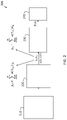
- FIG. 2 is a process flow of a method of using horizontal and vertical polarization beamforming in a radar system according to one or more embodiments.
- FIG. 3 illustrates beamforming results for comparison of horizontal and vertical polarization beamforming according to one or more embodiments with single-polarization beamforming according to conventional approaches.
- a radar system is among the sensors that may be used to obtain information about an environment (e.g., objects in the vicinity) of a vehicle.
- the information obtained by the radar system may be used to control aspects of vehicle operation (e.g., collision avoidance, adaptive cruise control, automated braking) under an autonomous or semi-autonomous control scheme.
- RF signals with vertical polarization are generally used. Polarization of the RF signal transmitted by a radar system is controlled by the way that the RF signal is fed to the transmitting antenna. For example, when the signal is fed to the antenna laterally (from left to right or right to left), horizontal polarization is achieved. When the signal is fed to the antenna from top to bottom or bottom to top, vertical polarization is achieved.
- a transmitted RF signal may have both horizontal and vertical polarization. This is achieved by feeding the RF signal both horizontally and vertically to the antenna.
- the intensity of the RF signal in each direction need not be, but can be, equal.
- Embodiments of the systems and methods detailed herein relate to horizontal and vertical polarization beamforming in a radar system. By transmitting and receiving both horizontal and vertical polarizations, the beamforming according to one or more embodiments results in increased angular resolution when compared to traditional beamforming using a single polarization.
- FIG. 1 is a block diagram of a vehicle 100 that benefits from object detection using horizontal and vertical polarization beamforming in a radar system 110 .
- the exemplary vehicle 100 shown in FIG. 1 is an automobile 101 .
- the radar system 110 may be a multi-input multi-output (MIMO) system with multiple transmit and multiple receive antenna elements.
- the vehicle 100 may include additional sensors 130 (e.g., lidar system, camera).
- a controller 120 may control aspects of the operation of the vehicle 100 using information from the radar system 110 and/or other sensors 130 .
- the radar system 110 emits transmit signals 112 that have both horizontal and vertical polarization, as indicated.
- polarization of the emitted transmit signal 112 is based on the orientation with which the signal is fed to the antenna of the radar system 110 .
- the transmit signal 112 with 45 degree polarization as indicated by the dashed line, may be produced.
- the transmit signal 112 with both horizontal and vertical polarization encounters an object 140 , the result is a reflected signal 115 h with horizontal polarization and a reflected signal 115 v with vertical polarization (generally referred to as reflected signals 115 ) reflected back to the radar system 110 .
- antennas 111 are shown for the radar system 110 .
- the antennas 111 that transmit and receive may be separate (i.e., the radar system 110 may not use a transceiver arrangement) and separate antennas 111 may receive the reflected signal with horizontal polarization 115 h and the reflected signal with vertical polarization 115 v .
- the spacing among antennas 111 that receive reflected signals 115 h with horizontal polarization and the spacing among antennas 111 that receive reflected signals 115 v with vertical polarization is assumed to be the same. Thus, if the two exemplary antennas 111 shown in FIG.
- two antennas 111 that receive reflected signals 115 v with vertical polarization may be directly below or above the antennas 111 that are shown.
- the two antennas 111 that receive reflected signals 115 h with horizontal polarization may be beside the two antennas 111 that receive reflected signals 115 v with vertical polarization, as another example.
- the relevant aspect of the arrangement is that the two antennas that receive reflected signals 115 h with horizontal polarization are separated by the same amount as the two antennas 111 that receive reflected signals 115 v with vertical polarization.
- the two exemplary objects 140 shown in FIG. 1 are pedestrians 145 .
- Angular resolution refers to accurately discerning the angle of arrival of reflected signals 115 from one of the pedestrians 145 from the angle of arrival of reflected signals 115 from the other pedestrian 145 .
- the processing of reflected signals 115 received by the radar system 110 may be performed within the radar system 110 , by the controller 120 , or a combination of the two.
- the processing, whether in the radar system 110 or controller 120 involves processing circuitry that may include an application specific integrated circuit (ASIC), an electronic circuit, a processor (shared, dedicated, or group) and memory that executes one or more software or firmware programs, a combinational logic circuit, and/or other suitable components that provide the described functionality.
- ASIC application specific integrated circuit
- processor shared, dedicated, or group
- memory that executes one or more software or firmware programs, a combinational logic circuit, and/or other suitable components that provide the described functionality.
- FIG. 2 is a process flow of a method 200 of using horizontal and vertical polarization beamforming in a radar system 110 according to one or more embodiments.
- transmitting a transmit signal 112 with horizontal and vertical polarization may include transmitting separate horizontal and vertical polarization signals or transmitting both together as a 45 degree signal. Transmitting horizontal and vertical polarization transmit signals 112 separately may be done using different antennas 111 for each. Alternately, as previously noted, by feeding the signal to the antenna 111 both horizontally and vertically, a transmit signal 112 with both horizontal and vertical polarization may be emitted.
- receiving reflected signals 115 includes receiving both reflected signals 115 h with horizontal polarization and reflected signals 115 v with vertical polarization using different antennas 111 .
- a transmit signal 112 with both horizontal and vertical polarization may be transmitted by one antenna 111 according to an exemplary embodiment, two separate antennas 111 are used to respectively obtain reflected signals 115 h with horizontal polarization and reflected signals 115 v with vertical polarization.
- the reflected signals 115 h with horizontal polarization and reflected signals 115 v with vertical polarization are referred to and represented, respectively, as y v and y h .
- M is the number of reflected signals 115 .
- the array response vector ⁇ ( ⁇ m ) for an angle of arrival ⁇ m is the same for both the reflected signals 115 h with horizontal polarization and reflected signals 115 v with vertical polarization. This is because, as previously noted, the spacing among antennas 111 that receive the reflected signals 115 h with horizontal polarization and the spacing among antennas 111 that receive the reflected signals 115 v with vertical polarization is assumed to be the same. Specifically:
- a ⁇ ( ⁇ ) [ e j ⁇ ⁇ 2 ⁇ ⁇ ⁇ ⁇ x 0 ⁇ si ⁇ ⁇ n ⁇ ( ⁇ ) ⁇ ⁇ ⁇ e j ⁇ ⁇ 2 ⁇ ⁇ ⁇ ⁇ ⁇ x 1 ⁇ ⁇ si ⁇ ⁇ n ⁇ ( ⁇ ) ⁇ ⁇ ⁇ ... ⁇ ⁇ e j ⁇ ⁇ 2 ⁇ ⁇ ⁇ ⁇ x i ⁇ si ⁇ ⁇ n ⁇ ( ⁇ ) ] T [ EQ . ⁇ 3 ]
- x i indicates the position of the antenna 111 within the MIMO array and ⁇ is the wavelength of the transmit signal 112 .
- each polarized antenna 111 is a superposition of the same steering vectors ⁇ ( ⁇ m ) but with different reflection coefficients.
- the approach of transmitting both horizontal and vertical polarizations results in two independent realizations. These independent realizations facilitate increased angular resolution based on applying a beamforming method, according to one or more embodiments, at block 230 .
- performing beamforming refers to determining a likelihood value for each angle ⁇ using both the reflected signals 115 h with horizontal polarization and reflected signals 115 v with vertical polarization or y v and y h .
- P ( ⁇ ) ⁇ w ⁇ H y v +w ⁇ H y h ⁇ w [EQ. 4]
- w ⁇ argmin w ⁇ w ⁇ H y v +w ⁇ H y h ⁇ 2 [EQ. 5]
- R y v ⁇ y v H + y h ⁇ y h H [ EQ . ⁇ 8 ]
- R is the sum of the autocorrelations of the reflected signals 115 h with horizontal polarization and reflected signals 115 v with vertical polarization or y v and y h .
- ⁇ is the regularization factor
- I is an identity matrix.
- the regularization factor ⁇ is selected based on a tradeoff between accuracy and robustness to uncertainty in ⁇ ( ⁇ ) and R. That is, when the regularization factor ⁇ is set at 0, there is no regularization. When the regularization factor ⁇ is set to the maximum eigenvalue of R, the most robust but least accurate likelihood P( ⁇ ) is obtained.
- finding the peaks refers to finding the one or more values of ⁇ for which the likelihood P( ⁇ ) is highest (e.g., over a defined detection threshold value). These one or more values of ⁇ are the respective estimated angles of one or more objects 140 relative to the radar system 110 .
- FIG. 3 illustrates beamforming results 300 for comparison of horizontal and vertical polarization beamforming according to one or more embodiments with single-polarization beamforming according to conventional approaches.
- azimuth ( ⁇ ) in degrees (deg) is indicated along one axis
- signal strength in decibels (dB) is indicated along another, perpendicular axis.
- the beamforming result A is based on conventional beamforming that uses transmissions and reflections with a single polarization.
- the beamforming result B is based on transmit signals 112 that include both horizontal and vertical polarization and reflected signals 115 h with horizontal polarization and reflected signals 115 v with vertical polarization.
- the beamforming result B is P( ⁇ ).
- both beamforming results A and B indicate likelihood for the various azimuth angles.
- An exemplary detection threshold (DT) is shown. Angles for which the beamforming result A or B exceeds the DT may be regarded as relative angles of detected objects 140 .
- two exemplary objects 140 - 1 and 140 - 2 result in two distinct peaks in the beamforming result B, which is obtained using horizontal and vertical polarization.
- the angle to object 140 - 1 is 5 degrees
- the angle to object 140 - 2 is 7 degrees.
- the beamforming result A which is obtained with a single polarization, does not clearly show that two objects 140 are present. In fact, it may appear that the angle to one object 140 was detected over a spread of angles.
Landscapes
- Engineering & Computer Science (AREA)
- Radar, Positioning & Navigation (AREA)
- Remote Sensing (AREA)
- Physics & Mathematics (AREA)
- Computer Networks & Wireless Communication (AREA)
- General Physics & Mathematics (AREA)
- Electromagnetism (AREA)
- Radar Systems Or Details Thereof (AREA)
Abstract
Description
y h=Σm=0 Mα(θm)βm, and
y v=Σm=0 Mα(θm)γm, where
M is a number of the first reflected signals and the second reflected signals, α(θm) is an array response vector to angle of arrival θm, and βm and γm are reflection coefficients.
P(θ)=∥w θ H y v +w θ H y h∥2,
w θ=argminw ∥w θ H y v +w θ H y h∥2, and
w θ Hα(θ)=1, where
H indicates a conjugate transpose.
where
R is a sum of autocorrelations of the first reflected signals and the receiving the second reflected signals, a is a regularization factor, I is an identity matrix, and H indicates a conjugate transpose.
R=y v y v H +y h y h H.
y h=Σm=0 Mα(θm)βm, and
y v=Σm=0 Mα(θm)γm, and
M is a number of the first reflected signals and the second reflected signals, α(θm) is an array response vector, and βm and γm are reflection coefficients.
P(θ)=∥w θ H y v +w θ H∥2,
w θ=argminw ∥w θ H y v +w θ H y h∥2, and
w θ Hα(θ)=1, where
H indicates a conjugate transpose.
where
R is a sum of autocorrelations of the first reflected signals and the receiving the second reflected signals, a is a regularization factor, I is an identity matrix, and H indicates a conjugate transpose.
R=y v y v H +y h y h H.
y v=Σm=0 Mα(θm)γm [EQ. 1]
y h=Σm=0 Mα(θm)βm [EQ. 2]
In EQ. 3, xi indicates the position of the
P(θ)=∥w θ H y v +w θ H y h∥w [EQ. 4]
w θ=argminw ∥w θ H y v +w θ H y h∥2 [EQ. 5]
w θ Hα(θ)=1 [EQ. 6]
As EQ. 8 indicates, R is the sum of the autocorrelations of the reflected
Claims (14)
y h=Σm=0 Mα(θm)βm, and
y v=Σm=0 Mα(θm)γm, where
P(θ)=∥w θ H y v +w θ H y h∥2,
w θ=argminw ∥w θ H y v +w θ H y h∥2, and
w θ Hα(θ)=1, where
R=y v y v H +y h y h H.
y h=Σm=0 Mα(θm)βm, and
y v=Σm=0 Mα(θm)γm, where
P(θ)=∥w θ H y v +w θ H y h∥2,
w θ=argminw ∥w θ H y v +w θ H y h∥2, and
w θ Hα(θ)=1, where
R=y v y v H +y h y h H.
Priority Applications (1)
| Application Number | Priority Date | Filing Date | Title |
|---|---|---|---|
| US16/415,253 US11313944B2 (en) | 2019-05-17 | 2019-05-17 | Horizontal and vertical polarization beamforming in a radar system |
Applications Claiming Priority (1)
| Application Number | Priority Date | Filing Date | Title |
|---|---|---|---|
| US16/415,253 US11313944B2 (en) | 2019-05-17 | 2019-05-17 | Horizontal and vertical polarization beamforming in a radar system |
Publications (2)
| Publication Number | Publication Date |
|---|---|
| US20200363497A1 US20200363497A1 (en) | 2020-11-19 |
| US11313944B2 true US11313944B2 (en) | 2022-04-26 |
Family
ID=73228566
Family Applications (1)
| Application Number | Title | Priority Date | Filing Date |
|---|---|---|---|
| US16/415,253 Active 2040-03-18 US11313944B2 (en) | 2019-05-17 | 2019-05-17 | Horizontal and vertical polarization beamforming in a radar system |
Country Status (1)
| Country | Link |
|---|---|
| US (1) | US11313944B2 (en) |
Families Citing this family (2)
| Publication number | Priority date | Publication date | Assignee | Title |
|---|---|---|---|---|
| US11175382B2 (en) * | 2019-06-14 | 2021-11-16 | GM Global Technology Operations LLC | Elevation angle estimation in horizontal antenna array with doppler and velocity measurements |
| WO2023159461A1 (en) * | 2022-02-25 | 2023-08-31 | Qualcomm Incorporated | Multiple input, multiple output (mimo) radar with beamforming |
Citations (9)
| Publication number | Priority date | Publication date | Assignee | Title |
|---|---|---|---|---|
| US20070222660A1 (en) * | 2006-03-22 | 2007-09-27 | Stagliano James J Jr | Encoded transmitted signals in a simultaneous dual polarization weather system |
| US20090262011A1 (en) * | 2005-12-06 | 2009-10-22 | Arthur Robert Calderbank | Instantaneous Radar Polarimetry |
| US20110285571A1 (en) * | 2010-05-18 | 2011-11-24 | Mando Corporation | Sensor and alignment adjusting method |
| US20150123838A1 (en) * | 2013-11-06 | 2015-05-07 | Delphi Technologies, Inc. | Radar antenna assembly |
| US20180198202A1 (en) * | 2017-01-12 | 2018-07-12 | Arris Enterprises Llc | Antenna with Enhanced Azimuth Gain |
| US20180224536A1 (en) * | 2017-02-08 | 2018-08-09 | Texas Instruments Incorporated | Slim object detection using multi-polarized millimeter wave signals |
| US20190082302A1 (en) * | 2017-09-14 | 2019-03-14 | Airmagnet, Inc. | Determining wireless network device location |
| US20190366965A1 (en) * | 2016-11-25 | 2019-12-05 | Iee International Electronics & Engineering S.A. | Polarimetric radar system and method for detecting and classifying vehicle occupants and other objects in a vehicle interior |
| US20200373681A1 (en) * | 2018-02-12 | 2020-11-26 | Israel Aerospace Industries Ltd. | Radar system and method for determining direction to an object |
-
2019
- 2019-05-17 US US16/415,253 patent/US11313944B2/en active Active
Patent Citations (9)
| Publication number | Priority date | Publication date | Assignee | Title |
|---|---|---|---|---|
| US20090262011A1 (en) * | 2005-12-06 | 2009-10-22 | Arthur Robert Calderbank | Instantaneous Radar Polarimetry |
| US20070222660A1 (en) * | 2006-03-22 | 2007-09-27 | Stagliano James J Jr | Encoded transmitted signals in a simultaneous dual polarization weather system |
| US20110285571A1 (en) * | 2010-05-18 | 2011-11-24 | Mando Corporation | Sensor and alignment adjusting method |
| US20150123838A1 (en) * | 2013-11-06 | 2015-05-07 | Delphi Technologies, Inc. | Radar antenna assembly |
| US20190366965A1 (en) * | 2016-11-25 | 2019-12-05 | Iee International Electronics & Engineering S.A. | Polarimetric radar system and method for detecting and classifying vehicle occupants and other objects in a vehicle interior |
| US20180198202A1 (en) * | 2017-01-12 | 2018-07-12 | Arris Enterprises Llc | Antenna with Enhanced Azimuth Gain |
| US20180224536A1 (en) * | 2017-02-08 | 2018-08-09 | Texas Instruments Incorporated | Slim object detection using multi-polarized millimeter wave signals |
| US20190082302A1 (en) * | 2017-09-14 | 2019-03-14 | Airmagnet, Inc. | Determining wireless network device location |
| US20200373681A1 (en) * | 2018-02-12 | 2020-11-26 | Israel Aerospace Industries Ltd. | Radar system and method for determining direction to an object |
Also Published As
| Publication number | Publication date |
|---|---|
| US20200363497A1 (en) | 2020-11-19 |
Similar Documents
| Publication | Publication Date | Title |
|---|---|---|
| CN108333588B (en) | Iterative method for obtaining an angular ambiguity resolution | |
| US10690743B2 (en) | Doppler measurements to resolve angle of arrival ambiguity of wide aperture radar | |
| US9229100B2 (en) | Phased array radar with monopulse algorithm measurement | |
| US11327170B2 (en) | Azimuth and elevation radar imaging with single-dimension antenna arrays of radar system | |
| US11921228B2 (en) | Radar system with modified orthogonal linear antenna subarrays | |
| US10571557B2 (en) | Two-stage beamforming | |
| US20220236370A1 (en) | Radar System with Paired One-Dimensional and Two-Dimensional Antenna Arrays | |
| CN110806580B (en) | Vibration mitigation in radar systems on mobile platforms | |
| US11313944B2 (en) | Horizontal and vertical polarization beamforming in a radar system | |
| US20230243954A1 (en) | Radar System with Sparse Primary Array and Dense Auxiliary Array | |
| US11181614B2 (en) | Antenna array tilt and processing to eliminate false detections in a radar system | |
| CN109752699B (en) | Target detection based on curve detection in distance-chirp graph | |
| US11808846B2 (en) | Angle-finding process for sparse uniform arrays | |
| US11320515B2 (en) | Detection with multipath reflection elimination in multi-input multi-output radar system | |
| US11428782B2 (en) | Neural network-based object surface estimation in radar system | |
| US20230086891A1 (en) | Multi-stage angle of arrival estimate in vehicle radar system | |
| US20210325506A1 (en) | Electronic device, method for controlling electronic device, and electronic device control program | |
| US10690769B2 (en) | Target angle determination using vehicle radar elements with local reference signals | |
| EP4339647A1 (en) | Multiple-target, simultaneous beamforming for four-dimensional radar systems | |
| US20220236409A1 (en) | Ambiguity mitigation based on common field of view of radar systems | |
| US20230384440A1 (en) | Super-Resolution Based on Iterative Multiple-Source Angle-of-Arrival Estimation | |
| US20240094376A1 (en) | Doppler radar resolution based on inertial measurement unit of vehicle | |
| US20240125914A1 (en) | Radar control device and method | |
| US10948590B2 (en) | Estimation and compensation of transceiver position offsets in a radar system for targets at unknown positions | |
| US20210318429A1 (en) | Electronic device, method for controlling electronic device, and electronic device control program |
Legal Events
| Date | Code | Title | Description |
|---|---|---|---|
| AS | Assignment |
Owner name: GM GLOBAL TECHNOLOGY OPERATIONS LLC, MICHIGAN Free format text: ASSIGNMENT OF ASSIGNORS INTEREST;ASSIGNORS:BIALER, ODED;JONAS, AMNON;SIGNING DATES FROM 20190509 TO 20190514;REEL/FRAME:049219/0723 |
|
| FEPP | Fee payment procedure |
Free format text: ENTITY STATUS SET TO UNDISCOUNTED (ORIGINAL EVENT CODE: BIG.); ENTITY STATUS OF PATENT OWNER: LARGE ENTITY |
|
| STPP | Information on status: patent application and granting procedure in general |
Free format text: NON FINAL ACTION MAILED |
|
| STPP | Information on status: patent application and granting procedure in general |
Free format text: RESPONSE TO NON-FINAL OFFICE ACTION ENTERED AND FORWARDED TO EXAMINER |
|
| STPP | Information on status: patent application and granting procedure in general |
Free format text: FINAL REJECTION MAILED |
|
| STPP | Information on status: patent application and granting procedure in general |
Free format text: RESPONSE AFTER FINAL ACTION FORWARDED TO EXAMINER |
|
| STPP | Information on status: patent application and granting procedure in general |
Free format text: NOTICE OF ALLOWANCE MAILED -- APPLICATION RECEIVED IN OFFICE OF PUBLICATIONS |
|
| STPP | Information on status: patent application and granting procedure in general |
Free format text: PUBLICATIONS -- ISSUE FEE PAYMENT VERIFIED |
|
| STCF | Information on status: patent grant |
Free format text: PATENTED CASE |