US10690743B2 - Doppler measurements to resolve angle of arrival ambiguity of wide aperture radar - Google Patents
Doppler measurements to resolve angle of arrival ambiguity of wide aperture radar Download PDFInfo
- Publication number
- US10690743B2 US10690743B2 US15/679,552 US201715679552A US10690743B2 US 10690743 B2 US10690743 B2 US 10690743B2 US 201715679552 A US201715679552 A US 201715679552A US 10690743 B2 US10690743 B2 US 10690743B2
- Authority
- US
- United States
- Prior art keywords
- circumflex over
- aoa
- cos
- sin
- transceiver nodes
- Prior art date
- Legal status (The legal status is an assumption and is not a legal conclusion. Google has not performed a legal analysis and makes no representation as to the accuracy of the status listed.)
- Active, expires
Links
- 238000005259 measurement Methods 0.000 title description 12
- 238000000034 method Methods 0.000 claims abstract description 22
- 239000011159 matrix material Substances 0.000 claims description 21
- 238000001228 spectrum Methods 0.000 claims description 7
- 230000005540 biological transmission Effects 0.000 claims description 2
- 230000000875 corresponding effect Effects 0.000 description 6
- 230000008569 process Effects 0.000 description 6
- 230000006870 function Effects 0.000 description 4
- 238000010586 diagram Methods 0.000 description 2
- 230000003044 adaptive effect Effects 0.000 description 1
- 238000010276 construction Methods 0.000 description 1
- 230000002596 correlated effect Effects 0.000 description 1
- 230000003111 delayed effect Effects 0.000 description 1
- 230000007274 generation of a signal involved in cell-cell signaling Effects 0.000 description 1
- 239000000463 material Substances 0.000 description 1
- 238000012986 modification Methods 0.000 description 1
- 230000004048 modification Effects 0.000 description 1
Images


Classifications
-
- G—PHYSICS
- G01—MEASURING; TESTING
- G01S—RADIO DIRECTION-FINDING; RADIO NAVIGATION; DETERMINING DISTANCE OR VELOCITY BY USE OF RADIO WAVES; LOCATING OR PRESENCE-DETECTING BY USE OF THE REFLECTION OR RERADIATION OF RADIO WAVES; ANALOGOUS ARRANGEMENTS USING OTHER WAVES
- G01S13/00—Systems using the reflection or reradiation of radio waves, e.g. radar systems; Analogous systems using reflection or reradiation of waves whose nature or wavelength is irrelevant or unspecified
- G01S13/02—Systems using reflection of radio waves, e.g. primary radar systems; Analogous systems
- G01S13/50—Systems of measurement based on relative movement of target
- G01S13/58—Velocity or trajectory determination systems; Sense-of-movement determination systems
-
- G—PHYSICS
- G01—MEASURING; TESTING
- G01S—RADIO DIRECTION-FINDING; RADIO NAVIGATION; DETERMINING DISTANCE OR VELOCITY BY USE OF RADIO WAVES; LOCATING OR PRESENCE-DETECTING BY USE OF THE REFLECTION OR RERADIATION OF RADIO WAVES; ANALOGOUS ARRANGEMENTS USING OTHER WAVES
- G01S3/00—Direction-finders for determining the direction from which infrasonic, sonic, ultrasonic, or electromagnetic waves, or particle emission, not having a directional significance, are being received
- G01S3/02—Direction-finders for determining the direction from which infrasonic, sonic, ultrasonic, or electromagnetic waves, or particle emission, not having a directional significance, are being received using radio waves
- G01S3/04—Details
- G01S3/043—Receivers
-
- G—PHYSICS
- G01—MEASURING; TESTING
- G01S—RADIO DIRECTION-FINDING; RADIO NAVIGATION; DETERMINING DISTANCE OR VELOCITY BY USE OF RADIO WAVES; LOCATING OR PRESENCE-DETECTING BY USE OF THE REFLECTION OR RERADIATION OF RADIO WAVES; ANALOGOUS ARRANGEMENTS USING OTHER WAVES
- G01S13/00—Systems using the reflection or reradiation of radio waves, e.g. radar systems; Analogous systems using reflection or reradiation of waves whose nature or wavelength is irrelevant or unspecified
- G01S13/88—Radar or analogous systems specially adapted for specific applications
- G01S13/89—Radar or analogous systems specially adapted for specific applications for mapping or imaging
- G01S13/90—Radar or analogous systems specially adapted for specific applications for mapping or imaging using synthetic aperture techniques, e.g. synthetic aperture radar [SAR] techniques
-
- G—PHYSICS
- G01—MEASURING; TESTING
- G01S—RADIO DIRECTION-FINDING; RADIO NAVIGATION; DETERMINING DISTANCE OR VELOCITY BY USE OF RADIO WAVES; LOCATING OR PRESENCE-DETECTING BY USE OF THE REFLECTION OR RERADIATION OF RADIO WAVES; ANALOGOUS ARRANGEMENTS USING OTHER WAVES
- G01S13/00—Systems using the reflection or reradiation of radio waves, e.g. radar systems; Analogous systems using reflection or reradiation of waves whose nature or wavelength is irrelevant or unspecified
- G01S13/003—Bistatic radar systems; Multistatic radar systems
-
- G—PHYSICS
- G01—MEASURING; TESTING
- G01S—RADIO DIRECTION-FINDING; RADIO NAVIGATION; DETERMINING DISTANCE OR VELOCITY BY USE OF RADIO WAVES; LOCATING OR PRESENCE-DETECTING BY USE OF THE REFLECTION OR RERADIATION OF RADIO WAVES; ANALOGOUS ARRANGEMENTS USING OTHER WAVES
- G01S13/00—Systems using the reflection or reradiation of radio waves, e.g. radar systems; Analogous systems using reflection or reradiation of waves whose nature or wavelength is irrelevant or unspecified
- G01S13/66—Radar-tracking systems; Analogous systems
- G01S13/72—Radar-tracking systems; Analogous systems for two-dimensional tracking, e.g. combination of angle and range tracking, track-while-scan radar
- G01S13/723—Radar-tracking systems; Analogous systems for two-dimensional tracking, e.g. combination of angle and range tracking, track-while-scan radar by using numerical data
- G01S13/726—Multiple target tracking
-
- G—PHYSICS
- G01—MEASURING; TESTING
- G01S—RADIO DIRECTION-FINDING; RADIO NAVIGATION; DETERMINING DISTANCE OR VELOCITY BY USE OF RADIO WAVES; LOCATING OR PRESENCE-DETECTING BY USE OF THE REFLECTION OR RERADIATION OF RADIO WAVES; ANALOGOUS ARRANGEMENTS USING OTHER WAVES
- G01S13/00—Systems using the reflection or reradiation of radio waves, e.g. radar systems; Analogous systems using reflection or reradiation of waves whose nature or wavelength is irrelevant or unspecified
- G01S13/88—Radar or analogous systems specially adapted for specific applications
- G01S13/93—Radar or analogous systems specially adapted for specific applications for anti-collision purposes
- G01S13/931—Radar or analogous systems specially adapted for specific applications for anti-collision purposes of land vehicles
-
- G—PHYSICS
- G01—MEASURING; TESTING
- G01S—RADIO DIRECTION-FINDING; RADIO NAVIGATION; DETERMINING DISTANCE OR VELOCITY BY USE OF RADIO WAVES; LOCATING OR PRESENCE-DETECTING BY USE OF THE REFLECTION OR RERADIATION OF RADIO WAVES; ANALOGOUS ARRANGEMENTS USING OTHER WAVES
- G01S19/00—Satellite radio beacon positioning systems; Determining position, velocity or attitude using signals transmitted by such systems
- G01S19/01—Satellite radio beacon positioning systems transmitting time-stamped messages, e.g. GPS [Global Positioning System], GLONASS [Global Orbiting Navigation Satellite System] or GALILEO
- G01S19/13—Receivers
- G01S19/24—Acquisition or tracking or demodulation of signals transmitted by the system
- G01S19/25—Acquisition or tracking or demodulation of signals transmitted by the system involving aiding data received from a cooperating element, e.g. assisted GPS
-
- G—PHYSICS
- G01—MEASURING; TESTING
- G01S—RADIO DIRECTION-FINDING; RADIO NAVIGATION; DETERMINING DISTANCE OR VELOCITY BY USE OF RADIO WAVES; LOCATING OR PRESENCE-DETECTING BY USE OF THE REFLECTION OR RERADIATION OF RADIO WAVES; ANALOGOUS ARRANGEMENTS USING OTHER WAVES
- G01S3/00—Direction-finders for determining the direction from which infrasonic, sonic, ultrasonic, or electromagnetic waves, or particle emission, not having a directional significance, are being received
- G01S3/02—Direction-finders for determining the direction from which infrasonic, sonic, ultrasonic, or electromagnetic waves, or particle emission, not having a directional significance, are being received using radio waves
- G01S3/14—Systems for determining direction or deviation from predetermined direction
- G01S3/46—Systems for determining direction or deviation from predetermined direction using antennas spaced apart and measuring phase or time difference between signals therefrom, i.e. path-difference systems
- G01S3/48—Systems for determining direction or deviation from predetermined direction using antennas spaced apart and measuring phase or time difference between signals therefrom, i.e. path-difference systems the waves arriving at the antennas being continuous or intermittent and the phase difference of signals derived therefrom being measured
-
- G—PHYSICS
- G01—MEASURING; TESTING
- G01S—RADIO DIRECTION-FINDING; RADIO NAVIGATION; DETERMINING DISTANCE OR VELOCITY BY USE OF RADIO WAVES; LOCATING OR PRESENCE-DETECTING BY USE OF THE REFLECTION OR RERADIATION OF RADIO WAVES; ANALOGOUS ARRANGEMENTS USING OTHER WAVES
- G01S3/00—Direction-finders for determining the direction from which infrasonic, sonic, ultrasonic, or electromagnetic waves, or particle emission, not having a directional significance, are being received
- G01S3/02—Direction-finders for determining the direction from which infrasonic, sonic, ultrasonic, or electromagnetic waves, or particle emission, not having a directional significance, are being received using radio waves
- G01S3/74—Multi-channel systems specially adapted for direction-finding, i.e. having a single antenna system capable of giving simultaneous indications of the directions of different signals
-
- G—PHYSICS
- G01—MEASURING; TESTING
- G01S—RADIO DIRECTION-FINDING; RADIO NAVIGATION; DETERMINING DISTANCE OR VELOCITY BY USE OF RADIO WAVES; LOCATING OR PRESENCE-DETECTING BY USE OF THE REFLECTION OR RERADIATION OF RADIO WAVES; ANALOGOUS ARRANGEMENTS USING OTHER WAVES
- G01S5/00—Position-fixing by co-ordinating two or more direction or position line determinations; Position-fixing by co-ordinating two or more distance determinations
- G01S5/02—Position-fixing by co-ordinating two or more direction or position line determinations; Position-fixing by co-ordinating two or more distance determinations using radio waves
- G01S5/12—Position-fixing by co-ordinating two or more direction or position line determinations; Position-fixing by co-ordinating two or more distance determinations using radio waves by co-ordinating position lines of different shape, e.g. hyperbolic, circular, elliptical or radial
-
- G—PHYSICS
- G01—MEASURING; TESTING
- G01S—RADIO DIRECTION-FINDING; RADIO NAVIGATION; DETERMINING DISTANCE OR VELOCITY BY USE OF RADIO WAVES; LOCATING OR PRESENCE-DETECTING BY USE OF THE REFLECTION OR RERADIATION OF RADIO WAVES; ANALOGOUS ARRANGEMENTS USING OTHER WAVES
- G01S7/00—Details of systems according to groups G01S13/00, G01S15/00, G01S17/00
- G01S7/02—Details of systems according to groups G01S13/00, G01S15/00, G01S17/00 of systems according to group G01S13/00
- G01S7/40—Means for monitoring or calibrating
- G01S7/4004—Means for monitoring or calibrating of parts of a radar system
-
- G—PHYSICS
- G01—MEASURING; TESTING
- G01S—RADIO DIRECTION-FINDING; RADIO NAVIGATION; DETERMINING DISTANCE OR VELOCITY BY USE OF RADIO WAVES; LOCATING OR PRESENCE-DETECTING BY USE OF THE REFLECTION OR RERADIATION OF RADIO WAVES; ANALOGOUS ARRANGEMENTS USING OTHER WAVES
- G01S13/00—Systems using the reflection or reradiation of radio waves, e.g. radar systems; Analogous systems using reflection or reradiation of waves whose nature or wavelength is irrelevant or unspecified
- G01S13/88—Radar or analogous systems specially adapted for specific applications
- G01S13/89—Radar or analogous systems specially adapted for specific applications for mapping or imaging
- G01S13/90—Radar or analogous systems specially adapted for specific applications for mapping or imaging using synthetic aperture techniques, e.g. synthetic aperture radar [SAR] techniques
- G01S13/904—SAR modes
- G01S13/9047—Doppler beam sharpening mode
-
- G—PHYSICS
- G01—MEASURING; TESTING
- G01S—RADIO DIRECTION-FINDING; RADIO NAVIGATION; DETERMINING DISTANCE OR VELOCITY BY USE OF RADIO WAVES; LOCATING OR PRESENCE-DETECTING BY USE OF THE REFLECTION OR RERADIATION OF RADIO WAVES; ANALOGOUS ARRANGEMENTS USING OTHER WAVES
- G01S13/00—Systems using the reflection or reradiation of radio waves, e.g. radar systems; Analogous systems using reflection or reradiation of waves whose nature or wavelength is irrelevant or unspecified
- G01S13/88—Radar or analogous systems specially adapted for specific applications
- G01S13/93—Radar or analogous systems specially adapted for specific applications for anti-collision purposes
- G01S13/931—Radar or analogous systems specially adapted for specific applications for anti-collision purposes of land vehicles
- G01S2013/9327—Sensor installation details
- G01S2013/93271—Sensor installation details in the front of the vehicles
Definitions
- the subject disclosure relates to using Doppler measurements to resolve angle of arrival ambiguity of wide aperture radar.
- a radar system is a sensor system that transmits radio waves or pulses and receives the resulting reflections from targets.
- a radar system estimates the angle to a target based on the phase difference between a received reflection and a common reference signal at each receiver. The phase difference experienced by each receiver may be used to refine the estimation of the angle to the target. While high angular resolution is obtained by wide aperture radar (i.e., increased field of view), wider spacing (i.e., spacing corresponding with greater than half the wavelength of the common reference signal) between the receivers results in phase differences experienced by each receiver differing by more than ⁇ . This results in ambiguity in the angle measurements obtained from the different receivers. Accordingly, it is desirable to provide Doppler measurements to resolve angle of arrival ambiguity of wide aperture radar.
- a method of resolving angle of arrival (AOA) ambiguity in a radar system includes receiving received reflections at a plurality of transceiver nodes. Each transceiver node among the plurality of transceiver nodes of the radar system receives one or more of the received reflections at respective one or more receive elements. The method also includes determining candidate AOAs ⁇ circumflex over ( ⁇ ) ⁇ i based on phases differences in the received reflections at the plurality of transceiver nodes, and determining Doppler frequencies f d i based on the received reflections.
- An estimated AOA ⁇ circumflex over ( ⁇ ) ⁇ is selected from among the candidate AOAs ⁇ circumflex over ( ⁇ ) ⁇ i based on matching metrics ⁇ i between the Doppler frequencies and the candidate AOAs ⁇ circumflex over ( ⁇ ) ⁇ i .
- a matrix A of actual received signals a( ⁇ i ) is developed.
- Each a( ⁇ i ) is a vector of the actual received signals at each of the one or more receive elements of each of the plurality of transceiver nodes for a given actual AOA ⁇ i .
- the determining the candidate AOAs ⁇ circumflex over ( ⁇ ) ⁇ i includes identifying vector elements of the beamforming result z that are above a specified threshold value.
- the determining the Doppler frequencies f d i includes identifying values of a Doppler spectrum obtained from the received reflections that exceed a specified value at each of the plurality of transceiver nodes.
- [ f d 1 f d 2 ⁇ f d L ] [ sin ⁇ ( ⁇ 1 ) cos ⁇ ( ⁇ 1 ) sin ⁇ ( ⁇ 2 ) cos ⁇ ( ⁇ 2 ) ⁇ ⁇ sin ⁇ ( ⁇ L ) cos ⁇ ( ⁇ L ) ] ⁇ [ v x v y ] , wherein v x and v y are horizontal and vertical velocities of a target generating the received reflections, respectively.
- a system to resolve angle of arrival (AOA) ambiguity in a radar system includes a plurality of transceiver nodes to receive received reflections. Each transceiver node among the plurality of transceiver nodes of the radar system is configured to receive one or more of the received reflections at respective one or more receive elements.
- AOA angle of arrival
- the system also includes a controller to determine candidate AOAs ⁇ circumflex over ( ⁇ ) ⁇ i based on phases differences in the received reflections at the plurality of transceiver nodes, determine Doppler frequencies f d i based on the received reflections, and select an estimated AOA ⁇ circumflex over ( ⁇ ) ⁇ from among the candidate AOAs ⁇ circumflex over ( ⁇ ) ⁇ i based on matching metrics ⁇ i between the Doppler frequencies and the candidate AOAs ⁇ circumflex over ( ⁇ ) ⁇ i .
- the controller generates a matrix A of actual received signals a( ⁇ i ), each a( ⁇ i ) being a vector of the actual received signals at each of the one or more receive elements of each of the plurality of transceiver nodes for a given actual AOA ⁇ i .
- the controller determines the candidate AOAs ⁇ circumflex over ( ⁇ ) ⁇ i based on identifying vector elements of the beamforming result z that are above a specified threshold value.
- the controller determines the Doppler frequencies f d i based on identifying values of a Doppler spectrum obtained from the received reflections that exceed a specified value at each of the plurality of transceiver nodes.
- [ f d 1 f d 2 ⁇ f d L ] [ sin ⁇ ( ⁇ 1 ) cos ⁇ ( ⁇ 1 ) sin ⁇ ( ⁇ 2 ) cos ⁇ ( ⁇ 2 ) ⁇ ⁇ sin ⁇ ( ⁇ L ) cos ⁇ ( ⁇ L ) ] ⁇ [ v x v y ] , v x and v y are horizontal and vertical velocities of a target generating the received reflections, respectively.
- FIG. 1 is a block diagram of a system that uses Doppler measurements to resolve angle of arrival ambiguity of wide aperture radar according to one or more embodiments;
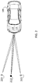
- FIG. 2 shows an exemplary scenario in which ambiguity results in multiple angle of arrival hypotheses that are resolved according to one or more embodiments
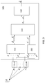
- FIG. 3 details processes performed by a controller to use Doppler measurements to resolve angle of arrival ambiguity according to one or more embodiments.
- phase differences among the receivers of a radar system are used to determine angle of arrival of a target.
- the radar system includes one or more transmitters and two or more receivers that receive the reflections resulting from transmissions by all of the transmitters.
- the transmitters may transmit in turn, according to a time domain multiplexing scheme, or the transmitters may transmit simultaneously, according to a code or frequency multiplexing scheme.
- Each receiver i.e., antenna element that receives reflections or receive element
- receives reflections associated with every transmitter The phase difference between each transmitted signal and each received signal at each receive element is determined and used to estimate angle of arrival of the target to a center of the array of receive elements.
- the difference in measured phase at each of the receive elements rather than difference in phase difference determined at each receive element may be used.
- increased spacing between receivers of the radar system increases the field of view and, thus, increases the angular resolution of the radar system.
- the increased spacing may also result in angle measurement ambiguity in the angle of arrival of the target.
- Embodiments of the systems and methods detailed herein relate to using Doppler measurements to resolve angle of arrival ambiguity of wide aperture radar.
- the Doppler frequency is a function of the carrier signal, velocity of the target, and angle from the target. Because Doppler frequency at each receiver will be affected by the angle from the target to that receiver, Doppler measurements may be used to resolve the angle measurement ambiguity that results from determining the angle based on phase difference among reflections received at each of the receive elements.
- phase differences among the reflected signals received at each of the receive elements are used to measure time difference of arrival of the signals. This time difference is then used to calculate angle of arrival.
- the process can be implemented by beamforming of the received signals.
- beamforming the received signal from each receive element is delayed by a specified amount or weight in order to steer the gain of the energy received by each receive element to a particular angle.
- multiple angle of arrival (AOA) estimates or hypotheses are obtained from the beamforming output with high intensity (e.g. beamforming peaks). The ambiguity results from multiple peaks in the beamforming output, which result from the distance between receive elements. Doppler frequencies are then used to create a metric by which to select among the AOA hypotheses according to one or more embodiments.
- FIG. 1 is a block diagram of a system that uses Doppler measurements to resolve angle of arrival ambiguity of wide aperture radar.
- the system includes a radar system 110 of a vehicle 100 according to the exemplary embodiment shown in FIG. 1 .
- the exemplary vehicle 100 shown in FIG. 1 is an automobile 101 .
- the radar system 110 is shown with a number of transceiver nodes 115 -A through 115 -N (generally referred to as 115 ).
- the radar system 110 is a wide aperture radar. This means that the difference in phase experienced by each receive element of the radar system 110 (at each transceiver node 115 ) can be more than ⁇ , thereby creating ambiguity in the subsequent AOA determination.
- the radar system 110 additionally includes known components to generate the transmitted signals and process the received signals.
- a controller 120 may be part of or coupled to the radar system 110 and may perform some of the known functionality of a radar system 110 such as the signal generation.
- the controller 120 may provide information from the radar system 110 to one or more vehicle systems 130 (e.g., collision avoidance system, adaptive cruise control system, autonomous driving system) to augment or automate vehicle 100 actions.
- vehicle systems 130 e.g., collision avoidance system, adaptive cruise control system, autonomous driving system
- the controller 120 performs the processing, detailed with reference to FIG. 3 , to generate AOA hypotheses and generate metrics, using Doppler frequency determination, for selection among the AOA hypotheses.
- the controller 120 includes processing circuitry that may include an application specific integrated circuit (ASIC), an electronic circuit, a processor (shared, dedicated, or group) and memory that executes one or more software or firmware programs, a combinational logic circuit, and/or other suitable components that provide the described functionality.
- ASIC application specific integrated circuit
- processor shared, dedicated, or group
- memory executes one or more software or firmware programs, a combinational logic circuit, and/or other suitable components that provide the described functionality.
- FIG. 2 shows an exemplary scenario in which ambiguity results in multiple AOA hypotheses that are resolved according to one or more embodiments.
- the vehicle 100 includes the radar system 110 to transmit a signal and receive reflections at every receive element.
- the processing, by the controller 120 of the received reflections results in three hypotheses for AOA associated with three positions. These positions, in turn, are associated with one real target 210 and two ghost targets 215 that result from the ambiguity.
- the controller 120 uses Doppler frequency information, as detailed with reference to FIG. 3 , to resolve the ambiguity and distinguish the real target 210 and its AOA from the ghost targets 215 and their corresponding AOAs.
- FIG. 3 details processes performed by the controller 120 to use Doppler measurements to resolve AOA ambiguity according to one or more embodiments.
- the transceiver nodes 115 -A through 115 -N receive signals reflected from the target 210 .
- each transceiver node 115 includes one receive element.
- each transceiver node 115 may include more than one transmit element and more than one receive element. Because of the distance between the transceiver nodes 115 , the AOA at each transceiver node 115 is different. For example, the AOA at transceiver node 115 -A is different than the AOA at transceiver node 115 -N.
- the AOA ⁇ which is the AOA at the center of the array of receive elements in the array of transceiver nodes 115 , is the angle of interest. This angle ⁇ is resolved by the controller 120 .
- the processes performed by the controller 120 are summarized and then further detailed.
- Each transceiver node 115 -A through 115 -N provides a corresponding measured phase ⁇ 1 through ⁇ N to processing block 310 of the controller 120 , as shown.
- Each transceiver node 115 would provide more than one phase value when each transceiver node 115 includes more than one receive element.
- K AOA hypotheses ⁇ circumflex over ( ⁇ ) ⁇ 1 through ⁇ circumflex over ( ⁇ ) ⁇ K are obtained for the AOA ⁇ .
- the received signals y 1 through y N at the transceiver nodes 115 are also provided for Doppler processing.
- L Doppler frequencies f d 1 through f d L are determined from peaks (e.g., values exceeding a predefined threshold) detected in the Doppler spectrum obtained by performing a fast Fourier transform (FFT) of the received signals y 1 through y N .
- FFT fast Fourier transform
- matching metrics ⁇ 1 through ⁇ K corresponding with AOA hypotheses ⁇ circumflex over ( ⁇ ) ⁇ 1 through ⁇ circumflex over ( ⁇ ) ⁇ K are calculated based on the Doppler frequencies f d 1 through f d L .
- the matching matrices ⁇ 1 through ⁇ K are used to choose the estimated AOA ⁇ circumflex over ( ⁇ ) ⁇ .
- AOA hypotheses ⁇ circumflex over ( ⁇ ) ⁇ 1 , through ⁇ circumflex over ( ⁇ ) ⁇ K are obtained through beamforming.
- Each received signal at each transceiver node 115 is indicated by y i .
- the received signals y i are correlated with a matrix A to obtain the AOA hypotheses ⁇ circumflex over ( ⁇ ) ⁇ 1 through ⁇ circumflex over ( ⁇ ) ⁇ K .
- the matrix A is developed with each column of the matrix being the actual received signals a( ⁇ i ) that would be received at each of the receive elements, in the absence of all noise, for a given AOA ⁇ i at the center point of all the transceiver nodes 115 .
- the number of columns of matrix A corresponds with the number of AOA ⁇ i that are considered, and the number of rows of matrix A corresponds with the number of receive elements among all the transceiver nodes 115 (e.g., N in the exemplary case).
- Each ⁇ i is a function of the phase ⁇ i of the received signal.
- T indicates a transpose
- is the absolute value of a complex scalar a( ⁇ i ) H y.
- the vector z will have a value (an element) for each column of the matrix A, which corresponds to one of the AOA that is considered. Then the AOA hypotheses ⁇ circumflex over ( ⁇ ) ⁇ 1 through ⁇ circumflex over ( ⁇ ) ⁇ K are obtained as elements or values of the z vector that exceed a specified threshold.
- the Doppler spectrum of all the transceiver nodes 115 is examined.
- the L Doppler frequencies f d 1 through f d L correspond with the L Doppler spectrum values that exceed a specified threshold.
- An FFT is performed on the signal received at each receive element over time.
- the transceiver nodes 115 include more than one receive element, the FFT results for all the receive elements within the same transceiver node 115 are combined (e.g., averaged) to determine a Doppler frequency for the transceiver node 115 .
- each transceiver node 115 may determine multiple Doppler frequencies. Assuming a constant relative speed between the target 210 and the radar system 110 , the relationship between the Doppler frequencies and the AOA r, at each transceiver node 115 is given by:
- the Doppler frequencies f d 1 through f d L are denoted as vector f
- the matrix of sine and cosine values is denoted as matrix G ⁇ i
- the vector of velocities is denoted as v.
- the matrix G ⁇ i is denoted based on the relationship, respectively, between through and ⁇ 1 and ⁇ N .
- the power need not necessarily be 2 in EQ. 5, and may instead be a value of power p, where p>0.
- another motion model may be used (e.g., one that does not assume a constant relative speed between the radar system 110 and the target 210 ).
- the other motion model may consider a different mathematical relationship between the frequency vector f and the AOA hypotheses ⁇ i . EQ.
- ⁇ circumflex over (v) ⁇ ( G ⁇ i H G ⁇ i ) ⁇ 1 G ⁇ i H f [EQ. 7]
- H represents the Hermitian transpose.
- the error cost function may not be a squared error cost function (i.e., power may be different than 2).
- the value of p in EQ. 10 need not be 2.
- I is an identity matrix with all the matrix elements on the diagonal having a value of 1 and all other matrix elements having a value of 0.
- the estimated AOA ⁇ circumflex over ( ⁇ ) ⁇ is the AOA hypothesis ⁇ i with the best (i.e., minimal) matching metric ⁇ i .
Landscapes
- Engineering & Computer Science (AREA)
- Remote Sensing (AREA)
- Radar, Positioning & Navigation (AREA)
- Physics & Mathematics (AREA)
- General Physics & Mathematics (AREA)
- Computer Networks & Wireless Communication (AREA)
- Electromagnetism (AREA)
- Radar Systems Or Details Thereof (AREA)
Abstract
Description
Z=∥A H y∥, wherein
H indicates a Hermitian transpose.
wherein
vx and vy are horizontal and vertical velocities of a target generating the received reflections, respectively.
{circumflex over (v)}=minv ∥f−G θ
p represents a power value with p>0.
{circumflex over (v)}=(G θ
μi=∥(I−G θ
wherein p is a power value with p>0, I is an identity matrix, and the selecting the estimated AOA {circumflex over (θ)} is based on identifying a minimal μi.
z=∥A H y∥, wherein
H indicates a Hermitian transpose.
vx and vy are horizontal and vertical velocities of a target generating the received reflections, respectively.
the controller determines:
f=G θ
{circumflex over (v)}=minv ∥f−G θ
p represents a power value with p>0.
{circumflex over (v)}=(G θ
μi=(I−G θ
wherein p is a power value with p>0, I is an identity matrix, and the selecting the estimated AOA {circumflex over (θ)} is based on identifying a minimal μi.
A=[a(θ1)a(θ2) . . . a(θK)] [EQ. 1]
For any received signal y, which is a vector of y1 through yN in the example, the beamforming result vector z is given by:
z=∥A H y∥=[|a(θ1)H y| |a(θ2)H y| . . . |a(θK)H y|]T [EQ. 2]
In EQ. 2, T indicates a transpose, and each |a(θi)Hy| is the absolute value of a complex scalar a(θi)Hy. The vector z will have a value (an element) for each column of the matrix A, which corresponds to one of the AOA that is considered. Then the AOA hypotheses {circumflex over (θ)}1 through {circumflex over (θ)}K are obtained as elements or values of the z vector that exceed a specified threshold.
In EQ. 3, vx and vy are the horizontal and vertical velocities, respectively. The Doppler frequencies fd 1 through fd L are denoted as vector f, the matrix of sine and cosine values is denoted as matrix Gθi, and the vector of velocities is denoted as v. The matrix Gθi is denoted based on the relationship, respectively, between
f=G θ
{circumflex over (v)}=minv ∥f−G θ
{circumflex over (v)}=min[(f−G θ
Further, another motion model may be used (e.g., one that does not assume a constant relative speed between the
EQ. 5 may be re-written as:
{circumflex over (v)}=(G θ
In EQ. 7, H represents the Hermitian transpose. The matching metric μi (μ1 through μK) between the Doppler frequencies (vector f) and AOA hypothesis {circumflex over (θ)}i is given by:
μi =∥f−G θ
EQ. 8 may be re-written as:
μi=∥(I−G θ
In EQ. 8 and EQ. 9, the error cost function may not be a squared error cost function (i.e., power may be different than 2). Thus, EQ. 9 may be written more generally as:
μi=∥(I−G θ
The value of p in EQ. 10 need not be 2. The value of p=2 may be optimal in the case of Gaussian noise while a value p≤1 may be better when the noise distribution is not Gaussian. In EQ. 9 and EQ. 10, I is an identity matrix with all the matrix elements on the diagonal having a value of 1 and all other matrix elements having a value of 0. The estimated AOA {circumflex over (θ)} is the AOA hypothesis θi with the best (i.e., minimal) matching metric μi.
Claims (20)
z=∥A H y∥, wherein
f=G θ
{circumflex over (v)}=minv ∥f−G θ
v=(G θ
μi=∥(I−G θ
z=∥A H y∥, wherein
f=G θ
{circumflex over (v)}=minv ∥f−G θ
{circumflex over (v)}=(G θ
μi=(I−G θ
Priority Applications (3)
| Application Number | Priority Date | Filing Date | Title |
|---|---|---|---|
| US15/679,552 US10690743B2 (en) | 2017-08-17 | 2017-08-17 | Doppler measurements to resolve angle of arrival ambiguity of wide aperture radar |
| CN201810884533.9A CN109407093B (en) | 2017-08-17 | 2018-08-06 | Doppler measurement for resolving ambiguity of angle of arrival of wide aperture radar |
| DE102018119858.2A DE102018119858B4 (en) | 2017-08-17 | 2018-08-15 | Doppler measurements to resolve the angle of incidence ambiguity of wide aperture radar |
Applications Claiming Priority (1)
| Application Number | Priority Date | Filing Date | Title |
|---|---|---|---|
| US15/679,552 US10690743B2 (en) | 2017-08-17 | 2017-08-17 | Doppler measurements to resolve angle of arrival ambiguity of wide aperture radar |
Publications (2)
| Publication Number | Publication Date |
|---|---|
| US20190056506A1 US20190056506A1 (en) | 2019-02-21 |
| US10690743B2 true US10690743B2 (en) | 2020-06-23 |
Family
ID=65235504
Family Applications (1)
| Application Number | Title | Priority Date | Filing Date |
|---|---|---|---|
| US15/679,552 Active 2038-07-27 US10690743B2 (en) | 2017-08-17 | 2017-08-17 | Doppler measurements to resolve angle of arrival ambiguity of wide aperture radar |
Country Status (3)
| Country | Link |
|---|---|
| US (1) | US10690743B2 (en) |
| CN (1) | CN109407093B (en) |
| DE (1) | DE102018119858B4 (en) |
Families Citing this family (12)
| Publication number | Priority date | Publication date | Assignee | Title |
|---|---|---|---|---|
| EP3407085B1 (en) * | 2016-02-29 | 2020-04-08 | Mitsubishi Electric Corporation | Radar device |
| US11073608B2 (en) * | 2018-10-11 | 2021-07-27 | Raytheon Company | Resolving radar angle ambiguities using a multiple hypothesis tracker |
| US11187782B2 (en) * | 2019-04-10 | 2021-11-30 | GM Global Technology Operations LLC | Radar system with enhanced angular resolution and method for enhancing angular resolution in a radar system |
| US11313948B2 (en) * | 2019-07-08 | 2022-04-26 | GM Global Technology Operations LLC | Radar system and method for identifying multiple targets in a beam response spectrum |
| US20210181303A1 (en) * | 2019-12-16 | 2021-06-17 | Semiconductor Components Industries, Llc | Calibrating array antennas based on signal energy distribution as a function of angle |
| US11320515B2 (en) * | 2020-04-21 | 2022-05-03 | GM Global Technology Operations LLC | Detection with multipath reflection elimination in multi-input multi-output radar system |
| WO2021240632A1 (en) * | 2020-05-26 | 2021-12-02 | 三菱電機株式会社 | Direction-of-arrival estimation device |
| WO2022139843A1 (en) * | 2020-12-24 | 2022-06-30 | Intel Corporation | Radar apparatus, system, and method |
| US11991656B2 (en) * | 2021-01-25 | 2024-05-21 | Qualcomm Incorporated | Synchronization signal selection across multiple transceiver nodes |
| EP4033269A1 (en) * | 2021-01-26 | 2022-07-27 | Aptiv Technologies Limited | Methods and system for determining an angle of a detection |
| EP4194885A1 (en) | 2021-12-09 | 2023-06-14 | Aptiv Technologies Limited | Method for determining the mobility status of a target object |
| DE102022205584B4 (en) | 2022-06-01 | 2024-02-29 | Mercedes-Benz Group AG | Method for suppressing mislocations of an angle-resolving radar system based on angle ambiguity |
Citations (6)
| Publication number | Priority date | Publication date | Assignee | Title |
|---|---|---|---|---|
| US5724047A (en) * | 1996-11-27 | 1998-03-03 | Hughes Electronics | Phase and time-difference precision direction finding system |
| US20070052580A1 (en) * | 2004-01-29 | 2007-03-08 | Fiore Paul D | Method and apparatus for improved determination of range and angle of arrival utilizing a two tone cw radar |
| US20080204322A1 (en) * | 2003-11-03 | 2008-08-28 | Gordon Kenneth Andrew Oswald | Determining Positional Information |
| US7804445B1 (en) * | 2006-03-02 | 2010-09-28 | Bae Systems Information And Electronic Systems Integration Inc. | Method and apparatus for determination of range and direction for a multiple tone phased array radar in a multipath environment |
| US20110189962A1 (en) * | 2008-10-06 | 2011-08-04 | Elektrobit System Test Oy | Over-the-air test |
| US20180088224A1 (en) * | 2016-09-26 | 2018-03-29 | Panasonic Corporation | Radar apparatus |
Family Cites Families (6)
| Publication number | Priority date | Publication date | Assignee | Title |
|---|---|---|---|---|
| US5708443A (en) * | 1996-08-07 | 1998-01-13 | Litton Systems Inc. | Method and apparatus for using signal doppler change to resolve long baseline interferometer ambiguous phase change measurements for locating a radar emitter |
| US6727851B2 (en) * | 2000-09-20 | 2004-04-27 | The Corporation Of Mercer University | System for signal emitter location using rotational doppler measurement |
| US9046591B1 (en) * | 2009-05-07 | 2015-06-02 | Sigtem Technology, Inc. | Coordinate-free measurement-domain navigation and guidance using location-dependent radio signal measurements |
| WO2012052856A1 (en) * | 2010-10-21 | 2012-04-26 | Reutech Radar Systems (Proprietary) Limited | Floodlight radar system for detecting and locating moving targets in three dimensions |
| US10539645B2 (en) * | 2016-01-22 | 2020-01-21 | GM Global Technology Operations LLC | Angle of arrival estimation |
| US10705202B2 (en) | 2017-01-19 | 2020-07-07 | GM Global Technology Operations LLC | Iterative approach to achieve angular ambiguity resolution |
-
2017
- 2017-08-17 US US15/679,552 patent/US10690743B2/en active Active
-
2018
- 2018-08-06 CN CN201810884533.9A patent/CN109407093B/en active Active
- 2018-08-15 DE DE102018119858.2A patent/DE102018119858B4/en active Active
Patent Citations (6)
| Publication number | Priority date | Publication date | Assignee | Title |
|---|---|---|---|---|
| US5724047A (en) * | 1996-11-27 | 1998-03-03 | Hughes Electronics | Phase and time-difference precision direction finding system |
| US20080204322A1 (en) * | 2003-11-03 | 2008-08-28 | Gordon Kenneth Andrew Oswald | Determining Positional Information |
| US20070052580A1 (en) * | 2004-01-29 | 2007-03-08 | Fiore Paul D | Method and apparatus for improved determination of range and angle of arrival utilizing a two tone cw radar |
| US7804445B1 (en) * | 2006-03-02 | 2010-09-28 | Bae Systems Information And Electronic Systems Integration Inc. | Method and apparatus for determination of range and direction for a multiple tone phased array radar in a multipath environment |
| US20110189962A1 (en) * | 2008-10-06 | 2011-08-04 | Elektrobit System Test Oy | Over-the-air test |
| US20180088224A1 (en) * | 2016-09-26 | 2018-03-29 | Panasonic Corporation | Radar apparatus |
Also Published As
| Publication number | Publication date |
|---|---|
| CN109407093A (en) | 2019-03-01 |
| DE102018119858B4 (en) | 2024-03-28 |
| CN109407093B (en) | 2022-08-23 |
| US20190056506A1 (en) | 2019-02-21 |
| DE102018119858A1 (en) | 2019-02-21 |
Similar Documents
| Publication | Publication Date | Title |
|---|---|---|
| US10690743B2 (en) | Doppler measurements to resolve angle of arrival ambiguity of wide aperture radar | |
| US11747435B2 (en) | Techniques for angle resolution in radar | |
| US9470782B2 (en) | Method and apparatus for increasing angular resolution in an automotive radar system | |
| US10379204B2 (en) | Method for calibrating a MIMO radar sensor for motor vehicles | |
| US9618616B2 (en) | Radar apparatus | |
| US10389421B2 (en) | Apparatus for estimating arrival-angle and apparatus for beam-forming | |
| US9229100B2 (en) | Phased array radar with monopulse algorithm measurement | |
| CN108333588B (en) | Iterative method for obtaining an angular ambiguity resolution | |
| CN110579763A (en) | Resolving Doppler ambiguity in a multiple-input multiple-output radar using digital multiple-pulse repetition frequency | |
| US10656248B2 (en) | Radar post processing for sidelobe suppression | |
| US20160161604A1 (en) | Improvements in and relating to radar | |
| US20170299694A1 (en) | Antenna specification estimation device and radar device | |
| US20190346548A1 (en) | Filtering to address range walk effect in range-doppler map | |
| CN106486769B (en) | Spatial interpolation method and apparatus for linear phased array antenna | |
| CN109490872B (en) | Single scatterer testing using amplitude and multiple receive elements | |
| JP6362262B2 (en) | Angle estimation apparatus and angle estimation method | |
| US20190383900A1 (en) | Joint optimization of antenna spacing and target angle estimation in a radar system | |
| CN109752699B (en) | Target detection based on curve detection in distance-chirp graph | |
| JP7154494B2 (en) | Direction-of-arrival estimation device and direction-of-arrival estimation method | |
| US11181614B2 (en) | Antenna array tilt and processing to eliminate false detections in a radar system | |
| US10690769B2 (en) | Target angle determination using vehicle radar elements with local reference signals | |
| TWI808874B (en) | Radar system for vehicle and detecting method | |
| US20240094377A1 (en) | High resolution radar simulation to train vehicle radar system neural network | |
| US10948590B2 (en) | Estimation and compensation of transceiver position offsets in a radar system for targets at unknown positions | |
| US20240094376A1 (en) | Doppler radar resolution based on inertial measurement unit of vehicle |
Legal Events
| Date | Code | Title | Description |
|---|---|---|---|
| AS | Assignment |
Owner name: GM GLOBAL TECHNOLOGY OPERATIONS LLC, MICHIGAN Free format text: ASSIGNMENT OF ASSIGNORS INTEREST;ASSIGNOR:BIALER, ODED;REEL/FRAME:043320/0933 Effective date: 20170809 |
|
| STPP | Information on status: patent application and granting procedure in general |
Free format text: DOCKETED NEW CASE - READY FOR EXAMINATION |
|
| STPP | Information on status: patent application and granting procedure in general |
Free format text: NON FINAL ACTION MAILED |
|
| STPP | Information on status: patent application and granting procedure in general |
Free format text: RESPONSE TO NON-FINAL OFFICE ACTION ENTERED AND FORWARDED TO EXAMINER |
|
| STPP | Information on status: patent application and granting procedure in general |
Free format text: FINAL REJECTION MAILED |
|
| STPP | Information on status: patent application and granting procedure in general |
Free format text: NOTICE OF ALLOWANCE MAILED -- APPLICATION RECEIVED IN OFFICE OF PUBLICATIONS |
|
| STPP | Information on status: patent application and granting procedure in general |
Free format text: PUBLICATIONS -- ISSUE FEE PAYMENT VERIFIED |
|
| STCF | Information on status: patent grant |
Free format text: PATENTED CASE |
|
| MAFP | Maintenance fee payment |
Free format text: PAYMENT OF MAINTENANCE FEE, 4TH YEAR, LARGE ENTITY (ORIGINAL EVENT CODE: M1551); ENTITY STATUS OF PATENT OWNER: LARGE ENTITY Year of fee payment: 4 |