JP6362262B2 - Angle estimation apparatus and angle estimation method - Google Patents
Angle estimation apparatus and angle estimation method Download PDFInfo
- Publication number
- JP6362262B2 JP6362262B2 JP2014208417A JP2014208417A JP6362262B2 JP 6362262 B2 JP6362262 B2 JP 6362262B2 JP 2014208417 A JP2014208417 A JP 2014208417A JP 2014208417 A JP2014208417 A JP 2014208417A JP 6362262 B2 JP6362262 B2 JP 6362262B2
- Authority
- JP
- Japan
- Prior art keywords
- signal
- angle
- error
- incident angle
- matrix
- Prior art date
- Legal status (The legal status is an assumption and is not a legal conclusion. Google has not performed a legal analysis and makes no representation as to the accuracy of the status listed.)
- Active
Links
Images
Classifications
-
- G—PHYSICS
- G01—MEASURING; TESTING
- G01S—RADIO DIRECTION-FINDING; RADIO NAVIGATION; DETERMINING DISTANCE OR VELOCITY BY USE OF RADIO WAVES; LOCATING OR PRESENCE-DETECTING BY USE OF THE REFLECTION OR RERADIATION OF RADIO WAVES; ANALOGOUS ARRANGEMENTS USING OTHER WAVES
- G01S13/00—Systems using the reflection or reradiation of radio waves, e.g. radar systems; Analogous systems using reflection or reradiation of waves whose nature or wavelength is irrelevant or unspecified
- G01S13/02—Systems using reflection of radio waves, e.g. primary radar systems; Analogous systems
- G01S13/06—Systems determining position data of a target
- G01S13/42—Simultaneous measurement of distance and other co-ordinates
-
- G—PHYSICS
- G01—MEASURING; TESTING
- G01S—RADIO DIRECTION-FINDING; RADIO NAVIGATION; DETERMINING DISTANCE OR VELOCITY BY USE OF RADIO WAVES; LOCATING OR PRESENCE-DETECTING BY USE OF THE REFLECTION OR RERADIATION OF RADIO WAVES; ANALOGOUS ARRANGEMENTS USING OTHER WAVES
- G01S3/00—Direction-finders for determining the direction from which infrasonic, sonic, ultrasonic, or electromagnetic waves, or particle emission, not having a directional significance, are being received
- G01S3/02—Direction-finders for determining the direction from which infrasonic, sonic, ultrasonic, or electromagnetic waves, or particle emission, not having a directional significance, are being received using radio waves
- G01S3/74—Multi-channel systems specially adapted for direction-finding, i.e. having a single antenna system capable of giving simultaneous indications of the directions of different signals
-
- G—PHYSICS
- G01—MEASURING; TESTING
- G01S—RADIO DIRECTION-FINDING; RADIO NAVIGATION; DETERMINING DISTANCE OR VELOCITY BY USE OF RADIO WAVES; LOCATING OR PRESENCE-DETECTING BY USE OF THE REFLECTION OR RERADIATION OF RADIO WAVES; ANALOGOUS ARRANGEMENTS USING OTHER WAVES
- G01S7/00—Details of systems according to groups G01S13/00, G01S15/00, G01S17/00
- G01S7/02—Details of systems according to groups G01S13/00, G01S15/00, G01S17/00 of systems according to group G01S13/00
- G01S7/40—Means for monitoring or calibrating
- G01S7/4004—Means for monitoring or calibrating of parts of a radar system
- G01S7/4021—Means for monitoring or calibrating of parts of a radar system of receivers
-
- G—PHYSICS
- G01—MEASURING; TESTING
- G01S—RADIO DIRECTION-FINDING; RADIO NAVIGATION; DETERMINING DISTANCE OR VELOCITY BY USE OF RADIO WAVES; LOCATING OR PRESENCE-DETECTING BY USE OF THE REFLECTION OR RERADIATION OF RADIO WAVES; ANALOGOUS ARRANGEMENTS USING OTHER WAVES
- G01S13/00—Systems using the reflection or reradiation of radio waves, e.g. radar systems; Analogous systems using reflection or reradiation of waves whose nature or wavelength is irrelevant or unspecified
- G01S13/88—Radar or analogous systems specially adapted for specific applications
- G01S13/93—Radar or analogous systems specially adapted for specific applications for anti-collision purposes
- G01S13/931—Radar or analogous systems specially adapted for specific applications for anti-collision purposes of land vehicles
Landscapes
- Engineering & Computer Science (AREA)
- Radar, Positioning & Navigation (AREA)
- Remote Sensing (AREA)
- Physics & Mathematics (AREA)
- General Physics & Mathematics (AREA)
- Computer Networks & Wireless Communication (AREA)
- Radar Systems Or Details Thereof (AREA)
Description
本発明は、角度推定装置および角度推定方法に関する。 The present invention relates to an angle estimation device and an angle estimation method.
従来、複数のセンサで受信された対象物からの反射波を復調して生成したベースバンド信号ベクトルを用いて共分散行列を生成し、その部分行列を取り出して当該部分行列から算出した正則行列の固有値を用いて対象物が存在する角度を算出する装置がある(例えば、下記特許文献1参照。)。また、複数のセンサによって受信された到来信号から生成したベースバンド信号(以降、誤解がない場合には単に受信信号と記す)の相関ベクトルを組み合わせて空間平均共分散行列Rを得て、空間平均共分散行列Rによる(RRH)-1(H:複素共役転置)を用いて、角度分布または代数方程式から到来信号の到来方向を推定する装置がある(例えば、下記特許文献2参照。)。 Conventionally, a covariance matrix is generated using a baseband signal vector generated by demodulating reflected waves from an object received by a plurality of sensors, and the partial matrix is extracted from the partial matrix. There is an apparatus that calculates an angle at which an object exists using an eigenvalue (see, for example, Patent Document 1 below). Further, a spatial average covariance matrix R is obtained by combining correlation vectors of baseband signals generated from incoming signals received by a plurality of sensors (hereinafter simply referred to as received signals if there is no misunderstanding) to obtain a spatial average There is an apparatus that estimates an arrival direction of an incoming signal from an angular distribution or an algebraic equation using (RR H ) −1 (H: complex conjugate transpose) based on a covariance matrix R (see, for example, Patent Document 2 below).
しかしながら、従来技術では、正しい推定角度を得るためにセンサも含めた全受信回路の特性を含めて各信号に与える重みを求める操作(キャリブレーション)を行う際、重みの誤差自体の発生を検出することができないという問題がある。キャリブレーションの誤差が発生すると、例えば、実際の受信信号の入射角度に対して推定角度にズレが生じるため、再度のキャリブレーション等を要する。 However, in the prior art, when performing an operation (calibration) for obtaining a weight to be given to each signal including characteristics of all receiving circuits including the sensor in order to obtain a correct estimated angle, the occurrence of the error of the weight itself is detected. There is a problem that can not be. When a calibration error occurs, for example, the estimated angle is deviated from the actual incident angle of the received signal, so that recalibration is required.
1つの側面では、本発明は、キャリブレーション誤差の発生を検出することを目的とする。 In one aspect, the present invention is directed to detecting the occurrence of calibration errors.
本発明の一側面によれば、複数の受信部を含み、前記受信部の受信回路において前記受信部に入射された各信号にキャリブレーションによって設定された重み付けを施し、当該信号に基づいて各信号の入射角度を推定し、前記受信回路の特性に由来する重みの誤差がない状態における前記受信回路の特性を反映したモードベクトルの測定値を保存し、前記誤差がない状態における前記誤差および前記各信号の入射角度に応じて変化する評価値を算出可能な評価関数による前記評価値の算出結果と推定した前記各信号の入射角度とを対応付けて保存し、事後推定した前記各信号の入射角度が、保存した前記各信号の入射角度近傍の値に対応する角度である場合、保存したモードベクトルの測定値と前記評価関数とに基づく評価値を算出し、算出した評価値と保存した評価値との比較に基づいて前記誤差の発生を検出する、角度推定装置および角度推定方法が提案される。 According to one aspect of the present invention, each signal includes a plurality of receiving units, and weights set by calibration are applied to each signal incident on the receiving unit in the receiving circuit of the receiving unit. And the measured value of the mode vector reflecting the characteristics of the receiving circuit in a state where there is no weight error derived from the characteristics of the receiving circuit, and the error in the state without the error and the respective errors A calculation result of the evaluation value by an evaluation function that can calculate an evaluation value that changes according to the incident angle of the signal is stored in association with the estimated incident angle of each signal, and the post-estimated incident angle of each signal is stored. Is an angle corresponding to a value near the incident angle of each stored signal, an evaluation value based on the measured value of the stored mode vector and the evaluation function is calculated and calculated. Detecting the occurrence of the error based on the comparison between the evaluation value and the saved evaluation value, angle estimation device and the angle estimation method is proposed.
本発明の一態様によれば、キャリブレーション誤差の発生を検出することができる。 According to one embodiment of the present invention, occurrence of a calibration error can be detected.
以下に図面を参照して、開示技術の好適な実施の形態1〜4を詳細に説明する。 Hereinafter, preferred embodiments 1 to 4 of the disclosed technology will be described in detail with reference to the drawings.
(実施の形態1)
(角度推定装置の機能的構成)
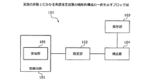
図1は、実施の形態1にかかる角度推定装置の機能的構成の一例を示すブロック図である。角度推定装置100は、超音波、電波、光、などを用いて、物体を捜索、探知、測距または測角する装置に用いられる。具体的には、角度推定装置100は、ソナーやレーダなどに用いられる。角度推定装置100は、受信回路101と、推定部102と、保存部103と、検出部104と、を有する。受信回路101は、複数の受信部105と、複数の受信部105によって受信された各信号を増幅する不図示のアンプを含む。受信部105は、例えば、センサアレイ、アンテナなどである。
(Embodiment 1)
(Functional configuration of angle estimation device)
FIG. 1 is a block diagram of an example of a functional configuration of the angle estimation apparatus according to the first embodiment. The
受信回路101は、例えばアンプ、ミキサ、フィルタ、A/D(Analog to Digital)コンバータ、およびSPU(Signal Processing Unit)等を含む。受信回路101は、キャリブレーションによって設定された重みを用いて複数の受信部105に入射された各信号を重み付けする。各信号は、不図示の送信部から送信されて目標物によって反射された信号である。キャリブレーションは、例えば工場出荷時などに行われる。
The
推定部102は、受信回路101によって重み付けされた各信号に基づいて各信号の入射角度を推定する。保存部103は、受信回路101の特性に対する重みの誤差(以下「キャリブレーション誤差」という)がない状態における受信回路101の特性を反映したモードベクトル(エラーフリーモードベクトル)の測定値を保存する。また、保存部103は、キャリブレーション誤差がない状態における、評価関数による評価値(参照値)の算出結果と推定部102による各信号の入射角度とを対応付けて保存する。
The
評価関数は、キャリブレーション誤差および各信号の入射角度に応じて変化する評価値を算出可能な関数である。保存部103は、キャリブレーション誤差がない状態における、例えば入射角度1°の場合におけるモードベクトルの測定値と、評価関数による評価値の算出結果(上記参照値)と、推定部102によって推定された入射角度1°と、を対応付けて保存する。なお、キャリブレーション誤差がない状態における、例えば入射角度1°の場合における(エラーフリー)モードベクトルの測定値を、以降、誤解が無い場合には単にモードベクトルの測定値と記す。また、保存部103は、複数の入射角度に対応する評価値の算出結果と、複数の入射角度とを対応付けて保存してもよい。
The evaluation function is a function that can calculate an evaluation value that changes according to the calibration error and the incident angle of each signal. The
検出部104は、推定部102によって推定された各信号の入射角度が、保存部103によって保存された各信号の入射角度近傍の値に対応する角度である場合、保存部103によって保存されたモードベクトルの測定値と評価関数とに基づく評価値を算出する。例えば、保存部103によって保存された各信号の入射角度近傍の値に対応する角度は、保存部103によって保存された各信号の入射角度と同じ角度でもよいし、その近傍の角度でもよい。例えば、保存部103によって保存された各信号の入射角度1°に対応する入射角度は、1°またはその近傍の角度である。近傍の具体的定義は、装置の角度推定の分解能に対して、例えば、数σ程度とする。ここでいうσは、雑音電力ではなく、角度を示す値である。
When the incident angle of each signal estimated by the
検出部104は、保存部103によって保存された各信号の入射角度に対応する入射角度と、モードベクトルの測定値と、評価関数と、に基づいて評価値(算出値)を算出する。また、検出部104は、算出した評価値と保存部103によって保存された評価値(参照値)との比較に基づいてキャリブレーション誤差の発生を検出する。検出部104は、例えば、算出した評価値と保存部103によって保存された評価値との比率によってキャリブレーション誤差の発生を検出する。例えば、検出部104は、算出した評価値と保存部103によって保存された評価値との比が1とは異なる場合にキャリブレーション誤差の発生を検出する。
The
また、推定部102は、複数の受信部間における各信号の空間位相差に基づいて各信号の入射角度を推定する。具体的には、推定部102は、ESPRIT(Estimation of Signal Parameters via Rotational Invariance Techniques)法により各信号の入射角度を推定する。
Moreover, the
また、推定部102は、受信回路101によって重み付けされた各信号の共分散行列を計算し、スペクトラム走査処理に基づいて各信号の入射角度を推定する。スペクトラムの走査処理に基づいて入射角度を推定する手法は、Capon法、MUSIC(MUltiple SIgnal Classification)法、プリズム法およびLP(Linear Prediction)法などが挙げられる。
Further, the
(角度推定装置の構成の一例)
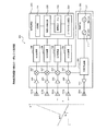
図2は、角度推定装置の構成の一例を示す説明図である。角度推定装置100は、発振回路201と、方向性結合器202と、パワーアンプ203と、送信アンテナ204と、受信アンテナ205と、ローノイズアンプ206と、ミキサ207と、A/D変換器208と、信号処理部209と、を有する。なお、ミキサ207とA/D変換器208との間には通常LPF(Low Pass Filter)等のベースバンド回路が入るが、説明を簡単にするため、これらのコンポーネントについては割愛した。
(An example of the configuration of the angle estimation device)
FIG. 2 is an explanatory diagram illustrating an example of the configuration of the angle estimation apparatus. The
発振回路201は、RF−VCO(Radio Frequency−Voltage Controlled Oscillator)111と、BB−OSC(Base Band−Oscillator)112と、を有する。RF−VCO111は、電圧により発振周波数を制御する発振器である。BB−OSC112は、RF−VCO111に変調用信号を加えて周波数変調を施すことによって、FMCW(Frequency Modulated Continuous Wave)信号を得て、FMCW信号を方向性結合器202へ出力する。
The
方向性結合器202は、発振回路201から出力された信号をパワーアンプ203およびミキサ207へ出力する。パワーアンプ203は、方向性結合器202から出力された信号を電力増幅して送信アンテナ204へ出力する。送信アンテナ204は、M個(ここでは1個)のセンサ素子を有する送信用センサアレイである。送信アンテナ204は、パワーアンプ203から出力された信号をプローブ信号として目標探知範囲に放射する。
The
受信アンテナ205は、N個(ここでは4個)のセンサ素子を有する受信用センサアレイである。受信アンテナ205は、送信アンテナ204から送信されて、例えば先方車両等の目標物体で反射された反射信号を受信する。受信アンテナ205は、受信した信号をローノイズアンプ206へ出力する。ローノイズアンプ206は、受信アンテナ205から出力された信号を増幅し、ミキサ207へ出力する。ミキサ207は、ローノイズアンプ206から出力された信号と、方向性結合器202から出力された信号とをミキシングし、ミキシングした信号をA/D変換器208へ出力する。
The reception antenna 205 is a reception sensor array having N (here, four) sensor elements. The receiving antenna 205 receives a reflected signal transmitted from the transmitting
A/D変換器208は、ミキサ207から出力されたアナログ信号をデジタル信号に変換して、信号処理部209へ出力する。信号処理部209は、推定部221と、角度行列再生部222と、参照値テーブル223と、スペクトラム比較部224と、を有する。推定部221は、A/D変換器208から出力された信号を用いて周知の手法で目標の距離、速度、角度等を推定し、推定結果を角度行列再生部222へ出力する。
The A /
角度行列再生部222は、推定部221から出力された推定結果を用いて角度行列を再生し、参照値テーブル223およびスペクトラム比較部224へ出力する。参照値テーブル223は、エラーフリーモードベクトルや角度行列再生部222から出力された角度行列を記録したり、キャリブレーションの異常を判定するための参照値を更新したりする。スペクトラム比較部224は、角度行列再生部222から出力された行列と、参照値テーブル223に記録されている参照値と、を比較してキャリブレーション誤差の有無を判定する。
The angle
図1に示した受信部105は、例えば受信アンテナ205によって実現される。また、図1において説明した受信回路101は、例えばローノイズアンプ206、ミキサ207によって実現される。
The receiving
(信号処理部のハードウェア構成の一例)
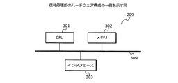
図3は、信号処理部のハードウェア構成の一例を示す図である。図3に示すように、信号処理部209は、CPU(Central Processing Unit)301と、メモリ302と、インタフェース303と、を備えている。CPU301、メモリ302およびインタフェース303は、バス309によって接続されている。
(Example of hardware configuration of signal processor)
FIG. 3 is a diagram illustrating an example of a hardware configuration of the signal processing unit. As shown in FIG. 3, the
CPU301は、信号処理部209の全体の制御を司る。メモリ302には、例えばメインメモリおよび補助メモリが含まれる。メインメモリは、例えばRAM(Random Access Memory)である。メインメモリは、CPU301のワークエリアとして使用される。補助メモリは、例えば磁気ディスク、光ディスク、フラッシュメモリなどの不揮発メモリである。補助メモリには、信号処理部209を動作させる各種のプログラムが記憶されている。補助メモリに記憶されたプログラムは、メインメモリにロードされてCPU301によって実行される。
The
インタフェース303は、ユーザインタフェースや通信インタフェースを含む。ユーザインタフェースは、例えば、ユーザからの操作入力を受け付ける入力デバイスや、ユーザへ情報を出力する出力デバイスなどを含む。また、通信インタフェースは、例えば、無線や有線によって信号処理部209の外部装置との間で通信を行うインタフェースである。インタフェース303は、CPU301によって制御される。
The
図1に示した、推定部102と、保存部103と、検出部104とは、メモリ302に記憶されたプログラムをCPU301に実行させることにより、その機能を実現する。なお、装置構成によっては受信回路101を制御する場合もある。また、図2に示した、推定部221と、角度行列再生部222と、スペクトラム比較部224とは、メモリ302に記憶されたプログラムをCPU301に実行させることにより、その機能を実現する。また、図1に示した保存部103と、図2に示した参照値テーブル223は、メモリ302によってその機能を実現する。
The
(角度推定装置を車両のレーダ装置に適用した場合の一例)
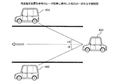
図4は、角度推定装置を車両のレーダ装置に適用した場合の一例を示す説明図である。図4に示すように、車両400に搭載されるレーダ装置は、前方の車両401,402を探知して測距する。例えば、車両401は、車両400の前方の角度+θ方向に位置している。車両402は、車両400の前方の角度−θ方向に位置している。
(An example of applying the angle estimation device to a vehicle radar device)
FIG. 4 is an explanatory diagram showing an example in which the angle estimation device is applied to a vehicle radar device. As shown in FIG. 4, the radar device mounted on the
レーダ装置は、プローブ信号を前方の目標探知範囲に放射し、車両401,402に反射されて戻ってきた反射信号を受信し、反射信号の到来角度(入射角度)を推定する。ここで、本願に開示のレーダ装置(角度推定装置100)は、角度推定の際に用いるキャリブレーション(重み)の値に誤差が発生しているか否かを検出する。
The radar apparatus radiates the probe signal to the front target detection range, receives the reflected signal reflected by the
(信号処理部による角度推定の原理について)
図2に戻り、信号処理部209による角度推定の原理について説明する。説明を簡単にするため、送信アンテナ204の数Mを1とし、受信アンテナ205の数Nを4とする。受信アンテナ205はX軸上に等しい間隔dで直線状に配置されているものとする。なお、このような受信アンテナ205をULA(Uniform Linear Array)という。
(About the principle of angle estimation by the signal processor)
Returning to FIG. 2, the principle of angle estimation by the
探知範囲にK個の目標が存在し、送信アンテナ204から送信されたプローブ信号が各目標によって反射されると、この反射されたRFエコー信号を受信アンテナ205が受信する。RFエコー信号は、アレイ軸の垂線方向(Y軸)を0基準として、互いに異なる角度θkで入射してくるものとする。つまり、エコー信号がその到来方向を推定すべき信号であり、エコー信号の到来方向が目標の角度ということになる。
When there are K targets in the detection range and the probe signal transmitted from the
このとき、n番目のアンテナで受信されたRFエコー信号とプローブ信号とをミキシングおよび復調して得られたエコー信号vn(t)は、1番目の受信アンテナ205を位相基準とした場合、下記(1)式によって表すことができる。また、空間位相φは、下記(2)式によって表すことができる。なお、gn(θk)はn番目のアンテナ素子の特性、xk(t)はベースバンド信号、nn(t)は雑音信号、φn,kは素子1を基準にしたときの素子nにおける第m波の受信位相、λは搬送波の波長、jは虚数単位、tは時間を示す。 At this time, the echo signal v n (t) obtained by mixing and demodulating the RF echo signal and the probe signal received by the nth antenna is as follows when the first receiving antenna 205 is used as a phase reference. (1) It can represent with Formula. Further, the spatial phase φ can be expressed by the following equation (2). Note that g n (θ k ) is the characteristic of the n-th antenna element, x k (t) is a baseband signal, n n (t) is a noise signal, and φ n, k is an element with element 1 as a reference. The reception phase of the m-th wave at n, λ is the wavelength of the carrier wave, j is an imaginary unit, and t is time.

これをベクトルとして書き下せば下記(3)式が得られる。 If this is written as a vector, the following equation (3) is obtained.
ただし、下記(4)式、(5)式および(6)式に示す関係がある。 However, there is a relationship shown in the following expressions (4), (5), and (6).
![]()
![]()
![]()
![]()
上記(3)〜(6)式において、v(t)は出力信号ベクトルを示し、x(t)はベースバンドベクトルを示し、n(t)は雑音ベクトルを、a(θk)はモードベクトル(方向ベクトル)を示し、Tは転置を示す。 In the above expressions (3) to (6), v (t) represents an output signal vector, x (t) represents a baseband vector, n (t) represents a noise vector, and a (θ k ) represents a mode vector. (Direction vector) and T indicates transposition.
そして、x(t)とn(t)との間に相関がないものとして、上記(3)式からv(t)の共分散行列を計算すると、下記(7)式が得られる。 Then, assuming that there is no correlation between x (t) and n (t) and calculating the covariance matrix of v (t) from the above equation (3), the following equation (7) is obtained.
![]()
![]()
これがアレイアンテナを用いて目標の角度推定を行う場合の基本的な演算対象となる。具体的には、Rvvが到来方向の推定の基本的な対象式となる。上記(7)式において、RvvはN×N次元の共分散行列である。また、上記(7)式において、E{・}は期待値(アンサンブルまたは時間平均)を表し、Hは複素共役転置を表し、Iは単位行列を表し、σ2は雑音ベクトルn(t)の分散(雑音電力)を表し、σ2Iは雑音ベクトルの共分散行列を表す。ただし、Rxxは下記(8)式で定義されるベースバンド信号の共分散行列である。 This is a basic calculation target when the target angle is estimated using the array antenna. Specifically, R vv is a basic target expression for estimating the direction of arrival. In the above equation (7), R vv is an N × N-dimensional covariance matrix. In the above equation (7), E {·} represents an expected value (ensemble or time average), H represents a complex conjugate transpose, I represents a unit matrix, and σ 2 represents the noise vector n (t). It represents the variance (noise power), and σ 2 I represents the covariance matrix of the noise vector. R xx is a baseband signal covariance matrix defined by the following equation (8).
上記(8)式において、RxxはK×K次元のベースバンド信号の共分散行列となる。以下において、時刻tを省略する。 In the above equation (8), R xx is a covariance matrix of a K × K dimensional baseband signal. In the following, time t is omitted.
ここで、エコー信号は、同じ信号源からの送信信号が目標によって反射されてきたものであるから本質的にコヒーレントである。そのため、共分散行列の階数(以下、rank)と目標数Kとの関係は下記(9)式のようになる。 Here, the echo signal is essentially coherent because the transmission signal from the same signal source has been reflected by the target. Therefore, the relationship between the rank of the covariance matrix (hereinafter, rank) and the target number K is expressed by the following equation (9).
![]()
![]()
θをパラメータとして生成される角度ベクトルa(θ)は、下記(10)式によって表すことができる。 The angle vector a (θ) generated using θ as a parameter can be expressed by the following equation (10).
例えば、Capon法においてRvvの逆行列Rvv -1と、上記(10)式を用いて下記(11)式の角度スペクトルPCapon(θ)を定義することができる。パラメータθを変更しながらPCapon(θ)を計算し、これがピークを示すθの値をもって目標の角度情報として採用することができる。 For example, it can be defined as the inverse matrix R vv -1 of R vv in Capon method, the (10) below (11) by using the equation of angular spectrum P Capon a (theta). P Capon (θ) is calculated while changing the parameter θ, and the value of θ indicating the peak can be used as target angle information.
しかし、上記(9)式を参照すると明らかなように、行列Rvvは逆行列をもたない。そのため、一般にはRvvのrankを回復するために空間平均という処理を施した上で、逆行列や固有値から角度推定を行う(なお、空間平均後のRvvもRvvと書く)。以下にその技術を簡単に説明する。 However, as apparent from the above equation (9), the matrix R vv does not have an inverse matrix. Therefore, generally after applying a process of spatial average to recover the rank of R vv, it performs angle estimation from the inverse matrix and the eigenvalues (Also R vv after spatial averaging and writing R vv). The technique will be briefly described below.
(a)前方空間平均:Rvvの主対角線方向に沿ってQ×Qの部分行列をとり(N−Q+1個できる)、これらを足し合わせて平均する。 (A) Forward spatial average: Q × Q sub-matrices are taken along the main diagonal direction of R vv (N−Q + 1), and these are added together and averaged.
(b)後方空間平均:アレイの基準点を反転させて、上記(a)と同様の操作が行われる。 (B) Back space average: The same operation as in (a) above is performed by inverting the reference point of the array.
(c)前後方空間平均:上記(a)、(b)を組み合わせた手法であり、通常用いられる。 (C) Front-rear space average: A method combining the above (a) and (b), and is usually used.
空間平均を用いることにより、Rvvのrankは回復するので、角度スペクトルPCapon等を用いて目標角度の推定は可能になる。しかしながら、例えば上記(a)からも明らかなようにRvvから部分行列を取り出して、平均処理をかけるということは、目標角度の推定精度に上記(4)式の各素子アンテナの特性gn(θk)が、加算的な形で反映されてしまうことを意味する。 Since the rank of R vv is restored by using the spatial average, the target angle can be estimated using the angle spectrum P Capon or the like. However, for example, as is clear from (a) above, taking out the submatrix from R vv and applying the average processing means that the estimation accuracy of the target angle has the characteristics g n ( θ k ) is reflected in an additive manner.
そこで、このような影響を避けるため、レーダ視野角(FOV:Field Of View)内で全ての素子アンテナの特性が概ね一定値となるように補正処理(キャリブレーション)を施しておく。具体的には、いくつか既知の角度に目標をおいて角度推定を行い、真値と推定値との差を最小化するようにgn(θk)への補正係数を定める。これにより、キャリブレーション後の角度行列を、下記(12)式のように表すことができる。 Therefore, in order to avoid such an influence, correction processing (calibration) is performed so that the characteristics of all the element antennas become substantially constant values within the radar viewing angle (FOV: Field Of View). Specifically, angle estimation is performed with several known angles as targets, and a correction coefficient for g n (θ k ) is determined so as to minimize the difference between the true value and the estimated value. Thereby, the angle matrix after calibration can be expressed as in the following equation (12).
この状態で任意の手法で角度推定を行えば、その手法の最良の精度での推定値が得られる。ところが、装置を実際に利用している間にハードウェアの経時変化等によりキャリブレーション値がずれると、各受信アンテナ205への着信信号の振幅や位相が変化した結果が得られる。キャリブレーション値がずれる主な原因は、受信アンテナ205そのものの特性変化というよりも、後段のRF回路の特性変化であり、キャリブレーション誤差Cは下記(13)式のようにモデル化できる。 If angle estimation is performed by an arbitrary method in this state, an estimated value with the best accuracy of the method can be obtained. However, if the calibration value is shifted due to a change in hardware over time while the apparatus is actually used, a result in which the amplitude or phase of the incoming signal to each receiving antenna 205 is changed is obtained. The main cause of the deviation of the calibration value is not the characteristic change of the receiving antenna 205 itself, but the characteristic change of the subsequent RF circuit, and the calibration error C can be modeled as the following equation (13).
すなわち、最初にキャリブレーションを行った後にキャリブレーション誤差が発生したときの受信信号w(t)は、下記(14)式のように表すことができる。 That is, the received signal w (t) when a calibration error occurs after the initial calibration can be expressed as the following equation (14).
![]()
![]()
(ESPRIT法による推定結果について)
ここで、ESPRIT法による推定結果について説明する。上述したように、このような状態で角度推定を行うと、推定値には誤差が含まれる。ここで、図5を用いて、Q(Quick)−ESPRIT法で角度推定を行った場合の計算結果について説明する。なお、Q−ESPRIT法は、例えば、特開2012−103132号公報に記載の「高速化ESPRIT法」と同様の手法である。
(Estimated results by ESPRIT method)
Here, the estimation result by the ESPRIT method will be described. As described above, when angle estimation is performed in such a state, an error is included in the estimated value. Here, the calculation result when the angle is estimated by the Q (Quick) -ESPRIT method will be described with reference to FIG. The Q-ESPRIT method is, for example, the same method as the “high-speed ESPRIT method” described in JP 2012-103132 A.
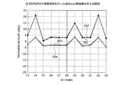
図5は、Q−ESPRIT法で角度推定を行った場合の計算結果を示す説明図である。図5において、横軸は距離(bin index)、縦軸は推定角度(Estimated Azimuth)を示している。例えば、距離20m(28bin)であり、角度±3°の位置に、速度0km/hの2つの目標が存在するものとする。なお、図5の横軸の単位「bin」は、FFT(Fast Fourier Transform)の区切り(インデックス)を示しており、距離に相当する。28binは、例えば、距離20mに相当する。 FIG. 5 is an explanatory diagram showing calculation results when angle estimation is performed by the Q-ESPRIT method. In FIG. 5, the horizontal axis indicates the distance (bin index), and the vertical axis indicates the estimated angle (Estimated Azimuth). For example, it is assumed that there are two targets having a distance of 20 m (28 bin) and a speed of 0 km / h at an angle of ± 3 °. Note that the unit “bin” on the horizontal axis in FIG. 5 indicates an FFT (Fast Fourier Transform) delimiter (index) and corresponds to a distance. 28 bin corresponds to a distance of 20 m, for example.
図5において、実線(グラフ501,503)は、キャリブレーション誤差がない場合の計算結果を示している。また、点線(グラフ502,504)は、受信アンテナ205b,205cに−0.75dBのキャリブレーション誤差が発生した場合の計算結果を示している。
In FIG. 5, solid lines (
具体的には、グラフ501は、キャリブレーション誤差がない場合の角度+3°の位置の目標に対する計算結果を示している。グラフ502は、キャリブレーション誤差が発生した場合の角度+3°の位置の目標に対する計算結果を示している。グラフ503は、キャリブレーション誤差がない場合の角度−3°の位置の目標に対する計算結果を示している。グラフ504は、キャリブレーション誤差が発生した場合の角度−3°の位置の目標に対する計算結果を示している。図5の28binにおけるグラフ501,502(またはグラフ503,504)間の角度の相違に示すように、わずか0.75dBのキャリブレーション誤差が発生しただけで0.5°程度の推定誤差が生じることがわかる。
Specifically, the
(PRISM法およびMUSIC法による推定結果について)
次に、PRISM法およびMUSIC法による推定結果について説明する。
(About estimation results by PRISM method and MUSIC method)
Next, estimation results by the PRISM method and the MUSIC method will be described.
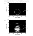
図6は、目標が2つ存在する場合の角度スペクトラムを角度と距離に対して示した説明図である。図6において、図5と同様に、例えば、距離20m(28bin)、角度±3°の位置に、速度0km/hの2つの目標が存在するものとする。図6の(a)はPRISM法を用いて計算した角度スペクトラムである。また、図6の(b)はMUSIC法(FBSS(前後方空間平均)−MUSIC法)を用いて計算した角度スペクトラムである。図6の(a)、(b)の横軸は角度を示し、縦軸は距離を示している。 FIG. 6 is an explanatory diagram showing the angle spectrum with respect to the angle and distance when there are two targets. In FIG. 6, as in FIG. 5, it is assumed that there are two targets at a speed of 0 km / h, for example, at a distance of 20 m (28 bin) and an angle of ± 3 °. FIG. 6A shows an angular spectrum calculated using the PRISM method. Moreover, (b) of FIG. 6 is an angle spectrum calculated using the MUSIC method (FBSS (front and rear space average) -MUSIC method). 6A and 6B, the horizontal axis indicates the angle, and the vertical axis indicates the distance.
図6の(a)、(b)において、角度スペクトラムが仮定した2つの目標位置に集約している場合、つまり、角度スペクトラムが2つの目標付近で点状に表示されているほど、高い精度で目標の到来方向が推定されていることを示している。図6の(a)の領域601において、横軸が±3°、縦軸が28binの付近に、角度スペクトラムが表示されている。また、図6の(b)の領域602においても、横軸が±3°、縦軸が28binの付近に、角度スペクトラムが表示されている。
In FIGS. 6A and 6B, when the angle spectrum is aggregated at two assumed target positions, that is, as the angle spectrum is displayed in the form of dots in the vicinity of the two targets, the accuracy is higher. It shows that the direction of arrival of the target is estimated. In an
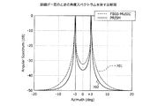
図6では、誤差の発生が把握しづらいので、図7に目標の存在する距離において図6の角度スペクトラム(a)、(b)を紙面上部から下部へ輪切りにし、横軸に角度(図6と同様)、縦軸にスペクトラム(図6のZ軸相当)を取って書き直したものを示す。図7は、距離が一定のときの角度スペクトラムを示す説明図である。図7において、グラフ701,702は、レーダから20m離れた±3°の位置に、2つのターゲットを置いた場合の、各手法による計算結果を示している。具体的には、グラフ701は、MUSIC法による計算結果を示している。グラフ702は、PRISM法による計算結果を示している。グラフ701,702のいずれも、ピークが±3°の位置からずれており、推定誤差が生じていることがわかる。
In FIG. 6, since it is difficult to grasp the occurrence of an error, the angle spectrums (a) and (b) of FIG. 6 are cut from the upper part to the lower part of the drawing at the distance where the target exists in FIG. And the vertical axis represents the spectrum (corresponding to the Z axis in FIG. 6) and rewritten. FIG. 7 is an explanatory diagram showing an angle spectrum when the distance is constant. In FIG. 7,
(評価関数f(C,θ)について)
ここで、装置を運用している最中に信号処理でキャリブレーション誤差の発生を検出するためには、角度θに対する値がキャリブレーション誤差Cだけに反応して変化する評価関数f(C,θ)を用いる。一方、出荷時のキャリブレーションを行った後、エラーフリーモードベクトルa0(θ)の測定値、および、FOV(レーダ視野角)内の複数の角度θm(m=1〜M)に対する評価関数の計算値(参照値f(I,θm))をそれぞれ保存しておく。
(Evaluation function f (C, θ))
Here, in order to detect the occurrence of a calibration error by signal processing during the operation of the apparatus, the evaluation function f (C, θ) in which the value for the angle θ changes only in response to the calibration error C. ) Is used. On the other hand, after calibration at the time of shipment, the measured value of the error-free mode vector a 0 (θ) and the evaluation function for a plurality of angles θ m (m = 1 to M) in the FOV (radar viewing angle) The calculated values (reference values f (I, θ m )) are respectively stored.
そして、動作中に角度θmの近傍の角度出力θkが得られた場合、評価関数f(C,θ)の算出値f(C,θk)を算出して、参照値f(I,θm)と比較を行い、この相違が事前に定めておいた閾値を超えた場合にキャリブレーション誤差が発生したものと判定する。なお、評価関数f(C,θ)において、キャリブレーション誤差Cの値自体は、入力されないし、導出もされない。キャリブレーション誤差が発生した場合は、警告を発したり、補正操作を試みたりすればよい。 When the angle output θ k near the angle θ m is obtained during the operation, the calculated value f (C, θ k ) of the evaluation function f (C, θ k ) is calculated, and the reference value f (I, I, θ m ), and if this difference exceeds a predetermined threshold value, it is determined that a calibration error has occurred. In the evaluation function f (C, θ), the value of the calibration error C itself is not input or derived. If a calibration error occurs, a warning may be issued or a correction operation may be attempted.
実施の形態1では、Q−ESPRIT法を用いた場合の評価関数の導出法について説明する。まず、キャリブレーション誤差が発生した状態の受信信号ベクトルをwとし、下記(15)式のように部分ベクトルを取得する(上記(14)式参照)。なお、以降の記述においては説明を簡単にするため雑音成分を無視する。 In the first embodiment, a method for deriving an evaluation function when the Q-ESPRIT method is used will be described. First, a received signal vector in a state where a calibration error has occurred is set to w, and a partial vector is obtained as shown in the following equation (15) (see the above equation (14)). In the following description, the noise component is ignored for the sake of simplicity.
ここでは受信アンテナ205の数を4としているので、w1、w2は、サブアレイ(受信アンテナ205a〜205c)、(受信アンテナ205b〜205d)からの信号である。次に、Cの要素が極端に1から外れていなければ、ESPRIT法の大前提である2つのサブアレイ間に下記(16)式の回転不変関係が成り立つ。
Here, since the number of receiving antennas 205 is 4, w 1 and w 2 are signals from the subarrays (receiving
これにより、J1CA0が以下の様にQR分解されたとすれば、上記(16)式は下記(17)式のように書き換えられる。 Accordingly, if J 1 CA 0 is subjected to QR decomposition as follows, the above equation (16) is rewritten as the following equation (17).
![]()
![]()
ここで次の2つの行列からU1 -1U2を計算して固有値分解すると、下記(18)式に示すように、VとΩが求まる。 Here, when U 1 −1 U 2 is calculated from the following two matrices and eigenvalue decomposition is performed, V and Ω are obtained as shown in the following equation (18).
以上が、キャリブレーション誤差が存在する場合のQ−ESPRIT法のアルゴリズムである。 The above is the algorithm of the Q-ESPRIT method when there is a calibration error.
(Q−ESPRIT法による評価関数について)
Q−ESPRIT法における評価関数は以下のように導出することができる。上記(17)式および(18)式を参照すると、下記(19)式に示すように、キャリブレーション誤差を含む角度行列CAが再生できることがわかる。ただし、簡単に予想できることであるから説明については割愛するが、ここで示した誤差を含んだ角度行列の表記は一例である。
(Evaluation function by Q-ESPRIT method)
The evaluation function in the Q-ESPRIT method can be derived as follows. Referring to the equations (17) and (18), it can be seen that the angle matrix CA including the calibration error can be reproduced as shown in the following equation (19). However, the description is omitted because it can be easily predicted, but the notation of the angle matrix including the error shown here is an example.
エラーフリーモードベクトルa0(θ)と上記(19)式とを用いることにより、下記(20)式に示す評価関数f(C,θ)を得ることができる。ここで、下記(20)式に示す評価関数f(C,θ)は、図1の推定部102において角度推定を行う際に得られる所定の行列U1 -1U2(上記(18)式参照)を固有値分解した複数の行列V,Ωの組み合わせに基づく行列Wを用いて表される関数である。なお、Q−ESPRIT法では、rank(Rvv)=N−1と固定して角度推定を行うので、N=4であれば常に3個の推定角度が得られる。
By using the error free mode vector a 0 (θ) and the above equation (19), the evaluation function f (C, θ) shown in the following equation (20) can be obtained. Here, the evaluation function f (C, θ) shown in the following equation (20) is a predetermined matrix U 1 −1 U 2 (the above equation (18) obtained when the
目標の角度としてθkなる推定値が得られた場合、上記(20)式を用いてθkに対応する評価関数f(C,θ)の値f(C,θk)を算出する。そして、算出した値f(C,θk)と参照値f(I,θm)と、を比較して、差分や比率などの相違が、予め定めた閾値を超えた場合にキャリブレーション誤差が発生したものと判定することができる。つまり、キャリブレーション誤差のない状態で計算・保存しておいた角度θmに対する評価関数の基準値f(I,θm)(Iは単位行列)と、θm近傍の到来角度θkの検出時に計算した評価関数の値f(C,θk)とを比較する。 If estimates theta k becomes as the angle of the target is obtained, it calculates the evaluation function f (C, theta) corresponding to theta k by using the expression (20) the value f (C, theta k) of the. Then, the calculated value f (C, θ k ) is compared with the reference value f (I, θ m ), and if a difference such as a difference or a ratio exceeds a predetermined threshold, a calibration error occurs. It can be determined that it has occurred. That is, the reference value f (I, θ m ) (I is a unit matrix) of the evaluation function with respect to the angle θ m calculated and stored without calibration error, and detection of the arrival angle θ k near θ m The value f (C, θ k ) of the evaluation function calculated at times is compared.
評価関数f(C,θ)は、到来角度とキャリブレーション誤差とに反応するから、f(I,θm)とf(C,θk)とを比較することによりキャリブレーション誤差の発生を検出できる。なお、参照値f(I,θm)は、算出値f(C,θk)と同様に、Q−ESPRIT法によって算出された値である。 Since the evaluation function f (C, θ) reacts to the arrival angle and the calibration error, the occurrence of the calibration error is detected by comparing f (I, θ m ) and f (C, θ k ). it can. The reference value f (I, θ m ) is a value calculated by the Q-ESPRIT method, similarly to the calculated value f (C, θ k ).
(キャリブレーション誤差の振幅成分の推定について)
上記(20)式から、明らかに下記(21)式が成り立つ。キャリブレーション誤差の大きさは、行列:C(A0A0 H)CHの対角要素とエラーフリーモードベクトルa0(θk)とを用いて推定される。ここで、図1に示した検出部104は、上記(20)式のWWHの対角要素から得られる誤差に関する値に基づいて、誤差の発生した受信部105(受信アンテナ205)を検出することができる。具体的には、誤差に関する値は、例えば、下記(21)式の|c1|2〜|c4|2である。
(About estimation of amplitude component of calibration error)
From the above equation (20), the following equation (21) is clearly established. The magnitude of the calibration error is estimated using the diagonal elements of the matrix: C (A 0 A 0 H ) C H and the error free mode vector a 0 (θ k ). Here, the
![]()
![]()
上記(21)式右辺に示すように、WWHの対角要素がキャリブレーション誤差の2乗に比例する。右辺の|c1|2〜|c4|2は、キャリブレーション誤差がない場合、全て1になる。ところが、キャリブレーション誤差があると、|c1|2〜|c4|2のいずれかの値は1とはならない。 As shown in above (21) the right-hand side, the diagonal elements of WW H is proportional to the square of the calibration error. | C 1 | 2 to | c 4 | 2 on the right side are all 1 when there is no calibration error. However, if there is a calibration error, any value of | c 1 | 2 to | c 4 | 2 will not be 1.
そのため、|c1|2〜|c4|2のうち、例えば、1とはならないものや、1との相違(例えば差分)が閾値以上のものや、それぞれ他の値と明らかに異なるものなどを、キャリブレーション誤差の発生した受信アンテナ205として特定できる。特定した受信アンテナ205を通知することにより、メンテナンス時における再度のキャリブレーション時に役立てることができる。 Therefore, out of | c 1 | 2 to | c 4 | 2 , for example, one that does not equal 1 or has a difference (for example, difference) from 1 or more than a threshold, or that clearly differs from other values. Can be specified as the receiving antenna 205 in which the calibration error has occurred. By notifying the specified receiving antenna 205, it can be used at the time of re-calibration at the time of maintenance.
また、図1に示した検出部104は、キャリブレーション誤差に関する値(|c1|2〜|c4|2)の平方根に基づいて、キャリブレーション誤差の振幅成分を検出する。具体的には、検出部104は、キャリブレーション誤差が生じている|c1|2〜|c4|2の平方根を算出することにより、キャリブレーション誤差の振幅成分を検出することができる。キャリブレーション誤差の振幅成分を通知することにより、メンテナンス時における再度のキャリブレーション時に役立てることができる。
Further, the
(位相誤差を考慮した場合のキャリブレーションの検出について)
キャリブレーションのズレが角度推定へおよぼす影響は、位相成分に比べて振幅成分の方が深刻であることが多いが、キャリブレーションのズレが大きくなると位相成分についても問題になる。ここで、図1に示した検出部104は、行列Wと、角度行列A0=[a0(θ1),…,a0(θk)]の一般逆行列と、に基づいて、誤差の値を検出する。下記(22)式に示すように、上記(19)式の行列CA0(=W)の右側からA0の一般逆行列(A0の上付き添え字+が一般逆行列を示す)をかけることにより、位相誤差も含めたキャリブレーション誤差Cの値を直接求めることができる。なお、一般逆行列は、擬似行列ともいう。
(Calibration detection when phase error is taken into account)
The influence of the calibration deviation on the angle estimation is often more serious in the amplitude component than in the phase component. However, when the calibration deviation is large, the phase component also becomes a problem. Here, the
![]()
![]()
これにより、キャリブレーション誤差Cの値を得ることができる。 Thereby, the value of the calibration error C can be obtained.
(キャリブレーション誤差の発生の検出例)
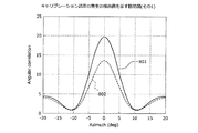
図8は、キャリブレーション誤差の発生の検出例を示す説明図(その1)である。図8の説明図は、上記(20)式を用いた場合のキャリブレーション誤差の発生の検出例を示している。図8において、横軸は角度を示し、縦軸は角度相関を示している。図8のグラフ801で横軸の位置がθmに対応する角度相関値は、エラーフリー時における真の角度θmに対応する評価関数の値f(I,θm)を示している。
(Example of detection of occurrence of calibration error)
FIG. 8 is an explanatory diagram (part 1) illustrating a detection example of occurrence of a calibration error. The explanatory diagram of FIG. 8 shows a detection example of the occurrence of a calibration error in the case where the above equation (20) is used. In FIG. 8, the horizontal axis indicates the angle, and the vertical axis indicates the angle correlation. Angle correlation values the position of the horizontal axis corresponds to theta m graphically 801 of FIG. 8 shows the value f of the evaluation function corresponding to the true angle θ m (I, θ m) at the time of error-free.
一方、グラフ802は、キャリブレーション誤差が生じている場合における角度相関を示している。真の角度θmに対し、キャリブレーション誤差Cが発生した後で推定された到来角度θkにおける評価関数の値f(C,θk)は、参照値に比べて低い値を示している。グラフ802は、キャリブレーション誤差の正/負に応じて、グラフ801の上/下にレベルがシフトする。角度推定装置100は、グラフ801,802との相違が閾値を超えた場合にキャリブレーション誤差が発生したものと判定する。
On the other hand, a graph 802 shows the angle correlation when a calibration error occurs. For the true angle θ m , the evaluation function value f (C, θ k ) at the arrival angle θ k estimated after the occurrence of the calibration error C is lower than the reference value. In the graph 802, the level shifts up / down of the
このように、角度推定装置100は、運用中に得た受信信号から、角度θに対する値がキャリブレーション誤差Cだけに反応して変化する評価関数f(C,θ)によって得られる算出値f(C,θk)と、エラーフリー時の参照値f(I,θm)とを比較する。このため、角度推定装置100の運用中にキャリブレーション誤差の発生を自律して検出することができる。具体的には、受信信号の実際の到来角度が既知でない状態であっても、キャリブレーション誤差の発生を検出することができる。
In this manner, the
また、キャリブレーション誤差が発生した場合に警告を発してもよい。これにより、ユーザにキャリブレーション誤差の補正(修理)を促すことができる。また、キャリブレーション誤差が発生した場合、例えば、上述または後述の手段を用いて補正処理を行ってもよい。これにより、角度推定装置100による到来角度の推定精度が低下することを抑えることができる。
A warning may be issued when a calibration error occurs. This can prompt the user to correct (repair) the calibration error. Further, when a calibration error occurs, for example, correction processing may be performed using the above-described or later-described means. Thereby, it can suppress that the estimation precision of the angle of arrival by the
(実施の形態2)
次に、角度推定装置100の実施の形態2について説明する。実施の形態1では、ESPRIT法によるキャリブレーション誤差の推定について説明したが、実施の形態2ではスペクトラム走査型の手法によるキャリブレーション誤差の推定について説明する。実施の形態2においては、実施の形態1と異なる部分について説明を行う。
(Embodiment 2)
Next, a second embodiment of the
(スペクトラム走査型の手法による評価関数について)
Capon法、MUSIC法、プリズム法およびLP法といったスペクトラム走査型の手法(ESPRIT型以外の手法)における評価関数は、以下のように導出することができる。例えば、キャリブレーション誤差が生じた場合は、上記(10)式はキャリブレーション誤差を含んだ異なる式となる。
(Evaluation function by spectrum scanning method)
An evaluation function in a spectrum scanning type method (a method other than the ESPRIT type) such as the Capon method, the MUSIC method, the prism method, and the LP method can be derived as follows. For example, when a calibration error occurs, the above equation (10) is a different equation including the calibration error.
ここで、キャリブレーション誤差が存在しないとき、図1に示した保存部103は、検出部104によって推定された各信号の入射角度θm(m=1〜M)と合わせて、角度毎にモードベクトルの測定値b0(θm)を保存しておく。さらに、モードベクトルは個々のアンテナ素子の角度θに対する特性を用いて、下記(23)式のようにモデル化できるので、先のデータb0(θm)を用いてモードベクトルのモデルb(θ)を生成し、同様に保存部103に保存しておく。gは、受信回路101(より具体的には、図2の受信アンテナ205a〜dからA/D変換器208までのアナログ回路)の総合特性である。
Here, when there is no calibration error, the
また、検出部104は、動作中に推定部102によって推定された入射角度が、保存部103に保存された各信号の入射角度の近傍(近傍の定義は上述)の角度であった場合、該推定角度を上述のモードベクトルモデルに代入する。そして、検出部104は、角度行列W=[b(θ1),…,b(θk)]を生成し、これとエラーフリー時に得たモードベクトルモデルb0(θ)とを用いて、下記(24)式で定義される評価関数の値を算出する。勿論、下記(24)式のθは変数である。
Further, the
上記(24)式に示す評価関数f(C,θ)を用いて、θm近傍の到来角度θkの検出時に算出値f(C,θk)を算出することができる。この算出値f(C,θk)の算出値と、参照値f(I,θm)とを比較して、相違が予め定めた閾値を超えた場合にキャリブレーション誤差が発生したものと判定することができる。なお、参照値f(I,θm)は、算出値f(C,θk)と同様に、スペクトラム走査型の手法によって算出された値である。 Using the evaluation function f (C, θ) shown in the above equation (24), the calculated value f (C, θ k ) can be calculated when the arrival angle θ k near θ m is detected. The calculated value f (C, θ k ) is compared with the reference value f (I, θ m ), and it is determined that a calibration error has occurred when the difference exceeds a predetermined threshold value. can do. Note that the reference value f (I, θ m ) is a value calculated by a spectrum scanning method, similarly to the calculated value f (C, θ k ).
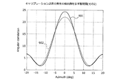
(キャリブレーション誤差の発生の検出例)
図9は、キャリブレーション誤差の発生の検出例を示す説明図(その2)である。図9の説明図は、上記(24)式を用いた場合のキャリブレーション誤差の検出例を示している。図9において、横軸は角度を示し、縦軸は角度相関を示している。図9のグラフ901は、エラーフリー時(参照値)を示している。一方、グラフ902は、キャリブレーション誤差が生じている場合を示している。グラフ902は、キャリブレーション誤差の正/負に応じて、グラフ901の上/下にレベルがシフトする。角度θmの近傍の角度θkにおけるグラフ901,902との相違が閾値を超えた場合にキャリブレーション誤差が発生したものと判定される。
(Example of detection of occurrence of calibration error)
FIG. 9 is an explanatory diagram (part 2) of a detection example of occurrence of a calibration error. The explanatory diagram of FIG. 9 shows an example of calibration error detection when the above equation (24) is used. In FIG. 9, the horizontal axis indicates the angle, and the vertical axis indicates the angle correlation. A
このように、スペクトラム走査型の手法によっても、評価関数f(C,θ)によって得られる算出値f(C,θk)と、エラーフリー時の参照値f(I,θm)とを比較することにより、キャリブレーション誤差の発生を検出することができる。このように、実施の形態2についても実施の形態1と同様の効果を得ることができる。 As described above, the calculated value f (C, θ k ) obtained by the evaluation function f (C, θ) is also compared with the reference value f (I, θ m ) at the time of error free even by the spectrum scanning method. By doing so, it is possible to detect the occurrence of a calibration error. As described above, the same effects as in the first embodiment can be obtained in the second embodiment.
(実施の形態3)
次に、角度推定装置100の実施の形態3について説明する。実施の形態3では位相誤差を考慮したキャリブレーション誤差の検出について説明する。実施の形態3においては、実施の形態1,2と異なる部分について説明を行う。
(Embodiment 3)
Next, a third embodiment of the
まず、図1に示した検出部104は、各受信アンテナ205からの出力信号のうち、互いに異なるアンテナ由来の2つの信号の組み合わせを取り出す。そして、検出部104は、組み合わせ毎に、組み合わせを構成する受信部105(受信アンテナ205)の間隔と、組み合わせから得られる2つの信号を用いて推定部102で算出される推定結果とに基づいて、2つの信号間の空間位相を算出する。また、検出部104は、組み合わせ毎に算出した空間位相の相違(空間位相差)に基づいて受信回路101の特性に対する重みの誤差の発生を検出する。
First, the
具体的には、N本の受信アンテナ205による着信信号から1組(互いに異なる2本)ずつの信号を取り出して、NC2組のモノパルスレーダとして各モノパルスレーダに着信した信号間の空間位相を計算する。そして、各組の位相のズレから誤差行列(上記(13)式参照)の位相成分を推定することができる。具体的には、p番目とq番目のアンテナ(アンテナ間隔をdpqとし、αpq=dpq/λ)を有するモノパルスレーダから得られる目標の角度をχpqとし(言うまでも無いが、目標が複数ある場合、χpqは各目標の角度をベクトル的に合成した値となる)、(p、q)の組み合わせ方を適当な番号r=1…NC2で区別すれば、位相の相違zrについて下記(25)式を得る。 Specifically, one set (two different from each other) of signals are extracted from the incoming signals from the N receiving antennas 205, and the spatial phase between the signals arriving at each monopulse radar as N C 2 sets of monopulse radar is calculated. calculate. Then, the phase component of the error matrix (see the above equation (13)) can be estimated from the phase shift of each set. Specifically, the target angle obtained from a monopulse radar having the p-th and q-th antennas (antenna spacing is d pq and α pq = d pq / λ) is χ pq (not to mention the target Χ pq is a value obtained by vector-combining the angles of each target), and the combination of (p, q) is distinguished by an appropriate number r = 1... NC 2. The following equation (25) is obtained for z r .
αrはdrによって定まる定数であるから、位相に関して、下記(26)式を得る。 alpha r is because a constant determined by d r, with respect to phase, to obtain the following equation (26).
上記(26)式は、NC2組分、得られる。キャリブレーション誤差がなければ、各χrは同じ値をとるはずである。そのため、各χrがばらついているのであれば、位相誤差(キャリブレーション誤差)が発生しているものと推定できる。そこで、例えばパラメータベクトルφを導入して、評価関数ε(C;φ)を下記(27)式によって定義し、同式が最小となるφの値を最小二乗問題として求めれば、その解が位相誤差の推定値となる。下記(27)式では、展開の一例も示す。 The above equation (26) is obtained for two N C pairs. If there is no calibration error, each χ r should take the same value. Therefore, if each χ r varies, it can be estimated that a phase error (calibration error) has occurred. Therefore, for example, if the parameter vector φ is introduced and the evaluation function ε (C; φ) is defined by the following equation (27), and the value of φ that minimizes the equation is obtained as the least square problem, the solution is the phase. This is an estimate of the error. The following formula (27) also shows an example of development.
上記(27)式により、キャリブレーション誤差における位相誤差を検出することができる。実施の形態3によれば、角度推定装置100の運用中にキャリブレーション誤差(位相誤差)を自律して検出することができる。具体的には、受信信号の実際の到来角度が既知でない状態であっても、上述の如き操作で位相誤差を検出することができる。
The phase error in the calibration error can be detected by the above equation (27). According to the third embodiment, the calibration error (phase error) can be detected autonomously during operation of the
(実施の形態4)
次に、角度推定装置100の実施の形態4について説明する。実施の形態4では、雑音固有ベクトルEnを用いたキャリブレーション誤差の検出について説明する。実施の形態4においては、実施の形態1〜3と異なる部分について説明を行う。
(Embodiment 4)
Next, a fourth embodiment of the
図1に示した検出部104は、推定部102によって推定された各信号の入射角度が所定の入射角度(例えばθk)である場合、保存部103によって保存されたモードベクトルの測定値に基づいて、評価関数による評価値を算出する。評価関数は、キャリブレーション誤差および各信号の入射角度に応じて変化する評価値を算出可能な関数である。
1 is based on the measured value of the mode vector stored by the
評価関数は、重みの誤差がない状態で複数の入射角度θm(m=1〜M)についてMUSIC法を適用して得られる雑音固有ベクトルから成る行列En(煩雑なので、以下雑音固有ベクトルと記す)と行列W(例えば上記(20)式参照)とによって表される。 The evaluation function is a matrix E n composed of noise eigenvectors obtained by applying the MUSIC method with respect to a plurality of incident angles θ m (m = 1 to M) in a state where there is no weight error (because it is complicated, hereinafter referred to as a noise eigenvector) And a matrix W (for example, see the above equation (20)).
行列Wは、例えば、保存部103によって保存されたモードベクトルの測定値と、キャリブレーション誤差および各信号の入射角度に応じて変化する評価値を算出可能な関数と、に基づく行列である。行列Wは、例えば、下記(28)式によって表すことができる。Vは、推定部102における角度推定の際に用いる所定の行列(例えばU1 -1U2(上記(18)式参照))を固有値分解した固有ベクトルから得られる行列である。また、Ωは、所定の行列(例えばU1 -1U2)の固有値である。
The matrix W is, for example, a matrix based on the measured value of the mode vector stored by the
また、例えば、Lは、J1およびJ2と同様に行列から特定の要素を取り出すベクトルである(上記(16)式参照)。Lを表す01×2は1行2列の行ベクトルを示し、1はスカラーを示す(なお、Lの列数はV-Hの行数と等しく定め、どれか一つの列の値のみを1とする。この例は最終要素を1としたものを示す)。また、例えば、m行n列の行ベクトルを示す0m×nによりLを表すことも可能である。この場合、どれか一つの列の値のみを1とすることも可能であるし、どれか一つの列の値のみを1以外の他の値とすることも可能である。 Further, for example, L is a vector for extracting a specific element from the matrix in the same manner as J 1 and J 2 (see the above equation (16)). 0 1 × 2 representing L represents a row vector of 1 row and 2 columns, and 1 represents a scalar (note that the number of columns of L is set equal to the number of rows of V H , and only the value of any one column is determined. 1. This example shows the final element as 1.) Further, for example, L can be represented by 0 m × n indicating a row vector of m rows and n columns. In this case, only one column value can be set to 1, and only one column value can be set to a value other than 1.
例えば、行列Wは、複数の受信部105間における各信号の空間位相差に基づいて各信号の入射角度を推定する際に用いる所定の行列U1 -1U2(上記(18)式参照)を固有値分解した時に得られる複数の行列の組み合わせV,Ωに基づく行列とすることができる。また、行列Wは、上述した実施の形態2における上記(23)式および上記(24)式で定義される角度行列とすることもできる。 For example, the matrix W is a predetermined matrix U 1 −1 U 2 used when estimating the incident angle of each signal based on the spatial phase difference of each signal between the plurality of receiving units 105 (see the above equation (18)). Can be a matrix based on a combination V, Ω of a plurality of matrices obtained when eigenvalue decomposition is performed. The matrix W can also be an angle matrix defined by the above formula (23) and the above formula (24) in the second embodiment.
本実施形態における評価関数は、f(C,θ)=EnWHなる式によって定義される。検出部104は、この評価関数と、雑音固有ベクトルEnと、行列Wと、に基づいて、キャリブレーションの誤差の発生を検出する。
Evaluation function in this embodiment, f (C, θ) = is defined by E n W H becomes equation.
検出部104は、予め保存部103に記憶されている雑音固有ベクトルEnを、推定部102によって推定された各信号の入射角度が、所定の入射角度である場合に保存部103から取得してもよい。また、検出部104は、推定部102によって推定された各信号の入射角度が所定の入射角度である場合に、雑音固有ベクトルEnを算出してもよい。
具体的には、実施の形態4では、行列W(=A0)と、キャリブレーション後に複数の角度m(m=1〜M)についてMUSIC法を用いて雑音固有ベクトルEnを求め、これらを保存しておく。雑音固有ベクトルEnは、キャリブレーション誤差がない状態において算出される値である。また、雑音固有ベクトルEnは、例えば、「受信アンテナ205の数」から「信号数」を減算した値が1以上のときに限って算出可能な値である。信号数とは、目標物の数である。例えば、雑音固有ベクトルEnは、受信アンテナ205が4本であれば、目標の数が3つ以下の場合に算出可能なベクトルである。 Specifically, in the fourth embodiment, the matrix W (= A 0), obtains the noise eigenvectors E n using the MUSIC method for calibration after multiple angles m (m = 1~M), stores these Keep it. Noise eigenvectors E n is a value calculated in the absence calibration error. Also, the noise eigenvectors E n, for example, a value obtained by subtracting "the number of signals" from the "number of receive antennas 205" is capable of calculating values only when one or more. The number of signals is the number of targets. For example, the noise eigenvectors E n, if the receiving antenna 205 is four, the number of the target is a vector can be calculated if three or less.
雑音固有ベクトルEnは、MUSIC法を用いて算出した雑音固有ベクトルである。MUSIC法は、信号の共分散行列に固有値分解を適用して、該行列を、信号固有空間を張るベクトルと雑音固有空間を張るベクトルとで表記し、信号部分空間と雑音部分空間との直交性を利用して目標の角度推定を行う手法である。 Noise eigenvectors E n is the noise eigenvectors calculated using the MUSIC method. The MUSIC method applies eigenvalue decomposition to a covariance matrix of a signal, expresses the matrix as a vector extending a signal eigenspace and a vector extending a noise eigenspace, and orthogonality between the signal subspace and the noise subspace. This is a method for estimating the target angle using the.
また、下記(29)式には信号共分散行列Rvvに固有値分解をして得られる関係式を示す。Esは信号部分空間を張る固有ベクトルを要素とする行列であり、Enは雑音固有空間を張るベクトルを要素とする行列であり、Λsは信号部分空間の固有値であり、σ2は雑音電力である。なお、下記(29)式において、vは着信信号を示し、sはシグナルを示し、nはノイズを示す。 The following equation (29) shows a relational expression obtained by performing eigenvalue decomposition on the signal covariance matrix R vv . E s is a matrix whose elements are eigenvectors extending the signal subspace, E n is a matrix whose elements are vectors extending the noise eigenspace, Λ s is an eigenvalue of the signal subspace, and σ 2 is the noise power It is. In the following equation (29), v represents an incoming signal, s represents a signal, and n represents noise.
![]()
![]()
ここで、周知の如く、信号部分空間を張るベクトルからなる行列Esは信号の角度行列と並行、すなわち、Es‖A0であり、一方、Es⊥Enであるから、En⊥A0であり、したがってキャリブレーション誤差がない場合には、EsEn=0となる。そのため、キャリブレーション誤差がない場合は、f(I,θ)=EnWH=EnA0 H=0となる。一方、キャリブレーション誤差が生じている場合は、f(C,θ)=EnWH=EnCAH≠0となる。このように、f(C,θ)が0であるか否かにより、キャリブレーション誤差を検出することができる。 Here, as is well known, the matrix E s consisting of a vector signal subspace spanned is parallel with the signal of the angle matrix, i.e., an E s ‖A 0, whereas, because it is E s ⊥E n, E n ⊥ If A 0 and thus there is no calibration error, then E s E n = 0. Therefore, when there is no calibration error, f (I, θ) = E n W H = E n A 0 H = 0. On the other hand, when a calibration error has occurred, f (C, θ) = E n W H = E n CA H ≠ 0. Thus, a calibration error can be detected by determining whether f (C, θ) is 0 or not.
実施の形態4によれば、角度推定装置100の運用中にキャリブレーション誤差の発生を自律して検出することができる。具体的には、受信信号の実際の到来角度が既知でない状態であっても、キャリブレーション誤差の発生を検出することができる。
According to the fourth embodiment, it is possible to autonomously detect the occurrence of a calibration error during operation of the
上述した実施の形態1〜4に関し、さらに以下の付記を開示する。 The following additional notes are disclosed with respect to the above-described first to fourth embodiments.
(付記1)複数の受信部を含み、キャリブレーションによって設定された重みを用いて前記複数の受信部に入射された各信号を重み付けする受信回路(信号処理部を含む)と、
前記受信回路によって重み付けされた各信号に基づいて前記各信号の入射角度を推定する推定部と、
前記受信回路の特性に対する前記重みの誤差がない状態における前記受信回路の特性を反映したモードベクトルの測定値を保存し、前記誤差がない状態における、前記誤差および前記各信号の入射角度に応じて変化する評価値を算出可能な評価関数による前記評価値の算出結果と前記推定部による前記各信号の入射角度とを対応付けて保存する保存部と、
前記推定部によって推定された前記各信号の入射角度が、前記保存部によって保存された前記各信号の入射角度近傍の値に対応する角度である場合、前記保存部によって保存されたモードベクトルの測定値と前記評価関数とに基づく評価値を算出し、算出した評価値と前記保存部によって保存された評価値との比較に基づいて前記誤差の発生を検出する検出部と、
を有することを特徴とする角度推定装置。
(Supplementary Note 1) A receiving circuit (including a signal processing unit) that includes a plurality of receiving units and weights each signal incident on the plurality of receiving units using a weight set by calibration;
An estimation unit that estimates an incident angle of each signal based on each signal weighted by the receiving circuit;
The measured value of the mode vector reflecting the characteristics of the receiving circuit in a state where there is no error in the weight with respect to the characteristics of the receiving circuit is stored, and in accordance with the error and the incident angle of each signal in the state without the error A storage unit for storing the calculation result of the evaluation value by an evaluation function capable of calculating a changing evaluation value and the incident angle of each signal by the estimation unit in association with each other;
When the incident angle of each signal estimated by the estimation unit is an angle corresponding to a value near the incident angle of each signal stored by the storage unit, the mode vector stored by the storage unit is measured. A detection unit that calculates an evaluation value based on the value and the evaluation function, and detects the occurrence of the error based on a comparison between the calculated evaluation value and the evaluation value stored by the storage unit;
An angle estimation device comprising:
(付記2)前記推定部は、前記複数の受信部間における前記各信号の空間位相差を用いて前記各信号の入射角度を推定し、
前記評価関数は、前記推定部における角度推定の際に用いる所定の行列を固有値分解して得られる複数の行列を組み合わせることによって生成される行列Wを用いて定義される関数(下記(30)式)であることを特徴とする付記1に記載の角度推定装置。
![]()
The evaluation function is a function defined using a matrix W generated by combining a plurality of matrices obtained by eigenvalue decomposition of a predetermined matrix used for angle estimation in the estimation unit (formula (30) below) The angle estimation apparatus according to Supplementary Note 1, wherein
![]()
(付記3)前記検出部は、前記(30)式のWWHの対角要素から得られる前記誤差に関する値に基づいて前記複数の受信部のうちの前記誤差の発生した受信部を検出することを特徴とする付記2に記載の角度推定装置。 (Supplementary Note 3) The detection unit is to detect the receiver generated the error of said (30) said plurality of receiving unit based on the value relating to the error obtained from the diagonal elements of WW H of Formula The angle estimation apparatus according to appendix 2, characterized by:
(付記4)前記検出部は、前記誤差に関する値に基づいて前記誤差の振幅成分を検出することを特徴とする付記3に記載の角度推定装置。
(Additional remark 4) The said estimation part detects the amplitude component of the said error based on the value regarding the said error, The angle estimation apparatus of
(付記5)前記検出部は、前記(30)式の前記行列Wと、角度行列A0=[a0(θ1),…,a0(θk)]の一般逆行列と、に基づいて前記誤差の値を検出することを特徴とする付記2〜4のいずれか一つに記載の角度推定装置。 (Supplementary Note 5) The detection unit includes: the matrix W of the equation (30), the angle matrix A 0 = [a 0 (θ 1), ..., a 0 (θ k)] based and generalized inverse matrix, the The angle estimation device according to any one of appendices 2 to 4, wherein the error value is detected.
(付記6)前記受信回路は、前記複数の受信部によって受信された各信号を増幅するアンプ、アンプからの出力信号を復調するミキサ、ミキサからの出力をデジタル信号に変換するA/D(Analog to Digital)変換器、および信号処理部を含み、
前記推定部は、前記受信回路によって重み付けされた各信号の角度スペクトラムの走査に基づいて前記各信号の入射角度を推定し、
前記保存部は、前記推定部によって推定された前記各信号の入射角度θm(m=1〜M)に基づく前記モードベクトルの測定値b0(θm)とともに、このデータを用いてモードベクトルモデルb(θm)(角度は変数扱い)を生成、保存しておき(下記(31)式)、
前記検出部は、前記推定部によって推定された入射角度が、前記保存部によって保存された前記各信号の入射角度θmの近傍の角度であった場合、θmに代えて該推定角度θkを前記モードベクトルモデルb(θm)に代入し、角度行列W=[b(θ1),…,b(θk)]を生成し、前記評価関数(下記(32)式)に基づいて評価値を算出することを特徴とする付記1に記載の角度推定装置。
![]()
![]()
The estimating unit estimates an incident angle of each signal based on scanning of an angle spectrum of each signal weighted by the receiving circuit;
The storage unit uses this data along with the measured value b 0 (θ m ) of the mode vector based on the incident angle θ m (m = 1 to M) of each signal estimated by the estimation unit, and uses this data to generate a mode vector. A model b (θ m ) (the angle is treated as a variable) is generated and stored (the following equation (31))
When the incident angle estimated by the estimating unit is an angle near the incident angle θ m of each signal stored by the storing unit, the detecting unit replaces the estimated angle θ k with θ m. Is substituted into the mode vector model b (θ m ) to generate an angle matrix W = [b (θ 1 ),..., B (θ k )], and based on the evaluation function (Equation (32) below) The angle estimation apparatus according to appendix 1, wherein an evaluation value is calculated.
![]()
![]()
(付記7)複数の受信部を含み、キャリブレーションによって設定された重みを用いて前記複数の受信部に入射された各信号を重み付けする受信回路(信号処理部を含む)と、
前記受信回路によって重み付けされた各信号に基づいて前記各信号の入射角度を推定する推定部と、
互いに異なる2つの受信部からの信号の組み合わせ毎に、前記組み合わせを構成する受信部の間隔と、前記組み合わせから得られる2つの信号を用いて算出される前記推定部による推定結果と、に基づいて前記組み合わせの空間位相を算出し、前記組み合わせ毎に算出した空間位相の相違に基づいて前記受信回路の特性に対する前記重みの誤差の発生を検出する検出部と、
を有することを特徴とする角度推定装置。
(Supplementary Note 7) A receiving circuit (including a signal processing unit) that includes a plurality of receiving units and weights each signal incident on the plurality of receiving units using a weight set by calibration;
An estimation unit that estimates an incident angle of each signal based on each signal weighted by the receiving circuit;
For each combination of signals from two different reception units, based on the interval between the reception units constituting the combination and the estimation result by the estimation unit calculated using two signals obtained from the combination A detection unit that calculates a spatial phase of the combination and detects the occurrence of an error in the weight with respect to the characteristics of the reception circuit based on a difference in the spatial phase calculated for each combination;
An angle estimation device comprising:
(付記8)複数の受信部を含み、キャリブレーションによって設定された重みを用いて前記複数の受信部に入射された各信号を重み付けする受信回路(信号処理部を含む)と、
前記受信回路によって重み付けされた各信号に基づいて前記各信号の入射角度を推定する推定部と、
前記受信回路の特性に対する前記重みの誤差がない状態における前記受信回路の特性を反映したモードベクトルの測定値を保存する保存部と、
前記推定部によって推定された前記各信号の入射角度が所定の入射角度である場合、前記保存部によって保存されたモードベクトルの測定値と、前記誤差および前記各信号の入射角度に応じて変化する評価値を算出可能な関数と、に基づく行列W(下記(33)式)を算出し、算出した前記行列Wと、前記重みの誤差がない状態における複数の入射角度θm(m=1〜M)についてMUSIC(MUltiple SIgnal Classification)法により得られる雑音固有ベクトルEnと、所定の関数(下記(34)式)と、に基づいて前記誤差の発生を検出する検出部と、
を有することを特徴とする角度推定装置。
![]()
An estimation unit that estimates an incident angle of each signal based on each signal weighted by the receiving circuit;
A storage unit for storing a measured value of a mode vector reflecting the characteristics of the receiving circuit in a state where there is no error in the weight with respect to the characteristics of the receiving circuit;
When the incident angle of each signal estimated by the estimation unit is a predetermined incident angle, it changes according to the measured value of the mode vector stored by the storage unit, the error, and the incident angle of each signal. A matrix W (Equation (33) below) based on a function that can calculate an evaluation value is calculated, and the calculated matrix W and a plurality of incident angles θ m (m = 1 to 2) in a state in which there is no weight error. (a noise eigenvectors E n obtained by MUltiple SIgnal Classification) method, a predetermined function (below (34) for MUSIC M) and formula), a detector for detecting the occurrence of the error based on,
An angle estimation device comprising:
![]()
(付記9)複数の受信部を含み、キャリブレーションによって設定された重みを用いて前記複数の受信部に入射された各信号を重み付けする受信回路によって重み付けされた各信号に基づいて前記各信号の入射角度を推定し、
前記受信回路の特性に対する前記重みの誤差がない状態における前記受信回路の特性を反映したモードベクトルの測定値を保存し、前記誤差がない状態における、前記誤差および前記各信号の入射角度に応じて変化する評価値を算出可能な評価関数による前記評価値の算出結果と、推定した前記各信号の入射角度とを対応付けて保存し、
推定した前記各信号の入射角度が、保存した前記各信号の入射角度近傍の値に対応する角度である場合、保存したモードベクトルの測定値と前記評価関数とに基づく評価値を算出し、算出した評価値と保存した評価値との比較に基づいて前記誤差の発生を検出する、
ことを特徴とする角度推定方法。
(Supplementary note 9) A plurality of receiving units are included, and each signal is weighted based on each signal weighted by a receiving circuit that weights each signal incident on the plurality of receiving units using a weight set by calibration. Estimate the incident angle,
The measured value of the mode vector reflecting the characteristics of the receiving circuit in a state where there is no error in the weight with respect to the characteristics of the receiving circuit is stored, and in accordance with the error and the incident angle of each signal in the state without the error A calculation result of the evaluation value by an evaluation function capable of calculating a changing evaluation value and an estimated incident angle of each signal are stored in association with each other,
When the estimated incident angle of each signal is an angle corresponding to a value near the stored incident angle of each signal, an evaluation value based on the measured value of the stored mode vector and the evaluation function is calculated and calculated. Detecting the occurrence of the error based on a comparison between the evaluated value and the stored evaluation value;
An angle estimation method characterized by the above.
(付記10)複数の受信部を含み、キャリブレーションによって設定された重みを用いて前記複数の受信部に入射された各信号を重み付けする受信回路によって重み付けされた各信号に基づいて前記各信号の入射角度を推定し、
互いに異なる2つの受信部からの信号の組み合わせ毎に、前記組み合わせを構成する受信部の間隔と、前記組み合わせから得られる2つの信号に基づいて算出される前記入射角度の推定結果から空間位相を算出し、前記組み合わせ毎に算出した空間位相の相違に基づいて前記受信回路の特性に対する前記重みの誤差の発生を検出する、
ことを特徴とする角度推定方法。
(Supplementary Note 10) A plurality of receiving units are included, and each signal is weighted based on each signal weighted by a receiving circuit that weights each signal incident on the plurality of receiving units using a weight set by calibration. Estimate the incident angle,
For each combination of signals from two different receiving units, the spatial phase is calculated from the interval between the receiving units constituting the combination and the incident angle estimation result calculated based on the two signals obtained from the combination. And detecting the occurrence of an error in the weight for the characteristics of the receiving circuit based on a difference in spatial phase calculated for each combination.
An angle estimation method characterized by the above.
(付記11)複数の受信部を含み、キャリブレーションによって設定された重みを用いて前記複数の受信部に入射された各信号を重み付けする受信回路によって重み付けされた各信号に基づいて前記各信号の入射角度を推定し、
前記受信回路の特性に対する前記重みの誤差がない状態における前記受信回路の特性を反映したモードベクトルの測定値を保存し、
推定した前記各信号の入射角度が所定の入射角度である場合、保存したモードベクトルの測定値と、前記誤差および前記各信号の入射角度に応じて変化する評価値を算出可能な関数と、に基づく行列W(下記(35)式)を算出し、算出した前記行列Wと、前記重みの誤差がない状態における複数の入射角度θm(m=1〜M)についてMUSIC(MUltiple SIgnal Classification)法により得られる雑音固有ベクトルEnと、所定の関数(下記(36)式)と、に基づいて前記誤差の発生を検出する、
ことを特徴とする角度推定方法。
![]()
Storing the measured value of the mode vector reflecting the characteristics of the receiving circuit in a state where there is no error in the weight with respect to the characteristics of the receiving circuit;
When the estimated incident angle of each signal is a predetermined incident angle, the measured value of the stored mode vector and a function that can calculate an evaluation value that changes according to the error and the incident angle of each signal, A matrix W (formula (35) below) is calculated, and a MUSIC (Multiple Signal Classification) method is used for the calculated matrix W and a plurality of incident angles θ m (m = 1 to M) in a state where there is no weight error. the noise eigenvectors E n obtained by a predetermined function (following equation (36)), to detect the occurrence of the error based on,
An angle estimation method characterized by the above.
![]()
100 角度推定装置
101 受信回路
102,221 推定部
103 保存部
104 検出部
105 受信部
201 発振回路
202 方向性結合器
203 パワーアンプ
204 送信アンテナ
205(205a〜205d) 受信アンテナ
206 ローノイズアンプ
207 ミキサ
208 A/D変換器
209 信号処理部
222 角度行列再生部
223 参照値テーブル
224 スペクトラム比較部
301 CPU
302 メモリ
303 インタフェース
DESCRIPTION OF
302
Claims (9)
前記受信回路によって重み付けされた各信号に基づいて前記各信号の入射角度を推定する推定部と、
前記受信回路の特性に対する前記重みの誤差がない状態における、前記誤差および前記各信号の入射角度に応じて変化する評価値を算出可能な評価関数による前記評価値の算出結果と前記推定部によって推定された前記各信号の入射角度とを対応付けて保存する保存部と、
前記推定部によって推定された前記各信号の入射角度が、前記保存部によって保存された前記各信号の入射角度近傍の値に対応する角度である場合、前記評価関数に基づく評価値を算出し、算出した評価値と前記保存部によって保存された評価値との比較に基づいて前記誤差の発生を検出する検出部と、
を有することを特徴とする角度推定装置。 A receiving circuit that includes a plurality of receiving units and weights each signal incident on the plurality of receiving units using a weight set by calibration;
An estimation unit that estimates an incident angle of each signal based on each signal weighted by the receiving circuit;
In the absence erroneous difference of the weight on the properties of the receiver circuit, the estimation unit calculating result of the evaluation value by the error and the calculated possible evaluation function evaluation value that varies depending on the incident angle of each signal a storage unit which stores in association with the incident angle of the estimated each signal I O,
The calculated incidence angle of each of the signal estimated by the estimation unit, when the stored by the storage unit is an angle corresponding to the value of the incident angle near each signal, the evaluation value based on the previous SL rating function number A detection unit that detects the occurrence of the error based on a comparison between the calculated evaluation value and the evaluation value stored by the storage unit;
An angle estimation device comprising:
前記推定部は、前記複数の受信部間における前記各信号に基づく所定の行列の固有値分解を含む処理により前記各信号の入射角度を推定し、
前記評価関数は、前記推定部における角度推定の際に用いる前記所定の行列を固有値分解して得られる行列および固有値を組み合わせることによって生成される行列Wを用いて定義される関数(下記(1)式)であることを特徴とする請求項1に記載の角度推定装置。
The estimating unit estimates an incident angle of each signal by a process including eigenvalue decomposition of a predetermined matrix based on each signal between the plurality of receiving units,
The evaluation function is a function (below, defined by using a matrix W that is generated by combining the matrix and the eigenvalues of the predetermined matrix that is obtained by eigenvalue decomposition to be used in the angle estimation in the estimator ( The angle estimation apparatus according to claim 1, wherein 1) formula).
(Analog to Digital)変換器、および信号処理部を含み、
前記推定部は、前記受信回路によって重み付けされた各信号の角度スペクトラムの走査に基づいて前記各信号の入射角度を推定し、
前記保存部は、前記推定部によって推定された前記各信号の入射角度θm(m=1〜M)に基づく前記モードベクトルの測定値b0(θm)とともに、前記モードベクトルの測定値b 0 (θ m )を用いてモードベクトルモデルb(θm)(角度は変数扱い)を生成、保存しておき(下記(2)式)、
前記検出部は、前記推定部によって推定された入射角度が、前記保存部によって保存された前記各信号の入射角度θmの近傍の角度であった場合、θmに代えて該推定角度θkを前記モードベクトルモデルb(θm)に代入し、角度行列W=[b(θ1),…,b(θk)]を生成し、前記評価関数(下記(3)式)に基づいて評価値を算出することを特徴とする請求項1に記載の角度推定装置。
An (Analog to Digital) converter, and a signal processing unit;
The estimating unit estimates an incident angle of each signal based on scanning of an angle spectrum of each signal weighted by the receiving circuit;
The storage unit includes the mode vector measurement value b 0 (θ m ) based on the incident angle θ m (m = 1 to M) of each signal estimated by the estimation unit, and the mode vector measurement value b. A mode vector model b (θ m ) (angle is treated as a variable) is generated and stored using 0 (θ m ) (the following equation (2)),
When the incident angle estimated by the estimating unit is an angle near the incident angle θ m of each signal stored by the storing unit, the detecting unit replaces the estimated angle θ k with θ m. Is substituted into the mode vector model b (θ m ) to generate an angle matrix W = [b (θ 1 ),..., B (θ k )], and based on the evaluation function (the following equation (3)) The angle estimation apparatus according to claim 1, wherein an evaluation value is calculated.
前記受信回路によって重み付けされた各信号に基づいて前記各信号の入射角度を推定する推定部と、
互いに異なる2つの受信部からの信号の組み合わせ毎に、前記組み合わせを構成する受信部の間隔と、前記組み合わせから得られる2つの信号を用いて算出される前記推定部による推定結果と、に基づいて前記組み合わせの空間位相を算出し、前記組み合わせ毎に算出した空間位相の相違に基づいて前記受信回路の特性に対する前記重みの誤差の発生を検出する検出部と、
を有することを特徴とする角度推定装置。 A receiving circuit that includes a plurality of receiving units and weights each signal incident on the plurality of receiving units using a weight set by calibration;
An estimation unit that estimates an incident angle of each signal based on each signal weighted by the receiving circuit;
For each combination of signals from two different reception units, based on the interval between the reception units constituting the combination and the estimation result by the estimation unit calculated using two signals obtained from the combination A detection unit that calculates a spatial phase of the combination and detects the occurrence of an error in the weight with respect to the characteristics of the reception circuit based on a difference in the spatial phase calculated for each combination;
An angle estimation device comprising:
前記受信回路によって重み付けされた各信号に基づく所定の行列の固有値分解を含む処理により前記各信号の入射角度を推定する推定部と、
前記受信回路の特性に対する前記重みの誤差がない状態における前記受信回路の特性を反映したモードベクトルの測定値を保存する保存部と、
前記推定部によって推定された前記各信号の入射角度が所定の入射角度である場合、前記保存部によって保存されたモードベクトルの測定値と、前記誤差および前記各信号の入射角度に応じて変化する評価値を算出可能な関数と、に基づく行列W(下記(4)式)を算出し(ただし、Lの列数はV-Hの行数と等しく定める)、算出した前記行列Wと、前記重みの誤差がない状態における複数の入射角度θm(m=1〜M)についてMUSIC(MUltiple SIgnal Classification)法により得られる雑音固有ベクトルEnと、所定の関数(下記(5)式)と、に基づいて前記誤差の発生を検出する検出部と、
を有することを特徴とする角度推定装置。
An estimation unit for estimating an incident angle of each of the signal by processing including eigenvalue decomposition of based rather prescribed matrix to each signal weighted by the reception circuit,
A storage unit for storing a measured value of a mode vector reflecting the characteristics of the receiving circuit in a state where there is no error in the weight with respect to the characteristics of the receiving circuit;
When the incident angle of each signal estimated by the estimation unit is a predetermined incident angle, it changes according to the measured value of the mode vector stored by the storage unit, the error, and the incident angle of each signal. A function capable of calculating an evaluation value, and a matrix W (Equation (4) below) is calculated (provided that the number of columns of L is equal to the number of rows of V −H ), and the calculated matrix W, the noise eigenvectors E n obtained by MUSIC (mUltiple SIgnal Classification) method for a plurality of incident angle theta m (m = 1 to m) in the absence error weights, and a predetermined function (equation (5) below), the A detection unit for detecting the occurrence of the error based on;
An angle estimation device comprising:
前記受信回路の特性に対する前記重みの誤差がない状態における、前記誤差および前記各信号の入射角度に応じて変化する評価値を算出可能な評価関数による前記評価値の算出結果と、推定した前記各信号の入射角度とを対応付けて保存し、
推定した前記各信号の入射角度が、保存した前記各信号の入射角度近傍の値に対応する角度である場合、前記評価関数に基づく評価値を算出し、算出した評価値と保存した評価値との比較に基づいて前記誤差の発生を検出する、
ことを特徴とする角度推定方法。 Estimating the incident angle of each signal based on each signal weighted by a receiving circuit including a plurality of receiving units and weighting each signal incident on the plurality of receiving units using a weight set by calibration And
In error such have state of the weight on the properties of the receiver circuit, a calculation result of the evaluation value by the error and the calculated possible evaluation function evaluation value that varies depending on the incident angle of each signal was estimated Corresponding and storing the incident angle of each signal,
The incident angle of the estimated said each signal, when the stored is an angle corresponding to the value of the incident angle near each signal, calculates an evaluation value based on the previous SL evaluation function number, and stored with the calculated evaluation value evaluation Detecting the occurrence of the error based on a comparison with a value;
An angle estimation method characterized by the above.
互いに異なる2つの受信部からの信号の組み合わせ毎に、前記組み合わせを構成する受信部の間隔と、前記組み合わせから得られる2つの信号に基づいて算出される前記入射角度の推定結果から空間位相を算出し、前記組み合わせ毎に算出した空間位相の相違に基づいて前記受信回路の特性に対する前記重みの誤差の発生を検出する、
ことを特徴とする角度推定方法。 Estimating the incident angle of each signal based on each signal weighted by a receiving circuit including a plurality of receiving units and weighting each signal incident on the plurality of receiving units using a weight set by calibration And
For each combination of signals from two different receiving units, the spatial phase is calculated from the interval between the receiving units constituting the combination and the incident angle estimation result calculated based on the two signals obtained from the combination. And detecting the occurrence of an error in the weight for the characteristics of the receiving circuit based on a difference in spatial phase calculated for each combination.
An angle estimation method characterized by the above.
前記受信回路の特性に対する前記重みの誤差がない状態における前記受信回路の特性を反映したモードベクトルの測定値を保存し、
推定した前記各信号の入射角度が所定の入射角度である場合、保存したモードベクトルの測定値と、前記誤差および前記各信号の入射角度に応じて変化する評価値を算出可能な関数と、に基づく行列W(下記(6)式)を算出し(ただし、Lの列数はV-Hの行数と等しく定める)、算出した前記行列Wと、前記重みの誤差がない状態における複数の入射角度θm(m=1〜M)についてMUSIC(MUltiple SIgnal Classification)法により得られる雑音固有ベクトルEnと、所定の関数(下記(7)式)と、に基づいて前記誤差の発生を検出する、
ことを特徴とする角度推定方法。
Storing the measured value of the mode vector reflecting the characteristics of the receiving circuit in a state where there is no error in the weight with respect to the characteristics of the receiving circuit;
When the estimated incident angle of each signal is a predetermined incident angle, the measured value of the stored mode vector and a function that can calculate an evaluation value that changes according to the error and the incident angle of each signal, A matrix W based on the following equation (6) is calculated (where the number of columns of L is determined to be equal to the number of rows of V H ), and the calculated matrix W and a plurality of incidents in a state where there is no weight error the angle theta m (m = 1 to m) for MUSIC (MUltiple SIgnal Classification) noise eigenvectors obtained by method E n, and a predetermined function (following equation (7)), to detect the occurrence of the error based on,
An angle estimation method characterized by the above.
Priority Applications (3)
| Application Number | Priority Date | Filing Date | Title |
|---|---|---|---|
| JP2014208417A JP6362262B2 (en) | 2014-10-09 | 2014-10-09 | Angle estimation apparatus and angle estimation method |
| DE102015219483.3A DE102015219483B4 (en) | 2014-10-09 | 2015-10-08 | Angle estimation device and angle estimation method |
| US14/878,846 US10852410B2 (en) | 2014-10-09 | 2015-10-08 | Angle estimating apparatus and angle estimating method |
Applications Claiming Priority (1)
| Application Number | Priority Date | Filing Date | Title |
|---|---|---|---|
| JP2014208417A JP6362262B2 (en) | 2014-10-09 | 2014-10-09 | Angle estimation apparatus and angle estimation method |
Publications (2)
| Publication Number | Publication Date |
|---|---|
| JP2016080369A JP2016080369A (en) | 2016-05-16 |
| JP6362262B2 true JP6362262B2 (en) | 2018-07-25 |
Family
ID=55644355
Family Applications (1)
| Application Number | Title | Priority Date | Filing Date |
|---|---|---|---|
| JP2014208417A Active JP6362262B2 (en) | 2014-10-09 | 2014-10-09 | Angle estimation apparatus and angle estimation method |
Country Status (3)
| Country | Link |
|---|---|
| US (1) | US10852410B2 (en) |
| JP (1) | JP6362262B2 (en) |
| DE (1) | DE102015219483B4 (en) |
Families Citing this family (6)
| Publication number | Priority date | Publication date | Assignee | Title |
|---|---|---|---|---|
| US10469257B2 (en) * | 2015-01-15 | 2019-11-05 | Nippon Telegraph And Telephone Corporation | Matrix and key generation device, matrix and key generation system, matrix coupling device, matrix and key generation method, and program |
| US10481242B2 (en) * | 2015-09-25 | 2019-11-19 | Texas Instruments Incorporated | Method for joint antenna-array calibration and direction of arrival estimation for automotive applications |
| KR101796472B1 (en) | 2016-09-30 | 2017-12-12 | 숭실대학교 산학협력단 | Radar apparatus and DOA estimation method using the same |
| SG11202101826WA (en) * | 2018-08-23 | 2021-03-30 | Univ Texas | Controlling a device by tracking movement of hand using acoustic signals |
| JP7222952B2 (en) | 2020-07-29 | 2023-02-15 | 京セラ株式会社 | ELECTRONIC DEVICE, ELECTRONIC DEVICE CONTROL METHOD, AND PROGRAM |
| JP7472060B2 (en) | 2021-03-03 | 2024-04-22 | 株式会社日立国際電気 | Direction of Arrival Estimation System |
Family Cites Families (16)
| Publication number | Priority date | Publication date | Assignee | Title |
|---|---|---|---|---|
| DE19942665B4 (en) * | 1998-09-07 | 2014-02-13 | Denso Corporation | FM CW radar apparatus for measuring the distance to a target and the relative velocity of the target |
| JP4320441B2 (en) * | 2004-03-09 | 2009-08-26 | よこはまティーエルオー株式会社 | Array antenna calibration method and calibration apparatus |
| JP2006067869A (en) | 2004-09-01 | 2006-03-16 | Matsushita Electric Ind Co Ltd | Separating and recovering method |
| WO2006067857A1 (en) * | 2004-12-24 | 2006-06-29 | Fujitsu Limited | Arrival direction estimating device and program |
| US7199753B2 (en) * | 2005-06-16 | 2007-04-03 | Raytheon Company | Calibration method for receive only phased array radar antenna |
| JP4498269B2 (en) | 2005-11-30 | 2010-07-07 | 株式会社デンソーアイティーラボラトリ | Radar signal processing device |
| US7667646B2 (en) * | 2006-02-21 | 2010-02-23 | Nokia Corporation | System and methods for direction finding using a handheld device |
| US7873326B2 (en) * | 2006-07-11 | 2011-01-18 | Mojix, Inc. | RFID beam forming system |
| JP2010019086A (en) | 2008-07-08 | 2010-01-28 | Toyota Motor Corp | Internal combustion engine device, control method thereof, and vehicle |
| JP5192463B2 (en) | 2009-08-07 | 2013-05-08 | 株式会社デンソー | Signal processing device |
| JP5768953B2 (en) * | 2010-08-02 | 2015-08-26 | 日本電気株式会社 | Communication satellite, calibration system, and array antenna calibration method |
| JP5675285B2 (en) | 2010-11-10 | 2015-02-25 | 富士通テン株式会社 | Radar equipment |
| JP5701106B2 (en) | 2011-03-04 | 2015-04-15 | 富士通テン株式会社 | Radar device and method of calculating angle of arrival of radar device |
| JP5866917B2 (en) * | 2011-09-20 | 2016-02-24 | 富士通株式会社 | Detecting and ranging apparatus and detecting and ranging method |
| JP5865689B2 (en) * | 2011-12-08 | 2016-02-17 | 富士通株式会社 | Detecting and ranging apparatus and angle estimation method |
| JP2014115137A (en) * | 2012-12-07 | 2014-06-26 | Fujitsu Ten Ltd | Radar apparatus and signal processing method |
-
2014
- 2014-10-09 JP JP2014208417A patent/JP6362262B2/en active Active
-
2015
- 2015-10-08 DE DE102015219483.3A patent/DE102015219483B4/en active Active
- 2015-10-08 US US14/878,846 patent/US10852410B2/en active Active
Also Published As
| Publication number | Publication date |
|---|---|
| US20160103207A1 (en) | 2016-04-14 |
| DE102015219483B4 (en) | 2023-06-15 |
| US10852410B2 (en) | 2020-12-01 |
| DE102015219483A1 (en) | 2016-04-14 |
| JP2016080369A (en) | 2016-05-16 |
Similar Documents
| Publication | Publication Date | Title |
|---|---|---|
| JP6362262B2 (en) | Angle estimation apparatus and angle estimation method | |
| JP5659472B2 (en) | Direction of arrival estimation apparatus and method | |
| US11874395B2 (en) | Radar processing chain for frequency-modulated continuous wave radar systems | |
| US10379204B2 (en) | Method for calibrating a MIMO radar sensor for motor vehicles | |
| CN109407093B (en) | Doppler measurement for resolving ambiguity of angle of arrival of wide aperture radar | |
| US10389421B2 (en) | Apparatus for estimating arrival-angle and apparatus for beam-forming | |
| CN110018452B (en) | Method and apparatus for estimating direction of arrival using generation of virtual received signals | |
| US9470782B2 (en) | Method and apparatus for increasing angular resolution in an automotive radar system | |
| JP5617334B2 (en) | Radar apparatus and target detection method | |
| AU2014412888B2 (en) | Methods and systems for spectral analysis of sonar data | |
| EP3019888B1 (en) | Interference nulling of multipath signals in stacked beam pulse radar | |
| JP4794613B2 (en) | Signal wave arrival angle measurement device | |
| KR102422396B1 (en) | Method of spatial interpolation for linear phased array antenna and appratus thereof | |
| JP6395677B2 (en) | Direction of arrival estimation device | |
| KR101953697B1 (en) | Method and apparatus for estimating direction of arrival using generation of virtual received signals based on uniform linear array antenna | |
| CN107390197B (en) | Radar self-adaption sum-difference beam angle measurement method based on feature space | |
| US20070064537A1 (en) | Method for Improved Sonar Velocity Processing | |
| Lee et al. | Enhanced performance of MUSIC algorithm using spatial interpolation in automotive FMCW radar systems | |
| KR20190140362A (en) | Method and apparatus for estimating the number of signals in radar system | |
| GB2516064A (en) | Improvements in and relating to radar | |
| RU2581898C1 (en) | Method of measuring angular coordinates of target | |
| US11585892B1 (en) | Calibration for multi-channel imaging systems | |
| Robey et al. | Array calibration and modeling of steering vectors | |
| EP2824477A1 (en) | Interference nulling of multipath signals in stacked beam pulse radar | |
| Bruna et al. | Cramer-Rao Lower Bound assessment when using bistatic clutter mitigation techniques |
Legal Events
| Date | Code | Title | Description |
|---|---|---|---|
| A621 | Written request for application examination |
Free format text: JAPANESE INTERMEDIATE CODE: A621 Effective date: 20170629 |
|
| A131 | Notification of reasons for refusal |
Free format text: JAPANESE INTERMEDIATE CODE: A131 Effective date: 20180220 |
|
| A521 | Request for written amendment filed |
Free format text: JAPANESE INTERMEDIATE CODE: A523 Effective date: 20180423 |
|
| TRDD | Decision of grant or rejection written | ||
| A01 | Written decision to grant a patent or to grant a registration (utility model) |
Free format text: JAPANESE INTERMEDIATE CODE: A01 Effective date: 20180529 |
|
| A711 | Notification of change in applicant |
Free format text: JAPANESE INTERMEDIATE CODE: A711 Effective date: 20180613 |
|
| A521 | Request for written amendment filed |
Free format text: JAPANESE INTERMEDIATE CODE: A821 Effective date: 20180613 |
|
| A61 | First payment of annual fees (during grant procedure) |
Free format text: JAPANESE INTERMEDIATE CODE: A61 Effective date: 20180625 |
|
| R150 | Certificate of patent or registration of utility model |
Ref document number: 6362262 Country of ref document: JP Free format text: JAPANESE INTERMEDIATE CODE: R150 |
|
| R250 | Receipt of annual fees |
Free format text: JAPANESE INTERMEDIATE CODE: R250 |
|
| R250 | Receipt of annual fees |
Free format text: JAPANESE INTERMEDIATE CODE: R250 |
|
| R250 | Receipt of annual fees |
Free format text: JAPANESE INTERMEDIATE CODE: R250 |