JP5659472B2 - Direction of arrival estimation apparatus and method - Google Patents
Direction of arrival estimation apparatus and method Download PDFInfo
- Publication number
- JP5659472B2 JP5659472B2 JP2009201624A JP2009201624A JP5659472B2 JP 5659472 B2 JP5659472 B2 JP 5659472B2 JP 2009201624 A JP2009201624 A JP 2009201624A JP 2009201624 A JP2009201624 A JP 2009201624A JP 5659472 B2 JP5659472 B2 JP 5659472B2
- Authority
- JP
- Japan
- Prior art keywords
- matrix
- kernel
- arrival
- propagator
- vector
- Prior art date
- Legal status (The legal status is an assumption and is not a legal conclusion. Google has not performed a legal analysis and makes no representation as to the accuracy of the status listed.)
- Expired - Fee Related
Links
Images
Classifications
-
- G—PHYSICS
- G01—MEASURING; TESTING
- G01S—RADIO DIRECTION-FINDING; RADIO NAVIGATION; DETERMINING DISTANCE OR VELOCITY BY USE OF RADIO WAVES; LOCATING OR PRESENCE-DETECTING BY USE OF THE REFLECTION OR RERADIATION OF RADIO WAVES; ANALOGOUS ARRANGEMENTS USING OTHER WAVES
- G01S3/00—Direction-finders for determining the direction from which infrasonic, sonic, ultrasonic, or electromagnetic waves, or particle emission, not having a directional significance, are being received
- G01S3/02—Direction-finders for determining the direction from which infrasonic, sonic, ultrasonic, or electromagnetic waves, or particle emission, not having a directional significance, are being received using radio waves
- G01S3/74—Multi-channel systems specially adapted for direction-finding, i.e. having a single antenna system capable of giving simultaneous indications of the directions of different signals
-
- G—PHYSICS
- G01—MEASURING; TESTING
- G01S—RADIO DIRECTION-FINDING; RADIO NAVIGATION; DETERMINING DISTANCE OR VELOCITY BY USE OF RADIO WAVES; LOCATING OR PRESENCE-DETECTING BY USE OF THE REFLECTION OR RERADIATION OF RADIO WAVES; ANALOGOUS ARRANGEMENTS USING OTHER WAVES
- G01S3/00—Direction-finders for determining the direction from which infrasonic, sonic, ultrasonic, or electromagnetic waves, or particle emission, not having a directional significance, are being received
- G01S3/02—Direction-finders for determining the direction from which infrasonic, sonic, ultrasonic, or electromagnetic waves, or particle emission, not having a directional significance, are being received using radio waves
- G01S3/14—Systems for determining direction or deviation from predetermined direction
- G01S3/46—Systems for determining direction or deviation from predetermined direction using antennas spaced apart and measuring phase or time difference between signals therefrom, i.e. path-difference systems
Landscapes
- Physics & Mathematics (AREA)
- Engineering & Computer Science (AREA)
- General Physics & Mathematics (AREA)
- Radar, Positioning & Navigation (AREA)
- Remote Sensing (AREA)
- Radar Systems Or Details Thereof (AREA)
Description
本発明は、センサアレイを用いた到来信号の到来方向推定技術に関する。 The present invention relates to an arrival direction estimation technique for an incoming signal using a sensor array.
センサアレイを用いた信号の到来方向推定には、デジタルビームフォーマ法(以降、DBF(Digital-Beam-Former)と表記)、部分空間法(以降、SSM(Sub-Space-Method
)と表記)、最尤推定法(以降、ML(Maximum-Likelihood)と表記)といった代表的な手法が知られている。DBFには、CAPON法、線形予測法(Linear Prediction)等
がある。SSMには、MUSIC法(Multiple Signal Classification)、ESPRIT法(Estimation of Signal Parameters via Rotational Invariance Techniques)、プロパゲータ法(Propagator Method)等がある。MLには、MODE(Method of Direction Estimation)法などがある。
In order to estimate the direction of arrival of a signal using a sensor array, a digital beamformer method (hereinafter referred to as DBF (Digital-Beam-Former)), a subspace method (hereinafter referred to as SSM (Sub-Space-Method)).
) And a maximum likelihood estimation method (hereinafter referred to as ML (Maximum-Likelihood)). DBF includes a CAPON method, a linear prediction method, and the like. The SSM includes a MUSIC method (Multiple Signal Classification), an ESPRIT method (Estimation of Signal Parameters via Rotational Invariance Techniques), a propagator method (Propagator Method), and the like. ML has a method of direction estimation (MODE).
これら手法においては、推定精度と共にその計算負荷がDBF<SSM<MLの順に高くなる。SSMは計算負荷と推定精度とのバランスも良く、実用的な手法と言えるが、数十メガヘルツ(MHz)程度のCPU(Central Processing Unit)での実行を想定した
場合、MUSIC法やESPRIT法は、中心的な計算プロセスである固有値分解の計算負荷が大きいので、リアルタイム処理を実現することは困難である。
In these methods, the calculation load increases in the order of DBF <SSM <ML together with the estimation accuracy. SSM has a good balance between calculation load and estimation accuracy, and can be said to be a practical method. However, assuming execution on a CPU (Central Processing Unit) of about several tens of megahertz (MHz), the MUSIC method and ESPRIT method are: Since the calculation load of eigenvalue decomposition, which is a central calculation process, is large, it is difficult to realize real-time processing.
一方、プロパゲータ法、或いはこれの改良版である正規直交プロパゲータ法(Orthonormal Propagator Method)は、中心的な計算プロセスといっても逆行列の計算程度であり
、リアルタイム処理の実現は可能であるが、十分な推定精度が得られるとは言い難い。
On the other hand, the propagator method, or the improved version of the orthonormal propagator method (Orthonormal Propagator Method), is the calculation of the inverse matrix even though it is the central calculation process, and real-time processing can be realized. It is difficult to say that sufficient estimation accuracy can be obtained.
上述のような推定精度の問題を解決するために、センサアレイを用いて到来方向推定を行う装置、例えば、車載用レーダでは、76GHzのミリ波キャリア信号に数百Hzの周波数を持つ三角波信号で周波数変調を掛けてFMCW(Frequency Modulated Continuous
Wave)信号を生成し、送信アンテナからターゲット探知用のプローブ信号として放射す
る。ターゲットで反射されたプローブ信号(以下、エコー信号)にはレーダに対する相対的なターゲット情報(視線方向距離/速度、及び角度)が含まれているので、これを複数の受信アンテナから成るアレイアンテナで受信し、各々適切に復調してベースバンド信号、そしてデジタル信号に変換し、各種信号処理を施して所望のターゲット情報を推定する。但し、多くのターゲットについて高い精度で角度を推定する為には、多くの受信アンテナを備えたアレイアンテナを用いる事が必要である。
In order to solve the above-described problem of estimation accuracy, a device that performs direction-of-arrival estimation using a sensor array, for example, an on-vehicle radar, uses a triangular wave signal having a frequency of several hundreds of Hz for a 76 GHz millimeter wave carrier signal. FMCW (Frequency Modulated Continuous)
Wave) signal is generated and radiated as a probe signal for target detection from the transmitting antenna. The probe signal reflected by the target (hereinafter referred to as echo signal) contains target information (line-of-sight distance / velocity, and angle) relative to the radar. This is an array antenna composed of a plurality of receiving antennas. Each signal is received and demodulated appropriately, converted into a baseband signal and a digital signal, and subjected to various signal processing to estimate desired target information. However, in order to estimate the angle with high accuracy for many targets, it is necessary to use an array antenna having many receiving antennas.
一方、上述の車載用レーダでは、車両のデザインを妨げない程度に装置を小型化する事も要求されるため、複数の送信アンテナと複数の受信アンテナとを組み合わせて実効的な受信アンテナの数を拡大させる技術が利用される。 On the other hand, since the above-mentioned in-vehicle radar is required to reduce the size of the device to the extent that does not interfere with the design of the vehicle, the number of effective receiving antennas can be increased by combining a plurality of transmitting antennas and a plurality of receiving antennas. Enlarging technology is used.
しかしながら、エコー信号をRF復調する際に用いる基準信号はプローブ信号の一部であるから、信号処理の対象となる一組のデジタル信号(データ)をベースバンド信号から取り出すまでに要する時間は、最低でも(1/数百Hz)≒数十ミリ秒となる。当然、複数の送受信アンテナを組み合わせて実効的に受信アンテナ数を拡大する技術等を用いれば、データ取得に要する時間はさらに長くなる。このことは、限られた時間内に取得できるデータの総数が非常に少ないことを意味するので、リアルタイム処理を要求される車載レーダでは深刻な問題を惹起する。すなわち、時間平均で雑音を、空間平均で相関を抑圧しても、データのSNR(Signal-to-Noise Ratio)を十分改善する事ができず、ひいては
、到来方向の推定精度が装置構成の犠牲になってしまう。また、SNRの低いデータを用いて正確なターゲット数を推定することは更に困難であるから、正確な到来波数を必要とする角度推定法の利用にも問題が生ずる。
However, since the reference signal used when RF-demodulating the echo signal is a part of the probe signal, the time required to extract a set of digital signals (data) to be processed from the baseband signal is the minimum. But (1 / several hundreds of Hz) ≈several tens of milliseconds. Naturally, if a technique for effectively expanding the number of receiving antennas by combining a plurality of transmitting and receiving antennas is used, the time required for data acquisition is further increased. This means that the total number of data that can be acquired within a limited time is very small, and causes a serious problem in the on-vehicle radar that requires real-time processing. That is, even if the noise is suppressed by the time average and the correlation is suppressed by the spatial average, the SNR (Signal-to-Noise Ratio) of the data cannot be sufficiently improved. Become. In addition, since it is more difficult to estimate the exact number of targets using data with a low SNR, there is a problem in using an angle estimation method that requires an accurate number of incoming waves.
本発明の一態様に係る課題は、このような問題点に鑑み、低処理負荷による高精度な到来信号の到来方向推定技術を提供することにある。 The subject which concerns on 1 aspect of this invention is providing the arrival direction estimation technique of the highly accurate arrival signal by a low processing load in view of such a problem.
本発明の各態様は、上述した課題を解決するために、それぞれ以下の構成を採用する。 Each aspect of the present invention employs the following configurations in order to solve the above-described problems.
本発明の一態様に係る到来方向推定装置は、複数のセンサ素子により受信された各受信信号から得られるベースバンド信号(実際に到来方向推定に用いるのはデジタル信号であるが、特に混乱が予想されない限り両者を区別せずに用いる)ベクトルの相関ベクトルを用いることにより空間平均が適用された共分散行列を示す一般化HANKEL行列Rを生成する第1行列生成部と、一般化HANKEL行列Rの部分行列R1及びR2を用いて線形演算することにより雑音部分空間への射影行列としての性質を有する核行列Ω1を生成し
、この核行列Ω1と直交する核行列Ω2を生成する第2行列生成部と、核行列Ω1及びΩ2のいずれか一方を分子に他方を分母に用いて定義された角度スペクトラム、又は、核行列Ω1及びΩ2を用いた代数方程式から信号の到来方向を推定する推定部と、を備える。
An arrival direction estimation apparatus according to an aspect of the present invention is a baseband signal obtained from each received signal received by a plurality of sensor elements (actually a digital signal is used for arrival direction estimation, but confusion is expected. A first matrix generation unit for generating a generalized HANKEL matrix R indicating a covariance matrix to which a spatial average is applied by using a correlation vector of vectors) and a generalized HANKEL matrix R using submatrices R 1 and R 2 generates the kernel matrix Omega 1 having the properties of a projection matrix onto noise subspace, by performing linear operation to generate a kernel matrix Omega 2 orthogonal to the kernel matrix Omega 1 a second matrix generating unit, defined angular spectrum using the other one of the kernel matrix Omega 1 and Omega 2 in the molecule in the denominator, or, from an algebraic equation using the kernel matrix Omega 1 and Omega 2 And a estimation unit that estimates the arrival direction of the items.
更に、他の態様として、上述のような構成を実現する到来方向推定方法、プログラム、このプログラムを記録したコンピュータが読み取り可能な記憶媒体等であってもよい。 Furthermore, as another aspect, there may be a direction-of-arrival estimation method, a program, a computer-readable storage medium storing the program, and the like that realize the above-described configuration.
上記各態様によれば、低処理負荷による高精度な到来信号の到来方向推定技術を提供することができる。 According to each of the above aspects, it is possible to provide a highly accurate arrival direction estimation technique for an incoming signal with a low processing load.
以下、一実施形態としての到来方向推定装置について具体例を挙げ説明する。以下の各実施例では、ターゲットの位置を推定するためのレーダに利用される到来方向推定装置が例に挙げられるが、本実施形態の到来方向推定装置は、利用されるシステム等を限定するものではない。本実施形態の到来方向推定装置は、受信される到来波の到来方向を推定するシステムであればどのようなシステムに利用されてもよい。以下に述べる各実施例の構
成はそれぞれ例示であり、本実施形態は以下の各実施例の構成に限定されない。
Hereinafter, a specific example is given and demonstrated about the arrival direction estimation apparatus as one Embodiment. In each of the following examples, an arrival direction estimation device used for a radar for estimating a target position is given as an example, but the arrival direction estimation device of the present embodiment limits a system to be used. is not. The arrival direction estimation device of the present embodiment may be used in any system as long as it is a system that estimates the arrival direction of a received arrival wave. The configuration of each example described below is an exemplification, and the present embodiment is not limited to the configuration of each example below.
以下、実施形態としての到来方向推定装置の実施例1について説明する。 Hereinafter, Example 1 of the arrival direction estimation apparatus as an embodiment will be described.
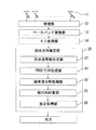
〔装置構成〕
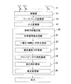
図1は、実施例1における到来方向推定装置の構成を示すブロック図である。実施例1における到来方向推定装置は、図1に示すように、センサアレイ11、受信部12、ベースバンド変換部13、アナログデジタル変換(以降、AD変換と表記)部14、到来方向推定部20等を含む。これら各処理ブロックはそれぞれハードウェア構成要素として実現される([その他]の項参照)。なお、これら各処理ブロックは、ソフトウェアの構成要素、又はハードウェア構成要素とソフトウェア構成要素との組み合わせとしてそれぞれ実現されてもよい([その他]の項参照)。
〔Device configuration〕
FIG. 1 is a block diagram illustrating the configuration of the arrival direction estimation apparatus according to the first embodiment. As shown in FIG. 1, the arrival direction estimation apparatus according to the first embodiment includes a
センサアレイ11は、異なる空間位置にそれぞれ配列されたN個のセンサ素子A1〜ANを有する。例えば、センサアレイ11は、各センサ素子が直線状に等間隔で配列された等間隔リニアアレイアンテナ(ULA(Uniform Linear Array) antenna)を形成する。各センサ素子は、到来信号(到来波)をそれぞれ受信する。実施例1における到来方向推定装置がレーダに搭載されている場合には、この到来信号は前記レーダの放射した送信信号がターゲットによって反射されて戻ってきたエコー信号となる。受信された各到来信号はそれぞれ受信部12へ送られる。なお、センサ素子の数Nは、受信アンテナとして作用するセンサ素子の数であって、複数の送信アンテナと複数の受信アンテナとを組み合わせて実効的な受信アンテナの数を拡大させる技術(以降、開口拡大技術と表記する)を用いた場合には実効的な受信アンテナ数に相当する。以降、Nを受信アンテナ数と表記する。
The
受信部12は、各センサ素子で受信された各信号に対してそれぞれ低雑音増幅を施す。受信部12はこのように処理された受信信号をベースバンド変換部13へ送る。ベースバンド変換部13は、各受信信号を送信波の一部とミキシングすることで各ベースバンド信号をそれぞれ生成する。実施例1における到来方向推定装置がレーダに搭載されている場合は、この送信波はターゲット探知用のプローブ信号となる。
The
AD変換部14は、このベースバンド信号を所定のサンプリング周期でサンプリングすることにより各デジタル信号にそれぞれ変換する。このように生成された各デジタル信号は到来方向推定部20へそれぞれ送られる。以降、到来方向推定部20へ送られるデジタル信号を合成エコー信号又は合成エコーと表記する。ここで用いる「合成」とは、各センサ由来のデジタル信号のそれぞれに、複数の目標からのエコー信号が重畳して含まれていることを意味する。
The
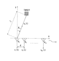
図2は、合成エコー信号を説明するための概念図である。図2は、センサアレイ11が受信アンテナ数N、素子間隔dの等間隔リニアアレーアンテナを形成する例を示す。図2は、M(≦N−1)個の独立した信号が、互いに異なる角度θm(m=1、2、…、M)
でそれぞれ入射される例を示す。なお、θmは、図2のY軸の方向を0度として時計回り
を正方向として測った角度である。
FIG. 2 is a conceptual diagram for explaining the synthesized echo signal. FIG. 2 shows an example in which the
An example in which each is incident is shown. Note that θ m is an angle measured with the direction of the Y axis in FIG. 2 as 0 degree and the clockwise direction as the positive direction.
ここで、時刻tにおいて、n番目の受信センサ素子で受信された信号から得られる合成エコー信号(vn(t))は、以下の式(1.1)で示すことができる。xm(t)は、m番目の目標からの到来信号(第m波)のベースバンド成分を示し、以降、目標エコー信号又は目標エコーと表記する。また、φn、mは空間位相情報(受信アンテナ素子nにおける第m波の受信位相)を示し、nn(t)は電力σの加法性ガウス雑音成分を示す。また、
λはキャリア信号(搬送波)の波長を示す。
Here, the synthesized echo signal (v n (t)) obtained from the signal received by the n-th receiving sensor element at time t can be expressed by the following equation (1.1). x m (t) indicates a baseband component of an incoming signal (m-th wave) from the m-th target, and is hereinafter referred to as a target echo signal or a target echo. Φ n and m indicate spatial phase information (the reception phase of the m-th wave at the receiving antenna element n), and n n (t) indicates an additive Gaussian noise component of the power σ. Also,
λ represents the wavelength of the carrier signal (carrier wave).

これにより、N個の受信センサ素子で受信された信号から得られる各合成エコー信号は、以下の式(1.3)で示されるようにベクトルv(t)として示すことができる。以降
、これを、合成エコー信号ベクトルと表記する。なお、式(1.3)から(1.6)において、n(t)は雑音ベクトルを、a(θm)はモードベクトル(方向ベクトル)を、上付
き添え字のTはベクトル又は行列の転置を示す。
Thereby, each synthetic echo signal obtained from the signals received by the N reception sensor elements can be represented as a vector v (t) as shown in the following equation (1.3). Hereinafter, this is referred to as a synthesized echo signal vector. In equations (1.3) to (1.6), n (t) is a noise vector, a (θ m ) is a mode vector (direction vector), and the superscript T is a vector or matrix. Indicates transposition.
到来方向推定部20は、各合成エコー信号をそれぞれ受けると、以下に示す各処理ブロックにより信号処理を施し、各目標エコー信号の到来方向(到来角度)を推定する。到来方向推定部20は、図1に示すように、到来信号数決定部21、一般化HANKEL行列生成部22、線形演算子計算部23、プロパゲータ行列計算部24、核行列計算部25、推定処理部26等を含む。これら処理ブロックは、それぞれハードウェア構成要素として実現される([その他]の項参照)。なお、これら各処理ブロックは、ソフトウェアの構成要素、又はハードウェア構成要素とソフトウェア構成要素との組み合わせとしてそれぞれ実現されてもよい([その他]の項参照)。以下、これら到来方向推定部20の各処理ブロックについてそれぞれ詳細に説明する。
Upon receiving each synthesized echo signal, the arrival
到来信号数決定部21は、目標数、即ち、到来信号数Mを決定する。到来信号数決定部21は、各合成エコー信号を用いた周知の目標数推定手法を用いて到来信号数Mを推定する。なお、この目標数推定手法は周知であるためここでは説明を省略する。到来信号数決定部21により決定された到来信号数Mは、一般化HANKEL行列生成部22へ送られ
る。
The incoming signal
一般化HANKEL行列生成部22は、送られた各合成エコー信号を示す合成エコー信号ベクトルを用いて、以下のように一般化HANKEL行列Rを生成する。
The generalized HANKEL
一般化HANKEL行列生成部22は、合成エコー信号ベクトルv(t)とそのL番目の成分の共役複素数vL *(t)との相関ベクトルrVLを求め、この相関ベクトルrVLから自己相関成分を取り除いたベクトルwLを生成する。自己相関成分を取り除くのは雑音成
分を除外するためである。相関ベクトルrVL及びwLは以下の式(2.2)及び式(2.3
)で表わされる。ここで、Lは、1以上N以下の自然数であり、E[・]は平均操作を示す。以降、相関ベクトルrVL及びwLの各要素は、同一複素共役成分毎に受信センサの配
列順に対応して並べられているものとして説明する。
The generalized HANKEL
). Here, L is a natural number of 1 or more and N or less, and E [•] indicates an average operation. Hereinafter, description will be made assuming that the elements of the correlation vectors r VL and w L are arranged corresponding to the arrangement order of the reception sensors for each identical complex conjugate component.
一般化HANKEL行列生成部22は、自己相関成分の取り除かれた相関ベクトルwL
から部分ベクトルwL(k)を抽出する。一般化HANKEL行列生成部22は、各部分
ベクトルwL(k)が受信アンテナ数Nから上記到来信号数Mを引いた数(N−M)の次
元(以降、必要次元と表記する)を持つように抽出する。一般化HANKEL行列生成部22は、上記相関ベクトルwLのうちの、同一複素共役成分を有する成分のうち、自己相
関成分までの連続して並ぶ成分の数が上記必要次元以上となる複数成分を要素とする部分ベクトル(以降、第1部分ベクトルと表記する)と、同一複素共役成分を有する成分のうち、自己相関成分より後の連続して並ぶ成分の数が上記必要次元以上となる複数成分を要素とする部分ベクトル(以降、第2部分ベクトルと表記する)と、を対象に部分ベクトルを抽出する。
The generalized
A partial vector w L (k) is extracted from. The generalized HANKEL
第1部分ベクトルを対象とする場合(N≧L≧N−M+1の場合)には、同一複素共役成分をそれぞれ有する各第1部分ベクトルから、自己相関成分を含まない連続して並ぶ上記必要次元の成分の各組み合わせがそれぞれ部分ベクトルとして抽出される。これにより抽出された部分ベクトルwL(k)は以下の式で示される。 When the first partial vector is targeted (when N ≧ L ≧ N−M + 1), the necessary dimensions are arranged in succession without including autocorrelation components from the first partial vectors each having the same complex conjugate component. Each combination of the components is extracted as a partial vector. The partial vector w L (k) extracted by this is expressed by the following equation.
第2部分ベクトルを対象とする場合(1≦L≦Mの場合)には、同一複素共役成分をそれぞれ有する各第2部分ベクトルから、自己相関成分を含まない連続して並ぶ上記必要次元の成分の各組み合わせがそれぞれ部分ベクトルとして抽出される。これにより抽出された部分ベクトルwL(k)は以下の式で示される。 When the second partial vector is a target (when 1 ≦ L ≦ M), components of the above-mentioned necessary dimensions that are continuously arranged and do not include an autocorrelation component from each second partial vector each having the same complex conjugate component Each combination is extracted as a partial vector. The partial vector w L (k) extracted by this is expressed by the following equation.
一般化HANKEL行列生成部22は、上記部分ベクトルwL(k)を並べることによ
り、以下の式(2.6)及び式(2.7)のような第1行列Rf1 L及び第2行列Rf2 Lを生成する。なお、以下の式(2.6)におけるL=Nの場合、及び、式(2.7)におけるL=1の場合には、零行列は付加されない。零行列は、次元調整のために、同一要素位置の各成分の位相関係が行列相互に同じになるように付加される。
The generalized HANKEL
一般化HANKEL行列生成部22は、上記第1行列Rf1 Lをそれぞれ加算することで
以下のようにFSS−一般化HANKEL行列Rf1を生成する。この加算により位相関係が同じ各成分(要素)がそれぞれ足しあわされる。同様に、一般化HANKEL行列生成部22は、上記第2行列Rf2 Lをそれぞれ加算することで以下のようにFSS−一般化H
ANKEL行列Rf2を生成する。
Generalized HANKEL
An ANKEL matrix R f2 is generated.
ここで、FSS−一般化HANKEL行列Rf1及びRf2は、第1行列Rf1 L及び第2行
列Rf2 Lが零行列で次元調整されているため、各列ベクトル間でベクトルの大きさが異な
る。そこで、一般化HANKEL行列生成部22は、各列ベクトルの大きさを合わせるために、以下のような((N−M)×M)次の係数行列GM1及びGM2と上記FSS−一般化HANKEL行列Rf1及びRf2とのアダマール積を算出する。アダマール積とは要素毎の積であり、(Hadamard)で示す。なお、計算量を削減したい場合等には、式(2.11)及
び式(2.13)を用いず、上記式(2.8)及び式(2.9)で算出されるFSS−一般
化HANKEL行列Rf1及びRf2をそのまま用いるようにしてもよい。但し、ベクトルの大きさを平均するアダマール積を用いた場合のほうが、角度推定の精度は向上する。
Here, in the FSS-generalized HANKEL matrices R f1 and R f2 , since the first matrix R f1 L and the second matrix R f2 L are dimensionally adjusted with a zero matrix, the magnitude of the vector between the column vectors is Different. Therefore, the generalized HANKEL
更に、精度を向上させ、受信センサの一部が故障した場合でも角度推定の計算が破綻しない様にするには、式(2.8)及び(2.9)の代わりに、以下の式(2.8a)及び式(2.9a)なるスカラを導入して、以下の式(2.8b)及び(2.9b)を生成する。そして、これらを対象として、上記式(2.10)から(2.13)を生成しても良い。 Further, in order to improve the accuracy and prevent the calculation of the angle estimation from failing even when a part of the receiving sensor fails, the following formula (instead of formulas (2.8) and (2.9): The scalars 2.8a) and (2.9a) are introduced to generate the following equations (2.8b) and (2.9b). And for these, the above formulas (2.10) to (2.13) may be generated.
なお、式(2.8a)及び式(2.9a)のスカラの分子は、それぞれのLの範囲のセンサの中で故障等によって利用できないセンサを除いて、例えば、一番小さいLと一番大きなLとに対応する信号で置き換えてもよい。 The scalar numerators of the formulas (2.8a) and (2.9a) are, for example, the smallest L and the smallest, except for sensors that cannot be used due to a failure or the like among the sensors in the respective L ranges. A signal corresponding to a large L may be replaced.
一般化HANKEL行列生成部22は、上述のように生成されたFSS−一般化HANKEL行列Rf1及びRf2を用いて以下のようにBSS−一般化HANKEL行列Rb1及びRb2を生成する。以下の式(2.14)及び(2.15)において、行列Rf1 *及びRf2 *は、FSS−一般化HANKEL行列Rf1及びRf2の各要素の共役複素数をそれぞれ要素とする行列であり、行列JN-Mは(N−M)次の反対角単位行列であり、行列JMはM次の反対角単位行列である。
Generalized HANKEL
一般化HANKEL行列生成部22は、上述のように生成されたFSS−一般化HANKEL行列Rf1及びRf2、BSS−一般化HANKEL行列Rb1及びRb2を用いて以下のように一般化HANKEL行列Rを生成する。一般化HANKEL行列生成部22は、生成された一般化HANKEL行列Rを線形演算子計算部24へ送る。
The generalized HANKEL
一般化HANKEL行列生成部22は、高い推定精度を実現するためには、式(2.1
6)に示すように一般化HANKEL行列Rを生成することが好ましいが、空間平均行列
Rf1、Rf2、Rb1及びRb2の少なくとも1つを用いて一般化HANKEL行列Rを生成するようにしてもよい。例えば、不具合により一部のセンサ素子から受信信号が得られず、式(2.8b)及び(2.9b)による補償を行っても、必要な全ての角度情報を持つ空間平均行列Rf1、Rf2、Rb1及びRb2のいずれかが生成できない場合には、正常に生成された空間平均行列のみを用いるようにすればよい。これにより、センサ素子等の機器に不具合が生じた場合であっても、到来方向推定に必要な位相を含む行列Rの全要素が欠損する可能性は低くなるため、到来方向推定機能が停止する可能性も低くなる。一般化HANKEL行列生成部22は、一般化HANKEL行列Rと共に、その一般化HANKEL行列Rに含まれる空間平均行列Rf1、Rf2、Rb1及びRb2の数Kを線形演算子計算部24へ通知するようにする。
In order to realize high estimation accuracy, the generalized HANKEL
Although it is preferred to generate the generalized HANKEL matrix R as shown in 6), so as to generate the generalized HANKEL matrix R using at least one spatial average matrix R f1, R f2, R b1 and R b2 May be. For example, a reception signal cannot be obtained from some sensor elements due to a malfunction, and even if compensation according to equations (2.8b) and (2.9b) is performed, a spatial average matrix R f1 having all necessary angle information, If any of R f2 , R b1, and R b2 cannot be generated, only a normally generated spatial average matrix may be used. As a result, even if a malfunction occurs in a device such as a sensor element, the possibility of losing all the elements of the matrix R including the phase necessary for arrival direction estimation is reduced, so the arrival direction estimation function stops. The possibility is also reduced. The generalized HANKEL
線形演算子計算部23は、一般化HANKEL行列生成部22から送られる一般化HANKEL行列Rをその行列Rを生成するために用いた空間平均行列の数Kに基づいて、以下のように、部分行列R1と部分行列R2とに分割する。一般化HANKEL行列Rは((N−M)×KM)の次元を持ち、部分行列R1は(M×KM)の次元を持ち、部分行列R2は((N−2M)×KM)の次元を持つ。線形演算子計算部23は、部分行列R1とR2とを用いて線形演算子Гを生成する。線形演算子計算部23は、生成された線形演算子Гをプロパゲータ行列計算部24へ送る。なお、式(3.2)等に現れる上付き添え字の−1は逆行列を示し、Hは複素共役転置を示す。
The linear
プロパゲータ行列計算部24は、線形演算子Гと(N−2M)次の単位行列IN-2Mとを
用いて、以下の式(3.3)に示すようにプロパゲータ行列Πを生成する。プロパゲータ
行列計算部24は、このプロパゲータ行列Πを核行列計算部25へ送る。また、プロパゲータ行列計算部24は、上記算出されたプロパゲータ行列Πから以下の式(3.4)に示
すように算出される直交化プロパゲータ行列Π’をプロパゲータ行列Πの替わりに核行列計算部25へ送るようにしてもよい。
The propagator
核行列計算部25は、プロパゲータ行列Π又は直交化プロパゲータ行列Π’を用いて以下のように核行列Ω1を生成する(式(3.5)又は式(3.6))。この生成された核行
列Ω1は、雑音部分空間への射影行列としての性質を持つ。核行列Ω1は(N−M)の次元を持つ。
The kernel
核行列計算部25は、式(3.5)又は式(3.6)で算出された核行列Ω1を用いて、
核行列Ω1と直交する核行列Ω2を算出する。これにより、核行列Ω2は、雑音部分空間の
への射影行列を示すΩ1に直交するため、信号部分空間への射影行列を示す。核行列計算
部25は、(N−M)次の単位行列IN-Mから上記のように算出された核行列Ω1を引くことにより核行列Ω2を算出する(式(3.7)参照)。核行列Ω2は(N−M)の次元を持
つ。
The kernel
Calculating a kernel matrix Omega 2 orthogonal to the kernel matrix Omega 1. Thereby, since the kernel matrix Ω 2 is orthogonal to Ω 1 indicating the projection matrix to the noise subspace, the kernel matrix Ω 2 represents the projection matrix to the signal subspace. The kernel
![]()
![]()
なお、式(3.7)で算出された核行列Ω2が核行列Ω1と直交することは、以下のよう
に証明することができる。まず、核行列Ω1は、以下の式(3.8)及び式(3.9)で示
される特性を有する。そして、核行列Ω1と核行列Ω2とが直交する場合には、以下の式(3.10)で示される関係が成立する。この式(3.10)の第2項の核行列Ω2に上記式
(3.7)を代入すれば、式(3.8)及び式(3.9)の関係に基づいて、式(3.11)のように核行列Ω2と核行列Ω1との直交関係が成立することを確認することができる。
It can be proved that the kernel matrix Ω 2 calculated by the equation (3.7) is orthogonal to the kernel matrix Ω 1 as follows. First, the kernel matrix Ω 1 has characteristics represented by the following formulas (3.8) and (3.9). When the kernel matrix Ω 1 and the kernel matrix Ω 2 are orthogonal, the relationship represented by the following formula (3.10) is established. Substituting the above equation (3.7) into the kernel matrix Ω 2 of the second term of this equation (3.10), the equation (3.8) and the equation (3.9) are used to obtain the equation ( It can be confirmed that the orthogonal relationship between the kernel matrix Ω 2 and the kernel matrix Ω 1 is established as in 3.11).
核行列計算部25は、算出された核行列Ω1及びΩ2を推定処理部26へ送る。
The kernel
推定処理部26は、核行列Ω1及びΩ2の少なくとも一方を分子にその他方を分母に用いた角度スペクトラムを算出する(勿論、分母分子の双方でΩ1とΩ2とを線形結合等で組み合わせて用いても良い)。以下の式(3.12)は、雑音部分空間への射影行列を示す核
行列Ω1を分母に、信号部分空間への射影行列を示す核行列Ω2を分子に用いて角度スペクトラムが算出される例を示す。推定処理部26は、この角度スペクトラムでモードベクトルのパラメータθを走査し、P(θ)がピークを示すθの値を取得することにより到来波
の到来角度を推定する。この場合、パラメータθを用いるモードベクトルa(θ)は、a
=d/λとして以下の式(3.13)で定義される。
The
= D / λ is defined by the following equation (3.13).
推定処理部26は、上述のような角度スペクトラムではなく、代数方程式を用いて到来波の到来角度を推定するようにしてもよい。この場合には、推定処理部26は、以下の式(3.14)を満足する解の候補zmを取得し、この候補zmを以下の式(3.15)のzに代入して得られる解が0に近似するzmを最終的に決定する。推定処理部26は、この決
定されたzmを以下の式(3.16)に代入することにより到来波の到来角度θmを推定す
る。
The
或いは、式(3.14a)で定義する有理関数、 Or a rational function defined by equation (3.14a),
のzに対する極値問題を解いて、極大値を与えるzの値から(3.16)式によって到来波の到来角度θmを推定しても良い。この場合の解法には、Newton法等の非線形最
適化手法が用いられる。
The arrival angle θ m of the arrival wave may be estimated from the value of z that gives the maximum value by solving the extreme value problem for z of (3). For the solution in this case, a nonlinear optimization method such as a Newton method is used.
〔実施例1における作用及び効果〕
実施例1における到来方向推定装置では、センサアレイ11のうちのN個のセンサ素子で受信された各受信信号から各ベースバンド信号、そして各デジタル信号がそれぞれ生成される(受信部12、ベースバンド変換部13、AD変換部14)。その後、到来方向推定部20の一般化HANKEL行列生成部22において、この各デジタル信号を要素に持つ合成エコー信号ベクトルv(t)の相関ベクトルから一般化HANKEL行列Rが生成される(一般化HANKEL行列生成部22)。
[Operation and Effect in Example 1]
In the arrival direction estimation apparatus according to the first embodiment, each baseband signal and each digital signal are generated from each reception signal received by the N sensor elements of the sensor array 11 (
線形演算子計算部23及びプロパゲータ行列計算部24において、この生成された一般化HANKEL行列Rの部分行列R1及びR2を用いた線形演算が実行されることで、線形演算子Г、及び、プロパゲータ行列Π又は直交化プロパゲータ行列Π’が生成される。こ
れら生成された行列が用いられることにより、核行列計算部25において、雑音部分空間への射影行列としての性質を有する核行列Ω1が生成され、この核行列Ω1と直交する核行列Ω2が生成される。結果、推定処理部26において、この核行列Ω1及びΩ2がそれぞれ
用いられて定義された角度スペクトラム、又は、代数方程式等から信号の到来方向が推定される。
In the linear
特に、角度スペクトラムにより推定される場合には、雑音部分空間への射影行列としての性質を有する核行列Ω1を分母に利用し、それに直交する、即ち、信号部分空間への射
影行列を示す核行列Ω2を分子に利用する。より一般的には、いずれか一方が分母で他方
が分子に利用される。これにより、実施例1において利用される角度スペクトラムP(θ)では、雑音部分空間における角度スペクトラムaH(θ)Ω1a(θ)が極小値を取る場合のモードベクトルa(θ)に対し、同時に信号部分空間に於ける角度スペクトラムaH
(θ)Ω2a(θ)が極大値を取るため、推定目標角度のピークが強調され、雑音に基づ
く偽ピークが抑圧される。
In particular, when estimated by an angular spectrum, a kernel matrix Ω 1 having a property as a projection matrix to a noise subspace is used as a denominator and orthogonal to it, that is, a kernel showing a projection matrix to a signal subspace. Use the matrix Ω 2 for the numerator. More generally, one is used for the denominator and the other for the numerator. As a result, in the angle spectrum P (θ) used in the first embodiment, with respect to the mode vector a (θ) when the angle spectrum a H (θ) Ω 1 a (θ) in the noise subspace takes a minimum value. At the same time, the angle spectrum a H in the signal subspace
Since (θ) Ω 2 a (θ) takes a maximum value, the peak of the estimated target angle is emphasized, and the false peak based on noise is suppressed.
従って、実施例1における到来方向推定装置によれば、高精度な到来方向推定を実現することができる。 Therefore, according to the arrival direction estimation apparatus in the first embodiment, it is possible to realize arrival direction estimation with high accuracy.
また、実施例1では、上述のような核行列Ω1及びΩ2を生成するのに利用される一般化HANKEL行列Rの要素となるFSS−一般化HANKEL行列Rf1及びRf2は以下のように生成される。 In the first embodiment, the FSS-generalized HANKEL matrices R f1 and R f2 which are elements of the generalized HANKEL matrix R used to generate the kernel matrices Ω 1 and Ω 2 as described above are as follows. Is generated.
一般化HANKEL行列生成部22において、合成エコー信号ベクトルv(t)とその各成分(要素)の共役複素数vL *(t)との相関ベクトルrVLが取得され、この相関ベクトルrVLから(N−M)次元の複数の部分ベクトル(wL(k))が抽出される。
In the generalized HANKEL
各部分ベクトルは、相関ベクトルrVLにおける同一複素共役成分毎に受信センサの配列順に対応して並べられた複数成分から、同一複素共役成分を有し自己相関成分を含まない連続して並ぶ(N−M)個の成分の組み合わせをそれぞれ要素に持つように抽出される。 Each partial vector is successively arranged from a plurality of components arranged corresponding to the arrangement order of the reception sensor for each identical complex conjugate component in the correlation vector r VL and having the same complex conjugate component and not including an autocorrelation component (N -M) Extraction is performed so that each element has a combination of components.
このように抽出された各部分ベクトルが同一複素共役成分を有するもの毎に並べられ、位相関係の合う成分同士が同じ要素位置となるように次元が合わせられた((N−M)×M)次の第1行列Rf1 L及び第2行列Rf2 Lが生成される。 The partial vectors extracted in this way are arranged for each having the same complex conjugate component, and the dimensions are matched so that components in phase relationship are at the same element position ((N−M) × M). The next first matrix R f1 L and second matrix R f2 L are generated.
第1行列Rf1 Lは、同一複素共役成分を有する成分のうち自己相関成分までの連続して
並ぶ複数成分から抽出された組み合わせを要素に持つ部分ベクトルから生成される。第2行列Rf2 Lは、同じ複素共役成分を有する複数成分のうち自己相関成分より後の連続して
並ぶ複数成分から抽出された組み合わせを要素に持つ部分ベクトルから生成される。第1行列Rf1 L及び第2行列Rf2 Lはそれぞれ足し合わされ、FSS−一般化HANKEL行列Rf1及びRf2が算出される。
The first matrix R f1 L is generated from a partial vector whose elements are combinations extracted from a plurality of components arranged in succession up to the autocorrelation component among components having the same complex conjugate component. The second matrix R f2 L is generated from a partial vector whose elements are combinations extracted from a plurality of consecutive components arranged after the autocorrelation component among a plurality of components having the same complex conjugate component. The first matrix R f1 L and the second matrix R f2 L are added together to calculate the FSS-generalized HANKEL matrices R f1 and R f2 .
このように、実施例1によれば、複数の複素共役成分を有する相関ベクトルの要素から空間平均行列が生成される。従って、実施例1によれば、低い周波数を持つ信号で変調されたプローブ信号を用いることにより、少ない測定回数での角度推定が求められている場合であっても、精度の高い角度推定を行うことができる。 Thus, according to the first embodiment, the spatial average matrix is generated from the elements of the correlation vector having a plurality of complex conjugate components. Therefore, according to the first embodiment, by using a probe signal modulated with a signal having a low frequency, angle estimation with high accuracy is performed even when angle estimation with a small number of measurements is required. be able to.
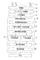
図3は、実施例2における到来方向推定装置の構成を示すブロック図である。実施例2における到来方向推定装置は、図3に示すように、実施例1の構成に加えて、更に、スケーリング行列計算部31を含む。以下、実施例2における到来方向推定装置について、実
施例1と異なる構成についてのみ説明する。
FIG. 3 is a block diagram illustrating the configuration of the arrival direction estimation apparatus according to the second embodiment. As shown in FIG. 3, the arrival direction estimation apparatus according to the second embodiment further includes a scaling
実施例2における到来信号数決定部21は、センサアレイ11で角度推定可能な最大の到来信号数を到来信号数Mに決定する。この場合、到来信号数Mは、例えば、(N−1)/2以下となる最大の自然数に決定される。到来信号数決定部21は、このように決定される到来信号数Mを固定値として予めメモリに保持するようにしてもよい。これにより、実施例2では、実施例1のような到来信号数推定処理が行われないため計算負荷を低減させることができる。
The arrival signal
このように、実施例2は、正確な到来信号数Mを用いることなく精度の高い角度推定を行うことができる。これは、以下に示すようなスケーリング行列が核行列を算出するにあたり利用されるからである。なお、実施例2においても、実施例1と同様に、到来信号数推定処理により正確な到来信号数Mが決定されるようにしてもよい。 Thus, Example 2 can perform highly accurate angle estimation without using the correct number M of incoming signals. This is because a scaling matrix as shown below is used to calculate the kernel matrix. In the second embodiment, as in the first embodiment, the accurate number of incoming signals M may be determined by the number of incoming signals estimation process.
スケーリング行列計算部31は、線形演算子計算部23から線形演算子Г及び部分行列R1及びR2を受け、これらを用いて以下の式(4.1)のようにスケーリング行列Λを生
成する。スケーリング行列計算部31は、算出されたスケーリング行列Λを核行列計算部25へ送る。
The scaling
核行列計算部25は、スケーリング行列計算部31からスケーリング行列Λ(式(4.
1))を受け、プロパゲータ行列計算部24からプロパゲータ行列Π(式(3.3))又
は直交化プロパゲータ行列Π’(式(3.4))を受ける。核行列計算部25は、スケー
リング行列Λとプロパゲータ行列Π又は直交化プロパゲータ行列Π’とから、以下のように核行列Ω1を算出する(式(4.2)又は式(4.3))。
The kernel
1)), and receives the propagator matrix Π (formula (3.3)) or the orthogonalized propagator matrix Π ′ (formula (3.4)) from the
核行列計算部25は、式(4.2)又は式(4.3)で算出された核行列Ω1を用いて、
核行列Ω1と直交する核行列Ω2を算出する。核行列Ω2の算出手法の例として、実施例2
では以下の2つの手法のいずれかが利用される。
The kernel
Calculating a kernel matrix Omega 2 orthogonal to the kernel matrix Omega 1. As an example of the calculation method of the kernel matrix Ω 2 , Example 2
Then, one of the following two methods is used.
〔第1算出手法〕
核行列計算部25は、第1算出手法では、例えば以下の式(4.4)を用いて核行列Ω2を算出する。
[First calculation method]
In the first calculation method, the kernel
以下、この式(4.4)の根拠を式(4.2)で示される核行列Ω1の例を用いて説明す
る。上述したように、核行列Ω1と核行列Ω2とが直交する場合には、上記式(3.10)
で示される関係が成立する。更に、核行列Ω1は、上記式(3.8)で示される特性を有し、プロパゲータ行列Πは、上記式(3.3)で示される。これら関係に基づいて上記式(
3.10)の第1項を計算すると、以下の式(4.5)が示される。
Hereinafter, the basis of the equation (4.4) will be described using an example of the kernel matrix Ω 1 represented by the equation (4.2). As described above, when the kernel matrix Ω 1 and the kernel matrix Ω 2 are orthogonal, the above equation (3.10)
The relationship indicated by is established. Further, the kernel matrix Ω 1 has the characteristic represented by the above formula (3.8), and the propagator matrix Π is represented by the above formula (3.3). Based on these relationships, the above formula (
When the first term of 3.10) is calculated, the following equation (4.5) is obtained.
核行列Ω2を核行列Ω1の部分行列と同じ次元の部分行列Ω2 11、Ω2 12、Ω2 21、Ω2 22に分割すると、核行列Ω2を求めるための方程式が以下の式(4.6)で示される。この方程式の第1列目及び第2列目からそれぞれ以下の式(4.7)及び式(4.8)の関係が得られる。 Nuclear matrix Omega 2 nuclear matrix Omega 1 same dimensions as partial matrix of the partial matrix Ω 2 11, Ω 2 12, Ω 2 21, when divided into Omega 2 22, equations of the following equation for determining the kernel matrix Omega 2 (4.6). From the first column and the second column of this equation, the following relations (4.7) and (4.8) are obtained, respectively.
式(4.7)及び式(4.8)の関係から、以下の式(4.9)及び(4.10)を満たす核行列Ω2の各部分行列をそれぞれ求めればよい。式(4.9)及び(4.10)において
各項に挟まれる記号は直交を示す。ここで、行列Λ-1がスカラとなる場合には、以下の式(4.11)及び(4.12)を満たす核行列Ω2の各部分行列をそれぞれ求めればよい。
上記式(3.2)に基づいて、式(4.4)の成分を下記式(4.11)及び(4.12)
に代入すれば、このΩ2が式(3.10)を満たす事は明らかである。式(4.11)及び(4.12)を満たすΩ2には様々な別解が存在し、それらを求める事は簡単であるが、一般的には、部分行列Ω2 11、Ω2 12、Ω2 21、Ω2 22に対する方程式とみなして、最小自乗法等で解いてもよい。
Each submatrix of the kernel matrix Ω 2 satisfying the following equations (4.9) and (4.10) may be obtained from the relationship between the equations (4.7) and (4.8). In the expressions (4.9) and (4.10), symbols between the terms indicate orthogonality. Here, if the matrix Λ −1 is a scalar, each submatrix of the kernel matrix Ω 2 that satisfies the following equations (4.11) and (4.12) may be obtained.
Based on the above formula (3.2), the components of the formula (4.4) are changed to the following formulas (4.11) and (4.12)
Substituting into, it is clear that this Ω 2 satisfies the formula (3.10). There are various alternative solutions for Ω 2 that satisfy the equations (4.11) and (4.12), and it is easy to find them, but in general, the sub-matrices Ω 2 11 , Ω 2 12 , Ω 2 21 , Ω 2 22 , and may be solved by the least square method or the like.
なお、Mを(N−1)/2以下となる最大の自然数とした場合、行列Λ-1の次元は最大でも2であるため、もし、行列Λ-1の次元が1を超える場合であっても、スケーリング行列Λ-1を固有値分解して、式(4.9)及び(4.10)の左項と直行する核行列Ω2の各
部分行列がそれぞれ取得されるようにすればよい。
Note that when M is the maximum natural number that is equal to or less than (N−1) / 2, the dimension of the matrix Λ −1 is 2 at the maximum, and therefore, the dimension of the matrix Λ −1 exceeds 1. However, the scaling matrix Λ −1 may be decomposed into eigenvalues so that the respective sub-matrices of the kernel matrix Ω 2 orthogonal to the left terms of the equations (4.9) and (4.10) are obtained. .
〔第2算出手法〕
核行列計算部25は、第2算出手法では以下の式(4.13)を用いて核行列Ω2を算出する。
[Second calculation method]
In the second calculation method, the kernel
以下、この式(4.13)の根拠を式(4.2)で示される核行列Ω1の例を用いて説明
する。到来信号が存在している角度位置ではプロパゲータの理論により式(4.14)が
成立することが知られている。よって、到来信号が存在している角度位置における、一般化HANKEL行列Rとこの行列Rの複素共役転置(エルミート共役転置)RHとの積は
、式(4.14)の関係及び上記式(3.1)の部分行列R1及びR2などを用いて式(4.
15)のように展開される。
Hereinafter, the basis of the equation (4.13) will be described using an example of the kernel matrix Ω 1 represented by the equation (4.2). It is known that the equation (4.14) is established by the propagator theory at an angular position where an incoming signal exists. Therefore, the product of the generalized HANKEL matrix R and the complex conjugate transpose (Hermitian conjugate transpose) R H of the matrix R at the angular position where the incoming signal exists is expressed by the relationship of the equation (4.14) and the above equation ( 3.1) using the sub-matrices R 1 and R 2 and the like (4.
15).
ここで、式(4.15)に含まれる、M次の単位行列IMと線形演算子Гとから構成される行列を以下の式(4.16)のように行列Σと定義すると、この行列
Σはプロパゲータ行列Πと直交することが式(4.17)のように示される。すなわち、
プロパゲータ行列Πが雑音部分空間への写像に対応しているのに対し、行列Σは、信号部分空間への写像に対応している事が分かる。従って、上記式(4.13)
により、核行列Ω1に直交する核行列Ω2を算出することができる。
Here, if a matrix composed of the M-th unit matrix I M and the linear operator Γ included in the equation (4.15) is defined as a matrix Σ as in the following equation (4.16), It is shown by the equation (4.17) that the matrix Σ is orthogonal to the propagator matrix Π. That is,
It can be seen that the propagator matrix Π corresponds to the mapping to the noise subspace, whereas the matrix Σ corresponds to the mapping to the signal subspace. Therefore, the above formula (4.13)
Thus, the kernel matrix Ω 2 orthogonal to the kernel matrix Ω 1 can be calculated.
ここで、本実施形態において行列Ω1とΩ2とが直交であるとは、以下のような場合も含むものとする。すなわち、第2算出手法では、式(4.2)で示されるΩ1を第1の核行列とし、式(4.13)で示されるΩ2を第2の核行列としたので、式(4.2)の最右辺
と式(4.13)とを用いて、直交関係の式(3.10)を計算すると、
Here, in the present embodiment, that the matrices Ω 1 and Ω 2 are orthogonal includes the following cases. That is, in the second calculation method, Ω 1 represented by equation (4.2) is the first kernel matrix, and Ω 2 represented by equation (4.13) is the second kernel matrix. Using the rightmost side of 4.2) and the equation (4.13), the equation (3.10) of the orthogonal relationship is calculated.
となる。この場合、Ω1、Ω2で部分空間との関係を決定する主要な行列Π、Σの間には直交関係が成り立つが、核行列Ω1、Ω2全体としては完全な直交
関係を満たさない。このような場合も、行列Ω1とΩ2とが実質的に直交であるものとする。
It becomes. In this case, an orthogonal relationship is established between the main matrices Π and Σ that determine the relationship with the subspace with Ω 1 and Ω 2 , but the nuclear matrices Ω 1 and Ω 2 as a whole do not satisfy the complete orthogonal relationship . Even in such a case, it is assumed that the matrices Ω 1 and Ω 2 are substantially orthogonal.
〔実施例2における作用及び効果〕
実施例2における到来方向推定装置では、到来信号数推定処理を行うことなく、センサアレイ11で角度推定可能な最大の到来信号数が到来信号数Mに決定され、この到来信号数Mを用いて到来方向推定が行われる。従って、実施例2によれば、到来信号数推定処理を省くことにより計算負荷を低減することができる。
[Operation and Effect in Example 2]
In the arrival direction estimation apparatus according to the second embodiment, the maximum number of arrival signals that can be estimated by the
実施例2における到来方向推定では、スケーリング行列計算部31において一般化HANKEL行列Rの部分行列R1及びR2、並びに線形演算子Гが利用されることにより、スケーリング行列Λ(式(4.1))が算出される。実施例2では、プロパゲータ行列Π又
は直交化プロパゲータ行列Π’に加えて、このスケーリング行列Λが利用されることで核行列Ω1が算出される。結果、この核行列Ω1とこれに直交する核行列Ω2とを用いて実施
例1と同様に到来方向が推定される。
In the direction-of-arrival estimation in the second embodiment, the scaling
これにより、実施例2によれば、信号の有無に極めて敏感に反応するスケーリング行列Λを利用して雑音部分空間への射影行列としての性質を有する核行列Ω1が算出されるた
め、正確な到来信号数Mが決定されない場合であっても、高い精度の到来方向推定を実現することができる。
Thus, according to the second embodiment, the kernel matrix Ω 1 having the property as a projection matrix onto the noise subspace is calculated using the scaling matrix Λ that reacts extremely sensitively to the presence or absence of a signal. Even when the number of incoming signals M is not determined, highly accurate arrival direction estimation can be realized.
[変形例1]
上述の実施例1及び2では、複数の複素共役成分を有する相関ベクトルの要素から空間平均行列(一般化HANKEL行列)が生成されていた。具体的には、実施例1及び2に
おける一般化HANKEL行列生成部22は、1以上N以下の自然数Lを用いて示される相関ベクトルrVL(式(2.1))を対象としてLの範囲に応じた第1行列Rf1 Lと第2行列Rf2 Lとを生成していた。変形例1では、HANKEL行列生成部22は、合成エコー
信号ベクトルv(t)とN番目の成分の共役複素数vN *(t)との相関ベクトルrVN、及び、v(t)と1番目の成分の共役複素数v1 *(t)との相関ベクトルrV1とを対象とする。このとき、一般化HANKEL行列生成部22は、以下の式(5.1a),(5.1b)で示される相関ベクトルrVN、rV1を生成する。
[Modification 1]
In the above-described first and second embodiments, a spatial average matrix (generalized HANKEL matrix) is generated from elements of a correlation vector having a plurality of complex conjugate components. Specifically, the generalized HANKEL
一般化HANKEL行列生成部22は、この相関ベクトルの要素を以下の式(5.2a
)、(5.2b)及び式(5.3a)、(5.3b)のように並べて行列Rf1,Rf2を生成
する。変形例1における一般化HANKEL行列生成部22は、更にこのように生成された行列Rf1,Rf2に対し、式(2.14)、(2.15)と同様にして行列Rb1,Rb2を求め、式(2.16)の様に並べて線形演算子計算部24へ送る一般化HANKEL行列Rとして用いる。以降、この一般化HANKEL行列Rを用いた到来方向推定手法については、上述の実施例1を用いてもよいし、実施例2を用いてもよい。
The generalized HANKEL
), (5.2b) and equations (5.3a), (5.3b) are arranged to generate matrices R f1 and R f2 . The generalized HANKEL
〔変形例1における作用及び効果〕
変形例1では、N番目と1番目の複素共役成分を有する相関ベクトルの要素から一般化HANKEL行列Rが生成され、この行列Rに基づいて到来方向推定が行われる。変形例1によれば、実施例1及び2と較べて一般化HANKEL行列Rを生成するために利用される相関ベクトルの要素は少なくなるものの、式(3.12)で示されるような核行列Ω1及びΩ2を用いた角度推定により高精度の到来方向推定を実現することができる。また、
変形例1によれば、相関ベクトルの扱われる要素数が少ないため計算量の削減という観点において有効である。
[Operation and Effect in Modification 1]
In the first modification, a generalized HANKEL matrix R is generated from the elements of the correlation vector having the Nth and first complex conjugate components, and the arrival direction estimation is performed based on the matrix R. According to the first modification, the number of elements of the correlation vector used for generating the generalized HANKEL matrix R is smaller than that in the first and second embodiments, but the kernel matrix as represented by the equation (3.12) is used. High-precision direction-of-arrival estimation can be realized by angle estimation using Ω 1 and Ω 2 . Also,
According to the first modification, since the number of elements handled by the correlation vector is small, it is effective from the viewpoint of reducing the amount of calculation.
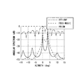
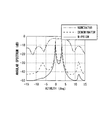
以下、図4及び5を用いて、変形例1における到来方向推定の効果について説明する。図4は、従来技術を用いた到来方向推定の角度スペクトラムを示すグラフである。図5は、変形例1における到来方向推定の角度スペクトラムを示すグラフである。なお、図4及び5に示すシミュレーションでは、第1ターゲットが相対距離40メートル(m)の角度0度に、第2ターゲットが相対距離40(m)の角度3度に存在するものと仮定している。また、相対速度については両ターゲットとも0(km/h)としている。 Hereinafter, the effect of direction-of-arrival estimation in Modification 1 will be described with reference to FIGS. FIG. 4 is a graph showing an angular spectrum of direction-of-arrival estimation using the prior art. FIG. 5 is a graph showing an angle spectrum of direction-of-arrival estimation in the first modification. In the simulations shown in FIGS. 4 and 5, it is assumed that the first target exists at an angle of 0 degree with a relative distance of 40 meters (m) and the second target exists at an angle of 3 degrees with a relative distance of 40 (m). Yes. The relative speed is set to 0 (km / h) for both targets.
図4には、従来技術を用いた到来方向推定の角度スペクトラムとして、DBF法(FFT−DBFと表記)、MUSIC法(FBSS−MUSICと表記)、先行技術文献の特許文献2で開示される技術(PRISMと表記)のそれぞれが示される。図4に示されるように、従来技術では、第1ターゲット及び第2ターゲットの位置に明確なピークを確認できるものの、その他の位置にも雑音に基づく偽ピークが存在する。 In FIG. 4, as an angle spectrum for direction-of-arrival estimation using the prior art, a DBF method (denoted as FFT-DBF), a MUSIC method (denoted as FBSS-MUSIC), and a technique disclosed in Patent Document 2 of the prior art document (Noted as PRISM) is shown. As shown in FIG. 4, in the related art, although clear peaks can be confirmed at the positions of the first target and the second target, false peaks based on noise exist at other positions.
図5には、変形例1における角度スペクトラム(M−PRISMと表記)と共に、上記式(3.12)における雑音部分空間の部分行列を示す核行列Ω1のみを分母に使った場合の角度スペクトラム(DENOMINATORと表記 − 分子はaH(θ)a(θ)であり、PRISMと同じ角度スペクトラムとなる)、信号部分空間の部分行列を示す核行列Ω2のみを分子に用いた場合の角度スペクトラム(NUMERATORと表記 − 分母
はスカラ1)がそれぞれ示される。図5に示す変形例1における角度スペクトラムによれば、図4に較べ、偽ピークのレベルが15デシベル(dB)近く改善し、第1ターゲット及び第2ターゲットの位置のピークが顕著に示される。これは、信号部分空間の情報を用いて角度推定しているからであると考えられる。具体的には、図5により、雑音空間において極小値を与えるモードベクトルが、同時に信号空間では極大値を与える、推定目標角度のピークが強調され、雑音に基づく偽ピークが抑圧されていることが理解できる。
FIG. 5 shows an angle spectrum when only the kernel matrix Ω 1 indicating the submatrix of the noise subspace in the above equation (3.12) is used as the denominator in addition to the angle spectrum (denoted as M-PRISM) in the first modification. (Denoted as DENOMINATOR-the numerator is a H (θ) a (θ) and has the same angular spectrum as PRISM), and the angular spectrum when only the nuclear matrix Ω 2 indicating the submatrix of the signal subspace is used for the numerator (Denoted as NUMERATOR-denominator is scalar 1) is shown respectively. According to the angular spectrum in Modification 1 shown in FIG. 5, the level of the false peak is improved by nearly 15 decibels (dB) compared to FIG. 4, and the peaks of the positions of the first target and the second target are markedly shown. This is presumably because the angle is estimated using information on the signal subspace. Specifically, according to FIG. 5, the mode vector that gives the minimum value in the noise space and the peak of the estimated target angle that gives the maximum value in the signal space at the same time are emphasized, and the false peak based on noise is suppressed. Understandable.
このように、変形例1のように、一般化HANKEL行列Rを生成するために利用される相関ベクトルの要素数が特許文献2と同様に少ない場合であっても、本実施形態によれば高精度の到来方向推定を実現することができる。これは、実施例1及び2に示すように、更に多くの要素を用いて平均効果を向上させた一般化HANKEL行列Rを用いれば、より高精度の到来方向推定を実現することができることを示すものでもある。 As described above, even when the number of elements of the correlation vector used for generating the generalized HANKEL matrix R is small as in the first modification, according to the present embodiment, the high Accurate direction-of-arrival estimation can be realized. This indicates that, as shown in the first and second embodiments, more accurate arrival direction estimation can be realized by using the generalized HANKEL matrix R that improves the average effect using more elements. It is also a thing.
[変形例2]
図6は、変形例2における到来方向推定装置の構成を示すブロック図である。変形例2における到来方向推定装置は、図6に示すように、実施例1における一般化HANKEL行列生成部22、線形演算子計算部23、プロパゲータ行列計算部24に替えて、FBSS(Forward Backward Spatial Smoothing)行列生成部41及び固有値分解処理部42を含む。変形例2における他の処理ブロックは、実施例1と同様である。
[Modification 2]
FIG. 6 is a block diagram illustrating a configuration of the arrival direction estimation apparatus according to the second modification. As shown in FIG. 6, the direction-of-arrival estimation apparatus according to the second modification is replaced with a generalized HANKEL
変形例2におけるFBSS行列生成部41は、合成エコー信号ベクトルv(t)から共分散行列RVVを算出する(式(6.1))。FBSS行列生成部41は、この行列RVVに
既知の技術である前後方空間平均(FBSS)を適用することにより、(L×L)次の行列RVV fbssを生成する。FBSS行列生成部41は、この行列RVV fbssを固有値分解処理部42へ送る。
The FBSS
固有値分解処理部42は、MUSIC(MUltiple SIgnal Classification)法で行われると同様に、行列RVV fbssを以下の式(6.2)で示すように固有値分解することにより
、行列ES及びENをそれぞれ取得する。行列ENは雑音固有空間を張る固有ベクトルから
構成される行列を示し、行列ESは信号固有空間を張る固有ベクトルから構成される行列
を示す。固有値分解処理部42は、取得された行列ES及びENを核行列計算部25へ送る。なお、行列ENの添え字Nは、受信アンテナ数Nを意味するものではない。
Similarly to the MUSIC (MUltiple SIgnal Classification) method, the eigenvalue
核行列計算部25は、行列ES及びENを用いて、以下の式(6.3)及び(6.4)に示す核行列Ω1及びΩ2を算出する。式(6.4)における単位行列ILの次元Lは、L≧(M+1)を示す。以降、推定処理部26により、このように算出された核行列Ω1及びΩ2が用いられることにより実施例1と同様に到来方向推定が行われる。このΩ1及びΩ2とが直交関係にあることは既知の事項であるから、ここでは説明を省略する。
The kernel
[変形例3]
実施例1及び2における到来方向推定装置において、推定処理部26は、核行列Ω1及
び核行列Ω2を用いて到来方向推定を行ったが、核行列Ω1のみを用いて以下の式(7.1
)により到来方向推定を行うようにしてもよい。核行列Ω1のみを用いた場合であっても
、核行列Ω1を生成するための一般化HANKEL行列Rが複数の複素共役成分を有する
相関ベクトルの要素から得られているため、高精度の到来方向推定を行うことができる。
[Modification 3]
In DOA estimating apparatus according to the first embodiment and 2,
) May be used to estimate the direction of arrival. Even when only the kernel matrix Ω 1 is used, the generalized HANKEL matrix R for generating the kernel matrix Ω 1 is obtained from the elements of the correlation vector having a plurality of complex conjugate components. Direction of arrival estimation can be performed.
[その他]
〈ハードウェアの構成要素(Component)及びソフトウェアの構成要素(Component)に
ついて〉
ハードウェアの構成要素とは、ハードウェア回路であり、例えば、フィールド・プログラマブル・ゲートアレイ(FPGA)、特定用途向け集積回路(ASIC)、ゲートアレイ、論理ゲートの組み合わせ、信号処理回路、アナログ回路等がある。
[Others]
<About hardware components (Component) and software components (Component)>
A hardware component is a hardware circuit, for example, a field programmable gate array (FPGA), an application specific integrated circuit (ASIC), a gate array, a combination of logic gates, a signal processing circuit, an analog circuit, etc. There is.
ソフトウェアの構成要素とは、ソフトウェアとして上記処理を実現する部品(断片)であり、そのソフトウェアを実現する言語、開発環境等を限定する概念ではない。ソフトウェアの構成要素としては、例えば、タスク、プロセス、スレッド、ドライバ、ファームウェア、データベース、テーブル、関数、プロシジャ、サブルーチン、プログラムコードの所定の部分、データ構造、配列、変数、パラメータ等がある。これらソフトウェアの構成要素は、1又は複数のメモリ(1または複数のプロセッサ(例えば、CPU(Central Processing Unit)、DSP(Digital Signal Processor)、GPGPU(General Purpose
Graphics Processing Unit)等)上で実現される。
A software component is a component (fragment) that realizes the above processing as software, and is not a concept that limits a language, a development environment, or the like that realizes the software. Examples of software components include tasks, processes, threads, drivers, firmware, databases, tables, functions, procedures, subroutines, predetermined portions of program code, data structures, arrays, variables, parameters, and the like. These software components include one or more memories (one or more processors (for example, CPU (Central Processing Unit), DSP (Digital Signal Processor), GPGPU (General Purpose)).
Graphics Processing Unit)).
なお、上述の各実施形態は、上記各処理部の実現手法を限定するものではない。上記各処理部は、上記ハードウェアの構成要素又はソフトウェアの構成要素若しくはこれらの組み合わせとして、本技術分野の通常の技術者において実現可能な手法により構成されていればよい。 In addition, each above-mentioned embodiment does not limit the realization method of each said process part. Each processing unit may be configured as a hardware component, a software component, or a combination thereof by a method that can be realized by a normal engineer in this technical field.
11 センサアレイ
12 受信部
13 ベースバンド変換部
14 アナログデジタル変換(AD変換)部
20 到来方向推定部
21 到来信号数決定部
22 一般化HANKEL行列生成部
23 線形演算子計算部
24 プロパゲータ行列計算部
25 核行列計算部
26 推定処理部
31 スケーリング行列計算部
41 FBSS(Forward Backward Spatial Smoothing)行列生成部
42 固有値分解処理部
DESCRIPTION OF
Claims (8)
前記一般化HANKEL行列Rの部分行列R1及びR2を用いて線形演算することにより雑音部分空間への射影行列としての性質を有する核行列Ω1を生成し、該核行列Ω1と直交する核行列Ω2を生成する第2行列生成部と、
前記核行列Ω1及びΩ2のいずれか一方を分子に他方を分母に用いて定義された角度スペクトラム、又は、前記核行列Ω1及びΩ2を用いた代数方程式から信号の到来方向を推定する推定部と、
を備えることを特徴とする到来方向推定装置。 A first matrix generation unit that generates a generalized HANKEL matrix R indicating a covariance matrix to which a spatial average is applied by using a correlation vector of a baseband signal vector obtained from each received signal received by a plurality of sensor elements; ,
Generates a kernel matrix Omega 1 having the properties of a projection matrix onto noise subspace, by performing linear operation using submatrices R 1 and R 2 of the generalized HANKEL matrix R, perpendicular to the nucleic matrix Omega 1 A second matrix generator for generating a kernel matrix Ω 2 ;
Estimate the direction of arrival of the signal from an angular spectrum defined using one of the kernel matrices Ω 1 and Ω 2 as the numerator and the other as the denominator, or from an algebraic equation using the kernel matrices Ω 1 and Ω 2 An estimation unit;
An arrival direction estimation apparatus comprising:
前記一般化HANKEL行列Rの部分行列R1及びR2を用いて線形演算子Г=(R1
R1 H)-1R1R2 H(−1は逆行列を示し、Hは複素共役転置を示す)を算出する演算子算
出部と、
前記線形演算子Гと単位行列Iとを用いてプロパゲータ行列Π=[Г、−I]T(Tは
転置を示す)又は直交化プロパゲータ行列Π'=Π(ΠHΠ)-1/2(−1/2は√を示す)を算出するプロパゲータ行列算出部と、
を含み、
前記核行列Ω1を前記プロパゲータ行列Π又は前記直交化プロパゲータ行列Π'を用いて算出する、
ことを特徴とする請求項1に記載の到来方向推定装置。 The second matrix generation unit includes:
Using the partial matrices R 1 and R 2 of the generalized HANKEL matrix R, the linear operator Γ = (R 1
An operator calculation unit for calculating R 1 H ) -1 R 1 R 2 H (-1 indicates an inverse matrix and H indicates a complex conjugate transpose);
Using the linear operator Γ and the unit matrix I, a propagator matrix Π = [Γ, −I] T (T indicates transposition) or an orthogonal propagator matrix Π ′ = Π (Π H Π) −1/2 ( A propagator matrix calculation unit for calculating (-1/2 indicates √),
Including
Calculating the kernel matrix Ω 1 using the propagator matrix Π or the orthogonalized propagator matrix Π ′;
The direction-of-arrival estimation apparatus according to claim 1.
前記一般化HANKEL行列Rの部分行列R1及びR2、並びに、前記線形演算子Гを用いてスケーリング行列Λ=R2R2 H−R2R1 HГを算出するスケーリング行列算出部を更に含み、
前記核行列Ω1を前記スケーリング行列Λの逆行列と共に前記プロパゲータ行列Π又は
前記直交化プロパゲータ行列Π’を用いて算出する、
ことを特徴とする請求項2に記載の到来方向推定装置。 The second matrix generation unit includes:
A scaling matrix calculator for calculating a scaling matrix Λ = R 2 R 2 H −R 2 R 1 H Γ using the sub-matrices R 1 and R 2 of the generalized HANKEL matrix R and the linear operator Γ; Including
The kernel matrix Ω 1 is calculated using the propagator matrix Π or the orthogonalized propagator matrix Π ′ together with the inverse matrix of the scaling matrix Λ.
The direction-of-arrival estimation apparatus according to claim 2.
ロパゲータ行列Π'を用いて算出された核行列と、前記スケーリング行列Λの逆行列と共
に前記プロパゲータ行列Π又は前記直交化プロパゲータ行列Π’を用いて算出された核行列と、を線形結合させることにより算出することを特徴とする請求項3に記載の到来方向推定装置。 The second matrix generator generates the kernel matrix Ω 1 from the propagator matrix Π or the orthogonalized propagator matrix Π ′ and the inverse matrix of the scaling matrix Λ together with the propagator matrix Π or The direction-of-arrival estimation apparatus according to claim 3, wherein the arrival direction estimation apparatus is calculated by linearly combining a kernel matrix calculated using the orthogonalized propagator matrix パ ′.
し合わせることで生成される第1行列Rf1及び第2行列群をそれぞれ足しあわされることで生成される第2行列Rf2の少なくとも1つを用いて前記一般化HANKEL行列Rを生成することを特徴とする請求項1から4のいずれか1項に記載の到来方向推定装置。 When the number of the plurality of sensor elements is N and the number of incoming signals received by the plurality of sensor elements is M, the first matrix generation unit includes a correlation vector of the baseband signal vectors. From a partial vector having a plurality of components having the same complex conjugate component and the number of components arranged in succession to the autocorrelation component being (N−M) or more, continuously including no autocorrelation component Each combination of (N−M) components arranged is extracted as each first partial vector, and among the correlation vectors, components having the same complex conjugate component and successively arranged after the autocorrelation component are extracted. Each combination of (N−M) components arranged in succession not including an autocorrelation component from the partial vectors having a plurality of components of which the number is (N−M) or more is used as each second partial vector. Extract and the The first partial vector and each second partial vector having the same complex conjugate component are arranged so that the components in phase relationship are in the same element position ((N−M) × M) It generates one matrix group and a second matrix group, the second matrix R f2 generated by the first matrix R f1 and the second matrix group be added up respectively generated by adding the first matrix group, respectively The direction-of-arrival estimation apparatus according to claim 1, wherein the generalized HANKEL matrix R is generated using at least one of the following.
前記一般化HANKEL行列Rの部分行列R1及びR2を用いて線形演算することにより雑音部分空間への射影行列としての性質を有する核行列Ω1を生成し、該核行列Ω1と直交する核行列Ω2を生成し、
前記核行列Ω1及びΩ2のいずれか一方を分子に他方を分母に用いて定義された角度スペクトラム、又は、前記核行列Ω1及びΩ2を用いた代数方程式から信号の到来方向を推定する、
ことを特徴とする到来方向推定方法。 Generating a generalized HANKEL matrix R indicating a covariance matrix to which a spatial average is applied by using a correlation vector of a baseband signal vector obtained from each received signal received by a plurality of sensor elements;
Generates a kernel matrix Omega 1 having the properties of a projection matrix onto noise subspace, by performing linear operation using submatrices R 1 and R 2 of the generalized HANKEL matrix R, perpendicular to the nucleic matrix Omega 1 Generate the kernel matrix Ω 2
Estimate the direction of arrival of the signal from an angular spectrum defined using one of the kernel matrices Ω 1 and Ω 2 as the numerator and the other as the denominator, or from an algebraic equation using the kernel matrices Ω 1 and Ω 2 ,
An arrival direction estimation method characterized by the above.
Priority Applications (3)
| Application Number | Priority Date | Filing Date | Title |
|---|---|---|---|
| JP2009201624A JP5659472B2 (en) | 2009-09-01 | 2009-09-01 | Direction of arrival estimation apparatus and method |
| US12/871,514 US8203485B2 (en) | 2009-09-01 | 2010-08-30 | Method of estimating direction of arrival and apparatus thereof |
| EP10174688.1A EP2293094B1 (en) | 2009-09-01 | 2010-08-31 | Method of estimating direction of arrival and apparatus thereof |
Applications Claiming Priority (1)
| Application Number | Priority Date | Filing Date | Title |
|---|---|---|---|
| JP2009201624A JP5659472B2 (en) | 2009-09-01 | 2009-09-01 | Direction of arrival estimation apparatus and method |
Publications (2)
| Publication Number | Publication Date |
|---|---|
| JP2011053056A JP2011053056A (en) | 2011-03-17 |
| JP5659472B2 true JP5659472B2 (en) | 2015-01-28 |
Family
ID=43064331
Family Applications (1)
| Application Number | Title | Priority Date | Filing Date |
|---|---|---|---|
| JP2009201624A Expired - Fee Related JP5659472B2 (en) | 2009-09-01 | 2009-09-01 | Direction of arrival estimation apparatus and method |
Country Status (3)
| Country | Link |
|---|---|
| US (1) | US8203485B2 (en) |
| EP (1) | EP2293094B1 (en) |
| JP (1) | JP5659472B2 (en) |
Families Citing this family (51)
| Publication number | Priority date | Publication date | Assignee | Title |
|---|---|---|---|---|
| WO2011107825A1 (en) * | 2010-03-01 | 2011-09-09 | Nokia Corporation | Method, and apparatus for determining the position using radio signals |
| JP5701083B2 (en) * | 2011-02-01 | 2015-04-15 | 富士通テン株式会社 | Radar device and method for calculating received power in the radar device |
| JP5628732B2 (en) * | 2011-04-04 | 2014-11-19 | 富士通テン株式会社 | Arithmetic apparatus for radar apparatus, radar apparatus, arithmetic method and program for radar apparatus |
| CN102520399B (en) * | 2012-01-02 | 2013-09-25 | 西安电子科技大学 | Electromagnetic vector array based angle estimation method for metric-wave radar |
| JP2013242151A (en) * | 2012-05-17 | 2013-12-05 | Mitsubishi Electric Corp | Digital beam forming (dbf) signal process device and process method of the same |
| CN103197294B (en) * | 2013-03-03 | 2014-10-01 | 西安电子科技大学 | Elevation angle estimating method of multi-frequency fusion maximum likelihood low-altitude target |
| US9759806B2 (en) * | 2013-06-13 | 2017-09-12 | Panasonic Corporation | Radar apparatus |
| EP2819025A1 (en) * | 2013-06-24 | 2014-12-31 | Université de Strasbourg | Method for reducing noise in data-sets of harmonic signals |
| CN105303009A (en) * | 2014-05-30 | 2016-02-03 | 西安电子科技大学 | Super-resolution spectrum estimation method based on compressed sensing and regular MFOCUSS |
| KR101639119B1 (en) * | 2014-06-13 | 2016-07-12 | 재단법인대구경북과학기술원 | Method and apparatus for processing radar signal |
| KR101592105B1 (en) * | 2014-06-23 | 2016-02-04 | 재단법인대구경북과학기술원 | Method and apparatus for processing radar signal |
| CN104345306B (en) * | 2014-11-03 | 2017-01-25 | 西安电子科技大学 | Target wave arrival angle estimation method based on Khatri-Rao subspace |
| KR101674747B1 (en) * | 2014-11-18 | 2016-11-09 | 재단법인대구경북과학기술원 | Apparatus and method for processing radar signal with in-phase/quadrature-phase imbalance |
| KR101564192B1 (en) | 2015-01-21 | 2015-10-28 | 홍익대학교 산학협력단 | Sliding-vector based apparatus and method with autocorrelation matrix for direction-of-arrival estimation with uniform linear array antenna systems |
| JP6293073B2 (en) * | 2015-02-02 | 2018-03-14 | 三菱電機株式会社 | Arrival direction estimation apparatus and arrival direction estimation method |
| KR101559270B1 (en) | 2015-02-04 | 2015-10-12 | 홍익대학교 산학협력단 | Low-complexity sliding-vector based apparatus and method with autocorrelation matrix for direction-of-arrival estimation with uniform linear array antenna systems |
| KR101557259B1 (en) | 2015-03-03 | 2015-10-13 | 홍익대학교 산학협력단 | Improved sliding-vector based apparatus and method with autocorrelation matrix for direction-of-arrival estimation with uniform linear array antenna systems |
| CN104933290B (en) * | 2015-04-29 | 2017-11-21 | 陕西理工学院 | Multi-parameter Combined estimator quaternary counting method of the double L-shaped orthogonal galvanic couple of stretching to array |
| KR101683827B1 (en) * | 2015-08-12 | 2016-12-07 | 홍익대학교 산학협력단 | Low-Complexity Sliding-Vector based Apparatus and Method with Sampling Technique for Direction-of-Arrival Estimation with Uniform Linear Array Antenna Systems |
| BE1023212B1 (en) * | 2015-11-20 | 2016-12-21 | Christopher RAUCY | Method and device for measuring the direction of RF sources |
| CN105807252B (en) * | 2016-03-14 | 2018-08-07 | 上海大学 | Direction of arrival estimation method based on squaerial array |
| CN106019252B (en) * | 2016-05-18 | 2018-09-21 | 西安电子科技大学 | A kind of based on Nested arrays and poor Tracking Angle Measurement method |
| CN106093869A (en) * | 2016-05-27 | 2016-11-09 | 上海无线电设备研究所 | Periodicity based on terrain parameter table synthesis steering vector maximum likelihood algorithm |
| CN106226754B (en) * | 2016-08-22 | 2019-03-29 | 西安电子科技大学 | Low elevation angle Wave arrival direction estimating method based on time reversal |
| CN106569180B (en) * | 2016-11-10 | 2020-01-21 | 中国人民解放军理工大学 | Prony method-based orientation estimation algorithm |
| CN106872933B (en) * | 2017-01-22 | 2019-08-20 | 南京航空航天大学 | A kind of electromagnetic vector sensor array element posture position 6 DOF error self-correcting method |
| KR102001394B1 (en) * | 2017-07-12 | 2019-07-18 | 서울대학교산학협력단 | Method of estimating DOA of received signals based on logarithmic-domain antenna array interpolation, and apparatus for the same |
| US10613212B2 (en) | 2017-08-14 | 2020-04-07 | Oculii Corp. | Systems and methods for doppler-enhanced radar tracking |
| EP3746809A4 (en) * | 2018-01-30 | 2021-09-29 | Oculii Corp | Systems and methods for virtual aperature radar tracking |
| US10564277B2 (en) | 2018-01-30 | 2020-02-18 | Oculii Corp. | Systems and methods for interpolated virtual aperature radar tracking |
| CN108761380B (en) * | 2018-05-23 | 2022-05-03 | 西安电子科技大学 | Target direction of arrival estimation method for improving precision |
| WO2019227353A1 (en) * | 2018-05-30 | 2019-12-05 | Goertek Inc. | Method and device for estimating a direction of arrival |
| US11079465B2 (en) * | 2018-10-30 | 2021-08-03 | Electronics And Telecommunications Research Institute | Method and apparatus for estimating location of signal source |
| CN109507634B (en) * | 2018-11-08 | 2020-08-11 | 中国电子科技集团公司第二十八研究所 | Blind far-field signal direction-of-arrival estimation method based on propagation operator under any sensor array |
| CN109581275B (en) * | 2018-12-13 | 2023-09-29 | 华南理工大学 | Two-dimensional underwater DOA estimation method and device based on non-circular signal and three-dimensional orthogonal array |
| CN110146842B (en) * | 2019-06-14 | 2020-12-01 | 哈尔滨工业大学 | Signal carrier frequency and two-dimensional DOA parameter estimation method based on undersampling |
| CN110244260B (en) * | 2019-06-17 | 2021-06-29 | 杭州电子科技大学 | Underwater target high-precision DOA estimation method based on acoustic energy flow vector compensation |
| CN110954859B (en) * | 2019-11-22 | 2023-04-07 | 宁波大学 | L-shaped array-based two-dimensional incoherent distributed non-circular signal parameter estimation method |
| CN110927659B (en) * | 2019-11-25 | 2022-01-14 | 长江大学 | Method and system for estimating arbitrary array manifold DOA (direction of arrival) under cross-coupling condition and cross-coupling calibration |
| US11047974B1 (en) | 2019-12-13 | 2021-06-29 | Oculii Corp. | Systems and methods for virtual doppler and/or aperture enhancement |
| CN110954860B (en) * | 2019-12-18 | 2021-06-29 | 金陵科技学院 | DOA and polarization parameter estimation method |
| US11041940B1 (en) | 2019-12-20 | 2021-06-22 | Oculii Corp. | Systems and methods for phase-modulated radar detection |
| WO2021243529A1 (en) * | 2020-06-01 | 2021-12-09 | 华为技术有限公司 | Method and apparatus for estimating angle of arrival aoa |
| US11280879B2 (en) | 2020-06-16 | 2022-03-22 | Oculii Corp. | System and method for radar interference mitigation |
| CN111781593A (en) * | 2020-07-09 | 2020-10-16 | 深圳大学 | Low data volume coherent signal DOA estimation method, device, equipment and medium |
| US11841420B2 (en) | 2020-11-16 | 2023-12-12 | Oculii Corp. | System and method for radar-based localization and/or mapping |
| CN112986919B (en) * | 2021-02-10 | 2023-08-18 | 西南电子技术研究所(中国电子科技集团公司第十研究所) | High-density DBF multipath multi-target signal processing device |
| CN113625220A (en) * | 2021-06-28 | 2021-11-09 | 台州学院 | New method for quickly estimating direction of arrival and diffusion angle of multipath signal |
| CN113887509B (en) * | 2021-10-25 | 2022-06-03 | 济南大学 | Rapid multi-modal video face recognition method based on image set |
| US11561299B1 (en) | 2022-06-03 | 2023-01-24 | Oculii Corp. | System and method for multi-waveform radar tracking |
| DE202022105574U1 (en) | 2022-10-01 | 2022-10-20 | Veerendra Dakulagi | A system for classifying multiple signals for direction of arrival estimation |
Family Cites Families (13)
| Publication number | Priority date | Publication date | Assignee | Title |
|---|---|---|---|---|
| US6288672B1 (en) | 1998-09-14 | 2001-09-11 | Kabushiki Kaisha Toyota Chuo Kenkyusho | Holographic radar |
| JP3368874B2 (en) | 1998-09-14 | 2003-01-20 | 株式会社豊田中央研究所 | Holographic radar |
| US6351238B1 (en) | 1999-02-23 | 2002-02-26 | Matsushita Electric Industrial Co., Ltd. | Direction of arrival estimation apparatus and variable directional signal receiving and transmitting apparatus using the same |
| JP4401526B2 (en) | 2000-01-24 | 2010-01-20 | パナソニック株式会社 | Radio wave arrival direction estimation device and directivity variable transmission / reception device |
| JP2004104620A (en) | 2002-09-11 | 2004-04-02 | Ricoh Co Ltd | Image reader |
| JP4339801B2 (en) | 2003-05-22 | 2009-10-07 | 富士通株式会社 | Direction-of-arrival estimation method and reception beam forming apparatus without using eigenvalue decomposition |
| WO2005001504A1 (en) | 2003-06-25 | 2005-01-06 | Fujitsu Limited | Method and apparatus for estimating wave arrival direction |
| US7574333B2 (en) * | 2004-02-05 | 2009-08-11 | Honeywell International Inc. | Apparatus and method for modeling relationships between signals |
| EP1777539B1 (en) | 2004-08-12 | 2013-01-09 | Fujitsu Limited | Radio wave arrival direction adaptive deduction tracking method and device |
| JP2006067869A (en) | 2004-09-01 | 2006-03-16 | Matsushita Electric Ind Co Ltd | Separating and recovering method |
| JP4833534B2 (en) | 2004-09-29 | 2011-12-07 | 富士通株式会社 | Radar equipment |
| WO2006067857A1 (en) * | 2004-12-24 | 2006-06-29 | Fujitsu Limited | Arrival direction estimating device and program |
| JP5320792B2 (en) | 2008-03-28 | 2013-10-23 | 富士通株式会社 | Arrival direction estimation apparatus, arrival direction estimation method, and arrival direction estimation program |
-
2009
- 2009-09-01 JP JP2009201624A patent/JP5659472B2/en not_active Expired - Fee Related
-
2010
- 2010-08-30 US US12/871,514 patent/US8203485B2/en not_active Expired - Fee Related
- 2010-08-31 EP EP10174688.1A patent/EP2293094B1/en not_active Not-in-force
Also Published As
| Publication number | Publication date |
|---|---|
| JP2011053056A (en) | 2011-03-17 |
| US8203485B2 (en) | 2012-06-19 |
| EP2293094B1 (en) | 2016-11-02 |
| US20110050500A1 (en) | 2011-03-03 |
| EP2293094A1 (en) | 2011-03-09 |
Similar Documents
| Publication | Publication Date | Title |
|---|---|---|
| JP5659472B2 (en) | Direction of arrival estimation apparatus and method | |
| US10854992B2 (en) | Radar device | |
| JP5617334B2 (en) | Radar apparatus and target detection method | |
| CN109283536B (en) | Multi-beam sounding sonar water body imaging beam forming method | |
| JP4559438B2 (en) | Direction of arrival estimation apparatus and program | |
| JP2021505892A (en) | Radar processing chain for FMCW radar system | |
| JP2006258529A (en) | Device and method for estimating radio wave incoming direction | |
| KR101953697B1 (en) | Method and apparatus for estimating direction of arrival using generation of virtual received signals based on uniform linear array antenna | |
| JP4757629B2 (en) | Arrival direction estimation device | |
| JP6362262B2 (en) | Angle estimation apparatus and angle estimation method | |
| JP2019168255A (en) | Pulse compression radar device and radar signal processing method therefor | |
| JP5134878B2 (en) | Radar equipment | |
| JP2010286403A (en) | Angle measuring system, monopulse angle measuring system, monopulse radar, multistatic radar | |
| RU2515179C1 (en) | Method of determining direction of hydroacoustic transponder in multibeam navigation signal propagation conditions | |
| Xu et al. | Joint Doppler and DOA estimation using (Ultra-) Wideband FMCW signals | |
| JP6246338B2 (en) | Angle measuring device and angle measuring method | |
| US11754671B2 (en) | Incoming wave count estimation apparatus and incoming wave count incoming direction estimation apparatus | |
| RU2491569C2 (en) | Method of direction finding with increased resolution ability | |
| KR102099388B1 (en) | Method of estimating direction of arrival of radar signal based on antenna array extrapolation and apparatus for the same | |
| JPH11133130A (en) | Radio wave incoming direction detecting apparatus and fm-cw radar | |
| JP2015129695A (en) | Pulse compression radar device and radar signal processing method therefor | |
| CN114488142A (en) | Radar two-dimensional angle imaging method and system based on difference-sum beam | |
| WO2020148802A1 (en) | Beam formation device, radar device, and beam formation method | |
| WO2020049717A1 (en) | Signal processing circuit, radar device, signal processing method, and signal processing program | |
| JP7434214B2 (en) | Signal processing device, radar device and signal processing method |
Legal Events
| Date | Code | Title | Description |
|---|---|---|---|
| A621 | Written request for application examination |
Free format text: JAPANESE INTERMEDIATE CODE: A621 Effective date: 20120510 |
|
| A977 | Report on retrieval |
Free format text: JAPANESE INTERMEDIATE CODE: A971007 Effective date: 20140117 |
|
| A131 | Notification of reasons for refusal |
Free format text: JAPANESE INTERMEDIATE CODE: A131 Effective date: 20140212 |
|
| TRDD | Decision of grant or rejection written | ||
| A01 | Written decision to grant a patent or to grant a registration (utility model) |
Free format text: JAPANESE INTERMEDIATE CODE: A01 Effective date: 20141104 |
|
| A61 | First payment of annual fees (during grant procedure) |
Free format text: JAPANESE INTERMEDIATE CODE: A61 Effective date: 20141117 |
|
| R150 | Certificate of patent or registration of utility model |
Ref document number: 5659472 Country of ref document: JP Free format text: JAPANESE INTERMEDIATE CODE: R150 |
|
| LAPS | Cancellation because of no payment of annual fees |