US11017705B2 - Color display device including multiple pixels for driving three-particle electrophoretic media - Google Patents
Color display device including multiple pixels for driving three-particle electrophoretic media Download PDFInfo
- Publication number
- US11017705B2 US11017705B2 US16/412,684 US201916412684A US11017705B2 US 11017705 B2 US11017705 B2 US 11017705B2 US 201916412684 A US201916412684 A US 201916412684A US 11017705 B2 US11017705 B2 US 11017705B2
- Authority
- US
- United States
- Prior art keywords
- particles
- composition
- electrophoretic fluid
- display
- type
- Prior art date
- Legal status (The legal status is an assumption and is not a legal conclusion. Google has not performed a legal analysis and makes no representation as to the accuracy of the status listed.)
- Active, expires
Links
Images


Classifications
-
- G—PHYSICS
- G02—OPTICS
- G02B—OPTICAL ELEMENTS, SYSTEMS OR APPARATUS
- G02B26/00—Optical devices or arrangements for the control of light using movable or deformable optical elements
- G02B26/004—Optical devices or arrangements for the control of light using movable or deformable optical elements based on a displacement or a deformation of a fluid
- G02B26/005—Optical devices or arrangements for the control of light using movable or deformable optical elements based on a displacement or a deformation of a fluid based on electrowetting
-
- G—PHYSICS
- G02—OPTICS
- G02B—OPTICAL ELEMENTS, SYSTEMS OR APPARATUS
- G02B26/00—Optical devices or arrangements for the control of light using movable or deformable optical elements
- G02B26/007—Optical devices or arrangements for the control of light using movable or deformable optical elements the movable or deformable optical element controlling the colour, i.e. a spectral characteristic, of the light
-
- G—PHYSICS
- G02—OPTICS
- G02B—OPTICAL ELEMENTS, SYSTEMS OR APPARATUS
- G02B26/00—Optical devices or arrangements for the control of light using movable or deformable optical elements
- G02B26/02—Optical devices or arrangements for the control of light using movable or deformable optical elements for controlling the intensity of light
- G02B26/026—Optical devices or arrangements for the control of light using movable or deformable optical elements for controlling the intensity of light based on the rotation of particles under the influence of an external field, e.g. gyricons, twisting ball displays
-
- G—PHYSICS
- G02—OPTICS
- G02F—OPTICAL DEVICES OR ARRANGEMENTS FOR THE CONTROL OF LIGHT BY MODIFICATION OF THE OPTICAL PROPERTIES OF THE MEDIA OF THE ELEMENTS INVOLVED THEREIN; NON-LINEAR OPTICS; FREQUENCY-CHANGING OF LIGHT; OPTICAL LOGIC ELEMENTS; OPTICAL ANALOGUE/DIGITAL CONVERTERS
- G02F1/00—Devices or arrangements for the control of the intensity, colour, phase, polarisation or direction of light arriving from an independent light source, e.g. switching, gating or modulating; Non-linear optics
- G02F1/01—Devices or arrangements for the control of the intensity, colour, phase, polarisation or direction of light arriving from an independent light source, e.g. switching, gating or modulating; Non-linear optics for the control of the intensity, phase, polarisation or colour
- G02F1/13—Devices or arrangements for the control of the intensity, colour, phase, polarisation or direction of light arriving from an independent light source, e.g. switching, gating or modulating; Non-linear optics for the control of the intensity, phase, polarisation or colour based on liquid crystals, e.g. single liquid crystal display cells
- G02F1/133—Constructional arrangements; Operation of liquid crystal cells; Circuit arrangements
- G02F1/13306—Circuit arrangements or driving methods for the control of single liquid crystal cells
-
- G—PHYSICS
- G02—OPTICS
- G02F—OPTICAL DEVICES OR ARRANGEMENTS FOR THE CONTROL OF LIGHT BY MODIFICATION OF THE OPTICAL PROPERTIES OF THE MEDIA OF THE ELEMENTS INVOLVED THEREIN; NON-LINEAR OPTICS; FREQUENCY-CHANGING OF LIGHT; OPTICAL LOGIC ELEMENTS; OPTICAL ANALOGUE/DIGITAL CONVERTERS
- G02F1/00—Devices or arrangements for the control of the intensity, colour, phase, polarisation or direction of light arriving from an independent light source, e.g. switching, gating or modulating; Non-linear optics
- G02F1/01—Devices or arrangements for the control of the intensity, colour, phase, polarisation or direction of light arriving from an independent light source, e.g. switching, gating or modulating; Non-linear optics for the control of the intensity, phase, polarisation or colour
- G02F1/165—Devices or arrangements for the control of the intensity, colour, phase, polarisation or direction of light arriving from an independent light source, e.g. switching, gating or modulating; Non-linear optics for the control of the intensity, phase, polarisation or colour based on translational movement of particles in a fluid under the influence of an applied field
- G02F1/166—Devices or arrangements for the control of the intensity, colour, phase, polarisation or direction of light arriving from an independent light source, e.g. switching, gating or modulating; Non-linear optics for the control of the intensity, phase, polarisation or colour based on translational movement of particles in a fluid under the influence of an applied field characterised by the electro-optical or magneto-optical effect
- G02F1/167—Devices or arrangements for the control of the intensity, colour, phase, polarisation or direction of light arriving from an independent light source, e.g. switching, gating or modulating; Non-linear optics for the control of the intensity, phase, polarisation or colour based on translational movement of particles in a fluid under the influence of an applied field characterised by the electro-optical or magneto-optical effect by electrophoresis
-
- G—PHYSICS
- G02—OPTICS
- G02F—OPTICAL DEVICES OR ARRANGEMENTS FOR THE CONTROL OF LIGHT BY MODIFICATION OF THE OPTICAL PROPERTIES OF THE MEDIA OF THE ELEMENTS INVOLVED THEREIN; NON-LINEAR OPTICS; FREQUENCY-CHANGING OF LIGHT; OPTICAL LOGIC ELEMENTS; OPTICAL ANALOGUE/DIGITAL CONVERTERS
- G02F1/00—Devices or arrangements for the control of the intensity, colour, phase, polarisation or direction of light arriving from an independent light source, e.g. switching, gating or modulating; Non-linear optics
- G02F1/01—Devices or arrangements for the control of the intensity, colour, phase, polarisation or direction of light arriving from an independent light source, e.g. switching, gating or modulating; Non-linear optics for the control of the intensity, phase, polarisation or colour
- G02F1/165—Devices or arrangements for the control of the intensity, colour, phase, polarisation or direction of light arriving from an independent light source, e.g. switching, gating or modulating; Non-linear optics for the control of the intensity, phase, polarisation or colour based on translational movement of particles in a fluid under the influence of an applied field
- G02F1/1675—Constructional details
-
- G—PHYSICS
- G02—OPTICS
- G02F—OPTICAL DEVICES OR ARRANGEMENTS FOR THE CONTROL OF LIGHT BY MODIFICATION OF THE OPTICAL PROPERTIES OF THE MEDIA OF THE ELEMENTS INVOLVED THEREIN; NON-LINEAR OPTICS; FREQUENCY-CHANGING OF LIGHT; OPTICAL LOGIC ELEMENTS; OPTICAL ANALOGUE/DIGITAL CONVERTERS
- G02F1/00—Devices or arrangements for the control of the intensity, colour, phase, polarisation or direction of light arriving from an independent light source, e.g. switching, gating or modulating; Non-linear optics
- G02F1/01—Devices or arrangements for the control of the intensity, colour, phase, polarisation or direction of light arriving from an independent light source, e.g. switching, gating or modulating; Non-linear optics for the control of the intensity, phase, polarisation or colour
- G02F1/165—Devices or arrangements for the control of the intensity, colour, phase, polarisation or direction of light arriving from an independent light source, e.g. switching, gating or modulating; Non-linear optics for the control of the intensity, phase, polarisation or colour based on translational movement of particles in a fluid under the influence of an applied field
- G02F1/1685—Operation of cells; Circuit arrangements affecting the entire cell
-
- G—PHYSICS
- G09—EDUCATION; CRYPTOGRAPHY; DISPLAY; ADVERTISING; SEALS
- G09G—ARRANGEMENTS OR CIRCUITS FOR CONTROL OF INDICATING DEVICES USING STATIC MEANS TO PRESENT VARIABLE INFORMATION
- G09G3/00—Control arrangements or circuits, of interest only in connection with visual indicators other than cathode-ray tubes
- G09G3/20—Control arrangements or circuits, of interest only in connection with visual indicators other than cathode-ray tubes for presentation of an assembly of a number of characters, e.g. a page, by composing the assembly by combination of individual elements arranged in a matrix no fixed position being assigned to or needed to be assigned to the individual characters or partial characters
- G09G3/34—Control arrangements or circuits, of interest only in connection with visual indicators other than cathode-ray tubes for presentation of an assembly of a number of characters, e.g. a page, by composing the assembly by combination of individual elements arranged in a matrix no fixed position being assigned to or needed to be assigned to the individual characters or partial characters by control of light from an independent source
- G09G3/3433—Control arrangements or circuits, of interest only in connection with visual indicators other than cathode-ray tubes for presentation of an assembly of a number of characters, e.g. a page, by composing the assembly by combination of individual elements arranged in a matrix no fixed position being assigned to or needed to be assigned to the individual characters or partial characters by control of light from an independent source using light modulating elements actuated by an electric field and being other than liquid crystal devices and electrochromic devices
- G09G3/344—Control arrangements or circuits, of interest only in connection with visual indicators other than cathode-ray tubes for presentation of an assembly of a number of characters, e.g. a page, by composing the assembly by combination of individual elements arranged in a matrix no fixed position being assigned to or needed to be assigned to the individual characters or partial characters by control of light from an independent source using light modulating elements actuated by an electric field and being other than liquid crystal devices and electrochromic devices based on particles moving in a fluid or in a gas, e.g. electrophoretic devices
-
- G—PHYSICS
- G02—OPTICS
- G02F—OPTICAL DEVICES OR ARRANGEMENTS FOR THE CONTROL OF LIGHT BY MODIFICATION OF THE OPTICAL PROPERTIES OF THE MEDIA OF THE ELEMENTS INVOLVED THEREIN; NON-LINEAR OPTICS; FREQUENCY-CHANGING OF LIGHT; OPTICAL LOGIC ELEMENTS; OPTICAL ANALOGUE/DIGITAL CONVERTERS
- G02F1/00—Devices or arrangements for the control of the intensity, colour, phase, polarisation or direction of light arriving from an independent light source, e.g. switching, gating or modulating; Non-linear optics
- G02F1/01—Devices or arrangements for the control of the intensity, colour, phase, polarisation or direction of light arriving from an independent light source, e.g. switching, gating or modulating; Non-linear optics for the control of the intensity, phase, polarisation or colour
- G02F1/165—Devices or arrangements for the control of the intensity, colour, phase, polarisation or direction of light arriving from an independent light source, e.g. switching, gating or modulating; Non-linear optics for the control of the intensity, phase, polarisation or colour based on translational movement of particles in a fluid under the influence of an applied field
- G02F1/1675—Constructional details
- G02F1/1679—Gaskets; Spacers; Sealing of cells; Filling or closing of cells
- G02F1/1681—Gaskets; Spacers; Sealing of cells; Filling or closing of cells having two or more microcells partitioned by walls, e.g. of microcup type
-
- G—PHYSICS
- G02—OPTICS
- G02F—OPTICAL DEVICES OR ARRANGEMENTS FOR THE CONTROL OF LIGHT BY MODIFICATION OF THE OPTICAL PROPERTIES OF THE MEDIA OF THE ELEMENTS INVOLVED THEREIN; NON-LINEAR OPTICS; FREQUENCY-CHANGING OF LIGHT; OPTICAL LOGIC ELEMENTS; OPTICAL ANALOGUE/DIGITAL CONVERTERS
- G02F1/00—Devices or arrangements for the control of the intensity, colour, phase, polarisation or direction of light arriving from an independent light source, e.g. switching, gating or modulating; Non-linear optics
- G02F1/01—Devices or arrangements for the control of the intensity, colour, phase, polarisation or direction of light arriving from an independent light source, e.g. switching, gating or modulating; Non-linear optics for the control of the intensity, phase, polarisation or colour
- G02F1/165—Devices or arrangements for the control of the intensity, colour, phase, polarisation or direction of light arriving from an independent light source, e.g. switching, gating or modulating; Non-linear optics for the control of the intensity, phase, polarisation or colour based on translational movement of particles in a fluid under the influence of an applied field
- G02F1/1675—Constructional details
- G02F2001/1678—Constructional details characterised by the composition or particle type
-
- G—PHYSICS
- G09—EDUCATION; CRYPTOGRAPHY; DISPLAY; ADVERTISING; SEALS
- G09G—ARRANGEMENTS OR CIRCUITS FOR CONTROL OF INDICATING DEVICES USING STATIC MEANS TO PRESENT VARIABLE INFORMATION
- G09G2300/00—Aspects of the constitution of display devices
- G09G2300/04—Structural and physical details of display devices
- G09G2300/0421—Structural details of the set of electrodes
- G09G2300/0426—Layout of electrodes and connections
-
- G—PHYSICS
- G09—EDUCATION; CRYPTOGRAPHY; DISPLAY; ADVERTISING; SEALS
- G09G—ARRANGEMENTS OR CIRCUITS FOR CONTROL OF INDICATING DEVICES USING STATIC MEANS TO PRESENT VARIABLE INFORMATION
- G09G2300/00—Aspects of the constitution of display devices
- G09G2300/04—Structural and physical details of display devices
- G09G2300/0439—Pixel structures
- G09G2300/0452—Details of colour pixel setup, e.g. pixel composed of a red, a blue and two green components
-
- G—PHYSICS
- G09—EDUCATION; CRYPTOGRAPHY; DISPLAY; ADVERTISING; SEALS
- G09G—ARRANGEMENTS OR CIRCUITS FOR CONTROL OF INDICATING DEVICES USING STATIC MEANS TO PRESENT VARIABLE INFORMATION
- G09G2300/00—Aspects of the constitution of display devices
- G09G2300/04—Structural and physical details of display devices
- G09G2300/0469—Details of the physics of pixel operation
- G09G2300/0473—Use of light emitting or modulating elements having two or more stable states when no power is applied
-
- G—PHYSICS
- G09—EDUCATION; CRYPTOGRAPHY; DISPLAY; ADVERTISING; SEALS
- G09G—ARRANGEMENTS OR CIRCUITS FOR CONTROL OF INDICATING DEVICES USING STATIC MEANS TO PRESENT VARIABLE INFORMATION
- G09G2310/00—Command of the display device
- G09G2310/06—Details of flat display driving waveforms
-
- G—PHYSICS
- G09—EDUCATION; CRYPTOGRAPHY; DISPLAY; ADVERTISING; SEALS
- G09G—ARRANGEMENTS OR CIRCUITS FOR CONTROL OF INDICATING DEVICES USING STATIC MEANS TO PRESENT VARIABLE INFORMATION
- G09G2310/00—Command of the display device
- G09G2310/06—Details of flat display driving waveforms
- G09G2310/068—Application of pulses of alternating polarity prior to the drive pulse in electrophoretic displays
-
- G—PHYSICS
- G09—EDUCATION; CRYPTOGRAPHY; DISPLAY; ADVERTISING; SEALS
- G09G—ARRANGEMENTS OR CIRCUITS FOR CONTROL OF INDICATING DEVICES USING STATIC MEANS TO PRESENT VARIABLE INFORMATION
- G09G2320/00—Control of display operating conditions
- G09G2320/06—Adjustment of display parameters
- G09G2320/0666—Adjustment of display parameters for control of colour parameters, e.g. colour temperature
-
- G—PHYSICS
- G09—EDUCATION; CRYPTOGRAPHY; DISPLAY; ADVERTISING; SEALS
- G09G—ARRANGEMENTS OR CIRCUITS FOR CONTROL OF INDICATING DEVICES USING STATIC MEANS TO PRESENT VARIABLE INFORMATION
- G09G2340/00—Aspects of display data processing
- G09G2340/06—Colour space transformation
-
- G—PHYSICS
- G09—EDUCATION; CRYPTOGRAPHY; DISPLAY; ADVERTISING; SEALS
- G09G—ARRANGEMENTS OR CIRCUITS FOR CONTROL OF INDICATING DEVICES USING STATIC MEANS TO PRESENT VARIABLE INFORMATION
- G09G2380/00—Specific applications
- G09G2380/14—Electronic books and readers
-
- G—PHYSICS
- G09—EDUCATION; CRYPTOGRAPHY; DISPLAY; ADVERTISING; SEALS
- G09G—ARRANGEMENTS OR CIRCUITS FOR CONTROL OF INDICATING DEVICES USING STATIC MEANS TO PRESENT VARIABLE INFORMATION
- G09G3/00—Control arrangements or circuits, of interest only in connection with visual indicators other than cathode-ray tubes
- G09G3/20—Control arrangements or circuits, of interest only in connection with visual indicators other than cathode-ray tubes for presentation of an assembly of a number of characters, e.g. a page, by composing the assembly by combination of individual elements arranged in a matrix no fixed position being assigned to or needed to be assigned to the individual characters or partial characters
- G09G3/2003—Display of colours
Definitions
- the present invention is directed to a color display device which can display high quality color states, and an electrophoretic fluid for such an electrophoretic display.
- color filters are often used.
- the most common approach is to add color filters on top of black/white sub-pixels of a pixelated display to display the red, green and blue colors.
- the green and blue sub-pixels are turned to the black state so that the only color displayed is red.
- the black state is desired, all three-sub-pixels are turned to the black state.
- the white state is desired, the three sub-pixels are turned to red, green and blue, respectively, and as a result, a white state is seen by the viewer.
- each of the sub-pixels has a reflectance of about one third (1 ⁇ 3) of the desired white state, the white state is fairly dim.
- a fourth sub-pixel may be added which can display only the black and white states, so that the white level is doubled at the expense of the red, green or blue color level (where each sub-pixel is only one fourth of the area of the pixel).
- Brighter colors can be achieved by adding light from the white pixel, but this is achieved at the expense of color gamut to cause the colors to be very light and unsaturated.
- a similar result can also be achieved by reducing the color saturation of the three sub-pixels.
- the white level is normally substantially less than half of that of a black and white display, rendering it an unacceptable choice for display devices, such as e-readers or displays that need well readable black-white brightness and contrast.
- the present invention not only provides a realistic solution for a color display device which can display highly saturated color states, but also eliminates the need of color filters.
- the present invention is directed to an electrophoretic fluid comprising a first type of pigment particles, a second type of pigment particles and a third type of pigment particles, all of which are dispersed in a solvent or solvent mixture, wherein:
- the first type of pigment particles and the second type of pigment particles are of the black and white colors, respectively.
- the third type of pigment particles is non-white and non-black.
- the third type of pigment particles is of a color selected from the group consisting red, green, blue, yellow, cyan and magenta.
- the three types of pigment particles have different levels of threshold voltage.
- One of the first type and second type of particles may have a threshold voltage.
- the third type of particles may be larger than the first or the second type of particles.
- the third type of particles may be about 2 to about 50 times larger than the first or second type of particles.
- the third type of particles may carry the same charge polarity as the type of particles which has a threshold voltage.
- the third type of particles may have a charge level less than about 50% of the charge intensity of the first type or second type of particles.
- the three types of pigment particles have different levels of mobility.
- the charge intensity of the first type of pigment particles may be at least about 2 times the charge intensity of the second type of pigment particles and the charge intensity of the third type of particles may be about 50% less than the charge intensity of the second type of particles.
- the third type of particles may be larger than the first or the second type of particles.
- the third type of particles may be about 2 to about 50 times larger than the first or second type of particles.
- the fluid of the present invention is filled in display cells, which are sandwiched between a common electrode layer and a layer of pixel electrodes.
- the display cells may be microcups or microcapsules.
- the display cells are aligned with the pixel electrodes. In another embodiment, the display cells are not aligned with the pixel electrodes.
- the third type of pigment particles is of the same color in all display cells. In another embodiment, the third type of pigment particles is of different colors in display cells.
- the fluid of the present invention is driven by a voltage potential difference ( ⁇ V) between the common electrode and the pixel electrode (see FIG. 1 ).
- ⁇ V voltage potential difference
- a driving method for an electrophoretic display comprising display cells filled with an electrophoretic fluid, which fluid is sandwiched between a common electrode and a layer of pixel electrodes and comprises a first type of pigment particles, a second type of pigment particles and a third type of pigment particles, all of which are dispersed in a solvent or solvent mixture, wherein
- the method further comprises applying a shaking waveform before an area corresponding to a pixel electrode is driven to the color state of the first type of pigment particles.
- the first and second types of particles gather at the side opposite of the viewing side, resulting in an intermediate color between colors of the first and second types of particles.
- a display layer comprises an electrophoretic fluid sandwiched between a common electrode and a layer of pixel electrodes and having first and second surfaces on opposed sides thereof, the electrophoretic fluid comprising a first type of particles, a second type of particles and a third type of particles, all dispersed in a solvent or solvent mixture, the first, second and third types of particles having respectively first, second and third optical characteristics differing from one another, the first type of particles having a charge of one polarity and the second and third types of particles having charges of the opposite polarity, and the second type of particles having an electric field threshold, such that:
- a driving method for a display layer comprising an electrophoretic fluid sandwiched between a common electrode and a layer of pixel electrodes and having first and second surfaces on opposed sides thereof, the electrophoretic fluid comprising a first type of particles, a second type of particles and a third type of particles, all dispersed in a solvent or solvent mixture, the first, second and third types of particles having respectively first, second and third optical characteristics differing from one another, the first type of particles having a charge of one polarity and the second and third types of particles having charges of the opposite polarity, and the second type of particles having an electric field threshold, which method comprises:
- a driving method for a display layer comprising an electrophoretic fluid sandwiched between a common electrode and a layer of pixel electrodes and having first and second surfaces on opposed sides thereof, the electrophoretic fluid comprising a first type of particles, a second type of particles and a third type of particles, all dispersed in a solvent or solvent mixture, the first, second and third types of particles having respectively first, second and third optical characteristics differing from one another, the first type of particles having a charge of one polarity and the second and third types of particles having charges of the opposite polarity, and the second type of particles having an electric field threshold, which method comprises driving an area corresponding to a pixel electrode from a color state of the first type of particles to a color state of the third type of particles by applying an electric field between the common electrode and the pixel electrode, which electric field is the same as, or weaker than, the electric field threshold of the second type of particles.
- FIG. 1 depicts an electrophoretic display device of the present invention.
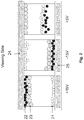
- FIGS. 2, 3 and 4 depict one embodiment of the present invention.
- FIG. 5 depicts an alternative embodiment of the present invention.
- FIGS. 6A and 6B show two options where the display cells are aligned or unaligned, respectively, with the pixel electrodes.
- FIGS. 7A-7E show how a full color display of the present invention is realized.
- FIG. 8 shows an example of shaking waveform.
- the electrophoretic fluid ( 10 ) of present invention comprises three types of pigment particles dispersed in a dielectric solvent or solvent mixture ( 10 a ).
- the three types of pigment particles may be referred to as white particles ( 11 ), black particles ( 12 ) and colored particles ( 13 ), as shown in FIG. 1 .
- the scope of the invention broadly encompasses particles of any colors as long as the three types of particles have visually distinguishable colors.
- a display layer utilizing the display fluid of the present invention has two surfaces, a first surface ( 16 ) on the viewing side and a second surface ( 17 ) on the opposite side of the first surface ( 16 ).
- the display fluid is sandwiched between the two surfaces.
- a common electrode ( 14 ) which is a transparent electrode layer (e.g., ITO), spreading over the entire top of the display layer.
- an electrode layer ( 15 ) which comprises a plurality of pixel electrodes ( 15 a ).
- the display fluid is filled in display cells.
- the display cells may be aligned with or not aligned with the pixel electrodes, as explained below.
- An area corresponding to a pixel electrode may be referred to as a pixel or a sub-pixel.
- the driving of an area corresponding to a pixel electrode is effected by applying a voltage potential difference (or known as an electric field) between the common electrode and the pixel electrode.
- the pixel electrodes are described in U.S. Pat. No. 7,046,228, the content of which is incorporated herein by reference in its entirety. It is noted that while active matrix driving with a thin film transistor (TFT) backplane is mentioned for the layer of pixel electrodes, the scope of the present invention encompasses other types of electrode addressing as long as the electrodes serve the desired functions.
- TFT thin film transistor
- the white particles ( 11 ) may be formed from an inorganic pigment, such as TiO 2 , ZrO 2 , ZnO, Al 2 O 3 , Sb 2 O 3 , BaSO 4 , PbSO 4 or the like.
- an inorganic pigment such as TiO 2 , ZrO 2 , ZnO, Al 2 O 3 , Sb 2 O 3 , BaSO 4 , PbSO 4 or the like.
- black particles ( 12 ) they may be formed from CI pigment black 26 or 28 or the like (e.g., manganese ferrite black spinel or copper chromite black spinel) or carbon black.
- the third type of particles may be of a color such as red, green, blue, magenta, cyan or yellow.
- the pigments for this type of particles may include, but are not limited to, CI pigment PR 254, PR122, PR149, PG36, PG58, PG7, PB28, PB15:3, PY138, PY150, PY155 or PY20.
- CI pigment PR 254, PR122, PR149, PG36, PG58, PG7, PB28, PB15:3, PY138, PY150, PY155 or PY20 are commonly used organic pigments described in color index handbook “New Pigment Application Technology” (CMC Publishing Co, Ltd, 1986) and “Printing Ink Technology” (CMC Publishing Co, Ltd, 1984).
- the first, second and third types of particles may have other distinct optical characteristics, such as optical transmission, reflectance, luminescence or, in the case of displays intended for machine reading, pseudo-color in the sense of a change in reflectance of electromagnetic wavelengths outside the visible range.
- the percentages of the three types of pigment particles in the fluid may vary.
- the black particle may take up about 0.1% to 10%, preferably 0.5% to 5% by volume of the electrophoretic fluid;
- the white particle may take up about 1% to 50%, preferably 5% to 15% by volume of the fluid;
- the colored particle may take up about 2% to 20%, preferably 4% to 10% by volume of the fluid.
- particulate matters in the fluid which are included as additives to enhance performance of the display device, such as switching speed, imaging bistability and reliability.
- the solvent in which the three types of pigment particles are dispersed is clear and colorless. It preferably has a low viscosity and a dielectric constant in the range of about 2 to about 30, preferably about 2 to about 15 for high particle mobility.
- suitable dielectric solvent include hydrocarbons such as isopar, decahydronaphthalene (DECALIN), 5-ethylidene-2-norbornene, fatty oils, paraffin oil, silicon fluids, aromatic hydrocarbons such as toluene, xylene, phenylxylylethane, dodecylbenzene or alkylnaphthalene, halogenated solvents such as perfluorodecalin, perfluorotoluene, perfluoroxylene, dichlorobenzotrifluoride, 3,4,5-trichlorobenzotri fluoride, chloropentafluoro-benzene, dichlorononane or pentachlorobenzene, and perfluorinated solvents such as
- halogen containing polymers such as poly(perfluoropropylene oxide) from TCI America, Portland, Oreg., poly(chlorotrifluoro-ethylene) such as Halocarbon Oils from Halocarbon Product Corp., River Edge, N.J., perfluoropolyalkylether such as Galden from Ausimont or Krytox Oils and Greases K-Fluid Series from DuPont, Del., polydimethylsiloxane based silicone oil from Dow-corning (DC-200).
- poly(perfluoropropylene oxide) from TCI America, Portland, Oreg., poly(chlorotrifluoro-ethylene) such as Halocarbon Oils from Halocarbon Product Corp., River Edge, N.J.
- perfluoropolyalkylether such as Galden from Ausimont or Krytox Oils and Greases K-Fluid Series from DuPont, Del., polydimethylsiloxane based silicone oil from Dow-corn
- the term “slightly charged” is intended to refer to the charge level of the particles less than about 50%, preferably about 5% to about 30%, of the charge intensity of the stronger charged particles.
- the charge intensity may be measured in terms of zeta potential.
- the zeta potential is determined by Colloidal Dynamics AcoustoSizer IIM with a CSPU-100 signal processing unit, ESA EN# Attn flow through cell (K:127).
- the instrument constants such as density of the solvent used in the sample, dielectric constant of the solvent, speed of sound in the solvent, viscosity of the solvent, all of which at the testing temperature (25° C.) are entered before testing.
- Pigment samples are dispersed in the solvent (which is usually a hydrocarbon fluid having less than 12 carbon atoms), and diluted to between 5-10% by weight.
- the sample also contains a charge control agent (Solsperse 17000®, available from Lubrizol Corporation, a Berkshire Hathaway company; “Solsperse” is a Registered Trade Mark), with a weight ratio of 1:10 of the charge control agent to the particles.
- Solsperse 17000® available from Lubrizol Corporation, a Berkshire Hathaway company; “Solsperse” is a Registered Trade Mark
- the mass of the diluted sample is determined and the sample is then loaded into the flow through cell for determination of the zeta potential.
- the colored pigment particles may be slightly charged. In other words, in this example, the charges carried by the black and the white particles are much more intense than the charge carried by the colored particles.
- the third type of particles which carries a slight charge has a charge polarity which is the same as the charge polarity carried by either one of the other two types of the stronger charged particles.
- the three types of particles may have varying sizes.
- one of the three types of particles is larger than the other two types.
- the one type of particles which is slightly charged preferably has the larger size.
- both the black and the white particles are relatively small and their sizes (tested through dynamic light scattering) may range from about 50 nm to about 800 nm and more preferably from about 200 nm to about 700 nm, and in this example, the colored particles which are slightly charged, preferably are about 2 to about 50 times and more preferably about 2 to about 10 times larger than the black particles and the white particles.
- threshold voltage or “electric field threshold”, in the context of the present invention, is defined as the maximum electric field that may be applied for a period of time (typically not longer than 30 seconds, preferably not longer than 15 seconds), to a group of particles, without causing the particles to appear at the viewing side of a pixel, when the pixel is driven from a color state different from the color state of the group of particles.
- viewing side in the present application, refers to the first surface in a display layer where images are seen by the viewers.
- the threshold voltage or electric field threshold is either an inherent characteristic of the charged particles or an additive-induced property.
- the threshold voltage or electric field threshold is generated, relying on certain attraction force between oppositely charged particles or between particles and certain substrate surfaces.
- a threshold agent which induces or enhances the threshold characteristics of an electrophoretic fluid may be added.
- the threshold agent may be any material which is soluble or dispersible in the solvent or solvent mixture of the electrophoretic fluid and carries or induces a charge opposite to that of the charged particles.
- the threshold agent may be sensitive or insensitive to the change of applied voltage.
- the term “threshold agent” may broadly include dyes or pigments, electrolytes or polyelectrolytes, polymers, oligomers, surfactants, charge controlling agents and the like.
- the black particles ( 22 ) are assumed to have a threshold voltage of 5V. Therefore, the black particles ( 22 ) would not move to the viewing side if an applied voltage potential difference is 5V or lower.
- the white particles ( 21 ) are negatively charged while the black particles ( 22 ) are positively charged, and both types of the particles are smaller than the colored particles ( 23 ).
- the colored particles ( 23 ) carry the same charge polarity as the black particles which have the threshold voltage, but are slightly charged. As a result, the black particles move faster than the colored particles ( 23 ), when an applied voltage potential is higher than the threshold voltage of the black particles because of the stronger charge intensity they carry.
- the applied voltage potential difference is +15V.
- the white particles ( 21 ) move to be near or at the pixel electrode ( 25 ) and the black particles ( 22 ) and the colored particles ( 23 ) move to be near or at the common electrode ( 24 ).
- the black color is seen at the viewing side.
- the colored particles ( 23 ) move towards the common electrode ( 24 ); however because their lower charge intensity and larger size, they move slower than the black particles.
- the colored particles ( 23 ) move towards the pixel electrode because they are also positively charged. However, because of their lower charge intensity and larger size, they move slower than the black particles.
- the applied voltage potential difference has changed to +5V.
- the negatively charged white particles ( 21 ) move towards the pixel electrode ( 25 ).
- the black particles ( 22 ) move little because of their threshold voltage being 5V. Due to the fact that the colored particles ( 23 ) do not have a significant threshold voltage, they move to be near or at the common electrode ( 24 ) and as a result, the color of the colored particles is seen at the viewing side.
- the driving from the white color state in the center cell of FIG. 2 to the colored state in the rightmost cell of FIG. 2 may be summarized as follows:
- a driving method for an electrophoretic display comprising display cells filled with an electrophoretic fluid sandwiched between a common electrode and a layer of pixel electrodes, which fluid comprises a first type of pigment particles, a second type of pigment particles and a third type of pigment particles, all of which are dispersed in a solvent or solvent mixture, wherein:
- the first type of pigment particles ( 21 ) is of the white color
- the second type of pigment particles ( 22 ) is of the black color
- the third type of pigment particles ( 23 ) is of the red color, as shown in FIG. 2 .
- the method starts from the color state of the first type of pigment particles, i.e., white (see the center cell of FIG. 2 ).
- the first type of pigment particles i.e., white
- the second and third types of pigment particles i.e., black and red
- the first type of pigment particles i.e., white
- the third type of pigment particles i.e., red
- the second type of pigment particles barely move because of their threshold voltage.
- the other two types of the particles may be mixed at the non-viewing side (side opposite of the viewing side), resulting in an intermediate color state between colors of the first and second types of particles. If the first and second types of particles are black and white and the third type of particles is red, then in the rightmost cell of FIG. 2 , when the red color is seen at the viewing side, a grey color is seen at the non-viewing side.
- the driving method ideally would ensure both color brightness (i.e., preventing the black particles from being seen) and color purity (i.e., preventing the white particles from being seen) in the scenario of the rightmost cell of FIG. 2 .
- this desired result is difficult to control for various reasons, including particle size distribution, particle charge distributions and other factors.
- the shaking waveform consists of repeating a pair of opposite driving pulses for many cycles.
- the shaking waveform may consist of a +15V pulse for 20 msec and a ⁇ 15V pulse for 20 msec and such a pair of pulses is repeated for 50 times.
- the total time of such a shaking waveform would be 2000 msec (see FIG. 8 ).
- the shaking waveform may be applied to an area corresponding to a pixel electrode regardless of its optical state (black, white or red) prior to a driving voltage is applied. After the shaking waveform is applied, the optical state would not be a pure white, pure black or pure red. Instead, the color state would be from a mixture of the three types of particles.
- a shaking waveform is applied to an area corresponding to a pixel electrode prior to the area being driven to the color state (i.e., white) of the first type of pigment particles.
- the color state (i.e., red) of the third type of pigment particles would be significantly better than that without the shaking waveform, on both color brightness and color purity. This is an indication of better separation of the white particles from the red particles as well as the black particles from the red particles.
- Each of the driving pulse in the shaking waveform is applied for not exceeding half of the driving time required from the full black state to the full white state. For example, if it takes 300 msec to drive an area corresponding to a pixel electrode from a full black state to a full white state or vice versa, the shaking waveform may consist of positive and negative pulses, each applied for not more than 150 msec. In practice, it is preferred that the pulses are shorter.
- the white particles ( 31 ) are assumed to have a threshold voltage of 5V. Therefore, the white particles ( 31 ) would not move to the viewing side if an applied voltage potential difference is 5V or lower.
- the white pigment particles ( 31 ) are negatively charged while the black pigment particles ( 32 ) are positively charged, and both types of the pigment particles are smaller than the colored particles ( 33 ).
- the colored particles ( 33 ) carry the same charge polarity as the white particles which have the threshold voltage, but are slightly charged. As a result, the white particles move faster than the colored particles ( 33 ), when an applied voltage potential is higher than the threshold voltage of the white particles because of the stronger charge intensity they carry.
- the applied voltage potential difference is ⁇ 15V.
- the black particles ( 32 ) move to be near or at the pixel electrode ( 35 ) and the white particles ( 31 ) and the colored particles ( 33 ) move to be near or at the common electrode ( 34 ).
- the white color is seen at the viewing side.
- the colored particles ( 33 ) move towards the common electrode ( 34 ); however because of their lower charge intensity and larger size, they move slower than the white particles.
- the colored particles ( 33 ) move towards the pixel electrode as they are also negatively charged. However, because of their lower charge intensity and larger size, they move slower than the white particles.
- the applied voltage potential difference has changed to ⁇ 5V.
- the positively charged black particles ( 32 ) move towards the pixel electrode ( 35 ).
- the white particles ( 32 ) move little because of their threshold voltage being 5V. Due to the fact that the colored particles ( 33 ) do not have a significant threshold voltage, they move to be near or at the common electrode ( 34 ) and as a result, the color of the colored particles is seen at the viewing side.
- the driving of FIG. 3 may be carried out according to the method as described in Example 1(a).
- the colored particles it is also possible to have the colored particles to have a threshold voltage, as shown in FIG. 4 . In this case, the colored particles ( 43 ) would not move to the viewing side if an applied voltage potential difference is 5V or lower.
- the black pigment particles ( 42 ) are negatively charged while the colored pigment particles ( 43 ) are positively charged, and both types of the pigment particles are smaller than the white particles ( 41 ).
- the white particles ( 41 ) carry the same charge polarity as the colored particles which have the threshold voltage, but are slightly charged. As a result, the colored particles move faster than the white particles ( 41 ), when an applied voltage potential difference is higher than the threshold voltage of the colored particles because of the stronger charge intensity they carry.
- the applied voltage potential is +15V.
- the black particles ( 42 ) move to be near or at the pixel electrode ( 45 ) and the colored particles ( 43 ) and the white particles ( 41 ) move to be near or at the common electrode ( 44 ).
- the color of the colored particles is seen at the viewing side.
- the white particles ( 41 ) move towards the common electrode ( 44 ); however because of their lower charge intensity and larger size, they move slower than the colored particles.
- the white particles ( 41 ) move towards the pixel electrode as they are also positively charged. However, because of their lower charge intensity and larger size, they move slower than the colored particles.
- the applied voltage potential difference has changed to +5V.
- the negatively charged black particles ( 42 ) move towards the pixel electrode ( 45 ).
- the colored particles ( 43 ) move little because of their threshold voltage being 5V. Due to the fact that the white particles ( 41 ) do not have a significant threshold voltage, they move to be near or at the common electrode ( 44 ) and as a result, the white color is seen at the viewing side.
- the driving of FIG. 4 may be carried out according to the method as described in Example 1(a).
- all three types of pigment particles have different levels of charge intensity, thus different levels of mobility.
- the first and second types of particles carry opposite charge polarities and the charge intensity of first type of particles is at least about 2 times, preferably about 3 to about 15 times, the charge intensity of the second type of particles, or vice versa.
- the charge intensity of the third type of particles is less than about 50%, preferably about 5% to about 30%, the charge intensity of the first or second type of particles, whichever has a lower charge intensity.
- black particles have twice the charge intensity of the white particles
- the colored particles may have less than 50% the charge intensity of the white particles.
- the particles that carry the least charge intensity are preferably larger than the other two types of particles.
- This example is shown in FIG. 5 . It is assumed that the charge intensity of the black particles ( 52 ) is twice the charge intensity of the white particles ( 51 ) and therefore the black particles move twice as fast as the white particles.
- the colored particles ( 53 ) have a charge intensity which is less than 50% the charge intensity of the white particles.
- the black particles are positively charged and the white particles are negatively charged.
- the colored particles carry the same charge polarity as the particles having the highest intensity, that is, the black particles in this case.
- the white pigment particles ( 51 ) would be near or at the common electrode (i.e., the viewing side) and the black pigment particles ( 52 ) would be near or at the pixel electrode.
- the colored particles ( 53 ) due to their larger size and lower charge intensity/lower mobility, they would move a little. In addition, because they are positively charged, they would move towards the pixel electrode ( 55 ).
- the colored particles barely move. While the black and colored particles carry the same charge polarity, the black particles would move to be closer to the common electrode because of their higher charge intensity and smaller size.
- the white particles are at or near the pixel electrode ( 55 ) and the black and colored particles are at or near the common electrode ( 54 ).
- the white particles ( 51 ) at the bottom would move to an area between the common electrode and the pixel electrode, about at the mid-level, while the black particles ( 52 ) would travel the full distance, d, to be at or near the pixel electrode.
- the colored particles would travel a short distance downward; but remain closer to the common electrode. As a result, the color of the colored particles ( 53 ) is seen at the viewing side.
- the switching among three optical states therefore could be achieved by controlling the driving time frame, driving amplitude or both.
- the larger and slower moving particles in this example are the colored particles. However, the designs may vary depending on the needs. It is also possible to make the black or white particles the larger and slower moving particles.
- the electrophoretic fluid in an electrophoretic display device is filled in display cells.
- the display cells may be microcups as described in U.S. Pat. No. 6,930,818, the content of which is incorporated herein by reference in its entirety.
- the display cells may also be other types of micro-containers, such as microcapsules, microchannels or equivalents, regardless of their shapes or sizes. All of these are within the scope of the present application.
- the display device utilizing the present electrophoretic fluid is a high-light display device and in this embodiment, the colored particles are of the same color in all display cells.
- Each display cell would be a pixel in such a highlight display device if the display cells are aligned with the pixel electrodes.
- the display cells may be aligned with the pixel electrodes (see FIG. 6A ) or unaligned with the pixel electrodes (see FIG. 6B ), in a highlight display device.
- the display device utilizing the present electrophoretic fluid may be a multi-color display device.
- the colored particles are of different colors in the display cells.
- the display cells and the pixel electrodes are aligned.
- FIGS. 7A-7E illustrates how multiple colors are displayed with a display device of the present invention.
- Each sub-pixel corresponds to a pixel electrode and each pixel has three sub-pixels.
- FIG. 7A when a white pixel is desired, all three sub-pixels are turned to the white color state.
- FIG. 7B when a black pixel is desired, all three sub-pixels are turned to the black color state.
- FIG. 7C when a red color is desired, one of the sub-pixels is turned to red and the remaining two sub-pixels are turned to the black state for maximum color saturation.
- FIG. 7D and FIG. 7E display the green and blue colors respectively.
- FIGS. 7C, 7D and 7E one of the sub-pixels is driven to the color state while the remaining two sub-pixels are driven to the white state for maximum brightness (at the expense of the color saturation).
- FIGS. 7C, 7D and 7E one of the sub-pixel is driven to the color state while the remaining two sub-pixels are driven to the black and white states, respectively.
Abstract
Description
-
- (a) the first type of pigment particles and the second type of pigment particles carry opposite charge polarities;
- (b) the third type of pigment particles is slightly charged; and
- (c) the three types of pigment particles have different levels of threshold voltage, or different levels of mobility, or both.
-
- (a) the first type of pigment particles and the second type of pigment particles carry opposite charge polarities;
- (b) the third type of pigment particles has the same charge polarity as the second type of pigment particles, but has an intensity lower than that of the second type of pigment particles; and
- (c) the second type of pigment particles has a threshold voltage, which method comprises driving an area corresponding to a pixel electrode from a color state of the first type of pigment particles to a color state of the third type of pigment particles by applying a voltage potential difference between the common electrode and the pixel electrode, which voltage potential difference is the same as, or lower than, the threshold voltage of the second type of pigment particles.
-
- (a) application of an electric field between the common electrode and a pixel electrode, which electric field is greater than the electric field threshold and having the same polarity as the second type of particles causes an area corresponding to the pixel electrode to display the second optical characteristic at the first surface;
- (b) application of an electric field between the common electrode and a pixel electrode, which electric field is greater than the electric field threshold and having the same polarity as the first type of particles causes an area corresponding to the pixel electrode to display the first optical characteristic at the first surface; or
- (c) once the first optical characteristic is displayed at the first surface, application of an electric field between the common electrode and a pixel electrode, which electric field is the same as, or lower than, the electric field threshold and having the same polarity as the third type of particles causes an area corresponding to the pixel electrode to display the third optical characteristic at the first surface.
-
- (a) applying an electric field between the common electrode and a pixel electrode, which electric field is greater than the electric field threshold and having the same polarity as the second type of particles to cause an area corresponding to the pixel electrode to display the second optical characteristic at the first surface;
- (b) applying an electric field between the common electrode and a pixel electrode, which electric field is greater than the electric field threshold and having the same polarity as the first type of particles to cause an area corresponding to the pixel electrode to display the first optical characteristic at the first surface; or
- (c) once the first optical characteristic is displayed at the first surface, applying an electric field between the common electrode and a pixel electrode, which pixel electrode is the same as, or lower than, the electric field threshold and having the same polarity as the third type of particles to cause an area corresponding to the pixel electrode to display the third optical characteristic at the first surface.
-
- (a) the first type of pigment particles and the second type of pigment particles carry opposite charge polarities;
- (b) the third type of pigment particles has the same charge polarity as the second type of pigment particles, but at a lower intensity; and
- (c) the second type of pigment particles has a threshold voltage, which method comprises driving an area corresponding to a pixel electrode from a color state of the first type of pigment particles to a color state of the third type of pigment particles by applying a voltage potential difference between the common electrode and the pixel electrode, which voltage potential difference is the same as, or lower than, the threshold voltage of the second type of pigment particles.
Claims (13)
Priority Applications (1)
| Application Number | Priority Date | Filing Date | Title |
|---|---|---|---|
| US16/412,684 US11017705B2 (en) | 2012-10-02 | 2019-05-15 | Color display device including multiple pixels for driving three-particle electrophoretic media |
Applications Claiming Priority (5)
| Application Number | Priority Date | Filing Date | Title |
|---|---|---|---|
| US13/633,788 US8717664B2 (en) | 2012-10-02 | 2012-10-02 | Color display device |
| US13/875,145 US8964282B2 (en) | 2012-10-02 | 2013-05-01 | Color display device |
| US14/458,185 US9360733B2 (en) | 2012-10-02 | 2014-08-12 | Color display device |
| US15/153,190 US10332435B2 (en) | 2012-10-02 | 2016-05-12 | Color display device |
| US16/412,684 US11017705B2 (en) | 2012-10-02 | 2019-05-15 | Color display device including multiple pixels for driving three-particle electrophoretic media |
Related Parent Applications (1)
| Application Number | Title | Priority Date | Filing Date |
|---|---|---|---|
| US15/153,190 Continuation US10332435B2 (en) | 2012-10-02 | 2016-05-12 | Color display device |
Publications (2)
| Publication Number | Publication Date |
|---|---|
| US20190333436A1 US20190333436A1 (en) | 2019-10-31 |
| US11017705B2 true US11017705B2 (en) | 2021-05-25 |
Family
ID=68292474
Family Applications (1)
| Application Number | Title | Priority Date | Filing Date |
|---|---|---|---|
| US16/412,684 Active 2033-03-11 US11017705B2 (en) | 2012-10-02 | 2019-05-15 | Color display device including multiple pixels for driving three-particle electrophoretic media |
Country Status (1)
| Country | Link |
|---|---|
| US (1) | US11017705B2 (en) |
Families Citing this family (1)
| Publication number | Priority date | Publication date | Assignee | Title |
|---|---|---|---|---|
| CN110780505B (en) * | 2019-11-13 | 2023-01-20 | 京东方科技集团股份有限公司 | Electronic paper display device and driving method thereof |
Citations (147)
| Publication number | Priority date | Publication date | Assignee | Title |
|---|---|---|---|---|
| US3756693A (en) | 1970-12-21 | 1973-09-04 | Matsushita Electric Ind Co Ltd | Electrophoretic display device |
| WO1999053373A1 (en) | 1998-04-10 | 1999-10-21 | E-Ink Corporation | Full color reflective display with multichromatic sub-pixels |
| JP2000322007A (en) | 1999-05-14 | 2000-11-24 | Brother Ind Ltd | Record medium and electrophoretic display device |
| US6337761B1 (en) | 1999-10-01 | 2002-01-08 | Lucent Technologies Inc. | Electrophoretic display and method of making the same |
| US6517618B2 (en) | 2001-05-24 | 2003-02-11 | Xerox Corporation | Photochromic electrophoretic ink display |
| US6600534B1 (en) | 1997-12-24 | 2003-07-29 | Sharp Kabushiki Kaisha | Reflective liquid crystal display device |
| US6680726B2 (en) | 2001-05-18 | 2004-01-20 | International Business Machines Corporation | Transmissive electrophoretic display with stacked color cells |
| US6729718B2 (en) | 2001-05-09 | 2004-05-04 | Canon Kabushiki Kaisha | Recording method, recording apparatus, method for manufacturing recorded article, and recorded article |
| US6751007B2 (en) | 2001-08-20 | 2004-06-15 | Sipix Imaging, Inc. | Transflective electrophoretic display |
| US6781745B2 (en) | 2001-09-12 | 2004-08-24 | Sipix Imaging, Inc. | Electrophoretic display with gating electrodes |
| US6859302B2 (en) | 2000-03-03 | 2005-02-22 | Sipix Imaging, Inc. | Electrophoretic display and novel process for its manufacture |
| US6864875B2 (en) | 1998-04-10 | 2005-03-08 | E Ink Corporation | Full color reflective display with multichromatic sub-pixels |
| US6870661B2 (en) | 2001-05-15 | 2005-03-22 | E Ink Corporation | Electrophoretic displays containing magnetic particles |
| US6967762B2 (en) | 2003-06-12 | 2005-11-22 | Fuji Xerox Co., Ltd. | Image display medium, image display, device and image display method |
| US6987503B2 (en) | 2000-08-31 | 2006-01-17 | Seiko Epson Corporation | Electrophoretic display |
| US7019889B2 (en) | 2000-06-22 | 2006-03-28 | Seiko Epson Corporation | Method and circuit for driving electrophoretic display and electronic device using same |
| US7034987B2 (en) | 2002-02-19 | 2006-04-25 | Koninklijke Philips Electronics N.V. | Electrophoretic display device |
| US7038656B2 (en) | 2002-08-16 | 2006-05-02 | Sipix Imaging, Inc. | Electrophoretic display with dual-mode switching |
| US7038670B2 (en) | 2002-08-16 | 2006-05-02 | Sipix Imaging, Inc. | Electrophoretic display with dual mode switching |
| US7038655B2 (en) | 1999-05-03 | 2006-05-02 | E Ink Corporation | Electrophoretic ink composed of particles with field dependent mobilities |
| US7046228B2 (en) | 2001-08-17 | 2006-05-16 | Sipix Imaging, Inc. | Electrophoretic display with dual mode switching |
| US7057600B2 (en) | 2000-04-13 | 2006-06-06 | Canon Kabushiki Kaisha | Electrophoretic display method and device |
| JP2006343458A (en) | 2005-06-08 | 2006-12-21 | Casio Comput Co Ltd | Display device |
| US20070002008A1 (en) | 2005-07-04 | 2007-01-04 | Seiko Epson Corporation | Electro-optical arrangement |
| US20070080926A1 (en) | 2003-11-21 | 2007-04-12 | Koninklijke Philips Electronics N.V. | Method and apparatus for driving an electrophoretic display device with reduced image retention |
| US20070080928A1 (en) | 2005-10-12 | 2007-04-12 | Seiko Epson Corporation | Display control apparatus, display device, and control method for a display device |
| JP2007140129A (en) | 2005-11-18 | 2007-06-07 | Bridgestone Corp | Panel for information display |
| US7259744B2 (en) | 1995-07-20 | 2007-08-21 | E Ink Corporation | Dielectrophoretic displays |
| KR20070082680A (en) | 2006-02-17 | 2007-08-22 | 엘지.필립스 엘시디 주식회사 | Electrophoretic display device |
| US7271947B2 (en) | 2002-08-16 | 2007-09-18 | Sipix Imaging, Inc. | Electrophoretic display with dual-mode switching |
| US7283119B2 (en) | 2002-06-14 | 2007-10-16 | Canon Kabushiki Kaisha | Color electrophoretic display device |
| US7292386B2 (en) | 2002-08-22 | 2007-11-06 | Seiko Epson Corporation | Electrophoretic apparatus and electronic equipment |
| US20070273637A1 (en) | 2004-03-22 | 2007-11-29 | Koninklijke Philips Electronics, N.V. | Rail-Stabilized Driving Scheme With Image Memory For An Electrophoretic Display |
| JP2007322617A (en) | 2006-05-31 | 2007-12-13 | Bridgestone Corp | Information display device |
| US7312916B2 (en) | 2002-08-07 | 2007-12-25 | E Ink Corporation | Electrophoretic media containing specularly reflective particles |
| JP2008033000A (en) | 2006-07-28 | 2008-02-14 | Hitachi Metals Ltd | Image display method and image display medium |
| US20080042928A1 (en) | 2004-08-10 | 2008-02-21 | Koninklijke Philips Electronics, N.V. | Electrophoretic Display Panel |
| US7342556B2 (en) | 2002-11-28 | 2008-03-11 | Matsushita Electric Industrial Co., Ltd. | Display device and method of manufacturing same |
| US20080062159A1 (en) | 2006-09-12 | 2008-03-13 | Samsung Electronics Co., Ltd. | Electrophoretic display and method for driving thereof |
| US7345810B2 (en) | 2006-05-19 | 2008-03-18 | Xerox Corporation | Electrophoretic display and method of displaying images |
| US7352353B2 (en) | 1995-07-20 | 2008-04-01 | E Ink Corporation | Electrostatically addressable electrophoretic display |
| KR20080034533A (en) | 2006-10-17 | 2008-04-22 | 엘지전자 주식회사 | Driving method for electronic paper display panel and electronic paper display panel of using method therof |
| US7382521B2 (en) | 2006-05-19 | 2008-06-03 | Xerox Corporation | Electrophoretic display device |
| US20080174531A1 (en) | 2007-01-22 | 2008-07-24 | Wen-Jyh Sah | E-paper apparatus and manufacturing method thereof |
| US7417787B2 (en) | 2006-05-19 | 2008-08-26 | Xerox Corporation | Electrophoretic display device |
| US7420549B2 (en) | 2003-10-08 | 2008-09-02 | E Ink Corporation | Electro-wetting displays |
| JP2008209589A (en) | 2007-02-26 | 2008-09-11 | Hitachi Metals Ltd | Image display method, image display medium and image display device |
| US7433113B2 (en) | 2006-05-19 | 2008-10-07 | Xerox Corporation | Electrophoretic display medium and device |
| US7474295B2 (en) | 2004-01-27 | 2009-01-06 | Canon Kabushiki Kaisha | Display apparatus and driving method thereof |
| US7492505B2 (en) | 2001-08-17 | 2009-02-17 | Sipix Imaging, Inc. | Electrophoretic display with dual mode switching |
| JP2009116041A (en) | 2007-11-06 | 2009-05-28 | Seiko Epson Corp | Electrophoretic display sheet, electrophoretic display device and electronic equipment |
| US7548291B2 (en) | 2003-11-12 | 2009-06-16 | Lg Display Lcd Co., Ltd. | Reflective type liquid crystal display device and fabrication method thereof |
| US7557981B2 (en) | 2000-03-03 | 2009-07-07 | Sipix Imaging, Inc. | Electrophoretic display and process for its manufacture |
| US7572394B2 (en) | 2003-11-04 | 2009-08-11 | Sipix Imaging, Inc. | Electrophoretic dispersions |
| JP2009192637A (en) | 2008-02-12 | 2009-08-27 | Seiko Epson Corp | Electrophoretic display sheet, electrophoretic display device and electronic apparatus |
| US7609435B2 (en) | 2005-12-06 | 2009-10-27 | Fuji Xerox Co., Ltd. | Display medium, display device, and displaying method |
| US7636076B2 (en) | 2005-09-22 | 2009-12-22 | Au Optronics Corporation | Four-color transflective color liquid crystal display |
| US7652656B2 (en) | 2006-05-19 | 2010-01-26 | Xerox Corporation | Electrophoretic display and method of displaying images |
| US7656576B2 (en) | 2006-11-10 | 2010-02-02 | Fuji Xerox Co., Ltd. | Display medium, display device and display method |
| US7675502B2 (en) | 2006-08-30 | 2010-03-09 | Xerox Corporation | Color electrophoretic display device |
| US7679599B2 (en) | 2005-03-04 | 2010-03-16 | Seiko Epson Corporation | Electrophoretic device, method of driving electrophoretic device, and electronic apparatus |
| US7760419B2 (en) | 2008-10-07 | 2010-07-20 | Lg. Display Co., Ltd. | Electrophoretic display device |
| US7800813B2 (en) | 2002-07-17 | 2010-09-21 | Sipix Imaging, Inc. | Methods and compositions for improved electrophoretic display performance |
| US7808696B2 (en) | 2006-07-31 | 2010-10-05 | Samsung Electronics Co., Ltd. | Electrophoretic display device and fabrication thereof |
| US7821792B2 (en) | 2004-03-16 | 2010-10-26 | Hewlett-Packard Development Company, L.P. | Cell board interconnection architecture |
| US7830592B1 (en) | 2007-11-30 | 2010-11-09 | Sipix Imaging, Inc. | Display devices having micro-reflectors |
| US7848009B2 (en) | 2007-08-10 | 2010-12-07 | Fuji Xerox Co., Ltd. | Image display medium and image display device |
| US7852547B2 (en) | 2005-06-15 | 2010-12-14 | Samsung Electronics Co., Ltd. | Electro-wetting display panel and method of manufacturing the same |
| US7852548B2 (en) | 2008-08-11 | 2010-12-14 | Samsung Electronics Co., Ltd. | Electrophoretic display apparatus |
| US7875307B2 (en) | 2007-05-25 | 2011-01-25 | Xerox Corporation | Method for forming an electronic paper display |
| US20110043543A1 (en) | 2009-08-18 | 2011-02-24 | Hui Chen | Color tuning for electrophoretic display |
| US7911681B2 (en) | 2005-07-29 | 2011-03-22 | Dai Nippon Printing Co., Ltd. | Display device, its manufacturing method, and display medium |
| US7952558B2 (en) | 2006-09-29 | 2011-05-31 | Samsung Electronics Co., Ltd. | Methods for driving electrophoretic display so as to avoid persistent unidirectional current through TFT switches |
| US7982941B2 (en) | 2008-09-02 | 2011-07-19 | Sipix Imaging, Inc. | Color display devices |
| US20110175939A1 (en) | 2010-01-18 | 2011-07-21 | Fuji Xerox Co., Ltd. | Display device |
| JP2011158783A (en) | 2010-02-02 | 2011-08-18 | Panasonic Corp | Display particle, method for producing display particle, and image display medium and image display device using display particle |
| US20110217639A1 (en) | 2010-03-02 | 2011-09-08 | Sprague Robert A | Electrophoretic display fluid |
| KR20110103765A (en) | 2010-03-15 | 2011-09-21 | 한국생산기술연구원 | Rib dielectric layer composition of electronic paper display apparatus and rib dielectric layer manufactured using thereof |
| US8040594B2 (en) | 1997-08-28 | 2011-10-18 | E Ink Corporation | Multi-color electrophoretic displays |
| US8054288B2 (en) | 2006-05-19 | 2011-11-08 | Hitachi, Ltd. | Electrophoresis display device |
| US8067305B2 (en) | 2008-09-03 | 2011-11-29 | Ultratech, Inc. | Electrically conductive structure on a semiconductor substrate formed from printing |
| US8072674B2 (en) | 2008-12-01 | 2011-12-06 | E Ink Holdings Inc. | Electro-phoretic display and fabricating method thereof |
| US8072675B2 (en) | 2008-05-01 | 2011-12-06 | Sipix Imaging, Inc. | Color display devices |
| US8077141B2 (en) | 2002-12-16 | 2011-12-13 | E Ink Corporation | Backplanes for electro-optic displays |
| US8081375B2 (en) | 2007-02-26 | 2011-12-20 | Seiko Epson Corporation | Electrophoretic sheet, electrophoresis apparatus, method for manufacturing an electrophoresis apparatus and electronic device |
| US8115729B2 (en) | 1999-05-03 | 2012-02-14 | E Ink Corporation | Electrophoretic display element with filler particles |
| US8120838B2 (en) | 2010-05-19 | 2012-02-21 | Au Optronics Corporation | Electrophoretic display device |
| US8169690B2 (en) | 2008-02-21 | 2012-05-01 | Sipix Imaging, Inc. | Color display devices |
| US8237892B1 (en) | 2007-11-30 | 2012-08-07 | Sipix Imaging, Inc. | Display device with a brightness enhancement structure |
| US8243013B1 (en) | 2007-05-03 | 2012-08-14 | Sipix Imaging, Inc. | Driving bistable displays |
| US8319724B2 (en) | 2008-12-01 | 2012-11-27 | E Ink Holdings Inc. | Sub-pixel structure and pixel structure of color electrophoretic display |
| US20120299947A1 (en) | 2010-01-22 | 2012-11-29 | Sharp Kabushiki Kaisha | Display device |
| US8395836B2 (en) | 2008-03-11 | 2013-03-12 | Sipix Imaging, Inc. | Luminance enhancement structure for reflective display devices |
| US8422116B2 (en) | 2008-04-03 | 2013-04-16 | Sipix Imaging, Inc. | Color display devices |
| US8441713B2 (en) | 2008-08-20 | 2013-05-14 | Ricoh Company, Ltd. | Electrophoretic liquid and display device using electrophoretic liquid |
| US8477405B2 (en) | 2009-03-06 | 2013-07-02 | Fuji Xerox Co., Ltd. | Particle dispersion for display, display medium and display device |
| US8477404B2 (en) | 2008-09-25 | 2013-07-02 | Fuji Xerox Co., Ltd. | Display medium and display device |
| US8503063B2 (en) | 2008-12-30 | 2013-08-06 | Sipix Imaging, Inc. | Multicolor display architecture using enhanced dark state |
| US8558855B2 (en) | 2008-10-24 | 2013-10-15 | Sipix Imaging, Inc. | Driving methods for electrophoretic displays |
| US8565522B2 (en) | 2010-05-21 | 2013-10-22 | Seiko Epson Corporation | Enhancing color images |
| US8570639B2 (en) | 2009-01-13 | 2013-10-29 | Ricoh Company, Ltd. | Electrophoretic liquid, image display medium, and image display device |
| US8570272B2 (en) | 2009-10-29 | 2013-10-29 | Au Optronics Corporation | Electrophoresis display panel |
| US8576475B2 (en) | 2009-07-08 | 2013-11-05 | E Ink Holdings Inc. | MEMS switch |
| US8574937B2 (en) | 2008-01-24 | 2013-11-05 | Sri International | High efficiency electroluminescent devices and methods for producing the same |
| US8605354B2 (en) | 2011-09-02 | 2013-12-10 | Sipix Imaging, Inc. | Color display devices |
| US8629832B2 (en) | 2009-03-13 | 2014-01-14 | Seiko Epson Corporation | Electrophoretic display device, electronic device, and drive method for an electrophoretic display panel |
| US8649084B2 (en) | 2011-09-02 | 2014-02-11 | Sipix Imaging, Inc. | Color display devices |
| US8670174B2 (en) | 2010-11-30 | 2014-03-11 | Sipix Imaging, Inc. | Electrophoretic display fluid |
| US8674978B2 (en) | 2009-07-30 | 2014-03-18 | Seiko Epson Corporation | Electrophoretic display, electrophoretic display device and electronic apparatus |
| US8681191B2 (en) | 2010-07-08 | 2014-03-25 | Sipix Imaging, Inc. | Three dimensional driving scheme for electrophoretic display devices |
| US8687265B2 (en) | 2010-12-15 | 2014-04-01 | Electronics And Telecommunications Research Institute | Methods of operating a display device |
| US8704756B2 (en) | 2010-05-26 | 2014-04-22 | Sipix Imaging, Inc. | Color display architecture and driving methods |
| US8704754B2 (en) | 2010-06-07 | 2014-04-22 | Fuji Xerox Co., Ltd. | Electrophoretic driving method and display device |
| US8717664B2 (en) | 2012-10-02 | 2014-05-06 | Sipix Imaging, Inc. | Color display device |
| US8717662B2 (en) | 2010-06-29 | 2014-05-06 | Seiko Epson Corporation | Display device and electronic apparatus |
| US8717661B2 (en) | 2005-08-22 | 2014-05-06 | Seiko Epson Corporation | Electrophoresis device and electronic apparatus |
| US8786935B2 (en) | 2011-06-02 | 2014-07-22 | Sipix Imaging, Inc. | Color electrophoretic display |
| US8797258B2 (en) | 2008-12-30 | 2014-08-05 | Sipix Imaging, Inc. | Highlight color display architecture using enhanced dark state |
| US8797636B2 (en) | 2012-07-17 | 2014-08-05 | Sipix Imaging, Inc. | Light-enhancing structure for electrophoretic display |
| US20140340734A1 (en) * | 2013-05-17 | 2014-11-20 | Sipix Imaging, Inc. | Driving methods for color display devices |
| US8902491B2 (en) | 2011-09-23 | 2014-12-02 | E Ink California, Llc | Additive for improving optical performance of an electrophoretic display |
| US20140362213A1 (en) | 2013-06-05 | 2014-12-11 | Vincent Tseng | Residence fall and inactivity monitoring system |
| US8917439B2 (en) | 2012-02-09 | 2014-12-23 | E Ink California, Llc | Shutter mode for color display devices |
| US8963903B2 (en) | 2011-04-07 | 2015-02-24 | Nlt Technologies, Ltd. | Image display device having memory property |
| US8964282B2 (en) | 2012-10-02 | 2015-02-24 | E Ink California, Llc | Color display device |
| US9013783B2 (en) | 2011-06-02 | 2015-04-21 | E Ink California, Llc | Color electrophoretic display |
| US9013516B2 (en) | 2011-02-08 | 2015-04-21 | Nlt Technologies, Ltd. | Image display device having memory property |
| US9052564B2 (en) | 2012-03-21 | 2015-06-09 | E Ink California, Llc | Electrophoretic dispersion |
| US20150234250A1 (en) * | 2014-02-19 | 2015-08-20 | E Ink California, Llc | Color display device |
| US20150268531A1 (en) | 2014-03-18 | 2015-09-24 | Sipix Imaging, Inc. | Color display device |
| US9146439B2 (en) | 2011-01-31 | 2015-09-29 | E Ink California, Llc | Color electrophoretic display |
| US20150301246A1 (en) | 2009-08-18 | 2015-10-22 | E Ink California, Llc | Color tuning for electrophoretic display device |
| US9170468B2 (en) | 2013-05-17 | 2015-10-27 | E Ink California, Llc | Color display device |
| US9176358B2 (en) | 2013-03-18 | 2015-11-03 | Seiko Epson Corporation | Electrooptical device, electronic device, and control method for electrooptical device |
| US20160011484A1 (en) * | 2014-07-09 | 2016-01-14 | E Ink California, Llc | Color display device |
| US20160026062A1 (en) | 2011-01-31 | 2016-01-28 | E Ink California, Llc | Color electrophoretic display |
| US9251736B2 (en) * | 2009-01-30 | 2016-02-02 | E Ink California, Llc | Multiple voltage level driving for electrophoretic displays |
| US20160048054A1 (en) | 2007-06-28 | 2016-02-18 | E Ink Corporation | Processes for the production of electro-optic displays, and color filters for use therein |
| US9285649B2 (en) | 2013-04-18 | 2016-03-15 | E Ink California, Llc | Color display device |
| US9360733B2 (en) | 2012-10-02 | 2016-06-07 | E Ink California, Llc | Color display device |
| US9383623B2 (en) | 2013-05-17 | 2016-07-05 | E Ink California, Llc | Color display device |
| US9459510B2 (en) | 2013-05-17 | 2016-10-04 | E Ink California, Llc | Color display device with color filters |
| US20160293111A1 (en) * | 2015-04-06 | 2016-10-06 | E Ink California, Inc. | Driving methods for color display device |
| US9513527B2 (en) | 2014-01-14 | 2016-12-06 | E Ink California, Llc | Color display device |
| US9759980B2 (en) | 2013-04-18 | 2017-09-12 | Eink California, Llc | Color display device |
| US9812073B2 (en) | 2014-11-17 | 2017-11-07 | E Ink California, Llc | Color display device |
| US10162242B2 (en) | 2013-10-11 | 2018-12-25 | E Ink California, Llc | Color display device |
-
2019
- 2019-05-15 US US16/412,684 patent/US11017705B2/en active Active
Patent Citations (163)
| Publication number | Priority date | Publication date | Assignee | Title |
|---|---|---|---|---|
| US3756693A (en) | 1970-12-21 | 1973-09-04 | Matsushita Electric Ind Co Ltd | Electrophoretic display device |
| US7352353B2 (en) | 1995-07-20 | 2008-04-01 | E Ink Corporation | Electrostatically addressable electrophoretic display |
| US7259744B2 (en) | 1995-07-20 | 2007-08-21 | E Ink Corporation | Dielectrophoretic displays |
| US8040594B2 (en) | 1997-08-28 | 2011-10-18 | E Ink Corporation | Multi-color electrophoretic displays |
| US8441714B2 (en) | 1997-08-28 | 2013-05-14 | E Ink Corporation | Multi-color electrophoretic displays |
| US6600534B1 (en) | 1997-12-24 | 2003-07-29 | Sharp Kabushiki Kaisha | Reflective liquid crystal display device |
| US6864875B2 (en) | 1998-04-10 | 2005-03-08 | E Ink Corporation | Full color reflective display with multichromatic sub-pixels |
| WO1999053373A1 (en) | 1998-04-10 | 1999-10-21 | E-Ink Corporation | Full color reflective display with multichromatic sub-pixels |
| US20130278995A1 (en) | 1998-04-10 | 2013-10-24 | E Ink Corporation | Full color reflective display with multichromatic sub-pixels |
| US7075502B1 (en) | 1998-04-10 | 2006-07-11 | E Ink Corporation | Full color reflective display with multichromatic sub-pixels |
| US8466852B2 (en) | 1998-04-10 | 2013-06-18 | E Ink Corporation | Full color reflective display with multichromatic sub-pixels |
| US8115729B2 (en) | 1999-05-03 | 2012-02-14 | E Ink Corporation | Electrophoretic display element with filler particles |
| US7038655B2 (en) | 1999-05-03 | 2006-05-02 | E Ink Corporation | Electrophoretic ink composed of particles with field dependent mobilities |
| JP2000322007A (en) | 1999-05-14 | 2000-11-24 | Brother Ind Ltd | Record medium and electrophoretic display device |
| US6337761B1 (en) | 1999-10-01 | 2002-01-08 | Lucent Technologies Inc. | Electrophoretic display and method of making the same |
| US6859302B2 (en) | 2000-03-03 | 2005-02-22 | Sipix Imaging, Inc. | Electrophoretic display and novel process for its manufacture |
| US6987605B2 (en) | 2000-03-03 | 2006-01-17 | Sipix Imaging, Inc. | Transflective electrophoretic display |
| US6930818B1 (en) | 2000-03-03 | 2005-08-16 | Sipix Imaging, Inc. | Electrophoretic display and novel process for its manufacture |
| US7557981B2 (en) | 2000-03-03 | 2009-07-07 | Sipix Imaging, Inc. | Electrophoretic display and process for its manufacture |
| US7057600B2 (en) | 2000-04-13 | 2006-06-06 | Canon Kabushiki Kaisha | Electrophoretic display method and device |
| US7019889B2 (en) | 2000-06-22 | 2006-03-28 | Seiko Epson Corporation | Method and circuit for driving electrophoretic display and electronic device using same |
| US6987503B2 (en) | 2000-08-31 | 2006-01-17 | Seiko Epson Corporation | Electrophoretic display |
| US6729718B2 (en) | 2001-05-09 | 2004-05-04 | Canon Kabushiki Kaisha | Recording method, recording apparatus, method for manufacturing recorded article, and recorded article |
| US6870661B2 (en) | 2001-05-15 | 2005-03-22 | E Ink Corporation | Electrophoretic displays containing magnetic particles |
| US6680726B2 (en) | 2001-05-18 | 2004-01-20 | International Business Machines Corporation | Transmissive electrophoretic display with stacked color cells |
| US6517618B2 (en) | 2001-05-24 | 2003-02-11 | Xerox Corporation | Photochromic electrophoretic ink display |
| US7821702B2 (en) | 2001-08-17 | 2010-10-26 | Sipix Imaging, Inc. | Electrophoretic display with dual mode switching |
| US7492505B2 (en) | 2001-08-17 | 2009-02-17 | Sipix Imaging, Inc. | Electrophoretic display with dual mode switching |
| US7046228B2 (en) | 2001-08-17 | 2006-05-16 | Sipix Imaging, Inc. | Electrophoretic display with dual mode switching |
| US7679813B2 (en) | 2001-08-17 | 2010-03-16 | Sipix Imaging, Inc. | Electrophoretic display with dual-mode switching |
| US6751007B2 (en) | 2001-08-20 | 2004-06-15 | Sipix Imaging, Inc. | Transflective electrophoretic display |
| US6781745B2 (en) | 2001-09-12 | 2004-08-24 | Sipix Imaging, Inc. | Electrophoretic display with gating electrodes |
| US7034987B2 (en) | 2002-02-19 | 2006-04-25 | Koninklijke Philips Electronics N.V. | Electrophoretic display device |
| US7283119B2 (en) | 2002-06-14 | 2007-10-16 | Canon Kabushiki Kaisha | Color electrophoretic display device |
| US7800813B2 (en) | 2002-07-17 | 2010-09-21 | Sipix Imaging, Inc. | Methods and compositions for improved electrophoretic display performance |
| US7312916B2 (en) | 2002-08-07 | 2007-12-25 | E Ink Corporation | Electrophoretic media containing specularly reflective particles |
| US7271947B2 (en) | 2002-08-16 | 2007-09-18 | Sipix Imaging, Inc. | Electrophoretic display with dual-mode switching |
| US7038670B2 (en) | 2002-08-16 | 2006-05-02 | Sipix Imaging, Inc. | Electrophoretic display with dual mode switching |
| US7038656B2 (en) | 2002-08-16 | 2006-05-02 | Sipix Imaging, Inc. | Electrophoretic display with dual-mode switching |
| US7292386B2 (en) | 2002-08-22 | 2007-11-06 | Seiko Epson Corporation | Electrophoretic apparatus and electronic equipment |
| US7342556B2 (en) | 2002-11-28 | 2008-03-11 | Matsushita Electric Industrial Co., Ltd. | Display device and method of manufacturing same |
| US8077141B2 (en) | 2002-12-16 | 2011-12-13 | E Ink Corporation | Backplanes for electro-optic displays |
| US6967762B2 (en) | 2003-06-12 | 2005-11-22 | Fuji Xerox Co., Ltd. | Image display medium, image display, device and image display method |
| US7420549B2 (en) | 2003-10-08 | 2008-09-02 | E Ink Corporation | Electro-wetting displays |
| US7572394B2 (en) | 2003-11-04 | 2009-08-11 | Sipix Imaging, Inc. | Electrophoretic dispersions |
| US7548291B2 (en) | 2003-11-12 | 2009-06-16 | Lg Display Lcd Co., Ltd. | Reflective type liquid crystal display device and fabrication method thereof |
| US20070080926A1 (en) | 2003-11-21 | 2007-04-12 | Koninklijke Philips Electronics N.V. | Method and apparatus for driving an electrophoretic display device with reduced image retention |
| US9740076B2 (en) | 2003-12-05 | 2017-08-22 | E Ink Corporation | Multi-color electrophoretic displays |
| US7474295B2 (en) | 2004-01-27 | 2009-01-06 | Canon Kabushiki Kaisha | Display apparatus and driving method thereof |
| US7821792B2 (en) | 2004-03-16 | 2010-10-26 | Hewlett-Packard Development Company, L.P. | Cell board interconnection architecture |
| US20070273637A1 (en) | 2004-03-22 | 2007-11-29 | Koninklijke Philips Electronics, N.V. | Rail-Stabilized Driving Scheme With Image Memory For An Electrophoretic Display |
| US20080042928A1 (en) | 2004-08-10 | 2008-02-21 | Koninklijke Philips Electronics, N.V. | Electrophoretic Display Panel |
| US7679599B2 (en) | 2005-03-04 | 2010-03-16 | Seiko Epson Corporation | Electrophoretic device, method of driving electrophoretic device, and electronic apparatus |
| JP2006343458A (en) | 2005-06-08 | 2006-12-21 | Casio Comput Co Ltd | Display device |
| US7852547B2 (en) | 2005-06-15 | 2010-12-14 | Samsung Electronics Co., Ltd. | Electro-wetting display panel and method of manufacturing the same |
| US20070002008A1 (en) | 2005-07-04 | 2007-01-04 | Seiko Epson Corporation | Electro-optical arrangement |
| US7911681B2 (en) | 2005-07-29 | 2011-03-22 | Dai Nippon Printing Co., Ltd. | Display device, its manufacturing method, and display medium |
| US8164823B2 (en) | 2005-07-29 | 2012-04-24 | Dai Nippon Printing Co., Ltd. | Display system, manufacture method thereof and display medium |
| US8717661B2 (en) | 2005-08-22 | 2014-05-06 | Seiko Epson Corporation | Electrophoresis device and electronic apparatus |
| US7636076B2 (en) | 2005-09-22 | 2009-12-22 | Au Optronics Corporation | Four-color transflective color liquid crystal display |
| US20070080928A1 (en) | 2005-10-12 | 2007-04-12 | Seiko Epson Corporation | Display control apparatus, display device, and control method for a display device |
| JP2007140129A (en) | 2005-11-18 | 2007-06-07 | Bridgestone Corp | Panel for information display |
| US7609435B2 (en) | 2005-12-06 | 2009-10-27 | Fuji Xerox Co., Ltd. | Display medium, display device, and displaying method |
| KR20070082680A (en) | 2006-02-17 | 2007-08-22 | 엘지.필립스 엘시디 주식회사 | Electrophoretic display device |
| US7382521B2 (en) | 2006-05-19 | 2008-06-03 | Xerox Corporation | Electrophoretic display device |
| US7652656B2 (en) | 2006-05-19 | 2010-01-26 | Xerox Corporation | Electrophoretic display and method of displaying images |
| US7345810B2 (en) | 2006-05-19 | 2008-03-18 | Xerox Corporation | Electrophoretic display and method of displaying images |
| US7433113B2 (en) | 2006-05-19 | 2008-10-07 | Xerox Corporation | Electrophoretic display medium and device |
| US8054288B2 (en) | 2006-05-19 | 2011-11-08 | Hitachi, Ltd. | Electrophoresis display device |
| US7417787B2 (en) | 2006-05-19 | 2008-08-26 | Xerox Corporation | Electrophoretic display device |
| JP2007322617A (en) | 2006-05-31 | 2007-12-13 | Bridgestone Corp | Information display device |
| JP2008033000A (en) | 2006-07-28 | 2008-02-14 | Hitachi Metals Ltd | Image display method and image display medium |
| US7808696B2 (en) | 2006-07-31 | 2010-10-05 | Samsung Electronics Co., Ltd. | Electrophoretic display device and fabrication thereof |
| US7675502B2 (en) | 2006-08-30 | 2010-03-09 | Xerox Corporation | Color electrophoretic display device |
| US20080062159A1 (en) | 2006-09-12 | 2008-03-13 | Samsung Electronics Co., Ltd. | Electrophoretic display and method for driving thereof |
| US7952558B2 (en) | 2006-09-29 | 2011-05-31 | Samsung Electronics Co., Ltd. | Methods for driving electrophoretic display so as to avoid persistent unidirectional current through TFT switches |
| KR20080034533A (en) | 2006-10-17 | 2008-04-22 | 엘지전자 주식회사 | Driving method for electronic paper display panel and electronic paper display panel of using method therof |
| US7656576B2 (en) | 2006-11-10 | 2010-02-02 | Fuji Xerox Co., Ltd. | Display medium, display device and display method |
| US20080174531A1 (en) | 2007-01-22 | 2008-07-24 | Wen-Jyh Sah | E-paper apparatus and manufacturing method thereof |
| US8081375B2 (en) | 2007-02-26 | 2011-12-20 | Seiko Epson Corporation | Electrophoretic sheet, electrophoresis apparatus, method for manufacturing an electrophoresis apparatus and electronic device |
| JP2008209589A (en) | 2007-02-26 | 2008-09-11 | Hitachi Metals Ltd | Image display method, image display medium and image display device |
| US8243013B1 (en) | 2007-05-03 | 2012-08-14 | Sipix Imaging, Inc. | Driving bistable displays |
| US7875307B2 (en) | 2007-05-25 | 2011-01-25 | Xerox Corporation | Method for forming an electronic paper display |
| US20160048054A1 (en) | 2007-06-28 | 2016-02-18 | E Ink Corporation | Processes for the production of electro-optic displays, and color filters for use therein |
| US7848009B2 (en) | 2007-08-10 | 2010-12-07 | Fuji Xerox Co., Ltd. | Image display medium and image display device |
| JP2009116041A (en) | 2007-11-06 | 2009-05-28 | Seiko Epson Corp | Electrophoretic display sheet, electrophoretic display device and electronic equipment |
| US8237892B1 (en) | 2007-11-30 | 2012-08-07 | Sipix Imaging, Inc. | Display device with a brightness enhancement structure |
| US7830592B1 (en) | 2007-11-30 | 2010-11-09 | Sipix Imaging, Inc. | Display devices having micro-reflectors |
| US8574937B2 (en) | 2008-01-24 | 2013-11-05 | Sri International | High efficiency electroluminescent devices and methods for producing the same |
| JP2009192637A (en) | 2008-02-12 | 2009-08-27 | Seiko Epson Corp | Electrophoretic display sheet, electrophoretic display device and electronic apparatus |
| US8169690B2 (en) | 2008-02-21 | 2012-05-01 | Sipix Imaging, Inc. | Color display devices |
| US8395836B2 (en) | 2008-03-11 | 2013-03-12 | Sipix Imaging, Inc. | Luminance enhancement structure for reflective display devices |
| US8810899B2 (en) | 2008-04-03 | 2014-08-19 | E Ink California, Llc | Color display devices |
| US8422116B2 (en) | 2008-04-03 | 2013-04-16 | Sipix Imaging, Inc. | Color display devices |
| US8072675B2 (en) | 2008-05-01 | 2011-12-06 | Sipix Imaging, Inc. | Color display devices |
| US7852548B2 (en) | 2008-08-11 | 2010-12-14 | Samsung Electronics Co., Ltd. | Electrophoretic display apparatus |
| US8441713B2 (en) | 2008-08-20 | 2013-05-14 | Ricoh Company, Ltd. | Electrophoretic liquid and display device using electrophoretic liquid |
| US7982941B2 (en) | 2008-09-02 | 2011-07-19 | Sipix Imaging, Inc. | Color display devices |
| US8067305B2 (en) | 2008-09-03 | 2011-11-29 | Ultratech, Inc. | Electrically conductive structure on a semiconductor substrate formed from printing |
| US8477404B2 (en) | 2008-09-25 | 2013-07-02 | Fuji Xerox Co., Ltd. | Display medium and display device |
| US7760419B2 (en) | 2008-10-07 | 2010-07-20 | Lg. Display Co., Ltd. | Electrophoretic display device |
| US8558855B2 (en) | 2008-10-24 | 2013-10-15 | Sipix Imaging, Inc. | Driving methods for electrophoretic displays |
| US8072674B2 (en) | 2008-12-01 | 2011-12-06 | E Ink Holdings Inc. | Electro-phoretic display and fabricating method thereof |
| US8520296B2 (en) | 2008-12-01 | 2013-08-27 | E Ink Holdings Inc. | Sub-pixel structure and pixel structure of color electrophoretic display |
| US8319724B2 (en) | 2008-12-01 | 2012-11-27 | E Ink Holdings Inc. | Sub-pixel structure and pixel structure of color electrophoretic display |
| US8503063B2 (en) | 2008-12-30 | 2013-08-06 | Sipix Imaging, Inc. | Multicolor display architecture using enhanced dark state |
| US8797258B2 (en) | 2008-12-30 | 2014-08-05 | Sipix Imaging, Inc. | Highlight color display architecture using enhanced dark state |
| US8570639B2 (en) | 2009-01-13 | 2013-10-29 | Ricoh Company, Ltd. | Electrophoretic liquid, image display medium, and image display device |
| US9251736B2 (en) * | 2009-01-30 | 2016-02-02 | E Ink California, Llc | Multiple voltage level driving for electrophoretic displays |
| US8477405B2 (en) | 2009-03-06 | 2013-07-02 | Fuji Xerox Co., Ltd. | Particle dispersion for display, display medium and display device |
| US8629832B2 (en) | 2009-03-13 | 2014-01-14 | Seiko Epson Corporation | Electrophoretic display device, electronic device, and drive method for an electrophoretic display panel |
| US8576475B2 (en) | 2009-07-08 | 2013-11-05 | E Ink Holdings Inc. | MEMS switch |
| US8674978B2 (en) | 2009-07-30 | 2014-03-18 | Seiko Epson Corporation | Electrophoretic display, electrophoretic display device and electronic apparatus |
| US20150301246A1 (en) | 2009-08-18 | 2015-10-22 | E Ink California, Llc | Color tuning for electrophoretic display device |
| US20110043543A1 (en) | 2009-08-18 | 2011-02-24 | Hui Chen | Color tuning for electrophoretic display |
| US20140055840A1 (en) | 2009-08-18 | 2014-02-27 | Sipix Imaging, Inc. | Color tuning for electrophoretic display device |
| US8570272B2 (en) | 2009-10-29 | 2013-10-29 | Au Optronics Corporation | Electrophoresis display panel |
| US20110175939A1 (en) | 2010-01-18 | 2011-07-21 | Fuji Xerox Co., Ltd. | Display device |
| US20120299947A1 (en) | 2010-01-22 | 2012-11-29 | Sharp Kabushiki Kaisha | Display device |
| JP2011158783A (en) | 2010-02-02 | 2011-08-18 | Panasonic Corp | Display particle, method for producing display particle, and image display medium and image display device using display particle |
| US20110217639A1 (en) | 2010-03-02 | 2011-09-08 | Sprague Robert A | Electrophoretic display fluid |
| KR20110103765A (en) | 2010-03-15 | 2011-09-21 | 한국생산기술연구원 | Rib dielectric layer composition of electronic paper display apparatus and rib dielectric layer manufactured using thereof |
| US8120838B2 (en) | 2010-05-19 | 2012-02-21 | Au Optronics Corporation | Electrophoretic display device |
| US8565522B2 (en) | 2010-05-21 | 2013-10-22 | Seiko Epson Corporation | Enhancing color images |
| US8704756B2 (en) | 2010-05-26 | 2014-04-22 | Sipix Imaging, Inc. | Color display architecture and driving methods |
| US8704754B2 (en) | 2010-06-07 | 2014-04-22 | Fuji Xerox Co., Ltd. | Electrophoretic driving method and display device |
| US8717662B2 (en) | 2010-06-29 | 2014-05-06 | Seiko Epson Corporation | Display device and electronic apparatus |
| US8681191B2 (en) | 2010-07-08 | 2014-03-25 | Sipix Imaging, Inc. | Three dimensional driving scheme for electrophoretic display devices |
| US8670174B2 (en) | 2010-11-30 | 2014-03-11 | Sipix Imaging, Inc. | Electrophoretic display fluid |
| US8687265B2 (en) | 2010-12-15 | 2014-04-01 | Electronics And Telecommunications Research Institute | Methods of operating a display device |
| US20160026062A1 (en) | 2011-01-31 | 2016-01-28 | E Ink California, Llc | Color electrophoretic display |
| US9146439B2 (en) | 2011-01-31 | 2015-09-29 | E Ink California, Llc | Color electrophoretic display |
| US9013516B2 (en) | 2011-02-08 | 2015-04-21 | Nlt Technologies, Ltd. | Image display device having memory property |
| US8963903B2 (en) | 2011-04-07 | 2015-02-24 | Nlt Technologies, Ltd. | Image display device having memory property |
| US8786935B2 (en) | 2011-06-02 | 2014-07-22 | Sipix Imaging, Inc. | Color electrophoretic display |
| US9013783B2 (en) | 2011-06-02 | 2015-04-21 | E Ink California, Llc | Color electrophoretic display |
| US8605354B2 (en) | 2011-09-02 | 2013-12-10 | Sipix Imaging, Inc. | Color display devices |
| US8649084B2 (en) | 2011-09-02 | 2014-02-11 | Sipix Imaging, Inc. | Color display devices |
| US8902491B2 (en) | 2011-09-23 | 2014-12-02 | E Ink California, Llc | Additive for improving optical performance of an electrophoretic display |
| US8917439B2 (en) | 2012-02-09 | 2014-12-23 | E Ink California, Llc | Shutter mode for color display devices |
| US9052564B2 (en) | 2012-03-21 | 2015-06-09 | E Ink California, Llc | Electrophoretic dispersion |
| US8797636B2 (en) | 2012-07-17 | 2014-08-05 | Sipix Imaging, Inc. | Light-enhancing structure for electrophoretic display |
| US20160260372A1 (en) | 2012-10-02 | 2016-09-08 | E Ink California, Llc | Color display device |
| US9360733B2 (en) | 2012-10-02 | 2016-06-07 | E Ink California, Llc | Color display device |
| US8964282B2 (en) | 2012-10-02 | 2015-02-24 | E Ink California, Llc | Color display device |
| US8717664B2 (en) | 2012-10-02 | 2014-05-06 | Sipix Imaging, Inc. | Color display device |
| US9176358B2 (en) | 2013-03-18 | 2015-11-03 | Seiko Epson Corporation | Electrooptical device, electronic device, and control method for electrooptical device |
| US9285649B2 (en) | 2013-04-18 | 2016-03-15 | E Ink California, Llc | Color display device |
| US9759980B2 (en) | 2013-04-18 | 2017-09-12 | Eink California, Llc | Color display device |
| US9170468B2 (en) | 2013-05-17 | 2015-10-27 | E Ink California, Llc | Color display device |
| US9383623B2 (en) | 2013-05-17 | 2016-07-05 | E Ink California, Llc | Color display device |
| US9459510B2 (en) | 2013-05-17 | 2016-10-04 | E Ink California, Llc | Color display device with color filters |
| US20140340734A1 (en) * | 2013-05-17 | 2014-11-20 | Sipix Imaging, Inc. | Driving methods for color display devices |
| US20140362213A1 (en) | 2013-06-05 | 2014-12-11 | Vincent Tseng | Residence fall and inactivity monitoring system |
| US10162242B2 (en) | 2013-10-11 | 2018-12-25 | E Ink California, Llc | Color display device |
| US9513527B2 (en) | 2014-01-14 | 2016-12-06 | E Ink California, Llc | Color display device |
| US20150234250A1 (en) * | 2014-02-19 | 2015-08-20 | E Ink California, Llc | Color display device |
| US9541814B2 (en) | 2014-02-19 | 2017-01-10 | E Ink California, Llc | Color display device |
| US20150268531A1 (en) | 2014-03-18 | 2015-09-24 | Sipix Imaging, Inc. | Color display device |
| US9671668B2 (en) | 2014-07-09 | 2017-06-06 | E Ink California, Llc | Color display device |
| US20160011484A1 (en) * | 2014-07-09 | 2016-01-14 | E Ink California, Llc | Color display device |
| US9812073B2 (en) | 2014-11-17 | 2017-11-07 | E Ink California, Llc | Color display device |
| US20160293111A1 (en) * | 2015-04-06 | 2016-10-06 | E Ink California, Inc. | Driving methods for color display device |
Non-Patent Citations (3)
| Title |
|---|
| European Patent Office, EP Appl. No. 18020193.1, European Search Report, dated Aug. 6, 2018. Aug. 6, 2018. |
| European Patent Office; EP Appl. No. 13844148.0, European Search Report, dated Apr. 29, 2016. Apr. 29, 2016. |
| Korean Intellectual Property Office, PCT/US2013/062915, International Search Report and Written Opinion, dated Jan. 28, 2014. Jan. 28, 2014. |
Also Published As
| Publication number | Publication date |
|---|---|
| US20190333436A1 (en) | 2019-10-31 |
Similar Documents
| Publication | Publication Date | Title |
|---|---|---|
| US10332435B2 (en) | Color display device | |
| US10901287B2 (en) | Driving methods for color display devices | |
| US10126628B2 (en) | Color display device | |
| US11315504B2 (en) | Driving methods with shaking waveform | |
| US8964282B2 (en) | Color display device | |
| US8717664B2 (en) | Color display device | |
| US9459510B2 (en) | Color display device with color filters | |
| US9285649B2 (en) | Color display device | |
| US20190378465A1 (en) | Electrophoretic display including four particles with different charges and optical characteristics | |
| US11017705B2 (en) | Color display device including multiple pixels for driving three-particle electrophoretic media |
Legal Events
| Date | Code | Title | Description |
|---|---|---|---|
| FEPP | Fee payment procedure |
Free format text: ENTITY STATUS SET TO UNDISCOUNTED (ORIGINAL EVENT CODE: BIG.); ENTITY STATUS OF PATENT OWNER: LARGE ENTITY |
|
| AS | Assignment |
Owner name: E INK CALIFORNIA, LLC, CALIFORNIA Free format text: ASSIGNMENT OF ASSIGNORS INTEREST;ASSIGNORS:WANG, MING;LI, YU;DU, HUI;AND OTHERS;SIGNING DATES FROM 20140828 TO 20140914;REEL/FRAME:049360/0785 |
|
| STPP | Information on status: patent application and granting procedure in general |
Free format text: DOCKETED NEW CASE - READY FOR EXAMINATION |
|
| STPP | Information on status: patent application and granting procedure in general |
Free format text: NON FINAL ACTION MAILED |
|
| STPP | Information on status: patent application and granting procedure in general |
Free format text: RESPONSE TO NON-FINAL OFFICE ACTION ENTERED AND FORWARDED TO EXAMINER |
|
| STPP | Information on status: patent application and granting procedure in general |
Free format text: NOTICE OF ALLOWANCE MAILED -- APPLICATION RECEIVED IN OFFICE OF PUBLICATIONS |
|
| STPP | Information on status: patent application and granting procedure in general |
Free format text: PUBLICATIONS -- ISSUE FEE PAYMENT VERIFIED |
|
| STCF | Information on status: patent grant |
Free format text: PATENTED CASE |
|
| AS | Assignment |
Owner name: E INK CORPORATION, MASSACHUSETTS Free format text: ASSIGNMENT OF ASSIGNORS INTEREST;ASSIGNOR:E INK CALIFORNIA, LLC;REEL/FRAME:065154/0965 Effective date: 20230925 |