US10797399B2 - Wireless power transmission system and communication system - Google Patents
Wireless power transmission system and communication system Download PDFInfo
- Publication number
- US10797399B2 US10797399B2 US16/310,790 US201616310790A US10797399B2 US 10797399 B2 US10797399 B2 US 10797399B2 US 201616310790 A US201616310790 A US 201616310790A US 10797399 B2 US10797399 B2 US 10797399B2
- Authority
- US
- United States
- Prior art keywords
- transmitter
- surface wave
- communication system
- metal wall
- power transmission
- Prior art date
- Legal status (The legal status is an assumption and is not a legal conclusion. Google has not performed a legal analysis and makes no representation as to the accuracy of the status listed.)
- Active, expires
Links
- 230000006854 communication Effects 0.000 title claims abstract description 49
- 230000005540 biological transmission Effects 0.000 title claims abstract description 46
- 239000002184 metal Substances 0.000 claims abstract description 45
- 229910052751 metal Inorganic materials 0.000 claims abstract description 45
- 230000005404 monopole Effects 0.000 claims abstract description 36
- 239000010409 thin film Substances 0.000 claims description 3
- 230000000737 periodic effect Effects 0.000 claims description 2
- 238000010586 diagram Methods 0.000 description 16
- 238000000034 method Methods 0.000 description 6
- 102000046669 Surf-1 Human genes 0.000 description 3
- 230000007175 bidirectional communication Effects 0.000 description 3
- 108010066057 cabin-1 Proteins 0.000 description 3
- 101150081019 surf1 gene Proteins 0.000 description 3
- RYGMFSIKBFXOCR-UHFFFAOYSA-N Copper Chemical compound [Cu] RYGMFSIKBFXOCR-UHFFFAOYSA-N 0.000 description 2
- 102100030638 Surfeit locus protein 2 Human genes 0.000 description 2
- 101710093351 Surfeit locus protein 2 Proteins 0.000 description 2
- 239000004020 conductor Substances 0.000 description 2
- 229910052802 copper Inorganic materials 0.000 description 2
- 239000010949 copper Substances 0.000 description 2
- 239000013078 crystal Substances 0.000 description 2
- 229920000049 Carbon (fiber) Polymers 0.000 description 1
- 108010066114 cabin-2 Proteins 0.000 description 1
- 239000004917 carbon fiber Substances 0.000 description 1
- 230000007423 decrease Effects 0.000 description 1
- 230000003993 interaction Effects 0.000 description 1
- 239000000463 material Substances 0.000 description 1
- VNWKTOKETHGBQD-UHFFFAOYSA-N methane Chemical compound C VNWKTOKETHGBQD-UHFFFAOYSA-N 0.000 description 1
- 238000012986 modification Methods 0.000 description 1
- 230000004048 modification Effects 0.000 description 1
- 229920000515 polycarbonate Polymers 0.000 description 1
- 239000004417 polycarbonate Substances 0.000 description 1
- 239000011800 void material Substances 0.000 description 1
Images


Classifications
-
- H—ELECTRICITY
- H01—ELECTRIC ELEMENTS
- H01Q—ANTENNAS, i.e. RADIO AERIALS
- H01Q1/00—Details of, or arrangements associated with, antennas
- H01Q1/27—Adaptation for use in or on movable bodies
- H01Q1/34—Adaptation for use in or on ships, submarines, buoys or torpedoes
-
- H—ELECTRICITY
- H01—ELECTRIC ELEMENTS
- H01Q—ANTENNAS, i.e. RADIO AERIALS
- H01Q13/00—Waveguide horns or mouths; Slot antennas; Leaky-waveguide antennas; Equivalent structures causing radiation along the transmission path of a guided wave
- H01Q13/20—Non-resonant leaky-waveguide or transmission-line antennas; Equivalent structures causing radiation along the transmission path of a guided wave
- H01Q13/26—Surface waveguide constituted by a single conductor, e.g. strip conductor
-
- H—ELECTRICITY
- H01—ELECTRIC ELEMENTS
- H01Q—ANTENNAS, i.e. RADIO AERIALS
- H01Q13/00—Waveguide horns or mouths; Slot antennas; Leaky-waveguide antennas; Equivalent structures causing radiation along the transmission path of a guided wave
- H01Q13/20—Non-resonant leaky-waveguide or transmission-line antennas; Equivalent structures causing radiation along the transmission path of a guided wave
- H01Q13/28—Non-resonant leaky-waveguide or transmission-line antennas; Equivalent structures causing radiation along the transmission path of a guided wave comprising elements constituting electric discontinuities and spaced in direction of wave propagation, e.g. dielectric elements or conductive elements forming artificial dielectric
-
- H—ELECTRICITY
- H01—ELECTRIC ELEMENTS
- H01Q—ANTENNAS, i.e. RADIO AERIALS
- H01Q21/00—Antenna arrays or systems
- H01Q21/30—Combinations of separate antenna units operating in different wavebands and connected to a common feeder system
-
- H—ELECTRICITY
- H01—ELECTRIC ELEMENTS
- H01Q—ANTENNAS, i.e. RADIO AERIALS
- H01Q9/00—Electrically-short antennas having dimensions not more than twice the operating wavelength and consisting of conductive active radiating elements
- H01Q9/04—Resonant antennas
- H01Q9/30—Resonant antennas with feed to end of elongated active element, e.g. unipole
- H01Q9/32—Vertical arrangement of element
-
- H—ELECTRICITY
- H02—GENERATION; CONVERSION OR DISTRIBUTION OF ELECTRIC POWER
- H02J—CIRCUIT ARRANGEMENTS OR SYSTEMS FOR SUPPLYING OR DISTRIBUTING ELECTRIC POWER; SYSTEMS FOR STORING ELECTRIC ENERGY
- H02J50/00—Circuit arrangements or systems for wireless supply or distribution of electric power
- H02J50/005—Mechanical details of housing or structure aiming to accommodate the power transfer means, e.g. mechanical integration of coils, antennas or transducers into emitting or receiving devices
-
- H—ELECTRICITY
- H02—GENERATION; CONVERSION OR DISTRIBUTION OF ELECTRIC POWER
- H02J—CIRCUIT ARRANGEMENTS OR SYSTEMS FOR SUPPLYING OR DISTRIBUTING ELECTRIC POWER; SYSTEMS FOR STORING ELECTRIC ENERGY
- H02J50/00—Circuit arrangements or systems for wireless supply or distribution of electric power
- H02J50/20—Circuit arrangements or systems for wireless supply or distribution of electric power using microwaves or radio frequency waves
- H02J50/23—Circuit arrangements or systems for wireless supply or distribution of electric power using microwaves or radio frequency waves characterised by the type of transmitting antennas, e.g. directional array antennas or Yagi antennas
-
- H—ELECTRICITY
- H02—GENERATION; CONVERSION OR DISTRIBUTION OF ELECTRIC POWER
- H02J—CIRCUIT ARRANGEMENTS OR SYSTEMS FOR SUPPLYING OR DISTRIBUTING ELECTRIC POWER; SYSTEMS FOR STORING ELECTRIC ENERGY
- H02J50/00—Circuit arrangements or systems for wireless supply or distribution of electric power
- H02J50/20—Circuit arrangements or systems for wireless supply or distribution of electric power using microwaves or radio frequency waves
- H02J50/27—Circuit arrangements or systems for wireless supply or distribution of electric power using microwaves or radio frequency waves characterised by the type of receiving antennas, e.g. rectennas
-
- H—ELECTRICITY
- H02—GENERATION; CONVERSION OR DISTRIBUTION OF ELECTRIC POWER
- H02J—CIRCUIT ARRANGEMENTS OR SYSTEMS FOR SUPPLYING OR DISTRIBUTING ELECTRIC POWER; SYSTEMS FOR STORING ELECTRIC ENERGY
- H02J50/00—Circuit arrangements or systems for wireless supply or distribution of electric power
- H02J50/50—Circuit arrangements or systems for wireless supply or distribution of electric power using additional energy repeaters between transmitting devices and receiving devices
-
- H—ELECTRICITY
- H03—ELECTRONIC CIRCUITRY
- H03H—IMPEDANCE NETWORKS, e.g. RESONANT CIRCUITS; RESONATORS
- H03H7/00—Multiple-port networks comprising only passive electrical elements as network components
- H03H7/38—Impedance-matching networks
-
- H—ELECTRICITY
- H04—ELECTRIC COMMUNICATION TECHNIQUE
- H04B—TRANSMISSION
- H04B5/00—Near-field transmission systems, e.g. inductive or capacitive transmission systems
- H04B5/70—Near-field transmission systems, e.g. inductive or capacitive transmission systems specially adapted for specific purposes
- H04B5/79—Near-field transmission systems, e.g. inductive or capacitive transmission systems specially adapted for specific purposes for data transfer in combination with power transfer
Definitions
- Various methods are used to provide a means for communication to users in remote locations as in, for example, a large ship or vessel, a container, and the like.
- wired communication may be performed using a buried cable that connects cabins in the large ship.
- a method of forming a hole in a metal wall of a cabin and burying a cable through the hole may be used to build an environment for such wired communication in all cabins of the large ship.
- the method may not be readily performed because burying a cable is not a simple task due to a structure of a cabin, and installing other means for communication is not that simple.
- FIG. 1 is a diagram illustrating an example of a structure of a ship to which a wireless power transmission and communication system is applied according to an example embodiment.
- FIG. 2 is a diagram illustrating an example of a configuration of a hybrid antenna according to an example embodiment.
- FIG. 3 is a diagram illustrating an example of a configuration of a wireless power transmission and communication system including a surface wave antenna according to an example embodiment.
- FIG. 4 is a diagram illustrating an example of a structure of a surface wave antenna according to an example embodiment.
- FIGS. 5 through 7 are diagrams illustrating examples of configurations of a transmitter and a receiver of a wireless power transmission and communication system according to an example embodiment.
- FIG. 8 is a diagram illustrating an example of a location at which a repeater is installed according to an example embodiment.
- FIG. 9 is a diagram illustrating another example of a configuration of a wireless power transmission and communication system according to an example embodiment.
- FIG. 10 is a diagram illustrating an example of a concept of power or data transmission of a wireless power transmission and communication system according to an example embodiment.
- a wireless power transmission and communication system may establish an environment for wireless communication between workers in a space closed or shielded by a metal and transmit wireless power to a load positioned in a remote location. More specifically, example embodiments relate to a wireless power transmission and communication system, such as, for example, to a wireless power transmission and communication system using a hybrid antenna of which a surface wave antenna and a monopole antenna are combined.
- the present disclosure provides a wireless power transmission and communication system including a transmitter including a first surface wave antenna installed on a metal wall and configured to transmit and receive an evanescent electromagnetic wave flowing along a surface of the metal wall and a first monopole antenna connected to the first surface wave antenna in parallel, and a receiver including at least one of a second surface wave antenna or a second monopole antenna, which is installed in a space partitioned by the metal wall and configured to receive an evanescent electromagnetic wave flowing along the surface of the metal wall.
- the wireless power transmission and communication system may further include a repeater configured to perform relaying between the transmitter and the receiver.
- the repeater may include a third surface wave antenna configured to transmit and receive an evanescent electromagnetic wave flowing along the surface of the metal wall and a third monopole antenna connected to the third surface wave antenna in parallel.
- the evanescent electromagnetic wave may be totally reflected by a convex portion and a concave portion formed on the metal wall on a periodic basis and thereby flow along the surface of the metal wall.
- Each of the first surface wave antenna and the second surface wave antenna may include an upper layer provided as a rectangular waveguide of a thin film and having a plurality of perforated rectangular holes therein forming a net shape, a middle layer formed as a dielectric layer under the upper layer with a same thickness as that of the upper layer, and a lower layer formed under the middle layer with a same length, width, and thickness as those of the upper layer, and configured to perform a grounding function.
- the wireless power transmission and communication system may further include a power supply configured to supply power to the transmitter, and an impedance matcher.
- the impedance matcher may measure a voltage reflected from the transmitter and compare a magnitude of the measured voltage to a reference voltage, and perform impedance matching based on a result of the comparing.
- the power supply may supply, to the transmitter, a voltage obtained through the impedance matching.
- the power supply may operate in one of a general mode and a fast mode. A magnitude of power to be supplied to the transmitter in the fast mode may be greater than a magnitude of power to be supplied to the transmitter in the general mode.
- FIG. 1 is a diagram illustrating an example of a structure of a ship to which a wireless power transmission and communication system is applied according to an example embodiment.
- a wireless power transmission and communication system may be applied to a ship or vessel as illustrated in FIG. 1 .
- a ship includes a plurality of cabins partitioned by metal walls, respectively.
- a means for communication between crew members present in cabins 1 through 3 may be provided.
- the means for communication, or a communication means may be the wireless power transmission and communication system described herein.
- the wireless power transmission and communication system may include a surface wave antenna configured to transmit and receive power and/or signals through a metal wall.
- the surface wave antenna may not require a cable connecting a transmitting end and a receiving end, and it is thus possible to remove inconvenience of perforating cabin walls divided by metal walls.
- FIG. 2 is a diagram illustrating an example of a configuration of a hybrid antenna according to an example embodiment.
- a hybrid antenna includes a monopole antenna (indicated as “mpole” in the accompanying drawings) and a surface wave antenna (indicated as “surf” in the accompanying drawings).
- the monopole antenna and the surface wave antenna are connected in parallel to each other.
- the monopole antenna described herein may be construed as a general-type monopole antenna, and be an antenna configured to resonate when a length of a monopole vertical to an infinite ground surface or a perfect conductor is an approximately 1 ⁇ 4 wavelength.
- the surface wave may be installed on a metal wall, and configured to transmit an evanescent electromagnetic wave, or an electromagnetic surface wave, that flows along the metal wall or receive an evanescent electromagnetic wave that flows along the metal wall.
- FIG. 3 is a diagram illustrating an example of a configuration of a wireless power transmission and communication system including a surface wave antenna according to an example embodiment.
- a wireless power transmission and communication system including a surface wave antenna includes a transmitter 100 ′ and a receiver 200 ′.
- the transmitter 100 ′ and the receiver 200 ′ may be installed in each of different closed spaces, such as, for example, a control room, an engine room, and a pump room, in a ship, a container, and the like, that have a plurality of such spaces, and may be configured to exchange power or data therebetween.
- Each of the transmitter 100 ′ and the receiver 200 ′ may include a surface wave antenna described herein.
- the surface wave antenna included in the transmitter 100 ′ may be attached to a metal wall 300 and configured to transmit an evanescent electromagnetic wave flowing along the metal wall 300 .
- the surface wave antenna included in the receiver 200 ′ may be attached to the metal wall 300 and configured to receive an evanescent electromagnetic wave flowing along the metal wall 300 .
- FIG. 4 is a diagram illustrating an example of a structure of a surface wave antenna according to an example embodiment.
- a surface wave antenna includes an upper layer 10 , a middle layer 20 , and a lower layer 30 .
- the upper layer 10 may be provided as a rectangular waveguide of a thin film and have a plurality of perforated rectangular holes 11 therein forming a net shape.
- the upper layer 10 may be formed with copper, but materials used are not limited to copper, and it may thus be formed with other conductive materials.
- the middle layer 20 may be a dielectric layer having a same thickness as that of the upper layer 10 , and formed with carbon fiber or polycarbonate (PC).
- the lower layer 30 may have a same length, width, and thickness as those of the upper layer 10 , and perform a grounding function.
- the surface wave antenna including the upper layer 10 , the middle layer 20 , and the lower layer 30 may be installed on a thick metal wall of a closed space in a ship or a container, and configured to generate an evanescent electromagnetic wave having a frequency in a range of 20 megahertz (MHz) to 150 MHz.
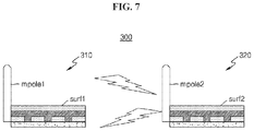
- FIGS. 5 through 7 are diagrams illustrating examples of configurations of a transmitter and a receiver of a wireless power transmission and communication system according to an example embodiment.
- a wireless power transmission and communication system 100 includes a transmitter 110 and a receiver 120 .
- the transmitter 110 includes a first surface wave antenna (indicated as “surf 1 ” in the drawing) installed on a metal wall and configured to transmit an evanescent electromagnetic wave flowing along a surface of the metal wall, and a first monopole antenna (indicated as “mpole 1 ” in the drawing) connected to the first surface wave antenna in parallel.
- the receiver 120 includes a second monopole antenna (indicated as “mpole 2 ” in the drawing) configured to receive an electromagnetic wave transmitted from the transmitter 110 .
- a transmitter for example, the transmitter 110 including the first surface wave antenna and the first monopole antenna
- a crew member present in another cabin in the ship may communicate with a crew member present in the cabin in which the transmitter 110 is installed, using the receiver 120 including the second monopole antenna as illustrated in FIG. 5 .
- an electromagnetic wave output from the first monopole antenna is received by the second monopole antenna
- an evanescent electromagnetic wave output from the first surface wave antenna may be radiated to the air from a curve while flowing along the metal wall and the second monopole antenna may receive such an electromagnetic wave.
- functions of the transmitter 110 and the receiver 120 may not be limited to transmitting and receiving power and/or signals, and they may perform bidirectional communication. That is, an electromagnetic wave output from the second monopole antenna may be received by the first monopole antenna and/or the first surface wave antenna.
- a wireless power transmission and communication system 200 includes a transmitter 210 and a receiver 220 , similar to the wireless power transmission and communication system 100 described above with reference to FIG. 5 .
- the transmitter 210 includes a first surface wave antenna (indicated as “surf 1 ” in the drawing) and a first monopole antenna (indicated as “mpole 1 ” in the drawing).
- the receiver 220 includes a second surface wave antenna (indicated as “surf 2 ” in the drawing).
- An electromagnetic wave output from the first surface wave antenna and/or the first monopole antenna may be transmitted through a metal wall and/or air, and the second surface wave antenna included in the receiver 220 may receive the electromagnetic wave.
- an evanescent electromagnetic wave generated in the first surface wave antenna and flowing along the metal wall may be received by the second surface wave antenna included in the receiver 220 .
- an evanescent electromagnetic wave generated in the first monopole antenna and transmitted through air may also be received by the second surface wave antenna.
- functions of the transmitter 210 and the receiver 220 illustrated in FIG. 6 may not be limited to transmitting and receiving power and/or signals, but they may perform bidirectional communication. That is, an electromagnetic wave output from the second surface wave antenna may be received by the first monopole antenna and/or the first surface wave antenna.
- a wireless power transmission and communication system 300 includes a transmitter 310 and a receiver 320 , similar to the wireless power transmission and communication system 100 described above with reference to FIG. 5 .
- the transmitter 310 includes a first surface wave antenna (indicated as “surf 1 ” in the drawing) and a first monopole antenna (indicated as “mpole 1 ” in the drawing).
- the receiver 320 includes a second surface wave antenna (indicated as “surf 2 ” in the drawing) and a second monopole antenna (indicated as “mpole 2 ” in the drawing).
- An electromagnetic wave output from the first surface wave antenna and/or the first monopole antenna may be transmitted through a metal wall and/or air, and the second surface wave antenna and the second monopole antenna included in the receiver 320 may receive the electromagnetic wave.
- an evanescent electromagnetic wave generated in the first surface wave antenna and flowing along the metal wall may be received by the second surface wave antenna included in the receiver 320 .
- an electromagnetic wave generated in the first monopole antenna and transmitted through air may be received by the second monopole antenna.
- functions of the transmitter 310 and the receiver 320 illustrated in FIG. 7 may not be limited to transmitting and receiving power and/or signals, but they may perform bidirectional communication. That is, an electromagnetic wave output from the second surface wave antenna and the second monopole antenna may be received by the first monopole antenna and the first surface wave antenna.
- FIG. 8 is a diagram illustrating an example of a location at which a repeater is installed according to an example embodiment.
- a wireless power transmission and communication system may further include a repeater configured to perform relaying between a transmitter and a receiver of the wireless power transmission and communication system.
- the repeater may include a third surface wave antenna configured to transmit and receive an evanescent electromagnetic wave flowing along a surface of a metal wall, and a third monopole antenna connected to the third surface wave antenna in parallel.
- the repeater may relay power and/or electromagnetic waves between the transmitter and the receiver.
- the repeater may be installed in cabin 2 .
- the repeater may relay power and/or electromagnetic waves transmitted from cabin 1 to cabin 3 , or relay power and/or electromagnetic waves transmitted from cabin 3 to cabin 1 .
- FIG. 9 is a diagram illustrating another example of a configuration of a wireless power transmission and communication system according to an example embodiment.
- a wireless power transmission and communication system 400 further includes a power supply 430 and an impedance matcher 440 .
- the power supply 430 may supply power to a transmitter 410 .
- the impedance matcher 440 may measure a voltage reflected from the transmitter 410 and compare a magnitude of the measured voltage to a reference voltage, and perform impedance matching based on a result of the comparing.
- the power supply 430 may supply, to the transmitter 410 , a voltage obtained through the impedance matching.
- the wireless power transmission and communication system 400 may improve a power and/or electromagnetic wave transmission efficiency and provide available maximum power.
- the power supply 430 may operate in one of a general mode and a fast mode.
- a magnitude of power to be supplied to the transmitter 410 in the fast mode may be controlled to be greater than a magnitude of power to be supplied to the transmitter 410 in the general mode.
- the power may be received by the receiver 420 and the received power may be supplied to a load through a rectifier.
- the power supply 430 may operate in the fast mode.
- a magnitude of power to be supplied to the transmitter 410 in the fast mode may be controlled to be greater than a magnitude of power to be supplied to the transmitter 410 in the general mode.
- the power supply 430 may set a magnitude of power to be supplied to the transmitter 410 to be great in proportion to the number of devices receiving power and/or electromagnetic waves from the transmitter 410 .
- FIG. 10 is a diagram illustrating an example of a concept of power or data transmission of a wireless power transmission and communication system according to an example embodiment.
- a metal wall may be provided in a body-centered cubic (BCC) crystal structure, or a body centric cuboid crystal structure as illustrated, or in a concavo-convex structure, that includes a convex portion, for example, a grain portion (illustrated as “G” in the drawing), and a concave portion, for example, a void portion (illustrated as “V” in the drawing), with a preset period A.
- BCC body-centered cubic
- V void portion
- a surface wave may be generated due to an interaction between an evanescent electromagnetic wave and the metal wall, and the evanescent electromagnetic wave may flow along a surface of the metal wall. That is, an evanescent electromagnetic wave generated in a transmitter which is an evanescent electromagnetic (indicated as “EM” in the drawing) wave source may be totally reflected by the convex portion (G) and the concave portion (V) formed based on the period (A) and thereby flow along the surface.
- EM evanescent electromagnetic
Landscapes
- Engineering & Computer Science (AREA)
- Computer Networks & Wireless Communication (AREA)
- Power Engineering (AREA)
- Signal Processing (AREA)
- Near-Field Transmission Systems (AREA)
- Transmitters (AREA)
- Details Of Aerials (AREA)
Abstract
Description
Claims (6)
Applications Claiming Priority (3)
| Application Number | Priority Date | Filing Date | Title |
|---|---|---|---|
| KR1020160076613A KR101804683B1 (en) | 2016-06-20 | 2016-06-20 | Wireless Power Transmission System and Communication System |
| KR10-2016-0076613 | 2016-06-20 | ||
| PCT/KR2016/015497 WO2017222133A1 (en) | 2016-06-20 | 2016-12-29 | Wireless power transmission system and communication system |
Publications (2)
| Publication Number | Publication Date |
|---|---|
| US20190214734A1 US20190214734A1 (en) | 2019-07-11 |
| US10797399B2 true US10797399B2 (en) | 2020-10-06 |
Family
ID=60784179
Family Applications (1)
| Application Number | Title | Priority Date | Filing Date |
|---|---|---|---|
| US16/310,790 Active 2037-05-01 US10797399B2 (en) | 2016-06-20 | 2016-12-29 | Wireless power transmission system and communication system |
Country Status (4)
| Country | Link |
|---|---|
| US (1) | US10797399B2 (en) |
| KR (1) | KR101804683B1 (en) |
| CN (1) | CN109891707A (en) |
| WO (1) | WO2017222133A1 (en) |
Families Citing this family (1)
| Publication number | Priority date | Publication date | Assignee | Title |
|---|---|---|---|---|
| KR102630057B1 (en) * | 2018-08-10 | 2024-01-25 | 엘지전자 주식회사 | Wireless power transreceiver, and image display apparatus including the same |
Citations (6)
| Publication number | Priority date | Publication date | Assignee | Title |
|---|---|---|---|---|
| KR100660051B1 (en) | 2005-08-11 | 2006-12-22 | 코마테크 주식회사 | Structure for broadband monopole antenna |
| KR20100013882A (en) | 2008-08-01 | 2010-02-10 | 한국전기연구원 | A wireless power transmission apparatus using surface wave and method thereof |
| KR20110014642A (en) | 2008-05-13 | 2011-02-11 | 퀄컴 인코포레이티드 | Receive antenna for wireless power transfer |
| US20110037322A1 (en) * | 2009-08-13 | 2011-02-17 | Panasonic Corporation | Wireless power transmission unit and power generator and power generation system with the wireless power unit |
| KR101533155B1 (en) | 2013-09-24 | 2015-07-02 | 한양대학교 산학협력단 | Antenna for Wearable Device |
| US20150223078A1 (en) | 2013-11-06 | 2015-08-06 | At&T Intellectual Property I, Lp | Surface-wave communications and methods thereof |
Family Cites Families (5)
| Publication number | Priority date | Publication date | Assignee | Title |
|---|---|---|---|---|
| US6366254B1 (en) * | 2000-03-15 | 2002-04-02 | Hrl Laboratories, Llc | Planar antenna with switched beam diversity for interference reduction in a mobile environment |
| KR100962593B1 (en) * | 2010-02-16 | 2010-06-11 | 동국대학교 산학협력단 | Method and apparatus for area based control of vacuum cleaner, and recording medium thereof |
| CN201812921U (en) * | 2010-06-17 | 2011-04-27 | 惠州市硕贝德通讯科技有限公司 | High-gain reduced surface-wave antenna |
| KR20120095144A (en) * | 2011-02-18 | 2012-08-28 | 이상재 | Mobile automatic cutter of belt loops |
| WO2015002658A1 (en) * | 2013-07-03 | 2015-01-08 | Hrl Laboratories, Llc | Electronically steerable, artificial impedance, surface antenna |
-
2016
- 2016-06-20 KR KR1020160076613A patent/KR101804683B1/en active IP Right Grant
- 2016-12-29 US US16/310,790 patent/US10797399B2/en active Active
- 2016-12-29 WO PCT/KR2016/015497 patent/WO2017222133A1/en active Application Filing
- 2016-12-29 CN CN201680088443.8A patent/CN109891707A/en active Pending
Patent Citations (7)
| Publication number | Priority date | Publication date | Assignee | Title |
|---|---|---|---|---|
| KR100660051B1 (en) | 2005-08-11 | 2006-12-22 | 코마테크 주식회사 | Structure for broadband monopole antenna |
| KR20110014642A (en) | 2008-05-13 | 2011-02-11 | 퀄컴 인코포레이티드 | Receive antenna for wireless power transfer |
| US20140103881A1 (en) | 2008-05-13 | 2014-04-17 | Qualcomm Incorporated | Repeaters for enhancement of wireless power transfer |
| KR20100013882A (en) | 2008-08-01 | 2010-02-10 | 한국전기연구원 | A wireless power transmission apparatus using surface wave and method thereof |
| US20110037322A1 (en) * | 2009-08-13 | 2011-02-17 | Panasonic Corporation | Wireless power transmission unit and power generator and power generation system with the wireless power unit |
| KR101533155B1 (en) | 2013-09-24 | 2015-07-02 | 한양대학교 산학협력단 | Antenna for Wearable Device |
| US20150223078A1 (en) | 2013-11-06 | 2015-08-06 | At&T Intellectual Property I, Lp | Surface-wave communications and methods thereof |
Also Published As
| Publication number | Publication date |
|---|---|
| US20190214734A1 (en) | 2019-07-11 |
| WO2017222133A1 (en) | 2017-12-28 |
| KR101804683B1 (en) | 2017-12-05 |
| CN109891707A (en) | 2019-06-14 |
Similar Documents
| Publication | Publication Date | Title |
|---|---|---|
| US10636565B2 (en) | Signal and power transmission system | |
| US10425126B2 (en) | Hybrid guided surface wave communication | |
| Domingo | Magnetic induction for underwater wireless communication networks | |
| CN105745786A (en) | A wave shaping device, an electronic device, and a system | |
| US20190049568A1 (en) | Remote surface sensing using guided surface wave modes on lossy media | |
| US20190154635A1 (en) | Subsurface sensing using guided surface wave modes on lossy media | |
| JP6471382B2 (en) | Magnetic wave antenna and magnetic wave communication apparatus using the same | |
| US10797399B2 (en) | Wireless power transmission system and communication system | |
| CN109309521A (en) | A kind of RTK base station apparatus, signal interaction system and method | |
| JP2010136135A (en) | Method for transmission and reception between electromagnetic wave interface device, and sheet-like two-dimensional electromagnetic wave transmitting medium and sheet-like electromagnetic wave transmitting medium | |
| CN111345015A (en) | Communication device and method in ship | |
| Aboderin | Antenna design for underwater applications | |
| Manteghi | An electrically small antenna for underwater applications | |
| Yukhanov et al. | Scattering characteristics of the Van-Atta waveguide array on the surface of a cylinder | |
| Merrill | Some early historical aspects of project sanguine | |
| Trinchero et al. | Design and optimization of the electromagnetic front-end for wireless sensors floating in dissipative media | |
| Baszynski et al. | Wireless energy transfer for industrial applications: Theory, available solutions and perspectives | |
| CN105846912A (en) | Frequency selection optimization system and deep penetration communication method | |
| RU2230431C2 (en) | Shipboard emergency radio communication system | |
| KR102105684B1 (en) | Apparatus and method for wireless communication | |
| Azam et al. | Slow Wave Coupling for Augmentation of Wireless Power Transfer in Noisy Environments | |
| US6218994B1 (en) | Small antennas for communication over sea ice | |
| US20240089743A1 (en) | Apparatus, methods and systems for improving coverage of wireless communication networks | |
| Takano et al. | Design of the transmission and reception antennas for beamed power transfer | |
| WO2014196722A1 (en) | Method and apparatus for performing antenna virtualization using polarimetric antenna in a wireless communication system |
Legal Events
| Date | Code | Title | Description |
|---|---|---|---|
| AS | Assignment |
Owner name: ULSAN NATIONAL INSTITUTE OF SCIENCE AND TECHNOLOGY Free format text: ASSIGNMENT OF ASSIGNORS INTEREST;ASSIGNORS:BIEN, FRANKLIN DON;ORUGANTI, SAR KIRAN;HEO, SANG HYUN;AND OTHERS;REEL/FRAME:049142/0045 Effective date: 20181113 Owner name: ULSAN NATIONAL INSTITUTE OF SCIENCE AND TECHNOLOGY, KOREA, REPUBLIC OF Free format text: ASSIGNMENT OF ASSIGNORS INTEREST;ASSIGNORS:BIEN, FRANKLIN DON;ORUGANTI, SAR KIRAN;HEO, SANG HYUN;AND OTHERS;REEL/FRAME:049142/0045 Effective date: 20181113 |
|
| FEPP | Fee payment procedure |
Free format text: ENTITY STATUS SET TO UNDISCOUNTED (ORIGINAL EVENT CODE: BIG.); ENTITY STATUS OF PATENT OWNER: SMALL ENTITY |
|
| STPP | Information on status: patent application and granting procedure in general |
Free format text: APPLICATION UNDERGOING PREEXAM PROCESSING |
|
| FEPP | Fee payment procedure |
Free format text: ENTITY STATUS SET TO SMALL (ORIGINAL EVENT CODE: SMAL); ENTITY STATUS OF PATENT OWNER: SMALL ENTITY |
|
| STPP | Information on status: patent application and granting procedure in general |
Free format text: APPLICATION DISPATCHED FROM PREEXAM, NOT YET DOCKETED |
|
| STPP | Information on status: patent application and granting procedure in general |
Free format text: NOTICE OF ALLOWANCE MAILED -- APPLICATION RECEIVED IN OFFICE OF PUBLICATIONS |
|
| STCF | Information on status: patent grant |
Free format text: PATENTED CASE |
|
| MAFP | Maintenance fee payment |
Free format text: PAYMENT OF MAINTENANCE FEE, 4TH YR, SMALL ENTITY (ORIGINAL EVENT CODE: M2551); ENTITY STATUS OF PATENT OWNER: SMALL ENTITY Year of fee payment: 4 |