US10728083B2 - Methods for orientation and tilt identification of photovoltaic systems and solar irradiance sensors - Google Patents
Methods for orientation and tilt identification of photovoltaic systems and solar irradiance sensors Download PDFInfo
- Publication number
- US10728083B2 US10728083B2 US15/598,596 US201715598596A US10728083B2 US 10728083 B2 US10728083 B2 US 10728083B2 US 201715598596 A US201715598596 A US 201715598596A US 10728083 B2 US10728083 B2 US 10728083B2
- Authority
- US
- United States
- Prior art keywords
- orientation
- tilt
- renewable energy
- solar irradiance
- computer processor
- Prior art date
- Legal status (The legal status is an assumption and is not a legal conclusion. Google has not performed a legal analysis and makes no representation as to the accuracy of the status listed.)
- Active, expires
Links
- 238000000034 method Methods 0.000 title claims abstract description 65
- 238000004519 manufacturing process Methods 0.000 claims abstract description 160
- 230000007613 environmental effect Effects 0.000 claims description 54
- 230000002596 correlated effect Effects 0.000 claims description 19
- 238000001514 detection method Methods 0.000 description 16
- 238000004891 communication Methods 0.000 description 15
- XLYOFNOQVPJJNP-UHFFFAOYSA-N water Substances O XLYOFNOQVPJJNP-UHFFFAOYSA-N 0.000 description 11
- 238000005259 measurement Methods 0.000 description 8
- 238000012544 monitoring process Methods 0.000 description 8
- 230000002349 favourable effect Effects 0.000 description 7
- 238000012806 monitoring device Methods 0.000 description 7
- 238000004422 calculation algorithm Methods 0.000 description 6
- 230000000052 comparative effect Effects 0.000 description 6
- 238000001914 filtration Methods 0.000 description 4
- 238000004088 simulation Methods 0.000 description 4
- 238000013459 approach Methods 0.000 description 3
- 230000008901 benefit Effects 0.000 description 3
- 238000013500 data storage Methods 0.000 description 3
- 230000008569 process Effects 0.000 description 3
- 230000005855 radiation Effects 0.000 description 3
- 239000007787 solid Substances 0.000 description 3
- 238000004364 calculation method Methods 0.000 description 2
- 238000010438 heat treatment Methods 0.000 description 2
- 238000009434 installation Methods 0.000 description 2
- VNWKTOKETHGBQD-UHFFFAOYSA-N methane Chemical compound C VNWKTOKETHGBQD-UHFFFAOYSA-N 0.000 description 2
- 238000000926 separation method Methods 0.000 description 2
- 238000004220 aggregation Methods 0.000 description 1
- 230000002776 aggregation Effects 0.000 description 1
- 239000000306 component Substances 0.000 description 1
- 238000005094 computer simulation Methods 0.000 description 1
- 230000001276 controlling effect Effects 0.000 description 1
- 238000001816 cooling Methods 0.000 description 1
- 239000008358 core component Substances 0.000 description 1
- 230000000875 corresponding effect Effects 0.000 description 1
- 230000000694 effects Effects 0.000 description 1
- 238000007519 figuring Methods 0.000 description 1
- 239000007789 gas Substances 0.000 description 1
- 230000007246 mechanism Effects 0.000 description 1
- 238000012986 modification Methods 0.000 description 1
- 230000004048 modification Effects 0.000 description 1
- 239000003345 natural gas Substances 0.000 description 1
- 238000005457 optimization Methods 0.000 description 1
- 238000004806 packaging method and process Methods 0.000 description 1
- 238000005086 pumping Methods 0.000 description 1
- 238000002922 simulated annealing Methods 0.000 description 1
Images


Classifications
-
- H—ELECTRICITY
- H04—ELECTRIC COMMUNICATION TECHNIQUE
- H04L—TRANSMISSION OF DIGITAL INFORMATION, e.g. TELEGRAPHIC COMMUNICATION
- H04L41/00—Arrangements for maintenance, administration or management of data switching networks, e.g. of packet switching networks
- H04L41/02—Standardisation; Integration
- H04L41/0246—Exchanging or transporting network management information using the Internet; Embedding network management web servers in network elements; Web-services-based protocols
- H04L41/026—Exchanging or transporting network management information using the Internet; Embedding network management web servers in network elements; Web-services-based protocols using e-messaging for transporting management information, e.g. email, instant messaging or chat
-
- G—PHYSICS
- G06—COMPUTING; CALCULATING OR COUNTING
- G06F—ELECTRIC DIGITAL DATA PROCESSING
- G06F30/00—Computer-aided design [CAD]
- G06F30/20—Design optimisation, verification or simulation
-
- F—MECHANICAL ENGINEERING; LIGHTING; HEATING; WEAPONS; BLASTING
- F24—HEATING; RANGES; VENTILATING
- F24S—SOLAR HEAT COLLECTORS; SOLAR HEAT SYSTEMS
- F24S50/00—Arrangements for controlling solar heat collectors
- F24S50/20—Arrangements for controlling solar heat collectors for tracking
-
- F—MECHANICAL ENGINEERING; LIGHTING; HEATING; WEAPONS; BLASTING
- F24—HEATING; RANGES; VENTILATING
- F24S—SOLAR HEAT COLLECTORS; SOLAR HEAT SYSTEMS
- F24S2201/00—Prediction; Simulation
-
- Y—GENERAL TAGGING OF NEW TECHNOLOGICAL DEVELOPMENTS; GENERAL TAGGING OF CROSS-SECTIONAL TECHNOLOGIES SPANNING OVER SEVERAL SECTIONS OF THE IPC; TECHNICAL SUBJECTS COVERED BY FORMER USPC CROSS-REFERENCE ART COLLECTIONS [XRACs] AND DIGESTS
- Y02—TECHNOLOGIES OR APPLICATIONS FOR MITIGATION OR ADAPTATION AGAINST CLIMATE CHANGE
- Y02E—REDUCTION OF GREENHOUSE GAS [GHG] EMISSIONS, RELATED TO ENERGY GENERATION, TRANSMISSION OR DISTRIBUTION
- Y02E10/00—Energy generation through renewable energy sources
- Y02E10/40—Solar thermal energy, e.g. solar towers
- Y02E10/47—Mountings or tracking
Definitions
- This patent describes the methodologies for identifying orientation and tilt of PV systems based on energy production and orientation and tilt of solar irradiance sensors based on the solar irradiance observed.
- a correlation based methodology leverages a PV production model and iterates through orientation and tilt in order to identify a system's orientation and tilt.
- a correlation based methodology leverages solar irradiance models and iterates through orientation and tilt in order to identify a solar irradiance sensor's orientation and tilt.
- An energy production skew based methodology leverages differences between morning and evening production in order to identify a system's tilt.
- a measured solar irradiance skew based methodology leverages differences between morning and evening observed solar irradiance in order to identify a sensor's tilt.
- the present invention relates to methods and systems for identifying PV system and solar irradiance sensor orientation and tilt based on energy production, energy received, simulated energy production, estimated energy received, production skew, and energy received skew.
- the present invention relates to systems and methods for detecting orientation and tilt of a PV system based on energy production and simulated energy production; for detecting the orientation and tilt of a solar irradiance sensor based on solar irradiance observation and simulated solar irradiance observation; for detecting orientation of a PV system based on energy production and energy production skew; and for detecting orientation of a solar irradiance sensor based on solar irradiance observation and solar irradiance observation skew.
- a computer processor implemented method of identifying the orientation and tilt of a renewable energy system comprising the steps of; providing a set of renewable energy systems having at least two renewable energy systems each having an orientation and tilt angle pair to provide a set of orientation and tilt known renewable energy systems in a computer processor; determining environmental conditions for each of the orientation and tilt known renewable energy systems to provide environmental conditions at each orientation and tilt known renewable energy system in a computer processor; determining simulated production data by a computer processor based on the environmental conditions at each orientation and tilt angle pair to provide simulated production data for each orientation and tilt angle pair known renewable energy system; storing the orientation and tilt angle pair and simulated production data in a computer processor; providing at least one orientation and tilt unknown renewable energy system in a computer processor; calculating by the computer processor a correlation for each orientation and tilt unknown renewable energy systems production data to the simulated production data for each orientation and tilt angle pair known renewable energy systems; setting the orientation and tilt for the orientation and tilt unknown renewable energy systems to the most correlated orientation and tilt known renewable renewable energy
- a computer processor implemented method of identifying the orientation and tilt of a solar irradiance sensor comprising the steps of; providing a set of solar irradiance sensors having at least two solar irradiance sensors each having an orientation and tilt angle pair to provide a set of orientation and tilt known solar irradiance sensors in a computer processor; determining environmental conditions for each of the orientation and tilt known solar irradiance sensors to provide environmental conditions at each orientation and tilt known solar irradiance sensors in a computer processor; determining simulated production data by a computer processor based on the environmental conditions at each orientation and tilt angle pair to provide simulated production data for each orientation and tilt angle pair known solar irradiance sensor; storing the orientation and tilt angle pair and simulated production data in a computer processor; providing at least one orientation and tilt unknown solar irradiance sensor in a computer processor; calculating by the computer processor a correlation for each orientation and tilt unknown solar irradiance sensors production data to the simulated production data for each
- a computer processor implemented method of identifying the orientation of a renewable energy system comprising the steps of; providing at least one orientation unknown renewable energy system having production data in a computer processor; storing the production data in a computer processor; filtering the production data day by day for favorable weather conditions by a computer processor to provide filtered production data for each filtered day; identifying and saving the start of production, peak of production and end of production for each filtered day in a computer processor; calculating a skew of observation for one of the at least one orientation unknown renewable energy systems by a computer processor according to the start of production, peak of production and end of production for each filtered day; calculating an orientation for the one of the at least one orientation unknown renewable energy systems by a computer processor according to the skew of observation; setting the orientation for the one of the at least one orientation unknown renewable energy systems to become an orientation known renewable energy system that becomes part of a set of orientation known renewable energy systems in a computer processor.
- a computer processor implemented method of identifying the orientation of a solar irradiance sensor comprising the steps of: providing an orientation-unknown solar irradiance sensor having solar irradiance sensor data in a computer processor; storing the solar irradiance sensor data in a computer processor; filtering the solar irradiance sensor data day by day for favorable weather conditions by a computer processor to provide filtered solar irradiance sensor data for each filtered day; identifying and saving the start of production, peak of production and end of production for each filtered day in a computer processor; calculating a skew of observation for each the solar irradiance sensor by a computer processor according to the start of production, peak of production and end of production for each filtered day; calculating the orientation of the solar irradiance sensor by a computer processor according to the skew of observation; setting the orientation for the orientation-unknown solar irradiance sensor to become an orientation-known solar irradiance sensor that becomes part
- FIG. 1 depicts the present invention
- FIG. 2 depicts the present invention
- FIG. 3 depicts the present invention
- FIG. 4 depicts the present invention
- FIG. 5 depicts the present invention
- FIG. 6 depicts the present invention
- FIG. 7 depicts the present invention
- FIG. 8 depicts the present invention
- FIG. 9 depicts the present invention
- FIG. 10 depicts the present invention
- FIG. 11 depicts the present invention
- FIG. 12 depicts the present invention.
- FIG. 13 depicts the present invention.
- FIGS. 1-5 provide examples of a monitored renewable energy system (more specifically a photovoltaic array solar panel also referred to herein as a solar photovoltaic system or solar powered system) from which information may be obtained.
- a server 10 there is a server 10 and at least one monitored renewable energy system (e.g. 102 , 104 , 106 , 108 , 110 , 112 ) which is provided to a user or consumer.
- the data server may be a single computer, a distributed network of computers, a dedicated server, any computer processor implemented device or a network of computer processor implemented devices, as would be appreciated by those of skill in the art.
- the monitored renewable energy system may have background constants that are entered into the system during data setup; populating this part of the data structure is one of the initial steps to the process.
- Background constants may include: (1) Full Calendar with sunrise and sunset according to latitude throughout the year; (2) Insolation or ‘incident solar radiation’: This is the actual amount of sunlight falling on a specific geographical location. There are expected amounts of radiation which will fall on an area each day, as well as an annual figure. Specific Insolation is calculated as kWh/m2/day. The importance of this variable is that it can combine several other Background Constants; and (3) Location Functionality. It is envisioned that some of this information may be input and some may be determined automatically.
- each system may be determined, and forms a part of the methods used to determine the geographic average of the renewable energy systems. While there are different specific methods of implementing Location Functionality, generally this relies on a large database of locations which are tied to zones. Because the relational distances between the zones are stored within the software, the distances between any two locations can then be easily and accurately calculated.
- production data refers to any data that is received from the renewable energy system and/or solar irradiance sensor.
- the energy generated by each monitored renewable energy system and/or solar irradiance sensor is recorded as production data and the data server may then determine comparative information based upon at least one of the background constant, the diagnostic variable, the system coefficient and the energy generated to determine a comparative value of the monitored renewable energy system.
- the term comparative value is intended to include any value that compares one system to another system or a group of systems. For example, this may be as simple as an “underperforming” designation when the system's performance is less than another system or group of systems performance in terms of power generated.
- a sample system may have at least one inverter ( 14 ) in communication with the monitored renewable energy system (e.g. 50 , 30 ).
- the inverter ( 14 ) is an electronic circuit that converts direct current (DC) to alternating current (AC).
- the monitored renewable energy system e.g. 30 , 50
- the monitored renewable energy system may be at least partially powered by at least one alternate energy source.
- the communication node may be further comprising a data storage means for storing usage information.
- the communication node ( 64 ) may be a computer with a hard drive that acts as a data storage means for storing usage information.
- the generation monitoring device may be selected from the group consisting of pulse meter, temperature meter, electromechanical meter, solid state meter, flow meter, electric meter, energy meter and watt meter. There may also be at least one return monitoring device in communication with the inverter which calculates the energy returned to a grid by the system.
- the monitored renewable energy system may be, for example, a solar system, solar panel system, photovoltaic, thermal, wind powered, geothermal, hydropower.
- a secondary energy source e.g. 52
- the generation monitoring device may be any type of meter, by way of example, this may include a pulse meter, temperature meter, electromechanical meter, solid state meter, flow meter, electric meter, energy meter and watt meter.
- An installation will have a communication node or hub set up at the location with the system.
- One of the communication nodes may act as a hub.
- These devices connect to the internet and send the data collected by the nodes to the Server. They have the following properties:
- the hub has a web server and connects to a standard internet connection (Ethernet). It does not require a computer or other device to make this connection.
- Each hub has its own unique IP or DNS address.
- the hub is configured by a web browser. The web browser allows the hub to have specific nodes assigned to it.
- This set up feature will allow another hub in the area to be set up with its own nodes so that all can operate wirelessly without disruption. Also, the hub is able to configure specific aspects of the hub, such as the connection with the server, data recording and time settings and the ability to configure the attached nodes, including their recording properties.
- Each installation may have two or more Data Nodes. These are typically connected wirelessly to the Hub, and connected directly to the inputs/outputs from the Solar Hot Water system. They communicate constantly with the Hub, transferring data which the Hub then sends up to the server. They may have the following properties:
- the first Required Node connects to a flow meter attached to the Water Tank that is connected to the Solar Hot Water system. This Node will operate as a pulse meter, ‘clicking’ whenever a unit (either a gallon or a liter) of hot water passes from the tank.
- the second Required Node connects to either the electric panel at the switch for the Hot Water tank's electric power OR to a flow/other meter for gas/oil to the secondary heater for the Hot Water tank.
- the Node may have a data storage means for storing flow/usage information. Together, the data gathered from these Required Node connections allow the software on the serve to convert the utilized hot water into an accurate reading of utilized solar energy by subtracting the energy required to by the secondary heating mechanism.
- the term utilized generation refers to the energy generated by the at-premise power system, less any energy that has not been consumed by the at premise power system (e.g. the energy used to heat water that remains in the tank and is not subsequently used).
- the term “at-premise power system” is one type of monitored renewable energy system, as claimed.
- the components node ( 100 ), hub ( 102 ) and server ( 10 ) make up the required core components needed to accurately measures the actual usable output from a Solar Hot Water (SHW) system.
- the hub ( 102 ) connects to multiple nodes ( 100 ) which simultaneously measure the secondary power going into the system along with the hot water going out. Controlling for any background power requirements (e.g. for pumping), it can measure the usable BTUs created by solar by analyzing the measurements at the server ( 104 ) level.
- the renewable energy system may be a solar system, solar panel system, photovoltaic, thermal, wind powered, geothermal, hydropower or any other renewable energy system.
- the terms at-premises, on premises and at-premise are interchangeable and equivalent. Additionally, for those interested in heating and cooling their dwelling via renewable energy, geothermal heat pump systems that tap the constant temperature of the earth, which is around 7 to 15 degrees Celsius a few feet underground, are an option and save money over conventional natural gas and petroleum-fueled heat approaches.
- the method may further comprise the steps of: monitoring the system from a remote location; and monitoring the utilized generation from a remote location.
- the method may comprise the steps of: generating an alert when the customer variables are a prescribed percentage different than historical averages.
- the method may also comprise the steps of monitoring and storing the consumer's customer variables and utilized generation.
- the present invention provides a computer processor implemented method of identifying the orientation and tilt of a renewable energy system (e.g. 102 , 106 , 108 ), the method comprising the steps of: providing a set of renewable energy systems having at least two renewable energy systems each having an orientation and tilt angle pair to provide a set of orientation and tilt known renewable energy systems in a computer processor.
- the term “computer processor” is intended to include any computing device, such as a computer, laptop, smart phone and tablet device.
- the term “orientation and tilt known renewable energy systems” are, just as the name implies, renewable energy systems for which it is known what the orientation and tilt are.
- the term “orientation and tilt unknown renewable energy systems” are, just as the name implies, renewable energy systems for which the orientation and tilt is not known (or unknown).
- determining environmental conditions for each of the orientation and tilt known renewable energy system to provide environmental conditions at each orientation and tilt known renewable energy system in a computer processor; determining simulated production data by a computer processor based on said environmental conditions at each orientation and tilt angle pair to provide simulated production data for each orientation and tilt angle pair known renewable energy system; storing the orientation and tilt angle pair and simulated production data in a computer processor; providing at least one orientation and tilt unknown renewable energy system in a computer processor; calculating by the computer processor a correlation for each orientation and tilt unknown renewable energy systems production data to said simulated production data for each orientation and tilt angle pair known renewable energy systems; setting the orientation and tilt for the orientation and tilt unknown renewable energy systems to the most correlated orientation and tilt known renewable energy systems to become a correlated simulated orientation and tilt known renewable energy systems that is part of the set of renewable energy systems having at least two renewable energy systems each having an orientation and tilt angle pair in said computer processor.
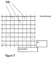
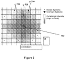
- FIGS. 7-9 depict a triangulation method of correlating according to the present invention.
- location known renewable energy systems ( 700 ) are marked on an orientation and tilt grid.
- An orientation and tilt unknown renewable energy system ( 702 ) is shown in FIG. 9 .
- One triangulation method may be to set the orientation and tilt to the highest correlated location known system's orientation and tilt.
- the orientation and tilt pair and production data are stored in a computer processor.
- FIG. 9 depicts correlating a location-unknown renewable energy system ( 702 ) to at least one location known renewable energy system ( 700 ).
- the step of correlating a location may be according to Geospatial interpolation methods, included but not limited to kriging, inverse distance weighting, bilinear interpolation, bicubic interpolation, Barnes interpolation, and spline interpolation (for latitude and longitude).
- Geospatial interpolation methods included but not limited to kriging, inverse distance weighting, bilinear interpolation, bicubic interpolation, Barnes interpolation, and spline interpolation (for latitude and longitude).
- Correlation is calculated by taking 2 sets of time series data (in our case from an unknown system and a known system) and calculating Pearson's correlation coefficient using those datasets. Using a computer algorithm we calculate correlation from the formula below, where r is correlation, X is data from one set, and Y is data from the other.
- the correlation based identification logic is for identifying a renewable energy system's orientation and tilt based on the correlation of the system's energy production with observed or simulated energy production at a known location. This logic can also identify an environmental sensor's orientation and tilt based on the correlation of the sensor's observations with observed or simulated environmental conditions.
- Production data could come from, without limitation, PV System (kW or kWh), Solar thermal system (kW or kWh), Concentrated solar power system (kW or kWh) and Wind turbine (kW or kWh).
- Sensor data could come from, without limitation, Pyranometer (W/m ⁇ circumflex over ( ) ⁇ 2 or Wh/m ⁇ circumflex over ( ) ⁇ 2), Pyrheliometer (W/m ⁇ circumflex over ( ) ⁇ 2 or Wh/m ⁇ circumflex over ( ) ⁇ 2), PV reference cell (W/m ⁇ circumflex over ( ) ⁇ 2 or Wh/m ⁇ circumflex over ( ) ⁇ 2), Radiometer (W/m ⁇ circumflex over ( ) ⁇ 2 or Wh/m ⁇ circumflex over ( ) ⁇ 2), Pyrgeometer (W/m ⁇ circumflex over ( ) ⁇ 2 or Wh/m ⁇ circumflex over ( ) ⁇ 2), Anemometer (mph or m/s).
- This type of data consists of a hardware measurement (units listed beside hardware) and a corresponding point in time or time interval, producing a time series of data (multiple time points and data). For example, monitored PV production data is measured every 5 minutes, resulting in a 1 day dataset containing 288 measurements and timestamp pairs.
- the production data may be simulated production data according to environmental conditions at the orientation and tilt pair and the step of correlating by the computer processor each orientation and tilt-unknown renewable energy system to at least one orientation and tilt-known renewable energy system is according to the orientation and tilt-known renewable energy systems orientation and tilt and the simulated production data.
- the environmental conditions at the orientation and tilt pair may be estimated and/or observed.
- the renewable energy systems' production data may be selected from the group consisting of photovoltaic system production data, solar thermal system production data, concentrated solar power system production data and wind turbine production data.
- Another aspect of the present invention provides a computer processor implemented method of identifying the orientation and tilt of a solar irradiance sensor, the method comprising the steps of; providing a set of solar irradiance sensors having at least two solar irradiance sensors each having an orientation and tilt angle pair to provide a set of orientation and tilt known solar irradiance sensors in a computer processor; determining environmental conditions for each of the orientation and tilt known solar irradiance sensors to provide environmental conditions at each orientation and tilt known solar irradiance sensors in a computer processor; determining simulated production data by a computer processor based on said environmental conditions at each orientation and tilt angle pair to provide simulated production data for each orientation and tilt angle pair known solar irradiance sensor; storing the orientation and tilt angle pair and simulated production data in a computer processor; providing at least one orientation and tilt unknown solar irradiance sensor in a computer processor; calculating by said computer processor a correlation for each orientation and tilt unknown solar irradiance sensors production data to said simulated production data for each orientation
- a computer processor implemented method of identifying the orientation of a renewable energy system comprising the steps of; providing at least one orientation unknown renewable energy system having production data in a computer processor; storing the production data in a computer processor; filtering said production data day by day for favorable weather conditions by a computer processor to provide filtered production data for each filtered day; identifying and saving the start of production, peak of production and end of production for each filtered day in a computer processor; calculating a skew of observation for one of said at least one orientation unknown renewable energy systems by a computer processor according to the start of production, peak of production and end of production for each filtered day; calculating an orientation for said one of said at least one orientation unknown renewable energy systems by a computer processor according to said skew of observation; setting said orientation for said one of said at least one orientation unknown renewable energy systems to become an orientation known renewable energy system that becomes part of a set of orientation known renewable energy systems in a computer processor.
- the production data may be simulated production data according to environmental conditions at the
- a computer processor implemented method of identifying the orientation of a solar irradiance sensor comprising the steps of: providing an orientation-unknown solar irradiance sensor having solar irradiance sensor data in a computer processor; storing the solar irradiance sensor data in a computer processor; filtering the solar irradiance sensor data day by day for favorable weather conditions by a computer processor to provide filtered solar irradiance sensor data for each filtered day; identifying and saving the start of production, peak of production and end of production for each filtered day in a computer processor; calculating a skew of observation for each said solar irradiance sensor by a computer processor according to the start of production, peak of production and end of production for each filtered day; calculating the orientation of said solar irradiance sensor by a computer processor according to said skew of observation; setting said orientation for the orientation-unknown solar irradiance sensor to become an orientation-known solar irradiance sensor that
- FIG. 6 depicts an irradiance map. Note that typically, an irradiance map may provide the amount of solar radiation in kWh/m 2 /day. Theoretically, hardware oriented due North or South should have even production or solar irradiance measurements in the morning and evening and deviations from this relationship are caused by changes in orientation.
- the Methodology is comprised of the following, background variables, input parameters and logic based on those variables parameters.
- Renewable energy systems include, but are not limited to, solar power systems and wind power systems.
- solar irradiance sensor with unknown or incorrect orientation feed This is a feed providing environmental condition data and time from an environmental sensor with an unknown or incorrect orientation.
- Environmental sensors include, but are not limited to, solar irradiance sensors, wind sensors, and temperature sensors.
- solar irradiance sensor feed This feed provides data about the amount of solar irradiance received by a solar irradiance sensor.
- Variables include solar irradiance observed, time, and location among others.
- PV system production models are models that simulate the energy production for a PV system using environmental condition models/feeds.
- Methods for solving search and optimization problems may include, but are not limited to, brute force search, simulated annealing, and greedy algorithm.
- environmental condition models and feeds There may be environmental condition models and feeds. These are models and feeds that provide data on environmental conditions vital to renewable energy production. This includes, but is not limited to, solar irradiance, wind, and temperature models and feeds.
- renewable energy system production models There may be renewable energy system production models. These are models that simulate the energy production for a variety of renewable energy systems using environmental condition models/feeds. These renewable energy system models include, but are not limited to, photovoltaic, solar thermal, and wind models.
- weather filter logic This is logic that leverages the relationship between favorable weather and high renewable energy production and filters days of production for those days with good weather.
- observation event detection logic This is empirically derived logic for identifying the start, peak, and end of production for a PV system and observed irradiance for a solar irradiance sensor.
- correlation based orientation and tilt identification logic This is logic for identifying PV system orientation and tilt based on the correlation of energy production by systems at the same location with similar orientation and tilt. This is logic also for identifying solar irradiance sensor orientation and tilt based on correlation of measured solar irradiance at the same location with similar orientation and tilt. This correlation occurs because hardware with similar orientation and tilt receive similar solar irradiance.
- correlation based PV orientation and tilt detection model This is a model that detects orientation and tilt of PV systems using correlation based identification logic.
- the model leverages search problem methods, environmental condition models/feeds, and PV system production models in order to simulate production, which is then correlated with the PV system production feed to identify orientation and tilt.
- a correlation based solar irradiance sensor orientation and tilt detection model This is a model that detects orientation and tilt of solar irradiance sensors using correlation based identification logic.
- the model leverages search problem methods and environmental condition models/feeds in order to estimate solar irradiance, which is then correlated with the solar irradiance sensor feed to identify orientation and tilt.
- observation skew based PV orientation detection model There may be an observation skew based PV orientation detection model. This is a model that detects orientation of PV systems using observation skew based identification logic. The model leverages weather filter logic and observation event detection logic in order to identify orientation.
- observation skew based solar irradiance sensor orientation detection model This is a model that detects orientation of solar irradiance sensors using observation skew based identification logic.
- the model leverages weather filter logic and observation event detection logic in order to identify orientation.
- the Correlation Based Renewable Energy System Location Identification Model approach identifies the location of a renewable energy system by finding the systems it is most highly correlated with in terms of energy production.
- the correlation approach works, because renewable energy systems share the same environmental conditions if they are located in the same area, and they therefore will have similar behavior in terms of output. This correlation holds on a large geographic scale, so we can use the correlation effect to find neighboring renewable energy systems, and therefore to locate a renewable energy system if we have other systems with known locations to start with.
- “known” locations can be simulated and the aforementioned logic can be applied.
- Orientation angle Angle at which PV system is directed.
- Tilt angle Angle at which PV system is raised.
- Environmental conditions Estimated or observed solar irradiance, wind speed, temperature, and other variables.
- PV system production Observed PV system energy generation.
- Simulated PV system production Simulated PV system energy generation given environmental conditions at orientation and tilt pairs.
- Orientation angle Angle at which solar irradiance sensor is directed.
- Tilt angle Angle at which solar irradiance sensor is raised
- Environmental conditions Estimated or observed solar irradiance, wind speed, temperature, and other variables.
- Simulated solar irradiance sensor observations Simulated solar irradiance measurements given environmental conditions at orientation and tilt pairs.
- PV system production Observed PV system energy generation.
- TimeOfStart Time of start of PV system energy generation.
- TimeOfPeak Time of start of PV system energy generation.
- TimeOfEnd Time of start of PV system energy generation.
- Skew Time difference between start to peak of production and peak to end of production.
- Orientation angle Angle at which solar irradiance sensor is directed.
- Time of observation start Time of start of solar irradiance sensor observation
- the present invention helps to understand irradiance sensor orientation and tilt and PV system orientation and tilt. It is important to know the orientation and tilt of irradiance sensors as this explains how the irradiance sensor is collecting data, which is required to fully understand the physical solar resource that is being measured. Information on these solar resources can then be applied to solve a variety of problems. Knowing orientation and tilt of a PV system explains how the PV system is configured relative to the available solar resources, which is required to fully understand how the PV system is converting the input solar resource into PV output energy. The information on the PV system's output can then be applied to solve a variety of problems. There are many situations in which verifying the orientation and tilt of a PV system or an irradiance sensor could be important.
- orientation and tilt information may be a critical part of the estimation process (e.g., to forecast system output one may need to assess historical behavior/performance under different weather conditions, so knowing the orientation and tilt allows one to link the performance and weather data together).
- Orientation and tilt detection of photovoltaic system may be determined using system energy production and/or using simulated system energy production.
- the orientation and tilt detection of a solar irradiance sensor may be determined using sensor solar irradiance observation and/or using simulated solar irradiance observation.
- the orientation detection of photovoltaic systems may be determined using system energy production and/or using skew of production.
- Orientation detection of solar irradiance sensor may be determined using sensor solar irradiance observation and/or using skew of observation.
- Clean configuration data is the foundation for most fleet performance modeling analytics, but large-scale deployments' data on location, orientation, and tilt are generally subject to human error. We will cover a number of techniques to automatically validate location, orientation and tilt data.
- Location detection Combining three methodologies to determine location is often accurate within 10 miles.
- Solar noon By statistically determining a system's solar noon, the system's longitude can be extracted from astronomical calculations
- System location can be triangulated by correlating the system's production with production data from a network of solar projects with known locations.
- Weather & irradiance model simulations By simulating production using historical weather data and satellite-based irradiance models, an installed system's location can be determined by comparing simulated vs. actual production.
- Orientation and tilt detection Combining two methodologies to determine orientation and tilt provides solid data-quality guardrails.
- System orientation is indicated by the time difference between start to peak, and peak to end, of a typical system production profile.
- Orientation and tilt can be found by comparing actual vs. simulated output from a search through potential orientation and tilt angles.
Landscapes
- Engineering & Computer Science (AREA)
- Physics & Mathematics (AREA)
- Theoretical Computer Science (AREA)
- General Engineering & Computer Science (AREA)
- Computer Hardware Design (AREA)
- Evolutionary Computation (AREA)
- Geometry (AREA)
- General Physics & Mathematics (AREA)
- Computer Networks & Wireless Communication (AREA)
- Signal Processing (AREA)
- Life Sciences & Earth Sciences (AREA)
- Sustainable Development (AREA)
- Sustainable Energy (AREA)
- Thermal Sciences (AREA)
- Chemical & Material Sciences (AREA)
- Combustion & Propulsion (AREA)
- Mechanical Engineering (AREA)
- Photometry And Measurement Of Optical Pulse Characteristics (AREA)
Abstract
Description
The correlation based identification logic is for identifying a renewable energy system's orientation and tilt based on the correlation of the system's energy production with observed or simulated energy production at a known location. This logic can also identify an environmental sensor's orientation and tilt based on the correlation of the sensor's observations with observed or simulated environmental conditions.
Skew=abs(median(TimeOfPeak)−median(TimeOfStart))−abs(median(TimeOfPeak)−median(TimeOfEnd))
Orientation=Skew*0.7+180
Skew=abs(median(TimeOfPeak)−median(TimeOfStart))−abs(median(TimeOfPeak)−median(TimeOfEnd))
Orientation=Skew*0.7+180
Claims (17)
Priority Applications (1)
| Application Number | Priority Date | Filing Date | Title |
|---|---|---|---|
| US15/598,596 US10728083B2 (en) | 2010-05-10 | 2017-05-18 | Methods for orientation and tilt identification of photovoltaic systems and solar irradiance sensors |
Applications Claiming Priority (5)
| Application Number | Priority Date | Filing Date | Title |
|---|---|---|---|
| US12/777,235 US8862432B2 (en) | 2007-02-12 | 2010-05-10 | Automatic system information determination of distributed renewable energy systems |
| US201161576313P | 2011-12-15 | 2011-12-15 | |
| US201161576315P | 2011-12-15 | 2011-12-15 | |
| US13/681,803 US9686122B2 (en) | 2010-05-10 | 2012-11-20 | Methods for orientation and tilt identification of photovoltaic systems and solar irradiance sensors |
| US15/598,596 US10728083B2 (en) | 2010-05-10 | 2017-05-18 | Methods for orientation and tilt identification of photovoltaic systems and solar irradiance sensors |
Related Parent Applications (1)
| Application Number | Title | Priority Date | Filing Date |
|---|---|---|---|
| US13/681,803 Division US9686122B2 (en) | 2010-05-10 | 2012-11-20 | Methods for orientation and tilt identification of photovoltaic systems and solar irradiance sensors |
Publications (2)
| Publication Number | Publication Date |
|---|---|
| US20170257255A1 US20170257255A1 (en) | 2017-09-07 |
| US10728083B2 true US10728083B2 (en) | 2020-07-28 |
Family
ID=48608869
Family Applications (2)
| Application Number | Title | Priority Date | Filing Date |
|---|---|---|---|
| US13/681,803 Active 2032-01-07 US9686122B2 (en) | 2010-05-10 | 2012-11-20 | Methods for orientation and tilt identification of photovoltaic systems and solar irradiance sensors |
| US15/598,596 Active 2031-08-22 US10728083B2 (en) | 2010-05-10 | 2017-05-18 | Methods for orientation and tilt identification of photovoltaic systems and solar irradiance sensors |
Family Applications Before (1)
| Application Number | Title | Priority Date | Filing Date |
|---|---|---|---|
| US13/681,803 Active 2032-01-07 US9686122B2 (en) | 2010-05-10 | 2012-11-20 | Methods for orientation and tilt identification of photovoltaic systems and solar irradiance sensors |
Country Status (1)
| Country | Link |
|---|---|
| US (2) | US9686122B2 (en) |
Cited By (1)
| Publication number | Priority date | Publication date | Assignee | Title |
|---|---|---|---|---|
| US10817936B2 (en) * | 2019-02-07 | 2020-10-27 | Melanie Susan HUMMER | Fractionalized interest rate swaps |
Families Citing this family (40)
| Publication number | Priority date | Publication date | Assignee | Title |
|---|---|---|---|---|
| US9322951B2 (en) | 2007-02-12 | 2016-04-26 | Locus Energy, Inc. | Weather and satellite model for estimating solar irradiance |
| US9686122B2 (en) | 2010-05-10 | 2017-06-20 | Locus Energy, Inc. | Methods for orientation and tilt identification of photovoltaic systems and solar irradiance sensors |
| US10564315B2 (en) | 2010-05-10 | 2020-02-18 | Locus Energy, Inc. | Methods for location identification of renewable energy systems |
| US8682585B1 (en) * | 2011-07-25 | 2014-03-25 | Clean Power Research, L.L.C. | Computer-implemented system and method for inferring operational specifications of a photovoltaic power generation system |
| US10140401B1 (en) | 2011-07-25 | 2018-11-27 | Clean Power Research, L.L.C. | System and method for inferring a photovoltaic system configuration specification with the aid of a digital computer |
| US9638831B1 (en) | 2011-07-25 | 2017-05-02 | Clean Power Research, L.L.C. | Computer-implemented system and method for generating a risk-adjusted probabilistic forecast of renewable power production for a fleet |
| US10663500B2 (en) | 2011-07-25 | 2020-05-26 | Clean Power Research, L.L.C. | System and method for estimating photovoltaic energy generation through linearly interpolated irradiance observations with the aid of a digital computer |
| US10599747B1 (en) | 2011-07-25 | 2020-03-24 | Clean Power Research, L.L.C. | System and method for forecasting photovoltaic power generation system degradation |
| US8165812B2 (en) | 2011-07-25 | 2012-04-24 | Clean Power Research, L.L.C. | Computer-implemented system and method for estimating power data for a photovoltaic power generation fleet |
| US9880230B1 (en) | 2011-07-25 | 2018-01-30 | Clean Power Research, L.L.C. | System and method for inferring operational specifications of a photovoltaic power generation system using net load with the aid of a digital computer |
| US10797639B1 (en) | 2011-07-25 | 2020-10-06 | Clean Power Research, L.L.C. | System and method for performing power utility remote consumer energy auditing with the aid of a digital computer |
| US9645180B1 (en) | 2011-07-25 | 2017-05-09 | Clean Power Research, L.L.C. | System and method for estimating photovoltaic energy generation for use in photovoltaic fleet operation with the aid of a digital computer |
| US11068563B2 (en) | 2011-07-25 | 2021-07-20 | Clean Power Research, L.L.C. | System and method for normalized ratio-based forecasting of photovoltaic power generation system degradation with the aid of a digital computer |
| US9411073B1 (en) | 2011-07-25 | 2016-08-09 | Clean Power Research, L.L.C. | Computer-implemented system and method for correlating satellite imagery for use in photovoltaic fleet output estimation |
| US10663620B2 (en) | 2012-05-30 | 2020-05-26 | Neo Virtus Engineering, Inc. | Method and apparatus for forecasting solar radiation and solar power production using synthetic irradiance imaging |
| US10359281B2 (en) | 2012-08-28 | 2019-07-23 | Solview Systems Ltd. | System and method for generating canvas representations reflecting solar installation potential of a geographic area |
| CN104704299B (en) | 2012-08-28 | 2018-05-15 | O·萨德卡 | The system and method for determining potential solar energy installation surface product |
| US10409925B1 (en) | 2012-10-17 | 2019-09-10 | Clean Power Research, L.L.C. | Method for tuning photovoltaic power generation plant forecasting with the aid of a digital computer |
| US10502866B2 (en) | 2014-01-22 | 2019-12-10 | The Boeing Company | Systems and methods for simulating time phased solar irradiance plots |
| US9806528B2 (en) | 2014-01-22 | 2017-10-31 | The Boeing Company | Systems and methods for estimating net solar energy production for airborne photovoltaic systems |
| US10719636B1 (en) | 2014-02-03 | 2020-07-21 | Clean Power Research, L.L.C. | Computer-implemented system and method for estimating gross energy load of a building |
| US10719789B1 (en) | 2014-02-03 | 2020-07-21 | Clean Power Research, L.L.C. | Computer-implemented method for interactively evaluating personal energy-related investments |
| US10747914B1 (en) | 2014-02-03 | 2020-08-18 | Clean Power Research, L.L.C. | Computer-implemented system and method for estimating electric baseload consumption using net load data |
| US10789396B1 (en) | 2014-02-03 | 2020-09-29 | Clean Power Research, L.L.C. | Computer-implemented system and method for facilitating implementation of holistic zero net energy consumption |
| US20150355017A1 (en) * | 2014-06-05 | 2015-12-10 | SunEdison Inc. | Methods and systems for calibrating irradiance sensors |
| US10203674B1 (en) | 2015-02-25 | 2019-02-12 | Clean Power Research, L.L.C. | System and method for providing constraint-based heating, ventilation and air-conditioning (HVAC) system optimization with the aid of a digital computer |
| US11921478B2 (en) * | 2015-02-25 | 2024-03-05 | Clean Power Research, L.L.C. | System and method for estimating periodic fuel consumption for cooling of a building with the aid of a digital computer |
| US10156554B1 (en) | 2015-02-25 | 2018-12-18 | Clean Power Research, L.L.C. | System and method for determining infiltration of a building through empirical testing using a CO2 concentration monitoring device |
| US10332021B1 (en) | 2015-02-25 | 2019-06-25 | Clean Power Research, L.L.C. | System and method for estimating indoor temperature time series data of a building with the aid of a digital computer |
| US10339232B1 (en) | 2015-02-25 | 2019-07-02 | Clean Power Research, L.L.C. | Computer-implemented system and method for modeling building heating energy consumption |
| US9916332B2 (en) * | 2015-07-09 | 2018-03-13 | Entit Software Llc | Dataset chart scaling |
| JP6410962B2 (en) * | 2015-11-26 | 2018-10-24 | 三菱電機株式会社 | Distribution system management device, measuring device, distribution system management system, and power generation amount estimation method |
| WO2017176487A1 (en) | 2016-04-08 | 2017-10-12 | Orbital Insight, Inc. | Remote determination of quantity stored in containers in geographical region |
| US10217236B2 (en) | 2016-04-08 | 2019-02-26 | Orbital Insight, Inc. | Remote determination of containers in geographical region |
| US10359206B1 (en) | 2016-11-03 | 2019-07-23 | Clean Power Research, L.L.C. | System and method for forecasting seasonal fuel consumption for indoor thermal conditioning with the aid of a digital computer |
| CN110291368A (en) * | 2017-01-17 | 2019-09-27 | 迈卡赛斯公司 | The assessment of multisensor irradiation level |
| US11423199B1 (en) | 2018-07-11 | 2022-08-23 | Clean Power Research, L.L.C. | System and method for determining post-modification building balance point temperature with the aid of a digital computer |
| CN111090926B (en) * | 2019-11-14 | 2023-09-12 | 远景智能国际私人投资有限公司 | Photovoltaic power curve modeling method and device, computer equipment and storage medium |
| EP3845985A1 (en) | 2019-12-31 | 2021-07-07 | ABB Schweiz AG | Method for estimating configuration parameters of a photovoltaic array |
| CN114419463B (en) * | 2022-01-26 | 2022-09-30 | 河南大学 | Cloud platform-based global solar photovoltaic panel remote sensing automatic identification method |
Citations (73)
| Publication number | Priority date | Publication date | Assignee | Title |
|---|---|---|---|---|
| US3872286A (en) | 1973-10-12 | 1975-03-18 | Westinghouse Electric Corp | Control system and method for limiting power demand of an industrial plant |
| US4280061A (en) | 1978-10-25 | 1981-07-21 | Sir Henry Lawson-Tancred, Sons & Co. Ltd. | Method and apparatus for generating electricity from a fixed pitch wind wheel |
| US4752697A (en) | 1987-04-10 | 1988-06-21 | International Cogeneration Corporation | Cogeneration system and method |
| US4779980A (en) | 1987-03-02 | 1988-10-25 | Midwest Research Institute | Atmospheric optical calibration system |
| US6274862B1 (en) * | 1998-08-25 | 2001-08-14 | Daimlerchrysler Ag | Arrangement for determining the incidence angle of radiation and especially solar radiation |
| US6311137B1 (en) | 1999-01-27 | 2001-10-30 | Canon Kabushiki Kaisha | Information display apparatus, information relay apparatus used in power generation system, information display method and information relay method, and information transmission method |
| US20020033020A1 (en) | 2000-09-21 | 2002-03-21 | Yoshifumi Tonomura | Solar power generation administration system, and solar power generation administration method to provide useful information to user |
| WO2002025987A2 (en) | 2000-09-21 | 2002-03-28 | James Robert Orlosky | Automated meter reading, billing, and payment processing system |
| US20020143693A1 (en) | 2000-11-01 | 2002-10-03 | Soestbergen Mark Van | Method and system for banking and exchanging emission reduction credits |
| US20040067746A1 (en) | 2002-10-03 | 2004-04-08 | Johnson Jeffrey A. | System for providing communications equipment |
| US20040103056A1 (en) | 2000-11-02 | 2004-05-27 | Yuichi Ikeda | Method, system and storage medium for asset securitization, and computer program product |
| US20040138977A1 (en) | 2003-01-09 | 2004-07-15 | Tomkins Richard M. | Asset monetization |
| US20040148336A1 (en) | 2000-03-30 | 2004-07-29 | Hubbard Edward A | Massively distributed processing system architecture, scheduling, unique device identification and associated methods |
| US20040176965A1 (en) | 2003-03-05 | 2004-09-09 | The Minster Machine Company | Durable goods equipment availability and usage system and method |
| US20040177027A1 (en) | 2000-03-31 | 2004-09-09 | Kazuhide Adachi | Method of establishing a system of a secondary market for disbursement information |
| US6799047B1 (en) | 1999-02-25 | 2004-09-28 | Microsoft Corporation | Locating and tracking a user in a wireless network through environmentally profiled data |
| US20040230377A1 (en) | 2003-05-16 | 2004-11-18 | Seawest Holdings, Inc. | Wind power management system and method |
| US20040236587A1 (en) | 2003-05-23 | 2004-11-25 | General Electric Company | Lifecycle profitability tool for leasable assets |
| US20050004839A1 (en) | 2001-05-04 | 2005-01-06 | Anton Bakker | Method and system for providing incentives based on a payment type |
| US20050043866A1 (en) * | 2003-08-18 | 2005-02-24 | Litchfield Mark H. | System and method for determining orientation based on solar positioning |
| US20050131810A1 (en) | 2003-12-11 | 2005-06-16 | Sandy Garrett | Methods and systems for payment of equipment usage |
| US20050192780A1 (en) | 2004-02-27 | 2005-09-01 | Mertins Karl-Heinz O. | Method and system of determining a location for a wind-powered electrical energy facility |
| US6975925B1 (en) | 2002-03-19 | 2005-12-13 | Windlynx Systems, B.V. | Forecasting an energy output of a wind farm |
| US7020566B2 (en) | 2002-10-01 | 2006-03-28 | Poweronedata Corporation | Utility power meter |
| US20060173623A1 (en) | 2005-02-01 | 2006-08-03 | Grzych Matthew L | System and method for enhanced measure-correlate-predict for a wind farm location |
| US7133787B2 (en) | 2003-02-26 | 2006-11-07 | Sharp Kabushiki Kaisha | Method of managing electric power generator, managing device, electric power generator, communications device, computer program therefor, and managing system for electric power generator |
| WO2006119031A2 (en) | 2005-04-29 | 2006-11-09 | Fat Spaniel Technologies, Inc. | Computer implemented systems and methods for enhancing renewable energy educational activities |
| US20060271214A1 (en) | 1992-11-17 | 2006-11-30 | Health Hero Network, Inc. | Home power management system |
| US20070084502A1 (en) * | 2005-10-18 | 2007-04-19 | Kelly Nelson A | Solar photovoltaic output for cloudy conditions with a solar tracking system |
| US20070112530A1 (en) | 2003-07-28 | 2007-05-17 | Dean Kamen | Systems and methods for distributed utilities |
| US20070162367A1 (en) | 2005-12-30 | 2007-07-12 | Smith Thomas L | Method of creating and utilizing healthcare related commodoties |
| US20070174219A1 (en) | 2006-01-23 | 2007-07-26 | Bryant Christian Jr | Renewable energy usage fee |
| US20070203860A1 (en) | 2006-02-24 | 2007-08-30 | Gridpoint, Inc. | Energy budget manager |
| US20070219932A1 (en) | 2006-03-15 | 2007-09-20 | Carroll Scott T | Cooperative energy farms and virtual net metering |
| US20070226163A1 (en) | 2006-01-13 | 2007-09-27 | Robles Daniel R | Innovation Bank; a Novel Method of Business Related to the Integration and Capitalization of Knowledge Assets |
| US20080091590A1 (en) | 2006-10-17 | 2008-04-17 | Gary Kremen | Methods, systems and financial instruments for financing renewable energy consumer premises equipment |
| US20080091625A1 (en) | 2006-10-17 | 2008-04-17 | Gary Kremen | Billing and payment methods and systems enabling consumer premises equipment |
| US20080172256A1 (en) | 2007-01-11 | 2008-07-17 | Barak Yekutiely | Method for financing a provider of energy to a utility |
| US20080215500A1 (en) | 2006-10-19 | 2008-09-04 | De La Motte Alain L | System and a method of profiting or generating income from the built-in equity in real estate assets or any other form of illiquid asset |
| US7471243B2 (en) | 2005-03-30 | 2008-12-30 | Symbol Technologies, Inc. | Location determination utilizing environmental factors |
| US20090049702A1 (en) * | 2007-08-22 | 2009-02-26 | Macdonald Willard S | Skyline imaging system for solar access determination |
| US20090088991A1 (en) | 2007-04-09 | 2009-04-02 | Brzezowski Edward H | System and method for monitoring and managing energy performance |
| US20090177458A1 (en) | 2007-06-19 | 2009-07-09 | Ch2M Hill, Inc. | Systems and methods for solar mapping, determining a usable area for solar energy production and/or providing solar information |
| US20090259429A1 (en) | 2006-12-18 | 2009-10-15 | Elisiussen Soren | Method And System Of Performing A Functional Test Of At Least One Embedded Sub-Element Of A Wind Turbine |
| US20100061593A1 (en) * | 2008-09-05 | 2010-03-11 | Macdonald Willard S | Extrapolation system for solar access determination |
| US20100080703A1 (en) | 2008-09-28 | 2010-04-01 | Weiguo Chen | System and method for wind condition estimation |
| US7742897B2 (en) | 2007-12-02 | 2010-06-22 | Michael Herzig | Systems and methods for monitoring and diagnosing the power generated by renewable power systems |
| US20100198420A1 (en) * | 2009-02-03 | 2010-08-05 | Optisolar, Inc. | Dynamic management of power production in a power system subject to weather-related factors |
| US20100271222A1 (en) * | 2007-02-12 | 2010-10-28 | Shawn Kerrigan | Automatic system information determination of distributed renewable energy systems |
| US20100329542A1 (en) | 2009-06-30 | 2010-12-30 | Srikumar Ramalingam | Method for Determining a Location From Images Acquired of an Environment with an Omni-Directional Camera |
| US20110079703A1 (en) * | 2009-10-02 | 2011-04-07 | Teledyne Scientific & Imaging, Llc | Object tracking system |
| US20110106324A1 (en) | 2009-09-28 | 2011-05-05 | Sagie Tsadka | Methods, devices and systems for remote wind sensing |
| US20110166787A1 (en) | 2010-01-06 | 2011-07-07 | Wind Products Inc. | Methods and systems for locating wind turbines |
| US20110198480A1 (en) * | 2010-02-17 | 2011-08-18 | Dolce Robert | Shadow band assembly for use with a pyranometer and a shadow band pyranometer incorporating same |
| US20110282601A1 (en) | 2011-07-25 | 2011-11-17 | Hoff Thomas E | Computer-Implemented System And Method For Estimating Power Data For A Photovoltaic Power Generation Fleet |
| US20110307109A1 (en) | 2010-05-27 | 2011-12-15 | Sri-Jayantha Sri M | Smarter-Grid: Method to Forecast Electric Energy Production and Utilization Subject to Uncertain Environmental Variables |
| US20120072139A1 (en) | 2010-09-17 | 2012-03-22 | Reed C Christopher | Computer-implemented systems and methods for detecting electrostatic discharges and determining their origination locations |
| US8190395B2 (en) | 2007-02-12 | 2012-05-29 | Locus Energy, Llc | Comparible diagnostics for renewable energy power systems |
| US8265776B2 (en) | 2001-09-10 | 2012-09-11 | Strategic Design Federation W, Inc. | Energy monitoring system and method |
| US20120310855A1 (en) | 2011-06-06 | 2012-12-06 | International Business Machines Corporation | Systems and methods for determining a site for an energy conversion device |
| US8335731B1 (en) | 2007-12-28 | 2012-12-18 | Vestas Wind Systems A/S | Method of establishing a profitability model related to the establishment of a wind power plant |
| US20130032705A1 (en) * | 2011-08-04 | 2013-02-07 | Peter Ross Armstrong | Radiometers for measuring circumsolar profiles |
| US8386197B1 (en) * | 2009-01-08 | 2013-02-26 | EchoFirst, Inc. | Method and system for processing information from a combination of a solar thermal system and a photovoltaic apparatus |
| US20130085885A1 (en) | 2011-09-29 | 2013-04-04 | Neozyte | System and method for a photovoltaic plant market exchange |
| US20130166211A1 (en) | 2010-05-10 | 2013-06-27 | Shawn Kerrigan | Methods for location identification of renewable energy systems |
| US8682585B1 (en) | 2011-07-25 | 2014-03-25 | Clean Power Research, L.L.C. | Computer-implemented system and method for inferring operational specifications of a photovoltaic power generation system |
| US8725459B2 (en) | 2007-02-12 | 2014-05-13 | Locus Energy, Llc | Irradiance mapping leveraging a distributed network of solar photovoltaic systems |
| US8761948B1 (en) | 2008-04-25 | 2014-06-24 | Versify Solutions, Inc. | System and method for managing and monitoring renewable energy power generation |
| US8972221B2 (en) | 2007-02-12 | 2015-03-03 | Locus Energy, Llc | Estimating solar irradiance components from plane of array irradiance and global horizontal irradiance |
| US20150177415A1 (en) | 2012-05-30 | 2015-06-25 | Neo Virtus Engineering, Inc. | Method and Apparatus For Forecasting Solar Radiation And Solar Power Production Using Synthetic Irradiance Imaging |
| US20160026740A1 (en) | 2007-02-12 | 2016-01-28 | Locus Energy, Inc. | Weather and satellite model for estimating solar irradiance |
| US20160306906A1 (en) | 2007-02-12 | 2016-10-20 | Locus Energy, Inc. | Solar irradiance modeling augmented with atmospheric water vapor data |
| US9686122B2 (en) | 2010-05-10 | 2017-06-20 | Locus Energy, Inc. | Methods for orientation and tilt identification of photovoltaic systems and solar irradiance sensors |
-
2012
- 2012-11-20 US US13/681,803 patent/US9686122B2/en active Active
-
2017
- 2017-05-18 US US15/598,596 patent/US10728083B2/en active Active
Patent Citations (80)
| Publication number | Priority date | Publication date | Assignee | Title |
|---|---|---|---|---|
| US3872286A (en) | 1973-10-12 | 1975-03-18 | Westinghouse Electric Corp | Control system and method for limiting power demand of an industrial plant |
| US4280061A (en) | 1978-10-25 | 1981-07-21 | Sir Henry Lawson-Tancred, Sons & Co. Ltd. | Method and apparatus for generating electricity from a fixed pitch wind wheel |
| US4779980A (en) | 1987-03-02 | 1988-10-25 | Midwest Research Institute | Atmospheric optical calibration system |
| US4752697A (en) | 1987-04-10 | 1988-06-21 | International Cogeneration Corporation | Cogeneration system and method |
| US20060271214A1 (en) | 1992-11-17 | 2006-11-30 | Health Hero Network, Inc. | Home power management system |
| US6274862B1 (en) * | 1998-08-25 | 2001-08-14 | Daimlerchrysler Ag | Arrangement for determining the incidence angle of radiation and especially solar radiation |
| US6311137B1 (en) | 1999-01-27 | 2001-10-30 | Canon Kabushiki Kaisha | Information display apparatus, information relay apparatus used in power generation system, information display method and information relay method, and information transmission method |
| US6799047B1 (en) | 1999-02-25 | 2004-09-28 | Microsoft Corporation | Locating and tracking a user in a wireless network through environmentally profiled data |
| US20040148336A1 (en) | 2000-03-30 | 2004-07-29 | Hubbard Edward A | Massively distributed processing system architecture, scheduling, unique device identification and associated methods |
| US20040177027A1 (en) | 2000-03-31 | 2004-09-09 | Kazuhide Adachi | Method of establishing a system of a secondary market for disbursement information |
| US20020033020A1 (en) | 2000-09-21 | 2002-03-21 | Yoshifumi Tonomura | Solar power generation administration system, and solar power generation administration method to provide useful information to user |
| WO2002025987A2 (en) | 2000-09-21 | 2002-03-28 | James Robert Orlosky | Automated meter reading, billing, and payment processing system |
| US20020143693A1 (en) | 2000-11-01 | 2002-10-03 | Soestbergen Mark Van | Method and system for banking and exchanging emission reduction credits |
| US20040103056A1 (en) | 2000-11-02 | 2004-05-27 | Yuichi Ikeda | Method, system and storage medium for asset securitization, and computer program product |
| US20050004839A1 (en) | 2001-05-04 | 2005-01-06 | Anton Bakker | Method and system for providing incentives based on a payment type |
| US8265776B2 (en) | 2001-09-10 | 2012-09-11 | Strategic Design Federation W, Inc. | Energy monitoring system and method |
| US6975925B1 (en) | 2002-03-19 | 2005-12-13 | Windlynx Systems, B.V. | Forecasting an energy output of a wind farm |
| US7020566B2 (en) | 2002-10-01 | 2006-03-28 | Poweronedata Corporation | Utility power meter |
| US20040067746A1 (en) | 2002-10-03 | 2004-04-08 | Johnson Jeffrey A. | System for providing communications equipment |
| US20040138977A1 (en) | 2003-01-09 | 2004-07-15 | Tomkins Richard M. | Asset monetization |
| US7133787B2 (en) | 2003-02-26 | 2006-11-07 | Sharp Kabushiki Kaisha | Method of managing electric power generator, managing device, electric power generator, communications device, computer program therefor, and managing system for electric power generator |
| US20040176965A1 (en) | 2003-03-05 | 2004-09-09 | The Minster Machine Company | Durable goods equipment availability and usage system and method |
| US20040230377A1 (en) | 2003-05-16 | 2004-11-18 | Seawest Holdings, Inc. | Wind power management system and method |
| US20040236587A1 (en) | 2003-05-23 | 2004-11-25 | General Electric Company | Lifecycle profitability tool for leasable assets |
| US20070112530A1 (en) | 2003-07-28 | 2007-05-17 | Dean Kamen | Systems and methods for distributed utilities |
| US20050043866A1 (en) * | 2003-08-18 | 2005-02-24 | Litchfield Mark H. | System and method for determining orientation based on solar positioning |
| US20050131810A1 (en) | 2003-12-11 | 2005-06-16 | Sandy Garrett | Methods and systems for payment of equipment usage |
| US20050192780A1 (en) | 2004-02-27 | 2005-09-01 | Mertins Karl-Heinz O. | Method and system of determining a location for a wind-powered electrical energy facility |
| US20060173623A1 (en) | 2005-02-01 | 2006-08-03 | Grzych Matthew L | System and method for enhanced measure-correlate-predict for a wind farm location |
| US7471243B2 (en) | 2005-03-30 | 2008-12-30 | Symbol Technologies, Inc. | Location determination utilizing environmental factors |
| WO2006119031A2 (en) | 2005-04-29 | 2006-11-09 | Fat Spaniel Technologies, Inc. | Computer implemented systems and methods for enhancing renewable energy educational activities |
| WO2006119113A2 (en) | 2005-04-29 | 2006-11-09 | Fat Spaniel Technologies, Inc. | Computer implemented systems and methods for improving sales and marketing effectiveness |
| US20070084502A1 (en) * | 2005-10-18 | 2007-04-19 | Kelly Nelson A | Solar photovoltaic output for cloudy conditions with a solar tracking system |
| US20070162367A1 (en) | 2005-12-30 | 2007-07-12 | Smith Thomas L | Method of creating and utilizing healthcare related commodoties |
| US20070226163A1 (en) | 2006-01-13 | 2007-09-27 | Robles Daniel R | Innovation Bank; a Novel Method of Business Related to the Integration and Capitalization of Knowledge Assets |
| US20070174219A1 (en) | 2006-01-23 | 2007-07-26 | Bryant Christian Jr | Renewable energy usage fee |
| US20070203860A1 (en) | 2006-02-24 | 2007-08-30 | Gridpoint, Inc. | Energy budget manager |
| US20070219932A1 (en) | 2006-03-15 | 2007-09-20 | Carroll Scott T | Cooperative energy farms and virtual net metering |
| US20080091590A1 (en) | 2006-10-17 | 2008-04-17 | Gary Kremen | Methods, systems and financial instruments for financing renewable energy consumer premises equipment |
| US20080091625A1 (en) | 2006-10-17 | 2008-04-17 | Gary Kremen | Billing and payment methods and systems enabling consumer premises equipment |
| US20080215500A1 (en) | 2006-10-19 | 2008-09-04 | De La Motte Alain L | System and a method of profiting or generating income from the built-in equity in real estate assets or any other form of illiquid asset |
| US20090259429A1 (en) | 2006-12-18 | 2009-10-15 | Elisiussen Soren | Method And System Of Performing A Functional Test Of At Least One Embedded Sub-Element Of A Wind Turbine |
| US20080172256A1 (en) | 2007-01-11 | 2008-07-17 | Barak Yekutiely | Method for financing a provider of energy to a utility |
| US8725459B2 (en) | 2007-02-12 | 2014-05-13 | Locus Energy, Llc | Irradiance mapping leveraging a distributed network of solar photovoltaic systems |
| US8862432B2 (en) | 2007-02-12 | 2014-10-14 | Locus Energy, Llc | Automatic system information determination of distributed renewable energy systems |
| US20160306906A1 (en) | 2007-02-12 | 2016-10-20 | Locus Energy, Inc. | Solar irradiance modeling augmented with atmospheric water vapor data |
| US9322951B2 (en) | 2007-02-12 | 2016-04-26 | Locus Energy, Inc. | Weather and satellite model for estimating solar irradiance |
| US20160026740A1 (en) | 2007-02-12 | 2016-01-28 | Locus Energy, Inc. | Weather and satellite model for estimating solar irradiance |
| US8972221B2 (en) | 2007-02-12 | 2015-03-03 | Locus Energy, Llc | Estimating solar irradiance components from plane of array irradiance and global horizontal irradiance |
| US20100271222A1 (en) * | 2007-02-12 | 2010-10-28 | Shawn Kerrigan | Automatic system information determination of distributed renewable energy systems |
| US8738328B2 (en) | 2007-02-12 | 2014-05-27 | Locus Energy, Llc | Comparable diagnostics for renewable energy power systems |
| US8504325B2 (en) | 2007-02-12 | 2013-08-06 | Locus Energy, Llc | Comparable diagnostics for renewable energy power systems |
| US9606168B2 (en) | 2007-02-12 | 2017-03-28 | Locus Energy, Inc. | Irradiance mapping leveraging a distributed network of solar photovoltaic systems |
| US8190395B2 (en) | 2007-02-12 | 2012-05-29 | Locus Energy, Llc | Comparible diagnostics for renewable energy power systems |
| US20090088991A1 (en) | 2007-04-09 | 2009-04-02 | Brzezowski Edward H | System and method for monitoring and managing energy performance |
| US20090177458A1 (en) | 2007-06-19 | 2009-07-09 | Ch2M Hill, Inc. | Systems and methods for solar mapping, determining a usable area for solar energy production and/or providing solar information |
| US20090049702A1 (en) * | 2007-08-22 | 2009-02-26 | Macdonald Willard S | Skyline imaging system for solar access determination |
| US7742897B2 (en) | 2007-12-02 | 2010-06-22 | Michael Herzig | Systems and methods for monitoring and diagnosing the power generated by renewable power systems |
| US8335731B1 (en) | 2007-12-28 | 2012-12-18 | Vestas Wind Systems A/S | Method of establishing a profitability model related to the establishment of a wind power plant |
| US8761948B1 (en) | 2008-04-25 | 2014-06-24 | Versify Solutions, Inc. | System and method for managing and monitoring renewable energy power generation |
| US20100061593A1 (en) * | 2008-09-05 | 2010-03-11 | Macdonald Willard S | Extrapolation system for solar access determination |
| US20100080703A1 (en) | 2008-09-28 | 2010-04-01 | Weiguo Chen | System and method for wind condition estimation |
| US8386197B1 (en) * | 2009-01-08 | 2013-02-26 | EchoFirst, Inc. | Method and system for processing information from a combination of a solar thermal system and a photovoltaic apparatus |
| US20100198420A1 (en) * | 2009-02-03 | 2010-08-05 | Optisolar, Inc. | Dynamic management of power production in a power system subject to weather-related factors |
| US20100329542A1 (en) | 2009-06-30 | 2010-12-30 | Srikumar Ramalingam | Method for Determining a Location From Images Acquired of an Environment with an Omni-Directional Camera |
| US20110106324A1 (en) | 2009-09-28 | 2011-05-05 | Sagie Tsadka | Methods, devices and systems for remote wind sensing |
| US20110079703A1 (en) * | 2009-10-02 | 2011-04-07 | Teledyne Scientific & Imaging, Llc | Object tracking system |
| US20110166787A1 (en) | 2010-01-06 | 2011-07-07 | Wind Products Inc. | Methods and systems for locating wind turbines |
| US20110198480A1 (en) * | 2010-02-17 | 2011-08-18 | Dolce Robert | Shadow band assembly for use with a pyranometer and a shadow band pyranometer incorporating same |
| US9686122B2 (en) | 2010-05-10 | 2017-06-20 | Locus Energy, Inc. | Methods for orientation and tilt identification of photovoltaic systems and solar irradiance sensors |
| US20130166211A1 (en) | 2010-05-10 | 2013-06-27 | Shawn Kerrigan | Methods for location identification of renewable energy systems |
| US20110307109A1 (en) | 2010-05-27 | 2011-12-15 | Sri-Jayantha Sri M | Smarter-Grid: Method to Forecast Electric Energy Production and Utilization Subject to Uncertain Environmental Variables |
| US20120072139A1 (en) | 2010-09-17 | 2012-03-22 | Reed C Christopher | Computer-implemented systems and methods for detecting electrostatic discharges and determining their origination locations |
| US20120310855A1 (en) | 2011-06-06 | 2012-12-06 | International Business Machines Corporation | Systems and methods for determining a site for an energy conversion device |
| US20110282601A1 (en) | 2011-07-25 | 2011-11-17 | Hoff Thomas E | Computer-Implemented System And Method For Estimating Power Data For A Photovoltaic Power Generation Fleet |
| US8682585B1 (en) | 2011-07-25 | 2014-03-25 | Clean Power Research, L.L.C. | Computer-implemented system and method for inferring operational specifications of a photovoltaic power generation system |
| US20130032705A1 (en) * | 2011-08-04 | 2013-02-07 | Peter Ross Armstrong | Radiometers for measuring circumsolar profiles |
| US20130085885A1 (en) | 2011-09-29 | 2013-04-04 | Neozyte | System and method for a photovoltaic plant market exchange |
| US20150309207A1 (en) | 2011-12-15 | 2015-10-29 | Locus Energy, Inc. | Methods for location identification of renewable energy systems |
| US20150177415A1 (en) | 2012-05-30 | 2015-06-25 | Neo Virtus Engineering, Inc. | Method and Apparatus For Forecasting Solar Radiation And Solar Power Production Using Synthetic Irradiance Imaging |
Non-Patent Citations (83)
| Title |
|---|
| "Atlas DCA," Peak Electronic Design, Ltd., 2008. |
| Achleitner et al., "SIPS: Solar Irradiance Predicition System," IPSN-14 Proceedings of the 13th International Symposium on Information Processing in Sensor Networks, Apr. 15-17, 2014, pp. 225-236. |
| Applasamy, "Methods for Deriving Solar Radiation from Satellite Data in Malaysia," 2011 IEEE Symposium on Business, Engineering and Industrial Applications (ISBEIA), Langkawi, Malaysia, Sep. 25-28, 2011, pp. 208-213. |
| Burger, "Asset Securitisation," 2006, pp. 1-67. |
| Dazhi et al., "PV Asia Pacific Conference 2011: The Estimation of Clear Sky Global Horizontal Irradiance at the Equator," Energy Procedia, vol. 25, 2012, pp. 141-148. |
| Hammer et al., "Solar Energy Assessment Using Remote Sensing Technologies," Remote Sensing of Envrionment, vol. 86, 2003, pp. 423-432. |
| Kroposki et al., "Photovoltaic Module Energy Rating Methodology Development," Presented at the 25th IEEE Photovoltaic Specialists Conference, May 13-17, 1996, retrieved from https://www.nrel.gov/docs/legosti/old/20412.pdf, 6 pages. |
| Li et al., "Determining the optimum tilt angle and orientation for solar energy collection based on measured solar radiance data," International Journal of Photoenergy, vol. 2007, No. 85402, 2007, 9 pages. |
| Lorenz et al., "Irradiance Forecasting for the Power Prediction of Gird-Connected Photovoltaic Systems," IEEE Journal of Selected Topics in Applied Earth Observations in Remote Sensing, vol. 2, No. 1, Mar. 2009, 9 pages. |
| Mehleri et al. Determination of the Optimal Tilt Angle and Orientation for Solar Photovoltaic Arrays Renewable Energy 35, 2010, pp. 2468-2475 (Year: 2010). * |
| Mondol et al. The Impact of Array Inclination and Orientation on the Performance of a Grid-Connected Photovoltaic System Renewable Energy 32, 2007, pp. 119-140 (Year: 2007). * |
| Noorian et al. Evaluation of 12 Models to Estimate Hourly Diffuse Irradiation on Inclined Surfaces Renewable Energy 33, 2008, pp. 1406-1412 (Year: 2008). * |
| Notice of Allowance for U.S. Appl. No. 11/949,035, dated Feb. 12, 2010, 4 pages. |
| Notice of Allowance for U.S. Appl. No. 12/777,221, dated Feb. 3, 2012, 7 pages. |
| Notice of Allowance for U.S. Appl. No. 12/777,224, dated Dec. 26, 2013, 10 pages. |
| Notice of Allowance for U.S. Appl. No. 12/777,235, dated Aug. 15, 2014, 5 pages. |
| Notice of Allowance for U.S. Appl. No. 13/363,924, dated Oct. 27, 2014, 7 pages. |
| Notice of Allowance for U.S. Appl. No. 13/455,871, dated Apr. 15, 2013, 8 pages. |
| Notice of Allowance for U.S. Appl. No. 13/623,232, dated Aug. 15, 2019, 19 pages. |
| Notice of Allowance for U.S. Appl. No. 13/623,240, dated Dec. 29, 2014, 13 pages. |
| Notice of Allowance for U.S. Appl. No. 13/623,240, dated Jan. 6, 2016, 9 pages. |
| Notice of Allowance for U.S. Appl. No. 13/927,506, dated Mar. 3, 2014, 6 pages. |
| Notice of Allowance for U.S. Appl. No. 14/194,858, dated Nov. 9, 2016, 5 pages. |
| Notice of Allowance for U.S. Appl. No. 14/791,312, dated Jul. 17, 2019, 10 pages. |
| Notice of Allowance for U.S. Appl. No. 15/196,519, dated Jul. 3, 2019, 9 pages. |
| Official Action for U.S. Appl. No. 11/949,035, dated Oct. 6, 2009, 14 pages. |
| Official Action for U.S. Appl. No. 12/777,221, dated Dec. 28, 2011, 7 pages. |
| Official Action for U.S. Appl. No. 12/777,224, dated Oct. 11, 2013, 6 pages. Restriction Requirement. |
| Official Action for U.S. Appl. No. 12/777,235, dated Apr. 23, 2014, 6 pages. |
| Official Action for U.S. Appl. No. 12/777,235, dated Sep. 27, 2013, 8 pages. |
| Official Action for U.S. Appl. No. 13/363,924, dated Jun. 27, 2014, 7 pages. |
| Official Action for U.S. Appl. No. 13/455,871, dated Dec. 3, 2012, 7 pages. |
| Official Action for U.S. Appl. No. 13/455,871, dated Jun. 26, 2012, 7 pages. |
| Official Action for U.S. Appl. No. 13/623,232, dated Aug. 10, 2015, 11 pages. |
| Official Action for U.S. Appl. No. 13/623,232, dated Dec. 14, 2015, 15 pages. |
| Official Action for U.S. Appl. No. 13/623,232, dated Jul. 12, 2017, 15 pages. |
| Official Action for U.S. Appl. No. 13/623,232, dated Jun. 19, 2019, 25 pages. |
| Official Action for U.S. Appl. No. 13/623,232, dated Mar. 14, 2019, 22 pages. |
| Official Action for U.S. Appl. No. 13/623,232, dated Mar. 3, 2017, 20 pages. |
| Official Action for U.S. Appl. No. 13/623,232, dated May 17, 2018, 13 pages. |
| Official Action for U.S. Appl. No. 13/623,232, dated May 19, 2015, 6 pages. Restriction Requirement. |
| Official Action for U.S. Appl. No. 13/623,232, dated Nov. 1, 2017, 13 pages. |
| Official Action for U.S. Appl. No. 13/623,232, dated Oct. 1, 2018, 24 pages. |
| Official Action for U.S. Appl. No. 13/623,232, dated Oct. 13, 2016, 17 pages. |
| Official Action for U.S. Appl. No. 13/623,240, dated Jun. 4, 2015, 5 pages. |
| Official Action for U.S. Appl. No. 13/681,803, dated Mar. 18, 2015, 18 pages. |
| Official Action for U.S. Appl. No. 13/681,803, dated Mar. 27, 2017, 12 pages. |
| Official Action for U.S. Appl. No. 13/681,803, dated Sep. 16, 2015, 19 pages. |
| Official Action for U.S. Appl. No. 13/681,803, dated Sep. 16, 2016, 16 pages. |
| Official Action for U.S. Appl. No. 13/927,506, dated Oct. 3, 2013, 7 pages. |
| Official Action for U.S. Appl. No. 14/194,858, dated Jun. 16, 2016, 6 pages. |
| Official Action for U.S. Appl. No. 14/791,308, dated Aug. 29, 2018, 14 pages. |
| Official Action for U.S. Appl. No. 14/791,308, dated Aug. 8, 2016, 19 pages. |
| Official Action for U.S. Appl. No. 14/791,308, dated Dec. 14, 2016, 17 pages. |
| Official Action for U.S. Appl. No. 14/791,308, dated Feb. 20, 2018, 13 pages. |
| Official Action for U.S. Appl. No. 14/791,308, dated Feb. 5, 2016, 18 pages. |
| Official Action for U.S. Appl. No. 14/791,308, dated Jan. 8, 2019, 19 pages. |
| Official Action for U.S. Appl. No. 14/791,308, dated May 11, 2017, 19 pages. |
| Official Action for U.S. Appl. No. 14/791,308, dated Oct. 22, 2015, 6 pages. Restriction Requirement. |
| Official Action for U.S. Appl. No. 14/791,308, dated Sep. 1, 2017, 17 pages. |
| Official Action for U.S. Appl. No. 14/791,312, dated Apr. 16, 2019, 9 pages. |
| Official Action for U.S. Appl. No. 14/791,312, dated Dec. 14, 2018, 7 pages. |
| Official Action for U.S. Appl. No. 14/791,312, dated Jan. 25, 2018, 8 pages. |
| Official Action for U.S. Appl. No. 14/791,312, dated Sep. 11, 2017, 8 pages. |
| Official Action for U.S. Appl. No. 15/196,519, dated Apr. 5, 2019, 6 pages. |
| Official Action for U.S. Appl. No. 15/196,519, dated Sep. 21, 2018, 6 pages. |
| Prusa et al., "Performance of a Small Network of Grid Interactive, Residential Solar Photovoltaic Systems," Proceedings of Energy Sustainability 2008, ES2008-54124, Aug. 10-14, 2008, 9 pages. |
| Reno et al., "Global Horizontal Irradiance Clear Sky Models: Implementation and Analysis," Sandia National Laboratories, Report No. SAND2012-2389, Mar. 2012, 68 pages. |
| U.S. Appl. No. 11/949,035, filed Dec. 2, 2007, now issued as U.S. Pat. No. 7,742,897. |
| U.S. Appl. No. 12/777,221, filed May 10, 2010, now issued as U.S. Pat. No. 8,190,395. |
| U.S. Appl. No. 12/777,224, filed May 10, 2010, now issued as U.S. Pat. No. 8,725,459. |
| U.S. Appl. No. 12/777,235, filed May 10, 2010, now issued as U.S. Pat. No. 8,862,432. |
| U.S. Appl. No. 13/363,924, filed Feb. 1, 2012, now issued as U.S. Pat. No. 8,972,221. |
| U.S. Appl. No. 13/455,871, filed Apr. 25, 2012, now issued as U.S. Pat. No. 8,504,325. |
| U.S. Appl. No. 13/623,232, filed Sep. 20, 2012, now published as U.S. Pub. No. 2013/0166211. |
| U.S. Appl. No. 13/623,240, filed Sep. 20, 2012, now issued as U.S. Pat. No. 9,322,951. |
| U.S. Appl. No. 13/681,803, filed Nov. 20, 2012, now issued as U.S. Pat. No. 9,686,122. |
| U.S. Appl. No. 13/927,506, filed Jun. 26, 2013, now issued as U.S. Pat. No. 8,738,328. |
| U.S. Appl. No. 14/194,858, filed Mar. 3, 2014, now issued as U.S. Pat. No. 9,606,168. |
| U.S. Appl. No. 14/791,308, filed Jul. 3, 2015, now published as U.S. Pub. No. 2015/0309207. |
| U.S. Appl. No. 14/791,312, filed Jul. 3, 2015, now published as U.S. Pub. No. 2016/0026740. |
| U.S. Appl. No. 15/196,519, filed Jun. 29, 2016, now published as U.S. Pub. No. 2016/0306906. |
| Wang, "The Application of Grey System Theory in Asset Securitization Project," Journal of Grey System, vol. 19, No. 3, 2007, pp. 247-256. |
Cited By (1)
| Publication number | Priority date | Publication date | Assignee | Title |
|---|---|---|---|---|
| US10817936B2 (en) * | 2019-02-07 | 2020-10-27 | Melanie Susan HUMMER | Fractionalized interest rate swaps |
Also Published As
| Publication number | Publication date |
|---|---|
| US20160322528A9 (en) | 2016-11-03 |
| US9686122B2 (en) | 2017-06-20 |
| US20170257255A1 (en) | 2017-09-07 |
| US20130152998A1 (en) | 2013-06-20 |
Similar Documents
| Publication | Publication Date | Title |
|---|---|---|
| US10728083B2 (en) | Methods for orientation and tilt identification of photovoltaic systems and solar irradiance sensors | |
| US10564315B2 (en) | Methods for location identification of renewable energy systems | |
| US20180188301A1 (en) | Estimation of shading losses for photovoltaic systems from measured and modeled inputs | |
| US9606168B2 (en) | Irradiance mapping leveraging a distributed network of solar photovoltaic systems | |
| US8972221B2 (en) | Estimating solar irradiance components from plane of array irradiance and global horizontal irradiance | |
| US10495786B2 (en) | Weather and satellite model for estimating solar irradiance | |
| US20140278107A1 (en) | Methods and systems for real-time solar forecasting incorporating a ground network | |
| US10482197B2 (en) | Solar irradiance modeling augmented with atmospheric water vapor data | |
| US20140188410A1 (en) | Methods for Photovoltaic Performance Disaggregation | |
| US10956629B2 (en) | Estimation of soiling losses for photovoltaic systems from measured and modeled inputs | |
| US10958211B1 (en) | Systems and methods for power management | |
| US8862432B2 (en) | Automatic system information determination of distributed renewable energy systems | |
| US11143680B2 (en) | Estimation of energy losses due to partial equipment failure for photovoltaic systems from measured and modeled inputs | |
| Wei et al. | Cost-benefit comparison between Domestic Solar Water Heater (DSHW) and Building Integrated Photovoltaic (BIPV) systems for households in urban China | |
| US20140278108A1 (en) | Methods and Systems for Optical Flow Modeling Applications for Wind and Solar Irradiance Forecasting | |
| Usman et al. | A critical appraisal of pv-systems’ performance | |
| Haghdadi et al. | A method to estimate the location and orientation of distributed photovoltaic systems from their generation output data | |
| Aste et al. | A simplified model for the estimation of energy production of PV systems | |
| Meng et al. | Data-driven inference of unknown tilt and azimuth of distributed PV systems | |
| Gami et al. | Data challenges in estimating the capacity value of solar photovoltaics | |
| Nespoli et al. | An unsupervised method for estimating the global horizontal irradiance from photovoltaic power measurements | |
| Iyengar et al. | SolarCast: a cloud-based black box solar predictor for smart homes | |
| Sohani et al. | An in-depth thermo-electrical evaluation of a rooftop PV technology for a residential building using advanced infrared thermography | |
| Sweeney et al. | Life cycle production and costs of a residential solar hot water and grid-connected photovoltaic system in humid subtropical Texas | |
| Awad | Integrating Solar PV Systems into Residential Buildings in Cold-climate Regions: The Impact of Energy-efficient Homes on Shaping the Future Smart Grid |
Legal Events
| Date | Code | Title | Description |
|---|---|---|---|
| STPP | Information on status: patent application and granting procedure in general |
Free format text: DOCKETED NEW CASE - READY FOR EXAMINATION |
|
| AS | Assignment |
Owner name: LOCUS ENERGY, INC., NEW JERSEY Free format text: ASSIGNMENT OF ASSIGNORS INTEREST;ASSIGNOR:LOCUS ENERGY, LLC;REEL/FRAME:046884/0785 Effective date: 20150527 Owner name: LOCUS ENERGY, LLC, NEW YORK Free format text: PRIOR ASSIGNMENT;ASSIGNORS:HERZIG, MICHAEL;WILLIAMS, MATTHEW;KERRIGAN, SHAWN;REEL/FRAME:047530/0979 Effective date: 20121113 |
|
| STPP | Information on status: patent application and granting procedure in general |
Free format text: NON FINAL ACTION MAILED |
|
| FEPP | Fee payment procedure |
Free format text: ENTITY STATUS SET TO SMALL (ORIGINAL EVENT CODE: SMAL); ENTITY STATUS OF PATENT OWNER: SMALL ENTITY |
|
| STPP | Information on status: patent application and granting procedure in general |
Free format text: RESPONSE TO NON-FINAL OFFICE ACTION ENTERED AND FORWARDED TO EXAMINER |
|
| STPP | Information on status: patent application and granting procedure in general |
Free format text: NOTICE OF ALLOWANCE MAILED -- APPLICATION RECEIVED IN OFFICE OF PUBLICATIONS |
|
| STPP | Information on status: patent application and granting procedure in general |
Free format text: PUBLICATIONS -- ISSUE FEE PAYMENT VERIFIED |
|
| STCF | Information on status: patent grant |
Free format text: PATENTED CASE |
|
| FEPP | Fee payment procedure |
Free format text: ENTITY STATUS SET TO UNDISCOUNTED (ORIGINAL EVENT CODE: BIG.); ENTITY STATUS OF PATENT OWNER: LARGE ENTITY |
|
| MAFP | Maintenance fee payment |
Free format text: PAYMENT OF MAINTENANCE FEE, 4TH YEAR, LARGE ENTITY (ORIGINAL EVENT CODE: M1551); ENTITY STATUS OF PATENT OWNER: LARGE ENTITY Year of fee payment: 4 |