US10722355B2 - Retaining mechanisms for prosthetic valves - Google Patents
Retaining mechanisms for prosthetic valves Download PDFInfo
- Publication number
- US10722355B2 US10722355B2 US15/729,986 US201715729986A US10722355B2 US 10722355 B2 US10722355 B2 US 10722355B2 US 201715729986 A US201715729986 A US 201715729986A US 10722355 B2 US10722355 B2 US 10722355B2
- Authority
- US
- United States
- Prior art keywords
- catheter
- delivery
- valve
- support
- distal end
- Prior art date
- Legal status (The legal status is an assumption and is not a legal conclusion. Google has not performed a legal analysis and makes no representation as to the accuracy of the status listed.)
- Active, expires
Links
- 230000007246 mechanism Effects 0.000 title description 31
- 210000003709 heart valve Anatomy 0.000 claims abstract description 97
- 210000001765 aortic valve Anatomy 0.000 claims description 88
- 210000004115 mitral valve Anatomy 0.000 claims description 74
- 210000005240 left ventricle Anatomy 0.000 claims description 40
- 210000003698 chordae tendineae Anatomy 0.000 claims description 30
- 239000007943 implant Substances 0.000 claims description 2
- 206010067171 Regurgitation Diseases 0.000 abstract 1
- 230000001747 exhibiting effect Effects 0.000 abstract 1
- 229920009638 Tetrafluoroethylene-Hexafluoropropylene-Vinylidenefluoride Copolymer Polymers 0.000 description 113
- 241000403254 Turkey hepatitis virus Species 0.000 description 113
- 238000000034 method Methods 0.000 description 39
- 239000000463 material Substances 0.000 description 25
- 239000000560 biocompatible material Substances 0.000 description 21
- 210000000709 aorta Anatomy 0.000 description 20
- 210000002376 aorta thoracic Anatomy 0.000 description 15
- 201000002064 aortic valve insufficiency Diseases 0.000 description 11
- 238000005516 engineering process Methods 0.000 description 10
- 238000003384 imaging method Methods 0.000 description 6
- 210000005166 vasculature Anatomy 0.000 description 6
- 206010027727 Mitral valve incompetence Diseases 0.000 description 5
- 230000006870 function Effects 0.000 description 5
- 229910052751 metal Inorganic materials 0.000 description 5
- 239000002184 metal Substances 0.000 description 5
- 208000005907 mitral valve insufficiency Diseases 0.000 description 5
- 230000036961 partial effect Effects 0.000 description 5
- 238000001356 surgical procedure Methods 0.000 description 5
- 238000004873 anchoring Methods 0.000 description 4
- 208000016569 congenital mitral valve insufficiency Diseases 0.000 description 4
- 230000002950 deficient Effects 0.000 description 4
- 210000001105 femoral artery Anatomy 0.000 description 4
- 238000002594 fluoroscopy Methods 0.000 description 4
- 230000000670 limiting effect Effects 0.000 description 4
- 229910000639 Spring steel Inorganic materials 0.000 description 3
- 229910045601 alloy Inorganic materials 0.000 description 3
- 239000000956 alloy Substances 0.000 description 3
- 230000008901 benefit Effects 0.000 description 3
- 239000008280 blood Substances 0.000 description 3
- 210000004369 blood Anatomy 0.000 description 3
- 229910000701 elgiloys (Co-Cr-Ni Alloy) Inorganic materials 0.000 description 3
- 238000002608 intravascular ultrasound Methods 0.000 description 3
- 229910001000 nickel titanium Inorganic materials 0.000 description 3
- HLXZNVUGXRDIFK-UHFFFAOYSA-N nickel titanium Chemical compound [Ti].[Ti].[Ti].[Ti].[Ti].[Ti].[Ti].[Ti].[Ti].[Ti].[Ti].[Ni].[Ni].[Ni].[Ni].[Ni].[Ni].[Ni].[Ni].[Ni].[Ni].[Ni].[Ni].[Ni].[Ni] HLXZNVUGXRDIFK-UHFFFAOYSA-N 0.000 description 3
- 230000008569 process Effects 0.000 description 3
- 210000001519 tissue Anatomy 0.000 description 3
- 206010002915 Aortic valve incompetence Diseases 0.000 description 2
- 241000258957 Asteroidea Species 0.000 description 2
- OYPRJOBELJOOCE-UHFFFAOYSA-N Calcium Chemical compound [Ca] OYPRJOBELJOOCE-UHFFFAOYSA-N 0.000 description 2
- 206010002906 aortic stenosis Diseases 0.000 description 2
- 229910052791 calcium Inorganic materials 0.000 description 2
- 239000011575 calcium Substances 0.000 description 2
- 230000010339 dilation Effects 0.000 description 2
- 208000037265 diseases, disorders, signs and symptoms Diseases 0.000 description 2
- 208000035475 disorder Diseases 0.000 description 2
- 238000006073 displacement reaction Methods 0.000 description 2
- 239000003623 enhancer Substances 0.000 description 2
- 239000000835 fiber Substances 0.000 description 2
- 238000002513 implantation Methods 0.000 description 2
- 238000003780 insertion Methods 0.000 description 2
- 230000037431 insertion Effects 0.000 description 2
- 239000004033 plastic Substances 0.000 description 2
- 239000012781 shape memory material Substances 0.000 description 2
- 229910001285 shape-memory alloy Inorganic materials 0.000 description 2
- 239000007787 solid Substances 0.000 description 2
- 239000010935 stainless steel Substances 0.000 description 2
- 229910001220 stainless steel Inorganic materials 0.000 description 2
- 102000008186 Collagen Human genes 0.000 description 1
- 108010035532 Collagen Proteins 0.000 description 1
- 206010010356 Congenital anomaly Diseases 0.000 description 1
- 208000032750 Device leakage Diseases 0.000 description 1
- 206010061996 Heart valve stenosis Diseases 0.000 description 1
- 208000020128 Mitral stenosis Diseases 0.000 description 1
- 239000004677 Nylon Substances 0.000 description 1
- 230000009471 action Effects 0.000 description 1
- 230000006978 adaptation Effects 0.000 description 1
- 239000000853 adhesive Substances 0.000 description 1
- 230000001070 adhesive effect Effects 0.000 description 1
- 210000004204 blood vessel Anatomy 0.000 description 1
- 230000000747 cardiac effect Effects 0.000 description 1
- 210000000748 cardiovascular system Anatomy 0.000 description 1
- 239000002729 catgut Substances 0.000 description 1
- 210000000038 chest Anatomy 0.000 description 1
- 229920001436 collagen Polymers 0.000 description 1
- 230000003247 decreasing effect Effects 0.000 description 1
- 238000011257 definitive treatment Methods 0.000 description 1
- 238000002716 delivery method Methods 0.000 description 1
- 230000002526 effect on cardiovascular system Effects 0.000 description 1
- 230000000694 effects Effects 0.000 description 1
- 230000003090 exacerbative effect Effects 0.000 description 1
- 208000015181 infectious disease Diseases 0.000 description 1
- 230000002458 infectious effect Effects 0.000 description 1
- 230000002757 inflammatory effect Effects 0.000 description 1
- 230000005415 magnetization Effects 0.000 description 1
- 208000006887 mitral valve stenosis Diseases 0.000 description 1
- 239000005445 natural material Substances 0.000 description 1
- 229920001778 nylon Polymers 0.000 description 1
- 210000003540 papillary muscle Anatomy 0.000 description 1
- 229920000728 polyester Polymers 0.000 description 1
- 230000001681 protective effect Effects 0.000 description 1
- 230000002685 pulmonary effect Effects 0.000 description 1
- 210000003102 pulmonary valve Anatomy 0.000 description 1
- 230000008707 rearrangement Effects 0.000 description 1
- 230000002829 reductive effect Effects 0.000 description 1
- 230000008439 repair process Effects 0.000 description 1
- 238000007789 sealing Methods 0.000 description 1
- -1 silk Polymers 0.000 description 1
- 230000002861 ventricular Effects 0.000 description 1
Images


Classifications
-
- A—HUMAN NECESSITIES
- A61—MEDICAL OR VETERINARY SCIENCE; HYGIENE
- A61F—FILTERS IMPLANTABLE INTO BLOOD VESSELS; PROSTHESES; DEVICES PROVIDING PATENCY TO, OR PREVENTING COLLAPSING OF, TUBULAR STRUCTURES OF THE BODY, e.g. STENTS; ORTHOPAEDIC, NURSING OR CONTRACEPTIVE DEVICES; FOMENTATION; TREATMENT OR PROTECTION OF EYES OR EARS; BANDAGES, DRESSINGS OR ABSORBENT PADS; FIRST-AID KITS
- A61F2/00—Filters implantable into blood vessels; Prostheses, i.e. artificial substitutes or replacements for parts of the body; Appliances for connecting them with the body; Devices providing patency to, or preventing collapsing of, tubular structures of the body, e.g. stents
- A61F2/02—Prostheses implantable into the body
- A61F2/24—Heart valves ; Vascular valves, e.g. venous valves; Heart implants, e.g. passive devices for improving the function of the native valve or the heart muscle; Transmyocardial revascularisation [TMR] devices; Valves implantable in the body
- A61F2/2427—Devices for manipulating or deploying heart valves during implantation
-
- A—HUMAN NECESSITIES
- A61—MEDICAL OR VETERINARY SCIENCE; HYGIENE
- A61F—FILTERS IMPLANTABLE INTO BLOOD VESSELS; PROSTHESES; DEVICES PROVIDING PATENCY TO, OR PREVENTING COLLAPSING OF, TUBULAR STRUCTURES OF THE BODY, e.g. STENTS; ORTHOPAEDIC, NURSING OR CONTRACEPTIVE DEVICES; FOMENTATION; TREATMENT OR PROTECTION OF EYES OR EARS; BANDAGES, DRESSINGS OR ABSORBENT PADS; FIRST-AID KITS
- A61F2/00—Filters implantable into blood vessels; Prostheses, i.e. artificial substitutes or replacements for parts of the body; Appliances for connecting them with the body; Devices providing patency to, or preventing collapsing of, tubular structures of the body, e.g. stents
- A61F2/02—Prostheses implantable into the body
- A61F2/24—Heart valves ; Vascular valves, e.g. venous valves; Heart implants, e.g. passive devices for improving the function of the native valve or the heart muscle; Transmyocardial revascularisation [TMR] devices; Valves implantable in the body
- A61F2/2412—Heart valves ; Vascular valves, e.g. venous valves; Heart implants, e.g. passive devices for improving the function of the native valve or the heart muscle; Transmyocardial revascularisation [TMR] devices; Valves implantable in the body with soft flexible valve members, e.g. tissue valves shaped like natural valves
- A61F2/2418—Scaffolds therefor, e.g. support stents
-
- A—HUMAN NECESSITIES
- A61—MEDICAL OR VETERINARY SCIENCE; HYGIENE
- A61F—FILTERS IMPLANTABLE INTO BLOOD VESSELS; PROSTHESES; DEVICES PROVIDING PATENCY TO, OR PREVENTING COLLAPSING OF, TUBULAR STRUCTURES OF THE BODY, e.g. STENTS; ORTHOPAEDIC, NURSING OR CONTRACEPTIVE DEVICES; FOMENTATION; TREATMENT OR PROTECTION OF EYES OR EARS; BANDAGES, DRESSINGS OR ABSORBENT PADS; FIRST-AID KITS
- A61F2/00—Filters implantable into blood vessels; Prostheses, i.e. artificial substitutes or replacements for parts of the body; Appliances for connecting them with the body; Devices providing patency to, or preventing collapsing of, tubular structures of the body, e.g. stents
- A61F2/02—Prostheses implantable into the body
- A61F2/24—Heart valves ; Vascular valves, e.g. venous valves; Heart implants, e.g. passive devices for improving the function of the native valve or the heart muscle; Transmyocardial revascularisation [TMR] devices; Valves implantable in the body
- A61F2/2409—Support rings therefor, e.g. for connecting valves to tissue
-
- A—HUMAN NECESSITIES
- A61—MEDICAL OR VETERINARY SCIENCE; HYGIENE
- A61F—FILTERS IMPLANTABLE INTO BLOOD VESSELS; PROSTHESES; DEVICES PROVIDING PATENCY TO, OR PREVENTING COLLAPSING OF, TUBULAR STRUCTURES OF THE BODY, e.g. STENTS; ORTHOPAEDIC, NURSING OR CONTRACEPTIVE DEVICES; FOMENTATION; TREATMENT OR PROTECTION OF EYES OR EARS; BANDAGES, DRESSINGS OR ABSORBENT PADS; FIRST-AID KITS
- A61F2/00—Filters implantable into blood vessels; Prostheses, i.e. artificial substitutes or replacements for parts of the body; Appliances for connecting them with the body; Devices providing patency to, or preventing collapsing of, tubular structures of the body, e.g. stents
- A61F2/02—Prostheses implantable into the body
- A61F2/24—Heart valves ; Vascular valves, e.g. venous valves; Heart implants, e.g. passive devices for improving the function of the native valve or the heart muscle; Transmyocardial revascularisation [TMR] devices; Valves implantable in the body
- A61F2/2412—Heart valves ; Vascular valves, e.g. venous valves; Heart implants, e.g. passive devices for improving the function of the native valve or the heart muscle; Transmyocardial revascularisation [TMR] devices; Valves implantable in the body with soft flexible valve members, e.g. tissue valves shaped like natural valves
-
- A—HUMAN NECESSITIES
- A61—MEDICAL OR VETERINARY SCIENCE; HYGIENE
- A61F—FILTERS IMPLANTABLE INTO BLOOD VESSELS; PROSTHESES; DEVICES PROVIDING PATENCY TO, OR PREVENTING COLLAPSING OF, TUBULAR STRUCTURES OF THE BODY, e.g. STENTS; ORTHOPAEDIC, NURSING OR CONTRACEPTIVE DEVICES; FOMENTATION; TREATMENT OR PROTECTION OF EYES OR EARS; BANDAGES, DRESSINGS OR ABSORBENT PADS; FIRST-AID KITS
- A61F2/00—Filters implantable into blood vessels; Prostheses, i.e. artificial substitutes or replacements for parts of the body; Appliances for connecting them with the body; Devices providing patency to, or preventing collapsing of, tubular structures of the body, e.g. stents
- A61F2/02—Prostheses implantable into the body
- A61F2/24—Heart valves ; Vascular valves, e.g. venous valves; Heart implants, e.g. passive devices for improving the function of the native valve or the heart muscle; Transmyocardial revascularisation [TMR] devices; Valves implantable in the body
- A61F2/2427—Devices for manipulating or deploying heart valves during implantation
- A61F2/243—Deployment by mechanical expansion
- A61F2/2433—Deployment by mechanical expansion using balloon catheter
-
- A—HUMAN NECESSITIES
- A61—MEDICAL OR VETERINARY SCIENCE; HYGIENE
- A61F—FILTERS IMPLANTABLE INTO BLOOD VESSELS; PROSTHESES; DEVICES PROVIDING PATENCY TO, OR PREVENTING COLLAPSING OF, TUBULAR STRUCTURES OF THE BODY, e.g. STENTS; ORTHOPAEDIC, NURSING OR CONTRACEPTIVE DEVICES; FOMENTATION; TREATMENT OR PROTECTION OF EYES OR EARS; BANDAGES, DRESSINGS OR ABSORBENT PADS; FIRST-AID KITS
- A61F2/00—Filters implantable into blood vessels; Prostheses, i.e. artificial substitutes or replacements for parts of the body; Appliances for connecting them with the body; Devices providing patency to, or preventing collapsing of, tubular structures of the body, e.g. stents
- A61F2/02—Prostheses implantable into the body
- A61F2/24—Heart valves ; Vascular valves, e.g. venous valves; Heart implants, e.g. passive devices for improving the function of the native valve or the heart muscle; Transmyocardial revascularisation [TMR] devices; Valves implantable in the body
- A61F2/2427—Devices for manipulating or deploying heart valves during implantation
- A61F2/2436—Deployment by retracting a sheath
-
- A—HUMAN NECESSITIES
- A61—MEDICAL OR VETERINARY SCIENCE; HYGIENE
- A61F—FILTERS IMPLANTABLE INTO BLOOD VESSELS; PROSTHESES; DEVICES PROVIDING PATENCY TO, OR PREVENTING COLLAPSING OF, TUBULAR STRUCTURES OF THE BODY, e.g. STENTS; ORTHOPAEDIC, NURSING OR CONTRACEPTIVE DEVICES; FOMENTATION; TREATMENT OR PROTECTION OF EYES OR EARS; BANDAGES, DRESSINGS OR ABSORBENT PADS; FIRST-AID KITS
- A61F2/00—Filters implantable into blood vessels; Prostheses, i.e. artificial substitutes or replacements for parts of the body; Appliances for connecting them with the body; Devices providing patency to, or preventing collapsing of, tubular structures of the body, e.g. stents
- A61F2/02—Prostheses implantable into the body
- A61F2/24—Heart valves ; Vascular valves, e.g. venous valves; Heart implants, e.g. passive devices for improving the function of the native valve or the heart muscle; Transmyocardial revascularisation [TMR] devices; Valves implantable in the body
- A61F2/2442—Annuloplasty rings or inserts for correcting the valve shape; Implants for improving the function of a native heart valve
- A61F2/2445—Annuloplasty rings in direct contact with the valve annulus
-
- A—HUMAN NECESSITIES
- A61—MEDICAL OR VETERINARY SCIENCE; HYGIENE
- A61B—DIAGNOSIS; SURGERY; IDENTIFICATION
- A61B17/00—Surgical instruments, devices or methods, e.g. tourniquets
- A61B17/04—Surgical instruments, devices or methods, e.g. tourniquets for suturing wounds; Holders or packages for needles or suture materials
- A61B17/0467—Instruments for cutting sutures
-
- A—HUMAN NECESSITIES
- A61—MEDICAL OR VETERINARY SCIENCE; HYGIENE
- A61B—DIAGNOSIS; SURGERY; IDENTIFICATION
- A61B17/00—Surgical instruments, devices or methods, e.g. tourniquets
- A61B17/32—Surgical cutting instruments
- A61B17/320016—Endoscopic cutting instruments, e.g. arthroscopes, resectoscopes
- A61B2017/32004—Endoscopic cutting instruments, e.g. arthroscopes, resectoscopes having a laterally movable cutting member at its most distal end which remains within the contours of said end
-
- A—HUMAN NECESSITIES
- A61—MEDICAL OR VETERINARY SCIENCE; HYGIENE
- A61F—FILTERS IMPLANTABLE INTO BLOOD VESSELS; PROSTHESES; DEVICES PROVIDING PATENCY TO, OR PREVENTING COLLAPSING OF, TUBULAR STRUCTURES OF THE BODY, e.g. STENTS; ORTHOPAEDIC, NURSING OR CONTRACEPTIVE DEVICES; FOMENTATION; TREATMENT OR PROTECTION OF EYES OR EARS; BANDAGES, DRESSINGS OR ABSORBENT PADS; FIRST-AID KITS
- A61F2220/00—Fixations or connections for prostheses classified in groups A61F2/00 - A61F2/26 or A61F2/82 or A61F9/00 or A61F11/00 or subgroups thereof
- A61F2220/0008—Fixation appliances for connecting prostheses to the body
- A61F2220/0016—Fixation appliances for connecting prostheses to the body with sharp anchoring protrusions, e.g. barbs, pins, spikes
-
- A—HUMAN NECESSITIES
- A61—MEDICAL OR VETERINARY SCIENCE; HYGIENE
- A61F—FILTERS IMPLANTABLE INTO BLOOD VESSELS; PROSTHESES; DEVICES PROVIDING PATENCY TO, OR PREVENTING COLLAPSING OF, TUBULAR STRUCTURES OF THE BODY, e.g. STENTS; ORTHOPAEDIC, NURSING OR CONTRACEPTIVE DEVICES; FOMENTATION; TREATMENT OR PROTECTION OF EYES OR EARS; BANDAGES, DRESSINGS OR ABSORBENT PADS; FIRST-AID KITS
- A61F2230/00—Geometry of prostheses classified in groups A61F2/00 - A61F2/26 or A61F2/82 or A61F9/00 or A61F11/00 or subgroups thereof
- A61F2230/0002—Two-dimensional shapes, e.g. cross-sections
- A61F2230/0028—Shapes in the form of latin or greek characters
- A61F2230/0054—V-shaped
-
- A—HUMAN NECESSITIES
- A61—MEDICAL OR VETERINARY SCIENCE; HYGIENE
- A61F—FILTERS IMPLANTABLE INTO BLOOD VESSELS; PROSTHESES; DEVICES PROVIDING PATENCY TO, OR PREVENTING COLLAPSING OF, TUBULAR STRUCTURES OF THE BODY, e.g. STENTS; ORTHOPAEDIC, NURSING OR CONTRACEPTIVE DEVICES; FOMENTATION; TREATMENT OR PROTECTION OF EYES OR EARS; BANDAGES, DRESSINGS OR ABSORBENT PADS; FIRST-AID KITS
- A61F2250/00—Special features of prostheses classified in groups A61F2/00 - A61F2/26 or A61F2/82 or A61F9/00 or A61F11/00 or subgroups thereof
- A61F2250/0058—Additional features; Implant or prostheses properties not otherwise provided for
- A61F2250/006—Additional features; Implant or prostheses properties not otherwise provided for modular
-
- A—HUMAN NECESSITIES
- A61—MEDICAL OR VETERINARY SCIENCE; HYGIENE
- A61F—FILTERS IMPLANTABLE INTO BLOOD VESSELS; PROSTHESES; DEVICES PROVIDING PATENCY TO, OR PREVENTING COLLAPSING OF, TUBULAR STRUCTURES OF THE BODY, e.g. STENTS; ORTHOPAEDIC, NURSING OR CONTRACEPTIVE DEVICES; FOMENTATION; TREATMENT OR PROTECTION OF EYES OR EARS; BANDAGES, DRESSINGS OR ABSORBENT PADS; FIRST-AID KITS
- A61F2310/00—Prostheses classified in A61F2/28 or A61F2/30 - A61F2/44 being constructed from or coated with a particular material
- A61F2310/00005—The prosthesis being constructed from a particular material
- A61F2310/00011—Metals or alloys
- A61F2310/00023—Titanium or titanium-based alloys, e.g. Ti-Ni alloys
-
- A—HUMAN NECESSITIES
- A61—MEDICAL OR VETERINARY SCIENCE; HYGIENE
- A61M—DEVICES FOR INTRODUCING MEDIA INTO, OR ONTO, THE BODY; DEVICES FOR TRANSDUCING BODY MEDIA OR FOR TAKING MEDIA FROM THE BODY; DEVICES FOR PRODUCING OR ENDING SLEEP OR STUPOR
- A61M25/00—Catheters; Hollow probes
- A61M2025/0004—Catheters; Hollow probes having two or more concentrically arranged tubes for forming a concentric catheter system
-
- A—HUMAN NECESSITIES
- A61—MEDICAL OR VETERINARY SCIENCE; HYGIENE
- A61M—DEVICES FOR INTRODUCING MEDIA INTO, OR ONTO, THE BODY; DEVICES FOR TRANSDUCING BODY MEDIA OR FOR TAKING MEDIA FROM THE BODY; DEVICES FOR PRODUCING OR ENDING SLEEP OR STUPOR
- A61M25/00—Catheters; Hollow probes
- A61M25/10—Balloon catheters
- A61M25/104—Balloon catheters used for angioplasty
Definitions
- This application relates to methods, systems, and apparatus for safely replacing native heart valves with prosthetic heart valves.
- Prosthetic heart valves have been used for many years to treat cardiac valvular disorders.
- the native heart valves (such as the aortic, pulmonary, and mitral valves) serve critical functions in assuring the forward flow of an adequate supply of blood through the cardiovascular system.
- These heart valves can be rendered less effective by congenital, inflammatory, or infectious conditions. Such conditions can eventually lead to serious cardiovascular compromise or death.
- the definitive treatment for such disorders was the surgical repair or replacement of the valve during open heart surgery, but such surgeries are dangerous and prone to complication.
- a transvascular technique for introducing and implanting a prosthetic heart valve using a flexible catheter in a manner that is less invasive than open heart surgery.
- a prosthetic valve is mounted in a crimped state on the end portion of a flexible catheter and advanced through a blood vessel of the patient until the valve reaches the implantation site.
- the valve at the catheter tip is then expanded to its functional size at the site of the defective native valve, such as by inflating a balloon on which the valve is mounted.
- the valve can have a resilient, self-expanding stent or frame that expands the valve to its functional size when it is advanced from a delivery sheath at the distal end of the catheter.
- Balloon-expandable valves are commonly used for treating heart valve stenosis, a condition in which the leaflets of a valve (e.g., an aortic valve) become hardened with calcium.
- the hardened leaflets provide a good support structure on which the valve can be anchored within the valve annulus.
- the catheter balloon can apply sufficient expanding force to anchor the frame of the prosthetic valve to the surrounding calcified tissue.
- aortic insufficiency or aortic regurgitation
- aortic valve occurs when an aortic valve does not close properly, allowing blood to flow back into the left ventricle.
- aortic insufficiency is a dilated aortic annulus, which prevents the aortic valve from closing tightly.
- the leaflets are usually too soft to provide sufficient support for a balloon-expandable prosthetic valve.
- the diameter of the aortic annulus may continue to vary over time, making it dangerous to install a prosthetic valve that is not reliably secured in the valve annulus. Mitral insufficiency (or mitral regurgitation) involves these same conditions but affects the mitral valve.
- Self-expanding prosthetic valves are sometimes used for replacing defective native valves with noncalcified leaflets.
- Self-expanding prosthetic valves however, suffer from a number of significant drawbacks. For example, once a self-expanding prosthetic valve is placed within the patient's defective heart valve (e.g., the aorta or mitral valve), it continues to exert an outward force on the valve annulus. This continuous outward pressure can cause the valve annulus to dilate further, exacerbating the condition the valve was intended to treat. Additionally, when implanting a self-expanding valve, the outward biasing force of the valve's frame tends to cause the valve to be ejected very quickly from the distal end of a delivery sheath. This makes delivery of the valve very difficult and dangerous to the patient.
- the size of the prosthetic valve to be implanted into a patient can also be problematic when treating aortic or mitral insufficiency.
- the size of a prosthetic valve used to treat aortic or mitral insufficiency is typically larger than a prosthetic valve used to treat aortic or mitral stenosis. This larger valve size makes the delivery procedure much more difficult and dangerous to the patient.
- Embodiments of the methods, systems, and apparatus desirably can be used to replace native heart valves that do not have calcified leaflets (e.g., aortic valves suffering from aortic insufficiency). Furthermore, embodiments of the methods, systems, and apparatus desirably enable precise and controlled delivery of the prosthetic valves.
- Embodiments of the disclosed methods, systems, and apparatus can be used, for example, to replace an aortic valve suffering from aortic insufficiency or a mitral valve suffering from mitral insufficiency. These embodiments are not limiting, however, as the disclosed methods, systems, and apparatus can be more generally applied to replace any heart valve.
- a support structure is delivered to a position on or adjacent to the surface of the outflow side of a native heart valve of a patient, the support structure defining a support-structure interior.
- An expandable prosthetic heart valve is delivered into the native heart valve and into the support-structure interior.
- the expandable prosthetic heart valve can be expanded while the expandable prosthetic heart valve is in the support-structure interior and while the support structure is at the position on or adjacent to the surface of the outflow side of the native heart valve, thereby causing one or more native leaflets of the native heart valve to be frictionally secured between the support structure and the expanded prosthetic heart valve.
- the expandable prosthetic heart valve can be delivered from the inflow or the outflow side of the native heart valve.
- the native heart valve is an aortic valve
- the act of delivering the expandable prosthetic heart valve comprises delivering the prosthetic heart valve through the left ventricle of the patient's heart.
- the native heart valve is an aortic valve
- the act of delivering the expandable prosthetic heart valve comprises delivering the prosthetic heart valve through the patient's aorta.
- the native heart valve is an aortic valve
- the support structure is a support stent
- the act of delivering the support structure comprises advancing a first catheter through the aortic arch of the patient so that a distal end of the first catheter is near the aortic valve of the patient (the first catheter at least partially enclosing a stent-delivery catheter, an inner catheter, and the support stent in a compressed state) and advancing the stent-delivery catheter and the inner catheter through the first catheter, thereby causing the support stent to be deployed from the distal end of the first catheter and to expand into a decompressed state.
- the native heart valve is a mitral valve
- the support structure is a support band
- the act of delivering the support structure comprises advancing a first loop delivery catheter into the left ventricle of the patient so that a first distal end of the first loop delivery catheter extends around a first portion of the chordae tendineae, advancing a second loop delivery catheter into the left ventricle of the patient so that a second distal end of the second loop delivery catheter extends around a second portion of the chordae tendineae and so that the second distal end of the second loop delivery is adjacent to the first distal end of the first loop delivery catheter, advancing a support band material through an interior of the first loop delivery catheter and an interior of the second loop delivery catheter, attaching a locking member to portions of the support band material, and advancing the locking member along the portions of the support band material and into the left ventricle of the patient, thereby forming the support band around the chordae tendineae.
- the act of delivering the support structure comprises guiding the support structure to the position on or adjacent to the surface of the outflow side of the native heart valve and into a desired orientation, wherein the desired orientation aligns peaks of the support structure with either the tips or the commissures of the one or more native leaflets.
- the support structure is disconnected from at least a delivery catheter once the one or more native leaflets of the native heart valve are frictionally secured between the support structure and the expanded prosthetic heart valve. The disconnecting can be performed by retracting an inner catheter relative to a stent-delivery catheter, thereby retracting inner prongs coupled to the inner catheter from corresponding apertures in retaining arms of the support stent.
- the disconnecting can be performed by cutting through material used to form the support structure, thereby releasing the support structure from a catheter.
- the act of expanding the expandable prosthetic heart valve comprises inflating a balloon of a balloon catheter, the expandable prosthetic heart valve being disposed around the balloon of the balloon catheter.
- a guide catheter is advanced through the aortic arch of a patient so that a distal end of the guide catheter is near the aortic valve of the patient.
- the guide catheter at least partially encloses a stent-delivery catheter and a compressed support stent releasably connected to the stent-delivery catheter.
- the stent-delivery catheter is advanced through the guide catheter, thereby causing the support stent to be deployed from the distal end of the guide catheter and to become uncompressed.
- the uncompressed support stent is positioned adjacent to or on a surface of the aortic side of the aortic valve such that the leaflets of the aortic valve are circumscribed by the uncompressed support stent.
- the uncompressed support stent can then be disconnected from the stent-delivery catheter.
- an inner catheter positioned in the interior of the stent-delivery catheter can be retracted, causing an inner prong attached to the inner catheter to withdraw from an aperture associated with the support stent, and/or at least one prong attached to the stent-delivery catheter can be disconnected from the support stent.
- exemplary embodiments disclosed herein include apparatus for securing a prosthetic valve to a native heart valve.
- certain embodiments comprise a support stent having an annular body that defines one or more peaks and one or more valleys along its circumference.
- the support stent can be radially compressible and self expandable.
- the support stent can be sized such that it can be positioned within the aorta of a patient at a location adjacent to the aortic valve and thereby circumscribe the aortic valve.
- the support stent can further comprise at least one retaining arm comprises an aperture at or near a respective one of the peaks.
- the support stent is formed from a single annular member.
- the support stent consists of three peaks and three valleys.
- the shape formed by the three peaks and the three valleys can approximate the shape of the leaflets of the aortic valve when the aortic valve is fully opened.
- a projection of the annular body onto a first plane is ring shaped or starfish shaped, and the annular body defines the one or more peaks and the one or more valleys in a direction perpendicular to the first plane.
- the annular body can be sinusoidal or saw-tooth shaped along its circumference.
- Certain embodiments further comprise a stent delivery catheter having an outer fork that includes one or more outer prongs.
- At least one of the outer prongs can comprise an aperture that is sized to receive at least a portion of one of the retaining arms of the support stent.
- An inner catheter can be positioned in an interior of the stent-delivery catheter and have an inner fork.
- the inner fork can comprise one or more inner prongs, and at least one of the inner prongs can be insertable through the aperture of the one of the retaining arms when the one of the retaining arms has been at least partially inserted through the aperture of a respective one of the outer prongs.
- exemplary embodiments disclosed herein are systems for delivering a support frame for securing a prosthetic valve in a patient's native heart valve.
- exemplary embodiments of the system comprise a guide catheter, a frame-delivery catheter positioned in the interior of the guide catheter, an inner catheter positioned in the interior of the frame-delivery catheter, and an expandable support frame positioned in the interior of the guide catheter in a radially compressed state.
- a distal end of the frame-delivery catheter can have an outer fork portion that comprises a plurality of flexible outer prongs.
- a distal end of the inner catheter can have an inner fork portion that comprises a plurality of flexible inner prongs.
- the expandable support frame can comprise a plurality of retaining arms, which can be releasably connected to corresponding ones of the outer prongs of the outer fork portion and corresponding ones of the inner prongs of the inner fork portion.
- the expandable support frame can be generally annular and comprise shaped portions configured to frictionally secure native leaflets of a patient's heart valve against an exterior surface of a prosthetic valve when the patient's heart valve has been replaced by the prosthetic valve.
- the expandable support frame can comprise a main body and a U-shaped lip that surrounds a bottom region of the support frame, the U-shaped lip having a diameter that is greater than a diameter of the main body.
- the guide catheter, frame-delivery catheter, and the inner catheter are axially slidable relative to one another.
- the retaining arms of the expandable support frame comprise respective retaining arm apertures through which the corresponding ones of the inner prongs are inserted.
- the corresponding ones of the outer prongs can comprise, for example, respective outer prong apertures through which the respective retaining arms are inserted.
- the corresponding ones of the outer prongs and the corresponding ones of the inner prongs of the inner fork portion are configured such that relative retraction of either the corresponding ones of the inner prongs or the corresponding ones of the outer prongs causes release of the respective retaining arms.
- FIG. 1 Another disclosed embodiment is an apparatus comprising a support stent having an annular main body portion and a generally U-shaped rim portion at one end of the main body portion.
- the support stent of this embodiment is radially compressible into a compressed state and self expandable into an uncompressed state.
- the rim portion has a diameter that is greater than a diameter of the annular main body portion and that is sized so that an outer perimeter of the rim portion will engage the walls surrounding the aortic valve of a patient when the support stent is positioned within the aorta of the patient at a location adjacent to the aortic valve.
- the support stent is made of a shape-memory alloy.
- the annular main body portion is sinusoidal or saw-tooth shaped along its circumference.
- the rim portion is located around a bottom region of the main body portion.
- the support stent is made of multiple elements forming a criss-cross pattern.
- the apparatus further comprises at least one retaining arm at or near a top region of the main body portion.
- a distal end of a first delivery catheter is advanced into the left ventricle of a patient so that a distal portion of the first delivery catheter substantially circumscribes a first half of the patient's chordae tendineae.
- a distal end of a second delivery catheter is advanced into the left ventricle of the patient so that a distal portion of the second delivery catheter substantially circumscribes a second half of the patient's chordae tendineae and so that a distal end of the second delivery catheter contacts a distal end of the first delivery catheter, thereby forming a delivery catheter junction.
- a support band material is advanced through one of the first delivery catheter or the second delivery catheter, across the delivery catheter junction, and into the other one of the first delivery catheter or the second delivery catheter.
- the first delivery catheter and the second delivery catheter are retracted from the left ventricle of the patient.
- the distal end of the first delivery catheter and the distal end of the second delivery catheter are advanced through a puncture in the left ventricle.
- the distal end of the first delivery catheter and the distal end of the second delivery catheter are advanced through the aorta of the patient.
- the distal end of the first delivery catheter magnetically engages the distal end of the second delivery catheter.
- a first steerable sheath and a second steerable sheath are advanced into the left ventricle.
- the act of advancing the distal end of the first delivery catheter into the left ventricle comprises advancing the distal end of the first delivery catheter through an interior of the first steerable sheath
- the act of advancing the distal end of the second delivery catheter into the left ventricle comprises advancing the distal end of the second delivery catheter through an interior of the second steerable sheath.
- an introducer sheath is advanced into the left ventricle through a puncture in the left ventricle.
- the act of advancing the first steerable sheath and the second steerable sheath into the left ventricle comprises advancing the first steerable sheath and the second steerable sheath through the introducer sheath.
- a locking member is attached to portions of the support band material and advanced over the portions of the support band material, thereby adjusting a diameter of a loop formed by the support band material and the locking member and surrounding the chordae tendineae.
- the act of advancing the locking member over the portions of the support band material can be performed using a pusher tube.
- the loop formed by the support band material and the locking member can be positioned around the outflow side of the mitral valve.
- An expandable prosthetic heart valve can be advanced into the mitral valve and the interior of the loop formed by the support band material and the locking member while the prosthetic heart valve is in a compressed state.
- the expandable prosthetic heart valve can be expanded into an uncompressed state, thereby causing one or more native leaflets of the mitral valve to be frictionally secured between the loop and the expandable prosthetic heart valve. Portions of the support band material that do not form part of the loop can be severed, thereby releasing the loop.
- a partial loop is formed around the chordae tendineae of a patient's heart with a cord of biocompatible material.
- a locking member is attached to portions of the cord of biocompatible material. The locking member is advanced toward the chordae tendineae along the portions of the cord of biocompatible material, thereby decreasing a diameter of a loop formed by the cord of biocompatible material and the locking member.
- an expandable prosthetic heart valve is positioned into the interior of the patient's mitral valve, the loop formed by the cord of biocompatible material and the locking member is positioned around an outflow side of the patient's mitral valve so that the native leaflets of the mitral valve open into the interior of the loop, and the expandable prosthetic heart valve is expanded, thereby causing an exterior surface of the expandable prosthetic heart valve to urge the native leaflets of the mitral valve against an interior surface of the loop and to frictionally secure the expandable prosthetic heart valve to the native leaflets of the mitral valve.
- portions of the cord of biocompatible material are cut in order to release the loop formed by the cord of biocompatible material and the locking member.
- an expandable prosthetic heart valve is advanced into the interior of the patient's mitral valve and expanded.
- the exterior of the expandable prosthetic heart valve can comprise one or more fastening mechanisms configured to engage the native leaflets of the mitral valve and at least temporarily secure the expandable prosthetic heart to the native leaflets.
- the loop formed by the cord of biocompatible material and the locking member is positioned around an outflow side of the patient's mitral valve so that the loop circumscribes the native leaflets of the mitral valve and the expanded prosthetic heart valve.
- the act of advancing the locking member can decrease the diameter of the loop formed by the cord of biocompatible material and the locking member to a diameter that causes the expanded prosthetic heart valve to be frictionally secured to the native leaflets of the mitral valve.
- the locking member is locked at a desired position along the portions of the support band material, thereby forming a support band having a substantially fixed diameter.
- the locking member can be unlocked, and the location of the locking member adjusted along the portions of the support band material.
- the act of forming the partial loop around the chordae tendineae of the patient's heart is performed using one or more delivery catheters inserted through the aortic arch of the patient.
- the act of forming the partial loop around the chordae tendineae of the patient's heart is performed using one or more delivery catheters inserted through a puncture in the left ventricle of the patient.
- Another disclosed embodiment is a system that comprises a first delivery catheter having a first distal end region and a first distal end, a second delivery catheter having a second distal end region and a second distal end, and an introducer sheath defining an interior that is configured to receive the first delivery catheter and the second delivery catheter.
- the first distal end region is steerable into a first semi-circular shape
- the second distal end region is steerable into a second semi-circular shape
- the first distal end has a first magnetic polarity
- the second distal end has a second magnetic polarity opposite the first magnetic polarity.
- the introducer sheath is rigid and is sized for insertion through a puncture in the left ventricle of a patient.
- the introducer sheath is bendable and is sized for insertion into the aortic arch of a patient.
- the system further comprises a first catheter delivery sheath and a second catheter delivery sheath.
- the first catheter delivery sheath defines a first interior configured to receive the first delivery catheter and has a first distal sheath region that naturally assumes a first arced shape.
- the second catheter delivery sheath defines a second interior configured to receive the second delivery catheter and has a second distal sheath region that naturally assumes a second arced shape.
- the interior of the introducer sheath is further configured to receive the first catheter delivery sheath, the second catheter delivery sheath, the first delivery catheter, and the second delivery catheter.
- the first catheter delivery sheath and the second catheter delivery sheath are manufactured at least in part from a shape-memory alloy.
- Another disclosed embodiment is a system comprising a pusher tube defining a first pusher tube lumen and a second pusher tube lumen and a locking member defining a first locking member lumen and a second locking member lumen.
- the first and second pusher tube lumens are sized to receive respective portions of a cord of material
- the first and second locking member lumens are also sized to receive the respective portions of the cord and are further configured to allow movement of the locking member in a first direction along the respective portions of the cord when pushed by the pusher tube but prevent movement of the locking member in a second direction opposite the first direction along the respective portions of the cord.
- the pusher tube further comprises a rotatable cutting element located at a distal end of the pusher tube, the rotatable cutting element being controllable from a proximal region of the pusher tube.
- the first locking member lumen and the second locking member lumen each comprise one or more angled collars or teeth.
- the system further comprises an introducer sheath having an introducer sheath interior through which the pusher tube and the locking member are advanceable.
- the system further comprises a prosthetic-heart-valve-delivery catheter.
- the introducer sheath interior is further configured to simultaneously receive the pusher tube and the prosthetic-heart-valve-delivery catheter.
- Another disclosed embodiment is a system comprising a locking member configured to receive two portions of a cord of biocompatible material and to secure the two portions in a desired position relative to one another, an adjustment tool configured to position the locking member into the desired position and to engage a locking mechanism in the locking member that secures the locking member to the two portions at the desired position, a balloon catheter on which an expandable prosthetic heart valve is disposed, and an introducer sheath defining an interior in which the adjustment tool and the balloon catheter can be simultaneously located.
- the adjustment tool is further configured to disengage the locking mechanism in the locking member, thereby unlocking the locking member from the two portions of the cord.
- the locking member comprises a pin member and a ring member.
- the pin member can have a first end, a second end, and openings for receiving the two portions of the cord, and the ring member can have openings for receiving the two portions of the cord and be configured to receive at least a portion of the first end of the pin member.
- the adjustment tool comprises a fork member positioned at a distal end of the adjustment tool, an inner push member, and an outer push member.
- the inner push member can be contained within a lumen of the adjustment tool and the outer push member can have a greater diameter than the inner push member and surround at least a portion of the inner push member.
- Another disclosed embodiment comprises a support band having an annular body that defines a support band interior.
- the support band of this embodiment is formed from a biocompatible material having a first end that is secured to an opposite second end via a locking mechanism.
- the support band of this embodiment is sized such that it can be positioned adjacent to the outflow side of the mitral valve of a patient and thereby circumscribe the native leaflets of the mitral valve.
- the support band interior has a fixed diameter when the first end is secured to the second end such that when an expandable prosthetic heart valve is expanded within the mitral valve and within the support band interior, the native leaflets of the mitral valve become pinched between the expandable prosthetic heart valve and the support band, thereby frictionally securing the expandable prosthetic heart valve to the mitral valve.
- the first end of the support band has a larger diameter than the second end, and the first end of the support band defines an interior into which the second end can be inserted and secured by the locking mechanism.
- the locking mechanism comprises a snap-fit connection formed between the first end and the second end of the support band.
- the locking mechanism comprises a locking member having a first lumen configured to receive the first end of the support band and a second lumen configured to receive the second end of the support band, the first lumen and the second lumen each comprising one or more angled teeth or collars that allow movement of the locking mechanism along the support band in only a single direction.
- the locking mechanism comprises a multi-element mechanism that can be selectively locked to and unlocked from the first end and the second end of the support band.
- one or more clamps are positioned on the support band.
- a prosthetic heart valve is delivered into an interior of a native heart valve and expanded.
- a support band is delivered to a position on or adjacent to the surface of the outflow side of the native heart valve such that an interior of the support band surrounds at least a portion of the prosthetic heart valve and at least a portion of one or more native leaflets of the native heart valve.
- the diameter of the support band is adjusted until the one or more native leaflets of the native heart valve are frictionally secured between the support band and the prosthetic heart valve.
- the prosthetic heart valve can be an expandable prosthetic heart valve and expanded once it is delivered into the interior of the native heart valve.
- the support band can be formed from a shape-memory metal or cord of support band material and an adjustable locking member through which portions of the cord extend.
- the support band can be disconnected from at least a delivery catheter once the one or more native leaflets of the native heart valve are frictionally secured between the support band and the prosthetic heart valve (e.g., by cutting through material used to form the support band).
- FIG. 1 is a perspective view of an exemplary embodiment of a support structure according to the disclosed technology.
- FIG. 2 is a cross-sectional view of a native aortic valve with the support structure of FIG. 1 positioned therein.
- FIGS. 3 and 4 are perspective views of an exemplary delivery system for the support structure of FIG. 1 .
- FIG. 3 shows the delivery system before the support structure is deployed
- FIG. 4 shows the delivery system after the support structure is deployed.
- FIG. 5 is an exploded view of the components of the exemplary delivery system shown in FIGS. 3 and 4 .
- FIG. 6 is a zoomed-in perspective view showing the mechanism for releasably connecting the support structure to the exemplary delivery system of FIGS. 3 and 4 .
- FIGS. 7 and 8 are cross-sectional views of a patient's heart illustrating how the delivery system of FIGS. 3 and 4 can operate to deploy the support structure of FIG. 1 to a desired position on the patient's aortic valve.
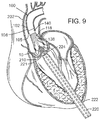
- FIGS. 9-13 are cross-sectional views of a patient's heart illustrating how an exemplary transcatheter heart valve (“THV”) can be deployed to the patient's aortic valve and frictionally secured to the native leaflets using the support structure of FIG. 1 .
- TSV transcatheter heart valve
- FIG. 14 is a perspective view of another exemplary embodiment of a support structure according to the disclosed technology.
- FIG. 15 is a top view of the support structure embodiment shown in FIG. 14
- FIG. 16 is a side view of the support structure embodiment shown in FIG. 14 .
- FIG. 17 is a cross-sectional view of a patient's heart illustrating how a delivery system can operate to deploy the support structure of FIG. 14 to a desired position on the patient's aortic valve.
- FIG. 18 is a cross-sectional view of a patient's heart illustrating how an exemplary THV can be deployed through the aortic arch and into the patient's aortic valve, where it can be frictionally secured to the native leaflets using the support structure of FIG. 14 .
- FIGS. 19-27 are cross-sectional view of a patient's heart illustrating how an exemplary support band can be deployed around the native leaflets of a patient's mitral valve and used to secure a THV to the native leaflets of the mitral valve.
- the support band is deployed using a transapical approach.
- FIG. 28 is a cross-sectional view of a patient's heart illustrating how an exemplary support band as in FIGS. 19-27 can be deployed through the aortic arch.
- FIG. 29 is a top view of an exemplary locking member that can be used to secure portions of a cord of support band material to one another and thereby form a loop.
- FIG. 30 is a top view of another exemplary locking member that can be used to secure portions of a cord of support band material to one another and thereby form a loop.
- FIG. 31 is a perspective view of an exemplary adjustment tool (or pusher tube) that can be used in connection with the locking member of FIG. 30 .
- FIG. 32 is a cross-sectional side view of the exemplary locking member of FIG. 30 .
- FIG. 33 is a cross-sectional side view of the exemplary adjustment tool of FIG. 31 .
- FIGS. 34-37 are cross-sectional views illustrating how the exemplary adjustment tool of FIG. 31 can be used to adjust, lock, and unlock the exemplary locking member of FIG. 30 .
- FIG. 38 is a cross-sectional perspective view of another exemplary locking member that can be used to secure portions of a cord of support band material to one another and thereby form a loop.
- FIG. 39 is a cross-sectional perspective view of an exemplary pusher tube that can be used in connection with the exemplary locking member of FIG. 38 .
- a support structure (sometimes referred to as a “support stent,” “support frame,” “support band,” or “support loop”) that can be used to secure a prosthetic heart valve within a native heart valve.
- a transcatheter heart valve (“THV”)
- THV transcatheter heart valve
- the disclosed support structure and THV can be configured for use with any other heart valve as well.
- exemplary methods and systems for deploying the support structure and corresponding THV are mainly described in connection with replacing an aortic or mitral valve, it should be understood that the disclosed methods and systems can be adapted to deliver a support structure and THV to any heart valve.
- FIG. 1 is a perspective view showing an exemplary embodiment of a support stent or frame 10 .
- Support stent 10 has a generally annular or torroidal body formed from a suitable shape-memory metal or alloy, such as spring steel, Elgiloy®, or Nitinol.
- the material from which the support stent 10 is fabricated allows the support stent to automatically expand to its functional size and shape when deployed but also allows the support stent to be radially compressed to a smaller profile for delivery through the patient's vasculature.
- the stent is not self expanding.
- other mechanisms for expanding the stent can be used (e.g., a balloon catheter).
- the projection of the support stent 10 onto an x-y plane has a generally annular or torroidal shape.
- the illustrated support stent 10 further defines a number of peaks and valleys (or crests and troughs) along its circumference.
- the support stent 10 is sinusoidally shaped in the z direction.
- the support stent 10 is shaped differently in the z direction (e.g., sawtooth-shaped, ringlet-shaped, square-wave shaped, or otherwise shaped to include peaks and valleys).
- the illustrated support stent 10 includes three peaks 20 , 22 , 24 and three valleys 30 , 32 , 34 .
- the peaks 20 , 22 , 24 are positioned above the valleys 30 , 32 , 34 in the z direction.
- the peaks have greater radii than the valleys 30 , 32 , 34 , or vice versa.
- the projection of the support stent 10 onto an x-y plane forms a closed shape having a variable radius (e.g., a starfish shape).
- the size of the support stent 10 can vary from implementation to implementation.
- the support stent 10 is sized such that the support stent can be positioned within the aorta of a patient at a location adjacent to the aortic valve, thereby circumscribing the aortic valve.
- certain embodiments of the support stent 10 have a diameter that is equal to or smaller than the diameter of the prosthetic heart valve when fully expanded.
- the support stent can have an inner or outer diameter between 10 and 50 mm (e.g., between 17 and 28 mm) and a height between 5 and 35 mm (e.g., between 8 and 18 mm).
- the thickness of the annular body of the support stent 10 may vary from embodiment to embodiment, but in certain embodiments is between 0.3 and 1.2 mm.
- FIG. 2 is a perspective view of the exemplary support stent 10 positioned on the surface of an outflow side of a native aortic valve and further illustrates the shape of the support stent.
- the valleys 30 , 32 , 34 of the support stent 10 are shaped so that they can be placed adjacent to commissures 50 , 52 , 54 of the native leaflets 60 , 62 , 64 of the aortic valve.
- the peaks 20 , 22 , 24 are shaped so that they generally approximate or mirror the size and shape of the leaflets 60 , 62 , 64 but are slightly smaller and lower than the height of the leaflets 60 , 62 , 64 at their tips when the aortic valve is fully opened.
- the peaks 20 , 22 , 24 are oriented so that they are adjacent to the commissures 50 , 52 , 54 of the native leaflets 60 , 62 , 64 and the valleys are opposite the apexes of the leaflets 60 , 62 , 64 .
- the support stent 10 can be positioned in any other orientation within the aortic valve as well.
- the shape of the support stent or frame 10 can vary from implementation to implementation.
- the support stent is not sinusoidal or otherwise shaped in the z-plane.
- the support stent is shaped as a cylindrical band or sleeve.
- the support stent or frame can be any shape that defines an interior through which a THV can be inserted, thereby causing the native leaflets of the aortic valve (or other heart valve) to be pinched or securely held between the support stent and the THV.
- the support stent can have a more complex structure.
- the support stent illustrated in FIGS. 1 and 2 is formed from a single annular member (or strut)
- the support stent can comprise multiple annular elements that interlock or are otherwise connected to one another (e.g., via multiple longitudinal members).
- the illustrated support stent 10 also include retaining arms 21 , 23 , 25 that can be used to help position and deploy the support stent 10 into its proper location relative to the native aortic valve.
- the retaining arms 21 , 23 , 25 can have respective apertures 26 , 27 , 28 .
- An exemplary deployment system and procedure for deploying the support stent 10 using the retaining arms 21 , 23 , 25 are described in more detail below.
- the support stent 10 can also have one or more barbs located on its surface. Such barbs allow the support stent 10 to be more securely affixed to the tissue surrounding the stent or the leaflets of the aorta.
- FIGS. 3 and 4 are side views of the distal end portion of an exemplary delivery apparatus 100 for delivering the support stent 10 to its location adjacent the native aortic valve through a patient's vasculature.
- FIG. 3 shows the delivery apparatus when the support stent 10 is in a compressed, predeployed state
- FIG. 4 shows the delivery apparatus when the support stent 10 is in a decompressed, deployed state.
- the delivery apparatus 100 comprises a guide catheter 102 having an elongated shaft 104 , whose distal end 105 is open in the illustrated embodiment.
- the distal end 105 of the guide catheter 102 can be tapered into a conical shape comprising multiple “flaps” forming a protective nose cone that can be urged apart when the support stent 10 and any interior catheters are advanced therethrough.
- the guide catheter 102 is shown as being partially cut away, thus revealing the catheters in its interior.
- a proximal end (not shown) of the guide catheter 102 is connected to a handle of the delivery apparatus 100 .
- the handle can be used by a surgeon to advance and retract the delivery apparatus through the patient's vasculature.
- the delivery apparatus 100 is advanced through the aortic arch of a patient's heart in the retrograde direction after having been percutaneously inserted through the femoral artery.
- the guide catheter can be configured to be selectively steerable or bendable to facilitate advancement of the delivery system 100 through the patient's vasculature.
- An exemplary steerable guide catheter as can be used in embodiments of the disclosed technology is described in detail in U.S. Patent Application Publication No. 2007/0005131 (U.S. patent application Ser. No. 11/152,288), which is hereby expressly incorporated herein by reference.
- the delivery apparatus 100 also includes a stent delivery catheter 108 positioned in the interior of the guide catheter 102 .
- the stent delivery catheter 108 has an elongated shaft 110 and an outer fork 140 connected to a distal end portion of the shaft 110 .
- the shaft 110 of the stent delivery catheter 108 can be configured to be moveable axially relative to the shaft 104 of the guide catheter 102 .
- the shaft 110 of the stent delivery catheter 108 can be sized so that its exterior wall is adjacent to or in contact with the inner wall of the shaft 104 of the guide catheter 102 .
- the delivery apparatus 100 can also include an inner catheter 118 positioned in the interior of the stent deliver catheter 108 .
- the inner catheter 118 can have an elongated shaft 120 and an inner fork 138 secured to the distal end portion of the shaft 120 .
- the shaft 120 of the inner catheter 118 can be configured to be moveable axially relative to the shaft 104 of the guide catheter 102 and relative to the shaft 110 of the stent delivery catheter 108 .
- the shaft 120 of the inner catheter 118 can be sized so that its exterior wall is adjacent to or in contact with the inner wall of the shaft 110 of the stent delivery catheter 108 .
- a guide wire (not shown) can be inserted into the interior of the inner catheter 118 .
- the guide wire can be used, for example, to help ensure proper advancement of the guide catheter 102 and its interior catheters through the vasculature of a patient.
- a stent retaining mechanism is formed from the inner fork 138 attached to the distal end portion of the shaft 120 of the inner catheter 118 and the outer fork 140 attached to the distal end portion of the shaft 110 of the stent delivery catheter 108 .
- the inner fork 138 includes a plurality of flexible inner prongs 141 , 142 , 143 (three in the illustrated embodiment) at is distal end corresponding to the retaining arms 21 , 23 , 25 of the support stent 10 , and a head portion 144 at its proximal end.
- the outer fork 140 includes a plurality of flexible outer prongs 145 , 146 , 147 (three in the illustrated embodiment) at its distal end corresponding to the retaining arms 21 , 23 , 25 of the stent 10 , and a head portion 148 at its proximal end.
- the distal end portions of the outer prongs 145 , 146 , 147 are formed with respective apertures 155 , 156 , 157 sized to receive the retaining arms 21 , 23 , 25 .
- FIG. 6 is a zoomed-in view of one of the retaining arms 21 , 23 , 25 as it interfaces with corresponding prongs of the outer fork 140 and the inner fork 138 .
- retaining arm 21 is shown, though it should be understood that the retaining mechanism is similarly formed for the retaining arms 23 , 25 .
- the distal end portion of the outer prong 145 is formed with the aperture 155 .
- the retaining arm 21 of the stent is inserted through the aperture 155 of the prong 145 of the outer fork and the prong 141 of the inner fork is inserted through the aperture 26 of the retaining arm 21 so as to retain the retaining arm 21 in the aperture 155 .
- the outer prong 145 and the retaining arm 21 can be formed such that when the inner prong 141 is withdrawn from the aperture 26 , the outer prong 145 flexes radially inward (downward in FIG. 7 ) and/or the retaining arm 21 of the support stent flexes radially outward (upward in FIG. 7 ), thereby causing the retaining arm 21 to be removed from the aperture 155 .
- the retaining mechanism formed by the inner fork 138 and the outer fork 140 create a releasable connection with the support stent 10 that is secure enough to retain the support stent to the stent delivery catheter 108 and to allow the user to adjust the position of the support stent after it is deployed.
- the connection between the support stent and the retaining mechanism can be released by retracting the inner fork 138 relative to the outer fork 140 , as further described below.
- the function of the inner fork and the outer fork can be reversed.
- the prongs of the inner fork can be formed with apertures sized to receive the corresponding retaining arms of the support stent and the prongs of the outer fork can be inserted through the apertures of the retaining arms when the retaining arms are placed through the apertures of the prongs of the inner fork.
- the head portion 144 of the inner fork can be connected to the distal end portion of the shaft 120 of the inner catheter 118 .
- the head portion 144 of the inner fork is formed with a plurality of angularly spaced, inwardly biased retaining flanges 154 .
- An end piece of the shaft 120 can be formed as a cylindrical shaft having an annular groove 121 .
- the shaft 120 can have a collar 122 with an outer diameter that is slightly greater than the diameter defined by the inner free ends of the flanges 154 .
- the inner fork 138 can be secured to the end piece by inserting head portion 144 of the inner fork onto the end piece of the shaft 120 until the flanges 154 flex inwardly into the annular groove 121 adjacent the collar 122 , thereby forming a snap-fit connection between the head portion 144 and the shaft 120 .
- the head portion 144 can have a proximal end that engages an annular shoulder 123 of the shaft 120 that is slightly larger in diameter so as to prevent the head portion from sliding longitudinally along the shaft 120 in the proximal direction.
- the head portion 148 of the outer fork can be secured to a distal end portion of the shaft 110 of the stent delivery catheter 108 in a similar manner. As shown in FIG. 5 , the head portion 148 can be formed with a plurality of angularly spaced, inwardly biased retaining flanges 155 .
- An end piece of the shaft 110 can be formed as a cylindrical shaft having an annular groove 111 . On the distal side of the annular groove 111 , the shaft 110 can have a collar 112 with an outer diameter that is slightly greater than the diameter defined by the free ends of the flanges 155 .
- the outer fork 140 can be secured to the end piece of the shaft 110 by inserting the shaft 110 onto the head portion 148 until the flanges flex inwardly into the groove 111 , thereby forming a snap-fit connection between the head portion 148 and the shaft 110 .
- the head portion 148 can have a proximal end that engages an annular shoulder 123 of the shaft 110 that is slightly larger so as to prevent the head portion from sliding longitudinally along the shaft 110 in the proximal direction.
- the support stent 10 is shown in a radially compressed state in the interior of the elongated shaft 104 of the guide catheter 102 .
- the distance along the z axis between a peak and an adjacent valley of the support stent is greater than the distance along the z axis between the peak and the adjacent valley when the support stent is in it uncompressed state.
- the distal end portion of the shaft 104 can also be referred to as a delivery sheath for the stent 10 .
- the prongs of the outer fork 140 and the inner fork 138 of the stent delivery catheter 108 and the inner catheter 118 engage the retaining arms 21 , 23 , 25 of the support stent 10 in the manner described above with respect to FIGS. 5 and 6 .
- the stent delivery catheter 108 and the inner catheter 118 are advanced toward the distal end 105 of the guide catheter 102 using one or more control handles or mechanisms (not shown) located at the proximal end of the guide catheter 102 . This action causes the support stent 10 to be advanced outwardly through the distal end 105 of the guide catheter 102 and expand into its relaxed, uncompressed state (shown, for example, in FIGS. 1 and 2 ).
- FIG. 4 is a perspective view showing the support stent 10 after it has been advanced from the distal end of the guide catheter 102 .
- the support stent 10 now assumes its relaxed, uncompressed shape but remains connected to the outer fork 140 and the inner fork 138 at its retaining arms 21 , 23 , 25 .
- the support stent 10 can be rotated (in the clockwise or counter-clockwise directions) or repositioned (in the proximal and distal directions and/or into a different position in the x-y plane) into a proper orientation adjacent to its intended target area.
- the support stent 10 can be positioned against the upper surfaces of leaflets of the aortic valve in the manner illustrated in FIG.
- a prosthetic valve e.g., a THV
- a transapical approach e.g., through the apex of the heart and through the left ventricle
- the prosthetic valve is secured in place by frictional engagement between the support stent, the native leaflets, and the prosthetic valve.
- the support stent 10 is shaped so that the THV can be positioned in the interior of the support stent along with the native leaflets of the aortic valve. More specifically, the support stent 10 can be shaped such that the native leaflets become trapped or pinched between the support stent 10 and the exterior of the THV when the THV is installed.
- the diameter of the support stent 10 can be equal to or smaller than the maximum diameter of the THV when fully expanded, thus causing the THV to be frictionally fit to the leaflets of the aortic valve and the support stent 10 . This friction fit creates a solid foundation for the THV that is independent of the state or condition of the leaflets in the aortic valve.
- THVs are most commonly used for treating aortic stenosis, a condition in which the leaflets of the aortic valve become hardened with calcium.
- the hardened leaflets typically provide a good support structure for anchoring the THV within the aortic annulus.
- Other conditions may exist, however, in which it is desirable to implant a THV into the aortic valve and which do not result in a hardening of the leaflets of the aortic valve.
- the support stent 10 can be used as a foundation for a THV when treating patients with aortic insufficiency. Aortic insufficiency results when the aortic annulus dilates such that the aortic valve does not close tightly.
- the aortic annulus is larger than normal and would otherwise require a large THV.
- a support stent or frame such as the support stent or frame 10
- a smaller THV can be used, thereby making the THV delivery process easier and safer.
- the use of a support stent protects against displacement of the THV if there is any further dilation of the aortic valve.
- a support stent can be used to secure a THV in any situation in which the aorta or aortic valve may not be in condition to help support the THV and is not limited to cases of aortic insufficiency.
- a support stent 10 can be used in cases in which the aortic annulus is too dilated or in which the leaflets of the aorta are too weak or soft.
- the support stent can be used to create an anchor for the THV, for instance, in cases in which the native leaflet tissue is too soft because of excess collagen in the aorta.
- FIGS. 7-13 illustrate one exemplary procedure for deploying the support stent and securing a THV to the support stent.
- FIGS. 7-8 are cross-sectional views through the left side of a patient's heart showing the acts performed in delivering the support stent 10 through the aortic arch to the aortic valve.
- FIGS. 9-13 are cross-sectional views through the left side of a patient's heart showing the acts performed in deploying a THV 250 and having it engage the support stent 10 .
- the guide catheter 102 is shown partially cut away in FIGS. 7-13 .
- certain details concerning the delivery system of the THV 250 are omitted.
- FIG. 7 shows the guide catheter 102 of the delivery system 100 as it is advanced through the aortic arch 202 into a position near the surface of the outflow side of the aortic valve 210 .
- the delivery system 100 can be inserted through the femoral artery of the patient and advanced into the aorta in the retrograde direction.
- FIG. 7 also shows the stent delivery catheter 108 , the inner catheter 118 , and the support stent 10 .
- the support stent 10 is in its radially compressed, predeployment state.
- the outer fork 140 and the inner fork 138 which couple the radially compressed support stent 10 to the distal ends of the stent delivery catheter 108 and the inner catheter 118 , respectively.
- FIG. 8 shows the support stent 10 after it has been advanced through the distal end of the guide catheter 102 and assumes its final, uncompressed shape in a position above and adjacent to the aortic valve 210 .
- the support stent 10 can also be placed directly on the surface of the outflow side of the aortic valve.
- FIG. 8 shows that the stent delivery catheter 108 and the inner catheter 118 have been advanced though the distal end of the guide catheter 102 , thereby pushing the support stent 10 out of the guide catheter and allowing it to expand into its natural shape.
- the support stent 10 is rotated and positioned as necessary so that the support stent generally circumscribes the aortic valve and so that the peaks of the support stent are aligned with the tips of the natural leaflets of the aortic valve 210 . Therefore, when the THV is inserted and expanded within the aortic valve 210 , the leaflets of the aortic valve will engage at least the majority of the surface in the interior of the support stent 10 . This alignment will create an overall tighter fit between the support stent 10 and the THV.
- the support stent 10 is rotated and positioned as necessary so that the peaks of the support stent 10 are aligned with the commissures or other portions of the aortic valve.
- the position of the guide catheter 102 and the support stent 10 relative to the aortic valve 210 , as well as the position of other elements of the system, can be monitored using radiopaque markers and fluoroscopy, or using other imaging systems such as transesophageal echo, transthoracic echo, intravascular ultrasound imaging (“IVUS”), or an injectable dye that is radiopaque.
- IVUS intravascular ultrasound imaging
- the prongs of the outer fork 140 and the prongs of the inner fork 138 are also seen in FIG. 8 .
- the prongs of the outer fork 140 and the inner fork 138 remain secured to the support stent 10 until the THV is deployed and frictionally engaged to the support stent.
- the inner and outer forks desirably form a connection between the stent 10 and the delivery system that is secure and rigid enough to allow the surgeon to hold the stent 10 at the desired implanted position against the flow of blood while the THV is being implanted.
- the support stent 10 is self-expanding. In other embodiments, however, the support stent may not be self-expanding. In such embodiments, the support stent can be made of a suitable ductile material, such as stainless steel.
- a mechanism for expanding the support stent can be included as part of the delivery system 100 .
- the support stent can be disposed around a balloon of a balloon catheter in a compressed state.
- the balloon catheter can have a shaft that is interior to the inner catheter 118 . Because the stent 10 is not self-expanding, the distal end portion of the guide catheter 102 need not extend over the compressed support stent.
- the support stent, balloon catheter, inner catheter 118 , and stent delivery catheter 108 can be advanced from the distal end of the guide catheter 102 .
- the balloon portion of the balloon catheter can be inflated, causing the support stent to expand.
- the balloon portion can subsequently be deflated and the balloon catheter withdrawn into the delivery system 100 to remove the balloon from the interior of the support stent while the support stent remains connected to the inner catheter for positioning of the support stent.
- the delivery of the support stent otherwise proceeds as in the illustrated embodiment using the self-expanding support stent 10 .
- FIG. 9 shows an introducer sheath 220 passing into the left ventricle through a puncture 222 and over a guidewire 224 that extends upward through the aortic valve 210 .
- the surgeon locates a distal tip 221 of the introducer sheath 220 just to the inflow side of the aortic valve 210 .
- the position of the introducer sheath 220 relative to the aortic valve 210 can be monitored using radiopaque markers and fluoroscopy, or using other imaging systems.
- FIG. 10 shows the advancement of the balloon catheter 230 over the guidewire 224 and through the introducer sheath 220 .
- the THV 250 is located at the aortic annulus and between the native aortic leaflets.
- FIG. 11 also illustrates retraction of the introducer sheath 220 from its more distal position in FIG. 10 .
- Radiopaque markers may be provided on the distal end of the introducer sheath 220 to more accurately determine its position relative to the valve 210 and balloon 232 .
- FIGS. 12-13 show the front third of the support stent 10 and the front of the THV 250 , but do not show the portions of the native heart valve that would be secured by the front of the support stent 10 . It is to be understood, however, that a corresponding leaflet of the native heart valve would be secured between the support stent 10 and the THV 250 .
- the precise positioning of the THV 250 may be accomplished by locating radiopaque markers on its distal and proximal ends.
- the surgeon can adjust the position of the valve 250 by actuating a steering or deflecting mechanism within the balloon catheter 230 .
- the rotational orientation of the valve 250 can be adjusted relative to the cusps and commissures of the native aortic valve by twisting the balloon catheter 230 from its proximal end and observing specific markers on the valve (or balloon catheter) under fluoroscopy.
- One of the coronary ostia 280 opening into one of the sinuses of the ascending aorta is also shown in FIG. 11 , and those of skill in the art will understand that it is important not to occlude the two coronary ostia with the prosthetic valve 250 .
- FIG. 11 shows the THV 250 in its contracted or unexpanded state crimped around the balloon 232 .
- the balloon 232 is expanded to engage the support stent 10 as seen in FIG. 12 .
- the engagement of the support stent 10 to the exterior of the THV 250 pinches the leaflets of the aortic valve between the support stent and the THV 250 , and thereby secures the THV within the annulus of the aortic valve.
- the inner catheter 118 of the delivery system 100 can be retracted, thereby causing the prongs of the inner fork 138 to become disengaged from the retaining arms of the support stent 10 .
- the prongs of the inner fork 138 can be disengaged from the retaining arms by retracting the stent delivery catheter 108 .
- the delivery system 100 can be retracted from the aortic arch and removed from the patient.
- valve 250 can take a variety of different forms and may comprise an expandable stent portion that supports a valve structure.
- the stent portion desirably has sufficient radial strength to hold the valve at the treatment site and to securely engage the support stent 10 . Additional details regarding balloon expandable valve embodiments that can be used in connection with the disclosed technology are described in U.S. Pat. Nos. 6,730,118 and 6,893,460, both of which are hereby expressly incorporated herein by reference.
- the balloon 232 is deflated, and the entire delivery system including the balloon catheter 230 is withdrawn over the guidewire 224 .
- the guidewire 224 can then be withdrawn, followed by the introducer sheath 220 .
- purse-string sutures 260 at the left ventricular apex can be cinched tight and tied to close the puncture.
- FIGS. 14-16 shows another embodiment of a support stent or frame 310 that can be used to help secure a THV into the interior of a native heart valve, such as the aortic valve.
- FIG. 14 is a perspective view of the support stent 310
- FIG. 15 is a top view of the support stent 310
- FIG. 16 is a side view of the support stent 310 .
- support stent 310 has a generally annular or torroidal body formed from a suitable shape-memory metal or alloy, such as spring steel, Elgiloy®, or Nitinol.
- the support stent 310 is also radially compressible to a smaller profile and can self expand when deployed into its functional size and shape. In other embodiments, however, the support stent 310 is not self expanding.
- the support stent 310 includes a generally cylindrical main body portion 320 and a rim portion 330 .
- the support stent 310 can be a mesh structure, which can be formed, for example, from multiple elements in which approximately half of the elements are angled in a first direction and approximately half of the elements are angled in a second direction, thereby creating a criss-cross or diamond-shaped pattern.
- the rim portion 330 has a greater diameter than the main body portion 320 and is formed as an extension at a bottom region of the main body portion that is folded outwardly from the main body portion and back toward a top region of the main body portion.
- the rim portion 330 thus forms a U-shaped rim or lip around the bottom region of the support stent 310 .
- the rim portion 330 is designed to have a diameter that is slightly larger than the walls of the aortic arch that surround the aortic valve.
- the main body portion 320 defines an interior into which an expandable THV can be expanded and which further engages the native leaflets of the aortic valve.
- the main body portion 320 operates in the same manner as the support stent 10 described above and illustrated in FIGS. 1-12 , whereas the rim portion 330 of the support stent 310 operates to secure the support stent in place by engaging the walls of the aorta that surround the aortic valve.
- the support stent 310 further includes retaining arms 321 , 322 , 323 that can be used to help position and deploy the support stent 310 into its proper location relative to the native aortic valve.
- the retaining arms 321 , 322 , 323 can have respective apertures 326 , 327 , 328 .
- the retaining arms 321 , 322 , 323 are constructed and function in a similar manner as retaining arms 21 , 23 , 25 described above in the embodiment illustrated in FIGS. 1-12 .
- FIGS. 17-18 illustrate one exemplary procedure for deploying the support stent 310 and securing a THV 340 within an interior of the support stent.
- FIGS. 17-18 are cross-sectional views through the left side of a patient's heart showing the acts performed in delivering the support stent 310 through the aortic arch to the aortic valve.
- certain details concerning the delivery system of the THV 340 are omitted. Additional details and alternative embodiments of the delivery system for the THV 340 that may be used with the support stent described herein are discussed in U.S. Patent Application Publication No. 2008/0065011 (U.S. application Ser. No. 11/852,977) and U.S. Patent Application Publication No. 2007/0005131 (U.S. application Ser. No. 11/152,288), which are hereby expressly incorporated herein by reference.
- FIG. 17 shows an outer catheter 352 (which can be a guide catheter) of a delivery system 350 as it is advanced through the aortic arch 302 into a position near the surface of the outflow side of the aortic valve 304 .
- the delivery system 350 can be inserted through the femoral artery of the patient and advanced into the aorta in the retrograde direction.
- FIG. 17 also shows a stent delivery catheter 354 , an inner catheter 356 , and the support stent 310 . Also seen in FIG. 17 are the outer fork 360 and the inner fork 362 , which couple the support stent 310 to the distal ends of the stent delivery catheter 354 and the inner catheter 356 , respectively.
- FIG. 17 shows the support stent 310 after it has been advanced through the distal end of the guide catheter 352 and assumes its final, uncompressed shape in a position adjacent to the aortic valve 304 .
- FIGS. 17-18 do not show the entire front side of the support stent 310 or the corresponding valve leaflet that would be secured by the front side of the support stent 310 . It is to be understood, however, that in practice the entire support stent 310 would exist and engage a corresponding leaflet of the native heart valve.
- the support stent 310 can be positioned adjacent to the aortic valve 304 so that the rim portion 330 of the support stent engages the walls surrounding the aortic valve 304 and exerts an outward force against those walls, thereby securing the support stent 310 within the aorta.
- This positioning can be achieved, for example, by advancing the guide catheter 352 to a position directly adjacent the aortic valve 304 while the stent delivery catheter 354 and the inner catheter 356 are undeployed and while the support stent 310 remains in its compressed state.
- the guide catheter 352 can then be retracted while the stent delivery catheter 354 and the inner catheter 356 are held in place, thereby allowing the support stent 310 to expand toward its natural shape.
- the position of the guide catheter 352 and the support stent 310 relative to the aortic valve 304 can be monitored using radiopaque markers and fluoroscopy, or using other imaging systems such as transesophageal echo, transthoracic echo, IVUS, or an injectable dye that is radiopaque.
- the prongs of the inner fork 362 can be disengaged from the corresponding apertures of the retaining arms of the support stent 310 .
- the inner catheter 356 can be retracted into the interior of the stent delivery catheter 354 , thereby releasing the support stent 310 from the outer fork 360 and the inner fork 362 .
- the delivery system 350 can then be retracted from the aorta and removed from the patient's body.
- a THV (such as any of the THVs discussed above) can be introduced.
- a delivery system having a delivery catheter that is advanced through the patient's aorta can be used to deliver the THV.
- a transfemoral approach can be used.
- any of the exemplary systems and methods described in U.S. Patent Application Publication No. 2008/0065011 (U.S. application Ser. No. 11/852,977) or U.S. Patent Application Publication No. 2007/0005131 (U.S. application Ser. No. 11/152,288) can be used with the support stent 310 .
- the transapical approach shown in FIGS. 7-13 can be used.
- FIG. 18 shows delivery system 380 comprising an outer catheter 382 (which can be a guide catheter) and a balloon catheter 390 extending through the guide catheter.
- the balloon catheter 390 has a balloon at its distal end on which the THV is mounted.
- the delivery system 380 can be inserted through the femoral artery of the patient and advanced into the aorta in the retrograde direction.
- FIG. 18 further shows a guidewire 392 that has been first inserted into the patient's vasculature and advanced into the left ventricle. The delivery system can then be inserted into the body and advanced over the guidewire 392 until the THV is positioned within the interior of the aortic valve.
- the THV is not only in the interior of the aortic valve 304 but also in the interior of the main body portion of the support stent 310 .
- FIG. 18 shows the THV 340 in its contracted (or unexpanded) state crimped around the balloon portion of the balloon catheter 390 .
- the balloon of the balloon catheter 390 can be expanded such that the THV 340 expands and urges the native leaflets of the aortic valve against the support stent 310 , thereby securing the THV within the annulus of the aortic valve.
- the balloon of the balloon catheter 390 is deflated, and the entire delivery system 380 including the balloon catheter is withdrawn over the guidewire 392 . The guidewire 392 can then be withdrawn.
- a support stent and THV are delivered surgically to the desired heart valve (e.g., in an open-heart surgical procedure).
- the support stent and THV are delivered surgically, non-compressible support stents and/or THVs are used.
- the mitral valve can also suffer from valve insufficiency, which may be desirably treated through the implantation of a prosthetic valve.
- mitral valve insufficiency often causes the valve annulus to be dilated and the valve leaflets to be too soft to provide reliable support for securing a prosthetic valve.
- TSV transcatheter heart valve
- the mitral valve support structure is desirably positioned on the outflow side of the mitral valve.
- the THV can be inserted into the interiors of the native mitral valve and the support structure and then expanded such that the mitral valve leaflets are frictionally engaged between the exterior surface of the THV and the interior surface of the support structure.
- the support structure can be deployed after the THV is positioned and expanded within the mitral valve. The diameter of the support structure can then be adjusted such that the valve leaflets are frictionally engaged against the exterior of the THV.
- a support structure to secure the THV a smaller THV can be used, thereby making the THV delivery process easier and safer.
- the use of a support structure protects against displacement of the THV if there is any further dilation of the aortic valve.
- the native leaflets function as a sealing ring around the valve that prevents paravalvular leaks.
- the support structure for the mitral valve can have a variety of shapes.
- the support structure has a sinusoidal shape as with the support stent 110 , but in other embodiments does not have a sinusoidal shape or is not otherwise shaped in the z-plane.
- the support stent is shaped as a cylindrical band or sleeve.
- the support frame can also have a more complex structure. In general, any of the shapes and materials used for embodiments of the aortic valve support structures described above can be used for embodiments of the mitral valve support structures and vice versa.
- the mitral valve support structure is made of a suitable biocompatible material that can be delivered through one or more delivery catheters and formed into a band or loop. For this reason, the structure is sometimes referred to herein as a “support band” or “support loop.”
- the biocompatible material may comprise, for example, nylon, silk, polyester, or other synthetic biocompatible material.
- the biocompatible material may alternatively comprise a natural material, such as catgut.
- the support structure is formed of a biocompatible shape-memory metal or alloy, such as spring steel, Elgiloy®, or Nitinol.
- FIGS. 19-27 show one exemplary procedure for delivering a support structure to the mitral valve and having it secure a THV into its desired position within the mitral valve.
- FIGS. 19-24 are cross-sectional views through the left side of a patient's heart showing the acts performed in delivering the support structure using a transapical approach.
- FIGS. 25-27 are cross-sectional views through the left side of a patient's heart showing the acts performed in deploying a THV and having it engage the mitral valve leaflets and the interior of the support structure. It should be noted that FIGS. 19-27 are schematic in nature and thus do not necessarily depict a precise representation of the delivery process.
- the patient's ribcage is not shown for illustrative purposes and the size of the sheaths used with the delivery system have been altered somewhat in order to better illustrate the procedure.
- One of ordinary skill in the art will readily understand the range and types of sheaths and catheters that can be used to implement the depicted procedure.
- FIG. 19 shows an introducer sheath 400 inserted into the left ventricle of a patient's heart through a puncture 402 .
- the introducer sheath 400 is positioned so that it is not directly centered about the outflow side of the mitral valve, but rather is offset from the center.
- the introducer sheath 400 can be positioned so that it is on the exterior side of the space enclosed by chordae tendineae 412 . It should be noted that in FIGS. 19-27 , the chordae tendineae 412 of the left ventricle are only partially shown.
- chordae tendineae 412 are respectively attached to each of the mitral valve leaflets and to the papillary muscles of the left ventricle.
- a surgeon can locate a distal tip 401 of the introducer sheath 400 near the outflow side of the mitral valve (e.g., within 1-10 millimeters).
- FIG. 20 shows a first catheter delivery sheath 420 and a second catheter delivery sheath 422 being advanced through the interior of the introducer sheath 400 .
- the introducer sheath 400 can define two or more separate lumens through which the first and the second catheter delivery sheaths 420 , 422 can be inserted or can define a single lumen sufficiently large to receive both the first and the second catheter delivery sheaths 420 , 422 .
- the first and second catheter delivery sheaths 420 , 422 can be shaped so that they arc outwardly from each other when advanced out of the distal tip 401 of the introducer sheath 400 .
- the first and second catheter delivery sheaths 420 , 422 have end regions 421 , 423 that arch about 90 degrees (or some other amount, such as between 45-90 degrees) when they are in their natural state.
- the amount of arching may vary from implementation to implementation but is desirably selected so that the tips of the end portions 421 , 423 are in approximately the same plane.
- the catheter delivery sheaths 420 , 422 are not used as part of the support structure delivery procedure.
- a first loop delivery catheter 430 is advanced through the interior of the first catheter delivery sheath 420 and extended substantially around the exterior of one half of the chordae tendineae (e.g., the medial half of the chordae tendineae).
- a second loop deliver catheter 432 is advanced through the interior of the second catheter delivery sheath 422 and extended substantially around the exterior of the other half of the chordae tendineae (e.g., the lateral half of the chordae tendineae).
- the loop delivery catheters 430 , 432 can be steerable catheters having end regions that can be selectively deformed or arched by an operator. Such steerable catheters are well known in the art.
- the loop delivery catheters 420 , 432 can additionally be magnetic or have magnetic distal end portions.
- the first loop delivery catheter 430 has a magnetic distal end portion 431 with a first polarity
- the second loop delivery catheter 432 has a magnetic distal end portion 433 with a second polarity opposite the first polarity.
- the end portions 431 , 433 are attracted to one another and will form a contiguous junction when in sufficient proximity to each other.
- Other mechanisms for engaging the end portions 431 , 433 to one another are also possible (e.g., a hook mechanism, an adhesive, an enlarged diameter of one end portion, and other such mechanisms).
- the first and the second loop delivery catheters 430 , 432 form a single interior or lumen through which a support band material can be advanced. Furthermore, when the end portions 431 , 433 are engaged to one another, the first and the second loop delivery catheters 430 , 432 create a partial loop that circumscribes the chordae tendineae.
- FIG. 22 shows the magnetic distal end portions 431 , 433 after the first and second loop delivery catheters 430 , 432 are arched around the chordae tendineae and after the distal end portions have been magnetically engaged to one another.
- a cord 440 of biocompatible material can be advanced through the interior of one of the loop delivery catheters 430 , 432 and into the interior of the other one of the loop delivery catheters.
- the term “cord” refers to a slender length of material that can be formed from a single strand, fiber, or filament, or can comprise multiple strands, fibers, or filaments.
- an end 442 of the cord 440 can be advanced from a proximal end of the first loop delivery catheter 430 , through the interior of the first loop delivery catheter, through the junction formed by the distal end portions 431 , 433 , and through the interior of the second loop delivery catheter 432 until it appears on the proximate end of the second loop delivery catheter 432 .
- the cord 440 is a guidewire (e.g., a guidewire made of stainless steel or other suitable metal).
- the guidewire can then be attached to another cord of biocompatible material used to form the support band and pulled through the interior of the first and the second loop delivery catheters 430 , 432 , thereby positioning the cord of biocompatible material around the chordae tendineae in a partial loop.
- the first and second loop delivery catheters 430 , 432 and the first and second catheter delivery sheaths 420 , 422 can be retracted from the introducer sheath 400 .
- FIG. 23 shows a cord 443 of biocompatible material used to form the support band positioned around the chordae tendineae after the first and second loop delivery catheters 430 , 432 and the first and second catheter delivery sheaths 430 , 422 have been withdrawn.
- a sheath 450 is inserted over both ends of the cord 443 and over a first portion 444 and a second portion 446 of the cord 443 , which run through the length of the sheath 450 .
- a locking member 460 can be advanced over the first and second portions 444 , 446 of the cord 443 and into the left ventricle.
- the locking member 460 can be advanced, for example, by a pusher tube 462 that pushes the locking member 460 over the portions 444 , 446 of the cord 440 .
- the locking member 460 includes lumens or other openings configured to receive each of the two portions 444 , 446 and permits movement along the portions 444 , 446 in only a single direction.
- the locking member 460 can be unlocked from the portions 444 , 446 of the cord 440 and advanced in both directions along the cord 440 .
- the pusher tube 462 is further configured to sever the portions of the cord 440 that extend through a proximal side of the locking member 460 , thereby releasing a support band 441 formed by the locking member 460 and the loop-shaped portion of the cord 443 from the pusher tube 462 .
- the pusher tube 462 can further be formed of a shape memory material or include a deflection mechanism that allows the pusher tube to have an arched shape toward its distal end.
- the pusher tube 462 can be used to better position the support band 441 formed by the loop-shaped portion of the cord 443 and the locking member 460 adjacent to the outflow side of the mitral valve such that the native leaflets of the mitral valve open into an interior of the support band 441 .
- the sheath 450 can be withdrawn from the introducer sheath 400 once the locking member 460 and the pusher tube 462 are advanced into the left ventricle.
- a balloon catheter 470 can be advanced through the introducer sheath 400 and into the interior of the mitral valve 410 of the patient. Although not shown in the illustrated embodiment, the balloon catheter may be guided by a guidewire into the center of the mitral valve.
- a balloon portion 472 of the balloon catheter 470 around which a THV 480 is crimped can be located within the mitral annulus.
- Radiopaque markers or other imaging enhancers may be provided on the distal end of the introducer sheath 400 and the balloon catheter 470 to more accurately determine the position of the THV 480 relative to the native valve 410 .
- a surgeon can adjust the position of the THV 480 by actuating a steering or deflecting mechanism within the balloon catheter 470 .
- the locking member 460 and the pusher tube 462 can be positioned so as not to interfere with the balloon catheter 470 . Furthermore, with the THV 480 properly positioned within the mitral valve 410 , the pusher tube 462 can be used to position the support band 441 formed by the loop-shaped remaining portion of the cord 443 around the native valve leaflets of the mitral valve. Radiopaque markers or other suitable imaging enhancers can be provided on the pusher tube 462 , the locking member 460 , and/or the loop-portion of the cord to allow for the proper positioning of the support band 441 relative to the valve leaflets.
- the balloon portion 472 of the balloon catheter 470 can be inflated, thereby expanding the THV 480 against the native valve leaflets and causing the leaflets to frictionally engage the interior surface of the support band 441 .
- This expansion secures the THV 480 to the native valve leaflets.
- the expansion pinches the native leaflets of the mitral valve between the support band 441 and the THV 480 , and thereby secures the THV within the annulus of the mitral valve.
- the balloon portion 472 of the balloon catheter 470 can be deflated and the balloon catheter withdrawn from the introducer sheath 400 .
- the pusher tube 462 can then be disengaged from the loop 441 .
- the pusher tube 462 can comprise a cutting element at its distal end that can be activated by the surgeon from the proximal end. An example of one suitable cutting element is shown below with respect to FIG. 39 .
- a separate cutting device e.g., a cutting catheter or catheter having a controllable cutting element
- a separate cutting device can be inserted through the introducer sheath 400 and used to cut the portions of the cord 443 that extend through the proximal side of the locking member 460 and do not form part of the support band 441 .
- FIG. 27 shows the THV 480 secured within the native mitral valve after the support band 441 has been released from the pusher tube 462 and the pusher tube has been retracted from the introducer sheath 400 .
- the THV 480 can take a variety of different forms and may comprise an expandable stent portion that supports a valve structure.
- the stent portion desirably has sufficient radial strength to hold the valve at the treatment site and to securely engage the support band 441 .
- the THV is delivered and expanded into the mitral valve before the support band is delivered to the left ventricle.
- the THV can be temporarily secured within the mitral valve.
- the THV can be temporarily secured to the mitral valve using one or more anchoring members on the exterior of the THV (e.g., anchoring members having a main body and one or more hook-shaped or umbrella-shaped barbs).
- the THV can also be temporarily secured within the mitral valve through the use of one or more spring-loaded clamps, rivets, clasps, or other such fastening mechanisms.
- the support band With the THV temporarily secured, the support band can be delivered around the native leaflets as described above and the diameter of the support band reduced until a desired frictional fit is created between the support band, the leaflets, and the THV. Any of the locking members described herein that allow the diameter of the support band to be adjusted can be used to achieve the desired diameter.
- FIG. 28 shows an example of such a delivery system 500 .
- FIG. 28 shows the delivery system 500 after a delivery catheter has been advanced through the aortic arch to a position adjacent the aortic valve and as a first loop deliver catheter 510 and a second loop deliver catheter 512 are deployed through the distal end of a delivery catheter 502 .
- the first and second loop delivery catheters 510 , 512 can be steerable and comprise magnetic distal end portions that allow the catheters 510 , 512 to engage one another on a distal side of the chordae tendineae, thereby forming a delivery lumen through which biocompatible material for the support band or loop can be deployed.
- FIG. 28 Also shown in FIG. 28 is an introducer sheath 520 and a balloon delivery catheter 522 for deploying a THV 524 .
- the delivery procedure can otherwise be substantially similar or identical to the procedure shown in FIGS. 19-27 .
- the support band may be formed of a shape-memory material that assumes a C-shape when not acted on by any external forces.
- the support band can be further configured such that one end of the C-shaped member is hollow and has a slightly larger diameter than the opposite end.
- the support band can be stretched into a linear form and advanced through a delivery catheter (e.g., using a pusher element).
- the distal end of the delivery catheter can be positioned adjacent the chordae tendineae such that when the support band is advanced out of the distal end, it wraps around the chordae tendineae.
- a clamping device that is designed to engage the C-shaped support band and urge the ends of the support band together can be inserted into the heart (e.g., through the delivery catheter, the introducer sheath, or through a separate catheter).
- the clamping device can be used to urge one end of the support band into the hollow opposite end of the band.
- the ends can be crimped so that the support band forms a ring-shaped support band (e.g., using the clamping device or other device).
- the hollow end of the support band can comprise a shoulder that engages an angled collar on the other end of the support band when the ends are urged together, thereby form a snap-fit connection.
- the support band With the ends of the support band secured to one another, the support band can be positioned around the native leaflets of the mitral valve (e.g., using the clamping device or other positioning device) as a balloon catheter delivers a THV. Upon expansion, the THV will pinch the native valve leaflets between the outer surface of the THV and the interior surface of the support band, thereby securing the THV within the mitral valve.
- the support band includes one or more clamping or fastening devices that can be used to clamp or fasten the support band to the native leaflets of the mitral leaflets.
- the clamping or fastening devices can comprise spring-loaded clamps, anchoring members having one or more hook or umbrella-shaped barbs, clasps, or other such clamping or fastening mechanisms.
- the support band still has a substantially fixed diameter such that when the THV is expanded into the interior of the mitral valve, the THV causes the native valve leaflets to be pinched against the interior surface of the support band, thereby securing the THV within the mitral valve.
- the THV itself can include one or more clamping or fastening devices designed to clamp or fasten the THV to the native leaflets of the mitral valve (e.g., any of the clamping or fastening mechanisms described above).
- the THV can be secured directly to the native leaflets without the use of a support band or other support structure.
- FIG. 29 shows one exemplary embodiment of a locking member that can be used for locking member 460 shown in FIGS. 19-27 .
- locking member 600 which can be a clamp, such as an adjustable, C-shaped clamp with interlocking teeth around a portion of the clamp.
- the locking member 600 has two arms 610 , 612 , each formed with interlocking teeth 620 , 622 .
- Interlocking teeth 620 , 622 are configured to lock the clamp in one or more positions of varying circumference when pressure is applied to the two arms 610 , 612 and pushes the arms together.
- the cord portions (such as portions 446 , 446 ) can be inserted into the interior 630 of the locking member 600 .
- the arms 610 , 612 can be pushed together and tightened so that the portions 444 , 446 are secured in place (e.g., using a clamping device inserted into the left ventricle through the introducer sheath or using the pusher tube 462 modified to include a clamping mechanism).
- the interior 630 can additionally have grooves to increase the friction and decrease the slippage between the locking member 600 and the portions of the cord secured therein.
- FIGS. 30-37 depict another exemplary embodiment of a locking member that can be used for locking member 460 shown in FIGS. 19-27 .
- FIGS. 30-37 show an adjustable locking member 700 , which can be attached to two portions of a cord, thereby forming the support band.
- the adjustable locking member 700 comprises a tapered, plastic pin 710 that fits into a tapered, plastic snap ring 720 .
- pin 710 and ring 720 are locked together, the adjustable locking member 700 is prevented from moving relative to the portions of the cord that are captured within the adjustable locking member 700 (e.g., cord portions 702 , 704 in FIG. 30 ).
- FIG. 31 illustrates an exemplary pusher tube (or adjustment catheter) 730 that can be used to introduce, position, and lock the adjustable locking member 700 in a desired position.
- the exemplary pusher tube 730 in the illustrated configuration has a fork member 732 , an unlocking push member 734 that is extendable through the fork member 732 , and a locking push member 736 that is extendable over the unlocking push member 734 .
- Fork member 732 is configured so that it can move the adjustable locking member 700 over the cord portions to which it is connected.
- fork member 732 can engage the adjustable locking member 700 when it is positioned along the cord portions (but not yet in a locked position) such that by moving the pusher tube 730 in one direction along the length of the cord portions, adjustable locking member 700 is also moved. By moving the adjustable locking member 700 in this manner, the effective diameter of the support band formed by the cord and the adjustable locking member 700 can be modified.
- Push members 734 , 736 are slidably movable relative to each other and the fork member 732 to effect locking and unlocking of the adjustable locking member 700 , as further described below.
- the unlocking push member 734 unlocks the adjustable locking member 700 from the locked position and the locking push member 736 locks the adjustable locking member 700 from the unlocked position.
- FIG. 32 depicts the adjustable locking member 700 , according to one embodiment, in more detail.
- the pin 710 comprises pin slots or holes 712 (which accept the cord portions) and locking members or flanges 714 (which extend outward to secure the pin to the ring in a locked position).
- Ring 720 comprises ring slots or holes 722 (which accepts the cord portions) and pin receiving hole 724 (which receives the pin to secure the pin to the ring in a locked position).
- the locking members 714 are deformable to allow the pin member to be inserted throughout ring member and form a snap-fit connection sufficient to hold the ring member on the pin member.
- FIGS. 33-37 depict the relationship between the adjustable locking member 700 and the pusher tube 730 , according to one embodiment, and their functions relative to one another.
- the pusher tube 730 comprises fork member 732 , unlocking push member 734 , and locking push member 736 .
- FIG. 33 shows the pusher tube 730 in more detail. Both the unlocking push member 734 and the locking push member 736 are slidably movable within the pusher tube 730 along the longitudinal direction identified by the arrows shown in FIG. 33 .
- the unlocking push member 734 is desirably a solid member that is sized to fit within the locking push member 736 , which is desirably cylindrical with a longitudinally extending hollow section or lumen for receiving the unlocking push member 734 .
- FIG. 34 shows the adjustable locking member 700 with the pin 710 and the ring 720 locked together.
- the cord portions 702 , 704 pass inside the ring 720 and around the pin 710 (through the ring holes and pin holes) and are captured between these two components.
- the cord portions 702 , 704 are held in place relative to each other, and the pin 710 and the ring 720 are held in place relative to the cord portions 702 , 704 by the friction created at the surface interfaces.
- the fork member 732 is inserted between the pin 710 and the ring 720 , and the unlocking push member 734 is extended from the pusher tube 730 to push the pin 710 and the ring 720 apart.
- the fork member 732 holds the ring 720 in place, while the unlocking push member 734 applies longitudinal pressure against the tip of the pin 710 , forcing it out of the ring 720 .
- the unlocking push member 734 is desirably sized so that it can fit at least partially through the pin receiving hole 724 to assist in unlocking the pin 710 and the ring 720 from one another.
- the fork member 732 is placed at the far (distal) end of the pin 710 and the locking push member 736 is extended from the pusher tube 730 .
- the locking push member 736 is configured with a cylindrical surface that is sized to mate with the area of the ring 720 that surrounds the pin receiving hole. While the fork member 732 holds the pin 710 in place, the locking push member 736 forces the ring 720 onto the pin 710 and locks the pin and the ring together.
- the frictional engagement of the adjustable locking member with the cord portions maintains the position of the adjustable locking member relative to the cord portions 702 , 704 .
- the three-point connection system described above permits a surgeon to perform fine adjustments of the diameter of the support band around the chordae tendineae and around the outflow side of the native leaflets of the mitral valve.
- FIGS. 38-39 depict another exemplary embodiment of a locking member that can be used for locking member 460 shown in FIGS. 19-27 .
- FIG. 38 shows an adjustable locking member 900 having a generally cylindrical body with two lumens (or apertures) 910 , 912 formed therein that extend from a top surface 902 to a bottom surface 904 of the body.
- the interior of the lumens 910 , 912 comprises a plurality of teeth (or collars) 920 , 922 that are angled toward the bottom surface 904 .
- the teeth 920 can have some flexibility and be formed to allow a cord portion, such as cord portion 930 or cord portion 932 , to slide through the lumens 910 , 912 in a first direction, but not in an opposite second direction.
- the teeth 920 , 922 of the adjustable locking member 900 allow for one-way movement of the locking member 900 along the cord portions 930 , 932 .
- the adjustable locking member 900 can be used to securely form the support band and allows for the diameter of the support band to be adjusted to its desired size.
- FIG. 39 shows an exemplary embodiment of a pusher tube 950 that can be used with the adjustable locking member 900 (e.g., the pusher tube 950 can be used as the pusher tube 462 shown in FIGS. 19-27 ).
- the exemplary pusher tube 950 includes lumens 960 , 962 through which the cord portions 930 , 932 can extend.
- the lumens 960 , 962 have a sufficiently large diameter and a smooth interior that allows the cord portions 930 , 932 to more easily slide therethrough.
- the pusher tube 950 further includes a rotatable blade 970 at its distal end 902 .
- the rotatable blade 970 can be rotatable about a central axis of the pusher tube 950 and connected to an interior rod member 972 that extends through a central lumen of the pusher tube 950 .
- a handle (not shown) can be attached to the interior rod member 972 at its proximal end and allow for an operator to manually rotate the rotatable blade 970 in order to sever the pusher tube 950 from the adjustable locking member 900 .
- a support band and THV are delivered surgically to the desired heart valve (e.g., in an open-heart surgical procedure).
- the support band and THV are delivered surgically, non-compressible THVs are used.
Landscapes
- Health & Medical Sciences (AREA)
- Cardiology (AREA)
- Engineering & Computer Science (AREA)
- Biomedical Technology (AREA)
- Heart & Thoracic Surgery (AREA)
- Transplantation (AREA)
- Oral & Maxillofacial Surgery (AREA)
- Vascular Medicine (AREA)
- Life Sciences & Earth Sciences (AREA)
- Animal Behavior & Ethology (AREA)
- General Health & Medical Sciences (AREA)
- Public Health (AREA)
- Veterinary Medicine (AREA)
- Mechanical Engineering (AREA)
- Prostheses (AREA)
Abstract
Description
Claims (13)
Priority Applications (4)
| Application Number | Priority Date | Filing Date | Title |
|---|---|---|---|
| US15/729,986 US10722355B2 (en) | 2008-06-20 | 2017-10-11 | Retaining mechanisms for prosthetic valves |
| US16/283,637 US10966827B2 (en) | 2008-06-20 | 2019-02-22 | Retaining mechanisms for prosthetic valves |
| US17/220,818 US20210220132A1 (en) | 2008-06-20 | 2021-04-01 | Retaining mechanisms for prosthetic valves |
| US18/350,555 US20230346552A1 (en) | 2008-06-20 | 2023-07-11 | Methods for treating a deficient native mitral valve |
Applications Claiming Priority (7)
| Application Number | Priority Date | Filing Date | Title |
|---|---|---|---|
| US7459708P | 2008-06-20 | 2008-06-20 | |
| US8894708P | 2008-08-14 | 2008-08-14 | |
| US12/368,891 US8323335B2 (en) | 2008-06-20 | 2009-02-10 | Retaining mechanisms for prosthetic valves and methods for using |
| US13/687,960 US8597348B2 (en) | 2008-06-20 | 2012-11-28 | Retaining mechanisms for prosthetic valves |
| US14/091,239 US9561101B2 (en) | 2008-06-20 | 2013-11-26 | Two-part prosthetic valve system |
| US15/130,433 US9993338B2 (en) | 2008-06-20 | 2016-04-15 | Methods for retaining a prosthetic heart valve |
| US15/729,986 US10722355B2 (en) | 2008-06-20 | 2017-10-11 | Retaining mechanisms for prosthetic valves |
Related Parent Applications (1)
| Application Number | Title | Priority Date | Filing Date |
|---|---|---|---|
| US15/130,433 Continuation US9993338B2 (en) | 2008-06-20 | 2016-04-15 | Methods for retaining a prosthetic heart valve |
Related Child Applications (1)
| Application Number | Title | Priority Date | Filing Date |
|---|---|---|---|
| US16/283,637 Continuation US10966827B2 (en) | 2008-06-20 | 2019-02-22 | Retaining mechanisms for prosthetic valves |
Publications (2)
| Publication Number | Publication Date |
|---|---|
| US20180028313A1 US20180028313A1 (en) | 2018-02-01 |
| US10722355B2 true US10722355B2 (en) | 2020-07-28 |
Family
ID=41434723
Family Applications (9)
| Application Number | Title | Priority Date | Filing Date |
|---|---|---|---|
| US12/368,891 Active 2030-09-08 US8323335B2 (en) | 2008-06-20 | 2009-02-10 | Retaining mechanisms for prosthetic valves and methods for using |
| US12/818,498 Active 2029-03-05 US8236049B2 (en) | 2008-06-20 | 2010-06-18 | Multipiece prosthetic mitral valve and method |
| US13/687,960 Active US8597348B2 (en) | 2008-06-20 | 2012-11-28 | Retaining mechanisms for prosthetic valves |
| US14/091,239 Active 2029-05-07 US9561101B2 (en) | 2008-06-20 | 2013-11-26 | Two-part prosthetic valve system |
| US15/130,433 Active 2029-03-12 US9993338B2 (en) | 2008-06-20 | 2016-04-15 | Methods for retaining a prosthetic heart valve |
| US15/729,986 Active 2029-12-07 US10722355B2 (en) | 2008-06-20 | 2017-10-11 | Retaining mechanisms for prosthetic valves |
| US16/283,637 Active 2029-06-15 US10966827B2 (en) | 2008-06-20 | 2019-02-22 | Retaining mechanisms for prosthetic valves |
| US17/220,818 Pending US20210220132A1 (en) | 2008-06-20 | 2021-04-01 | Retaining mechanisms for prosthetic valves |
| US18/350,555 Pending US20230346552A1 (en) | 2008-06-20 | 2023-07-11 | Methods for treating a deficient native mitral valve |
Family Applications Before (5)
| Application Number | Title | Priority Date | Filing Date |
|---|---|---|---|
| US12/368,891 Active 2030-09-08 US8323335B2 (en) | 2008-06-20 | 2009-02-10 | Retaining mechanisms for prosthetic valves and methods for using |
| US12/818,498 Active 2029-03-05 US8236049B2 (en) | 2008-06-20 | 2010-06-18 | Multipiece prosthetic mitral valve and method |
| US13/687,960 Active US8597348B2 (en) | 2008-06-20 | 2012-11-28 | Retaining mechanisms for prosthetic valves |
| US14/091,239 Active 2029-05-07 US9561101B2 (en) | 2008-06-20 | 2013-11-26 | Two-part prosthetic valve system |
| US15/130,433 Active 2029-03-12 US9993338B2 (en) | 2008-06-20 | 2016-04-15 | Methods for retaining a prosthetic heart valve |
Family Applications After (3)
| Application Number | Title | Priority Date | Filing Date |
|---|---|---|---|
| US16/283,637 Active 2029-06-15 US10966827B2 (en) | 2008-06-20 | 2019-02-22 | Retaining mechanisms for prosthetic valves |
| US17/220,818 Pending US20210220132A1 (en) | 2008-06-20 | 2021-04-01 | Retaining mechanisms for prosthetic valves |
| US18/350,555 Pending US20230346552A1 (en) | 2008-06-20 | 2023-07-11 | Methods for treating a deficient native mitral valve |
Country Status (13)
| Country | Link |
|---|---|
| US (9) | US8323335B2 (en) |
| EP (3) | EP3311775B1 (en) |
| AU (1) | AU2009259863B2 (en) |
| CA (3) | CA2728273C (en) |
| DK (1) | DK3311775T3 (en) |
| ES (1) | ES2952030T3 (en) |
| FI (1) | FI3311775T3 (en) |
| HR (1) | HRP20230651T1 (en) |
| HU (1) | HUE062595T2 (en) |
| PL (1) | PL3311775T3 (en) |
| PT (1) | PT3311775T (en) |
| SI (1) | SI3311775T1 (en) |
| WO (1) | WO2009155561A2 (en) |
Cited By (1)
| Publication number | Priority date | Publication date | Assignee | Title |
|---|---|---|---|---|
| US10966827B2 (en) * | 2008-06-20 | 2021-04-06 | Edwards Lifesciences Corporation | Retaining mechanisms for prosthetic valves |
Families Citing this family (527)
| Publication number | Priority date | Publication date | Assignee | Title |
|---|---|---|---|---|
| EP0850607A1 (en) | 1996-12-31 | 1998-07-01 | Cordis Corporation | Valve prosthesis for implantation in body channels |
| US6454799B1 (en) | 2000-04-06 | 2002-09-24 | Edwards Lifesciences Corporation | Minimally-invasive heart valves and methods of use |
| WO2002015793A2 (en) | 2000-08-18 | 2002-02-28 | Atritech, Inc. | Expandable implant devices for filtering blood flow from atrial appendages |
| US6733525B2 (en) | 2001-03-23 | 2004-05-11 | Edwards Lifesciences Corporation | Rolled minimally-invasive heart valves and methods of use |
| US7556646B2 (en) | 2001-09-13 | 2009-07-07 | Edwards Lifesciences Corporation | Methods and apparatuses for deploying minimally-invasive heart valves |
| US6893460B2 (en) | 2001-10-11 | 2005-05-17 | Percutaneous Valve Technologies Inc. | Implantable prosthetic valve |
| US8308797B2 (en) | 2002-01-04 | 2012-11-13 | Colibri Heart Valve, LLC | Percutaneously implantable replacement heart valve device and method of making same |
| US8758372B2 (en) | 2002-08-29 | 2014-06-24 | St. Jude Medical, Cardiology Division, Inc. | Implantable devices for controlling the size and shape of an anatomical structure or lumen |
| WO2004019816A2 (en) * | 2002-08-29 | 2004-03-11 | Md3 Technologies Llc | Implantable devices for controlling the internal circumference of an anatomic orifice or lumen |
| US20050075725A1 (en) | 2003-10-02 | 2005-04-07 | Rowe Stanton J. | Implantable prosthetic valve with non-laminar flow |
| US8052749B2 (en) | 2003-12-23 | 2011-11-08 | Sadra Medical, Inc. | Methods and apparatus for endovascular heart valve replacement comprising tissue grasping elements |
| US7988724B2 (en) * | 2003-12-23 | 2011-08-02 | Sadra Medical, Inc. | Systems and methods for delivering a medical implant |
| US8840663B2 (en) | 2003-12-23 | 2014-09-23 | Sadra Medical, Inc. | Repositionable heart valve method |
| US7780725B2 (en) | 2004-06-16 | 2010-08-24 | Sadra Medical, Inc. | Everting heart valve |
| US7959666B2 (en) * | 2003-12-23 | 2011-06-14 | Sadra Medical, Inc. | Methods and apparatus for endovascularly replacing a heart valve |
| US11278398B2 (en) | 2003-12-23 | 2022-03-22 | Boston Scientific Scimed, Inc. | Methods and apparatus for endovascular heart valve replacement comprising tissue grasping elements |
| US8343213B2 (en) | 2003-12-23 | 2013-01-01 | Sadra Medical, Inc. | Leaflet engagement elements and methods for use thereof |
| US8603160B2 (en) | 2003-12-23 | 2013-12-10 | Sadra Medical, Inc. | Method of using a retrievable heart valve anchor with a sheath |
| US7381219B2 (en) | 2003-12-23 | 2008-06-03 | Sadra Medical, Inc. | Low profile heart valve and delivery system |
| US8579962B2 (en) | 2003-12-23 | 2013-11-12 | Sadra Medical, Inc. | Methods and apparatus for performing valvuloplasty |
| US20050137687A1 (en) | 2003-12-23 | 2005-06-23 | Sadra Medical | Heart valve anchor and method |
| US20120041550A1 (en) | 2003-12-23 | 2012-02-16 | Sadra Medical, Inc. | Methods and Apparatus for Endovascular Heart Valve Replacement Comprising Tissue Grasping Elements |
| US9526609B2 (en) | 2003-12-23 | 2016-12-27 | Boston Scientific Scimed, Inc. | Methods and apparatus for endovascularly replacing a patient's heart valve |
| AU2005211243A1 (en) | 2004-02-03 | 2005-08-18 | Atria Medical Inc. | Device and method for controlling in-vivo pressure |
| AU2004324043A1 (en) | 2004-10-02 | 2006-04-20 | Christoph Hans Huber | Methods and devices for repair or replacement of heart valves or adjacent tissue without the need for full cardiopulmonary support |
| DE102005003632A1 (en) | 2005-01-20 | 2006-08-17 | Fraunhofer-Gesellschaft zur Förderung der angewandten Forschung e.V. | Catheter for the transvascular implantation of heart valve prostheses |
| US9492276B2 (en) | 2005-03-25 | 2016-11-15 | St. Jude Medical, Cardiology Division, Inc. | Methods and apparatus for controlling the internal circumference of an anatomic orifice or lumen |
| US8864823B2 (en) | 2005-03-25 | 2014-10-21 | StJude Medical, Cardiology Division, Inc. | Methods and apparatus for controlling the internal circumference of an anatomic orifice or lumen |
| US7780723B2 (en) | 2005-06-13 | 2010-08-24 | Edwards Lifesciences Corporation | Heart valve delivery system |
| US8167932B2 (en) | 2005-10-18 | 2012-05-01 | Edwards Lifesciences Corporation | Heart valve delivery system with valve catheter |
| AU2006315812B2 (en) | 2005-11-10 | 2013-03-28 | Cardiaq Valve Technologies, Inc. | Balloon-expandable, self-expanding, vascular prosthesis connecting stent |
| US20070213813A1 (en) | 2005-12-22 | 2007-09-13 | Symetis Sa | Stent-valves for valve replacement and associated methods and systems for surgery |
| WO2007083288A2 (en) | 2006-01-23 | 2007-07-26 | Atria Medical Inc. | Heart anchor device |
| WO2008013915A2 (en) | 2006-07-28 | 2008-01-31 | Arshad Quadri | Percutaneous valve prosthesis and system and method for implanting same |
| US9408607B2 (en) | 2009-07-02 | 2016-08-09 | Edwards Lifesciences Cardiaq Llc | Surgical implant devices and methods for their manufacture and use |
| AU2007281553B2 (en) | 2006-07-31 | 2013-09-19 | Edwards Lifesciences Cardiaq Llc | Sealable endovascular implants and methods for their use |
| US9585743B2 (en) | 2006-07-31 | 2017-03-07 | Edwards Lifesciences Cardiaq Llc | Surgical implant devices and methods for their manufacture and use |
| CA2976839C (en) | 2006-09-08 | 2020-04-28 | Edwards Lifesciences Corporation | Integrated heart valve delivery system |
| US8236045B2 (en) | 2006-12-22 | 2012-08-07 | Edwards Lifesciences Corporation | Implantable prosthetic valve assembly and method of making the same |
| EP2111189B1 (en) | 2007-01-03 | 2017-04-05 | St. Jude Medical, Cardiology Division, Inc. | Implantable devices for controlling the size and shape of an anatomical structure or lumen |
| US7896915B2 (en) | 2007-04-13 | 2011-03-01 | Jenavalve Technology, Inc. | Medical device for treating a heart valve insufficiency |
| US9566178B2 (en) | 2010-06-24 | 2017-02-14 | Edwards Lifesciences Cardiaq Llc | Actively controllable stent, stent graft, heart valve and method of controlling same |
| DE102007043830A1 (en) | 2007-09-13 | 2009-04-02 | Lozonschi, Lucian, Madison | Heart valve stent |
| EP2572675B1 (en) | 2007-09-26 | 2016-06-22 | St. Jude Medical, Inc. | Collapsible prosthetic heart valves |
| US9532868B2 (en) | 2007-09-28 | 2017-01-03 | St. Jude Medical, Inc. | Collapsible-expandable prosthetic heart valves with structures for clamping native tissue |
| BRPI0819217B8 (en) * | 2007-10-25 | 2021-06-22 | Symetis Sa | replacement valve for use within a human body, system for replacing a valve within a human body, and heart valve release system with stent |
| LT2628464T (en) | 2007-12-14 | 2020-03-10 | Edwards Lifesciences Corporation | Prosthetic valve |
| WO2009091509A1 (en) * | 2008-01-16 | 2009-07-23 | St. Jude Medical, Inc. | Delivery and retrieval systems for collapsible/expandable prosthetic heart valves |
| WO2011104269A1 (en) | 2008-02-26 | 2011-09-01 | Jenavalve Technology Inc. | Stent for the positioning and anchoring of a valvular prosthesis in an implantation site in the heart of a patient |
| US9044318B2 (en) | 2008-02-26 | 2015-06-02 | Jenavalve Technology Gmbh | Stent for the positioning and anchoring of a valvular prosthesis |
| EP3912597A1 (en) | 2008-02-29 | 2021-11-24 | Edwards Lifesciences Corporation | Expandable member for deploying a prosthetic device |
| JP5685183B2 (en) * | 2008-04-23 | 2015-03-18 | メドトロニック,インコーポレイテッド | Heart valve device with stent |
| DK3967274T3 (en) | 2008-04-23 | 2022-10-03 | Medtronic Inc | HEART VALVE DEVICES WITH STENT |
| US20090276040A1 (en) | 2008-05-01 | 2009-11-05 | Edwards Lifesciences Corporation | Device and method for replacing mitral valve |
| US9061119B2 (en) | 2008-05-09 | 2015-06-23 | Edwards Lifesciences Corporation | Low profile delivery system for transcatheter heart valve |
| PL3653173T3 (en) | 2008-06-06 | 2021-08-09 | Edwards Lifesciences Corporation | Low profile transcatheter heart valve |
| ES2570592T3 (en) | 2008-07-15 | 2016-05-19 | St Jude Medical | Collapsible and re-expandable prosthetic heart valve sleeve designs and complementary technological applications |
| US8652202B2 (en) | 2008-08-22 | 2014-02-18 | Edwards Lifesciences Corporation | Prosthetic heart valve and delivery apparatus |
| EP2901966B1 (en) | 2008-09-29 | 2016-06-29 | Edwards Lifesciences CardiAQ LLC | Heart valve |
| US8337541B2 (en) | 2008-10-01 | 2012-12-25 | Cardiaq Valve Technologies, Inc. | Delivery system for vascular implant |
| EP3238661B1 (en) | 2008-10-10 | 2019-05-22 | Boston Scientific Scimed, Inc. | Medical devices and delivery systems for delivering medical devices |
| US8790387B2 (en) | 2008-10-10 | 2014-07-29 | Edwards Lifesciences Corporation | Expandable sheath for introducing an endovascular delivery device into a body |
| US8690936B2 (en) | 2008-10-10 | 2014-04-08 | Edwards Lifesciences Corporation | Expandable sheath for introducing an endovascular delivery device into a body |
| BRPI1007070A2 (en) | 2009-01-22 | 2016-02-10 | St Jude Medical Cardiology Div | implantable device system. |
| US8808366B2 (en) | 2009-02-27 | 2014-08-19 | St. Jude Medical, Inc. | Stent features for collapsible prosthetic heart valves |
| WO2010117680A1 (en) | 2009-03-30 | 2010-10-14 | Cardiovantage Medical, Inc. | Sutureless valve prostheses and devices and methods for delivery |
| EP2419050B2 (en) | 2009-04-15 | 2023-10-18 | Edwards Lifesciences CardiAQ LLC | Vascular implant and delivery system |
| US20210161637A1 (en) | 2009-05-04 | 2021-06-03 | V-Wave Ltd. | Shunt for redistributing atrial blood volume |
| US9034034B2 (en) | 2010-12-22 | 2015-05-19 | V-Wave Ltd. | Devices for reducing left atrial pressure, and methods of making and using same |
| EP2427143B1 (en) | 2009-05-04 | 2017-08-02 | V-Wave Ltd. | Device for regulating pressure in a heart chamber |
| US10076403B1 (en) | 2009-05-04 | 2018-09-18 | V-Wave Ltd. | Shunt for redistributing atrial blood volume |
| US8439970B2 (en) | 2009-07-14 | 2013-05-14 | Edwards Lifesciences Corporation | Transapical delivery system for heart valves |
| US9730790B2 (en) | 2009-09-29 | 2017-08-15 | Edwards Lifesciences Cardiaq Llc | Replacement valve and method |
| EP4257083A3 (en) | 2009-11-05 | 2024-01-17 | The Trustees of the University of Pennsylvania | Valve prosthesis |
| US8449599B2 (en) | 2009-12-04 | 2013-05-28 | Edwards Lifesciences Corporation | Prosthetic valve for replacing mitral valve |
| JP2013512765A (en) | 2009-12-08 | 2013-04-18 | アヴァロン メディカル リミテッド | Devices and systems for transcatheter mitral valve replacement |
| US8870950B2 (en) | 2009-12-08 | 2014-10-28 | Mitral Tech Ltd. | Rotation-based anchoring of an implant |
| US9358109B2 (en) * | 2010-01-13 | 2016-06-07 | Vinay Badhwar | Transcorporeal delivery system and method |
| US8961596B2 (en) * | 2010-01-22 | 2015-02-24 | 4Tech Inc. | Method and apparatus for tricuspid valve repair using tension |
| US8475525B2 (en) | 2010-01-22 | 2013-07-02 | 4Tech Inc. | Tricuspid valve repair using tension |
| US9307980B2 (en) | 2010-01-22 | 2016-04-12 | 4Tech Inc. | Tricuspid valve repair using tension |
| US10058323B2 (en) | 2010-01-22 | 2018-08-28 | 4 Tech Inc. | Tricuspid valve repair using tension |
| HUE059497T2 (en) | 2010-03-05 | 2022-11-28 | Edwards Lifesciences Corp | Retaining mechanisms for prosthetic valves |
| US8795354B2 (en) | 2010-03-05 | 2014-08-05 | Edwards Lifesciences Corporation | Low-profile heart valve and delivery system |
| US20110224785A1 (en) | 2010-03-10 | 2011-09-15 | Hacohen Gil | Prosthetic mitral valve with tissue anchors |
| US8623075B2 (en) * | 2010-04-21 | 2014-01-07 | Medtronic, Inc. | Transcatheter prosthetic heart valve delivery system and method with controlled expansion of prosthetic heart valve |
| WO2011139594A2 (en) | 2010-04-27 | 2011-11-10 | Medtronic, Inc. | Artificial bursa for intra-articular drug delivery |
| US8579964B2 (en) | 2010-05-05 | 2013-11-12 | Neovasc Inc. | Transcatheter mitral valve prosthesis |
| EP2575681B1 (en) | 2010-05-25 | 2022-06-22 | JenaValve Technology, Inc. | Prosthetic heart valve and transcatheter delivered endoprosthesis comprising a prosthetic heart valve and a stent |
| US9387077B2 (en) | 2010-05-27 | 2016-07-12 | Medtronic Vascular Galway | Catheter assembly with prosthesis crimping and prosthesis retaining accessories |
| CA2803149C (en) | 2010-06-21 | 2018-08-14 | Impala, Inc. | Replacement heart valve |
| AU2011276503B2 (en) | 2010-06-28 | 2015-09-17 | Colibri Heart Value LLC | Method and apparatus for the endoluminal delivery of intravascular devices |
| CN103189015B (en) * | 2010-07-09 | 2016-07-06 | 海莱夫简易股份公司 | Transcatheter atrioventricular valves (A V valves) prosthese |
| US8657872B2 (en) | 2010-07-19 | 2014-02-25 | Jacques Seguin | Cardiac valve repair system and methods of use |
| US9132009B2 (en) | 2010-07-21 | 2015-09-15 | Mitraltech Ltd. | Guide wires with commissural anchors to advance a prosthetic valve |
| US9763657B2 (en) | 2010-07-21 | 2017-09-19 | Mitraltech Ltd. | Techniques for percutaneous mitral valve replacement and sealing |
| US8992604B2 (en) | 2010-07-21 | 2015-03-31 | Mitraltech Ltd. | Techniques for percutaneous mitral valve replacement and sealing |
| US11653910B2 (en) | 2010-07-21 | 2023-05-23 | Cardiovalve Ltd. | Helical anchor implantation |
| WO2012012761A2 (en) * | 2010-07-23 | 2012-01-26 | Edwards Lifesciences Corporation | Retaining mechanisms for prosthetic valves |
| US8518107B2 (en) | 2010-08-04 | 2013-08-27 | Valcare, Inc. | Percutaneous transcatheter repair of heart valves |
| CN101933839B (en) * | 2010-08-26 | 2013-09-25 | 先健科技(深圳)有限公司 | Connecting device for mediatory type medical devices and using method thereof |
| US9333075B2 (en) | 2010-09-10 | 2016-05-10 | Symetis Sa | Valve replacement devices, delivery device for a valve replacement device and method of production of a valve replacement device |
| EP3459500B1 (en) | 2010-09-23 | 2020-09-16 | Edwards Lifesciences CardiAQ LLC | Replacement heart valves and delivery devices |
| EP4042974A1 (en) | 2010-10-05 | 2022-08-17 | Edwards Lifesciences Corporation | Prosthetic heart valve |
| CN103391756B (en) | 2010-12-14 | 2016-06-01 | 科利柏心脏瓣膜有限责任公司 | Including have integrate leaflet folded membrane cusp can percutaneous conveying cardiac valve |
| US9579197B2 (en) * | 2010-12-15 | 2017-02-28 | Medtronic Vascular, Inc. | Systems and methods for positioning a heart valve using visual markers |
| JP6010545B2 (en) | 2010-12-23 | 2016-10-19 | トゥエルヴ, インコーポレイテッド | System for mitral valve repair and replacement |
| US9155619B2 (en) | 2011-02-25 | 2015-10-13 | Edwards Lifesciences Corporation | Prosthetic heart valve delivery apparatus |
| EP4119095A1 (en) | 2011-03-21 | 2023-01-18 | Cephea Valve Technologies, Inc. | Disk-based valve apparatus |
| GB201106017D0 (en) * | 2011-04-08 | 2011-05-25 | Lombard Medical Plc | Apparatus for deploying a stent graft |
| JP5906305B2 (en) * | 2011-04-28 | 2016-04-20 | コーニンクレッカ フィリップス エヌ ヴェKoninklijke Philips N.V. | Artificial valve guided delivery |
| US9308087B2 (en) | 2011-04-28 | 2016-04-12 | Neovasc Tiara Inc. | Sequentially deployed transcatheter mitral valve prosthesis |
| US9554897B2 (en) | 2011-04-28 | 2017-01-31 | Neovasc Tiara Inc. | Methods and apparatus for engaging a valve prosthesis with tissue |
| EP2520251A1 (en) | 2011-05-05 | 2012-11-07 | Symetis SA | Method and Apparatus for Compressing Stent-Valves |
| US9289282B2 (en) * | 2011-05-31 | 2016-03-22 | Edwards Lifesciences Corporation | System and method for treating valve insufficiency or vessel dilatation |
| US9402721B2 (en) | 2011-06-01 | 2016-08-02 | Valcare, Inc. | Percutaneous transcatheter repair of heart valves via trans-apical access |
| CN107496054B (en) | 2011-06-21 | 2020-03-03 | 托尔福公司 | Prosthetic heart valve devices and related systems and methods |
| US8998976B2 (en) | 2011-07-12 | 2015-04-07 | Boston Scientific Scimed, Inc. | Coupling system for medical devices |
| EP2734157B1 (en) | 2011-07-21 | 2018-09-05 | 4Tech Inc. | Apparatus for tricuspid valve repair using tension |
| US9339384B2 (en) | 2011-07-27 | 2016-05-17 | Edwards Lifesciences Corporation | Delivery systems for prosthetic heart valve |
| US9629715B2 (en) | 2011-07-28 | 2017-04-25 | V-Wave Ltd. | Devices for reducing left atrial pressure having biodegradable constriction, and methods of making and using same |
| US11135054B2 (en) | 2011-07-28 | 2021-10-05 | V-Wave Ltd. | Interatrial shunts having biodegradable material, and methods of making and using same |
| US8852272B2 (en) | 2011-08-05 | 2014-10-07 | Mitraltech Ltd. | Techniques for percutaneous mitral valve replacement and sealing |
| WO2013021374A2 (en) | 2011-08-05 | 2013-02-14 | Mitraltech Ltd. | Techniques for percutaneous mitral valve replacement and sealing |
| EP2739214B1 (en) | 2011-08-05 | 2018-10-10 | Cardiovalve Ltd | Percutaneous mitral valve replacement and sealing |
| US20140324164A1 (en) | 2011-08-05 | 2014-10-30 | Mitraltech Ltd. | Techniques for percutaneous mitral valve replacement and sealing |
| CA2957442C (en) | 2011-08-11 | 2019-06-04 | Tendyne Holdings, Inc. | Improvements for prosthetic valves and related inventions |
| US9358108B2 (en) | 2011-09-12 | 2016-06-07 | Highlife Sas | Transcatheter valve prosthesis |
| DE102014102653A1 (en) * | 2014-02-28 | 2015-09-03 | Highlife Sas | Transcatheter valve prosthesis |
| DE102014102725A1 (en) * | 2014-02-28 | 2015-09-17 | Highlife Sas | Transcatheter valve prosthesis |
| ES2616030T3 (en) * | 2011-09-12 | 2017-06-09 | Highlife Sas | Treatment catheter system |
| WO2013037519A1 (en) * | 2011-09-12 | 2013-03-21 | Highlife Sas | Transcatheter valve prosthesis |
| US9387075B2 (en) | 2011-09-12 | 2016-07-12 | Highlife Sas | Transcatheter valve prosthesis |
| CN114903657A (en) | 2011-10-19 | 2022-08-16 | 托尔福公司 | Prosthetic heart valve devices, prosthetic mitral valves, and related systems and methods |
| JP6151705B2 (en) | 2011-10-19 | 2017-06-21 | トゥエルヴ, インコーポレイテッド | Devices, systems and methods for heart valve replacement |
| US11202704B2 (en) | 2011-10-19 | 2021-12-21 | Twelve, Inc. | Prosthetic heart valve devices, prosthetic mitral valves and associated systems and methods |
| US9655722B2 (en) | 2011-10-19 | 2017-05-23 | Twelve, Inc. | Prosthetic heart valve devices, prosthetic mitral valves and associated systems and methods |
| US9039757B2 (en) | 2011-10-19 | 2015-05-26 | Twelve, Inc. | Prosthetic heart valve devices, prosthetic mitral valves and associated systems and methods |
| US9763780B2 (en) | 2011-10-19 | 2017-09-19 | Twelve, Inc. | Devices, systems and methods for heart valve replacement |
| WO2014144937A2 (en) * | 2013-03-15 | 2014-09-18 | Twelve, Inc. | Prosthetic heart valve devices, prosthetic mitral valves and associated systems and methods |
| US9827093B2 (en) | 2011-10-21 | 2017-11-28 | Edwards Lifesciences Cardiaq Llc | Actively controllable stent, stent graft, heart valve and method of controlling same |
| US8951243B2 (en) | 2011-12-03 | 2015-02-10 | Boston Scientific Scimed, Inc. | Medical device handle |
| CN104114127B (en) | 2011-12-09 | 2017-09-05 | 爱德华兹生命科学公司 | The heart valve prosthesis of commissure support with improvement |
| US8652145B2 (en) | 2011-12-14 | 2014-02-18 | Edwards Lifesciences Corporation | System and method for crimping a prosthetic valve |
| US9827092B2 (en) | 2011-12-16 | 2017-11-28 | Tendyne Holdings, Inc. | Tethers for prosthetic mitral valve |
| US9078747B2 (en) | 2011-12-21 | 2015-07-14 | Edwards Lifesciences Corporation | Anchoring device for replacing or repairing a heart valve |
| US10172708B2 (en) | 2012-01-25 | 2019-01-08 | Boston Scientific Scimed, Inc. | Valve assembly with a bioabsorbable gasket and a replaceable valve implant |
| EP3705091A3 (en) | 2012-01-31 | 2020-10-21 | Mitral Valve Technologies Sàrl | Mitral valve docking devices, systems and methods |
| CA3097321A1 (en) | 2012-02-22 | 2013-08-29 | Edwards Lifesciences Cardiaq Llc | Actively controllable stent, stent graft, heart valve and method of controlling same |
| US9839519B2 (en) | 2012-02-29 | 2017-12-12 | Valcare, Inc. | Percutaneous annuloplasty system with anterior-posterior adjustment |
| US9180008B2 (en) | 2012-02-29 | 2015-11-10 | Valcare, Inc. | Methods, devices, and systems for percutaneously anchoring annuloplasty rings |
| US9579198B2 (en) | 2012-03-01 | 2017-02-28 | Twelve, Inc. | Hydraulic delivery systems for prosthetic heart valve devices and associated methods |
| JP6182552B2 (en) | 2012-03-06 | 2017-08-16 | ハイライフ エスエーエス | Treatment catheter member with surrounding function |
| EP2886083B1 (en) | 2012-03-23 | 2018-05-16 | Sorin Group Italia S.r.l. | A collapsible valve prosthesis |
| US9427315B2 (en) | 2012-04-19 | 2016-08-30 | Caisson Interventional, LLC | Valve replacement systems and methods |
| US9011515B2 (en) | 2012-04-19 | 2015-04-21 | Caisson Interventional, LLC | Heart valve assembly systems and methods |
| US9345573B2 (en) | 2012-05-30 | 2016-05-24 | Neovasc Tiara Inc. | Methods and apparatus for loading a prosthesis onto a delivery system |
| US8961594B2 (en) | 2012-05-31 | 2015-02-24 | 4Tech Inc. | Heart valve repair system |
| US9883941B2 (en) | 2012-06-19 | 2018-02-06 | Boston Scientific Scimed, Inc. | Replacement heart valve |
| JP2015525638A (en) * | 2012-07-13 | 2015-09-07 | ボストン サイエンティフィック サイムド,インコーポレイテッドBoston Scientific Scimed,Inc. | Guide extension catheter |
| WO2014022124A1 (en) | 2012-07-28 | 2014-02-06 | Tendyne Holdings, Inc. | Improved multi-component designs for heart valve retrieval device, sealing structures and stent assembly |
| WO2014021905A1 (en) | 2012-07-30 | 2014-02-06 | Tendyne Holdings, Inc. | Improved delivery systems and methods for transcatheter prosthetic valves |
| EP2695586B1 (en) | 2012-08-10 | 2019-05-08 | Sorin Group Italia S.r.l. | A valve prosthesis and kit |
| US9510946B2 (en) | 2012-09-06 | 2016-12-06 | Edwards Lifesciences Corporation | Heart valve sealing devices |
| US10327901B2 (en) | 2012-11-20 | 2019-06-25 | Innovheart S.R.L. | Device for the deployment of a system of guide wires within a cardiac chamber for implanting a prosthetic heart valve |
| ES2931210T3 (en) * | 2012-11-21 | 2022-12-27 | Edwards Lifesciences Corp | Retention Mechanisms for Prosthetic Heart Valves |
| EP2943132B1 (en) | 2013-01-09 | 2018-03-28 | 4Tech Inc. | Soft tissue anchors |
| WO2014115149A2 (en) | 2013-01-24 | 2014-07-31 | Mitraltech Ltd. | Ventricularly-anchored prosthetic valves |
| CN104994812B (en) * | 2013-01-25 | 2017-05-17 | 梅德坦提亚国际有限公司 | A valve for short time replacement, for taking over the function of and/or for temporary or partial support of a native valve in a heart and a method for delivery therefor |
| ES2965612T3 (en) * | 2013-01-25 | 2024-04-16 | Hvr Cardio Oy | A medical system with a device for collecting cords and/or leaflets |
| US9439763B2 (en) | 2013-02-04 | 2016-09-13 | Edwards Lifesciences Corporation | Prosthetic valve for replacing mitral valve |
| US9168129B2 (en) | 2013-02-12 | 2015-10-27 | Edwards Lifesciences Corporation | Artificial heart valve with scalloped frame design |
| US10583002B2 (en) | 2013-03-11 | 2020-03-10 | Neovasc Tiara Inc. | Prosthetic valve with anti-pivoting mechanism |
| US9119713B2 (en) * | 2013-03-11 | 2015-09-01 | St. Jude Medical, Cardiology Division, Inc. | Transcatheter valve replacement |
| US9339274B2 (en) | 2013-03-12 | 2016-05-17 | St. Jude Medical, Cardiology Division, Inc. | Paravalvular leak occlusion device for self-expanding heart valves |
| EP2967849A4 (en) | 2013-03-12 | 2017-01-18 | St. Jude Medical, Cardiology Division, Inc. | Self-actuating sealing portions for paravalvular leak protection |
| US10271949B2 (en) | 2013-03-12 | 2019-04-30 | St. Jude Medical, Cardiology Division, Inc. | Paravalvular leak occlusion device for self-expanding heart valves |
| US9398951B2 (en) | 2013-03-12 | 2016-07-26 | St. Jude Medical, Cardiology Division, Inc. | Self-actuating sealing portions for paravalvular leak protection |
| US9326856B2 (en) | 2013-03-14 | 2016-05-03 | St. Jude Medical, Cardiology Division, Inc. | Cuff configurations for prosthetic heart valve |
| US11259923B2 (en) | 2013-03-14 | 2022-03-01 | Jc Medical, Inc. | Methods and devices for delivery of a prosthetic valve |
| US9681951B2 (en) | 2013-03-14 | 2017-06-20 | Edwards Lifesciences Cardiaq Llc | Prosthesis with outer skirt and anchors |
| US20140277427A1 (en) | 2013-03-14 | 2014-09-18 | Cardiaq Valve Technologies, Inc. | Prosthesis for atraumatically grasping intralumenal tissue and methods of delivery |
| US9907681B2 (en) | 2013-03-14 | 2018-03-06 | 4Tech Inc. | Stent with tether interface |
| US9730791B2 (en) | 2013-03-14 | 2017-08-15 | Edwards Lifesciences Cardiaq Llc | Prosthesis for atraumatically grasping intralumenal tissue and methods of delivery |
| WO2014153152A1 (en) | 2013-03-14 | 2014-09-25 | Cardiovantage Medical, Inc. | Sutureless valve prosthesis delivery device and methods of use thereof |
| WO2014145399A1 (en) | 2013-03-15 | 2014-09-18 | Valcare, Inc. | Systems and methods for delivery of annuloplasty rings |
| CN103190968B (en) * | 2013-03-18 | 2015-06-17 | 杭州启明医疗器械有限公司 | Bracket and stably-mounted artificial valve displacement device with same |
| US11224510B2 (en) * | 2013-04-02 | 2022-01-18 | Tendyne Holdings, Inc. | Prosthetic heart valve and systems and methods for delivering the same |
| US10463489B2 (en) | 2013-04-02 | 2019-11-05 | Tendyne Holdings, Inc. | Prosthetic heart valve and systems and methods for delivering the same |
| US9486306B2 (en) | 2013-04-02 | 2016-11-08 | Tendyne Holdings, Inc. | Inflatable annular sealing device for prosthetic mitral valve |
| US10478293B2 (en) | 2013-04-04 | 2019-11-19 | Tendyne Holdings, Inc. | Retrieval and repositioning system for prosthetic heart valve |
| US9572665B2 (en) | 2013-04-04 | 2017-02-21 | Neovasc Tiara Inc. | Methods and apparatus for delivering a prosthetic valve to a beating heart |
| US9750921B2 (en) * | 2013-04-23 | 2017-09-05 | Subbarao V. Myla | Valve plane locator method and device |
| WO2014189977A1 (en) | 2013-05-20 | 2014-11-27 | Edwards Lifesciences Corporation | Prosthetic heart valve delivery apparatus |
| CN108272536B (en) | 2013-05-20 | 2020-03-03 | 托尔福公司 | Implantable heart valve devices, mitral valve repair devices, and associated systems and methods |
| CN105555204B (en) | 2013-05-21 | 2018-07-10 | V-波有限责任公司 | For delivering the equipment for the device for reducing left atrial pressure |
| US10813751B2 (en) | 2013-05-22 | 2020-10-27 | Valcare, Inc. | Transcatheter prosthetic valve for mitral or tricuspid valve replacement |
| WO2014190329A1 (en) | 2013-05-24 | 2014-11-27 | Valcare, Inc. | Heart and peripheral vascular valve replacement in conjunction with a support ring |
| US9610159B2 (en) | 2013-05-30 | 2017-04-04 | Tendyne Holdings, Inc. | Structural members for prosthetic mitral valves |
| US10321991B2 (en) | 2013-06-19 | 2019-06-18 | St. Jude Medical, Cardiology Division, Inc. | Collapsible valve having paravalvular leak protection |
| CN105658178B (en) | 2013-06-25 | 2018-05-08 | 坦迪尼控股股份有限公司 | Feature is complied with thrombus management and structure for prosthetic heart valve |
| US11058417B2 (en) | 2013-06-28 | 2021-07-13 | Valcare, Inc. | Device, system, and method to secure an article to a tissue |
| US8870948B1 (en) | 2013-07-17 | 2014-10-28 | Cephea Valve Technologies, Inc. | System and method for cardiac valve repair and replacement |
| WO2015013666A1 (en) | 2013-07-26 | 2015-01-29 | Cardiaq Valve Technologies, Inc. | Systems and methods for sealing openings in an anatomical wall |
| EP3027144B1 (en) | 2013-08-01 | 2017-11-08 | Tendyne Holdings, Inc. | Epicardial anchor devices |
| EP2835112B1 (en) | 2013-08-08 | 2021-01-27 | Sorin Group Italia S.r.l. | Heart valve prosthesis |
| CA2920724A1 (en) | 2013-08-12 | 2015-02-19 | Mitral Valve Technologies Sarl | Apparatus and methods for implanting a replacement heart valve |
| DK3545906T3 (en) | 2013-08-14 | 2021-02-01 | Mitral Valve Tech Sarl | Device for replacing heart valve |
| EP3038567B1 (en) | 2013-08-30 | 2022-09-07 | JenaValve Technology, Inc. | Radially collapsible frame for a prosthetic valve and method for manufacturing such a frame |
| US10195028B2 (en) | 2013-09-10 | 2019-02-05 | Edwards Lifesciences Corporation | Magnetic retaining mechanisms for prosthetic valves |
| WO2015038458A1 (en) | 2013-09-12 | 2015-03-19 | St. Jude Medical, Cardiology Division, Inc. | Stent designs for prosthetic heart valves |
| WO2015057735A1 (en) * | 2013-10-15 | 2015-04-23 | Cedars-Sinai Medical Center | Anatomically-orientated and self-positioning transcatheter mitral valve |
| WO2015057995A2 (en) | 2013-10-16 | 2015-04-23 | Cedars-Sinai Medical Center | Modular dis-assembly of transcatheter valve replacement devices and uses thereof |
| WO2015058039A1 (en) | 2013-10-17 | 2015-04-23 | Robert Vidlund | Apparatus and methods for alignment and deployment of intracardiac devices |
| CN105611889A (en) | 2013-10-17 | 2016-05-25 | 雪松-西奈医学中心 | Device to percutaneously treatment of heart valve embolization |
| US9421094B2 (en) | 2013-10-23 | 2016-08-23 | Caisson Interventional, LLC | Methods and systems for heart valve therapy |
| CN108403261B (en) | 2013-10-28 | 2021-02-12 | 坦迪尼控股股份有限公司 | Prosthetic heart valves and systems and methods for delivering prosthetic heart valves |
| US9526611B2 (en) | 2013-10-29 | 2016-12-27 | Tendyne Holdings, Inc. | Apparatus and methods for delivery of transcatheter prosthetic valves |
| WO2015063580A2 (en) | 2013-10-30 | 2015-05-07 | 4Tech Inc. | Multiple anchoring-point tension system |
| US10052095B2 (en) | 2013-10-30 | 2018-08-21 | 4Tech Inc. | Multiple anchoring-point tension system |
| US10022114B2 (en) | 2013-10-30 | 2018-07-17 | 4Tech Inc. | Percutaneous tether locking |
| US9913715B2 (en) | 2013-11-06 | 2018-03-13 | St. Jude Medical, Cardiology Division, Inc. | Paravalvular leak sealing mechanism |
| EP2870946B1 (en) | 2013-11-06 | 2018-10-31 | St. Jude Medical, Cardiology Division, Inc. | Paravalvular leak sealing mechanism |
| EP3572047A1 (en) | 2013-11-06 | 2019-11-27 | St. Jude Medical, Cardiology Division, Inc. | Reduced profile prosthetic heart valve |
| EP3848004A1 (en) | 2013-11-11 | 2021-07-14 | Edwards Lifesciences CardiAQ LLC | Valve stent frame |
| WO2015077274A1 (en) | 2013-11-19 | 2015-05-28 | St. Jude Medical, Cardiology Division, Inc. | Sealing structures for paravalvular leak protection |
| US9622863B2 (en) | 2013-11-22 | 2017-04-18 | Edwards Lifesciences Corporation | Aortic insufficiency repair device and method |
| US10098734B2 (en) | 2013-12-05 | 2018-10-16 | Edwards Lifesciences Corporation | Prosthetic heart valve and delivery apparatus |
| US10820989B2 (en) | 2013-12-11 | 2020-11-03 | Cedars-Sinai Medical Center | Methods, devices and systems for transcatheter mitral valve replacement in a double-orifice mitral valve |
| US9901444B2 (en) | 2013-12-17 | 2018-02-27 | Edwards Lifesciences Corporation | Inverted valve structure |
| US20150209141A1 (en) | 2014-01-24 | 2015-07-30 | St. Jude Medical, Cardiology Division, Inc. | Stationary intra-annular halo designs for paravalvular leak (pvl) reduction-passive channel filling cuff designs |
| US9820852B2 (en) | 2014-01-24 | 2017-11-21 | St. Jude Medical, Cardiology Division, Inc. | Stationary intra-annular halo designs for paravalvular leak (PVL) reduction—active channel filling cuff designs |
| US10507301B2 (en) | 2014-01-31 | 2019-12-17 | Cedars-Sinai Medical Center | Pigtail for optimal aortic valvular complex imaging and alignment |
| WO2015120122A2 (en) | 2014-02-05 | 2015-08-13 | Robert Vidlund | Apparatus and methods for transfemoral delivery of prosthetic mitral valve |
| US9986993B2 (en) | 2014-02-11 | 2018-06-05 | Tendyne Holdings, Inc. | Adjustable tether and epicardial pad system for prosthetic heart valve |
| US9072604B1 (en) | 2014-02-11 | 2015-07-07 | Gilberto Melnick | Modular transcatheter heart valve and implantation method |
| EP4014928B1 (en) | 2014-02-18 | 2023-06-07 | Edwards Lifesciences Corporation | Flexible commissure frame |
| US11672652B2 (en) | 2014-02-18 | 2023-06-13 | St. Jude Medical, Cardiology Division, Inc. | Bowed runners for paravalvular leak protection |
| CR20160365A (en) | 2014-02-20 | 2016-11-03 | Mistral Valve Tech Sarl | Coiled anchor for supporting prosthetic heart valve, prosthetic heart valve, and deployment device |
| JP2017506119A (en) | 2014-02-21 | 2017-03-02 | マイトラル・ヴァルヴ・テクノロジーズ・エス・アー・エール・エル | Devices, systems, and methods for delivering prosthetic mitral valves and anchor devices |
| WO2015127283A1 (en) | 2014-02-21 | 2015-08-27 | Cardiaq Valve Technologies, Inc. | Delivery device for controlled deployement of a replacement valve |
| US9889003B2 (en) | 2014-03-11 | 2018-02-13 | Highlife Sas | Transcatheter valve prosthesis |
| US10064719B2 (en) | 2014-03-11 | 2018-09-04 | Highlife Sas | Transcatheter valve prosthesis |
| US9763779B2 (en) | 2014-03-11 | 2017-09-19 | Highlife Sas | Transcatheter valve prosthesis |
| USD755384S1 (en) | 2014-03-05 | 2016-05-03 | Edwards Lifesciences Cardiaq Llc | Stent |
| JP6865037B2 (en) | 2014-03-10 | 2021-04-28 | テンダイン ホールディングス,インコーポレイテッド | Devices and methods for positioning the artificial mitral valve and monitoring the tether load of the artificial mitral valve |
| US9687343B2 (en) | 2014-03-11 | 2017-06-27 | Highlife Sas | Transcatheter valve prosthesis |
| EP2921140A1 (en) * | 2014-03-18 | 2015-09-23 | St. Jude Medical, Cardiology Division, Inc. | Percutaneous valve anchoring for a prosthetic aortic valve |
| JP6526043B2 (en) | 2014-03-26 | 2019-06-05 | セント・ジュード・メディカル,カーディオロジー・ディヴィジョン,インコーポレイテッド | Transcatheter mitral valve stent frame |
| WO2015152980A1 (en) | 2014-03-31 | 2015-10-08 | St. Jude Medical, Cardiology Division, Inc. | Paravalvular sealing via extended cuff mechanisms |
| US10154904B2 (en) | 2014-04-28 | 2018-12-18 | Edwards Lifesciences Corporation | Intravascular introducer devices |
| US10195025B2 (en) | 2014-05-12 | 2019-02-05 | Edwards Lifesciences Corporation | Prosthetic heart valve |
| CN106456321B (en) | 2014-05-14 | 2019-08-27 | 索林集团意大利有限责任公司 | It is implanted into equipment and implantation external member |
| EP3142606B1 (en) | 2014-05-16 | 2020-04-29 | St. Jude Medical, Cardiology Division, Inc. | Subannular sealing for paravalvular leak protection |
| EP3257473A1 (en) | 2014-05-16 | 2017-12-20 | St. Jude Medical, Cardiology Division, Inc. | Stent assembly for use in prosthetic heart valves |
| US9668858B2 (en) | 2014-05-16 | 2017-06-06 | St. Jude Medical, Cardiology Division, Inc. | Transcatheter valve with paravalvular leak sealing ring |
| CA2948379C (en) | 2014-05-19 | 2022-08-09 | J. Brent Ratz | Replacement mitral valve with annular flap |
| US9532870B2 (en) | 2014-06-06 | 2017-01-03 | Edwards Lifesciences Corporation | Prosthetic valve for replacing a mitral valve |
| US9974647B2 (en) | 2014-06-12 | 2018-05-22 | Caisson Interventional, LLC | Two stage anchor and mitral valve assembly |
| JP6559161B2 (en) | 2014-06-19 | 2019-08-14 | 4テック インコーポレイテッド | Tightening heart tissue |
| US10195026B2 (en) | 2014-07-22 | 2019-02-05 | Edwards Lifesciences Corporation | Mitral valve anchoring |
| WO2016016899A1 (en) | 2014-07-30 | 2016-02-04 | Mitraltech Ltd. | Articulatable prosthetic valve |
| US10058424B2 (en) | 2014-08-21 | 2018-08-28 | Edwards Lifesciences Corporation | Dual-flange prosthetic valve frame |
| US10016272B2 (en) | 2014-09-12 | 2018-07-10 | Mitral Valve Technologies Sarl | Mitral repair and replacement devices and methods |
| US9750605B2 (en) * | 2014-10-23 | 2017-09-05 | Caisson Interventional, LLC | Systems and methods for heart valve therapy |
| CN107920862B (en) * | 2014-10-23 | 2023-03-14 | 凯森因特万逊奈尔有限公司 | Systems and methods for heart valve therapy |
| US9750607B2 (en) | 2014-10-23 | 2017-09-05 | Caisson Interventional, LLC | Systems and methods for heart valve therapy |
| US20160144156A1 (en) | 2014-11-20 | 2016-05-26 | Edwards Lifesciences Corporation | Inflatable device with etched modifications |
| US9901445B2 (en) | 2014-11-21 | 2018-02-27 | Boston Scientific Scimed, Inc. | Valve locking mechanism |
| US9907547B2 (en) | 2014-12-02 | 2018-03-06 | 4Tech Inc. | Off-center tissue anchors |
| CR20170245A (en) | 2014-12-05 | 2017-09-14 | Edwards Lifesciences Corp | DIRIGIBLE CATETER WITH TRACTION CABLE |
| EP3229736B1 (en) | 2014-12-09 | 2024-01-10 | Cephea Valve Technologies, Inc. | Replacement cardiac valves and method of manufacture |
| AU2016205371B2 (en) | 2015-01-07 | 2019-10-10 | Tendyne Holdings, Inc. | Prosthetic mitral valves and apparatus and methods for delivery of same |
| WO2016115375A1 (en) | 2015-01-16 | 2016-07-21 | Boston Scientific Scimed, Inc. | Displacement based lock and release mechanism |
| US9861477B2 (en) | 2015-01-26 | 2018-01-09 | Boston Scientific Scimed Inc. | Prosthetic heart valve square leaflet-leaflet stitch |
| US9788942B2 (en) | 2015-02-03 | 2017-10-17 | Boston Scientific Scimed Inc. | Prosthetic heart valve having tubular seal |
| US10201417B2 (en) | 2015-02-03 | 2019-02-12 | Boston Scientific Scimed Inc. | Prosthetic heart valve having tubular seal |
| CA3162308A1 (en) | 2015-02-05 | 2016-08-11 | Cardiovalve Ltd. | Prosthetic valve with axially-sliding frames |
| AU2016215197B2 (en) | 2015-02-05 | 2020-01-02 | Tendyne Holdings Inc. | Expandable epicardial pads and devices and methods for their delivery |
| US9974651B2 (en) | 2015-02-05 | 2018-05-22 | Mitral Tech Ltd. | Prosthetic valve with axially-sliding frames |
| US10231834B2 (en) * | 2015-02-09 | 2019-03-19 | Edwards Lifesciences Corporation | Low profile transseptal catheter and implant system for minimally invasive valve procedure |
| US10039637B2 (en) | 2015-02-11 | 2018-08-07 | Edwards Lifesciences Corporation | Heart valve docking devices and implanting methods |
| US10285809B2 (en) | 2015-03-06 | 2019-05-14 | Boston Scientific Scimed Inc. | TAVI anchoring assist device |
| US10426617B2 (en) | 2015-03-06 | 2019-10-01 | Boston Scientific Scimed, Inc. | Low profile valve locking mechanism and commissure assembly |
| US10201423B2 (en) | 2015-03-11 | 2019-02-12 | Mvrx, Inc. | Devices, systems, and methods for reshaping a heart valve annulus |
| CN107405191B (en) | 2015-03-12 | 2021-11-23 | 西达-赛奈医疗中心 | Devices, systems, and methods for optimizing annular orientation of transcatheter valves |
| US10080652B2 (en) | 2015-03-13 | 2018-09-25 | Boston Scientific Scimed, Inc. | Prosthetic heart valve having an improved tubular seal |
| JP6785786B2 (en) | 2015-03-19 | 2020-11-18 | ケーソン・インターヴェンショナル・エルエルシー | Systems and methods for heart valve treatment |
| CN107405198B (en) * | 2015-03-20 | 2021-04-20 | 耶拿阀门科技股份有限公司 | Heart valve prosthesis delivery system and method of delivering a heart valve prosthesis with an introducer sheath |
| US9962260B2 (en) | 2015-03-24 | 2018-05-08 | St. Jude Medical, Cardiology Division, Inc. | Prosthetic mitral valve |
| US10327896B2 (en) | 2015-04-10 | 2019-06-25 | Edwards Lifesciences Corporation | Expandable sheath with elastomeric cross sectional portions |
| US10792471B2 (en) | 2015-04-10 | 2020-10-06 | Edwards Lifesciences Corporation | Expandable sheath |
| ES2818128T3 (en) | 2015-04-16 | 2021-04-09 | Tendyne Holdings Inc | Apparatus for the delivery and repositioning of transcatheter prosthetic valves |
| US10010417B2 (en) | 2015-04-16 | 2018-07-03 | Edwards Lifesciences Corporation | Low-profile prosthetic heart valve for replacing a mitral valve |
| US10064718B2 (en) | 2015-04-16 | 2018-09-04 | Edwards Lifesciences Corporation | Low-profile prosthetic heart valve for replacing a mitral valve |
| US10441416B2 (en) | 2015-04-21 | 2019-10-15 | Edwards Lifesciences Corporation | Percutaneous mitral valve replacement device |
| US10232564B2 (en) | 2015-04-29 | 2019-03-19 | Edwards Lifesciences Corporation | Laminated sealing member for prosthetic heart valve |
| US10376363B2 (en) | 2015-04-30 | 2019-08-13 | Edwards Lifesciences Cardiaq Llc | Replacement mitral valve, delivery system for replacement mitral valve and methods of use |
| WO2016177562A1 (en) | 2015-05-01 | 2016-11-10 | Jenavalve Technology, Inc. | Device and method with reduced pacemaker rate in heart valve replacement |
| EP3291773A4 (en) | 2015-05-07 | 2019-05-01 | The Medical Research, Infrastructure, And Health Services Fund Of The Tel Aviv Medical Center | Temporary interatrial shunts |
| EP3294221B1 (en) | 2015-05-14 | 2024-03-06 | Cephea Valve Technologies, Inc. | Replacement mitral valves |
| US10849746B2 (en) | 2015-05-14 | 2020-12-01 | Cephea Valve Technologies, Inc. | Cardiac valve delivery devices and systems |
| CA2990872C (en) | 2015-06-22 | 2022-03-22 | Edwards Lifescience Cardiaq Llc | Actively controllable heart valve implant and methods of controlling same |
| US10092400B2 (en) | 2015-06-23 | 2018-10-09 | Edwards Lifesciences Cardiaq Llc | Systems and methods for anchoring and sealing a prosthetic heart valve |
| US10195392B2 (en) | 2015-07-02 | 2019-02-05 | Boston Scientific Scimed, Inc. | Clip-on catheter |
| WO2017004377A1 (en) | 2015-07-02 | 2017-01-05 | Boston Scientific Scimed, Inc. | Adjustable nosecone |
| US9974650B2 (en) | 2015-07-14 | 2018-05-22 | Edwards Lifesciences Corporation | Prosthetic heart valve |
| US10136991B2 (en) | 2015-08-12 | 2018-11-27 | Boston Scientific Scimed Inc. | Replacement heart valve implant |
| US10179041B2 (en) | 2015-08-12 | 2019-01-15 | Boston Scientific Scimed Icn. | Pinless release mechanism |
| US10179046B2 (en) | 2015-08-14 | 2019-01-15 | Edwards Lifesciences Corporation | Gripping and pushing device for medical instrument |
| US11026788B2 (en) | 2015-08-20 | 2021-06-08 | Edwards Lifesciences Corporation | Loader and retriever for transcatheter heart valve, and methods of crimping transcatheter heart valve |
| CN107920895B (en) | 2015-08-21 | 2020-06-26 | 托尔福公司 | Implantable heart valve devices, mitral valve repair devices, and associated systems and methods |
| US10575951B2 (en) | 2015-08-26 | 2020-03-03 | Edwards Lifesciences Cardiaq Llc | Delivery device and methods of use for transapical delivery of replacement mitral valve |
| US10117744B2 (en) | 2015-08-26 | 2018-11-06 | Edwards Lifesciences Cardiaq Llc | Replacement heart valves and methods of delivery |
| US10034747B2 (en) | 2015-08-27 | 2018-07-31 | Medtronic Vascular, Inc. | Prosthetic valve system having a docking component and a prosthetic valve component |
| US10350066B2 (en) | 2015-08-28 | 2019-07-16 | Edwards Lifesciences Cardiaq Llc | Steerable delivery system for replacement mitral valve and methods of use |
| US10588744B2 (en) | 2015-09-04 | 2020-03-17 | Edwards Lifesciences Corporation | Delivery system for prosthetic heart valve |
| WO2017042754A2 (en) * | 2015-09-10 | 2017-03-16 | Infinity Patent Holdco Llc | Multi-aperture sling for mitral heart valves |
| US10327894B2 (en) | 2015-09-18 | 2019-06-25 | Tendyne Holdings, Inc. | Methods for delivery of prosthetic mitral valves |
| US10314703B2 (en) | 2015-09-21 | 2019-06-11 | Edwards Lifesciences Corporation | Cylindrical implant and balloon |
| US9980817B2 (en) * | 2015-10-08 | 2018-05-29 | Shlomo Gabbay | Method and device for crimping and loading heart valve |
| US10456243B2 (en) * | 2015-10-09 | 2019-10-29 | Medtronic Vascular, Inc. | Heart valves prostheses and methods for percutaneous heart valve replacement |
| US10350067B2 (en) | 2015-10-26 | 2019-07-16 | Edwards Lifesciences Corporation | Implant delivery capsule |
| US11259920B2 (en) | 2015-11-03 | 2022-03-01 | Edwards Lifesciences Corporation | Adapter for prosthesis delivery device and methods of use |
| WO2017079698A1 (en) * | 2015-11-06 | 2017-05-11 | Micor Limited | Mitral valve prosthesis |
| US10470876B2 (en) | 2015-11-10 | 2019-11-12 | Edwards Lifesciences Corporation | Transcatheter heart valve for replacing natural mitral valve |
| US10376364B2 (en) | 2015-11-10 | 2019-08-13 | Edwards Lifesciences Corporation | Implant delivery capsule |
| US10321996B2 (en) | 2015-11-11 | 2019-06-18 | Edwards Lifesciences Corporation | Prosthetic valve delivery apparatus having clutch mechanism |
| US11033387B2 (en) | 2015-11-23 | 2021-06-15 | Edwards Lifesciences Corporation | Methods for controlled heart valve delivery |
| US10265169B2 (en) | 2015-11-23 | 2019-04-23 | Edwards Lifesciences Corporation | Apparatus for controlled heart valve delivery |
| US10583007B2 (en) | 2015-12-02 | 2020-03-10 | Edwards Lifesciences Corporation | Suture deployment of prosthetic heart valve |
| CA3005908A1 (en) | 2015-12-03 | 2017-06-08 | Tendyne Holdings, Inc. | Frame features for prosthetic mitral valves |
| US10357351B2 (en) | 2015-12-04 | 2019-07-23 | Edwards Lifesciences Corporation | Storage assembly for prosthetic valve |
| AU2016370464B2 (en) * | 2015-12-14 | 2019-07-18 | Medtronic Vascular Inc. | Devices and methods for transcatheter valve loading and implantation |
| CA3006010C (en) | 2015-12-28 | 2023-09-26 | Tendyne Holdings, Inc. | Atrial pocket closures for prosthetic heart valves |
| EP3960127A1 (en) | 2015-12-30 | 2022-03-02 | Caisson Interventional, LLC | Systems and methods for heart valve therapy |
| US11833034B2 (en) | 2016-01-13 | 2023-12-05 | Shifamed Holdings, Llc | Prosthetic cardiac valve devices, systems, and methods |
| EP4183372A1 (en) | 2016-01-29 | 2023-05-24 | Neovasc Tiara Inc. | Prosthetic valve for avoiding obstruction of outflow |
| US10342660B2 (en) | 2016-02-02 | 2019-07-09 | Boston Scientific Inc. | Tensioned sheathing aids |
| US10363130B2 (en) | 2016-02-05 | 2019-07-30 | Edwards Lifesciences Corporation | Devices and systems for docking a heart valve |
| US10179043B2 (en) | 2016-02-12 | 2019-01-15 | Edwards Lifesciences Corporation | Prosthetic heart valve having multi-level sealing member |
| US10531866B2 (en) | 2016-02-16 | 2020-01-14 | Cardiovalve Ltd. | Techniques for providing a replacement valve and transseptal communication |
| US10779941B2 (en) | 2016-03-08 | 2020-09-22 | Edwards Lifesciences Corporation | Delivery cylinder for prosthetic implant |
| US11219746B2 (en) | 2016-03-21 | 2022-01-11 | Edwards Lifesciences Corporation | Multi-direction steerable handles for steering catheters |
| US10799677B2 (en) | 2016-03-21 | 2020-10-13 | Edwards Lifesciences Corporation | Multi-direction steerable handles for steering catheters |
| US10799676B2 (en) | 2016-03-21 | 2020-10-13 | Edwards Lifesciences Corporation | Multi-direction steerable handles for steering catheters |
| US10517722B2 (en) | 2016-03-24 | 2019-12-31 | Edwards Lifesciences Corporation | Delivery system for prosthetic heart valve |
| USD815744S1 (en) | 2016-04-28 | 2018-04-17 | Edwards Lifesciences Cardiaq Llc | Valve frame for a delivery system |
| EP3448316B1 (en) | 2016-04-29 | 2023-03-29 | Medtronic Vascular Inc. | Prosthetic heart valve devices with tethered anchors |
| US10470877B2 (en) | 2016-05-03 | 2019-11-12 | Tendyne Holdings, Inc. | Apparatus and methods for anterior valve leaflet management |
| US10583005B2 (en) | 2016-05-13 | 2020-03-10 | Boston Scientific Scimed, Inc. | Medical device handle |
| EP4183371A1 (en) | 2016-05-13 | 2023-05-24 | JenaValve Technology, Inc. | Heart valve prosthesis delivery system and method for delivery of heart valve prosthesis with introducer sheath and loading system |
| US10201416B2 (en) | 2016-05-16 | 2019-02-12 | Boston Scientific Scimed, Inc. | Replacement heart valve implant with invertible leaflets |
| US20170340460A1 (en) | 2016-05-31 | 2017-11-30 | V-Wave Ltd. | Systems and methods for making encapsulated hourglass shaped stents |
| US10835394B2 (en) | 2016-05-31 | 2020-11-17 | V-Wave, Ltd. | Systems and methods for making encapsulated hourglass shaped stents |
| US11039921B2 (en) | 2016-06-13 | 2021-06-22 | Tendyne Holdings, Inc. | Sequential delivery of two-part prosthetic mitral valve |
| US11331187B2 (en) | 2016-06-17 | 2022-05-17 | Cephea Valve Technologies, Inc. | Cardiac valve delivery devices and systems |
| US10588745B2 (en) | 2016-06-20 | 2020-03-17 | Medtronic Vascular, Inc. | Modular valve prosthesis, delivery system, and method of delivering and deploying a modular valve prosthesis |
| WO2018005779A1 (en) | 2016-06-30 | 2018-01-04 | Tegels Zachary J | Prosthetic heart valves and apparatus and methods for delivery of same |
| US10856981B2 (en) | 2016-07-08 | 2020-12-08 | Edwards Lifesciences Corporation | Expandable sheath and methods of using the same |
| US10828150B2 (en) | 2016-07-08 | 2020-11-10 | Edwards Lifesciences Corporation | Docking station for heart valve prosthesis |
| WO2018013515A1 (en) | 2016-07-12 | 2018-01-18 | Tendyne Holdings, Inc. | Apparatus and methods for trans-septal retrieval of prosthetic heart valves |
| US10350062B2 (en) | 2016-07-21 | 2019-07-16 | Edwards Lifesciences Corporation | Replacement heart valve prosthesis |
| US11096781B2 (en) | 2016-08-01 | 2021-08-24 | Edwards Lifesciences Corporation | Prosthetic heart valve |
| USD800908S1 (en) | 2016-08-10 | 2017-10-24 | Mitraltech Ltd. | Prosthetic valve element |
| US10856975B2 (en) | 2016-08-10 | 2020-12-08 | Cardiovalve Ltd. | Prosthetic valve with concentric frames |
| CN107753153B (en) | 2016-08-15 | 2022-05-31 | 沃卡尔有限公司 | Device and method for treating heart valve insufficiency |
| WO2018035375A1 (en) | 2016-08-19 | 2018-02-22 | Edwards Lifesciences Corporation | Steerable delivery system for replacement mitral valve and methods of use |
| CR20190069A (en) | 2016-08-26 | 2019-05-14 | Edwards Lifesciences Corp | Heart valve docking coils and systems |
| EP3503848B1 (en) | 2016-08-26 | 2021-09-22 | Edwards Lifesciences Corporation | Multi-portion replacement heart valve prosthesis |
| US10722359B2 (en) | 2016-08-26 | 2020-07-28 | Edwards Lifesciences Corporation | Heart valve docking devices and systems |
| WO2018039543A1 (en) | 2016-08-26 | 2018-03-01 | St. Jude Medical, Cardiology Division, Inc. | Prosthetic heart valve with paravalvular leak mitigation features |
| EP3512466B1 (en) | 2016-09-15 | 2020-07-29 | St. Jude Medical, Cardiology Division, Inc. | Prosthetic heart valve with paravalvular leak mitigation features |
| US10357361B2 (en) | 2016-09-15 | 2019-07-23 | Edwards Lifesciences Corporation | Heart valve pinch devices and delivery systems |
| US10052201B2 (en) | 2016-09-21 | 2018-08-21 | Peijia Medical Co., Ltd. | Valved stent for mitral and tricuspid heart valve replacement |
| US10575944B2 (en) | 2016-09-22 | 2020-03-03 | Edwards Lifesciences Corporation | Prosthetic heart valve with reduced stitching |
| EP3525725B1 (en) | 2016-10-13 | 2024-04-24 | Boston Scientific Scimed, Inc. | Replacement heart valve with diaphragm |
| CN110072588B (en) | 2016-10-18 | 2022-06-07 | 波士顿科学国际有限公司 | Guide extension catheter |
| WO2018081490A1 (en) | 2016-10-28 | 2018-05-03 | St. Jude Medical, Cardiology Division, Inc. | Prosthetic mitral valve |
| US10758348B2 (en) | 2016-11-02 | 2020-09-01 | Edwards Lifesciences Corporation | Supra and sub-annular mitral valve delivery system |
| US10492907B2 (en) | 2016-11-07 | 2019-12-03 | Medtronic Vascular, Inc. | Valve delivery system |
| US10973631B2 (en) | 2016-11-17 | 2021-04-13 | Edwards Lifesciences Corporation | Crimping accessory device for a prosthetic valve |
| US10463484B2 (en) | 2016-11-17 | 2019-11-05 | Edwards Lifesciences Corporation | Prosthetic heart valve having leaflet inflow below frame |
| JP2019535415A (en) | 2016-11-21 | 2019-12-12 | ニオバスク ティアラ インコーポレイテッド | Method and system for rapid retraction of a transcatheter heart valve delivery system |
| US10603165B2 (en) | 2016-12-06 | 2020-03-31 | Edwards Lifesciences Corporation | Mechanically expanding heart valve and delivery apparatus therefor |
| WO2018112429A1 (en) | 2016-12-16 | 2018-06-21 | Edwards Lifesciences Corporation | Deployment systems, tools, and methods for delivering an anchoring device for a prosthetic valve |
| EP3906893A1 (en) | 2016-12-20 | 2021-11-10 | Edwards Lifesciences Corporation | Systems and mechanisms for deploying a docking device for a replacement heart valve |
| US10813749B2 (en) | 2016-12-20 | 2020-10-27 | Edwards Lifesciences Corporation | Docking device made with 3D woven fabric |
| US10653523B2 (en) | 2017-01-19 | 2020-05-19 | 4C Medical Technologies, Inc. | Systems, methods and devices for delivery systems, methods and devices for implanting prosthetic heart valves |
| AU2018203053B2 (en) | 2017-01-23 | 2020-03-05 | Cephea Valve Technologies, Inc. | Replacement mitral valves |
| CR20190381A (en) | 2017-01-23 | 2019-09-27 | Cephea Valve Tech Inc | Replacement mitral valves |
| US11185406B2 (en) | 2017-01-23 | 2021-11-30 | Edwards Lifesciences Corporation | Covered prosthetic heart valve |
| US11654023B2 (en) | 2017-01-23 | 2023-05-23 | Edwards Lifesciences Corporation | Covered prosthetic heart valve |
| US11013600B2 (en) | 2017-01-23 | 2021-05-25 | Edwards Lifesciences Corporation | Covered prosthetic heart valve |
| US10561495B2 (en) | 2017-01-24 | 2020-02-18 | 4C Medical Technologies, Inc. | Systems, methods and devices for two-step delivery and implantation of prosthetic heart valve |
| JP7094965B2 (en) | 2017-01-27 | 2022-07-04 | イエナバルブ テクノロジー インク | Heart valve imitation |
| USD867595S1 (en) | 2017-02-01 | 2019-11-19 | Edwards Lifesciences Corporation | Stent |
| EP3589238A1 (en) | 2017-03-03 | 2020-01-08 | V-Wave Ltd. | Shunt for redistributing atrial blood volume |
| US11291807B2 (en) | 2017-03-03 | 2022-04-05 | V-Wave Ltd. | Asymmetric shunt for redistributing atrial blood volume |
| JP6854356B2 (en) * | 2017-03-14 | 2021-04-07 | ボストン サイエンティフィック サイムド,インコーポレイテッドBoston Scientific Scimed,Inc. | Systems that deliver implantable medical devices and systems that implant heart valves |
| CN108618871A (en) | 2017-03-17 | 2018-10-09 | 沃卡尔有限公司 | Bicuspid valve with multi-direction anchor portion or tricuspid valve repair system |
| US20180280665A1 (en) * | 2017-03-22 | 2018-10-04 | Qxmedical, Llc | Over-The-Wire Balloon Catheter and Related Systems and Methods |
| AU2018247166B2 (en) * | 2017-03-28 | 2022-06-02 | Cardiac Success Ltd. | Method of improving cardiac function |
| US11318018B2 (en) | 2017-03-28 | 2022-05-03 | Cardiac Success Ltd. | Method of improving cardiac function |
| US10820992B2 (en) | 2017-04-05 | 2020-11-03 | Opus Medical Therapies, LLC | Transcatheter atrial sealing skirt, anchor, and tether and methods of implantation |
| CN116115390A (en) | 2017-04-05 | 2023-05-16 | 欧普斯医疗疗法有限公司 | Medical assembly |
| US11103351B2 (en) | 2017-04-05 | 2021-08-31 | Opus Medical Therapies, LLC | Transcatheter atrial sealing skirt and related method |
| US11123187B2 (en) | 2017-04-05 | 2021-09-21 | Opus Medical Therapies, LLC | Transcatheter atrial anchors and methods of implantation |
| US11337685B2 (en) | 2017-04-05 | 2022-05-24 | Opus Medical Therapies, LLC | Transcatheter anchoring assembly for a mitral valve, a mitral valve, and related methods |
| US10702378B2 (en) | 2017-04-18 | 2020-07-07 | Twelve, Inc. | Prosthetic heart valve device and associated systems and methods |
| US10575950B2 (en) | 2017-04-18 | 2020-03-03 | Twelve, Inc. | Hydraulic systems for delivering prosthetic heart valve devices and associated methods |
| US11224511B2 (en) | 2017-04-18 | 2022-01-18 | Edwards Lifesciences Corporation | Heart valve sealing devices and delivery devices therefor |
| US10433961B2 (en) | 2017-04-18 | 2019-10-08 | Twelve, Inc. | Delivery systems with tethers for prosthetic heart valve devices and associated methods |
| CR20190348A (en) | 2017-04-18 | 2019-12-11 | Edwards Lifesciences Corp | Heart valve sealing devices and delivery devices therefor |
| US10973634B2 (en) | 2017-04-26 | 2021-04-13 | Edwards Lifesciences Corporation | Delivery apparatus for a prosthetic heart valve |
| US10959846B2 (en) | 2017-05-10 | 2021-03-30 | Edwards Lifesciences Corporation | Mitral valve spacer device |
| US10792151B2 (en) | 2017-05-11 | 2020-10-06 | Twelve, Inc. | Delivery systems for delivering prosthetic heart valve devices and associated methods |
| US10842619B2 (en) | 2017-05-12 | 2020-11-24 | Edwards Lifesciences Corporation | Prosthetic heart valve docking assembly |
| US11135056B2 (en) | 2017-05-15 | 2021-10-05 | Edwards Lifesciences Corporation | Devices and methods of commissure formation for prosthetic heart valve |
| USD875250S1 (en) | 2017-05-15 | 2020-02-11 | St. Jude Medical, Cardiology Division, Inc. | Stent having tapered aortic struts |
| USD875935S1 (en) | 2017-05-15 | 2020-02-18 | St. Jude Medical, Cardiology Division, Inc. | Stent having tapered struts |
| USD889653S1 (en) | 2017-05-15 | 2020-07-07 | St. Jude Medical, Cardiology Division, Inc. | Stent having tapered struts |
| CN110650711B (en) | 2017-05-22 | 2022-04-01 | 爱德华兹生命科学公司 | Valve anchors and methods of installation |
| US20210401571A9 (en) | 2017-05-31 | 2021-12-30 | Edwards Lifesciences Corporation | Sealing member for prosthetic heart valve |
| US10646338B2 (en) | 2017-06-02 | 2020-05-12 | Twelve, Inc. | Delivery systems with telescoping capsules for deploying prosthetic heart valve devices and associated methods |
| US10869759B2 (en) | 2017-06-05 | 2020-12-22 | Edwards Lifesciences Corporation | Mechanically expandable heart valve |
| US11026785B2 (en) | 2017-06-05 | 2021-06-08 | Edwards Lifesciences Corporation | Mechanically expandable heart valve |
| US10709591B2 (en) | 2017-06-06 | 2020-07-14 | Twelve, Inc. | Crimping device and method for loading stents and prosthetic heart valves |
| EP3634311A1 (en) | 2017-06-08 | 2020-04-15 | Boston Scientific Scimed, Inc. | Heart valve implant commissure support structure |
| US10639152B2 (en) | 2017-06-21 | 2020-05-05 | Edwards Lifesciences Corporation | Expandable sheath and methods of using the same |
| JP2020526274A (en) | 2017-06-30 | 2020-08-31 | エドワーズ ライフサイエンシーズ コーポレイションEdwards Lifesciences Corporation | Locking and releasing mechanism for transcatheter implantable devices |
| ES2959767T3 (en) | 2017-06-30 | 2024-02-28 | Edwards Lifesciences Corp | Docking stations for transcatheter valves |
| US10786352B2 (en) | 2017-07-06 | 2020-09-29 | Twelve, Inc. | Prosthetic heart valve devices and associated systems and methods |
| US10729541B2 (en) | 2017-07-06 | 2020-08-04 | Twelve, Inc. | Prosthetic heart valve devices and associated systems and methods |
| EP3648709B1 (en) | 2017-07-06 | 2022-05-11 | Edwards Lifesciences Corporation | Steerable rail delivery system |
| US10857334B2 (en) | 2017-07-12 | 2020-12-08 | Edwards Lifesciences Corporation | Reduced operation force inflator |
| CN111050702B (en) | 2017-07-13 | 2022-07-05 | 坦迪尼控股股份有限公司 | Prosthetic heart valve and apparatus and method for delivering a prosthetic heart valve |
| US10918473B2 (en) | 2017-07-18 | 2021-02-16 | Edwards Lifesciences Corporation | Transcatheter heart valve storage container and crimping mechanism |
| US10765503B2 (en) | 2017-07-31 | 2020-09-08 | Edwards Lifesciences Corporation | Bicuspid valve dissection device |
| EP3661458A1 (en) | 2017-08-01 | 2020-06-10 | Boston Scientific Scimed, Inc. | Medical implant locking mechanism |
| US11666444B2 (en) | 2017-08-03 | 2023-06-06 | The Regents Of The University Of California | Atrial cage for placement, securing and anchoring of atrioventricular valves |
| US10537426B2 (en) | 2017-08-03 | 2020-01-21 | Cardiovalve Ltd. | Prosthetic heart valve |
| US10888421B2 (en) | 2017-09-19 | 2021-01-12 | Cardiovalve Ltd. | Prosthetic heart valve with pouch |
| US11246704B2 (en) | 2017-08-03 | 2022-02-15 | Cardiovalve Ltd. | Prosthetic heart valve |
| US11793633B2 (en) | 2017-08-03 | 2023-10-24 | Cardiovalve Ltd. | Prosthetic heart valve |
| US10575948B2 (en) | 2017-08-03 | 2020-03-03 | Cardiovalve Ltd. | Prosthetic heart valve |
| CA3071870A1 (en) | 2017-08-11 | 2019-02-14 | Edwards Lifesciences Corporation | Sealing element for prosthetic heart valve |
| US11083575B2 (en) | 2017-08-14 | 2021-08-10 | Edwards Lifesciences Corporation | Heart valve frame design with non-uniform struts |
| US10932903B2 (en) | 2017-08-15 | 2021-03-02 | Edwards Lifesciences Corporation | Skirt assembly for implantable prosthetic valve |
| US10939996B2 (en) | 2017-08-16 | 2021-03-09 | Boston Scientific Scimed, Inc. | Replacement heart valve commissure assembly |
| US10898319B2 (en) | 2017-08-17 | 2021-01-26 | Edwards Lifesciences Corporation | Sealing member for prosthetic heart valve |
| US10973628B2 (en) | 2017-08-18 | 2021-04-13 | Edwards Lifesciences Corporation | Pericardial sealing member for prosthetic heart valve |
| US10722353B2 (en) | 2017-08-21 | 2020-07-28 | Edwards Lifesciences Corporation | Sealing member for prosthetic heart valve |
| USD890333S1 (en) | 2017-08-21 | 2020-07-14 | Edwards Lifesciences Corporation | Heart valve docking coil |
| US10806573B2 (en) | 2017-08-22 | 2020-10-20 | Edwards Lifesciences Corporation | Gear drive mechanism for heart valve delivery apparatus |
| US10856984B2 (en) | 2017-08-25 | 2020-12-08 | Neovasc Tiara Inc. | Sequentially deployed transcatheter mitral valve prosthesis |
| AU2018323900A1 (en) | 2017-08-28 | 2020-02-27 | Tendyne Holdings, Inc. | Prosthetic heart valves with tether coupling features |
| US11051939B2 (en) | 2017-08-31 | 2021-07-06 | Edwards Lifesciences Corporation | Active introducer sheath system |
| US10973629B2 (en) | 2017-09-06 | 2021-04-13 | Edwards Lifesciences Corporation | Sealing member for prosthetic heart valve |
| US11147667B2 (en) | 2017-09-08 | 2021-10-19 | Edwards Lifesciences Corporation | Sealing member for prosthetic heart valve |
| WO2019051476A1 (en) | 2017-09-11 | 2019-03-14 | Incubar, LLC | Conduit vascular implant sealing device for reducing endoleak |
| DE102017121251A1 (en) * | 2017-09-13 | 2019-03-14 | Universitätsmedizin Der Johannes Gutenberg-Universität Mainz | catheter |
| WO2019079019A1 (en) | 2017-10-18 | 2019-04-25 | Edwards Lifesciences Corporation | Catheter assembly |
| US11207499B2 (en) | 2017-10-20 | 2021-12-28 | Edwards Lifesciences Corporation | Steerable catheter |
| WO2019079788A1 (en) | 2017-10-20 | 2019-04-25 | Boston Scientific Scimed, Inc. | Heart valve repair implant for treating tricuspid regurgitation |
| US11382751B2 (en) | 2017-10-24 | 2022-07-12 | St. Jude Medical, Cardiology Division, Inc. | Self-expandable filler for mitigating paravalvular leak |
| GB201720803D0 (en) | 2017-12-13 | 2018-01-24 | Mitraltech Ltd | Prosthetic Valve and delivery tool therefor |
| WO2019136294A1 (en) * | 2018-01-07 | 2019-07-11 | Suzhou Jiecheng Medical Technology Co., Ltd. | Prosthetic heart valve delivery system |
| CN210727936U (en) | 2018-01-07 | 2020-06-12 | 苏州杰成医疗科技有限公司 | Valve prosthesis delivery device |
| GB201800399D0 (en) | 2018-01-10 | 2018-02-21 | Mitraltech Ltd | Temperature-control during crimping of an implant |
| JP7055882B2 (en) | 2018-01-19 | 2022-04-18 | ボストン サイエンティフィック サイムド,インコーポレイテッド | Guidance mode indwelling sensor for transcatheter valve system |
| EP3740170A1 (en) | 2018-01-19 | 2020-11-25 | Boston Scientific Scimed, Inc. | Medical device delivery system with feedback loop |
| US11458287B2 (en) | 2018-01-20 | 2022-10-04 | V-Wave Ltd. | Devices with dimensions that can be reduced and increased in vivo, and methods of making and using the same |
| EP3740163A1 (en) | 2018-01-20 | 2020-11-25 | V-Wave Ltd. | Devices and methods for providing passage between heart chambers |
| US10898698B1 (en) | 2020-05-04 | 2021-01-26 | V-Wave Ltd. | Devices with dimensions that can be reduced and increased in vivo, and methods of making and using the same |
| CN111818877B (en) | 2018-01-25 | 2023-12-22 | 爱德华兹生命科学公司 | Delivery system for assisting in recapture and repositioning of replacement valves after deployment |
| US11147668B2 (en) | 2018-02-07 | 2021-10-19 | Boston Scientific Scimed, Inc. | Medical device delivery system with alignment feature |
| WO2019165213A1 (en) * | 2018-02-22 | 2019-08-29 | Medtronic Vascular, Inc. | Prosthetic heart valve delivery systems and methods |
| EP3758651B1 (en) | 2018-02-26 | 2022-12-07 | Boston Scientific Scimed, Inc. | Embedded radiopaque marker in adaptive seal |
| US11051934B2 (en) | 2018-02-28 | 2021-07-06 | Edwards Lifesciences Corporation | Prosthetic mitral valve with improved anchors and seal |
| US11813413B2 (en) | 2018-03-27 | 2023-11-14 | St. Jude Medical, Cardiology Division, Inc. | Radiopaque outer cuff for transcatheter valve |
| FR3079409A1 (en) * | 2018-04-03 | 2019-10-04 | Seguin Jacques | SYSTEM FOR TREATING A CARDIAC VALVE, ESPECIALLY A MITRAL OR TRICUSPID VALVE |
| US11318011B2 (en) | 2018-04-27 | 2022-05-03 | Edwards Lifesciences Corporation | Mechanically expandable heart valve with leaflet clamps |
| WO2019222367A1 (en) | 2018-05-15 | 2019-11-21 | Boston Scientific Scimed, Inc. | Replacement heart valve commissure assembly |
| WO2019226803A1 (en) | 2018-05-22 | 2019-11-28 | Boston Scientific Scimed, Inc. | Percutaneous papillary muscle relocation |
| JP7109657B2 (en) | 2018-05-23 | 2022-07-29 | コーシム・ソチエタ・ア・レスポンサビリタ・リミタータ | heart valve prosthesis |
| US11844914B2 (en) | 2018-06-05 | 2023-12-19 | Edwards Lifesciences Corporation | Removable volume indicator for syringe |
| WO2019241477A1 (en) * | 2018-06-13 | 2019-12-19 | Boston Scientific Scimed, Inc. | Replacement heart valve delivery device |
| US11857441B2 (en) | 2018-09-04 | 2024-01-02 | 4C Medical Technologies, Inc. | Stent loading device |
| WO2020060828A1 (en) | 2018-09-20 | 2020-03-26 | St. Jude Medical, Cardiology Division, Inc. | Attachment of leaflets to prosthetic heart valve |
| WO2020073050A1 (en) | 2018-10-05 | 2020-04-09 | Shifamed Holdings, Llc | Prosthetic cardiac valve devices, systems, and methods |
| US20210386541A1 (en) * | 2018-10-10 | 2021-12-16 | Devie Medical Gmbh | Implant for the treatment and/or for replacement of an inflammed, thrombosed or degenerated heart valve |
| US11364117B2 (en) | 2018-10-15 | 2022-06-21 | St. Jude Medical, Cardiology Division, Inc. | Braid connections for prosthetic heart valves |
| KR20210082188A (en) | 2018-10-19 | 2021-07-02 | 에드워즈 라이프사이언시스 코포레이션 | Artificial heart valve with non-cylindrical frame |
| US11779728B2 (en) | 2018-11-01 | 2023-10-10 | Edwards Lifesciences Corporation | Introducer sheath with expandable introducer |
| US11737872B2 (en) | 2018-11-08 | 2023-08-29 | Neovasc Tiara Inc. | Ventricular deployment of a transcatheter mitral valve prosthesis |
| US11534300B2 (en) | 2018-12-03 | 2022-12-27 | Valcare, Inc. | Stabilizing and adjusting tool for controlling a minimally invasive mitral / tricuspid valve repair system |
| WO2020123486A1 (en) | 2018-12-10 | 2020-06-18 | Boston Scientific Scimed, Inc. | Medical device delivery system including a resistance member |
| US11471277B2 (en) | 2018-12-10 | 2022-10-18 | St. Jude Medical, Cardiology Division, Inc. | Prosthetic tricuspid valve replacement design |
| US11273030B2 (en) | 2018-12-26 | 2022-03-15 | St. Jude Medical, Cardiology Division, Inc. | Elevated outer cuff for reducing paravalvular leakage and increasing stent fatigue life |
| US11471282B2 (en) | 2019-03-19 | 2022-10-18 | Shifamed Holdings, Llc | Prosthetic cardiac valve devices, systems, and methods |
| WO2020198273A2 (en) | 2019-03-26 | 2020-10-01 | Edwards Lifesciences Corporation | Prosthetic heart valve |
| CN110123392B (en) * | 2019-03-26 | 2022-09-02 | 江苏省人民医院(南京医科大学第一附属医院) | Accurate location aortic valve passes through device |
| WO2020206012A1 (en) | 2019-04-01 | 2020-10-08 | Neovasc Tiara Inc. | Controllably deployable prosthetic valve |
| US11612385B2 (en) | 2019-04-03 | 2023-03-28 | V-Wave Ltd. | Systems and methods for delivering implantable devices across an atrial septum |
| CN113924065A (en) | 2019-04-10 | 2022-01-11 | 内奥瓦斯克迪亚拉公司 | Prosthetic valve with natural blood flow |
| US11439504B2 (en) | 2019-05-10 | 2022-09-13 | Boston Scientific Scimed, Inc. | Replacement heart valve with improved cusp washout and reduced loading |
| CN114025813B (en) | 2019-05-20 | 2024-05-14 | 内奥瓦斯克迪亚拉公司 | Introducer with hemostatic mechanism |
| WO2020234751A1 (en) | 2019-05-20 | 2020-11-26 | V-Wave Ltd. | Systems and methods for creating an interatrial shunt |
| JP2022537559A (en) | 2019-06-20 | 2022-08-26 | ニオバスク ティアラ インコーポレイテッド | Thin artificial prosthetic mitral valve |
| WO2021011702A1 (en) | 2019-07-15 | 2021-01-21 | Valcare, Inc. | Transcatheter bio-prosthesis member and support structure |
| EP3831343B1 (en) | 2019-12-05 | 2024-01-31 | Tendyne Holdings, Inc. | Braided anchor for mitral valve |
| US11648114B2 (en) | 2019-12-20 | 2023-05-16 | Tendyne Holdings, Inc. | Distally loaded sheath and loading funnel |
| US11931253B2 (en) | 2020-01-31 | 2024-03-19 | 4C Medical Technologies, Inc. | Prosthetic heart valve delivery system: ball-slide attachment |
| US11992403B2 (en) | 2020-03-06 | 2024-05-28 | 4C Medical Technologies, Inc. | Devices, systems and methods for improving recapture of prosthetic heart valve device with stent frame having valve support with inwardly stent cells |
| US11951002B2 (en) | 2020-03-30 | 2024-04-09 | Tendyne Holdings, Inc. | Apparatus and methods for valve and tether fixation |
| US11707355B2 (en) | 2020-05-28 | 2023-07-25 | Medtronic, Inc. | Modular heart valve prosthesis |
| CN116194065A (en) | 2020-06-18 | 2023-05-30 | 爱德华兹生命科学公司 | Method for crimping |
| US11938022B2 (en) | 2020-06-26 | 2024-03-26 | Highlife Sas | Transcatheter valve prosthesis and method for implanting the same |
| US11857417B2 (en) | 2020-08-16 | 2024-01-02 | Trilio Medical Ltd. | Leaflet support |
| US11678980B2 (en) | 2020-08-19 | 2023-06-20 | Tendyne Holdings, Inc. | Fully-transseptal apical pad with pulley for tensioning |
| CN114081671A (en) | 2020-08-24 | 2022-02-25 | 爱德华兹生命科学公司 | Commissure markers for prosthetic heart valves |
| CN114099073A (en) | 2020-08-31 | 2022-03-01 | 爱德华兹生命科学公司 | System and method for crimping and device preparation |
| JP2023544036A (en) | 2020-10-01 | 2023-10-19 | オーパス メディカル セラピーズ、エルエルシー | Transcatheter anchor support and implantation method |
| US11234702B1 (en) | 2020-11-13 | 2022-02-01 | V-Wave Ltd. | Interatrial shunt having physiologic sensor |
| CN113144392B (en) * | 2021-03-24 | 2023-04-07 | 湘潭大学 | Medical tube capable of self-adapting to human body internal pressure environment and preventing deformation |
| WO2023199267A1 (en) | 2022-04-14 | 2023-10-19 | V-Wave Ltd. | Interatrial shunt with expanded neck region |
Citations (188)
| Publication number | Priority date | Publication date | Assignee | Title |
|---|---|---|---|---|
| US3755823A (en) | 1971-04-23 | 1973-09-04 | Hancock Laboratories Inc | Flexible stent for heart valve |
| US4035849A (en) | 1975-11-17 | 1977-07-19 | William W. Angell | Heart valve stent and process for preparing a stented heart valve prosthesis |
| EP0103546A1 (en) | 1982-08-09 | 1984-03-21 | Domenico Iorio | Surgical instrument for implanting prosthetic heart valves or the like |
| SU1271508A1 (en) | 1984-11-29 | 1986-11-23 | Горьковский государственный медицинский институт им.С.М.Кирова | Artificial heart valve |
| US4777951A (en) | 1986-09-19 | 1988-10-18 | Mansfield Scientific, Inc. | Procedure and catheter instrument for treating patients for aortic stenosis |
| US4787899A (en) | 1983-12-09 | 1988-11-29 | Lazarus Harrison M | Intraluminal graft device, system and method |
| US4790843A (en) | 1986-06-16 | 1988-12-13 | Baxter Travenol Laboratories, Inc. | Prosthetic heart valve assembly |
| US4796629A (en) | 1987-06-03 | 1989-01-10 | Joseph Grayzel | Stiffened dilation balloon catheter device |
| US4856516A (en) | 1989-01-09 | 1989-08-15 | Cordis Corporation | Endovascular stent apparatus and method |
| US4878495A (en) | 1987-05-15 | 1989-11-07 | Joseph Grayzel | Valvuloplasty device with satellite expansion means |
| US4966604A (en) | 1989-01-23 | 1990-10-30 | Interventional Technologies Inc. | Expandable atherectomy cutter with flexibly bowed blades |
| US4994077A (en) | 1989-04-21 | 1991-02-19 | Dobben Richard L | Artificial heart valve for implantation in a blood vessel |
| US5059177A (en) | 1990-04-19 | 1991-10-22 | Cordis Corporation | Triple lumen balloon catheter |
| WO1991017720A1 (en) | 1990-05-18 | 1991-11-28 | Henning Rud Andersen | A valve prosthesis for implantation in the body and a catheter for implantating such valve prosthesis |
| WO1993001768A1 (en) | 1991-07-16 | 1993-02-04 | Stevens John H | Endovascular aortic valve replacement |
| US5192297A (en) | 1991-12-31 | 1993-03-09 | Medtronic, Inc. | Apparatus and method for placement and implantation of a stent |
| US5282847A (en) | 1991-02-28 | 1994-02-01 | Medtronic, Inc. | Prosthetic vascular grafts with a pleated structure |
| US5411552A (en) | 1990-05-18 | 1995-05-02 | Andersen; Henning R. | Valve prothesis for implantation in the body and a catheter for implanting such valve prothesis |
| US5554185A (en) | 1994-07-18 | 1996-09-10 | Block; Peter C. | Inflatable prosthetic cardiovascular valve for percutaneous transluminal implantation of same |
| US5558644A (en) | 1991-07-16 | 1996-09-24 | Heartport, Inc. | Retrograde delivery catheter and method for inducing cardioplegic arrest |
| US5584803A (en) | 1991-07-16 | 1996-12-17 | Heartport, Inc. | System for cardiac procedures |
| US5591195A (en) | 1995-10-30 | 1997-01-07 | Taheri; Syde | Apparatus and method for engrafting a blood vessel |
| DE19532846A1 (en) | 1995-09-06 | 1997-03-13 | Georg Dr Berg | Valve for use in heart |
| DE19546692A1 (en) | 1995-12-14 | 1997-06-19 | Figulla Hans Reiner Prof Dr Me | Self-expandable heart valve bio-prosthesis or synthetic polyurethane valve |
| US5665115A (en) | 1992-02-21 | 1997-09-09 | Boston Scientific Technology, Inc. | Intraluminal stent |
| US5769812A (en) | 1991-07-16 | 1998-06-23 | Heartport, Inc. | System for cardiac procedures |
| EP0850607A1 (en) | 1996-12-31 | 1998-07-01 | Cordis Corporation | Valve prosthesis for implantation in body channels |
| US5800508A (en) | 1994-02-09 | 1998-09-01 | Boston Scientific Technology, Inc. | Bifurcated endoluminal prosthesis |
| US5855597A (en) | 1997-05-07 | 1999-01-05 | Iowa-India Investments Co. Limited | Stent valve and stent graft for percutaneous surgery |
| US5925063A (en) | 1997-09-26 | 1999-07-20 | Khosravi; Farhad | Coiled sheet valve, filter or occlusive device and methods of use |
| WO1999040964A1 (en) | 1998-02-16 | 1999-08-19 | Medicorp S.A. | Angioplasty and stent delivery catheter |
| WO1999047075A1 (en) | 1998-03-17 | 1999-09-23 | Medicorp S.A. | Reversible-action endoprosthesis delivery device |
| US6027525A (en) | 1996-05-23 | 2000-02-22 | Samsung Electronics., Ltd. | Flexible self-expandable stent and method for making the same |
| DE19857887A1 (en) | 1998-12-15 | 2000-07-06 | Fraunhofer Ges Forschung | Anchoring support for a heart valve prosthesis comprises a single-piece component which is formed of rod shaped elements made of a memory metal, and has at least in part a lattice structure |
| FR2788217A1 (en) | 1999-01-12 | 2000-07-13 | Brice Letac | PROSTHETIC VALVE IMPLANTABLE BY CATHETERISM, OR SURGICAL |
| WO2000047139A1 (en) | 1999-02-10 | 2000-08-17 | Heartport, Inc. | Methods and devices for implanting cardiac valves |
| DE19907646A1 (en) | 1999-02-23 | 2000-08-24 | Georg Berg | Valve for blood vessels uses flap holders and counterpart holders on stent to latch together in place and all channeled for guide wire. |
| US6245102B1 (en) | 1997-05-07 | 2001-06-12 | Iowa-India Investments Company Ltd. | Stent, stent graft and stent valve |
| WO2001049213A2 (en) | 1999-12-31 | 2001-07-12 | Advanced Bio Prosthetic Surfaces, Ltd. | Endoluminal cardiac and venous valve prostheses and methods of manufacture and delivery thereof |
| WO2001054625A1 (en) | 2000-01-31 | 2001-08-02 | Cook Biotech Incorporated | Stent valves and uses of same |
| WO2001062189A1 (en) | 2000-02-28 | 2001-08-30 | Fraunhofer-Gesellschaft zur Förderung der angewandten Forschung e.V. | Device for fastening and anchoring cardiac valve prostheses |
| WO2001064137A1 (en) | 2000-02-28 | 2001-09-07 | Fraunhofer-Gesellschaft zur Förderung der angewandten Forschung e.V. | Anchoring system for implantable heart valve prostheses |
| WO2001076510A2 (en) | 2000-04-06 | 2001-10-18 | Edwards Lifesciences Corporation | Minimally-invasive heart valves and methods of use |
| US20020026094A1 (en) | 1993-02-22 | 2002-02-28 | Roth Alex T. | Devices for less-invasive intracardiac interventions |
| US20020032481A1 (en) | 2000-09-12 | 2002-03-14 | Shlomo Gabbay | Heart valve prosthesis and sutureless implantation of a heart valve prosthesis |
| WO2002022054A1 (en) | 2000-09-12 | 2002-03-21 | Gabbay S | Valvular prosthesis and method of using same |
| FR2815844A1 (en) | 2000-10-31 | 2002-05-03 | Jacques Seguin | TUBULAR SUPPORT FOR SETTING UP, BY PERCUTANEOUS, OF A REPLACEMENT HEART VALVE |
| WO2002047575A2 (en) | 2000-12-15 | 2002-06-20 | Angiomed Gmbh & Co. Medizintechnik Kg | Stent with valve |
| US6419696B1 (en) | 2000-07-06 | 2002-07-16 | Paul A. Spence | Annuloplasty devices and related heart valve repair methods |
| US20020107535A1 (en) | 2001-02-08 | 2002-08-08 | Jeng Wei | Union for connection of artificial vessel to human vessel |
| US6432134B1 (en) | 1996-07-16 | 2002-08-13 | Anson Medical Limited | Method of producing a surgical implant |
| US20020138135A1 (en) | 2001-03-21 | 2002-09-26 | Duerig Thomas W. | Stent-based venous valves |
| US6461382B1 (en) | 2000-09-22 | 2002-10-08 | Edwards Lifesciences Corporation | Flexible heart valve having moveable commissures |
| US6482228B1 (en) | 2000-11-14 | 2002-11-19 | Troy R. Norred | Percutaneous aortic valve replacement |
| US6527979B2 (en) | 1999-08-27 | 2003-03-04 | Corazon Technologies, Inc. | Catheter systems and methods for their use in the treatment of calcified vascular occlusions |
| US20030050694A1 (en) | 2001-09-13 | 2003-03-13 | Jibin Yang | Methods and apparatuses for deploying minimally-invasive heart valves |
| WO2003028558A2 (en) | 2001-10-01 | 2003-04-10 | Ample Medical Corporation | Methods and devices for heart valve treatments |
| US20030100939A1 (en) | 2001-11-23 | 2003-05-29 | Mindguard Ltd. | Expandable delivery appliance particularly for delivering intravascular devices |
| WO2003047468A1 (en) | 2001-10-11 | 2003-06-12 | Percutaneous Valve Technologies | Implantable prosthetic valve |
| US20030158597A1 (en) | 1993-08-05 | 2003-08-21 | Quiachon Dinah B. | Multicapsule intraluminal grafting system and method |
| US20030212454A1 (en) | 2002-05-08 | 2003-11-13 | Scott Michael J. | Compressed tissue for heart valve leaflets |
| US20030225420A1 (en) | 2002-03-11 | 2003-12-04 | Wardle John L. | Surgical coils and methods of deploying |
| US20040030381A1 (en) | 2002-07-16 | 2004-02-12 | Shu Mark C.S. | Heart valve prosthesis |
| US6733525B2 (en) | 2001-03-23 | 2004-05-11 | Edwards Lifesciences Corporation | Rolled minimally-invasive heart valves and methods of use |
| US20040111006A1 (en) | 2002-12-17 | 2004-06-10 | Scout Medical Technologies, Llc | System and method for regulating blood pressure |
| EP1432369A1 (en) | 2001-08-31 | 2004-06-30 | Mitral Interventions | Apparatus for valve repair |
| US20040186563A1 (en) | 2003-03-18 | 2004-09-23 | Lobbi Mario M. | Minimally-invasive heart valve with cusp positioners |
| US6797002B2 (en) | 2000-02-02 | 2004-09-28 | Paul A. Spence | Heart valve repair apparatus and methods |
| US6830584B1 (en) | 1999-11-17 | 2004-12-14 | Jacques Seguin | Device for replacing a cardiac valve by percutaneous route |
| US20040260389A1 (en) | 2003-04-24 | 2004-12-23 | Cook Incorporated | Artificial valve prosthesis with improved flow dynamics |
| US20050070999A1 (en) | 2000-02-02 | 2005-03-31 | Spence Paul A. | Heart valve repair apparatus and methods |
| US6878162B2 (en) | 2002-08-30 | 2005-04-12 | Edwards Lifesciences Ag | Helical stent having improved flexibility and expandability |
| EP1521550A2 (en) | 2002-06-12 | 2005-04-13 | Mitral Interventions, Inc. | Method and apparatus for tissue connection |
| WO2005034812A1 (en) | 2003-10-02 | 2005-04-21 | Edwards Lifesciences Corporation | Implantable prosthetic valve with non-laminar flow |
| US20050119682A1 (en) | 2001-10-30 | 2005-06-02 | Eric Nguyen | Vascular exclusion catheter |
| US20050119735A1 (en) | 2002-10-21 | 2005-06-02 | Spence Paul A. | Tissue fastening systems and methods utilizing magnetic guidance |
| US20050137691A1 (en) | 2003-12-23 | 2005-06-23 | Sadra Medical | Two piece heart valve and anchor |
| US20050182486A1 (en) | 2004-02-13 | 2005-08-18 | Shlomo Gabbay | Support apparatus and heart valve prosthesis for sutureless implantation |
| US20050203617A1 (en) | 2004-02-27 | 2005-09-15 | Cardiacmd, Inc. | Prosthetic heart valves, scaffolding structures, and systems and methods for implantation of same |
| US20050234546A1 (en) | 2004-02-05 | 2005-10-20 | Alan Nugent | Transcatheter delivery of a replacement heart valve |
| WO2005102015A2 (en) | 2004-04-23 | 2005-11-03 | 3F Therapeutics, Inc. | Implantable prosthetic valve |
| WO2006011127A2 (en) | 2004-07-30 | 2006-02-02 | Niti Medical Technologies Ltd. | Medical devices formed from shape memory alloys displaying a stress-retained martensitic state and method for use thereof |
| US20060058872A1 (en) | 2003-12-23 | 2006-03-16 | Amr Salahieh | Methods and apparatus for endovascular heart valve replacement comprising tissue grasping elements |
| US7018406B2 (en) | 1999-11-17 | 2006-03-28 | Corevalve Sa | Prosthetic valve for transluminal delivery |
| US7037334B1 (en) | 2001-04-24 | 2006-05-02 | Mitralign, Inc. | Method and apparatus for catheter-based annuloplasty using local plications |
| US20060149350A1 (en) | 2003-06-05 | 2006-07-06 | Flowmedica, Inc. | Systems and methods for performing bi-lateral interventions or diagnosis in branched body lumens |
| US7077861B2 (en) | 2000-07-06 | 2006-07-18 | Medtentia Ab | Annuloplasty instrument |
| US20060195134A1 (en) | 2005-02-28 | 2006-08-31 | Medtronic Vascular, Inc. | Device, system, and method for aiding valve annuloplasty |
| WO2006111391A1 (en) | 2005-04-21 | 2006-10-26 | Edwards Lifesciences Ag | A blood flow controlling apparatus |
| WO2006138173A2 (en) | 2005-06-13 | 2006-12-28 | Edwards Lifesciences Corporation | Heart valve delivery system |
| US20070010877A1 (en) | 2003-12-23 | 2007-01-11 | Amr Salahieh | Methods and Apparatus for Endovascularly Replacing a Heart Valve |
| WO2007047488A2 (en) | 2005-10-18 | 2007-04-26 | Edwards Lifesciences Corporation | Heart valve delivery system with valve catheter |
| US20070112422A1 (en) | 2005-11-16 | 2007-05-17 | Mark Dehdashtian | Transapical heart valve delivery system and method |
| WO2007067942A1 (en) | 2005-12-07 | 2007-06-14 | Arbor Surgical Technologies, Inc. | Connection systems for two piece prosthetic heart valve assemblies |
| EP1796597A2 (en) | 2004-09-14 | 2007-06-20 | Edwards Lifesciences AG | Device and method for treatment of heart valve regurgitation |
| US20070162111A1 (en) * | 2005-07-06 | 2007-07-12 | The Cleveland Clinic Foundation | Apparatus and method for replacing a cardiac valve |
| US20070203503A1 (en) | 2003-12-23 | 2007-08-30 | Amr Salahieh | Systems and methods for delivering a medical implant |
| US20070203575A1 (en) | 2006-02-27 | 2007-08-30 | Cardiacmd, Inc., A California Corporation | Methods and devices for delivery of prosthetic heart valves and other prosthetics |
| US7276078B2 (en) | 2004-06-30 | 2007-10-02 | Edwards Lifesciences Pvt | Paravalvular leak detection, sealing, and prevention |
| US20070265700A1 (en) | 2005-10-26 | 2007-11-15 | Eliasen Kenneth A | Safety for Mitral Valve Plug |
| US20070276478A1 (en) * | 2006-05-12 | 2007-11-29 | Micardia Corporation | Intraoperative and post-operative adjustment of an annuloplasty ring |
| US20070293808A1 (en) | 2006-04-27 | 2007-12-20 | Williams Michael S | Renal blood flow augmentation for congestive heart failure treatment |
| WO2008005405A2 (en) | 2006-06-28 | 2008-01-10 | Lemaitre Vascular, Inc. | Non-occluding dilation device |
| US7318278B2 (en) | 2002-09-20 | 2008-01-15 | Edwards Lifesciences Corporation | Method of manufacture of a heart valve support frame |
| US20080071369A1 (en) | 2006-09-19 | 2008-03-20 | Yosi Tuval | Valve fixation member having engagement arms |
| US20080077235A1 (en) | 2006-08-11 | 2008-03-27 | Kirson E D | Annuloplasty with enhanced anchoring to the annulus based on tissue healing |
| US20080114442A1 (en) | 2006-11-14 | 2008-05-15 | Medtronic Vascular, Inc. | Delivery System for Stent-Graft With Anchoring Pins |
| US7374571B2 (en) | 2001-03-23 | 2008-05-20 | Edwards Lifesciences Corporation | Rolled minimally-invasive heart valves and methods of manufacture |
| WO2008091515A2 (en) | 2007-01-19 | 2008-07-31 | Medtronic, Inc. | Stented heart valve devices and methods for atrioventricular valve replacement |
| US20080208330A1 (en) | 2005-02-28 | 2008-08-28 | Olli Keranen | Devices and a Kit for Improving the Function of a Heart Valve |
| US7445632B2 (en) | 2003-05-05 | 2008-11-04 | Rex Medical, L.P | Percutaneous aortic valve |
| US7462191B2 (en) | 2004-06-30 | 2008-12-09 | Edwards Lifesciences Pvt, Inc. | Device and method for assisting in the implantation of a prosthetic valve |
| WO2009033469A1 (en) | 2007-09-13 | 2009-03-19 | Georg Lutter | Heart valve stent |
| US20090157175A1 (en) | 2007-12-14 | 2009-06-18 | Edwards Lifesciences Corporation | Leaflet attachment frame for a prosthetic valve |
| US20090192601A1 (en) | 2008-01-24 | 2009-07-30 | Medtronic Vascular, Inc. | Infundibular Reducer Device Delivery System and Related Methods |
| US20090276040A1 (en) | 2008-05-01 | 2009-11-05 | Edwards Lifesciences Corporation | Device and method for replacing mitral valve |
| US20090281619A1 (en) | 2008-05-09 | 2009-11-12 | Edwards Lifesciences Corporation | Low Profile Delivery System for Transcatheter Heart Valve |
| WO2009155561A2 (en) | 2008-06-20 | 2009-12-23 | Edwards Lifesciences Corporation | Retaining mechanisms for prosthetic valves |
| US7637946B2 (en) | 2006-02-09 | 2009-12-29 | Edwards Lifesciences Corporation | Coiled implant for mitral valve repair |
| US20100036484A1 (en) | 2008-06-06 | 2010-02-11 | Edwards Lifesciences Corporation | Low profile transcatheter heart valve |
| US20100049313A1 (en) | 2008-08-22 | 2010-02-25 | Edwards Lifesciences Corporation | Prosthetic heart valve and delivery apparatus |
| US7708775B2 (en) | 2005-05-24 | 2010-05-04 | Edwards Lifesciences Corporation | Methods for rapid deployment of prosthetic heart valves |
| US20100145440A1 (en) | 2006-11-13 | 2010-06-10 | Keraenen Olli | Device And Method For Improving Function Of Heart Valve |
| US7737060B2 (en) | 2006-03-31 | 2010-06-15 | Boston Scientific Scimed, Inc. | Medical devices containing multi-component fibers |
| US7785366B2 (en) | 2005-10-26 | 2010-08-31 | Maurer Christopher W | Mitral spacer |
| WO2010121076A2 (en) | 2009-04-15 | 2010-10-21 | Cardiaq Valve Technologies, Inc. | Vascular implant and delivery system |
| US20100312333A1 (en) | 2009-04-29 | 2010-12-09 | The Cleveland Clinic Foundation | Apparatus and method for replacing a diseased cardiac valve |
| US20110015729A1 (en) | 2009-07-14 | 2011-01-20 | Edwards Lifesciences Corporation | Transapical delivery system for heart valves |
| US7959672B2 (en) | 2003-12-23 | 2011-06-14 | Sadra Medical | Replacement valve and anchor |
| US8029556B2 (en) | 2006-10-04 | 2011-10-04 | Edwards Lifesciences Corporation | Method and apparatus for reshaping a ventricle |
| US20120059458A1 (en) | 2010-09-01 | 2012-03-08 | Maurice Buchbinder | Cardiac Valve Support Structure |
| US8142492B2 (en) | 2006-06-21 | 2012-03-27 | Aortx, Inc. | Prosthetic valve implantation systems |
| US20120123529A1 (en) | 2010-10-05 | 2012-05-17 | Edwards Lifesciences Corporation | Prosthetic heart valve |
| WO2012063228A1 (en) | 2010-11-12 | 2012-05-18 | Ht Consultant Di Giovanni Righini | Prosthesis for cardiovascular valve |
| US20120283820A1 (en) | 2009-09-18 | 2012-11-08 | The Regents Of The University Of California | Endovascular prosthetic heart valve replacement |
| US20130006352A1 (en) | 2011-06-29 | 2013-01-03 | Mitralix Ltd. | Heart valve repair devices and methods |
| US20130023985A1 (en) | 2011-01-28 | 2013-01-24 | Middle Peak Medical, Inc. | Device, system, and method for transcatheter treatment of valve regurgitation |
| US8377115B2 (en) | 2009-11-16 | 2013-02-19 | Medtronic Vascular, Inc. | Implantable valve prosthesis for treating venous valve insufficiency |
| US8398708B2 (en) | 2010-03-05 | 2013-03-19 | Edwards Lifesciences Corporation | Retaining mechanisms for prosthetic valves |
| US8449605B2 (en) | 2006-06-28 | 2013-05-28 | Kardium Inc. | Method for anchoring a mitral valve |
| US8449606B2 (en) | 2005-10-26 | 2013-05-28 | Cardiosolutions, Inc. | Balloon mitral spacer |
| US20130190865A1 (en) | 2012-01-25 | 2013-07-25 | Boston Scientific Scimed, Inc. | Valve assembly with a bioabsorbable gasket and a replaceable valve implant |
| EP2620125A1 (en) | 2012-01-24 | 2013-07-31 | Medtentia International Ltd Oy | An arrangement, a loop-shaped support, a prosthetic heart valve and a method of repairing or replacing a native heart valve |
| WO2013114214A2 (en) | 2012-01-31 | 2013-08-08 | Orford Holdings Sa | Mitral valve docking devices, systems and methods |
| US20130304197A1 (en) | 2012-02-28 | 2013-11-14 | Mvalve Technologies Ltd. | Cardiac valve modification device |
| US8657872B2 (en) | 2010-07-19 | 2014-02-25 | Jacques Seguin | Cardiac valve repair system and methods of use |
| US20140074229A1 (en) | 2005-10-28 | 2014-03-13 | Jenavalve Technology, Inc. | Device for the implantation and fixation of prosthetic valves |
| US20140074299A1 (en) | 2012-09-13 | 2014-03-13 | Fanuc Corporation | Themal dispalcement compensating device of machine tool |
| US20140081394A1 (en) | 2011-05-04 | 2014-03-20 | Medtentia International Ltd. Oy | Medical Device For A Cardiac Valve Implant |
| US8685086B2 (en) | 2006-02-18 | 2014-04-01 | The Cleveland Clinic Foundation | Apparatus and method for replacing a diseased cardiac valve |
| US8801776B2 (en) | 2008-02-25 | 2014-08-12 | Medtronic Vascular, Inc. | Infundibular reducer devices |
| US20140358222A1 (en) | 2011-12-21 | 2014-12-04 | The Trustees Of The University Of Pennsylania | Platforms for mitral valve replacement |
| US20150025623A1 (en) | 2013-07-17 | 2015-01-22 | Juan F. Granada | System and method for cardiac valve repair and replacement |
| WO2015023862A2 (en) | 2013-08-14 | 2015-02-19 | Mitral Valve Technologies Sa | Replacement heart valve apparatus and methods |
| WO2015023579A1 (en) | 2013-08-12 | 2015-02-19 | Mitral Valve Technologies Sa | Apparatus and methods for implanting a replacement heart valve |
| US9078747B2 (en) | 2011-12-21 | 2015-07-14 | Edwards Lifesciences Corporation | Anchoring device for replacing or repairing a heart valve |
| US9095434B2 (en) | 2007-02-27 | 2015-08-04 | Edwards Lifesciences Corporation | Method and apparatus for replacing a prosthetic valve |
| US20150230921A1 (en) | 2013-08-14 | 2015-08-20 | Mitral Valve Technologies, Sarl | Coiled anchor for supporting prosthetic heart valve, prosthetic heart valve, and deployment device |
| US9119718B2 (en) | 2005-09-07 | 2015-09-01 | Medtentia International Ltd Oy | Device and method for improving the function of a heart valve |
| US20150245910A1 (en) | 2012-11-20 | 2015-09-03 | Giovanni Righini | Device for the Deployment of a System of Guide Wires Within a Cardiac Chamber for Implanting a Prosthetic Heart Valve |
| US20150282931A1 (en) | 2012-11-21 | 2015-10-08 | Edwards Lifesciences Corporation | Retaining mechanisms for prosthetic heart valves |
| US9192471B2 (en) | 2007-01-08 | 2015-11-24 | Millipede, Inc. | Device for translumenal reshaping of a mitral valve annulus |
| US20150335430A1 (en) | 2007-10-19 | 2015-11-26 | Guided Delivery Systems Inc. | Systems and methods for cardiac remodeling |
| WO2015198125A1 (en) | 2014-06-26 | 2015-12-30 | Mitralix Ltd. | Heart valve repair devices for placement in ventricle and delivery systems for implanting heart valve repair devices |
| US9237886B2 (en) | 2007-04-20 | 2016-01-19 | Medtronic, Inc. | Implant for treatment of a heart valve, in particular a mitral valve, material including such an implant, and material for insertion thereof |
| US20160015514A1 (en) | 2014-07-17 | 2016-01-21 | Millipede, Inc. | Prosthetic mitral valve with adjustable support |
| US20160074165A1 (en) | 2014-09-12 | 2016-03-17 | Mitral Valve Technologies Sarl | Mitral repair and replacement devices and methods |
| WO2016038017A1 (en) | 2014-09-08 | 2016-03-17 | Medtentia International Ltd Oy | Annuloplasty implant |
| US20160095705A1 (en) | 2013-05-21 | 2016-04-07 | Medtentia International Ltd Oy | Medical System For Annuloplasty |
| US9314335B2 (en) | 2008-09-19 | 2016-04-19 | Edwards Lifesciences Corporation | Prosthetic heart valve configured to receive a percutaneous prosthetic heart valve implantation |
| US9326853B2 (en) | 2010-07-23 | 2016-05-03 | Edwards Lifesciences Corporation | Retaining mechanisms for prosthetic valves |
| US20160143732A1 (en) | 2013-06-19 | 2016-05-26 | Aga Medical Corporation | Collapsible valve having paravalvular leak protection |
| WO2016130820A1 (en) | 2015-02-11 | 2016-08-18 | Edwards Lifesciences Corporation | Heart valve docking devices and implanting methods |
| US9463268B2 (en) | 2010-09-07 | 2016-10-11 | Paul A. Spence | Cannula systems and methods |
| US20160346080A1 (en) | 2014-02-04 | 2016-12-01 | INNOVHEART S.r.I. | Prosthetic device for a heart valve |
| US20170007402A1 (en) | 2014-02-18 | 2017-01-12 | Medtentia International Ltd Oy | Medical Device for a Cardiac Valve Implant |
| US9597205B2 (en) | 2012-06-06 | 2017-03-21 | Magenta Medical Ltd. | Prosthetic renal valve |
| US9622863B2 (en) | 2013-11-22 | 2017-04-18 | Edwards Lifesciences Corporation | Aortic insufficiency repair device and method |
| WO2017103833A1 (en) | 2015-12-15 | 2017-06-22 | Innovheart S.R.L. | Cardiac valve prosthesis |
| US20170217385A1 (en) | 2016-02-03 | 2017-08-03 | Audi Ag | Circuit arrangement |
| US20170266005A1 (en) | 2014-03-15 | 2017-09-21 | Rex Medical, L.P. | Vascular device for treating venous valve insufficiency |
| US20170281337A1 (en) | 2015-09-02 | 2017-10-05 | Edwards Lifesciences Corporation | Spacer for securing a transcatheter valve to a bioprosthetic cardiac structure |
| US20180000580A1 (en) | 2015-05-14 | 2018-01-04 | Dan Wallace | Replacement mitral valves |
| US20180085217A1 (en) | 2015-02-13 | 2018-03-29 | Millipede, Inc. | Valve replacement using rotational anchors |
| US20180206074A1 (en) | 2015-05-14 | 2018-07-19 | Verint Systems Ltd. | System and method for accurate location of wireless terminals using mobile interrogation device |
| US20180289481A1 (en) | 2006-04-25 | 2018-10-11 | Medtronic Vascular, Inc. | Method for stabilizing a cardiac valve annulus |
| US20180303606A1 (en) | 2015-02-12 | 2018-10-25 | Medtronic, Inc. | Integrated valve assembly and method of delivering and deploying an integrated valve assembly |
| US20180318080A1 (en) | 2013-07-10 | 2018-11-08 | Medtronic, Inc. | Helical coil mitral valve annuloplasty systems and methods |
Family Cites Families (173)
| Publication number | Priority date | Publication date | Assignee | Title |
|---|---|---|---|---|
| GB1127325A (en) | 1965-08-23 | 1968-09-18 | Henry Berry | Improved instrument for inserting artificial heart valves |
| US3467101A (en) | 1965-09-30 | 1969-09-16 | Edwards Lab Inc | Balloon catheter |
| US3587115A (en) * | 1966-05-04 | 1971-06-28 | Donald P Shiley | Prosthetic sutureless heart valves and implant tools therefor |
| US3472230A (en) | 1966-12-19 | 1969-10-14 | Fogarty T J | Umbrella catheter |
| US3548417A (en) | 1967-09-05 | 1970-12-22 | Ronnie G Kischer | Heart valve having a flexible wall which rotates between open and closed positions |
| US3476101A (en) | 1967-12-28 | 1969-11-04 | Texas Instruments Inc | Gas-fired oven |
| US3671979A (en) * | 1969-09-23 | 1972-06-27 | Univ Utah | Catheter mounted artificial heart valve for implanting in close proximity to a defective natural heart valve |
| US3657744A (en) * | 1970-05-08 | 1972-04-25 | Univ Minnesota | Method for fixing prosthetic implants in a living body |
| US3714671A (en) * | 1970-11-30 | 1973-02-06 | Cutter Lab | Tissue-type heart valve with a graft support ring or stent |
| GB1402255A (en) | 1971-09-24 | 1975-08-06 | Smiths Industries Ltd | Medical or surgical devices of the kind having an inflatable balloon |
| CA1069652A (en) * | 1976-01-09 | 1980-01-15 | Alain F. Carpentier | Supported bioprosthetic heart valve with compliant orifice ring |
| US4056854A (en) | 1976-09-28 | 1977-11-08 | The United States Of America As Represented By The Department Of Health, Education And Welfare | Aortic heart valve catheter |
| US4297749A (en) | 1977-04-25 | 1981-11-03 | Albany International Corp. | Heart valve prosthesis |
| US4222126A (en) | 1978-12-14 | 1980-09-16 | The United States Of America As Represented By The Secretary Of The Department Of Health, Education & Welfare | Unitized three leaflet heart valve |
| US4265694A (en) * | 1978-12-14 | 1981-05-05 | The United States Of America As Represented By The Department Of Health, Education And Welfare | Method of making unitized three leaflet heart valve |
| US4574803A (en) * | 1979-01-19 | 1986-03-11 | Karl Storz | Tissue cutter |
| GB2056023B (en) | 1979-08-06 | 1983-08-10 | Ross D N Bodnar E | Stent for a cardiac valve |
| US4373216A (en) * | 1980-10-27 | 1983-02-15 | Hemex, Inc. | Heart valves having edge-guided occluders |
| US4339831A (en) * | 1981-03-27 | 1982-07-20 | Medtronic, Inc. | Dynamic annulus heart valve and reconstruction ring |
| US4470157A (en) | 1981-04-27 | 1984-09-11 | Love Jack W | Tricuspid prosthetic tissue heart valve |
| US4345340A (en) * | 1981-05-07 | 1982-08-24 | Vascor, Inc. | Stent for mitral/tricuspid heart valve |
| US4406022A (en) | 1981-11-16 | 1983-09-27 | Kathryn Roy | Prosthetic valve means for cardiovascular surgery |
| SE445884B (en) * | 1982-04-30 | 1986-07-28 | Medinvent Sa | DEVICE FOR IMPLANTATION OF A RODFORM PROTECTION |
| GB8300636D0 (en) * | 1983-01-11 | 1983-02-09 | Black M M | Heart valve replacements |
| US4535483A (en) * | 1983-01-17 | 1985-08-20 | Hemex, Inc. | Suture rings for heart valves |
| US4612011A (en) | 1983-07-22 | 1986-09-16 | Hans Kautzky | Central occluder semi-biological heart valve |
| US4585705A (en) | 1983-11-09 | 1986-04-29 | Dow Corning Corporation | Hard organopolysiloxane release coating |
| US4627436A (en) * | 1984-03-01 | 1986-12-09 | Innoventions Biomedical Inc. | Angioplasty catheter and method for use thereof |
| US4592340A (en) * | 1984-05-02 | 1986-06-03 | Boyles Paul W | Artificial catheter means |
| US4883458A (en) | 1987-02-24 | 1989-11-28 | Surgical Systems & Instruments, Inc. | Atherectomy system and method of using the same |
| US5007896A (en) * | 1988-12-19 | 1991-04-16 | Surgical Systems & Instruments, Inc. | Rotary-catheter for atherectomy |
| US4979939A (en) | 1984-05-14 | 1990-12-25 | Surgical Systems & Instruments, Inc. | Atherectomy system with a guide wire |
| DE3426300A1 (en) | 1984-07-17 | 1986-01-30 | Doguhan Dr.med. 6000 Frankfurt Baykut | TWO-WAY VALVE AND ITS USE AS A HEART VALVE PROSTHESIS |
| DE3442088A1 (en) * | 1984-11-17 | 1986-05-28 | Beiersdorf Ag, 2000 Hamburg | HEART VALVE PROSTHESIS |
| US4759758A (en) * | 1984-12-07 | 1988-07-26 | Shlomo Gabbay | Prosthetic heart valve |
| DE3530262A1 (en) * | 1985-08-22 | 1987-02-26 | Siemens Ag | CIRCUIT ARRANGEMENT FOR TESTING A PASSIVE BUS NETWORK SYSTEM (CSMA / CD ACCESS METHOD) |
| US4733665C2 (en) * | 1985-11-07 | 2002-01-29 | Expandable Grafts Partnership | Expandable intraluminal graft and method and apparatus for implanting an expandable intraluminal graft |
| DE3640745A1 (en) * | 1985-11-30 | 1987-06-04 | Ernst Peter Prof Dr M Strecker | Catheter for producing or extending connections to or between body cavities |
| CH672247A5 (en) | 1986-03-06 | 1989-11-15 | Mo Vysshee Tekhnicheskoe Uchil | |
| US4878906A (en) | 1986-03-25 | 1989-11-07 | Servetus Partnership | Endoprosthesis for repairing a damaged vessel |
| US4762128A (en) * | 1986-12-09 | 1988-08-09 | Advanced Surgical Intervention, Inc. | Method and apparatus for treating hypertrophy of the prostate gland |
| US4829990A (en) * | 1987-06-25 | 1989-05-16 | Thueroff Joachim | Implantable hydraulic penile erector |
| US4851001A (en) * | 1987-09-17 | 1989-07-25 | Taheri Syde A | Prosthetic valve for a blood vein and an associated method of implantation of the valve |
| US5266073A (en) | 1987-12-08 | 1993-11-30 | Wall W Henry | Angioplasty stent |
| US5032128A (en) * | 1988-07-07 | 1991-07-16 | Medtronic, Inc. | Heart valve prosthesis |
| DE8815082U1 (en) * | 1988-11-29 | 1989-05-18 | Biotronik Mess- Und Therapiegeraete Gmbh & Co Ingenieurbuero Berlin, 1000 Berlin, De | |
| DE69016426T2 (en) * | 1989-05-31 | 1995-08-17 | Baxter Int | BIOLOGICAL VALVE PROSTHESIS. |
| US5609626A (en) * | 1989-05-31 | 1997-03-11 | Baxter International Inc. | Stent devices and support/restrictor assemblies for use in conjunction with prosthetic vascular grafts |
| US5047041A (en) | 1989-08-22 | 1991-09-10 | Samuels Peter B | Surgical apparatus for the excision of vein valves in situ |
| US4986830A (en) * | 1989-09-22 | 1991-01-22 | Schneider (U.S.A.) Inc. | Valvuloplasty catheter with balloon which remains stable during inflation |
| US5108370A (en) | 1989-10-03 | 1992-04-28 | Paul Walinsky | Perfusion balloon catheter |
| US5089015A (en) * | 1989-11-28 | 1992-02-18 | Promedica International | Method for implanting unstented xenografts and allografts |
| US5591185A (en) * | 1989-12-14 | 1997-01-07 | Corneal Contouring Development L.L.C. | Method and apparatus for reprofiling or smoothing the anterior or stromal cornea by scraping |
| US5141494A (en) | 1990-02-15 | 1992-08-25 | Danforth Biomedical, Inc. | Variable wire diameter angioplasty dilatation balloon catheter |
| US5037434A (en) * | 1990-04-11 | 1991-08-06 | Carbomedics, Inc. | Bioprosthetic heart valve with elastic commissures |
| US5085635A (en) * | 1990-05-18 | 1992-02-04 | Cragg Andrew H | Valved-tip angiographic catheter |
| US5152771A (en) | 1990-12-31 | 1992-10-06 | The Board Of Supervisors Of Louisiana State University | Valve cutter for arterial by-pass surgery |
| JPH05184611A (en) | 1991-03-19 | 1993-07-27 | Kenji Kusuhara | Valvular annulation retaining member and its attaching method |
| US5295958A (en) | 1991-04-04 | 1994-03-22 | Shturman Cardiology Systems, Inc. | Method and apparatus for in vivo heart valve decalcification |
| US5167628A (en) | 1991-05-02 | 1992-12-01 | Boyles Paul W | Aortic balloon catheter assembly for indirect infusion of the coronary arteries |
| US5397351A (en) * | 1991-05-13 | 1995-03-14 | Pavcnik; Dusan | Prosthetic valve for percutaneous insertion |
| US5232446A (en) | 1991-10-30 | 1993-08-03 | Scimed Life Systems, Inc. | Multi-sinus perfusion balloon dilatation catheter |
| US5756476A (en) * | 1992-01-14 | 1998-05-26 | The United States Of America As Represented By The Department Of Health And Human Services | Inhibition of cell proliferation using antisense oligonucleotides |
| US5163953A (en) | 1992-02-10 | 1992-11-17 | Vince Dennis J | Toroidal artificial heart valve stent |
| US5332402A (en) * | 1992-05-12 | 1994-07-26 | Teitelbaum George P | Percutaneously-inserted cardiac valve |
| US5383905A (en) * | 1992-10-09 | 1995-01-24 | United States Surgical Corporation | Suture loop locking device |
| DE4327825C2 (en) * | 1992-11-24 | 1996-10-02 | Mannesmann Ag | Throttle check element |
| GB9312666D0 (en) * | 1993-06-18 | 1993-08-04 | Vesely Ivan | Bioprostetic heart valve |
| US5411522A (en) | 1993-08-25 | 1995-05-02 | Linvatec Corporation | Unitary anchor for soft tissue fixation |
| US5545209A (en) * | 1993-09-30 | 1996-08-13 | Texas Petrodet, Inc. | Controlled deployment of a medical device |
| US5480424A (en) * | 1993-11-01 | 1996-01-02 | Cox; James L. | Heart valve replacement using flexible tubes |
| US6245040B1 (en) | 1994-01-14 | 2001-06-12 | Cordis Corporation | Perfusion balloon brace and method of use |
| US5728068A (en) * | 1994-06-14 | 1998-03-17 | Cordis Corporation | Multi-purpose balloon catheter |
| US5599305A (en) | 1994-10-24 | 1997-02-04 | Cardiovascular Concepts, Inc. | Large-diameter introducer sheath having hemostasis valve and removable steering mechanism |
| US5639274A (en) * | 1995-06-02 | 1997-06-17 | Fischell; Robert E. | Integrated catheter system for balloon angioplasty and stent delivery |
| US5716417A (en) | 1995-06-07 | 1998-02-10 | St. Jude Medical, Inc. | Integral supporting structure for bioprosthetic heart valve |
| US5571175A (en) | 1995-06-07 | 1996-11-05 | St. Jude Medical, Inc. | Suture guard for prosthetic heart valve |
| FR2742994B1 (en) | 1995-12-28 | 1998-04-03 | Sgro Jean-Claude | INTRACORPOREAL LIGHT SURGICAL TREATMENT ASSEMBLY |
| US5855602A (en) * | 1996-09-09 | 1999-01-05 | Shelhigh, Inc. | Heart valve prosthesis |
| US5716370A (en) | 1996-02-23 | 1998-02-10 | Williamson, Iv; Warren | Means for replacing a heart valve in a minimally invasive manner |
| US5855601A (en) * | 1996-06-21 | 1999-01-05 | The Trustees Of Columbia University In The City Of New York | Artificial heart valve and method and device for implanting the same |
| US6217585B1 (en) * | 1996-08-16 | 2001-04-17 | Converge Medical, Inc. | Mechanical stent and graft delivery system |
| AU739710B2 (en) | 1996-08-23 | 2001-10-18 | Boston Scientific Limited | Stent delivery system having stent securement apparatus |
| US5968068A (en) | 1996-09-12 | 1999-10-19 | Baxter International Inc. | Endovascular delivery system |
| US5749890A (en) * | 1996-12-03 | 1998-05-12 | Shaknovich; Alexander | Method and system for stent placement in ostial lesions |
| NL1004827C2 (en) * | 1996-12-18 | 1998-06-19 | Surgical Innovations Vof | Device for regulating blood circulation. |
| GB9701479D0 (en) * | 1997-01-24 | 1997-03-12 | Aortech Europ Ltd | Heart valve |
| US5957949A (en) | 1997-05-01 | 1999-09-28 | World Medical Manufacturing Corp. | Percutaneous placement valve stent |
| US6206917B1 (en) | 1997-05-02 | 2001-03-27 | St. Jude Medical, Inc. | Differential treatment of prosthetic devices |
| US5984959A (en) | 1997-09-19 | 1999-11-16 | United States Surgical | Heart valve replacement tools and procedures |
| US6530952B2 (en) | 1997-12-29 | 2003-03-11 | The Cleveland Clinic Foundation | Bioprosthetic cardiovascular valve system |
| WO1999033414A1 (en) * | 1997-12-29 | 1999-07-08 | Ivan Vesely | System for minimally invasive insertion of a bioprosthetic heart valve |
| US6174327B1 (en) * | 1998-02-27 | 2001-01-16 | Scimed Life Systems, Inc. | Stent deployment apparatus and method |
| US5980570A (en) | 1998-03-27 | 1999-11-09 | Sulzer Carbomedics Inc. | System and method for implanting an expandable medical device into a body |
| US7452371B2 (en) * | 1999-06-02 | 2008-11-18 | Cook Incorporated | Implantable vascular device |
| US6334873B1 (en) | 1998-09-28 | 2002-01-01 | Autogenics | Heart valve having tissue retention with anchors and an outer sheath |
| US6350277B1 (en) * | 1999-01-15 | 2002-02-26 | Scimed Life Systems, Inc. | Stents with temporary retaining bands |
| US6210408B1 (en) * | 1999-02-24 | 2001-04-03 | Scimed Life Systems, Inc. | Guide wire system for RF recanalization of vascular blockages |
| US6752813B2 (en) * | 1999-04-09 | 2004-06-22 | Evalve, Inc. | Methods and devices for capturing and fixing leaflets in valve repair |
| EP2078498B1 (en) * | 1999-04-09 | 2010-12-22 | Evalve, Inc. | Apparatus for cardiac valve repair |
| US6231602B1 (en) * | 1999-04-16 | 2001-05-15 | Edwards Lifesciences Corporation | Aortic annuloplasty ring |
| EP1057460A1 (en) | 1999-06-01 | 2000-12-06 | Numed, Inc. | Replacement valve assembly and method of implanting same |
| US6299637B1 (en) | 1999-08-20 | 2001-10-09 | Samuel M. Shaolian | Transluminally implantable venous valve |
| IT1307268B1 (en) | 1999-09-30 | 2001-10-30 | Sorin Biomedica Cardio Spa | DEVICE FOR HEART VALVE REPAIR OR REPLACEMENT. |
| US6440164B1 (en) | 1999-10-21 | 2002-08-27 | Scimed Life Systems, Inc. | Implantable prosthetic valve |
| DE19955490A1 (en) | 1999-11-18 | 2001-06-13 | Thermamed Gmbh | Medical heating device |
| ES2307590T3 (en) | 2000-01-27 | 2008-12-01 | 3F Therapeutics, Inc | HEART VALVE PROTESICA. |
| US6419695B1 (en) | 2000-05-22 | 2002-07-16 | Shlomo Gabbay | Cardiac prosthesis for helping improve operation of a heart valve |
| US6869444B2 (en) | 2000-05-22 | 2005-03-22 | Shlomo Gabbay | Low invasive implantable cardiac prosthesis and method for helping improve operation of a heart valve |
| DE10049815B4 (en) | 2000-10-09 | 2005-10-13 | Universitätsklinikum Freiburg | Device for local ablation of an aortic valve on the human or animal heart |
| DE10049814B4 (en) | 2000-10-09 | 2006-10-19 | Universitätsklinikum Freiburg | Device for supporting surgical procedures within a vessel, in particular for minimally invasive explantation and implantation of heart valves |
| DE10049813C1 (en) | 2000-10-09 | 2002-04-18 | Universitaetsklinikum Freiburg | Instrument for the local removal of built-up matter at an aortic valve, in a human or animal heart, is a hollow catheter with a cutting unit at the far end within a closure cap for minimum invasion |
| DE10049812B4 (en) | 2000-10-09 | 2004-06-03 | Universitätsklinikum Freiburg | Device for filtering out macroscopic particles from the bloodstream during local removal of an aortic valve on the human or animal heart |
| JP4328093B2 (en) | 2000-11-21 | 2009-09-09 | レックス メディカル リミテッド パートナーシップ | Percutaneous aortic valve |
| US6494909B2 (en) | 2000-12-01 | 2002-12-17 | Prodesco, Inc. | Endovascular valve |
| US6468660B2 (en) | 2000-12-29 | 2002-10-22 | St. Jude Medical, Inc. | Biocompatible adhesives |
| US6488704B1 (en) | 2001-05-07 | 2002-12-03 | Biomed Solutions, Llc | Implantable particle measuring apparatus |
| US6936067B2 (en) | 2001-05-17 | 2005-08-30 | St. Jude Medical Inc. | Prosthetic heart valve with slit stent |
| FR2828263B1 (en) | 2001-08-03 | 2007-05-11 | Philipp Bonhoeffer | DEVICE FOR IMPLANTATION OF AN IMPLANT AND METHOD FOR IMPLANTATION OF THE DEVICE |
| US7182779B2 (en) | 2001-12-03 | 2007-02-27 | Xtent, Inc. | Apparatus and methods for positioning prostheses for deployment from a catheter |
| US7887573B2 (en) | 2002-02-22 | 2011-02-15 | Boston Scientific Scimed, Inc. | Method and apparatus for deployment of an endoluminal device |
| US8348963B2 (en) | 2002-07-03 | 2013-01-08 | Hlt, Inc. | Leaflet reinforcement for regurgitant valves |
| CN100553590C (en) | 2002-10-01 | 2009-10-28 | 安普尔医药公司 | The device of finishing semilunar valve annulus |
| US7381210B2 (en) | 2003-03-14 | 2008-06-03 | Edwards Lifesciences Corporation | Mitral valve repair system and method for use |
| ATE465694T1 (en) | 2003-05-20 | 2010-05-15 | Cleveland Clinic Foundation | DEVICE FOR REPAIRING HEART VALVES |
| US20070255396A1 (en) * | 2003-06-20 | 2007-11-01 | Medtronic Vascular, Inc. | Chrodae Tendinae Girdle |
| US7201772B2 (en) | 2003-07-08 | 2007-04-10 | Ventor Technologies, Ltd. | Fluid flow prosthetic device |
| EP1648339B2 (en) | 2003-07-08 | 2020-06-17 | Ventor Technologies Ltd. | Implantable prosthetic devices particularly for transarterial delivery in the treatment of aortic stenosis, and methods of implanting such devices |
| JP4447011B2 (en) * | 2003-07-21 | 2010-04-07 | ザ・トラスティーズ・オブ・ザ・ユニバーシティ・オブ・ペンシルバニア | Percutaneous heart valve |
| US7160322B2 (en) | 2003-08-13 | 2007-01-09 | Shlomo Gabbay | Implantable cardiac prosthesis for mitigating prolapse of a heart valve |
| US20060259137A1 (en) | 2003-10-06 | 2006-11-16 | Jason Artof | Minimally invasive valve replacement system |
| US7748389B2 (en) | 2003-12-23 | 2010-07-06 | Sadra Medical, Inc. | Leaflet engagement elements and methods for use thereof |
| US7887574B2 (en) | 2003-12-23 | 2011-02-15 | Scimed Life Systems, Inc. | Stent delivery catheter |
| US7381219B2 (en) * | 2003-12-23 | 2008-06-03 | Sadra Medical, Inc. | Low profile heart valve and delivery system |
| US8840663B2 (en) | 2003-12-23 | 2014-09-23 | Sadra Medical, Inc. | Repositionable heart valve method |
| CN101947146B (en) * | 2003-12-23 | 2014-08-06 | 萨德拉医学公司 | Relocatable heart valve |
| US8206439B2 (en) | 2004-02-23 | 2012-06-26 | International Heart Institute Of Montana Foundation | Internal prosthesis for reconstruction of cardiac geometry |
| ITTO20040135A1 (en) | 2004-03-03 | 2004-06-03 | Sorin Biomedica Cardio Spa | CARDIAC VALVE PROSTHESIS |
| EP2308425B2 (en) | 2004-03-11 | 2023-10-18 | Percutaneous Cardiovascular Solutions Pty Limited | Percutaneous Heart Valve Prosthesis |
| US20060004323A1 (en) | 2004-04-21 | 2006-01-05 | Exploramed Nc1, Inc. | Apparatus and methods for dilating and modifying ostia of paranasal sinuses and other intranasal or paranasal structures |
| US20050288766A1 (en) | 2004-06-28 | 2005-12-29 | Xtent, Inc. | Devices and methods for controlling expandable prostheses during deployment |
| EP1629795B1 (en) | 2004-06-29 | 2008-01-16 | SIEVERS, Hans-Hinrich, Dr. | Annuloplasty Ring |
| US20060052867A1 (en) | 2004-09-07 | 2006-03-09 | Medtronic, Inc | Replacement prosthetic heart valve, system and method of implant |
| ES2558534T3 (en) * | 2005-02-18 | 2016-02-05 | The Cleveland Clinic Foundation | Device to replace a heart valve |
| US7579381B2 (en) | 2005-03-25 | 2009-08-25 | Edwards Lifesciences Corporation | Treatment of bioprosthetic tissues to mitigate post implantation calcification |
| US8062359B2 (en) | 2005-04-06 | 2011-11-22 | Edwards Lifesciences Corporation | Highly flexible heart valve connecting band |
| WO2006113906A1 (en) | 2005-04-20 | 2006-10-26 | The Cleveland Clinic Foundation | Apparatus and method for replacing a cardiac valve |
| JP2007011557A (en) | 2005-06-29 | 2007-01-18 | Nissan Motor Co Ltd | Traffic jam detection system, onboard information terminal, information center, and method for detecting traffic jam |
| US8790396B2 (en) | 2005-07-27 | 2014-07-29 | Medtronic 3F Therapeutics, Inc. | Methods and systems for cardiac valve delivery |
| US20070100439A1 (en) * | 2005-10-31 | 2007-05-03 | Medtronic Vascular, Inc. | Chordae tendinae restraining ring |
| DE102005052628B4 (en) | 2005-11-04 | 2014-06-05 | Jenavalve Technology Inc. | Self-expanding, flexible wire mesh with integrated valvular prosthesis for the transvascular heart valve replacement and a system with such a device and a delivery catheter |
| US20070213813A1 (en) | 2005-12-22 | 2007-09-13 | Symetis Sa | Stent-valves for valve replacement and associated methods and systems for surgery |
| US8932348B2 (en) | 2006-05-18 | 2015-01-13 | Edwards Lifesciences Corporation | Device and method for improving heart valve function |
| CA2976839C (en) * | 2006-09-08 | 2020-04-28 | Edwards Lifesciences Corporation | Integrated heart valve delivery system |
| EP2077718B2 (en) | 2006-10-27 | 2022-03-09 | Edwards Lifesciences Corporation | Biological tissue for surgical implantation |
| US8236045B2 (en) * | 2006-12-22 | 2012-08-07 | Edwards Lifesciences Corporation | Implantable prosthetic valve assembly and method of making the same |
| US20080177380A1 (en) * | 2007-01-19 | 2008-07-24 | Starksen Niel F | Methods and devices for heart tissue repair |
| US8070802B2 (en) | 2007-02-23 | 2011-12-06 | The Trustees Of The University Of Pennsylvania | Mitral valve system |
| US7753949B2 (en) | 2007-02-23 | 2010-07-13 | The Trustees Of The University Of Pennsylvania | Valve prosthesis systems and methods |
| US9138315B2 (en) | 2007-04-13 | 2015-09-22 | Jenavalve Technology Gmbh | Medical device for treating a heart valve insufficiency or stenosis |
| US7896915B2 (en) | 2007-04-13 | 2011-03-01 | Jenavalve Technology, Inc. | Medical device for treating a heart valve insufficiency |
| US20080294248A1 (en) | 2007-05-25 | 2008-11-27 | Medical Entrepreneurs Ii, Inc. | Prosthetic Heart Valve |
| EP2698129B1 (en) | 2007-06-04 | 2022-11-09 | St. Jude Medical, LLC | Prosthetic heart valve |
| US8663318B2 (en) * | 2007-07-23 | 2014-03-04 | Hocor Cardiovascular Technologies Llc | Method and apparatus for percutaneous aortic valve replacement |
| WO2009029199A1 (en) | 2007-08-24 | 2009-03-05 | St. Jude Medical, Inc. | Prosthetic aortic heart valves |
| US20090157170A1 (en) * | 2007-12-18 | 2009-06-18 | Matheny Robert G | Trileaflet Semi-Lunar Prosthetic Tissue Valve |
| US8357387B2 (en) | 2007-12-21 | 2013-01-22 | Edwards Lifesciences Corporation | Capping bioprosthetic tissue to reduce calcification |
| US20090171456A1 (en) | 2007-12-28 | 2009-07-02 | Kveen Graig L | Percutaneous heart valve, system, and method |
| EP2254514B1 (en) | 2008-01-24 | 2018-10-03 | Medtronic, Inc | Stents for prosthetic heart valves |
| US8313525B2 (en) | 2008-03-18 | 2012-11-20 | Medtronic Ventor Technologies, Ltd. | Valve suturing and implantation procedures |
| JP2009252172A (en) | 2008-04-10 | 2009-10-29 | Fujitsu Component Ltd | Remote operation system |
| ES2570592T3 (en) | 2008-07-15 | 2016-05-19 | St Jude Medical | Collapsible and re-expandable prosthetic heart valve sleeve designs and complementary technological applications |
| US20100262233A1 (en) | 2009-04-12 | 2010-10-14 | Texas Tech University System | Mitral Valve Coaptation Plate For Mitral Valve Regurgitation |
-
2009
- 2009-02-10 US US12/368,891 patent/US8323335B2/en active Active
- 2009-06-19 WO PCT/US2009/048035 patent/WO2009155561A2/en active Application Filing
- 2009-06-19 FI FIEP17201177.7T patent/FI3311775T3/en active
- 2009-06-19 CA CA2728273A patent/CA2728273C/en active Active
- 2009-06-19 HU HUE17201177A patent/HUE062595T2/en unknown
- 2009-06-19 HR HRP20230651TT patent/HRP20230651T1/en unknown
- 2009-06-19 PL PL17201177.7T patent/PL3311775T3/en unknown
- 2009-06-19 EP EP17201177.7A patent/EP3311775B1/en active Active
- 2009-06-19 CA CA3111957A patent/CA3111957C/en active Active
- 2009-06-19 SI SI200932185T patent/SI3311775T1/en unknown
- 2009-06-19 DK DK17201177.7T patent/DK3311775T3/en active
- 2009-06-19 CA CA3208829A patent/CA3208829A1/en active Pending
- 2009-06-19 AU AU2009259863A patent/AU2009259863B2/en active Active
- 2009-06-19 EP EP09760651.1A patent/EP2303190B1/en active Active
- 2009-06-19 PT PT172011777T patent/PT3311775T/en unknown
- 2009-06-19 EP EP23176895.3A patent/EP4233797A3/en active Pending
- 2009-06-19 ES ES17201177T patent/ES2952030T3/en active Active
-
2010
- 2010-06-18 US US12/818,498 patent/US8236049B2/en active Active
-
2012
- 2012-11-28 US US13/687,960 patent/US8597348B2/en active Active
-
2013
- 2013-11-26 US US14/091,239 patent/US9561101B2/en active Active
-
2016
- 2016-04-15 US US15/130,433 patent/US9993338B2/en active Active
-
2017
- 2017-10-11 US US15/729,986 patent/US10722355B2/en active Active
-
2019
- 2019-02-22 US US16/283,637 patent/US10966827B2/en active Active
-
2021
- 2021-04-01 US US17/220,818 patent/US20210220132A1/en active Pending
-
2023
- 2023-07-11 US US18/350,555 patent/US20230346552A1/en active Pending
Patent Citations (263)
| Publication number | Priority date | Publication date | Assignee | Title |
|---|---|---|---|---|
| US3755823A (en) | 1971-04-23 | 1973-09-04 | Hancock Laboratories Inc | Flexible stent for heart valve |
| US4035849A (en) | 1975-11-17 | 1977-07-19 | William W. Angell | Heart valve stent and process for preparing a stented heart valve prosthesis |
| EP0103546A1 (en) | 1982-08-09 | 1984-03-21 | Domenico Iorio | Surgical instrument for implanting prosthetic heart valves or the like |
| US4787899A (en) | 1983-12-09 | 1988-11-29 | Lazarus Harrison M | Intraluminal graft device, system and method |
| SU1271508A1 (en) | 1984-11-29 | 1986-11-23 | Горьковский государственный медицинский институт им.С.М.Кирова | Artificial heart valve |
| US4790843A (en) | 1986-06-16 | 1988-12-13 | Baxter Travenol Laboratories, Inc. | Prosthetic heart valve assembly |
| US4777951A (en) | 1986-09-19 | 1988-10-18 | Mansfield Scientific, Inc. | Procedure and catheter instrument for treating patients for aortic stenosis |
| US4878495A (en) | 1987-05-15 | 1989-11-07 | Joseph Grayzel | Valvuloplasty device with satellite expansion means |
| US4796629A (en) | 1987-06-03 | 1989-01-10 | Joseph Grayzel | Stiffened dilation balloon catheter device |
| US4856516A (en) | 1989-01-09 | 1989-08-15 | Cordis Corporation | Endovascular stent apparatus and method |
| US4966604A (en) | 1989-01-23 | 1990-10-30 | Interventional Technologies Inc. | Expandable atherectomy cutter with flexibly bowed blades |
| US4994077A (en) | 1989-04-21 | 1991-02-19 | Dobben Richard L | Artificial heart valve for implantation in a blood vessel |
| US5059177A (en) | 1990-04-19 | 1991-10-22 | Cordis Corporation | Triple lumen balloon catheter |
| US5411552A (en) | 1990-05-18 | 1995-05-02 | Andersen; Henning R. | Valve prothesis for implantation in the body and a catheter for implanting such valve prothesis |
| US7618446B2 (en) | 1990-05-18 | 2009-11-17 | Edwards Lifesciences Ag | Valve prosthesis for implantation in the body and a catheter for implanting such valve prosthesis |
| US6582462B1 (en) | 1990-05-18 | 2003-06-24 | Heartport, Inc. | Valve prosthesis for implantation in the body and a catheter for implanting such valve prosthesis |
| US5840081A (en) | 1990-05-18 | 1998-11-24 | Andersen; Henning Rud | System and method for implanting cardiac valves |
| EP0592410A1 (en) | 1990-05-18 | 1994-04-20 | Henning Rud Andersen | A valve prosthesis for implantation in the body and a catheter for implantating such valve prosthesis. |
| WO1991017720A1 (en) | 1990-05-18 | 1991-11-28 | Henning Rud Andersen | A valve prosthesis for implantation in the body and a catheter for implantating such valve prosthesis |
| US6168614B1 (en) | 1990-05-18 | 2001-01-02 | Heartport, Inc. | Valve prosthesis for implantation in the body |
| US5607464A (en) | 1991-02-28 | 1997-03-04 | Medtronic, Inc. | Prosthetic vascular graft with a pleated structure |
| US5282847A (en) | 1991-02-28 | 1994-02-01 | Medtronic, Inc. | Prosthetic vascular grafts with a pleated structure |
| WO1993001768A1 (en) | 1991-07-16 | 1993-02-04 | Stevens John H | Endovascular aortic valve replacement |
| US5545214A (en) | 1991-07-16 | 1996-08-13 | Heartport, Inc. | Endovascular aortic valve replacement |
| US5558644A (en) | 1991-07-16 | 1996-09-24 | Heartport, Inc. | Retrograde delivery catheter and method for inducing cardioplegic arrest |
| US5584803A (en) | 1991-07-16 | 1996-12-17 | Heartport, Inc. | System for cardiac procedures |
| US5370685A (en) | 1991-07-16 | 1994-12-06 | Stanford Surgical Technologies, Inc. | Endovascular aortic valve replacement |
| US5769812A (en) | 1991-07-16 | 1998-06-23 | Heartport, Inc. | System for cardiac procedures |
| EP0597967A1 (en) | 1991-07-16 | 1994-05-25 | Heartport, Inc. | Endovascular aortic valve replacement |
| US5192297A (en) | 1991-12-31 | 1993-03-09 | Medtronic, Inc. | Apparatus and method for placement and implantation of a stent |
| US5665115A (en) | 1992-02-21 | 1997-09-09 | Boston Scientific Technology, Inc. | Intraluminal stent |
| US20020026094A1 (en) | 1993-02-22 | 2002-02-28 | Roth Alex T. | Devices for less-invasive intracardiac interventions |
| US20030158597A1 (en) | 1993-08-05 | 2003-08-21 | Quiachon Dinah B. | Multicapsule intraluminal grafting system and method |
| US5800508A (en) | 1994-02-09 | 1998-09-01 | Boston Scientific Technology, Inc. | Bifurcated endoluminal prosthesis |
| US6302906B1 (en) | 1994-02-09 | 2001-10-16 | Boston Scientific Technology, Inc. | System for delivering a prosthesis |
| US5554185A (en) | 1994-07-18 | 1996-09-10 | Block; Peter C. | Inflatable prosthetic cardiovascular valve for percutaneous transluminal implantation of same |
| DE19532846A1 (en) | 1995-09-06 | 1997-03-13 | Georg Dr Berg | Valve for use in heart |
| US5591195A (en) | 1995-10-30 | 1997-01-07 | Taheri; Syde | Apparatus and method for engrafting a blood vessel |
| DE19546692A1 (en) | 1995-12-14 | 1997-06-19 | Figulla Hans Reiner Prof Dr Me | Self-expandable heart valve bio-prosthesis or synthetic polyurethane valve |
| US6027525A (en) | 1996-05-23 | 2000-02-22 | Samsung Electronics., Ltd. | Flexible self-expandable stent and method for making the same |
| US6432134B1 (en) | 1996-07-16 | 2002-08-13 | Anson Medical Limited | Method of producing a surgical implant |
| US7585321B2 (en) | 1996-12-31 | 2009-09-08 | Edwards Lifesciences Pvt, Inc. | Methods of implanting a prosthetic heart valve within a native heart valve |
| US6908481B2 (en) | 1996-12-31 | 2005-06-21 | Edwards Lifesciences Pvt, Inc. | Value prosthesis for implantation in body channels |
| WO1998029057A1 (en) | 1996-12-31 | 1998-07-09 | Cordis Corporation | Valve prosthesis for implantation in body channels |
| EP0850607A1 (en) | 1996-12-31 | 1998-07-01 | Cordis Corporation | Valve prosthesis for implantation in body channels |
| US20050251251A1 (en) | 1996-12-31 | 2005-11-10 | Alain Cribier | Valve prosthesis for implantation in body channels |
| US6245102B1 (en) | 1997-05-07 | 2001-06-12 | Iowa-India Investments Company Ltd. | Stent, stent graft and stent valve |
| US5855597A (en) | 1997-05-07 | 1999-01-05 | Iowa-India Investments Co. Limited | Stent valve and stent graft for percutaneous surgery |
| US6221091B1 (en) | 1997-09-26 | 2001-04-24 | Incept Llc | Coiled sheet valve, filter or occlusive device and methods of use |
| US5925063A (en) | 1997-09-26 | 1999-07-20 | Khosravi; Farhad | Coiled sheet valve, filter or occlusive device and methods of use |
| WO1999040964A1 (en) | 1998-02-16 | 1999-08-19 | Medicorp S.A. | Angioplasty and stent delivery catheter |
| WO1999047075A1 (en) | 1998-03-17 | 1999-09-23 | Medicorp S.A. | Reversible-action endoprosthesis delivery device |
| DE19857887A1 (en) | 1998-12-15 | 2000-07-06 | Fraunhofer Ges Forschung | Anchoring support for a heart valve prosthesis comprises a single-piece component which is formed of rod shaped elements made of a memory metal, and has at least in part a lattice structure |
| FR2788217A1 (en) | 1999-01-12 | 2000-07-13 | Brice Letac | PROSTHETIC VALVE IMPLANTABLE BY CATHETERISM, OR SURGICAL |
| WO2000041652A1 (en) | 1999-01-12 | 2000-07-20 | Brice Letac | Prosthetic heart valve implantable by catheter insertion or surgically |
| US20020151970A1 (en) | 1999-02-10 | 2002-10-17 | Garrison Michi E. | Methods and devices for implanting cardiac valves |
| WO2000047139A1 (en) | 1999-02-10 | 2000-08-17 | Heartport, Inc. | Methods and devices for implanting cardiac valves |
| US6425916B1 (en) | 1999-02-10 | 2002-07-30 | Michi E. Garrison | Methods and devices for implanting cardiac valves |
| DE19907646A1 (en) | 1999-02-23 | 2000-08-24 | Georg Berg | Valve for blood vessels uses flap holders and counterpart holders on stent to latch together in place and all channeled for guide wire. |
| US6527979B2 (en) | 1999-08-27 | 2003-03-04 | Corazon Technologies, Inc. | Catheter systems and methods for their use in the treatment of calcified vascular occlusions |
| US6830584B1 (en) | 1999-11-17 | 2004-12-14 | Jacques Seguin | Device for replacing a cardiac valve by percutaneous route |
| US7018406B2 (en) | 1999-11-17 | 2006-03-28 | Corevalve Sa | Prosthetic valve for transluminal delivery |
| WO2001049213A2 (en) | 1999-12-31 | 2001-07-12 | Advanced Bio Prosthetic Surfaces, Ltd. | Endoluminal cardiac and venous valve prostheses and methods of manufacture and delivery thereof |
| US6652578B2 (en) | 1999-12-31 | 2003-11-25 | Abps Venture One, Ltd. | Endoluminal cardiac and venous valve prostheses and methods of manufacture and delivery thereof |
| US7018408B2 (en) | 1999-12-31 | 2006-03-28 | Abps Venture One, Ltd. | Endoluminal cardiac and venous valve prostheses and methods of manufacture and delivery thereof |
| US6458153B1 (en) | 1999-12-31 | 2002-10-01 | Abps Venture One, Ltd. | Endoluminal cardiac and venous valve prostheses and methods of manufacture and delivery thereof |
| US20080125853A1 (en) | 1999-12-31 | 2008-05-29 | Abps Venture One, Ltd. | Endoluminal cardiac and venous valve prostheses and methods of manufacture and delivery thereof |
| US20050096736A1 (en) | 2000-01-31 | 2005-05-05 | Osse Francisco J. | Percutaneous heart valve devices |
| WO2001054625A1 (en) | 2000-01-31 | 2001-08-02 | Cook Biotech Incorporated | Stent valves and uses of same |
| US6797002B2 (en) | 2000-02-02 | 2004-09-28 | Paul A. Spence | Heart valve repair apparatus and methods |
| US20050070999A1 (en) | 2000-02-02 | 2005-03-31 | Spence Paul A. | Heart valve repair apparatus and methods |
| US20100318184A1 (en) | 2000-02-02 | 2010-12-16 | Spence Paul A | Heart valve repair apparatus and methods |
| WO2001064137A1 (en) | 2000-02-28 | 2001-09-07 | Fraunhofer-Gesellschaft zur Förderung der angewandten Forschung e.V. | Anchoring system for implantable heart valve prostheses |
| WO2001062189A1 (en) | 2000-02-28 | 2001-08-30 | Fraunhofer-Gesellschaft zur Förderung der angewandten Forschung e.V. | Device for fastening and anchoring cardiac valve prostheses |
| US6454799B1 (en) | 2000-04-06 | 2002-09-24 | Edwards Lifesciences Corporation | Minimally-invasive heart valves and methods of use |
| US6767362B2 (en) | 2000-04-06 | 2004-07-27 | Edwards Lifesciences Corporation | Minimally-invasive heart valves and methods of use |
| US20040186565A1 (en) | 2000-04-06 | 2004-09-23 | Stefan Schreck | Minimally-invasive heart valves with wireforms |
| WO2001076510A2 (en) | 2000-04-06 | 2001-10-18 | Edwards Lifesciences Corporation | Minimally-invasive heart valves and methods of use |
| US7077861B2 (en) | 2000-07-06 | 2006-07-18 | Medtentia Ab | Annuloplasty instrument |
| EP1296618B1 (en) | 2000-07-06 | 2008-01-23 | Medtentia AB | Annuloplasty devices |
| US6419696B1 (en) | 2000-07-06 | 2002-07-16 | Paul A. Spence | Annuloplasty devices and related heart valve repair methods |
| US6730121B2 (en) * | 2000-07-06 | 2004-05-04 | Medtentia | Annuloplasty devices and related heart valve repair methods |
| WO2002022054A1 (en) | 2000-09-12 | 2002-03-21 | Gabbay S | Valvular prosthesis and method of using same |
| US20020032481A1 (en) | 2000-09-12 | 2002-03-14 | Shlomo Gabbay | Heart valve prosthesis and sutureless implantation of a heart valve prosthesis |
| US6461382B1 (en) | 2000-09-22 | 2002-10-08 | Edwards Lifesciences Corporation | Flexible heart valve having moveable commissures |
| WO2002036048A1 (en) | 2000-10-31 | 2002-05-10 | Jacques Seguin | Tubular support for setting, by percutaneous route, a substitution cusp |
| FR2815844A1 (en) | 2000-10-31 | 2002-05-03 | Jacques Seguin | TUBULAR SUPPORT FOR SETTING UP, BY PERCUTANEOUS, OF A REPLACEMENT HEART VALVE |
| US6482228B1 (en) | 2000-11-14 | 2002-11-19 | Troy R. Norred | Percutaneous aortic valve replacement |
| WO2002047575A2 (en) | 2000-12-15 | 2002-06-20 | Angiomed Gmbh & Co. Medizintechnik Kg | Stent with valve |
| US20020107535A1 (en) | 2001-02-08 | 2002-08-08 | Jeng Wei | Union for connection of artificial vessel to human vessel |
| US20020138135A1 (en) | 2001-03-21 | 2002-09-26 | Duerig Thomas W. | Stent-based venous valves |
| US6733525B2 (en) | 2001-03-23 | 2004-05-11 | Edwards Lifesciences Corporation | Rolled minimally-invasive heart valves and methods of use |
| US7374571B2 (en) | 2001-03-23 | 2008-05-20 | Edwards Lifesciences Corporation | Rolled minimally-invasive heart valves and methods of manufacture |
| US7276084B2 (en) | 2001-03-23 | 2007-10-02 | Edwards Lifesciences Corporation | Rolled minimally invasive heart valves |
| US7037334B1 (en) | 2001-04-24 | 2006-05-02 | Mitralign, Inc. | Method and apparatus for catheter-based annuloplasty using local plications |
| US7125421B2 (en) | 2001-08-31 | 2006-10-24 | Mitral Interventions, Inc. | Method and apparatus for valve repair |
| EP1432369A1 (en) | 2001-08-31 | 2004-06-30 | Mitral Interventions | Apparatus for valve repair |
| US20030050694A1 (en) | 2001-09-13 | 2003-03-13 | Jibin Yang | Methods and apparatuses for deploying minimally-invasive heart valves |
| WO2003028558A2 (en) | 2001-10-01 | 2003-04-10 | Ample Medical Corporation | Methods and devices for heart valve treatments |
| US6893460B2 (en) | 2001-10-11 | 2005-05-17 | Percutaneous Valve Technologies Inc. | Implantable prosthetic valve |
| WO2003047468A1 (en) | 2001-10-11 | 2003-06-12 | Percutaneous Valve Technologies | Implantable prosthetic valve |
| US7510575B2 (en) | 2001-10-11 | 2009-03-31 | Edwards Lifesciences Corporation | Implantable prosthetic valve |
| US6730118B2 (en) | 2001-10-11 | 2004-05-04 | Percutaneous Valve Technologies, Inc. | Implantable prosthetic valve |
| US7393360B2 (en) | 2001-10-11 | 2008-07-01 | Edwards Lifesciences Pvt, Inc. | Implantable prosthetic valve |
| US20050119682A1 (en) | 2001-10-30 | 2005-06-02 | Eric Nguyen | Vascular exclusion catheter |
| US20030100939A1 (en) | 2001-11-23 | 2003-05-29 | Mindguard Ltd. | Expandable delivery appliance particularly for delivering intravascular devices |
| US20030225420A1 (en) | 2002-03-11 | 2003-12-04 | Wardle John L. | Surgical coils and methods of deploying |
| US20030212454A1 (en) | 2002-05-08 | 2003-11-13 | Scott Michael J. | Compressed tissue for heart valve leaflets |
| EP1521550A2 (en) | 2002-06-12 | 2005-04-13 | Mitral Interventions, Inc. | Method and apparatus for tissue connection |
| US7101395B2 (en) | 2002-06-12 | 2006-09-05 | Mitral Interventions, Inc. | Method and apparatus for tissue connection |
| US20040030381A1 (en) | 2002-07-16 | 2004-02-12 | Shu Mark C.S. | Heart valve prosthesis |
| US6878162B2 (en) | 2002-08-30 | 2005-04-12 | Edwards Lifesciences Ag | Helical stent having improved flexibility and expandability |
| US7318278B2 (en) | 2002-09-20 | 2008-01-15 | Edwards Lifesciences Corporation | Method of manufacture of a heart valve support frame |
| US20050119735A1 (en) | 2002-10-21 | 2005-06-02 | Spence Paul A. | Tissue fastening systems and methods utilizing magnetic guidance |
| US20040111006A1 (en) | 2002-12-17 | 2004-06-10 | Scout Medical Technologies, Llc | System and method for regulating blood pressure |
| US20040186563A1 (en) | 2003-03-18 | 2004-09-23 | Lobbi Mario M. | Minimally-invasive heart valve with cusp positioners |
| US20040260389A1 (en) | 2003-04-24 | 2004-12-23 | Cook Incorporated | Artificial valve prosthesis with improved flow dynamics |
| US7445632B2 (en) | 2003-05-05 | 2008-11-04 | Rex Medical, L.P | Percutaneous aortic valve |
| US20060149350A1 (en) | 2003-06-05 | 2006-07-06 | Flowmedica, Inc. | Systems and methods for performing bi-lateral interventions or diagnosis in branched body lumens |
| WO2005034812A1 (en) | 2003-10-02 | 2005-04-21 | Edwards Lifesciences Corporation | Implantable prosthetic valve with non-laminar flow |
| US20050137691A1 (en) | 2003-12-23 | 2005-06-23 | Sadra Medical | Two piece heart valve and anchor |
| US20070010877A1 (en) | 2003-12-23 | 2007-01-11 | Amr Salahieh | Methods and Apparatus for Endovascularly Replacing a Heart Valve |
| US7959672B2 (en) | 2003-12-23 | 2011-06-14 | Sadra Medical | Replacement valve and anchor |
| US20060058872A1 (en) | 2003-12-23 | 2006-03-16 | Amr Salahieh | Methods and apparatus for endovascular heart valve replacement comprising tissue grasping elements |
| US20070203503A1 (en) | 2003-12-23 | 2007-08-30 | Amr Salahieh | Systems and methods for delivering a medical implant |
| US20050234546A1 (en) | 2004-02-05 | 2005-10-20 | Alan Nugent | Transcatheter delivery of a replacement heart valve |
| US20050182486A1 (en) | 2004-02-13 | 2005-08-18 | Shlomo Gabbay | Support apparatus and heart valve prosthesis for sutureless implantation |
| US20050203617A1 (en) | 2004-02-27 | 2005-09-15 | Cardiacmd, Inc. | Prosthetic heart valves, scaffolding structures, and systems and methods for implantation of same |
| WO2005084595A1 (en) | 2004-02-27 | 2005-09-15 | Cardiacmd, Inc. | Prosthetic heart valve delivery systems and methods |
| US20050203614A1 (en) | 2004-02-27 | 2005-09-15 | Cardiacmd, Inc. | Prosthetic heart valves, scaffolding structures, and systems and methods for implantation of same |
| WO2005102015A2 (en) | 2004-04-23 | 2005-11-03 | 3F Therapeutics, Inc. | Implantable prosthetic valve |
| US20060025857A1 (en) | 2004-04-23 | 2006-02-02 | Bjarne Bergheim | Implantable prosthetic valve |
| US7276078B2 (en) | 2004-06-30 | 2007-10-02 | Edwards Lifesciences Pvt | Paravalvular leak detection, sealing, and prevention |
| US7462191B2 (en) | 2004-06-30 | 2008-12-09 | Edwards Lifesciences Pvt, Inc. | Device and method for assisting in the implantation of a prosthetic valve |
| WO2006011127A2 (en) | 2004-07-30 | 2006-02-02 | Niti Medical Technologies Ltd. | Medical devices formed from shape memory alloys displaying a stress-retained martensitic state and method for use thereof |
| EP1796597A2 (en) | 2004-09-14 | 2007-06-20 | Edwards Lifesciences AG | Device and method for treatment of heart valve regurgitation |
| US20100198347A1 (en) | 2004-09-14 | 2010-08-05 | Edwards Lifesciences Ag | Device and method for treatment of heart valve regurgitation |
| US7951195B2 (en) | 2004-11-19 | 2011-05-31 | Medtentia International Ltd. Oy | Annuloplasty instrument |
| US20080033542A1 (en) | 2004-11-19 | 2008-02-07 | Per Antonsson | Annuloplasty Instrument |
| EP1827314B1 (en) | 2004-11-19 | 2010-12-15 | Medtentia International Ltd Oy | Annuloplasty instrument |
| US20060195134A1 (en) | 2005-02-28 | 2006-08-31 | Medtronic Vascular, Inc. | Device, system, and method for aiding valve annuloplasty |
| US20080208330A1 (en) | 2005-02-28 | 2008-08-28 | Olli Keranen | Devices and a Kit for Improving the Function of a Heart Valve |
| WO2006111391A1 (en) | 2005-04-21 | 2006-10-26 | Edwards Lifesciences Ag | A blood flow controlling apparatus |
| US7708775B2 (en) | 2005-05-24 | 2010-05-04 | Edwards Lifesciences Corporation | Methods for rapid deployment of prosthetic heart valves |
| US20130317598A1 (en) | 2005-05-24 | 2013-11-28 | Edwards Lifesciences Corporation | Rapid deployment prosthetic heart valves |
| WO2006138173A2 (en) | 2005-06-13 | 2006-12-28 | Edwards Lifesciences Corporation | Heart valve delivery system |
| US20070005131A1 (en) | 2005-06-13 | 2007-01-04 | Taylor David M | Heart valve delivery system |
| US20070162111A1 (en) * | 2005-07-06 | 2007-07-12 | The Cleveland Clinic Foundation | Apparatus and method for replacing a cardiac valve |
| US20150335428A1 (en) | 2005-09-07 | 2015-11-26 | Medtentia International Ltd Oy | Device And Method For Improving The Function Of A Heart Valve |
| US9119718B2 (en) | 2005-09-07 | 2015-09-01 | Medtentia International Ltd Oy | Device and method for improving the function of a heart valve |
| WO2007047488A2 (en) | 2005-10-18 | 2007-04-26 | Edwards Lifesciences Corporation | Heart valve delivery system with valve catheter |
| US8167932B2 (en) | 2005-10-18 | 2012-05-01 | Edwards Lifesciences Corporation | Heart valve delivery system with valve catheter |
| US8449606B2 (en) | 2005-10-26 | 2013-05-28 | Cardiosolutions, Inc. | Balloon mitral spacer |
| US20070265700A1 (en) | 2005-10-26 | 2007-11-15 | Eliasen Kenneth A | Safety for Mitral Valve Plug |
| US7785366B2 (en) | 2005-10-26 | 2010-08-31 | Maurer Christopher W | Mitral spacer |
| US20140074229A1 (en) | 2005-10-28 | 2014-03-13 | Jenavalve Technology, Inc. | Device for the implantation and fixation of prosthetic valves |
| US20070112422A1 (en) | 2005-11-16 | 2007-05-17 | Mark Dehdashtian | Transapical heart valve delivery system and method |
| WO2007067942A1 (en) | 2005-12-07 | 2007-06-14 | Arbor Surgical Technologies, Inc. | Connection systems for two piece prosthetic heart valve assemblies |
| US7637946B2 (en) | 2006-02-09 | 2009-12-29 | Edwards Lifesciences Corporation | Coiled implant for mitral valve repair |
| WO2007097983A2 (en) | 2006-02-14 | 2007-08-30 | Sadra Medical, Inc. | Systems and methods for delivering a medical implant |
| US8685086B2 (en) | 2006-02-18 | 2014-04-01 | The Cleveland Clinic Foundation | Apparatus and method for replacing a diseased cardiac valve |
| US20070203575A1 (en) | 2006-02-27 | 2007-08-30 | Cardiacmd, Inc., A California Corporation | Methods and devices for delivery of prosthetic heart valves and other prosthetics |
| US7737060B2 (en) | 2006-03-31 | 2010-06-15 | Boston Scientific Scimed, Inc. | Medical devices containing multi-component fibers |
| US20180289481A1 (en) | 2006-04-25 | 2018-10-11 | Medtronic Vascular, Inc. | Method for stabilizing a cardiac valve annulus |
| US20070293808A1 (en) | 2006-04-27 | 2007-12-20 | Williams Michael S | Renal blood flow augmentation for congestive heart failure treatment |
| US20070276478A1 (en) * | 2006-05-12 | 2007-11-29 | Micardia Corporation | Intraoperative and post-operative adjustment of an annuloplasty ring |
| US8142492B2 (en) | 2006-06-21 | 2012-03-27 | Aortx, Inc. | Prosthetic valve implantation systems |
| US8672998B2 (en) | 2006-06-28 | 2014-03-18 | Kardium Inc. | Method for anchoring a mitral valve |
| WO2008005405A2 (en) | 2006-06-28 | 2008-01-10 | Lemaitre Vascular, Inc. | Non-occluding dilation device |
| US8449605B2 (en) | 2006-06-28 | 2013-05-28 | Kardium Inc. | Method for anchoring a mitral valve |
| US20080077235A1 (en) | 2006-08-11 | 2008-03-27 | Kirson E D | Annuloplasty with enhanced anchoring to the annulus based on tissue healing |
| US20080071369A1 (en) | 2006-09-19 | 2008-03-20 | Yosi Tuval | Valve fixation member having engagement arms |
| US20080071361A1 (en) | 2006-09-19 | 2008-03-20 | Yosi Tuval | Leaflet-sensitive valve fixation member |
| US8029556B2 (en) | 2006-10-04 | 2011-10-04 | Edwards Lifesciences Corporation | Method and apparatus for reshaping a ventricle |
| US8663322B2 (en) | 2006-11-13 | 2014-03-04 | Medtentia International Ltd. Oy | Device and method for improving function of heart valve |
| US20100145440A1 (en) | 2006-11-13 | 2010-06-10 | Keraenen Olli | Device And Method For Improving Function Of Heart Valve |
| US8734507B2 (en) | 2006-11-13 | 2014-05-27 | Medtentia International Ltd. Oy | Device and method for improving function of heart valve |
| US7655034B2 (en) | 2006-11-14 | 2010-02-02 | Medtronic Vascular, Inc. | Stent-graft with anchoring pins |
| US20080114442A1 (en) | 2006-11-14 | 2008-05-15 | Medtronic Vascular, Inc. | Delivery System for Stent-Graft With Anchoring Pins |
| US9192471B2 (en) | 2007-01-08 | 2015-11-24 | Millipede, Inc. | Device for translumenal reshaping of a mitral valve annulus |
| WO2008091515A2 (en) | 2007-01-19 | 2008-07-31 | Medtronic, Inc. | Stented heart valve devices and methods for atrioventricular valve replacement |
| US9095434B2 (en) | 2007-02-27 | 2015-08-04 | Edwards Lifesciences Corporation | Method and apparatus for replacing a prosthetic valve |
| US9237886B2 (en) | 2007-04-20 | 2016-01-19 | Medtronic, Inc. | Implant for treatment of a heart valve, in particular a mitral valve, material including such an implant, and material for insertion thereof |
| WO2009033469A1 (en) | 2007-09-13 | 2009-03-19 | Georg Lutter | Heart valve stent |
| US20150335430A1 (en) | 2007-10-19 | 2015-11-26 | Guided Delivery Systems Inc. | Systems and methods for cardiac remodeling |
| US20090157175A1 (en) | 2007-12-14 | 2009-06-18 | Edwards Lifesciences Corporation | Leaflet attachment frame for a prosthetic valve |
| US20090192601A1 (en) | 2008-01-24 | 2009-07-30 | Medtronic Vascular, Inc. | Infundibular Reducer Device Delivery System and Related Methods |
| US8801776B2 (en) | 2008-02-25 | 2014-08-12 | Medtronic Vascular, Inc. | Infundibular reducer devices |
| US20090276040A1 (en) | 2008-05-01 | 2009-11-05 | Edwards Lifesciences Corporation | Device and method for replacing mitral valve |
| US20090281619A1 (en) | 2008-05-09 | 2009-11-12 | Edwards Lifesciences Corporation | Low Profile Delivery System for Transcatheter Heart Valve |
| US20100036484A1 (en) | 2008-06-06 | 2010-02-11 | Edwards Lifesciences Corporation | Low profile transcatheter heart valve |
| US7993394B2 (en) | 2008-06-06 | 2011-08-09 | Ilia Hariton | Low profile transcatheter heart valve |
| WO2009155561A2 (en) | 2008-06-20 | 2009-12-23 | Edwards Lifesciences Corporation | Retaining mechanisms for prosthetic valves |
| US8323335B2 (en) | 2008-06-20 | 2012-12-04 | Edwards Lifesciences Corporation | Retaining mechanisms for prosthetic valves and methods for using |
| US8236049B2 (en) | 2008-06-20 | 2012-08-07 | Edwards Lifesciences Corporation | Multipiece prosthetic mitral valve and method |
| US20090319037A1 (en) | 2008-06-20 | 2009-12-24 | Edwards Lifesciences Corporation | Retaining mechanisms for prosthetic valves |
| US20100049313A1 (en) | 2008-08-22 | 2010-02-25 | Edwards Lifesciences Corporation | Prosthetic heart valve and delivery apparatus |
| US9314335B2 (en) | 2008-09-19 | 2016-04-19 | Edwards Lifesciences Corporation | Prosthetic heart valve configured to receive a percutaneous prosthetic heart valve implantation |
| WO2010121076A2 (en) | 2009-04-15 | 2010-10-21 | Cardiaq Valve Technologies, Inc. | Vascular implant and delivery system |
| US20100312333A1 (en) | 2009-04-29 | 2010-12-09 | The Cleveland Clinic Foundation | Apparatus and method for replacing a diseased cardiac valve |
| US20110015729A1 (en) | 2009-07-14 | 2011-01-20 | Edwards Lifesciences Corporation | Transapical delivery system for heart valves |
| US20120283820A1 (en) | 2009-09-18 | 2012-11-08 | The Regents Of The University Of California | Endovascular prosthetic heart valve replacement |
| US20180318073A1 (en) | 2009-09-18 | 2018-11-08 | The Regents Of The University Of California | Endovascular prosthetic heart valve replacement |
| US8377115B2 (en) | 2009-11-16 | 2013-02-19 | Medtronic Vascular, Inc. | Implantable valve prosthesis for treating venous valve insufficiency |
| US8398708B2 (en) | 2010-03-05 | 2013-03-19 | Edwards Lifesciences Corporation | Retaining mechanisms for prosthetic valves |
| US20140172070A1 (en) | 2010-07-19 | 2014-06-19 | Jacques Seguin | Cardiac valve repair system and methods of use |
| US8657872B2 (en) | 2010-07-19 | 2014-02-25 | Jacques Seguin | Cardiac valve repair system and methods of use |
| US9326853B2 (en) | 2010-07-23 | 2016-05-03 | Edwards Lifesciences Corporation | Retaining mechanisms for prosthetic valves |
| US20120059458A1 (en) | 2010-09-01 | 2012-03-08 | Maurice Buchbinder | Cardiac Valve Support Structure |
| US9463268B2 (en) | 2010-09-07 | 2016-10-11 | Paul A. Spence | Cannula systems and methods |
| US20120123529A1 (en) | 2010-10-05 | 2012-05-17 | Edwards Lifesciences Corporation | Prosthetic heart valve |
| WO2012063228A1 (en) | 2010-11-12 | 2012-05-18 | Ht Consultant Di Giovanni Righini | Prosthesis for cardiovascular valve |
| US20130023985A1 (en) | 2011-01-28 | 2013-01-24 | Middle Peak Medical, Inc. | Device, system, and method for transcatheter treatment of valve regurgitation |
| US20140081394A1 (en) | 2011-05-04 | 2014-03-20 | Medtentia International Ltd. Oy | Medical Device For A Cardiac Valve Implant |
| US9364326B2 (en) | 2011-06-29 | 2016-06-14 | Mitralix Ltd. | Heart valve repair devices and methods |
| US20130006352A1 (en) | 2011-06-29 | 2013-01-03 | Mitralix Ltd. | Heart valve repair devices and methods |
| US20160256276A1 (en) | 2011-06-29 | 2016-09-08 | Mitralix Ltd. | Heart valve repair devices and methods |
| EP2726018A2 (en) | 2011-06-29 | 2014-05-07 | Mitralix Ltd | Heart valve repair devices and methods |
| US20140358222A1 (en) | 2011-12-21 | 2014-12-04 | The Trustees Of The University Of Pennsylania | Platforms for mitral valve replacement |
| US9078747B2 (en) | 2011-12-21 | 2015-07-14 | Edwards Lifesciences Corporation | Anchoring device for replacing or repairing a heart valve |
| EP2620125A1 (en) | 2012-01-24 | 2013-07-31 | Medtentia International Ltd Oy | An arrangement, a loop-shaped support, a prosthetic heart valve and a method of repairing or replacing a native heart valve |
| WO2013110722A2 (en) | 2012-01-24 | 2013-08-01 | Medtentia International Ltd Oy | An arrangement, a loop-shaped support, a prosthetic heart valve and a method of repairing or replacing a native heart valve |
| US9474599B2 (en) | 2012-01-24 | 2016-10-25 | Medtentia International Ltd Oy | Arrangement, a loop-shaped support, a prosthetic heart valve and a method of repairing or replacing a native heart valve |
| US20170007399A1 (en) | 2012-01-24 | 2017-01-12 | Medtentia International Ltd. Oy | Arrangement, a loop-shaped support, a prosthetic heart valve and a method of repairing or replacing a native heart valve |
| EP2806829A2 (en) | 2012-01-24 | 2014-12-03 | Medtentia International Ltd Oy | An arrangement, a loop-shaped support, a prosthetic heart valve and a method of repairing or replacing a native heart valve |
| US20130190865A1 (en) | 2012-01-25 | 2013-07-25 | Boston Scientific Scimed, Inc. | Valve assembly with a bioabsorbable gasket and a replaceable valve implant |
| WO2013114214A2 (en) | 2012-01-31 | 2013-08-08 | Orford Holdings Sa | Mitral valve docking devices, systems and methods |
| US20140379074A1 (en) | 2012-01-31 | 2014-12-25 | Mitral Valve Technologies Sa | Mitral valve docking devices, systems and methods |
| US20130304197A1 (en) | 2012-02-28 | 2013-11-14 | Mvalve Technologies Ltd. | Cardiac valve modification device |
| US9597205B2 (en) | 2012-06-06 | 2017-03-21 | Magenta Medical Ltd. | Prosthetic renal valve |
| US20140074299A1 (en) | 2012-09-13 | 2014-03-13 | Fanuc Corporation | Themal dispalcement compensating device of machine tool |
| US20150245910A1 (en) | 2012-11-20 | 2015-09-03 | Giovanni Righini | Device for the Deployment of a System of Guide Wires Within a Cardiac Chamber for Implanting a Prosthetic Heart Valve |
| US20150282931A1 (en) | 2012-11-21 | 2015-10-08 | Edwards Lifesciences Corporation | Retaining mechanisms for prosthetic heart valves |
| US20160095705A1 (en) | 2013-05-21 | 2016-04-07 | Medtentia International Ltd Oy | Medical System For Annuloplasty |
| US20160143732A1 (en) | 2013-06-19 | 2016-05-26 | Aga Medical Corporation | Collapsible valve having paravalvular leak protection |
| US20180318080A1 (en) | 2013-07-10 | 2018-11-08 | Medtronic, Inc. | Helical coil mitral valve annuloplasty systems and methods |
| US20150025623A1 (en) | 2013-07-17 | 2015-01-22 | Juan F. Granada | System and method for cardiac valve repair and replacement |
| US20160199177A1 (en) | 2013-08-12 | 2016-07-14 | Landon H. Tompkins | Apparatus and methods for implanting a replacement heart valve |
| WO2015023579A1 (en) | 2013-08-12 | 2015-02-19 | Mitral Valve Technologies Sa | Apparatus and methods for implanting a replacement heart valve |
| US20150230921A1 (en) | 2013-08-14 | 2015-08-20 | Mitral Valve Technologies, Sarl | Coiled anchor for supporting prosthetic heart valve, prosthetic heart valve, and deployment device |
| WO2015023862A2 (en) | 2013-08-14 | 2015-02-19 | Mitral Valve Technologies Sa | Replacement heart valve apparatus and methods |
| US20160184095A1 (en) | 2013-08-14 | 2016-06-30 | Mitral Valve Technologies Sarl | Replacement heart valve apparatus and methods |
| US9622863B2 (en) | 2013-11-22 | 2017-04-18 | Edwards Lifesciences Corporation | Aortic insufficiency repair device and method |
| US20160346080A1 (en) | 2014-02-04 | 2016-12-01 | INNOVHEART S.r.I. | Prosthetic device for a heart valve |
| US20170007402A1 (en) | 2014-02-18 | 2017-01-12 | Medtentia International Ltd Oy | Medical Device for a Cardiac Valve Implant |
| WO2015127264A1 (en) | 2014-02-20 | 2015-08-27 | Mitral Valve Technologies Sarl | Coiled anchor for supporting prosthetic heart valve, prosthetic heart valve, and deployment device |
| US20170266005A1 (en) | 2014-03-15 | 2017-09-21 | Rex Medical, L.P. | Vascular device for treating venous valve insufficiency |
| WO2015198125A1 (en) | 2014-06-26 | 2015-12-30 | Mitralix Ltd. | Heart valve repair devices for placement in ventricle and delivery systems for implanting heart valve repair devices |
| US20150374493A1 (en) | 2014-06-26 | 2015-12-31 | Mitralix Ltd. | Heart valve repair devices for placement in ventricle and delivery systems for implanting heart valve repair devices |
| US20170273789A1 (en) | 2014-06-26 | 2017-09-28 | Mitralix Ltd. | Heart valve repair devices for placement in ventricle and delivery systems for implanting heart valve repair devices |
| US20160015514A1 (en) | 2014-07-17 | 2016-01-21 | Millipede, Inc. | Prosthetic mitral valve with adjustable support |
| WO2016038017A1 (en) | 2014-09-08 | 2016-03-17 | Medtentia International Ltd Oy | Annuloplasty implant |
| US20170273788A1 (en) | 2014-09-08 | 2017-09-28 | Medtentia International Ltd Oy | Annuloplasty Implant |
| WO2016040881A1 (en) | 2014-09-12 | 2016-03-17 | Mitral Valve Technologies Sarl | Mitral repair and replacement devices and methods |
| US20160074165A1 (en) | 2014-09-12 | 2016-03-17 | Mitral Valve Technologies Sarl | Mitral repair and replacement devices and methods |
| WO2016130820A1 (en) | 2015-02-11 | 2016-08-18 | Edwards Lifesciences Corporation | Heart valve docking devices and implanting methods |
| US20180303606A1 (en) | 2015-02-12 | 2018-10-25 | Medtronic, Inc. | Integrated valve assembly and method of delivering and deploying an integrated valve assembly |
| US20180085217A1 (en) | 2015-02-13 | 2018-03-29 | Millipede, Inc. | Valve replacement using rotational anchors |
| US20180000580A1 (en) | 2015-05-14 | 2018-01-04 | Dan Wallace | Replacement mitral valves |
| US20180206074A1 (en) | 2015-05-14 | 2018-07-19 | Verint Systems Ltd. | System and method for accurate location of wireless terminals using mobile interrogation device |
| US20170281337A1 (en) | 2015-09-02 | 2017-10-05 | Edwards Lifesciences Corporation | Spacer for securing a transcatheter valve to a bioprosthetic cardiac structure |
| WO2017103833A1 (en) | 2015-12-15 | 2017-06-22 | Innovheart S.R.L. | Cardiac valve prosthesis |
| US20170217385A1 (en) | 2016-02-03 | 2017-08-03 | Audi Ag | Circuit arrangement |
Non-Patent Citations (9)
| Title |
|---|
| Al-Khaja, et al. "Eleven Years' Experience with Carpentier-Edwards Biological Valves in Relation to Survival and Complications," European Journal of Cardiothoracic Surgery, vol. 3. pp. 305-311. 1989. |
| Bailey, S. "Percutaneous Expandable Prosthetic Valves," Textbook of Interventional Cardiology vol. 2, 2nd Ed. pp. 1268-1276. 1994. |
| H.R. Andersen "History of Percutaneous Aortic Valve Prosthesis," Herz No. 34. pp. 343-346. 2009. |
| H.R. Andersen, et al. "Transluminal Implantation of Artificial Heart Valve. Description of a New Expandable Aortic Valve and Initial Results with implantation by Catheter Technique in Closed Chest Pig," European Heart Journal, No. 13. pp. 704-708. 1992. |
| Pavcnik, et al. "Development and initial Experimental Evaluation of a Prosthetic Aortic Valve for Transcatheter Placement," Cardiovascular Radiology, vol. 183, No. 1. pp. 151-154. 1992. |
| Ross, "Aortic Valve Surgery," At a meeting of the Council on Aug. 4, 1966. pp. 192-197. |
| Sabbah, et al. "Mechanical Factors in the Degeneration of Porcine Bioprosthetic Valves: An Overview," Journal of Cardiac Surgery, vol. 4, No. 4. pp. 302-309. 1989. |
| Uchida, "Modifications of Gianturco Expandable Wire Stents," American Journal of Roentgenology, vol. 150. pp. 1185-1187. 1986. |
| Wheatley, "Valve Prostheses," Operative Surgery, 4th ed. pp. 415-424. 1986. |
Cited By (1)
| Publication number | Priority date | Publication date | Assignee | Title |
|---|---|---|---|---|
| US10966827B2 (en) * | 2008-06-20 | 2021-04-06 | Edwards Lifesciences Corporation | Retaining mechanisms for prosthetic valves |
Also Published As
Similar Documents
| Publication | Publication Date | Title |
|---|---|---|
| US10966827B2 (en) | Retaining mechanisms for prosthetic valves | |
| US11918461B2 (en) | Methods for treating a deficient native mitral valve | |
| AU2014202116B2 (en) | Retaining mechanisms for prosthetic valves |
Legal Events
| Date | Code | Title | Description |
|---|---|---|---|
| AS | Assignment |
Owner name: EDWARDS LIFESCIENCES CORPORATION, CALIFORNIA Free format text: ASSIGNMENT OF ASSIGNORS INTEREST;ASSIGNORS:ROWE, STANTON;MAISANO, FRANCESCO;MEIRI, ODED;SIGNING DATES FROM 20090402 TO 20090415;REEL/FRAME:043840/0613 |
|
| FEPP | Fee payment procedure |
Free format text: ENTITY STATUS SET TO UNDISCOUNTED (ORIGINAL EVENT CODE: BIG.); ENTITY STATUS OF PATENT OWNER: LARGE ENTITY |
|
| STPP | Information on status: patent application and granting procedure in general |
Free format text: DOCKETED NEW CASE - READY FOR EXAMINATION |
|
| STPP | Information on status: patent application and granting procedure in general |
Free format text: NON FINAL ACTION MAILED |
|
| STPP | Information on status: patent application and granting procedure in general |
Free format text: FINAL REJECTION MAILED |
|
| STPP | Information on status: patent application and granting procedure in general |
Free format text: NOTICE OF ALLOWANCE MAILED -- APPLICATION RECEIVED IN OFFICE OF PUBLICATIONS |
|
| STPP | Information on status: patent application and granting procedure in general |
Free format text: PUBLICATIONS -- ISSUE FEE PAYMENT VERIFIED |
|
| STCF | Information on status: patent grant |
Free format text: PATENTED CASE |
|
| MAFP | Maintenance fee payment |
Free format text: PAYMENT OF MAINTENANCE FEE, 4TH YEAR, LARGE ENTITY (ORIGINAL EVENT CODE: M1551); ENTITY STATUS OF PATENT OWNER: LARGE ENTITY Year of fee payment: 4 |