CN107496054B - Prosthetic heart valve devices and related systems and methods - Google Patents
Prosthetic heart valve devices and related systems and methods Download PDFInfo
- Publication number
- CN107496054B CN107496054B CN201710591994.2A CN201710591994A CN107496054B CN 107496054 B CN107496054 B CN 107496054B CN 201710591994 A CN201710591994 A CN 201710591994A CN 107496054 B CN107496054 B CN 107496054B
- Authority
- CN
- China
- Prior art keywords
- support
- arms
- valve
- annulus
- expandable
- Prior art date
- Legal status (The legal status is an assumption and is not a legal conclusion. Google has not performed a legal analysis and makes no representation as to the accuracy of the status listed.)
- Active
Links
Images


Classifications
-
- A—HUMAN NECESSITIES
- A61—MEDICAL OR VETERINARY SCIENCE; HYGIENE
- A61F—FILTERS IMPLANTABLE INTO BLOOD VESSELS; PROSTHESES; DEVICES PROVIDING PATENCY TO, OR PREVENTING COLLAPSING OF, TUBULAR STRUCTURES OF THE BODY, e.g. STENTS; ORTHOPAEDIC, NURSING OR CONTRACEPTIVE DEVICES; FOMENTATION; TREATMENT OR PROTECTION OF EYES OR EARS; BANDAGES, DRESSINGS OR ABSORBENT PADS; FIRST-AID KITS
- A61F2/00—Filters implantable into blood vessels; Prostheses, i.e. artificial substitutes or replacements for parts of the body; Appliances for connecting them with the body; Devices providing patency to, or preventing collapsing of, tubular structures of the body, e.g. stents
- A61F2/02—Prostheses implantable into the body
- A61F2/24—Heart valves ; Vascular valves, e.g. venous valves; Heart implants, e.g. passive devices for improving the function of the native valve or the heart muscle; Transmyocardial revascularisation [TMR] devices; Valves implantable in the body
- A61F2/2412—Heart valves ; Vascular valves, e.g. venous valves; Heart implants, e.g. passive devices for improving the function of the native valve or the heart muscle; Transmyocardial revascularisation [TMR] devices; Valves implantable in the body with soft flexible valve members, e.g. tissue valves shaped like natural valves
- A61F2/2418—Scaffolds therefor, e.g. support stents
-
- A—HUMAN NECESSITIES
- A61—MEDICAL OR VETERINARY SCIENCE; HYGIENE
- A61F—FILTERS IMPLANTABLE INTO BLOOD VESSELS; PROSTHESES; DEVICES PROVIDING PATENCY TO, OR PREVENTING COLLAPSING OF, TUBULAR STRUCTURES OF THE BODY, e.g. STENTS; ORTHOPAEDIC, NURSING OR CONTRACEPTIVE DEVICES; FOMENTATION; TREATMENT OR PROTECTION OF EYES OR EARS; BANDAGES, DRESSINGS OR ABSORBENT PADS; FIRST-AID KITS
- A61F2/00—Filters implantable into blood vessels; Prostheses, i.e. artificial substitutes or replacements for parts of the body; Appliances for connecting them with the body; Devices providing patency to, or preventing collapsing of, tubular structures of the body, e.g. stents
- A61F2/02—Prostheses implantable into the body
- A61F2/24—Heart valves ; Vascular valves, e.g. venous valves; Heart implants, e.g. passive devices for improving the function of the native valve or the heart muscle; Transmyocardial revascularisation [TMR] devices; Valves implantable in the body
- A61F2/2403—Heart valves ; Vascular valves, e.g. venous valves; Heart implants, e.g. passive devices for improving the function of the native valve or the heart muscle; Transmyocardial revascularisation [TMR] devices; Valves implantable in the body with pivoting rigid closure members
-
- A—HUMAN NECESSITIES
- A61—MEDICAL OR VETERINARY SCIENCE; HYGIENE
- A61F—FILTERS IMPLANTABLE INTO BLOOD VESSELS; PROSTHESES; DEVICES PROVIDING PATENCY TO, OR PREVENTING COLLAPSING OF, TUBULAR STRUCTURES OF THE BODY, e.g. STENTS; ORTHOPAEDIC, NURSING OR CONTRACEPTIVE DEVICES; FOMENTATION; TREATMENT OR PROTECTION OF EYES OR EARS; BANDAGES, DRESSINGS OR ABSORBENT PADS; FIRST-AID KITS
- A61F2/00—Filters implantable into blood vessels; Prostheses, i.e. artificial substitutes or replacements for parts of the body; Appliances for connecting them with the body; Devices providing patency to, or preventing collapsing of, tubular structures of the body, e.g. stents
- A61F2/02—Prostheses implantable into the body
- A61F2/24—Heart valves ; Vascular valves, e.g. venous valves; Heart implants, e.g. passive devices for improving the function of the native valve or the heart muscle; Transmyocardial revascularisation [TMR] devices; Valves implantable in the body
- A61F2/2409—Support rings therefor, e.g. for connecting valves to tissue
-
- A—HUMAN NECESSITIES
- A61—MEDICAL OR VETERINARY SCIENCE; HYGIENE
- A61F—FILTERS IMPLANTABLE INTO BLOOD VESSELS; PROSTHESES; DEVICES PROVIDING PATENCY TO, OR PREVENTING COLLAPSING OF, TUBULAR STRUCTURES OF THE BODY, e.g. STENTS; ORTHOPAEDIC, NURSING OR CONTRACEPTIVE DEVICES; FOMENTATION; TREATMENT OR PROTECTION OF EYES OR EARS; BANDAGES, DRESSINGS OR ABSORBENT PADS; FIRST-AID KITS
- A61F2/00—Filters implantable into blood vessels; Prostheses, i.e. artificial substitutes or replacements for parts of the body; Appliances for connecting them with the body; Devices providing patency to, or preventing collapsing of, tubular structures of the body, e.g. stents
- A61F2/02—Prostheses implantable into the body
- A61F2/24—Heart valves ; Vascular valves, e.g. venous valves; Heart implants, e.g. passive devices for improving the function of the native valve or the heart muscle; Transmyocardial revascularisation [TMR] devices; Valves implantable in the body
- A61F2/2442—Annuloplasty rings or inserts for correcting the valve shape; Implants for improving the function of a native heart valve
- A61F2/2445—Annuloplasty rings in direct contact with the valve annulus
-
- A—HUMAN NECESSITIES
- A61—MEDICAL OR VETERINARY SCIENCE; HYGIENE
- A61F—FILTERS IMPLANTABLE INTO BLOOD VESSELS; PROSTHESES; DEVICES PROVIDING PATENCY TO, OR PREVENTING COLLAPSING OF, TUBULAR STRUCTURES OF THE BODY, e.g. STENTS; ORTHOPAEDIC, NURSING OR CONTRACEPTIVE DEVICES; FOMENTATION; TREATMENT OR PROTECTION OF EYES OR EARS; BANDAGES, DRESSINGS OR ABSORBENT PADS; FIRST-AID KITS
- A61F2/00—Filters implantable into blood vessels; Prostheses, i.e. artificial substitutes or replacements for parts of the body; Appliances for connecting them with the body; Devices providing patency to, or preventing collapsing of, tubular structures of the body, e.g. stents
- A61F2/02—Prostheses implantable into the body
- A61F2/24—Heart valves ; Vascular valves, e.g. venous valves; Heart implants, e.g. passive devices for improving the function of the native valve or the heart muscle; Transmyocardial revascularisation [TMR] devices; Valves implantable in the body
- A61F2/2442—Annuloplasty rings or inserts for correcting the valve shape; Implants for improving the function of a native heart valve
- A61F2/2454—Means for preventing inversion of the valve leaflets, e.g. chordae tendineae prostheses
- A61F2/2457—Chordae tendineae prostheses
-
- A—HUMAN NECESSITIES
- A61—MEDICAL OR VETERINARY SCIENCE; HYGIENE
- A61F—FILTERS IMPLANTABLE INTO BLOOD VESSELS; PROSTHESES; DEVICES PROVIDING PATENCY TO, OR PREVENTING COLLAPSING OF, TUBULAR STRUCTURES OF THE BODY, e.g. STENTS; ORTHOPAEDIC, NURSING OR CONTRACEPTIVE DEVICES; FOMENTATION; TREATMENT OR PROTECTION OF EYES OR EARS; BANDAGES, DRESSINGS OR ABSORBENT PADS; FIRST-AID KITS
- A61F2/00—Filters implantable into blood vessels; Prostheses, i.e. artificial substitutes or replacements for parts of the body; Appliances for connecting them with the body; Devices providing patency to, or preventing collapsing of, tubular structures of the body, e.g. stents
- A61F2/02—Prostheses implantable into the body
- A61F2/24—Heart valves ; Vascular valves, e.g. venous valves; Heart implants, e.g. passive devices for improving the function of the native valve or the heart muscle; Transmyocardial revascularisation [TMR] devices; Valves implantable in the body
- A61F2/2442—Annuloplasty rings or inserts for correcting the valve shape; Implants for improving the function of a native heart valve
- A61F2/246—Devices for obstructing a leak through a native valve in a closed condition
-
- A—HUMAN NECESSITIES
- A61—MEDICAL OR VETERINARY SCIENCE; HYGIENE
- A61F—FILTERS IMPLANTABLE INTO BLOOD VESSELS; PROSTHESES; DEVICES PROVIDING PATENCY TO, OR PREVENTING COLLAPSING OF, TUBULAR STRUCTURES OF THE BODY, e.g. STENTS; ORTHOPAEDIC, NURSING OR CONTRACEPTIVE DEVICES; FOMENTATION; TREATMENT OR PROTECTION OF EYES OR EARS; BANDAGES, DRESSINGS OR ABSORBENT PADS; FIRST-AID KITS
- A61F2/00—Filters implantable into blood vessels; Prostheses, i.e. artificial substitutes or replacements for parts of the body; Appliances for connecting them with the body; Devices providing patency to, or preventing collapsing of, tubular structures of the body, e.g. stents
- A61F2/02—Prostheses implantable into the body
- A61F2/24—Heart valves ; Vascular valves, e.g. venous valves; Heart implants, e.g. passive devices for improving the function of the native valve or the heart muscle; Transmyocardial revascularisation [TMR] devices; Valves implantable in the body
- A61F2/2442—Annuloplasty rings or inserts for correcting the valve shape; Implants for improving the function of a native heart valve
- A61F2/2466—Delivery devices therefor
-
- A—HUMAN NECESSITIES
- A61—MEDICAL OR VETERINARY SCIENCE; HYGIENE
- A61F—FILTERS IMPLANTABLE INTO BLOOD VESSELS; PROSTHESES; DEVICES PROVIDING PATENCY TO, OR PREVENTING COLLAPSING OF, TUBULAR STRUCTURES OF THE BODY, e.g. STENTS; ORTHOPAEDIC, NURSING OR CONTRACEPTIVE DEVICES; FOMENTATION; TREATMENT OR PROTECTION OF EYES OR EARS; BANDAGES, DRESSINGS OR ABSORBENT PADS; FIRST-AID KITS
- A61F2220/00—Fixations or connections for prostheses classified in groups A61F2/00 - A61F2/26 or A61F2/82 or A61F9/00 or A61F11/00 or subgroups thereof
- A61F2220/0008—Fixation appliances for connecting prostheses to the body
- A61F2220/0016—Fixation appliances for connecting prostheses to the body with sharp anchoring protrusions, e.g. barbs, pins, spikes
-
- A—HUMAN NECESSITIES
- A61—MEDICAL OR VETERINARY SCIENCE; HYGIENE
- A61F—FILTERS IMPLANTABLE INTO BLOOD VESSELS; PROSTHESES; DEVICES PROVIDING PATENCY TO, OR PREVENTING COLLAPSING OF, TUBULAR STRUCTURES OF THE BODY, e.g. STENTS; ORTHOPAEDIC, NURSING OR CONTRACEPTIVE DEVICES; FOMENTATION; TREATMENT OR PROTECTION OF EYES OR EARS; BANDAGES, DRESSINGS OR ABSORBENT PADS; FIRST-AID KITS
- A61F2220/00—Fixations or connections for prostheses classified in groups A61F2/00 - A61F2/26 or A61F2/82 or A61F9/00 or A61F11/00 or subgroups thereof
- A61F2220/0025—Connections or couplings between prosthetic parts, e.g. between modular parts; Connecting elements
- A61F2220/005—Connections or couplings between prosthetic parts, e.g. between modular parts; Connecting elements using adhesives
-
- A—HUMAN NECESSITIES
- A61—MEDICAL OR VETERINARY SCIENCE; HYGIENE
- A61F—FILTERS IMPLANTABLE INTO BLOOD VESSELS; PROSTHESES; DEVICES PROVIDING PATENCY TO, OR PREVENTING COLLAPSING OF, TUBULAR STRUCTURES OF THE BODY, e.g. STENTS; ORTHOPAEDIC, NURSING OR CONTRACEPTIVE DEVICES; FOMENTATION; TREATMENT OR PROTECTION OF EYES OR EARS; BANDAGES, DRESSINGS OR ABSORBENT PADS; FIRST-AID KITS
- A61F2220/00—Fixations or connections for prostheses classified in groups A61F2/00 - A61F2/26 or A61F2/82 or A61F9/00 or A61F11/00 or subgroups thereof
- A61F2220/0025—Connections or couplings between prosthetic parts, e.g. between modular parts; Connecting elements
- A61F2220/0058—Connections or couplings between prosthetic parts, e.g. between modular parts; Connecting elements soldered or brazed or welded
-
- A—HUMAN NECESSITIES
- A61—MEDICAL OR VETERINARY SCIENCE; HYGIENE
- A61F—FILTERS IMPLANTABLE INTO BLOOD VESSELS; PROSTHESES; DEVICES PROVIDING PATENCY TO, OR PREVENTING COLLAPSING OF, TUBULAR STRUCTURES OF THE BODY, e.g. STENTS; ORTHOPAEDIC, NURSING OR CONTRACEPTIVE DEVICES; FOMENTATION; TREATMENT OR PROTECTION OF EYES OR EARS; BANDAGES, DRESSINGS OR ABSORBENT PADS; FIRST-AID KITS
- A61F2230/00—Geometry of prostheses classified in groups A61F2/00 - A61F2/26 or A61F2/82 or A61F9/00 or A61F11/00 or subgroups thereof
- A61F2230/0002—Two-dimensional shapes, e.g. cross-sections
- A61F2230/0004—Rounded shapes, e.g. with rounded corners
- A61F2230/0006—Rounded shapes, e.g. with rounded corners circular
-
- A—HUMAN NECESSITIES
- A61—MEDICAL OR VETERINARY SCIENCE; HYGIENE
- A61F—FILTERS IMPLANTABLE INTO BLOOD VESSELS; PROSTHESES; DEVICES PROVIDING PATENCY TO, OR PREVENTING COLLAPSING OF, TUBULAR STRUCTURES OF THE BODY, e.g. STENTS; ORTHOPAEDIC, NURSING OR CONTRACEPTIVE DEVICES; FOMENTATION; TREATMENT OR PROTECTION OF EYES OR EARS; BANDAGES, DRESSINGS OR ABSORBENT PADS; FIRST-AID KITS
- A61F2230/00—Geometry of prostheses classified in groups A61F2/00 - A61F2/26 or A61F2/82 or A61F9/00 or A61F11/00 or subgroups thereof
- A61F2230/0002—Two-dimensional shapes, e.g. cross-sections
- A61F2230/0004—Rounded shapes, e.g. with rounded corners
- A61F2230/0008—Rounded shapes, e.g. with rounded corners elliptical or oval
-
- A—HUMAN NECESSITIES
- A61—MEDICAL OR VETERINARY SCIENCE; HYGIENE
- A61F—FILTERS IMPLANTABLE INTO BLOOD VESSELS; PROSTHESES; DEVICES PROVIDING PATENCY TO, OR PREVENTING COLLAPSING OF, TUBULAR STRUCTURES OF THE BODY, e.g. STENTS; ORTHOPAEDIC, NURSING OR CONTRACEPTIVE DEVICES; FOMENTATION; TREATMENT OR PROTECTION OF EYES OR EARS; BANDAGES, DRESSINGS OR ABSORBENT PADS; FIRST-AID KITS
- A61F2230/00—Geometry of prostheses classified in groups A61F2/00 - A61F2/26 or A61F2/82 or A61F9/00 or A61F11/00 or subgroups thereof
- A61F2230/0002—Two-dimensional shapes, e.g. cross-sections
- A61F2230/0004—Rounded shapes, e.g. with rounded corners
- A61F2230/0015—Kidney-shaped, e.g. bean-shaped
-
- A—HUMAN NECESSITIES
- A61—MEDICAL OR VETERINARY SCIENCE; HYGIENE
- A61F—FILTERS IMPLANTABLE INTO BLOOD VESSELS; PROSTHESES; DEVICES PROVIDING PATENCY TO, OR PREVENTING COLLAPSING OF, TUBULAR STRUCTURES OF THE BODY, e.g. STENTS; ORTHOPAEDIC, NURSING OR CONTRACEPTIVE DEVICES; FOMENTATION; TREATMENT OR PROTECTION OF EYES OR EARS; BANDAGES, DRESSINGS OR ABSORBENT PADS; FIRST-AID KITS
- A61F2230/00—Geometry of prostheses classified in groups A61F2/00 - A61F2/26 or A61F2/82 or A61F9/00 or A61F11/00 or subgroups thereof
- A61F2230/0002—Two-dimensional shapes, e.g. cross-sections
- A61F2230/0028—Shapes in the form of latin or greek characters
- A61F2230/0054—V-shaped
-
- A—HUMAN NECESSITIES
- A61—MEDICAL OR VETERINARY SCIENCE; HYGIENE
- A61F—FILTERS IMPLANTABLE INTO BLOOD VESSELS; PROSTHESES; DEVICES PROVIDING PATENCY TO, OR PREVENTING COLLAPSING OF, TUBULAR STRUCTURES OF THE BODY, e.g. STENTS; ORTHOPAEDIC, NURSING OR CONTRACEPTIVE DEVICES; FOMENTATION; TREATMENT OR PROTECTION OF EYES OR EARS; BANDAGES, DRESSINGS OR ABSORBENT PADS; FIRST-AID KITS
- A61F2230/00—Geometry of prostheses classified in groups A61F2/00 - A61F2/26 or A61F2/82 or A61F9/00 or A61F11/00 or subgroups thereof
- A61F2230/0063—Three-dimensional shapes
- A61F2230/0067—Three-dimensional shapes conical
-
- A—HUMAN NECESSITIES
- A61—MEDICAL OR VETERINARY SCIENCE; HYGIENE
- A61F—FILTERS IMPLANTABLE INTO BLOOD VESSELS; PROSTHESES; DEVICES PROVIDING PATENCY TO, OR PREVENTING COLLAPSING OF, TUBULAR STRUCTURES OF THE BODY, e.g. STENTS; ORTHOPAEDIC, NURSING OR CONTRACEPTIVE DEVICES; FOMENTATION; TREATMENT OR PROTECTION OF EYES OR EARS; BANDAGES, DRESSINGS OR ABSORBENT PADS; FIRST-AID KITS
- A61F2230/00—Geometry of prostheses classified in groups A61F2/00 - A61F2/26 or A61F2/82 or A61F9/00 or A61F11/00 or subgroups thereof
- A61F2230/0063—Three-dimensional shapes
- A61F2230/0069—Three-dimensional shapes cylindrical
-
- A—HUMAN NECESSITIES
- A61—MEDICAL OR VETERINARY SCIENCE; HYGIENE
- A61F—FILTERS IMPLANTABLE INTO BLOOD VESSELS; PROSTHESES; DEVICES PROVIDING PATENCY TO, OR PREVENTING COLLAPSING OF, TUBULAR STRUCTURES OF THE BODY, e.g. STENTS; ORTHOPAEDIC, NURSING OR CONTRACEPTIVE DEVICES; FOMENTATION; TREATMENT OR PROTECTION OF EYES OR EARS; BANDAGES, DRESSINGS OR ABSORBENT PADS; FIRST-AID KITS
- A61F2250/00—Special features of prostheses classified in groups A61F2/00 - A61F2/26 or A61F2/82 or A61F9/00 or A61F11/00 or subgroups thereof
- A61F2250/0014—Special features of prostheses classified in groups A61F2/00 - A61F2/26 or A61F2/82 or A61F9/00 or A61F11/00 or subgroups thereof having different values of a given property or geometrical feature, e.g. mechanical property or material property, at different locations within the same prosthesis
- A61F2250/0037—Special features of prostheses classified in groups A61F2/00 - A61F2/26 or A61F2/82 or A61F9/00 or A61F11/00 or subgroups thereof having different values of a given property or geometrical feature, e.g. mechanical property or material property, at different locations within the same prosthesis differing in height or in length
-
- A—HUMAN NECESSITIES
- A61—MEDICAL OR VETERINARY SCIENCE; HYGIENE
- A61F—FILTERS IMPLANTABLE INTO BLOOD VESSELS; PROSTHESES; DEVICES PROVIDING PATENCY TO, OR PREVENTING COLLAPSING OF, TUBULAR STRUCTURES OF THE BODY, e.g. STENTS; ORTHOPAEDIC, NURSING OR CONTRACEPTIVE DEVICES; FOMENTATION; TREATMENT OR PROTECTION OF EYES OR EARS; BANDAGES, DRESSINGS OR ABSORBENT PADS; FIRST-AID KITS
- A61F2250/00—Special features of prostheses classified in groups A61F2/00 - A61F2/26 or A61F2/82 or A61F9/00 or A61F11/00 or subgroups thereof
- A61F2250/0058—Additional features; Implant or prostheses properties not otherwise provided for
- A61F2250/0069—Sealing means
Landscapes
- Health & Medical Sciences (AREA)
- Cardiology (AREA)
- Engineering & Computer Science (AREA)
- Biomedical Technology (AREA)
- Heart & Thoracic Surgery (AREA)
- Transplantation (AREA)
- Oral & Maxillofacial Surgery (AREA)
- Vascular Medicine (AREA)
- Life Sciences & Earth Sciences (AREA)
- Animal Behavior & Ethology (AREA)
- General Health & Medical Sciences (AREA)
- Public Health (AREA)
- Veterinary Medicine (AREA)
- Prostheses (AREA)
Abstract
Prosthetic heart valve devices for percutaneous replacement of natural heart valves and related systems and methods are disclosed herein. Prosthetic heart valve devices configured in accordance with certain embodiments of the present technology can include an expandable support having an outer surface and configured to be placed between leaflets of a native valve. The device may also include a plurality of asymmetrically arranged arms coupled to the expandable support and configured to receive leaflets of the native valve between the arms and the outer surface. In some embodiments, the arms may include ends for engaging a subannular surface of the native valve.
Description
The present application is a divisional application of the chinese patent application No. 201280040748.3. The Chinese patent application is based on international application PCT/US2012/043636, the application date of which is 2012, 06 and 21, and is entitled artificial heart valve device and related system and method.
Cross reference to related applications
This application claims priority from U.S. provisional patent application No. 61/499, 632, entitled "HEART VALVE REPLACEMENT METHODS AND APPARATUS", filed on 21/6/2011 AND which is incorporated herein by reference in its entirety.
Technical Field
The present technology relates generally to prosthetic heart valve devices. In particular, some embodiments are directed to heart valve devices for percutaneous replacement of native heart valves and associated systems and methods.
Background
The present technology relates generally to the treatment of heart diseases associated with heart valves, such as mitral valve percutaneous replacement. Although specific reference is made to percutaneous replacement of a mitral valve, embodiments of the present technology may provide percutaneous or other treatment of other valves, such as an aortic valve.
During normal systole (systole), when the left ventricle contracts, the mitral valve acts as a one-way valve to prevent flow of oxygenated blood back to the left atrium. In this way, oxygenated blood is pumped through the aortic valve into the aorta. Mitral regurgitation can significantly reduce the pumping efficiency of the heart, placing patients at serious risk, at least in some cases, progressive heart failure. Mitral regurgitation can be characterized by regurgitation from the left ventricle of the heart through the inappropriate mitral valve into the left atrium.
Mitral regurgitation can cause some mechanical defects in the mitral valve. The mitral valve includes leaflets and chordae tendineae coupled to the leaflets. One or more of the leaflets, chordae tendineae, or papillary muscles may be damaged or abnormal. In at least some instances, the annulus may be damaged, dilated or weakened, thereby limiting the ability of the mitral valve to adequately close left ventricular hypertension.
Existing methods and devices for treating heart valves may not be ideal in at least some instances. While open heart surgery may be used to repair a heart valve, such surgery may be more invasive than desired. For example, suturing opposing leaflets together, known as "bow-tie" or "edge-to-edge" techniques, may result in improved cardiac function. However, with the chest of the open heart patient opened, usually through a sternotomy, the patient is placed in extracorporeal circulation. The need to open the chest and place the patient in extracorporeal circulation can cause injury and associated morbidity (morbid).
While recent advances in percutaneous techniques have resulted in valve therapies that can be minimally invasive, such percutaneous therapies are still less than ideal, and in at least some instances have less than ideal results. While surgical clips can be delivered percutaneously to attach the leaflets of the mitral valve for edge-to-edge repair, placement of these segments on the mitral valve is difficult. For example, the mitral valve leaflets can move and change shape with blood flow and a contracting heart such that alignment and placement on the valve can be more difficult than ideal in at least some instances. In addition, many patients suffer from mitral valve disease that is not treated with such fragments or other percutaneous therapies, so there is no other option than open surgical repair or replacement.
Percutaneous treatment of the mitral valve can present additional challenges compared to other valves, such as the aortic valve. Methods and devices suitable for aortic valves may not be suitable for mitral valve use in at least some instances. The mitral valve includes clusters of chordae tendineae extending from the leaflets to the ventricular wall that can interfere with the placement of the prosthesis. The shape of the mitral valve, rather than being circular and uniform like the aortic valve, may be oval or kidney-shaped, which may not be suitable for supporting conventional stents of cylindrical configuration. The mitral annulus may be distorted and may have unpredictable and non-uniform geometries compared to the aortic annulus. Further, whereas the aortic annulus is often completely surrounded by muscle tissue, the mitral annulus may be defined by muscle tissue on the outer wall only. The anterior side of the mitral annulus is bounded by a thin vessel wall. The thin vessel wall separates the mitral annulus and the left ventricular outflow tract ("LVOT"), which must remain open to allow blood to pass to the aorta. As a result, stent-type fixation relied on by existing transcatheter prostheses may not be suitable for mitral valve applications because the anterior side of the valve has insufficient radial strength and may deform under the radial forces of such stents, risking occlusion of the left ventricular outflow tract. In addition, mitral valve disease is often accompanied by (or caused by) gradual enlargement of the native annulus and/or left ventricle. Thus, treatment methods that rely on radially coapting or outwardly compressing the native annulus may be compromised due to the altered size and shape of the annulus.
In view of the above, it would be desirable to provide improved heart valve treatments, such as mitral valve replacement. Ideally, these treatments would reduce at least some of the deficiencies of the prior art and provide improved easier to align percutaneous valve prostheses and improved coupling of the prostheses to cardiac tissue.
Drawings
Many aspects of the disclosure can be better understood with reference to the following drawings. The components in the drawings are not necessarily to scale. Emphasis instead being placed upon clearly illustrating the principles of the present invention. Moreover, components may be shown as transparent in several views for clarity of illustration only, rather than to indicate that the illustrated components must be transparent.
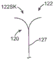
Fig. 1 and 1A are schematic illustrations of a mammalian heart selected to have a native valve configuration suitable for replacement with various prosthetic heart valve devices, in accordance with embodiments of the present technique.
Fig. 1B is a schematic illustration of the left ventricle of a heart having prolapsed leaflets in the mitral valve and which is suitable for combination with various prosthetic heart valve devices, in accordance with embodiments of the present technique.
Fig. 1C is a schematic illustration of a heart that is a heart of a cardiomyopathy patient and that is suitable for combination with various prosthetic heart valve devices, in accordance with embodiments of the present technique.
Fig. 1C-1 is a schematic view of a natural mitral valve of a normally closed heart showing the leaflets of the natural mitral valve.
Fig. 1C-2 are schematic illustrations of a heart showing abnormal closure of the native mitral valve leaflets in an expanded heart, and which is suitable for combination with various prosthetic heart valve devices, in accordance with embodiments of the present technique.
Fig. 1D illustrates mitral regurgitation in the left ventricle of a heart having damaged papillary muscles, and which is suitable for combination with various prosthetic heart valve devices, in accordance with embodiments of the present technique.
Fig. 1E shows a schematic illustration of a mitral valve of a heart showing the size of the annulus and which is suitable for combination with various prosthetic heart valve devices, in accordance with embodiments of the present technique.
Fig. 1F is a schematic cross-sectional view of a heart showing an antegrade approach to a native mitral valve from a venous vessel, in accordance with various embodiments of the present technique.
Fig. 1G is a schematic cross-sectional view of a heart showing access to the interatrial septum (LAS) maintained by placement of a catheter over a guidewire, in accordance with various embodiments of the present technique.
Fig. 1H and 1I are schematic cross-sectional views of a heart showing a method of regurgitation through the native mitral valve of the aortic and arterial vasculature, in accordance with various embodiments of the present technique.
Fig. 1J is a schematic cross-sectional view of a heart showing a native mitral valve approach using transapical puncture, in accordance with various embodiments of the present technique.
Fig. 2a1 and 2a2 are side and top views of a prosthetic heart valve device having a valve portion, a support in a delivery configuration, and a plurality of arms having an outward configuration configured to reach behind leaflets of a native mitral valve, in accordance with one embodiment of the present technique.
Fig. 2A3 is a top view of the device of fig. 2a1 and 2a2 with supports in an expanded configuration and showing the valve open, in accordance with embodiments of the present technique.
Fig. 2a4 is a top view of the devices of fig. 2a1 and 2a2 with supports in an expanded configuration and showing the valve closed, in accordance with embodiments of the present technique.
Fig. 2a5 is a side view of individual arm m in accordance with embodiments of the present technique.
Fig. 2a6 is a schematic diagram illustrating a plurality of arms extending around a native leaflet and between chordae tendineae of a native mitral valve, in accordance with embodiments of the present technique.
Fig. 2A7A-2A7D are end side views of individual arms in accordance with various embodiments of the present technique.
Fig. 2A7E is a side view of a portion of a prosthetic heart valve device showing arms with curved ends inward toward a support for holding a native mitral valve around a proximal end of the support, in accordance with embodiments of the present technique.
Fig. 2A8 is a top view of a prosthetic heart valve device showing a support and a plurality of arms, wherein the arms are in an inward configuration, and wherein pressure reducing ends of the arms are directed along a surface of the support, in accordance with embodiments of the present technique.
Fig. 2a9 is a side view of a prosthetic heart valve device showing arms in an outward configuration at a different opening angle than supports configured in accordance with embodiments of the present technique.
Fig. 2a10 and 2a11 are top and side views, respectively, of a support and a plurality of arms arranged in different opening angles relative to a longitudinal axis of the support configured in accordance with embodiments of the present technique.
Fig. 2B-1 is a schematic cross-sectional view of a heart showing delivery of a prosthetic heart valve device positioned in the distal end of a delivery catheter to the native mitral valve MV region, in accordance with various embodiments of the present technique.
Fig. 2B-2 is an enlarged cross-sectional view of the prosthetic heart valve device within an introducer sheath for delivery to the native valve region of the heart.
Fig. 2C is an isometric side view of the prosthetic heart valve device of fig. 2B-2 with the catheter sheath retracted from the plurality of arms and showing the plurality of arms extending outwardly from the support for positioning in a native valve configuration and configured in accordance with embodiments of the present technique.
Fig. 2C1 is a top view of the device shown in fig. 2C.
Fig. 2C2 is a side view of a separate arm configured with a variable length and in accordance with another embodiment of the present technique.
Fig. 2C3 and 2C4 are side views of separate arms showing a first outward configuration before expansion of the struts and a second outward configuration after expansion of the struts in accordance with embodiments of the present technique, respectively.
Fig. 2C5 and 2C6 are side views of an individual arm of embodiments of the present technology, illustrating the twisting motion of the arm when transitioning from a first outward configuration (fig. 2C5) to a second outward configuration (fig. 2C 6).
Fig. 2D is a schematic diagram of aspects of the present technique, showing various views above a prosthetic heart valve device having a plurality of arms positioned behind a central portion of a native valve.
Fig. 2E and 2F are side and top views, respectively, of a prosthetic heart valve device positioned in a native valve and illustrating a support in an expanded configuration and a plurality of arms extending outward from the support to behind the native leaflets, in accordance with aspects of the present technique.
Fig. 2F1-a and 2F1-B are side and top views, respectively, of a prosthetic heart valve device having a seal configured to be positioned adjacent a native valve commissure, in accordance with another embodiment of the present technique.
Fig. 2F2-a and 2F2-B are isometric side and top views, respectively, of a prosthetic heart valve device having a bell-shaped edge configured in accordance with another embodiment of the present technique that tapers from an open downstream end to a closed, narrower upstream end.
Fig. 2F3A-2F3B and 2F4A-2F4C are side views of a prosthetic heart valve device having alternative edges in accordance with further embodiments of the present technique.
Fig. 2F5A and 2F5B are top and cross-sectional side views, respectively, of a prosthetic heart valve device showing leaflet pushers in an open or separated configuration, in accordance with embodiments of the present technique.
Fig. 2F5C and 2F5D are top and cross-sectional side views, respectively, of a prosthetic heart valve device having a leaflet pusher in a closed or outward configuration configured in accordance with embodiments of the present technique.
Figure 2G is a schematic diagram and side view of a prosthetic heart valve device having a support shown in an expanded configuration and a plurality of arms extending between chordae tendineae, in accordance with various embodiments of the present technique.
Fig. 2H-1 is an isometric view of a prosthetic heart valve device having a flange extending outwardly from a support at a proximal upstream end configured in accordance with another embodiment of the present technique.
Fig. 2H-2 is an isometric view of a prosthetic heart valve device having a support configured in accordance with yet another embodiment of the present technique, the support having a plurality of elongate fingers extending radially outward from a proximal upstream end of the support.
Fig. 2I is an isometric view of a prosthetic heart valve device configured to be positioned in a natural aortic valve, in accordance with another embodiment of the present technique.
Fig. 2J is a top view of a prosthetic heart valve device having a plurality of seals configured to extend toward a tricuspid valve commissure of a native aortic valve, in accordance with yet another embodiment of the present technique.
Fig. 3A is an isometric view of a prosthetic heart valve device having an expandable support shown in a delivery configuration and having a plurality of arms shown in an inward configuration such that the apparatus is suitable for percutaneous access to a subject's valve, in accordance with various embodiments of the present technique.
Fig. 3B, 3C, and 3D show front, side, and top views, respectively, of a device having an expandable support and a plurality of arms configured as in fig. 3A.
Fig. 3E is an isometric view of a prosthetic heart valve device having an expandable support shown in a delivery configuration and a plurality of arms shown in an outward configuration, configured in accordance with yet another embodiment of the present technique, such that the arms are positioned to receive leaflets of a native valve between the arms and the expandable support.
Fig. 3F, 3G, and 3H show front, side, and top views, respectively, of a device having an expandable support and a plurality of arms configured as in fig. 3E.
Fig. 3I is an isometric view of a prosthetic heart valve device having an expandable support shown in an expanded configuration and a plurality of arms shown in an outward configuration, configured in accordance with other embodiments of the present technique, such that the device is adapted to be coupled to an annulus of a native valve.
Fig. 3I1 is a force diagram illustrating forces exerted on an arm during contraction and showing corresponding forces to a brace and strut of a support, in accordance with aspects of the present technique.
Fig. 3J, 3K, and 3L show front, side, and top views, respectively, of a device having an expandable support and a plurality of arms configured as in fig. 3I.
Fig. 4A and 4B are side views of prosthetic heart valve devices having multiple arms and multiple lengths (fig. 4B) shown in a first inward configuration (fig. 4A) and an outward configuration, configured in accordance with other embodiments of the present technique.
Fig. 5 Al-5 a4 are side views of a prosthetic heart valve device having arms with looped ends configured in accordance with embodiments of the present technique.
Fig. 5a5 is a partial side view of a prosthetic heart valve device having arms with a first, flattened cross-sectional dimension and a second, elongated cross-sectional dimension such that the arms have relative impedances that bend in different directions and are configured in accordance with embodiments of the present technique.
Fig. 5A6A shows a portion of the arm along line AA of fig. 5a 5.
Fig. 5A6B shows a portion of the arm along line BB of fig. 5a 5.
Fig. 5a7-5A8 are side and front views, respectively, of a prosthetic heart valve device having arms configured in accordance with embodiments of the present technique that include arm tips with curved end portions for providing planar sub-ring interface tips.
Fig. 5a9-5Al0 are partial side views of a prosthetic heart valve device having an arm with a loop and two support connection points configured in accordance with embodiments of the present technique. The annular arms can be adapted for retention within the delivery catheter in an outward configuration (fig. 5a9) to be positioned in a native valve configuration or in an inward configuration (fig. 5Al0) with a low cross-sectional profile.
Fig. 5All is a perspective view of another embodiment of a prosthetic heart valve device having a cover thereon in accordance with aspects of the present technique.
Fig. 5a12-5a15 are partial side views illustrating various embodiments of covers on arms of a prosthetic heart valve device in accordance with aspects of the present technique.
Fig. 6a 1-6B4 are bottom, front, side views of a prosthetic heart valve device showing arms spanning from a support attachment site on a first side of a support to coaptation to a leaflet and/or annulus oriented to a site on a second side of the support opposite the first side, configured in accordance with another embodiment of the present technique.
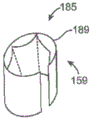
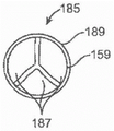
Fig. 7A is a top view of a prosthetic heart valve device having an expandable support with arms and a separate prosthetic valve retained and positioned inside of the expandable support configured in accordance with embodiments of the present technique.
Fig. 7a1 is a perspective view of an individual prosthetic valve in an expanded configuration and configured for use with an expanded support of a prosthetic heart valve device configured in accordance with embodiments of the present technique.
Fig. 7B is a top view of a prosthetic heart valve device having an expanded support with arms and a temporary valve configuration and showing a prosthetic valve separately retained and positioned within the expanded support and within the temporary valve configuration and configured in accordance with another embodiment of the present technique.
Fig. 7B1-7B3 show various components and configurations of a temporary valve including leaflets, in accordance with embodiments of the present technique.
Fig. 7C is a top view of a prosthetic heart valve device having an expandable support with multiple arms and a temporary valve mounted within the expandable support configured in accordance with embodiments of the present technique.
Fig. 8A-8C are enlarged cross-sectional views of a delivery catheter valve including an inner shaft, a tubular intermediate shaft slidable over the inner shaft, and a sheath configured over the intermediate shaft and configured in accordance with embodiments of the present technique.
Fig. 9A-9D are enlarged cross-sectional views of delivery catheters having inner and intermediate shafts in accordance with further embodiments of the present technique.
FIG. 10 is an enlarged cross-sectional view of a delivery catheter including a second sheath slidably disposed within the first sheath, wherein the second sheath is configured to slide between an outer surface of a support and a plurality of arms of a prosthetic heart valve and is configured in accordance with yet another embodiment of the present technique.
11A-11C are side cross-sectional views of a distal portion of a delivery system of a prosthetic heart valve device configured in accordance with another embodiment of the present technique.
12A-12C are side views of components of a delivery system for a prosthetic dirty valve device configured in accordance with additional embodiments of the present technique.
12D-12G are side views of the distal portion of the delivery system of FIGS. 12A-12C with a prosthetic heart valve device disposed therein and showing various arrangements of the devices during deployment of the devices from the delivery system, in accordance with embodiments of the present technique.
Fig. 13A-13B are elevated and angled views, respectively, of a prosthetic heart valve device having a band coupled between an expandable support and a plurality of arm assemblies configured in accordance with embodiments of the present technique.
Fig. 13C-13D are top views of the device of fig. 13A-13B, showing the arms in an outward direction (fig. 13C), and in an inward direction or configuration (fig. 13D) in accordance with aspects of the present technique.
FIG. 14 is an elevated side view of a prosthetic heart valve device having a pair of straps coupled between an expandable support and a plurality of arms configured in accordance with another embodiment of the present technique.
15A-15C are side views of a portion of a separate arm associated with a prosthetic heart valve device and illustrating a mechanism for coupling a band with the arm, in accordance with various embodiments of the present technique.
Figures 16A-16C are oblique views illustrating the fabrication of an arm of a prosthetic heart valve device, wherein the arm has a small hole for receiving a band.
Detailed Description
Specific details of some embodiments of the present technology will be discussed below with reference to fig. 1-16C. Although many embodiments of devices, systems, and methods relating to percutaneous replacement using prosthetic valve devices are discussed below, other applications and other embodiments in addition to those described herein are within the scope of the present technology. Moreover, some other embodiments of the present technology may have different configurations, components, or operations than those described herein. Accordingly, those of ordinary skill in the art will accordingly appreciate that the present technology is capable of other embodiments with additional elements or that the present technology is capable of other embodiments without several of the features shown and described below with reference to FIGS. 1-16C.
With respect to the terms "distal" and "proximal" in this specification, unless otherwise specified, the terms may refer to the relative positions of portions of the prosthetic valve device and/or associated delivery device with reference to the operator and/or the location in the vessel or heart. For example, in referring to the various prosthetic valve devices described herein that are suitable for delivery and positioning with a delivery catheter, "proximal" may refer to a location closer to an operator of the device or an incision into the vasculature, while "distal" may refer to a location further from an operator of the device or an incision along the vasculature (e.g., the end of a catheter). The terms "proximal" and "distal" with respect to a prosthetic heart valve device may refer to the position of portions of the device relative to the direction of blood flow. For example, proximal may refer to an upstream location or a location of blood inflow, and distal may refer to a downstream location or a location of blood outflow. For ease of reference, the same reference numbers and/or letters are used throughout this disclosure to identify similar or analogous elements or features, but the use of the same reference number does not imply that the parts are to be considered identical. Indeed, in many of the embodiments described herein, like numbered parts differ in configuration and/or function. Headings are provided herein for convenience only.
SUMMARY
Systems, devices, and methods are provided herein for percutaneous replacement of a native heart valve, such as a mitral valve. Several details are set forth below to describe the following embodiments and methods in a manner sufficient to enable those skilled in the relevant art to practice, make, and use them. However, several of the details and advantages described below may not be necessary to practice certain examples and methods of the technology. Moreover, the techniques may include other embodiments and methods that are within the scope of the claims but not described in detail.
Embodiments of the present technology provide systems, methods, and devices for treating valves of the body, such as heart valves including the mitral valve. The devices and methods can use a percutaneous approach of inserting a delivery catheter into a cardiac vessel through a vein or artery. In addition, the devices and methods use other less invasive methods, including trans-apical, trans-atrial, and direct aortic delivery of prosthetic replacement valves to target sites in the heart. The devices and methods enable the prosthetic device to be secured in place of the native valve to engage the subannular surface of the annulus and/or leaflets. According to various embodiments of the present technique, the annulus or leaflets are coaptated within a subannular space behind (radially outward of) the native leaflets. In particular embodiments, the sub-ring surfaces are engaged by one or more elongated members or arms that extend from a location downstream of the native leaflets. The elongate member may surround at least a downstream edge of the native leaflet and may further pass between two or more chordae tendineae coupled to the native leaflet. The elongated member may have an upstream end configured to engage the surface of the sub-ring. In some embodiments, the elongated member is oriented generally perpendicular to the sub-ring surface, or at an oblique angle between about 45 and 135 degrees relative to the sub-ring surface, such that the load exerted by the load on the elongated member is primarily a compressive, axial load. The prosthetic device can include a support coupled to the elongate member that contains the prosthetic valve, or that is configured to receive a separately delivered prosthetic valve, such as a stented valve prosthesis. The elongate member may be configured to maintain the position of the prosthetic device and resist movement in at least an upstream direction when the device is subjected to blood pressure downstream of the valve and when the valve is closed.
In some embodiments, the arms of the present device may be shorter in length so as not to extend completely to the annulus tissue behind the coaptation leaflets. Furthermore, in some configurations, the arms may include a short hook that extends around the free edge of the natural leaflet and only a short distance behind the leaflet sufficient for the arms to slide out of the leaflet. The arms may alternatively be configured to engage or couple to chordae tendineae, papillary muscles or ventricular walls to enhance anchoring. Further, the arms can be configured to remain on the inside of the native leaflets as well as to engage the leaflets themselves, or penetrate the leaflets to contact the annulus or other tissue behind the leaflets. All of the various features and characteristics of the arms described herein may be applicable to longer arms that engage subannular tissue, as well as shorter arms or arms that remain on the inside of the leaflets. In addition, the device may contain or incorporate multiple arms of different lengths or with different patterns of arms that engage the leaflets or other native tissue.
The devices, systems, and methods described herein overcome many of the challenges of existing percutaneous valve replacement methods. In particular, the devices and methods may eliminate the need to rely solely on outward force of radial engagement against the native valve annulus in order to secure a prosthetic device (such as a replacement valve) to the native valve. The devices and methods may be well suited for treating non-circular, asymmetrical valves and bileaflet or bileaflet valves, such as the mitral valve. The devices and methods also provide permanent and reliable anchoring of the prosthetic device even under conditions where the heart or native valve may encounter gradual enlargement or distortion.
Some embodiments of the present disclosure relate to prosthetic heart valve devices for implantation at a native valve located between an atrium and a ventricle of a heart of a patient. Such devices are suitable, for example, for implantation at a native valve having an annulus and leaflets coupled to the annulus. In one embodiment, a device can have an expandable support having an outer surface and configured to be placed between leaflets. The device may also have a plurality of arms coupled to or otherwise extending from the expandable support, and the plurality of arms configured to receive the leaflets between the arms and the outer surface of the expandable support. In some embodiments, the at least two arms may have different lengths to extend different distances behind the leaflets to engage the sub-annular surface of the annulus. In other embodiments, the plurality of arms can be asymmetrically disposed about a circumference of the expandable support and configured to receive the leaflets between the arms and the outer surface. In some examples, asymmetrically configured arms may have arms with varying distances between adjacent arms. Alternatively or additionally, the arms may be asymmetrically arranged about a longitudinal axis passing through the centre of the expandable support, e.g. more axes are provided on one side of the arms than on the other side. In other examples, the asymmetrically configured arms may be arms having different lengths or different extension angles, wherein an extension angle is the angle between the upstream extension of an arm and the vertical or longitudinal axis of the support. In a further embodiment, the asymmetrically configured arms may be arms having different opening angles for increasing or decreasing the distance between the ends of adjacent arms. One skilled in the art will recognize other ways to asymmetrically arrange the arms around the circumference of the expandable support.
In another embodiment, the device may further comprise a seal coupled to the at least one expandable support and the arm. The seal, in some embodiments, can be a membrane configured to extend from the expandable support to the commissure regions of the valve to inhibit blood flow through the commissure regions of the valve. In some embodiments, the device may include two seals (which may be in a membranous or rigid configuration) oriented on the device to inhibit blood flow through the commissure regions of the mitral valve (e.g., mitral valve or aortic valve leaflets). In another embodiment, the device may include three or more seals oriented on the device to inhibit blood flow through the commissure regions of the tricuspid (e.g., aortic) or other valve. In another embodiment, the device may include a single skirt membrane oriented over the device to inhibit blood flow through the gap formed between the device and the native valve.
Other embodiments of the present invention are directed to prosthetic heart valve devices for implantation at a native valve region of the heart. In one embodiment, a device may include an expandable support having an upstream portion and a downstream portion. The expandable support may also be configured to be positioned in the natural valve region such that the upstream portion is in fluid communication with a first heart chamber and the downstream portion is in fluid communication with a second heart chamber or portion. In one embodiment, the natural valve region may be a mitral valve region and the first heart chamber may be the left atrium and the second heart chamber may be the left ventricle. In another embodiment, the natural valve region may be an aortic valve region and the first heart chamber may be the left ventricle and the second heart chamber or portion may be the aorta.
The prosthetic heart valve device may further include a plurality of arms coupled at a downstream portion to the expandable support. The arms, for example, may be integrally formed with the expandable support, or the arms may be separate members that are attached (e.g., spot welded) to the expandable support. In one embodiment, each individual arm may be configured to extend from the downstream portion to engage a sub-ring surface of a natural valve region within the second chamber (or portion). In some embodiments, at least some of the individual arms have independently adjustable lengths. In other embodiments, each individual arm may have a base portion, an extension portion, and an elbow portion connecting the base to the extension portion. In some embodiments, the extension portion may be configured to engage a sub-annulus surface of a natural valve region within the second chamber or portion. In a further embodiment, separate arms extend from the support at different opening angles.
Further embodiments of the present technology provide an apparatus to treat a heart valve of a patient, wherein the valve includes an annulus and leaflets coupled to the annulus. The device may include an expandable support including an outer surface, an upstream portion, and a downstream portion. The support may be configured to be placed between the leaflets. The device may also include a plurality of arms coupled to the expandable support. In some arrangements, the plurality of arms may include a first plurality of arms and a second plurality of arms. A first plurality of arms can be disposed over a first portion of the support to receive a first leaflet and a second plurality of arms can be disposed over a second portion of the support to receive a second leaflet. In some embodiments, the first plurality of arms may include a greater number of arms than the second plurality of arms.
Another embodiment of the present technology provides a device for repairing or replacing a bilobal heart valve having an annulus, leaflets coupled to the annulus, and chordae tendineae coupled to the leaflets. The device can include a hollow support positionable between the leaflets and having an interior to which the valve can be coupled. The device may further include an anchoring portion coupled to the support. The anchor portion may have an arcuate region configured to extend around a downstream edge of the at least one leaflet, an extension region configured to extend from the downstream edge between the chordae tendineae to the annulus, and an engagement region configured to engage the downstream edge of the annulus so as to inhibit movement of the device in an upstream direction. The device may also optionally include a seal coupled to the at least one support and the anchor portion and extending outwardly from the expandable support to the commissure region of the mitral valve for occluding the commissure region to inhibit blood flow through the commissure region. In some embodiments, the membrane may be a seal configured to engage a ventricular or downstream commissure region of the bilobal heart valve.
Further embodiments of the invention relate to devices for repairing or replacing a heart valve having an annulus and leaflets coupled to the annulus. In one embodiment, the device can include a cylindrical support configured to be placed between the leaflets. The support may include proximal and distal portions, or in other embodiments upstream and downstream portions. The cylindrical support may further comprise an inner portion in which the valve is coupled. The device may further include a first set of arms (e.g., anchor arms) coupled to the back side of the cylindrical support to couple to a second set of arms (e.g., anchor arms) of the front side of the cylindrical support opposite the back side. In one embodiment, each arm may be configured to extend around a downstream edge of the leaflet and between chordae tendineae. Each arm may also engage a sub-ring surface of the annulus to inhibit movement of the support in an upstream direction. In some arrangements, the first set of arms may be configured to engage a first sub-ring surface along a first line and the second set of arms may be configured to engage a second sub-ring surface along a second line. In some embodiments, the first and second lines may not be parallel to the annulus. For example, in one embodiment, the first and second lines are substantially straight, while in another embodiment, the first and second lines may have a curvature that is substantially greater than the radius of the annulus.
In some embodiments, the anchor arms may be coupled to a downstream portion of the cylindrical support and extend outward in an upstream direction. The anchoring arm may have a distal end and be configured to atraumatically engage an annulus of the heart valve. In some arrangements, the plurality of anchoring arms may include first and second pluralities of anchoring arms. The first plurality of anchor arms may have different characteristics than the second plurality of anchor arms. Examples of such arm characteristics may include size, shape, stiffness, opening angle, spacing from the support, and the number of arms disposed within a given area of the support. One of ordinary skill in the art will recognize other arm features that may vary between separate sets of arms coupled to the support and/or the supports associated with the devices disclosed herein.
In another embodiment, the cylindrical support may have an upstream end and a downstream end, an interior into which the valve may be coupled, and a periphery. A plurality of arms may be coupled to the cylindrical support and extend outward and in an upstream direction. The arms may include distal ends configured to atraumatically engage an annulus of a heart valve. Further, the arms may be non-uniform or otherwise irregularly distributed about the circumference such that at least a first adjacent pair of arms are spaced apart a lesser distance than at least a second adjacent pair of arms.
Other embodiments of the present invention are directed to prosthetic heart valve devices having a cylindrical support with an upstream end and a downstream end, an interior into which a valve may be coupled, and a longitudinal central axis. The device may further comprise a plurality of arms extending outwardly from the cylindrical support in an upstream direction. The arms may have distal ends configured to atraumatically engage a subannular surface of a native heart valve. In some embodiments, at least one arm may extend outwardly from the longitudinal axis a greater distance than at least a second arm extends outwardly from the longitudinal axis.
In certain embodiments, a prosthetic heart valve device may also include an expandable support having an upstream portion and a downstream portion. The support, for example, may be configured to be positioned at a natural valve region such that the upstream portion is in fluid communication with a first heart chamber and the downstream portion is in fluid communication with a second heart chamber. The apparatus may also include at least one arm coupled to the support and extending in an upstream direction, the distal end configured to engage an annulus of a native surface region in the second heart chamber. The arm may have a column strength selected to maintain the position of the support relative to the surface of the heart under the influence of blood during contraction (e.g., at least about 0.5 pounds of force applied to the support in the upstream direction). If multiple arms are utilized, the column strength of each arm can be selected so that the arms in combination maintain the position of the support relative to the heart valve under such a systolic load.
Some devices may include a cylindrical support having a longitudinal axis through which blood may flow and an interior along the longitudinal axis. The device may further include a valve coupled inside of the support, the support configured to impede blood flow through the support in an upstream direction and allow blood flow through the support in a downstream direction. The apparatus may also include a plurality of arms coupled to the support and extending along an outer wall or surface of the support in the upstream direction. The device may be movable into a plurality of configurations, which may include a) a first configuration in which the support is radially contracted and each arm is in an inward position against or adjacent to an outer wall of the support, b) a second configuration in which the support is radially contracted and each arm is in an outward position spaced apart from the outer wall by a distance sufficient to receive a leaflet between the heart valve, and c) a third configuration in which the support is radially expanded and each arm is located closer to the outer wall of the support than the second configuration.
In many embodiments, the device includes an expandable support coupled to the plurality of arms. The expandable support may include an upstream portion for placement adjacent to the upstream portion of the valve and a downstream portion for placement adjacent to the downstream portion of the valve. A plurality of arms can extend from the downstream portion and can include an inward configuration for placement in a lumen of the catheter and an outward configuration to behind the leaflets and engage the annulus. An expandable support and a plurality of arms can be percutaneously introduced into a patient, the plurality of arms including an inward configuration and the expandable support including a first, non-expanded configuration such that the support and the plurality of arms can be advanced along a lumen of a catheter toward a predetermined valve. A sheath covering the plurality of arms and the expandable support may be pulled proximally to expose the plurality of arms, and the plurality of arms may be moved outwardly from the expandable support to include an outward configuration. In the outward configuration, the plurality of arms may extend between chordae tendineae of the mitral valve and receive leaflets between the plurality of arms and the support in some embodiments. The support may be movable upstream with the leaflets received between the plurality of arms and the support to direct the plurality of arms toward the annulus. When the support has moved upstream a sufficient distance, the plurality of arms can engage the annulus and the leaflets extend substantially between the plurality of arms and the support such that the plurality of arms can engage the annulus in direct contact and reduce interference with other leaflets. The expandable support is expandable to an expandable configuration when the plurality of arms engage the annulus in the outward configuration. The arms may be flexible enough to deflect inwardly or outwardly relative to the support to accommodate any enlargement or deformation of the native annulus that may occur in a heart suffering from mitral valvulopathy, congestive heart failure, or other conditions.
A valve may be provided that is configured to be coupled to the support when the support is in the deployed configuration. The valve may be delivered from and coupled to the support, respectively, after the support is implanted at the native valve. Alternatively, the valve may be pre-mounted to the support and delivered to the target site. The valve may also be a temporary valve that regulates blood flow through the support for a period of time (e.g., 15 minutes to 3 days) until a permanent prosthetic valve is delivered and coupled to the support. The valve may be supported by a plurality of arms that engage a ventricular side of the annulus behind the valve leaflets and the arms in an outward configuration such that the valve is supported by direct coupling to the native annulus. Engagement of the annulus by the plurality of arms may provide a secure and reliable coupling to the native valve. The integrity of the adjacent tissue and configuration may be substantially maintained and blood flow through the aortic outflow tract may be substantially unimpeded. The arms may include sufficient strength to support the valve and maintain its position during contraction, and the strength may include a column strength that keeps the arms from bending or rupturing under blood pressure acting on a valve coupled to the support.
The plurality of arms can include one or more valve annuli configured to couple to the valve. Each of the plurality of arms may include an end to inhibit infiltration of the annulus. The end portion may include a cross-sectional dimension to inhibit excessive infiltration of the annulus. The plurality of arms may include a portion to provide deflection of the end.
Each of the plurality of arms may include a mechanism to change the length of the arm, such as a retractable member. The mechanism may include a locking mechanism that locks when the plurality of arms engage the annulus. Alternatively or in combination, the plurality of arms may be shaped to engage the annulus of the mitral valve. The first plurality of arms may be configured to engage a first portion of the annulus on a first side of the support and the second plurality of arms may be configured to engage a second portion of the annulus on a second side of the support. Each of the first and second plurality of arms can flare outward from a surface of the support and be configured to pass between chordae tendineae coupled to the leaflets with minimal interference.
In many embodiments, the support may be configured to receive an expandable valve when the support is in an expanded configuration. The expandable valve may comprise an expandable stent-valve, and the support may comprise a retaining configuration to couple to the expandable stent-valve with one or more friction, compression, or interlocking elements. In some embodiments, the expandable support is configured to receive an expandable aortic stent valve when the support is placed at the mitral valve. The support may be disposed in an expandable configuration when coupled to the expandable aortic stent-valve and configured such that the support and the plurality of arms substantially maintain the shape and size of the native annulus and do not overly extend into the aortic outflow tract such that blood flow through the aortic outflow tract is substantially unobstructed.
Certain embodiments of the present technology provide a device for treating a mitral valve located between an atrium and a ventricle of a heart of a patient. The mitral valve has an annulus, leaflets coupled to the annulus, and chordae tendineae coupled to the leaflets. The device includes an expandable stent including an outer surface. The expandable support is configured to be placed between the leaflets and includes an upstream portion and a downstream portion. A plurality of arms are coupled to the expandable support. The plurality of arms are configured to receive the leaflets between the arms and the outer surface and extend behind the leaflets so as to engage the annulus.
In many embodiments, the plurality of arms are configured to engage the annulus so as to inhibit movement of the support toward the atrium. Collectively, the plurality of arms may have a column strength sufficient to support a systolic load of at least about 2-5 pounds of force applied in an axial direction of the support. In some embodiments, each arm can be configured to support an axial compressive load of at least about 0.2 pounds-force, and in other embodiments, at least about 0.5 pounds.
In many embodiments, the valve is coupled to the support and configured to inhibit retrograde blood flow when the left ventricle of the heart contracts, and the plurality of arms extend from the support to the annulus so as to couple the valve to the annulus.
In many embodiments, the plurality of arms are configured to contact the leaflets, thereby further resisting movement of the support. Each of the plurality of arms can be spaced from the outer surface by a gap distance sized to receive a leaflet such that the leaflet is received between the plurality of arms and the support. The gap distance associated with each of the plurality of arms can be sized to direct the plurality of arms toward the annulus. Each of the plurality of arms can be independently deflected to change the gap distance if engaging tissue during positioning. The arm may also be configured to move the playing card from a first position having a first gap distance to a second position having a second gap distance, the first gap distance being greater than the second gap distance. The arms may be automatically moved from the first position to the second position when the support is expanded to the expanded configuration, or the arms may be actively moved before or after the support is expanded as desired. The arm may be further moved to a third position having a smaller gap distance than the first position or the second position, wherein the arm has a minimum profile to facilitate intravascular delivery to the target site. The arm may have an unbiased configuration corresponding to the first, second or third position.
In another aspect, embodiments of the present technology provide a method of treating a mitral valve in a patient, wherein the mitral valve annulus and leaflets. The method includes placing a device comprising an expandable support coupled to a plurality of arms along the mitral valve such that the plurality of arms engage the annulus behind the valve leaflets.
In a further aspect, embodiments of the present technology provide a system to treat a mitral valve of a patient, wherein the mitral valve has an annulus. The system includes a device for treating a mitral valve as described herein and a catheter having a device in a lumen of the catheter.
In another aspect, embodiments of the present technology provide a method of treating a valve of a heart of a patient. The valve has an annulus and leaflets. Methods may include implanting a device as described herein within or adjacent to the annulus. In some embodiments, the device may include an expandable support coupled to the plurality of arms. The support may be disposed between the leaflets and a plurality of arms, which may be configured to engage the annulus behind the leaflets. Accordingly, the method may further include engaging the annulus behind the valve leaflets with a plurality of arms coupled to the expandable support to inhibit movement of the support, and, in some embodiments, coupling the valve to the support to allow blood to flow through the support in a first direction and inhibit blood from flowing through the support in a second direction.
In another aspect, embodiments of the present technology provide a device for treating a valve of a patient, wherein the valve includes an annulus and leaflets coupled to the annulus. The expandable support includes an outer surface, and the expandable support is configured to be placed between the leaflets. The expandable support includes an upstream portion and a downstream portion when placed between the leaflets. A plurality of arms are coupled to the expandable support and extend from the downstream portion. The plurality of arms includes a first plurality of arms and a second plurality of arms. A first plurality of arms is disposed on a first portion of the support for receiving a first leaflet and a second plurality of arms is disposed on a second portion of the support for receiving a second leaflet. At least some of the first and second plurality of arms engage the annulus behind the first and second leaflets to inhibit movement of the support. A temporary or permanent valve may be coupled to the support to allow blood flow in a first direction and inhibit blood flow in a second direction.
In another aspect of the technology, a method of securing a treatment device in position proximate a native valve of a heart of a patient. The method can include passing a first arm of a treatment device around a free edge of a first leaflet to a first sub-annular space behind the first leaflet; passing a second arm of the treatment device around a free edge of a second leaflet to a second sub-annular space behind the second leaflet; and a space of the annulus and the first and second arms engaged behind the leaflets to inhibit movement of the treatment device relative to the native valve in an upstream direction.
In another aspect, a valve device for treating a patient includes an expandable support including an outer surface, the expandable support configured to be positioned between valve leaflets and including an upstream portion and a downstream portion; and a plurality of arms coupled to the expandable support, the plurality of arms including a first plurality of arms disposed on a first portion of the support for receiving a first leaflet and a second plurality of arms disposed on a second portion of the support for receiving a second leaflet.
In another embodiment, a device for repairing or replacing a heart valve having an annulus, leaflets coupled to the annulus, and chordae tendineae coupled to the leaflets includes a support portion positioned between the leaflets, and the support portion has an interior to which the valve can be coupled; an anchoring portion is coupled to the support portion, the anchoring portion having a rotation region configured to extend around a downstream edge of the at least one leaflet, an extension region configured to extend from the downstream edge between the chordae tendineae to the annulus, and an engagement region configured to engage the annulus so as to inhibit movement of the device in an upstream direction.
In another aspect, the present technology provides a device for repairing or replacing a heart valve having an annulus, leaflets coupled to the annulus, and chordae tendineae coupled to the leaflets, the device comprising a cylindrical support configured to be placed between the leaflets, the support having an upstream end and a downstream end and an interior into which the valve can be coupled; a first set of arms is coupled to the support along a posterior side thereof, and a second set of arms is coupled to the support along an anterior side thereof opposite the posterior side, wherein each arm is configured to extend around a downstream edge of a leaflet, extend between chordae tendineae, and engage the annulus so as to inhibit movement of the support in an upstream direction.
In another embodiment, an apparatus for repairing or replacing a heart valve having an annulus may include a cylindrical support configured for placement between leaflets, the support having an upstream end and a downstream end and an interior portion that may be coupled therein; and a plurality of arms coupled to the cylindrical support and extending in an upstream direction, the distal end configured to engage annulus tissue of the heart valve, wherein the first plurality of arms has a different characteristic than the at least second plurality of arms, the characteristic selected from a size, a shape, a stiffness, an angle, a spacing from the support, or a number of arms in a given region of the support.
In another aspect of the present technique, a heart valve device for repairing or replacing a heart valve having an annulus may be provided. The device may comprise a cylindrical support having an upstream end and a downstream end, an interior into which the valve may be coupled, and a circumference; and a plurality of arms coupled to the cylindrical support and extending in an upstream direction with a distal end of the annulus tissue configured to atraumatically engage the heart valve; wherein the arms are unevenly distributed about the circumference such that at least a first adjacent pair of arms is spaced closer together than at least a second adjacent pair of arms.
In another embodiment, an apparatus for repairing or replacing a heart valve having an annulus may include an inner portion having an upstream end and a downstream end, the valve possibly coupled therein, and a longitudinal central axis; and a plurality of arms coupled to the cylindrical support and extending in an upstream direction with a distal end of the annulus tissue configured to engage the heart valve; wherein at least one of the arms extends outwardly from the longitudinal axis a greater distance than at least one of the second arms extends outwardly from the longitudinal axis.
In yet another aspect, the present technology provides a heart valve device for repairing or replacing a heart valve having an annulus, the heart valve including an annulus having an upstream end and a downstream end and an interior into which the valve may be coupled; and at least one arm coupled to the circumferential support and extending in an upstream direction with a distal end of the heart valve annulus configured to engage a valve leaflet therebehind, the at least one arm having a column strength selected to maintain a position of the support relative to the heart valve under a force of at least about 0.5 pounds applied to the support in the upstream direction.
In yet another aspect of the present technique, a device for heart valve replacement includes a cylindrical support having an interior through which blood can flow; a valve coupled within an interior of the support and configured to block blood flow through the support in an upstream direction and allow blood flow through the support in a downstream direction; and a plurality of arms coupled to the support and extending along an outer wall of the support in an upstream direction; wherein the device is movable into a plurality of configurations, including a first configuration in which the support is radially contracted and each arm is in an inward position against or adjacent to an outer wall of the support; the support is radially contracted in the second configuration and each arm is in an outward position separated from the outer wall by a distance sufficient to receive a leaflet between the heart valve; and the support is radially expanded in the third configuration and each arm is located closer to the outer wall of the support than in the second configuration.
Additional aspects of the present technology are further described herein. It is contemplated that the embodiments described herein may be combined in a variety of ways and that elements of any one or more of the claims may be combined together in accordance with embodiments of the present technology and teachings as described herein.
Embodiments of the present technology as described herein may be combined in a variety of ways to treat one or more of a number of valves of the body, including heart valves (e.g., mitral valves). Embodiments of the present technology may be combined with many known surgical procedures and methods, for example, such embodiments may be combined with known methods of accessing heart valves (e.g., mitral valve antegrade or retrograde methods, and combinations thereof).
Cardiac physiology
Fig. 1 and 1A show a heart H. The heart includes a right atrium RA and a right ventricle RV that receive blood from the body and draw blood from the body to the lungs. The left atrium receives oxygenated blood from the lungs via the pulmonary veins PV and draws such oxygenated blood through the mitral valve MV into the left ventricle LV. The left ventricle LV pumps blood through the aortic valve AV into the aorta from where it flows through the body.
The left ventricle LV of a normal heart H in contraction is illustrated in fig. 1A. In contraction, the left ventricle LV contracts and blood flows in the direction of the arrow through the aortic valve AV. Blood backflow or "regurgitation" is prevented because the mitral valve MV is configured to act as a "flowing blood" because the mitral valve is configured as a "one-way valve" which may prevent regurgitation when the pressure in the left ventricle is higher than the pressure in the left atrium LA. The mitral valve MV includes a pair of leaflets with free edges FE that conform to uniform, or "coaptate" closure, as shown in fig. 1A. The opposite end of the leaflets LF is affixed to the surrounding cardiac structure via AN annulus region of tissue called the annulus AN. The free edge FE of the leaflet is fixed to the lower part of the left ventricle LV by chordae tendineae CT (hereinafter "chordae"), which comprise a plurality of branched chordae tendineae fixed over the lower surface of each leaflet LF. Alternate chords CT, connected to papillary muscles PM, extend upwardly from the left ventricle and the inferior wall of the interventricular space IVS.
Referring now to fig. 1B through 1D, some structural defects in the heart may cause mitral regurgitation. A ruptured chordae RCT, as shown in fig. 1B, can cause leaflet LF2 to prolapse because insufficient tension is transmitted through the chordae to the leaflet. While the other leaflet, LF1, maintains the normal contour, and incorrect fitting of the two leaflets and leakage from the left ventricle LV into the left atrium LA will occur, as indicated by the arrows.
Regurgitation also occurs in patients with cardiomyopathy where the heart expands and increases in size to prevent the leaflets LF from failing to meet properly, as shown in figure 1C. The enlargement of the heart causes the mitral valve to enlarge, making it impossible for the free edge FE to meet during systole. The free edges of the anterior and posterior leaflets are generally satisfied along the line of coaptation C as shown in fig. 1C1, but a significant gap G may remain in a patient with cardiomyopathy as shown in fig. 1C 2.
Fig. 1C1, 1C2, and 1E further illustrate the shape and relative size of leaflets L of the mitral valve. The whole-body valve can be seen to have a generally kidney shape with a major axis MVA1 and a minor axis MVA 2. The major axis MVA1 in healthy humans is typically in the length range from 33.3 mm to 42.5 mm (37.9+/-4.6 mm) and the minor axis MVA2 is in the length range of about 26.9 to 38.1 mm (32.5+/-9.1 mm). However, these values may be greater for patients with reduced cardiac function, for example, MVA1 may be in the range from about 45 mm to 55 mm and MVA2 may be in the range from about 35 mm to about 40 mm. The line joining C is curved or C-shaped to define a relatively large anterior lobe AL and a much smaller posterior lobe PL (fig. 1C 1). The two leaflets emerge from the superior or atrial side in a generally crescent shape with the anterior leaflet AL in the middle of the valve being substantially wider than the posterior leaflet in the middle of the valve. The leaflets joining together at the corners at opposite ends of the leaflet coaptation C line are referred to as the anterolateral commissure AC and the posteromedial commissure PC, respectively.
Mitral regurgitation can also occur in patients with ischemic heart disease with impaired function of the papillary muscles PM, as shown in fig. 1D. As the left ventricle LV contracts during the systolic phase, the papillary muscles PM do not contract sufficiently to achieve a correct closure. One or both of the leaflets LF1 and LF2 prolapsed later as shown. Leakage again occurs from the left ventricle LV to the left atrium LA as indicated by the arrow.
Fig. 1E shows the shape and size of the mitral annulus. The annulus is the region of the annulus around the circumference of the valve, which is composed of fibrous tissue that is thicker and stiffer than the leaflets LF, and that is distinct from the muscular tissue of the ventricle and atrial wall. The valve annulus can include a saddle shape having a first peak portion PP1 and a second peak PP2 located along a peak-to-peak axis IPD, and a first valley VPI and a second valley VP2 located along an inter-valley axis IVD. The first and second peak portions PP1 and PP2 are relatively high in elevation with respect to a plane containing the trough VP1, the lowest point of VP2, typically about 8-19 mm in height in humans, giving the valve an overall saddle-like shape. The distance between the first and second peaks PP1, PP2, referred to as the peak-to-valley span IPD, is shorter than the distance between the first and second valleys VP1, VP2, the valley-to-valley span IVD.
Those skilled in the art will recognize that the size and physiology of patients may vary, and that while some patients may contain different physiology, the teachings as described herein may be adapted for use with many patients having various mitral valve conditions, sizes, and shapes. For example, work in connection with the present disclosure suggests that some patients may have a long dimension across the annulus and a short dimension across the annulus without well-defined peaks and valleys, and the methods and devices described herein may be configured accordingly.
Accessing a mitral valve
Access to the mitral valve or other atrioventricular valve may be achieved percutaneously through the patient's vasculature. Percutaneous refers to a location of the vasculature remote from the heart being accessed through the skin, typically using a surgical cutting procedure or minimally invasive surgery, such as access through a needle, for example, the Seldinger technique. The ability to percutaneously access remote vasculature is well known and described in the patent and medical literature. Depending on the point of vascular access, the mitral valve approach pair may be antegrade and may rely on entering the left atrium by crossing the interatrial septum. Alternatively, the mitral valve approach may be retrograde, in which the left ventricle is accessed through the aortic valve. Once percutaneous access is achieved, the interventional tool and the auxiliary catheter may be advanced into the heart vessel for placement adjacent the target heart valve in various ways, as described herein.
Using the transseptal approach, access is gained through the right atrium RA, through the entire atrial septum LAS, and into the left atrium LA above the mitral valve MV via the inferior vena cava LVC or the superior vena cava SVC.
As shown in fig. 1F, a catheter 10 having a needle 12 may be advanced from the inferior vena cava LVC to the right atrium RA. Once catheter 10 reaches the anterior side of interatrial septum LAS, needle 12 may be advanced so that it penetrates the septum, e.g., into left atrium LA at fossa ovalis FO or foramen ovale. At this point, the guidewire may be used to exchange the needle 12 and the catheter 10 withdrawn.
As shown in fig. 1G, access through the interatrial septum LAS may generally be maintained by placement of a guide catheter 14, generally over a guidewire 16 that has been placed as described above. The guide catheter 14 can provide subsequent access to allow introduction of the device to replace the mitral valve, as will be described in more detail below.
The method of antegrade or trans-ventricular spacing of the mitral valve, as described above, may be advantageous in a number of respects. For example, the use of an antegrade approach will generally allow for more accurate and more effective centering and stabilization of the guide catheter and/or prosthetic valve device. Precise positioning facilitates accuracy in placement of the prosthetic valve device. Antegrade methods may also reduce the risk of damaging the subglottal device during catheter and tool introduction and manipulation. Furthermore, the antegrade approach may reduce the risks associated with crossing the aortic valve in a retrograde approach. This may be of particular relevance to a prosthetic aortic valve of a patient that does not experience all or a substantial risk of damage.
An exemplary retrograde direction of the mitral valve is shown in fig. 1H-1I. The mitral valve MV is accessible by a method that crosses the aortic valve AV from the aortic arc AA and enters the left ventricle below the mitral valve MV. The aortic arc AA can be accessed through conventional femoral access routes, as well as through the brachial, axillary, or radial or carotid arteries by more direct methods. Such access may be achieved through the use of conductors 16. Once in place, the guide catheter 14 may be tracked over the guidewire 16. The guide catheter 14 can provide subsequent access to allow placement of a prosthetic valve device, as described in more detail below.
In some instances, the arterial retrograde approach to the mitral valve may be preferred because of its advantages. The use of the retrograde approach may eliminate the need for transseptal puncture. The retrograde approach is also more commonly used by cardiologists and thus has familiar advantages.
An additional method of accessing the mitral valve is by trans-apical puncture, as shown in fig. 11. In this method, the heart is accessed through a chest incision, which may be a traditional open chest or sternotomy, or a smaller incision or puncture of the intercostal or sub-xiphoid process. The access cannula is later placed by puncture, sealed by purse string suture, in the wall of the left ventricle near the apex of the heart. The catheters and artificial devices disclosed herein can be introduced into the left ventricle through this inlet cannula.
The trans-apex approach has the advantage of providing a shorter, straighter and more direct path to the mitral or aortic valve. Further, because it does not involve intravascular access, it may be performed by a surgeon who may not have the necessary training for interventional cardiology to perform catheter placement for other percutaneous methods.
The artificial treatment device may be specifically designed for the method or for interchanging in the method. One skilled in the art would be able to determine an appropriate method for a single patient and design a treatment device according to the identification method of the embodiments described herein.
The orientation and steering of the prosthetic valve device can be combined with many known catheters, tools, and devices. Such orientation may be achieved by coarsely steering the device to the desired position, and then finely steering the device components to the desired result.
Coarse steering can be accomplished in a number of ways. Steerable guidewires can be used to introduce guiding catheters and artificial treatment devices into place. The guide catheter may be introduced, for example, using surgical incision or using a Seldinger to access the femoral artery in the groin of the patient. After placement of the guidewire, the guide catheter may be introduced over the guidewire to the desired location. Alternatively, shorter and differently shaped guide catheters may be introduced through the other routes described above.
The guide catheter may be pre-shaped to provide a desired orientation relative to the mitral valve. For access via the anti-septal approach, the guide catheter may have a curved, angled, or other suitable shape at its tip to guide the distal end toward the location of the septal puncture through which the mitral valve extends from the guide catheter. For retrograde approaches, as in fig. 1H and II, the guide catheter 14 may have a pre-shaped J-end configured to steer it toward the mitral valve MV after it is placed over the aortic arc AA and through the aortic valve AV. As shown in fig. 1H, the guide catheter 14 may be configured to extend down the left ventricle LV and evert, the orientation of such interventional tools or catheters being more closely aligned with the axis of the mitral valve MV. In either case, the pre-shaped guide catheter may be configured to be modified for intravascular delivery by means of a stylet or a stiff wire passing through the lumen of the guide catheter. The guide catheter may also have a pull wire or other means to adjust its shape for more precise steering adjustment.
Treatment of heart valves
Embodiments of the present technology as described herein may be used to treat one or more heart valves as described herein, and may be used to treat a mitral valve, or in other embodiments, an aortic valve.
Fig. 2a1 and 2a2 show side and top views of a prosthetic treatment device 100 including a valve 150 mounted to a support 110 disposed in a delivery configuration 111, and a plurality of arms 120 in an outward configuration 123 to reach behind the mitral valve leaflets into the subannular space on the ventricular side of the native annulus. The support member 110 is generally cylindrical and is formed about a longitudinal axis 110A. The support 110 includes an expandable skeleton 140 from which a plurality of arms 120 extend. The support 110 can also include a cover (not shown) surrounding the scaffold 140 and/or an inner wall of the scaffold 140 to prevent blood flow through the walls of the scaffold 140 and/or promote growth of tissue. The arms 120 may also be covered by a coating or cover (not shown) to promote growth. The arms 120 can be configured to engage the native annulus such that the valve 150 is supported by the annulus when the valve 150 is closed during systole. The plurality of arms 120 may have a column strength to support the valve 150 and maintain its position relative to the native heart tissue by engaging the annulus as described herein.
The backbone 140 may include a plurality of thin interconnects, referred to herein as struts 142 or struts 144, arranged in various geometric patterns. Alternatively, the armature 140 may comprise a mesh or woven structure. In one embodiment, the skeleton 140 may include a plurality of brackets 142 and a plurality of posts 144. The plurality of posts 144 may extend in an axial direction generally parallel to the longitudinal axis 110A and the struts 142 may extend in a circumferential direction about the longitudinal axis 110A. Stent 142 may be formed as a series of rings about longitudinal axis llOA, where each ring may have a circumferentially expanding geometry. In the example shown, the struts 142 form a sinusoidal configuration. Meander-type, closed cell, open cell, or other expandable configurations are also possible. A plurality of brackets 142 may be connected to a plurality of posts 144 to define a plurality of nodes liON. The plurality of legs 142 and the plurality of posts 144 may comprise a deformable material or an elastic or shape memory material as described herein. In some embodiments, the plurality of arms 120 may be attached to or otherwise integrally formed with the downstream end 114a of the post 144 or positioned along the bracket 142, or a combination thereof. In other embodiments, the arm 120 may extend from or be coupled to any location on the skeleton 140, for example, to an outer surface of the strut 144 or the brace 142 along the longitudinal axis llOA of the skeleton 140.
The plurality of arms 120 are configured to reach behind the leaflets of the valve and engage the native annulus. Each of the plurality of arms 120 may include an end 122 (e.g., a distal end) to contact the annulus and a base 124 to couple the arm 120 to the support 110. Contact with the annulus may occur, for example, in an annulus groove defined by the intersection of the superior aspect of the ventricular wall and the root of the ventricular surface of the mitral valve leaflets. In one embodiment, the arms 120, when engaging the annulus, are oriented generally perpendicular to the sub-ring surface or the opposing sub-ring surface at an oblique angle of between about 45 and 135 degrees, such that the load exerted on the arms 120 is primarily a compressive, axial load. The end 122 may alternatively be located further downstream, i.e. along the ventricular surface of the mitral valve leaflets or anywhere along the ventricular wall. Likewise, the end 122 may not be in substantial contact with any cardiac structure if, for example, the plurality of arms 120 are engaged with chordae tendineae, leaving the plurality of arms 120 positioned such that the end 122 extends into free space.
Each of the plurality of arms 120 is spaced apart from the support 110 by a gap distance 130, the gap distance 130 being sized to receive a leaflet between each arm 120 and the outer surface 11OS of the support 110. The elbow portion 126 extends in a downstream direction from the base portion 124 and then makes approximately 120 and 180 degrees of turn in an upstream direction. Each of the plurality of arms 120 may include an extension 127 extending between the curved elbow 126 and the end 122. Elbow portion 126 may include a U-shaped curve 126U extending to extension portion 127. In some embodiments, elbow portion 126 may have an arcuate shape, however, in other embodiments, elbow portion may include a plurality of triangular or square shapes, allowing redirection of arm 120 from a downstream trajectory to an upstream trajectory. Each of the plurality of arms 120 may extend a distance 139 below the downstream end 114a of the downstream portion 114 of the support 110. The curved elbow portion 126 may extend around an axis 126A of the downstream end of the underlying support 110. Each of the plurality of arms 110 extends upstream a distance 138 from a downstream end to an end 122 of the curved elbow portion 126 such that the end 122 can engage the native annulus and the curved elbow portion 126 can receive a downstream edge of the native leaflet. Optionally, the arms 120 may be configured such that the native leaflets are compressed, folded or kneaded towards the annulus when the ends 122 are in engagement with the annulus.
The end 122 of each of the plurality of arms 120 may be shaped to inhibit infiltration or damage of the annulus. The end 122 may include a pressure relief end 122PR shaped such that the surface area of the end 122 of the arm 120 contacting the annulus is greater than the cross-sectional area of the arm 120 distal to the end 122.
The ends may be oriented so as to have a lower profile when the buttress 110 is disposed in the delivery configuration I11 (fig. 2a2) and an engagement profile when the buttress 110 is in the expanded configuration 113 (fig. 2 A3). The end 122A may be curved or bent about an axis generally parallel to the longitudinal axis 110A such that the tip points toward the second centerline 11OM2 (fig. 2A 2).
Referring to fig. 2a2, 2A3, and 2a4 together, valve 150 can be configured in a variety of ways and can include one or more of a temporary valve, a replaceable valve, a movable valve, or a permanent valve. The valve 150 includes a plurality of leaflets 152. In one embodiment, the valve 150 has a tri-leaflet configuration, although various alternative valve configurations may be used, such as a bi-leaflet configuration. The valve 150 is adapted to allow blood flow in a downstream direction and to block blood flow in an upstream direction.
Fig. 2A3 shows the device of fig. 2a1 and 2a2, with the support 110 and valve opening 150 in an expanded configuration 113. 2A3-2A4 illustrate another configuration of the end 122A in which the end 122A is bent about an axis perpendicular to the longitudinal axis 110A such that the end 122 is generally directed toward the center of the support member 110 or toward the centerline 11 OM.
Fig. 2a4 shows the device of fig. 2a1 and 2a2 having a support 110 that includes an expanded configuration 113 and a closed valve 150.
Fig. 2a5 illustrates the geometry and dimensions of the individual arms 120. The arm 120 includes an elbow portion 126 that may extend a distance 139 (not shown in fig. 2a5) below the downstream end of the support 110. The distance 139 may be in the range of about 0 to about 15 millimeters, such as about 4 millimeters. The arm 120 may extend a distance 137 from the lower end of the elbow 126 to the end 122. Distance 137 may be about 10 millimeters to about 35 millimeters, such as about 20 millimeters. The extension 127 may extend at an extension angle 135 relative to the longitudinal axis 11OA of the support 110. The extension angle 135 may be in a range of about 10 degrees to about 50 degrees, such as about 25 degrees. Extension angle 135 may determine a clearance distance 130 between end 122 and outer surface 110S of support member 110.
Fig. 2a6 shows device 100 implanted at a native valve location in the heart. The arms 120 of the device 100 extend around the leaflets LF between the chordae tendineae CT of the mitral valve. In some embodiments, the arm 120 on one side of the device 100 may be configured to extend through a gap in the chordae tendineae CT proximate to the native leaflets LF. The arms 120 may be sized to extend to the annulus and engage the ends 122 of the annulus. The arms 120 are circumferentially spread apart so that the ends 122 are spaced apart along the native annulus to distribute the load over a wider area of the native subannular surface.
The end 122 can have a variety of configurations suitable for distributing forces and reducing tissue damage or infiltration of the annulus. Fig. 2A7A shows an arm 120 having a pair of curved tips 122SK on end 122. The pair of curved tips 122SK on the end 122 may include curved tips that are sufficiently flexible to deflect in a downstream direction when engaged by the annulus. The curved tip 122SK may be sufficiently resilient to bias toward the annulus in the upstream direction so as to remain in contact with the annulus. In this manner, the different elevations of the annulus may be accommodated by the arms 120 such that each arm 120 may engage the annulus and take up some of the load applied to the support 110. Alternatively, the end 122 may comprise a round ball as shown in fig. 2A7B, a flat disk-like structure as shown in fig. 2A7C, a ring as shown in fig. 2A7D, or other structure. Further, in some embodiments, the end 122 is configured to cooperatively interact with the support 110 to enhance engagement with native valve leaflets. In one configuration, the end 122 points inward toward the longitudinal axis 110A and extends over the upstream end of the support 110 such that the native leaflets are sandwiched between the arms 120 and the support 110 or compressed between the arms 120 and the support 110 and folded around the upstream end 112a of the upstream portion 112 of the support 110, as shown in fig. 2 A7E.
Fig. 2A8 illustrates a top view of the device 100 in which the maximum dimension 122MD across each pressure relief end 122PR is oriented so as to extend generally parallel to the outer surface 110S of the support member 110. When the support 110 is in the delivery configuration 111 and the plurality of arms 120 are in the inward configuration 121, the end 122 may nest and conform to the outer surface 110S to reduce the cross-sectional dimension of the device 100. In some embodiments, adjacent pressure reducing tips 122PR may be contacted or pressed together on the outer surface 110S of the support 110, or in other embodiments, the pressure reducing tips 122PR may be spaced apart along the outer surface 110S by spaces 122PRA, such that each arm 120 may have a low profile against the support 110 while in the inward configuration 121.
In another embodiment, FIGS. 2A9-2A10 illustrate the flare angle of the plurality of arms 120. The support 110 is shown in a transport configuration 111 and the plurality of arms 120 are all shown in an outward configuration 123. Each arm 120 extends from elbow portion 126 toward end 122 at a unique and variable opening angle from a midline (e.g., second midline 110M2) such that the plurality of arms 120 are opened away from each other. In the example shown in fig. 2a9 and 2a10, the arm 120 closest to the second centerline 110M2 (e.g., arm 120z) may have a first opening angle 126SA1 and the arm 120 further from the second centerline 110M2 (e.g., arm 120x) has a second opening angle 126SA2 that is greater than the first opening angle 126SA 1. In this example, the ends 122 may be spaced apart relative to one another and may simultaneously contact the native annulus across a wide distance. In this embodiment, the load (e.g., pressure or force applied to the device 100 at a point on the sub-ring surface against the native annulus at the contact end 122) is more broadly distributed over the sub-ring surface when the second/downstream heart chambers are in contact. In another configuration, the flare angles 126SA1, 126SA2 are selected such that the individual ends 122 of each group 122 of arms 120 on each side of the support 110 (e.g., rows 128A and 128B shown in fig. 2a 10) are brought together near the midline 110M 2. The opening angle may also be selected such that the curved elbow portion 126 forms a helical curve. Alternatively or in combination, elbow 126 may be twisted such that extension 127 extends to end 122 at a selected flare angle. One of ordinary skill will appreciate that each arm 120 may project from the support 110 at a unique and variable opening angle relative to other opening angles of additional arms 120 on the support 110 for accommodating a variety of natural structures having different shapes, sizes, and weight bearing potentials.
Fig. 2a10 and 2a11 show top and side views of the angle of the plurality of arms 120 relative to the longitudinal axis llOA and configured to treat a bi-leaflet or mitral valve (e.g., mitral valve). The support 110 is shown in a transport configuration I11 and the plurality of arms 120 are in an outward configuration 123. The arms 120 are arranged such that the ends 122 form a first row 128A on a first side 110Sl of the first mid-line 110M and a second row 128B on a second side 110S2 of the first mid-line 110M. In one embodiment, the other two sides of support 110, offset approximately 90 degrees from both sides 11OS1 and 11OS2, may not have any arms or lesser number or density of arms lower than the number or density of arms on both sides 110S1 and 110S 2. In some embodiments, the circumferential distance between the outer lateral arm 120x on row 128A and the outer lateral arm 120y on row 128B may be substantially greater than the distance between adjacent arms (e.g., arm 120x and arm 120z) in the same row (with a larger space between rows 128A or 128B).
The first and second rows 128A, 128B of arms 120 may each form a generally straight line, or in other arrangements, may form a peak or arrow-like shape. In other arrangements, the arms 120 may be arranged in a curvilinear manner, with a curvature that generally matches the natural curvature of the natural annulus. In some embodiments suitable for treating the mitral valve, which may have a large oval or kidney-shaped annulus, the end 122 in the expanded configuration may be arranged to mimic or match the oval or kidney-shape of the native annulus and may have a radius of curvature substantially greater than half the radius of curvature of the support 110. For example, when expanded, the support member 110 may have a radius of curvature of about 10-20 millimeters, while the end 122 may be disposed in a curve having a radius of about 15-30 millimeters. The first side 110S1 and the second side 110S2 are each divided by a second centerline 110M 2. To extend the radius of curvature of the ends 122 of the plurality of arms 120 of a set, the arms may have different flare angles as discussed above (e.g., flare angles 126SA1 and 126SA2), and the arms 120 may extend from the longitudinal axis 110A at a variable extension angle 135 (e.g., 135A and 135B, shown in fig. 2, respectively). The extension 127 of each arm 120 may extend at an extension angle 135 relative to the longitudinal axis llOA and/or the outer surface 110S of the support 110. In one embodiment, and as shown in fig. 2, the arm furthest from second midline 110M2 may extend at an extension angle 135b relative to longitudinal axis 110A, and the arm closest to second midline 110M2 may extend at an extension angle 135a relative to longitudinal axis 110A, wherein extension angle 135b is greater than extension angle 135 a. Referring to fig. 2a11, arm 120z closest to midline 110M2 extends at a first extension angle 135a relative to longitudinal axis 110A and extension 127 of arm 120x extends further from midline 110M2 than arm 120z at a second extension angle 135b, wherein second extension angle 135b is greater than first extension angle 135a, such that ends 122 on first side 11OS1 are linearly aligned to form a substantially straight first row 128A and/or have a radius of curvature greater than the radius of curvature of support member 110. For a tri-leaflet or tricuspid valve, the arms 120 may be arranged in three sets or rows offset from each other circumferentially about the support 110 by about 120, rather than two sets or on opposite sides of the support 110. In other embodiments, the support 110 may accommodate more than three sets or rows of arms 120.
Fig. 2B-1 shows a schematic cross-sectional front view of a heart having a prosthetic treatment device 100 (such as the device 100 of fig. except 2a 1) for treatment of a mitral valve MV (chordae tendineae not shown for clarity), the prosthetic treatment device 100 being coupled within a lumen 101 near the distal end of a delivery catheter 200. Delivery catheter 200 is inserted through guide 202, which has been delivered from the right atrium into the left atrium LA by transseptal puncture. In some embodiments, the distal end 270 of the guide 202 is shaped to curve such that the distal end 272 of the guide 202 points to the MV of the natural mitral valve of the heart H.
Fig. 2B-2 shows the distal end 270 of the delivery catheter 200 of fig. 2B-1, wherein the prosthetic treatment device 100 is covered by the sheath 20 of the delivery catheter 200. Device 100 may include an expandable support 110 and a plurality of arms 120. Constrained within the lumen 22 of the sheath 20, the expandable support 110 is disposed in a radially contracted delivery configuration I11 and the plurality of arms 120 are not disposed in the inward configuration 121 for percutaneous delivery to the mitral valve MV. The sheath 20 of the delivery catheter 200 may be positioned over the arms 120 when the support 110 is in the delivery configuration I11 and the plurality of arms 120 are in the inward configuration 121. The device 100 may include an expandable member, such as a balloon 190, to expand the support 110, or the support 110 may be a self-expanding support, or a combination thereof. The valve 150 may be mounted inside the expandable support 110, or the valve 150 may be coupled to the support after implantation, when the support 110 is in the expanded configuration 113, or a combination thereof, as described herein.
Fig. 2C is an isometric view of the prosthetic heart valve device (e.g., device 100) of fig. 2B-2 having a catheter sheath retracted from the plurality of arms 120 and showing the plurality of arms 120 extending outwardly from the support 110 for positioning at a native valve structure and configured in accordance with embodiments of the present technique. Referring to fig. 2a1, 2B-2, 2C together, expandable support 110 includes an upstream portion 112 including an upstream end 112a of support 110 and a downstream portion 114 including a downstream end 114a of support 110. The support member 110 includes an outer surface 110S that may be covered with a fabric, or other flexible and biocompatible material, such as DacronTMTo integrate with tissue and minimize paravalvular leakage. The support member 110 may be cylindrical, have a circular, oval, elliptical, kidney-shaped, or other suitable cross-section, and define an axis 110A extending from the upstream portion 112 to the downstream portion 114. The support member 110 may include a frame 140, the frame 140 being formed of a plurality of interconnected legs 142, the legs 142 beingDeformable or resiliently change direction when unconstrained. The spine 140 may include a plurality of struts 144 extending between the plurality of braces 142 to provide longitudinal strength to the support 110. The plurality of struts 144 and braces 142 have sufficient strength to transmit the force or load applied to the device 100 to the plurality of arms 120. Scaffold 140 may be made, for example, from one or more malleable, balloon-deforming materials, such as stainless steel or cobalt-chromium alloys, e.g., L605 or MP 35N. Alternatively or in combination, the expandable support 110 may comprise one or more of an elastic material, a shape memory material, or a superelastic material such as nitinol. The support member 110 may alternatively be made in whole or in part of a biocompatible polymer, ceramic, fabric, or other suitable material.
The arms 120 may include J-hooks, fingers, posts, wires, tubes, bands, or structures having properties such as column strength, flexibility, resiliency, and the like, suitable for carrying loads and forces exerted on the device 100. The arm 120 may have various cross-sectional geometries, including circular or polygonal, and may have different geometries at different locations along its length. For example, the curved elbow portion 126 may be circular in cross-section, while other regions of the arm 120, such as those that engage the native leaflets, may be flatter to have a wider area of contact with the leaflets. Referring to fig. 2B-2 and 2C together, a plurality of arms 120 are coupled to the support 110 adjacent the downstream portion 114, although the arms 120 may alternatively be connected to the support 110 anywhere within the upstream and downstream portions 112, 114. The arm 120 has a base 124 coupled to the support 110, an end 122 configured to engage a native annulus (described in detail below), an elbow 126 coupled to the base 124, and an extension 127 extending between the curved elbow 126 and the end 122. In the delivery configuration I11, the arm 120 may be folded against the outer surface 110S of the support 110 (shown in fig. 2B-2). In some embodiments, in the inward configuration 121, the end portion 122 extends over the upstream portion 112 of the support 110, thereby reducing the cross-sectional size of the device 100 when the support 110 is in the delivery configuration I11 and the plurality of arms 120 are in the inward configuration 121. The end 122 may also be movable to an inward configuration 121, wherein the end 122 contacts the native annulus very close to the base of the native valve leaflets when the support 110 is in the expanded configuration 113. The arms 120 may also push against the outer surface 110S of the native leaflets of the support 110 to help anchor the native tissue of the device 100 and inhibit paravalvular leakage (perivalular leaks).
In other embodiments, the arms 120 are shorter lengths to extend only along the length of the support 110, with the ends 122 of the support 110 aligned with the intermediate region (e.g., between the portions 112 and 114). In the inward configuration 121, the arms 120 may be twisted so that the ends 122 are more tangentially aligned with the outer surface 11OS of the support 110 to lie against the support 110 when covered by the sheath 20 to provide a narrow cross-sectional profile.
The curved elbow portion 126 of each arm 120 may be configured to resiliently urge the arms 120 outward from the inward configuration 121 (fig. 2B-2) to the outward configuration 123 (fig. 2C) when the plurality of arms 120 are unconstrained. Referring to fig. 2B-2 and 2C together, the curved elbow portion 126 can extend downwardly (or distally) from the downstream end 114a of the downstream portion 114 of the support member 110 and define an arcuate or U-shaped return 126U from which an extension 127 extends upwardly along the outer surface 110S of the support member 110. The curved elbow portion 126 may extend around an axis of rotation 126A located below the end 114a of the downstream portion 114. Further, the curved elbow portions 126 may extend radially inward to the central longitudinal axis 110A, which may reduce the overall profile of the device 100 during delivery (shown in FIG. 2B-2). In addition, the delivery configuration may position the elbow portions 126 such that they are engaged by the balloon, if present, to expand the support member 110 from the delivery configuration I11 to the expanded configuration 113. Upon expansion, the balloon may urge the elbow portion 126 radially outward, thereby urging the end 122 radially inward toward the outer surface 110S of the support member 110. This may help push the leaflet tissue against the support 110 for improved perivalvular sealing and may further compress the leaflet tissue between the arms 120 and the support 110, thereby improving anchoring of the device 100.
The plurality of arms 120 may be an integral or part of the support 110, or in another embodiment, the arms 120 may be welded, glued, pinned, pivotably or slidably coupled by a hinge or sliding mechanism, or otherwise secured to the support 110. In some embodiments, arm 120 and support 110 are laser cut from a single tube of material, such as stainless steel or cobalt chrome. The arms 120 can be formed into a desired unbiased configuration, optionally using thermal energy to help form or set the final shape.
In some arrangements, the plurality of arms have sufficient column strength and resistance to maintain the position of the support 110 relative to the native valve through engagement of the arms 120 with the annulus, as described more fully below. In the same or other arrangements, the arms 120 can be sufficiently resilient to self-expand from the inward configuration 121 when unconstrained, and have sufficient flexibility to be deflected and repositioned when encountering rigid tissue structures during deployment.
The load of the plurality of arms 120 depends on the size of the natural valve and the blood pressure of the subject. As in table 1 below, for a valve 25mm in diameter, the force of the blood pressure of the heart during systole may place a load of about 1.8-3.1 pounds (about 7.8N-13.7N) on the support 110. For a 29 mm diameter valve, the systolic load on the support may be about 2.4-4.2 pounds (10.6N-18.5N). The load is distributed over those features that are in contact with the anatomy. The load may be supported by the arms 120 and, in one embodiment, the load may be evenly distributed between the arms 120 so that the load may be divided by the number of arms. For example, with a10 arm device, a load of about 0.2-0.4 pounds (1.1N-1.9N) can be seen by each individual arm 120. In these arrangements, the arms 120, when constrained by the coaptation annulus, have a column strength sufficient to withstand these forces without buckling. In some embodiments, some bending or slight deformation may be acceptable, however, the arms 120 are generally configured to maintain the position of the support 110 relative to the annulus while under this load. In other arrangements, the load may not be evenly distributed between the arms 120, such that the load may be distributed into the arms in an uneven or variable manner. In these arrangements, the arms 120 may be configured to withstand higher loads, such as for a 10-arm example, each arm may be configured to withstand a load of at least about 0.5 pounds, or in another embodiment at least about 1 pound, and in further examples at least about 2 pounds, without buckling, breaking, or otherwise failing. In embodiments with fewer arms, higher loads may be encountered by each individual arm, while devices with more arms may have each arm 120 receiving lower loads.
Table 1 mitral valve loading parameters.

The values of table 1 are based on the following model aspects and values. Systolic pressure is the mitral pressure gradient even though there is some pressure in the left atrium, and the true pressure gradient is less than the systolic peak pressure. The systolic blood pressure shows a range from about 120 mmhg (normal) to 210 mmhg (well above the 160 mmhg threshold for hypertension in the second stage). A pressure gradient is applied to the flap area so that for a given pressure, the larger the flap area, the greater the load.
The arms 120 may be sized and positioned in a number of ways so as to have rigidity, flexibility, and elasticity suitable for deploying and anchoring a replacement heart valve. The arms 120 may include sufficient rigidity to handle the subannular rims and push the leaflets and/or chordae tendineae (mitral valve replacement device) in order to maintain the position of the device 100 relative to the native valve. For example, assuming a systolic hypertension pressure of 200 mm Hg (0.0266N/mm square) as the pressure gradient across a 25mm diameter valve, the load on the device may be about 13.1N (2.94 pounds). Evenly distributed over 10 arms, each arm would achieve a load of 0.294 pounds. For stainless steel arms, each arm may have a circular shape with a diameter of at least about 0.016 inches (0.41 mm), a length of 0.787 inches (20 mm), and may be angled about 15-20 degrees away from the carcass.
The material and geometry selected for the arms can be used to determine the desired dimensions. For an arm made of 316 stainless steel, which has a minimum ultimate tensile strength of about 75ksi (per ASTM A240), the minimum diameter arm may be 0.016 inches, for example. The arms of different cross-sectional shapes may have inertially similar bending moments, and increasing the number of arms on the prosthetic heart valve device may allow for a reduction in the cross-section of a single arm. In some embodiments, weaker, softer, more brittle, or more flexible materials may require larger cross-sectional dimensions and/or more stringent geometries.
Referring back to fig. 2B-1 and 2B-2, the arms 120 can be folded against the skeleton 140 of the support 110 to create a compact profile for transcatheter delivery, which can be achieved with a flexible and/or small cross-section, for example. Various embodiments of the device 100 may be sized to accommodate a delivered 24Fr lumen catheter (approximately 8mm diameter). For example, the support member 110 in the delivery configuration I11 may be about 6.5 millimeters in diameter, and the plurality of arms 120 in the inward configuration 121 may add an additional 0.75 millimeters, such that the overall diameter of the device 100 may be about 8 millimeters or less, which may be accommodated in a24 Fr luminal catheter.
The plurality of arms 120 may nest in grooves or holes (not shown) in the outer surface 110S of the support 110 to reduce the overall profile or to accommodate supports 110 having a larger cross-section.
Referring to fig. 2C, the plurality of arms 120 can be resilient to deploy away from the support 110 with sufficient clearance for receiving the native leaflets between the arms 120 and the framework 140. The plurality of arms 120 may be deployed away from the support 110 using a variety of mechanisms and resilient materials. In some embodiments, the arms 120 are resiliently biased toward the outwardly facing configuration 123 and may be deployed by retracting the sheath 20 (shown in fig. 2B-2), or extending the device 100 out of the cannula, or otherwise radially constraining the release arms 120. The arms 120 may be further configured to move radially inward relative to the outer surface 110S of the support 110 when the support 110 is expanded to the expanded configuration 113. In this manner, the arms 120 can engage and grasp the natural leaflets, pinching the leaflets between the arms 120 and the support 110 as the framework 140 expands to: a) reduce paravalvular leakage around the outer surface 110S of the support 110, and b) improve anchoring of the device 100 to the native valve structure. In an alternative embodiment, the arms 120 may be unbiased and may be substituted, configured to naturally lie proximate to or against the outer surface 110S of the support 110 in an inward position (e.g., configuration 121), or in another embodiment, in an intermediate position between an outward configuration for receiving the leaflets and an inward configuration against the support 110. In addition, radial expansion of the struts 110 from the delivery configuration I11 to the expanded configuration 113 may close the gap between the arms 120 and the struts 110 such that the arms 120, when unbiased, are disposed against or proximate the outer surface 110S of the struts 110.
In various arrangements of the prosthetic heart valve devices disclosed herein, the plurality of arms 120 can be sufficiently rigid to be pushed or pulled along the chamber wall, however, the arms 120 can also be flexible and resilient so that the arms 120 or ends 122 do not damage heart tissue or become snagged in recesses in the downstream heart chamber wall. The plurality of arms 120 may also be flexible and resilient if engaged by obstructions (such as papillary muscles and chordae tendineae) so as to be bent out when the arms are moved into position and engage the sub-annular surface of the annulus. The arms 120 may also be flexible and resilient, thereby absorbing some of the cyclic loading experienced by the implant device 100 and reducing irritation and puncture of the anatomy following implantation.
During percutaneous delivery, the support 110 and the plurality of arms 120 may be held in the catheter 20 in a compressed configuration, having a diameter of about 5-8mm, for example, with the support in the delivery configuration I11 and the plurality of arms in the inward configuration 121 (shown in FIGS. 2B-1 and IB-2). In some embodiments, the arms 120, or alternatively each row 128 or outermost arm of each group of arms 120, may be rotated about the support 110 to reduce the overall lateral profile, such as by twisting, bending, or folding each arm 120 (fig. 2a 2). In other configurations, any arm 120 or selected individual arms may be rotated to reduce the overall lateral profile.
Figure 2C illustrates an isometric view of the prosthetic treatment device 100 with the support 110 in the delivery configuration I11 (with the sheath 20 pulled away in figure 2B 2) and the arms 120 extending outward from the support 110 in the outward configuration 123 for placement behind the native leaflets. Fig. 2C1 shows a top view (upstream) of the device 100 configured as shown in fig. 2C. When the ends 122 of the plurality of arms 120 are positioned distal to the native leaflets, the sheath can be withdrawn to allow the arms to move from the inward configuration 121 to the outward configuration 123.
In the relaxed and unbiased outward configuration 123, the plurality of arms 120 may extend radially outward from the support 110 at different angles (e.g., extension angle 135 and flare angle 126SA) and provide a clearance distance between the arms 120 and the outer surface 110S of the support 110 in a substantially upstream direction (fig. 2a5, 2a9-2a 11). In some embodiments, the arms 120 may be arranged at an extension angle 135 in a range from about 5-40 degrees, or in other embodiments, at an extension angle from about 10-30 degrees relative to the outer surface 110S (or axis 110A) while in the outward configuration 123 (shown in FIGS. 2A5 and 2A 11).
Referring again to fig. 2C, each plurality of arms 120 includes a base 124, and each arm may extend from the base 124 to an end 122. Each base 124 couples an arm 120 to the downstream portion 114 of the support 110. The base 126 may be coupled to the support 110 using a variety of techniques known in the art (e.g., welding, pins, clips, adhesives, or other mechanical techniques for attaching the base 126 of the arm 120 to the support 110). In one embodiment, the base 124 of each arm 120 may be integrally formed with the arm 120, and in some arrangements to the support 110. In another embodiment, the base 124 may comprise a separate portion that is welded, pinned, or otherwise coupled to the arm 120 and/or the support 110. The base 124 may include a moveable coupling or assembly of moveable couplings (e.g., a mechanism) to make the arm 120 or a portion of the arm (e.g., the base 124, the elbow portion 126, and or the extension portion 127) adjustable in length and/or height. In one embodiment, the base 126 may be sized to pass through a tube welded to the downstream portion 114 such that the base 126 may slide through the tube to vary the height of the end 122 relative to the support 110.
As shown in fig. 2C, an intermediate or elbow portion 126 may extend from the base portion 124 or otherwise connect to the base portion 124. The elbow portion 126 may be curved or arcuate in shape and may be configured to deform in a manner that repositions the arms 120 as the support 110 expands from the delivery configuration 111 to the expanded configuration 113. In this manner, elbow portion 126 is configured to vary a gap distance 130 between outer surface 110S and end 122 (see also fig. 2a 5). In one or more embodiments, the elbow portion 126 has a cam portion 126C positioned to be engaged by a deployed balloon of the delivery catheter. The cam 126C can be moved radially outward away from the longitudinal axis llOA of the support 110 by the air bladder such that the cam 126 is out of vertical alignment with the support 110 in order to reposition the arm 120 to bring the end 122 closer to the outer surface 110S (e.g., to reduce the gap distance 130). The radially outward displacement of the cam portion 126C may position the plurality of arms 120 closer to the outer surface 110S such that the outward configuration 123 includes a second outward configuration 123B to compress the leaflets, e.g., between the arms 120 and the outer surface 110S of the support 110.
As described above, each arm 120 extends away from the outer surface 110S of the support 110 by a gap distance 130 when the arms 120 are in the outward configuration 123 and when the support 110 is in the unexpanded delivery configuration. Gap distance 130 may correspond to a radial distance extending between outer surface 110S and end 122 of each arm 120, or alternatively, may correspond to another radial distance extending between outer surface 11OS and another location along extension 127 of arm 120.
Referring to fig. 2C and 2C1 together, the plurality of arms 120 may include a first plurality of arms 120A extending along a first row 128A and a second plurality of arms 120B extending along a second row 128B. The first plurality of arms 120A can receive a first leaflet and the second plurality of arms 120B can receive a second leaflet.
In one embodiment, the plurality of arms 120A and 120B may be arranged in two rows 128A and 128B, respectively, on opposite sides of the support 110. The gap distance 130 for each of the plurality of arms 120A, 120B may vary between the arms. For example, the arm 120 closest to the second midline 110M2 of the strut member may have a first gap distance 130, while the arm furthest from the second midline 110M2 may have a second gap distance 130 greater than the first gap distance 130. In this embodiment, the gap distances 130 may be arranged such that the arms 120 and/or the ends 122 may be aligned in generally straight rows 128, or in another embodiment, in curved rows 128. As described herein, the rows 128 may comprise substantially straight lines, curved lines, meanders, sinusoids, or other configurations. In some embodiments, the rows 128 are straight or may form a slight curve having a radius of curvature substantially greater than the diameter of the outer surface 110S. While row 128 is shown, the gap distance 130 of each end 122 can be varied in a variety of ways to achieve a variety of different arrangements of the arms 120 or ends 122 in order to position the ends 122 against the native annulus and/or leaflets of a valve being treated (e.g., a mitral valve).
In further arrangements, the arms 120A on the first side 110S1 of the support 110 may be different in number, may be arranged differently, may be set at different angles in the outward configuration 123 (e.g., extension angle 135 or flare angle 126SA), may have different sizes or shapes, may be more or less flexible, or may have other properties that are different than the arms 120B on the second side 110S2 of the support 110. This allows the arms 120 in each row 128A or 128B, or other set of arms 120, to be adjusted to receive a particular leaflet of the native valve and/or to accommodate the unique physiology of a particular leaflet and surrounding anatomy. For a particular valve, such as a mitral valve, where the two leaflets have very different shapes and sizes, and where the surrounding anatomy around the leaflets is very different from the surrounding anatomy around the posterior leaflet, this variability and independent adaptability of the arms 120A, 120B on different sides and/or opposite sides of the support 110 can help provide unique and customized fit of the device to the targeted native valve structure in various patients and various unique disease states. In particular, in the case of the mitral valve, the anterior leaflet is positioned adjacent to the Left Ventricular Outflow Tract (LVOT), and in some embodiments, obstructions should be avoided. In addition, the left ventricular wall is further from the anterior leaflet than the corresponding distance of the ventricular wall closer to the posterior leaflet. Thus, for example, the arm 120A configured to catch and engage the anterior leaflet may not slide along the ventricular wall to guide the arm to the subannular surface. Thus, in some embodiments, the arms 120A on the first side 110S1 of the strut 110 may be configured to extend at a shallower angle from the strut 110 and/or have a shorter gap distance 130 than the arms 120B on the second side 110S2 of the strut 110 (shown in fig. 2C 1) in the outward configuration 123. In this manner, the arm 120A on the first side 110S1 may be positioned to capture the anterior leaflet while minimizing obstruction of the left ventricular outflow tract, and the more widely separated arm 120B on the second side 110S2 may more easily capture the posterior leaflet while being directed toward the annulus by coaptation with the left ventricular wall of the leaflet.
The first and second pluralities of arms 120A and 120B can be arranged in a variety of ways to receive the respective first or second leaflet. The first and second pluralities of arms 120A, 120B may comprise similar components oriented about the longitudinal axis 110A, thereby defining one or more planes of symmetry. For example, a first plurality of arms 120A may extend from a first side of support 11OS1 and a second plurality of arms 120B may extend from a second side of support S2, wherein midline 11OM divides support 110 between side 110S1 and side 110S 2. A second centerline 110M2 perpendicular to centerline 110M may further divide each of the first and second sides. In some embodiments, the gap distance 130 associated with each arm 120 may be progressively increased with respect to the distance from the second centerline 110M 2. In an aortic or other tri-leaflet embodiment, a first plurality of arms 120A can extend from a first portion of the support 110, a second plurality of arms 120B can extend from a second portion of the support 110, and a third plurality of arms (not shown) can extend from a third portion of the support 110, forming three rows in a generally triangular shape, such that each of the plurality of arms 120 extending from a respective portion of the support 110 can be aligned with one of the leaflets of the natural valve.
As described above, the plurality of arms 120 in each row 128 may be unfolded from each other arm 120. The plurality of arms 120 may extend from the base 124 to the end 122 at different flare angles (e.g., 126SA1 and 126SA2 shown in fig. 2a 9) such that the distance between adjacent ends 122 is greater than the distance between adjacent bases 124. For example, an arm 120 distal from second centerline 110M2 (such as arm 120x shown in fig. 2a 10) may have a greater opening angle relative to axis 110A than an arm 120 closer to the second centerline (such as arm 120z shown in fig. 2a 10). The plurality of arms 120 in each row 128 may alternatively be biased toward the second centerline 110M2 to pack more closely together. In this embodiment, the distance between adjacent ends 122 is less than the distance between adjacent bases 124. Such an arrangement may facilitate placement of the set of arms 120 through gaps in the chordae near the center of the native mitral valve leaflets.
The plurality of arms 120 may be configured to deflect laterally in response to tissue impedance. For example, each of the plurality of arms 120 can be configured to deflect in response to contacting one or more chordae tendineae, such that the arms 120 can deflect away from the chordae tendineae to avoid kinking and reduce distortion of the leaflets as the arms 120 are advanced toward the annulus. For example, the elbow 126 of each arm 120 may be configured to allow deflection of the end 122, while the extension 127 may provide suitable column strength to the arm 120. Accordingly, the elbow portion 126 may comprise a flexible material having sufficient elasticity to facilitate transition of the arms 120 between the inward configuration 121 and the outward configuration 123, as well as to facilitate deflection in response to contact with chordae tendineae or other cardiac tissue. In some embodiments, the arm 120 may comprise a material similar to the skeleton of the support 110, while the cross-sectional dimensions and curvature of the elbow portion 126 may be configured to provide deflection of the end portion 122 without substantial deformation of the shape and positioning of the elbow portion 122.
According to some embodiments of the present technique, the ends 122 of the plurality of arms 120 may be configured to avoid damage and inhibit infiltration of the annulus or other cardiac tissue. The end 122 may include a surface or material to atraumatically contact and/or engage the annulus while avoiding infiltration of the annulus tissue. In some embodiments, the end 122 of each of the plurality of arms 120 may include a reduced-pressure valve end 122 PR. The reduced-pressure tip 122PR may include any of a variety of structures configured to apply forces over a wider area of tissue contact and avoidance of penetration. Such structures may include, for example, bumpers, enlarged feet, disks, curved tips, rings, tubes, caps, apertures, mitts, sheaths, balls, golf club head shapes, drop-shaped structures, or other structures known in the art configured to apply pressure to tissue without loss while avoiding infiltration or tissue trauma. In the embodiment shown in fig. 2C, the relief end 122PR may form a right angle to the extension 127 and be oriented generally inwardly toward the longitudinal axis 110A. Upstream facing surface of relief end 122PRMay be flattened and enlarged to increase the contact area with the annulus tissue. In some embodiments, the relief end 122PR may be configured to extend over the upstream end 112A of the support 110 in order to minimize the cross-sectional profile of the apparatus 100 when in the delivery configuration 111. Alternatively, the arms 120 may be shorter in length, and the relief end 122PR may extend into a hole or recess in the outer surface 110S of the support 110. In various embodiments, the relief end 122PR may be integrally formed with the arm 120 or may be a separate part of the arm that is welded, bonded, mechanically attached, or otherwise coupled to the arm 120. The pressure relief end 122PR may be the same material as the arms 120 or may be a different material including metal, polymer, fabric, ceramic, or other biocompatible material. In some embodiments, the pressure-relief end 122PR may have a maximum cross-sectional area that corresponds to the maximum dimension 122MD across the pressure-relief end 122PR (shown in fig. 2C). The cross-sectional area of the relief end 122PR may be greater than the largest cross-sectional area of the base 124, the largest cross-sectional area of the elbow portion 126, or the largest cross-sectional area of the extension portion 127, for example. Optionally, the end 122 contacting the annulus may include a cross-sectional dimension and a maximum dimension 122MD similar to the base 124, elbow 126, and/or extension 127. For example, each arm 120 may extend from the base 124 to the end of the end 122 having a substantially uniform cross-sectional area, and the cross-sectional dimensions of the end 122 may be sufficiently large to inhibit infiltration of the annulus. The pressure relief end 122PR may also include a sleeve of flexible material, such as, for example, DacronTMOr PTFE, is placed over the end 122 and is adapted not only to inhibit infiltration of the annulus, but, in some embodiments, to encourage or promote growth of tissue surrounding the end 122.
While in some embodiments it may be generally desirable to avoid trauma and infiltration of the native annulus, in some embodiments the end 122 may be configured to partially or completely penetrate the annulus in order to more securely anchor the device 100 to the native valve. In such embodiments, the end 122 may include a sharp distal tip to enable penetration and/or barbs, hooks, or other suitable structure to resist removal from the tissue after penetration. Additionally, the end 122 may further include a depth limiting structure, such as a handle or flange extending around the arm 120 spaced a desired distance from the end 122 to limit the penetration depth into the annulus. In some embodiments (not shown), the sharp distal tip may be retractable within the extension 127 of the arm 120 such that the penetrating portion (not shown) may be in a retracted state while the device 100 is positioned with the natural valve region, and may be in an extended state when contact is made in a desired target region of the sub-annulus surface, for example. In this manner, the sharp and/or penetrating tip may avoid damage, cutting, or any other abrasion of the heart tissue during deployment.
In further embodiments, the extension 127 and/or the end portion 122 of each of the plurality of arms 120 can include one or more anchoring structures, barbs, bumps, ridges, scales, molds, frits, roughened surfaces, polymeric or fabric coverings, hooks, and/or inwardly facing surfaces on their upstream sides configured to enhance friction with or couple to the annulus, the back side of the native leaflets, tendons, heart walls, or other surrounding structures to inhibit movement of the device 100 once implanted.
Referring to fig. 2C2, each of the plurality of arms 120 can optionally include a length adjustment mechanism 136 to adjust the length of the arm and/or the height 138 relative to the support 110 and/or the end 122 of the elbow portion 126 in response to contact with the annulus. In some embodiments, the length adjustment mechanism may be self-adjusting, and in other embodiments, the mechanism may be manually or operatively adjusted. In yet another embodiment, the mechanism 136 may be configured to lock the arm 120 into place to a desired extent when the arm 120 engages the annulus at a desired height 138. In some embodiments, the height 138 of each end 122 may correspond to the distance along the axis 110A between the end 122 and the base 124. In some embodiments, the mechanism 136 may include one or more of a spring, a slider, a hypotube (a hypo tube), an expansion joint, or a deflecting portion of a plurality of arms. One of ordinary skill will recognize mechanisms 136 suitable for self-adjustment or manual adjustment of the arm length.
In some arrangements, the plurality of self-adjusting arms 120 may be adapted to be used with a device for implantation in the area of a native mitral valve, which may have a non-uniform geometry that may vary among patients. In one embodiment, the mechanism 136 may include a telescoping structure for adjusting and locking each arm 120. In one example, end 122, which may include a bumper or enlarged surface, may be coupled to a hypodermic tube 136T, which hypodermic tube 136T is slidable up and down over extensions 127 of arms 120. The inner compression spring 136S may bias the tube 136T in an upstream direction such that its end 122 is pressed against the annulus. The spring 136S may further compress from this position in response to tissue contact. As the support 110 is moved in the upstream direction, the plurality of arms 120 extend behind the leaflets, the arms 120 contacting the lower portion of the annulus may begin to compress first, allowing additional arms 120 to contact the higher portion of the annulus. In an exemplary embodiment, the height 138 of the end portion 122 will self-adjust within a range of about 1-15 millimeters to maintain the upper and lower portions of the annulus in coaptation.
The self-adjusting length of the arm 120, for example due to the internal spring 136S, can be expected to last for several hours after implantation. After this time, blood in the space between the hypotube 136T and the strut slidable thereover may cause the mechanism 136 to catch or otherwise prevent further movement, thereby locking the mechanism 136 and providing a stable or static length of the arm 136. In the locked configuration, the plurality of arms 120 may support a blood flow load applied to the device 100 with each second heart chamber contraction (e.g., heartbeat). It will also be appreciated that the mechanism 136 for adjusting and locking each arm 120 may be formed in additional ways, including, for example, with telescoping tubes equipped with friction locks, spring buttons, cam locks, ratchet systems, or hydraulic resistance.
When the device 100 is positioned in the left ventricle, the arms 120 are released in the outward configuration as shown in fig. 2C, and the support 110 is still in the unexpanded configuration I11, the device 100 may be moved appropriately upward, downward, or laterally so as to cause the arms 120 to slide around the lower edge of the leaflets, through the gaps between the chordae tendineae (e.g., placed in the mitral valve region), and into the space "behind", i.e., radially outward, the native valve leaflets. In some embodiments, the arms 120 are arranged such that most or all of the ends 122 are configured in the middle region of each leaflet with less chordae tendineae and significant gaps existing between chordae tendineae going to each papillary muscle. Thus, the arms 120 may pass through the chordae tendineae towards the annulus.
The plurality of arms 120 may include a first outward configuration 123A before expansion of the balloon (not shown) and a second outward configuration 123B after expansion of the support member 110, each having a balloon as shown in fig. 2C 3. Referring to fig. 2C3 and in the first outward configuration 123A, each of the plurality of arms 120 is spaced from the outer surface 11OS of the support 110 by a gap distance 130A, and each of the ends 122 is spaced from the outer surface 110S by a gap distance 132A. An arcuate or elbow portion 126 extends below the downstream portion 114 of the support member 110 to engage the air bag (if present) with the cam portion 126C, as described above. As the support member 110 expands from the delivery configuration I11 to the expanded configuration 113, the balloon may engage the cam portion 126C causing the plurality of arms to transition from the first outward configuration 123A to the second outward configuration 123B. The cam portion 126C can be moved radially outward away from the longitudinal axis 110A of the support such that the cam portion 126, in some embodiments, is out of vertical alignment with the support 110. As the cam portion 126 moves radially outward under pressure from the balloon or other expansion device, the shaft 126AA (FIG. 2C3) moves outward to a shaft position 126AB (FIG. 2C4) so that both the extension 127 and the end 122 are urged more tightly toward the outer surface 110S. The gap distance 130B between the arms 120 and the outer surface 110S is reduced in the second outward configuration 123B as compared to the first outward configuration 123A, and the gap distance 132B between the relief end 122PR and the outer surface 110S is similarly reduced in the second outward configuration 123B. As the arms 120 transition from the first outward configuration 123A to the second outward configuration 123B, the arms 120 can engage and stop the leaflets against the outer surface. In some embodiments, the plurality of arms 120 may include shape memory materials that may facilitate similar movement between configurations.
In addition to the inward movement of the arms 120 relative to the outer surface 110S, the plurality of arms 120 may have a twisting motion when transitioning from the first outward configuration 123A to the second outward configuration 123B, as illustratively shown in fig. 2C5 and 2C6, respectively. In the first outward configuration 123A, viewed from the downstream direction as shown in fig. 2C5, the cam portion 126C of each of the plurality of arms 120 extends obliquely at an angle away from the axis 110A. When the delivery balloon is expanded (not shown), the cam portion 126C engages the balloon and twists the arms 120 about the base 124 and moves the end 122 toward the outer surface 110S in a twisting motion 123T. Twisting may open the arms 120 as the struts 110 expand (fig. 2C 6). Twisting of the arms 120 about the base 124 causes the arms 120 to be drawn toward the annulus (not shown) from a position along the annulus with a few chords (fig. 2C5) to a position engaging the annulus and extending along the leaflet to a position with a higher density of chords (fig. 2C 6). For example, the plurality of arms 120 may be configured to move similarly to the shape memory material.
Fig. 2D is a schematic view showing a view from above of the prosthetic heart valve device positioned within the native valve and showing the support member 110 in AN expanded configuration 113 and the plurality of arms 120 extending outward from the support member 110 along the central portion of the leaflet between chordae tendineae CT to behind the native leaflet and engaging the subannular region of native valve fiber AN. For clarity, the ends 122 of the arms 120A, 120B are shown in fig. 2D, even though they are under the leaflets of the native valve. The rows 128A, 128B and the midline 110M of the multiple arms 120A, 120B may be aligned with the long dimension of the annulus AN, such that one leaflet, such as LFI and LF2 shown separately, can be aligned with each row ( rows 128A and 128B, respectively). For the mitral valve, the arms 120 may be configured to slide between the chordae tendineae near the edges of the leaflets LFI and LF2, rather than sliding down near the papillary muscles. Ultrasound, such as echocardiography or fluoroscopy imaging, may be used to align the first plurality of arms 120A and the second plurality of arms 120B with the long dimension of the mitral valve and confirm the alignment and positioning.
Fig. 2E and 2F are side and top views, respectively, of a prosthetic heart valve device (e.g., device 100) showing the support 110 in an expanded configuration 113 and position in the native mitral valve. For clarity, the arms 120 are shown in fig. 2F even though they may otherwise be obscured from the natural leaflets. When each of the plurality of arms 120 has been determined to be properly positioned behind the leaflet L, the device 100 can be moved in the upstream direction until the ends 122 of the arms 120 are placed against the annulus a. The surgeon may feel or otherwise perceive that the arms 120 contact the annulus a as the support 110 is moved and guided along the native valve. Depending on where the natural valve is replaced and from where to access the site as described herein, the device 100 may be pulled or pushed to engage the annulus a and leaflets L. In some embodiments, the support member 110 is expandable by a balloon from the delivery configuration I11 to the expanded configuration 113. Alternatively, the support 110 may be configured to self-expand to the expanded configuration 113. In some embodiments, the gap distance 132 between the end 122 and the strut 110 may be reduced when the strut 110 is expanded, either by deformation of the arms 120 to a more inward configuration, or by radial expansion of the strut 110 toward the arms 120, or a combination thereof. In this manner, the native leaflets may be compressed or folded between the arms 120 and the outer surface 110S of the support 110 as the support 110 expands from the delivery configuration I11 to the expanded configuration 113. The compression or folding of the arms 120 may engage the leaflets and pressure to inhibit downstream movement of the device 100 as blood flows in a downstream direction through the support 110, e.g., during diastole. In addition, the arms 120 can press the natural leaflets against the outer surface 110S to inhibit blood flow around the outside of the support 110 during systole.
In some embodiments, the arms 120 are configured to move inwardly toward the surface 110S when the support 110 is expanded in order to more accurately engage the annulus a and/or more securely engage the leaflets L. Referring again to fig. 2C, the arm 120 can have a cam portion 126C along the elbow portion 126 that can be configured to be engaged by an expandable member (e.g., balloon) on the delivery catheter. The cam portion 126C is configured to deflect the downstream end of the arm 120 (e.g., the elbow portion 126 and/or the base portion 124) outwardly relative to the support 110, thereby pivoting the arm 120 about the base portion 124 so as to urge the end portion 122 toward the outer surface 110S. This may more reliably guide the end 122 towards the annulus a and may improve the compression of the leaflets between the arms 120 and the outer surface 110S of the support 110.
As in fig. 2F, the device 100 may further include a valve 150 mounted to the inner lumen of the support 110. The valve 150 may comprise a temporary or permanent valve adapted to prevent blood flow in an upstream direction and to allow blood flow in a downstream direction through the support 110. The valve 150 may have a plurality of leaflets 152 and may be made of a variety of elastic and water-impermeable materials including PTFE, dacron, or biological tissue, such as pericardial tissue or xenogenic valve tissue (e.g., porcine heart tissue). Other aspects of the valve 150 are described further below. The inner wall within the lumen of the support member 110 may be at least partially covered by an impermeable cover 151 to prevent blood flow from the inside of the support member to the outside of the support member 110, where it may leak around the outside of the support member 110. In another embodiment, the cover 151 may be secured to the outer wall of the support 110, and in either embodiment, may also be integrally formed with the valve 150 or directly connected to the valve 150. In another embodiment, the cover 151 may be used over at least a portion of the outer and inner sidewalls of the support 110.
In some embodiments, the device 100 may include a membrane or seal 160 extending radially outward from the outer surface 11OS of the support 110 to inhibit blood flow between the support 110 and the native leaflets. For example, the seal may extend outwardly from the strut 110 to extend along the long dimension of the mitral valve to the natural commissure region 170, as shown in fig. 2F. The seal 160 may comprise any number of resilient, blood impermeable biocompatible materials, including one or more polymers, thermoplastic polymers, polyesters, rayon, fiber, polyethylene terephthalate (hereinafter "PET"), PTFE, or dacronTM. In one embodiment, the seal 160 can extend radially outward from the support 110 in a direction that extends along the long dimension of the annulus, thereby inhibiting blood flow between the outer sides of the leaflets of the support 110 when the plurality of arms 120 are coupled to the peaks of the annulus. The seal 160 may be configured to pass between the leaflets so as to cover the commissure lines on the downstream side of the leaflets (e.g., mitral valve ventricular side) to inhibit blood flow in the upstream direction (from the ventricle to the atrium in the case of the mitral valve). The seal 160 is also optionally coupled to one or more of the arms 120. For example, in the device 100In this process, the seal 160 may be folded or wrapped around the end 122 of one or more arms 120, and the sealing member 160 may open or become unfolded and pressed against the lower surface of the leaflets by the pressure and flow of blood when the arms 120 are in a position behind the leaflets. In a particular embodiment, a seal 160 may be coupled to the outermost arms 120 of each row 128 so as to be positioned proximate to the natural commissure regions 170 when the arms 120 are in the outward configuration 123. Thus, when the sealing members 160 are deployed, they may extend across the natural commissure regions 170 and may inhibit or prevent blood from flowing through the natural commissure regions 170 in the upstream or downstream direction.
Fig. 2F1-a and 2F1-B are side and top views, respectively, of a prosthetic heart valve device (e.g., device 100) having a seal 160 configured to be positioned adjacent a native valve commissure. In some embodiments in which the device 100 is adapted for mitral valve replacement, a pair of sealing members 160A, 160B may be coupled to opposite sides of the support 110, e.g., offset by about 90 degrees from the position of the rows 128A, 128B of arms 120, and so as to be positioned in the native valve commissures. The sealing members 160A, 160B may comprise a tent-like tapered or pyramidal tube of film or fabric (e.g., dacron or teflon) tapering from an open downstream end 161 to a closed narrow upstream end 162. The 110S of the outer surface of the support member 110 (or alternatively, the inner surface of the support member 110) may be covered by an impermeable fabric to prevent blood from flowing from within the seal into the interior of the support member 110. The wire may be sewn into the sleeve along the edges and along the longitudinal peaks of the seals 160A, 160B to maintain its shape and consistency. The seals 160A, 160B are configured to fit adjacent to or within the commissure between the anterior and posterior leaflets to effectively seal the outer surfaces of the seals 160A, 160B to the native valve tissue. During systole, blood is pushed under pressure, although the open downstream end 160A, 160B of the seal 161 is thus expanded against the natural leaflet and promotes sealing, 160A, 160B. Optionally, openings (not shown) may be provided between the interior of the seals 160A, 160B and the interior of the support 110, allowing blood to flow from within the support 110 into the interior of the seals 160A, 160B to further apply pressure to them.
In addition to commissures, gaps may exist between the leaflets and the support 110 in regions around the circumference of the support, and perivalvular leakage flux may occur therethrough. The seal 160 or other similar membrane feature may include a circumferential extension around most or all of the circumference of the support 110 to seal any such gaps. In one embodiment, as shown in FIGS. 2F2-A and 2F2-B, a bell-shaped edge 163, tapering from an open downstream end 164 to a closed narrower upstream end 165, may be provided on the device 100. The rim 163 may be integrally formed with the cover 166 through an inner wall of the support 110 or sewn to the cover 166 (as discussed above with reference to fig. 2F for cover 151). In some embodiments, the edges are loose or otherwise have additional film material, and can be very flexible and conformal to conform to the shape of any gaps between the leaflets and the support 110. In some embodiments, the rim 163 may be configured to be enlarged or expanded by blood during systole so as to be pressed radially outward to fill any such gaps. In operation, and during systole, blood is forced through the open downstream end 164 to radially expand the edge 163 into firm and constant engagement with the leaflets. Openings (not shown) may be provided in the wall of the support 110 and/or in the lid 166 to provide fluid communication with the interior of the rim 163 to allow blood to flow from the interior lumen of the support 110 to the interior of the rim 163 to further pressurize the rim. Optionally, the edge 163 may be affixed or constrained to the support 110 at one or more locations around the perimeter of the support and/or the narrower upstream end 165 of the edge 163 to limit radial expansion or eversion of the edge 163 (e.g., via the suture 167 shown in fig. 2F 2-B). In addition, a wire (not shown) may be sewn or otherwise coupled to the material of the rim 163 to hold the downstream end 164 open and/or otherwise maintain the desired shape of the rim. As a further alternative, the rim 163 may include a series of pleats or internal spaces that divide the rim 163 into vertical tubular sections around the periphery of the support member 110.
In an alternative embodiment, the edge 163 may extend only partially downward the length of the support 110 from the upstream end 112a, as shown in FIG. 2F 3-A. In another configuration, as shown in fig. 2F3-B, the rim 163 may be connected to the support 110 at the upstream end 112a and configured to flare upward in the upstream direction (e.g., have an open rim end facing upstream). In further embodiments, the edge 163 may be connected to the downstream end 114a of the support 110 and extend from the downstream end 114a of the support 110, flaring and opening in a downstream direction as shown in FIG. 2F4-A, or flaring and opening in an upstream direction as shown in FIG. 2F 4-B. In another embodiment, the edge 163 may be flared in the upstream direction while extending around the outside of the arm 120, as shown in FIG. 2F 4-C. The rim 163 may alternatively be mounted to the support 110 in the intermediate portion between the upstream and downstream ends 112a, 114 a. In further embodiments, the edge 163 may also extend only around a subsection of the perimeter of the support 110.
In yet another embodiment, shown in fig. 2F5A-2F5D, one or more leaflet pushers 300 can be coupled to the support 110 and configured to extend in an upstream direction to engage the leaflets and urge them into coaptation with each other or sealing engagement with the outer surface 110S of the support 110. The leaflet pushers 300 may be similarly configured to the arms 120, but because they do not need to have the function of pushing or squeezing the annulus to anchor the device 100, the leaflet pushers 300, in some embodiments, have a stiffness and strength less than the arms 120. Further, in selected embodiments, the leaflet pusher 300 can have a further lateral extension when compared to the arms 120 such that the pusher 300 engages the leaflets near the valve commissures (e.g., where the leaflets do not engage the support 110 and can be prevented from engaging). As shown in fig. 2F5A-2F5D and described further below, the leaflet pushers 300 can push in opposite directions to urge the leaflets toward each other.
As shown in fig. 2F5A-2F5D, the leaflet pusher 300 extends from the downstream end 114a of the support 110. A pair of leaflet pushers 300 may be provided and coupled on each opposing side of the support 110, which may be offset approximately 90 degrees from the two opposing sets of arms 120, such that at each pair of leaflet pushers 300 is positioned to extend toward the commissure regions 170 of the leaflets. In one embodiment, each pair of leaflet pushers 300 can be arranged in a criss-cross fashion along the outer surface 110S of the support such that the distal ends 302 are on opposite sides of the base 304 (shown in fig. 2F5B and 2F 5D). When the struts 110 are in the radially collapsed delivery configuration I11, the distal ends 302 are separated from one another as shown in fig. 2F5A-2F 5B. In this configuration, the leaflet pusher 300 can be positioned behind the leaflets L such that the distal ends 302 engage the ventricular side of the support 110 on the downstream side of the leaflet outer side. When the support 110 is expanded into its expanded configuration 113, the distal ends 302 are urged toward one another, urging the leaflets L toward one another into sealing engagement, as shown in fig. 2F5C-2F 5D. Alternatively or additionally, the leaflet pusher 300 can be configured to push the leaflets L toward the support 110 so as to seal against the outer surface 110S of the support 110.
Fig. 2G is a schematic illustration of a side view of a prosthetic heart valve device (e.g., device 100) having supports 1103 shown in an expanded configuration 113 and a plurality of arms 120 extending between chordae tendineae CT in an outward configuration 123. In various embodiments, the location and geometry of the plurality of arms 120 is configured such that the arms 120 pass unobstructed between chordae tendineae CT. For mitral valve replacement, the plurality of arms 120 may be arranged to more easily pass behind the anterior and posterior valve leaflets. In many embodiments, the ends 122 of the arms 120 extend along two rows (previously described as rows 128A and 128B) in an outward configuration 123. The plurality of ends 122 in each row may be spaced apart from the outer surface 110S by a distance in a range from about 2mm to about 7mm when the support 110 is in the delivery configuration I11. These ends 122 can then pass relatively easily behind the anterior and posterior leaflets near the mid-portions of the natural leaflets, with relatively few chordae tendineae. The end 122 may be relatively closer to the outer surface 110S. The radius of curvature of the curved elbow portion 126 of the shaft 126A near the bottom of the arm 120 may be smaller for the arm 120 near the second midline 110M2 of the support 110 as compared to the arm 120 away from the second midline 110M 2. Prior to expansion of the strut 110 from the delivery configuration I11 to the expanded configuration 113, the arms 120 may hold or engage the central portions of the anterior and posterior leaflets together against the outer surface 110S of the strut 110. In some embodiments, mild temporary restriction of the leaflets may inhibit pressure gradients and/or incompetence during implantation.
For mitral valve treatment, during expansion of the support 110 to the expanded configuration 113, one row of arms 120 can be configured to be placed behind the anterior leaflet and contact the annulus without extending excessively or obstructive to the left ventricular outflow tract. The other rows of arms 120 may be configured for positioning behind the posterior leaflet and may contact an area of the chamber wall while engaging the posterior annulus with the end 122. In each row, more of the laterally positioned arms 120 away from the midline 110M2 may remain some millimeters away from the outer surface 110S of the support 110 when the support has been expanded, and thus, when the end 122 may be in contact with the annulus, even though the expanded support 110 does not fill the entire area of the native mitral valve near the commissure 170. These more laterally positioned arms 120 may also engage the leaflets and urge them against the support 110 and into closer apposition with one another to help prevent retrograde blood flow through the commissures 170.
In some configurations, this approach may tend to push some or all of the central chordae tendineae CT laterally. Thus, it may be desirable in some embodiments to make the arm 120a little longer, to extend the arm 120 further in the downstream direction to the left ventricle (e.g., increasing the distance 138 as shown in fig. 2a 1), and to displace the chordae tendineae CT and leaflets more gently. The leaflets can be compressed by the arms 120 by an amount sufficient to provide support, keep the leaflets clear of the prosthetic valve 100, and limit systolic anterior motion.
Referring again to fig. 2a1, the skeleton 140 of the support 110 may include a plurality of nodes 110N that move apart from each other when the skeleton 140 is deployed. The bases 124 of the arms 120 may be coupled into the plurality of nodes 110N such that the plurality of arms 120 are separated from each other when the struts 110 expand from the delivery configuration I11 to the expanded configuration 113. The plurality of bases 124 may be coupled to the plurality of nodes 110N, for example, such that the plurality of bases 124 are spaced apart relative to each other when the support 110 is expanded. The arms 120 and ends 122 may also flare outwardly, i.e., the flare angle 127SA of the arms 120 relative to the longitudinal axis ll0A may increase as the support member 110 expands from the delivery configuration I11 to the expanded configuration 113. Each of the plurality of bases 124 may be integrally formed with the node 110N or may be otherwise connected to the plurality of nodes 110N, for example, by welding, adhesives, mechanical fasteners, sliders, tubes, and many attachments and other coupling techniques known in the art to transfer forces from the end 122 to the backbone 140 of the support 110.
In some configurations, due to its angle relative to the support 110, the arm 120 may transmit a force radially downward and inward against the support 110 in this position (e.g., the base 124) when the arm 120 is coupled to the support 110. The force may be the greatest force when a valve mounted to the support 110 (e.g., the valve 150) is closed and blood pressure downstream of the valve 150 pushes the support 110 in an upstream direction, and the arms 120 engage the annulus. Thus, the support 110 may have a ring strength sufficient to resist inward radial deformation at the point at which the arms 120 are coupled to the support 110.
In one embodiment, the support 110 may include a retention structure to inhibit migration of the device 100 in a downstream direction. In embodiments suitable for mitral valve replacement, the retention structure may be coupled to the support 110 on or near its upstream end 112a so as to be positioned in the left atrium and upstream of the native annulus. Fig. 2H-1 is an isometric view of a prosthetic heart valve device (e.g., device 100) having an outwardly extending flange 165 extending from support 110 at proximal upstream end 112a according to another embodiment of the invention. The flange 165 may be coupled to the support 110 and externally oriented so as to extend laterally from the upstream portion 112 of the support 110 and have a circumference greater than a circumference of the support 110. The flange 165 may be positioned upstream of the annulus to inhibit migration of the device 100 downstream past the native annulus during contraction of the upstream or first heart chamber. The flange 165 may be integrally formed with the support member 110 or may be a separate member coupled to the support member 110, and may be made of the same or different material as the support member 110, such as a balloon-expandable malleable material (e.g., stainless steel) or a self-expanding material (e.g., nitinol). In some embodiments, the flange 165 may comprise an integral part of the skeleton 140 of the support 110. In alternative embodiments, the flange 165 may be connected to the support 110 in a variety of different ways (e.g., by stitching, clips, or other fasteners known in the art). The flange 165 may have an outer diameter that is about 2-20 millimeters larger than the outer diameter of the support 110 so as to extend outward and past the native annulus within the first heart chamber. The flange 165 may include a cover (not shown), such as polyester, expandable PTFE, or other material, to encourage tissue ingrowth. The flange 165 may be spaced from the end 122 of the arm 120 in the upstream direction by a distance that is large enough to position the annulus between the end 122 and the flange 165, and in some embodiments, compress the annulus between the end 122 and the flange 165 to maintain the position of the device 100 relative to the native valve. Thus, in some embodiments, the flange 165 may be configured to extend from the upstream portion 112 of the support 110 and engage the supra-annular surface, while the arms 120 extend from the downstream portion 114 of the support and extend outward in the upstream direction to engage the sub-annular surface, thereby securing the device 100 to a natural valve region.
In another embodiment, as shown in fig. 2H-2, a plurality of elongated fingers 165PF may extend radially outward from the upstream end 112a of the support 110. The fingers 165PF may be configured to be deflectable into a straightened configuration for delivery within the lumen of the catheter and have sufficient resiliency to return to an extended configuration when released from the catheter. In some embodiments, the fingers 165PF may be coupled to or include an extension of the arm 120. For example, as shown in fig. 2H-2, in addition to terminating at the connection point of the support member 110, the arm 120 may extend from the curved elbow portion 126 up the outer surface 110S of the support member 110 in the upstream direction to the upstream end 112a, and may then curve outwardly from the support member 110a distance sufficient to provide fixation of the device 100 in the upstream of the first heart chamber.
The embodiments described herein may also be adapted for trans apical delivery through a ventricular incision or puncture, or retrograde travel via the aorta. In trans-apical and aortic delivery, the upstream and downstream portions 112, 114 of the device will be reversed on the delivery system due to the approach from the downstream side of the valve rather than the upstream side, and the delivery system may be modified as appropriate.
Fig. 2I shows an artificial treatment device 100 suitable for treating an aortic valve AV, in accordance with other embodiments of the present technique. The shape, size, stiffness, and other aspects of the support 110 and arms 120 may be adjusted according to the aortic valve requirements. For aortic valves, it may be preferred. The ends 122 of the arms 120 are grouped into three groups in an outward configuration 123 to correspond to the tricuspid valve natural aortic valve or, in other embodiments, in two groups when a bicuspid aortic valve is being treated. Alternatively, the plurality of arms 120 may be evenly spaced about the circumference of the support 110. When placed in the aortic valve AV, in addition to holding the device 100 in an anchored position by engaging the annulus, the arms 120 can help ensure that the valve is placed at the right longitudinal position in the aorta, e.g., as far upstream as possible to avoid blockage of the coronary ostia. Any of the embodiments described herein or particular features thereof may be used in embodiments configured for aortic valve treatment.
Because the device 100 engages the annulus with the plurality of arms 120 for maintaining the position of the device 100, rather than compressing the aortic wall outward, the support 110 can be expanded to a diameter slightly smaller than the inner diameter of the aorta. This slightly smaller expanded configuration 113 may prevent accidental blockage at the coronary ostia. Further, the techniques of the present invention may provide for more consistent and complete deployment of the device 100 than a leading ductal aortic valve that relies on positive dilation of the aortic wall and/or annulus. The leading aortic valve can be deployed in a non-circular, non-uniform shape because the calcium nodules are in the natural valve leaflet. In contrast, the device 100 of the present technology can be deployed consistently into known shapes and sizes in which it will function reliably. This improved coupling to the valve annulus helps prevent paravalvular leakage and improper valve closure due to incomplete valve dilation. Further, the plurality of arms 120 may hold the native aortic valve leaflets against the support 110, thereby helping to reduce paravalvular leakage and regurgitation. The improved coupling of the annulus with the arms 120 and the support 110, as described herein, may also reduce the incidence of embolic particles and stroke, which may be of particular interest for catheter aortic valve replacements.
Fig. 2J is a top view of a prosthetic heart valve device (e.g., device 100) having a plurality of seals 160 configured to extend toward a tricuspid valve commissure of a native aortic valve, rather than a mitral valve commissure of a native mitral valve. The seal 160 is positioned around the support 110 (shown in the expanded configuration 113) and is configured to extend into, over, or under the commissure of the tricuspid valve (e.g., aorta) to reduce the risk of regurgitation or paravalvular leakage. In the illustrated embodiment, the seal 160 may include three separate portions angularly offset by about 120 ° to extend into each of the three aortic commissures. In other embodiments, the seal 160 may have a triangular configuration such that the corners of the triangle extend toward the native tricuspid valve commissures.
The aortic deployment-compatible device may also include a flange 165 or a plurality of fingers 165PF (similar to that shown in FIGS. 2H-1 and 2H-2) on the upstream end 112a of the support 110, which may be positioned on the ventricular side of the aortic annulus to help inhibit or prevent downstream side movement of the device 100.
In addition, devices suitable for aortic valve replacement can be implanted using a retrograde approach through the aorta, a trans-septal approach from the right atrium, or an anterior transapical approach by puncture or incision in the left ventricle. In the retrograde approach, the device 100 would be oriented in the opposite direction on the delivery system from the trans-ventricular septal mitral valve embodiment described above, since the native valve would be approximated from the downstream side rather than the upstream side. Furthermore, the transport system may be suitably modified for this opposite orientation. In the apical approach, the device would be guided similarly to the trans-compartmental mitral valve embodiment, although other suitable modifications may be made to the delivery system due to the shorter length and surgical approach.
Fig. 3A is an isometric view of a prosthetic heart valve device having an expandable support 110 shown in a delivery configuration I11, and having a plurality of arms 120 shown in an inward configuration 121, such that the device is suitable for percutaneous access to a subject's valve. Fig. 3B, 3C, and 3D show front, side, and top views, respectively, of the expandable expansion support 110 and the plurality of arms 120 as configured in fig. 3A. Each of the plurality of arms 120 may be laterally deflected in response to tissue contact. In some embodiments, the height 138 of the end 122 and/or the length of the arms 120 may vary in response to tissue contacting the annulus. Many of the structures are similar to the embodiment of fig. 2A-21 and like numerals and letters may indicate similar components.
Referring to fig. 3A-3D together, the scaffold 140 includes a stent geometry. A plurality of braces 142 extend between a plurality of elongated posts 144. The plurality of struts 142 may extend between struts in a sinusoidal configuration, which may be folded to reduce the separation distance between the ends of each strut 142 and reduce the separation distance between each strut 144, as the support 110 radially contracts in the delivery configuration I11. The struts 144 may comprise a substantially rigid structure and may extend substantially parallel to the longitudinal axis 110A to transfer the load of the valve 150 to the plurality of arms 120. A plurality of brackets 142 may be coupled to a plurality of posts 144 to define a plurality of nodes l 10N.
With expansion of the support member 110 from the delivery configuration I11 to the expanded configuration 113, the stent 142 may assume an elongated configuration, thereby increasing the separation distance of the struts 144 and the corresponding nodes 110N. The distance between the ends of the stent 142 may increase the deformation of the stent 142 with the pressure of a balloon (not shown), or the stent 142 may include a shape memory material, for example. The frame 140 may also include various eyelets, hooks, or other features to facilitate attachment of the valve, septum seal, rim, cover, or other element.
The plurality of ends 122 may be curved such that each end includes a curved portion 122C. Each curved portion 122C of the plurality of ends 122 is bendable about an axis 122 CA. The bends 122C may extend from extensions 127 that are directed inwardly toward the surface 11OS of the support 110, and the axis 122CA of each bend may be a tangent that is parallel to the outer surface of the support 110, or, alternatively, parallel to the midline 110M2, for example. In the illustrated embodiment, the axes 122CA of each bend 122C are generally parallel to each other and to the centerline 110M 2.
A plurality of arms 120 are connected to the downstream end of the strut 144 and have curved elbow portions 126 that extend a distance 139 below the downstream end 114 of the support 110. Each curved elbow portion 126 may be curved about an axis 126A (e.g., axis 122CA), axis 126A being parallel to centerline 110M 2. Alternatively, the axis 126A may be parallel to a tangent of the outer surface of the support 110, or disposed at some other angle. The intermediate elbow portion 126 may include a cam portion 126C to engage an air bag (not shown). The curved elbow portion 126 may include a U-shaped portion 126U. The curved elbow portion 126 may extend to an extension portion 127 and the extension portion 127 may extend from the curved elbow portion 126 to the end 122.
Fig. 3E is an isometric view of a prosthetic heart valve device (e.g., device 100) having an expandable support 110 shown in delivery configuration I11 and a plurality of arms shown in an outward configuration 123 such that arms 120 are positioned to receive leaflets of a native valve between arms 120 and expandable support 110. Fig. 3F, 3G and 3H show front, side and top views, respectively, of expandable support 110 and arms 120 configured as in fig. 3E.
Fig. 3I is an isometric view of a prosthetic heart valve device (such as device 100) having an expandable support 110 shown in an expanded configuration 113 and a plurality of arms 120 shown in an outward configuration 123, such that the device is adapted to be coupled to the annulus of a native valve. Fig. 3J, 3K and 3L show front, side and top views, respectively, of expandable support 110 and plurality of arms 120 configured as in fig. 3I. The plurality of braces 142 include an elongated configuration to increase the spacing distance between the struts 144, and the ends 143 of the braces 142 are spaced farther apart from one another. Nodes 110N between struts 144 are spaced further apart from one another and correspond to an increasing spacing distance between struts 144. The struts 144 include sufficient rigidity to transfer the load of the valve 150 to the plurality of arms 120. The brace 142 extending between the struts 144 includes sufficient strength to support the load force of the arm 120.
Fig. 3I1 is a force diagram illustrating the forces exerted on the arms during contraction and shows the corresponding forces of the brace 142 and brace 144. In some embodiments, when engaging the annulus, the arms 120 are oriented so as to be generally perpendicular to the sub-ring surface, or at an oblique angle of between about 45 and 135 degrees relative to the sub-ring surface, such that the load exerted on the arms 120 is the primary compressive, axial load. Assuming for simplicity that the force through each arm 120 is purely axial, the force 120F applied to each arm 120 results in a radially inward force 142F to the support 110 and an axial force 144F to the support 110 due to the angle of the arms 120 relative to the support 110. Each of the struts 144 connected to the arms 120 includes sufficient strength to support the arms 120 in response to the axial force 144F, and the brace 142 coupled to each of the struts 144 near the downstream end 114a includes sufficient strength to resist deformation between the end 143 and the arms 120 in response to the radial force 142F.
Fig. 4A and 4B are side views of a prosthetic heart valve device (device 100) having a plurality of arms 120 shown in a first inward configuration 121 (fig. 4A) and in an outward configuration 123 (fig. 4B). In one embodiment, the device 100 includes a self-expanding support 110 comprised of a resilient material configured to expand from a delivery configuration shown in fig. 4A to an expanded configuration shown in fig. 4B. The material may comprise a variety of different metals or polymers, but in some embodiments comprises a superelastic material such as nitinol. A plurality of arms 120 are coupled to the support 110 and have an inward configuration 121 and an outward configuration 123. The arm 120 is slidably coupled to the support 110 such that the height 138 of the plurality of ends 122 may vary along the axis 110A relative to the support 110 and relative to each other of the ends 122. In some embodiments, the arm 120 may include an upper portion 129 that extends along the support 110 to vary the height of the arm 120 relative to the support 110. The upper portion 129 may be woven through an opening in the outer surface 110S of the support member 110, or may extend through a sliding coupling, such as a tube (not shown) mounted to the support member 110, for example. The end 122 of each of the plurality of arms 120 may include a reduced-pressure end 122PR, having, for example, a curve or loop, to inhibit tissue penetration. The self-expanding support member 110 may or may not have a stent (not shown) to facilitate attachment of the replacement valve structure.
Operatively, when the reduced-pressure end 122PR engages the annulus tissue, the arms 120 may slide in an axially downstream direction relative to the support 110 to accommodate different heights of the annulus and ensure that all of the arms 120 contact the annulus. The reduced-pressure end 122PR of the arm 120 may also be configured to deflect when contacting the annulus tissue to avoid damage and to run further changes in the height of the reduced-pressure end 122 PR. The preferred arm 120 is slidably coupled to the support 110 in a manner such that once the support 110 is positioned in the desired final position, its axial position is maintained. For example, the coupling mechanism may apply significant friction to the arm such that a fairly high threshold axial force must be applied to the arm 120 to overcome such friction. For example, the threshold force may be large enough that the user may apply it through the delivery system, but may be higher than the force applied to the arm 120 once implanted. Alternatively, the arms 120 may have teeth, protrusions, notches, detents, or other mechanical indexing features that engage engagement structures coupled to the support, providing a range of axial positions at which the arms 120 may be retained.
Fig. 5a1-5a4 are side views of a prosthetic heart valve (e.g., device 100) having arms 120 with loop ends 122 configured in accordance with another embodiment of the present technique. The apparatus 100 is shown with a plurality of arms 120, the plurality of arms 120 having a pressure relief end 122PR comprising a ring or loop, wherein each ring 122 may lie in a vertical plane extending radially from the central longitudinal axis 110A to the support 110, or parallel to a tangent of the outer surface 110S of the support 110. In such an arrangement, the tangential direction of the ring 122 may improve the ease of compressing the arm 120 to create a compact delivery profile. In other embodiments, the ring 122 may be positioned at various other angles relative to the support 110. The support 110 in the delivery configuration I11 may include a cross-sectional diameter 111D defined by a first outer boundary 111Bl and a second outer boundary 111B 2. The curved portion 126 of the arm 120 may have one or more bends 126Bl, 126B2, 126B3 to offset the outer boundaries 111Bl and 111B2 of the shaft 126A (fig. 5a4) and the profile of the support 110.
Fig. 5a5-5A6A show another embodiment of a prosthetic heart valve device (device 100) having arms 120 with a first, flattened cross-sectional dimension and a second, elongated cross-sectional dimension such that the arms 120 have relative bending resistance in different directions. Fig. 5A6B shows a portion of the arm 120 along line AA of fig. 5a 5. For example, the curved portion 126 of the arm 120 may have a cross-sectional shape 126CSA, as shown in fig. 5 A6A. The cross-sectional shape 126CSA is flat and wide along a distance 126CSC in the circumferential direction (parallel to a tangent of the outer surface 110S of the support 110), and is relatively thin along a distance 126CSR in the radial direction. Thus, a cross-sectional distance 26CSC extending in a circumferential direction and parallel to support member 110 is greater than a radially extending cross-sectional distance 126 CSR. Such an arrangement may give the arm 120a lower bending stiffness towards and away from the support 110, but a relatively high bending stiffness in the circumferential direction. Various other cross-sectional dimensions and geometries may be selected to provide the desired relative bending stiffness in any direction.
Fig. 5A6B shows a portion of the arm along line BB of fig. 5a 5. As shown, the extension portion 127 of each arm 120 may have a different cross-sectional shape than the curved elbow portion 126 of the arm 120 (fig. 5 A6A). For example, while the cross-sectional shape 127CSA is flat and wide along the distance 127CSC in the circumferential direction (parallel to a tangent of the outer surface 11OS of the support member 110) and relatively thin along the distance 127CSR in the radial direction (similar to the cross-sectional shape 126CSA), the radial dimension along the distance 127CSR may be larger than the radial dimension along the distance 126CSR in the curved elbow portion 126 in order to resist bending of the extension 1127. The flat and wider dimension 27CSC may provide a wider surface for coaptation of the native leaflets.
In other embodiments, curved elbow portion 126 may have a radial dimension 126CSR that is the same as extension portion 127 or larger than extension portion 127 in order to have greater resistance to bending. Additionally, either at the bent elbow portion 126 or the extension portion 127 may have a cross-section with a circumferential dimension closer to or about the same as the radial dimension to provide greater rigidity and resistance to bending away from the support member 110. In one embodiment, the curved elbow portion 126 may have a cross-sectional shape 126CSA that is circular, while the extension portion 127 has a cross-sectional shape 127CSC that has a polygonal geometry, such as rectangular, trapezoidal, triangular, or other shape.
Fig. 5a7-5A8 are side and front views, respectively, of a prosthetic heart valve device (device 100) having arms 120, the arms 120 including a decompression curved end 122PR having a sharp point for providing a face sub-ring interface. As shown, the arm end portion 122 has an approximately 90 ° bend 122C1 about a horizontal axis to bring the ring of the pressure-reducing end 122PR into a plane that is approximately parallel to the plane of the subannular ring of the native valve. In some embodiments, the relief end 122PR may curve outwardly away from the support member 110 as shown in fig. 5a7, inwardly toward the support member 110 as shown in fig. 5A8, or laterally in a circumferential direction (not shown).
Fig. 5a9-5a10 are partial side views of a prosthetic heart valve device (device 100) having arms 120 with loops 510 and two support attachment points on supports 110. As shown, the arm 120 may include a loop 510, such as a conductive loop, with both ends of the loop 510 coupled to the support 110 to provide a relief end 122PR at the distal end of the acrobatic loop 510. The distal loop end of the loop 510 may be formed in various configurations, with the loop lying in a vertical plane as shown in fig. 5a9, in a horizontal plane, or in various other configurations. A plurality of such loops 510 may be coupled to the support 110 in various arrangements as described elsewhere herein. In some embodiments and as shown in fig. 5a10, to reduce the cross-sectional profile during delivery, the wire coil 510 may be configured to be helically wound around the support armature 140 in the inward configuration 121 of the arm 120.
As described above, the support 110 and arms 120 may be partially or fully covered by a coating or covering that promotes tissue ingrowth and provides additional sealing within and around the device. In some embodiments, the arm 110 and support 110 may be covered by or contained within a fabric covering of dacronTMExpanded polytetrafluoroethylene, or other suitable material. Various arrangements of suitable lids are shown in fig. 5a11-5a 15. In some embodiments, more than one arm 120 (e.g., a single arm)E.g., a plurality of arms 120) may be contained together within a single cover member as described below. For example, in fig. 5a11, a first plurality of arms 120 on a first side 110S1 of support 110 may be contained within first cover member 320, while a second plurality of arms 120 on a second side 110S2 of support 110 may be contained within second cover member 322. The cover members 320, 322 may comprise a single piece or wall of material that extends across and is attached to one surface of the arm 120, or they may be sewn or otherwise formed into a hollow sock or sleeve that fits over and completely surrounds the arm 120. The cover members 320, 322 may be integrally formed or attached to a tubular cover or sleeve 324 that extends around the exterior and/or interior of the support 110. The cover members 320, 322 may each include all of the arms 120 on each side of the support 110, or only selected portions of the arms 120.
In another embodiment, shown in fig. 5a12, two or more arms 120 may each be covered by a separate cover member 326, however, the cover members 326 are interconnected to the distal ends of the arms 120 by interconnecting portions 328. The cover member 326 may form a continuous tubular member extending across two or more arms 120, or, in another embodiment, a separate tubular member 326 may cover each arm 120 and the interconnects may be connected to the distal end of each tubular. In some embodiments, interconnection of two or more arms 120 by the cover member 326 and the portion 328 may more broadly distribute forces across the annulus and reduce damage to the tissue of the annulus.
In yet another embodiment, as shown in fig. 5a13, each arm may be covered by a separate tubular cover member 330. As described with respect to fig. 5a11, each cover member 330 may be integrally formed or connected to a tubular sleeve 332 configured to cover the support 110. The distal cap 334 of each cover member 330 may conform to the shape of the underlying arm 120 and end 122. Optionally, distal cap 334 may have a configuration that distributes force, reduces pressure, and/or reduces trauma applied by engagement of arms 120 on the annulus. For example, as shown in fig. 5a14, distal cap 334 may include a substantially spherical protrusion 336 that is substantially larger than the area of end 122. The protrusions 336 may be soft and padded to minimize damage to the annulus tissue and made of a material that enhances annular friction to minimize movement of the arms 120 relative to the tissue. In addition, each cover member 330 may be longitudinally movable relative to the underlying arm 120 to allow for self-adjustment of the position of the protrusion 336 to accommodate varying heights for the annulus. For example, projection 336 may have an internal pocket 339 for receiving arm 120 and/or tip 122 that extends further toward distal end 338 than arm 120 prior to deployment of the device, leaving some empty space for tip 122. When the protrusion 336 is brought into engagement with the annulus, it may push downward relative to the arms 120 due to the resiliency and compressibility of the cover member 330 and/or the protrusion 336 to act as a shock absorber and ensure engagement of the respective distal ends 338 with the annulus despite variations in elevation of the sub-annulus surfaces.
In another embodiment, as shown in fig. 5a15, the end 122 of the arm 120 is covered with a cover member 340. The cover member 340 may comprise a fabric sock, such as a cover having a teardrop shape and adapted to surround and attach to the distal portion of the arm 120 (including the end 122). Alternatively, the end 122 itself may form a teardrop shape, and a separate cover member 340 may be correspondingly shaped to fit over the end 122. The cover member 340 may cover only the teardrop shaped end of the arm 120, or may cover a larger portion of the arm 120, or in some embodiments, the entire arm 120.
Fig. 6a 1-6B4 are bottom, front, side, and isometric views of a prosthetic heart valve device (device 100) showing arms 120 traversing from support attachment sites on a first side 110S1 of support 110 to leaflet and/or annulus coaptation points oriented on a second side 110S2 of support 110 opposite first side 110S 1. In one embodiment, each of the plurality of arms 120 includes a curved elbow portion 126 configured to span the downstream portion 114 of the support 110 and extend from the first side 110S1 to the second side 110S 2. Thus, base 124 of arm 120 may be coupled to a different side of support 110 (e.g., side 110S1) than on the side where end 122 is positioned (e.g., side 110S 2). The arm 120 may be constructed as in any of the various other embodiments described herein, including a single wire or strip having loop ends as shown in fig. 6a1-6a4 or in a complete loop as shown in fig. 6B1-6B 4. Based on the expansion of the support 110, the arms 120 pull the natural leaflets toward each other and/or toward the outer surface 110S of the support 110, thereby improving the sealing of the leaflets against the support 110 to prevent paravalvular leakage.
Fig. 7A is a top view of a prosthetic heart valve device (device 100) having an expanded support 110 with an optional seal 160 (shown in phantom) and arms 120, and having a prosthetic valve 180 retained and positioned inside the expanded support 110. In one embodiment, the prosthetic valve 180 may be placed within the expandable support 110 while the expandable support 110 is in the expanded configuration 113 and after it has been implanted at the location of the native valve. The support 110 may be expanded from the delivery configuration I11 to the expanded configuration 113 at the native valve location without the need for a valve contained within the support (as shown), or with a temporary valve 185 coupled into the expandable support (as shown in fig. 7B). The prosthetic valve 180 may be positioned transvascularly to the support 110 and implanted or retained within the support 110. Operably, the prosthetic valve 180 can be delivered through a catheter and placed in the support 110 in a delivery configuration and expanded radially outward, as indicated by arrows 182, for example.
Fig. 7a1 shows a prosthetic valve 180 for use with the support 110 in an expanded configuration. The prosthetic valve 180 may comprise a commercially available valve, for example, from Sapien, Inc. of Edwards LifesciencesTMCatheter heart valve or CoreValve from maydony corporationTMA catheter heart valve. The prosthetic valve 180 may include an expandable stent-like frame 184 having a compact configuration positioned within the expandable support 110. The frame 184 is expandable from a compact configuration to a second expanded configuration, thereby affixing the prosthetic valve 180 to the support 110. The frame 184 may be balloon expandable, as in the case of the Sapien valve, or self-expanding, as in the case of the CoreValve.
Referring back to fig. 7A, the expandable support 110 can include an inner wall portion 158 configured to inhibit movement of the prosthetic valve 180 relative to the support 110. The inner wall portion 158 can include a covering (not shown) having thickness and material properties selected to provide one or more of friction or compression when an expandable frame 184 (fig. 7a1) of the prosthetic valve 180 is pressed against the inner wall portion 158 of the support 110. The covering may be a layer of fabric such as dacron or teflon, closed cell foam, or polymer, ceramic, sintered metal or other suitable material. Alternatively or additionally, the inner wall portion 158 may include structure (not shown) to improve friction or coupling with the frame 184 of the prosthetic valve 180, such as, for example, bumps, hooks, detents, ridges, scales, protrusions, or coatings.
In various embodiments, the expandable support 110 will be configured to resist expansion beyond a predetermined diameter, even under the expansion force of a balloon (not shown) used to expand the prosthetic valve 180. Following expansion of the prosthetic valve 180 within the support 110, particularly where the prosthetic valve 180 is balloon expandable, some recoil (radial contraction) of the prosthetic valve 180 and the two frames 184 of the support 110 may occur. The support 110 may thus be configured to recoil by an amount greater than that of the prosthetic valve 180 so that sufficient radial force is maintained between the two structures. The expandable support 110 may include a scaffold 140 that applies a radially inwardly directed recoil force to an expandable frame 184 of the valve 18, and the expandable frame 184 may include a stent that presses radially outward against the scaffold 140. The expandable scaffold 140 may be moved radially outward with the stent-like dilating frames 184 as the balloon 190 is placed within the inner lumen of the expandable frames 184 and inflated. When the balloon is deflated, to the extent that either the scaffold 140 or the expandable frame 184 experiences inward recoil, the scaffold 140 will be more suited to recoil than the frame 184. The scaffold 140 may include one or more of a first stent arrangement, a first stent size, a geometry of a first stent, or a first stent material, and the expandable frame 184 may include one or more of a second stent arrangement, a size of a second stent different from the one or more of the first stent arrangement, the first stent size, the geometry of the first stent, or the second stent arrangement of the first stent material, or the material of the second stent, such that the scaffold 140 is urged radially inward with a recoil force greater than that of the frame 184 when a balloon placed in a lumen of the frame 184 is deflated.
Fig. 7B is a top view of a prosthetic heart valve device (e.g., device 100) having an expanded support 110 with arms 120 and a pre-assembled valve structure 185, and showing a separate prosthetic valve 180 held and positioned inside the expanded support 110 and within the pre-assembled valve structure 185. The pre-assembled valve 185 may, in some embodiments, be the only valve structure used with the device 100 for natural valve structure replacement. In other embodiments, as shown in fig. 7B, a separate prosthetic valve 180 can be delivered with implantation of the device 100 placed in the pre-assembled valve structure 185 (whether immediately or simultaneously during a single operation, or at a later time or second operation), while inserted into the support 100 and expanded within the support 110. In some embodiments, the pre-assembled valve structure 185 may be a temporary valve 185. For example, leaflets 187 of the pre-assembled valve 185 can be folded downstream against the inner wall 158 of the support 110 and clamped or compressed between the prosthetic valve 180 and the support 110. Leaflets 187 of the preassembled valve 185, which comprise an optional material, can assist in sealing the space between the sealed space 158 of the support 110 and the prosthetic valve 180 to inhibit paravalvular leakage. In addition, the pre-assembled valve 185 can enhance compression and/or friction against the outer surface of the prosthetic valve 180. The support 110 can include a retaining structure on the inner wall 158 configured to couple the prosthetic valve 180 to the support 110 when the prosthetic valve 180 is expanded. The prosthetic valve 180 can include an expandable frame 184 (shown in fig. 7A1) and the retention structure on the inner wall 158 of the support 110 can be coupled to an outer portion of the expandable frame 184 as described above in connection with fig. 7A. Retention features on the inner wall 158 of the support 110 may also urge the pre-assembled valve 185 assembly against the expanded frame 184. In some configurations, the use of the expandable support 110 of the present technology can allow a catheter-delivered replacement valve 180 of a given size to be implanted in a sizable natural annulus with effective fixation and prevention of paravalvular leakage.
Fig. 7B1 through 7B3 show the assembly and structure of a temporary valve 185 that includes leaflets 187 in accordance with embodiments of the present technique. The temporary valve 185 may include a piece of material 189, such as polytetrafluoroethylene, woven or knitted polyester, bovine pericardium, porcine valve tissue, or other suitable material. A piece of material 189, can be folded in half and sewn with ePTFE stitching to form a cylinder 159 with three inner pockets. The inner walls of the three inner bags are folded towards the center of the cylinder 159 to be placed near each other, forming the leaflets 187 of the temporary valve 185. Temporary valve 185 may be attached to both ends of frame 140 with polypropylene and expanded polytetrafluoroethylene sutures, for example.
Fig. 7C is a top view of a prosthetic heart valve device having an expandable support with a plurality of arms and a pre-assembled valve 185 mounted within the expandable support 110. In some embodiments, the pre-assembled valve 185 may be a permanent valve structure configured for use with the device 100, however, in other embodiments, the pre-assembled valve 185 may be a temporary valve 185. An outer wall 159 of the temporary valve 185 (e.g., a cylinder as shown in fig. 7B1-7B 3) may be configured to couple to the inner wall 158 of the support 110, with the leaflets 187 extending through the interior of the support 110 to inhibit blood flow through the valve 185 in the upstream direction. The support 110 can include a loop, eyelet, splint, or opening, such as a suture or other suitable fastening device, to which can be coupled to facilitate attachment of the temporary valve 185 to the inner wall 158.
The temporary valve 185 can be configured to receive a separate catheter delivered within the prosthetic valve 180 such that the prosthetic valve 180 substantially replaces the leaflets 187 of the prosthetic valve 180 when the prosthetic valve 180 is coupled to the support 110. The temporary valve 185 may include one or more leaflets 187 adapted to increase compression or friction of one or more of the prosthetic valves 180 as the expandable frame 184 of the prosthetic valve 180 is pressed against the one or more leaflets. The support 110 can include a covering on its inner wall 158 and the covering can be of sufficient thickness to provide one or more of friction or compression when the expandable frame 184 of the prosthetic valve 180 is expanded within the support 110. One or more leaflets 187 of the temporary valve 185 can also be adapted to increase compression or friction with the prosthetic valve 180 when sandwiched between the support 110 and the expandable frame 184 of the prosthetic valve 180.
In an alternative embodiment, the temporary valve 185 mounted within the support 110 may be configured to be removed prior to coupling the permanent prosthetic valve 180 to the support 110. The temporary valve 185 may be mounted within the support 110 by a detachable coupling, such as a perforated region of the leaflets 187, which allows the leaflets 187 to exit easily. Alternatively, the leaflets 187 are coupled to the support by sutures or other fasteners that can be cut with a catheter-delivered cutting tool. The temporary valve 185 may also be made of an erodible material configured to erode and dissolve into the blood over a period of 2 hours to 2 months after implantation.
Instead of the temporary valve 185, a permanent valve may be attached to the support 110 and then implanted. The permanent valve may be similarly constructed as the temporary valve 185 described above or like any commercially available percutaneous heart valve. In any event, the permanent valve will be collapsible so as to have a profile suitable for percutaneous delivery, and may be expanded with the support 110 for implantation at the location of the native valve.
Fig. 8A-8C are cross-sectional views of a delivery catheter 200 including an inner shaft 204, a tubular intermediate shaft 206 slidable over the inner shaft 204, and a sheath 20 configured to slide over the intermediate shaft 206, in accordance with embodiments of the present technique. An inflatable balloon 208 is mounted to the distal end of the inner shaft 204, and the device 100 is removably mounted over the balloon 208. The inner shaft 204 has an inflation lumen 209 in fluid communication with the interior of the balloon 208 to allow for delivery of inflation fluid to the balloon 208 during deployment. Inner shaft 204 may have a guidewire lumen 210 that extends through balloon 208 to an end 214 through which a guidewire GW may be received. In the delivery configuration shown in fig. 8A, and when sheath 20 is retracted as shown in fig. 8B, intermediate shaft 206 engages the proximal end of support member 110 to maintain its position on balloon 208. In fig. 8C, the intermediate shaft 206 is slid proximally relative to the balloon 208 to accommodate the proximal taper of the balloon 208 as the balloon 208 expands. Optionally, the intermediate shaft 206 may have one or more longitudinal perforations adjacent its distal end to allow its distal end to be longitudinally split when the balloon is inflated, thereby eliminating the need to retract the intermediate shaft 206 prior to inflation.
In the delivery configuration shown in fig. 8A, the sheath 20 extends over the arms 120 so as to constrain them in the inward configuration. When the sheath 20 is retracted as shown in fig. 8B, the arms 120 resiliently move into their outwardly unbiased configuration, establishing a gap 212 between the arms 120 and the support 110 into which the natural leaflets can be received by retracting the entire delivery catheter 210 in a proximal direction (based on the upstream direction of the delivery catheter system shown in fig. 8A-8C). In operation, once the device 100 is in a desired position (not shown) relative to the native valve leaflets, the balloon 208 can be inflated as shown in fig. 8C, preferably with the arms 120 engaging the native valve annulus in the subannular space. Inflation of the balloon 208 expands the support 110 to a larger diameter, forcing the outer surface of the support 110 against the annulus. The outer surface 11OS of the support 110 expands toward the arm 120, at least partially closing or narrowing the gap 212. By narrowing the gap 212, the arms 120 compress the natural leaflets between the support 110 and the arms 120. Further, it is noted that the balloon 208 extends distally beyond the downstream end 114a of the support 110 such that the balloon engages the region 126C of the inwardly curved cam of the arm 120 as it expands. As the cam region 126C pushes outward, the end 122 moves inward toward the support 110, further compressing the leaflets.
Fig. 9A-9D are enlarged cross-sectional views of additional embodiments of the delivery catheter 200 having an inner shaft 204 and an intermediate shaft 208 similar to those described above with respect to fig. 8A-C. In fig. 9A-9B, however, the balloon 208 is axially shorter than the balloon described in the embodiment shown in fig. 8A-C. The balloon 208 shown in fig. 9A-9D is sized to inflate and expand the support member 110 without extending substantially beyond the upstream or downstream ends 112a, 114a of the support member 110. The medial elbow portion 126 of the arm 120 may extend distally of the balloon 208 and need not have an inwardly curved cam region 126C. In this embodiment, the sheath 20 may have a flange 220 around its distal end. The distal and proximal surfaces of the flange 220 may be tapered or rounded inward and may be constructed of or coated with a low friction lubricating material.
Operatively, in the delivery configuration shown in fig. 9A, the arms 120 are constrained by the sheath 20 in the inward configuration with the distal ends 122 abutting against the outer surface of the support 110. When the sheath 20 is retracted as shown in fig. 9B, the arms 120 may be resiliently moved outward by a small amount to an unbiased configuration in which a small gap 222 is formed between the arms 120 and the support 110. In such a configuration, the arms 120 may be angled substantially less outward than in the embodiment shown in fig. 8A-C, and, for example, the gap 222 may be smaller than the gap 212 shown in fig. 8B. The gap 222 need not be large enough to receive a natural leaflet, but need only be large enough to allow the flange 220 to be inserted between the arm 120 and the support 110. As shown in fig. 9C, the sheath 20 can then be advanced distally relative to the inner shaft 204 and device 100 to cause the arms 120, with their tapered distal end surfaces, to slide over the flanges 220 between the struts 110. As the sheath 20 continues to move distally, the flange 220 is wedged against the inner surface of the arm 120, deflecting the arm further outward. Preferably, the sheath 20 is advanced until the flange 220 is disposed within or proximate the curved elbow portion 126 distal of the downstream end 114a of the support 110 so as to provide a maximum area (e.g., the gap 222 shown in fig. 9C) between the arm 120 and the support 110 to receive the natural leaflet.
The delivery catheter 200 can then be moved proximally (upstream as shown in fig. 9A-9D) relative to the native valve such that the native valve leaflets are received in the now enlarged gaps 222 and the distal ends 122 of the arms 120 engage the annulus. The sheath 20 can then be retracted relative to the device 100 and the smooth tapered proximal surface of the flange 220 can easily slide through the native leaflets without having to drag the leaflets out of the gap 222. The arm 120 then returns to the unbiased configuration shown in fig. 9B, closer to the outer surface of the support 110. The sheath 20 may then be fully retracted to expose the full length of the support member 110, and the balloon 208 may be inflated to expand the support member 110 to its expanded configuration, as shown in fig. 9D. During this step, the gap 222 has been substantially closed, with the arm end 122 approaching or abutting the outer surface of the support 110, thereby compressing the natural leaflets between the arm 120 and the outer surface of the support 110.
Fig. 10 is an enlarged cross-sectional view of a delivery catheter 200 including a second sheath 226 slidably disposed within the first sheath 20, wherein the second sheath 226 is configured to slide between an outer surface of the support 110 and a plurality of arms 120 of a prosthetic heart valve device (e.g., device 100), in accordance with yet another embodiment of the present technique. In operation, the distal end of the second sheath 226 may engage the inner surface of the arm 120 in a manner similar to the flange 220 described with respect to fig. 9A-9D. Thus, the second sheath 226 can urge the arms 120, when unconstrained (e.g., proximal retraction of the first sheath 20), into an outward configuration suitable for receiving the native leaflets. Optionally, the distal end of the second sheath 226 may have an enlarged flange similar to the flange 220 described with respect to fig. 9A-9D, and/or a tapered distal end to facilitate insertion under the arm 120. In the delivery configuration, the sheath 20 covers the device 100 and constrains the arms 120 in an inward configuration near the outer surface of the support 110. In this configuration, the second sheath 226 may be retracted within the sheath 20 of the access device 100 or may be positioned between the support 110 and the arm 120. As the sheath 20 is retracted, the secondary sheath 226 may be advanced distally until it engages the arm 120 in the region of the curved elbow portion 126. The arms 120 are thereby forced outward (not shown) so that the natural leaflets can be received between the arms 120 and the support 110. When the device 100 is positioned at a desired location (not shown), the second sheath 226 can be retracted, thereby resiliently returning the arms 120 to an unbiased configuration closer to the support 110, thereby compressing or retaining the leaflets between the arms 120 and the outer surface of the support 110. The balloon 208 can be inflated to expand the support 110 in the natural annulus, further compressing the leaflets between the arms 120 and the outer surface of the support 110.
Fig. 11A-11C are cross-sectional side views of a distal portion of a delivery system of a prosthetic heart valve device (e.g., device 100) configured in accordance with another embodiment of the present technique. As shown in fig. 11A-11C, the sheath 20 may have a coaxial structure including an inner shaft 228, a coaxial outer shaft 230 defining an inflation lumen 232, and a balloon 234 mounted to the distal end of the outer shaft 230. Delivery of inflation fluid, such as saline or contrast fluid through inflation lumen 232 inflates balloon 234. The device 100 may be positioned within the medial shaft 228. In the unbiased state, the arms 120 are positioned inwardly near the outer surface of the support 110. Operationally, when the sheath 20 is retracted, the arms 120 can spring slightly outward from the support 110a sufficient distance to allow the balloon 234 to be inserted between the arms 120 and the support 110 (e.g., by moving the sheath 20 distally), as shown in fig. 11B. The sheath 20 may be advanced distally until the balloon 234 is positioned adjacent the U-bend 126. The balloon 234 may then expand and urge the arms 120 outward, as shown in fig. 11C. The delivery catheter 200 is then retracted proximally relative to the native valve to capture the leaflets between the arms 120 and the support 110. When the desired position is reached, the balloon 234 may be deflated and the sheath 20 retracted to withdraw the balloon 234 from its position between the support 110 and the arm 120. The arms 120 can then return to their unbiased configuration closer to the outer surface of the support 110, capturing or retaining the native leaflets between the arms 120 and the support 110. In some embodiments, to facilitate withdrawal from between the arm 120 and the support 110 without interfering with the coaptation of the leaflets, the balloon 234 can be coated with a lubricious material. The support 110 as described above may be deployed and the device 100 deployed at the native valve site.
Fig. 12A-12C are side views of various components of a delivery system 300 for a prosthetic heart valve device (e.g., device 100) configured in accordance with further embodiments of the present technique, and fig. 12D-12G are side views of a distal portion of the delivery system shown in fig. 12A-12C. The system 300 may include a delivery catheter 200, the delivery catheter 200 including a tubular sheath 238, the tubular sheath 238 having a pair of windows 240 on opposite lateral sides near a distal end 241. A pair of scoops 242 within sheath 238 (shown in fig. 12B and 12C), optionally interconnected by a ring 243, are large enough to slide over a support (not shown), be received and axially slidable through window 240, as shown in fig. 12B. An elongate extension 244 extends proximally from the ring 243 for axial movement of the scoop 242. The scoops 242 are preformed with a curved recess positioned toward the outside with the distal ends 246 spaced further apart than the proximal ends 247 as shown in fig. 12B. The scoop 242 may also be curved about a longitudinal axis to form a concave scoop or trough-like shape, with the concave surface facing outwardly. The scoop 242 may also have a notch 245 in the distal end 246 as shown in fig. 12C. In some embodiments, notch 145 may hold arms 120 together as scoop 242 slides forward (described further below).
Referring to fig. 12D, support 110 may be positioned within inner sheath 238, with arms 120 disposed outside of inner sheath 238, protruding proximally through window 240. In the unbiased state, the arm 120 is configured to naturally be located in a position near the outer surface of the support 110. Referring to FIG. 12D, in an initial configuration for delivery to a target site, the outer sheath 20 is slidably disposed within the inner sheath 238 and the arms 120, retaining the arms 120 relative to the exterior of the inner sheath 238.
Once the delivery catheter 200 is at the target site, the outer sheath 20 may be retracted, as shown in fig. 12E, to expose the arms 120, allowing the arms 120 to spring outward from the support 110 and/or inner sheath 238 to their unbiased configuration, as shown in fig. 12F. The scoop 242 is then pushed forward relative to the inner sheath 238 and the support 110, and/or the inner sheath 238 and the support 110 are retracted relative to the scoop 242 such that the scoop 242 moves toward the U-bend portion 126 of the arm 120. Due to its outwardly bent configuration, the scoop 242 urges the arm 120 further outwardly to create a larger gap 248 between the arm 120 and the inner sheath 238, as shown in fig. 12G. The delivery catheter 200 can later be retracted relative to the native valve, capturing the leaflets between the arms 120 and the inner sheath 238 (not shown). The scoop 242 may then be retracted through the window 240 (not shown), exiting the space between the natural leaflet and the inner sheath 238. This allows the arms 120 to return to an inward configuration closer to the outer surface of the support 110, thereby capturing the leaflets between the arms 120 and the support 110. The device 100 may then be expanded and deployed from the delivery catheter 200 as described in other embodiments.
In some embodiments, the device 100 can have a powered mechanism for urging the arms 120 inward toward the support 110 to more forcefully compress the leaflets between the arms 120 and the support 110. Fig. 13A-13B are elevated and angled views, respectively, of a prosthetic heart valve device (device 100) having a band 250 coupled between an expandable support 110 and a plurality of arms 120, in accordance with implementations of the present technique. Fig. 13C and 13D are top views of the device shown in fig. 13A-13B, and fig. 13A-13B show the arm 120 in an outward configuration 123 (fig. 13C) and an inward configuration 121 (fig. 13D). In one embodiment, a strap 250 may be coupled to the support 110 and slidably pass through an aperture 252 in each arm 120. The band 250 may include sutures, wires, straps, cables, or other flexible elements known in the art. Ultra-high molecular weight polyethylene or stainless steel wires may be used in some embodiments because of their strength and creep resistance, which is a very useful quality to withstand pulsating loads and maintain the grip of the leaflets between the arms 120 and the support 110. In one embodiment, the band 250 may be coupled to the support 110 at location points 254, e.g., on opposite sides of the support 110 in the space between the rows of arms 120 (if present), which may correspond to the location of the native valve commissures in some embodiments. In some arrangements, the location point 254 may be located proximate the downstream end 114a of the support 110 so that the band 250 does not interfere with the positioning of the native leaflets between the arms 120 and the support 110. In some embodiments, the aperture 252 may be mounted to an upstream portion of the arm 120, closer to the end 122 than the elbow portion 126, in order to maximize utilization of the arm 120. Initially, the support 110 is in the radially compressed delivery configuration, the band 250 is sufficiently loose to allow the arms 120 to sit or rest in their outward configuration 123, shown in fig. 13A-C. As the support 110 expands, the distance D between opposing anchor points 254 increases, which may cause the band 250 to tighten, thereby drawing the arms 120 inward toward the outer surface of the support 110, as shown in fig. 13D.
In another configuration, shown in fig. 14, a pair of straps (shown as 250A and 250B, respectively) may be used to positively engage the arms 120. For example, rather than a single continuous band 250 extending the entire circumference of the support 110 and coupled to all of the arms 120 as shown in fig. 13A-D, a first set of arms 120 on one side of the support 110 may be traversed by the band 250A, and a second set of arms 120 on the opposite side of the support 110 may be traversed by the second band 250B. Each strap 250A, 250B is coupled at its ends to anchor points 254 on the support 110. In some embodiments, band 250A may be different from band 250B, such that the first set of arms 120 may be arranged differently from the second set of arms 120 during implantation of the device 100 and/or once implanted in the natural valve region. For example, for a device adapted for implantation in the region of the native mitral valve, it may be desirable in certain embodiments for the arms 120 to engage the anterior leaflet AL to be pulled adjacent the support 110 to ensure that they do not protrude into the left ventricular outflow tract. Thus, the belt 250A may have a different length or tension than the belt 250B.
The band 250 may be coupled to the arm 120 in various ways. Fig. 15A-15C are side views of a portion of a separate arm 120 associated with a prosthetic heart valve device (e.g., device 100) and illustrate a mechanism for coupling a band 250 to the arm 120, in accordance with various embodiments of the present technique. As shown in fig. 15A, the arm 120 has a loop or aperture 252 mounted to the arm 120 through which the band 250 slidably passes. As shown in fig. 15B, the arm 120 may have an indentation, slot, or groove 256 adapted to receive the band 250 to prevent it from sliding off the arm 120 in the downstream direction when the band 250 is tensioned. Alternatively, and as shown in fig. 15C, the band 250 may be wrapped around the arm 120 to form a complete loop or loop 257 so that the band 250 may slide relative to the arm 120 while exerting sufficient friction with the arm 120 to inhibit its sliding along the arm 120. In other embodiments, a hole 252 or other strap retention feature may be incorporated into the end 122 of the arm 120. For example, the end 122 may form a loop as described elsewhere herein, and the band 250 may pass through the loop.
In further embodiments, the arm 120 may have holes, apertures, or other features integrally formed in the arm itself through which the strap 250 may pass. Fig. 16A-16C are oblique views illustrating fabrication of arms 120 for a prosthetic heart valve device (e.g., device 100) wherein arms 120 are apertured to receive a band 250 and configured in accordance with further embodiments of the present technique. For example, as shown in fig. 16A, the arms 120 may each be laser cut from a metal tube 258 to have tabs 260 extending from the sides of the arms 120. Referring to fig. 16B, tab 260 may have a hole 262 through which strap 250 (not shown) passes. The tabs 260 may optionally be formed or bent to project radially outward from the arms 120 via laser cutting such that the holes 262 extend in a circumferential or tangential direction and radially outward from the outer surfaces of the arms 120 to facilitate sliding of the band 250 (shown in fig. 16B). Alternatively, the arm 120 may be twisted, as shown in FIG. 16C, to position the tab 260 and hole 262 in the desired orientation.
Conclusion
The above detailed description of embodiments of the technology is not intended to be exhaustive or to limit the technology to the precise form disclosed above. While specific embodiments of, and examples for, the techniques are described above for illustrative purposes, equivalent modifications are possible within the scope of the various techniques, as those skilled in the relevant art will recognize. For example, while the steps are presented in one given order, alternative embodiments may perform the steps in a different order. The various embodiments described herein may also be combined to provide further embodiments.
From the foregoing, it will be appreciated that specific embodiments of the technology have been described herein for purposes of illustration, but well-known structures and features have not been shown or described in detail to avoid unnecessarily obscuring the description of the embodiments of the technology. As the context permits, singular or plural terms may also include plural or singular terms, respectively.
Furthermore, unless the word "or" is expressly defined to mean only a single item excluded from other items in a list referring to two or more items, then the use of "or" in such a list is to be interpreted as including (a) any one item in the list, (b) all items in the list, or (c) any combination of items in the list. Furthermore, the term "comprising" as used throughout is intended to include at least the stated features, such that any greater number of the same features and/or other types of other features are not precluded from use. It should also be understood that the specific embodiments that have been described herein are for illustrative purposes, but that various modifications may be made without departing from the scope of the technology. Moreover, while advantages associated with certain embodiments of the technology have been described in the context of those embodiments, other embodiments may also exhibit such advantages, and not all embodiments need necessarily exhibit such advantages to fall within the scope of the technology. Accordingly, the present disclosure and associated techniques may include other embodiments not explicitly shown or described.
Claims (100)
1. A prosthetic heart valve device for implantation at a native valve located between an atrium and a ventricle of a patient, the native valve having an annulus and leaflets coupled to the annulus, the device comprising:
an expandable support having an outer surface, the expandable support configured to be placed between the leaflets; the expandable support has a downstream end configured to be positioned toward the left ventricle and an upstream end configured to be positioned toward the left atrium, wherein the support is expandable from a low-profile configuration for implantation to an expandable configuration at the native mitral valve;
a prosthetic valve connected to the support;
a plurality of arms extending outwardly from a downstream portion of the expandable support toward an upstream direction, wherein the arms are configured to remain on an inner side of the leaflet when the support is in the expandable configuration; and the arms are biased outwardly in the expandable configuration to apply a force against an inner surface of the native leaflets; and
a rim connected to a downstream portion of the support, the rim flaring outward toward the upstream direction such that an upstream end of the rim is spaced outward from the support, wherein the rim extends around an entire perimeter of the support.
2. The device of claim 1, wherein the arms assume an outward position in an unbiased condition.
3. The device of claim 1, wherein the device is implantable at a native mitral valve.
4. The apparatus of claim 1, wherein the plurality of arms are configured to inhibit movement of the support toward the atrium by engagement of the annulus.
5. The apparatus of claim 1, wherein the plurality of arms comprises a plurality of elongated arms having a column strength sufficient to support a load of at least one-half pound.
6. The device of claim 1, wherein the plurality of arms are configured to contact the leaflets to resist movement as blood flows in a downstream direction through the support.
7. The device of claim 1, wherein the plurality of arms are movable from an inward configuration of delivery of the device through a vasculature of a patient to an outward configuration of the annulus.
8. The device of claim 7, wherein each of the plurality of arms extends along the outer surface of the expandable support when in the inward configuration, and wherein each of the plurality of arms is spaced apart from the outer surface by a gap distance when in the outward configuration.
9. The apparatus of claim 1, wherein the annulus comprises peaks and valleys, and wherein each of the plurality of arms is configured to couple to the annulus at least along the peaks.
10. The device of claim 1, further comprising a relief end on each individual arm, the end having one or more bumpers, anchors, curved ends, loops, flat portions, tubes, caps, curved wires, loops of wires, apertures, T-shapes, tear-drop shapes, or balls.
11. The device of claim 10, wherein the reduced-pressure end portion includes a first cross-sectional dimension and the second portion of the separate arm includes a second cross-sectional dimension, the first cross-sectional dimension being greater than the second cross-sectional dimension, thereby reducing pressure contacting tissue at the reduced-pressure end portion.
12. The apparatus of claim 1, wherein each arm of the plurality of arms comprises a curved elbow portion configured to urge the respective individual arm radially outward from an inward configuration to an outward configuration.
13. The device of claim 12, wherein the support has a longitudinal axis and the axis of rotation of the curved elbow portion extends, the axis of rotation being non-parallel to the longitudinal axis.
14. The device of claim 13, wherein the curved elbow portion includes a twist such that an end of each arm is swung away from the support, the twist of the respective end curving about a second axis that is not parallel to the axis of rotation when the delivery catheter sheath is pulled proximally to expose the plurality of arms.
15. The device of claim 12, wherein the curved elbow portion extends in a first direction about a first axis of rotation, and wherein an end portion at an end of each individual arm extends in a second direction about a second axis of rotation, the first axis of rotation being non-parallel to the second axis of rotation.
16. The device of claim 12, wherein the curved elbow portion extends away from the support in a first direction, and wherein an end portion at an end of each individual arm includes a maximum dimension that extends away from the first direction in a second direction.
17. The device of claim 12, wherein the curved elbow portion extends beyond the downstream end of the support in a downstream direction.
18. The device of claim 17, wherein the curved elbow portion is configured to deflect inwardly toward an interior region of the support when a delivery catheter sheath is positioned over the plurality of arms.
19. The device of claim 1, wherein each of the plurality of arms includes a base coupled to the expandable support near the downstream portion of the support and includes an end directed from the base in the upstream direction.
20. The device of claim 19, wherein at least one of the plurality of arms includes a mechanism to vary a distance from the base to the end when the end contacts the annulus.
21. The device of claim 20, wherein the expandable support includes a shaft extending between an upstream portion and the downstream portion, and wherein the base corresponds to a first position along the shaft and the end corresponds to a second position along the shaft, and wherein the distance between the base and the end along the shaft is varied by the mechanism.
22. The apparatus of claim 20, wherein the mechanism is self-adjusting such that the distance is automatically varied when the support is moved from a first position downstream of the annulus to a second position in which at least one of the arms engages the annulus.
23. The device of claim 20, wherein the mechanism comprises one or more of a spring, a slider, a hypotube, an expansion joint, a band, a wire, or a deflecting portion of the plurality of arms.
24. The device of claim 20, wherein the mechanism locks each arm after the end engages the annulus such that the distance is fixed.
25. The device of claim 24, wherein the mechanism locks in response to exposure to blood.
26. The apparatus of claim 20, wherein the mechanism is configured to bias the end toward the annulus.
27. The device of claim 20, wherein the mechanism comprises a deflecting portion of the end portion such that when engaging the annulus, the end portion is deflected to shorten the distance.
28. The device of claim 1, wherein each arm of the plurality of arms is inclined away from the support.
29. The device of claim 1, wherein at least one arm of the plurality of arms comprises an anchoring configuration to couple to a leaflet to inhibit movement of the support in a downstream direction.
30. The device of claim 29, wherein the anchoring arrangement comprises one or more barbs, bumps, ridges, grooves, holes, friction enhancing caps or coatings, roughened surfaces.
31. The apparatus of claim 1, wherein the arms are configured to surround the supports in at least two groups having a high density of arms, the two groups being spaced apart from each other by an area of the supports having a low density of arms.
32. The device of claim 1, wherein the plurality of arms includes a first set of arms on a first side of the expandable support to engage an anterior portion of the annulus and a second set of arms on a second side of the expandable support to engage a posterior portion of the annulus, and wherein the annulus includes a minor dimension along a first axis and a major dimension along a second axis transverse to the first axis, the minor dimension extending between the anterior portion and the posterior portion of the annulus.
33. The device of claim 32, wherein the region of the support between the first and second sets does not contain an arm.
34. An apparatus as recited in claim 32, wherein the support has a third side and a fourth side opposite the third side, the third and fourth sides being interspersed between the first and second sides, and wherein a greater number of arms are coupled to the support along the first and second sides than along the third and fourth sides.
35. The apparatus of claim 34, wherein no arms are coupled to the supports on the third and fourth sides.
36. The device of claim 34, wherein the prosthetic valve is a mitral valve, and wherein the third and fourth sides are configured to generally align with anterolateral and posteromedial commissures, respectively, of the mitral valve.
37. The device of claim 32, wherein each arm has an end configured to engage the annulus.
38. The apparatus of claim 37, wherein in an unbiased outward configuration, ends of the first set of arms are arranged in a first row on the first side of the support and ends of the second set of arms are arranged in a second row on the second side of the support.
39. The device of claim 37, wherein the expandable support includes a central longitudinal axis extending between an upstream portion and the downstream portion, and wherein a first plurality of the ends are disposed farther from the central longitudinal axis in an outward configuration than a second plurality of the ends.
40. The apparatus of claim 39, wherein the first plurality of ends are disposed along a first arc and the second plurality of ends are disposed along a second arc, wherein a radius of curvature of the first arc and the second arc is greater than a radius of curvature of the outer surface of the support.
41. The apparatus of claim 39, wherein the first plurality of ends are arranged in a first substantially straight row and the second plurality of ends are arranged in a second substantially straight row, the first substantially straight row and the second substantially straight row being substantially parallel.
42. The device of claim 32, wherein each of the first set of arms comprises a base, an end, and an elbow portion connecting the base to the end, and wherein the first set of arms are separated from the outer surface of the support by an extension angle, and wherein the extension angle arranges the ends of the individual arms to vary a distance from the outer surface of the support away from the support.
43. The apparatus of claim 32, wherein the first set of arms is configured to couple to a first peak of the annulus and the second set of arms is configured to couple to a second peak of the annulus.
44. The device of claim 1, wherein each arm of the plurality of arms has a post strength sufficient to inhibit movement of the support relative to the annulus against a force of the prosthetic valve mounted in the support contracting blood pressure.
45. The device of claim 44, wherein the arms collectively have sufficient strength to inhibit movement of the support relative to the annulus by applying at least 2 pounds of force in the upstream direction of the support.
46. The device of claim 1, wherein the expandable support comprises an axis, and wherein the expandable support comprises a delivery configuration and an expandable configuration, the outer surface in the delivery configuration being further away from the axis than the outer surface in the expandable configuration, and wherein the plurality of arms extend away from the axis.
47. The device of claim 46, wherein the expandable support comprises a plurality of nodes along the outer surface at a plurality of circumferential locations, wherein the plurality of arms are coupled to the plurality of nodes, and wherein the plurality of nodes are spaced apart when the support expands radially from the axis so as to increase a separation distance between adjacent arms.
48. The device of claim 1, wherein the expandable support is between a delivery configuration movable to placement of the device in the lumen of a delivery catheter and an expanded configuration at placement of a mitral valve.
49. The apparatus of claim 1, further comprising a flange extending from an upstream portion of the support to engage the toroidal surface.
50. The device of claim 1, wherein the support is shaped to resist movement in a downstream direction relative to the annulus.
51. The device of claim 50, wherein the support is conical or tapered between the upstream end and the downstream end of the support.
52. The device of claim 49, wherein one or more arms have a tip configured to engage a mitral valve annulus and which is spaced a distance from the flange such that when positioned in the mitral valve, the mitral valve annulus is positioned between the tip and the flange.
53. The device of claim 49, wherein the flange extends along an atrial face of a mitral annulus, and wherein the plurality of arms extends along a ventricular face of the mitral annulus.
54. The device of claim 53, wherein the flange resists movement of the support member when blood flows in a downstream direction from the atrium to the ventricle.
55. The device of claim 1, wherein a seal is coupled to at least one of the support and the arm, the seal configured to extend along a long dimension of the annulus so as to inhibit blood flow through a commissure region of the native or heart valve.
56. The device of claim 55, wherein the seal comprises a polymer.
57. The device of claim 56, wherein the polymer comprises a thermoplastic polymer, a fiber.
58. The device of claim 57, wherein the thermoplastic polymer comprises polytetrafluoroethylene and the fibers comprise rayon.
59. The device of claim 55, wherein the seal is coupled to one or more of the arms and is configured to be positioned on a ventricular side of the native valve or heart valve.
60. The apparatus of claim 1, further comprising a temporary flap coupled to the support.
61. The device of claim 60, wherein the prosthetic valve comprises an expandable frame, wherein the support comprises a retaining structure on an interior of the support, and wherein the retaining structure is configured to be coupled to an exterior portion of the expandable frame.
62. The device of claim 60, wherein the temporary valve is sandwiched between the prosthetic valve and the support.
63. The device of claim 62, wherein the temporary valve inhibits blood flow between an outer surface of the prosthetic valve and an inner surface of the support.
64. The device of claim 62, wherein the temporary valve increases compression or friction between an outer surface of the prosthetic valve and an inner surface of the support.
65. The device of claim 61, wherein the expandable framework comprises a stent.
66. The device of claim 61, wherein the inner portion of the support comprises one or more of a post, a protuberance, a ridge, a tab, or a hook configured to engage an outer portion of the expandable support.
67. The device of claim 61, wherein the retaining structure on the inner portion has the lateral portion frictionally coupled to the expandable frame.
68. The device of claim 61, wherein the temporary valve is configured to receive the prosthetic valve such that the prosthetic valve substantially replaces leaflets of the temporary valve when the prosthetic valve is coupled to the support.
69. The device of claim 68, wherein the support comprises a covering on the interior having a thickness sufficient to provide one or more of friction or compression when the expandable frame of the prosthetic valve is pressed against one or more leaflets.
70. The device of claim 68, wherein the temporary valve comprises leaflets adapted such that when the expandable frame of the prosthetic valve is pressed against one or more leaflets, one or more of compression or friction is increased.
71. The device of claim 68, wherein the prosthetic valve comprises a covering on the outer portion having a sufficient thickness to increase one or more of compression or friction when the expandable frame of the prosthetic valve is pressed against the leaflets of the temporary valve.
72. The device of claim 70, wherein the one or more leaflets are adapted to increase compression or friction when sandwiched between the expandable support and the expandable frame of the prosthetic valve.
73. The device of claim 60, wherein the prosthetic valve comprises an expandable frame, and wherein the expandable support is sized to receive the expandable frame and may also be pushed radially outward when the frame is expanded, wherein the expandable support is configured to resist expansion of the expandable frame.
74. The device of claim 61, wherein the expandable support provides an inwardly directed recoil force radially against the expandable frame, and wherein the expandable frame pushes radially outward against the support.
75. The apparatus according to claim 74, wherein the support is deployed radially outward of the expandable frame by an inflatable balloon in an interior of the expandable frame.
76. The device of claim 75, wherein with expansion of the expandable frame, the struts recoil radially inward by a first amount and the frame recoil radially inward by a second amount, the first amount being greater than the second amount.
77. The device of claim 76, wherein the support comprises one or more of a first strut device, a first strut size, a first strut geometry, or a first strut material, and wherein the expandable frame comprises a second strut device, a second strut size, a second strut device, or a second strut material different from one or more of the first strut device, the first strut size, the first strut geometry, or the first strut material, and wherein the support recoil radially inward with a first recoil force greater than a second recoil force of the expandable frame with expansion of the expandable frame.
78. The device of claim 1, wherein the support comprises a malleable material configured for expansion by an expandable member expanded in an interior of the support.
79. The apparatus of claim 78, wherein the ductile material comprises one or more of stainless steel, cobalt chrome, or MP 35N.
80. The device of claim 79, wherein the cobalt chromium alloy is L605.
81. The apparatus of claim 1, wherein the support member includes an interior sized to receive a balloon, and wherein the balloon expands the support member from a delivery configuration to the expanded configuration.
82. The device of claim 1, wherein the support comprises one or more of an elastic material, a shape memory material, or a superelastic material, and wherein the support is configured to self-expand from a delivery configuration to an expanded configuration when released from a constrained state.
83. The device of claim 1, wherein the plurality of arms comprise a malleable material.
84. The device of claim 1, wherein the plurality of arms are sufficiently resilient to self-expand from an inward configuration to an outward configuration when released from a constrained state.
85. The device of claim 84, wherein the support comprises a malleable material configured to be expanded by an expandable member expanded in an interior of the support.
86. The device of claim 84, wherein the arms are made of a material selected from the group consisting of an elastic material, a shape memory material, or a superelastic material.
87. The device of claim 84, wherein the arm is made of a first material and the support is made of a second material different from the first material.
88. The device of claim 84, wherein the plurality of arms comprise one or more of stainless steel, cobalt chrome, or MP 35N.
89. The device of claim 1, further comprising a cover extending over the plurality of arms, the cover comprising a material to encourage tissue in-growth.
90. The device of claim 89, wherein the covering comprises a sheath extending over the plurality of arms.
91. The device of claim 89, wherein the covering comprises a plurality of sheaths extending over the plurality of arms, each individual sheath extending over an individual arm.
92. The assembly of claim 89, wherein said covering comprises one or more fabrics.
93. The apparatus of claim 92, wherein the fabric comprises a fiber, polyester fabric.
94. A system for treating a mitral valve of a patient, the mitral valve having an annulus, the system comprising:
a device comprising the device of any one of claims 1-93; and
a catheter having a lumen configured to hold the device therein.
95. The system of claim 94, further comprising a delivery catheter coupled to the prosthetic valve.
96. The system of claim 94, wherein the catheter comprises an expandable member configured to radially expand the expandable support of the device.
97. The system of claim 94, wherein the catheter comprises a retractable sheath, the device being contained within the sheath, and wherein the device is configured to elastically expand when the sheath is retracted.
98. The system of claim 97 wherein the catheter further comprises a tubular member over which the sheath is slidable, the tubular member adapted to engage the device to maintain its position when the sheath is retracted.
99. The system of claim 94, wherein the catheter comprises an inflation tube having an inflation lumen, and an inflation member coupled to a distal end of the inflation tube, an interior of the inflation member being in fluid communication with the inflation lumen.
100. The system of claim 94, wherein the catheter comprises a guidewire lumen adapted to slidably receive a guidewire, the guidewire lumen having proximal and distal ports, the guidewire being slidably insertable through the guidewire lumen.
Applications Claiming Priority (3)
| Application Number | Priority Date | Filing Date | Title |
|---|---|---|---|
| US201161499632P | 2011-06-21 | 2011-06-21 | |
| US61/499,632 | 2011-06-21 | ||
| CN201280040748.3A CN103997990A (en) | 2011-06-21 | 2012-06-21 | Prosthetic heart valve devices and associated systems and methods |
Related Parent Applications (1)
| Application Number | Title | Priority Date | Filing Date |
|---|---|---|---|
| CN201280040748.3A Division CN103997990A (en) | 2011-06-21 | 2012-06-21 | Prosthetic heart valve devices and associated systems and methods |
Publications (2)
| Publication Number | Publication Date |
|---|---|
| CN107496054A CN107496054A (en) | 2017-12-22 |
| CN107496054B true CN107496054B (en) | 2020-03-03 |
Family
ID=47423218
Family Applications (3)
| Application Number | Title | Priority Date | Filing Date |
|---|---|---|---|
| CN201710591994.2A Active CN107496054B (en) | 2011-06-21 | 2012-06-21 | Prosthetic heart valve devices and related systems and methods |
| CN201710591389.5A Pending CN107647939A (en) | 2011-06-21 | 2012-06-21 | Artificial heart valve film device and related system |
| CN201280040748.3A Pending CN103997990A (en) | 2011-06-21 | 2012-06-21 | Prosthetic heart valve devices and associated systems and methods |
Family Applications After (2)
| Application Number | Title | Priority Date | Filing Date |
|---|---|---|---|
| CN201710591389.5A Pending CN107647939A (en) | 2011-06-21 | 2012-06-21 | Artificial heart valve film device and related system |
| CN201280040748.3A Pending CN103997990A (en) | 2011-06-21 | 2012-06-21 | Prosthetic heart valve devices and associated systems and methods |
Country Status (7)
| Country | Link |
|---|---|
| US (11) | US9125740B2 (en) |
| EP (2) | EP3964176A1 (en) |
| JP (4) | JP5872692B2 (en) |
| CN (3) | CN107496054B (en) |
| AU (2) | AU2012272855C1 (en) |
| CA (1) | CA2840084C (en) |
| WO (1) | WO2012177942A2 (en) |
Families Citing this family (405)
| Publication number | Priority date | Publication date | Assignee | Title |
|---|---|---|---|---|
| CA2870392C (en) | 2001-10-04 | 2017-11-14 | Neovasc Medical Ltd. | Flow reducing implant |
| IL158960A0 (en) | 2003-11-19 | 2004-05-12 | Neovasc Medical Ltd | Vascular implant |
| DE102005003632A1 (en) | 2005-01-20 | 2006-08-17 | Fraunhofer-Gesellschaft zur Förderung der angewandten Forschung e.V. | Catheter for the transvascular implantation of heart valve prostheses |
| WO2007058857A2 (en) | 2005-11-10 | 2007-05-24 | Arshad Quadri | Balloon-expandable, self-expanding, vascular prosthesis connecting stent |
| CN101415379B (en) * | 2006-02-14 | 2012-06-20 | 萨德拉医学公司 | Systems for delivering a medical implant |
| US20090306768A1 (en) | 2006-07-28 | 2009-12-10 | Cardiaq Valve Technologies, Inc. | Percutaneous valve prosthesis and system and method for implanting same |
| US9974653B2 (en) | 2006-12-05 | 2018-05-22 | Valtech Cardio, Ltd. | Implantation of repair devices in the heart |
| US7896915B2 (en) | 2007-04-13 | 2011-03-01 | Jenavalve Technology, Inc. | Medical device for treating a heart valve insufficiency |
| DE102007043830A1 (en) | 2007-09-13 | 2009-04-02 | Lozonschi, Lucian, Madison | Heart valve stent |
| BR112012021347A2 (en) | 2008-02-26 | 2019-09-24 | Jenavalve Tecnology Inc | stent for positioning and anchoring a valve prosthesis at an implantation site in a patient's heart |
| US9044318B2 (en) | 2008-02-26 | 2015-06-02 | Jenavalve Technology Gmbh | Stent for the positioning and anchoring of a valvular prosthesis |
| US20090276040A1 (en) * | 2008-05-01 | 2009-11-05 | Edwards Lifesciences Corporation | Device and method for replacing mitral valve |
| CA2728078A1 (en) | 2008-06-16 | 2010-01-14 | Valtech Cardio, Ltd. | Annuloplasty devices and methods of delivery therefor |
| US8652202B2 (en) | 2008-08-22 | 2014-02-18 | Edwards Lifesciences Corporation | Prosthetic heart valve and delivery apparatus |
| EP3753534A1 (en) | 2008-09-29 | 2020-12-23 | Edwards Lifesciences CardiAQ LLC | Heart valve |
| US10517719B2 (en) | 2008-12-22 | 2019-12-31 | Valtech Cardio, Ltd. | Implantation of repair devices in the heart |
| CN101919753A (en) | 2009-03-30 | 2010-12-22 | 卡迪万蒂奇医药公司 | The nothing of prosthetic aortic valve or mitral valve is sewed up implantation method and device |
| EP2810620B1 (en) | 2009-04-15 | 2022-09-14 | Edwards Lifesciences CardiAQ LLC | Vascular implant and delivery system |
| US9730790B2 (en) | 2009-09-29 | 2017-08-15 | Edwards Lifesciences Cardiaq Llc | Replacement valve and method |
| US9180007B2 (en) | 2009-10-29 | 2015-11-10 | Valtech Cardio, Ltd. | Apparatus and method for guide-wire based advancement of an adjustable implant |
| US8449599B2 (en) | 2009-12-04 | 2013-05-28 | Edwards Lifesciences Corporation | Prosthetic valve for replacing mitral valve |
| WO2011072084A2 (en) | 2009-12-08 | 2011-06-16 | Avalon Medical Ltd. | Device and system for transcatheter mitral valve replacement |
| US8870950B2 (en) | 2009-12-08 | 2014-10-28 | Mitral Tech Ltd. | Rotation-based anchoring of an implant |
| PL3335670T3 (en) | 2010-03-05 | 2022-09-05 | Edwards Lifesciences Corporation | Retaining mechanisms for prosthetic valves |
| WO2011111047A2 (en) | 2010-03-10 | 2011-09-15 | Mitraltech Ltd. | Prosthetic mitral valve with tissue anchors |
| US8579964B2 (en) | 2010-05-05 | 2013-11-12 | Neovasc Inc. | Transcatheter mitral valve prosthesis |
| CA2799459A1 (en) | 2010-05-25 | 2011-12-01 | Jenavalve Technology Inc. | Prosthetic heart valve and transcatheter delivered endoprosthesis comprising a prosthetic heart valve and a stent |
| WO2011163275A2 (en) | 2010-06-21 | 2011-12-29 | Cardiaq Valve Technologies, Inc. | Replacement heart valve |
| US11653910B2 (en) | 2010-07-21 | 2023-05-23 | Cardiovalve Ltd. | Helical anchor implantation |
| US9763657B2 (en) | 2010-07-21 | 2017-09-19 | Mitraltech Ltd. | Techniques for percutaneous mitral valve replacement and sealing |
| EP3001978B2 (en) | 2010-09-23 | 2023-03-01 | Edwards Lifesciences CardiAQ LLC | Replacement heart valve delivery device |
| JP6010545B2 (en) | 2010-12-23 | 2016-10-19 | トゥエルヴ, インコーポレイテッド | System for mitral valve repair and replacement |
| EP2688516B1 (en) * | 2011-03-21 | 2022-08-17 | Cephea Valve Technologies, Inc. | Disk-based valve apparatus |
| US9554897B2 (en) | 2011-04-28 | 2017-01-31 | Neovasc Tiara Inc. | Methods and apparatus for engaging a valve prosthesis with tissue |
| US9308087B2 (en) | 2011-04-28 | 2016-04-12 | Neovasc Tiara Inc. | Sequentially deployed transcatheter mitral valve prosthesis |
| CN107496054B (en) | 2011-06-21 | 2020-03-03 | 托尔福公司 | Prosthetic heart valve devices and related systems and methods |
| EP3417813B1 (en) | 2011-08-05 | 2020-05-13 | Cardiovalve Ltd | Percutaneous mitral valve replacement |
| US20140324164A1 (en) | 2011-08-05 | 2014-10-30 | Mitraltech Ltd. | Techniques for percutaneous mitral valve replacement and sealing |
| WO2013021374A2 (en) | 2011-08-05 | 2013-02-14 | Mitraltech Ltd. | Techniques for percutaneous mitral valve replacement and sealing |
| US8852272B2 (en) | 2011-08-05 | 2014-10-07 | Mitraltech Ltd. | Techniques for percutaneous mitral valve replacement and sealing |
| US9480559B2 (en) | 2011-08-11 | 2016-11-01 | Tendyne Holdings, Inc. | Prosthetic valves and related inventions |
| US9387075B2 (en) | 2011-09-12 | 2016-07-12 | Highlife Sas | Transcatheter valve prosthesis |
| US8956404B2 (en) | 2011-09-12 | 2015-02-17 | Highlife Sas | Transcatheter valve prosthesis |
| US9039757B2 (en) | 2011-10-19 | 2015-05-26 | Twelve, Inc. | Prosthetic heart valve devices, prosthetic mitral valves and associated systems and methods |
| CN103974674B (en) | 2011-10-19 | 2016-11-09 | 托尔福公司 | Artificial heart valve film device, artificial mitral valve and related system and method |
| EP2750630B1 (en) | 2011-10-19 | 2021-06-30 | Twelve, Inc. | Device for heart valve replacement |
| US9763780B2 (en) | 2011-10-19 | 2017-09-19 | Twelve, Inc. | Devices, systems and methods for heart valve replacement |
| US11202704B2 (en) | 2011-10-19 | 2021-12-21 | Twelve, Inc. | Prosthetic heart valve devices, prosthetic mitral valves and associated systems and methods |
| US9655722B2 (en) | 2011-10-19 | 2017-05-23 | Twelve, Inc. | Prosthetic heart valve devices, prosthetic mitral valves and associated systems and methods |
| WO2013076724A2 (en) | 2011-11-21 | 2013-05-30 | Mor Research Applications Ltd. | Device for placement in the tricuspid annulus |
| CA2892838A1 (en) * | 2011-12-01 | 2013-06-06 | The Trustees Of The University Of Pennsylvania | Percutaneous valve replacement devices |
| US9827092B2 (en) | 2011-12-16 | 2017-11-28 | Tendyne Holdings, Inc. | Tethers for prosthetic mitral valve |
| ES2785667T3 (en) | 2012-01-31 | 2020-10-07 | Mitral Valve Tech Sarl | Mitral valve restraint devices and systems |
| US9579198B2 (en) | 2012-03-01 | 2017-02-28 | Twelve, Inc. | Hydraulic delivery systems for prosthetic heart valve devices and associated methods |
| US20130274873A1 (en) | 2012-03-22 | 2013-10-17 | Symetis Sa | Transcatheter Stent-Valves and Methods, Systems and Devices for Addressing Para-Valve Leakage |
| US11207176B2 (en) | 2012-03-22 | 2021-12-28 | Boston Scientific Scimed, Inc. | Transcatheter stent-valves and methods, systems and devices for addressing para-valve leakage |
| US9011515B2 (en) | 2012-04-19 | 2015-04-21 | Caisson Interventional, LLC | Heart valve assembly systems and methods |
| US9427315B2 (en) | 2012-04-19 | 2016-08-30 | Caisson Interventional, LLC | Valve replacement systems and methods |
| US9345573B2 (en) | 2012-05-30 | 2016-05-24 | Neovasc Tiara Inc. | Methods and apparatus for loading a prosthesis onto a delivery system |
| US9883941B2 (en) | 2012-06-19 | 2018-02-06 | Boston Scientific Scimed, Inc. | Replacement heart valve |
| US9283072B2 (en) | 2012-07-25 | 2016-03-15 | W. L. Gore & Associates, Inc. | Everting transcatheter valve and methods |
| WO2014022124A1 (en) | 2012-07-28 | 2014-02-06 | Tendyne Holdings, Inc. | Improved multi-component designs for heart valve retrieval device, sealing structures and stent assembly |
| WO2014021905A1 (en) | 2012-07-30 | 2014-02-06 | Tendyne Holdings, Inc. | Improved delivery systems and methods for transcatheter prosthetic valves |
| US9232995B2 (en) | 2013-01-08 | 2016-01-12 | Medtronic, Inc. | Valve prosthesis and method for delivery |
| US10206775B2 (en) | 2012-08-13 | 2019-02-19 | Medtronic, Inc. | Heart valve prosthesis |
| WO2014064695A2 (en) | 2012-10-23 | 2014-05-01 | Valtech Cardio, Ltd. | Percutaneous tissue anchor techniques |
| US9023099B2 (en) * | 2012-10-31 | 2015-05-05 | Medtronic Vascular Galway Limited | Prosthetic mitral valve and delivery method |
| US8628571B1 (en) | 2012-11-13 | 2014-01-14 | Mitraltech Ltd. | Percutaneously-deliverable mechanical valve |
| ES2931210T3 (en) * | 2012-11-21 | 2022-12-27 | Edwards Lifesciences Corp | Retention Mechanisms for Prosthetic Heart Valves |
| US9737398B2 (en) | 2012-12-19 | 2017-08-22 | W. L. Gore & Associates, Inc. | Prosthetic valves, frames and leaflets and methods thereof |
| US10966820B2 (en) | 2012-12-19 | 2021-04-06 | W. L. Gore & Associates, Inc. | Geometric control of bending character in prosthetic heart valve leaflets |
| US9968443B2 (en) | 2012-12-19 | 2018-05-15 | W. L. Gore & Associates, Inc. | Vertical coaptation zone in a planar portion of prosthetic heart valve leaflet |
| US10039638B2 (en) | 2012-12-19 | 2018-08-07 | W. L. Gore & Associates, Inc. | Geometric prosthetic heart valves |
| US9144492B2 (en) | 2012-12-19 | 2015-09-29 | W. L. Gore & Associates, Inc. | Truncated leaflet for prosthetic heart valves, preformed valve |
| US9101469B2 (en) | 2012-12-19 | 2015-08-11 | W. L. Gore & Associates, Inc. | Prosthetic heart valve with leaflet shelving |
| EP2941210B1 (en) * | 2013-01-07 | 2016-11-16 | Pi-Cardia Ltd. | Stabilizer assembly for fracturing calcifications in heart valves |
| US9066801B2 (en) | 2013-01-08 | 2015-06-30 | Medtronic, Inc. | Valve prosthesis and method for delivery |
| WO2014115149A2 (en) | 2013-01-24 | 2014-07-31 | Mitraltech Ltd. | Ventricularly-anchored prosthetic valves |
| US9675451B2 (en) | 2013-02-01 | 2017-06-13 | Medtronic CV Luxembourg S.a.r.l. | Anti-paravalvular leakage component for a transcatheter valve prosthesis |
| US9439763B2 (en) * | 2013-02-04 | 2016-09-13 | Edwards Lifesciences Corporation | Prosthetic valve for replacing mitral valve |
| US9788842B2 (en) * | 2013-03-06 | 2017-10-17 | St. Jude Medical, Cardiology Division, Inc. | PMVR clip configurations for mitral leaflet |
| US10583002B2 (en) | 2013-03-11 | 2020-03-10 | Neovasc Tiara Inc. | Prosthetic valve with anti-pivoting mechanism |
| US9398951B2 (en) | 2013-03-12 | 2016-07-26 | St. Jude Medical, Cardiology Division, Inc. | Self-actuating sealing portions for paravalvular leak protection |
| EP2967849A4 (en) * | 2013-03-12 | 2017-01-18 | St. Jude Medical, Cardiology Division, Inc. | Self-actuating sealing portions for paravalvular leak protection |
| US9681951B2 (en) | 2013-03-14 | 2017-06-20 | Edwards Lifesciences Cardiaq Llc | Prosthesis with outer skirt and anchors |
| US20140277427A1 (en) | 2013-03-14 | 2014-09-18 | Cardiaq Valve Technologies, Inc. | Prosthesis for atraumatically grasping intralumenal tissue and methods of delivery |
| US11406497B2 (en) | 2013-03-14 | 2022-08-09 | Jc Medical, Inc. | Heart valve prosthesis |
| US9730791B2 (en) | 2013-03-14 | 2017-08-15 | Edwards Lifesciences Cardiaq Llc | Prosthesis for atraumatically grasping intralumenal tissue and methods of delivery |
| EP2777616B1 (en) * | 2013-03-14 | 2020-08-19 | Edwards Lifesciences CardiAQ LLC | Prosthesis for atraumatically grasping intralumenal tissue |
| ES2797575T3 (en) | 2013-03-14 | 2020-12-02 | Jc Medical Inc | Stroke protection devices |
| WO2014141239A1 (en) * | 2013-03-14 | 2014-09-18 | 4Tech Inc. | Stent with tether interface |
| US11259923B2 (en) | 2013-03-14 | 2022-03-01 | Jc Medical, Inc. | Methods and devices for delivery of a prosthetic valve |
| CA2901008C (en) * | 2013-03-15 | 2021-06-22 | Twelve, Inc. | Prosthetic heart valve devices, prosthetic mitral valves and associated systems and methods |
| JP6272915B2 (en) | 2013-03-15 | 2018-01-31 | シメティス・ソシエテ・アノニムSymetis Sa | Improvement of transcatheter stent valve |
| US9486306B2 (en) | 2013-04-02 | 2016-11-08 | Tendyne Holdings, Inc. | Inflatable annular sealing device for prosthetic mitral valve |
| US10463489B2 (en) | 2013-04-02 | 2019-11-05 | Tendyne Holdings, Inc. | Prosthetic heart valve and systems and methods for delivering the same |
| US11224510B2 (en) | 2013-04-02 | 2022-01-18 | Tendyne Holdings, Inc. | Prosthetic heart valve and systems and methods for delivering the same |
| US9572665B2 (en) | 2013-04-04 | 2017-02-21 | Neovasc Tiara Inc. | Methods and apparatus for delivering a prosthetic valve to a beating heart |
| US10478293B2 (en) | 2013-04-04 | 2019-11-19 | Tendyne Holdings, Inc. | Retrieval and repositioning system for prosthetic heart valve |
| WO2014178971A1 (en) * | 2013-05-03 | 2014-11-06 | Cormatrix Cardiovascular, Inc. | Prosthetic tissue valves and methods for anchoring same to cardiovascular structures |
| WO2014181336A1 (en) * | 2013-05-09 | 2014-11-13 | Mitrassist Medical Ltd. | Heart valve assistive prosthesis |
| CA2910948C (en) | 2013-05-20 | 2020-12-29 | Twelve, Inc. | Implantable heart valve devices, mitral valve repair devices and associated systems and methods |
| US20140358224A1 (en) * | 2013-05-30 | 2014-12-04 | Tendyne Holdlings, Inc. | Six cell inner stent device for prosthetic mitral valves |
| US9610159B2 (en) | 2013-05-30 | 2017-04-04 | Tendyne Holdings, Inc. | Structural members for prosthetic mitral valves |
| US9968445B2 (en) * | 2013-06-14 | 2018-05-15 | The Regents Of The University Of California | Transcatheter mitral valve |
| CN103300944A (en) * | 2013-06-18 | 2013-09-18 | 复旦大学附属中山医院 | Seamless aortic valve replacement device |
| FR3006884B1 (en) * | 2013-06-18 | 2016-06-24 | Laboratoires Invalv | ATRAUMATIC DEVICE FOR INTRODUCING A HOLLOW TUBULAR ELEMENT IN A BIOLOGICAL ORGAN |
| CA2914856C (en) | 2013-06-25 | 2021-03-09 | Chad Perrin | Thrombus management and structural compliance features for prosthetic heart valves |
| US9237948B2 (en) * | 2013-07-11 | 2016-01-19 | Medtronic, Inc. | Delivery system with projections |
| US8870948B1 (en) | 2013-07-17 | 2014-10-28 | Cephea Valve Technologies, Inc. | System and method for cardiac valve repair and replacement |
| EP3016595B1 (en) | 2013-07-26 | 2018-12-19 | Edwards Lifesciences CardiAQ LLC | Systems for sealing openings in an anatomical wall |
| WO2015017689A1 (en) | 2013-08-01 | 2015-02-05 | Robert Vidlund | Epicardial anchor devices and methods |
| PT3545906T (en) | 2013-08-14 | 2021-01-27 | Mitral Valve Tech Sa Rl | Replacement heart valve apparatus and methods |
| CN105491978A (en) | 2013-08-30 | 2016-04-13 | 耶拿阀门科技股份有限公司 | Radially collapsible frame for a prosthetic valve and method for manufacturing such a frame |
| US10117742B2 (en) | 2013-09-12 | 2018-11-06 | St. Jude Medical, Cardiology Division, Inc. | Stent designs for prosthetic heart valves |
| WO2015058039A1 (en) | 2013-10-17 | 2015-04-23 | Robert Vidlund | Apparatus and methods for alignment and deployment of intracardiac devices |
| US9050188B2 (en) | 2013-10-23 | 2015-06-09 | Caisson Interventional, LLC | Methods and systems for heart valve therapy |
| CA2924389C (en) * | 2013-10-28 | 2021-11-09 | Tendyne Holdings, Inc. | Prosthetic heart valve and systems and methods for delivering the same |
| US9526611B2 (en) | 2013-10-29 | 2016-12-27 | Tendyne Holdings, Inc. | Apparatus and methods for delivery of transcatheter prosthetic valves |
| US9913715B2 (en) | 2013-11-06 | 2018-03-13 | St. Jude Medical, Cardiology Division, Inc. | Paravalvular leak sealing mechanism |
| EP2870946B1 (en) | 2013-11-06 | 2018-10-31 | St. Jude Medical, Cardiology Division, Inc. | Paravalvular leak sealing mechanism |
| CN105939690B (en) * | 2013-11-28 | 2019-03-26 | M阀门技术有限公司 | Including having device in the heart for the stabilisation element for improving fatigue durability |
| US20150209141A1 (en) | 2014-01-24 | 2015-07-30 | St. Jude Medical, Cardiology Division, Inc. | Stationary intra-annular halo designs for paravalvular leak (pvl) reduction-passive channel filling cuff designs |
| US9820852B2 (en) | 2014-01-24 | 2017-11-21 | St. Jude Medical, Cardiology Division, Inc. | Stationary intra-annular halo designs for paravalvular leak (PVL) reduction—active channel filling cuff designs |
| WO2015120122A2 (en) | 2014-02-05 | 2015-08-13 | Robert Vidlund | Apparatus and methods for transfemoral delivery of prosthetic mitral valve |
| US9072604B1 (en) | 2014-02-11 | 2015-07-07 | Gilberto Melnick | Modular transcatheter heart valve and implantation method |
| US9986993B2 (en) | 2014-02-11 | 2018-06-05 | Tendyne Holdings, Inc. | Adjustable tether and epicardial pad system for prosthetic heart valve |
| EP3107499A4 (en) | 2014-02-20 | 2018-03-14 | Mitral Valve Technologies Sàrl | Coiled anchor for supporting prosthetic heart valve, prosthetic heart valve, and deployment device |
| CA3189691A1 (en) | 2014-02-21 | 2015-08-27 | Mitral Valve Technologies Sarl | Devices, systems and methods for delivering a prosthetic mitral valve and anchoring device |
| US10004599B2 (en) | 2014-02-21 | 2018-06-26 | Edwards Lifesciences Cardiaq Llc | Prosthesis, delivery device and methods of use |
| JP6630282B2 (en) * | 2014-02-28 | 2020-01-15 | ハイライフ エスエーエス | Transcatheter type artificial valve |
| US10064719B2 (en) * | 2014-03-11 | 2018-09-04 | Highlife Sas | Transcatheter valve prosthesis |
| US9763779B2 (en) * | 2014-03-11 | 2017-09-19 | Highlife Sas | Transcatheter valve prosthesis |
| JP6549141B2 (en) * | 2014-02-28 | 2019-07-24 | ハイライフ エスエーエス | Transcatheter artificial valve |
| US9889003B2 (en) | 2014-03-11 | 2018-02-13 | Highlife Sas | Transcatheter valve prosthesis |
| USD755384S1 (en) | 2014-03-05 | 2016-05-03 | Edwards Lifesciences Cardiaq Llc | Stent |
| JP6865037B2 (en) | 2014-03-10 | 2021-04-28 | テンダイン ホールディングス,インコーポレイテッド | Devices and methods for positioning the artificial mitral valve and monitoring the tether load of the artificial mitral valve |
| EP2918249B1 (en) * | 2014-03-14 | 2020-04-29 | Venus MedTech (HangZhou), Inc. | Supraclavicular catheter system for transseptal access to the left atrium and left ventricle |
| EP3125826B1 (en) | 2014-03-31 | 2020-10-07 | St. Jude Medical, Cardiology Division, Inc. | Paravalvular sealing via extended cuff mechanisms |
| FR3020265B1 (en) * | 2014-04-24 | 2019-09-06 | Cormove | DEVICE FOR PLACING A SEAL AROUND AN IMPLANT IN A BLOOD CIRCULATION PASSAGE, AND TREATMENT NECESSARY THEREFOR |
| JP6690834B2 (en) | 2014-05-06 | 2020-04-28 | ディーエスエム アイピー アセッツ ビー.ブイ.Dsm Ip Assets B.V. | Artificial valve and method of manufacturing artificial valve |
| CN106535824B (en) | 2014-05-06 | 2018-06-12 | 帝斯曼知识产权资产管理有限公司 | The method of manufacture of intraocular valve and the valve obtained using the method |
| EP3139862B1 (en) | 2014-05-06 | 2020-07-08 | DSM IP Assets B.V. | Method of making a prosthetic valve and valve obtained therewith |
| USRE49792E1 (en) * | 2014-05-14 | 2024-01-09 | Corcym S.R.L. | Implant device and implantation kit |
| WO2015179423A1 (en) | 2014-05-19 | 2015-11-26 | Cardiaq Valve Technologies, Inc. | Replacement mitral valve with annular flap |
| US9532870B2 (en) | 2014-06-06 | 2017-01-03 | Edwards Lifesciences Corporation | Prosthetic valve for replacing a mitral valve |
| US9974647B2 (en) | 2014-06-12 | 2018-05-22 | Caisson Interventional, LLC | Two stage anchor and mitral valve assembly |
| US10524910B2 (en) | 2014-07-30 | 2020-01-07 | Mitraltech Ltd. 3 Ariel Sharon Avenue | Articulatable prosthetic valve |
| US9801719B2 (en) * | 2014-08-15 | 2017-10-31 | Edwards Lifesciences Corporation | Annulus rings with suture clips |
| WO2016028591A1 (en) | 2014-08-18 | 2016-02-25 | W.L. Gore & Associates, Inc. | Frame with integral sewing cuff for prosthetic valves |
| US10016272B2 (en) | 2014-09-12 | 2018-07-10 | Mitral Valve Technologies Sarl | Mitral repair and replacement devices and methods |
| US9827094B2 (en) | 2014-09-15 | 2017-11-28 | W. L. Gore & Associates, Inc. | Prosthetic heart valve with retention elements |
| GB2530487B (en) | 2014-09-17 | 2016-12-28 | Cardiomech As | Device for heart repair |
| WO2016050751A1 (en) | 2014-09-29 | 2016-04-07 | Martin Quinn | A heart valve treatment device and method |
| US9750605B2 (en) | 2014-10-23 | 2017-09-05 | Caisson Interventional, LLC | Systems and methods for heart valve therapy |
| US9750607B2 (en) | 2014-10-23 | 2017-09-05 | Caisson Interventional, LLC | Systems and methods for heart valve therapy |
| CN104274259B (en) * | 2014-10-30 | 2016-06-01 | 宁波健世生物科技有限公司 | The artificial valve prosthese of a kind of band lobe leaf clamping device |
| EP3223751A1 (en) | 2014-11-26 | 2017-10-04 | Konstantinos Spargias | Transcatheter prosthetic heart valve and delivery system |
| US11223919B2 (en) | 2014-12-01 | 2022-01-11 | Staton Techiya, Llc | Fixation methods for traversing ear canals |
| CN107205817B (en) | 2014-12-04 | 2020-04-03 | 爱德华兹生命科学公司 | Percutaneous clamp for repairing heart valve |
| EP3229736B1 (en) | 2014-12-09 | 2024-01-10 | Cephea Valve Technologies, Inc. | Replacement cardiac valves and method of manufacture |
| BR112017012669B1 (en) | 2014-12-14 | 2023-03-28 | Trisol Medical Ltd | PROSTHETIC VALVE |
| US9937037B2 (en) | 2014-12-18 | 2018-04-10 | W. L. Gore & Associates, Inc. | Prosthetic valved conduits with mechanically coupled leaflets |
| CN104523353B (en) * | 2014-12-24 | 2016-10-12 | 金仕生物科技(常熟)有限公司 | Artificial mitral valve valve valve holder |
| AU2016205371B2 (en) | 2015-01-07 | 2019-10-10 | Tendyne Holdings, Inc. | Prosthetic mitral valves and apparatus and methods for delivery of same |
| US9579195B2 (en) * | 2015-01-13 | 2017-02-28 | Horizon Scientific Corp. | Mitral bileaflet valve |
| WO2016125160A1 (en) | 2015-02-05 | 2016-08-11 | Mitraltech Ltd. | Prosthetic valve with axially-sliding frames |
| AU2016215197B2 (en) | 2015-02-05 | 2020-01-02 | Tendyne Holdings Inc. | Expandable epicardial pads and devices and methods for their delivery |
| US9974651B2 (en) | 2015-02-05 | 2018-05-22 | Mitral Tech Ltd. | Prosthetic valve with axially-sliding frames |
| US10039637B2 (en) | 2015-02-11 | 2018-08-07 | Edwards Lifesciences Corporation | Heart valve docking devices and implanting methods |
| US10231827B2 (en) | 2015-03-18 | 2019-03-19 | Medtronic Vascular, Inc. | Valve prostheses having an integral centering mechanism and methods of use thereof |
| EP3273910A2 (en) * | 2015-03-24 | 2018-01-31 | St. Jude Medical, Cardiology Division, Inc. | Mitral heart valve replacement |
| CN104720937B (en) * | 2015-03-26 | 2017-09-26 | 杭州启明医疗器械有限公司 | Reduce the valve bracket of reduction length and the valve replacement device with the valve bracket |
| US10064718B2 (en) | 2015-04-16 | 2018-09-04 | Edwards Lifesciences Corporation | Low-profile prosthetic heart valve for replacing a mitral valve |
| US10010417B2 (en) | 2015-04-16 | 2018-07-03 | Edwards Lifesciences Corporation | Low-profile prosthetic heart valve for replacing a mitral valve |
| AU2016248314B2 (en) | 2015-04-16 | 2020-05-21 | Tendyne Holdings, Inc. | Apparatus and methods for delivery, repositioning, and retrieval of transcatheter prosthetic valves |
| US10441416B2 (en) | 2015-04-21 | 2019-10-15 | Edwards Lifesciences Corporation | Percutaneous mitral valve replacement device |
| US9782256B2 (en) | 2015-04-27 | 2017-10-10 | Venus Medtech (Hangzhou) Inc | Heart valve assembly |
| US10376363B2 (en) | 2015-04-30 | 2019-08-13 | Edwards Lifesciences Cardiaq Llc | Replacement mitral valve, delivery system for replacement mitral valve and methods of use |
| CN107530168B (en) | 2015-05-01 | 2020-06-09 | 耶拿阀门科技股份有限公司 | Device and method with reduced pacemaker ratio in heart valve replacement |
| US10849746B2 (en) | 2015-05-14 | 2020-12-01 | Cephea Valve Technologies, Inc. | Cardiac valve delivery devices and systems |
| WO2016183485A1 (en) * | 2015-05-14 | 2016-11-17 | Edwards Lifesciences Corporation | Heart valve sealing devices and delivery devices therefor |
| EP4335415A3 (en) | 2015-05-14 | 2024-05-29 | Cephea Valve Technologies, Inc. | Replacement mitral valves |
| JP6766078B2 (en) * | 2015-06-01 | 2020-10-07 | エドワーズ ライフサイエンシーズ コーポレイションEdwards Lifesciences Corporation | Heart valve repair device configured for percutaneous delivery |
| US10179042B2 (en) * | 2015-06-12 | 2019-01-15 | St. Jude Medical, Cardiology Division, Inc. | Heart valve repair and replacement |
| CA2990872C (en) | 2015-06-22 | 2022-03-22 | Edwards Lifescience Cardiaq Llc | Actively controllable heart valve implant and methods of controlling same |
| US10092400B2 (en) | 2015-06-23 | 2018-10-09 | Edwards Lifesciences Cardiaq Llc | Systems and methods for anchoring and sealing a prosthetic heart valve |
| US9895222B2 (en) * | 2015-08-17 | 2018-02-20 | Venus Medtech (Hangzhou) Inc. | Aortic replacement valve |
| CN111658234B (en) | 2015-08-21 | 2023-03-10 | 托尔福公司 | Implantable heart valve devices, mitral valve repair devices, and associated systems and methods |
| US10575951B2 (en) | 2015-08-26 | 2020-03-03 | Edwards Lifesciences Cardiaq Llc | Delivery device and methods of use for transapical delivery of replacement mitral valve |
| US10117744B2 (en) | 2015-08-26 | 2018-11-06 | Edwards Lifesciences Cardiaq Llc | Replacement heart valves and methods of delivery |
| US10350066B2 (en) | 2015-08-28 | 2019-07-16 | Edwards Lifesciences Cardiaq Llc | Steerable delivery system for replacement mitral valve and methods of use |
| US10327894B2 (en) | 2015-09-18 | 2019-06-25 | Tendyne Holdings, Inc. | Methods for delivery of prosthetic mitral valves |
| US10456243B2 (en) * | 2015-10-09 | 2019-10-29 | Medtronic Vascular, Inc. | Heart valves prostheses and methods for percutaneous heart valve replacement |
| EP3370649B1 (en) * | 2015-11-02 | 2023-03-15 | Edwards Lifesciences Corporation | Devices for reducing cardiac valve regurgitation |
| MA43173A (en) | 2015-11-06 | 2018-09-12 | Micor Ltd | MITRAL VALVE PROSTHESIS |
| US10470876B2 (en) * | 2015-11-10 | 2019-11-12 | Edwards Lifesciences Corporation | Transcatheter heart valve for replacing natural mitral valve |
| US10376364B2 (en) * | 2015-11-10 | 2019-08-13 | Edwards Lifesciences Corporation | Implant delivery capsule |
| JP2018535754A (en) | 2015-12-03 | 2018-12-06 | テンダイン ホールディングス,インコーポレイテッド | Frame features for artificial mitral valves |
| CN105581858B (en) * | 2015-12-15 | 2018-04-10 | 先健科技(深圳)有限公司 | Prosthetic heart valve holder and heart valve prosthesis |
| AU2016380259B2 (en) | 2015-12-28 | 2020-10-22 | Tendyne Holdings, Inc. | Atrial pocket closures for prosthetic heart valves |
| EP3818963A1 (en) | 2015-12-30 | 2021-05-12 | Caisson Interventional, LLC | Systems for heart valve therapy |
| CN106943207B (en) * | 2016-01-07 | 2018-11-06 | 上海市同济医院 | A kind of atrioventricular valve valve bracket and its transport system for puncturing merging |
| CN105496608A (en) * | 2016-01-11 | 2016-04-20 | 北京迈迪顶峰医疗科技有限公司 | Aortic valve device conveyed by catheter |
| US11833034B2 (en) | 2016-01-13 | 2023-12-05 | Shifamed Holdings, Llc | Prosthetic cardiac valve devices, systems, and methods |
| CN108882981B (en) | 2016-01-29 | 2021-08-10 | 内奥瓦斯克迪亚拉公司 | Prosthetic valve for preventing outflow obstruction |
| US10321992B2 (en) * | 2016-02-01 | 2019-06-18 | Medtronic, Inc. | Heart valve prostheses having multiple support arms and methods for percutaneous heart valve replacement |
| US10531866B2 (en) | 2016-02-16 | 2020-01-14 | Cardiovalve Ltd. | Techniques for providing a replacement valve and transseptal communication |
| US10799676B2 (en) | 2016-03-21 | 2020-10-13 | Edwards Lifesciences Corporation | Multi-direction steerable handles for steering catheters |
| US10835714B2 (en) | 2016-03-21 | 2020-11-17 | Edwards Lifesciences Corporation | Multi-direction steerable handles for steering catheters |
| US10799675B2 (en) | 2016-03-21 | 2020-10-13 | Edwards Lifesciences Corporation | Cam controlled multi-direction steerable handles |
| US10799677B2 (en) | 2016-03-21 | 2020-10-13 | Edwards Lifesciences Corporation | Multi-direction steerable handles for steering catheters |
| US11219746B2 (en) | 2016-03-21 | 2022-01-11 | Edwards Lifesciences Corporation | Multi-direction steerable handles for steering catheters |
| USD815744S1 (en) | 2016-04-28 | 2018-04-17 | Edwards Lifesciences Cardiaq Llc | Valve frame for a delivery system |
| EP3448316B1 (en) | 2016-04-29 | 2023-03-29 | Medtronic Vascular Inc. | Prosthetic heart valve devices with tethered anchors |
| US10470877B2 (en) | 2016-05-03 | 2019-11-12 | Tendyne Holdings, Inc. | Apparatus and methods for anterior valve leaflet management |
| CN109475419B (en) | 2016-05-13 | 2021-11-09 | 耶拿阀门科技股份有限公司 | Heart valve prosthesis delivery systems and methods for delivering heart valve prostheses through guide sheaths and loading systems |
| EP3468480B1 (en) | 2016-06-13 | 2023-01-11 | Tendyne Holdings, Inc. | Sequential delivery of two-part prosthetic mitral valve |
| WO2017218877A1 (en) | 2016-06-17 | 2017-12-21 | Cephea Valve Technologies, Inc. | Cardiac valve delivery devices and systems |
| US11963712B2 (en) | 2016-06-20 | 2024-04-23 | Evalve, Inc. | Transapical removal device |
| EP3478224B1 (en) | 2016-06-30 | 2022-11-02 | Tendyne Holdings, Inc. | Prosthetic heart valves and apparatus for delivery of same |
| US10973638B2 (en) | 2016-07-07 | 2021-04-13 | Edwards Lifesciences Corporation | Device and method for treating vascular insufficiency |
| US11065116B2 (en) | 2016-07-12 | 2021-07-20 | Tendyne Holdings, Inc. | Apparatus and methods for trans-septal retrieval of prosthetic heart valves |
| US10350062B2 (en) | 2016-07-21 | 2019-07-16 | Edwards Lifesciences Corporation | Replacement heart valve prosthesis |
| US11096781B2 (en) | 2016-08-01 | 2021-08-24 | Edwards Lifesciences Corporation | Prosthetic heart valve |
| GB201613219D0 (en) | 2016-08-01 | 2016-09-14 | Mitraltech Ltd | Minimally-invasive delivery systems |
| US10856975B2 (en) | 2016-08-10 | 2020-12-08 | Cardiovalve Ltd. | Prosthetic valve with concentric frames |
| USD800908S1 (en) | 2016-08-10 | 2017-10-24 | Mitraltech Ltd. | Prosthetic valve element |
| WO2018035375A1 (en) | 2016-08-19 | 2018-02-22 | Edwards Lifesciences Corporation | Steerable delivery system for replacement mitral valve and methods of use |
| EP4374828A2 (en) | 2016-08-26 | 2024-05-29 | Edwards Lifesciences Corporation | Multi-portion replacement heart valve prosthesis |
| US10052201B2 (en) | 2016-09-21 | 2018-08-21 | Peijia Medical Co., Ltd. | Valved stent for mitral and tricuspid heart valve replacement |
| EP3525725B1 (en) | 2016-10-13 | 2024-04-24 | Boston Scientific Scimed, Inc. | Replacement heart valve with diaphragm |
| US10441421B2 (en) * | 2016-10-28 | 2019-10-15 | St. Jude Medical, Cardiology Division, Inc. | Prosthetic mitral valve |
| EP3531974A1 (en) * | 2016-10-28 | 2019-09-04 | Coramaze Technologies GmbH | Heart implant |
| US10758348B2 (en) | 2016-11-02 | 2020-09-01 | Edwards Lifesciences Corporation | Supra and sub-annular mitral valve delivery system |
| US10188514B2 (en) | 2016-11-04 | 2019-01-29 | Highlife Sas | Transcatheter valve prosthesis |
| US11376121B2 (en) | 2016-11-04 | 2022-07-05 | Highlife Sas | Transcatheter valve prosthesis |
| US10456247B2 (en) | 2016-11-04 | 2019-10-29 | Highlife Sas | Transcatheter valve prosthesis |
| US9999502B2 (en) | 2016-11-04 | 2018-06-19 | Highlife Sas | Transcather valve prosthesis |
| US10195027B2 (en) | 2016-11-04 | 2019-02-05 | Highlife Sas | Transcatheter valve prosthesis |
| US10653862B2 (en) | 2016-11-07 | 2020-05-19 | Edwards Lifesciences Corporation | Apparatus for the introduction and manipulation of multiple telescoping catheters |
| US10368988B2 (en) | 2016-11-09 | 2019-08-06 | Medtronic Vascular, Inc. | Valve delivery system having an integral displacement component for managing chordae tendineae in situ and methods of use thereof |
| US10493248B2 (en) | 2016-11-09 | 2019-12-03 | Medtronic Vascular, Inc. | Chordae tendineae management devices for use with a valve prosthesis delivery system and methods of use thereof |
| US20180140419A1 (en) | 2016-11-21 | 2018-05-24 | Neovasc Tiara Inc. | Methods and systems for rapid retraction of a transcatheter heart valve delivery system |
| US10779837B2 (en) * | 2016-12-08 | 2020-09-22 | Evalve, Inc. | Adjustable arm device for grasping tissues |
| US10905554B2 (en) | 2017-01-05 | 2021-02-02 | Edwards Lifesciences Corporation | Heart valve coaptation device |
| US10653523B2 (en) | 2017-01-19 | 2020-05-19 | 4C Medical Technologies, Inc. | Systems, methods and devices for delivery systems, methods and devices for implanting prosthetic heart valves |
| US10743991B2 (en) * | 2017-01-23 | 2020-08-18 | Edwards Lifesciences Corporation | Chordae tendineae adjustment |
| CN110621260B (en) | 2017-01-23 | 2022-11-25 | 科菲瓣膜技术有限公司 | Replacement mitral valve |
| EP4209196A1 (en) | 2017-01-23 | 2023-07-12 | Cephea Valve Technologies, Inc. | Replacement mitral valves |
| US10561495B2 (en) | 2017-01-24 | 2020-02-18 | 4C Medical Technologies, Inc. | Systems, methods and devices for two-step delivery and implantation of prosthetic heart valve |
| US11197754B2 (en) | 2017-01-27 | 2021-12-14 | Jenavalve Technology, Inc. | Heart valve mimicry |
| US10561497B2 (en) | 2017-03-07 | 2020-02-18 | Medtronic Vascular, Inc. | Delivery system having a short capsule segment and a cinch mechanism and methods of use thereof |
| US10716668B2 (en) | 2017-04-05 | 2020-07-21 | Medtronic, Inc. | Delivery system with anchoring nosecone and method of delivery |
| US10575950B2 (en) | 2017-04-18 | 2020-03-03 | Twelve, Inc. | Hydraulic systems for delivering prosthetic heart valve devices and associated methods |
| US10433961B2 (en) | 2017-04-18 | 2019-10-08 | Twelve, Inc. | Delivery systems with tethers for prosthetic heart valve devices and associated methods |
| US10702378B2 (en) | 2017-04-18 | 2020-07-07 | Twelve, Inc. | Prosthetic heart valve device and associated systems and methods |
| LT3558169T (en) | 2017-04-18 | 2022-02-10 | Edwards Lifesciences Corporation | Heart valve sealing devices and delivery devices therefor |
| US11224511B2 (en) | 2017-04-18 | 2022-01-18 | Edwards Lifesciences Corporation | Heart valve sealing devices and delivery devices therefor |
| CN108720972A (en) * | 2017-04-19 | 2018-11-02 | 北京航空航天大学 | A kind of self expandable for avoiding coronary artery from blocking intervention valve bracket |
| EP4005500A1 (en) | 2017-04-20 | 2022-06-01 | Medtronic, Inc. | Stabilization of a transseptal delivery device |
| US10799312B2 (en) | 2017-04-28 | 2020-10-13 | Edwards Lifesciences Corporation | Medical device stabilizing apparatus and method of use |
| US10959846B2 (en) | 2017-05-10 | 2021-03-30 | Edwards Lifesciences Corporation | Mitral valve spacer device |
| US10792151B2 (en) | 2017-05-11 | 2020-10-06 | Twelve, Inc. | Delivery systems for delivering prosthetic heart valve devices and associated methods |
| US10842619B2 (en) | 2017-05-12 | 2020-11-24 | Edwards Lifesciences Corporation | Prosthetic heart valve docking assembly |
| US20200078167A1 (en) * | 2017-05-14 | 2020-03-12 | Navigate Cardiac Structures, Inc. | Valved stent for orthotopic replacement of dysfunctional cardiac valve and delivery system |
| US11213391B2 (en) * | 2017-05-26 | 2022-01-04 | Caisson Interventional, LLC | Systems and methods for heart valve therapy |
| US10646338B2 (en) | 2017-06-02 | 2020-05-12 | Twelve, Inc. | Delivery systems with telescoping capsules for deploying prosthetic heart valve devices and associated methods |
| US10709591B2 (en) | 2017-06-06 | 2020-07-14 | Twelve, Inc. | Crimping device and method for loading stents and prosthetic heart valves |
| CN110944689B (en) | 2017-06-07 | 2022-12-09 | 施菲姆德控股有限责任公司 | Intravascular fluid movement devices, systems, and methods of use |
| EP3641700A4 (en) * | 2017-06-21 | 2020-08-05 | Edwards Lifesciences Corporation | Dual-wireform limited expansion heart valves |
| EP3648708A4 (en) | 2017-07-06 | 2021-03-31 | Edwards Lifesciences Corporation | Steerable delivery system and components |
| EP3648678A4 (en) * | 2017-07-06 | 2021-03-24 | Raghuveer Basude | Tissue grasping devices and related methods |
| US10729541B2 (en) | 2017-07-06 | 2020-08-04 | Twelve, Inc. | Prosthetic heart valve devices and associated systems and methods |
| US10786352B2 (en) * | 2017-07-06 | 2020-09-29 | Twelve, Inc. | Prosthetic heart valve devices and associated systems and methods |
| EP3651695B1 (en) | 2017-07-13 | 2023-04-19 | Tendyne Holdings, Inc. | Prosthetic heart valves and apparatus for delivery of same |
| US11793633B2 (en) | 2017-08-03 | 2023-10-24 | Cardiovalve Ltd. | Prosthetic heart valve |
| US10575948B2 (en) | 2017-08-03 | 2020-03-03 | Cardiovalve Ltd. | Prosthetic heart valve |
| US11666444B2 (en) * | 2017-08-03 | 2023-06-06 | The Regents Of The University Of California | Atrial cage for placement, securing and anchoring of atrioventricular valves |
| US10537426B2 (en) | 2017-08-03 | 2020-01-21 | Cardiovalve Ltd. | Prosthetic heart valve |
| US10888421B2 (en) | 2017-09-19 | 2021-01-12 | Cardiovalve Ltd. | Prosthetic heart valve with pouch |
| US11246704B2 (en) | 2017-08-03 | 2022-02-15 | Cardiovalve Ltd. | Prosthetic heart valve |
| CN109394393A (en) * | 2017-08-18 | 2019-03-01 | 上海微创心通医疗科技有限公司 | Heart valve prosthesis |
| CN111031966A (en) | 2017-08-24 | 2020-04-17 | 美敦力瓦斯科尔勒公司 | Transseptal delivery system with deflection section and method of use |
| CA3073834A1 (en) * | 2017-08-25 | 2019-02-28 | Neovasc Tiara Inc. | Sequentially deployed transcatheter mitral valve prosthesis |
| CN111031967B (en) | 2017-08-28 | 2022-08-09 | 坦迪尼控股股份有限公司 | Prosthetic heart valve with tether connection features |
| CA3074477A1 (en) | 2017-08-31 | 2019-03-07 | Half Moon Medical, Inc. | Prosthetic leaflet device |
| US11051940B2 (en) | 2017-09-07 | 2021-07-06 | Edwards Lifesciences Corporation | Prosthetic spacer device for heart valve |
| US11065117B2 (en) | 2017-09-08 | 2021-07-20 | Edwards Lifesciences Corporation | Axisymmetric adjustable device for treating mitral regurgitation |
| CN111182856B (en) | 2017-09-12 | 2022-04-29 | W.L.戈尔及同仁股份有限公司 | Leaflet frame attachment for prosthetic valves |
| US11109974B2 (en) * | 2017-09-13 | 2021-09-07 | Diaxamed, Llc | Cardiac treatment system and method |
| US11071846B2 (en) | 2017-09-14 | 2021-07-27 | Medtronic Vascular, Inc. | Deflection catheter for aiding in bending of a catheter |
| US11318015B2 (en) | 2017-09-19 | 2022-05-03 | Cardiovalve Ltd. | Prosthetic valve configured to fill a volume between tissue anchors with native valve tissue |
| US11040174B2 (en) | 2017-09-19 | 2021-06-22 | Edwards Lifesciences Corporation | Multi-direction steerable handles for steering catheters |
| US11109963B2 (en) | 2017-09-27 | 2021-09-07 | W. L. Gore & Associates, Inc. | Prosthetic valves with mechanically coupled leaflets |
| CA3178271A1 (en) | 2017-09-27 | 2019-04-04 | W.L. Gore & Associates, Inc. | Prosthetic valve with expandable frame and associated systems and methods |
| US11090153B2 (en) | 2017-10-13 | 2021-08-17 | W. L. Gore & Associates, Inc. | Telescoping prosthetic valve and delivery system |
| US9895226B1 (en) | 2017-10-19 | 2018-02-20 | Mitral Tech Ltd. | Techniques for use with prosthetic valve leaflets |
| JP7052032B2 (en) | 2017-10-31 | 2022-04-11 | ダブリュ.エル.ゴア アンド アソシエイツ,インコーポレイティド | Medical valves and valve membranes that promote inward tissue growth |
| US11154397B2 (en) | 2017-10-31 | 2021-10-26 | W. L. Gore & Associates, Inc. | Jacket for surgical heart valve |
| CA3078608C (en) | 2017-10-31 | 2023-03-28 | W.L. Gore & Associates, Inc. | Prosthetic heart valve |
| CA3178262A1 (en) | 2017-10-31 | 2019-05-09 | W. L. Gore & Associates, Inc. | Transcatheter deployment systems and associated methods |
| CN111556763B (en) | 2017-11-13 | 2023-09-01 | 施菲姆德控股有限责任公司 | Intravascular fluid movement device and system |
| US10806574B2 (en) | 2017-11-20 | 2020-10-20 | Medtronic Vascular, Inc. | Delivery systems having a temporary valve and methods of use |
| US10722349B2 (en) | 2017-12-07 | 2020-07-28 | Medtronic Vascular, Inc. | Adjustable prosthetic heart valve |
| JP7480944B2 (en) * | 2017-12-11 | 2024-05-10 | カリフォルニア インスティテュート オブ テクノロジー | Systems, devices and methods for manufacturing intravascularly implantable prosthetic valves |
| GB201720803D0 (en) | 2017-12-13 | 2018-01-24 | Mitraltech Ltd | Prosthetic Valve and delivery tool therefor |
| CN209933071U (en) | 2018-01-07 | 2020-01-14 | 苏州杰成医疗科技有限公司 | Heart valve prosthesis |
| CA3081357A1 (en) | 2018-01-07 | 2019-07-11 | Suzhou Jiecheng Medical Technology Co., Ltd. | Prosthetic heart valve delivery system |
| US10973639B2 (en) | 2018-01-09 | 2021-04-13 | Edwards Lifesciences Corporation | Native valve repair devices and procedures |
| US10231837B1 (en) | 2018-01-09 | 2019-03-19 | Edwards Lifesciences Corporation | Native valve repair devices and procedures |
| US10111751B1 (en) | 2018-01-09 | 2018-10-30 | Edwards Lifesciences Corporation | Native valve repair devices and procedures |
| US10123873B1 (en) | 2018-01-09 | 2018-11-13 | Edwards Lifesciences Corporation | Native valve repair devices and procedures |
| EP3964175A1 (en) | 2018-01-09 | 2022-03-09 | Edwards Lifesciences Corporation | Native valve repair devices and procedures |
| US10136993B1 (en) | 2018-01-09 | 2018-11-27 | Edwards Lifesciences Corporation | Native valve repair devices and procedures |
| US10238493B1 (en) | 2018-01-09 | 2019-03-26 | Edwards Lifesciences Corporation | Native valve repair devices and procedures |
| US10159570B1 (en) | 2018-01-09 | 2018-12-25 | Edwards Lifesciences Corporation | Native valve repair devices and procedures |
| US10507109B2 (en) | 2018-01-09 | 2019-12-17 | Edwards Lifesciences Corporation | Native valve repair devices and procedures |
| US10245144B1 (en) | 2018-01-09 | 2019-04-02 | Edwards Lifesciences Corporation | Native valve repair devices and procedures |
| US10076415B1 (en) | 2018-01-09 | 2018-09-18 | Edwards Lifesciences Corporation | Native valve repair devices and procedures |
| GB201800399D0 (en) | 2018-01-10 | 2018-02-21 | Mitraltech Ltd | Temperature-control during crimping of an implant |
| CN110074834A (en) * | 2018-01-25 | 2019-08-02 | 上海微创医疗器械(集团)有限公司 | Medical device |
| WO2019147846A2 (en) | 2018-01-25 | 2019-08-01 | Edwards Lifesciences Corporation | Delivery system for aided replacement valve recapture and repositioning post- deployment |
| EP3746149A4 (en) | 2018-02-01 | 2021-10-27 | Shifamed Holdings, LLC | Intravascular blood pumps and methods of use and manufacture |
| EP3749253B1 (en) | 2018-02-09 | 2023-07-05 | The Provost, Fellows, Foundation Scholars, and the other members of Board, of the College of the Holy & Undiv. Trinity of Queen Elizabeth near Dublin | A heart valve therapeutic device |
| CN111787885A (en) | 2018-02-22 | 2020-10-16 | 美敦力瓦斯科尔勒公司 | Prosthetic heart valve delivery systems and methods |
| US11051934B2 (en) | 2018-02-28 | 2021-07-06 | Edwards Lifesciences Corporation | Prosthetic mitral valve with improved anchors and seal |
| WO2019195860A2 (en) | 2018-04-04 | 2019-10-10 | Vdyne, Llc | Devices and methods for anchoring transcatheter heart valve |
| US11389297B2 (en) | 2018-04-12 | 2022-07-19 | Edwards Lifesciences Corporation | Mitral valve spacer device |
| US11207181B2 (en) | 2018-04-18 | 2021-12-28 | Edwards Lifesciences Corporation | Heart valve sealing devices and delivery devices therefor |
| US11318011B2 (en) * | 2018-04-27 | 2022-05-03 | Edwards Lifesciences Corporation | Mechanically expandable heart valve with leaflet clamps |
| US11147673B2 (en) | 2018-05-22 | 2021-10-19 | Boston Scientific Scimed, Inc. | Percutaneous papillary muscle relocation |
| US20190365538A1 (en) * | 2018-06-04 | 2019-12-05 | 4C Medical Technologies, Inc. | Devices, systems and methods for preventing prolapse of native cardiac valve leaflets |
| US10779937B2 (en) | 2018-06-22 | 2020-09-22 | Vdyne, Inc. | Transcatheter heart valve with plication window and tissue anchors |
| EP3829487A4 (en) * | 2018-07-29 | 2022-04-20 | Cuspa Ltd. | Transcatheter artificial cusp for valve insufficiency |
| US11857441B2 (en) | 2018-09-04 | 2024-01-02 | 4C Medical Technologies, Inc. | Stent loading device |
| US10779946B2 (en) | 2018-09-17 | 2020-09-22 | Cardiovalve Ltd. | Leaflet-testing apparatus |
| US11071627B2 (en) | 2018-10-18 | 2021-07-27 | Vdyne, Inc. | Orthogonally delivered transcatheter heart valve frame for valve in valve prosthesis |
| US11344413B2 (en) | 2018-09-20 | 2022-05-31 | Vdyne, Inc. | Transcatheter deliverable prosthetic heart valves and methods of delivery |
| US10321995B1 (en) | 2018-09-20 | 2019-06-18 | Vdyne, Llc | Orthogonally delivered transcatheter heart valve replacement |
| US11278437B2 (en) | 2018-12-08 | 2022-03-22 | Vdyne, Inc. | Compression capable annular frames for side delivery of transcatheter heart valve replacement |
| US10595994B1 (en) | 2018-09-20 | 2020-03-24 | Vdyne, Llc | Side-delivered transcatheter heart valve replacement |
| AU2019353156A1 (en) | 2018-10-05 | 2021-05-13 | Shifamed Holdings, Llc | Prosthetic cardiac valve devices, systems, and methods |
| US10945844B2 (en) | 2018-10-10 | 2021-03-16 | Edwards Lifesciences Corporation | Heart valve sealing devices and delivery devices therefor |
| US11109969B2 (en) | 2018-10-22 | 2021-09-07 | Vdyne, Inc. | Guidewire delivery of transcatheter heart valve |
| USD926322S1 (en) | 2018-11-07 | 2021-07-27 | W. L. Gore & Associates, Inc. | Heart valve cover |
| CN113271890A (en) | 2018-11-08 | 2021-08-17 | 内奥瓦斯克迪亚拉公司 | Ventricular deployment of transcatheter mitral valve prosthesis |
| CN109350307B (en) * | 2018-12-03 | 2023-08-29 | 宁波健世科技股份有限公司 | Transcatheter prosthetic valve replacement system |
| US10653522B1 (en) | 2018-12-20 | 2020-05-19 | Vdyne, Inc. | Proximal tab for side-delivered transcatheter heart valve prosthesis |
| US11253359B2 (en) | 2018-12-20 | 2022-02-22 | Vdyne, Inc. | Proximal tab for side-delivered transcatheter heart valves and methods of delivery |
| CN109700567B (en) * | 2018-12-28 | 2020-08-11 | 深圳市先健畅通医疗有限公司 | Blood vessel support |
| US11633281B2 (en) | 2019-01-16 | 2023-04-25 | Half Moon Medical, Inc. | Implantable coaptation assist devices with sensors and associated systems and methods |
| CA3127324A1 (en) | 2019-01-23 | 2020-07-30 | Neovasc Medical Ltd. | Covered flow modifying apparatus |
| US11273032B2 (en) | 2019-01-26 | 2022-03-15 | Vdyne, Inc. | Collapsible inner flow control component for side-deliverable transcatheter heart valve prosthesis |
| US11185409B2 (en) | 2019-01-26 | 2021-11-30 | Vdyne, Inc. | Collapsible inner flow control component for side-delivered transcatheter heart valve prosthesis |
| BR122021018579A2 (en) | 2019-02-14 | 2021-10-13 | Edwards Lifesciences Corporation | VALVE REPAIR DEVICE TO REPAIR A PATIENT'S NATIVE VALVE |
| US11497601B2 (en) | 2019-03-01 | 2022-11-15 | W. L. Gore & Associates, Inc. | Telescoping prosthetic valve with retention element |
| EP4364706A2 (en) | 2019-03-05 | 2024-05-08 | Vdyne, Inc. | Tricuspid regurgitation control devices for orthogonal transcatheter heart valve prosthesis |
| US11612482B2 (en) | 2019-03-06 | 2023-03-28 | Medtronic, Inc. | Trans-septal delivery system and methods of use |
| US11504237B2 (en) | 2019-03-12 | 2022-11-22 | Half Moon Medical, Inc. | Cardiac valve repair devices with annuloplasty features and associated systems and methods |
| US11173027B2 (en) | 2019-03-14 | 2021-11-16 | Vdyne, Inc. | Side-deliverable transcatheter prosthetic valves and methods for delivering and anchoring the same |
| US10631983B1 (en) | 2019-03-14 | 2020-04-28 | Vdyne, Inc. | Distal subannular anchoring tab for side-delivered transcatheter valve prosthesis |
| US11076956B2 (en) | 2019-03-14 | 2021-08-03 | Vdyne, Inc. | Proximal, distal, and anterior anchoring tabs for side-delivered transcatheter mitral valve prosthesis |
| US10758346B1 (en) | 2019-03-14 | 2020-09-01 | Vdyne, Inc. | A2 clip for side-delivered transcatheter mitral valve prosthesis |
| WO2020191216A1 (en) | 2019-03-19 | 2020-09-24 | Shifamed Holdings, Llc | Prosthetic cardiac valve devices, systems, and methods |
| JP7438236B2 (en) | 2019-04-01 | 2024-02-26 | ニオバスク ティアラ インコーポレイテッド | Controllably deployable prosthetic valve |
| CN109984870A (en) * | 2019-04-08 | 2019-07-09 | 北京佰仁医疗科技股份有限公司 | The intervention valve mesopetalum and intervention aorta petal of a kind of bracket and the connection structure and application of the leaflet connection structure |
| AU2020271896B2 (en) | 2019-04-10 | 2022-10-13 | Neovasc Tiara Inc. | Prosthetic valve with natural blood flow |
| CA3138875A1 (en) | 2019-05-04 | 2020-11-12 | Vdyne, Inc. | Cinch device and method for deployment of a side-delivered prosthetic heart valve in a native annulus |
| WO2020227686A1 (en) * | 2019-05-09 | 2020-11-12 | Caisson Interventional Llc | Anchor configurations for prosthetic heart valves |
| CN114025813B (en) | 2019-05-20 | 2024-05-14 | 内奥瓦斯克迪亚拉公司 | Introducer with hemostatic mechanism |
| US11534303B2 (en) | 2020-04-09 | 2022-12-27 | Evalve, Inc. | Devices and systems for accessing and repairing a heart valve |
| CA3143344A1 (en) | 2019-06-20 | 2020-12-24 | Neovasc Tiara Inc. | Low profile prosthetic mitral valve |
| US11964145B2 (en) | 2019-07-12 | 2024-04-23 | Shifamed Holdings, Llc | Intravascular blood pumps and methods of manufacture and use |
| US11654275B2 (en) | 2019-07-22 | 2023-05-23 | Shifamed Holdings, Llc | Intravascular blood pumps with struts and methods of use and manufacture |
| CN114502104B (en) | 2019-08-05 | 2023-04-04 | 克罗瓦夫有限责任公司 | Apparatus and method for treating defective heart valves |
| CN114599316A (en) | 2019-08-20 | 2022-06-07 | 维迪内股份有限公司 | Delivery and retrieval devices and methods for sidedly deliverable transcatheter prosthetic valves |
| AU2020337235A1 (en) | 2019-08-26 | 2022-03-24 | Vdyne, Inc. | Side-deliverable transcatheter prosthetic valves and methods for delivering and anchoring the same |
| WO2021044310A1 (en) | 2019-09-04 | 2021-03-11 | Arga' Medtech Sa | Ablation equipment to treat target regions of tissue in organs |
| EP4007546A1 (en) | 2019-09-19 | 2022-06-08 | Half Moon Medical, Inc. | Valve repair devices with coaptation structures and multiple leaflet capture clips |
| EP4034192A4 (en) | 2019-09-25 | 2023-11-29 | Shifamed Holdings, LLC | Intravascular blood pump systems and methods of use and control thereof |
| EP3831343B1 (en) | 2019-12-05 | 2024-01-31 | Tendyne Holdings, Inc. | Braided anchor for mitral valve |
| US11648114B2 (en) | 2019-12-20 | 2023-05-16 | Tendyne Holdings, Inc. | Distally loaded sheath and loading funnel |
| US11234813B2 (en) | 2020-01-17 | 2022-02-01 | Vdyne, Inc. | Ventricular stability elements for side-deliverable prosthetic heart valves and methods of delivery |
| US11931253B2 (en) | 2020-01-31 | 2024-03-19 | 4C Medical Technologies, Inc. | Prosthetic heart valve delivery system: ball-slide attachment |
| US11109965B2 (en) | 2020-02-06 | 2021-09-07 | Laplace Interventional Inc. | Transcatheter heart valve prosthesis assembled inside heart chambers or blood vessels |
| US11951002B2 (en) | 2020-03-30 | 2024-04-09 | Tendyne Holdings, Inc. | Apparatus and methods for valve and tether fixation |
| US11318013B2 (en) | 2020-04-21 | 2022-05-03 | Medtronic, Inc. | Compact prosthetic heart valve device |
| EP4161418A1 (en) | 2020-06-07 | 2023-04-12 | Arga' Medtech Sa | Ablation equipment to treat target regions of tissue in organs |
| US11938022B2 (en) | 2020-06-26 | 2024-03-26 | Highlife Sas | Transcatheter valve prosthesis and method for implanting the same |
| WO2022039853A1 (en) | 2020-08-19 | 2022-02-24 | Tendyne Holdings, Inc. | Fully-transseptal apical pad with pulley for tensioning |
| CN111938872A (en) * | 2020-09-04 | 2020-11-17 | 上海纽脉医疗科技有限公司 | Interventional valve support and aortic valve |
| WO2022066310A1 (en) * | 2020-09-24 | 2022-03-31 | Cephea Valve Technologies, Inc. | Controlled expression of expandable heart valve |
| US11197755B1 (en) * | 2020-10-28 | 2021-12-14 | Occam Labs LLC | Systems, devices and methods for folded unibody heart valve stents |
| WO2022141679A1 (en) * | 2020-12-28 | 2022-07-07 | 上海臻亿医疗科技有限公司 | Artificial valve prosthesis |
| US20220265421A1 (en) * | 2021-02-19 | 2022-08-25 | Johnson Consulting Llc | Anchoring frame device for an artificial valve and related systems and method |
| DE102021121556A1 (en) * | 2021-08-19 | 2023-02-23 | MitraStream Heart Valve Technology GmbH | heart valve prosthesis |
| CN114028030B (en) * | 2021-11-09 | 2023-02-28 | 上海臻亿医疗科技有限公司 | Artificial heart valve |
| CN115887066A (en) * | 2021-11-17 | 2023-04-04 | 北京佰仁医疗科技股份有限公司 | Split type intervention aortic valve system capable of being anchored accurately |
| CA3237479A1 (en) * | 2021-11-22 | 2023-05-25 | Edwards Lifesciences Corporation | Systems and methods for implant deployment |
| EP4193938A1 (en) | 2021-12-09 | 2023-06-14 | Evalve, Inc. | Systems for separating native heart valve leaflets attached together by a fixation device |
| US11510777B1 (en) | 2022-02-10 | 2022-11-29 | Laplace Interventional Inc. | Prosthetic heart valves |
| WO2023215905A2 (en) * | 2022-05-05 | 2023-11-09 | Magnolia Medical Corp. | Prosthetic heart valve, systems, and methods |
| US11638643B1 (en) | 2022-07-20 | 2023-05-02 | Laplace Interventional Inc. | Prosthetic heart valves |
| CN115414156B (en) * | 2022-11-07 | 2023-07-14 | 广东捍宇医疗科技有限公司 | Valve device and valve device implantation system |
Citations (4)
| Publication number | Priority date | Publication date | Assignee | Title |
|---|---|---|---|---|
| WO2002049543A2 (en) * | 2000-12-21 | 2002-06-27 | Sulzer Carbomedics Inc. | Leakproof container for implantable prosthetic device |
| CN1905846A (en) * | 2003-12-23 | 2007-01-31 | 萨德拉医学公司 | Repositionable heart valve |
| CN1993090A (en) * | 2004-04-23 | 2007-07-04 | 3F医疗有限公司 | Method and system for cardiac valve delivery |
| CN101919753A (en) * | 2009-03-30 | 2010-12-22 | 卡迪万蒂奇医药公司 | The nothing of prosthetic aortic valve or mitral valve is sewed up implantation method and device |
Family Cites Families (823)
| Publication number | Priority date | Publication date | Assignee | Title |
|---|---|---|---|---|
| US3526219A (en) | 1967-07-21 | 1970-09-01 | Ultrasonic Systems | Method and apparatus for ultrasonically removing tissue from a biological organism |
| NL145136C (en) | 1967-07-25 | 1900-01-01 | ||
| US3565062A (en) | 1968-06-13 | 1971-02-23 | Ultrasonic Systems | Ultrasonic method and apparatus for removing cholesterol and other deposits from blood vessels and the like |
| US3667474A (en) | 1970-01-05 | 1972-06-06 | Konstantin Vasilievich Lapkin | Dilator for performing mitral and tricuspidal commissurotomy per atrium cordis |
| DE2219790C3 (en) | 1972-04-22 | 1974-11-07 | R Pohlman | Device for generating brittle fractures in hard stones |
| US3861391A (en) | 1972-07-02 | 1975-01-21 | Blackstone Corp | Apparatus for disintegration of urinary calculi |
| DE2242863A1 (en) | 1972-08-31 | 1974-03-14 | Karl Storz | SURGICAL ELEMENT FOR CRUSHING STONES IN THE HUMAN BODY BY ULTRASOUND |
| JPS5219518B2 (en) | 1972-12-11 | 1977-05-28 | ||
| US4188952A (en) | 1973-12-28 | 1980-02-19 | Loschilov Vladimir I | Surgical instrument for ultrasonic separation of biological tissue |
| JPS5219518U (en) | 1975-07-31 | 1977-02-12 | ||
| US4042979A (en) | 1976-07-12 | 1977-08-23 | Angell William W | Valvuloplasty ring and prosthetic method |
| US4388735A (en) | 1980-11-03 | 1983-06-21 | Shiley Inc. | Low profile prosthetic xenograft heart valve |
| IT1144379B (en) | 1981-07-14 | 1986-10-29 | Sorin Biomedica Spa | CARDIAC VALVE PROSTHESIS |
| US4431006A (en) | 1982-01-07 | 1984-02-14 | Technicare Corporation | Passive ultrasound needle probe locator |
| ATE21330T1 (en) | 1982-01-20 | 1986-08-15 | Martin Morris Black | ARTIFICIAL HEART VALVES. |
| US4445509A (en) | 1982-02-04 | 1984-05-01 | Auth David C | Method and apparatus for removal of enclosed abnormal deposits |
| US4484579A (en) | 1982-07-19 | 1984-11-27 | University Of Pittsburgh | Commissurotomy catheter apparatus and method |
| DE3230858C2 (en) | 1982-08-19 | 1985-01-24 | Ahmadi, Ali, Dr. med., 7809 Denzlingen | Ring prosthesis |
| DE139753T1 (en) | 1983-04-04 | 1986-11-27 | Sumitomo Bakelite Co. Ltd., Tokio/Tokyo | ULTRASONIC OSCILLATOR. |
| IT1159433B (en) | 1983-07-25 | 1987-02-25 | Sorin Biomedica Spa | PROCEDURE AND EQUIPMENT FOR THE MANUFACTURE OF VALVE FLAPS FOR CARDIAC VALVE PROSTHESIS AND CARDIAC VALVE PROSTHESIS PROVIDED WITH SUCH FLAPS |
| US5387247A (en) | 1983-10-25 | 1995-02-07 | Sorin Biomedia S.P.A. | Prosthetic device having a biocompatible carbon film thereon and a method of and apparatus for forming such device |
| US4629459A (en) | 1983-12-28 | 1986-12-16 | Shiley Inc. | Alternate stent covering for tissue valves |
| IT1208326B (en) | 1984-03-16 | 1989-06-12 | Sorin Biomedica Spa | CARDIAC VALVE PROSTHESIS PROVIDED WITH VALVES OF ORGANIC FABRIC |
| CA1237482A (en) | 1984-03-09 | 1988-05-31 | Frank B. Stiles | Catheter for effecting removal of obstructions from a biological duct |
| US4646736A (en) | 1984-09-10 | 1987-03-03 | E. R. Squibb & Sons, Inc. | Transluminal thrombectomy apparatus |
| US4960411A (en) | 1984-09-18 | 1990-10-02 | Medtronic Versaflex, Inc. | Low profile sterrable soft-tip catheter |
| US4589419A (en) | 1984-11-01 | 1986-05-20 | University Of Iowa Research Foundation | Catheter for treating arterial occlusion |
| EP0186104B1 (en) | 1984-12-20 | 1991-07-10 | Matsushita Electric Industrial Co., Ltd. | Microwave heating oven |
| FI71175C (en) | 1985-01-16 | 1990-10-14 | Suomen Puhallintehdas Oy | Arrangements for feeding edge ribbons e.d. in a pulper |
| US4750902A (en) | 1985-08-28 | 1988-06-14 | Sonomed Technology, Inc. | Endoscopic ultrasonic aspirators |
| ES2032744T3 (en) | 1985-11-26 | 1993-03-01 | Sorin Biomedica S.P.A. | IMPROVEMENTS INTRODUCED IN THE MANUFACTURE OF PROSTHETIC DEVICES. |
| US5084151A (en) | 1985-11-26 | 1992-01-28 | Sorin Biomedica S.P.A. | Method and apparatus for forming prosthetic device having a biocompatible carbon film thereon |
| CH668192A5 (en) | 1985-11-29 | 1988-12-15 | Schneider Medintag Ag | CATHETER FOR TREATING NARROW BODIES, FOR EXAMPLE IN A BLOOD VESSEL. |
| CA1293663C (en) | 1986-01-06 | 1991-12-31 | David Christopher Auth | Transluminal microdissection device |
| US4653577A (en) | 1986-01-23 | 1987-03-31 | Shiley, Inc. | Unitary heat exchanger and debubbler for a liquid |
| US4679556A (en) | 1986-04-16 | 1987-07-14 | Shiley Inc. | Releasable holder and method of use |
| JPS6356183A (en) | 1986-08-22 | 1988-03-10 | Nippon Oochisu Elevator Kk | Invertor for driving elevator |
| US4777951A (en) | 1986-09-19 | 1988-10-18 | Mansfield Scientific, Inc. | Procedure and catheter instrument for treating patients for aortic stenosis |
| US4747821A (en) | 1986-10-22 | 1988-05-31 | Intravascular Surgical Instruments, Inc. | Catheter with high speed moving working head |
| US5314407A (en) | 1986-11-14 | 1994-05-24 | Heart Technology, Inc. | Clinically practical rotational angioplasty system |
| US4808153A (en) | 1986-11-17 | 1989-02-28 | Ultramed Corporation | Device for removing plaque from arteries |
| EP0293472B1 (en) | 1986-11-27 | 1994-04-13 | Sumitomo Bakelite Company Limited | Ultrasonic surgical apparatus |
| IT1196836B (en) | 1986-12-12 | 1988-11-25 | Sorin Biomedica Spa | Polymeric or metal alloy prosthesis with biocompatible carbon coating |
| US4878495A (en) | 1987-05-15 | 1989-11-07 | Joseph Grayzel | Valvuloplasty device with satellite expansion means |
| US4841977A (en) | 1987-05-26 | 1989-06-27 | Inter Therapy, Inc. | Ultra-thin acoustic transducer and balloon catheter using same in imaging array subassembly |
| US4796629A (en) | 1987-06-03 | 1989-01-10 | Joseph Grayzel | Stiffened dilation balloon catheter device |
| US4898575A (en) | 1987-08-31 | 1990-02-06 | Medinnovations, Inc. | Guide wire following tunneling catheter system and method for transluminal arterial atherectomy |
| US4819751A (en) | 1987-10-16 | 1989-04-11 | Baxter Travenol Laboratories, Inc. | Valvuloplasty catheter and method |
| US4870953A (en) | 1987-11-13 | 1989-10-03 | Donmicheal T Anthony | Intravascular ultrasonic catheter/probe and method for treating intravascular blockage |
| IT1218947B (en) | 1988-01-12 | 1990-04-24 | Sorin Biomedica Spa | CARDIAC VALVE PROSTHESIS |
| US4892540A (en) | 1988-04-21 | 1990-01-09 | Sorin Biomedica S.P.A. | Two-leaflet prosthetic heart valve |
| US4909252A (en) | 1988-05-26 | 1990-03-20 | The Regents Of The Univ. Of California | Perfusion balloon catheter |
| US4920954A (en) | 1988-08-05 | 1990-05-01 | Sonic Needle Corporation | Ultrasonic device for applying cavitation forces |
| US4919133A (en) | 1988-08-18 | 1990-04-24 | Chiang Tien Hon | Catheter apparatus employing shape memory alloy structures |
| US5904679A (en) | 1989-01-18 | 1999-05-18 | Applied Medical Resources Corporation | Catheter with electrosurgical cutter |
| US4936281A (en) | 1989-04-13 | 1990-06-26 | Everest Medical Corporation | Ultrasonically enhanced RF ablation catheter |
| US4986830A (en) | 1989-09-22 | 1991-01-22 | Schneider (U.S.A.) Inc. | Valvuloplasty catheter with balloon which remains stable during inflation |
| US5076276A (en) | 1989-11-01 | 1991-12-31 | Olympus Optical Co., Ltd. | Ultrasound type treatment apparatus |
| US5069664A (en) | 1990-01-25 | 1991-12-03 | Inter Therapy, Inc. | Intravascular ultrasonic angioplasty probe |
| IT1240110B (en) | 1990-02-21 | 1993-11-27 | Sorin Biomedica Spa | CARDIAC VALVE PROSTHESIS |
| US5344426A (en) | 1990-04-25 | 1994-09-06 | Advanced Cardiovascular Systems, Inc. | Method and system for stent delivery |
| DK124690D0 (en) | 1990-05-18 | 1990-05-18 | Henning Rud Andersen | FAT PROTECTION FOR IMPLEMENTATION IN THE BODY FOR REPLACEMENT OF NATURAL FLEET AND CATS FOR USE IN IMPLEMENTING A SUCH FAT PROTECTION |
| US5411552A (en) | 1990-05-18 | 1995-05-02 | Andersen; Henning R. | Valve prothesis for implantation in the body and a catheter for implanting such valve prothesis |
| US5106302A (en) | 1990-09-26 | 1992-04-21 | Ormco Corporation | Method of fracturing interfaces with an ultrasonic tool |
| US5269291A (en) | 1990-12-10 | 1993-12-14 | Coraje, Inc. | Miniature ultrasonic transducer for plaque ablation |
| US5248296A (en) | 1990-12-24 | 1993-09-28 | Sonic Needle Corporation | Ultrasonic device having wire sheath |
| US5916192A (en) | 1991-01-11 | 1999-06-29 | Advanced Cardiovascular Systems, Inc. | Ultrasonic angioplasty-atherectomy catheter and method of use |
| US5957882A (en) | 1991-01-11 | 1999-09-28 | Advanced Cardiovascular Systems, Inc. | Ultrasound devices for ablating and removing obstructive matter from anatomical passageways and blood vessels |
| US5267954A (en) | 1991-01-11 | 1993-12-07 | Baxter International Inc. | Ultra-sound catheter for removing obstructions from tubular anatomical structures such as blood vessels |
| US5304115A (en) | 1991-01-11 | 1994-04-19 | Baxter International Inc. | Ultrasonic angioplasty device incorporating improved transmission member and ablation probe |
| GB9101456D0 (en) | 1991-01-23 | 1991-03-06 | Exxon Chemical Patents Inc | Process for producing substantially binder-free zeolite |
| EP0504881B2 (en) | 1991-03-22 | 2000-11-08 | Katsuro Tachibana | Booster for therapy of diseases with ultrasound and pharmaceutical liquid composition containing the same |
| US5295958A (en) | 1991-04-04 | 1994-03-22 | Shturman Cardiology Systems, Inc. | Method and apparatus for in vivo heart valve decalcification |
| IT1245750B (en) | 1991-05-24 | 1994-10-14 | Sorin Biomedica Emodialisi S R | CARDIAC VALVE PROSTHESIS, PARTICULARLY FOR REPLACING THE AORTIC VALVE |
| US5489297A (en) | 1992-01-27 | 1996-02-06 | Duran; Carlos M. G. | Bioprosthetic heart valve with absorbable stent |
| US5332402A (en) | 1992-05-12 | 1994-07-26 | Teitelbaum George P | Percutaneously-inserted cardiac valve |
| US5411025A (en) | 1992-06-30 | 1995-05-02 | Cordis Webster, Inc. | Cardiovascular catheter with laterally stable basket-shaped electrode array |
| US5382261A (en) | 1992-09-01 | 1995-01-17 | Expandable Grafts Partnership | Method and apparatus for occluding vessels |
| US5318014A (en) | 1992-09-14 | 1994-06-07 | Coraje, Inc. | Ultrasonic ablation/dissolution transducer |
| US5356418A (en) | 1992-10-28 | 1994-10-18 | Shturman Cardiology Systems, Inc. | Apparatus and method for rotational atherectomy |
| US5397293A (en) | 1992-11-25 | 1995-03-14 | Misonix, Inc. | Ultrasonic device with sheath and transverse motion damping |
| US5352199A (en) | 1993-05-28 | 1994-10-04 | Numed, Inc. | Balloon catheter |
| US5989280A (en) | 1993-10-22 | 1999-11-23 | Scimed Lifesystems, Inc | Stent delivery apparatus and method |
| WO1995016407A1 (en) | 1993-12-13 | 1995-06-22 | Brigham And Women's Hospital | Aortic valve supporting device |
| US5449373A (en) | 1994-03-17 | 1995-09-12 | Medinol Ltd. | Articulated stent |
| US5609151A (en) | 1994-09-08 | 1997-03-11 | Medtronic, Inc. | Method for R-F ablation |
| WO1996010366A1 (en) | 1994-10-03 | 1996-04-11 | Heart Technology, Inc. | Transluminal thrombectomy apparatus |
| IT1268777B1 (en) | 1994-10-05 | 1997-03-06 | Fogazzi Di Venturelli Andrea & | HYDRAULIC STENT INTRODUCER |
| US6689086B1 (en) | 1994-10-27 | 2004-02-10 | Advanced Cardiovascular Systems, Inc. | Method of using a catheter for delivery of ultrasonic energy and medicament |
| US5827229A (en) | 1995-05-24 | 1998-10-27 | Boston Scientific Corporation Northwest Technology Center, Inc. | Percutaneous aspiration thrombectomy catheter system |
| US5681336A (en) | 1995-09-07 | 1997-10-28 | Boston Scientific Corporation | Therapeutic device for treating vien graft lesions |
| US5725494A (en) | 1995-11-30 | 1998-03-10 | Pharmasonics, Inc. | Apparatus and methods for ultrasonically enhanced intraluminal therapy |
| DE19605042A1 (en) | 1996-02-12 | 1998-01-15 | Figulla Hans Reiner Prof Dr Me | Vessel implant for bridging vascular weaknesses |
| US8865788B2 (en) | 1996-02-13 | 2014-10-21 | The General Hospital Corporation | Radiation and melt treated ultra high molecular weight polyethylene prosthetic devices |
| ES2247621T3 (en) | 1996-02-15 | 2006-03-01 | Biosense Webster, Inc. | EXCAVATION PROBE. |
| US5972004A (en) | 1996-02-23 | 1999-10-26 | Cardiovascular Technologies, Llc. | Wire fasteners for use in minimally invasive surgery and apparatus and methods for handling those fasteners |
| IT1285308B1 (en) | 1996-03-12 | 1998-06-03 | Sorin Biomedica Cardio Spa | PROCEDURE FOR THE PREPARATION OF BIOLOGICAL MATERIAL FOR PLANT |
| US5853422A (en) | 1996-03-22 | 1998-12-29 | Scimed Life Systems, Inc. | Apparatus and method for closing a septal defect |
| US5855601A (en) | 1996-06-21 | 1999-01-05 | The Trustees Of Columbia University In The City Of New York | Artificial heart valve and method and device for implanting the same |
| US5897566A (en) | 1996-07-15 | 1999-04-27 | Shturman Cardiology Systems, Inc. | Rotational atherectomy device |
| US5662671A (en) | 1996-07-17 | 1997-09-02 | Embol-X, Inc. | Atherectomy device having trapping and excising means for removal of plaque from the aorta and other arteries |
| US6080170A (en) | 1996-07-26 | 2000-06-27 | Kensey Nash Corporation | System and method of use for revascularizing stenotic bypass grafts and other occluded blood vessels |
| US5782931A (en) | 1996-07-30 | 1998-07-21 | Baxter International Inc. | Methods for mitigating calcification and improving durability in glutaraldehyde-fixed bioprostheses and articles manufactured by such methods |
| CA2213948C (en) | 1996-09-19 | 2006-06-06 | United States Surgical Corporation | Ultrasonic dissector |
| US5868781A (en) | 1996-10-22 | 1999-02-09 | Scimed Life Systems, Inc. | Locking stent |
| US6217595B1 (en) | 1996-11-18 | 2001-04-17 | Shturman Cardiology Systems, Inc. | Rotational atherectomy device |
| US5910129A (en) | 1996-12-19 | 1999-06-08 | Ep Technologies, Inc. | Catheter distal assembly with pull wires |
| EP0850607A1 (en) | 1996-12-31 | 1998-07-01 | Cordis Corporation | Valve prosthesis for implantation in body channels |
| US6183411B1 (en) | 1998-09-21 | 2001-02-06 | Myocor, Inc. | External stress reduction device and method |
| US5764113A (en) | 1997-01-10 | 1998-06-09 | Harris Corporation | Re-sampling circuit and modulator using same |
| US5873811A (en) | 1997-01-10 | 1999-02-23 | Sci-Med Life Systems | Composition containing a radioactive component for treatment of vessel wall |
| US6129734A (en) | 1997-01-21 | 2000-10-10 | Shturman Cardiology Systems, Inc. | Rotational atherectomy device with radially expandable prime mover coupling |
| US5827321A (en) | 1997-02-07 | 1998-10-27 | Cornerstone Devices, Inc. | Non-Foreshortening intraluminal prosthesis |
| DK1018881T3 (en) | 1997-02-10 | 2006-08-21 | Sumitomo Chem Takeda Agro Co | Aqueous suspension of an agricultural chemical |
| US5817101A (en) | 1997-03-13 | 1998-10-06 | Schneider (Usa) Inc | Fluid actuated stent delivery system |
| US5989208A (en) | 1997-05-16 | 1999-11-23 | Nita; Henry | Therapeutic ultrasound system |
| EP0930845B1 (en) | 1997-06-27 | 2009-10-14 | The Trustees Of Columbia University In The City Of New York | Apparatus for circulatory valve repair |
| AU8497498A (en) | 1997-07-22 | 1999-02-16 | Baxter International Inc. | Expandable annuloplasty ring |
| US6132444A (en) | 1997-08-14 | 2000-10-17 | Shturman Cardiology Systems, Inc. | Eccentric drive shaft for atherectomy device and method for manufacture |
| US6494890B1 (en) | 1997-08-14 | 2002-12-17 | Shturman Cardiology Systems, Inc. | Eccentric rotational atherectomy device |
| FR2768324B1 (en) | 1997-09-12 | 1999-12-10 | Jacques Seguin | SURGICAL INSTRUMENT FOR PERCUTANEOUSLY FIXING TWO AREAS OF SOFT TISSUE, NORMALLY MUTUALLY REMOTE, TO ONE ANOTHER |
| EP1049425B1 (en) | 1997-12-29 | 2009-11-25 | Cleveland Clinic Foundation The | System for minimally invasive insertion of a bioprosthetic heart valve |
| US6530952B2 (en) | 1997-12-29 | 2003-03-11 | The Cleveland Clinic Foundation | Bioprosthetic cardiovascular valve system |
| US6254635B1 (en) | 1998-02-02 | 2001-07-03 | St. Jude Medical, Inc. | Calcification-resistant medical articles |
| EP1054634A4 (en) | 1998-02-10 | 2006-03-29 | Artemis Medical Inc | Entrapping apparatus and method for use |
| US6423032B2 (en) | 1998-03-13 | 2002-07-23 | Arteria Medical Science, Inc. | Apparatus and methods for reducing embolization during treatment of carotid artery disease |
| US6047700A (en) | 1998-03-30 | 2000-04-11 | Arthrocare Corporation | Systems and methods for electrosurgical removal of calcified deposits |
| WO2000000610A2 (en) | 1998-06-26 | 2000-01-06 | Incyte Pharmaceuticals, Inc. | Human signal peptide-containing proteins |
| US6085754A (en) | 1998-07-13 | 2000-07-11 | Acorn Cardiovascular, Inc. | Cardiac disease treatment method |
| US6113608A (en) | 1998-11-20 | 2000-09-05 | Scimed Life Systems, Inc. | Stent delivery device |
| US6425916B1 (en) | 1999-02-10 | 2002-07-30 | Michi E. Garrison | Methods and devices for implanting cardiac valves |
| US6855123B2 (en) | 2002-08-02 | 2005-02-15 | Flow Cardia, Inc. | Therapeutic ultrasound system |
| US6752813B2 (en) | 1999-04-09 | 2004-06-22 | Evalve, Inc. | Methods and devices for capturing and fixing leaflets in valve repair |
| AU770243B2 (en) | 1999-04-09 | 2004-02-19 | Evalve, Inc. | Methods and apparatus for cardiac valve repair |
| US7563267B2 (en) | 1999-04-09 | 2009-07-21 | Evalve, Inc. | Fixation device and methods for engaging tissue |
| US20040044350A1 (en) | 1999-04-09 | 2004-03-04 | Evalve, Inc. | Steerable access sheath and methods of use |
| GB2349824B (en) | 1999-05-04 | 2003-03-12 | Medtronic Inc | Apparatus for inhibiting or minimizing calcification of aortic valves |
| US6648854B1 (en) | 1999-05-14 | 2003-11-18 | Scimed Life Systems, Inc. | Single lumen balloon-tipped micro catheter with reinforced shaft |
| US7628803B2 (en) | 2001-02-05 | 2009-12-08 | Cook Incorporated | Implantable vascular device |
| US6626899B2 (en) | 1999-06-25 | 2003-09-30 | Nidus Medical, Llc | Apparatus and methods for treating tissue |
| US6997951B2 (en) | 1999-06-30 | 2006-02-14 | Edwards Lifesciences Ag | Method and device for treatment of mitral insufficiency |
| US6312465B1 (en) | 1999-07-23 | 2001-11-06 | Sulzer Carbomedics Inc. | Heart valve prosthesis with a resiliently deformable retaining member |
| US6168579B1 (en) | 1999-08-04 | 2001-01-02 | Scimed Life Systems, Inc. | Filter flush system and methods of use |
| US9694121B2 (en) | 1999-08-09 | 2017-07-04 | Cardiokinetix, Inc. | Systems and methods for improving cardiac function |
| US6231561B1 (en) | 1999-09-20 | 2001-05-15 | Appriva Medical, Inc. | Method and apparatus for closing a body lumen |
| IT1307268B1 (en) | 1999-09-30 | 2001-10-30 | Sorin Biomedica Cardio Spa | DEVICE FOR HEART VALVE REPAIR OR REPLACEMENT. |
| US6440164B1 (en) | 1999-10-21 | 2002-08-27 | Scimed Life Systems, Inc. | Implantable prosthetic valve |
| US6626930B1 (en) | 1999-10-21 | 2003-09-30 | Edwards Lifesciences Corporation | Minimally invasive mitral valve repair method and apparatus |
| US7018406B2 (en) | 1999-11-17 | 2006-03-28 | Corevalve Sa | Prosthetic valve for transluminal delivery |
| US6458153B1 (en) | 1999-12-31 | 2002-10-01 | Abps Venture One, Ltd. | Endoluminal cardiac and venous valve prostheses and methods of manufacture and delivery thereof |
| US6494891B1 (en) | 1999-12-30 | 2002-12-17 | Advanced Cardiovascular Systems, Inc. | Ultrasonic angioplasty transmission member |
| US6402781B1 (en) | 2000-01-31 | 2002-06-11 | Mitralife | Percutaneous mitral annuloplasty and cardiac reinforcement |
| US7507252B2 (en) | 2000-01-31 | 2009-03-24 | Edwards Lifesciences Ag | Adjustable transluminal annuloplasty system |
| DE60111184T2 (en) | 2000-02-02 | 2005-10-27 | Robert V. Snyders | ARTIFICIAL HEART FLAP |
| JP2003526448A (en) | 2000-03-10 | 2003-09-09 | パラコー サージカル インコーポレイテッド | Inflatable cardiac harness for treating congestive heart failure |
| US8475484B2 (en) | 2000-04-05 | 2013-07-02 | Medrad, Inc. | Liquid seal assembly for a rotating torque tube |
| DE60121556T2 (en) | 2000-04-05 | 2007-06-28 | Pathway Medical Technologies, Inc., Redmond | System and method for removing intraluminal material |
| US20040243162A1 (en) | 2000-04-05 | 2004-12-02 | Pathway Medical Technologies, Inc. | Interventional catheter assemblies and control systems |
| US10092313B2 (en) | 2000-04-05 | 2018-10-09 | Boston Scientific Limited | Medical sealed tubular structures |
| US7344546B2 (en) | 2000-04-05 | 2008-03-18 | Pathway Medical Technologies | Intralumenal material removal using a cutting device for differential cutting |
| US6565588B1 (en) | 2000-04-05 | 2003-05-20 | Pathway Medical Technologies, Inc. | Intralumenal material removal using an expandable cutting device |
| US6454799B1 (en) | 2000-04-06 | 2002-09-24 | Edwards Lifesciences Corporation | Minimally-invasive heart valves and methods of use |
| US6616689B1 (en) | 2000-05-03 | 2003-09-09 | Advanced Cardiovascular Systems, Inc. | Intravascular stent |
| EP1512383B1 (en) | 2000-06-26 | 2013-02-20 | Rex Medical, L.P. | A vascular system for valve leaflet apposition |
| US6419696B1 (en) | 2000-07-06 | 2002-07-16 | Paul A. Spence | Annuloplasty devices and related heart valve repair methods |
| US7077861B2 (en) | 2000-07-06 | 2006-07-18 | Medtentia Ab | Annuloplasty instrument |
| CA2416581A1 (en) | 2000-07-25 | 2002-04-25 | Rita Medical Systems, Inc. | Apparatus for detecting and treating tumors using localized impedance measurement |
| US6846325B2 (en) * | 2000-09-07 | 2005-01-25 | Viacor, Inc. | Fixation band for affixing a prosthetic heart valve to tissue |
| US20080091264A1 (en) | 2002-11-26 | 2008-04-17 | Ample Medical, Inc. | Devices, systems, and methods for reshaping a heart valve annulus, including the use of magnetic tools |
| US8956407B2 (en) | 2000-09-20 | 2015-02-17 | Mvrx, Inc. | Methods for reshaping a heart valve annulus using a tensioning implant |
| US8784482B2 (en) | 2000-09-20 | 2014-07-22 | Mvrx, Inc. | Method of reshaping a heart valve annulus using an intravascular device |
| US20090287179A1 (en) | 2003-10-01 | 2009-11-19 | Ample Medical, Inc. | Devices, systems, and methods for reshaping a heart valve annulus, including the use of magnetic tools |
| US6893459B1 (en) | 2000-09-20 | 2005-05-17 | Ample Medical, Inc. | Heart valve annulus device and method of using same |
| US6461382B1 (en) | 2000-09-22 | 2002-10-08 | Edwards Lifesciences Corporation | Flexible heart valve having moveable commissures |
| US6669722B2 (en) | 2000-09-22 | 2003-12-30 | Cordis Corporation | Stent with optimal strength and radiopacity characteristics |
| WO2002026168A2 (en) | 2000-09-29 | 2002-04-04 | Tricardia, Llc | Venous valvuloplasty device |
| WO2002028421A1 (en) | 2000-10-06 | 2002-04-11 | University Of Washington | Methods of inhibition of stenosis and/or sclerosis of the aortic valve |
| US7608704B2 (en) | 2000-11-08 | 2009-10-27 | Incyte Corporation | Secreted proteins |
| AU2002217770A1 (en) | 2000-11-16 | 2002-05-27 | Geoff Briggs | Automatic suture fixation apparatus and method |
| US6974476B2 (en) | 2003-05-05 | 2005-12-13 | Rex Medical, L.P. | Percutaneous aortic valve |
| US6579308B1 (en) | 2000-11-28 | 2003-06-17 | Scimed Life Systems, Inc. | Stent devices with detachable distal or proximal wires |
| US6623452B2 (en) | 2000-12-19 | 2003-09-23 | Scimed Life Systems, Inc. | Drug delivery catheter having a highly compliant balloon with infusion holes |
| US6893456B2 (en) | 2000-12-22 | 2005-05-17 | Advanced Cardiovascular Systems, Inc. | Catheter and method for making the same |
| US6733525B2 (en) | 2001-03-23 | 2004-05-11 | Edwards Lifesciences Corporation | Rolled minimally-invasive heart valves and methods of use |
| US7186264B2 (en) | 2001-03-29 | 2007-03-06 | Viacor, Inc. | Method and apparatus for improving mitral valve function |
| US8202315B2 (en) | 2001-04-24 | 2012-06-19 | Mitralign, Inc. | Catheter-based annuloplasty using ventricularly positioned catheter |
| US20020188170A1 (en) | 2001-04-27 | 2002-12-12 | Santamore William P. | Prevention of myocardial infarction induced ventricular expansion and remodeling |
| US7935145B2 (en) | 2001-05-17 | 2011-05-03 | Edwards Lifesciences Corporation | Annuloplasty ring for ischemic mitral valve insuffuciency |
| US6599314B2 (en) | 2001-06-08 | 2003-07-29 | Cordis Corporation | Apparatus and method for stenting a vessel using balloon-actuated stent with interlocking elements |
| ES2230262T3 (en) | 2001-06-11 | 2005-05-01 | Sorin Biomedica Cardio S.R.L. | PROTECTION OF ANULOPLASTY AND METHOD FOR THEIR PRODUCTION. |
| US8623077B2 (en) | 2001-06-29 | 2014-01-07 | Medtronic, Inc. | Apparatus for replacing a cardiac valve |
| FR2826863B1 (en) | 2001-07-04 | 2003-09-26 | Jacques Seguin | ASSEMBLY FOR PLACING A PROSTHETIC VALVE IN A BODY CONDUIT |
| US7425545B2 (en) | 2001-07-25 | 2008-09-16 | Isis Pharmaceuticals, Inc. | Modulation of C-reactive protein expression |
| ES2310609T3 (en) | 2001-09-07 | 2009-01-16 | Mardil, Inc. | METHOD AND APPARATUS FOR THE EXTERNAL STABILIZATION OF THE HEART. |
| JP2005502426A (en) | 2001-09-14 | 2005-01-27 | フランシス ジェイ マーティン | Microfabricated nanopore devices for sustained release of therapeutic agents |
| US20040057955A1 (en) | 2001-10-05 | 2004-03-25 | O'brien Kevin D. | Methods of inhibition of stenosis and/or sclerosis of the aortic valve |
| US6893460B2 (en) | 2001-10-11 | 2005-05-17 | Percutaneous Valve Technologies Inc. | Implantable prosthetic valve |
| US6852118B2 (en) | 2001-10-19 | 2005-02-08 | Shturman Cardiology Systems, Inc. | Self-indexing coupling for rotational angioplasty device |
| US7052487B2 (en) | 2001-10-26 | 2006-05-30 | Cohn William E | Method and apparatus for reducing mitral regurgitation |
| GB0125925D0 (en) | 2001-10-29 | 2001-12-19 | Univ Glasgow | Mitral valve prosthesis |
| WO2003043685A2 (en) | 2001-11-19 | 2003-05-30 | Cardiovascular Systems, Inc | High torque, low profile intravascular guidewire system |
| US20080249504A1 (en) | 2007-04-06 | 2008-10-09 | Lattouf Omar M | Instrument port |
| US6811801B2 (en) | 2001-12-12 | 2004-11-02 | Abbott Laboratories | Methods and compositions for brightening the color of thermally processed nutritionals |
| US20030120340A1 (en) | 2001-12-26 | 2003-06-26 | Jan Liska | Mitral and tricuspid valve repair |
| US7018404B2 (en) | 2002-01-24 | 2006-03-28 | St. Jude Medical, Inc. | Conduit for aorta or pulmonary artery replacement |
| US7125420B2 (en) | 2002-02-05 | 2006-10-24 | Viacor, Inc. | Method and apparatus for improving mitral valve function |
| ATE518501T1 (en) | 2002-03-27 | 2011-08-15 | Sorin Biomedica Cardio Srl | ANNULOPLASTY PROSTHESIS WITH PERFORATED ELEMENT |
| US6986775B2 (en) | 2002-06-13 | 2006-01-17 | Guided Delivery Systems, Inc. | Devices and methods for heart valve repair |
| US7753922B2 (en) | 2003-09-04 | 2010-07-13 | Guided Delivery Systems, Inc. | Devices and methods for cardiac annulus stabilization and treatment |
| US7588582B2 (en) | 2002-06-13 | 2009-09-15 | Guided Delivery Systems Inc. | Methods for remodeling cardiac tissue |
| US8641727B2 (en) | 2002-06-13 | 2014-02-04 | Guided Delivery Systems, Inc. | Devices and methods for heart valve repair |
| US8348963B2 (en) | 2002-07-03 | 2013-01-08 | Hlt, Inc. | Leaflet reinforcement for regurgitant valves |
| US6686820B1 (en) | 2002-07-11 | 2004-02-03 | Intel Corporation | Microelectromechanical (MEMS) switching apparatus |
| ES2632999T3 (en) | 2002-07-22 | 2017-09-18 | TMT Systems, Inc | Expandable clamping device for an endovascular device |
| AU2003265354A1 (en) | 2002-08-01 | 2004-02-23 | The General Hospital Corporation | Cardiac devices and methods for minimally invasive repair of ischemic mitral regurgitation |
| US8172856B2 (en) | 2002-08-02 | 2012-05-08 | Cedars-Sinai Medical Center | Methods and apparatus for atrioventricular valve repair |
| US6702748B1 (en) | 2002-09-20 | 2004-03-09 | Flowcardia, Inc. | Connector for securing ultrasound catheter to transducer |
| EP1402826B1 (en) | 2002-08-20 | 2013-06-12 | Nipro Corporation | Thrombus capture catheter |
| US7335218B2 (en) | 2002-08-28 | 2008-02-26 | Heart Leaflet Technologies, Inc. | Delivery device for leaflet valve |
| US7297150B2 (en) | 2002-08-29 | 2007-11-20 | Mitralsolutions, Inc. | Implantable devices for controlling the internal circumference of an anatomic orifice or lumen |
| CO5500017A1 (en) | 2002-09-23 | 2005-03-31 | 3F Therapeutics Inc | MITRAL PROTESTIC VALVE |
| CN100553590C (en) | 2002-10-01 | 2009-10-28 | 安普尔医药公司 | The device of finishing semilunar valve annulus |
| US8512252B2 (en) | 2002-10-07 | 2013-08-20 | Integrated Sensing Systems Inc. | Delivery method and system for monitoring cardiovascular pressures |
| US20050119735A1 (en) | 2002-10-21 | 2005-06-02 | Spence Paul A. | Tissue fastening systems and methods utilizing magnetic guidance |
| US20040082910A1 (en) | 2002-10-29 | 2004-04-29 | Constantz Brent R. | Devices and methods for treating aortic valve stenosis |
| US7404824B1 (en) | 2002-11-15 | 2008-07-29 | Advanced Cardiovascular Systems, Inc. | Valve aptation assist device |
| US6746463B1 (en) | 2003-01-27 | 2004-06-08 | Scimed Life Systems, Inc | Device for percutaneous cutting and dilating a stenosis of the aortic valve |
| US7381210B2 (en) | 2003-03-14 | 2008-06-03 | Edwards Lifesciences Corporation | Mitral valve repair system and method for use |
| SE0300854D0 (en) | 2003-03-26 | 2003-03-26 | Oeyvind Reitan | Device for the treatment of a heart valve insufficiency |
| US8083707B2 (en) | 2003-04-17 | 2011-12-27 | Tosaya Carol A | Non-contact damage-free ultrasonic cleaning of implanted or natural structures having moving parts and located in a living body |
| US7175656B2 (en) | 2003-04-18 | 2007-02-13 | Alexander Khairkhahan | Percutaneous transcatheter heart valve replacement |
| US7279002B2 (en) | 2003-04-25 | 2007-10-09 | Boston Scientific Scimed, Inc. | Cutting stent and balloon |
| US20040260394A1 (en) | 2003-06-20 | 2004-12-23 | Medtronic Vascular, Inc. | Cardiac valve annulus compressor system |
| KR20060112705A (en) | 2003-07-08 | 2006-11-01 | 벤터 테크놀로지 리미티드 | Implantable prosthetic devices particularly for transarterial delivery in the treatment of aortic stenosis, and methods of implanting such devices |
| US7201772B2 (en) | 2003-07-08 | 2007-04-10 | Ventor Technologies, Ltd. | Fluid flow prosthetic device |
| US7744620B2 (en) | 2003-07-18 | 2010-06-29 | Intervalve, Inc. | Valvuloplasty catheter |
| WO2005018507A2 (en) | 2003-07-18 | 2005-03-03 | Ev3 Santa Rosa, Inc. | Remotely activated mitral annuloplasty system and methods |
| US7621948B2 (en) | 2003-07-21 | 2009-11-24 | The Trustees Of The University Of Pennsylvania | Percutaneous heart valve |
| US7455652B2 (en) | 2003-07-22 | 2008-11-25 | Cordis Corporation | Devices and methods for treating aortic valve stenosis |
| CN1867299B (en) | 2003-09-12 | 2010-09-29 | 明诺医学有限公司 | Selectable eccentric remodeling and/or ablation of atherosclerotic material |
| US20050075717A1 (en) * | 2003-10-06 | 2005-04-07 | Nguyen Tuoc Tan | Minimally invasive valve replacement system |
| US7261732B2 (en) | 2003-12-22 | 2007-08-28 | Henri Justino | Stent mounted valve |
| US7748389B2 (en) | 2003-12-23 | 2010-07-06 | Sadra Medical, Inc. | Leaflet engagement elements and methods for use thereof |
| US20050137691A1 (en) | 2003-12-23 | 2005-06-23 | Sadra Medical | Two piece heart valve and anchor |
| US7431726B2 (en) | 2003-12-23 | 2008-10-07 | Mitralign, Inc. | Tissue fastening systems and methods utilizing magnetic guidance |
| US8182528B2 (en) | 2003-12-23 | 2012-05-22 | Sadra Medical, Inc. | Locking heart valve anchor |
| US8343213B2 (en) | 2003-12-23 | 2013-01-01 | Sadra Medical, Inc. | Leaflet engagement elements and methods for use thereof |
| US7780725B2 (en) | 2004-06-16 | 2010-08-24 | Sadra Medical, Inc. | Everting heart valve |
| US7445631B2 (en) | 2003-12-23 | 2008-11-04 | Sadra Medical, Inc. | Methods and apparatus for endovascularly replacing a patient's heart valve |
| US8828078B2 (en) * | 2003-12-23 | 2014-09-09 | Sadra Medical, Inc. | Methods and apparatus for endovascular heart valve replacement comprising tissue grasping elements |
| US7381219B2 (en) * | 2003-12-23 | 2008-06-03 | Sadra Medical, Inc. | Low profile heart valve and delivery system |
| US8864822B2 (en) | 2003-12-23 | 2014-10-21 | Mitralign, Inc. | Devices and methods for introducing elements into tissue |
| US7871435B2 (en) | 2004-01-23 | 2011-01-18 | Edwards Lifesciences Corporation | Anatomically approximate prosthetic mitral heart valve |
| CA2558247A1 (en) | 2004-03-03 | 2005-10-06 | Nmt Medical, Inc. | Delivery/recovery system for septal occluder |
| ITTO20040135A1 (en) | 2004-03-03 | 2004-06-03 | Sorin Biomedica Cardio Spa | CARDIAC VALVE PROSTHESIS |
| JP2007535342A (en) | 2004-03-11 | 2007-12-06 | パーキュテイニアス カルディオバスキュラー ソリューションズ ピー・ティー・ワイ リミテッド | Percutaneous prosthetic heart valve |
| JP4503331B2 (en) | 2004-03-30 | 2010-07-14 | 西松建設株式会社 | Granular filling device and filling method |
| US20050228477A1 (en) | 2004-04-09 | 2005-10-13 | Xtent, Inc. | Topographic coatings and coating methods for medical devices |
| WO2005110240A1 (en) | 2004-05-07 | 2005-11-24 | Nmt Medical, Inc. | Catching mechanisms for tubular septal occluder |
| US8529875B2 (en) | 2004-06-29 | 2013-09-10 | Fertin Pharma A/S | Tobacco alkaloid releasing chewing gum |
| AU2005284739B2 (en) | 2004-09-14 | 2011-02-24 | Edwards Lifesciences Ag | Device and method for treatment of heart valve regurgitation |
| US6951571B1 (en) | 2004-09-30 | 2005-10-04 | Rohit Srivastava | Valve implanting device |
| US20090043381A1 (en) | 2004-10-05 | 2009-02-12 | Macoviak John A | Atrioventricular valve annulus repair systems and methods including retro-chordal anchors |
| US7803168B2 (en) | 2004-12-09 | 2010-09-28 | The Foundry, Llc | Aortic valve repair |
| CA2593652A1 (en) | 2005-01-21 | 2006-08-17 | Innovia, Llc | Stent-valve and deployment catheter for use therewith |
| US8470028B2 (en) * | 2005-02-07 | 2013-06-25 | Evalve, Inc. | Methods, systems and devices for cardiac valve repair |
| WO2006086434A1 (en) | 2005-02-07 | 2006-08-17 | Evalve, Inc. | Methods, systems and devices for cardiac valve repair |
| US20100298929A1 (en) * | 2005-02-07 | 2010-11-25 | Thornton Troy L | Methods, systems and devices for cardiac valve repair |
| ITTO20050074A1 (en) | 2005-02-10 | 2006-08-11 | Sorin Biomedica Cardio Srl | CARDIAC VALVE PROSTHESIS |
| EP1850796B1 (en) | 2005-02-18 | 2015-12-09 | The Cleveland Clinic Foundation | Apparatus for replacing a cardiac valve |
| DE102006039823A1 (en) | 2005-02-25 | 2008-03-20 | Strecker, Ernst Peter, Prof. Dr. med. | Catheter-stent-device for treatment of e.g. body hollow organ, has catheter surrounding stent, where catheter and stent are movable by difference of pressure developed by pressuring medium consisting of liquid or gas for implanting stent |
| US8608797B2 (en) | 2005-03-17 | 2013-12-17 | Valtech Cardio Ltd. | Mitral valve treatment techniques |
| ATE533520T1 (en) | 2005-03-23 | 2011-12-15 | Abbott Lab | DELIVERY OF HIGHLY LIPOPHILIC AGENTS THROUGH MEDICAL DEVICES |
| US8062359B2 (en) | 2005-04-06 | 2011-11-22 | Edwards Lifesciences Corporation | Highly flexible heart valve connecting band |
| SE531468C2 (en) | 2005-04-21 | 2009-04-14 | Edwards Lifesciences Ag | An apparatus for controlling blood flow |
| JP4972639B2 (en) | 2005-05-06 | 2012-07-11 | バソノバ・インコーポレイテッド | Method and apparatus for guiding and positioning an intravascular device |
| ATE534346T1 (en) | 2005-05-06 | 2011-12-15 | Sorin Biomedica Cardio Srl | ANNULOPLASTY PROSTHESIS |
| EP1883375B1 (en) | 2005-05-24 | 2016-12-07 | Edwards Lifesciences Corporation | Rapid deployment prosthetic heart valve |
| US8951285B2 (en) | 2005-07-05 | 2015-02-10 | Mitralign, Inc. | Tissue anchor, anchoring system and methods of using the same |
| US7776084B2 (en) | 2005-07-13 | 2010-08-17 | Edwards Lifesciences Corporation | Prosthetic mitral heart valve having a contoured sewing ring |
| US20070016288A1 (en) * | 2005-07-13 | 2007-01-18 | Gurskis Donnell W | Two-piece percutaneous prosthetic heart valves and methods for making and using them |
| US8029522B2 (en) | 2005-08-05 | 2011-10-04 | Ethicon Endo-Surgery, Inc. | Method and apparatus for sealing a gastric opening |
| WO2007030823A2 (en) | 2005-09-09 | 2007-03-15 | Edwards Lifesciences Corporation | Device and method for reshaping mitral valve annulus |
| US7530253B2 (en) | 2005-09-09 | 2009-05-12 | Edwards Lifesciences Corporation | Prosthetic valve crimping device |
| US20070073391A1 (en) | 2005-09-28 | 2007-03-29 | Henry Bourang | System and method for delivering a mitral valve repair device |
| US8167932B2 (en) | 2005-10-18 | 2012-05-01 | Edwards Lifesciences Corporation | Heart valve delivery system with valve catheter |
| US7785366B2 (en) | 2005-10-26 | 2010-08-31 | Maurer Christopher W | Mitral spacer |
| US8449606B2 (en) | 2005-10-26 | 2013-05-28 | Cardiosolutions, Inc. | Balloon mitral spacer |
| DE102005052628B4 (en) | 2005-11-04 | 2014-06-05 | Jenavalve Technology Inc. | Self-expanding, flexible wire mesh with integrated valvular prosthesis for the transvascular heart valve replacement and a system with such a device and a delivery catheter |
| CN100584292C (en) | 2005-11-09 | 2010-01-27 | 温宁 | Artificial heart valve with scaffold |
| WO2007058857A2 (en) | 2005-11-10 | 2007-05-24 | Arshad Quadri | Balloon-expandable, self-expanding, vascular prosthesis connecting stent |
| US7632308B2 (en) | 2005-11-23 | 2009-12-15 | Didier Loulmet | Methods, devices, and kits for treating mitral valve prolapse |
| WO2007067820A2 (en) | 2005-12-09 | 2007-06-14 | Edwards Lifesciences Corporation | Improved anchoring system for medical implant |
| WO2007100410A2 (en) | 2005-12-15 | 2007-09-07 | Georgia Tech Research Corporation | Systems and methods for enabling heart valve replacement |
| US9125742B2 (en) * | 2005-12-15 | 2015-09-08 | Georgia Tech Research Foundation | Papillary muscle position control devices, systems, and methods |
| US20070213813A1 (en) | 2005-12-22 | 2007-09-13 | Symetis Sa | Stent-valves for valve replacement and associated methods and systems for surgery |
| CA2634358A1 (en) | 2005-12-22 | 2007-06-28 | Symetis Sa | Stent-valves for valve replacement and associated methods and systems for surgery |
| KR20080103510A (en) | 2005-12-22 | 2008-11-27 | 시메티스 에스에이 | Stent-valves for valve replacement and associated methods and systems for surgery |
| EP1803420B1 (en) | 2005-12-28 | 2009-07-01 | Sorin Biomedica Cardio S.R.L. | Annuloplasty prosthesis with an auxetic structure |
| WO2008029296A2 (en) * | 2006-02-16 | 2008-03-13 | Endocor Pte Ltd. | Minimally invasive heart valve replacement |
| US7749266B2 (en) | 2006-02-27 | 2010-07-06 | Aortx, Inc. | Methods and devices for delivery of prosthetic heart valves and other prosthetics |
| US7806926B2 (en) | 2006-04-14 | 2010-10-05 | Edwards Lifesciences Corporation | Holders for prosthetic aortic heart valves |
| US8551161B2 (en) | 2006-04-25 | 2013-10-08 | Medtronic Vascular, Inc. | Cardiac valve annulus restraining device |
| DE102006020035A1 (en) | 2006-04-26 | 2007-10-31 | B. Braun Melsungen Ag | Preparation and use of poly (hydroxyethyl starch) chitin and poly (carboxymethyl starch) chitin compounds |
| EP1849440A1 (en) | 2006-04-28 | 2007-10-31 | Younes Boudjemline | Vascular stents with varying diameter |
| US20140276782A1 (en) | 2013-03-15 | 2014-09-18 | Larry D. Paskar | Catheter system |
| US8932348B2 (en) | 2006-05-18 | 2015-01-13 | Edwards Lifesciences Corporation | Device and method for improving heart valve function |
| CN102283721B (en) | 2006-06-01 | 2015-08-26 | 爱德华兹生命科学公司 | For improving the prosthetic insert of heart valve function |
| US8449605B2 (en) | 2006-06-28 | 2013-05-28 | Kardium Inc. | Method for anchoring a mitral valve |
| US8920411B2 (en) | 2006-06-28 | 2014-12-30 | Kardium Inc. | Apparatus and method for intra-cardiac mapping and ablation |
| US20090306768A1 (en) | 2006-07-28 | 2009-12-10 | Cardiaq Valve Technologies, Inc. | Percutaneous valve prosthesis and system and method for implanting same |
| WO2008022077A2 (en) | 2006-08-14 | 2008-02-21 | Buch Wally S | Methods and apparatus for mitral valve repair |
| CN101636128B (en) | 2006-09-07 | 2012-08-15 | 西美蒂斯股份公司 | Stent-valves for valve replacement and associated methods and systems for surgery |
| US8348995B2 (en) | 2006-09-19 | 2013-01-08 | Medtronic Ventor Technologies, Ltd. | Axial-force fixation member for valve |
| FR2906454B1 (en) | 2006-09-28 | 2009-04-10 | Perouse Soc Par Actions Simpli | IMPLANT INTENDED TO BE PLACED IN A BLOOD CIRCULATION CONDUIT. |
| US7534261B2 (en) | 2006-10-02 | 2009-05-19 | Edwards Lifesciences Corporation | Sutureless heart valve attachment |
| US8068920B2 (en) | 2006-10-03 | 2011-11-29 | Vincent A Gaudiani | Transcoronary sinus pacing system, LV summit pacing, early mitral closure pacing, and methods therefor |
| US8029556B2 (en) | 2006-10-04 | 2011-10-04 | Edwards Lifesciences Corporation | Method and apparatus for reshaping a ventricle |
| FR2906998B1 (en) | 2006-10-16 | 2009-04-10 | Perouse Soc Par Actions Simpli | IMPLANT INTENDED TO BE PLACED IN A BLOOD CIRCULATION CONDUIT. |
| DE102006052564B3 (en) | 2006-11-06 | 2007-12-13 | Georg Lutter | Mitral valve stent for surgical implantation and fixation of heart valve prosthesis to heart, has stent clips arranged distally, where one of stent clips forms section that is externally rolled in unfolded condition of stent |
| EP2091465B1 (en) | 2006-11-14 | 2018-01-31 | The Government of the United States of America as represented by the Secretary of the Department of Health and Human Services | Coronary artery and myocardial protection device |
| CN101641061B (en) | 2006-12-06 | 2013-12-18 | 美顿力科尔瓦有限责任公司 | System and method for transapical delivery of annulus anchored self-expanding valve |
| US8070799B2 (en) | 2006-12-19 | 2011-12-06 | Sorin Biomedica Cardio S.R.L. | Instrument and method for in situ deployment of cardiac valve prostheses |
| EP2238947B2 (en) | 2006-12-19 | 2016-04-13 | Sorin Group Italia S.r.l. | Instrument for in situ deployment of cardiac valve prostheses |
| US8057539B2 (en) | 2006-12-19 | 2011-11-15 | Sorin Biomedica Cardio S.R.L. | System for in situ positioning of cardiac valve prostheses without occluding blood flow |
| FR2910269B1 (en) | 2006-12-22 | 2009-02-27 | Corevalve Inc | TREATMENT EQUIPMENT FOR A CARDIAC VALVE, IN PARTICULAR A MITRAL VALVE |
| WO2008085814A2 (en) * | 2007-01-03 | 2008-07-17 | Mitralsolutions, Inc. | Implantable devices for controlling the size and shape of an anatomical structure or lumen |
| US9192471B2 (en) | 2007-01-08 | 2015-11-24 | Millipede, Inc. | Device for translumenal reshaping of a mitral valve annulus |
| WO2008091515A2 (en) | 2007-01-19 | 2008-07-31 | Medtronic, Inc. | Stented heart valve devices and methods for atrioventricular valve replacement |
| US8721718B2 (en) | 2007-01-23 | 2014-05-13 | Cvdevices, Llc | Systems and methods for valve annulus remodeling |
| WO2008103283A2 (en) | 2007-02-16 | 2008-08-28 | Medtronic, Inc. | Delivery systems and methods of implantation for replacement prosthetic heart valves |
| US8070802B2 (en) | 2007-02-23 | 2011-12-06 | The Trustees Of The University Of Pennsylvania | Mitral valve system |
| US7753949B2 (en) | 2007-02-23 | 2010-07-13 | The Trustees Of The University Of Pennsylvania | Valve prosthesis systems and methods |
| US20080228266A1 (en) | 2007-03-13 | 2008-09-18 | Mitralign, Inc. | Plication assistance devices and methods |
| WO2008121888A1 (en) | 2007-03-30 | 2008-10-09 | Onset Medical Corporation | Expandable trans-septal sheath |
| US7896915B2 (en) | 2007-04-13 | 2011-03-01 | Jenavalve Technology, Inc. | Medical device for treating a heart valve insufficiency |
| AU2007351026B2 (en) | 2007-04-13 | 2012-04-05 | Jenavalve Technology Inc. | Medical device for treating a heart valve insufficiency or stenosis |
| US20080255678A1 (en) | 2007-04-13 | 2008-10-16 | Cully Edward H | Medical apparatus and method of making the same |
| FR2915087B1 (en) | 2007-04-20 | 2021-11-26 | Corevalve Inc | IMPLANT FOR TREATMENT OF A HEART VALVE, IN PARTICULAR OF A MITRAL VALVE, EQUIPMENT INCLUDING THIS IMPLANT AND MATERIAL FOR PLACING THIS IMPLANT. |
| US20080262603A1 (en) | 2007-04-23 | 2008-10-23 | Sorin Biomedica Cardio | Prosthetic heart valve holder |
| FR2915678B1 (en) | 2007-05-02 | 2010-04-16 | Lapeyre Ind Llc | MECHANICAL PROTHETIC CARDIAC VALVE |
| US9333076B1 (en) | 2007-05-24 | 2016-05-10 | St. Jude Medical, Inc. | Prosthetic heart valve holder apparatus |
| EP2157916A2 (en) | 2007-06-04 | 2010-03-03 | Mor Research Applications Ltd. | Cardiac valve leaflet augmentation |
| EP2167742A1 (en) | 2007-06-05 | 2010-03-31 | Vivi Aakjaer Jensen | Container unit for storage and disinfection |
| EP2170162B1 (en) | 2007-06-26 | 2017-08-23 | Vasonova, Inc. | Apparatus for endovascular device guiding and positioning using physiological parameters |
| DE602007009082D1 (en) | 2007-07-12 | 2010-10-21 | Sorin Biomedica Cardio Srl | Compression device for an expandable heart valve prosthesis |
| US8006535B2 (en) | 2007-07-12 | 2011-08-30 | Sorin Biomedica Cardio S.R.L. | Expandable prosthetic valve crimping device |
| EP2026280B1 (en) | 2007-07-23 | 2013-10-23 | Esaote S.p.A. | Method and corresponding apparatus for quantitative measurements on sequences of images, particularly ultrasonic images |
| US9566178B2 (en) | 2010-06-24 | 2017-02-14 | Edwards Lifesciences Cardiaq Llc | Actively controllable stent, stent graft, heart valve and method of controlling same |
| FR2919798B1 (en) * | 2007-08-09 | 2010-08-27 | Univ Haute Alsace | VALVULAR ENDOPROTHESIS |
| US8114154B2 (en) | 2007-09-07 | 2012-02-14 | Sorin Biomedica Cardio S.R.L. | Fluid-filled delivery system for in situ deployment of cardiac valve prostheses |
| EP2399527A1 (en) | 2007-09-07 | 2011-12-28 | Sorin Biomedica Cardio S.r.l. | Prosthetic valve delivery system including retrograde/antegrade approach |
| ES2396738T3 (en) | 2007-09-07 | 2013-02-25 | Sorin Biomedica Cardio S.R.L. | Microprocessor-controlled delivery system of a heart valve prosthesis |
| ES2362950T3 (en) | 2007-09-07 | 2011-07-15 | Sorin Biomedica Cardio S.R.L. | SUPPLY SYSTEM FULL OF LIQUID FOR THE IN-SITE DISPLAY OF CARDIAC VALVULAR PROSTHESIS. |
| US8808367B2 (en) | 2007-09-07 | 2014-08-19 | Sorin Group Italia S.R.L. | Prosthetic valve delivery system including retrograde/antegrade approach |
| DE102007043830A1 (en) | 2007-09-13 | 2009-04-02 | Lozonschi, Lucian, Madison | Heart valve stent |
| DE202008018582U1 (en) | 2007-09-26 | 2016-02-11 | St. Jude Medical, Inc. | Foldable heart valve prostheses |
| US9532868B2 (en) * | 2007-09-28 | 2017-01-03 | St. Jude Medical, Inc. | Collapsible-expandable prosthetic heart valves with structures for clamping native tissue |
| US8454686B2 (en) | 2007-09-28 | 2013-06-04 | St. Jude Medical, Inc. | Two-stage collapsible/expandable prosthetic heart valves and anchoring systems |
| US8784481B2 (en) * | 2007-09-28 | 2014-07-22 | St. Jude Medical, Inc. | Collapsible/expandable prosthetic heart valves with native calcified leaflet retention features |
| WO2009046343A1 (en) * | 2007-10-03 | 2009-04-09 | Bioventrix (A Chf Technologies, Inc.) | Treating dysfunctional cardiac tissue |
| US9848981B2 (en) | 2007-10-12 | 2017-12-26 | Mayo Foundation For Medical Education And Research | Expandable valve prosthesis with sealing mechanism |
| WO2009052188A1 (en) | 2007-10-15 | 2009-04-23 | Edwards Lifesciences Corporation | Transcatheter heart valve with micro-anchors |
| US8197464B2 (en) | 2007-10-19 | 2012-06-12 | Cordis Corporation | Deflecting guide catheter for use in a minimally invasive medical procedure for the treatment of mitral valve regurgitation |
| US8597347B2 (en) | 2007-11-15 | 2013-12-03 | Cardiosolutions, Inc. | Heart regurgitation method and apparatus |
| US8679176B2 (en) | 2007-12-18 | 2014-03-25 | Cormatrix Cardiovascular, Inc | Prosthetic tissue valve |
| US8257434B2 (en) | 2007-12-18 | 2012-09-04 | Cormatrix Cardiovascular, Inc. | Prosthetic tissue valve |
| US9131928B2 (en) | 2007-12-20 | 2015-09-15 | Mor Research Applications Ltd. | Elongated body for deployment in a heart |
| US20090171456A1 (en) | 2007-12-28 | 2009-07-02 | Kveen Graig L | Percutaneous heart valve, system, and method |
| AU2009205739B2 (en) | 2008-01-16 | 2014-09-25 | St. Jude Medical, Inc. | Delivery and retrieval systems for collapsible/expandable prosthetic heart valves |
| EP3449875A1 (en) | 2008-01-24 | 2019-03-06 | Medtronic, Inc. | Stents for prosthetic heart valves |
| US8628566B2 (en) * | 2008-01-24 | 2014-01-14 | Medtronic, Inc. | Stents for prosthetic heart valves |
| US8317858B2 (en) | 2008-02-26 | 2012-11-27 | Jenavalve Technology, Inc. | Stent for the positioning and anchoring of a valvular prosthesis in an implantation site in the heart of a patient |
| US8398704B2 (en) | 2008-02-26 | 2013-03-19 | Jenavalve Technology, Inc. | Stent for the positioning and anchoring of a valvular prosthesis in an implantation site in the heart of a patient |
| CN102014796B (en) | 2008-02-26 | 2015-03-25 | 耶拿阀门科技公司 | Stent for the positioning and anchoring of a valvular prosthesis in an implantation site in the heart of a patient |
| US8968393B2 (en) | 2008-02-28 | 2015-03-03 | Medtronic, Inc. | System and method for percutaneous mitral valve repair |
| US9241792B2 (en) * | 2008-02-29 | 2016-01-26 | Edwards Lifesciences Corporation | Two-step heart valve implantation |
| US8313525B2 (en) | 2008-03-18 | 2012-11-20 | Medtronic Ventor Technologies, Ltd. | Valve suturing and implantation procedures |
| US8430927B2 (en) | 2008-04-08 | 2013-04-30 | Medtronic, Inc. | Multiple orifice implantable heart valve and methods of implantation |
| US20100121435A1 (en) | 2008-04-16 | 2010-05-13 | Cardiovascular Technologies, Llc | Percutaneous transvalvular intrannular band for mitral valve repair |
| FR2930137B1 (en) | 2008-04-18 | 2010-04-23 | Corevalve Inc | TREATMENT EQUIPMENT FOR A CARDIAC VALVE, IN PARTICULAR A MITRAL VALVE. |
| DK3967274T3 (en) | 2008-04-23 | 2022-10-03 | Medtronic Inc | HEART VALVE DEVICES WITH STENT |
| US20090276040A1 (en) | 2008-05-01 | 2009-11-05 | Edwards Lifesciences Corporation | Device and method for replacing mitral valve |
| US8096985B2 (en) | 2008-05-07 | 2012-01-17 | Guided Delivery Systems Inc. | Deflectable guide |
| US20090287304A1 (en) | 2008-05-13 | 2009-11-19 | Kardium Inc. | Medical Device for Constricting Tissue or a Bodily Orifice, for example a mitral valve |
| ES2386239T3 (en) | 2008-05-16 | 2012-08-14 | Sorin Biomedica Cardio S.R.L. | Atraumatic cardiovalvular prosthesis |
| WO2009155088A1 (en) | 2008-05-30 | 2009-12-23 | University Of Cincinnati | Use of zinc chelators to inhibit biofilm formation |
| US8323337B2 (en) | 2008-06-05 | 2012-12-04 | Medtronic, Inc. | Connection systems for two piece prosthetic heart valve assemblies and methods for making and using them |
| US8591460B2 (en) | 2008-06-13 | 2013-11-26 | Cardiosolutions, Inc. | Steerable catheter and dilator and system and method for implanting a heart implant |
| US8323335B2 (en) | 2008-06-20 | 2012-12-04 | Edwards Lifesciences Corporation | Retaining mechanisms for prosthetic valves and methods for using |
| US8647254B2 (en) | 2008-07-01 | 2014-02-11 | Maquet Cardiovascular Llc | Epicardial clip |
| ES2616693T3 (en) | 2008-07-15 | 2017-06-14 | St. Jude Medical, Llc | Collapsible and re-expandable prosthetic heart valve sleeve designs and complementary technological applications |
| AU2009271574B2 (en) | 2008-07-15 | 2015-05-21 | St. Jude Medical, Inc. | Axially anchoring collapsible and re-expandable prosthetic heart valves for various disease states |
| ES2421333T3 (en) | 2008-07-17 | 2013-08-30 | Nvt Ag | Cardiac valve prosthesis system |
| US7951193B2 (en) | 2008-07-23 | 2011-05-31 | Boston Scientific Scimed, Inc. | Drug-eluting stent |
| US20100030061A1 (en) | 2008-07-31 | 2010-02-04 | Canfield Monte R | Navigation system for cardiac therapies using gating |
| US20100030330A1 (en) | 2008-08-01 | 2010-02-04 | Edwards Lifesciences Corporation | Device and method for mitral valve repair |
| US8180481B2 (en) | 2008-08-06 | 2012-05-15 | Consolidated Edison Company Of New York, Inc. | Autoloop system and method of operation |
| US8778016B2 (en) | 2008-08-14 | 2014-07-15 | Edwards Lifesciences Corporation | Method and apparatus for repairing or replacing chordae tendinae |
| US8652202B2 (en) | 2008-08-22 | 2014-02-18 | Edwards Lifesciences Corporation | Prosthetic heart valve and delivery apparatus |
| WO2010031060A1 (en) | 2008-09-15 | 2010-03-18 | Medtronic Ventor Technologies Ltd. | Prosthetic heart valve having identifiers for aiding in radiographic positioning |
| US9314335B2 (en) | 2008-09-19 | 2016-04-19 | Edwards Lifesciences Corporation | Prosthetic heart valve configured to receive a percutaneous prosthetic heart valve implantation |
| US20100076376A1 (en) | 2008-09-19 | 2010-03-25 | Sorin Biomedica Cardio S. r. l. | Surgical tool for vascular exposure and access |
| EP2165651B1 (en) | 2008-09-19 | 2011-08-17 | Sorin Biomedica Cardio S.R.L. | Surgical tool for vascular exposure and access |
| EP3753534A1 (en) | 2008-09-29 | 2020-12-23 | Edwards Lifesciences CardiAQ LLC | Heart valve |
| US8137398B2 (en) | 2008-10-13 | 2012-03-20 | Medtronic Ventor Technologies Ltd | Prosthetic valve having tapered tip when compressed for delivery |
| CN102438546B (en) | 2008-11-21 | 2015-07-15 | 经皮心血管解决方案公司 | Heart valve prosthesis |
| US8308798B2 (en) | 2008-12-19 | 2012-11-13 | Edwards Lifesciences Corporation | Quick-connect prosthetic heart valve and methods |
| EP2384222A2 (en) | 2008-12-19 | 2011-11-09 | Cardiac Pacemakers, Inc. | Devices, methods, and systems including cardiac pacing |
| EP2682072A1 (en) | 2008-12-23 | 2014-01-08 | Sorin Group Italia S.r.l. | Expandable prosthetic valve having anchoring appendages |
| US8974445B2 (en) | 2009-01-09 | 2015-03-10 | Recor Medical, Inc. | Methods and apparatus for treatment of cardiac valve insufficiency |
| US9402720B2 (en) * | 2009-01-12 | 2016-08-02 | Valve Medical Ltd. | Modular percutaneous valve structure and delivery method |
| US20100217382A1 (en) | 2009-02-25 | 2010-08-26 | Edwards Lifesciences | Mitral valve replacement with atrial anchoring |
| EP2400924B1 (en) | 2009-02-27 | 2017-06-28 | St. Jude Medical, Inc. | Prosthetic heart valve |
| US8715207B2 (en) | 2009-03-19 | 2014-05-06 | Sorin Group Italia S.R.L. | Universal valve annulus sizing device |
| EP2410947B1 (en) | 2009-03-26 | 2015-05-20 | Sorin Group USA, Inc. | Annuloplasty sizers for minimally invasive procedures |
| EP3081195B1 (en) | 2009-04-10 | 2018-10-03 | Lon Sutherland Annest | An implantable scaffolding containing an orifice for use with a prosthetic or bio-prosthetic valve |
| US9011522B2 (en) | 2009-04-10 | 2015-04-21 | Lon Sutherland ANNEST | Device and method for temporary or permanent suspension of an implantable scaffolding containing an orifice for placement of a prosthetic or bio-prosthetic valve |
| EP2810620B1 (en) | 2009-04-15 | 2022-09-14 | Edwards Lifesciences CardiAQ LLC | Vascular implant and delivery system |
| EP2628465A1 (en) | 2009-04-27 | 2013-08-21 | Sorin Group Italia S.r.l. | Prosthetic vascular conduit |
| CA2760461C (en) | 2009-04-29 | 2014-10-07 | The Cleveland Clinic Foundation | Apparatus and method for replacing a diseased cardiac valve |
| EP2250976B1 (en) | 2009-05-13 | 2015-08-26 | Sorin Group Italia S.r.l. | Device for the in situ delivery of heart valves |
| US8353953B2 (en) | 2009-05-13 | 2013-01-15 | Sorin Biomedica Cardio, S.R.L. | Device for the in situ delivery of heart valves |
| EP2250975B1 (en) | 2009-05-13 | 2013-02-27 | Sorin Biomedica Cardio S.r.l. | Device for the in situ delivery of heart valves |
| US9168105B2 (en) | 2009-05-13 | 2015-10-27 | Sorin Group Italia S.R.L. | Device for surgical interventions |
| EP2263747B1 (en) | 2009-06-15 | 2015-08-26 | Sorin CRM SAS | Implantable cardiac prosthesis comprising means for analysing patient's tolerance of stimulation mode aiming at spontaneous atrio-ventricular conduction |
| AU2010266210B2 (en) | 2009-07-02 | 2015-01-22 | The Cleveland Clinic Foundation | Apparatus and method for replacing a diseased cardiac valve |
| US8845722B2 (en) | 2009-08-03 | 2014-09-30 | Shlomo Gabbay | Heart valve prosthesis and method of implantation thereof |
| US8414645B2 (en) | 2009-08-27 | 2013-04-09 | Medtronic, Inc. | Transcatheter valve delivery systems and methods |
| CA2772358C (en) | 2009-08-28 | 2018-05-22 | 3F Therapeutics, Inc. | Transapical delivery device and method of use |
| WO2011041571A2 (en) | 2009-10-01 | 2011-04-07 | Kardium Inc. | Medical device, kit and method for constricting tissue or a bodily orifice, for example, a mitral valve |
| CA2777067A1 (en) | 2009-10-14 | 2011-04-21 | Cardiovascular Technologies, Llc | Percutaneous transvalvular intraannular band for mitral valve repair |
| US10376359B2 (en) | 2009-11-02 | 2019-08-13 | Symetis Sa | Aortic bioprosthesis and systems for delivery thereof |
| EP4257083A3 (en) | 2009-11-05 | 2024-01-17 | The Trustees of the University of Pennsylvania | Valve prosthesis |
| WO2011063288A2 (en) | 2009-11-20 | 2011-05-26 | Peter Karl Johansson | Implantable tissue structure modifiers and methods for using the same |
| EP2327366B1 (en) | 2009-11-30 | 2012-03-14 | Sorin CRM SAS | Kit for piercing the cardiac septum and implanting a transseptal probe, in particular a probe for detection/stimulation of a left cavity of the heart |
| US20130190861A1 (en) | 2012-01-23 | 2013-07-25 | Tendyne Holdings, Inc. | Prosthetic Valve for Replacing Mitral Valve |
| US8449599B2 (en) * | 2009-12-04 | 2013-05-28 | Edwards Lifesciences Corporation | Prosthetic valve for replacing mitral valve |
| WO2011072084A2 (en) | 2009-12-08 | 2011-06-16 | Avalon Medical Ltd. | Device and system for transcatheter mitral valve replacement |
| US8870950B2 (en) | 2009-12-08 | 2014-10-28 | Mitral Tech Ltd. | Rotation-based anchoring of an implant |
| US9504562B2 (en) | 2010-01-12 | 2016-11-29 | Valve Medical Ltd. | Self-assembling modular percutaneous valve and methods of folding, assembly and delivery |
| US8812431B2 (en) | 2010-02-03 | 2014-08-19 | Siemens Aktiengesellschaft | Method and system for medical decision support using organ models and learning based discriminative distance functions |
| US20110208293A1 (en) | 2010-02-23 | 2011-08-25 | Medtronic, Inc. | Catheter-Based Heart Valve Therapy System with Sizing Balloon |
| US9522062B2 (en) | 2010-02-24 | 2016-12-20 | Medtronic Ventor Technologies, Ltd. | Mitral prosthesis and methods for implantation |
| US9072603B2 (en) | 2010-02-24 | 2015-07-07 | Medtronic Ventor Technologies, Ltd. | Mitral prosthesis and methods for implantation |
| US8579788B2 (en) | 2010-03-08 | 2013-11-12 | Wilmo Orejola | Auto-regulated R-wave synchronized intraventricular balloon pump heart assist device |
| WO2011111047A2 (en) | 2010-03-10 | 2011-09-15 | Mitraltech Ltd. | Prosthetic mitral valve with tissue anchors |
| SE535690C2 (en) | 2010-03-25 | 2012-11-13 | Jan Otto Solem | An implantable device and cardiac support kit, comprising means for generating longitudinal movement of the mitral valve |
| SE535140C2 (en) | 2010-03-25 | 2012-04-24 | Jan Otto Solem | An implantable device, kit and system for improving cardiac function, including means for generating longitudinal movement of the mitral valve |
| US8652204B2 (en) | 2010-04-01 | 2014-02-18 | Medtronic, Inc. | Transcatheter valve with torsion spring fixation and related systems and methods |
| CN103108597B (en) | 2010-04-13 | 2015-09-16 | 森特里心脏股份有限公司 | For the method and apparatus to Cardiac interventional and placing device |
| EP2560589B1 (en) | 2010-04-23 | 2018-06-06 | Medtronic, Inc. | Delivery systems for prosthetic heart valves |
| AU2011248658B2 (en) | 2010-04-27 | 2014-09-11 | Medtronic Inc. | Transcatheter prosthetic heart valve delivery device with biased release features |
| US8579964B2 (en) | 2010-05-05 | 2013-11-12 | Neovasc Inc. | Transcatheter mitral valve prosthesis |
| IT1400327B1 (en) | 2010-05-21 | 2013-05-24 | Sorin Biomedica Cardio Srl | SUPPORT DEVICE FOR VALVULAR PROSTHESIS AND CORRESPONDING CORRESPONDENT. |
| IT1400544B1 (en) | 2010-06-09 | 2013-06-11 | Sorin Biomedica Cardio Srl | PROCESS OF DETOXIFICATION OF BIOLOGICAL FABRIC. |
| US8828043B2 (en) | 2010-06-10 | 2014-09-09 | Jeffrey W. Chambers | Systems and methods for preventing formation of blood clots in the left atrium |
| US20130190860A1 (en) | 2010-06-15 | 2013-07-25 | Mayo Foundation For Medical Education And Research | Percutaneously deliverable valves |
| US8496671B1 (en) | 2010-06-16 | 2013-07-30 | Cardica, Inc. | Mitral valve treatment |
| WO2011163275A2 (en) | 2010-06-21 | 2011-12-29 | Cardiaq Valve Technologies, Inc. | Replacement heart valve |
| AR088020A1 (en) | 2010-06-30 | 2014-05-07 | Ironwood Pharmaceuticals Inc | HETEROCICLICAL COMPOUNDS AS SGC STIMULATORS |
| US8657872B2 (en) | 2010-07-19 | 2014-02-25 | Jacques Seguin | Cardiac valve repair system and methods of use |
| IT1401060B1 (en) | 2010-07-20 | 2013-07-12 | Global Engineering Const S R L | WATER WASTE SYSTEM OF THE SEA WAVES IN TUBS TO EXPLOIT THE ENERGY OF THE WILD MOTORCYCLE TO PRODUCE ELECTRICITY BY MEANS OF HYDRAULIC TURBINES AND CURRENT GENERATORS. |
| WO2012012660A2 (en) | 2010-07-21 | 2012-01-26 | Accola Kevin D | Prosthetic heart valves and devices, systems, and methods for deploying prosthetic heart valves |
| US8992604B2 (en) * | 2010-07-21 | 2015-03-31 | Mitraltech Ltd. | Techniques for percutaneous mitral valve replacement and sealing |
| US9763657B2 (en) | 2010-07-21 | 2017-09-19 | Mitraltech Ltd. | Techniques for percutaneous mitral valve replacement and sealing |
| US9132009B2 (en) | 2010-07-21 | 2015-09-15 | Mitraltech Ltd. | Guide wires with commissural anchors to advance a prosthetic valve |
| WO2012019052A2 (en) | 2010-08-04 | 2012-02-09 | Micardia Corporation | Percutaneous transcatheter repair of heart valves |
| AU2011292460B2 (en) | 2010-08-17 | 2014-03-13 | St. Jude Medical, Inc. | Delivery system for collapsible heart valve |
| US20120053680A1 (en) | 2010-08-24 | 2012-03-01 | Bolling Steven F | Reconfiguring Heart Features |
| US9039759B2 (en) | 2010-08-24 | 2015-05-26 | St. Jude Medical, Cardiology Division, Inc. | Repositioning of prosthetic heart valve and deployment |
| US10105224B2 (en) | 2010-09-01 | 2018-10-23 | Mvalve Technologies Ltd. | Cardiac valve support structure |
| JP5970458B2 (en) | 2010-09-01 | 2016-08-17 | ムバルブ・テクノロジーズ・リミテッド | Heart valve support structure |
| EP2611388B1 (en) | 2010-09-01 | 2022-04-27 | Medtronic Vascular Galway | Prosthetic valve support structure |
| FR2964855B1 (en) | 2010-09-17 | 2013-10-18 | Ct Hospitalier Regional Universitaire D Amiens | IMPLANT INTENDED TO BE PLACED IN AURICULO-VENTRICULAR BLOOD PASSAGE |
| US9579193B2 (en) | 2010-09-23 | 2017-02-28 | Transmural Systems Llc | Methods and systems for delivering prostheses using rail techniques |
| US20120078360A1 (en) | 2010-09-23 | 2012-03-29 | Nasser Rafiee | Prosthetic devices, systems and methods for replacing heart valves |
| US10321998B2 (en) | 2010-09-23 | 2019-06-18 | Transmural Systems Llc | Methods and systems for delivering prostheses using rail techniques |
| EP3001978B2 (en) | 2010-09-23 | 2023-03-01 | Edwards Lifesciences CardiAQ LLC | Replacement heart valve delivery device |
| US9414915B2 (en) | 2010-09-24 | 2016-08-16 | Symetis Sa | Stent valve, delivery apparatus and method therefor |
| US8845720B2 (en) | 2010-09-27 | 2014-09-30 | Edwards Lifesciences Corporation | Prosthetic heart valve frame with flexible commissures |
| BR112013007253B1 (en) | 2010-09-29 | 2021-10-05 | Taupnumedical Co.,Ltd | TISSUE PROTECTION DEVICE FOR CORONARY SINUS AND TRICUSPID VALVE, NODE DISTRIBUTION DEVICE AND DEVICE FOR MICRAL VALVE CENCLING, CONTAINING THE SAME |
| US8792699B2 (en) | 2010-09-29 | 2014-07-29 | Siemens Aktiengesellschaft | Motion tracking for clinical parameter derivation and adaptive flow acquisition in magnetic resonance imaging |
| US8712133B2 (en) | 2010-09-29 | 2014-04-29 | Siemens Aktiengesellschaft | Cardiac chamber volume computation from contours and base plane in cardiac MR Cine images |
| US8532352B2 (en) | 2010-10-06 | 2013-09-10 | Siemens Aktiengesellschaft | Method and system for intraoperative guidance using physiological image fusion |
| US9192466B2 (en) | 2010-10-21 | 2015-11-24 | Medtronic, Inc. | Mitral bioprosthesis with low ventricular profile |
| GB201017921D0 (en) | 2010-10-22 | 2010-12-01 | Ucl Business Plc | Prothesis delivery system |
| EP2633457B1 (en) | 2010-10-26 | 2021-10-06 | Oslo Universitetssykehus HF | Method for myocardial segment work analysis |
| MX341531B (en) | 2010-11-09 | 2016-08-22 | Ironwood Pharmaceuticals Inc | Sgc stimulators. |
| JP6010545B2 (en) | 2010-12-23 | 2016-10-19 | トゥエルヴ, インコーポレイテッド | System for mitral valve repair and replacement |
| WO2012095116A1 (en) | 2011-01-11 | 2012-07-19 | Hans Reiner Figulla | Valve prosthesis for replacing an atrioventricular valve of the heart |
| WO2012095159A2 (en) * | 2011-01-11 | 2012-07-19 | Hans Reiner Figulla | Prosthetic valve for replacing an atrioventricular heart valve |
| EP2474287A1 (en) | 2011-01-11 | 2012-07-11 | Symetis Sa | Delivery catheter for stent-valve, and sub-assembly therefor |
| EP2478868A1 (en) | 2011-01-25 | 2012-07-25 | The Provost, Fellows, Foundation Scholars, and the other Members of Board, of the College of the Holy and Undivided Trinity of Queen Elizabeth | Implant device |
| US8888843B2 (en) | 2011-01-28 | 2014-11-18 | Middle Peak Medical, Inc. | Device, system, and method for transcatheter treatment of valve regurgitation |
| US8845717B2 (en) | 2011-01-28 | 2014-09-30 | Middle Park Medical, Inc. | Coaptation enhancement implant, system, and method |
| CA2863939A1 (en) | 2011-02-04 | 2012-08-09 | Lon Sutherland Annest | A device and method for temporary or permanent suspension of an implantable scaffolding containing an orifice for placement of a prosthetic or bio-prosthetic valve |
| EP2486894B1 (en) | 2011-02-14 | 2021-06-09 | Sorin Group Italia S.r.l. | Sutureless anchoring device for cardiac valve prostheses |
| EP2486893B1 (en) | 2011-02-14 | 2017-07-05 | Sorin Group Italia S.r.l. | Sutureless anchoring device for cardiac valve prostheses |
| US8454656B2 (en) | 2011-03-01 | 2013-06-04 | Medtronic Ventor Technologies Ltd. | Self-suturing anchors |
| US9445898B2 (en) | 2011-03-01 | 2016-09-20 | Medtronic Ventor Technologies Ltd. | Mitral valve repair |
| WO2012118508A1 (en) | 2011-03-03 | 2012-09-07 | Empire Technology Development Llc | Temporary perfusion channel percutaneous delivery of balloon-expandable stents |
| EP2688516B1 (en) | 2011-03-21 | 2022-08-17 | Cephea Valve Technologies, Inc. | Disk-based valve apparatus |
| US9072511B2 (en) | 2011-03-25 | 2015-07-07 | Kardium Inc. | Medical kit for constricting tissue or a bodily orifice, for example, a mitral valve |
| EP2697721B1 (en) | 2011-04-15 | 2019-09-18 | Heartstitch, Inc. | Suturing devices for suturing an anatomic valve |
| US9554897B2 (en) | 2011-04-28 | 2017-01-31 | Neovasc Tiara Inc. | Methods and apparatus for engaging a valve prosthesis with tissue |
| US9308087B2 (en) | 2011-04-28 | 2016-04-12 | Neovasc Tiara Inc. | Sequentially deployed transcatheter mitral valve prosthesis |
| EP2522307B1 (en) | 2011-05-08 | 2020-09-30 | ITSO Medical AB | Device for delivery of medical devices to a cardiac valve |
| CN102883662B (en) | 2011-05-11 | 2015-04-08 | 株式会社东芝 | Medical image processing device and method for same |
| US20120303048A1 (en) | 2011-05-24 | 2012-11-29 | Sorin Biomedica Cardio S.R.I. | Transapical valve replacement |
| WO2012166538A1 (en) | 2011-05-27 | 2012-12-06 | Cormatrix Cardiovascular, Inc. | Sterilized, acellular extracellular matrix compositions and methods of making thereof |
| US9101471B2 (en) | 2011-06-13 | 2015-08-11 | Edwards Lifesciences Corporation | Systems and delivery handles for delivering prosthetic heart valves disposed on valve holders |
| US9011523B2 (en) | 2011-06-20 | 2015-04-21 | Jacques Seguin | Prosthetic leaflet assembly for repairing a defective cardiac valve and methods of using the same |
| CN107496054B (en) | 2011-06-21 | 2020-03-03 | 托尔福公司 | Prosthetic heart valve devices and related systems and methods |
| WO2012178115A2 (en) | 2011-06-24 | 2012-12-27 | Rosenbluth, Robert | Percutaneously implantable artificial heart valve system and associated methods and devices |
| WO2013003228A1 (en) | 2011-06-27 | 2013-01-03 | University Of Maryland, Baltimore | Transapical mitral valve repair device |
| US10010412B2 (en) | 2011-07-27 | 2018-07-03 | Edwards Lifesciences Corporation | Conical crimper |
| WO2013017359A1 (en) | 2011-08-03 | 2013-02-07 | Aeeg Ab | Delivery device for medical implant and medical procedure |
| US20140324164A1 (en) | 2011-08-05 | 2014-10-30 | Mitraltech Ltd. | Techniques for percutaneous mitral valve replacement and sealing |
| WO2013021374A2 (en) | 2011-08-05 | 2013-02-14 | Mitraltech Ltd. | Techniques for percutaneous mitral valve replacement and sealing |
| EP3417813B1 (en) | 2011-08-05 | 2020-05-13 | Cardiovalve Ltd | Percutaneous mitral valve replacement |
| US8852272B2 (en) | 2011-08-05 | 2014-10-07 | Mitraltech Ltd. | Techniques for percutaneous mitral valve replacement and sealing |
| US9480559B2 (en) | 2011-08-11 | 2016-11-01 | Tendyne Holdings, Inc. | Prosthetic valves and related inventions |
| US8956404B2 (en) | 2011-09-12 | 2015-02-17 | Highlife Sas | Transcatheter valve prosthesis |
| CA2848251C (en) | 2011-09-12 | 2019-08-06 | Highlife Sas | Transcatheter valve prosthesis |
| DE102014102653A1 (en) | 2014-02-28 | 2015-09-03 | Highlife Sas | Transcatheter valve prosthesis |
| EP2755562B8 (en) | 2011-09-12 | 2017-01-25 | Highlife SAS | Treatment catheter system |
| US9387075B2 (en) | 2011-09-12 | 2016-07-12 | Highlife Sas | Transcatheter valve prosthesis |
| DE102014102721A1 (en) | 2014-02-28 | 2015-09-03 | Highlife Sas | Transcatheter valve prosthesis |
| DE102014102725A1 (en) | 2014-02-28 | 2015-09-17 | Highlife Sas | Transcatheter valve prosthesis |
| WO2015020971A1 (en) | 2013-08-04 | 2015-02-12 | Mehr Medical Llc | Devices, systems and methods for repairing lumenal systems |
| US9549817B2 (en) | 2011-09-22 | 2017-01-24 | Transmural Systems Llc | Devices, systems and methods for repairing lumenal systems |
| US8900295B2 (en) | 2011-09-26 | 2014-12-02 | Edwards Lifesciences Corporation | Prosthetic valve with ventricular tethers |
| US9039757B2 (en) | 2011-10-19 | 2015-05-26 | Twelve, Inc. | Prosthetic heart valve devices, prosthetic mitral valves and associated systems and methods |
| US9763780B2 (en) | 2011-10-19 | 2017-09-19 | Twelve, Inc. | Devices, systems and methods for heart valve replacement |
| US11202704B2 (en) | 2011-10-19 | 2021-12-21 | Twelve, Inc. | Prosthetic heart valve devices, prosthetic mitral valves and associated systems and methods |
| US9655722B2 (en) | 2011-10-19 | 2017-05-23 | Twelve, Inc. | Prosthetic heart valve devices, prosthetic mitral valves and associated systems and methods |
| CN103974674B (en) | 2011-10-19 | 2016-11-09 | 托尔福公司 | Artificial heart valve film device, artificial mitral valve and related system and method |
| EP2750630B1 (en) | 2011-10-19 | 2021-06-30 | Twelve, Inc. | Device for heart valve replacement |
| EP2586492B1 (en) | 2011-10-24 | 2014-06-18 | St. Jude Medical AB | Pacing sequence optimization |
| JP2015501691A (en) | 2011-11-23 | 2015-01-19 | オクルテク ホールディング アーゲー | Medical occlusion device |
| CA2892838A1 (en) | 2011-12-01 | 2013-06-06 | The Trustees Of The University Of Pennsylvania | Percutaneous valve replacement devices |
| JP6153938B2 (en) | 2011-12-12 | 2017-06-28 | デイヴィッド・アロン | Heart valve repair device |
| US9827092B2 (en) | 2011-12-16 | 2017-11-28 | Tendyne Holdings, Inc. | Tethers for prosthetic mitral valve |
| EP2793751B1 (en) | 2011-12-21 | 2019-08-07 | The Trustees of The University of Pennsylvania | Platforms for mitral valve replacement |
| WO2013101830A1 (en) | 2011-12-27 | 2013-07-04 | Ironwood Pharmaceuticals, Inc. | 2 - benzyl, 3 - (pyrimidin- 2 -yl) substituted pyrazoles useful as sgc stimulators |
| EP2842517A1 (en) | 2011-12-29 | 2015-03-04 | Sorin Group Italia S.r.l. | A kit for implanting prosthetic vascular conduits |
| WO2013103612A1 (en) | 2012-01-04 | 2013-07-11 | Tendyne Holdings, Inc. | Improved multi-component cuff designs for transcatheter mitral valve replacement, subvalvular sealing apparatus for transcatheter mitral valves and wire framed leaflet assembly |
| FR2986149B1 (en) | 2012-01-26 | 2014-12-26 | Ct Hospitalier Universitaire De Clermont Fd | DEVICE FOR REPLACING AT LEAST ONE CORDAGE OF THE MITRAL VALVE AND KIT COMPRISING AT LEAST TWO DEVICES |
| US20130197354A1 (en) | 2012-01-30 | 2013-08-01 | Siemens Aktiengesellschaft | Minimally invasive treatment of mitral regurgitation |
| ES2785667T3 (en) | 2012-01-31 | 2020-10-07 | Mitral Valve Tech Sarl | Mitral valve restraint devices and systems |
| US10940167B2 (en) | 2012-02-10 | 2021-03-09 | Cvdevices, Llc | Methods and uses of biological tissues for various stent and other medical applications |
| CA2900930A1 (en) | 2012-02-13 | 2013-08-22 | Mitraspan, Inc. | Method and apparatus for repairing a mitral valve |
| AU2013227235B2 (en) | 2012-02-28 | 2017-10-19 | Mvalve Technologies Ltd. | Single-ring cardiac valve support |
| WO2013128432A1 (en) | 2012-02-28 | 2013-09-06 | Mvalve Technologies Ltd. | Cardiac valve support structure |
| US20130304197A1 (en) | 2012-02-28 | 2013-11-14 | Mvalve Technologies Ltd. | Cardiac valve modification device |
| US20150094802A1 (en) | 2012-02-28 | 2015-04-02 | Mvalve Technologies Ltd. | Single-ring cardiac valve support |
| WO2013130641A1 (en) | 2012-02-29 | 2013-09-06 | Valcare, Inc. | Percutaneous annuloplasty system with anterior-posterior adjustment |
| US9180008B2 (en) | 2012-02-29 | 2015-11-10 | Valcare, Inc. | Methods, devices, and systems for percutaneously anchoring annuloplasty rings |
| US9579198B2 (en) | 2012-03-01 | 2017-02-28 | Twelve, Inc. | Hydraulic delivery systems for prosthetic heart valve devices and associated methods |
| US9770332B2 (en) | 2012-03-06 | 2017-09-26 | Highlife Sas | Treatment catheter member with encircling function |
| GB2500432A (en) | 2012-03-22 | 2013-09-25 | Stephen Brecker | Replacement heart valve with resiliently deformable securing means |
| ES2535295T3 (en) | 2012-03-23 | 2015-05-08 | Sorin Group Italia S.R.L. | Folding valve prosthesis |
| US8926694B2 (en) | 2012-03-28 | 2015-01-06 | Medtronic Vascular Galway Limited | Dual valve prosthesis for transcatheter valve implantation |
| EP2644158A1 (en) | 2012-03-28 | 2013-10-02 | Sorin Group Italia S.r.l. | A kit for the manipulation of implantable medical devices |
| US9066800B2 (en) | 2012-03-28 | 2015-06-30 | Medtronic, Inc. | Dual valve prosthesis for transcatheter valve implantation |
| US9023098B2 (en) | 2012-03-28 | 2015-05-05 | Medtronic, Inc. | Dual valve prosthesis for transcatheter valve implantation |
| US9295547B2 (en) | 2012-03-28 | 2016-03-29 | Medtronic Vascular Galway | Prosthesis for transcatheter valve implantation |
| ES2552382T3 (en) | 2012-04-04 | 2015-11-27 | Sorin Group Italia S.R.L. | Support device for prosthetic heart valves |
| WO2013152161A1 (en) | 2012-04-04 | 2013-10-10 | The Trustees Of The University Of Pennsylvania | Treatment of mitral regurgitation |
| CA2869365A1 (en) | 2012-04-05 | 2013-10-10 | Mvalve Technologies Ltd. | Cardiac valve support structure |
| US9259261B2 (en) | 2012-04-12 | 2016-02-16 | Vanderbilt University | Ablation catheter having temperature-controlled anchor and related methods |
| US9011515B2 (en) | 2012-04-19 | 2015-04-21 | Caisson Interventional, LLC | Heart valve assembly systems and methods |
| US9427315B2 (en) | 2012-04-19 | 2016-08-30 | Caisson Interventional, LLC | Valve replacement systems and methods |
| US20130289699A1 (en) | 2012-04-30 | 2013-10-31 | St. Jude Medical, Cardiology Division, Inc. | Aortic valve holder with stent protection and/or ability to decrease valve profile |
| WO2013163762A1 (en) | 2012-05-02 | 2013-11-07 | The Royal Institution For The Advancement Of Learning/Mcgill University | Device for soft tissue support and method for anchoring |
| US9486610B2 (en) | 2012-05-03 | 2016-11-08 | The Board Of Trustees Of The University Of Illinois | Implanter device for nerve stimulation and method of using the same |
| US20130304180A1 (en) | 2012-05-09 | 2013-11-14 | Michael L. Green | Catheter having dual balloon hydraulic actuator |
| US9271855B2 (en) | 2012-05-09 | 2016-03-01 | Abbott Cardiovascular Systems Inc. | Catheter having hydraulic actuator with tandem chambers |
| CA2871156C (en) | 2012-05-16 | 2020-06-30 | Edwards Lifesciences Corporation | Devices and methods for reducing cardiac valve regurgitation |
| WO2013173618A2 (en) | 2012-05-16 | 2013-11-21 | Edwards Lifesciences Corporation | Systems and methods for placing a coapting member between valvular leaflets |
| US9474605B2 (en) | 2012-05-16 | 2016-10-25 | Edwards Lifesciences Corporation | Devices and methods for reducing cardiac valve regurgitation |
| US10789772B2 (en) | 2012-05-16 | 2020-09-29 | Feops Nv | Pre-operative simulation of trans-catheter valve implantation |
| US20130310436A1 (en) | 2012-05-18 | 2013-11-21 | The Regents Of The University Of Colorado, A Body Corporate | Methods for predicting response to beta-blocker therapy in non-ischemic heart failure patients |
| WO2013175468A2 (en) | 2012-05-20 | 2013-11-28 | Tel Hashomer Medical Research Infrastructure And Services Ltd. | Prosthetic mitral valve |
| RU2508918C2 (en) | 2012-05-24 | 2014-03-10 | Закрытое Акционерное Общество Научно-Производственное Предприятие "Мединж" | Flexible atrioventricular valve prosthesis |
| US9345573B2 (en) | 2012-05-30 | 2016-05-24 | Neovasc Tiara Inc. | Methods and apparatus for loading a prosthesis onto a delivery system |
| US9526610B2 (en) | 2012-06-12 | 2016-12-27 | Medtronic, Inc. | Method and device for percutaneous valve annuloplasty |
| US9883941B2 (en) | 2012-06-19 | 2018-02-06 | Boston Scientific Scimed, Inc. | Replacement heart valve |
| CA2877344C (en) | 2012-06-22 | 2021-10-26 | Middle Peak Medical, Inc. | Device, system, and method for transcatheter treatment of valve regurgitation |
| JP5892657B2 (en) | 2012-07-17 | 2016-03-23 | 富士通株式会社 | Display processing program, display processing method, and display processing apparatus |
| US20140046436A1 (en) | 2012-07-27 | 2014-02-13 | The Regents Of The University Of California | Implantable prosthetic valves and methods |
| WO2014022124A1 (en) | 2012-07-28 | 2014-02-06 | Tendyne Holdings, Inc. | Improved multi-component designs for heart valve retrieval device, sealing structures and stent assembly |
| WO2014021905A1 (en) | 2012-07-30 | 2014-02-06 | Tendyne Holdings, Inc. | Improved delivery systems and methods for transcatheter prosthetic valves |
| US9693862B2 (en) | 2012-07-31 | 2017-07-04 | Edwards Lifesciences Corporation | Holders for prosthetic heart valves |
| ES2735536T3 (en) | 2012-08-10 | 2019-12-19 | Sorin Group Italia Srl | A valve prosthesis and a kit |
| US9468525B2 (en) | 2012-08-13 | 2016-10-18 | Medtronic, Inc. | Heart valve prosthesis |
| CN102805676B (en) | 2012-08-14 | 2015-06-17 | 杭州启明医疗器械有限公司 | Compression device for artificial valve replacement device |
| US9445899B2 (en) | 2012-08-22 | 2016-09-20 | Joseph M. Arcidi | Method and apparatus for mitral valve annuloplasty |
| US20140066895A1 (en) | 2012-08-29 | 2014-03-06 | Robert Kipperman | Anatomic device delivery and positioning system and method of use |
| US9510946B2 (en) | 2012-09-06 | 2016-12-06 | Edwards Lifesciences Corporation | Heart valve sealing devices |
| WO2014043527A2 (en) | 2012-09-14 | 2014-03-20 | Millepede, Llc. | Mitral valve inversion prostheses |
| US9309235B2 (en) | 2012-09-18 | 2016-04-12 | Ironwood Pharmaceuticals, Inc. | SGC stimulators |
| CA2885645A1 (en) | 2012-09-19 | 2014-03-27 | Ironwood Pharmaceuticals, Inc. | Sgc stimulators |
| US10512482B2 (en) | 2012-10-05 | 2019-12-24 | Board Of Regents Of The University Of Texas System | System and method for scoring the left ventricular endocardium to increase left ventricular compliance |
| US9421102B2 (en) | 2012-10-12 | 2016-08-23 | Mardil, Inc. | Cardiac treatment system and method |
| US20140257473A1 (en) | 2012-10-22 | 2014-09-11 | Nalini Marie Rajamannan | Methods for inhibiting stenosis, obstruction, or calcification of a stented heart valve or bioprosthesis |
| US20140114407A1 (en) | 2012-10-22 | 2014-04-24 | ConcieValve LLC | Methods for inhibiting stenosis, obstruction, or calcification of a stented heart valve |
| EP3730084A1 (en) | 2012-10-23 | 2020-10-28 | Valtech Cardio, Ltd. | Controlled steering functionality for implant-delivery tool |
| US9023099B2 (en) | 2012-10-31 | 2015-05-05 | Medtronic Vascular Galway Limited | Prosthetic mitral valve and delivery method |
| EP2928538B1 (en) | 2012-12-07 | 2018-11-21 | Valcare, Inc. | Devices for percutaneously anchoring annuloplasty rings |
| US20140163652A1 (en) | 2012-12-10 | 2014-06-12 | Thomas Witzel | Method for treating and repairing mitral valve annulus |
| CH707319A1 (en) | 2012-12-11 | 2014-06-13 | Carag Ag | Stent applicator. |
| WO2014093861A1 (en) | 2012-12-14 | 2014-06-19 | Mayo Foundation For Medical Education And Research | Mitral valve repair devices |
| CN103908729B (en) | 2012-12-28 | 2016-12-28 | 米特拉利根公司 | Energy aid in tissue sting device and using method thereof |
| EP2943123B1 (en) | 2013-01-08 | 2023-12-13 | Biocardia, Inc. | Target site selection, entry and update with automatic remote image annotation |
| US20140200662A1 (en) | 2013-01-16 | 2014-07-17 | Mvalve Technologies Ltd. | Anchoring elements for intracardiac devices |
| EP3417827B1 (en) | 2013-01-22 | 2022-08-31 | Frederick Guy | Kit for tooth and bone restoration via plasma deposition |
| WO2014116502A1 (en) | 2013-01-23 | 2014-07-31 | Rox Medical, Inc. | Methods, systems and devices for treating cardiac arrhythmias |
| WO2014115149A2 (en) | 2013-01-24 | 2014-07-31 | Mitraltech Ltd. | Ventricularly-anchored prosthetic valves |
| EP2948098B1 (en) | 2013-01-25 | 2019-03-13 | Medtentia International Ltd Oy | A medical system for collecting chordae and/or leaflets |
| AU2014209871B8 (en) | 2013-01-25 | 2018-08-02 | Medtentia International Ltd Oy | A medical device and method for facilitating selection of an annuloplasty implant |
| CA2898989C (en) | 2013-01-25 | 2021-03-23 | Medtentia International Ltd Oy | A removable implantable non-indwelling valve |
| CA2897912C (en) | 2013-01-25 | 2021-11-30 | Medtentia International Ltd Oy | A system for cardiac valve repair |
| US20140222040A1 (en) | 2013-02-01 | 2014-08-07 | Jin S. Park | Method and Device for Connecting a Conduit to a Hollow Organ |
| WO2014121280A2 (en) | 2013-02-04 | 2014-08-07 | Twelve, Inc. | Hydraulic delivery systems for prosthetic heart valve devices and associated methods |
| US20160000564A1 (en) | 2013-02-20 | 2016-01-07 | Mvalve Technologies Ltd. | Delivery systems for cardiac valve support devices |
| US9326850B2 (en) | 2013-02-25 | 2016-05-03 | St. Jude Medical, Cardiology Division, Inc. | Sutureless prosthetic device |
| US20140243954A1 (en) | 2013-02-27 | 2014-08-28 | Donald Shannon | Transcatheter mitral valve prosthesis |
| WO2014134277A1 (en) | 2013-02-28 | 2014-09-04 | Guided Interventions, Inc. | Ultrasound imaging sheath and associated method for guided percutaneous trans-catheter therapy |
| US10034667B2 (en) | 2013-02-28 | 2018-07-31 | St. Jude Medical, Cardiology Division, Inc. | Apparatus and method for heart valve repair |
| US9844435B2 (en) | 2013-03-01 | 2017-12-19 | St. Jude Medical, Cardiology Division, Inc. | Transapical mitral valve replacement |
| WO2014138284A1 (en) | 2013-03-07 | 2014-09-12 | Cedars-Sinai Medical Center | Catheter based apical approach heart prostheses delivery system |
| WO2014138194A1 (en) | 2013-03-07 | 2014-09-12 | Medtronic Vascular Galway | Prosthesis for transcatheter valve implantation |
| US10105221B2 (en) | 2013-03-07 | 2018-10-23 | Cedars-Sinai Medical Center | Method and apparatus for percutaneous delivery and deployment of a cardiovascular prosthesis |
| US9119713B2 (en) | 2013-03-11 | 2015-09-01 | St. Jude Medical, Cardiology Division, Inc. | Transcatheter valve replacement |
| US10583002B2 (en) | 2013-03-11 | 2020-03-10 | Neovasc Tiara Inc. | Prosthetic valve with anti-pivoting mechanism |
| US20140277408A1 (en) | 2013-03-12 | 2014-09-18 | Boston Scientific Scimed, Inc. | Prosthetic Heart Valve System |
| US9333043B2 (en) | 2013-03-12 | 2016-05-10 | Fetal Care Consultants, LLC | Fetal intervention using magnetically-guided navigation |
| US9999425B2 (en) | 2013-03-13 | 2018-06-19 | St. Jude Medical, Cardiology Division, Inc. | Mitral valve leaflet clip |
| US9539094B2 (en) | 2013-03-13 | 2017-01-10 | St. Jude Medical, Cardiology Division, Inc. | Simulated environment for transcatheter heart valve repair |
| US9681951B2 (en) | 2013-03-14 | 2017-06-20 | Edwards Lifesciences Cardiaq Llc | Prosthesis with outer skirt and anchors |
| US9730791B2 (en) | 2013-03-14 | 2017-08-15 | Edwards Lifesciences Cardiaq Llc | Prosthesis for atraumatically grasping intralumenal tissue and methods of delivery |
| EP2777616B1 (en) | 2013-03-14 | 2020-08-19 | Edwards Lifesciences CardiAQ LLC | Prosthesis for atraumatically grasping intralumenal tissue |
| US20160034665A1 (en) | 2013-03-14 | 2016-02-04 | Cardioart Technologies Ltd. | System and method for personalized hemodynamics modeling and monitoring |
| US9687346B2 (en) | 2013-03-14 | 2017-06-27 | Edwards Lifesciences Corporation | Multi-stranded heat set annuloplasty rings |
| EP2970243B1 (en) | 2013-03-15 | 2019-11-27 | Cyclerion Therapeutics, Inc. | Sgc stimulators |
| CN105283214B (en) | 2013-03-15 | 2018-10-16 | 北京泰德制药股份有限公司 | Translate conduit, system and its application method |
| US9232998B2 (en) | 2013-03-15 | 2016-01-12 | Cardiosolutions Inc. | Trans-apical implant systems, implants and methods |
| US9289297B2 (en) | 2013-03-15 | 2016-03-22 | Cardiosolutions, Inc. | Mitral valve spacer and system and method for implanting the same |
| CA2901008C (en) | 2013-03-15 | 2021-06-22 | Twelve, Inc. | Prosthetic heart valve devices, prosthetic mitral valves and associated systems and methods |
| WO2014145338A1 (en) | 2013-03-15 | 2014-09-18 | Navigate Cardiac Structures, Inc. | Catheter-guided replacement valves apparatus and methods |
| EP2777617B1 (en) | 2013-03-15 | 2022-09-14 | Edwards Lifesciences CardiAQ LLC | Prosthesis with outer skirt |
| FR2998167B1 (en) | 2013-03-20 | 2015-01-09 | Marco Vola | DEVICE FOR PERFORMING AN ANNULOPLASTY BY THE TRANSAPICAL PATH OF THE MITRAL VALVE |
| US9089414B2 (en) | 2013-03-22 | 2015-07-28 | Edwards Lifesciences Corporation | Device and method for increasing flow through the left atrial appendage |
| WO2014162306A2 (en) | 2013-04-02 | 2014-10-09 | Tendyne Holdings, Inc. | Improved devices and methods for transcatheter prosthetic heart valves |
| US10463489B2 (en) | 2013-04-02 | 2019-11-05 | Tendyne Holdings, Inc. | Prosthetic heart valve and systems and methods for delivering the same |
| US9486306B2 (en) | 2013-04-02 | 2016-11-08 | Tendyne Holdings, Inc. | Inflatable annular sealing device for prosthetic mitral valve |
| US20140296970A1 (en) | 2013-04-02 | 2014-10-02 | Tendyne Holdings, Inc. | Positioning Tool for Transcatheter Valve Delivery |
| US20140296969A1 (en) | 2013-04-02 | 2014-10-02 | Tendyne Holdlings, Inc. | Anterior Leaflet Clip Device for Prosthetic Mitral Valve |
| US20140296971A1 (en) | 2013-04-02 | 2014-10-02 | Tendyne Holdings | Alignment Device for Asymmetric Transcatheter Valve |
| EP2786817B1 (en) | 2013-04-05 | 2019-03-27 | Lillbacka Powerco OY | Crimping machine system |
| FR3004336A1 (en) | 2013-04-12 | 2014-10-17 | St George Medical Inc | MITRAL HEART VALVE PROSTHESIS AND RELIEF CATHETER |
| DE102013208038B4 (en) | 2013-05-02 | 2016-09-08 | Michael Siegenthaler | Catheter-based cardiac assist system |
| US9980653B2 (en) | 2013-05-03 | 2018-05-29 | Biosense Webster (Israel), Ltd. | Valve view map |
| WO2014181336A1 (en) | 2013-05-09 | 2014-11-13 | Mitrassist Medical Ltd. | Heart valve assistive prosthesis |
| CA2910948C (en) | 2013-05-20 | 2020-12-29 | Twelve, Inc. | Implantable heart valve devices, mitral valve repair devices and associated systems and methods |
| WO2014189977A1 (en) | 2013-05-20 | 2014-11-27 | Edwards Lifesciences Corporation | Prosthetic heart valve delivery apparatus |
| EP3533417A1 (en) | 2013-05-22 | 2019-09-04 | ValCare, Inc. | Transcatheter prosthetic valve for mitral or tricuspid valve replacement |
| US10813751B2 (en) | 2013-05-22 | 2020-10-27 | Valcare, Inc. | Transcatheter prosthetic valve for mitral or tricuspid valve replacement |
| EP3003187B1 (en) | 2013-05-24 | 2023-11-08 | Valcare, Inc. | Heart and peripheral vascular valve replacement in conjunction with a support ring |
| WO2014193951A1 (en) | 2013-05-28 | 2014-12-04 | Dana-Farber Cancer Institute, Inc. | Bet inhibition therapy for heart disease |
| WO2014191994A1 (en) | 2013-05-29 | 2014-12-04 | Mvalve Technologies Ltd. | Cardiac valve support device fitted with valve leaflets |
| US9610159B2 (en) | 2013-05-30 | 2017-04-04 | Tendyne Holdings, Inc. | Structural members for prosthetic mitral valves |
| US20140358224A1 (en) | 2013-05-30 | 2014-12-04 | Tendyne Holdlings, Inc. | Six cell inner stent device for prosthetic mitral valves |
| US10463495B2 (en) | 2013-06-12 | 2019-11-05 | The United States Of America, As Represented By The Secretary, Department Of Health And Human Services | Encircling implant delivery systems and methods |
| CN105473107B (en) | 2013-06-14 | 2018-05-11 | 心脏解决方案有限公司 | Bicuspid valve spacer and its implant system and method |
| EP2981208B1 (en) | 2013-06-14 | 2022-09-07 | Organ Transport Pty Ltd | Cardiac function evaluation system |
| WO2014201384A1 (en) | 2013-06-14 | 2014-12-18 | The Regents Of The University Of California | Transcatheter mitral valve |
| US9968445B2 (en) | 2013-06-14 | 2018-05-15 | The Regents Of The University Of California | Transcatheter mitral valve |
| US20140371844A1 (en) | 2013-06-18 | 2014-12-18 | St. Jude Medical, Cardiology Division, Inc. | Transcatheter mitral valve and delivery system |
| KR20230144117A (en) | 2013-06-21 | 2023-10-13 | 미요카디아, 인크. | Pyrimidinedione compounds against cardiac conditions |
| US9199945B2 (en) | 2013-06-21 | 2015-12-01 | MyoKardia, Inc. | Cycloalkyl-substituted pyrimidinedione compounds |
| US20140379076A1 (en) | 2013-06-25 | 2014-12-25 | Tendyne Holdings, Inc. | Halo Wire Fluid Seal Device for Prosthetic Mitral Valves |
| CA2914856C (en) | 2013-06-25 | 2021-03-09 | Chad Perrin | Thrombus management and structural compliance features for prosthetic heart valves |
| RU2654001C2 (en) | 2013-06-26 | 2018-05-15 | Стрэйт Эксесс Текнолоджиз Холдингс (Пти) Лтд | Orientation device for use at the recovery of mitral valve |
| US20150005874A1 (en) | 2013-06-27 | 2015-01-01 | Tendyne Holdings, Inc. | Atrial Thrombogenic Sealing Pockets for Prosthetic Mitral Valves |
| WO2014210299A1 (en) | 2013-06-27 | 2014-12-31 | Bridges Charles R | Device, system, and method for implanting a prosthetic heart valve |
| WO2015003183A1 (en) | 2013-07-05 | 2015-01-08 | Emory University | Methods for intracardiac surgery and intracardiac delivery of therapies and devices |
| WO2015006575A1 (en) | 2013-07-10 | 2015-01-15 | Medtronic Inc. | Helical coil mitral valve annuloplasty systems and methods |
| US8870948B1 (en) | 2013-07-17 | 2014-10-28 | Cephea Valve Technologies, Inc. | System and method for cardiac valve repair and replacement |
| CN105517616B (en) | 2013-07-22 | 2019-04-09 | 梅约医学教育与研究基金会 | For making device of the guiding catheter from centering |
| US9895219B2 (en) | 2013-07-31 | 2018-02-20 | Medtronic Vascular Galway | Mitral valve prosthesis for transcatheter valve implantation |
| WO2015017689A1 (en) | 2013-08-01 | 2015-02-05 | Robert Vidlund | Epicardial anchor devices and methods |
| EP2835112B1 (en) | 2013-08-08 | 2021-01-27 | Sorin Group Italia S.r.l. | Heart valve prosthesis |
| PT3545906T (en) | 2013-08-14 | 2021-01-27 | Mitral Valve Tech Sa Rl | Replacement heart valve apparatus and methods |
| WO2015022710A1 (en) | 2013-08-14 | 2015-02-19 | Sorin Group Italia S.R.L. | Apparatus and method for chordal replacement |
| EP2839815A1 (en) | 2013-08-20 | 2015-02-25 | Biotronik AG | Catheter system with movable sleeve |
| WO2015028986A1 (en) | 2013-08-29 | 2015-03-05 | June-Hong Kim | Rvot wire capturing (rwc) system in mitral valve cerclage annuloplasty |
| CN105611903B (en) | 2013-08-30 | 2017-11-21 | 雪松-西奈医学中心 | For taking out the apparatus and method of mechanical heart valve leaflets through conduit |
| US10070857B2 (en) | 2013-08-31 | 2018-09-11 | Mitralign, Inc. | Devices and methods for locating and implanting tissue anchors at mitral valve commissure |
| US20150094803A1 (en) | 2013-09-30 | 2015-04-02 | The Cleveland Clinic Foundation | Apparatus and method for treating a regurgitant heart valve |
| US9393111B2 (en) | 2014-01-15 | 2016-07-19 | Sino Medical Sciences Technology Inc. | Device and method for mitral valve regurgitation treatment |
| US9839511B2 (en) | 2013-10-05 | 2017-12-12 | Sino Medical Sciences Technology Inc. | Device and method for mitral valve regurgitation treatment |
| EP3052053B1 (en) | 2013-10-05 | 2020-08-12 | Sino Medical Sciences Technology, Inc. | Device for mitral valve regurgitation method |
| US20150100116A1 (en) | 2013-10-07 | 2015-04-09 | Medizinische Universitat Wien | Implant and method for improving coaptation of an atrioventricular valve |
| CA2926531A1 (en) | 2013-10-08 | 2015-04-16 | Medical Research, Infrastructure And Health Services Fund Of The Tel Aviv Medical Center | Cardiac prostheses and their deployment |
| WO2015051430A1 (en) | 2013-10-10 | 2015-04-16 | Neves Filho Antonio Francisco | Arrangement applied to supporting element for heart-valve replacement or plasty |
| US10226333B2 (en) | 2013-10-15 | 2019-03-12 | Cedars-Sinai Medical Center | Anatomically-orientated and self-positioning transcatheter mitral valve |
| US10543078B2 (en) | 2013-10-16 | 2020-01-28 | Cedars-Sinai Medical Center | Modular dis-assembly of transcatheter valve replacement devices and uses thereof |
| WO2015058039A1 (en) | 2013-10-17 | 2015-04-23 | Robert Vidlund | Apparatus and methods for alignment and deployment of intracardiac devices |
| EP3060174B1 (en) | 2013-10-22 | 2020-05-27 | Concievalve LLC | Methods for inhibiting stenosis, obstruction, or calcification of a stented heart valve or bioprosthesis |
| US9050188B2 (en) | 2013-10-23 | 2015-06-09 | Caisson Interventional, LLC | Methods and systems for heart valve therapy |
| US9662202B2 (en) | 2013-10-24 | 2017-05-30 | Medtronic, Inc. | Heart valve prosthesis |
| US10166098B2 (en) | 2013-10-25 | 2019-01-01 | Middle Peak Medical, Inc. | Systems and methods for transcatheter treatment of valve regurgitation |
| US9526611B2 (en) | 2013-10-29 | 2016-12-27 | Tendyne Holdings, Inc. | Apparatus and methods for delivery of transcatheter prosthetic valves |
| EP4176844A1 (en) | 2013-11-06 | 2023-05-10 | St. Jude Medical, Cardiology Division, Inc. | Reduced profile prosthetic heart valve |
| CN116158889A (en) | 2013-11-11 | 2023-05-26 | 爱德华兹生命科学卡迪尔克有限责任公司 | System and method for manufacturing a stent frame |
| EP3263049A1 (en) | 2013-11-12 | 2018-01-03 | St. Jude Medical, Cardiology Division, Inc. | Transfemoral mitral valve repair delivery device |
| US9848880B2 (en) | 2013-11-20 | 2017-12-26 | James E. Coleman | Adjustable heart valve implant |
| US10065663B2 (en) | 2013-11-22 | 2018-09-04 | Mitsubishi Heavy Industries Engineering, Ltd. | Steering bogie and vehicle |
| WO2015092554A2 (en) | 2013-12-03 | 2015-06-25 | Mark Lynn Jenson | Transcatheter mitral valve replacement apparatus |
| US20150173898A1 (en) | 2013-12-03 | 2015-06-25 | William Joseph Drasler | Transcatheter Mitral Valve Replacement Apparatus |
| US9636652B2 (en) | 2013-12-05 | 2017-05-02 | Exxonmobil Research And Engineering Company | Reactor bed vessel and support assembly |
| WO2015081775A1 (en) | 2013-12-05 | 2015-06-11 | 中国科学院过程工程研究所 | Method for comprehensively using high-chromium-content vanadium-titanium magnetite concentrate |
| US10820989B2 (en) | 2013-12-11 | 2020-11-03 | Cedars-Sinai Medical Center | Methods, devices and systems for transcatheter mitral valve replacement in a double-orifice mitral valve |
| US9901444B2 (en) | 2013-12-17 | 2018-02-27 | Edwards Lifesciences Corporation | Inverted valve structure |
| PL3102152T3 (en) | 2014-02-04 | 2020-02-28 | Innovheart S.R.L. | Prosthetic device for a heart valve |
| WO2015120122A2 (en) | 2014-02-05 | 2015-08-13 | Robert Vidlund | Apparatus and methods for transfemoral delivery of prosthetic mitral valve |
| US9986993B2 (en) | 2014-02-11 | 2018-06-05 | Tendyne Holdings, Inc. | Adjustable tether and epicardial pad system for prosthetic heart valve |
| EP2907479A1 (en) | 2014-02-18 | 2015-08-19 | Medtentia International Ltd Oy | A system and a method for delivery of an annuloplasty implant |
| EP3107499A4 (en) | 2014-02-20 | 2018-03-14 | Mitral Valve Technologies Sàrl | Coiled anchor for supporting prosthetic heart valve, prosthetic heart valve, and deployment device |
| US10004599B2 (en) | 2014-02-21 | 2018-06-26 | Edwards Lifesciences Cardiaq Llc | Prosthesis, delivery device and methods of use |
| CA3189691A1 (en) | 2014-02-21 | 2015-08-27 | Mitral Valve Technologies Sarl | Devices, systems and methods for delivering a prosthetic mitral valve and anchoring device |
| JP6549141B2 (en) | 2014-02-28 | 2019-07-24 | ハイライフ エスエーエス | Transcatheter artificial valve |
| US10064719B2 (en) | 2014-03-11 | 2018-09-04 | Highlife Sas | Transcatheter valve prosthesis |
| WO2015128741A2 (en) | 2014-02-28 | 2015-09-03 | Highlife Sas | Transcatheter valve prosthesis |
| US9763779B2 (en) | 2014-03-11 | 2017-09-19 | Highlife Sas | Transcatheter valve prosthesis |
| US20150250590A1 (en) | 2014-03-10 | 2015-09-10 | St. Jude Medical, Cardiology Division, Inc. | Transapical mitral chordae replacement |
| US9687343B2 (en) | 2014-03-11 | 2017-06-27 | Highlife Sas | Transcatheter valve prosthesis |
| BR102014006114B1 (en) | 2014-03-14 | 2022-05-10 | Antônio Francisco Neves Filho | Mechanical or biological heart valve stent for minimally invasive valve replacement procedure and stent delivery device |
| US10390943B2 (en) | 2014-03-17 | 2019-08-27 | Evalve, Inc. | Double orifice device for transcatheter mitral valve replacement |
| AU2015231788B2 (en) | 2014-03-18 | 2019-05-16 | St. Jude Medical, Cardiology Division, Inc. | Mitral valve replacement toggle cell securement |
| JP6206424B2 (en) | 2014-03-25 | 2017-10-04 | トヨタ自動車株式会社 | 4-wheel drive vehicle transfer |
| CR20160424A (en) | 2014-03-26 | 2016-12-08 | St Jude Medical Cardiology Div Inc | Transcather mitral valve stent frames |
| WO2015171743A2 (en) | 2014-05-07 | 2015-11-12 | Baylor College Of Medicine | Artificial, flexible valves and methods of fabricating and serially expanding the same |
| CN107072783B (en) | 2014-05-09 | 2021-03-19 | 福达斯公司 | Replacement heart valve and methods of use and manufacture thereof |
| USRE49792E1 (en) | 2014-05-14 | 2024-01-09 | Corcym S.R.L. | Implant device and implantation kit |
| WO2015179423A1 (en) | 2014-05-19 | 2015-11-26 | Cardiaq Valve Technologies, Inc. | Replacement mitral valve with annular flap |
| US9757232B2 (en) | 2014-05-22 | 2017-09-12 | Edwards Lifesciences Corporation | Crimping apparatus for crimping prosthetic valve with protruding anchors |
| US20150342737A1 (en) | 2014-05-30 | 2015-12-03 | Brian A. Biancucci | Mitral and ventricular geometry restoration systems and methods |
| US20150351611A1 (en) | 2014-06-10 | 2015-12-10 | Edward A. HLOZEK | Direct view optical cardiac catheter |
| US9662203B2 (en) | 2014-06-11 | 2017-05-30 | Medtronic Vascular, Inc. | Prosthetic valve with vortice-inducing baffle |
| US10111749B2 (en) | 2014-06-11 | 2018-10-30 | Medtronic Vascular, Inc. | Prosthetic valve with flow director |
| US9974647B2 (en) | 2014-06-12 | 2018-05-22 | Caisson Interventional, LLC | Two stage anchor and mitral valve assembly |
| ES2908178T3 (en) | 2014-06-18 | 2022-04-28 | Polares Medical Inc | Mitral valve implants for the treatment of valvular regurgitation |
| US9345824B2 (en) | 2014-07-07 | 2016-05-24 | Assistocor Gmbh & Co Kg | Ventricular assist device |
| FR3023703B1 (en) | 2014-07-17 | 2021-01-29 | Cormove | BLOOD CIRCULATION DUCT TREATMENT DEVICE |
| US9180005B1 (en) | 2014-07-17 | 2015-11-10 | Millipede, Inc. | Adjustable endolumenal mitral valve ring |
| WO2016020918A1 (en) | 2014-08-03 | 2016-02-11 | Mvalve Technologies Ltd. | Sealing elements for intracardiac devices |
| EP2982336A1 (en) | 2014-08-04 | 2016-02-10 | Alvimedica Tibb Ürünler San. Ve Dis Tic. A.S. | Mitral valve prosthesis, particularly suitable for transcatheter implantation |
| US20160038283A1 (en) | 2014-08-06 | 2016-02-11 | The University Of Iowa Research Foundation | Systems and methods utilizing expandable transcatheter valve |
| US10881461B2 (en) | 2014-08-07 | 2021-01-05 | Henry Ford Health System | Method of analyzing hollow anatomical structures for percutaneous implantation |
| EP3182933A1 (en) | 2014-08-21 | 2017-06-28 | Mvalve Technologies Ltd. | Cardiac valve support devices having improved compatibility with transcatheter prosthetic valves |
| US10016272B2 (en) | 2014-09-12 | 2018-07-10 | Mitral Valve Technologies Sarl | Mitral repair and replacement devices and methods |
| EP3054893B1 (en) | 2014-09-24 | 2017-04-12 | Sorin Group Italia S.r.l. | A holder for heart valve prostheses, corresponding storage arrangement, delivery instrument and kit |
| FR3027212A1 (en) | 2014-10-16 | 2016-04-22 | Seguin Jacques | INTERVALVULAR IMPLANT FOR MITRAL VALVE |
| US9750607B2 (en) | 2014-10-23 | 2017-09-05 | Caisson Interventional, LLC | Systems and methods for heart valve therapy |
| US9750605B2 (en) | 2014-10-23 | 2017-09-05 | Caisson Interventional, LLC | Systems and methods for heart valve therapy |
| US20160120643A1 (en) | 2014-11-05 | 2016-05-05 | Tara Kupumbati | Transcatheter cardiac valve prosthetic |
| US10758265B2 (en) | 2014-11-14 | 2020-09-01 | Cedars-Sinai Medical Center | Cardiovascular access and device delivery system |
| EP3223751A1 (en) | 2014-11-26 | 2017-10-04 | Konstantinos Spargias | Transcatheter prosthetic heart valve and delivery system |
| EP3229736B1 (en) | 2014-12-09 | 2024-01-10 | Cephea Valve Technologies, Inc. | Replacement cardiac valves and method of manufacture |
| CN107427364B (en) | 2014-12-19 | 2019-12-10 | 杭州启明医疗器械股份有限公司 | Minimally invasive mitral valve replacement with margins |
| EP3037064B1 (en) | 2014-12-23 | 2018-03-14 | Venus MedTech (HangZhou), Inc. | Minimally invasive mitral valve replacement with brim |
| WO2016108181A1 (en) | 2014-12-30 | 2016-07-07 | Tel Hashomer Medical Research, Infrastructure And Services Ltd. | Cardiac prostheses |
| US9861477B2 (en) | 2015-01-26 | 2018-01-09 | Boston Scientific Scimed Inc. | Prosthetic heart valve square leaflet-leaflet stitch |
| US10231834B2 (en) | 2015-02-09 | 2019-03-19 | Edwards Lifesciences Corporation | Low profile transseptal catheter and implant system for minimally invasive valve procedure |
| US9848983B2 (en) | 2015-02-13 | 2017-12-26 | Millipede, Inc. | Valve replacement using rotational anchors |
| WO2016133950A1 (en) | 2015-02-17 | 2016-08-25 | Medtronic Vascular Inc. | Methods for anchoring a heart valve prosthesis in a transcatheter valve implantation procedure |
| CA2977240A1 (en) | 2015-02-20 | 2016-08-25 | 4C Medical Technologies, Inc. | Devices, systems and methods for cardiac treatment |
| AU2016233216B2 (en) | 2015-03-19 | 2020-08-20 | Caisson Interventional, LLC | Systems and methods for heart valve therapy |
| EP4353203A2 (en) | 2015-03-20 | 2024-04-17 | JenaValve Technology, Inc. | Heart valve prosthesis delivery system |
| EP3273910A2 (en) | 2015-03-24 | 2018-01-31 | St. Jude Medical, Cardiology Division, Inc. | Mitral heart valve replacement |
| EP4335415A3 (en) | 2015-05-14 | 2024-05-29 | Cephea Valve Technologies, Inc. | Replacement mitral valves |
| US10179042B2 (en) | 2015-06-12 | 2019-01-15 | St. Jude Medical, Cardiology Division, Inc. | Heart valve repair and replacement |
| CA2990872C (en) | 2015-06-22 | 2022-03-22 | Edwards Lifescience Cardiaq Llc | Actively controllable heart valve implant and methods of controlling same |
| US9974650B2 (en) | 2015-07-14 | 2018-05-22 | Edwards Lifesciences Corporation | Prosthetic heart valve |
| ITUB20152409A1 (en) | 2015-07-22 | 2017-01-22 | Sorin Group Italia Srl | VALVE SLEEVE FOR VALVULAR PROSTHESIS AND CORRESPONDING DEVICE |
| EP3799838B1 (en) | 2015-08-14 | 2024-02-21 | Caisson Interventional, LLC | Systems for heart valve therapy |
| US10327894B2 (en) | 2015-09-18 | 2019-06-25 | Tendyne Holdings, Inc. | Methods for delivery of prosthetic mitral valves |
| US10238495B2 (en) | 2015-10-09 | 2019-03-26 | Evalve, Inc. | Delivery catheter handle and methods of use |
| US11259920B2 (en) | 2015-11-03 | 2022-03-01 | Edwards Lifesciences Corporation | Adapter for prosthesis delivery device and methods of use |
| US10376364B2 (en) | 2015-11-10 | 2019-08-13 | Edwards Lifesciences Corporation | Implant delivery capsule |
| US10555814B2 (en) | 2015-11-17 | 2020-02-11 | Edwards Lifesciences Corporation | Ultrasound probe for cardiac treatment |
| JP2018535754A (en) | 2015-12-03 | 2018-12-06 | テンダイン ホールディングス,インコーポレイテッド | Frame features for artificial mitral valves |
| EP4112006A1 (en) | 2015-12-15 | 2023-01-04 | Neovasc Tiara Inc. | Transseptal delivery system |
| CN105581858B (en) | 2015-12-15 | 2018-04-10 | 先健科技(深圳)有限公司 | Prosthetic heart valve holder and heart valve prosthesis |
| PL3184081T3 (en) | 2015-12-22 | 2021-10-04 | Medira Ag | Prosthetic mitral valve coaptation enhancement device |
| EP3818963A1 (en) | 2015-12-30 | 2021-05-12 | Caisson Interventional, LLC | Systems for heart valve therapy |
| CN108882981B (en) | 2016-01-29 | 2021-08-10 | 内奥瓦斯克迪亚拉公司 | Prosthetic valve for preventing outflow obstruction |
| CN108601655B (en) | 2016-02-04 | 2020-06-09 | 波士顿科学国际有限公司 | Mitral valve transition prosthesis |
| US10265059B2 (en) | 2016-02-04 | 2019-04-23 | Edwards Lifesciences Corporation | Trans-septal closure and port device |
| US10667904B2 (en) | 2016-03-08 | 2020-06-02 | Edwards Lifesciences Corporation | Valve implant with integrated sensor and transmitter |
| EP3432834B1 (en) | 2016-03-25 | 2021-01-13 | Project Moray, Inc. | Fluid-actuated sheath displacement and articulation behavior improving systems for catheters |
| US11612749B2 (en) | 2016-04-01 | 2023-03-28 | Livanova Usa, Inc. | Vagus nerve stimulation patient selection |
| DE102016106575A1 (en) | 2016-04-11 | 2017-10-12 | Biotronik Ag | Heart valve prosthesis |
| US10470877B2 (en) | 2016-05-03 | 2019-11-12 | Tendyne Holdings, Inc. | Apparatus and methods for anterior valve leaflet management |
| US20190142447A1 (en) | 2016-05-06 | 2019-05-16 | North Carolina State University | Transapical delivery mitral valve procedure devices |
| US10172710B2 (en) | 2016-05-10 | 2019-01-08 | William Joseph Drasler | Two component mitral valve |
| WO2017196909A1 (en) | 2016-05-12 | 2017-11-16 | St. Jude Medical, Cardiology Division, Inc. | Mitral heart valve replacement |
| WO2017197064A1 (en) | 2016-05-13 | 2017-11-16 | St. Jude Medical, Cardiology Division, Inc. | Mitral valve delivery device |
| EP3439582A4 (en) | 2016-05-13 | 2019-11-27 | Cardiosolutions, Inc. | Heart valve implant and methods for delivering and implanting same |
| WO2017197065A1 (en) | 2016-05-13 | 2017-11-16 | St. Jude Medical, Cardiology Division, Inc. | Systems for device implantation |
| EP3471662B1 (en) | 2016-06-15 | 2022-08-03 | Corcym S.r.l. | Two-part mitral valve |
| US20170360558A1 (en) | 2016-06-16 | 2017-12-21 | Jianlu Ma | Method and design for a mitral regurgitation treatment device |
| US10350062B2 (en) | 2016-07-21 | 2019-07-16 | Edwards Lifesciences Corporation | Replacement heart valve prosthesis |
| US10688308B2 (en) | 2016-12-12 | 2020-06-23 | Sorin Crm Sas | System and method for extra cardiac defibrillation |
| EP3576670A4 (en) | 2017-02-06 | 2020-12-30 | Caisson Interventional LLC | Systems and methods for heart valve therapy |
| WO2018167536A1 (en) | 2017-03-15 | 2018-09-20 | Sorin Group Italia S.R.L. | Implantable material and method for preserving |
| US11213391B2 (en) | 2017-05-26 | 2022-01-04 | Caisson Interventional, LLC | Systems and methods for heart valve therapy |
| WO2019069145A1 (en) | 2017-10-07 | 2019-04-11 | Sorin Group Italia S.R.L. | Bendable cardiac surgery instruments |
| EP3784174A4 (en) | 2018-04-24 | 2022-01-05 | Caisson Interventional, LLC | Systems and methods for heart valve therapy |
-
2012
- 2012-06-21 CN CN201710591994.2A patent/CN107496054B/en active Active
- 2012-06-21 WO PCT/US2012/043636 patent/WO2012177942A2/en unknown
- 2012-06-21 CN CN201710591389.5A patent/CN107647939A/en active Pending
- 2012-06-21 EP EP21203988.7A patent/EP3964176A1/en active Pending
- 2012-06-21 JP JP2014517188A patent/JP5872692B2/en active Active
- 2012-06-21 EP EP12802492.4A patent/EP2723273B1/en active Active
- 2012-06-21 CN CN201280040748.3A patent/CN103997990A/en active Pending
- 2012-06-21 CA CA2840084A patent/CA2840084C/en active Active
- 2012-06-21 AU AU2012272855A patent/AU2012272855C1/en active Active
-
2013
- 2013-07-23 US US13/949,098 patent/US9125740B2/en active Active
-
2015
- 2015-07-23 US US14/807,788 patent/US9579196B2/en active Active
-
2016
- 2016-01-13 JP JP2016004528A patent/JP6280936B2/en active Active
- 2016-05-04 US US15/146,773 patent/US9572662B2/en active Active
- 2016-05-04 US US15/146,750 patent/US9585751B2/en active Active
-
2017
- 2017-01-25 US US15/415,197 patent/US10028827B2/en active Active
- 2017-01-25 US US15/415,091 patent/US10034750B2/en active Active
- 2017-09-15 AU AU2017228689A patent/AU2017228689B2/en active Active
- 2017-11-10 JP JP2017217146A patent/JP2018020246A/en not_active Withdrawn
-
2018
- 2018-06-27 US US16/020,851 patent/US10751173B2/en active Active
-
2020
- 2020-02-28 JP JP2020033472A patent/JP7012108B2/en active Active
- 2020-08-21 US US16/999,883 patent/US11712334B2/en active Active
-
2022
- 2022-03-29 US US17/707,909 patent/US20220218475A1/en not_active Abandoned
- 2022-03-29 US US17/707,920 patent/US11523900B2/en active Active
-
2023
- 2023-07-02 US US18/346,246 patent/US20240000563A1/en active Pending
Patent Citations (4)
| Publication number | Priority date | Publication date | Assignee | Title |
|---|---|---|---|---|
| WO2002049543A2 (en) * | 2000-12-21 | 2002-06-27 | Sulzer Carbomedics Inc. | Leakproof container for implantable prosthetic device |
| CN1905846A (en) * | 2003-12-23 | 2007-01-31 | 萨德拉医学公司 | Repositionable heart valve |
| CN1993090A (en) * | 2004-04-23 | 2007-07-04 | 3F医疗有限公司 | Method and system for cardiac valve delivery |
| CN101919753A (en) * | 2009-03-30 | 2010-12-22 | 卡迪万蒂奇医药公司 | The nothing of prosthetic aortic valve or mitral valve is sewed up implantation method and device |
Also Published As
Similar Documents
| Publication | Publication Date | Title |
|---|---|---|
| CN107496054B (en) | Prosthetic heart valve devices and related systems and methods | |
| US11583396B2 (en) | Prosthetic valve for replacing mitral valve | |
| US20200352707A1 (en) | Implantable heart valve devices, mitral valve repair devices and associated systems and methods | |
| JP7469395B2 (en) | IMPLANTABLE HEART VALVE DEVICES, MITRAL VALVE REPAIR DEVICES, AND RELATED SYSTEMS AND METHODS |
Legal Events
| Date | Code | Title | Description |
|---|---|---|---|
| PB01 | Publication | ||
| PB01 | Publication | ||
| SE01 | Entry into force of request for substantive examination | ||
| SE01 | Entry into force of request for substantive examination | ||
| GR01 | Patent grant | ||
| GR01 | Patent grant |