US10690460B2 - Arrow device with dual destructive function - Google Patents
Arrow device with dual destructive function Download PDFInfo
- Publication number
- US10690460B2 US10690460B2 US16/075,047 US201616075047A US10690460B2 US 10690460 B2 US10690460 B2 US 10690460B2 US 201616075047 A US201616075047 A US 201616075047A US 10690460 B2 US10690460 B2 US 10690460B2
- Authority
- US
- United States
- Prior art keywords
- arrow
- arrowhead
- firing
- dual
- destructive function
- Prior art date
- Legal status (The legal status is an assumption and is not a legal conclusion. Google has not performed a legal analysis and makes no representation as to the accuracy of the status listed.)
- Active
Links
Images


Classifications
-
- F—MECHANICAL ENGINEERING; LIGHTING; HEATING; WEAPONS; BLASTING
- F42—AMMUNITION; BLASTING
- F42B—EXPLOSIVE CHARGES, e.g. FOR BLASTING, FIREWORKS, AMMUNITION
- F42B6/00—Projectiles or missiles specially adapted for projection without use of explosive or combustible propellant charge, e.g. for blow guns, bows or crossbows, hand-held spring or air guns
- F42B6/02—Arrows; Crossbow bolts; Harpoons for hand-held spring or air guns
- F42B6/04—Archery arrows
-
- F—MECHANICAL ENGINEERING; LIGHTING; HEATING; WEAPONS; BLASTING
- F42—AMMUNITION; BLASTING
- F42B—EXPLOSIVE CHARGES, e.g. FOR BLASTING, FIREWORKS, AMMUNITION
- F42B6/00—Projectiles or missiles specially adapted for projection without use of explosive or combustible propellant charge, e.g. for blow guns, bows or crossbows, hand-held spring or air guns
- F42B6/02—Arrows; Crossbow bolts; Harpoons for hand-held spring or air guns
- F42B6/08—Arrow heads; Harpoon heads
-
- F—MECHANICAL ENGINEERING; LIGHTING; HEATING; WEAPONS; BLASTING
- F42—AMMUNITION; BLASTING
- F42B—EXPLOSIVE CHARGES, e.g. FOR BLASTING, FIREWORKS, AMMUNITION
- F42B12/00—Projectiles, missiles or mines characterised by the warhead, the intended effect, or the material
- F42B12/02—Projectiles, missiles or mines characterised by the warhead, the intended effect, or the material characterised by the warhead or the intended effect
- F42B12/36—Projectiles, missiles or mines characterised by the warhead, the intended effect, or the material characterised by the warhead or the intended effect for dispensing materials; for producing chemical or physical reaction; for signalling ; for transmitting information
- F42B12/46—Projectiles, missiles or mines characterised by the warhead, the intended effect, or the material characterised by the warhead or the intended effect for dispensing materials; for producing chemical or physical reaction; for signalling ; for transmitting information for dispensing gases, vapours, powders or chemically-reactive substances
- F42B12/54—Projectiles, missiles or mines characterised by the warhead, the intended effect, or the material characterised by the warhead or the intended effect for dispensing materials; for producing chemical or physical reaction; for signalling ; for transmitting information for dispensing gases, vapours, powders or chemically-reactive substances by implantation, e.g. hypodermic projectiles
-
- F—MECHANICAL ENGINEERING; LIGHTING; HEATING; WEAPONS; BLASTING
- F42—AMMUNITION; BLASTING
- F42B—EXPLOSIVE CHARGES, e.g. FOR BLASTING, FIREWORKS, AMMUNITION
- F42B12/00—Projectiles, missiles or mines characterised by the warhead, the intended effect, or the material
- F42B12/02—Projectiles, missiles or mines characterised by the warhead, the intended effect, or the material characterised by the warhead or the intended effect
- F42B12/36—Projectiles, missiles or mines characterised by the warhead, the intended effect, or the material characterised by the warhead or the intended effect for dispensing materials; for producing chemical or physical reaction; for signalling ; for transmitting information
- F42B12/56—Projectiles, missiles or mines characterised by the warhead, the intended effect, or the material characterised by the warhead or the intended effect for dispensing materials; for producing chemical or physical reaction; for signalling ; for transmitting information for dispensing discrete solid bodies
- F42B12/58—Cluster or cargo ammunition, i.e. projectiles containing one or more submissiles
- F42B12/62—Cluster or cargo ammunition, i.e. projectiles containing one or more submissiles the submissiles being ejected parallel to the longitudinal axis of the projectile
- F42B12/625—Cluster or cargo ammunition, i.e. projectiles containing one or more submissiles the submissiles being ejected parallel to the longitudinal axis of the projectile a single submissile arranged in a carrier missile for being launched or accelerated coaxially; Coaxial tandem arrangement of missiles which are active in the target one after the other
-
- F—MECHANICAL ENGINEERING; LIGHTING; HEATING; WEAPONS; BLASTING
- F42—AMMUNITION; BLASTING
- F42B—EXPLOSIVE CHARGES, e.g. FOR BLASTING, FIREWORKS, AMMUNITION
- F42B6/00—Projectiles or missiles specially adapted for projection without use of explosive or combustible propellant charge, e.g. for blow guns, bows or crossbows, hand-held spring or air guns
- F42B6/02—Arrows; Crossbow bolts; Harpoons for hand-held spring or air guns
- F42B6/04—Archery arrows
- F42B6/06—Tail ends, e.g. nocks, fletching
Definitions
- the present invention relates to a field of a firing device. More specifically, the present invention relates to a field of bows, in particular, to an arrow device.
- Kinetic energy weapons such as bows and arrows and bolts, by using elastic potential energy principle of material and by combining an elastic force of human beings and an elastic force of objects, make arrow shoot distance, so as to achieve the purpose of target shooting.
- Conventional arrow includes a solid or hollow arrow shaft, a solid arrowhead attached to a front end of the arrow shaft, a nock attached to a rear end of the arrow shaft and a feather disposed at a rear portion of the arrow shaft.
- the present invention is to provide a destructive device by making improvements to an arrowhead which is provided with explosives therein and setting an inertial body in a hollow tube of an arrow body, thereby creating a second destruction in addition to a penetrative destruction caused by kinetic energy which is generated at the time of explosion of explosives.
- the arrow device can greatly expand power of the weapons such as arrows destroying target with use of kinetic energy.
- the present invention provides an arrow device with dual destructive function, wherein the arrow device comprises an arrow body and an arrowhead, the arrow body comprises a hollow tube, the hollow tube is provided with an inertial body therein, the arrowhead is of a hollow structure and is provided with a hole structure communicating the hollow structure of the arrowhead with the outside, the hollow structure of the arrowhead is equipped with explosives or ammunition therein, and an isolation mechanism is provided between the arrowhead and the hollow tube of the arrow body, wherein a firing mechanism for firing explosives or ammunition is provided on the isolation mechanism or a front end of the inertia body. For example, the firing mechanism fires explosives by a primer or a fuse.
- the explosives are ammunition, such as blank ammunition or bullets.
- the front end of the arrowhead may be provided with an opening for passage of a bullet.
- a firing mechanism for firing explosives or ammunition is provided front of the inertia body.
- the firing mechanism on the isolation mechanism is a firing pin or a firing hammer.
- a firing portion of the firing mechanism is located between a center and a periphery of a cross-section of the arrow body, and a uniform force mechanism is provided between the inertial body and the firing mechanism.
- the firing portion of the firing mechanism is located at the center of the cross-section of the arrow body.
- the inertial body is spherical, conical, cylindrical or dumbbell-shaped.
- a plurality of holes are used for communicating the hollow structure of the arrowhead with the outside.
- the arrowhead is of a closed or substantially closed structure, said closed or substantially closed structure is broken away when the ammunition or explosives in the arrowhead explore.
- a housing of the arrowhead has a prefabricated scrap thereon.
- an object to be fired is provided at the arrowhead.
- the object to be fired may be a variety of substances and may have a variety of shapes.
- the object to be fired may be round, square, cylindrical, conical, triangular, and so on. More preferably, in order to obtain more kinematic energy, the object to be fired may be designed with a hollow cavity at a bottom thereof so as to communicate with the outside at one end of the hollow cavity.
- the inertial body is weakly connected to a rear end of the hollow tube of the arrow body prior to firing and strikes forward along the hollow tube of the arrow body when a strike occurs so as to strike the ammunition or explosives.
- the rear end of the hollow tube of the arrow body is provided with an elastic mechanism which is weakly connected to the inertial body prior to firing.
- the present invention seeks to protect any combination of the above embodiments, as long as the combined technical solutions comply with the principle of the invention.
- the present invention provides a bow and arrow or a bolt comprising the arrow device with dual destructive function of the present invention.
- the present invention achieves firing kinetic energy of the internal inertial body by utilizing an inertia force arising from kinetic energy of the external arrow body so as to initiate ammunition. Compared with the conventional arrow device, with the same level of power, the present invention can significantly enhance the overall effectiveness of the arrow device and success chance of the hunting.
- FIG. 1 shows an arrow device with dual destructive function according to one embodiment of the present invention
- FIG. 2 shows an embodiment in which the ammunition primer is located at a center when the firing is performed, wherein FIG. 2 a shows a state in which the arrow device with dual destructive function is to be initiated, and FIG. 2 b shows a state in which the arrow device with dual destructive function has been initiated;
- FIG. 3 shows an embodiment in which the ammunition primer is located at an edge when the firing is performed, wherein FIG. 3 a shows a state in which the arrow device with dual destructive function is to be initiated, and FIG. 3 b shows a state in which the arrow device with dual destructive function has been initiated;
- FIG. 4 shows the arrow device with dual destructive function in which the ammunition is blank ammunition, wherein FIG. 4 a shows a state in which the arrow device with dual destructive function is to be initiated, and FIG. 4 b shows a state in which the arrow device with dual destructive function has been initiated;
- FIG. 5 shows the arrow device with dual destructive function in which the arrowhead comprises a closed housing, wherein FIG. 5 a shows a state in which the arrow device with dual destructive function is to be initiated, and FIG. 5 b shows a state in which the arrow device with dual destructive function has been initiated;
- FIG. 6 shows an embodiment in which the object to be fired is provided at the arrowhead, wherein FIG. 6 a shows a state in which the arrow device with dual destructive function is to be initiated, and FIG. 6 b shows a state in which the arrow device with dual destructive function has been initiated; and
- FIG. 7 shows another embodiment in which the object to be fired is provided at the arrowhead.
- An arrow device with dual destructive function of the present invention can provide significant destruction.
- an arrow device with dual destructive function is fired, when an arrowhead shoots a target and then significantly reduces its speed or becomes a stationary state from a high speed motion state, an inertial body continues “moving forward” due to an inertia force and hits a firing mechanism located at a front portion of an arrow body, such as a firing pin or firing hammer, such that the firing mechanism fires ammunition or explosives.
- the inertial body prior to firing, may be weakly connected to a rear end of a hollow tube of the arrow body. When a strike occurs, such weak connection is broken and thus the inertial body moves forward along the hollow tube of the arrow body under inertia.
- the inertial body means a mechanical member which controls sparkling depending on a contact with a target and has inertia.
- the firing mechanism is used to obtain energy and speed when being hit by the inertial body and fire the ammunition or explosives.
- the firing mechanism is used to make an igniting case of a primer of a bullet deformed and presses gunpowder of the primer, such that gunpowder burns and ignites propellant or explosive to explode in the target, thereby causing second destruction.
- the inertial body preferably is a mechanical member or members of composite material.
- the weight of the inertial body can be adjusted or set, and a distance between the inertial body and the firing mechanism in the arrow body is settable.
- the inertial body may be spherical, conical, cylindrical, dumbbell-shaped or may have other regular or irregular shapes.
- the inertial body takes a shape which brings reduced weight and increased kinetic energy and motion speed.
- a position of the firing mechanism is consistent with that of the primers of the ammunition or a firing portion of a fuse.
- a uniform force mechanism is provided between the inertial body and a firing pin.
- the uniform force mechanism has a suitable mechanical structure acting to transfer a force of the inertial body more efficiently to the firing mechanism. Accordingly, the weight of the inertial body may be further optimized.
- the uniform force mechanism may be structured as a swingable rod or plate with one end thereof being limited. The inertial body strikes metal rods and the metal rods strike the firing pin.
- the explosives are exploded within the arrowhead and thus the arrowhead may have the following structures:
- the arrowhead is provided with one or more holes communicating the inside of the arrowhead with the outside and acting as high temperature and pressure gas outlet(s). Explosive airflow will rush out from a void, and the rushed airflow will destroy the target. Holes disposed in different positions and different directions may guide the airflow so as to extend a range of the destruction.
- the void may be of various regular or irregular shapes, for example, may be circular, oval, rectangular, square, etc.
- the void is elongate.
- the explosive airflow causes explosion of a housing of the arrowhead so as to damage the target.
- the housing of the arrowhead may have a prefabricated scrap thereon. In this case, the scrap and airflow caused by explosion of the arrowhead will bring a tremendous destruction to the target.
- the housing of the arrowhead is provided with one hole or a plurality of holes communicating the inside of the arrowhead with the outside.
- the hole is used to relieve pressure during a period of combustion after the ammunition is initiated so as to delay an explosion period of the housing of the arrowhead. In such way, a time period from a sufficient combustion of the ammunition to the explosion is extended. Accordingly, the energy is utilized and the dosage of the explosive is reduced to the most degree.
- An object to be fired may be provided at the arrowhead.
- the object to be fired may be a variety of substances and may have a variety of shapes.
- the object to be fired may be round, square, cylindrical, conical, triangular, and so on.
- the object to be fired may be designed with a hollow cavity at a bottom so as to communicate with the outside at one end of the hollow cavity.
- the housing of the arrowhead may be provided holes for guiding a portion of the gas generated from the explosives to other direction so as to extend a range of the destruction.
- the explosives After initiation of the explosives, the explosives usually burn outwards from an initiation point. In such case, the explosives in an outer layer are often thrown off when they are not burnt completely. Thus, the explosives cannot burn completely so as to create an acting force.
- the object to be fired since the object to be fired has the hollow cavity at the bottom thereof, the following advantages will be obtained: the incompletely burnt explosives are pushed into the hollow cavity and continue to burn, explode and release energy.
- the arrow containing the object to be fired according to the present invention may be used to break armor.
- animals having strong skin defense ability or bullet preventive materials or bullet resistant materials will distract the force of the arrow by their features when hit by the arrow.
- the object to be fired is re-fired so as to destruct the animals having strong skin defense ability or bullet preventive materials or bullet resistant materials a second time, the effect of penetrating the animals having strong skin defense ability or bullet preventive materials or bullet resistant materials will be greatly enhanced.
- the arrow device with dual destructive function according to the present invention has a uniform structure and thus applies a negligible impact to a flying path of the arrow.
- the arrows are very sensitive to weight due to limited storage energy of bow.
- changes are made only to the arrowhead and the inertial body is provided in the hollow tube of the arrow body.
- Design of the present invention has little effect on the overall weight of the arrow. If the explosives are set on the arrow body, it is necessary to make special treatment to the location of the explosive, thereby necessarily increasing an additional structure and deadweight.
- the firing mechanism is provided on the isolation mechanism, the firing pin corresponds to the firing portion of the explosives in position, and the firing is achieved by means of strike of the inertial body.
- the firing mechanism is preferably provided on the isolation mechanism.
- the isolation mechanism It is very important for the isolation mechanism to be provided between the arrowhead and the hollow tube of the arrow body so as to prevent an acting force generated from explosion of the arrowhead from transmitting to the arrow body, thereby losing no forward thrust and significantly reducing the impact force to the arrow body caused by explosion. More importantly, an area other than an arrow shoot area is a default safety area and damage will occur if the inertial body strikes the nock, but the isolation mechanism is provided to avoid a reverse rebound of the inertial body directly affected by an impact force of explosion. Thus, no threat will be made to the default safety area in the nock. Also, due to the isolation mechanism, the arrow body, the inertial body and the relevant mechanisms can be recycled and be reused.
- the firing mechanism is a firing pin and ammunition or explosive is gunpowder, for example.
- FIG. 1 shows an arrow device with dual destructive function 100 according to an embodiment of the present invention.
- the arrow device with dual destructive function 100 includes an arrow body 101 and an arrowhead 102 .
- An inertial body 103 is movable in a hollow tube of the arrow body 101 which transfers kinetic energy to the inertial body 103 and achieves kinetic energy so as to move forward.
- the arrow body 101 drastically decelerates or stops when encountering resistance, but the inertial body 103 which is independent from the arrow body 101 continues to move forward at a speed due to inertia and strikes a firing pin 104 .
- the struck firing pin 104 then strikes a primer 108 which is located in front of the firing pin 104 and ignites gunpowder 105 so as to push the arrowhead 102 outwardly.
- the firing pin 104 is located at a center position of the arrow body 101 near the arrowhead 102 and the inertial body 103 is connected to the arrow body 101 near a rock 106 through a limit mechanism 107 .
- FIG. 2 shows an embodiment in which a primer of ammunition is located at a center when the firing is performed, that is to say, shows an arrow device with dual destructive function 200 in which a firing portion is located in a center of a cross section of an arrow body 201 .
- FIG. 2 a shows a state in which the arrow device with dual destructive function is to be initiated
- FIG. 2 b shows a state in which the arrow device with dual destructive function has been initiated.
- An inertial body 203 directly strikes a firing pin 204 which then strikes a primer 208 in front of the firing pin 204 .
- the primer 208 ignites gunpowder 205 .
- high temperature and pressure gas generated by gunpowder 205 is denoted by a reference number 214 .
- FIG. 3 shows an embodiment in which a primer of ammunition is located at an edge when the firing is performed, that is to say, shows an arrow device with dual destructive function 300 in which a firing portion is located between a center and a periphery of a cross section of an arrow body 301 .
- FIG. 3 a shows a state in which the arrow device with dual destructive function is to be initiated
- FIG. 3 b shows a state in which the arrow device with dual destructive function has been initiated.
- a uniform force mechanism 309 is provided between an inertial body 303 and a firing pin 304 . As shown in FIG.
- the inertial body 303 will indirectly strikes the firing pin 304 by striking the uniform force mechanism 309 (such as baffles or shafts).
- the firing pin 304 then strikes a primer 308 which ignites gunpowder 305 so as to perform explosion within a target.
- high temperature and pressure gas generated by gunpowder 305 is denoted by a reference number 314 .
- FIG. 4 shows an arrow device with dual destructive function 400 in which gunpowder 405 is blank ammunition.
- FIG. 4 a shows a state in which the arrow device with dual destructive function is to be initiated
- FIG. 4 b shows a state in which the arrow device with dual destructive function has been initiated.
- an arrowhead 402 is provided with a high temperature and pressure gas outlet 410 via which high temperature and pressure gas 414 is blown (injected) out after explosion of gunpowder 405 so as to apply the second destruction to the target in addition to a penetrative destruction.
- the arrow device with dual destructive function 400 comprises an arrow body 401 , an inertial body 403 , a firing pin 404 , a primer 408 and a uniform force mechanism 409 .
- FIG. 5 shows an arrow device with dual destructive function 500 in which an arrowhead comprises a closed housing
- FIG. 5 a shows a state in which the arrow device with dual destructive function is to be initiated
- FIG. 5 b shows a state in which the arrow device with dual destructive function has been initiated.
- the closed housing 513 is located in front of an arrow body 501 .
- An inertial body 503 indirectly strikes a firing pin 504 by striking a uniform force mechanism 509 .
- the firing pin 504 then strikes a primer 508 which ignites gunpowder 505 .
- high temperature and pressure gas denoted by a reference number 514 and generated by explosion of gunpowder 505 may blow open the closed housing 513 .
- FIG. 6 shows an arrow device with dual destructive function 600 in which an object to be fired is provided at the arrowhead, wherein FIG. 6 a shows a state in which the arrow device with dual destructive function is to be initiated, and FIG. 6 b shows a state in which the arrow device with dual destructive function has been initiated.
- the object to be fired is disposed at an arrowhead 602 .
- an inertial body 603 within an arrow body 601 strikes a uniform force mechanism 609
- the uniform force mechanism 609 will fire a firing pin 604 by transfer of force.
- a primer 608 is ignited so as to fire gunpowder 605 .
- the object to be fired 612 is propelled.
- a high temperature and pressure gas outlet 610 is provided at the arrowhead 602 .
- high temperature and pressure gas is denoted by a reference number 614 .
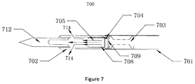
- FIG. 7 shows another arrow device with dual destructive function 700 in which the object to be fired is provided at the arrowhead.
- An object to be fired 712 is designed with a hollow cavity at a bottom and the hollow cavity is connected to an arrowhead 702 .
- High temperature and pressure gas denoted by a reference number 714 and generated by explosion of gunpowder 605 and incompletely burnt gunpowder rush into the hollow cavity of the object to be fired 712 and push the object to be fired 712 forward again.
- the arrow device with dual destructive function 700 comprises an arrow body 701 , an inertial body 703 , a firing pin 704 , a primer 708 and a uniform force mechanism 709 .
Landscapes
- Engineering & Computer Science (AREA)
- General Engineering & Computer Science (AREA)
- Chemical & Material Sciences (AREA)
- Combustion & Propulsion (AREA)
- Portable Nailing Machines And Staplers (AREA)
- Drilling And Exploitation, And Mining Machines And Methods (AREA)
- Catching Or Destruction (AREA)
Abstract
Description
Claims (17)
Applications Claiming Priority (4)
| Application Number | Priority Date | Filing Date | Title |
|---|---|---|---|
| CN201610090893.2 | 2016-02-05 | ||
| CN201610090893.2A CN105674810A (en) | 2016-02-05 | 2016-02-05 | Secondary killing arrow device |
| CN201610090893 | 2016-02-05 | ||
| PCT/CN2016/000196 WO2017132782A1 (en) | 2016-02-05 | 2016-04-14 | An arrow device with dual destructive function |
Publications (2)
| Publication Number | Publication Date |
|---|---|
| US20190041174A1 US20190041174A1 (en) | 2019-02-07 |
| US10690460B2 true US10690460B2 (en) | 2020-06-23 |
Family
ID=56304629
Family Applications (1)
| Application Number | Title | Priority Date | Filing Date |
|---|---|---|---|
| US16/075,047 Active US10690460B2 (en) | 2016-02-05 | 2016-04-14 | Arrow device with dual destructive function |
Country Status (3)
| Country | Link |
|---|---|
| US (1) | US10690460B2 (en) |
| CN (1) | CN105674810A (en) |
| WO (1) | WO2017132782A1 (en) |
Families Citing this family (1)
| Publication number | Priority date | Publication date | Assignee | Title |
|---|---|---|---|---|
| CN106442110A (en) * | 2016-10-14 | 2017-02-22 | 安徽理工大学 | Secondary impact bullet for Hopkinson bar |
Citations (11)
| Publication number | Priority date | Publication date | Assignee | Title |
|---|---|---|---|---|
| US3580172A (en) * | 1968-11-27 | 1971-05-25 | Grover E Hendricks | Underwater projectile for firing a cartridge upon impact |
| US4729320A (en) * | 1987-05-27 | 1988-03-08 | R. Larry Phillips | Combustion exhaust arrowhead |
| US4762328A (en) * | 1986-03-05 | 1988-08-09 | Beyl James A | Arrowhead with refillable cartridges for high impact arrows |
| JPH10165077A (en) | 1996-12-13 | 1998-06-23 | Hosoya Kako Kk | Arrow emitting light and sound |
| US6311623B1 (en) * | 1997-09-02 | 2001-11-06 | Wenzel Zaruba | Power-packed arrowhead |
| US20100197430A1 (en) * | 2004-06-17 | 2010-08-05 | Martin John C | Projectile launched media reservoir |
| US8241157B2 (en) * | 2009-12-28 | 2012-08-14 | Scott Russell | Projectile impact system |
| CN202533008U (en) | 2012-03-28 | 2012-11-14 | 黄刚 | Hunting arrowhead |
| US20130123051A1 (en) | 2010-12-16 | 2013-05-16 | Rac Em Bac, L.L.C. | Ammunition Delivery System Arrowhead and Method of Use |
| US20140296007A1 (en) | 2010-12-16 | 2014-10-02 | Rac Em Bac, L.Lc. | Ammunition delivery system arrowhead and method of use |
| CN205373548U (en) | 2016-02-05 | 2016-07-06 | 田悦丰 | Secondary kills and wounds arrow device |
Family Cites Families (4)
| Publication number | Priority date | Publication date | Assignee | Title |
|---|---|---|---|---|
| GB1361983A (en) * | 1970-07-24 | 1974-07-30 | Dynamit Nobel Ag | Explosive charges having ignition characteristics |
| EP0238155A1 (en) * | 1986-01-06 | 1987-09-23 | Carlos Roberto Emilio Lamm | Ammunition for firearms |
| CN202066429U (en) * | 2011-05-09 | 2011-12-07 | 河北卫星民爆器材有限公司 | Safety explosion-eliminating water gun shot |
| US20160025468A1 (en) * | 2014-07-22 | 2016-01-28 | Raytheon Company | Low-collateral damage directed fragmentation munition |
-
2016
- 2016-02-05 CN CN201610090893.2A patent/CN105674810A/en active Pending
- 2016-04-14 WO PCT/CN2016/000196 patent/WO2017132782A1/en active Application Filing
- 2016-04-14 US US16/075,047 patent/US10690460B2/en active Active
Patent Citations (12)
| Publication number | Priority date | Publication date | Assignee | Title |
|---|---|---|---|---|
| US3580172A (en) * | 1968-11-27 | 1971-05-25 | Grover E Hendricks | Underwater projectile for firing a cartridge upon impact |
| US4762328A (en) * | 1986-03-05 | 1988-08-09 | Beyl James A | Arrowhead with refillable cartridges for high impact arrows |
| US4729320A (en) * | 1987-05-27 | 1988-03-08 | R. Larry Phillips | Combustion exhaust arrowhead |
| JPH10165077A (en) | 1996-12-13 | 1998-06-23 | Hosoya Kako Kk | Arrow emitting light and sound |
| US6311623B1 (en) * | 1997-09-02 | 2001-11-06 | Wenzel Zaruba | Power-packed arrowhead |
| US20100197430A1 (en) * | 2004-06-17 | 2010-08-05 | Martin John C | Projectile launched media reservoir |
| US8241157B2 (en) * | 2009-12-28 | 2012-08-14 | Scott Russell | Projectile impact system |
| US20130123051A1 (en) | 2010-12-16 | 2013-05-16 | Rac Em Bac, L.L.C. | Ammunition Delivery System Arrowhead and Method of Use |
| US20140296007A1 (en) | 2010-12-16 | 2014-10-02 | Rac Em Bac, L.Lc. | Ammunition delivery system arrowhead and method of use |
| US9297624B2 (en) * | 2010-12-16 | 2016-03-29 | Rac Em Bac, L.L.C. | Ammunition delivery system arrowhead and method of use |
| CN202533008U (en) | 2012-03-28 | 2012-11-14 | 黄刚 | Hunting arrowhead |
| CN205373548U (en) | 2016-02-05 | 2016-07-06 | 田悦丰 | Secondary kills and wounds arrow device |
Non-Patent Citations (1)
| Title |
|---|
| International Search Report and Written Opinion as issued in connection with International Patent Application No. PCT/CN2016/000196, dated Oct. 28, 2016. |
Also Published As
| Publication number | Publication date |
|---|---|
| WO2017132782A1 (en) | 2017-08-10 |
| CN105674810A (en) | 2016-06-15 |
| US20190041174A1 (en) | 2019-02-07 |
Similar Documents
| Publication | Publication Date | Title |
|---|---|---|
| US4648324A (en) | Projectile with enhanced target penetrating power | |
| US8387540B2 (en) | Interceptor projectile and method of use | |
| US20090173250A1 (en) | System for protection against missiles | |
| US9366508B2 (en) | System for protection against missiles | |
| JPH11132697A (en) | Penetration projective with many collision sections including explosive section | |
| US9127920B2 (en) | Pyrotechnic slug | |
| DK3234496T3 (en) | BLAST HEAD FOR GENERATING AN EXPLOSION IN AN EXTENSION OF A TARGET SURFACE | |
| JP2004501339A (en) | Self-propelled projectile with penetrating core | |
| US7152532B2 (en) | Projectile with a sub-caliber penetrator core | |
| US10690460B2 (en) | Arrow device with dual destructive function | |
| RU2439473C1 (en) | Self-propelled projectile of guided type | |
| US8297190B1 (en) | Door breaching device with radially expandable explosive | |
| KR102041828B1 (en) | Projectile having high explosive and submunition | |
| CN205373548U (en) | Secondary kills and wounds arrow device | |
| JP6806712B2 (en) | Reactive armor | |
| CN113686207A (en) | Armor piercing composite bullet with transverse bursting | |
| RU2738687C2 (en) | Armor-pierced finned sub-caliber projectile | |
| RU2800674C1 (en) | Rocket projectile with a penetrating warhead | |
| EA034385B1 (en) | Fragmentation shot with ready destructive elements | |
| JP2000337800A (en) | Shot and warhead | |
| RU2705672C1 (en) | Ammunition | |
| KR20100010026U (en) | Training field firing shell | |
| RU2247931C1 (en) | Cluster ammunition "aspid" with fragmentation double-action live components | |
| RU2237231C1 (en) | Fragmentation-cluster shell "perun" | |
| JP2870722B2 (en) | Anti-armored flying object |
Legal Events
| Date | Code | Title | Description |
|---|---|---|---|
| FEPP | Fee payment procedure |
Free format text: ENTITY STATUS SET TO UNDISCOUNTED (ORIGINAL EVENT CODE: BIG.); ENTITY STATUS OF PATENT OWNER: MICROENTITY |
|
| FEPP | Fee payment procedure |
Free format text: ENTITY STATUS SET TO SMALL (ORIGINAL EVENT CODE: SMAL); ENTITY STATUS OF PATENT OWNER: MICROENTITY Free format text: ENTITY STATUS SET TO MICRO (ORIGINAL EVENT CODE: MICR); ENTITY STATUS OF PATENT OWNER: MICROENTITY |
|
| STPP | Information on status: patent application and granting procedure in general |
Free format text: DOCKETED NEW CASE - READY FOR EXAMINATION |
|
| STPP | Information on status: patent application and granting procedure in general |
Free format text: NON FINAL ACTION MAILED |
|
| STPP | Information on status: patent application and granting procedure in general |
Free format text: RESPONSE TO NON-FINAL OFFICE ACTION ENTERED AND FORWARDED TO EXAMINER |
|
| STPP | Information on status: patent application and granting procedure in general |
Free format text: FINAL REJECTION MAILED |
|
| STPP | Information on status: patent application and granting procedure in general |
Free format text: RESPONSE AFTER FINAL ACTION FORWARDED TO EXAMINER |
|
| STPP | Information on status: patent application and granting procedure in general |
Free format text: PUBLICATIONS -- ISSUE FEE PAYMENT VERIFIED |
|
| STCF | Information on status: patent grant |
Free format text: PATENTED CASE |
|
| MAFP | Maintenance fee payment |
Free format text: PAYMENT OF MAINTENANCE FEE, 4TH YEAR, MICRO ENTITY (ORIGINAL EVENT CODE: M3551); ENTITY STATUS OF PATENT OWNER: MICROENTITY Year of fee payment: 4 |