US10606697B2 - Method and apparatus for improved data recovery in data storage systems - Google Patents
Method and apparatus for improved data recovery in data storage systems Download PDFInfo
- Publication number
- US10606697B2 US10606697B2 US16/014,999 US201816014999A US10606697B2 US 10606697 B2 US10606697 B2 US 10606697B2 US 201816014999 A US201816014999 A US 201816014999A US 10606697 B2 US10606697 B2 US 10606697B2
- Authority
- US
- United States
- Prior art keywords
- matrix
- codewords
- long
- data
- vector
- Prior art date
- Legal status (The legal status is an assumption and is not a legal conclusion. Google has not performed a legal analysis and makes no representation as to the accuracy of the status listed.)
- Active, expires
Links
Images


Classifications
-
- G—PHYSICS
- G06—COMPUTING; CALCULATING OR COUNTING
- G06F—ELECTRIC DIGITAL DATA PROCESSING
- G06F11/00—Error detection; Error correction; Monitoring
- G06F11/07—Responding to the occurrence of a fault, e.g. fault tolerance
- G06F11/08—Error detection or correction by redundancy in data representation, e.g. by using checking codes
- G06F11/10—Adding special bits or symbols to the coded information, e.g. parity check, casting out 9's or 11's
- G06F11/1008—Adding special bits or symbols to the coded information, e.g. parity check, casting out 9's or 11's in individual solid state devices
- G06F11/1068—Adding special bits or symbols to the coded information, e.g. parity check, casting out 9's or 11's in individual solid state devices in sector programmable memories, e.g. flash disk
-
- G—PHYSICS
- G06—COMPUTING; CALCULATING OR COUNTING
- G06F—ELECTRIC DIGITAL DATA PROCESSING
- G06F11/00—Error detection; Error correction; Monitoring
- G06F11/07—Responding to the occurrence of a fault, e.g. fault tolerance
- G06F11/08—Error detection or correction by redundancy in data representation, e.g. by using checking codes
- G06F11/10—Adding special bits or symbols to the coded information, e.g. parity check, casting out 9's or 11's
- G06F11/1008—Adding special bits or symbols to the coded information, e.g. parity check, casting out 9's or 11's in individual solid state devices
- G06F11/1012—Adding special bits or symbols to the coded information, e.g. parity check, casting out 9's or 11's in individual solid state devices using codes or arrangements adapted for a specific type of error
-
- G—PHYSICS
- G06—COMPUTING; CALCULATING OR COUNTING
- G06F—ELECTRIC DIGITAL DATA PROCESSING
- G06F11/00—Error detection; Error correction; Monitoring
- G06F11/07—Responding to the occurrence of a fault, e.g. fault tolerance
- G06F11/08—Error detection or correction by redundancy in data representation, e.g. by using checking codes
- G06F11/10—Adding special bits or symbols to the coded information, e.g. parity check, casting out 9's or 11's
- G06F11/1076—Parity data used in redundant arrays of independent storages, e.g. in RAID systems
-
- G—PHYSICS
- G11—INFORMATION STORAGE
- G11C—STATIC STORES
- G11C29/00—Checking stores for correct operation ; Subsequent repair; Testing stores during standby or offline operation
- G11C29/52—Protection of memory contents; Detection of errors in memory contents
-
- H—ELECTRICITY
- H03—ELECTRONIC CIRCUITRY
- H03M—CODING; DECODING; CODE CONVERSION IN GENERAL
- H03M13/00—Coding, decoding or code conversion, for error detection or error correction; Coding theory basic assumptions; Coding bounds; Error probability evaluation methods; Channel models; Simulation or testing of codes
- H03M13/29—Coding, decoding or code conversion, for error detection or error correction; Coding theory basic assumptions; Coding bounds; Error probability evaluation methods; Channel models; Simulation or testing of codes combining two or more codes or code structures, e.g. product codes, generalised product codes, concatenated codes, inner and outer codes
- H03M13/2906—Coding, decoding or code conversion, for error detection or error correction; Coding theory basic assumptions; Coding bounds; Error probability evaluation methods; Channel models; Simulation or testing of codes combining two or more codes or code structures, e.g. product codes, generalised product codes, concatenated codes, inner and outer codes using block codes
-
- H—ELECTRICITY
- H03—ELECTRONIC CIRCUITRY
- H03M—CODING; DECODING; CODE CONVERSION IN GENERAL
- H03M13/00—Coding, decoding or code conversion, for error detection or error correction; Coding theory basic assumptions; Coding bounds; Error probability evaluation methods; Channel models; Simulation or testing of codes
- H03M13/37—Decoding methods or techniques, not specific to the particular type of coding provided for in groups H03M13/03 - H03M13/35
- H03M13/373—Decoding methods or techniques, not specific to the particular type of coding provided for in groups H03M13/03 - H03M13/35 with erasure correction and erasure determination, e.g. for packet loss recovery or setting of erasures for the decoding of Reed-Solomon codes
-
- H—ELECTRICITY
- H03—ELECTRONIC CIRCUITRY
- H03M—CODING; DECODING; CODE CONVERSION IN GENERAL
- H03M13/00—Coding, decoding or code conversion, for error detection or error correction; Coding theory basic assumptions; Coding bounds; Error probability evaluation methods; Channel models; Simulation or testing of codes
- H03M13/61—Aspects and characteristics of methods and arrangements for error correction or error detection, not provided for otherwise
- H03M13/615—Use of computational or mathematical techniques
- H03M13/616—Matrix operations, especially for generator matrices or check matrices, e.g. column or row permutations
Definitions
- the present invention relates to the field of digital storage systems and more specifically to improving the error correction capabilities of data storage systems.
- RAID storage systems have been used for years to redundantly store large amounts of data, used in applications such as online storage.
- Error Correcting Codes have been developed that recover erasures of stored data (as opposed to errors).
- Some codes such as the well-known Reed-Solomon code, are forward error correction (FEC) codes that transform messages of k bits into longer codewords of n symbols such that the original message can be recovered from a subset of the n symbols.
- FEC forward error correction
- Codewords are stored on a number of independent storage media, such as pages in a flash memory, blocks, LUNs, Planes or Medium, any of which can be considered to have independent error statistics.
- an i th media may store an i th codeword v i encoded using a generator matrix Gi and decoded using a corresponding parity check matrix H i , where 1 ⁇ i ⁇ m.
- each codeword is XORed with each other prior to storage, forming a parity codeword v m+1 .
- any single codeword v i fails, 1 ⁇ i ⁇ m+1, it is recovered by performing an XOR function of all the remaining m successfully-decoded codewords ⁇ v i1 , v i2 , . . . , v im ⁇ . Such a scheme cannot recover more than one failed medium.
- a method comprising generating a plurality of data blocks from a quantity of unencoded data, receiving, by a plurality of encoders, a respective one of the plurality of data blocks, encoding the plurality of data blocks by the plurality of encoders, respectively, to generate a plurality of codewords, logically combining the plurality of codewords to generate an encoded parity block, storing the plurality of codewords and the encoded parity block in a plurality of data storage media, respectively, retrieving the plurality of codewords and the encoded parity block from the data storage media, and decoding each of the plurality of codewords.
- generating a long vector from the plurality of codewords and the encoded parity block and decoding the long vector using a long parity check matrix to re-create the data blocks.
- a data retrieval system comprising plurality of decoders, a memory for storing processor-executable instructions and a long parity check matrix, and a processor coupled to the plurality of decoders and the memory for executing the processor-executable instructions that causes the data retrieval system to retrieve, by the plurality of decoders, a plurality of codewords from a plurality of data storage media, respectively, and decode each of the plurality of codewords by the plurality of decoders.
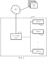
- FIG. 1 is a block diagram of one embodiment of a data storage and retrieval system for storing and retrieving data with increased data recovery characteristics
- FIG. 2 is a block diagram of one embodiment of an encoder portion of the data storage and retrieval system as shown in FIG. 1 ;
- FIG. 3 is a block diagram of one embodiment of a decoder portion of the data storage and retrieval system as shown in FIG. 1 ;
- FIGS. 4A and 4B are flow diagrams illustrating one embodiment of a method performed by the data storage and retrieval system as shown in FIG. 1 to store and retrieve data with increased data recovery characteristics.
- circuits, systems, networks, processes, and other components may be shown as components in block diagram form in order not to obscure the embodiments in unnecessary detail.
- well-known circuits, processes, algorithms, structures, and techniques may be shown without unnecessary detail in order to avoid obscuring the embodiments.
- individual embodiments may be described as a process which is depicted as a flowchart, a flow diagram, a data flow diagram, a structure diagram, or a block diagram. Although a flowchart may describe the operations as a sequential process, many of the operations can be performed in parallel or concurrently. In addition, the order of the operations may be re-arranged.
- a process is terminated when its operations are completed, but could have additional steps not included in a figure.
- a process may correspond to a method, a function, a procedure, a subroutine, a subprogram, etc. When a process corresponds to a function, its termination can correspond to a return of the function to the calling function or the main function.
- computer-readable medium includes, but is not limited to, portable or non-portable storage devices, optical storage devices, and various other mediums capable of storing, containing, or carrying instruction(s) and/or data.
- a computer-readable medium may include a non-transitory medium in which data can be stored and that does not include carrier waves and/or transitory electronic signals propagating wirelessly or over wired connections. Examples of a non-transitory medium may include, but are not limited to, a magnetic disk or tape, optical storage media such as compact disk (CD) or digital versatile disk (DVD), flash memory, RAM, ROM, etc.
- a computer-readable tedium may have stored thereon code and/or machine-executable instructions that may represent a procedure, a function, a subprogram, a program, a routine, a subroutine, a module, a software package, a class, or any combination of instructions, data structures, or program statements.
- a code segment may be coupled to another code segment or a hardware circuit by passing and/or receiving information, data, arguments, parameters, or memory contents.
- Information, arguments, parameters, data, etc. may be passed, forwarded, or transmitted via any suitable means including memory sharing, message passing, token passing, network transmission, or the like.
- embodiments may be implemented by hardware, software, firmware, middleware, microcode, hardware description languages, or any combination thereof.
- the program code or code segments to perform the necessary tasks may be stored in a computer-readable or machine-readable medium.
- a processor(s) may perform the necessary tasks.
- the embodiments described herein provide specific improvements to a data storage system.
- the embodiments allow the storage system to recover more data in the event of erasures or errors due to, for example, media failures or noise.
- FIG. 1 is a simplified block diagram of one embodiment of a data storage and retrieval system 100 used for storing large amounts of data in accordance with the teachings herein.
- numerous hosts 102 provide unencoded data to data storage server 104 via wide-area network 106 , such as the Internet, and data storage server 104 processes the data for storage in a plurality of data storage media 108 a - 108 m .
- data storage systems are used in cloud storage models, in which digital data may be stored in logical pools, physical storage may span multiple servers (and often locations), and the physical environment is typically owned and managed by a hosting company. These cloud storage providers are responsible for keeping the data available and accessible, and the physical environment protected and running. People and organizations buy or lease storage capacity from the providers to store user, organization, or application data.
- Example of such cloud storage include Amazon's S3, Google's Cloud Storage and Microsoft's Azure storage platforms.
- the data received from hosts 102 is stored in data storage media 108 using forward error correcting codes to mathematically calculate extra redundant data.
- data storage and retrieval system 100 may, in addition, replicate data for redundant storage. Erasure encoding and replication are well-known methods for protecting data from loss, due to noisy transmission channels or failure of one or more storage media.
- FIG. 2 is a block diagram of one embodiment of an encoder portion of data storage and retrieval system 100 .
- Processor 200 executes processor-executable instructions stored in memory 202 to store data in accordance with the teachings herein. Some of the functionality to store and retrieve data may be performed by processor 200 , while others may be performed by the various functional blocks shown in FIG. 2 .
- Each of the functional components shown in FIG. 2 may be integrated into a custom integrated circuit, such as an Application Specific Integrated Circuit (ASIC) or a custom System on a Chip (SoC). In other embodiments, one or more of the components shown in FIG. 2 may be integrated into one or more custom integrated circuits, while other functional components may comprise integrated circuits, discreet components, or a combination thereof.
- ASIC Application Specific Integrated Circuit
- SoC System on a Chip
- Processor 200 comprises one or more microprocessors, microcontrollers and/or custom or custom integrated circuits, and/or discrete components able to carry out the functionality required for operation of data storage and retrieval system 100 .
- Processor 400 may be selected based on processing capabilities, power-consumption properties, and/or cost and size considerations.
- Memory 202 comprises one or more information storage devices, such RAM, ROM, Flash, and/or virtually any other type of electronic memory device. Typically, memory 202 comprises more than one type of memory. For example, a ROM may be used to store static processor-executable instructions, while a RAM memory or flash memory may be used to store variable data. Memory 202 may be used to store a variety of matrices used to encode and decode data.
- Data from hosts 102 is provided to input data transfer logic 200 , typically via wide-area network 104 , where input data transfer logic 200 may apportion a predetermined number of bits, bytes or symbols of the data (i.e., “segments”) into a plurality of m unencoded data blocks, each data block comprising a predetermined number of bits, bytes or symbols and, in general, k bits.
- Input data transfer logic 200 comprises circuitry for receiving data from a large number of hosts 102 , such as cellular telephones, personal computers, cloud-based servers, etc.
- the unencoded data blocks u i are typically generated in parallel as data is received by input data transfer logic 200 . In the example shown in FIG.
- a predetermined number of bits, bytes or symbols of the data is apportioned into in data blocks (where m>2), and the data blocks are provided to encoders 202 a - 202 m , respectively. It should be understood that in other embodiments, fewer encoders may be used to encode the data blocks. For example, if four parallel data blocks are generated by input data transfer logic 200 , two encoders could be used to encode the data blocks, each encoder responsible for encoding two of the four data blocks.
- Encoders 202 a - 202 m each comprise a forward error correction encoder, such as a low-density parity check (LDPC) encoder that encodes the data blocks using a low-density generator matrix G.
- LDPC low-density parity check
- each of the encoders uses the same G matrix to encode respective data blocks, while in another embodiment, two or more of the encoders use different G matrices.
- Encoders 202 a - 202 m generate encoded data blocks, or codewords, respectively, where 2 ⁇ i ⁇ m, and the codewords v i from each encoder is stored in a respective independent data storage media 108 a - 108 m , respectively.
- Data storage media 108 a - 108 m comprises two or more independent hard drives, solid state drives, pages in a memory device, logical unit numbers (LUNs), or any other electronic, optical or mechanical information storage device or portion thereof.
- Each data storage media 108 typically comprises different error statistics, i.e., the likelihood of a failure due to factors such as technology, age, temperature, or humidity.
- data storage media 108 are part of data storage and retrieval system 100 and co-located therewith, for example, as part of a rack-mounted data storage system located in a physical data center. In other embodiments, one or more of the data storage media 108 are remotely located from data storage server 104 , for example, located in a different physical location than data storage server 104 and accessed via the Internet.
- the codewords v i are additionally used to create a parity codeword v m+1 by logically combining the codewords from each of the encoders by logic circuitry 208 .
- Logic circuitry 208 typically comprises hardware and/or firmware to combine the codewords using an exclusive OR, or XOR, function on a bit-wise basis.
- the parity codeword can be used to recover from erasures when retrieving the codewords from the data storage units 108 by XORing the parity codeword with each of the available codewords from data storage units 108 , as will be explained in greater detail later herein.
- Each encoders 202 a - 202 m generates codewords, each comprising information bits and parity bits, and each having a length greater than the data block.
- R the encoding rate
- n the length of each codeword
- k the length of the original, unencoded data block.
- the codewords are generated as a result of applying a generator matrix G to each of the data blocks, in an embodiment where encoders comprise LDPC encoders.
- FIG. 3 is a block diagram of one embodiment of a decoder portion of data storage and retrieval system 100 .
- processor 200 executes processor-executable instructions stored in memory 202 , in this case to retrieve data from data storage media 108 in accordance with the teachings herein. Some of the functionality to retrieve data may be performed by processor 200 , while others may be performed by the various functional blocks shown in FIG. 3 .
- M codewords are retrieved, generally in parallel, from data storage media 108 a - 108 m .
- the codewords are each decoded using an independent decoder 300 a - 300 m , respectively. In other embodiments, a fewer number of decoders may be used to decode the m codewords.
- An i th decoder 300 applies an H parity check matrix to the codewords, respectively, to re-create data blocks u i .
- the H parity check matrix used by the decoders may all be the same, or two or more may be different from one another, depending on whether different generator matrices G were used to encode the data.
- Each of the decoders uses an iterative decoding technique, such as a message passing algorithm, that is then used by each decoder to try and re-create the data words u i , respectively.
- the decoder shown in FIG. 3 can detect and correct errors caused by failed storage media and/or noise in the channel between the storage media and the decoders 300 a - 300 m in three ways.
- errors from each data storage media may be corrected by decoders 300 a - 300 m , respectively. That is, decoder 300 a may be able to correct errors due to noise in the transmission medium between data storage media 108 a and decoder 300 a using well-known error correction decoding techniques, such as the use of LDPC decoding techniques. As previously mentioned, each of decoders 300 a - 300 m utilizes an iterative decoding technique, such as a message passing algorithm, to provide hard or soft decoding of a respective codeword.
- erasures may be detected and corrected using logic circuitry 302 , when one of the data storage media fail.
- Logic circuitry 302 comprises hardware and/or firmware to combine the codewords from all of the other data storage media plus parity media 108 m+1 using an exclusive OR, or XOR, function on a bit-wise basis.
- the decoded codeword, data block u r is provided to output data transfer logic 304 , where it is combined with the other successfully decoded data blocks to form the original data provided by one of the host(s) 102 .
- errors from any of the data storage media may be detected and corrected by constructing a “long vector” v L as a way to utilize information in all of the received codewords to aid in the error detection and correction process.
- the long vector v L is formed as a concatenation of the m individual codewords and v m+1 as they are generated by encoders 206 a - 206 m and logic circuitry 208 during the encoding process.
- v L may be expressed as:
- G 1 , G 2 . . . G m are each a different generator matrix used by respective ones of the encoders 206 a - 206 m to encode data blocks u 1 -u m , respectively.
- G L may be defined as:
- G L [ G 1 0 ... G 1 0 G 2 ... G 2 ⁇ 0 ... G m G m ]
- G i G, 1 ⁇ i ⁇ m
- I m is an m ⁇ m identity matrix
- 1 m is an (m ⁇ 1)-long column vector of all 1s
- G is the generator matrix common to all the encoders
- the vertical bar denotes a partition of the matrix
- ⁇ represents a tensor product function. Since the vector v m+1 is simply a linear combination of codewords v 1 , v 2 , . . . , v m , each generated from the same generator matrix G, v m+1 itself is a codeword in the space of codewords generated by G, and, as such, could be decoded using the decoding algorithm used to decode v i , where 1 ⁇ i ⁇ m.
- a and B are tensor products of two matrices A and B of size (m ⁇ n) and (p ⁇ q) respectively, the tensor product between them, denoted by A ⁇ B, is defined as follows: every element of A individually multiplies the whole matrix B and, therefore, the size of the resulting matrix is (mp ⁇ nq). Note that A and B need not be matrix-multiplication-compatible in the conventional sense to compute their tensor product. For example, if:
- a ⁇ B [ 1 ⁇ B 0 ⁇ B 1 ⁇ B 0 ⁇ B 1 ⁇ B 1 ⁇ B ]
- a long parity check matrix H L may be formed to decode data blocks encoded using the long G L matrix.
- Such a H L matrix is formed such that G L *H′ L is an all-zero matrix of size mk ⁇ n(m+1) ⁇ mk, which ensures that v L is a codeword generated from G L , allowing decoding of v L using the H L matrix.
- the vector v m+1 is an XOR-combination of individual codewords generated by encoders 206 a - 206 m using the same generator matrix G, it does not contain any independent bits, and as such, could potentially constitute some of the parity bits of v L . Since the only independent bits in constructing v L using G L are ⁇ u 1 , u 2 , . . . u m ⁇ , where each u i is k-bits long, 1 ⁇ i ⁇ m, assuming that an H L exists for G L , the code rate R L of the long codeword v L is given by
- G*H′ yields a 2 ⁇ 2 all-zero matrix, as expected.
- G L may now be formed as a matrix having 6 rows and 16 columns:
- v L can be determined simply by concatenating each of the codewords v 1 , v 2 , and v 3 , with v 4 , where v 4 is equal to v 1 ⁇ v 2 ⁇ v 3 .
- the term “concatenating” as used herein, is to form a row vector comprising codewords arranged ins successive alignment.
- decoder 300 L uses a long parity check matrix H L to decode the long vector v L .
- H L [ H 0 ... 0 0 0 H ... 0 0 ⁇ 0 0 ... H 0 I n I n ... I n I n ]
- H L can be written in tensor product notation as:
- H L [ [ I m ⁇ 0 m ] ⁇ H 1 m + 1 ′ ⁇ I n ]
- I m is an m ⁇ m identity matrix
- 0 m is a column vector of all 0's of length m
- 1′ m+1 is a row vector of all 1's of length (m+1)
- I n is an n ⁇ n identity matrix.
- the vertical bar denotes a partition of the matrix, i.e., I m is augmented with 0 m .
- v L can be made systematic using one of two methods, to form v LS .
- a systematic generator matrix G LS is formed, based on G L , by placing the columns in G L that correspond to the information bits of each codeword to one end of the G LS matrix. Then, G LS is applied to a concatenation of the information bits of each of the codewords, or a concatenation of the data blocks themselves, as explained previously.
- the long codeword v L can be made systematic even if it is formed using G L , by rearranging the information bits in v L so that they occupy either the least significant bits or the most significant bits of v LS .
- G LS [PL
- H LS [I n ⁇ k
- PL′] [I 10
- the parity check bits in it i.e., bits 1-10, from the left, are the concatenation of the parity check bits of the codewords (i.e., the first two bits of each codeword), plus the entire codeword v 4 , generated as the XOR of codewords v 1 , v 2 , and v 3 .
- processor 200 a more efficient way of generating the systematic version of the long codeword v L , by simply concatenating the parity bits from each codeword, followed by the XOR-ed version of the individual codewords, and then appending a concatenation of the information bits from the individual codewords.
- n is the number of bits in each codeword
- m is the number of data blocks/codewords generated from each data segment received from host 102
- k is the number of bits in each data block
- I m is an m ⁇ m identity matrix
- 1 m is a column vector of all 1's having a length m
- P is a portion of G that generates the parity bits of a codeword
- I km is an identity matrix of k ⁇ m rows and columns.
- Q is a matrix comprising a tensor product of a) a matrix comprising I m augmented with a column vector of all 1's of length m, and b) a matrix comprising P k(n ⁇ k) augmented with a tensor product of the column vector of all 1's of length m and an identity matrix having k ⁇ m rows and columns.
- H LS I n(m+1) ⁇ km
- H is a low-density parity check (LDPC) matrix
- LDPC low-density parity check
- H is an LDPC matrix
- a particular scheduling can be used to decode v L using the message-passing decoding algorithm executed by decoder 300 L, by taking advantage of the fact that only the last n rows of H L have 1's in them that span all the m individual codewords: each of those rows has (m+1) 1's in it.
- Decoder 300 L can periodically update the log-likelihood-ratio (LLR) values of the bits connected to each of those parity check bits based on the LLR values that were handed to them from the individual codewords at that time. The updated LLR values can then be used by the decoders to continue their decoding.
- LLR log-likelihood-ratio
- the codebits in one of the data storage media interact with, or obtain information from, codebits stored in other data storage media at regular time intervals, not continuously in every iteration.
- Such a scheduling can also be used in decoding v L using H L .
- FIG. 4 is a flow diagram illustrating one embodiment of a method performed by data storage and retrieval system 100 to store and retrieve data with increased data recovery characteristics.
- the method is implemented by one or more processors, executing processor-executable instructions stored in one or more memories, such as processor 200 and memory 202 , respectively. It should be understood that in some embodiments, not all of the steps shown in FIG. 4 are performed and that the order in which the steps are carried out may be different in other embodiments. It should be further understood that some minor method steps have been omitted for purposes of clarity.
- information may be pre-stored in memory 202 and/or the memory of the encoders and/or decoders in order to encode data blocks and decode codewords.
- a parity check matrix H a long parity check matrix H L , a long systematic parity check matrix H LS , a generator matrix G, a long generator matrix G L , and a long systematic generator matrix H LS may be stored.
- data is received by input data transfer logic 204 from one of numerous hosts 102 remotely coupled to data storage and retrieval system 100 , typically via the Internet.
- a predetermined amount of the data from host 102 is divided into m, equal-sized data blocks, generally provided in parallel to a plurality of encoders 206 a - 206 m by input data transfer logic 204 .
- Each of the data blocks comprises k bits.
- each encoder 206 a - 206 m encodes a respective one of the data blocks using, in one embodiment, LDPC encoding, each encoder 206 a - 206 m using the same generator matrix G stored in memory 202 or locally by each of the encoders.
- the result is a plurality of codewords, each comprising k information bits and m parity bits, where m is the number of codewords generated for each segment of unencoded data from host 102 .
- each of the codewords are made systematic by a respective encoder.
- each of the codewords from the encoders are logically combined with each other using an XOR function, as provided by logic circuitry 208 , to generate a parity codeword having a length equal to the length of each of the codewords.
- each of the codewords are stored in data storage media 108 a - 108 m
- the parity codeword is stored in data storage media 108 m+1 .
- Each of the data storage media may be co-located with data storage server 104 or they may be remotely distributed in the cloud.
- one of the hosts 102 requests retrieval of data that was previously provided to data storage and retrieval system 100 .
- a set of codewords are retrieved in parallel from data storage media 108 a - 108 m.
- each codeword retrieved from the data storage media are provided to a respective one of the decoders 300 a - 300 m .
- each of the decoders decodes a respective one of the codewords using the same parity check matrix H, stored in memory 202 or locally by each of the decoders.
- An iterative two-step decoding algorithm known as a message passing algorithm may be employed by each of the decoders, where a number of check nodes are first updated based on messages received from all or some variable nodes. In a second step, all or some of the variable nodes may be updated based on messages received from all or some of the check nodes. The process may be repeated until either a codeword has been decoded or until a threshold number of iterations or sub-iterations has been reached.
- the messages used in message passing algorithm may be log-likelihood-ratio (LLR) messages, also known as soft information.
- LLR log-likelihood-ratio
- the Iterative decoders 300 a - 300 m may calculate the LLR messages to correct Or detect errors in a received codeword.
- each of the variable nodes may receive an LLR message based on information from the original codeword as provided to any one of the decoders 300 a - 300 m.
- the result of the iterative decoding process is a re-creation of the original data blocks created at block 404 , assuming that each codeword is decoded without errors.
- each of the decoded codewords is provided to output data transfer logic 304 , where they are combined to re-create the original data that was provided by the requesting host 102 .
- traditional XOR techniques may be used to recover the “bad” codeword.
- processor 300 creates V L as a concatenation of codewords v 1 -v m plus the result of an XOR function of all of the codewords v 1 -v m .
- v L may be created by multiplying each of the data blocks u 1 -u m by a long generator matrix G L stored in memory 202 or by decoder 300 L, as discussed previously.
- v L may be made systematic (v LS ) by processor 200 , by multiplying a systematic generator matrix G LS by an information vector comprising a concatenation of data blocks u 1 -u m .
- the G LS may be formed from the G L matrix by processor 200 or decoder 300 L, or it may be pre-stored in memory 202 or a memory of decoder 300 L.
- G LS is formed by re-arranging the columns of the G L matrix, by placing the columns in G L that correspond to the information bits of each codeword to one end of the G LS matrix.
- v L can be made systematic if it is formed using G L , by rearranging the information bits in v L so that they occupy either the least significant bits or the most significant bits of v LS .
- either the long vector v L or the long systematic vector v LS may be decoded by decoder 300 L.
- a long parity check matrix H L stored in either memory 202 or decoder 300 L, is applied to v L , using the iterative decoding process discussed above.
- a long, systematic parity check matrix H LS stored in either memory 202 or decoder 300 L, is applied to v LS , using the iterative decoding process discussed above.
- processor 200 or decoder 300 L periodically updates the log-likelihood-ratio (LLR) values of the bits connected to each of the parity check bits based on the LLR values that were provided to the parity check bits from the individual codewords at that time.
- LLR log-likelihood-ratio
- the updated LLR values are used by the individual decoders to continue their decoding.
- processor 200 determines whether the long vector was decoded correctly, using techniques well known in the art. If so, then each of the decoded codewords are provided to output data transfer logic 304 , where they are combined to form the original data segment that had been provided by one of the hosts 102 . The decoded codewords from decoders 300 a - 300 m are ignored. Thus, by creating the long vector and decoding it with a long parity check matrix, data storage and retrieval system 100 may be able to better tolerate errors and erasures, because the codebits of each codeword in the long vector interact with or obtain information from each other.
- the methods or algorithms described in connection with the embodiments disclosed herein may be embodied directly in hardware or embodied in processor-readable instructions executed by a processor.
- the processor-readable instructions may reside in RAM memory, flash memory, ROM memory, EPROM memory, EEPROM memory, registers, hard disk, a removable disk, a CD-ROM, or any other form of storage medium known in the art.
- An exemplary storage medium is coupled to the processor such that the processor can read information from, and write information to, the storage medium.
- the storage medium may be integral to the processor.
- the processor and the storage medium may reside in an ASIC.
- the ASIC may reside in a user terminal.
- the processor and the storage medium may reside as discrete components.
- an embodiment of the invention may comprise a computer-readable media embodying code or processor-readable instructions to implement the teachings, methods, processes, algorithms, steps and/or functions disclosed herein.
- the decoding apparatus and methods described herein may also be used in other communication situations and are not limited to RAID storage.
- compact disk technology also uses erasure and error-correcting codes to handle the problem of scratched disks and would benefit from the use of the techniques described herein.
- satellite systems may use erasure codes in order to trade off power requirements for transmission, purposefully allowing for more errors by reducing power and chain reaction coding would be useful in that application.
- erasure codes may be used in wired and wireless communication networks, such as mobile telephone/data networks, local-area networks, or the Internet. Embodiments of the current invention may, therefore, prove useful in other applications such as the above examples, where codes are used to handle the problems of potentially lossy or erroneous data.
Abstract
Description
G L=[I m|1m]⊗G
The higher the value of m, the closer RL is to R. The lower the value of m, the better its performance will be.
v 1=[1 1]*G=1 0 1 1;
v 2=[1 0]*G=1 1 1 0;
v 3=[0 1]*G=0 1 0 1;
v L=[1 1 1 0 0 1]*G L=[1 0 1 1 1 1 1 0 0 1 0 1 0 0 0 0]
G LS=((I m|1m)⊗P k(n−k))|((1m ⊗I n)|I km)
Q=(I m|1m)⊗P k(n−k)|(1m ⊗I m)
then
G LS =Q|I km.
H LS =I n(m+1)−km |Q′
Claims (17)
Priority Applications (3)
| Application Number | Priority Date | Filing Date | Title |
|---|---|---|---|
| US16/014,999 US10606697B2 (en) | 2018-06-21 | 2018-06-21 | Method and apparatus for improved data recovery in data storage systems |
| PCT/US2019/038479 WO2019246527A1 (en) | 2018-06-21 | 2019-06-21 | Method and apparatus for improved data recovery in data storage systems |
| TW108121796A TW202001920A (en) | 2018-06-21 | 2019-06-21 | Method and apparatus for improved data recovery in data storage systems |
Applications Claiming Priority (1)
| Application Number | Priority Date | Filing Date | Title |
|---|---|---|---|
| US16/014,999 US10606697B2 (en) | 2018-06-21 | 2018-06-21 | Method and apparatus for improved data recovery in data storage systems |
Publications (2)
| Publication Number | Publication Date |
|---|---|
| US20190391870A1 US20190391870A1 (en) | 2019-12-26 |
| US10606697B2 true US10606697B2 (en) | 2020-03-31 |
Family
ID=68981863
Family Applications (1)
| Application Number | Title | Priority Date | Filing Date |
|---|---|---|---|
| US16/014,999 Active 2038-07-05 US10606697B2 (en) | 2018-06-21 | 2018-06-21 | Method and apparatus for improved data recovery in data storage systems |
Country Status (3)
| Country | Link |
|---|---|
| US (1) | US10606697B2 (en) |
| TW (1) | TW202001920A (en) |
| WO (1) | WO2019246527A1 (en) |
Cited By (1)
| Publication number | Priority date | Publication date | Assignee | Title |
|---|---|---|---|---|
| US11949431B1 (en) * | 2022-12-29 | 2024-04-02 | Code-X, Inc. | Obfuscating data in distributed data storage systems and network communications |
Families Citing this family (3)
| Publication number | Priority date | Publication date | Assignee | Title |
|---|---|---|---|---|
| TWI757609B (en) * | 2018-08-03 | 2022-03-11 | 日商索尼股份有限公司 | Transmission apparatus and method, receiving apparatus and method for use in communication |
| TWI744960B (en) * | 2020-06-22 | 2021-11-01 | 旺宏電子股份有限公司 | Memory controller and memory devcie |
| CN114024594B (en) * | 2021-11-09 | 2023-10-20 | 北京中科晶上科技股份有限公司 | Communication method and device of satellite communication system |
Citations (18)
| Publication number | Priority date | Publication date | Assignee | Title |
|---|---|---|---|---|
| US6229458B1 (en) | 1999-08-27 | 2001-05-08 | Lsi Logic Corporation | Rate 32/34 (D=0, G=9/I=9) modulation code with parity for a recording channel |
| US20020007438A1 (en) | 1996-09-16 | 2002-01-17 | Hae-Seung Lee | Memory system for improving data input/output performance and method of caching data recovery information |
| US20040225944A1 (en) | 2003-05-09 | 2004-11-11 | Brueggen Christopher M. | Systems and methods for processing an error correction code word for storage in memory components |
| US20050193312A1 (en) | 2004-03-01 | 2005-09-01 | Smith Kenneth K. | System for error correction coding and decoding |
| US20070124652A1 (en) * | 2005-11-15 | 2007-05-31 | Ramot At Tel Aviv University Ltd. | Method and device for multi phase error-correction |
| US20080140686A1 (en) | 2006-12-08 | 2008-06-12 | Electronics And Telecommunications Research Institute | Parity check matrix storing method, block ldpc coding method, and apparatus using parity check matrix storing method |
| US20090217124A1 (en) * | 2008-02-21 | 2009-08-27 | Ramot At Tel-Aviv University Ltd. | Method and device for multi phase error-correction |
| US20090241008A1 (en) * | 2008-03-18 | 2009-09-24 | Samsung Electronics Co., Ltd. | Memory devices and encoding and/or decoding methods |
| US20100138720A1 (en) * | 2008-11-24 | 2010-06-03 | Samsung Electronics Co., Ltd. | Channel-encoding/decoding apparatus and method using low-density parity-check codes |
| US20110004812A1 (en) * | 2009-07-01 | 2011-01-06 | Silicon Motion, Inc. | Coder-decoder and method for encoding and decoding an error correction code |
| US8020063B2 (en) * | 2007-07-26 | 2011-09-13 | Harris Corporation | High rate, long block length, low density parity check encoder |
| US20110276855A1 (en) * | 2010-05-07 | 2011-11-10 | Samsung Electronics Co., Ltd. | Method and apparatus for channel coding and decoding in a communication system using a low-density parity-check code |
| US8261167B1 (en) * | 2009-03-09 | 2012-09-04 | Pmc-Sierra Us, Inc. | Cyclically interleaved dual BCH, with simultaneous decode and per-codeword maximum likelihood reconciliation |
| US9184832B2 (en) * | 2010-07-15 | 2015-11-10 | Fraunhofer-Gesellschaft Zur Foerderung Der Angewandten Forschung E.V. | Concept for combining coded data packets |
| US20160329913A1 (en) * | 2015-05-04 | 2016-11-10 | International Business Machines Corporation | Encoding and writing of data on multitrack tape |
| US9537508B1 (en) * | 2014-01-09 | 2017-01-03 | Marvell International Ltd. | Systems and methods for decoding cascade LDPC codes |
| US20190028117A1 (en) * | 2017-07-19 | 2019-01-24 | SK Hynix Inc. | Low-complexity ldpc encoder |
| US20190165809A1 (en) * | 2017-11-27 | 2019-05-30 | Goke Us Research Laboratory | Method and apparatus for efficient data decoding |
-
2018
- 2018-06-21 US US16/014,999 patent/US10606697B2/en active Active
-
2019
- 2019-06-21 WO PCT/US2019/038479 patent/WO2019246527A1/en active Application Filing
- 2019-06-21 TW TW108121796A patent/TW202001920A/en unknown
Patent Citations (18)
| Publication number | Priority date | Publication date | Assignee | Title |
|---|---|---|---|---|
| US20020007438A1 (en) | 1996-09-16 | 2002-01-17 | Hae-Seung Lee | Memory system for improving data input/output performance and method of caching data recovery information |
| US6229458B1 (en) | 1999-08-27 | 2001-05-08 | Lsi Logic Corporation | Rate 32/34 (D=0, G=9/I=9) modulation code with parity for a recording channel |
| US20040225944A1 (en) | 2003-05-09 | 2004-11-11 | Brueggen Christopher M. | Systems and methods for processing an error correction code word for storage in memory components |
| US20050193312A1 (en) | 2004-03-01 | 2005-09-01 | Smith Kenneth K. | System for error correction coding and decoding |
| US20070124652A1 (en) * | 2005-11-15 | 2007-05-31 | Ramot At Tel Aviv University Ltd. | Method and device for multi phase error-correction |
| US20080140686A1 (en) | 2006-12-08 | 2008-06-12 | Electronics And Telecommunications Research Institute | Parity check matrix storing method, block ldpc coding method, and apparatus using parity check matrix storing method |
| US8020063B2 (en) * | 2007-07-26 | 2011-09-13 | Harris Corporation | High rate, long block length, low density parity check encoder |
| US20090217124A1 (en) * | 2008-02-21 | 2009-08-27 | Ramot At Tel-Aviv University Ltd. | Method and device for multi phase error-correction |
| US20090241008A1 (en) * | 2008-03-18 | 2009-09-24 | Samsung Electronics Co., Ltd. | Memory devices and encoding and/or decoding methods |
| US20100138720A1 (en) * | 2008-11-24 | 2010-06-03 | Samsung Electronics Co., Ltd. | Channel-encoding/decoding apparatus and method using low-density parity-check codes |
| US8261167B1 (en) * | 2009-03-09 | 2012-09-04 | Pmc-Sierra Us, Inc. | Cyclically interleaved dual BCH, with simultaneous decode and per-codeword maximum likelihood reconciliation |
| US20110004812A1 (en) * | 2009-07-01 | 2011-01-06 | Silicon Motion, Inc. | Coder-decoder and method for encoding and decoding an error correction code |
| US20110276855A1 (en) * | 2010-05-07 | 2011-11-10 | Samsung Electronics Co., Ltd. | Method and apparatus for channel coding and decoding in a communication system using a low-density parity-check code |
| US9184832B2 (en) * | 2010-07-15 | 2015-11-10 | Fraunhofer-Gesellschaft Zur Foerderung Der Angewandten Forschung E.V. | Concept for combining coded data packets |
| US9537508B1 (en) * | 2014-01-09 | 2017-01-03 | Marvell International Ltd. | Systems and methods for decoding cascade LDPC codes |
| US20160329913A1 (en) * | 2015-05-04 | 2016-11-10 | International Business Machines Corporation | Encoding and writing of data on multitrack tape |
| US20190028117A1 (en) * | 2017-07-19 | 2019-01-24 | SK Hynix Inc. | Low-complexity ldpc encoder |
| US20190165809A1 (en) * | 2017-11-27 | 2019-05-30 | Goke Us Research Laboratory | Method and apparatus for efficient data decoding |
Non-Patent Citations (7)
| Title |
|---|
| Authors et. al.: Disclosed Anonymously, Method and Device for Multi Phase Error-Correction, Oct. 18, 2006, IP.com Prior Art Database Technical Disclosure, pp. 1-65. (Year: 2006). * |
| Ferreira et al., Error and Erasure Control (d, k) Block Codes, Sep. 1991, IEEE, vol. 37, No. 5, pp. 1399-1408. (Year: 1991). * |
| Gregori et al., On-Chip Error Correcting Techniques for New-Generation Flash Memories, Apr. 2003, IEEE, vol. 91, No. 4, pp. 602-616. (Year: 2003). * |
| International Search Report, dated Sep. 17, 2019, for corresponding International Application No. PCT/US2019/038479. |
| Shin et al., New Decoding Scheme for LDPC Codes Based on Simple Product Code Structure, Aug. 2015, IEEE, vol. 17, No. 4, pp. 351-361. (Year: 2015). * |
| Written Opinion of the International Searching Authority, dated Sep. 17, 2019, for corresponding International Application No. PCT/US2019/038479. |
| Yuan et al., "A Randomly Expandable Method for Data Layout of RAID Storage System." In: arXiv preprint. Aug. 22, 2017 (Aug. 22, 2017) from <https://arxiv.org/ftp/arxiv/papers/1709/1709.04708.pdf> entire document. |
Cited By (1)
| Publication number | Priority date | Publication date | Assignee | Title |
|---|---|---|---|---|
| US11949431B1 (en) * | 2022-12-29 | 2024-04-02 | Code-X, Inc. | Obfuscating data in distributed data storage systems and network communications |
Also Published As
| Publication number | Publication date |
|---|---|
| US20190391870A1 (en) | 2019-12-26 |
| WO2019246527A1 (en) | 2019-12-26 |
| TW202001920A (en) | 2020-01-01 |
Similar Documents
| Publication | Publication Date | Title |
|---|---|---|
| US10707899B2 (en) | Bit-flipping decoder for G-LDPC codes with syndrome-decoding for component codes | |
| US10547332B2 (en) | Device, system and method of implementing product error correction codes for fast encoding and decoding | |
| US10146618B2 (en) | Distributed data storage with reduced storage overhead using reduced-dependency erasure codes | |
| US10606697B2 (en) | Method and apparatus for improved data recovery in data storage systems | |
| US10326478B2 (en) | Apparatus and method for encoding and decoding data in twisted polar code | |
| US9996420B2 (en) | Error-correction encoding and decoding | |
| US9356626B2 (en) | Data encoding for data storage system based on generalized concatenated codes | |
| US8560930B2 (en) | Systems and methods for multi-level quasi-cyclic low density parity check codes | |
| US11740960B2 (en) | Detection and correction of data bit errors using error correction codes | |
| US8464123B2 (en) | Matrix structure for block encoding | |
| US20200081778A1 (en) | Distributed storage system, method and apparatus | |
| US20200319970A1 (en) | Soft chip-kill recovery for multiple wordlines failure | |
| US10389383B2 (en) | Low-complexity LDPC encoder | |
| US10090860B2 (en) | Memory system using integrated parallel interleaved concatenation | |
| US10817373B2 (en) | Soft chip-kill recovery using concatenated codes | |
| KR20090041224A (en) | Concatenated decoder and method of concatenated decoding | |
| JP2019057752A (en) | Memory system | |
| US9548761B2 (en) | Coding and decoding of error correcting codes | |
| US9160369B1 (en) | Method for iterative error correction with designed error floor performance | |
| CN112134573B (en) | Method for storing data in a memory device and method for retrieving data | |
| JP7429223B2 (en) | Turbo product code decoding method, device, decoder and computer storage medium | |
| KR102532623B1 (en) | Bose-chaudhuri-hocquenghem (bch) encoding and decoding method tailored for refundant array of inexpensive disks(raid), and apparatus there-of | |
| TWI551058B (en) | Decoder and decoding method thereof for min-sum algorithm of low density parity-check code | |
| KR102633829B1 (en) | Method, computer-readable storage medium, computer program and apparatus for designing burst error correction code | |
| US20190108096A1 (en) | Erasure-coding-based efficient data storage and retrieval |
Legal Events
| Date | Code | Title | Description |
|---|---|---|---|
| FEPP | Fee payment procedure |
Free format text: ENTITY STATUS SET TO UNDISCOUNTED (ORIGINAL EVENT CODE: BIG.); ENTITY STATUS OF PATENT OWNER: LARGE ENTITY |
|
| AS | Assignment |
Owner name: GOKE US RESEARCH LABORATORY, CALIFORNIA Free format text: ASSIGNMENT OF ASSIGNORS INTEREST;ASSIGNORS:VARANASI, CHANDRA;YEO, ENGLING;SIGNING DATES FROM 20180618 TO 20180621;REEL/FRAME:047062/0161 |
|
| STPP | Information on status: patent application and granting procedure in general |
Free format text: NOTICE OF ALLOWANCE MAILED -- APPLICATION RECEIVED IN OFFICE OF PUBLICATIONS |
|
| STPP | Information on status: patent application and granting procedure in general |
Free format text: AWAITING TC RESP, ISSUE FEE PAYMENT RECEIVED |
|
| STPP | Information on status: patent application and granting procedure in general |
Free format text: PUBLICATIONS -- ISSUE FEE PAYMENT VERIFIED |
|
| STCF | Information on status: patent grant |
Free format text: PATENTED CASE |
|
| AS | Assignment |
Owner name: CHIGMA TECHNOLOGY, CALIFORNIA Free format text: ASSIGNMENT OF ASSIGNORS INTEREST;ASSIGNOR:GOKE US RESEARCH LABORATORY;REEL/FRAME:063403/0349 Effective date: 20230420 |
|
| FEPP | Fee payment procedure |
Free format text: ENTITY STATUS SET TO SMALL (ORIGINAL EVENT CODE: SMAL); ENTITY STATUS OF PATENT OWNER: SMALL ENTITY |
|
| MAFP | Maintenance fee payment |
Free format text: PAYMENT OF MAINTENANCE FEE, 4TH YR, SMALL ENTITY (ORIGINAL EVENT CODE: M2551); ENTITY STATUS OF PATENT OWNER: SMALL ENTITY Year of fee payment: 4 |