US10472815B1 - Hydro-variant baffle cartridge system - Google Patents
Hydro-variant baffle cartridge system Download PDFInfo
- Publication number
- US10472815B1 US10472815B1 US15/948,011 US201815948011A US10472815B1 US 10472815 B1 US10472815 B1 US 10472815B1 US 201815948011 A US201815948011 A US 201815948011A US 10472815 B1 US10472815 B1 US 10472815B1
- Authority
- US
- United States
- Prior art keywords
- cartridge
- baffle
- stormwater
- media
- treatment
- Prior art date
- Legal status (The legal status is an assumption and is not a legal conclusion. Google has not performed a legal analysis and makes no representation as to the accuracy of the status listed.)
- Expired - Fee Related, expires
Links
- XLYOFNOQVPJJNP-UHFFFAOYSA-N water Substances O XLYOFNOQVPJJNP-UHFFFAOYSA-N 0.000 claims abstract description 167
- 229920000642 polymer Polymers 0.000 claims abstract description 113
- 230000002265 prevention Effects 0.000 claims abstract description 70
- 239000003344 environmental pollutant Substances 0.000 claims abstract description 38
- 231100000719 pollutant Toxicity 0.000 claims abstract description 38
- 238000007667 floating Methods 0.000 claims description 24
- 230000003068 static effect Effects 0.000 claims description 10
- 238000000034 method Methods 0.000 abstract description 46
- 238000001914 filtration Methods 0.000 description 39
- 239000007921 spray Substances 0.000 description 34
- 239000007787 solid Substances 0.000 description 25
- 230000008569 process Effects 0.000 description 17
- 238000011144 upstream manufacturing Methods 0.000 description 17
- 239000013049 sediment Substances 0.000 description 13
- 239000002245 particle Substances 0.000 description 10
- 229910052751 metal Inorganic materials 0.000 description 9
- 239000002184 metal Substances 0.000 description 9
- 150000002739 metals Chemical class 0.000 description 9
- 230000008901 benefit Effects 0.000 description 8
- 239000002861 polymer material Substances 0.000 description 8
- 238000013327 media filtration Methods 0.000 description 6
- 230000002829 reductive effect Effects 0.000 description 6
- 230000004888 barrier function Effects 0.000 description 5
- 235000015097 nutrients Nutrition 0.000 description 5
- 238000004064 recycling Methods 0.000 description 5
- 238000001228 spectrum Methods 0.000 description 5
- 230000001419 dependent effect Effects 0.000 description 4
- 238000005516 engineering process Methods 0.000 description 4
- 230000005484 gravity Effects 0.000 description 4
- 238000009434 installation Methods 0.000 description 4
- 239000007788 liquid Substances 0.000 description 4
- 238000007726 management method Methods 0.000 description 4
- 239000002594 sorbent Substances 0.000 description 4
- 239000000126 substance Substances 0.000 description 4
- 241000972773 Aulopiformes Species 0.000 description 3
- 230000005653 Brownian motion process Effects 0.000 description 3
- 244000025254 Cannabis sativa Species 0.000 description 3
- 230000031018 biological processes and functions Effects 0.000 description 3
- 238000005537 brownian motion Methods 0.000 description 3
- 230000033001 locomotion Effects 0.000 description 3
- 238000003908 quality control method Methods 0.000 description 3
- 235000019515 salmon Nutrition 0.000 description 3
- 229920006395 saturated elastomer Polymers 0.000 description 3
- 239000000725 suspension Substances 0.000 description 3
- 239000013598 vector Substances 0.000 description 3
- 241000894006 Bacteria Species 0.000 description 2
- 230000004071 biological effect Effects 0.000 description 2
- 230000001934 delay Effects 0.000 description 2
- 230000007613 environmental effect Effects 0.000 description 2
- ZZUFCTLCJUWOSV-UHFFFAOYSA-N furosemide Chemical compound C1=C(Cl)C(S(=O)(=O)N)=CC(C(O)=O)=C1NCC1=CC=CO1 ZZUFCTLCJUWOSV-UHFFFAOYSA-N 0.000 description 2
- 229930195733 hydrocarbon Natural products 0.000 description 2
- 150000002430 hydrocarbons Chemical class 0.000 description 2
- 230000007246 mechanism Effects 0.000 description 2
- 238000012986 modification Methods 0.000 description 2
- 230000004048 modification Effects 0.000 description 2
- 238000000746 purification Methods 0.000 description 2
- 230000009467 reduction Effects 0.000 description 2
- 238000004062 sedimentation Methods 0.000 description 2
- 238000000926 separation method Methods 0.000 description 2
- 231100000331 toxic Toxicity 0.000 description 2
- 230000002588 toxic effect Effects 0.000 description 2
- IJGRMHOSHXDMSA-UHFFFAOYSA-N Atomic nitrogen Chemical compound N#N IJGRMHOSHXDMSA-UHFFFAOYSA-N 0.000 description 1
- 241000282412 Homo Species 0.000 description 1
- OAICVXFJPJFONN-UHFFFAOYSA-N Phosphorus Chemical compound [P] OAICVXFJPJFONN-UHFFFAOYSA-N 0.000 description 1
- 238000010521 absorption reaction Methods 0.000 description 1
- 231100000693 bioaccumulation Toxicity 0.000 description 1
- 238000001311 chemical methods and process Methods 0.000 description 1
- 230000001010 compromised effect Effects 0.000 description 1
- 239000000356 contaminant Substances 0.000 description 1
- 230000007423 decrease Effects 0.000 description 1
- 230000007812 deficiency Effects 0.000 description 1
- 238000009792 diffusion process Methods 0.000 description 1
- 230000003467 diminishing effect Effects 0.000 description 1
- 239000003651 drinking water Substances 0.000 description 1
- 235000020188 drinking water Nutrition 0.000 description 1
- 230000003628 erosive effect Effects 0.000 description 1
- 238000005189 flocculation Methods 0.000 description 1
- 230000016615 flocculation Effects 0.000 description 1
- -1 foliage Substances 0.000 description 1
- 230000008595 infiltration Effects 0.000 description 1
- 238000001764 infiltration Methods 0.000 description 1
- 238000005342 ion exchange Methods 0.000 description 1
- 238000002386 leaching Methods 0.000 description 1
- 238000011068 loading method Methods 0.000 description 1
- 238000012423 maintenance Methods 0.000 description 1
- 230000014759 maintenance of location Effects 0.000 description 1
- 238000004519 manufacturing process Methods 0.000 description 1
- 244000005700 microbiome Species 0.000 description 1
- 238000005065 mining Methods 0.000 description 1
- 239000010813 municipal solid waste Substances 0.000 description 1
- 210000000056 organ Anatomy 0.000 description 1
- 230000033116 oxidation-reduction process Effects 0.000 description 1
- 229910052698 phosphorus Inorganic materials 0.000 description 1
- 239000011574 phosphorus Substances 0.000 description 1
- 230000035790 physiological processes and functions Effects 0.000 description 1
- 238000001556 precipitation Methods 0.000 description 1
- 238000003825 pressing Methods 0.000 description 1
- 238000002203 pretreatment Methods 0.000 description 1
- 238000012545 processing Methods 0.000 description 1
- 230000002629 repopulating effect Effects 0.000 description 1
- 230000000717 retained effect Effects 0.000 description 1
- 239000004576 sand Substances 0.000 description 1
- 238000012216 screening Methods 0.000 description 1
- 238000001179 sorption measurement Methods 0.000 description 1
- 238000004148 unit process Methods 0.000 description 1
- 230000000007 visual effect Effects 0.000 description 1
- 239000003643 water by type Substances 0.000 description 1
Images


Classifications
-
- E—FIXED CONSTRUCTIONS
- E03—WATER SUPPLY; SEWERAGE
- E03F—SEWERS; CESSPOOLS
- E03F5/00—Sewerage structures
- E03F5/04—Gullies inlets, road sinks, floor drains with or without odour seals or sediment traps
- E03F5/0401—Gullies for use in roads or pavements
- E03F5/0404—Gullies for use in roads or pavements with a permanent or temporary filtering device; Filtering devices specially adapted therefor
-
- E—FIXED CONSTRUCTIONS
- E03—WATER SUPPLY; SEWERAGE
- E03F—SEWERS; CESSPOOLS
- E03F1/00—Methods, systems, or installations for draining-off sewage or storm water
-
- B—PERFORMING OPERATIONS; TRANSPORTING
- B01—PHYSICAL OR CHEMICAL PROCESSES OR APPARATUS IN GENERAL
- B01D—SEPARATION
- B01D21/00—Separation of suspended solid particles from liquids by sedimentation
- B01D21/0006—Settling tanks provided with means for cleaning and maintenance
-
- B—PERFORMING OPERATIONS; TRANSPORTING
- B01—PHYSICAL OR CHEMICAL PROCESSES OR APPARATUS IN GENERAL
- B01D—SEPARATION
- B01D21/00—Separation of suspended solid particles from liquids by sedimentation
- B01D21/0012—Settling tanks making use of filters, e.g. by floating layers of particulate material
-
- B—PERFORMING OPERATIONS; TRANSPORTING
- B01—PHYSICAL OR CHEMICAL PROCESSES OR APPARATUS IN GENERAL
- B01D—SEPARATION
- B01D21/00—Separation of suspended solid particles from liquids by sedimentation
- B01D21/0039—Settling tanks provided with contact surfaces, e.g. baffles, particles
- B01D21/0042—Baffles or guide plates
-
- B—PERFORMING OPERATIONS; TRANSPORTING
- B01—PHYSICAL OR CHEMICAL PROCESSES OR APPARATUS IN GENERAL
- B01D—SEPARATION
- B01D21/00—Separation of suspended solid particles from liquids by sedimentation
- B01D21/01—Separation of suspended solid particles from liquids by sedimentation using flocculating agents
-
- B—PERFORMING OPERATIONS; TRANSPORTING
- B01—PHYSICAL OR CHEMICAL PROCESSES OR APPARATUS IN GENERAL
- B01D—SEPARATION
- B01D21/00—Separation of suspended solid particles from liquids by sedimentation
- B01D21/24—Feed or discharge mechanisms for settling tanks
- B01D21/245—Discharge mechanisms for the sediments
- B01D21/2472—Means for fluidising the sediments, e.g. by jets or mechanical agitators
-
- C—CHEMISTRY; METALLURGY
- C02—TREATMENT OF WATER, WASTE WATER, SEWAGE, OR SLUDGE
- C02F—TREATMENT OF WATER, WASTE WATER, SEWAGE, OR SLUDGE
- C02F1/00—Treatment of water, waste water, or sewage
- C02F1/40—Devices for separating or removing fatty or oily substances or similar floating material
-
- C—CHEMISTRY; METALLURGY
- C02—TREATMENT OF WATER, WASTE WATER, SEWAGE, OR SLUDGE
- C02F—TREATMENT OF WATER, WASTE WATER, SEWAGE, OR SLUDGE
- C02F1/00—Treatment of water, waste water, or sewage
- C02F1/52—Treatment of water, waste water, or sewage by flocculation or precipitation of suspended impurities
-
- E—FIXED CONSTRUCTIONS
- E03—WATER SUPPLY; SEWERAGE
- E03F—SEWERS; CESSPOOLS
- E03F5/00—Sewerage structures
- E03F5/04—Gullies inlets, road sinks, floor drains with or without odour seals or sediment traps
- E03F5/0401—Gullies for use in roads or pavements
- E03F5/0402—Gullies for use in roads or pavements provided with flushing means for cleaning or emptying
-
- E—FIXED CONSTRUCTIONS
- E03—WATER SUPPLY; SEWERAGE
- E03F—SEWERS; CESSPOOLS
- E03F5/00—Sewerage structures
- E03F5/04—Gullies inlets, road sinks, floor drains with or without odour seals or sediment traps
- E03F5/0401—Gullies for use in roads or pavements
- E03F5/0403—Gullies for use in roads or pavements with a sediment trap
-
- E—FIXED CONSTRUCTIONS
- E03—WATER SUPPLY; SEWERAGE
- E03F—SEWERS; CESSPOOLS
- E03F5/00—Sewerage structures
- E03F5/14—Devices for separating liquid or solid substances from sewage, e.g. sand or sludge traps, rakes or grates
-
- C—CHEMISTRY; METALLURGY
- C02—TREATMENT OF WATER, WASTE WATER, SEWAGE, OR SLUDGE
- C02F—TREATMENT OF WATER, WASTE WATER, SEWAGE, OR SLUDGE
- C02F1/00—Treatment of water, waste water, or sewage
- C02F1/52—Treatment of water, waste water, or sewage by flocculation or precipitation of suspended impurities
- C02F1/54—Treatment of water, waste water, or sewage by flocculation or precipitation of suspended impurities using organic material
- C02F1/56—Macromolecular compounds
-
- C—CHEMISTRY; METALLURGY
- C02—TREATMENT OF WATER, WASTE WATER, SEWAGE, OR SLUDGE
- C02F—TREATMENT OF WATER, WASTE WATER, SEWAGE, OR SLUDGE
- C02F2103/00—Nature of the water, waste water, sewage or sludge to be treated
- C02F2103/001—Runoff or storm water
-
- C—CHEMISTRY; METALLURGY
- C02—TREATMENT OF WATER, WASTE WATER, SEWAGE, OR SLUDGE
- C02F—TREATMENT OF WATER, WASTE WATER, SEWAGE, OR SLUDGE
- C02F2201/00—Apparatus for treatment of water, waste water or sewage
- C02F2201/002—Construction details of the apparatus
- C02F2201/006—Cartridges
Definitions
- a stormwater pollution prevention system can include a floating skimmer having a float that extends across and along a top of a panel, the panel having outer side edges being slidably mounted in tracks along opposite sides of water treatment box, wherein the floating skimmer panel rises from adjacent to and above a top of a baffle wall in the water treatment box, a baffle opening adjacent to a static waterline in the water treatment box, and a removable cartridge on the outlet side of the baffle opening covering the outlet side of the baffle opening, wherein the removable cartridge provides for treating pollutants passing though the opening in the baffle.
- the removable cartridge can include a handle on a top of the removable cartridge and an elongated servicing tool with an attachment end which allows for removing the cartridge by the servicing tool, without requiring entry into the water treatment box.
- Each cartridge can include a mesh tube for housing a loose treatment media inside.
- FIG. 2 is an upper rear left perspective view of the stormwater pollution prevention system of FIG. 1 .
- FIG. 5 is an upper front right perspective view of a last stage of a polymer cartridge stormwater pollution prevention system with skimmer, skimmer track, baffle, polymer cartridges and cartridge track.
- FIG. 6 is an upper rear left perspective view of the stormwater pollution prevention system of FIG. 5 .
- FIG. 16 is an upper rear left perspective view of the entire stormwater pollution prevention system of FIG. 15 .
- FIG. 19 is a top view of the last stage of the stormwater pollution prevention system of FIGS. 1 and 5 .
- FIG. 35 is an upper front left perspective view of the stormwater pollution prevention system with hydro-slide system of FIG. 33 .
- the type of filtration media 23 that can be used can vary depending on the pollutants of concern. Over time the filtration media will become used up or saturated and will need to be serviced.
- the filter cartridges 20 can be positioned along the downstream side of the fixed baffle and adjacent to the top of the fixed baffle. The purpose of the filter cartridges 20 is to provide treatment to the water flowing through the openings in the baffle 4 .
- One or more cartridges 20 can be utilized.
- the cartridges 20 can be adequately sized so that they can be removed from the vault 2 through an access portal 3 at the top of the vault 2 .
- One method of placing filtration media 23 in the cartridge 20 is to have a screen 25 that is adequately sized along both the upstream and downstream sides of the cartridge 20 .
- the cartridge 20 can be filled with the filtration media 23 and the screen 25 will keep the filtration media contained within the cartridge 20 while allowing water flow to pass through the cartridge 20 .
- Another method used to place media 23 within the cartridge 20 is to have the booms filled with filtration media 23 placed inside the cartridge 20 .
- the covering of the media filled booms will be sized such that the filtration media 23 cannot escape the boom and water flow can pass through the boom.
- the booms can be arraigned in the cartridge 20 to optimize the available space.
- the ends of the booms can be attached to the inside of the cartridge 20 to keep them in place.
- Yet another method that can be used to place media 23 within the cartridge 20 is to have the booms filled with filtration media 23 placed inside the cartridge 20 .
- the covering of the media filled booms will be sized such that the filtration media 23 cannot escape the boom and water flow can pass through the boom.
- This method keeps the booms contained within the cartridge by a screen that is adequately sized along both the upstream side and downstream sides of the cartridge 20 .
- the cartridge 20 can be filled with booms and the screens 25 will prevent the booms from escaping the cartridge.
- FIG. 26 is an enlarged perspective view of a polymer cartridge 40 mounted in tracks of the preceding FIGURES showing polymer logs 43 vertically oriented and spaced apart from one another inside of the cartridge 40 .
- the type of polymer logs 43 that can be used includes the polymer logs shown and described in U.S. patent application Ser. No. 15/686,931 filed Aug. 25, 2017 to Happel, which is the same inventor as in the subject patent application and is incorporated by reference in its' entirety.
- the polymer cartridges 40 can be positioned along the downstream side of the fixed baffle 4 and adjacent to the top of the fixed baffle 4 .
- the purpose of the polymer cartridges 40 is to provide treatment to the water flowing through the openings in the baffle 4 .
- One or more cartridges 40 can be utilized.
- the cartridges 40 can be adequately sized so that they can be removed from the vault through an access portal 3 at the top of the vault.
- the polymer cartridges 40 can be inserted into a frame system that is attached to the fixed baffle 4 .
- the frame system can have tracks 46 in which the polymer cartridges 40 will slide into.
- the tracks 46 for the frame system are positioned so that the top of the baffle 4 and hydro-variant skimmer do not interfere with inserting and removing the polymer cartridges 40 .
- the mesh type tube/sock can house the loose treatment media previously described. While FIG. 28 shows the mesh tube supported at its' upper end, the mesh tube/sock can also be supported at the upper end and the lower end. When loose treatment media used, the mesh tube/sock can also be tied at both the upper end and the lower end and held in place at both the upper end and the lower end.
- OSHA For a service technician to enter a stormwater treatment vault, OSHA requires the service technicians to adhere to protocol referred to as the confined space protocol.
- the protocol requires the service technician that enters the vault to be equipped with a significant amount of specialized equipment.
- the confined space protocol also requires more personnel to be involved in the process, and a detailed report that a confined space entry took place must be submitted to an administrator. If the service technicians can complete the servicing without having to enter the vault, the additional manpower and time spent can be avoided.
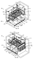
- FIG. 29 is an upper front right perspective view of an entire stormwater pollution prevention system 50 with cartridge system 1 with media cartridges 20 and cartridge tracks 26 of FIG. 11 with a hydro-slide system 200 .
- FIG. 30 is an upper rear left perspective view of the stormwater pollution prevention system 50 with hydro-slide system 200 of FIG. 29 .
- FIG. 31 is an upper rear right perspective view of the stormwater pollution prevention system 50 with hydro-slide system 200 of FIG. 29 .
- FIG. 32 is an upper front left perspective view of the stormwater pollution prevention system 50 with hydro-slide system 100 of FIG. 29 .
- FIG. 33 is an upper front right perspective view of the stormwater pollution prevention system 50 with using the polymer system 30 with polymer cartridges 40 and cartridge track 46 of FIG. 15 with a hydro-slide system 200 .
- FIG. 34 is an upper rear left perspective view of the stormwater pollution prevention system 50 with hydro-slide system 200 of FIG. 33 .
- FIG. 35 is an upper front left perspective view of the stormwater pollution prevention system 50 with hydro-slide system 200 of FIG. 33 .
- the hydroslide system 200 can include a water connection from outside of the vault/box 2 that feeds pressurized water through water line(s) 220 to spray bars 230 along the corner of where the side walls meet the side edges of the sloped floor 260 and with spray levers 240 and spray knifes 250 .
- the components in the hydroslide system 200 are described and shown in U.S. patent application Ser. No. 15/658,864 filed Jul. 25, 2017 to Happel; U.S. patent application Ser. No. 15/686,931 filed Aug. 25, 2017 to Happel; U.S. patent application Ser. No. 15/639,685 filed Jun. 30, 2017, to Happel, which are all incorporated by reference in their entireties.
- one of the primary objectives of the HydroSlide serving system 200 is to liquefy the sediment from underneath and thrust the debris toward the location in the settling chamber where it can be vacuumed out by a vacuum truck. This is accomplished by using water pumped into the servicing system 200 at high pressure from equipment located outside the vault 2 .
- the aiming levers 240 are parallel with the nozzles along the spray bars 230 .
- the technician installing the spray bars 230 simply needs to make sure the aiming lever 240 is pressed flat onto the floor 260 . This can be accomplished by pushing down on the aiming lever 240 until it hits onto the floor 260 . Regardless of the angle of the floor 260 , when the aiming lever 240 is pressed down onto the floor the nozzles will be parallel with the floor 260 . Because the process is so simple and quick, installation time and the required skill to install is minimized.
- the floors 260 of the stormwater treatment system will be sloped downward and away from the wall or walls of the vault 2 . Sloping the floors 260 will enable gravity to influence the movement of water and solids toward the center of the settling zone where a vacuum will remove the solids from the vault 2 . Both gravity and the kinetic energy of the water nozzles will direct solids toward the center of the settling zone.
- the media cartridges of the invention are sized and positioned so that they are below the static water line. Because the media and/or polymers will be continuously submerged they will perform optimally throughout the duration of their lifecycle.
- the filter cartridge will have the same type of force vectors acting on the horizontal surfaces of the cartridge.
- the invention can be used with one elongated float generally between the opposing sides of the vault/box.
Landscapes
- Chemical & Material Sciences (AREA)
- Life Sciences & Earth Sciences (AREA)
- Engineering & Computer Science (AREA)
- Hydrology & Water Resources (AREA)
- Water Supply & Treatment (AREA)
- Health & Medical Sciences (AREA)
- Public Health (AREA)
- Chemical Kinetics & Catalysis (AREA)
- Environmental & Geological Engineering (AREA)
- Organic Chemistry (AREA)
- Analytical Chemistry (AREA)
- Water Treatment By Sorption (AREA)
Abstract
Description
- 1 media cartridge vault/box system
- 2 vault/box
- 3 access point
- 4 baffle (wall)
- 5 skimmer tracks
- 6 floating skimmer
- 20 media cartridge(s)
- 22 cartridge handles
- 23 media
- 24 cartridge locks
- 25 screen(s)
- 25D screen door(s)
- 25B screen backing(s)
- 26 cartridge track/frame system
- 30 polymer cartridge vault/box system
- 40 polymer cartridge(s)
- 42 cartridge handles
- 43 polymer log(s)/polymer material
- 44 cartridge locks
- 45 screen(s)
- 45D screen door(s)
- 45B screen backing(s)
- 46 cartridge track/frame system
- 50 entire stormwater system
- 60 screen system
- 65 screen legs
- 70 deflector(s)
- 100 elongated servicing tool
- 105 hook end of tool
- 200 hydro-slide system/spray system
- 210 water connection/attachment fitting
- 220 water line
- 230 spray bars along corner of floor
- 240 spray lever
- 250 spray knife
- 260 sloped floors
Media Cartridge System
2) The hydro-variant skimmer portion of the invention is especially unique because the buoyancy of the skimmer is dependent only on the HGL along the upstream side of the skimmer. The space between the floats along the upstream side of the skimmer and the upstream side of the skimmer panel enable the water to encapsulate the floats for maximum buoyancy. If these floats were not separated from the skimmer panel the skimmer would not have front side buoyancy, and dependent on a HGL on both sides of the skimmer to float.
3) The invention is such that the arrangement of the cartridges along the back side of the fixed baffle is such that the cartridges do not interfere with the hydro-variant skimmer, and the cartridges can be easily reached by a service technician from outside the vault. The floats across the top of the hydro-variant skimmer would block easy access to the cartridges if the cartridges were placed along the front side of the baffle. If the cartridges were placed within the baffle then the body (skimmer panel) of the hydrovariant skimmer would block access to the cartridges.
4) The ability of the invention to use many different types of filtration media to target a wide variety of pollutants of concern. Generally, there is not a single type of filtration media that is the best at treating all types of pollutants. Having a treatment system that can accommodate many different types of filtration media is advantageous.
5) The ability of the invention to position the filtration media below the flow line between the inflow and outflow openings of the vault. This enables the filtration media to be continuously maintained in a wet condition which enhances the effectiveness of the media. In addition, water flow that passes through the vault is channeled so that it must pass through the filtration media, all the media is engaged with providing treatment to the water flow.
6) The ability of the invention to be able to accommodate polymers to treat stormwater flow. Polymers can be adapted to the cartridges to provide chemical treatment to stormwater flow. The cartridges can be filled with polymers.
7) The invention has the ability to maintain continuously submerged polymers. Polymers will dry out over time and become less effective when exposed to the air. Because the cartridges maintain polymers continuously submerged, the polymers will never dry out, and they will perform optimally until fully dissolved. In addition, water flow that passes through the vault is channeled so that it must pass through the cartridges, and all the polymer is engaged with providing treatment to the water flow.
8) The invention has the ability to apply media filtration and polymer dosing while fitting into a space that is less than the of other treatment systems.
9) The ability of the invention to store large volumes of sediment, and then have the sediment easily and quickly removed by a specialized sediment servicing system.
10) The ability of the invention to have debris removed from lower settling chambers quickly and easily without a service technician having to enter the vault. Because the service technician does not have to enter the vault, elaborate safety protocols do not have to be performed.
11) The ability of the invention to have debris removed from the lower settling chambers quickly and easily saves time and servicing costs. The sediment servicing system has the ability to remove the debris that settles in the lower settling chambers of the invention in a fraction of time. Faster servicing saves money by reducing labor and equipment costs.
Claims (20)
Priority Applications (1)
| Application Number | Priority Date | Filing Date | Title |
|---|---|---|---|
| US15/948,011 US10472815B1 (en) | 2013-05-30 | 2018-04-09 | Hydro-variant baffle cartridge system |
Applications Claiming Priority (7)
| Application Number | Priority Date | Filing Date | Title |
|---|---|---|---|
| US201361828958P | 2013-05-30 | 2013-05-30 | |
| US14/288,455 US20140352729A1 (en) | 2013-05-30 | 2014-05-28 | Stormwater vault apparatus and servicing process |
| US201762506188P | 2017-05-15 | 2017-05-15 | |
| US15/639,685 US10202285B1 (en) | 2013-05-30 | 2017-06-30 | Dual screen treatment system |
| US15/658,864 US10384956B1 (en) | 2013-05-30 | 2017-07-25 | Restrictive up flow media filter with servicing system |
| US15/686,931 US10155670B1 (en) | 2013-05-30 | 2017-08-25 | Stormwater polymer treatment system |
| US15/948,011 US10472815B1 (en) | 2013-05-30 | 2018-04-09 | Hydro-variant baffle cartridge system |
Related Parent Applications (1)
| Application Number | Title | Priority Date | Filing Date |
|---|---|---|---|
| US15/686,931 Continuation-In-Part US10155670B1 (en) | 2013-05-30 | 2017-08-25 | Stormwater polymer treatment system |
Publications (1)
| Publication Number | Publication Date |
|---|---|
| US10472815B1 true US10472815B1 (en) | 2019-11-12 |
Family
ID=68466405
Family Applications (1)
| Application Number | Title | Priority Date | Filing Date |
|---|---|---|---|
| US15/948,011 Expired - Fee Related US10472815B1 (en) | 2013-05-30 | 2018-04-09 | Hydro-variant baffle cartridge system |
Country Status (1)
| Country | Link |
|---|---|
| US (1) | US10472815B1 (en) |
Cited By (3)
| Publication number | Priority date | Publication date | Assignee | Title |
|---|---|---|---|---|
| US10907338B1 (en) * | 2013-05-30 | 2021-02-02 | Oldcastle Infrastructure, Inc. | Hinged variable flow skimmer and shelf system |
| US11155988B1 (en) | 2019-07-15 | 2021-10-26 | Summit Precast Concrete Lp | Systems and methods for stormwater detention |
| US11253798B2 (en) | 2013-05-30 | 2022-02-22 | Oldcastle Infrastructure, Inc. | Nutrient removal filtration system and method |
Citations (177)
| Publication number | Priority date | Publication date | Assignee | Title |
|---|---|---|---|---|
| US122209A (en) | 1871-12-26 | Improvement in sewer-traps and catch-basins | ||
| US232948A (en) | 1880-07-23 | 1880-10-05 | Sewer | |
| US587559A (en) | 1897-08-03 | James riley | ||
| US664945A (en) | 1899-10-20 | 1901-01-01 | Barnard R Guion | Sink. |
| US783556A (en) | 1904-07-29 | 1905-02-28 | Robert M Van Buskirk | Catch-basin top. |
| US809201A (en) | 1905-08-26 | 1906-01-02 | Us Sanitary And Utility Sewage Disposal Company | Receiving-basin. |
| US920961A (en) | 1908-09-11 | 1909-05-11 | Francis Keil & Son | Latch. |
| US1060338A (en) | 1912-05-11 | 1913-04-29 | William W Watson | Catch-basin. |
| US2102310A (en) | 1934-04-04 | 1937-12-14 | George F Egan | Construction of sewers and sewer basins and receptacles for use in sewer basins |
| US2182795A (en) | 1937-08-07 | 1939-12-12 | Louis J Day | Surface drain |
| US2263259A (en) | 1941-06-26 | 1941-11-18 | Edward W N Boosey | Self-cleaning drain head |
| US2360961A (en) | 1942-10-14 | 1944-10-24 | Morgan Smith S Co | Sluice gate |
| US2436793A (en) | 1944-07-01 | 1948-03-02 | Neyret Beylier & Piccard Picte | Sea wave power installation |
| US2485755A (en) | 1948-12-03 | 1949-10-25 | Loosli Dimond Herschel | Ditch dam |
| US2559784A (en) | 1945-05-07 | 1951-07-10 | Moore Richard Pierpont | Back washing filter |
| US2615526A (en) | 1950-12-21 | 1952-10-28 | Lane Frank | Sewer catch basin unit |
| US2652946A (en) | 1950-03-20 | 1953-09-22 | Guy M Beatty | Cleanout gate valve |
| US2796988A (en) | 1954-04-30 | 1957-06-25 | Loffler Walther | Valved catch basin |
| US3091339A (en) | 1959-10-19 | 1963-05-28 | Maria V Marra | Food cleaner type strainer pan |
| US3237915A (en) | 1963-07-18 | 1966-03-01 | Palmer Filter Equipment Compan | Sluice gate |
| US3282430A (en) | 1963-08-16 | 1966-11-01 | Felix L Kinne | Irrigation channel weed seed screen |
| US3527348A (en) | 1968-11-21 | 1970-09-08 | Henri Joseph Lalonde | Method and apparatus for separating immiscible liquids |
| US3631983A (en) | 1970-05-25 | 1972-01-04 | Combustion Eng | Method for backwashing filters |
| US4070863A (en) | 1976-11-05 | 1978-01-31 | Rodney Hunt Company | Sluice gate assembly with extrudable seal |
| US4189386A (en) | 1978-10-03 | 1980-02-19 | Aman Arcadio J | Debris separation and disposal system |
| US4198717A (en) | 1975-05-21 | 1980-04-22 | Bernhard Kessel | Modular assembly for drain trap |
| US4278190A (en) | 1980-01-07 | 1981-07-14 | Rotec Industries, Inc. | Concrete discharge hopper |
| US4297219A (en) | 1980-01-28 | 1981-10-27 | The Kbi Corp. | Temporary stream filtration system |
| US4308141A (en) | 1980-08-18 | 1981-12-29 | Clendenen Frank B | Modular filter system |
| US4326952A (en) | 1980-06-30 | 1982-04-27 | Blake Gene J | Precious metal recovery apparatus |
| US4422931A (en) | 1982-04-15 | 1983-12-27 | Wolde Michael Girma | Oil concentrator |
| US4509717A (en) | 1983-03-14 | 1985-04-09 | Elkem Metals Company | Slide gate valve for dry bulk discharging containers |
| US4668405A (en) | 1985-06-19 | 1987-05-26 | Process Development, Inc. | Downflow filter with high velocity backflush |
| US4689145A (en) | 1986-08-01 | 1987-08-25 | Mathews Lester R | Dry well filtration system |
| US4738644A (en) | 1987-02-27 | 1988-04-19 | Thomas Happel | Outboard motor attachment and method |
| US4765889A (en) | 1987-04-06 | 1988-08-23 | Lakeside Equipment Corporation | Moving bridge filter - telescoping floating pot skimmer |
| US4785966A (en) | 1987-11-05 | 1988-11-22 | Hoover Group, Inc. | Slide gate assembly |
| US4895653A (en) | 1988-01-29 | 1990-01-23 | Komline-Sanderson Engineering Corporation | Flooded bottom distribution system |
| US5034122A (en) | 1990-07-20 | 1991-07-23 | Wiesemann Enterprises, Inc. | Self cleaning static bar grid |
| US5037541A (en) | 1990-05-30 | 1991-08-06 | Ruey Jang Shiau | Sanitary device for sewerage channel |
| US5069781A (en) | 1990-05-10 | 1991-12-03 | Wilkes Gene W | Combined floor sink and strainer |
| US5133619A (en) | 1991-03-18 | 1992-07-28 | Murfae George W | Storm water filtration system for use with conventional storm water collection sewers |
| US5232587A (en) | 1992-03-02 | 1993-08-03 | Tom Hegemier | Stormwater inlet filter |
| US5284580A (en) | 1992-08-04 | 1994-02-08 | Shyh Shyh Yuan | Refuse collecting frame for sewer |
| US5372714A (en) | 1993-10-21 | 1994-12-13 | Logue, Jr.; George E. | Storm sewer catch basin and filter |
| US5378376A (en) | 1993-07-06 | 1995-01-03 | Wisconsin Oven Corporation | Sludge collector employing floating weir |
| US5397464A (en) | 1993-05-17 | 1995-03-14 | Hannon; Stephen R. | Trough type strainer box |
| US5403474A (en) | 1994-02-24 | 1995-04-04 | Emery; Grant R. | Curb inlet gravel sediment filter |
| US5405539A (en) | 1993-03-04 | 1995-04-11 | Schneider; Thomas W. | Storm drain filter system |
| US5480254A (en) | 1993-11-19 | 1996-01-02 | Autry; James L. | Storm drain box filter and method of use |
| US5486287A (en) | 1994-09-26 | 1996-01-23 | Murphy Marketing, Inc. | Wastewater straining device |
| US5518024A (en) | 1995-06-07 | 1996-05-21 | Emco Wheaton, Inc. | Overfill prevention device for storage tanks |
| US5535554A (en) | 1995-09-08 | 1996-07-16 | Harris Jr.; Walter E | Gutter and drain spout guard |
| US5562819A (en) | 1994-04-19 | 1996-10-08 | Fresh Creek Technologies, Inc. | Apparatus for trapping, signalling presence of and collecting debris in waterways |
| US5632889A (en) | 1995-06-09 | 1997-05-27 | Tharp; Gary D. | Filter cartridge for separating liquid hydrocarbons from water |
| US5643445A (en) | 1995-08-28 | 1997-07-01 | Billias; Charles | Removable storm water screen and overflow device |
| US5670039A (en) | 1995-05-26 | 1997-09-23 | Harris; Ronald B. | Linear solids removal unit |
| US5779888A (en) | 1995-09-04 | 1998-07-14 | Baramy Engineering Pty. Ltd. | Filtering apparatus |
| US5810510A (en) | 1993-12-14 | 1998-09-22 | Urriola; Humberto | Underground drainage system |
| US5820762A (en) | 1995-06-20 | 1998-10-13 | Bamer; Jonathan Michael | Filter insert for a storm drain |
| US5855774A (en) | 1997-03-28 | 1999-01-05 | Boelter; Carl | Storm drain filter |
| US5904842A (en) | 1995-08-28 | 1999-05-18 | Billias; Charles | Removable storm water devices |
| US5980740A (en) | 1998-01-06 | 1999-11-09 | Civitas Erosion Services, Inc. | Storm drain collection box filtration system |
| US5985157A (en) | 1996-08-01 | 1999-11-16 | Leckner; Justin Paul | Filter device |
| US6032421A (en) | 1996-11-28 | 2000-03-07 | Yamada; Susumu | Structural blocks for building a basement, block manufacturing method, block transporting method, and block installing method |
| US6077448A (en) | 1996-10-07 | 2000-06-20 | Wilkinson Heavy Precast | Oil/grit interceptor |
| US6086758A (en) | 1998-11-13 | 2000-07-11 | Pactec, Inc. | Storm drain liner |
| US6086756A (en) | 1996-10-23 | 2000-07-11 | Ecosol Pty Ltd | Gross pollution filter |
| US6099743A (en) | 1995-02-17 | 2000-08-08 | Odense Vandselskab A/S | Method and basin for sedimentation of sludge in waste water |
| US6106706A (en) | 1995-10-30 | 2000-08-22 | Rsf Patent Pty Ltd. | Storm water filter arrangement |
| US6106707A (en) | 1998-02-18 | 2000-08-22 | Abtech Industries, Inc. | Curb-inlet storm drain systems for filtering trash and hydrocarbons |
| US6149803A (en) | 1998-08-28 | 2000-11-21 | Atlantic Contruction Fabrics, Inc. | Storm sewer catch basin filter |
| US6178565B1 (en) | 2000-01-07 | 2001-01-30 | Jose Franco | Trash collector for exfiltration drain system |
| US6190545B1 (en) | 1998-04-01 | 2001-02-20 | Remedial Solutions, Inc. | Drainwater treatment system for use in a horizontal passageway |
| US6200484B1 (en) | 2000-03-16 | 2001-03-13 | Mcinnis Stephen J. | Surface water filtration apparatus |
| US6270663B1 (en) | 2000-07-17 | 2001-08-07 | Henry Happel | Storm drain filter system |
| US6287459B1 (en) | 1998-04-01 | 2001-09-11 | Remedial Solutions, Inc. | Drainwater treatment system for use in a vertical passageway |
| US6294095B1 (en) | 2000-04-24 | 2001-09-25 | Erosion Control Services, Inc. | Silt filtration system |
| US20010047954A1 (en) | 2000-05-30 | 2001-12-06 | Henry Happel | In-line storm water drain filter system |
| US6334953B1 (en) | 1999-11-24 | 2002-01-01 | Roger Singleton | Storm water drainage filter assembly |
| US6379541B1 (en) | 1996-02-21 | 2002-04-30 | Douglas Ian Nicholas | Stormwater sediment and litter trap |
| US6478954B1 (en) | 2001-06-06 | 2002-11-12 | Fresh Creek Technologies, Inc. | Debris collecting apparatus |
| US20030026659A1 (en) | 2001-08-01 | 2003-02-06 | Chun-Ching Wu | Water gate opened and closed by oil pressure |
| US6517709B1 (en) | 2000-01-14 | 2003-02-11 | Troy Cardwell | Catch basin erosion containment filter assembly |
| US6531059B1 (en) | 2000-10-05 | 2003-03-11 | Abtech Industries, Inc. | Suspended runoff water filter |
| US6537446B1 (en) | 2001-03-16 | 2003-03-25 | The Water Sweeper | Drainage filter system for debris and contaminant removal |
| US6551023B2 (en) | 1999-08-27 | 2003-04-22 | Kristar Enterprises, Inc. | Soft bodied high capacity catch basin filtration system |
| US6562233B1 (en) | 1998-11-13 | 2003-05-13 | Pactec, Inc. | Storm drain line with riser 2 |
| US20030121846A1 (en) | 2001-12-31 | 2003-07-03 | Use Clark Joseph | Multi-stage water pollution trap |
| US20030132150A1 (en) | 2002-01-15 | 2003-07-17 | Henry Happel | Catch basin filter for stormwater runoff |
| US20030136717A1 (en) | 2002-01-24 | 2003-07-24 | Tseng Wen Ching | Drain garbage collector |
| US20030175079A1 (en) | 2002-03-12 | 2003-09-18 | Henry Happel | Golf course green storm water filter |
| US20030172487A1 (en) | 2002-03-15 | 2003-09-18 | Thompson Ronald L. | Sewer cleaning tool |
| US6638424B2 (en) | 2000-01-19 | 2003-10-28 | Jensen Enterprises | Stormwater treatment apparatus |
| US6651825B2 (en) | 2001-06-06 | 2003-11-25 | Fresh Creek Technologies, Inc. | Disposable net assemblies for apparatus for collecting floating debris |
| US6666974B2 (en) | 2001-11-20 | 2003-12-23 | Ardle E. Page | Subgrate drain basin filter |
| US6668390B1 (en) | 2002-05-20 | 2003-12-30 | Raul Gonzalez | Debris recovery for drainage system |
| US20040065601A1 (en) | 2002-10-08 | 2004-04-08 | Antonio Martinez | Curbside trap for pollutants and solid trash |
| US6733665B1 (en) | 2001-02-22 | 2004-05-11 | Saleh S. Khalil | Storm drain system for preventing and filtering debris, trash and hydrocarbons with removable inserts |
| US6767456B2 (en) * | 2001-03-19 | 2004-07-27 | Circle Environmental, Inc. | Reusable storm water sampler and pollutant filter insert |
| US6800195B1 (en) | 2002-06-04 | 2004-10-05 | Thermaco, Inc. | Low cost grease removal system |
| US20040222159A1 (en) | 2003-05-05 | 2004-11-11 | John Peters | System and process for removing contaminants from storm water |
| US20040226869A1 (en) | 2003-05-12 | 2004-11-18 | Mcclure Stewart D. | Stormdrain curb-inlet multi-stage filtration-unit |
| JP2004353407A (en) | 2003-05-30 | 2004-12-16 | Sumikin Recotech Co Ltd | Water level regulation sluice |
| US20050051499A1 (en) | 2003-09-04 | 2005-03-10 | Nino Khalil Ibrahim | Large area catch basin filter |
| US6869525B1 (en) | 2002-01-24 | 2005-03-22 | Henry Happel | Storm drain filter system |
| US6872029B2 (en) | 1999-08-27 | 2005-03-29 | Kristar Enterprises, Inc. | Hard bodied high capacity catch basin filtration system |
| US20050069386A1 (en) | 2003-03-11 | 2005-03-31 | Henry Happel | Golf course green storm water filter |
| US6884343B2 (en) | 2001-09-07 | 2005-04-26 | John F. Harris | Curb inlet catch basin filter |
| US20050183997A1 (en) | 2004-02-24 | 2005-08-25 | Henry Happel | Street curb filter basket system |
| US6936163B2 (en) | 2001-12-31 | 2005-08-30 | Clark Joseph Use | Water pollution trap with clay collector |
| US6939461B2 (en) | 2001-12-31 | 2005-09-06 | Clark Joseph Use | Water pollution trap with oil segregator/collector |
| US6951607B2 (en) | 2001-12-31 | 2005-10-04 | Clark Joseph Use | Mobile pollution trap and method |
| US20050218049A1 (en) | 2004-04-05 | 2005-10-06 | Henry Happel | Floating storm water drain basket |
| US6974540B1 (en) | 2004-10-27 | 2005-12-13 | Fleischmann Charles R | Street curb drain filter |
| US6976808B2 (en) | 1999-08-27 | 2005-12-20 | Kristar Enterprises, Inc. | Catch basin filtration system will disposable silt/contaminant collector |
| US6986621B2 (en) | 1999-08-27 | 2006-01-17 | Kristar Enterprises, Inc. | Trench drain filtration system |
| US20060016767A1 (en) | 2004-07-23 | 2006-01-26 | I.S.C. Environmental, Inc. | Fluid filter system and related method |
| US6994783B2 (en) | 2001-12-31 | 2006-02-07 | Clark Joseph Use | Water pollution trap with inlet basket |
| US6998039B2 (en) | 2001-01-25 | 2006-02-14 | Harris John F | Catch basin filter |
| US7005060B2 (en) | 2003-06-10 | 2006-02-28 | Stormtrain Llc | Upflow surface water runoff filtration system |
| US7011743B2 (en) | 2001-12-31 | 2006-03-14 | Clark Joseph Use | Water pollution trap with water flow baffles |
| US20060096935A1 (en) | 2004-11-08 | 2006-05-11 | Harding Darin M | Method and apparatus for removing cuttings from drilling fluids |
| US20060163130A1 (en) | 2005-01-24 | 2006-07-27 | Henry Happel | Storm water filter system |
| US7094337B2 (en) | 2001-10-10 | 2006-08-22 | Hydro International Plc | Overflow chamber |
| US20060201860A1 (en) | 2005-03-11 | 2006-09-14 | Henry Happel | Storm water drain system |
| US20060207922A1 (en) | 2005-03-21 | 2006-09-21 | Dussich George V A I | Storm water filtration system |
| US7112274B1 (en) | 2003-09-30 | 2006-09-26 | Sanguinetti Peter S | Post-production drain inlet filter system |
| US7128341B1 (en) | 2003-02-28 | 2006-10-31 | Polaris Industries Inc. | All-terrain vehicle storage box |
| US7128832B2 (en) | 2003-10-21 | 2006-10-31 | Rodney George Wade | Filter pit |
| US7132045B1 (en) | 2004-10-07 | 2006-11-07 | Trangsrud & Associates, Inc. | Sanitary, storm and catch basin trap with filter insert |
| US7156987B1 (en) | 2004-02-03 | 2007-01-02 | Sanguinetti Peter S | Storm drain filter device |
| US7282142B2 (en) | 2002-04-22 | 2007-10-16 | Kraft Wayne J | Fluid strainer assembly |
| US7288188B2 (en) | 2006-02-27 | 2007-10-30 | Faisal Abdul Aziz Al-Assfour | Ground water collection system |
| US7328809B2 (en) | 2003-08-21 | 2008-02-12 | Spx Corporation | Solvent extraction method and apparatus |
| US7396471B2 (en) | 2001-01-08 | 2008-07-08 | Wimberger Brian J | Sediment control drain and method of construction |
| FR2916458A1 (en) * | 2007-05-25 | 2008-11-28 | Constru Sa | Manhole for filtering rain water, has pipe with mouthpiece having filter holder for receiving filter, where holder or filter presents latch for assuring locking in translation of external frame with respect to internal frame |
| US20090045135A1 (en) | 2007-08-18 | 2009-02-19 | Khudenko Engineering, Inc. | Method for water filtration |
| US7524414B1 (en) | 2007-05-22 | 2009-04-28 | Candelario Barragan | Apparatus for filtering out and collecting debris at a storm drain |
| US20090114579A1 (en) | 2005-07-05 | 2009-05-07 | John Raymond Dyer | Trash Screen For Side Entry Pit |
| US20090134081A1 (en) | 2007-11-19 | 2009-05-28 | Henry Happel | Adjustable filter basket for a storm water drain system |
| US20090166279A1 (en) | 2007-12-27 | 2009-07-02 | Henry Happel | Storm water filter system having a floating skimmer apparatus |
| US7658857B2 (en) | 2008-01-08 | 2010-02-09 | Todd Wacome | Treating runoff |
| US20100032363A1 (en) | 2007-12-27 | 2010-02-11 | Happel Thomas H | Floating skimmer apparatus with up-flow filter |
| US7662280B1 (en) | 2006-08-28 | 2010-02-16 | Cooney John R | Catch basin sealing system |
| US20100078370A1 (en) | 2007-12-27 | 2010-04-01 | Happel Thomas H | Floating baffle panel and filter apparatus |
| US7722763B2 (en) * | 2007-04-24 | 2010-05-25 | Jeffrey Benty | Purification and separation system for a fluid flow stream |
| US7771591B2 (en) | 2007-10-23 | 2010-08-10 | Chassidy Lucas | Filter system for catch basins |
| US7785464B2 (en) | 2007-12-06 | 2010-08-31 | Happel Thomas H | Flocculate dosing tray |
| US7815800B2 (en) | 2003-11-20 | 2010-10-19 | Kiyoshi Komatsu | Refuse/oil removing device and refuse/oil recovery bag |
| US7824551B2 (en) | 2007-08-31 | 2010-11-02 | University Of Central Florida Research Foundation, Inc. | Passive nutrient removal material mixes |
| US7883620B2 (en) | 2006-11-07 | 2011-02-08 | Jonathan Owen | Filter trap for waste water |
| US7927484B2 (en) | 2008-09-11 | 2011-04-19 | University Of Central Florida Research Foundation, Inc. | Passive underground drainfield for septic tank nutrient removal using functionalized green filtration media |
| US20110168612A1 (en) | 2007-12-27 | 2011-07-14 | Happel Thomas H | Storm water filter basket with floating bypass panels |
| US8002984B1 (en) | 2007-08-31 | 2011-08-23 | University Of Central Florida Research Foundation, Inc. | Green sorption material mixes for water treatment |
| US8017006B2 (en) | 2009-04-10 | 2011-09-13 | Eudoro Lopez | Storm water filtration apparatus |
| US8034237B2 (en) | 2007-12-17 | 2011-10-11 | Dolores J. Happel, legal representative | Backwashing filter basket |
| US8034236B1 (en) | 2007-12-27 | 2011-10-11 | Happel Thomas H | Storm water filter system having a floating skimmer apparatus |
| US8051568B2 (en) | 2006-06-13 | 2011-11-08 | Moody Gary L | Grate cover apparatus and method |
| US20110278237A1 (en) | 2010-05-12 | 2011-11-17 | Catch-All, Llc | Deformable sump insert |
| US8142666B1 (en) | 2008-12-02 | 2012-03-27 | Tom Happel | Baffle box deflectors and flow spreaders |
| US8221632B2 (en) | 2009-12-30 | 2012-07-17 | Cleanway Environmental Partners, Inc. | Surface water filtration device |
| US8231780B2 (en) | 2007-12-27 | 2012-07-31 | Happel Thomas H | Floating skimmer and filter apparatus |
| US8252182B1 (en) | 2008-09-11 | 2012-08-28 | University Of Central Florida Research Foundation, Inc. | Subsurface upflow wetland system for nutrient and pathogen removal in wastewater treatment systems |
| US8366923B1 (en) | 2007-11-19 | 2013-02-05 | Tom Happel | Telescoping post supports and sliding lid systems for filter baskets |
| US8393827B1 (en) | 2009-07-31 | 2013-03-12 | Tom Happel | Box service panel door and equalizer |
| US8425150B1 (en) | 2009-07-31 | 2013-04-23 | Tom Happel | Rotatable wheel box service panel door and equalizer |
| US8491797B1 (en) | 2010-07-16 | 2013-07-23 | Tom Happel | Pivoting panel, pylon and inflow gap for stormwater screen system |
| US8622652B1 (en) | 2009-07-31 | 2014-01-07 | Tom Happel | Overflow and underflow doors |
| US8658044B2 (en) | 2009-09-09 | 2014-02-25 | Contech Engineered Solutions LLC | Stormwater filtration apparatus, system and method |
| US20140352729A1 (en) | 2013-05-30 | 2014-12-04 | Thomas H. Happel | Stormwater vault apparatus and servicing process |
| US20150129473A1 (en) | 2013-11-11 | 2015-05-14 | Zaccharia Kent | Partitioned Separator Water Treatment System with Upflow Filter |
| US9340965B2 (en) | 2012-12-10 | 2016-05-17 | Thomas H Happel | Storm water vault having an articulated floating screen filter system |
| US9534368B1 (en) | 2014-12-18 | 2017-01-03 | Tom Happel | Variable flow skimmer and shelf system |
| US10155670B1 (en) * | 2013-05-30 | 2018-12-18 | Suntree Technologies Holdings, Llc | Stormwater polymer treatment system |
| US10238993B1 (en) * | 2013-05-30 | 2019-03-26 | Suntree Technologies Holdings, Llc | Dual screen treatment systems with debris ramps and screened deflectors |
| US10287768B1 (en) * | 2013-05-30 | 2019-05-14 | Suntree Technologies Holdings LLC | Stormwater vault apparatus and method |
-
2018
- 2018-04-09 US US15/948,011 patent/US10472815B1/en not_active Expired - Fee Related
Patent Citations (210)
| Publication number | Priority date | Publication date | Assignee | Title |
|---|---|---|---|---|
| US122209A (en) | 1871-12-26 | Improvement in sewer-traps and catch-basins | ||
| US587559A (en) | 1897-08-03 | James riley | ||
| US232948A (en) | 1880-07-23 | 1880-10-05 | Sewer | |
| US664945A (en) | 1899-10-20 | 1901-01-01 | Barnard R Guion | Sink. |
| US783556A (en) | 1904-07-29 | 1905-02-28 | Robert M Van Buskirk | Catch-basin top. |
| US809201A (en) | 1905-08-26 | 1906-01-02 | Us Sanitary And Utility Sewage Disposal Company | Receiving-basin. |
| US920961A (en) | 1908-09-11 | 1909-05-11 | Francis Keil & Son | Latch. |
| US1060338A (en) | 1912-05-11 | 1913-04-29 | William W Watson | Catch-basin. |
| US2102310A (en) | 1934-04-04 | 1937-12-14 | George F Egan | Construction of sewers and sewer basins and receptacles for use in sewer basins |
| US2182795A (en) | 1937-08-07 | 1939-12-12 | Louis J Day | Surface drain |
| US2263259A (en) | 1941-06-26 | 1941-11-18 | Edward W N Boosey | Self-cleaning drain head |
| US2360961A (en) | 1942-10-14 | 1944-10-24 | Morgan Smith S Co | Sluice gate |
| US2436793A (en) | 1944-07-01 | 1948-03-02 | Neyret Beylier & Piccard Picte | Sea wave power installation |
| US2559784A (en) | 1945-05-07 | 1951-07-10 | Moore Richard Pierpont | Back washing filter |
| US2485755A (en) | 1948-12-03 | 1949-10-25 | Loosli Dimond Herschel | Ditch dam |
| US2652946A (en) | 1950-03-20 | 1953-09-22 | Guy M Beatty | Cleanout gate valve |
| US2615526A (en) | 1950-12-21 | 1952-10-28 | Lane Frank | Sewer catch basin unit |
| US2796988A (en) | 1954-04-30 | 1957-06-25 | Loffler Walther | Valved catch basin |
| US3091339A (en) | 1959-10-19 | 1963-05-28 | Maria V Marra | Food cleaner type strainer pan |
| US3237915A (en) | 1963-07-18 | 1966-03-01 | Palmer Filter Equipment Compan | Sluice gate |
| US3282430A (en) | 1963-08-16 | 1966-11-01 | Felix L Kinne | Irrigation channel weed seed screen |
| US3527348A (en) | 1968-11-21 | 1970-09-08 | Henri Joseph Lalonde | Method and apparatus for separating immiscible liquids |
| US3631983A (en) | 1970-05-25 | 1972-01-04 | Combustion Eng | Method for backwashing filters |
| US4198717A (en) | 1975-05-21 | 1980-04-22 | Bernhard Kessel | Modular assembly for drain trap |
| US4070863A (en) | 1976-11-05 | 1978-01-31 | Rodney Hunt Company | Sluice gate assembly with extrudable seal |
| US4189386A (en) | 1978-10-03 | 1980-02-19 | Aman Arcadio J | Debris separation and disposal system |
| US4278190A (en) | 1980-01-07 | 1981-07-14 | Rotec Industries, Inc. | Concrete discharge hopper |
| US4297219A (en) | 1980-01-28 | 1981-10-27 | The Kbi Corp. | Temporary stream filtration system |
| US4326952A (en) | 1980-06-30 | 1982-04-27 | Blake Gene J | Precious metal recovery apparatus |
| US4308141A (en) | 1980-08-18 | 1981-12-29 | Clendenen Frank B | Modular filter system |
| US4422931A (en) | 1982-04-15 | 1983-12-27 | Wolde Michael Girma | Oil concentrator |
| US4509717A (en) | 1983-03-14 | 1985-04-09 | Elkem Metals Company | Slide gate valve for dry bulk discharging containers |
| US4668405A (en) | 1985-06-19 | 1987-05-26 | Process Development, Inc. | Downflow filter with high velocity backflush |
| US4689145A (en) | 1986-08-01 | 1987-08-25 | Mathews Lester R | Dry well filtration system |
| US4738644A (en) | 1987-02-27 | 1988-04-19 | Thomas Happel | Outboard motor attachment and method |
| US4765889A (en) | 1987-04-06 | 1988-08-23 | Lakeside Equipment Corporation | Moving bridge filter - telescoping floating pot skimmer |
| US4785966A (en) | 1987-11-05 | 1988-11-22 | Hoover Group, Inc. | Slide gate assembly |
| US4895653A (en) | 1988-01-29 | 1990-01-23 | Komline-Sanderson Engineering Corporation | Flooded bottom distribution system |
| US5069781A (en) | 1990-05-10 | 1991-12-03 | Wilkes Gene W | Combined floor sink and strainer |
| US5037541A (en) | 1990-05-30 | 1991-08-06 | Ruey Jang Shiau | Sanitary device for sewerage channel |
| US5034122A (en) | 1990-07-20 | 1991-07-23 | Wiesemann Enterprises, Inc. | Self cleaning static bar grid |
| US5133619A (en) | 1991-03-18 | 1992-07-28 | Murfae George W | Storm water filtration system for use with conventional storm water collection sewers |
| US5232587A (en) | 1992-03-02 | 1993-08-03 | Tom Hegemier | Stormwater inlet filter |
| US5284580A (en) | 1992-08-04 | 1994-02-08 | Shyh Shyh Yuan | Refuse collecting frame for sewer |
| US5405539A (en) | 1993-03-04 | 1995-04-11 | Schneider; Thomas W. | Storm drain filter system |
| US5397464A (en) | 1993-05-17 | 1995-03-14 | Hannon; Stephen R. | Trough type strainer box |
| US5378376A (en) | 1993-07-06 | 1995-01-03 | Wisconsin Oven Corporation | Sludge collector employing floating weir |
| US5372714A (en) | 1993-10-21 | 1994-12-13 | Logue, Jr.; George E. | Storm sewer catch basin and filter |
| US5575925A (en) | 1993-10-21 | 1996-11-19 | Logue, Jr.; George E. | Storm sewer catch basin and filter |
| US5575925C1 (en) | 1993-10-21 | 2001-03-06 | George E Logue Jr | Storm sewer catch basin and filter |
| US5480254A (en) | 1993-11-19 | 1996-01-02 | Autry; James L. | Storm drain box filter and method of use |
| US5810510A (en) | 1993-12-14 | 1998-09-22 | Urriola; Humberto | Underground drainage system |
| US5403474A (en) | 1994-02-24 | 1995-04-04 | Emery; Grant R. | Curb inlet gravel sediment filter |
| US5562819A (en) | 1994-04-19 | 1996-10-08 | Fresh Creek Technologies, Inc. | Apparatus for trapping, signalling presence of and collecting debris in waterways |
| US5486287A (en) | 1994-09-26 | 1996-01-23 | Murphy Marketing, Inc. | Wastewater straining device |
| US6099743A (en) | 1995-02-17 | 2000-08-08 | Odense Vandselskab A/S | Method and basin for sedimentation of sludge in waste water |
| US5670039A (en) | 1995-05-26 | 1997-09-23 | Harris; Ronald B. | Linear solids removal unit |
| US5518024A (en) | 1995-06-07 | 1996-05-21 | Emco Wheaton, Inc. | Overfill prevention device for storage tanks |
| US5632889A (en) | 1995-06-09 | 1997-05-27 | Tharp; Gary D. | Filter cartridge for separating liquid hydrocarbons from water |
| US5820762A (en) | 1995-06-20 | 1998-10-13 | Bamer; Jonathan Michael | Filter insert for a storm drain |
| US5643445A (en) | 1995-08-28 | 1997-07-01 | Billias; Charles | Removable storm water screen and overflow device |
| US5904842A (en) | 1995-08-28 | 1999-05-18 | Billias; Charles | Removable storm water devices |
| US5779888A (en) | 1995-09-04 | 1998-07-14 | Baramy Engineering Pty. Ltd. | Filtering apparatus |
| US5535554A (en) | 1995-09-08 | 1996-07-16 | Harris Jr.; Walter E | Gutter and drain spout guard |
| US6106706A (en) | 1995-10-30 | 2000-08-22 | Rsf Patent Pty Ltd. | Storm water filter arrangement |
| US6379541B1 (en) | 1996-02-21 | 2002-04-30 | Douglas Ian Nicholas | Stormwater sediment and litter trap |
| US5985157A (en) | 1996-08-01 | 1999-11-16 | Leckner; Justin Paul | Filter device |
| US6077448A (en) | 1996-10-07 | 2000-06-20 | Wilkinson Heavy Precast | Oil/grit interceptor |
| US6086756A (en) | 1996-10-23 | 2000-07-11 | Ecosol Pty Ltd | Gross pollution filter |
| US6032421A (en) | 1996-11-28 | 2000-03-07 | Yamada; Susumu | Structural blocks for building a basement, block manufacturing method, block transporting method, and block installing method |
| US5855774A (en) | 1997-03-28 | 1999-01-05 | Boelter; Carl | Storm drain filter |
| US5980740A (en) | 1998-01-06 | 1999-11-09 | Civitas Erosion Services, Inc. | Storm drain collection box filtration system |
| US6106707A (en) | 1998-02-18 | 2000-08-22 | Abtech Industries, Inc. | Curb-inlet storm drain systems for filtering trash and hydrocarbons |
| US6231758B1 (en) | 1998-02-18 | 2001-05-15 | Abtech Industries, Inc. | Curb-inlet storm drain systems for filtering trash and hydrocarbons |
| US6190545B1 (en) | 1998-04-01 | 2001-02-20 | Remedial Solutions, Inc. | Drainwater treatment system for use in a horizontal passageway |
| US6287459B1 (en) | 1998-04-01 | 2001-09-11 | Remedial Solutions, Inc. | Drainwater treatment system for use in a vertical passageway |
| US6149803A (en) | 1998-08-28 | 2000-11-21 | Atlantic Contruction Fabrics, Inc. | Storm sewer catch basin filter |
| US6562233B1 (en) | 1998-11-13 | 2003-05-13 | Pactec, Inc. | Storm drain line with riser 2 |
| US6086758A (en) | 1998-11-13 | 2000-07-11 | Pactec, Inc. | Storm drain liner |
| US6872029B2 (en) | 1999-08-27 | 2005-03-29 | Kristar Enterprises, Inc. | Hard bodied high capacity catch basin filtration system |
| US6976808B2 (en) | 1999-08-27 | 2005-12-20 | Kristar Enterprises, Inc. | Catch basin filtration system will disposable silt/contaminant collector |
| US6986621B2 (en) | 1999-08-27 | 2006-01-17 | Kristar Enterprises, Inc. | Trench drain filtration system |
| US6551023B2 (en) | 1999-08-27 | 2003-04-22 | Kristar Enterprises, Inc. | Soft bodied high capacity catch basin filtration system |
| US6334953B1 (en) | 1999-11-24 | 2002-01-01 | Roger Singleton | Storm water drainage filter assembly |
| US6178565B1 (en) | 2000-01-07 | 2001-01-30 | Jose Franco | Trash collector for exfiltration drain system |
| US6517709B1 (en) | 2000-01-14 | 2003-02-11 | Troy Cardwell | Catch basin erosion containment filter assembly |
| US6638424B2 (en) | 2000-01-19 | 2003-10-28 | Jensen Enterprises | Stormwater treatment apparatus |
| US6200484B1 (en) | 2000-03-16 | 2001-03-13 | Mcinnis Stephen J. | Surface water filtration apparatus |
| US6294095B1 (en) | 2000-04-24 | 2001-09-25 | Erosion Control Services, Inc. | Silt filtration system |
| US6428692B2 (en) | 2000-05-30 | 2002-08-06 | Henry Happel | In-line storm water drain filter system |
| US20010047954A1 (en) | 2000-05-30 | 2001-12-06 | Henry Happel | In-line storm water drain filter system |
| US6270663B1 (en) | 2000-07-17 | 2001-08-07 | Henry Happel | Storm drain filter system |
| US6531059B1 (en) | 2000-10-05 | 2003-03-11 | Abtech Industries, Inc. | Suspended runoff water filter |
| US7094338B2 (en) | 2000-10-05 | 2006-08-22 | Abtech Industries, Inc. | Method of making and using a filter in the form of a block of agglomerated copolymer fragments |
| US7488414B2 (en) | 2001-01-08 | 2009-02-10 | Wimberger Brian J | Storm water filter for positioning within a storm water inlet |
| US7396471B2 (en) | 2001-01-08 | 2008-07-08 | Wimberger Brian J | Sediment control drain and method of construction |
| US6998039B2 (en) | 2001-01-25 | 2006-02-14 | Harris John F | Catch basin filter |
| US6733665B1 (en) | 2001-02-22 | 2004-05-11 | Saleh S. Khalil | Storm drain system for preventing and filtering debris, trash and hydrocarbons with removable inserts |
| US6537446B1 (en) | 2001-03-16 | 2003-03-25 | The Water Sweeper | Drainage filter system for debris and contaminant removal |
| US6767456B2 (en) * | 2001-03-19 | 2004-07-27 | Circle Environmental, Inc. | Reusable storm water sampler and pollutant filter insert |
| US6866153B2 (en) | 2001-06-06 | 2005-03-15 | Fresh Creek Technologies, Inc. | Disposable net assemblies for apparatus for collecting floating debris |
| US6651825B2 (en) | 2001-06-06 | 2003-11-25 | Fresh Creek Technologies, Inc. | Disposable net assemblies for apparatus for collecting floating debris |
| US6478954B1 (en) | 2001-06-06 | 2002-11-12 | Fresh Creek Technologies, Inc. | Debris collecting apparatus |
| US20030026659A1 (en) | 2001-08-01 | 2003-02-06 | Chun-Ching Wu | Water gate opened and closed by oil pressure |
| US6884343B2 (en) | 2001-09-07 | 2005-04-26 | John F. Harris | Curb inlet catch basin filter |
| US7094337B2 (en) | 2001-10-10 | 2006-08-22 | Hydro International Plc | Overflow chamber |
| US6666974B2 (en) | 2001-11-20 | 2003-12-23 | Ardle E. Page | Subgrate drain basin filter |
| US6797161B2 (en) | 2001-12-31 | 2004-09-28 | Clark Joseph Use | Multi-stage water pollution trap |
| US6939461B2 (en) | 2001-12-31 | 2005-09-06 | Clark Joseph Use | Water pollution trap with oil segregator/collector |
| US20030121846A1 (en) | 2001-12-31 | 2003-07-03 | Use Clark Joseph | Multi-stage water pollution trap |
| US7011743B2 (en) | 2001-12-31 | 2006-03-14 | Clark Joseph Use | Water pollution trap with water flow baffles |
| US6994783B2 (en) | 2001-12-31 | 2006-02-07 | Clark Joseph Use | Water pollution trap with inlet basket |
| US6951607B2 (en) | 2001-12-31 | 2005-10-04 | Clark Joseph Use | Mobile pollution trap and method |
| US6936163B2 (en) | 2001-12-31 | 2005-08-30 | Clark Joseph Use | Water pollution trap with clay collector |
| US20030132150A1 (en) | 2002-01-15 | 2003-07-17 | Henry Happel | Catch basin filter for stormwater runoff |
| US6797162B2 (en) | 2002-01-15 | 2004-09-28 | Henry Happel | Catch basin filter for stormwater runoff |
| US20030136717A1 (en) | 2002-01-24 | 2003-07-24 | Tseng Wen Ching | Drain garbage collector |
| US6869525B1 (en) | 2002-01-24 | 2005-03-22 | Henry Happel | Storm drain filter system |
| US20030175079A1 (en) | 2002-03-12 | 2003-09-18 | Henry Happel | Golf course green storm water filter |
| US20030172487A1 (en) | 2002-03-15 | 2003-09-18 | Thompson Ronald L. | Sewer cleaning tool |
| US8038879B2 (en) | 2002-04-22 | 2011-10-18 | Wayne Kraft | Fluid strainer assembly |
| US7282142B2 (en) | 2002-04-22 | 2007-10-16 | Kraft Wayne J | Fluid strainer assembly |
| US6668390B1 (en) | 2002-05-20 | 2003-12-30 | Raul Gonzalez | Debris recovery for drainage system |
| US6800195B1 (en) | 2002-06-04 | 2004-10-05 | Thermaco, Inc. | Low cost grease removal system |
| US6824677B2 (en) | 2002-10-08 | 2004-11-30 | Antonio Martinez | Curbside trap for pollutants and solid trash |
| US20040065601A1 (en) | 2002-10-08 | 2004-04-08 | Antonio Martinez | Curbside trap for pollutants and solid trash |
| US7128341B1 (en) | 2003-02-28 | 2006-10-31 | Polaris Industries Inc. | All-terrain vehicle storage box |
| US6979148B2 (en) | 2003-03-11 | 2005-12-27 | Henry Happel | Golf course green storm water filter |
| US20050069386A1 (en) | 2003-03-11 | 2005-03-31 | Henry Happel | Golf course green storm water filter |
| US20040222159A1 (en) | 2003-05-05 | 2004-11-11 | John Peters | System and process for removing contaminants from storm water |
| US20040226869A1 (en) | 2003-05-12 | 2004-11-18 | Mcclure Stewart D. | Stormdrain curb-inlet multi-stage filtration-unit |
| US7083721B2 (en) | 2003-05-12 | 2006-08-01 | Mcclure Stewart D | Stormdrain curb-inlet multi-stage filtration-unit |
| JP2004353407A (en) | 2003-05-30 | 2004-12-16 | Sumikin Recotech Co Ltd | Water level regulation sluice |
| US7005060B2 (en) | 2003-06-10 | 2006-02-28 | Stormtrain Llc | Upflow surface water runoff filtration system |
| US7328809B2 (en) | 2003-08-21 | 2008-02-12 | Spx Corporation | Solvent extraction method and apparatus |
| US20050051499A1 (en) | 2003-09-04 | 2005-03-10 | Nino Khalil Ibrahim | Large area catch basin filter |
| US7494585B2 (en) | 2003-09-04 | 2009-02-24 | Khalil Ibrahim Nino | Large area catch basin filter |
| US7112274B1 (en) | 2003-09-30 | 2006-09-26 | Sanguinetti Peter S | Post-production drain inlet filter system |
| US7128832B2 (en) | 2003-10-21 | 2006-10-31 | Rodney George Wade | Filter pit |
| US7815800B2 (en) | 2003-11-20 | 2010-10-19 | Kiyoshi Komatsu | Refuse/oil removing device and refuse/oil recovery bag |
| US7156987B1 (en) | 2004-02-03 | 2007-01-02 | Sanguinetti Peter S | Storm drain filter device |
| US20050183997A1 (en) | 2004-02-24 | 2005-08-25 | Henry Happel | Street curb filter basket system |
| US7959799B2 (en) | 2004-02-24 | 2011-06-14 | Henry Happel | Street curb filter basket system |
| US7153417B2 (en) | 2004-04-05 | 2006-12-26 | Henry Happel | Floating storm water drain basket |
| US20050218049A1 (en) | 2004-04-05 | 2005-10-06 | Henry Happel | Floating storm water drain basket |
| US20060016767A1 (en) | 2004-07-23 | 2006-01-26 | I.S.C. Environmental, Inc. | Fluid filter system and related method |
| US7132045B1 (en) | 2004-10-07 | 2006-11-07 | Trangsrud & Associates, Inc. | Sanitary, storm and catch basin trap with filter insert |
| US7309420B1 (en) | 2004-10-07 | 2007-12-18 | Royal Concrete Pipe, Inc. | Sanitary, storm and catch basin trap with filter insert |
| US6974540B1 (en) | 2004-10-27 | 2005-12-13 | Fleischmann Charles R | Street curb drain filter |
| US20060096935A1 (en) | 2004-11-08 | 2006-05-11 | Harding Darin M | Method and apparatus for removing cuttings from drilling fluids |
| US20060163130A1 (en) | 2005-01-24 | 2006-07-27 | Henry Happel | Storm water filter system |
| US7294256B2 (en) | 2005-01-24 | 2007-11-13 | Henry Happel | Storm water filter system |
| US7270747B2 (en) | 2005-03-11 | 2007-09-18 | Henry Happel | Storm water drain system |
| US20060201860A1 (en) | 2005-03-11 | 2006-09-14 | Henry Happel | Storm water drain system |
| US20060207922A1 (en) | 2005-03-21 | 2006-09-21 | Dussich George V A I | Storm water filtration system |
| US20090114579A1 (en) | 2005-07-05 | 2009-05-07 | John Raymond Dyer | Trash Screen For Side Entry Pit |
| US7288188B2 (en) | 2006-02-27 | 2007-10-30 | Faisal Abdul Aziz Al-Assfour | Ground water collection system |
| US8051568B2 (en) | 2006-06-13 | 2011-11-08 | Moody Gary L | Grate cover apparatus and method |
| US8216453B2 (en) | 2006-06-13 | 2012-07-10 | Moody Gary L | Grate cover apparatus |
| US7662280B1 (en) | 2006-08-28 | 2010-02-16 | Cooney John R | Catch basin sealing system |
| US7883620B2 (en) | 2006-11-07 | 2011-02-08 | Jonathan Owen | Filter trap for waste water |
| US7722763B2 (en) * | 2007-04-24 | 2010-05-25 | Jeffrey Benty | Purification and separation system for a fluid flow stream |
| US7524414B1 (en) | 2007-05-22 | 2009-04-28 | Candelario Barragan | Apparatus for filtering out and collecting debris at a storm drain |
| FR2916458A1 (en) * | 2007-05-25 | 2008-11-28 | Constru Sa | Manhole for filtering rain water, has pipe with mouthpiece having filter holder for receiving filter, where holder or filter presents latch for assuring locking in translation of external frame with respect to internal frame |
| US20090045135A1 (en) | 2007-08-18 | 2009-02-19 | Khudenko Engineering, Inc. | Method for water filtration |
| US7897047B2 (en) | 2007-08-31 | 2011-03-01 | University Of Central Florida Research Foundation, Inc. | Retention/detention pond and green roof passive nutrient removal material mixes |
| US7824551B2 (en) | 2007-08-31 | 2010-11-02 | University Of Central Florida Research Foundation, Inc. | Passive nutrient removal material mixes |
| US8002985B1 (en) | 2007-08-31 | 2011-08-23 | University Of Central Florida Research Foundation, Inc. | Passive nutrient removal material mixes |
| US8153005B1 (en) | 2007-08-31 | 2012-04-10 | University Of Central Florida Research Foundation, Inc. | Retention/detention pond stormwater treatment system |
| US8002984B1 (en) | 2007-08-31 | 2011-08-23 | University Of Central Florida Research Foundation, Inc. | Green sorption material mixes for water treatment |
| US7771591B2 (en) | 2007-10-23 | 2010-08-10 | Chassidy Lucas | Filter system for catch basins |
| US20090134081A1 (en) | 2007-11-19 | 2009-05-28 | Henry Happel | Adjustable filter basket for a storm water drain system |
| US7981283B2 (en) | 2007-11-19 | 2011-07-19 | Dolores J. Happel, legal representative | Adjustable filter basket for a storm water drain system |
| US8366923B1 (en) | 2007-11-19 | 2013-02-05 | Tom Happel | Telescoping post supports and sliding lid systems for filter baskets |
| US7785464B2 (en) | 2007-12-06 | 2010-08-31 | Happel Thomas H | Flocculate dosing tray |
| US8034237B2 (en) | 2007-12-17 | 2011-10-11 | Dolores J. Happel, legal representative | Backwashing filter basket |
| US20110168612A1 (en) | 2007-12-27 | 2011-07-14 | Happel Thomas H | Storm water filter basket with floating bypass panels |
| US20090166279A1 (en) | 2007-12-27 | 2009-07-02 | Henry Happel | Storm water filter system having a floating skimmer apparatus |
| US7846327B2 (en) | 2007-12-27 | 2010-12-07 | Dolores J. Happel, legal representative | Storm water filter system having a floating skimmer apparatus |
| US8231780B2 (en) | 2007-12-27 | 2012-07-31 | Happel Thomas H | Floating skimmer and filter apparatus |
| US8034234B2 (en) | 2007-12-27 | 2011-10-11 | Happel Thomas H | Floating skimmer apparatus with up-flow filter |
| US8034236B1 (en) | 2007-12-27 | 2011-10-11 | Happel Thomas H | Storm water filter system having a floating skimmer apparatus |
| US20100078370A1 (en) | 2007-12-27 | 2010-04-01 | Happel Thomas H | Floating baffle panel and filter apparatus |
| US20100032363A1 (en) | 2007-12-27 | 2010-02-11 | Happel Thomas H | Floating skimmer apparatus with up-flow filter |
| US8083937B2 (en) | 2007-12-27 | 2011-12-27 | Happel Thomas H | Floating baffle panel and filter apparatus |
| US7981300B2 (en) | 2008-01-08 | 2011-07-19 | Todd Wacome | Treating runoff |
| US7658857B2 (en) | 2008-01-08 | 2010-02-09 | Todd Wacome | Treating runoff |
| US7927484B2 (en) | 2008-09-11 | 2011-04-19 | University Of Central Florida Research Foundation, Inc. | Passive underground drainfield for septic tank nutrient removal using functionalized green filtration media |
| US8252182B1 (en) | 2008-09-11 | 2012-08-28 | University Of Central Florida Research Foundation, Inc. | Subsurface upflow wetland system for nutrient and pathogen removal in wastewater treatment systems |
| US8101079B1 (en) | 2008-09-11 | 2012-01-24 | University Of Central Florida Research Foundation, Inc. | On-site wastewater treatment using a functionalized green filtration media sorption field |
| US7955507B2 (en) | 2008-09-11 | 2011-06-07 | University Of Central Florida Research Foundation, Inc. | Functionalized green filtration media for passive underground drainfield for septic tank nutrient removal |
| US8142666B1 (en) | 2008-12-02 | 2012-03-27 | Tom Happel | Baffle box deflectors and flow spreaders |
| US8017006B2 (en) | 2009-04-10 | 2011-09-13 | Eudoro Lopez | Storm water filtration apparatus |
| US8622652B1 (en) | 2009-07-31 | 2014-01-07 | Tom Happel | Overflow and underflow doors |
| US8974144B1 (en) | 2009-07-31 | 2015-03-10 | Tom Happel | Rotatable wheel box service panel door and equalizer |
| US8393827B1 (en) | 2009-07-31 | 2013-03-12 | Tom Happel | Box service panel door and equalizer |
| US8425150B1 (en) | 2009-07-31 | 2013-04-23 | Tom Happel | Rotatable wheel box service panel door and equalizer |
| US9068312B1 (en) | 2009-07-31 | 2015-06-30 | Tom Happel | Rotatable wheel box service panel door and equalizer and method |
| US8651767B1 (en) | 2009-07-31 | 2014-02-18 | Tom Happel | Rotatable wheel box service panel door and equalizer |
| US8658044B2 (en) | 2009-09-09 | 2014-02-25 | Contech Engineered Solutions LLC | Stormwater filtration apparatus, system and method |
| US8221632B2 (en) | 2009-12-30 | 2012-07-17 | Cleanway Environmental Partners, Inc. | Surface water filtration device |
| US20110278237A1 (en) | 2010-05-12 | 2011-11-17 | Catch-All, Llc | Deformable sump insert |
| US8491797B1 (en) | 2010-07-16 | 2013-07-23 | Tom Happel | Pivoting panel, pylon and inflow gap for stormwater screen system |
| US9340965B2 (en) | 2012-12-10 | 2016-05-17 | Thomas H Happel | Storm water vault having an articulated floating screen filter system |
| US20140352729A1 (en) | 2013-05-30 | 2014-12-04 | Thomas H. Happel | Stormwater vault apparatus and servicing process |
| US10155670B1 (en) * | 2013-05-30 | 2018-12-18 | Suntree Technologies Holdings, Llc | Stormwater polymer treatment system |
| US10238993B1 (en) * | 2013-05-30 | 2019-03-26 | Suntree Technologies Holdings, Llc | Dual screen treatment systems with debris ramps and screened deflectors |
| US10287768B1 (en) * | 2013-05-30 | 2019-05-14 | Suntree Technologies Holdings LLC | Stormwater vault apparatus and method |
| US20150129473A1 (en) | 2013-11-11 | 2015-05-14 | Zaccharia Kent | Partitioned Separator Water Treatment System with Upflow Filter |
| US9534368B1 (en) | 2014-12-18 | 2017-01-03 | Tom Happel | Variable flow skimmer and shelf system |
Non-Patent Citations (3)
| Title |
|---|
| Aluminum Slide and Weir Glass, Water and Waste Water Valves and Gates, retrieved on Jun. 15, 2009, retrieved from http://ncvg.net/products/alumslideweir.html, 10 pages. |
| Happel, U.S. Utility Patent U.S. Appl. No. 14/151,284 filed Jan. 9, 2014, Office Action Summary dated Dec. 24, 2014, 12 pages. |
| Rising and Non-Rising Stem, Telescoping Valves, Halliday Products, retrieved on Jun. 15, 2009, retrieved from www.hallidayproducts.com/ssg.html, 4 pages. |
Cited By (3)
| Publication number | Priority date | Publication date | Assignee | Title |
|---|---|---|---|---|
| US10907338B1 (en) * | 2013-05-30 | 2021-02-02 | Oldcastle Infrastructure, Inc. | Hinged variable flow skimmer and shelf system |
| US11253798B2 (en) | 2013-05-30 | 2022-02-22 | Oldcastle Infrastructure, Inc. | Nutrient removal filtration system and method |
| US11155988B1 (en) | 2019-07-15 | 2021-10-26 | Summit Precast Concrete Lp | Systems and methods for stormwater detention |
Similar Documents
| Publication | Publication Date | Title |
|---|---|---|
| US11491422B1 (en) | Dual screen treatment systems with debris ramps and screened deflectors | |
| US10202285B1 (en) | Dual screen treatment system | |
| US10155670B1 (en) | Stormwater polymer treatment system | |
| US7470362B2 (en) | In line wetland water treatment system and method | |
| US7425262B1 (en) | In line wetland water treatment system | |
| EP2755736B1 (en) | Fluid treatment apparatus, system, and methods | |
| JP3935216B2 (en) | Total contaminant filter | |
| US7083721B2 (en) | Stormdrain curb-inlet multi-stage filtration-unit | |
| KR100911819B1 (en) | Apparatus of reducing non-point pollution material | |
| US10384956B1 (en) | Restrictive up flow media filter with servicing system | |
| KR102140016B1 (en) | First flush rainwater treatment apparatus and nonpoint source pollution treatment apparatus | |
| US10472815B1 (en) | Hydro-variant baffle cartridge system | |
| US10907338B1 (en) | Hinged variable flow skimmer and shelf system | |
| US7138048B1 (en) | Apparatus and method for the removal of solids and floatables from a wastewater stream | |
| KR101656664B1 (en) | Cartridge modular infiltration trench preprocessing tank, filtration apparatus using the same and rainwater filtration method using the same | |
| KR101244122B1 (en) | Back washing type apparatus for disposing non-point pollution source using floating decanter | |
| KR101493478B1 (en) | Non - point pollution decrease apparatus using screen array | |
| KR101479462B1 (en) | Apparatus of reducing non-point source contaminants | |
| KR102078387B1 (en) | Reduction facility of non-point pollutants using filter of fibrous filtration type | |
| KR101177714B1 (en) | Reducing apparatus for nonpoint source pollutants of early rainwater on the road | |
| KR102414675B1 (en) | Sewage disposal systems | |
| KR101305207B1 (en) | Apparatus for decreasing contaminant | |
| KR101291606B1 (en) | Reducing apparatus for nonpoint source pollutants of early rainwater on the road containing whirlpool chamber | |
| JP5187760B2 (en) | Small river water purification system | |
| KR20180023779A (en) | Infiltration trench type non-point source pollution reduction facility |
Legal Events
| Date | Code | Title | Description |
|---|---|---|---|
| FEPP | Fee payment procedure |
Free format text: ENTITY STATUS SET TO UNDISCOUNTED (ORIGINAL EVENT CODE: BIG.); ENTITY STATUS OF PATENT OWNER: LARGE ENTITY |
|
| FEPP | Fee payment procedure |
Free format text: ENTITY STATUS SET TO SMALL (ORIGINAL EVENT CODE: SMAL); ENTITY STATUS OF PATENT OWNER: LARGE ENTITY |
|
| FEPP | Fee payment procedure |
Free format text: ENTITY STATUS SET TO UNDISCOUNTED (ORIGINAL EVENT CODE: BIG.); ENTITY STATUS OF PATENT OWNER: LARGE ENTITY |
|
| STCF | Information on status: patent grant |
Free format text: PATENTED CASE |
|
| FEPP | Fee payment procedure |
Free format text: MAINTENANCE FEE REMINDER MAILED (ORIGINAL EVENT CODE: REM.); ENTITY STATUS OF PATENT OWNER: LARGE ENTITY |
|
| LAPS | Lapse for failure to pay maintenance fees |
Free format text: PATENT EXPIRED FOR FAILURE TO PAY MAINTENANCE FEES (ORIGINAL EVENT CODE: EXP.); ENTITY STATUS OF PATENT OWNER: LARGE ENTITY |
|
| STCH | Information on status: patent discontinuation |
Free format text: PATENT EXPIRED DUE TO NONPAYMENT OF MAINTENANCE FEES UNDER 37 CFR 1.362 |
|
| FP | Lapsed due to failure to pay maintenance fee |
Effective date: 20231112 |