US10459012B2 - System for monitoring electrical power usage of a structure and method of same - Google Patents
System for monitoring electrical power usage of a structure and method of same Download PDFInfo
- Publication number
- US10459012B2 US10459012B2 US15/966,779 US201815966779A US10459012B2 US 10459012 B2 US10459012 B2 US 10459012B2 US 201815966779 A US201815966779 A US 201815966779A US 10459012 B2 US10459012 B2 US 10459012B2
- Authority
- US
- United States
- Prior art keywords
- electrical power
- current
- monitoring system
- power monitoring
- currents
- Prior art date
- Legal status (The legal status is an assumption and is not a legal conclusion. Google has not performed a legal analysis and makes no representation as to the accuracy of the status listed.)
- Expired - Fee Related
Links
- 238000012544 monitoring process Methods 0.000 title claims abstract description 139
- 238000000034 method Methods 0.000 title claims abstract description 105
- 230000008878 coupling Effects 0.000 claims description 25
- 238000010168 coupling process Methods 0.000 claims description 25
- 238000005859 coupling reaction Methods 0.000 claims description 25
- 238000005259 measurement Methods 0.000 abstract description 13
- 230000005291 magnetic effect Effects 0.000 description 129
- 239000004020 conductor Substances 0.000 description 91
- 230000000694 effects Effects 0.000 description 39
- 238000004891 communication Methods 0.000 description 14
- 239000002184 metal Substances 0.000 description 13
- 238000012545 processing Methods 0.000 description 13
- 230000005294 ferromagnetic effect Effects 0.000 description 12
- 230000008569 process Effects 0.000 description 12
- 230000008901 benefit Effects 0.000 description 10
- 230000007246 mechanism Effects 0.000 description 10
- 229910000831 Steel Inorganic materials 0.000 description 8
- 239000010959 steel Substances 0.000 description 8
- 230000007423 decrease Effects 0.000 description 4
- 230000006399 behavior Effects 0.000 description 3
- 239000000696 magnetic material Substances 0.000 description 3
- 238000009738 saturating Methods 0.000 description 3
- 230000008859 change Effects 0.000 description 2
- 238000010276 construction Methods 0.000 description 2
- 238000010586 diagram Methods 0.000 description 2
- 230000004907 flux Effects 0.000 description 2
- 238000009434 installation Methods 0.000 description 2
- 239000000463 material Substances 0.000 description 2
- 230000010363 phase shift Effects 0.000 description 2
- 238000012360 testing method Methods 0.000 description 2
- 239000000853 adhesive Substances 0.000 description 1
- 230000001070 adhesive effect Effects 0.000 description 1
- 230000001413 cellular effect Effects 0.000 description 1
- 230000001419 dependent effect Effects 0.000 description 1
- 230000005611 electricity Effects 0.000 description 1
- 239000003302 ferromagnetic material Substances 0.000 description 1
- 230000000116 mitigating effect Effects 0.000 description 1
- 230000035699 permeability Effects 0.000 description 1
- 230000008439 repair process Effects 0.000 description 1
Images


Classifications
-
- G—PHYSICS
- G01—MEASURING; TESTING
- G01R—MEASURING ELECTRIC VARIABLES; MEASURING MAGNETIC VARIABLES
- G01R21/00—Arrangements for measuring electric power or power factor
- G01R21/06—Arrangements for measuring electric power or power factor by measuring current and voltage
-
- G—PHYSICS
- G01—MEASURING; TESTING
- G01R—MEASURING ELECTRIC VARIABLES; MEASURING MAGNETIC VARIABLES
- G01R22/00—Arrangements for measuring time integral of electric power or current, e.g. electricity meters
- G01R22/06—Arrangements for measuring time integral of electric power or current, e.g. electricity meters by electronic methods
-
- G—PHYSICS
- G01—MEASURING; TESTING
- G01R—MEASURING ELECTRIC VARIABLES; MEASURING MAGNETIC VARIABLES
- G01R19/00—Arrangements for measuring currents or voltages or for indicating presence or sign thereof
- G01R19/0092—Arrangements for measuring currents or voltages or for indicating presence or sign thereof measuring current only
-
- G—PHYSICS
- G01—MEASURING; TESTING
- G01R—MEASURING ELECTRIC VARIABLES; MEASURING MAGNETIC VARIABLES
- G01R1/00—Details of instruments or arrangements of the types included in groups G01R5/00 - G01R13/00 and G01R31/00
- G01R1/20—Modifications of basic electric elements for use in electric measuring instruments; Structural combinations of such elements with such instruments
-
- G—PHYSICS
- G01—MEASURING; TESTING
- G01R—MEASURING ELECTRIC VARIABLES; MEASURING MAGNETIC VARIABLES
- G01R11/00—Electromechanical arrangements for measuring time integral of electric power or current, e.g. of consumption
- G01R11/30—Dynamo-electric motor meters
- G01R11/32—Watt-hour meters
-
- G—PHYSICS
- G01—MEASURING; TESTING
- G01R—MEASURING ELECTRIC VARIABLES; MEASURING MAGNETIC VARIABLES
- G01R15/00—Details of measuring arrangements of the types provided for in groups G01R17/00 - G01R29/00, G01R33/00 - G01R33/26 or G01R35/00
- G01R15/14—Adaptations providing voltage or current isolation, e.g. for high-voltage or high-current networks
- G01R15/20—Adaptations providing voltage or current isolation, e.g. for high-voltage or high-current networks using galvano-magnetic devices, e.g. Hall-effect devices, i.e. measuring a magnetic field via the interaction between a current and a magnetic field, e.g. magneto resistive or Hall effect devices
- G01R15/202—Adaptations providing voltage or current isolation, e.g. for high-voltage or high-current networks using galvano-magnetic devices, e.g. Hall-effect devices, i.e. measuring a magnetic field via the interaction between a current and a magnetic field, e.g. magneto resistive or Hall effect devices using Hall-effect devices
-
- G—PHYSICS
- G01—MEASURING; TESTING
- G01R—MEASURING ELECTRIC VARIABLES; MEASURING MAGNETIC VARIABLES
- G01R15/00—Details of measuring arrangements of the types provided for in groups G01R17/00 - G01R29/00, G01R33/00 - G01R33/26 or G01R35/00
- G01R15/14—Adaptations providing voltage or current isolation, e.g. for high-voltage or high-current networks
- G01R15/20—Adaptations providing voltage or current isolation, e.g. for high-voltage or high-current networks using galvano-magnetic devices, e.g. Hall-effect devices, i.e. measuring a magnetic field via the interaction between a current and a magnetic field, e.g. magneto resistive or Hall effect devices
- G01R15/207—Constructional details independent of the type of device used
-
- G—PHYSICS
- G01—MEASURING; TESTING
- G01R—MEASURING ELECTRIC VARIABLES; MEASURING MAGNETIC VARIABLES
- G01R19/00—Arrangements for measuring currents or voltages or for indicating presence or sign thereof
-
- G—PHYSICS
- G01—MEASURING; TESTING
- G01R—MEASURING ELECTRIC VARIABLES; MEASURING MAGNETIC VARIABLES
- G01R21/00—Arrangements for measuring electric power or power factor
- G01R21/08—Arrangements for measuring electric power or power factor by using galvanomagnetic-effect devices, e.g. Hall-effect devices
-
- G—PHYSICS
- G01—MEASURING; TESTING
- G01R—MEASURING ELECTRIC VARIABLES; MEASURING MAGNETIC VARIABLES
- G01R31/00—Arrangements for testing electric properties; Arrangements for locating electric faults; Arrangements for electrical testing characterised by what is being tested not provided for elsewhere
- G01R31/327—Testing of circuit interrupters, switches or circuit-breakers
-
- G—PHYSICS
- G01—MEASURING; TESTING
- G01R—MEASURING ELECTRIC VARIABLES; MEASURING MAGNETIC VARIABLES
- G01R33/00—Arrangements or instruments for measuring magnetic variables
- G01R33/0023—Electronic aspects, e.g. circuits for stimulation, evaluation, control; Treating the measured signals; calibration
- G01R33/0035—Calibration of single magnetic sensors, e.g. integrated calibration
-
- G—PHYSICS
- G01—MEASURING; TESTING
- G01R—MEASURING ELECTRIC VARIABLES; MEASURING MAGNETIC VARIABLES
- G01R33/00—Arrangements or instruments for measuring magnetic variables
- G01R33/02—Measuring direction or magnitude of magnetic fields or magnetic flux
- G01R33/06—Measuring direction or magnitude of magnetic fields or magnetic flux using galvano-magnetic devices
- G01R33/07—Hall effect devices
-
- G—PHYSICS
- G01—MEASURING; TESTING
- G01R—MEASURING ELECTRIC VARIABLES; MEASURING MAGNETIC VARIABLES
- G01R33/00—Arrangements or instruments for measuring magnetic variables
- G01R33/02—Measuring direction or magnitude of magnetic fields or magnetic flux
- G01R33/06—Measuring direction or magnitude of magnetic fields or magnetic flux using galvano-magnetic devices
- G01R33/09—Magnetoresistive devices
-
- G—PHYSICS
- G01—MEASURING; TESTING
- G01R—MEASURING ELECTRIC VARIABLES; MEASURING MAGNETIC VARIABLES
- G01R35/00—Testing or calibrating of apparatus covered by the other groups of this subclass
- G01R35/005—Calibrating; Standards or reference devices, e.g. voltage or resistance standards, "golden" references
- G01R35/007—Standards or reference devices, e.g. voltage or resistance standards, "golden references"
-
- G—PHYSICS
- G01—MEASURING; TESTING
- G01R—MEASURING ELECTRIC VARIABLES; MEASURING MAGNETIC VARIABLES
- G01R35/00—Testing or calibrating of apparatus covered by the other groups of this subclass
- G01R35/04—Testing or calibrating of apparatus covered by the other groups of this subclass of instruments for measuring time integral of power or current
-
- G—PHYSICS
- G01—MEASURING; TESTING
- G01R—MEASURING ELECTRIC VARIABLES; MEASURING MAGNETIC VARIABLES
- G01R21/00—Arrangements for measuring electric power or power factor
- G01R21/001—Measuring real or reactive component; Measuring apparent energy
-
- G—PHYSICS
- G01—MEASURING; TESTING
- G01R—MEASURING ELECTRIC VARIABLES; MEASURING MAGNETIC VARIABLES
- G01R22/00—Arrangements for measuring time integral of electric power or current, e.g. electricity meters
- G01R22/06—Arrangements for measuring time integral of electric power or current, e.g. electricity meters by electronic methods
- G01R22/061—Details of electronic electricity meters
- G01R22/063—Details of electronic electricity meters related to remote communication
Definitions
- This invention relates generally to apparatuses, devices, systems, and methods for monitoring electrical power, and relates more particularly to such apparatuses, devices, systems, and methods that monitor electrical power in one or more main electrical power lines at an electrical circuit breaker panel of a structure.
- a structure can have one or more main electrical power lines that supply the electrical power to electrical devices (i.e., the load) in the structure.
- the main electrical power lines enter the structure through an electrical circuit breaker panel.
- An electrical circuit breaker panel is the main electrical distribution point for electricity in a structure.
- Electrical circuit breaker panels also provide protection from over-currents that could cause a fire or damage to electrical devices in the structure.
- Electrical circuit breaker panels can have three main power lines and use a split-phase electrical power distribution system.
- the different conductor layouts in the many different types of electrical circuit breaker panels result in different magnetic field profiles at the metal surfaces of the electrical circuit breaker panels.
- the layout of the internal conductors is not visible without opening the breaker panel and the manner in which the internal conductor layout translates into a magnetic field profile at the surface of the electrical circuit breaker panel requires a detailed knowledge of electromagnetic theory to interpret and model correctly. It is, therefore, difficult to accurately measure the magnetic field of the one or more main electrical power lines at a surface of the electrical circuit breaker panel.
- FIG. 1 illustrates a view of an exemplary electrical power monitoring system coupled to an electrical circuit breaker panel, according to a first embodiment
- FIG. 2 illustrates a block diagram of the electrical power monitoring system of FIG. 1 , according to the first embodiment
- FIG. 3 is a graph illustrating the induced voltage versus conductor current for an exemplary electrical circuit breaker panel with a metal panel overlying the main electrical power lines, according to an embodiment
- FIG. 4 is a graph illustrating the induced voltage versus conductor current for an exemplary electrical circuit breaker panel with a cardboard panel overlying the main electrical power lines, according to an embodiment
- FIG. 5 is a three-dimensional graph illustrating the measured voltage when a magnetic field sensor is moved horizontally over an electrical conductor and at different heights above the electrical conductor when a steel plate is placed between the electrical conductor and the magnetic field sensor, according to an embodiment
- FIG. 6 is a three-dimensional graph illustrating the measured voltage when a magnetic field sensor is moved horizontally over an electrical conductor and at different heights above the electrical conductor, according to an embodiment
- FIG. 7 illustrates exemplary magnetic field sensors located over a surface of the electrical circuit breaker panel of FIG. 1 , according to the first embodiment
- FIG. 8 is a graph illustrating a phase angle of a received sign relative to the voltage versus a position measured using the magnetic fields sensors of FIG. 7 , according an embodiment
- FIG. 9 illustrates exemplary magnetic field sensors of electrical power monitoring system located over a surface of the electrical circuit breaker panel of FIG. 1 , according to an embodiment different from FIG. 7 ;
- FIG. 10 illustrates exemplary magnetic field sensors of an electrical power monitoring system located on a surface of the electrical circuit breaker panel of FIG. 1 , according to an embodiment different from FIGS. 7 and 9 ;
- FIG. 11 illustrates exemplary magnetic field sensors of an electrical power monitoring system located on a surface of the electrical circuit breaker panel of FIG. 1 , according to an embodiment different from FIGS. 7, 9, and 10 ;
- FIG. 12 illustrates an exemplary magnetic field sensors of an electrical power monitoring system located on a surface of the electrical circuit breaker panel of FIG. 1 , according to an embodiment different from FIGS. 7 and 9-11 ;
- FIG. 13 is a graph illustrating the induced voltage versus conductor current for an exemplary electrical circuit breaker panel with a metal panel overlying the main electrical power lines, according to an embodiment
- FIG. 14 is a graph illustrating a phase angle of a received sign relative to the voltage versus a position measured using the electrical power monitoring system of FIG. 12 , according an embodiment
- FIG. 15 illustrates a graph showing the actual and predicted current measurements of an electrical power monitoring system with a vertically mounted coiled conductor but without a magnet, according to an embodiment
- FIG. 16 illustrates a graph showing the actual and predicted current measurements of the electrical power monitoring system of FIG. 12 , according to an embodiment
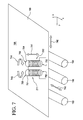
- FIG. 17 illustrates an exemplary coiled conductor of an electrical power monitoring system located on a surface of the electrical circuit breaker panel of FIG. 1 , according to an embodiment different from FIGS. 7 and 9-12 ;
- FIG. 18 illustrates an exemplary magnetic field sensor of an electrical power monitoring system located on a surface of panel of the electrical circuit breaker panel of FIG. 1 , according to an embodiment different from FIGS. 7, 9-12 , and 17 ;
- FIG. 19 is a graph illustrating phase angle of a received sign relative to the voltage versus position measured using the electrical power monitoring system of FIG. 18 , according an embodiment
- FIG. 20 illustrates a flow chart for an embodiment of a method of providing a system for monitoring electrical power usage of a structure, according to an embodiment
- FIG. 21 illustrates a flow chart for an embodiment of an activity of providing a sensing device, according to the embodiment of FIG. 20 ;
- FIG. 22 illustrates a flow chart for an embodiment of a method of using a system for monitoring electrical power usage of a structure, according to an embodiment.
- Couple should be broadly understood and refer to connecting two or more elements or signals, electrically, mechanically and/or otherwise.
- Two or more electrical elements may be electrically coupled but not be mechanically or otherwise coupled; two or more mechanical elements may be mechanically coupled, but not be electrically or otherwise coupled; two or more electrical elements may be mechanically coupled, but not be electrically or otherwise coupled.
- Coupling may be for any length of time, e.g., permanent or semi-permanent or only for an instant.
- Electrode coupling and the like should be broadly understood and include coupling involving any electrical signal, whether a power signal, a data signal, and/or other types or combinations of electrical signals.
- Mechanical coupling and the like should be broadly understood and include mechanical coupling of all types.
- Some embodiments can teach a system for monitoring usage of electrical power by a structure.
- the structure can have one or more main electrical power lines that supply the electrical power to a first load in the structure.
- a portion of the one or more main electrical power lines can run substantially parallel to a first axis.
- the structure can further have a panel that overlies the portion of the one or more main electrical power lines.
- the system can include: (a) a current sensor unit configured to be coupled to a portion of a surface of the panel, the current sensor unit having: (a) at least one magnetic field sensor having a length substantially parallel to a second axis, wherein the second axis is substantially perpendicular to the first axis, and the at least one magnetic field sensor is configured to detect a magnetic field generated by the one or more main electrical power lines; and (b) a processing unit configured to run on a processor.
- the current sensor unit can be configured to produce an output signal based on the magnetic field detected by the at least one magnetic field sensor.
- the processing unit further can be configured to receive the output signal from the current sensor unit and process the output signal to determine one or more parameters related to the usage of the electrical power by the first load in the structure.
- inventions can teach an apparatus for measuring electrical current in one or more main electrical power lines of a structure.
- the structure can have a breaker box.
- the breaker box can include at least a first part of the one or more main electrical power lines and a metal panel over the first part of the one or more main electrical power lines.
- the apparatus can include: (a) a sensing device having: (1) one or more electrical current sensors configured to provide two or more current measurements; and (2) one or more magnets coupled to the one or more electrical current sensors; and (b) a processing module configured to run on a computational unit and configured to use the two or more current measurements to determine the electrical current in the one or more main electrical power lines.
- the structure can have one or more main electrical power lines that supply the electrical power to a first load in the structure.
- the one or more main electrical power lines at least partially can run substantially parallel to a first axis.
- the structure can further having a panel that overlies at least part of the one or more main electrical power lines.
- the method can include: providing a current sensor unit configured to be coupled to a surface of the panel, the current sensor unit configured to produce an output signal based on a magnetic field generated by the one or more main electrical power lines; and providing a processing unit configured to receive the output signal from the current sensor unit and further configured to process the output signal to determine one or more parameters related to the usage of the electrical power of the structure.
- Providing the current sensor unit can include: providing at least one magnetic field sensor with a length along a second axis, wherein the at least one magnetic field sensor is configured to detect the magnetic field generated by the one or more main electrical power lines; and mounting the at least one magnetic field sensor at the current sensor unit such that the second axis of the at least one magnetic field sensor is substantially perpendicular to the first axis when the current sensor unit is coupled to the surface of the panel.
- Still further embodiments disclose a method for monitoring usage of electrical power of a structure using an electrical power monitoring system.
- the structure can have one or more main electrical power lines that supply the electrical power to a first load in the structure.
- the method can include: calibrating the electrical power monitoring system.
- a first raw current in the one or more main electrical power lines and first calibration data are generated while calibrating the electrical power monitoring system; storing the first calibration data and a measurement of the first raw current; measuring a second raw current; performing a first recalibration of the electrical power monitoring system if the second raw current is not within a predetermined amount of the first raw current; if the second raw current is within the predetermined amount of the first raw current, calculating the first measured current using the first calibration data; and displaying the first measured current.
- Performing the first recalibration of the electrical power monitoring system can include: calibrating the electrical power monitoring system, a third raw current in the one or more main electrical power lines and second calibration data are generated while performing the first recalibration of the electrical power monitoring system; storing the second calibration data and a measurement of the third raw current; and calculating a first measured current using the second calibration data.
- Additional embodiments can include an apparatus for measuring electrical current in one or more main electrical power lines of a structure.
- the structure can have a breaker box.
- the breaker box can include at least a first part of the one or more main electrical power lines and a metal panel over the first part of the one or more main electrical power lines.
- the apparatus can include a sensing device.
- the sensing device can include one or more electrical current sensors configured to provide two or more current measurements.
- the sensing device also can include one or more magnets coupled to the one or more electrical current sensors.
- the apparatus also can include a processing module configured to run on a computational unit and configured to use the two or more current measurements to determine the electrical current in the one or more main electrical power lines.
- Further embodiments can include a method for monitoring usage of electrical power of a structure using an electrical power monitoring system.
- the structure can have one or more main electrical power lines that supply the electrical power to a first load in the structure.
- the method can include calibrating the electrical power monitoring system.
- a first raw current in the one or more main electrical power lines and first calibration data can be generated while calibrating the electrical power monitoring system.
- the method also can include storing the first calibration data and a measurement of the first raw current.
- the method additionally can include measuring a second raw current.
- the method further can include calculating a first measured current.
- the method additionally can include displaying the first measured current.
- FIG. 1 illustrates a view of an exemplary electrical power monitoring system 100 coupled to an electrical breaker panel 190 , according to a first embodiment.
- FIG. 2 illustrates a block diagram of electrical power monitoring system 100 , according to the first embodiment.
- Electrical power monitoring system 100 can also be considered a system for monitoring electrical power usage of a structure. Electrical power monitoring system 100 is merely exemplary and is not limited to the embodiments presented herein. Electrical power monitoring system 100 can be employed in many different embodiments or examples not specifically depicted or described herein.
- electrical power monitoring system 100 can include: (a) a sensing device 110 ; (b) a computational unit 120 ; (c) a display device 130 ; and (d) a calibration device 180 .
- a conventional breaker box or circuit breaker panel 190 can include: (a) two or more individual circuit breakers 191 ; (b) two or more main circuit breakers 192 ; (c) main electrical power lines 193 , 194 , and 195 ; (d) a panel 196 with an exterior surface 198 ; and (e) a door 197 that provides access to circuit breakers 191 and 192 .
- Main electrical power lines 193 , 194 , and 195 are electrically coupled to main circuit breakers 192 and supply the electrical power to electrical devices (i.e., the load) in the structure.
- Panel 196 overlies at least part of main electrical power lines 193 , 194 , and 195 and associated circuitry to protect people from inadvertently contacting these energized conductors.
- panel 196 comprises steel or another metal.
- System 100 can determine the load current in main electrical power lines 193 , 194 , and 195 by positioning sensing device 110 at surface 198 of panel 196 and measuring the induced voltage in sensing device 110 . Electrical power monitoring system 100 can use the measured induced voltage to calculate the electrical current and electrical power in main electrical power lines 193 , 194 , and 195 .
- sensing device 110 it is possible to place sensing device 110 anywhere on surface 198 of panel 196 and accurately determine the current in each of the individual branches (including reactive loads).
- to obtain accurate current measurements requires that the magnetic fields from main electrical power lines 193 , 194 , and 195 to see the same reactance from panel 196 and sensing device 110 . If the reactance is not the same, it becomes more difficult to accurately calculate the electrical current and electrical power in main electrical power lines 193 , 194 , and 195 .
- FIG. 3 is a graph 300 illustrating the induced voltage versus conductor current for an exemplary electrical circuit breaker panel with a metal panel overlying the main electrical power lines.
- FIG. 4 is a graph 400 illustrating the induced voltage versus conductor current for an exemplary electrical circuit breaker panel where the metal panel has replaced with a cardboard panel.
- FIG. 5 is a three-dimensional graph 500 illustrating the voltage measured using a magnetic field sensor moved horizontally over an electrical conductor (x-axis) and at different heights above the conductor (y-axis) when a steel plate is placed between the conductor and the magnetic field sensor.
- FIG. 6 is a three-dimensional graph 600 illustrating the voltage measured using a magnetic field sensor moved horizontally over an electrical conductor (x-axis) and at different heights above the conductor (y-axis) without a steel plate between the conductor and the magnetic field sensor.
- FIGS. 2-6 the use of a metal panel overlying the main electrical power lines (i.e., panel 196 (FIG.
- electrical power monitoring system 100 can compensate or eliminate the non-linearity is the induced voltage in sensing device 110 caused by the use of metal in panel 196 . Moreover, electrical power monitoring system 100 can ensure that main electrical power lines 193 , 194 , and 195 see the same reactance from panel 196 and sensing device 110 .
- sensing device 110 can include: (a) two or more electrical current sensors or magnetic field sensors 211 and 212 ; (b) a controller 213 ; (c) a user communications module 214 ; (d) a transceiver 215 ; (e) a power source 216 ; and (f) a coupling mechanism 219 .
- Controller 213 can be used to control magnetic field sensors 211 and 212 , user communications module 214 , transceiver 215 and power source 216 .
- sensing device 110 can include two, four, six, or eight magnetic field sensors.
- magnetic field sensors 211 and 212 can be 2.5 millimeters (mm) to 12.7 mm in diameter.
- sensing device 110 can be configured to be coupled to surface 198 ( FIG. 1 ) of panel 196 ( FIG. 2 ) using coupling mechanism 219 .
- coupling mechanism 219 can include an adhesive, a Velcro® material, a magnet, or another attachment mechanism.
- magnetic field sensors 211 and 212 can include coiled conductors (e.g., coiled wires).
- FIG. 7 illustrates exemplary magnetic field sensors 211 located over surface 198 of panel 196 with main electrical power lines 193 , 194 , and 195 under panel 196 , according to the first embodiment.
- magnetic field sensor 211 can include a coiled conductor 751 with a first end 752 and a second end 753 opposite the first end 752 .
- coiled conductor 751 can be coiled in a first direction 743 (e.g., counter-clockwise).
- Magnetic field sensor 212 can include a coiled conductor 754 with a first end 755 and a second end 756 opposite the first end 755 .
- Coiled conductor 754 can be coiled in a second direction 744 (e.g., clockwise).
- the first direction 743 of the coiling of coiled conductor 751 can be opposite the second direction 744 of the coiling of coiled conductor 754 .
- Coiling the conductor in magnetic field sensors 211 and 212 can help eliminate the non-linearity in the magnetic field.
- coiled conductors 751 and 754 can be 2 millimeters (mm) to 12 mm in diameter. Coiled conductor 751 can be spaced apart from coiled conductor 754 by 12 mm to 40 mm. In some examples, the total width of two or more magnetic field sensors can be up to 160 mm. In some examples, coiled conductors can have an air core or a steel core.
- At least a portion of surface 198 can be substantially parallel to axes 740 and 742 with at least axis 740 substantially perpendicular to axis 742 .
- at least portion of main electrical power lines 193 , 194 , and 195 can run substantially parallel to axis 740 .
- axis 741 is substantially perpendicular to axes 740 and 742 .
- axis 741 can run along a length of coiled conductor 751 from first end 752 to second end 753 and along a length of coiled conductor 754 from first end 755 to second end 756 . That is, coiled conductors 751 and 754 can be substantially perpendicular to surface 198 and main electrical power lines 193 , 194 , and 195 .
- main electrical power lines 193 , 194 , and 195 see the substantially the same reactance from panel 196 and sensing device 110 . Furthermore, when an electrical power monitoring system has the configuration show in FIG. 7 , the steel plate and coiled conductors 751 and 754 have a constant reactance.
- a fixed current can be placed in main electrical power lines 193 , 194 , and 195 and coiled conductor 751 can be moved relative to main electrical power lines 193 , 194 , and 195 while measuring the phase angle of the received signal. If the reactance is constant, the measured phase angle in an ideal coil conductor will exhibit bistable behavior with only two phases that are 180° apart.
- FIG. 8 is a graph 800 illustrating phase angle of a received sign relative to the voltage versus position for electrical power monitoring system 100 , according an embodiment.
- a fixed current was placed in main electrical power lines 193 , 194 , and 195 and coiled conductor 751 was moved in approximately 0.6 centimeter (cm) increments relative to main electrical power lines 193 , 194 , and 195 while measuring the phase angle of the received signal relative to the voltage.
- the phase angle exhibits bistable behavior with has two different phases that are approximately 180° apart. The phase shift occurs when the coil conductor passed over the center of main electrical power line 195 .
- reactance of coiled conductor 751 and panel 196 as seen by main electrical power lines 193 , 194 , and 195 is substantially constant.
- transceiver 215 can be electrically coupled to magnetic field sensors 211 and 212 and controller 213 .
- transceiver 215 communicates the voltages or other parameters measured using magnetic field sensors 211 and 212 to transceiver 221 of computational unit 120 .
- transceiver 215 and transceiver 221 can be wireless transceivers.
- electrical signals can be transmitted using WI-FI (wireless fidelity), the IEEE (Institute of Electrical and Electronics Engineers) 802.11 wireless protocol or the Bluetooth 3.0+HS (High Speed) wireless protocol.
- these signals can be transmitted via a Zigbee (802.15.4), Z-Wave, or a proprietary wireless standard.
- transceiver 215 and transceiver 221 can communicate electrical signals using a cellular or wired connection.
- Computational unit 120 can include: (a) transceiver 221 ; (b) a processing module or unit 222 ; (c) a power source 223 ; (d) a user communications device 124 ; (e) a processor 225 ; (f) memory 226 ; (g) calibration module 227 ; and (h) electrical connector 128 .
- Computational unit 120 can be configured to receive the output signal from sensing device 110 via transceiver 221 and process the output signal to determine one or more parameters related to the electrical power usage of the structure (e.g., the electrical power used by the structure and the electrical current in main electrical power lines 193 , 194 , and 195 ).
- processing unit 222 can be stored in memory 226 and configured to run on processor 225 .
- Processing unit 222 can be further configured use the current measurements from sensing device 110 to determine one or more parameters related to the electrical power usage of the structure (e.g., the electrical current and electrical power of main electrical power lines 193 , 194 , and 195 ).
- program instructions stored in memory 226 are executed by processor 225 .
- a portion of the program instructions, stored in memory 226 can be suitable for carrying out method 2200 ( FIG. 22 ) as described below and/or processing unit 222 .
- Calibration module 227 can include one or more calibration loads.
- the one or more calibration loads can be electrically coupling to the first phase branch of the electrical power line infrastructure of structure to help calibrate electrical power monitoring system 100 using electrical connector 128 .
- User communications device 124 can be configured to display information to a user.
- user communications device 124 can be a monitor, a touch screen, and/or one or more LEDs (light emitting diodes).
- Power source 223 can provide electrical power to transceiver 221 , a user communications device 124 , a processor 225 , and memory 226 .
- power source 223 can include electrical plug 129 that can be coupled to an electrical wall outlet.
- Display device 130 can include (a) a display 134 ; (b) a control mechanism 132 ; (c) a transceiver 231 configured to communicate with transceiver 221 ; (d) power source 233 ; and/or (e) electrical connector 235 .
- electrical connector 235 can be configured to couple to electrical connector 128 to couple display device 130 to computational unit 120 .
- Calibration device 180 can include: (a) a transceiver 281 ; (b) an electrical connector 182 ; (c) a calibration module 283 ; and (d) a user communication device 184 .
- transceiver 281 can be similar or the same as transceivers 215 , 221 , and/or 231 .
- Electrical connector 182 can be an electrical power plug in some examples.
- User communication device 184 can be configured to display information to a user. In one example, user communication device 184 can be one or more LEDs.
- Calibration module 283 can include one or more calibration loads.
- the one or more calibration loads can be electrically coupling to the second phase branch of the electrical power line infrastructure of structure to help calibrate electrical power monitoring system 100 . That is, in some examples, electrical connector 128 is coupled to an electrical wall outlet coupled to the first phase of the electrical power (e.g. main electrical power line 193 or L 1 ) and electrical connector 182 is coupled to an electrical wall outlet coupled to the second phase of the electrical power (e.g. main electrical power line 194 or L 2 ). In these examples, main electrical power line 195 is the ground line.
- FIG. 9 illustrates exemplary magnetic field sensors 911 and 912 of electrical power monitoring system 900 located over surface 198 of panel 196 with main electrical power lines 193 , 194 , and 195 under panel 196 , according to an embodiment.
- Electrical power monitoring system 900 can also be considered a system for monitoring electrical power usage of a structure. Electrical power monitoring system 900 is merely exemplary and is not limited to the embodiments presented herein. Electrical power monitoring system 900 can be employed in many different embodiments or examples not specifically depicted or described herein.
- electrical power monitoring system 900 can include: (a) a sensing device 910 ; (b) a computational unit 120 ( FIGS. 1 and 2 ); (c) a display device 130 ( FIGS. 1 and 2 ); and (d) a calibration device 180 ( FIGS. 1 and 2 ).
- Sensing device 910 can include: (a) two or more electrical current sensors or magnetic field sensors 911 and 912 ; (b) magnet or magnetic cores 961 and 964 ; (c) a controller 213 ( FIG. 2 ); (d) a user communications module 214 ( FIG. 2 ); (e) a transceiver 215 ( FIG. 2 ); (f) a power source 216 ( FIG.
- Magnetic cores 961 and 964 can be considered part of or coupled to magnetic field sensors 911 and 912 .
- magnetic cores 961 and 964 can include an electromagnet or a permanent magnet.
- Magnetic cores 961 and 964 can be configured to help coupled sensing device 910 to surface 198 .
- the north and south poles of magnetic cores 961 and 964 can be located at the ends of the each magnetic core.
- magnetic field sensors 911 and 912 can include coiled conductors (e.g., coiled wires).
- magnetic field sensor 911 can include a coiled conductor 751 with a first end 752 and a second end 753 opposite the first end 752 .
- coiled conductor 751 can be coiled around magnetic core 961 in a first direction 743 (e.g., counter-clockwise).
- Magnetic field sensor 912 can include a coiled conductor 754 with a first end 755 and a second end 756 opposite the first end 755 .
- Coiled conductor 754 can be coiled around magnetic core 964 in a second direction 744 (e.g., clockwise).
- the first direction 743 of the coiling of coiled conductor 751 can be opposite the second direction 744 of the coiling of coiled conductor 754 .
- At least a portion of surface 198 can be substantially parallel to axes 740 and 742 with at least axis 740 substantially perpendicular to axis 742 .
- at least portion of main electrical power lines 193 , 194 , and 195 can run substantially parallel to axis 740 .
- axis 741 is substantially perpendicular to axes 740 and 742 . That is, coiled conductors 751 and 754 can be substantially perpendicular to surface 198 and main electrical power lines 193 , 194 , and 195 .
- one end of magnetic cores 961 and 964 can be configured to couple to surface 198 of panel 196 .
- magnetic cores 961 and 964 can help equalize the reactance of panel 196 and coiled conductors 951 and 954 by saturating the magnetic field in the region of panel 196 near magnetic cores 961 and 964 .
- reactance of coiled conductors 951 and 954 and panel 196 as seen by main electrical power lines 193 , 194 , and 195 is substantially constant and the non-linearity of the magnetic filed caused by panel 196 is substantially eliminated.
- FIG. 10 illustrates exemplary magnetic field sensors 1011 , 1012 , and 1019 of electrical power monitoring system 1000 located on surface 198 of panel 196 , according to an embodiment.
- Electrical power monitoring system 1000 can also be considered a system for monitoring electrical power usage of a structure. Electrical power monitoring system 1000 is merely exemplary and is not limited to the embodiments presented herein. Electrical power monitoring system 1000 can be employed in many different embodiments or examples not specifically depicted or described herein.
- electrical power monitoring system 1000 can include: (a) a sensing device 1010 ; (b) a computational unit 120 ( FIGS. 1 and 2 ); (c) a display device 130 ( FIGS. 1 and 2 ); and (d) a calibration unit 180 ( FIGS. 1 and 2 ).
- Sensing device 1010 can include: (a) two or more electrical current sensors or magnetic field sensors 1011 , 1012 , and 1019 ; (b) one or more magnets or magnetic cores 961 , 964 , and 1069 ; (c) a controller 213 ( FIG. 2 ); (d) a user communications module 214 ( FIG. 2 ); (e) a transceiver 215 ( FIG.
- magnetic field sensors 1011 , 1012 , and 1019 can include coiled conductors 751 , 754 , and 1059 , respectively.
- coiled conductor 1059 can be similar or the same as coiled conductors 751 and/or 754 .
- Coiled conductors 751 , 754 , and 1059 can be wrapped around magnetic cores 961 , 964 , and 1069 , respectively.
- magnetic cores 961 , 964 , and 1069 can be coupled to ferromagnetic cups or domes 1066 , 1067 , and 1068 .
- magnetic cores 961 , 964 , and 1069 can extend beyond coiled conductors 751 , 754 , and 1059 , respectively, and be coupled to ferromagnetic cups or domes 1066 , 1067 , and 1068 .
- Domes 1066 , 1067 , and 1068 can be located over coiled conductors 751 , 754 , and 1059 , respectively. That is, coiled conductors 751 , 754 , and 1059 are inside or enclosed by domes 1066 , 1067 , and 1068 , respectively. In some examples, the north and south poles of magnetic cores 961 , 964 , and 1069 can be located at the ends of the each magnetic core. Domes 1066 , 1067 , and 1068 can be made from steel or another ferromagnetic material.
- magnetic cores 961 , 964 , and 1069 can help equalize the reactance of panel 196 and coiled conductors 951 , 954 , and 1079 , respectively, by saturating the magnetic field in the region of panel 196 near coiled conductors 951 , 954 , and 1079 .
- Domes 1066 , 1067 , and 1068 can further focus the magnetic flux lines in the region around and/or below of magnetic cores 961 , 964 , and 1069 , respectively.
- the reactance of coiled conductors 951 , 954 , and 1079 and panel 196 as seen by main electrical power lines 193 , 194 , and 195 is substantially constant and the non-linearity of the magnetic field caused by panel 196 is eliminated.
- domes 1066 , 1067 , and 1068 can help decrease the cost of electrical power monitoring system 1000 . Because the magnetic field is more focused when domes 1066 , 1067 , and 1068 are used, magnetic cores 961 , 964 , and 1069 can be weaker magnets. Accordingly, electrical power monitoring systems with ferromagnetic domes can use less magnetic material or less costly (i.e., weaker) magnetic material.
- FIG. 11 illustrates exemplary magnetic field sensors 1111 , 1112 , and 1119 of electrical power monitoring system 1100 located on surface 198 of panel 196 , according to an embodiment.
- Electrical power monitoring system 1100 can also be considered a system for monitoring electrical power usage of a structure. Electrical power monitoring system 1100 is merely exemplary and is not limited to the embodiments presented herein. Electrical power monitoring system 1100 can be employed in many different embodiments or examples not specifically depicted or described herein.
- Electrical power monitoring system 1100 can be similar or the same as electrical power monitoring system 1000 except that ferromagnetic domes 1066 , 1067 , and 1068 are replaced by a single ferromagnetic dome 1166 enclosing coiled conductors 751 , 754 , and 1059 .
- using one ferromagnetic dome instead of individual ferromagnetic domes over each of the coiled conductors can decrease the cost of the electrical power monitoring system.
- FIG. 12 illustrates an exemplary magnetic field sensors 1211 of electrical power monitoring system 1200 located on surface 198 of panel 196 , according to an embodiment.
- Electrical power monitoring system 1200 can also be considered a system for monitoring electrical power usage of a structure.
- Electrical power monitoring system 1200 is merely exemplary and is not limited to the embodiments presented herein.
- Electrical power monitoring system 1200 can be employed in many different embodiments or examples not specifically depicted or described herein.
- electrical power monitoring system 1200 can include: (a) a sensing device 1210 ; (b) a computational unit 120 ( FIGS. 1 and 2 ); (c) a display device 130 ( FIGS. 1 and 2 ); and (d) a calibration unit 180 ( FIGS. 1 and 2 ).
- Sensing device 1210 can include: (a) at least one electrical current sensor or magnetic field sensor 1211 ; (b) magnet 1261 ; (c) a controller 213 ( FIG. 2 ); (d) a user communications module 214 ( FIG. 2 ); (e) a transceiver 215 ( FIG. 2 ); (f) a power source 216 ( FIG. 2 ); and (g) a coupling mechanism 219 ( FIG. 2 ).
- Magnet 1261 can be considered part of or coupled to magnetic field sensors 1211 . In some examples, magnet 1261 is configured to magnetically couple sensing device 1210 to panel 196 .
- magnetic field sensors 1211 can include coiled conductors (e.g., coiled wires). In many embodiments, magnetic field sensor 1211 can include a coiled conductor 751 . In some examples, coiled conductor 751 can be coiled in a first direction 743 (e.g., counter-clockwise). In the embodiment shown in FIG. 12 , axis 741 is substantially perpendicular to axes 740 and 742 . That is, the length of coiled conductor 751 running from first end 752 to second end 753 can be substantially perpendicular to surface 198 and main electrical power lines 193 , 194 , and 195 .
- Magnet 1261 can have a first side 1248 and a second side 1249 opposite the first side 1248 .
- Second side 1249 can be adjacent to surface 198 of panel 196 .
- first end 752 of coiled conductor 751 can be coupled to or adjacent to first side 1248 of magnet 1261 .
- Second end 753 can be spaced apart from first side 1248 of magnet 1261 .
- magnet 1261 can help equalize the reactance of coiled conductor 751 and panel 196 as seen by main electrical power lines 193 , 194 , and 195 by saturating the magnetic field in the region of panel 196 near coiled conductor 751 .
- the reactance of coiled conductor 751 and panel 196 as seen by main electrical power lines 193 , 194 , and 195 is substantially constant and the non-linearity of the magnetic filed caused by panel 196 is eliminated.
- FIG. 13 is a graph 1300 illustrating an induced voltage versus a conductor current for an exemplary electrical circuit breaker panel with a metal panel overlying the main electrical power lines, according to an embodiment. That is, graph 1300 illustrates the induced voltage versus the conductor current for a sensing device substantially similar to sensing device 1210 and a sensing device substantially similar to sensing device 1210 but without magnet 1261 . As illustrated in FIG. 13 , the use of magnet 1261 in sensing device 1210 greatly increases the linearity of the induced voltage.
- FIG. 14 is a graph 1400 illustrating a phase angle of a received signal (relative to the voltage) versus the position, according an embodiment.
- a fixed current was placed in main electrical power lines 193 , 194 , and 195 and a sensing device was moved in approximately 0.6 centimeter increments relative to main electrical power lines 193 , 194 , and 195 while the phase angle of the received signal relative to the voltage was measured.
- Graph 1400 illustrates the induced voltage versus position for sensing device substantially similar to sensing device 1210 and a sensing device substantially similar to sensing device 1210 but without magnet 1261 . As shown in FIG.
- the phase angle exhibits a much sharper phase angle shift when a sensing device 1210 with magnet 1261 is used. In the region where the phase angle is shifting, it is difficult to measure the phase angle and thus current measurements in these areas can have a higher error rate. By increasing the sharpness of the phase angle shift, the area at which sensing device 1210 provides useable results is greatly increased.
- FIGS. 15 and 16 illustrate the results of two additional test scenarios that show the improved accuracy of electrical power monitoring system 1200 compared to an electrical power monitoring system without a magnet.
- FIG. 15 illustrates a graph 1500 showing the result of using an electrical power monitoring system with a vertically mounted coiled conductor but without a magnet, according to an embodiment.
- FIG. 16 illustrates a graph 1600 showing the result of using an electrical power monitoring system 1200 (i.e., a vertically mounted coiled conductor with a magnet), according to an embodiment.
- FIG. 17 illustrates exemplary coiled conductor 751 of electrical power monitoring system 1700 located on surface 198 of panel 196 , according to an embodiment.
- Electrical power monitoring system 1700 can also be considered a system for monitoring electrical power usage of a structure.
- Electrical power monitoring system 1700 is merely exemplary and is not limited to the embodiments presented herein.
- Electrical power monitoring system 1700 can be employed in many different embodiments or examples not specifically depicted or described herein.
- Electrical power monitoring system 1700 can be similar or the same as electrical power monitoring system 1200 except electrical power monitoring system 1700 include a ferromagnetic dome 1766 over coiled conductor 751 .
- the ends of dome 1766 are located at magnet 1261 .
- magnet 1261 is also enclosed by dome 1766 .
- the use of dome 1766 in electrical power monitoring system 1200 can focus the magnetic flux lines in the region around and/or below coiled conductor 751 .
- FIG. 18 illustrates exemplary magnetic field sensor 1811 of electrical power monitoring system 1800 located on surface 198 of panel 196 with main electrical power lines 193 , 194 , and 195 under panel 196 , according to an embodiment.
- Electrical power monitoring system 1800 can also be considered a system for monitoring electrical power usage of a structure. Electrical power monitoring system 1800 is merely exemplary and is not limited to the embodiments presented herein. Electrical power monitoring system 1800 can be employed in many different embodiments or examples not specifically depicted or described herein.
- electrical power monitoring system 1800 can include: (a) a sensing device 1810 ; (b) a computational unit 120 ( FIGS. 1 and 2 ); (c) a display device 130 ( FIGS. 1 and 2 ); and (d) a calibration unit 180 ( FIGS. 1 and 2 ).
- Sensing device 1810 can include: (a) at least one electrical current sensor or magnetic field sensor 1811 ; (b) a controller 213 ( FIG. 2 ); (c) a user communications module 214 ( FIG. 2 ); (d) a transceiver 215 ( FIG. 2 ); (e) a power source 216 ( FIG. 2 ); and (f) a coupling mechanism 219 ( FIG. 2 ).
- magnetic field sensor 1811 can include a coiled conductor 1851 with a first end 1852 and a second end 1853 opposite the first end 1852 .
- a length of coiled conductor 1851 from end 1852 to 1853 can be substantially perpendicular to axis 742 . That is, coiled conductor 1851 can be substantially perpendicular to main electrical power lines 193 , 194 , and 195 and substantially parallel to surface 198 .
- main electrical power lines 193 , 194 , and 195 see a substantially constant reactance from panel 196 and coiled conductor 951 .
- FIG. 19 is a graph 1900 illustrating a phase angle of a received sign relative to the voltage versus a position of magnetic filed sensor 1811 , according an embodiment.
- a fixed current was placed in main electrical power lines 193 , 194 , and 195 and coil conductor 1851 was moved in approximately 0.6 centimeter increments relative to main electrical power lines 193 , 194 , and 195 while the phase angle of the received signal relative to the voltage was measured.
- the phase angle exhibits bistable behavior with has two different phases approximately 180° apart. The 180° phase shift occurs when the coil passes over the center of main electrical power line 195 .
- reactance of coil conductor 1851 and panel 196 as seen by main electrical power lines 193 , 194 , and 195 is substantially constant and the non-linearity of the magnetic filed caused by panel 196 is eliminated.
- FIG. 20 illustrates a flow chart for an embodiment of a method 2000 of providing a system for monitoring electrical power usage of a structure.
- Method 2000 is merely exemplary and is not limited to the embodiments presented herein. Method 2000 can be employed in many different embodiments or examples not specifically depicted or described herein.
- the activities, the procedures, and/or the processes of method 2000 can be performed in the order presented. In other embodiments, the activities, the procedures, and/or the processes of the method 2000 can be performed in any other suitable order. In still other embodiments, one or more of the activities, the procedures, and/or the processes in method 2000 can be combined or skipped.
- method 2000 includes an activity 2061 of providing a sensing device.
- the sensing device can be similar or identical sensing devices 110 , 910 , 1010 , 1210 , and 1810 of FIGS. 1, 9, 10, 12, and 18 , respectively.
- the sensing device can be configured to be coupled to a surface of the panel of an electrical breaker box.
- the sensing device can be configured to produce an output signal based on the magnetic field generated by one or more main electrical power lines in the electrical breaker box.
- FIG. 21 illustrates a flow chart for an embodiment of activity 2061 of providing a sensing device, according to the first embodiment.
- activity 2061 includes a procedure 2171 of providing one or more magnetic field sensors.
- the magnetic filed sensors can be similar to magnetic field sensors 211 and 212 of FIG. 2 , magnetic field sensors 911 and 912 of FIG. 9 , magnetic field sensor 1011 , 1012 , 1019 of FIG. 10 , magnetic field sensor 1211 of FIG. 12 , and/or magnetic field sensor 1811 of FIG. 18 .
- the one or more magnetic field sensors can include one or more coiled conductors.
- activity 2061 of FIG. 21 includes a procedure 2172 of mounting the one or more magnetic field sensors to the sensing device.
- procedure 2172 can include mounting the one or more magnetic field sensors at the sensing device such that an axis of the one or more magnetic field sensors are substantially perpendicular to a least a portion of one or more main electrical power lines and substantially parallel to the surface of the panel when the sensing device is coupled to the surface of the panel.
- procedure 2172 can include mounting the one or more magnetic field sensors at the sensing device such that an axis of the one or more magnetic field sensors are substantially perpendicular to a least a portion of one or more main electrical power lines and substantially perpendicular the surface of the panel when the sensing device is coupled to the surface of the panel.
- the one or more magnetic field sensors at the sensing device are mounted such that an axis of the one or more magnetic field sensors are substantially perpendicular to a portion of one or more main electrical power lines directly below the magnetic field sensors and substantially perpendicular the surface of the panel when the sensing device is coupled to the surface of the panel
- Activity 2061 in FIG. 21 continues with a procedure 2173 of providing one or more magnets.
- the one or more magnets can be similar to magnetic cores 961 and 964 of FIG. 9 , magnetic core 1069 of FIG. 10 , and/or magnet 1261 of FIG. 12 .
- activity 2061 of FIG. 21 includes a procedure 2174 of coupling the one or more magnets to the one or more magnetic sensors.
- coupling one or more magnetic sensors to the one or more magnets can include wrapping the one or more coiled conductors of the magnetic fields sensors around the one or more magnets.
- the coiled conductors of the magnetic fields sensors can be wrapped around the one or more magnets can be similar to the coiled conductors wrapped around the one or more magnets as shown in FIGS. 9, 10 , and/or 11 .
- coupling one or more magnetic sensors to the one or more magnets can include coupling one end of the magnetic field sensor to the one or more magnets.
- coupling one end of the magnetic fields sensors to the one or more magnets can be similar to the coupling one end of the magnetic fields sensors to the one or more magnets as shown in FIGS. 12 , and/or 13 .
- activity 2061 does not include procedures 2173 and 2174 .
- activity 2061 of FIG. 21 includes a procedure 2175 of providing one or more ferromagnetic domes.
- the one or more ferromagnetic domes can be similar to domes 1066 , 1067 , and 1068 of FIG. 10 , dome 1166 of FIG. 11 and/or dome 1766 of FIG. 16 .
- Activity 2061 in FIG. 21 continues with a procedure 2176 of mounting the one or more ferromagnetic domes such that the one or more magnetic field sensors are located within the one or more domes.
- the one or more magnetic field sensors located within the one or more domes can be similar to the one or more magnetic field sensors located within the one or more domes as shown in FIGS. 10, 11 , and/or 16 .
- activity 2061 does not include procedures 2175 and 2176 .
- activity 2061 of FIG. 21 includes a procedure 2177 of providing one or more additional components of the sensing device.
- the one or more additional components can include a controller, a power source, a transceiver, a user communications module, and/or a coupling mechanism.
- method 2000 in FIG. 20 continues with an activity 2062 of providing a computational device.
- the computational device can be similar or identical computational unit 120 of FIGS. 1 and 2 .
- activity 2062 can, instead, include just providing a processing unit.
- the processing unit can be similar or identical processing unit 222 of FIG. 2 .
- the processing unit can be configured to receive the output signal from the sensing device and further configured to process the output signal to determine one or more parameters related to the electrical power usage of the structure.
- method 2000 of FIG. 20 includes an activity 2063 of providing a calibration device.
- the calibration device can be similar or identical calibration device 180 of FIGS. 1 and 2 .
- method 2000 of FIG. 20 includes an activity 2064 of providing a display device.
- the calibration device can be similar or identical display device 130 of FIGS. 1 and 2 .
- the display device can be part of computational unit 120 .
- FIG. 22 illustrates a flow chart for an embodiment of a method 2200 of using a system for monitoring electrical power usage of a first load of a structure.
- Method 2200 is merely exemplary and is not limited to the embodiments presented herein. Method 2200 can be employed in many different embodiments or examples not specifically depicted or described herein.
- the activities, the procedures, and/or the processes of method 2200 can be performed in the order presented. In other embodiments, the activities, the procedures, and/or the processes of the method 2200 can be performed in any other suitable order. In still other embodiments, one or more of the activities, the procedures, and/or the processes in method 2200 can be combined or skipped.
- method 2200 includes an activity 2261 of providing an electrical power monitoring system.
- the electrical power monitoring system can be similar or identical to electrical power monitoring systems 100 , 900 , 1000 , 1100 , 1200 , 1700 , and 1800 of FIGS. 1, 9, 10, 11, 12, 17 , and 18 , respectively.
- Method 2200 in FIG. 22 continues with an activity 2262 of calibrating the electrical power monitoring system.
- a first calibration can be preformed when the electrical power monitoring system is first installed or powered-up.
- a computational device of the electrical power monitoring system is plugged into a first phase line (e.g., L 1 ) of the electrical power system of the structure and a calibration device of the electrical power monitoring system is plugged into a second phase line (e.g., L 2 ) of the electrical power system of the structure.
- calibrating the electrical power monitoring system can first include determining a first amplitude and a first phase of a first current in each of the current sensors of the sensing device. Afterwards, a first load in the computational device is coupled to the first phase branch and a second amplitude and a second phase of a second current in each of the current sensors of the sensing device are determined. Next, a second predetermined load in the calibration device is coupled to the second phase branch and a third amplitude and a third phase of a third current in each of the current sensors are determined. Finally, one or more calibration factors are determined for the sensing device at least in part using the first amplitudes, the first phases, the second amplitudes, the second phases, the third amplitudes, and the third phases.
- method 2200 of FIG. 22 includes an activity 2263 of storing the calibration data.
- the calibration data can include the calibration factors and the first amplitude and the first phase of a first current.
- the calibration data can be stored in memory in the computational device.
- method 2200 of FIG. 22 includes an activity 2264 of measuring a raw current.
- Method 2200 in FIG. 22 continues with an activity 2265 of determining if the raw current different by a predetermined amount from stored calibration data. If the current is within a predetermined amount of the current of the stored calibration data, the next activity is activity 2266 of calculating the measure current.
- the next activity is activity 2262 of calibrating the electrical power monitoring system.
- the new calibration parameters and new first current can be stored in memory.
- a database of calibration data and raw currents can be created.
- the raw current can be compared to all of the calibration data stored in the memory. If the raw current is not within a predetermined amount of the stored calibration data, the electrical power monitoring system can be recalibrated. That is, a new calibration would occur anytime electrical power monitoring system detects that a large change in the current has occurred from previously measured currents. Thus, the non-linearity in the magnetic field can be mitigated by re-calibrating the electrical power monitoring system anytime a large change in the current of the main electrical power lines occurs.
- method 2200 of FIG. 22 includes an activity 2266 of calculating the measured current using the stored calibration data.
- method 2200 continues with an activity 2267 of displaying the measured current.
- the measured current can be displayed using display device 130 .
- activities 2261 , 2262 , 2263 , 2264 , 2265 , 2266 , 2267 of FIG. 22 may be comprised of many different activities, procedures and be performed by many different modules, in many different orders that any element of FIGS. 1, 2, 7, 9, 10, 11, 12, 17, and 18 may be modified and that the foregoing discussion of certain of these embodiments does not necessarily represent a complete description of all possible embodiments.
- embodiments and limitations disclosed herein are not dedicated to the public under the doctrine of dedication if the embodiments and/or limitations: (1) are not expressly claimed in the claims; and (2) are or are potentially equivalents of express elements and/or limitations in the claims under the doctrine of equivalents.
Abstract
Description
Claims (20)
Priority Applications (1)
| Application Number | Priority Date | Filing Date | Title |
|---|---|---|---|
| US15/966,779 US10459012B2 (en) | 2010-07-02 | 2018-04-30 | System for monitoring electrical power usage of a structure and method of same |
Applications Claiming Priority (5)
| Application Number | Priority Date | Filing Date | Title |
|---|---|---|---|
| US36129610P | 2010-07-02 | 2010-07-02 | |
| US38017410P | 2010-09-03 | 2010-09-03 | |
| US13/175,774 US8972211B2 (en) | 2010-07-02 | 2011-07-01 | System for monitoring electrical power usage of a structure and method of same |
| US14/635,824 US20150168464A1 (en) | 2010-07-02 | 2015-03-02 | System for monitoring electrical power usage of a structure and method of same |
| US15/966,779 US10459012B2 (en) | 2010-07-02 | 2018-04-30 | System for monitoring electrical power usage of a structure and method of same |
Related Parent Applications (1)
| Application Number | Title | Priority Date | Filing Date |
|---|---|---|---|
| US14/635,824 Division US20150168464A1 (en) | 2010-07-02 | 2015-03-02 | System for monitoring electrical power usage of a structure and method of same |
Publications (2)
| Publication Number | Publication Date |
|---|---|
| US20180252751A1 US20180252751A1 (en) | 2018-09-06 |
| US10459012B2 true US10459012B2 (en) | 2019-10-29 |
Family
ID=45402689
Family Applications (5)
| Application Number | Title | Priority Date | Filing Date |
|---|---|---|---|
| US13/175,770 Active 2030-03-31 US8805628B2 (en) | 2009-09-25 | 2011-07-01 | Systems and methods for measuring electrical power usage in a structure and systems and methods of calibrating the same |
| US13/175,774 Expired - Fee Related US8972211B2 (en) | 2010-07-02 | 2011-07-01 | System for monitoring electrical power usage of a structure and method of same |
| US14/457,032 Active 2030-05-11 US9594098B2 (en) | 2009-09-25 | 2014-08-11 | Systems and methods for measuring electrical power usage in a structure and systems and methods of calibrating the same |
| US14/635,824 Abandoned US20150168464A1 (en) | 2010-07-02 | 2015-03-02 | System for monitoring electrical power usage of a structure and method of same |
| US15/966,779 Expired - Fee Related US10459012B2 (en) | 2010-07-02 | 2018-04-30 | System for monitoring electrical power usage of a structure and method of same |
Family Applications Before (4)
| Application Number | Title | Priority Date | Filing Date |
|---|---|---|---|
| US13/175,770 Active 2030-03-31 US8805628B2 (en) | 2009-09-25 | 2011-07-01 | Systems and methods for measuring electrical power usage in a structure and systems and methods of calibrating the same |
| US13/175,774 Expired - Fee Related US8972211B2 (en) | 2010-07-02 | 2011-07-01 | System for monitoring electrical power usage of a structure and method of same |
| US14/457,032 Active 2030-05-11 US9594098B2 (en) | 2009-09-25 | 2014-08-11 | Systems and methods for measuring electrical power usage in a structure and systems and methods of calibrating the same |
| US14/635,824 Abandoned US20150168464A1 (en) | 2010-07-02 | 2015-03-02 | System for monitoring electrical power usage of a structure and method of same |
Country Status (13)
| Country | Link |
|---|---|
| US (5) | US8805628B2 (en) |
| EP (2) | EP2591372A4 (en) |
| JP (5) | JP2013531802A (en) |
| KR (3) | KR101507663B1 (en) |
| CN (3) | CN106093554B (en) |
| AU (2) | AU2011274385B2 (en) |
| BR (2) | BR112013000048B1 (en) |
| CA (4) | CA3035892C (en) |
| EA (4) | EA035040B1 (en) |
| HK (1) | HK1182177A1 (en) |
| MX (4) | MX2013000239A (en) |
| NZ (3) | NZ704116A (en) |
| WO (2) | WO2012003492A2 (en) |
Families Citing this family (70)
| Publication number | Priority date | Publication date | Assignee | Title |
|---|---|---|---|---|
| US8094034B2 (en) | 2007-09-18 | 2012-01-10 | Georgia Tech Research Corporation | Detecting actuation of electrical devices using electrical noise over a power line |
| GB0816721D0 (en) | 2008-09-13 | 2008-10-22 | Daniel Simon R | Systems,devices and methods for electricity provision,usage monitoring,analysis and enabling improvements in efficiency |
| US9766277B2 (en) * | 2009-09-25 | 2017-09-19 | Belkin International, Inc. | Self-calibrating contactless power consumption sensing |
| CA3035892C (en) | 2010-07-02 | 2021-06-29 | Belkin International, Inc. | Systems and methods for measuring electrical power usage in a structure and systems and methods of calibrating the same |
| WO2012003426A2 (en) | 2010-07-02 | 2012-01-05 | Reynolds Brett S | Apparatus for calibrated non-invasive measurement of electrical current |
| US9291694B2 (en) | 2010-07-02 | 2016-03-22 | Belkin International, Inc. | System and method for monitoring electrical power usage in an electrical power infrastructure of a building |
| US8738195B2 (en) * | 2010-09-21 | 2014-05-27 | Intel Corporation | Inferencing energy usage from voltage droop |
| US8718964B2 (en) | 2011-04-01 | 2014-05-06 | Wilsun Xu | Method and system for calibrating current sensors |
| US9256908B2 (en) * | 2011-08-19 | 2016-02-09 | International Business Machines Corporation | Utility consumption disaggregation using low sample rate smart meters |
| WO2013106922A1 (en) * | 2012-01-19 | 2013-07-25 | Awesense Wireless Inc. | System and method for linear measurement of ac waveforms with low voltage non-linear sensors in high voltage environments |
| FR2987680B1 (en) * | 2012-03-05 | 2014-03-14 | Smartfuture | METHOD FOR MEASURING CURRENT IN AN ELECTRICITY NETWORK |
| US20130271895A1 (en) * | 2012-04-12 | 2013-10-17 | Hampden Kuhns | User installable branch circuit meter |
| US8907658B2 (en) * | 2012-04-19 | 2014-12-09 | Kohler, Inc. | System and method of measuring power produced by a power source |
| US8442792B1 (en) | 2012-10-26 | 2013-05-14 | Elbex Video Ltd. | Method and apparatus for calibrating intelligent AC outlets |
| US10083255B2 (en) * | 2012-12-14 | 2018-09-25 | Honeywell International Inc. | Equipment fault detection, diagnostics and disaggregation system |
| US20140210460A1 (en) * | 2013-01-30 | 2014-07-31 | Hampden Kuhns | Contactless electric meter reading devices |
| US9329659B2 (en) * | 2013-02-06 | 2016-05-03 | Veris Industries, Llc | Power monitoring system that determines frequency and phase relationships |
| US9291656B2 (en) * | 2013-02-13 | 2016-03-22 | Merck Sharp & Dohme Corp. | Device for calibrating and verifying the integrity of resistivity-based sensing probes |
| US9869705B2 (en) * | 2013-03-15 | 2018-01-16 | Insight Energy Ventures Llc | Magnetometer sampling to determine an electric power parameter |
| KR101458983B1 (en) * | 2013-04-29 | 2014-11-10 | 코원에너지서비스 주식회사 | Digital remote control and supervisory circuit for a rectifier |
| US9354271B2 (en) * | 2013-05-10 | 2016-05-31 | Alarm.Com Incorporated | Multi-node electrical power monitoring, analysis, and related services |
| US9857414B1 (en) | 2013-05-10 | 2018-01-02 | Alarm.Com Incorporated | Monitoring and fault detection of electrical appliances for ambient intelligence |
| KR101319449B1 (en) * | 2013-05-28 | 2013-10-16 | (주) 에코센스 | Power measurement apparatus to accomplish a wireless routing |
| FR3007143B1 (en) * | 2013-06-17 | 2015-07-17 | Schneider Electric Ind Sas | SYSTEM FOR CALCULATING AN ELECTRICAL SIZE, TRANSFORMATION STATION COMPRISING SUCH A SYSTEM AND METHOD OF CALCULATING AN ELECTRICAL SIZE WITH SUCH A SYSTEM |
| US20150008911A1 (en) * | 2013-07-05 | 2015-01-08 | Alan Majer | Apparatus for sensing current from electrical appliances |
| US10707038B2 (en) * | 2013-09-06 | 2020-07-07 | Texas Instruments Incorporated | System and method for energy monitoring |
| CN103592484B (en) * | 2013-11-04 | 2016-04-20 | 江苏林洋能源股份有限公司 | A kind of electricity anti-theft method for anti-strong magnet, electronic electric energy meter being produced to error effect |
| US8698426B1 (en) * | 2013-11-06 | 2014-04-15 | Neilsen-Kuljian, Inc. | Self-powered current sensing switch with digital setpoint |
| CN103630862A (en) * | 2013-11-19 | 2014-03-12 | 中国西电电气股份有限公司 | Non-standard square coil for magnetic field immunity test and calibrating method and calibrating system of non-standard square coil |
| US9784774B2 (en) * | 2014-01-06 | 2017-10-10 | The Nielsen Company (Us), Llc | Methods and apparatus to determine an operational status of a device |
| US10401401B2 (en) | 2014-03-31 | 2019-09-03 | Panoramic Power Ltd. | System and methods thereof for monitoring of energy consumption cycles |
| WO2015167400A1 (en) * | 2014-04-30 | 2015-11-05 | Illinois At Singapore Pte Ltd | An electric meter, an electric meter system and a method of providing branch-level readings for a power distribution network |
| JP6458375B2 (en) * | 2014-07-03 | 2019-01-30 | 日産自動車株式会社 | Impedance measuring device |
| WO2016040883A1 (en) * | 2014-09-12 | 2016-03-17 | Belkin International, Inc. | Self-calibrating contactless power consumption sensing |
| US20180306846A1 (en) * | 2014-11-21 | 2018-10-25 | The Regents Of The University Of California | Non-contact electricity meters |
| US9658264B2 (en) | 2014-12-30 | 2017-05-23 | Energybox Ltd. | Energy metering system with self-powered sensors |
| US9995815B2 (en) * | 2014-12-30 | 2018-06-12 | Energybox Ltd. | Energy metering system and method for its calibration |
| US10467354B2 (en) * | 2014-12-30 | 2019-11-05 | Energybox Ltd. | Visualization of electrical loads |
| US10288646B2 (en) | 2015-02-26 | 2019-05-14 | Potential Labs, Llc | Determining energy usage of a residence based on current monitoring |
| GB2538087B (en) * | 2015-05-06 | 2019-03-06 | Torro Ventures Ltd | Analysing a power circuit |
| CN104950281B (en) * | 2015-07-03 | 2017-12-19 | 朗亿德电气股份有限公司 | High-voltage electric energy meter amendment box, high voltage electric energy amplitude correction detecting system and method |
| US20180321350A1 (en) * | 2015-09-24 | 2018-11-08 | Whisker Labs, Inc. | Remote sensing to derive calibrated power measurements |
| KR20180059500A (en) * | 2015-09-24 | 2018-06-04 | 어스네트웍스 아이엔씨 | Remote sensing to derive calibrated power measurements |
| WO2017152243A1 (en) * | 2016-03-11 | 2017-09-14 | Dius Computing Pty Ltd | A power sensor and method for determining power use of an associated appliance |
| AU2017329013B2 (en) * | 2016-09-19 | 2021-09-09 | Panduit Corp. | Voltage indicator display module |
| KR20180041276A (en) * | 2016-10-13 | 2018-04-24 | 주식회사 에스앤에이 | Power measurement apparatus having hall sensor for robbery prevention of electrical power and robbery prevention method of electrical power therefor |
| CN108120920A (en) * | 2016-11-28 | 2018-06-05 | 中车大同电力机车有限公司 | A kind of main circuit breaker of railway engine device for detecting performance |
| EP3578954A4 (en) * | 2017-02-01 | 2020-12-30 | Tokyo Electric Power Company Holdings, Incorporated | Sensor holding device and sensor holding system |
| CN106872759B (en) * | 2017-02-24 | 2019-04-05 | 广东顺德工业设计研究院(广东顺德创新设计研究院) | Current path detection device and current path detection method |
| US10557873B2 (en) * | 2017-07-19 | 2020-02-11 | Allegro Microsystems, Llc | Systems and methods for closed loop current sensing |
| US10514399B1 (en) | 2017-08-08 | 2019-12-24 | II Donald P. Orofino | Measurement of alternating electric current via electromagnetic dynamic sensor measurements |
| WO2019038733A1 (en) * | 2017-08-25 | 2019-02-28 | 3M Innovative Properties Company | Temperature-corrected control data for verifying of structural integrity of materials |
| US10502807B2 (en) | 2017-09-05 | 2019-12-10 | Fluke Corporation | Calibration system for voltage measurement devices |
| US11016129B1 (en) * | 2017-10-20 | 2021-05-25 | Alarm.Com Incorporated | Voltage event tracking and classification |
| TWI635289B (en) | 2017-11-17 | 2018-09-11 | 財團法人工業技術研究院 | Sensing method for power consumption and sensing device |
| US20200333866A1 (en) * | 2017-11-18 | 2020-10-22 | Christopher Dunbar | End user controlled load management system |
| US10879698B2 (en) * | 2017-11-30 | 2020-12-29 | Abb Schweiz Ag | Systems and methods for performing building power management |
| KR102009578B1 (en) * | 2017-12-27 | 2019-08-09 | (주) 씨에스엠 | Measuring method for at least one load for electric heater control |
| US10466277B1 (en) | 2018-02-01 | 2019-11-05 | John Brooks | Scaled and precise power conductor and current monitoring |
| KR102535063B1 (en) * | 2018-04-06 | 2023-05-22 | 엘지전자 주식회사 | Device and cloud server providing safty service by distinguishing electrothermic device |
| CN109061524B (en) * | 2018-09-25 | 2021-09-17 | 湖南国科微电子股份有限公司 | Power supply test circuit and method |
| JP2020095029A (en) * | 2018-12-12 | 2020-06-18 | メレキシス テクノロジーズ エス エーMelexis Technologies SA | Current sensor |
| AU2019401591A1 (en) * | 2018-12-17 | 2021-07-22 | Apparent Labs, LLC | Sensor-based energy management enclosure and distributed energy resource management based on sensor data |
| WO2020184361A1 (en) * | 2019-03-13 | 2020-09-17 | 日本電産リード株式会社 | Detection value correction system, coefficient calculating method, and detection value correction method |
| US10983178B2 (en) * | 2019-05-17 | 2021-04-20 | Honeywell International Inc. | Active sensor circuitry |
| WO2021064738A1 (en) * | 2019-10-03 | 2021-04-08 | Selec Controls Private Limited | A measurement apparatus and a method for correcting measures therefrom |
| WO2021180307A1 (en) * | 2020-03-10 | 2021-09-16 | Eaton Intelligent Power Limited | Power usage in an electricity distribution apparatus for a plurality of electrical loads |
| CN113884755A (en) * | 2020-07-03 | 2022-01-04 | 绿铜科技公司 | System and method for setting up a sensor system |
| CN115616277B (en) * | 2022-01-10 | 2023-09-22 | 荣耀终端有限公司 | Monitoring circuit and monitoring system |
| KR102439182B1 (en) * | 2022-02-21 | 2022-09-01 | 주식회사 한국이알이시 | Switchgear (high-voltage panel, low-voltage panel, motor control panel, distribution panel) Equipped with an Initial Fire Extinguishing Device |
Citations (225)
| Publication number | Priority date | Publication date | Assignee | Title |
|---|---|---|---|---|
| US3714516A (en) | 1972-01-26 | 1973-01-30 | P Howe | Meter socket voltage recorder unit |
| US4012734A (en) | 1974-12-23 | 1977-03-15 | American Science & Engineering, Inc. | Synchronous power communicating |
| US4612617A (en) | 1983-03-02 | 1986-09-16 | Siemens-Allis, Inc. | Method and apparatus for monitoring instantaneous electrical parameters of a power distribution system |
| EP0200312A1 (en) | 1985-03-13 | 1986-11-05 | RAYCHEM CORPORATION (a Delaware corporation) | Phase difference fault detector |
| US4638417A (en) | 1985-08-16 | 1987-01-20 | Sperry Corporation | Power density spectrum controller |
| US4706073A (en) | 1984-09-25 | 1987-11-10 | Oscar Vila Masot | Circuit breaker panels with alarm system |
| US4716409A (en) | 1986-07-16 | 1987-12-29 | Homestead Products, Inc. | Electrical appliance control system |
| US4804957A (en) | 1985-11-27 | 1989-02-14 | Triad Communications, Inc. | Utility meter and submetering system |
| US4858141A (en) | 1986-04-14 | 1989-08-15 | Massachusetts Institute Of Technology | Non-intrusive appliance monitor apparatus |
| US4891587A (en) | 1986-09-30 | 1990-01-02 | National Research Development Corporation | Magnetic field sensor using variations in ultrasound to determine magnetic field |
| GB2228337A (en) | 1989-02-18 | 1990-08-22 | Diehl Gmbh & Co | Hall-effect apparatus for measuring direct current |
| JPH02212780A (en) | 1989-02-13 | 1990-08-23 | Nippondenso Co Ltd | Processing apparatus of sensor signal |
| FR2645968A1 (en) | 1989-04-18 | 1990-10-19 | Electricite De France | Method and apparatus for analysing current and voltage signals with a view to identifying loads for household use |
| GB2235304A (en) | 1989-08-01 | 1991-02-27 | Landis & Gyr Betriebs Ag | Monitoring the consumption of electrical energy |
| JPH0450786A (en) | 1990-06-19 | 1992-02-19 | Fujitsu Ltd | Pickup coil for magnetic field detection |
| US5177560A (en) | 1991-11-06 | 1993-01-05 | Hewlett-Packard Company | Optical spectrum analyzer having adjustable sensitivity |
| WO1993004377A1 (en) | 1991-08-27 | 1993-03-04 | Services Industriels De Geneve | Method for identifying electrical power consumers on a circuit being monitored |
| US5229753A (en) | 1991-06-10 | 1993-07-20 | Berg Richard P | Warning device for a washing apparatus which advises whether its contents are clean or soiled |
| US5233342A (en) | 1990-06-01 | 1993-08-03 | Pioneer Electronic Corporation | Remote control system |
| US5268666A (en) | 1991-12-23 | 1993-12-07 | At&T Bell Laboratories | Appliance control system providing out-of-context usage |
| US5276629A (en) | 1990-06-21 | 1994-01-04 | Reynolds Software, Inc. | Method and apparatus for wave analysis and event recognition |
| JPH0712976A (en) | 1993-06-18 | 1995-01-17 | Ishikawajima Harima Heavy Ind Co Ltd | Pressure vessel |
| US5409037A (en) | 1994-06-06 | 1995-04-25 | Wheeler; Jaye F. | Automatic device for the detection and shutoff of excess water flow in pipes |
| US5428342A (en) | 1991-04-25 | 1995-06-27 | Hitachi, Ltd. | Analyzing system for operating condition of electrical apparatus |
| US5441070A (en) | 1993-11-10 | 1995-08-15 | Thompson; Gary E. | Fluid management system |
| US5467011A (en) | 1992-05-06 | 1995-11-14 | National Rural Electric Cooperative Assn. | System for detection of the phase of an electrical signal on an alternating circuit power line |
| US5483153A (en) | 1994-03-24 | 1996-01-09 | Massachusetts Institute Of Technology | Transient event detector for use in nonintrusive load monitoring systems |
| US5483838A (en) | 1993-12-29 | 1996-01-16 | Holden; Edward S. | Fluid flow connector and gauge assembly |
| US5495168A (en) | 1994-09-12 | 1996-02-27 | Fluke Corporation | Method of signal analysis employing histograms to establish stable, scaled displays in oscilloscopes |
| US5534663A (en) | 1994-11-14 | 1996-07-09 | The United States Of America As Represented By The United States Department Of Energy | Electrically shielded enclosure with magnetically retained removable cover |
| KR960024384A (en) | 1994-12-24 | 1996-07-20 | 유채준 | Multi-function power supply unit with remote control and monitoring |
| US5590179A (en) | 1993-02-12 | 1996-12-31 | Ekstrom Industries, Inc. | Remote automatic meter reading apparatus |
| US5600310A (en) | 1994-12-02 | 1997-02-04 | General Electric Company | Serial bus control for appliances |
| JPH09130961A (en) | 1995-10-31 | 1997-05-16 | Kyushu Electric Power Co Inc | Method and apparatus for supervising power line |
| US5635895A (en) | 1994-02-14 | 1997-06-03 | Murr; William C. | Remote power cost display system |
| US5650771A (en) | 1995-04-25 | 1997-07-22 | Lee; Chung-Cheng | Electrical socket with monitoring unit for monitoring operating conditions |
| US5699276A (en) | 1995-12-15 | 1997-12-16 | Roos; Charles E. | Utility meter providing an interface between a digital network and home electronics |
| US5717325A (en) | 1994-03-24 | 1998-02-10 | Massachusetts Institute Of Technology | Multiprocessing transient event detector for use in a nonintrusive electrical load monitoring system |
| US5808846A (en) | 1995-07-11 | 1998-09-15 | Veris Industries, Inc. | Combination current sensor and relay |
| JPH10282161A (en) | 1997-04-09 | 1998-10-23 | Matsushita Electric Ind Co Ltd | Power consumption monitoring system |
| KR19980069423A (en) | 1997-02-28 | 1998-10-26 | 이대원 | Electrical Equipment Fault Diagnosis Device Using Frequency Characteristics and Its Method |
| US5880677A (en) | 1996-10-15 | 1999-03-09 | Lestician; Guy J. | System for monitoring and controlling electrical consumption, including transceiver communicator control apparatus and alternating current control apparatus |
| US5898387A (en) | 1997-03-26 | 1999-04-27 | Scientific-Atlanta, Inc. | Modular meter based utility gateway enclosure |
| US5929315A (en) | 1995-10-31 | 1999-07-27 | Dunegan; Harold L. | Measuring crack growth by acoustic emission |
| US6094043A (en) | 1998-04-15 | 2000-07-25 | Square D Company | ARC detection sensor utilizing discrete inductors |
| JP2000258482A (en) | 1999-03-08 | 2000-09-22 | Toshiba Corp | Frequency inspection device |
| US6137283A (en) | 1995-02-22 | 2000-10-24 | Michael K. Williams | Process and machine for signal waveform analysis |
| US6147484A (en) | 1998-07-08 | 2000-11-14 | Smith; Richard T. | Device for measuring power using switchable impedance |
| US6173613B1 (en) | 1996-04-30 | 2001-01-16 | Harold L. Dunegan | Measuring crack growth by acoustic emission |
| JP2001103622A (en) | 1999-09-28 | 2001-04-13 | Osaki Electric Co Ltd | Measuring system of subscriber's private electrical energy |
| US20010003286A1 (en) | 1999-07-14 | 2001-06-14 | Jay E. Philippbar | Flood control device |
| WO2001050142A1 (en) | 1999-12-29 | 2001-07-12 | Abb Service S.R.L. | An improved current sensing device for low-voltage power circuit breakers |
| JP2001190506A (en) | 2000-01-17 | 2001-07-17 | Nippon Colin Co Ltd | Arterial sclerosis evaluating device |
| US6275168B1 (en) | 1997-05-23 | 2001-08-14 | Siemens Power Transmission And Distribution, Llc | Expansion module for modular meter |
| US6273686B1 (en) | 1999-01-29 | 2001-08-14 | A. Roemheld Gmbh & Co Kg | Apparatus and method for controlling a rated system pressure |
| EP1136829A1 (en) | 2000-03-22 | 2001-09-26 | Conseil en Technologies Innovantes | Method for measuring the consumption of an element of an electrical network |
| US6310470B1 (en) | 1997-04-19 | 2001-10-30 | Lust Antriebstechnik Gmbh | Method and device for measuring the difference in magnetic field strength with magnetoresistive sensors |
| US6320968B1 (en) | 2000-06-28 | 2001-11-20 | Esion-Tech, Llc | Adaptive noise rejection system and method |
| US6330516B1 (en) | 2000-03-27 | 2001-12-11 | Power Distribution, Inc. | Branch circuit monitor |
| US20020010690A1 (en) | 1998-02-23 | 2002-01-24 | Howell Doanld Wayne | Energy information system and sub-measurement board for use therewith |
| US20020036492A1 (en) | 2000-04-07 | 2002-03-28 | Slater Byron J. | Electronic meter having random access memory with passive nonvolatility |
| US6418083B1 (en) | 2001-01-12 | 2002-07-09 | The United States Of America As Represented By The Secretary Of The Navy | Phase fluctuation based signal processor |
| US6420969B1 (en) | 2000-05-10 | 2002-07-16 | Kirk Campbell | Appliance alarm system |
| CN1379860A (en) | 1999-08-06 | 2002-11-13 | 森泰克有限公司 | Current sensor |
| WO2003003029A2 (en) | 2001-06-28 | 2003-01-09 | Trendpoint Systems, Inc. | A method and apparatus for reading and controlling electric power consumption |
| RU2200364C2 (en) | 1996-12-09 | 2003-03-10 | Тарджет-Хай-Тек Электроникс Лтд. | Device for uniform distribution of electric load among phases in n-phase power distribution network |
| US20030050737A1 (en) | 2001-09-10 | 2003-03-13 | Robert Osann | Energy-smart home system |
| US20030088527A1 (en) | 2001-11-06 | 2003-05-08 | General Electric Company | Methods and systems for monitoring water usage |
| US20030088374A1 (en) | 2001-09-25 | 2003-05-08 | Slater Byron J. | Arrangement for providing sensor calibration information in a modular utility meter |
| US20030097348A1 (en) | 2001-11-20 | 2003-05-22 | Lipeng Cao | Modeling behavior of an electrical circuit |
| US20030112370A1 (en) | 2001-12-18 | 2003-06-19 | Chris Long | Adaptive expanded information capacity for communications systems |
| US20030151406A1 (en) | 2002-02-11 | 2003-08-14 | Hong Wan | Magnetic field sensor |
| US20030158677A1 (en) | 2000-02-29 | 2003-08-21 | Swarztrauber Sayre A. | System and method for on-line monitoring and billing of power consumption |
| US6614211B1 (en) | 1999-04-01 | 2003-09-02 | Santronics, Inc. | Non-contact detector for sensing a periodically varying magnetic field |
| US20030184280A1 (en) | 2001-11-30 | 2003-10-02 | Marc Bowman | Power monitoring system |
| US20030193405A1 (en) | 2002-04-15 | 2003-10-16 | Hunt Power, L.P. | User-installable power consumption monitoring system |
| US20030216877A1 (en) | 2002-05-17 | 2003-11-20 | Culler Mark Frederick | Method and system for measuring current |
| US6678209B1 (en) | 2001-11-21 | 2004-01-13 | Luc Peng | Apparatus and method for detecting sonar signals in a noisy environment |
| US20040027138A1 (en) | 2002-08-07 | 2004-02-12 | Pickerd John J. | Oscilloscope based return loss analyzer |
| JP2004132790A (en) | 2002-10-09 | 2004-04-30 | Fuji Electric Holdings Co Ltd | Current sensor |
| US6734806B1 (en) | 1999-07-15 | 2004-05-11 | Cratsley, Iii Charles W. | Method and system for signaling utility usage |
| CN1495432A (en) | 2002-09-12 | 2004-05-12 | Abb | Equipment and method for measuring current |
| CN1509410A (en) | 2001-04-12 | 2004-06-30 | ��Τ����˹ | Utility usage rate monitor |
| US20040128034A1 (en) | 2002-12-11 | 2004-07-01 | Lenker Jay A. | Method and apparatus for water flow sensing and control |
| US6771078B1 (en) | 1999-04-12 | 2004-08-03 | Chk Wireless Technologies Australia Pty. Ltd. | Apparatus and method for fault detection on conductors |
| JP2004219365A (en) | 2003-01-17 | 2004-08-05 | Osaki Electric Co Ltd | Electric current signal detector |
| US20040196024A1 (en) | 2002-09-20 | 2004-10-07 | Jason Stauth | Integrated current sensor |
| KR20040087036A (en) | 2003-04-04 | 2004-10-13 | 서효성 | The diagnostic system of radiation signal of electrical power equipment, its method and a diagnostic method for a dangerous condition of abnormal signals |
| US20040206405A1 (en) | 2003-01-17 | 2004-10-21 | Smith Lee Anthony | Residential water management system (RWMS) |
| JP2004296663A (en) | 2003-03-26 | 2004-10-21 | Denso Corp | Semiconductor device |
| US6816078B2 (en) | 2000-04-12 | 2004-11-09 | Central Research Institute Of Electric Power Industry | System and method for estimating power consumption of electric apparatus, and abnormality alarm system utilizing the same |
| US20040229578A1 (en) | 2003-05-12 | 2004-11-18 | Power Measurement Ltd. | Wireless communications system incorporating intelligent electronic devices |
| US20040251897A1 (en) | 2003-06-16 | 2004-12-16 | Danmag Aps | Fluxgate magnetometer with rotating core |
| US6839644B1 (en) | 2002-04-01 | 2005-01-04 | The Texas A&M University System | Plumbing supply monitoring, modeling and sizing system and method |
| US20050001486A1 (en) | 2001-08-09 | 2005-01-06 | Astropower, Inc. | Power and/or energy monitor, method of using, and display device |
| US6853291B1 (en) | 1998-02-20 | 2005-02-08 | Wrap S.P.A. | System device and method for monitoring electric users, particularly household appliances |
| US6860288B2 (en) | 2001-12-21 | 2005-03-01 | Kenneth J. Uhler | System and method for monitoring and controlling utility systems |
| US20050060107A1 (en) | 2003-09-16 | 2005-03-17 | Rodenberg Ernest Adolph | Programmable electricity consumption monitoring system and method |
| US20050067049A1 (en) | 2002-09-23 | 2005-03-31 | Fima Raoul G. | Systems and methods for monitoring and controlling water consumption |
| US6906617B1 (en) | 2000-11-17 | 2005-06-14 | Koninklijke Philips Electronics N.V. | Intelligent appliance home network |
| JP2005195427A (en) | 2004-01-06 | 2005-07-21 | Asahi Kasei Electronics Co Ltd | Current measurement system, current measurement method, and current measurement program |
| US6949921B1 (en) | 2001-10-26 | 2005-09-27 | E.O. Schweitzer Manufacturing Co., Llc | Auto-calibration of multiple trip settings in a fault indicator |
| US20060009928A1 (en) | 2000-06-05 | 2006-01-12 | Aqua Conserve, Inc. | Methods and apparatus for using water use signatures and water pressure in improving water use efficiency |
| JP2006062512A (en) | 2004-08-26 | 2006-03-09 | Sumitomo Metal Ind Ltd | Air spring height adjusting mechanism for rolling stock and control method of the air spring height adjusting mechanism |
| US20060050447A1 (en) | 2004-09-09 | 2006-03-09 | Pellon Christian V | Apparatus for detecting arc faults |
| US20060049831A1 (en) | 2004-09-04 | 2006-03-09 | Applied Materials, Inc. | Detection and suppression of electrical arcing |
| US7019666B2 (en) | 2002-06-10 | 2006-03-28 | Tantalus Systems Corp. | Adapter for a meter |
| US20060077046A1 (en) | 2004-10-06 | 2006-04-13 | Canon Kabushiki Kaisha | Power-line communication device |
| US7078996B1 (en) | 2005-05-20 | 2006-07-18 | Ambient Corporation | Inductive coupler for power line communications |
| US20060195275A1 (en) | 2005-02-15 | 2006-08-31 | Latham Christopher B T | Usage monitoring apparatus |
| US20060220833A1 (en) | 2005-04-04 | 2006-10-05 | Berkman William H | Power line communications system and method |
| US7119533B2 (en) | 2004-09-29 | 2006-10-10 | C & N, Inc. | Method, system and device for calibrating a magnetic field sensor |
| US20060226958A1 (en) | 2005-03-16 | 2006-10-12 | Domosys Corporation | System and method for power line communication |
| US20060245467A1 (en) | 2005-04-08 | 2006-11-02 | Casella Michael H | Apparatus, system and method for monitoring, recording and billing for individual fixture and unit water usage in a multi-unit structure |
| US7133729B1 (en) | 1999-08-17 | 2006-11-07 | Microsoft Corporation | Pattern-and model-based power line monitoring |
| US7134568B2 (en) | 2004-07-23 | 2006-11-14 | Honda Motor Co., Ltd. | Fuel tank system |
| US20060259201A1 (en) | 1992-11-17 | 2006-11-16 | Health Hero Network, Inc. | Home power management system |
| US20060284613A1 (en) | 2003-10-01 | 2006-12-21 | Hastings Jerome K | Magnetic flux concentrator anti-differential current sensor |
| US20070014369A1 (en) | 2005-07-12 | 2007-01-18 | John Santhoff | Ultra-wideband communications system and method |
| US7174260B2 (en) | 2004-04-01 | 2007-02-06 | Blue Line Innovations Inc. | System and method for reading power meters |
| US20070067003A1 (en) | 2005-09-14 | 2007-03-22 | University Of Florida Research Foundation, Inc. | Closed-loop micro-control system for predicting and preventing epilectic seizures |
| US20070064377A1 (en) | 2005-09-12 | 2007-03-22 | Deboer John | Panel layout for an integrated power distribution system |
| US20070085534A1 (en) | 2005-10-14 | 2007-04-19 | Yusuke Seki | Magnetic detection coil and apparatus for measurement of magnetic field |
| JP2007107972A (en) | 2005-10-12 | 2007-04-26 | Denso Corp | Current sensor |
| US20070114987A1 (en) | 2005-10-28 | 2007-05-24 | Electro Industries/Gauge Tech. | Intelligent electronic device for providing broadband Internet access |
| US20070132458A1 (en) | 2005-12-08 | 2007-06-14 | Allen Philip B Jr | Voltage indicator test mechanism |
| US20070152864A1 (en) | 2005-12-30 | 2007-07-05 | Bookham Technology Plc | Photodiode digitizer with fast gain switching |
| US7276915B1 (en) | 2005-02-01 | 2007-10-02 | Sprint Communications Company L.P. | Electrical service monitoring system |
| US20070230094A1 (en) | 2006-04-04 | 2007-10-04 | Carlson Curt S | Integrated, self-contained power distribution system |
| US20070237441A1 (en) | 2006-04-05 | 2007-10-11 | Photonic Systems, Inc. | Method and Apparatus for Determining Frequency-Dependent VPI of a Mach-Zehnder Optical Modulator |
| US20080030075A1 (en) | 2006-08-04 | 2008-02-07 | Stanley Gerald R | Powering a wireless system from preexisting power |
| US20080042636A1 (en) | 2006-08-18 | 2008-02-21 | General Electric Company | System and method for current sensing |
| US20080082276A1 (en) | 2006-09-28 | 2008-04-03 | Cecil Rivers | System for power sub-metering |
| US20080079437A1 (en) | 2006-09-28 | 2008-04-03 | General Electric Company | Current Sensing Module and Assembly Method Thereof |
| US20080086394A1 (en) | 2006-06-29 | 2008-04-10 | Carina Technology, Inc. | System and method for controlling a utility meter |
| US20080091345A1 (en) | 2006-06-28 | 2008-04-17 | Patel Shwetak N | Sub-room-level indoor location system using power line positioning |
| US20080106241A1 (en) | 2006-11-02 | 2008-05-08 | Deaver Brian J | Method and System for Providing Power Factor Correction in a Power Distribution System |
| JP2008122083A (en) | 2006-11-08 | 2008-05-29 | Hamamatsu Koden Kk | Current sensor |
| US20080167755A1 (en) | 2007-01-09 | 2008-07-10 | Power Monitors Inc. | Method and apparatus for smart circuit breaker |
| US20080172192A1 (en) * | 2005-01-27 | 2008-07-17 | Electro Industries/Gauge Tech. | Intelligent Electronic Device with Board-Range High Accuracy |
| US20080224892A1 (en) | 2007-03-16 | 2008-09-18 | I-Conserve, Llc | System and method for monitoring and estimating energy resource consumption |
| US20080234983A1 (en) | 2007-03-22 | 2008-09-25 | Commtest Instruments Limited | Method and system for vibration signal processing |
| US20080255782A1 (en) | 2007-04-12 | 2008-10-16 | Siemens Energy & Automation, Inc. | Devices, Systems, and Methods for Monitoring Energy Systems |
| US7460930B1 (en) | 2004-05-14 | 2008-12-02 | Admmicro Properties, Llc | Energy management system and method to monitor and control multiple sub-loads |
| WO2008150458A1 (en) | 2007-06-01 | 2008-12-11 | Wagner Charles G | Method and apparatus for monitoring power consumption |
| WO2008153577A1 (en) | 2007-06-15 | 2008-12-18 | General Electric Company | Micro-electromechanical system based switching in heating-ventilation-air-conditioning systems |
| WO2008153576A1 (en) | 2007-06-15 | 2008-12-18 | General Electric Company | Mems based motor starter with motor failure detection |
| KR20080114143A (en) | 2007-06-27 | 2008-12-31 | 전자부품연구원 | System for real-time monitoring the quantity of energy use using mesh sensor network modules |
| DE102007032053A1 (en) | 2007-07-10 | 2009-01-15 | Abröll, Andreas | Electrical device e.g. refrigerator, current consumption controlling apparatus, has learning device for collecting and evaluating data relative to usage of device, and controller for controlling operation of device based on data evaluation |
| US20090043520A1 (en) | 2006-08-10 | 2009-02-12 | V2Green, Inc. | User Interface and User Control in a Power Aggregation System for Distributed Electric Resources |
| US20090045804A1 (en) | 2007-08-14 | 2009-02-19 | General Electric Company | Cognitive electric power meter |
| US7498935B2 (en) | 2002-01-24 | 2009-03-03 | Panasonic Corporation | Power-line carrier communication apparatus |
| US20090070058A1 (en) | 2007-08-14 | 2009-03-12 | American Gnc Corporation | Miniaturized smart self-calibration electronic pointing method and system |
| CN201210170Y (en) | 2008-09-28 | 2009-03-18 | 张宝宏 | Multifunctional electric grid examine integrated tester |
| US20090072985A1 (en) | 2007-09-18 | 2009-03-19 | Georgia Tech Research Corporation | Detecting actuation of electrical devices using electrical noise over a power line |
| US7511229B2 (en) | 2005-06-02 | 2009-03-31 | Liebert Corporation | Sensor module, system, and method for sensors in proximity to circuit breakers |
| WO2009040140A1 (en) | 2007-09-21 | 2009-04-02 | Siemens Aktiengesellschaft | Decentralized energy system and method for distributing energy in a decentralized energy system |
| US20090115620A1 (en) | 2007-09-10 | 2009-05-07 | Phillip Hunter | Current switch with automatic calibration |
| WO2009063397A2 (en) | 2007-11-12 | 2009-05-22 | Eon Consulting (Proprietary) Limited | Method, apparatus and system for demand side electrical load management |
| JP2009130961A (en) | 2007-11-20 | 2009-06-11 | Denso Corp | Vehicular power unit |
| WO2009081407A2 (en) | 2007-12-26 | 2009-07-02 | Greenlet Technologies Ltd. | Reducing power consumption in a network by detecting electrical signatures of appliances |
| US20090224754A1 (en) | 2008-03-06 | 2009-09-10 | Jonathan Lamarre | Two-terminal linear sensor |
| US20090240449A1 (en) | 2007-12-20 | 2009-09-24 | Tollgrade Communications, Inc. | Power Distribution Monitoring System And Method |
| CN101562074A (en) | 2008-04-16 | 2009-10-21 | 邹长江 | Coil type current transformer |
| US20090312968A1 (en) | 2008-06-13 | 2009-12-17 | Alertme.Com.Ltd | Power consumption feedback systems |
| CN101632292A (en) | 2006-12-21 | 2010-01-20 | 赛普拉斯环境系统公司 | Gauge reading device and system |
| GB2461915A (en) | 2008-07-17 | 2010-01-20 | Isis Innovation | Utility meter |
| WO2010007369A2 (en) | 2008-07-17 | 2010-01-21 | Isis Innovation Limited | Utility metering |
| US7656649B2 (en) | 2007-12-26 | 2010-02-02 | Elster Electricity, Llc | Mechanical packaging apparatus and methods for an electrical energy meter |
| US20100030393A1 (en) | 2008-07-29 | 2010-02-04 | Masters Gilbert J | Apparatus Using Time-Based Electrical Characteristics to Identify an Electrical Appliance |
| US20100049456A1 (en) | 2007-10-18 | 2010-02-25 | Intellimeter Canada, Inc. | Electrical Power Metering Device and Method of Operation Thereof |
| US20100070218A1 (en) | 2008-09-18 | 2010-03-18 | Searete Llc, A Limited Liability Corporation Of The State Of Delaware | System and method for identifying appliances by electrical characteristics |
| US20100070214A1 (en) | 2008-09-18 | 2010-03-18 | Searete Llc, A Limited Liability Corporation Of The State Of Delaware | System and method for identifying appliances by electrical characteristics |
| KR20100032534A (en) | 2008-09-18 | 2010-03-26 | 한국전력공사 | Method, electronic watt hour meter for minimizing a measuring error |
| US20100088057A1 (en) | 2008-10-07 | 2010-04-08 | Kopaczewski Peter | Method for detection of a physical variable by way of a circuit breaker |
| US7702421B2 (en) | 2007-08-27 | 2010-04-20 | Honeywell International Inc. | Remote HVAC control with building floor plan tool |
| US7705484B2 (en) | 2007-04-10 | 2010-04-27 | Whirlpool Corporation | Energy management system and method |
| US7706928B1 (en) | 2005-09-07 | 2010-04-27 | Admmicro Properties, Llc | Energy management system with security system interface |
| GB2464927A (en) | 2008-10-28 | 2010-05-05 | Isis Innovation | Apparatus and method for metering the use of electricity |
| US20100109842A1 (en) | 2006-06-28 | 2010-05-06 | Patel Shwetak N | Sub room level indoor location system using wideband power line positioning |
| GB2465367A (en) | 2008-11-13 | 2010-05-19 | Isis Innovation | Non-intrusive electricity metering identifying individual loads from current waveform analysis |
| JP2010112936A (en) | 2008-11-10 | 2010-05-20 | Daido Steel Co Ltd | Current sensor and magnetic detection method |
| US7728986B2 (en) | 2004-04-13 | 2010-06-01 | The Trustees Of Columbia University In The City Of New York | Systems and methods for digital detection of a tomographic signal |
| US7729993B2 (en) | 2001-01-17 | 2010-06-01 | Smart Disaster Response Technologies, Inc. | Methods, apparatus, media, and signals for billing utility usage |
| GB2465800A (en) | 2008-12-01 | 2010-06-02 | Joyce Foster | Utility Consumption Apparatus |
| WO2010062398A1 (en) | 2008-11-26 | 2010-06-03 | Maloney Michael A | Power distribution controller and related systems and methods |
| US7747357B2 (en) | 2006-11-13 | 2010-06-29 | Lutron Electronics Co., Inc. | Method of communicating a command for load shedding of a load control system |
| US7755347B1 (en) | 2007-06-12 | 2010-07-13 | Geist Manufacturing Inc. | Current and voltage measurement device |
| US20100188262A1 (en) | 2007-07-19 | 2010-07-29 | Koninklijke Philips Electronics N.V. | Energy consumption measurement |
| US20100219808A1 (en) | 2009-02-27 | 2010-09-02 | Andrew Steckley | System for intelligent automated response to line frequency and voltage disturbances by a central control point communication with a plurality of load control devices |
| US7795877B2 (en) | 2006-11-02 | 2010-09-14 | Current Technologies, Llc | Power line communication and power distribution parameter measurement system and method |
| RU2402023C1 (en) | 2009-09-28 | 2010-10-20 | Государственное образовательное учреждение высшего профессионального образования "Российская таможенная академия" | Device to control power consumption |
| US20100264731A1 (en) | 2009-04-16 | 2010-10-21 | International Buisness Machines Corporation | Power conversion, control, and distribution system |
| US20100280392A1 (en) | 2007-09-21 | 2010-11-04 | Kan-Zhi Liu | Method and apparatus for periodontal diagnosis |
| US20110004421A1 (en) | 2008-02-21 | 2011-01-06 | Sentec Limited | Method of inference of appliance usage. data processing apparatus and/or computer software |
| US7885917B2 (en) | 2006-05-26 | 2011-02-08 | Board Of Regents Of The Nevada System Of Higher Education, On Behalf Of The Desert Research Institute | Utility monitoring and disaggregation systems and methods of use |
| US20110037444A1 (en) | 2009-08-11 | 2011-02-17 | Astec International Limited | Bridgeless Boost PFC Circuits and Systems With Reduced Common Mode EMI |
| US20110043374A1 (en) | 2007-07-09 | 2011-02-24 | Semitech Innovarins Pty Ltd | Communication methods and devices |
| US20110050218A1 (en) | 2009-08-28 | 2011-03-03 | Lohss Kurt L | non-contact magnetic current sensing and distribution system for determining individual power readings from a plurality of power sources |
| WO2011035301A2 (en) | 2009-09-21 | 2011-03-24 | Rutgers, The State University Of New Jersey | System and method for measuring consumption in a residential or commercial building via a wall socket |
| US20110074382A1 (en) | 2009-09-25 | 2011-03-31 | University Of Washington | Whole structure contactless power consumption sensing |
| US20110098949A1 (en) | 2009-10-26 | 2011-04-28 | Vennelakanti V S S K | System and method for handling wide dynamic range signals encountered in vibration analysis using a logarithmic amplifier |
| US20110112780A1 (en) | 2009-11-06 | 2011-05-12 | David Moss | Electrical power consumption measuring system |
| WO2011057049A1 (en) | 2009-11-06 | 2011-05-12 | Massachusetts Institute Of Technology | Non-intrusive monitoring of power and other parameters |
| US7982596B2 (en) | 2006-09-01 | 2011-07-19 | Power Monitors, Inc. | Method and apparatus for a power line communications test system |
| US20110194705A1 (en) | 2010-02-10 | 2011-08-11 | Nxp B.V. | System and method for adapting a loudspeaker signal |
| WO2011104661A1 (en) | 2010-02-25 | 2011-09-01 | Koninklijke Philips Electronics N.V. | Monitoring of operational status of appliances |
| US20110218746A1 (en) | 2010-03-08 | 2011-09-08 | Ls Industrial Systems Co., Ltd. | Apparatus and method for detecting power |
| US20110249181A1 (en) | 2010-04-09 | 2011-10-13 | Sony Corporation | Transmitting device, receiving device, control method, and communication system |
| WO2012003426A2 (en) | 2010-07-02 | 2012-01-05 | Reynolds Brett S | Apparatus for calibrated non-invasive measurement of electrical current |
| US8093765B1 (en) | 2003-06-03 | 2012-01-10 | Cypress Semiconductor Corporation | System for noise reduction in circuits |
| US20120041696A1 (en) | 2010-08-10 | 2012-02-16 | Sensus Usa Inc. | Electric Utility Meter To Stimulate Enhanced Functionality |
| US20120072389A1 (en) | 2010-09-21 | 2012-03-22 | Aldridge Tomm V | Inferencing energy usage from voltage droop |
| US20120072143A1 (en) | 2010-07-02 | 2012-03-22 | Belkin International, Inc. | System for Monitoring Electrical Power Usage of a Structure and Method of Same |
| US8195423B2 (en) | 2007-07-03 | 2012-06-05 | Nxp, B.V. | Calibration of an AMR sensor |
| US20120215410A1 (en) | 2003-03-20 | 2012-08-23 | Mcclure John A | Gnss based control for dispensing material from vehicle |
| US20120293146A1 (en) | 2011-05-18 | 2012-11-22 | Bcd Semiconductor Manufacturing Limited | Control circuit and method for audible noise suppression in a power converter |
| US8325817B2 (en) | 2006-05-17 | 2012-12-04 | Sony Corporation | Communication apparatus and method for data interpolation |
| US20130119972A1 (en) | 2010-07-02 | 2013-05-16 | Belkin International, Inc. | System and method for monitoring electrical power usage in an electrical power infrastructure of a building |
| US20130179124A1 (en) | 2007-09-18 | 2013-07-11 | Shwetak N. Patel | Electrical event detection device and method of detecting and classifying electrical power usage |
| KR101318982B1 (en) | 2013-05-10 | 2013-10-16 | (주) 에코센스 | Uninterruptible power measurement apparatus to measure power for variable power lines |
| US8664564B2 (en) | 2007-05-04 | 2014-03-04 | Illinois Tool Works Inc. | Controlled harmonics power supply for welding-type system |
| US8924604B2 (en) | 2011-09-26 | 2014-12-30 | Belkin International, Inc. | Systems and methods for data compression and feature extraction for the purpose of disaggregating loads on an electrical network |
| US20150002137A1 (en) | 2009-09-25 | 2015-01-01 | Belkin International, Inc. | Self-calibrating contactless power consumption sensing |
| WO2016040883A1 (en) | 2014-09-12 | 2016-03-17 | Belkin International, Inc. | Self-calibrating contactless power consumption sensing |
Family Cites Families (18)
| Publication number | Priority date | Publication date | Assignee | Title |
|---|---|---|---|---|
| JPH01190506A (en) * | 1988-01-26 | 1989-07-31 | Takeshi Ikeda | Air-pressure detecting device for automobile tire |
| JPH04296663A (en) * | 1991-03-27 | 1992-10-21 | Osaka Gas Co Ltd | Current measuring device |
| JPH0662512A (en) * | 1992-08-04 | 1994-03-04 | Matsushita Electric Works Ltd | Panel box |
| JPH0712976U (en) * | 1993-05-31 | 1995-03-03 | 日新電機株式会社 | Current measuring device |
| JPH10153625A (en) * | 1996-11-20 | 1998-06-09 | Daikin Ind Ltd | Input-current detecting circuit using current transformer |
| JP3813330B2 (en) * | 1997-09-29 | 2006-08-23 | 日置電機株式会社 | Measurement cable |
| JP2001153895A (en) * | 1999-11-24 | 2001-06-08 | Makome Kenkyusho:Kk | Current sensor |
| JP2001161009A (en) * | 1999-11-30 | 2001-06-12 | Omron Corp | Method of installation for power measuring apparatus and distribution board for residence |
| JP3955706B2 (en) * | 2000-02-02 | 2007-08-08 | 三菱電機株式会社 | Circuit breaker with energization information measuring device and correction method thereof |
| JP3904404B2 (en) * | 2001-04-06 | 2007-04-11 | アイホン株式会社 | Housing monitoring system |
| JP2003111215A (en) * | 2001-09-27 | 2003-04-11 | Nitto Electric Works Ltd | Distribution board |
| JP2005147755A (en) * | 2003-11-12 | 2005-06-09 | Mitsubishi Electric Corp | Current detector |
| JP2005304148A (en) * | 2004-04-09 | 2005-10-27 | Hitachi Industrial Equipment Systems Co Ltd | Insulation monitoring system |
| JP4380420B2 (en) * | 2004-06-03 | 2009-12-09 | 富士電機ホールディングス株式会社 | Electricity meter |
| US7305310B2 (en) * | 2004-10-18 | 2007-12-04 | Electro Industries/Gauge Tech. | System and method for compensating for potential and current transformers in energy meters |
| JP4972098B2 (en) * | 2005-11-28 | 2012-07-11 | グルノ、ラディスラフ | Flexible precision current detector |
| JP2008196950A (en) * | 2007-02-13 | 2008-08-28 | Toyota Industries Corp | Three-phase electrical component |
| JP4428470B1 (en) | 2009-06-08 | 2010-03-10 | 東洋インキ製造株式会社 | Polarizing plate and adhesive composition for forming polarizing plate |
-
2011
- 2011-07-01 CA CA3035892A patent/CA3035892C/en not_active Expired - Fee Related
- 2011-07-01 JP JP2013518777A patent/JP2013531802A/en active Pending
- 2011-07-01 KR KR1020137002801A patent/KR101507663B1/en active IP Right Grant
- 2011-07-01 EA EA201891365A patent/EA035040B1/en not_active IP Right Cessation
- 2011-07-01 MX MX2013000239A patent/MX2013000239A/en active IP Right Grant
- 2011-07-01 NZ NZ704116A patent/NZ704116A/en not_active IP Right Cessation
- 2011-07-01 EA EA201370011A patent/EA027503B1/en not_active IP Right Cessation
- 2011-07-01 WO PCT/US2011/042873 patent/WO2012003492A2/en active Application Filing
- 2011-07-01 EA EA201370009A patent/EA030921B1/en not_active IP Right Cessation
- 2011-07-01 JP JP2013518776A patent/JP5881695B2/en not_active Expired - Fee Related
- 2011-07-01 MX MX2013000238A patent/MX2013000238A/en active IP Right Grant
- 2011-07-01 EP EP11801521.3A patent/EP2591372A4/en not_active Withdrawn
- 2011-07-01 BR BR112013000048-1A patent/BR112013000048B1/en not_active IP Right Cessation
- 2011-07-01 WO PCT/US2011/042877 patent/WO2012003494A2/en active Application Filing
- 2011-07-01 KR KR1020147030243A patent/KR101753459B1/en active IP Right Grant
- 2011-07-01 US US13/175,770 patent/US8805628B2/en active Active
- 2011-07-01 EA EA201790486A patent/EA033426B1/en not_active IP Right Cessation
- 2011-07-01 BR BR112013000049-0A patent/BR112013000049B1/en not_active IP Right Cessation
- 2011-07-01 CA CA2804109A patent/CA2804109C/en not_active Expired - Fee Related
- 2011-07-01 AU AU2011274385A patent/AU2011274385B2/en not_active Ceased
- 2011-07-01 NZ NZ605433A patent/NZ605433A/en not_active IP Right Cessation
- 2011-07-01 EP EP11801519.7A patent/EP2588870B1/en active Active
- 2011-07-01 CN CN201610536960.9A patent/CN106093554B/en not_active Expired - Fee Related
- 2011-07-01 CN CN201180038155.9A patent/CN103038649B/en not_active Expired - Fee Related
- 2011-07-01 CA CA2804106A patent/CA2804106C/en not_active Expired - Fee Related
- 2011-07-01 US US13/175,774 patent/US8972211B2/en not_active Expired - Fee Related
- 2011-07-01 KR KR1020137002785A patent/KR101505754B1/en active IP Right Grant
- 2011-07-01 AU AU2011274387A patent/AU2011274387B2/en not_active Ceased
- 2011-07-01 MX MX2015004302A patent/MX338368B/en unknown
- 2011-07-01 CA CA3083437A patent/CA3083437A1/en not_active Abandoned
- 2011-07-01 CN CN201180038157.8A patent/CN103038650B/en not_active Expired - Fee Related
- 2011-07-01 NZ NZ605408A patent/NZ605408A/en not_active IP Right Cessation
-
2013
- 2013-01-07 MX MX2015017293A patent/MX339946B/en unknown
- 2013-08-15 HK HK13109531.2A patent/HK1182177A1/en not_active IP Right Cessation
-
2014
- 2014-08-11 US US14/457,032 patent/US9594098B2/en active Active
-
2015
- 2015-03-02 US US14/635,824 patent/US20150168464A1/en not_active Abandoned
-
2016
- 2016-02-02 JP JP2016017922A patent/JP6152437B2/en not_active Expired - Fee Related
- 2016-03-04 JP JP2016042220A patent/JP6154504B2/en not_active Expired - Fee Related
-
2017
- 2017-06-01 JP JP2017109076A patent/JP6505774B2/en not_active Expired - Fee Related
-
2018
- 2018-04-30 US US15/966,779 patent/US10459012B2/en not_active Expired - Fee Related
Patent Citations (295)
| Publication number | Priority date | Publication date | Assignee | Title |
|---|---|---|---|---|
| US3714516A (en) | 1972-01-26 | 1973-01-30 | P Howe | Meter socket voltage recorder unit |
| US4012734A (en) | 1974-12-23 | 1977-03-15 | American Science & Engineering, Inc. | Synchronous power communicating |
| US4612617A (en) | 1983-03-02 | 1986-09-16 | Siemens-Allis, Inc. | Method and apparatus for monitoring instantaneous electrical parameters of a power distribution system |
| US4706073A (en) | 1984-09-25 | 1987-11-10 | Oscar Vila Masot | Circuit breaker panels with alarm system |
| EP0200312A1 (en) | 1985-03-13 | 1986-11-05 | RAYCHEM CORPORATION (a Delaware corporation) | Phase difference fault detector |
| US4638417A (en) | 1985-08-16 | 1987-01-20 | Sperry Corporation | Power density spectrum controller |
| US4804957A (en) | 1985-11-27 | 1989-02-14 | Triad Communications, Inc. | Utility meter and submetering system |
| US4858141A (en) | 1986-04-14 | 1989-08-15 | Massachusetts Institute Of Technology | Non-intrusive appliance monitor apparatus |
| US4716409A (en) | 1986-07-16 | 1987-12-29 | Homestead Products, Inc. | Electrical appliance control system |
| US4891587A (en) | 1986-09-30 | 1990-01-02 | National Research Development Corporation | Magnetic field sensor using variations in ultrasound to determine magnetic field |
| JPH02212780A (en) | 1989-02-13 | 1990-08-23 | Nippondenso Co Ltd | Processing apparatus of sensor signal |
| GB2228337A (en) | 1989-02-18 | 1990-08-22 | Diehl Gmbh & Co | Hall-effect apparatus for measuring direct current |
| FR2645968A1 (en) | 1989-04-18 | 1990-10-19 | Electricite De France | Method and apparatus for analysing current and voltage signals with a view to identifying loads for household use |
| GB2235304A (en) | 1989-08-01 | 1991-02-27 | Landis & Gyr Betriebs Ag | Monitoring the consumption of electrical energy |
| US5233342A (en) | 1990-06-01 | 1993-08-03 | Pioneer Electronic Corporation | Remote control system |
| JPH0450786A (en) | 1990-06-19 | 1992-02-19 | Fujitsu Ltd | Pickup coil for magnetic field detection |
| US5276629A (en) | 1990-06-21 | 1994-01-04 | Reynolds Software, Inc. | Method and apparatus for wave analysis and event recognition |
| US5428342A (en) | 1991-04-25 | 1995-06-27 | Hitachi, Ltd. | Analyzing system for operating condition of electrical apparatus |
| US5229753A (en) | 1991-06-10 | 1993-07-20 | Berg Richard P | Warning device for a washing apparatus which advises whether its contents are clean or soiled |
| FR2680875A1 (en) | 1991-08-27 | 1993-03-05 | Geneve Services Ind | Method for identifying the electrical power-consuming loads in a circuit under surveillance |
| WO1993004377A1 (en) | 1991-08-27 | 1993-03-04 | Services Industriels De Geneve | Method for identifying electrical power consumers on a circuit being monitored |
| US5177560A (en) | 1991-11-06 | 1993-01-05 | Hewlett-Packard Company | Optical spectrum analyzer having adjustable sensitivity |
| US5268666A (en) | 1991-12-23 | 1993-12-07 | At&T Bell Laboratories | Appliance control system providing out-of-context usage |
| US5467011A (en) | 1992-05-06 | 1995-11-14 | National Rural Electric Cooperative Assn. | System for detection of the phase of an electrical signal on an alternating circuit power line |
| US20060259201A1 (en) | 1992-11-17 | 2006-11-16 | Health Hero Network, Inc. | Home power management system |
| US8078431B2 (en) | 1992-11-17 | 2011-12-13 | Health Hero Network, Inc. | Home power management system |
| US5590179A (en) | 1993-02-12 | 1996-12-31 | Ekstrom Industries, Inc. | Remote automatic meter reading apparatus |
| JPH0712976A (en) | 1993-06-18 | 1995-01-17 | Ishikawajima Harima Heavy Ind Co Ltd | Pressure vessel |
| US5441070A (en) | 1993-11-10 | 1995-08-15 | Thompson; Gary E. | Fluid management system |
| US5483838A (en) | 1993-12-29 | 1996-01-16 | Holden; Edward S. | Fluid flow connector and gauge assembly |
| US5635895A (en) | 1994-02-14 | 1997-06-03 | Murr; William C. | Remote power cost display system |
| US5483153A (en) | 1994-03-24 | 1996-01-09 | Massachusetts Institute Of Technology | Transient event detector for use in nonintrusive load monitoring systems |
| US5717325A (en) | 1994-03-24 | 1998-02-10 | Massachusetts Institute Of Technology | Multiprocessing transient event detector for use in a nonintrusive electrical load monitoring system |
| US5409037A (en) | 1994-06-06 | 1995-04-25 | Wheeler; Jaye F. | Automatic device for the detection and shutoff of excess water flow in pipes |
| US5495168A (en) | 1994-09-12 | 1996-02-27 | Fluke Corporation | Method of signal analysis employing histograms to establish stable, scaled displays in oscilloscopes |
| US5534663A (en) | 1994-11-14 | 1996-07-09 | The United States Of America As Represented By The United States Department Of Energy | Electrically shielded enclosure with magnetically retained removable cover |
| US5600310A (en) | 1994-12-02 | 1997-02-04 | General Electric Company | Serial bus control for appliances |
| KR960024384A (en) | 1994-12-24 | 1996-07-20 | 유채준 | Multi-function power supply unit with remote control and monitoring |
| US6137283A (en) | 1995-02-22 | 2000-10-24 | Michael K. Williams | Process and machine for signal waveform analysis |
| US5650771A (en) | 1995-04-25 | 1997-07-22 | Lee; Chung-Cheng | Electrical socket with monitoring unit for monitoring operating conditions |
| US5808846A (en) | 1995-07-11 | 1998-09-15 | Veris Industries, Inc. | Combination current sensor and relay |
| JPH09130961A (en) | 1995-10-31 | 1997-05-16 | Kyushu Electric Power Co Inc | Method and apparatus for supervising power line |
| US5929315A (en) | 1995-10-31 | 1999-07-27 | Dunegan; Harold L. | Measuring crack growth by acoustic emission |
| US5699276A (en) | 1995-12-15 | 1997-12-16 | Roos; Charles E. | Utility meter providing an interface between a digital network and home electronics |
| US6173613B1 (en) | 1996-04-30 | 2001-01-16 | Harold L. Dunegan | Measuring crack growth by acoustic emission |
| US5880677A (en) | 1996-10-15 | 1999-03-09 | Lestician; Guy J. | System for monitoring and controlling electrical consumption, including transceiver communicator control apparatus and alternating current control apparatus |
| RU2200364C2 (en) | 1996-12-09 | 2003-03-10 | Тарджет-Хай-Тек Электроникс Лтд. | Device for uniform distribution of electric load among phases in n-phase power distribution network |
| KR19980069423A (en) | 1997-02-28 | 1998-10-26 | 이대원 | Electrical Equipment Fault Diagnosis Device Using Frequency Characteristics and Its Method |
| US5898387A (en) | 1997-03-26 | 1999-04-27 | Scientific-Atlanta, Inc. | Modular meter based utility gateway enclosure |
| JPH10282161A (en) | 1997-04-09 | 1998-10-23 | Matsushita Electric Ind Co Ltd | Power consumption monitoring system |
| US6310470B1 (en) | 1997-04-19 | 2001-10-30 | Lust Antriebstechnik Gmbh | Method and device for measuring the difference in magnetic field strength with magnetoresistive sensors |
| US6275168B1 (en) | 1997-05-23 | 2001-08-14 | Siemens Power Transmission And Distribution, Llc | Expansion module for modular meter |
| US6853291B1 (en) | 1998-02-20 | 2005-02-08 | Wrap S.P.A. | System device and method for monitoring electric users, particularly household appliances |
| US20020010690A1 (en) | 1998-02-23 | 2002-01-24 | Howell Doanld Wayne | Energy information system and sub-measurement board for use therewith |
| US6728646B2 (en) | 1998-02-23 | 2004-04-27 | Enerwise Global Technologies, Inc. | Energy information system and sub-measurement board for use therewith |
| US6094043A (en) | 1998-04-15 | 2000-07-25 | Square D Company | ARC detection sensor utilizing discrete inductors |
| US6147484A (en) | 1998-07-08 | 2000-11-14 | Smith; Richard T. | Device for measuring power using switchable impedance |
| US6273686B1 (en) | 1999-01-29 | 2001-08-14 | A. Roemheld Gmbh & Co Kg | Apparatus and method for controlling a rated system pressure |
| JP2000258482A (en) | 1999-03-08 | 2000-09-22 | Toshiba Corp | Frequency inspection device |
| US6614211B1 (en) | 1999-04-01 | 2003-09-02 | Santronics, Inc. | Non-contact detector for sensing a periodically varying magnetic field |
| US6771078B1 (en) | 1999-04-12 | 2004-08-03 | Chk Wireless Technologies Australia Pty. Ltd. | Apparatus and method for fault detection on conductors |
| US20010003286A1 (en) | 1999-07-14 | 2001-06-14 | Jay E. Philippbar | Flood control device |
| US6734806B1 (en) | 1999-07-15 | 2004-05-11 | Cratsley, Iii Charles W. | Method and system for signaling utility usage |
| CN1379860A (en) | 1999-08-06 | 2002-11-13 | 森泰克有限公司 | Current sensor |
| US7133729B1 (en) | 1999-08-17 | 2006-11-07 | Microsoft Corporation | Pattern-and model-based power line monitoring |
| JP2001103622A (en) | 1999-09-28 | 2001-04-13 | Osaki Electric Co Ltd | Measuring system of subscriber's private electrical energy |
| WO2001050142A1 (en) | 1999-12-29 | 2001-07-12 | Abb Service S.R.L. | An improved current sensing device for low-voltage power circuit breakers |
| JP2001190506A (en) | 2000-01-17 | 2001-07-17 | Nippon Colin Co Ltd | Arterial sclerosis evaluating device |
| US20060259254A1 (en) | 2000-02-29 | 2006-11-16 | Swarztrauber Sayre A | System and method for on-line monitoring and billing of power consumption |
| US20030158677A1 (en) | 2000-02-29 | 2003-08-21 | Swarztrauber Sayre A. | System and method for on-line monitoring and billing of power consumption |
| EP1136829A1 (en) | 2000-03-22 | 2001-09-26 | Conseil en Technologies Innovantes | Method for measuring the consumption of an element of an electrical network |
| US6330516B1 (en) | 2000-03-27 | 2001-12-11 | Power Distribution, Inc. | Branch circuit monitor |
| US20020036492A1 (en) | 2000-04-07 | 2002-03-28 | Slater Byron J. | Electronic meter having random access memory with passive nonvolatility |
| US6816078B2 (en) | 2000-04-12 | 2004-11-09 | Central Research Institute Of Electric Power Industry | System and method for estimating power consumption of electric apparatus, and abnormality alarm system utilizing the same |
| US6420969B1 (en) | 2000-05-10 | 2002-07-16 | Kirk Campbell | Appliance alarm system |
| US7330796B2 (en) | 2000-06-05 | 2008-02-12 | Aqua Conserve, Inc. | Methods and apparatus for using water use signatures and water pressure in improving water use efficiency |
| US20060009928A1 (en) | 2000-06-05 | 2006-01-12 | Aqua Conserve, Inc. | Methods and apparatus for using water use signatures and water pressure in improving water use efficiency |
| US6320968B1 (en) | 2000-06-28 | 2001-11-20 | Esion-Tech, Llc | Adaptive noise rejection system and method |
| US6906617B1 (en) | 2000-11-17 | 2005-06-14 | Koninklijke Philips Electronics N.V. | Intelligent appliance home network |
| US6418083B1 (en) | 2001-01-12 | 2002-07-09 | The United States Of America As Represented By The Secretary Of The Navy | Phase fluctuation based signal processor |
| US7729993B2 (en) | 2001-01-17 | 2010-06-01 | Smart Disaster Response Technologies, Inc. | Methods, apparatus, media, and signals for billing utility usage |
| US20040140908A1 (en) | 2001-04-12 | 2004-07-22 | Paul Gladwin | Utility usage rate monitor |
| CN1509410A (en) | 2001-04-12 | 2004-06-30 | ��Τ����˹ | Utility usage rate monitor |
| US6622097B2 (en) | 2001-06-28 | 2003-09-16 | Robert R. Hunter | Method and apparatus for reading and controlling electric power consumption |
| WO2003003029A2 (en) | 2001-06-28 | 2003-01-09 | Trendpoint Systems, Inc. | A method and apparatus for reading and controlling electric power consumption |
| EP1444527A2 (en) | 2001-06-28 | 2004-08-11 | Trendpoint Systems, Inc. | A method and apparatus for reading and controlling electric power consumption |
| US20050001486A1 (en) | 2001-08-09 | 2005-01-06 | Astropower, Inc. | Power and/or energy monitor, method of using, and display device |
| US7183669B2 (en) | 2001-08-09 | 2007-02-27 | Heritage Power Llc | Power and/or energy monitor, method of using, and display device |
| US6993417B2 (en) | 2001-09-10 | 2006-01-31 | Osann Jr Robert | System for energy sensing analysis and feedback |
| US20030050737A1 (en) | 2001-09-10 | 2003-03-13 | Robert Osann | Energy-smart home system |
| US20030088374A1 (en) | 2001-09-25 | 2003-05-08 | Slater Byron J. | Arrangement for providing sensor calibration information in a modular utility meter |
| US6949921B1 (en) | 2001-10-26 | 2005-09-27 | E.O. Schweitzer Manufacturing Co., Llc | Auto-calibration of multiple trip settings in a fault indicator |
| US20030088527A1 (en) | 2001-11-06 | 2003-05-08 | General Electric Company | Methods and systems for monitoring water usage |
| US20030097348A1 (en) | 2001-11-20 | 2003-05-22 | Lipeng Cao | Modeling behavior of an electrical circuit |
| US6910025B2 (en) | 2001-11-20 | 2005-06-21 | Freescale Semiconductor, Inc. | Modeling behavior of an electrical circuit |
| US6678209B1 (en) | 2001-11-21 | 2004-01-13 | Luc Peng | Apparatus and method for detecting sonar signals in a noisy environment |
| US20030184280A1 (en) | 2001-11-30 | 2003-10-02 | Marc Bowman | Power monitoring system |
| US20030112370A1 (en) | 2001-12-18 | 2003-06-19 | Chris Long | Adaptive expanded information capacity for communications systems |
| US6860288B2 (en) | 2001-12-21 | 2005-03-01 | Kenneth J. Uhler | System and method for monitoring and controlling utility systems |
| US7498935B2 (en) | 2002-01-24 | 2009-03-03 | Panasonic Corporation | Power-line carrier communication apparatus |
| US20030151406A1 (en) | 2002-02-11 | 2003-08-14 | Hong Wan | Magnetic field sensor |
| US6839644B1 (en) | 2002-04-01 | 2005-01-04 | The Texas A&M University System | Plumbing supply monitoring, modeling and sizing system and method |
| US20060103549A1 (en) | 2002-04-15 | 2006-05-18 | Hunt Power, L.P. | User-installable power consumption monitoring system |
| US7049976B2 (en) | 2002-04-15 | 2006-05-23 | Hunt Power, L.P. | User-installable power consumption monitoring system |
| US20030193405A1 (en) | 2002-04-15 | 2003-10-16 | Hunt Power, L.P. | User-installable power consumption monitoring system |
| US6708126B2 (en) | 2002-05-17 | 2004-03-16 | General Electric Company | Method and system for measuring current |
| US20030216877A1 (en) | 2002-05-17 | 2003-11-20 | Culler Mark Frederick | Method and system for measuring current |
| US7019666B2 (en) | 2002-06-10 | 2006-03-28 | Tantalus Systems Corp. | Adapter for a meter |
| US20040027138A1 (en) | 2002-08-07 | 2004-02-12 | Pickerd John J. | Oscilloscope based return loss analyzer |
| CN1495432A (en) | 2002-09-12 | 2004-05-12 | Abb | Equipment and method for measuring current |
| US20040196024A1 (en) | 2002-09-20 | 2004-10-07 | Jason Stauth | Integrated current sensor |
| US7265531B2 (en) | 2002-09-20 | 2007-09-04 | Allegro Microsystems, Inc. | Integrated current sensor |
| US20050067049A1 (en) | 2002-09-23 | 2005-03-31 | Fima Raoul G. | Systems and methods for monitoring and controlling water consumption |
| JP2004132790A (en) | 2002-10-09 | 2004-04-30 | Fuji Electric Holdings Co Ltd | Current sensor |
| US20040128034A1 (en) | 2002-12-11 | 2004-07-01 | Lenker Jay A. | Method and apparatus for water flow sensing and control |
| US20040206405A1 (en) | 2003-01-17 | 2004-10-21 | Smith Lee Anthony | Residential water management system (RWMS) |
| JP2004219365A (en) | 2003-01-17 | 2004-08-05 | Osaki Electric Co Ltd | Electric current signal detector |
| US20120215410A1 (en) | 2003-03-20 | 2012-08-23 | Mcclure John A | Gnss based control for dispensing material from vehicle |
| JP2004296663A (en) | 2003-03-26 | 2004-10-21 | Denso Corp | Semiconductor device |
| KR20040087036A (en) | 2003-04-04 | 2004-10-13 | 서효성 | The diagnostic system of radiation signal of electrical power equipment, its method and a diagnostic method for a dangerous condition of abnormal signals |
| US20040229578A1 (en) | 2003-05-12 | 2004-11-18 | Power Measurement Ltd. | Wireless communications system incorporating intelligent electronic devices |
| US7417558B2 (en) | 2003-05-12 | 2008-08-26 | Power Measurement Ltd. | Wireless communications system incorporating intelligent electronic devices |
| US8093765B1 (en) | 2003-06-03 | 2012-01-10 | Cypress Semiconductor Corporation | System for noise reduction in circuits |
| US20040251897A1 (en) | 2003-06-16 | 2004-12-16 | Danmag Aps | Fluxgate magnetometer with rotating core |
| US7043380B2 (en) | 2003-09-16 | 2006-05-09 | Rodenberg Iii Ernest Adolph | Programmable electricity consumption monitoring system and method |
| US20050060107A1 (en) | 2003-09-16 | 2005-03-17 | Rodenberg Ernest Adolph | Programmable electricity consumption monitoring system and method |
| US7298133B2 (en) | 2003-10-01 | 2007-11-20 | Eaton Corporation | Magnetic flux concentrator anti-differential current sensor with flux concentrating recesses |
| US20060284613A1 (en) | 2003-10-01 | 2006-12-21 | Hastings Jerome K | Magnetic flux concentrator anti-differential current sensor |
| JP2005195427A (en) | 2004-01-06 | 2005-07-21 | Asahi Kasei Electronics Co Ltd | Current measurement system, current measurement method, and current measurement program |
| US7174260B2 (en) | 2004-04-01 | 2007-02-06 | Blue Line Innovations Inc. | System and method for reading power meters |
| US7728986B2 (en) | 2004-04-13 | 2010-06-01 | The Trustees Of Columbia University In The City Of New York | Systems and methods for digital detection of a tomographic signal |
| US7460930B1 (en) | 2004-05-14 | 2008-12-02 | Admmicro Properties, Llc | Energy management system and method to monitor and control multiple sub-loads |
| US7134568B2 (en) | 2004-07-23 | 2006-11-14 | Honda Motor Co., Ltd. | Fuel tank system |
| JP2006062512A (en) | 2004-08-26 | 2006-03-09 | Sumitomo Metal Ind Ltd | Air spring height adjusting mechanism for rolling stock and control method of the air spring height adjusting mechanism |
| US20060049831A1 (en) | 2004-09-04 | 2006-03-09 | Applied Materials, Inc. | Detection and suppression of electrical arcing |
| US20060050447A1 (en) | 2004-09-09 | 2006-03-09 | Pellon Christian V | Apparatus for detecting arc faults |
| US7119533B2 (en) | 2004-09-29 | 2006-10-10 | C & N, Inc. | Method, system and device for calibrating a magnetic field sensor |
| US7889061B2 (en) | 2004-10-06 | 2011-02-15 | Canon Kabushiki Kaisha | Power-line communication device |
| US20060077046A1 (en) | 2004-10-06 | 2006-04-13 | Canon Kabushiki Kaisha | Power-line communication device |
| US7996171B2 (en) | 2005-01-27 | 2011-08-09 | Electro Industries/Gauge Tech | Intelligent electronic device with broad-range high accuracy |
| US20080172192A1 (en) * | 2005-01-27 | 2008-07-17 | Electro Industries/Gauge Tech. | Intelligent Electronic Device with Board-Range High Accuracy |
| US7276915B1 (en) | 2005-02-01 | 2007-10-02 | Sprint Communications Company L.P. | Electrical service monitoring system |
| US20060195275A1 (en) | 2005-02-15 | 2006-08-31 | Latham Christopher B T | Usage monitoring apparatus |
| US7400986B2 (en) | 2005-02-15 | 2008-07-15 | Oxley Developments Company Limited | Usage monitoring apparatus |
| US20060226958A1 (en) | 2005-03-16 | 2006-10-12 | Domosys Corporation | System and method for power line communication |
| US20060220833A1 (en) | 2005-04-04 | 2006-10-05 | Berkman William H | Power line communications system and method |
| US7508318B2 (en) | 2005-04-08 | 2009-03-24 | H20Flo, Llc | Apparatus, system and method for monitoring, recording and billing for individual fixture and unit water usage in a multi-unit structure |
| US20060245467A1 (en) | 2005-04-08 | 2006-11-02 | Casella Michael H | Apparatus, system and method for monitoring, recording and billing for individual fixture and unit water usage in a multi-unit structure |
| US7078996B1 (en) | 2005-05-20 | 2006-07-18 | Ambient Corporation | Inductive coupler for power line communications |
| US7511229B2 (en) | 2005-06-02 | 2009-03-31 | Liebert Corporation | Sensor module, system, and method for sensors in proximity to circuit breakers |
| US20070014369A1 (en) | 2005-07-12 | 2007-01-18 | John Santhoff | Ultra-wideband communications system and method |
| US7706928B1 (en) | 2005-09-07 | 2010-04-27 | Admmicro Properties, Llc | Energy management system with security system interface |
| US20070064377A1 (en) | 2005-09-12 | 2007-03-22 | Deboer John | Panel layout for an integrated power distribution system |
| US20070067003A1 (en) | 2005-09-14 | 2007-03-22 | University Of Florida Research Foundation, Inc. | Closed-loop micro-control system for predicting and preventing epilectic seizures |
| JP2007107972A (en) | 2005-10-12 | 2007-04-26 | Denso Corp | Current sensor |
| US7912530B2 (en) | 2005-10-14 | 2011-03-22 | Hitachi High-Technologies Corporation | Magnetic detection coil and apparatus for measurement of magnetic field |
| US20070085534A1 (en) | 2005-10-14 | 2007-04-19 | Yusuke Seki | Magnetic detection coil and apparatus for measurement of magnetic field |
| US20070114987A1 (en) | 2005-10-28 | 2007-05-24 | Electro Industries/Gauge Tech. | Intelligent electronic device for providing broadband Internet access |
| US20070132458A1 (en) | 2005-12-08 | 2007-06-14 | Allen Philip B Jr | Voltage indicator test mechanism |
| US20070152864A1 (en) | 2005-12-30 | 2007-07-05 | Bookham Technology Plc | Photodiode digitizer with fast gain switching |
| US20070230094A1 (en) | 2006-04-04 | 2007-10-04 | Carlson Curt S | Integrated, self-contained power distribution system |
| US20070237441A1 (en) | 2006-04-05 | 2007-10-11 | Photonic Systems, Inc. | Method and Apparatus for Determining Frequency-Dependent VPI of a Mach-Zehnder Optical Modulator |
| US8325817B2 (en) | 2006-05-17 | 2012-12-04 | Sony Corporation | Communication apparatus and method for data interpolation |
| US7885917B2 (en) | 2006-05-26 | 2011-02-08 | Board Of Regents Of The Nevada System Of Higher Education, On Behalf Of The Desert Research Institute | Utility monitoring and disaggregation systems and methods of use |
| US20080091345A1 (en) | 2006-06-28 | 2008-04-17 | Patel Shwetak N | Sub-room-level indoor location system using power line positioning |
| US8392107B2 (en) | 2006-06-28 | 2013-03-05 | Georgia Tech Research Corporation | Sub-room-level indoor location system using power line positioning |
| US8494762B2 (en) | 2006-06-28 | 2013-07-23 | Georgia Tech Research Corporation | Sub room level indoor location system using wideband power line positioning |
| US20100109842A1 (en) | 2006-06-28 | 2010-05-06 | Patel Shwetak N | Sub room level indoor location system using wideband power line positioning |
| US8140414B2 (en) | 2006-06-29 | 2012-03-20 | Carina Technology, Inc. | System and method for controlling a utility meter |
| US20080086394A1 (en) | 2006-06-29 | 2008-04-10 | Carina Technology, Inc. | System and method for controlling a utility meter |
| US20080030075A1 (en) | 2006-08-04 | 2008-02-07 | Stanley Gerald R | Powering a wireless system from preexisting power |
| US7692555B2 (en) | 2006-08-04 | 2010-04-06 | Harman International Industries, Incorporated | Powering a wireless system from preexisting power |
| US20090043520A1 (en) | 2006-08-10 | 2009-02-12 | V2Green, Inc. | User Interface and User Control in a Power Aggregation System for Distributed Electric Resources |
| US20080042636A1 (en) | 2006-08-18 | 2008-02-21 | General Electric Company | System and method for current sensing |
| US7982596B2 (en) | 2006-09-01 | 2011-07-19 | Power Monitors, Inc. | Method and apparatus for a power line communications test system |
| US7546214B2 (en) | 2006-09-28 | 2009-06-09 | General Electric Company | System for power sub-metering |
| US7493221B2 (en) | 2006-09-28 | 2009-02-17 | General Electric Company | System for power sub-metering |
| US20080079437A1 (en) | 2006-09-28 | 2008-04-03 | General Electric Company | Current Sensing Module and Assembly Method Thereof |
| WO2008042483A1 (en) | 2006-09-28 | 2008-04-10 | General Electric Company | System for power sub-metering |
| US7719257B2 (en) | 2006-09-28 | 2010-05-18 | General Electric Company | Current sensing module and assembly method thereof |
| US20080082276A1 (en) | 2006-09-28 | 2008-04-03 | Cecil Rivers | System for power sub-metering |
| CN101535819A (en) | 2006-09-28 | 2009-09-16 | 通用电气公司 | Current sensing module and assembly method thereof |
| CN101523226A (en) | 2006-09-28 | 2009-09-02 | 通用电气公司 | System for power sub-metering |
| KR20090057071A (en) | 2006-09-28 | 2009-06-03 | 제너럴 일렉트릭 캄파니 | System for power sub-metering |
| KR20090057058A (en) | 2006-09-28 | 2009-06-03 | 제너럴 일렉트릭 캄파니 | Current sensing module and assembly method thereof |
| US7795877B2 (en) | 2006-11-02 | 2010-09-14 | Current Technologies, Llc | Power line communication and power distribution parameter measurement system and method |
| US20080106241A1 (en) | 2006-11-02 | 2008-05-08 | Deaver Brian J | Method and System for Providing Power Factor Correction in a Power Distribution System |
| US7804280B2 (en) | 2006-11-02 | 2010-09-28 | Current Technologies, Llc | Method and system for providing power factor correction in a power distribution system |
| JP2008122083A (en) | 2006-11-08 | 2008-05-29 | Hamamatsu Koden Kk | Current sensor |
| US7747357B2 (en) | 2006-11-13 | 2010-06-29 | Lutron Electronics Co., Inc. | Method of communicating a command for load shedding of a load control system |
| CN101632292A (en) | 2006-12-21 | 2010-01-20 | 赛普拉斯环境系统公司 | Gauge reading device and system |
| US20080167755A1 (en) | 2007-01-09 | 2008-07-10 | Power Monitors Inc. | Method and apparatus for smart circuit breaker |
| US7541941B2 (en) | 2007-03-16 | 2009-06-02 | Greenbox Technology Inc. | System and method for monitoring and estimating energy resource consumption |
| US20080224892A1 (en) | 2007-03-16 | 2008-09-18 | I-Conserve, Llc | System and method for monitoring and estimating energy resource consumption |
| US20080234983A1 (en) | 2007-03-22 | 2008-09-25 | Commtest Instruments Limited | Method and system for vibration signal processing |
| US7705484B2 (en) | 2007-04-10 | 2010-04-27 | Whirlpool Corporation | Energy management system and method |
| US20080255782A1 (en) | 2007-04-12 | 2008-10-16 | Siemens Energy & Automation, Inc. | Devices, Systems, and Methods for Monitoring Energy Systems |
| US8664564B2 (en) | 2007-05-04 | 2014-03-04 | Illinois Tool Works Inc. | Controlled harmonics power supply for welding-type system |
| WO2008150458A1 (en) | 2007-06-01 | 2008-12-11 | Wagner Charles G | Method and apparatus for monitoring power consumption |
| US7755347B1 (en) | 2007-06-12 | 2010-07-13 | Geist Manufacturing Inc. | Current and voltage measurement device |
| KR20100021604A (en) | 2007-06-15 | 2010-02-25 | 제너럴 일렉트릭 캄파니 | Micro-electromechanical system based switching in heating-ventilation-air-conditioning systems |
| US7589942B2 (en) | 2007-06-15 | 2009-09-15 | General Electric Company | MEMS based motor starter with motor failure detection |
| WO2008153577A1 (en) | 2007-06-15 | 2008-12-18 | General Electric Company | Micro-electromechanical system based switching in heating-ventilation-air-conditioning systems |
| WO2008153576A1 (en) | 2007-06-15 | 2008-12-18 | General Electric Company | Mems based motor starter with motor failure detection |
| US7612971B2 (en) | 2007-06-15 | 2009-11-03 | General Electric Company | Micro-electromechanical system based switching in heating-ventilation-air-conditioning systems |
| US20080308254A1 (en) | 2007-06-15 | 2008-12-18 | General Electric Company | Micro-electromechanical system based switching in heating-ventilation-air-conditioning systems |
| CN101680676A (en) | 2007-06-15 | 2010-03-24 | 通用电气公司 | Micro-electromechanical system based switching in heating-ventilation-air-conditioning systems |
| EP2174395A1 (en) | 2007-06-15 | 2010-04-14 | General Electric Company | Mems based motor starter with motor failure detection |
| KR20100021458A (en) | 2007-06-15 | 2010-02-24 | 제너럴 일렉트릭 캄파니 | Mems based motor starter with motor failure detection |
| EP2171363A1 (en) | 2007-06-15 | 2010-04-07 | General Electric Company | Micro-electromechanical system based switching in heating-ventilation-air-conditioning systems |
| KR20080114143A (en) | 2007-06-27 | 2008-12-31 | 전자부품연구원 | System for real-time monitoring the quantity of energy use using mesh sensor network modules |
| US8195423B2 (en) | 2007-07-03 | 2012-06-05 | Nxp, B.V. | Calibration of an AMR sensor |
| US20110043374A1 (en) | 2007-07-09 | 2011-02-24 | Semitech Innovarins Pty Ltd | Communication methods and devices |
| DE102007032053A1 (en) | 2007-07-10 | 2009-01-15 | Abröll, Andreas | Electrical device e.g. refrigerator, current consumption controlling apparatus, has learning device for collecting and evaluating data relative to usage of device, and controller for controlling operation of device based on data evaluation |
| US8378845B2 (en) | 2007-07-19 | 2013-02-19 | Koninklijke Philips Electronics N.V. | Energy consumption measurement |
| US20100188262A1 (en) | 2007-07-19 | 2010-07-29 | Koninklijke Philips Electronics N.V. | Energy consumption measurement |
| US7693670B2 (en) | 2007-08-14 | 2010-04-06 | General Electric Company | Cognitive electric power meter |
| US20090045804A1 (en) | 2007-08-14 | 2009-02-19 | General Electric Company | Cognitive electric power meter |
| US20090070058A1 (en) | 2007-08-14 | 2009-03-12 | American Gnc Corporation | Miniaturized smart self-calibration electronic pointing method and system |
| US7702421B2 (en) | 2007-08-27 | 2010-04-20 | Honeywell International Inc. | Remote HVAC control with building floor plan tool |
| US20090115620A1 (en) | 2007-09-10 | 2009-05-07 | Phillip Hunter | Current switch with automatic calibration |
| US7855655B2 (en) | 2007-09-10 | 2010-12-21 | Veris Industries, Llc | Current switch with automatic calibration |
| US20120092142A1 (en) | 2007-09-18 | 2012-04-19 | Georgia Tech Research Corporation | Detecting Actuation of Electrical Devices Using Electrical Noise Over a Power Line |
| US20160154043A1 (en) | 2007-09-18 | 2016-06-02 | Georgia Tech Research Corporation | Detecting actuation of electrical devices using electrical noise over a power line |
| US8712732B2 (en) | 2007-09-18 | 2014-04-29 | Belkin International, Inc. | Electrical event detection device and method of detecting and classifying electrical power usage |
| US20130179124A1 (en) | 2007-09-18 | 2013-07-11 | Shwetak N. Patel | Electrical event detection device and method of detecting and classifying electrical power usage |
| US20090072985A1 (en) | 2007-09-18 | 2009-03-19 | Georgia Tech Research Corporation | Detecting actuation of electrical devices using electrical noise over a power line |
| US8334784B2 (en) | 2007-09-18 | 2012-12-18 | Belkin International Inc. | Detecting actuation of electrical devices using electrical noise over a power line |
| US8094034B2 (en) | 2007-09-18 | 2012-01-10 | Georgia Tech Research Corporation | Detecting actuation of electrical devices using electrical noise over a power line |
| EP2188879A1 (en) | 2007-09-21 | 2010-05-26 | Siemens Aktiengesellschaft | Decentralized energy system and method for distributing energy in a decentralized energy system |
| US20100280392A1 (en) | 2007-09-21 | 2010-11-04 | Kan-Zhi Liu | Method and apparatus for periodontal diagnosis |
| WO2009040140A1 (en) | 2007-09-21 | 2009-04-02 | Siemens Aktiengesellschaft | Decentralized energy system and method for distributing energy in a decentralized energy system |
| US20100049456A1 (en) | 2007-10-18 | 2010-02-25 | Intellimeter Canada, Inc. | Electrical Power Metering Device and Method of Operation Thereof |
| US8049488B2 (en) | 2007-10-18 | 2011-11-01 | Intellimeter Canada, Inc. | Electrical power metering device and method of operation thereof |
| CA2705528A1 (en) | 2007-11-12 | 2009-05-22 | Eon Consulting (Proprietary) Limited | A method of demand side electrical load management and an associated apparatus and system |
| WO2009063397A2 (en) | 2007-11-12 | 2009-05-22 | Eon Consulting (Proprietary) Limited | Method, apparatus and system for demand side electrical load management |
| AR070667A1 (en) | 2007-11-12 | 2010-04-28 | Eon Consulting Proprietary Ltd | METHOD FOR MANAGING THE ELECTRICAL CHARGE ON THE SIDE OF THE DEMAND AND AN ASSOCIATED SYSTEM AND APPARATUS |
| JP2009130961A (en) | 2007-11-20 | 2009-06-11 | Denso Corp | Vehicular power unit |
| US8065099B2 (en) | 2007-12-20 | 2011-11-22 | Tollgrade Communications, Inc. | Power distribution monitoring system and method |
| US20090240449A1 (en) | 2007-12-20 | 2009-09-24 | Tollgrade Communications, Inc. | Power Distribution Monitoring System And Method |
| WO2009081407A2 (en) | 2007-12-26 | 2009-07-02 | Greenlet Technologies Ltd. | Reducing power consumption in a network by detecting electrical signatures of appliances |
| US7656649B2 (en) | 2007-12-26 | 2010-02-02 | Elster Electricity, Llc | Mechanical packaging apparatus and methods for an electrical energy meter |
| US20110004421A1 (en) | 2008-02-21 | 2011-01-06 | Sentec Limited | Method of inference of appliance usage. data processing apparatus and/or computer software |
| US20090224754A1 (en) | 2008-03-06 | 2009-09-10 | Jonathan Lamarre | Two-terminal linear sensor |
| CN101562074A (en) | 2008-04-16 | 2009-10-21 | 邹长江 | Coil type current transformer |
| US20090312968A1 (en) | 2008-06-13 | 2009-12-17 | Alertme.Com.Ltd | Power consumption feedback systems |
| GB2464634A (en) | 2008-07-17 | 2010-04-28 | Isis Innovation | Utility Meter |
| WO2010007369A2 (en) | 2008-07-17 | 2010-01-21 | Isis Innovation Limited | Utility metering |
| GB2461915A (en) | 2008-07-17 | 2010-01-20 | Isis Innovation | Utility meter |
| US20100030393A1 (en) | 2008-07-29 | 2010-02-04 | Masters Gilbert J | Apparatus Using Time-Based Electrical Characteristics to Identify an Electrical Appliance |
| US8463452B2 (en) | 2008-07-29 | 2013-06-11 | Enmetric Systems, Inc. | Apparatus using time-based electrical characteristics to identify an electrical appliance |
| US20100070218A1 (en) | 2008-09-18 | 2010-03-18 | Searete Llc, A Limited Liability Corporation Of The State Of Delaware | System and method for identifying appliances by electrical characteristics |
| KR20100032534A (en) | 2008-09-18 | 2010-03-26 | 한국전력공사 | Method, electronic watt hour meter for minimizing a measuring error |
| US20100070214A1 (en) | 2008-09-18 | 2010-03-18 | Searete Llc, A Limited Liability Corporation Of The State Of Delaware | System and method for identifying appliances by electrical characteristics |
| CN201210170Y (en) | 2008-09-28 | 2009-03-18 | 张宝宏 | Multifunctional electric grid examine integrated tester |
| US20100088057A1 (en) | 2008-10-07 | 2010-04-08 | Kopaczewski Peter | Method for detection of a physical variable by way of a circuit breaker |
| GB2464927A (en) | 2008-10-28 | 2010-05-05 | Isis Innovation | Apparatus and method for metering the use of electricity |
| JP2010112936A (en) | 2008-11-10 | 2010-05-20 | Daido Steel Co Ltd | Current sensor and magnetic detection method |
| GB2465367A (en) | 2008-11-13 | 2010-05-19 | Isis Innovation | Non-intrusive electricity metering identifying individual loads from current waveform analysis |
| WO2010062398A1 (en) | 2008-11-26 | 2010-06-03 | Maloney Michael A | Power distribution controller and related systems and methods |
| US20100148579A1 (en) | 2008-11-26 | 2010-06-17 | Maloney Michael A | Power distribution controller and related systems and methods |
| GB2465800A (en) | 2008-12-01 | 2010-06-02 | Joyce Foster | Utility Consumption Apparatus |
| US20100219808A1 (en) | 2009-02-27 | 2010-09-02 | Andrew Steckley | System for intelligent automated response to line frequency and voltage disturbances by a central control point communication with a plurality of load control devices |
| US20100264731A1 (en) | 2009-04-16 | 2010-10-21 | International Buisness Machines Corporation | Power conversion, control, and distribution system |
| US20110037444A1 (en) | 2009-08-11 | 2011-02-17 | Astec International Limited | Bridgeless Boost PFC Circuits and Systems With Reduced Common Mode EMI |
| US20110050218A1 (en) | 2009-08-28 | 2011-03-03 | Lohss Kurt L | non-contact magnetic current sensing and distribution system for determining individual power readings from a plurality of power sources |
| WO2011035301A2 (en) | 2009-09-21 | 2011-03-24 | Rutgers, The State University Of New Jersey | System and method for measuring consumption in a residential or commercial building via a wall socket |
| US20150002137A1 (en) | 2009-09-25 | 2015-01-01 | Belkin International, Inc. | Self-calibrating contactless power consumption sensing |
| US8930152B2 (en) | 2009-09-25 | 2015-01-06 | University Of Washington | Whole structure contactless power consumption sensing |
| US9766277B2 (en) | 2009-09-25 | 2017-09-19 | Belkin International, Inc. | Self-calibrating contactless power consumption sensing |
| US20110074382A1 (en) | 2009-09-25 | 2011-03-31 | University Of Washington | Whole structure contactless power consumption sensing |
| US20120068692A1 (en) | 2009-09-25 | 2012-03-22 | Belkin International, Inc. | Systems and Methods for Measuring Electrical Power Usage in a Structure and Systems and Methods of Calibrating the Same |
| RU2402023C1 (en) | 2009-09-28 | 2010-10-20 | Государственное образовательное учреждение высшего профессионального образования "Российская таможенная академия" | Device to control power consumption |
| US20110098949A1 (en) | 2009-10-26 | 2011-04-28 | Vennelakanti V S S K | System and method for handling wide dynamic range signals encountered in vibration analysis using a logarithmic amplifier |
| WO2011057049A1 (en) | 2009-11-06 | 2011-05-12 | Massachusetts Institute Of Technology | Non-intrusive monitoring of power and other parameters |
| US20110112780A1 (en) | 2009-11-06 | 2011-05-12 | David Moss | Electrical power consumption measuring system |
| US8344724B2 (en) | 2009-11-06 | 2013-01-01 | Massachusetts Institute Of Technology | Non-intrusive monitoring of power and other parameters |
| US20110194705A1 (en) | 2010-02-10 | 2011-08-11 | Nxp B.V. | System and method for adapting a loudspeaker signal |
| WO2011104661A1 (en) | 2010-02-25 | 2011-09-01 | Koninklijke Philips Electronics N.V. | Monitoring of operational status of appliances |
| US20110218746A1 (en) | 2010-03-08 | 2011-09-08 | Ls Industrial Systems Co., Ltd. | Apparatus and method for detecting power |
| US20110249181A1 (en) | 2010-04-09 | 2011-10-13 | Sony Corporation | Transmitting device, receiving device, control method, and communication system |
| US20150168464A1 (en) | 2010-07-02 | 2015-06-18 | Belkin International, Inc. | System for monitoring electrical power usage of a structure and method of same |
| US20160202340A1 (en) | 2010-07-02 | 2016-07-14 | Belkin International, Inc. | System and method for monitoring electrical power usage in an electrical power infrastructure of a building |
| US20120072143A1 (en) | 2010-07-02 | 2012-03-22 | Belkin International, Inc. | System for Monitoring Electrical Power Usage of a Structure and Method of Same |
| US20130119972A1 (en) | 2010-07-02 | 2013-05-16 | Belkin International, Inc. | System and method for monitoring electrical power usage in an electrical power infrastructure of a building |
| US8659286B2 (en) | 2010-07-02 | 2014-02-25 | Brett S Reynolds | Apparatus for calibrated non-invasive measurement of electrical current |
| US20120001617A1 (en) | 2010-07-02 | 2012-01-05 | Reynolds Brett S | Apparatus for calibrated non-invasive measurement of electrical current |
| US9857449B2 (en) * | 2010-07-02 | 2018-01-02 | Belkin International, Inc. | System and method for monitoring electrical power usage in an electrical power infrastructure of a building |
| WO2012003426A2 (en) | 2010-07-02 | 2012-01-05 | Reynolds Brett S | Apparatus for calibrated non-invasive measurement of electrical current |
| US20120041696A1 (en) | 2010-08-10 | 2012-02-16 | Sensus Usa Inc. | Electric Utility Meter To Stimulate Enhanced Functionality |
| US20120072389A1 (en) | 2010-09-21 | 2012-03-22 | Aldridge Tomm V | Inferencing energy usage from voltage droop |
| US20120293146A1 (en) | 2011-05-18 | 2012-11-22 | Bcd Semiconductor Manufacturing Limited | Control circuit and method for audible noise suppression in a power converter |
| US8924604B2 (en) | 2011-09-26 | 2014-12-30 | Belkin International, Inc. | Systems and methods for data compression and feature extraction for the purpose of disaggregating loads on an electrical network |
| KR101318982B1 (en) | 2013-05-10 | 2013-10-16 | (주) 에코센스 | Uninterruptible power measurement apparatus to measure power for variable power lines |
| WO2016040883A1 (en) | 2014-09-12 | 2016-03-17 | Belkin International, Inc. | Self-calibrating contactless power consumption sensing |
Non-Patent Citations (99)
| Title |
|---|
| "Study Finds Elder Care a Growing Emotional and Financial Burden for Baby Boomers," New ADT monitoring service for elderly helps ease the stress of long distance care giving, PR Newswire Europe, Mar. 29, 2005, 4 pages. |
| Abowd, G., and Mynatt, E.D., "Charting Past, Present, and Future Research in Ubiquitous Computing," ACM Transactions on Computer-Human Interaction, Mar. 2000, pp. 29-58, vol. 7, No. 1. |
| Aipperspach, R., Rattenbury, T., Woodruff, A., and Canny, J., "A Quantitative Method for Revealing and comparing Places in the Home," In the Proceedings of UbiComp 2006, Sep. 2006, pp. 1-18, Orange County, CA. |
| Aipperspach, R., Woodruff, A., Anderson, K., and Hooker, B., "Maps of Our Lives: Sensing People and Objects Together in the Home," EECS Department, University of California, Berkeley, Nov. 30, 2005, pp. 1-11. |
| Anant Sahai, Cyclostationary Feature Detection, 2005, DySPAN, pp. 1-69. |
| Arvola et al., "Billing Feedback as a Means to Encourage Household Electricity Conservation: A Field Experiment in Helsinki." Proceedings of the 1993 Summer Study of the European Council for Energy Efficient Economy: 11-21, 2003. |
| Beckmann et al., "Some Assembly Required: Supporting End-User Sensor Installation in Domestic Ubiquitous Computing Environments." UbiComp 2004: 107-124, 2004. |
| Bian, X., Abowd, G.D., and Rehg, J.M., "Using Sound Source Localization to Monitor and Infer Activities in the Home," In the Proceedings of the Third International Conference on Pervasive Computing, May 8-13, 2005. |
| Bin Fang, "Development of a Wearable Device for Motion Capturing Based on Magnetic and Inertial Measurement Units," vol. 2017, Article ID 7594763, 11 pages, 2017. |
| Bin, S. and Dowlatabadi, H. Consumer lifestyle approach to US energy use and the related CO2 emissions. Energy Policy 33, 2 (2005), 197-208. |
| Brandon et al., "Reducing Household Energy Consumption: A Qualitative and Quantitative Field Study." Journal of Environmental Psychology: 75-85, 1999. |
| Burges, C., "A Tutorial on Support Vector Machines for Pattern Recognition," Journal of Data Mining and Knowledge Discovery, Jun. 1998, pp. 121-167, vol. 2, Kluwer Academic Publishers, Hingham, MA. |
| Calwell, C. and Reeder, T., "Power Supplies: A Hidden Opportunity for Energy Savings," NRDC, May 22, 2002, 28 pages. |
| Chen, J., Kam, A.H., Zhang, J., Liu, N., and Shue, L. Bathroom Activity Monitoring Based on Sound. (2005). In Pervasieve 2009, 47-61. |
| Chetty et al., "Getting to Green: Understanding Resource Consumption in the Home." UbiComp 2008: 242-251, 2008. |
| Clifford et al., "A Retrofit 60 Hz Current Sensor for Non-Intrusive Power Monitoring at the Circuit Breaker." 8 pp., 2010. |
| Compliance Certification Services (Shenzhen) Inc., "FCC Class B Compliance Report," prepared for Jet Way Information Co., Ltd., Dec. 29, 2006, 20 pages. |
| Cooley, J.J., Member, S., and Vickery, D. A Retrofit 60 Hz Current Sensor for Power Monitoring at the Circuit Breaker Panel, 2010. |
| Crabtree, A., and Rodden, T., "Domestic Routines and Design for the Home," Computer Supported Cooperative Work: The Journal of Collaborative Computing, Kluwer Academic Publishers, 2004, 40 pages, vol. 13 (2). |
| Crabtree, A., Rodden, T., Hemmings, T., and Benford, S., "Finding a Place for UbiComp in the Home," In the Proceedings of UbiComp 2003, Oct. 12-15, 2003, pp. 208-226, Seattle, Washington. |
| Darby, S., "Making it Obvious: Designing Feedback into Energy Consumption," Proceedings of the Second International Conference on Energy Efficiency in Household Appliances and Lighting, 2000, 11 pages. |
| Darby, S., "The Effectiveness of Feedback on Energy Consumption," Environmental Change Institute, University of Oxford, Apr. 2006, pp. 1-21. |
| Definition of "correlation", thefreedictionary.com, http://www.thefreedictionary.com/p/correlation, last accessed (Oct. 30, 2012). |
| Drenker et aL, "Nonintrusive monitoring of electronic loads." IEEE pp. 47-51, Oct. 1999. |
| Edwards, W.K., and Grinter, R.E, "At Home with Ubiquitous Computing: Seven Challenges," In the Proceedings of UbiComp 2001, Sep. 30-Oct. 2, 2001, 17 pages. |
| Elliot, K., Neustaedter, C., and Greenberg, S., "Time, Ownership and Awareness: The Value of Contextual Locations in the Home," In the Proceedings of UbiComp (Proceedings of the 7th International Conference on Ubiquitous Computing, Tokyo, Japan), 2005. |
| Fault Tolerant Control and Fault Detection and Isolation, DOI 10.1007/978-0-85729-650-4_2, Springer-Verlag London Limited, 2011, pp. 7-27. |
| Fischer, Corinna., "Feedback on Household Electricity Consumption: A Tool for Saving Energy?" Energy Efficiency: 79-104, 2008. |
| Fitzpatrick et al., "Technology-Enabled Feedback on Domestic Energy Consumption: Articulating a Set of Design Concerns." PERVASIVEcomputing: 37-44, 2009. |
| Fogarty, J., AU, C. and Hudson, S., "Sensing from the Basement: A Feasibility Study of Unobtrusive and Low-Cost Home Activity Recognition," In the Proceedings of ACM Symposium on User Interface Software and Technology. |
| Formisano, Bob, How to Safely Turn Off Power at the Electrical Panel, http://homerepair.about.com/od/electricalrepair/ss/turn_off main_elect_2_htm?p=1, (Picture from 2009), (last accessed Jun. 13, 2013). |
| Froehlich et al., "Sensing Opportunities for Personalized Feedback Technology to Reduce Consumption." UW CSE Technical Report: CSE 09-13-01: 7 pp., 2009. |
| Froehlich, et. al., "Hydro-Sense: Infrastructure-Mediated Single-Point Sensing of Whole-Home Water Activity," In Proc. of UbiComp 2009, Sep.-Oct. 2009, pp. 235-244, Florida. |
| Froehlich, J., Findlater, L., and Landay, J. The design of eco-feedback technology. In CHI 2010, 1999-2008. |
| Froehlich, J.E., "Sensing and Feedback of Everyday Activities to Promote Environmentally Sustainable Behaviors," Thesis Proposal, Computer Science & Engineering, University of Washington, Jul. 23, 2009, 35 pages, Seattle, Washington. |
| Gupta, S., Reynolds, M.S., and Patel, S.N. ElectriSense: Single-Point Sensing Using EMI for Electrical Event Detection and Classification in the Home. In Proc. of UbiComp 2010, 2010. |
| Hart, George W., Nonintrusive Appliance Load Monitoring, Proceedings of the IEEE, vol. 80, No. 12, Dec. 1992, pp. 1870-1891. |
| Hemmings, T., Crabtree, A., Rodden, T., Clarke, K., and Rouncefield, M., "Probing the Probes," Proceedings of the 7th Biennial Participatory Design Conference, Jun. 23-25, 2002, pp. 42-50, Malmö, Sweden. |
| Hirsch et al., "The ELDer Project: Social, Emotional, and Environmental Factors in the Design of Eldercare Technologies." Conference on Universal Usability 2000: 72-79, 2000. |
| Ho, B., Kao, H.C., Chen, N., et al. HeatProbe: A Thermal-based Power Meter for Accounting Disaggregated Electricity Usage. In UbiComp 2011. |
| HomePlug Powerline Alliance, web.archive.org/web/20060225110208/www.homeplug.org/en/products/index.asp, 2006, 1 page. |
| Horst, Gale., "Whirlpool Corporation: Woodridge Energy Study and Monitoring Pilot." 1-99, 2006. |
| Howell, E.K., "How Switches Produce Electrical Noise," IEEE Transactions on Electromagnetic Compatibility, Aug. 1979, pp. 162-170, vol. EMC-21, No. 3. |
| Iachello et al., "Privacy and Proportionality: Adapting Legal Evaluation Techniques to Inform Design in Ubiquitous Computing." CHI 2005: 91-100, 2005. |
| International Search Report and Written Opinion for PCT/US11/033992, dated Dec. 26, 2011. |
| International Search Report and Written Opinion for PCT/US12/57224 dated Mar. 8, 2013. |
| International Search Report and Written Opinion for PCT/US2011/042873, dated Dec. 27, 2011, ten (10) pages. |
| International Search Report and Written Opinion for PCT/US2011/042877, dated Dec. 26, 2011, ten (10) pages. |
| International Search Report and Written Opinion for PCT/US2011/043410, dated Feb. 28, 2011, ten (10) pages. |
| International Search Report for International Application No. PCT/US2015/049814, dated Dec. 14, 2015. |
| Intille, S.S., Tapia, E.M., Rondoni, J., Beaudin, J., Kukla, C., Agarwal, S., Bao, L, and Larson, K., "Tools for Studying Behavior and Technology in Natural Settings," In the Proceedings of UbiComp 2003, 2003. |
| Ito, Masahito et al., "A Method of Appliance Detection Based on Features of Power Waveform," Proceedings of the 2004 International Symposium of Applications and the Internet, Tokyo, Japan, Jan. 26-30, 2004. |
| Kawahara, Y., Hodges, S., Cook, B.S., and Abowd, G.D. Instant Inkjet Circuits: Lab-based Inkjet Printing to Support Rapid Prototyping of UbiComp Devices. In UbiComp 2013, 363-372, 2013. |
| Kientz et al., "The Georgia Tech Aware Home." CHI 2008: 3675-3680,2008. |
| Kim, Y., Schmid, T., Charbiwala, Z.M., and Srivastava, M.B., "ViridiScope: Design and Implementation of a Fine Grained Power Monitoring System for Homes," In the Proceedings of UbiComp, Sep. 30, 2009, 10 pages. |
| Kleiner, K., "'Smart Homes' Could Track Your Electrical Noise," New Scientist, Sep. 10, 2007, 2 pages. |
| Kleiner, K., "‘Smart Homes’ Could Track Your Electrical Noise," New Scientist, Sep. 10, 2007, 2 pages. |
| Koile, K., Tollmar, K, Demirdjian, D., Shrobe, H., and Darrell, T., "Activity Zones for Context-Aware Computing," Proceedings of UbiComp 2003, Oct. 12-15, 2003, pp. 90-106. |
| Laughman et al., "Power Signature Analysis." IEEE Power and Engineering Magazine: 56-63, 2003. |
| Lifton, J., Feldmeier, M., Ono, Y., Lewis, C., and Paradiso, J.A., "A Platform for Ubiquitous Sensor Deployment in Occupational and Domestic Environments," In the Proceedings of the 6th International Conference on Information Processing in Sensor Networks, 2007. |
| Lorek, M.C., Chraim, F., Pister, K.S.J., and Lanzisera, S. COTS-based stick-on electricity meters for building submetering. 2013 Ieee Sensors, (2013), 1-4. |
| Mainwaring, S.D., and Woodruff, A., "Investigating Mobility, Technology, and Space in Homes, Starting with Great Rooms," In the Proceedings of EPIC 2005, Nov. 14-15, 2005, pp. 188-195. |
| Marubayashi, G., "Noise Measurements of the Residential Power Line," Proc. of Int'l. Symposium on Power Line Communications, 1997, pp. 104-108. |
| Mitchell, T., "Machine Learning," McGraw Hill, 1997. |
| Mountain, Dean., "Price Influences Demand." DeGroote School of Business, McMaster University: 16 pp., 2008. |
| Murata et al., "Estimation of Power Consumption for Household Electric Appliances." Proceedings of the 9th International Conference on Neural Information Processing: 2209-2303, 2002. |
| Murph, D., "Electrical Noise Could Help Automate Your Home," Engadget, Sep. 12, 2007, 4 pages. |
| N.A., "End-User-Deployable Whole House Contact-Less Power Consumption Sensing." UbiComp 2009: 4 pp., 2009. |
| N.A., "Summary: The Impact of Real-Time Feedback on Residential Electricity Consumption: The Hydro One Pilot." 4 pp., 2006. |
| N.A., "The Value of Disaggregated Feedback." 1 pg., Nov. 19, 2013. |
| O'Brien, J., Rodden, T., Rouncefield, M., and Hughes, J., "At Home with the Technology: An Ethnographic Study of a Set-Top-Box Trial," ACM Transactions on Computer-Human Interaction, Sep. 1999, pp. 282-308, vol. 6, No. 3. |
| P3 International, "Kill a Watt™, Electricity Usage Monitor", Innovative Electronic Solutions, http://www.p3international.com/products/special/P4400/P4400-CE.html, 2008, 1 page. |
| Paradiso, J.A., "Some Novel Applications for Wireless Inertial Sensors," Proc. Of NSTI-Nanotech 2006, May 2006, pp. 431-434, Boston, MA. |
| Parker et al., "Contract Report: Pilot Evaluation of Energy Savings from Residential Energy Demand Feedback Devices." Florida Solar Energy Center, A Research Institute of the University of Central Florida: 32 pp., 2008. |
| Patel et al., "At the Flick of a Switch: Detecting and Classifying Unique Electrical Events on the Residential Power Line." UbiComp 2007: 271-288, 2007. |
| Patel et al., "Detecting Human Movement by Differential Air Pressure Sensing in HVAC System Ductwork: An Exploration in Infrastructure Mediated Sensing." Pervasive: 1-18, 2008. |
| Patel et al., "PowerLine Positioning: A Practical Sub-Room-Level Indoor Location System for Domestic Use." UbiComp 2006: 441-458, 2006. |
| Patel, S.N., Gupta, S., and Reynolds, M.S. The design and evaluation of an end-user-deployable, whole house, contactless power consumption sensor. In CHI 2010. |
| Patel, Shwetak., "Bringing Sensing to the Masses: An Exploration in Infrastructure-Mediated Sensing." Intel Labs: 133 pp., 2008. |
| Philipose, M., Fishkin, K.P., Perkowtiz, M., Patterson, D.J., Fox, D., Kautz, H., and Hähnel, D., "Inferring Activities from Interactions with Objects," IEEE Pervasive Computing, Oct.-Dec. 2004, pp. 10-17, vol. 3, Issue 4. |
| Product Data Sheet for UBA2021 630 V driver IC for CFL and TL lamps, NXP Semiconductors, Jul. 25, 2008, 16 pages. |
| Prudenzi, A., "A Neuron Nets Based Procedure fo Identifying Domestic Appliances Pattern-of-Use from Energy Recordings at Meter Panel." IEEE pp. 941-946, 2002. |
| Ramirez-Munoz et al., "Design and experimental verification of a smart sensor to measure the energy and power consumption in a one-phase AC line." Measurement vol. 42: 412-419, Aug. 2008. |
| Rosenblat, L., "The Basic Power Supply Tutorial: Design Concepts, Block Diagram, Theory of Operation," http://www.smps.us/power-supply.html, Jun. 8, 2010, 3 pages. |
| Rowan, J., and Mynatt, E.D., "Digital Family Portrait Field Trial: Support for Aging in Place," Proc. of ACM Conference (CHI 2005), Apr. 2005, pp. 521-530. |
| Rubner, J., "Tech Professor Developing Camera Cloak," Atlanta Business Chronicle, Jun. 15, 2007, 2 pages. |
| Steven C. Venema in a Kalman Filter Calibration Method for Analog Quadrature Position Encoders, Copyright 1994, 99 pages. |
| Stuntebeck et al., "Wideband PowerLine Positioning for Indoor Localization." UbiComp 2008: 94-103, 2008. |
| Tapia, E., et al., "Activity Recognition in the Home Setting Using Simple and Ubiquitous Sensors," Pervasive Computing (Lecture Notes in Computer Science), 2004, pp. 158-175. |
| Tapia, E., Intille, S., Lopez, L., and Larson, K., "The Design of a Portable Kit of Wireless Sensors for Naturalistic Data Collection," Proc. of Pervasive 2006, pp. 117-134. |
| Ueno et al., "Effectiveness of Displaying Energy Consumption Data in Residential Houses-Analysis on how the Residents Respond." ECEEE 2005 Summer Study-What Works and Who Delivers?: 1289-1299, 2005. |
| Ueno et al., "Effectiveness of Displaying Energy Consumption Data in Residential Houses—Analysis on how the Residents Respond." ECEEE 2005 Summer Study—What Works and Who Delivers?: 1289-1299, 2005. |
| Warner, Hall-Effect Sensors Measure Up, ECN Magazine, http://www.ecnmag.com/print/articles/2009/03/sensor-zone-april-2009, Apr. 2009. |
| Weka 3 -Data Mining with Open Source Machine Learning Software in Java, "Weka 3: Data Mining Software in Java," http://www.cs.waikato.ac.nz/ml/weka/, Mar. 2006, 1 page. |
| Weka 3 —Data Mining with Open Source Machine Learning Software in Java, "Weka 3: Data Mining Software in Java," http://www.cs.waikato.ac.nz/ml/weka/, Mar. 2006, 1 page. |
| Williams, Michael K., "A Discussion of Methods for Measuring Low-Amplitude Jitter," (1995). |
| Wilson, D., and Atkeson, C., "Simultaneous Tracking and Activity Recognition (STAR) Using Many Anonymous, Binary Sensors," In the Proceedings of Pervasive 2005, pp. 62-79, 2005. |
| Wood et al., "Energy-Use Information Transfer for Intelligent Homes: Enabling Energy Conservation with Central and Local Displays." Energy and Buildings, vol. 39: 495-503, 2007. |
| Yunhoon Cho, "Design and Implementation of Practical Step Detection Algorithm for Wrist-Worn Devices," IEEE Sensors Journal, vol. 16, No. 21, Nov. 1, 2016, pp. 7720-7730. |
Also Published As
Similar Documents
| Publication | Publication Date | Title |
|---|---|---|
| US10459012B2 (en) | System for monitoring electrical power usage of a structure and method of same | |
| US20230164568A1 (en) | Communication enabled circuit breakers | |
| CN102713699B (en) | Optical sensor assembly and method for measuring current in an electric power distribution system | |
| US20120259565A1 (en) | Alternating current power measuring apparatus | |
| JP6136015B2 (en) | Distribution panel system, energy management system, distribution panel, circuit breaker, and adapter | |
| CN105203892A (en) | Reed switch characteristic testing method and reed switch characteristic tester | |
| KR101349657B1 (en) | The mold case current breaker equipped with current transformer and measuring module and the electrical safety management system using it | |
| AU2017206242B2 (en) | System for monitoring electrical power usage of a structure and method of same | |
| US20050017734A1 (en) | Method for on-line calibration of low accuracy voltage sensor through communication bus | |
| CN110907875B (en) | Hall current sensor calibration device and method | |
| CN111308402A (en) | Method and device for measuring lightning magnetic field | |
| CN202362443U (en) | Verification instrument of galvanometer | |
| JP6968629B2 (en) | Distribution board | |
| CN205982483U (en) | Secondary circuit wiring checking system | |
| CN104466591A (en) | Calibration method and device for intelligent outlet | |
| JP2019068668A (en) | Distributing board |
Legal Events
| Date | Code | Title | Description |
|---|---|---|---|
| FEPP | Fee payment procedure |
Free format text: ENTITY STATUS SET TO UNDISCOUNTED (ORIGINAL EVENT CODE: BIG.); ENTITY STATUS OF PATENT OWNER: LARGE ENTITY |
|
| AS | Assignment |
Owner name: BELKIN INTERNATIONAL, INC., CALIFORNIA Free format text: ASSIGNMENT OF ASSIGNORS INTEREST;ASSIGNORS:YOGEESWARAN, KARTHIK;KELLY, FRANCIS M.;PATEL, SHWETAK N.;AND OTHERS;SIGNING DATES FROM 20111111 TO 20111207;REEL/FRAME:045686/0351 |
|
| STPP | Information on status: patent application and granting procedure in general |
Free format text: NON FINAL ACTION MAILED |
|
| STPP | Information on status: patent application and granting procedure in general |
Free format text: RESPONSE TO NON-FINAL OFFICE ACTION ENTERED AND FORWARDED TO EXAMINER |
|
| STPP | Information on status: patent application and granting procedure in general |
Free format text: NOTICE OF ALLOWANCE MAILED -- APPLICATION RECEIVED IN OFFICE OF PUBLICATIONS |
|
| STPP | Information on status: patent application and granting procedure in general |
Free format text: PUBLICATIONS -- ISSUE FEE PAYMENT VERIFIED |
|
| STCF | Information on status: patent grant |
Free format text: PATENTED CASE |
|
| FEPP | Fee payment procedure |
Free format text: MAINTENANCE FEE REMINDER MAILED (ORIGINAL EVENT CODE: REM.); ENTITY STATUS OF PATENT OWNER: LARGE ENTITY |
|
| LAPS | Lapse for failure to pay maintenance fees |
Free format text: PATENT EXPIRED FOR FAILURE TO PAY MAINTENANCE FEES (ORIGINAL EVENT CODE: EXP.); ENTITY STATUS OF PATENT OWNER: LARGE ENTITY |
|
| STCH | Information on status: patent discontinuation |
Free format text: PATENT EXPIRED DUE TO NONPAYMENT OF MAINTENANCE FEES UNDER 37 CFR 1.362 |
|
| FP | Lapsed due to failure to pay maintenance fee |
Effective date: 20231029 |