US10024017B2 - Cellular sheet pile retaining systems with unconnected tail walls, and associated methods of use - Google Patents
Cellular sheet pile retaining systems with unconnected tail walls, and associated methods of use Download PDFInfo
- Publication number
- US10024017B2 US10024017B2 US12/879,997 US87999710A US10024017B2 US 10024017 B2 US10024017 B2 US 10024017B2 US 87999710 A US87999710 A US 87999710A US 10024017 B2 US10024017 B2 US 10024017B2
- Authority
- US
- United States
- Prior art keywords
- wall
- sheet piles
- tail
- piles
- soil
- Prior art date
- Legal status (The legal status is an assumption and is not a legal conclusion. Google has not performed a legal analysis and makes no representation as to the accuracy of the status listed.)
- Active
Links
Images


Classifications
-
- E—FIXED CONSTRUCTIONS
- E02—HYDRAULIC ENGINEERING; FOUNDATIONS; SOIL SHIFTING
- E02D—FOUNDATIONS; EXCAVATIONS; EMBANKMENTS; UNDERGROUND OR UNDERWATER STRUCTURES
- E02D5/00—Bulkheads, piles, or other structural elements specially adapted to foundation engineering
- E02D5/02—Sheet piles or sheet pile bulkheads
Definitions
- the following disclosure relates generally to soil retaining systems, and more specifically to cellular sheet pile retaining systems with unconnected sheet pile tail walls, and associated structures and methods.
- Marine related bulkheads constructed along the coast of Alaska experience some of the most severe environmental conditions known, including high waves and wave scour, earthquakes, ice, high tide variations, high phreatic water levels, weak soils, exposed or near-surface bedrock, heavy live loads, and difficult construction conditions.
- the need for low-cost, high load capacity docks and structures that allow field adaptation to changing field conditions has resulted in a development of various sheet pile retaining structures.
- Another sheet pile retaining form has been the tied back wall masterpile system with flat sheet piles acting as a curved tension face. Tieback anchors with deadmen are connected to the curved tension face to provide lateral retaining strength. This configuration allows a higher load to be retained with fewer sheet piles used as the anchors and the sheets work in concert to retain the earth load.
- tied back sheet pile walls often require deep toe embedment for lateral strength, and if that toe embedment is removed for any number of reasons, wall failure will result.
- This configuration further requires excavation for placement of the soil anchors, or an expensive and time consuming drilling operation to install the soil anchors, at the appropriate depth to integrate them with the sheet pile wall. Additionally, tied back walls are at risk in environments where waves overtop the wall and result in scour.
- Scour undermines the base of the bulkhead and the needed toe support resulting in failure of the bulkhead.
- the tied back walls are subject to failure during seismic events at the tied back connection to the wall and failure due to corrosion either at the tied back connection to the wall or the wall itself where corrosion of the exposed wall at the air/water interface occurs.
- FIGS. 1A-1E are a series of plan schematic views of soil retaining systems configured in accordance with an embodiment of the disclosure.
- FIG. 2 is a cross-sectional side view taken substantially along lines 2 - 2 of FIG. 1A .
- FIGS. 3-6 are a series of cross-sectional side views of systems configured in accordance with further embodiments of the disclosure.
- a retaining system includes a face wall having a plurality of interconnected face wall sheet piles.
- the individual face wall sheet piles have a first length and extend a first depth into soil.
- the face wall sheet piles form an exterior surface facing an exterior environment, such as water, shoreline, beach, river, valley, etc.
- the system also includes a first tail wall including a plurality of interconnected first tail wall sheet piles extending from the face wall away from the exterior environment.
- the individual first tail wall sheet piles anchor the face wall and have a second length greater than the first length.
- first tail wall sheet piles extend a second depth into the soil that is greater than the first depth.
- the system further includes a second tail wall spaced apart from and unconnected to the first tail wall.
- the second tail wall has a plurality of interconnected second tail wall sheet piles extending from the face wall away from the exterior environment to further anchor the face wall.
- the individual second tail wall sheet piles have a third length approximately equal to or greater than the second length.
- individual second tail wall sheet piles extend a third depth into the soil, the third depth being equal to or greater than the second depth.
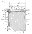
- FIG. 1A is a plan schematic view of a cellular sheet pile retaining system 100 a (“system 100 a ”) configured in accordance with an embodiment of the disclosure.
- the illustrated system 100 a includes multiple cell sheet pile structures 102 (identified individually as a first through third cell structures 102 a - 102 c ).
- Each cell structure 102 is formed from multiple interconnected sheet piles. More specifically, each cell structure 102 includes an exposed sheet face wall 104 extending between corresponding unconnected sheet tail walls 106 (identified individually as first through fourth tail walls 106 a - 106 d ). Adjacent cell structures 102 accordingly share a single tail wall 106 .
- FIG. 1A is a plan schematic view of a cellular sheet pile retaining system 100 a (“system 100 a ”) configured in accordance with an embodiment of the disclosure.
- the illustrated system 100 a includes multiple cell sheet pile structures 102 (identified individually as a first through third cell structures 102 a - 102 c ).
- the system 100 a includes multiple interconnected U-shaped cell structures 102 .
- the face walls 104 and tail walls 106 of each cell structure 102 are at least partially embedded in soil, and the tail walls 106 act as anchors for the corresponding face walls 104 .
- the face walls 104 are exposed to an exterior environment 101 , such as water.
- the face walls 104 and tail walls 106 can be interconnected and/or include integral soil anchors as described in U.S. Pat. No. 6,715,964 to William Dennis Nottingham, entitled “Earth Retaining System Such as a Sheet Pile Wall with Integral Soil Anchors,” filed Jul. 30, 2001; U.S. Pat. No.
- portions of the individual tail walls 106 can be embedded in the soil (e.g., in a direction into the plane of FIG. 1A ) at a greater or lesser depth than that of the corresponding face walls 104 .
- portions of the individual tail walls 106 can have a greater or lesser length (e.g., in the direction extending into the soil) than the corresponding face walls 104 .
- FIGS. 1B-1E are a series of plan schematic views of cellular sheet pile retaining systems with unconnected tail walls configured in accordance with further embodiments of the disclosure.
- the systems illustrated in FIGS. 1B-1E include several features that are generally similar in structure and function to the corresponding features of the system 100 a shown in FIG. 1A .
- the system 100 b illustrated in FIG. 1B includes cell structures 102 (identified individually as first through third cell structures 102 a - 102 c ) having face walls 104 extending between corresponding unconnected tail walls 106 (identified individually as first through fourth tail walls 106 a - 106 d ).
- the embodiments shown in FIGS. 1B-1E illustrate several possible configurations of the tail walls. In the embodiment illustrated in FIG.
- tail walls 106 have curved portions to account for various obstructions or site conditions. More specifically, for example, a mid-segment of the first tail wall 106 a has a curved portion 103 . Moreover, the second and third tail walls 106 b , 106 c each includes a bifurcated end including a first end portion 105 a curved away from or otherwise diverging from a second end portion 105 b . In addition the fourth tail wall 106 d has a single curved or non-linear end portion 107 . In other embodiments, the tail walls 106 can include other portions having other shapes or extending in other suitable directions to accommodate site conditions. In still further embodiments, the tail wall 106 d can be staggered up or down.
- the system 100 c illustrated in FIG. 1C includes cell structures 102 (identified individually as first through fifth cell structures 102 a - 102 e ) having face walls 104 extending between corresponding tail walls 106 .
- the third cell structure 102 c is curved to span or otherwise form a corner in the system 100 c .
- the third cell structure 102 c includes corresponding first and second tail walls 106 a that are curved away from one another so as not to intersect one another at an interior portion of the third cell structure 102 c .
- the tail walls 106 of a corresponding corner cell structure 102 can be shortened so as to not intersect one another.
- the tails walls 106 of a corner cell structure can intersect one another or any other corresponding tail wall.
- the illustrated system 100 d also includes multiple cell structures 102 (identified individually as first through fourth cell structures 102 a - 102 d ) having face walls 104 extending between corresponding tail walls 106 (identified individually as first through fifth tail walls 106 a - 106 e ).
- the tail walls 106 extend varying lengths away from the corresponding face walls 104 .
- the tail walls 106 of varying length can accordingly account for various site conditions, seismic conditions, etc.
- the illustrated system 100 e also includes multiple back-to-back or opposing cell structures 102 (identified individually as first through fifth cell structures 102 a - 102 e opposite corresponding sixth through tenth cell structures 102 f - 102 j ).
- First tail walls 106 a extending from the corresponding first through fifth cell structures 102 a - 102 e and are positioned adjacent to second tail walls 106 b extending from the corresponding sixth through tenth cell structures 102 f - 102 j .
- the back-to-back system 100 e shown in FIG. 1E can accordingly provide an economical alternative to closed cell systems, which can be more difficult and expensive to construct.
- embodiments of the present disclosure are not limited to the configurations shown in FIGS. 1A-1E .
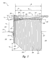
- FIG. 2 is a side cross-sectional view taken substantially along lines 2 - 2 of FIG. 1A illustrating several additional features of the system 100 a .
- the face wall 104 includes a series of interconnected face wall sheets or piles 213 that are partially embedded in soil 216 .
- the face wall piles 213 form an exposed surface 210 of the face wall 104 that faces an exterior environment 212 (e.g., water, shoreline, beach, river, valley, etc.).
- the exterior environment 212 can have a lower exterior level or surface 214 (e.g., ground, sea floor, river bed, valley floor, etc.).
- the tail wall 106 includes a series of interconnected tail wall sheets or piles 215 extending away from the face wall 104 .
- the individual tail wall piles 215 are at least partially embedded in the soil 216 and at least partially covered with backfill material 218 .
- the backfill material 218 can include at least a first backfill 220 (e.g., granular fill) covered by a second backfill 222 (e.g., surfacing and/or grading fill).
- utility or fuel lines and the like can be buried in the second backfill 222 and/or the first backfill 220 . In this manner, these lines can be protected from freezing and also be readily accessible for repair, leakage clean-up, replacement, etc.
- the face wall piles 213 and the tail wall piles 215 can be made from various materials including, for example, steel, aluminum, vinyl, plastic, wood, concrete, fiberglass, metallic and non-metallic alloys, and any other suitable materials.
- the tail wall 106 can include an anchor 237 spaced apart from the face wall 104 .
- the anchor can be configured to increase the pull-out resistance of the face wall 104 .
- the anchor 237 can be a tie-back anchor or dead weight that is operably coupled to the tail wall 106 .
- the anchor 237 can be integrally formed with the tail wall 106 .
- the anchor 237 can be integrally formed with the final tail wall pile 215 in the tail wall 106 . In other embodiments, however, the anchor 237 can be attached to the tail wall 106 (e.g., by welding, via a cable or rod, etc.).
- the tail wall 106 is embedded in the soil 216 at a depth that is deeper than that of the face wall 104 . Moreover, at least some of the tail wall piles 215 are longer than the face wall piles 213 (i.e., in the axial direction of these piles). More specifically, the tail wall 106 includes a first group G 1 of tail wall piles 215 and a second group of tail wall piles G 2 . In the illustrated embodiment, the first group G 1 includes 8 tail wall piles 215 , and the second group G 2 includes 31 tail wall piles 215 . In other embodiments, however, the first group G 1 and the second group G 2 can include greater than or less than 8 and 31 tail wall piles 215 , respectively.
- the face wall piles 213 and the tail wall piles 215 of the first group G 1 have a first length
- the tail wall piles 215 of the second group G 2 have a second length that is greater than the first length.
- the first length can be approximately 69 feet and the second length can be approximately 77 feet. In other embodiments, however, the first and second lengths can be greater than or less than 69 feet and 77 feet, respectively, depending, for example, on the conditions and environment where the system 100 a is constructed.
- the first group G 1 of tail wall piles 215 forms an upper staggered or stepped portion 224 of the tail wall 106 extending from a first upper surface 226 of the face wall 104 to a second upper surface 228 of the tail wall 106 .
- the tail wall 106 also includes a lower staggered or stepped portion 225 extending from a first lower surface 234 of the face wall 104 to a second lower surface 236 of the tail wall 106 .
- the individual tail wall piles 215 in the first group G 1 can be staggered from each other by a height of approximately 6-18 inches, or approximately 12 inches. In other embodiments, however, these piles can be staggered by a height less than 6 inches or greater than 18 inches.
- the tail wall 106 Several more features of the tail wall 106 are described with reference to a tail wall elevation 230 at the second upper surface 228 of the tail wall 106 .
- the first upper surface 226 is at a first height H 1 from the tail wall elevation 230
- an exterior surface 232 of the backfill 218 is at a second height H 2 from the tail wall elevation 230 .
- the lower exterior level 214 of the exterior environment 212 is at a third height H 3 below the tail wall elevation 230 .
- the first bottom surface 234 of the face wall 104 is at a fourth height H 4 from a second bottom surface 236 of the tail wall 106 .
- the first height H 1 can be approximately 10 feet
- the second height H 2 can be approximately 9 feet
- the third height H 3 can be approximately 30 feet
- the fourth height H 4 can be approximately 18 feet. In other embodiments, however, these heights can be greater than or less than these values to allow staggering tail walls both up and down.
- upper portions 227 of several of the initial tail wall piles 215 of the second group G 2 can be cut-off or otherwise removed at the elevation of the second upper surface 228 of, as shown by broken lines.
- the upper portions 227 can be removed because the tail wall piles 215 may be available only in certain predetermined lengths.
- removing these portions of the tail wall piles 215 allows the second upper surface 228 to be generally flat while the lowered staggered portion 225 of the tail wall 106 continues to extend deeper into the soil 216 .
- the first staggered portion 224 of the tail wall 106 extends away from the face wall 104 by a shorter distance than that of the second staggered portion 224 of the tail wall 106 .
- the staggered portion of the tail wall 106 allows the second group G 2 of tail wall piles 215 to be embedded in the soil 216 at a greater depth than the face wall 104 .
- the tail wall piles 215 of the second group G 2 which are longer in the longitudinal direction than the face wall piles 213 , contribute to the extended depth of the second bottom surface 236 of the tail wall 106 with reference to the first bottom surface 234 of the face wall 104 .
- the second bottom surface 236 of the tail wall 106 can be approximately 18 feet below the first bottom surface 234 of the face wall 104 .
- the second bottom surface 234 of the tail wall 106 can be approximately 78 feet from the first upper surface 226 of the face wall 104 . In other embodiments, however, these distances can be greater or less than these values.
- tail wall 106 provides several advantages over conventional retaining walls.
- the illustrated tail wall 106 provides an increased pull-out resistance of the face wall 104 , which accordingly yields a higher ultimate tension.
- This configuration also improves the stability of the system 100 a while also advantageously allowing the tail wall 106 to have a shorter distance D extending away from the face wall 104 compared to conventional retaining wall systems.
- the deeper tail wall 106 with longer tail wall piles 215 can reduce the distance D of the tail wall 106 extending away from the face wall 104 .
- tail wall piles 215 can also anchor the tail wall 106 into denser or stiffer soil below the soil failure zone as described below with reference to FIG. 5 .
- the illustrated tail wall 106 can also reduce the cost of the system 100 a because fewer tail wall 106 materials are required due to the reduced distance D of the tail wall 106 .
- FIG. 3 is a cross-sectional side view of a system 300 configured in accordance with another embodiment of the disclosure.
- the illustrated system 300 includes several features that are generally similar in structure and function to the corresponding features of the systems described above with reference to FIGS. 1A-2 .
- the system 300 includes a cell structure 302 with multiple tail wall sheet piles 315 forming a tail wall 306 , and multiple face wall piles 313 forming a face wall 304 .
- the tail wall 306 includes a first group G 1 , a second group G 2 , and a third group G 3 of the tail wall piles 315 .
- FIG. 3 is a cross-sectional side view of a system 300 configured in accordance with another embodiment of the disclosure.
- the illustrated system 300 includes several features that are generally similar in structure and function to the corresponding features of the systems described above with reference to FIGS. 1A-2 .
- the system 300 includes a cell structure 302 with multiple tail wall sheet piles 315 forming a tail wall 306
- the first group G 1 includes 8 tail wall piles 315
- the second group G 2 includes 2 tail wall piles 315
- the third group G 3 includes 27 tail wall piles 315 .
- the first group G 1 , the second group G 2 , and the third group G 3 can include greater than or less than 8, 2, and 27 tail wall piles 315 , respectively.
- the face wall piles 313 and tail wall piles 315 in the first group G 1 have a first length
- the tail wall piles 315 in the second group G 2 have a second length
- the tail wall piles 315 in the third group G 3 have a third length.
- the first length can be approximately 69 feet
- the second length can be approximately 77 feet
- the third length can be approximately 80 feet. In other embodiments, however, the first, second, and third lengths can be greater than or less than these values.
- upper portions 327 of several of the initial tail wall piles 315 of the second group G 2 and third group G 3 can be cut-off or otherwise removed at the elevation of the second upper surface 328 of, as shown by broken lines similar to the system 100 a described above with reference to FIG. 2 .
- FIG. 4 is a cross-sectional side view of a system 400 configured in accordance with yet another embodiment of the disclosure and particularly suited for expansion of a tail wall at a later date.
- the system 400 illustrated in FIG. 4 includes several features that are generally similar in structure and function to the corresponding features of the systems described above with reference to FIGS. 1A-3 .
- the system 400 includes a cell structure 402 with a tail wall 406 extending away from a face wall 404 .
- the tail wall 406 includes multiple interconnected tail wall sheet piles 415
- the face wall 404 includes multiple interconnected face wall sheet piles 413 .
- the tail wall 406 includes a first group G 1 and a second group G 2 of the tail wall sheet piles 415 .
- the tail wall sheet piles 415 in the first group G 1 represent tail wall sheet piles 415 that have been installed in the system.
- the second group G 2 of tail wall sheet piles 415 have been added at later time after the initial and completed installation of the first group G 1 of the tail wall sheet piles 415 .
- the system 400 illustrated in FIG. 4 is particularly suited for situations where additional support from the tail wall 406 may be needed after the initial installation of the tail wall 406 .
- the second group G 2 of tail wall sheet piles 415 can be added to the tail wall 406 to extend the tail wall 406 and provide additional anchor support without removing the entire wall system 400 or otherwise rebuilding the system 400 .
- the second group G 2 of tail wall sheet piles 415 can also provide additional pull-out support where the system 400 may be required to support additional loads or loads that are larger than initially anticipated.
- FIG. 5 is a cross-sectional side view of a system 500 configured in accordance with yet another embodiment of the disclosure.
- the system 500 includes several features that are generally similar in structure and function to the corresponding features of the systems described above with reference to FIGS. 1A-4 .
- the system 500 includes a cell structure 502 with a tail wall 506 extending away from a face wall 504 .
- the tail wall 506 includes multiple interconnected tail wall sheet piles 515
- the face wall 504 includes multiple interconnected face wall sheet piles 513 .
- the tail wall sheet piles 515 and the face wall sheet piles 513 are at least partially embedded in soil 516 with sections having varying or different densities.
- the soil includes a first section 517 positioned above and adjacent to a second section 519 .
- the first section 517 has a first density
- the second section 519 has a second density greater than the first density.
- the soil 516 also includes a global stability plane 529 , as well as a sliding block failure plane 531 .
- the sliding block failure plane 531 illustrates how the second section 519 can provide the required lateral resistance to prevent failure of the system 500 where soils above this level (e.g., the first section 517 ) are too soft to provide the required stability.
- the face wall sheet piles 513 extend at least partially through the first section 517 .
- the face wall sheet piles 513 do not, however, extend into the denser section 519 of the soil 516 or beyond the sliding block failure plane 531 .
- the tail wall sheet piles 515 extend through the first section 517 and at least partially into the second section 519 beyond the sliding block failure plane 531 . In this manner, the tail wall sheet piles 515 provide sufficient retaining support for the face wall 504 even when the less dense first section 517 would be unsuitable for retaining the face wall 504 .
- the system 500 can be installed in soil 516 having more than two different densities.
- the face wall sheet piles 513 do not extend into the second section 519 in the illustrated embodiment, in other embodiments the face wall sheet piles 513 can extend into at least a portion of the second section 519 and beyond the sliding block failure plane 531 .
- FIG. 6 is a cross-sectional side view of a system 600 configured in accordance with yet another embodiment of the disclosure.
- the system 600 includes several features that are generally similar in structure and function to the corresponding features of the systems described above with reference to FIGS. 1A-5 .
- the system 600 includes a cell structure 602 with a tail wall 606 extending away from a face wall 604 .
- the tail wall 606 includes multiple interconnected tail wall sheet piles 615
- the face wall 604 includes multiple interconnected face wall sheet piles 613 .
- the system 600 can also include a backfill material 618 at least partially disposed around the tail wall sheet piles 615 .
- the tail wall sheet piles 615 and the face wall sheet piles 613 extend at least partially through a first soil section 616 without extending into a denser second soil section 621 .
- the second soil section 621 can be a very dense soil, such as rock or bedrock.
- the tail wall sheet piles 615 can have a staggered pattern aligned with the profile of the second soil section 621 and extending away from the face wall 604 .
- the staggered pattern of the embodiment shown in FIG. 6 shows the lower end portions of the tail wall sheet piles 615 stepped or staggered upwardly with each successive tail wall sheet pile 615 having a progressively shorter length
- the tail wall sheet piles 615 can be staggered in the opposite direction (e.g., sloping downwardly with each successive tail wall sheet pile 615 having a progressively longer length).
- the upper end portions of the tail wall sheet piles 615 form a generally flat or even upper surface 632 aligned with an upper surface of the face wall 604
- the upper surface 632 of the tail wall can be higher or lower than the upper surface of the face wall.
Landscapes
- Engineering & Computer Science (AREA)
- Structural Engineering (AREA)
- Life Sciences & Earth Sciences (AREA)
- General Life Sciences & Earth Sciences (AREA)
- Mining & Mineral Resources (AREA)
- Paleontology (AREA)
- Civil Engineering (AREA)
- General Engineering & Computer Science (AREA)
- Bulkheads Adapted To Foundation Construction (AREA)
Abstract
Embodiments of the disclosure are directed to cellular sheet pile retaining wall systems with unconnected tail walls, and associated methods of use and manufacture. In one embodiment, a retaining system includes a face wall having a plurality of interconnected face wall sheet piles. The individual face wall sheet piles have a first length and extend a first depth into soil, and the face wall sheet piles form an exterior surface facing an exterior environment. The system also includes a tail wall including a plurality of interconnected tail wall sheet piles extending from the face wall away from the exterior environment. The individual tail wall sheet piles have a second length greater than the first length, and the individual tail sheet wall piles extend a second depth into the soil that is greater than the first depth.
Description
The present application claims priority to U.S. Provisional Patent Application No. 61/241,838, titled “OPEN CELL SHEET PILE RETAINING WALLS AND ASSOCIATED METHODS OF USE AND MANUFACTURE”, filed Sep. 11, 2009, which is incorporated herein by reference in its entirety.
The following disclosure relates generally to soil retaining systems, and more specifically to cellular sheet pile retaining systems with unconnected sheet pile tail walls, and associated structures and methods.
Marine related bulkheads constructed along the coast of Alaska experience some of the most severe environmental conditions known, including high waves and wave scour, earthquakes, ice, high tide variations, high phreatic water levels, weak soils, exposed or near-surface bedrock, heavy live loads, and difficult construction conditions. The need for low-cost, high load capacity docks and structures that allow field adaptation to changing field conditions has resulted in a development of various sheet pile retaining structures.
Flat steel sheet piles have been used in simple structures featuring primarily tension or membrane action. Foundation designs of cellular cofferdams are discussed in detail in the text by Joseph E. Bowles, Foundation Analysis and Design (1977) herein incorporated in its entirety by reference. One configuration, a closed cell flat sheet pile structure, had been successfully used for many years for a wide variety of structures including cofferdams and docks. The most common use for flat sheet piles has been in closed cellular bulkhead structures of various geometrical arrangements. Another configuration includes a diaphragm closed cell structure. By closing the cell structure, the entire structure acts as a deadman anchor in the retaining system to provide additional retaining support. However, positive structural aspects of these closed cell structures are often offset by high construction costs. Several factors have contributed to higher costs, including, for example: multiple templates required for construction alignment; close tolerances; difficulty with driving through obstacles and holding tolerance; backfilling operations using buckets or conveyors; and difficulty compacting the backfill.
Another sheet pile retaining form has been the tied back wall masterpile system with flat sheet piles acting as a curved tension face. Tieback anchors with deadmen are connected to the curved tension face to provide lateral retaining strength. This configuration allows a higher load to be retained with fewer sheet piles used as the anchors and the sheets work in concert to retain the earth load. However, tied back sheet pile walls often require deep toe embedment for lateral strength, and if that toe embedment is removed for any number of reasons, wall failure will result. This configuration further requires excavation for placement of the soil anchors, or an expensive and time consuming drilling operation to install the soil anchors, at the appropriate depth to integrate them with the sheet pile wall. Additionally, tied back walls are at risk in environments where waves overtop the wall and result in scour. Scour undermines the base of the bulkhead and the needed toe support resulting in failure of the bulkhead. The tied back walls are subject to failure during seismic events at the tied back connection to the wall and failure due to corrosion either at the tied back connection to the wall or the wall itself where corrosion of the exposed wall at the air/water interface occurs.
Several embodiments of the disclosure are described below with reference to soil retaining systems, and more particularly, with reference to cellular sheet pile retaining wall systems with unconnected tail walls, and associated methods of use. In one embodiment, for example, a retaining system includes a face wall having a plurality of interconnected face wall sheet piles. The individual face wall sheet piles have a first length and extend a first depth into soil. The face wall sheet piles form an exterior surface facing an exterior environment, such as water, shoreline, beach, river, valley, etc. The system also includes a first tail wall including a plurality of interconnected first tail wall sheet piles extending from the face wall away from the exterior environment. The individual first tail wall sheet piles anchor the face wall and have a second length greater than the first length. Moreover, the individual first tail wall sheet piles extend a second depth into the soil that is greater than the first depth. The system further includes a second tail wall spaced apart from and unconnected to the first tail wall. The second tail wall has a plurality of interconnected second tail wall sheet piles extending from the face wall away from the exterior environment to further anchor the face wall. The individual second tail wall sheet piles have a third length approximately equal to or greater than the second length. Moreover, individual second tail wall sheet piles extend a third depth into the soil, the third depth being equal to or greater than the second depth.
Specific details are identified in the following description with reference to FIGS. 1A-6 to provide a thorough understanding of various embodiments of the disclosure. Other details describing well-known structures or processes often associated with sheet pile retailing walls, however, are not described below to avoid unnecessarily obscuring the description of the various embodiments of the disclosure. Moreover, although the following disclosure sets forth several embodiments of different aspects of the invention, other embodiments can have different configurations and/or different components and structures than those described in this section. In addition, further embodiments of the disclosure may be practiced without several of the details described below, while still other embodiments of the disclosure may be practiced with additional details and/or features.
Many of the details, dimensions, angles and/or other portions shown in the Figures are merely illustrative of particular embodiments of the disclosure. Accordingly, other embodiments can have other details, dimensions, angles and/or portions without departing from the spirit or scope of the present disclosure. In addition, further embodiments of the disclosure may be practiced without several of the details described below, while still other embodiments of the disclosure may be practiced with additional details and/or features.
As described below in detail with reference to FIGS. 2-6 , portions of the individual tail walls 106, such as individual piles, can be embedded in the soil (e.g., in a direction into the plane of FIG. 1A ) at a greater or lesser depth than that of the corresponding face walls 104. Moreover, portions of the individual tail walls 106, such as individual piles, can have a greater or lesser length (e.g., in the direction extending into the soil) than the corresponding face walls 104.
Referring next to FIG. 1C , the system 100 c illustrated in FIG. 1C includes cell structures 102 (identified individually as first through fifth cell structures 102 a-102 e) having face walls 104 extending between corresponding tail walls 106. In the embodiment illustrated in FIG. 1C , however, the third cell structure 102 c is curved to span or otherwise form a corner in the system 100 c. As such, the third cell structure 102 c includes corresponding first and second tail walls 106 a that are curved away from one another so as not to intersect one another at an interior portion of the third cell structure 102 c. In other embodiments, however, the tail walls 106 of a corresponding corner cell structure 102 can be shortened so as to not intersect one another. In still further embodiments, the tails walls 106 of a corner cell structure can intersect one another or any other corresponding tail wall.
In FIG. 1D , the illustrated system 100 d also includes multiple cell structures 102 (identified individually as first through fourth cell structures 102 a-102 d) having face walls 104 extending between corresponding tail walls 106 (identified individually as first through fifth tail walls 106 a-106 e). In the embodiment illustrated in FIG. 1D , however, the tail walls 106 extend varying lengths away from the corresponding face walls 104. The tail walls 106 of varying length can accordingly account for various site conditions, seismic conditions, etc.
In FIG. 1E , the illustrated system 100 e also includes multiple back-to-back or opposing cell structures 102 (identified individually as first through fifth cell structures 102 a-102 e opposite corresponding sixth through tenth cell structures 102 f-102 j). First tail walls 106 a extending from the corresponding first through fifth cell structures 102 a-102 e and are positioned adjacent to second tail walls 106 b extending from the corresponding sixth through tenth cell structures 102 f-102 j. The back-to-back system 100 e shown in FIG. 1E can accordingly provide an economical alternative to closed cell systems, which can be more difficult and expensive to construct. As one of ordinary skill in the art will appreciate, embodiments of the present disclosure are not limited to the configurations shown in FIGS. 1A-1E .
The face wall piles 213 and the tail wall piles 215 can be made from various materials including, for example, steel, aluminum, vinyl, plastic, wood, concrete, fiberglass, metallic and non-metallic alloys, and any other suitable materials. In certain embodiments, the tail wall 106 can include an anchor 237 spaced apart from the face wall 104. The anchor can be configured to increase the pull-out resistance of the face wall 104. For example, the anchor 237 can be a tie-back anchor or dead weight that is operably coupled to the tail wall 106. In certain embodiments, the anchor 237 can be integrally formed with the tail wall 106. For example, the anchor 237 can be integrally formed with the final tail wall pile 215 in the tail wall 106. In other embodiments, however, the anchor 237 can be attached to the tail wall 106 (e.g., by welding, via a cable or rod, etc.).
According to one feature of the illustrated embodiment, the tail wall 106 is embedded in the soil 216 at a depth that is deeper than that of the face wall 104. Moreover, at least some of the tail wall piles 215 are longer than the face wall piles 213 (i.e., in the axial direction of these piles). More specifically, the tail wall 106 includes a first group G1 of tail wall piles 215 and a second group of tail wall piles G2. In the illustrated embodiment, the first group G1 includes 8 tail wall piles 215, and the second group G2 includes 31 tail wall piles 215. In other embodiments, however, the first group G1 and the second group G2 can include greater than or less than 8 and 31 tail wall piles 215, respectively. The face wall piles 213 and the tail wall piles 215 of the first group G1 have a first length, and the tail wall piles 215 of the second group G2 have a second length that is greater than the first length. In one embodiment, for example, the first length can be approximately 69 feet and the second length can be approximately 77 feet. In other embodiments, however, the first and second lengths can be greater than or less than 69 feet and 77 feet, respectively, depending, for example, on the conditions and environment where the system 100 a is constructed.
As also shown in the illustrated embodiment, the first group G1 of tail wall piles 215 forms an upper staggered or stepped portion 224 of the tail wall 106 extending from a first upper surface 226 of the face wall 104 to a second upper surface 228 of the tail wall 106. The tail wall 106 also includes a lower staggered or stepped portion 225 extending from a first lower surface 234 of the face wall 104 to a second lower surface 236 of the tail wall 106. In one embodiment, for example, the individual tail wall piles 215 in the first group G1 can be staggered from each other by a height of approximately 6-18 inches, or approximately 12 inches. In other embodiments, however, these piles can be staggered by a height less than 6 inches or greater than 18 inches.
Several more features of the tail wall 106 are described with reference to a tail wall elevation 230 at the second upper surface 228 of the tail wall 106. For example, the first upper surface 226 is at a first height H1 from the tail wall elevation 230, and an exterior surface 232 of the backfill 218 is at a second height H2 from the tail wall elevation 230. Moreover, the lower exterior level 214 of the exterior environment 212 is at a third height H3 below the tail wall elevation 230. In addition, the first bottom surface 234 of the face wall 104 is at a fourth height H4 from a second bottom surface 236 of the tail wall 106. In certain embodiments, the first height H1 can be approximately 10 feet, the second height H2 can be approximately 9 feet, the third height H3 can be approximately 30 feet, and the fourth height H4 can be approximately 18 feet. In other embodiments, however, these heights can be greater than or less than these values to allow staggering tail walls both up and down.
As also shown in FIG. 2 , at the second upper surface 228 of the tail wall 106 following the transition from the first group G1 to the second group G2 of tail wall piles 215, upper portions 227 of several of the initial tail wall piles 215 of the second group G2 can be cut-off or otherwise removed at the elevation of the second upper surface 228 of, as shown by broken lines. The upper portions 227 can be removed because the tail wall piles 215 may be available only in certain predetermined lengths. Moreover, removing these portions of the tail wall piles 215 allows the second upper surface 228 to be generally flat while the lowered staggered portion 225 of the tail wall 106 continues to extend deeper into the soil 216. In addition, the first staggered portion 224 of the tail wall 106 extends away from the face wall 104 by a shorter distance than that of the second staggered portion 224 of the tail wall 106.
The staggered portion of the tail wall 106 allows the second group G2 of tail wall piles 215 to be embedded in the soil 216 at a greater depth than the face wall 104. Moreover, the tail wall piles 215 of the second group G2, which are longer in the longitudinal direction than the face wall piles 213, contribute to the extended depth of the second bottom surface 236 of the tail wall 106 with reference to the first bottom surface 234 of the face wall 104. In certain embodiments, for example, the second bottom surface 236 of the tail wall 106 can be approximately 18 feet below the first bottom surface 234 of the face wall 104. Accordingly, the second bottom surface 234 of the tail wall 106 can be approximately 78 feet from the first upper surface 226 of the face wall 104. In other embodiments, however, these distances can be greater or less than these values.
These features of the tail wall 106 (e.g., that the tail wall 106 that is embedded deeper than the face wall 104, and the longer tail wall piles 215 of the second group G2) provide several advantages over conventional retaining walls. For example, the illustrated tail wall 106 provides an increased pull-out resistance of the face wall 104, which accordingly yields a higher ultimate tension. This configuration also improves the stability of the system 100 a while also advantageously allowing the tail wall 106 to have a shorter distance D extending away from the face wall 104 compared to conventional retaining wall systems. For example, in areas with limited property rights or in soft soils, the deeper tail wall 106 with longer tail wall piles 215 can reduce the distance D of the tail wall 106 extending away from the face wall 104. These deeper tail wall piles 215 can also anchor the tail wall 106 into denser or stiffer soil below the soil failure zone as described below with reference to FIG. 5 . The illustrated tail wall 106 can also reduce the cost of the system 100 a because fewer tail wall 106 materials are required due to the reduced distance D of the tail wall 106.
As also shown in the embodiment illustrated in FIG. 3 , at an upper surface 328 of the tail wall 306 following the transition from the first group G1 to the second group G2, and from the second group G2 to the third group G3 of the tail wall piles 315, upper portions 327 of several of the initial tail wall piles 315 of the second group G2 and third group G3 can be cut-off or otherwise removed at the elevation of the second upper surface 328 of, as shown by broken lines similar to the system 100 a described above with reference to FIG. 2 .
The system 400 illustrated in FIG. 4 is particularly suited for situations where additional support from the tail wall 406 may be needed after the initial installation of the tail wall 406. For example, in situations with poor fill material surrounding the first group G1 of tail wall sheet piles 415, the second group G2 of tail wall sheet piles 415 can be added to the tail wall 406 to extend the tail wall 406 and provide additional anchor support without removing the entire wall system 400 or otherwise rebuilding the system 400. The second group G2 of tail wall sheet piles 415 can also provide additional pull-out support where the system 400 may be required to support additional loads or loads that are larger than initially anticipated.
Although the staggered pattern of the embodiment shown in FIG. 6 shows the lower end portions of the tail wall sheet piles 615 stepped or staggered upwardly with each successive tail wall sheet pile 615 having a progressively shorter length, in other embodiments the tail wall sheet piles 615 can be staggered in the opposite direction (e.g., sloping downwardly with each successive tail wall sheet pile 615 having a progressively longer length). Moreover, although the upper end portions of the tail wall sheet piles 615 form a generally flat or even upper surface 632 aligned with an upper surface of the face wall 604, in other embodiments the upper surface 632 of the tail wall can be higher or lower than the upper surface of the face wall.
From the foregoing, it will be appreciated that specific embodiments have been described herein for purposes of illustration, but that various modifications may be made without deviating from the spirit and scope of the disclosure. Certain aspects and/or features described in the context of particular embodiments may be combined or eliminated in other embodiments. Further, although advantages associated with certain embodiments have been described in the context of those embodiments, other embodiments may also exhibit such advantages, and not all embodiments need necessarily exhibit such advantages to fall within the scope of the disclosure. The following examples provide further embodiments of the disclosure.
Claims (19)
1. A retaining system at least partially embedded in soil, the retaining system comprising:
a face wall including a plurality of interconnected face wall sheet piles, wherein individual face wall sheet piles have a first length and individual face wall sheet piles extend a first depth into the soil, and wherein the face wall sheet piles form an exterior surface facing an exterior environment;
a first tail wall including a plurality of interconnected first tail wall sheet piles connected with and extending from the face wall away from the exterior environment, wherein individual first tail wall sheet piles have a second length greater than the first length and individual first tail wall sheet piles extend a second depth into the soil that is greater than the first depth; and
a second tail wall connected with the first tail wall and including a plurality of interconnected second tail wall sheet piles extending from the first tail wall away from the exterior environment, wherein individual second tail wall sheet piles have a third length approximately equal to or greater than the second length and individual second tail wall sheet piles extend a third depth into the soil, wherein the third depth is equal to or greater than the second depth,
wherein the second depth of individual sheet piles of the first tail wall increases uniformly in a staggered fashion from the face wall toward the second tail wall, and wherein the second length of individual sheet piles of the first tail wall increases for the sheet piles that are adjacent to the second tail wall.
2. The system of claim 1 wherein the first tail wall further comprises:
at least one first tail wall sheet piles having a fourth length greater than the second length; and
at least one first tail wall sheet piles having a fifth length greater than the fourth length.
3. The system of claim 1 wherein the first tail wall further comprises:
at least one first tail wall sheet piles extending a fourth depth into the soil, wherein the fourth depth is greater than the second depth; and
at least one first tail wall sheet piles extending a fifth depth into the soil, wherein the fifth depth is greater than the fourth depth.
4. The system of claim 1 wherein the first tail wall sheet piles in the staggered portion all have the same length.
5. The system of claim 1 wherein the first depth extends at least partially through a first portion of the soil, and wherein the second depth extends through the first portion and at least partially through second portion of the soil, wherein the first portion of the soil has a first density and the second portion of the soil has a second density, the second density being greater than the first density.
6. The system of claim 1 wherein the face wall and the first and second tail walls have a generally U-shaped configuration.
7. The system of claim 1 wherein the exterior environment comprises water.
8. The system of claim 1 wherein the first tail wall includes an end portion opposite the face wall, and wherein the end portion is configured to be attached to additional first tail wall sheet piles at a later time after an initial installation of the first tail wall has been completed.
9. The system of claim 1 wherein the first tail wall includes a first section of consecutive first tail wall sheet piles and a second section of consecutive first tail wall sheet piles, and further wherein:
end portions of the first tail wall sheet piles in the first section are staggered at a varying depth in the soil; and
end portions of the first tail wall sheet piles in the second section are positioned at a generally uniform depth in the soil.
10. The system of claim 9 wherein at least one of the tail wall sheet piles in the second section of the first tail wall has a fourth length greater than the second length of the tail wall sheet piles in the first section of the first tail wall.
11. A retaining system at least partially embedded in soil, the retaining system comprising:
a face wall including a plurality of interconnected face wall sheet piles forming an exterior surface, wherein individual face wall sheet piles extend a first depth into the soil; and
a tail wall extending from the face wall away from the exterior surface, wherein the tail wall includes:
a first plurality of interconnected tail wall sheet piles, wherein at least one of the tail wall sheet piles of the first plurality extends a second depth into the soil, wherein the second depth is greater than the first depth; and
a second plurality of interconnected tail wall sheet piles, wherein at least one of the tail wall sheet piles of the second plurality extends a third depth into the soil, wherein the third depth is greater than the second depth
wherein the second depth of individual sheet piles of the first plurality of interconnected tail wall sheet piles increases uniformly in a staggered fashion from the face wall toward the second plurality of interconnected tail wall sheet piles, and wherein the second length of interconnected sheet piles of the first tail wall increases for the sheet piles that are adjacent to the second tail wall.
12. The system of claim 11 wherein the individual face wall sheet piles have a first length, and wherein at least one of the tail wall sheet piles of the first plurality of interconnected tail wall sheet piles has a second length that is greater than the first length.
13. The system of claim 11 wherein:
the soil includes a first section having a first density, and a second section below the first section, the second section having a second density that is greater than the first density; and
the individual face wall sheet piles extend only through at least a portion of a first section of the soil, and the tail wall sheet piles of the first plurality of interconnected sheet piles extend through the first section and also through at least a portion of a second section of the soil, wherein the first section of the soil has a first density and the second section of the soil has a second density, and wherein the second density is greater than the first density.
14. A retaining system at least partially embedded in soil, the retaining system comprising:
a face wall including a plurality of interconnected first sheet piles forming an exterior surface, wherein individual first sheet piles have a first length and are at least partially embedded in the soil; and
a tail wall extending from the face wall away from the exterior surface, wherein the tail wall includes:
a plurality of interconnected second sheet piles at least partially embedded in the soil, wherein at least one of the second sheet piles has a second length that is greater than the first length, and
a plurality of interconnected third sheet piles at least partially embedded in the soil, wherein at least one of the third sheet piles has a third length that is greater than the second length,
wherein the interconnected second sheet piles extend to a distance into the soil that increases in a uniformly staggered fashion from the face wall toward the plurality of interconnected third sheet piles, and wherein the second length of individual sheet piles of the second sheet piles increases for the sheet piles that are adjacent to the third sheet piles.
15. The system of claim 14 wherein:
the first sheet piles are embedded a first distance into the soil.
16. The system of claim 14 wherein:
the first sheet piles extend only partially through a first section of the soil; and
the second sheet piles extend through the first section and at least partially through a second section of the soil, wherein the first section of the soil has a first density and the second section of the soil has a second density, and wherein the second density is greater than the first density.
17. A method of constructing a retaining wall system, the method comprising:
partially embedding a plurality of interconnected face wall piles in soil at a first depth, wherein the individual face wall piles have a first length;
partially embedding a plurality of interconnected first tail wall piles in the soil at a second depth greater than the first depth, wherein the first tail wall piles extend in a direction away from the face wall piles; and
partially embedding a plurality of interconnected second tail wall piles in the soil at a second depth greater than the first depth, wherein the second tail wall piles are adjacent to the first tail wall piles, wherein the second tail wall piles extend in a direction away from the face wall piles, and wherein at least one of the second tail wall piles has a third length greater than the second length,
wherein the second depth of individual sheet piles of the first tail wall increases uniformly in a staggered fashion from the face wall toward the second tail wall, and wherein the second length of individual sheet piles of the first tail wall increases for sheet piles that are adjacent to the second tail wall.
18. The method of claim 17 wherein:
partially embedding the face wall piles in the soil comprises partially embedding the face wall piles in a first section of the soil having a first density; and
partially embedding the tail wall piles of the first plurality of interconnected sheet piles in the soil comprises embedding the tail wall piles in the first section and partially embedding the tail wall piles in a second section of the soil, the second section having a second density that is greater than the first density.
19. The method of claim 17 wherein after completed installation of the tail wall piles of the first plurality of interconnected sheet piles and after a predetermined amount of time, the method further comprises connecting one or more additional tail wall piles of the second plurality of interconnected sheet piles to an end tail wall pile spaced apart and opposite from the face wall piles.
Priority Applications (2)
| Application Number | Priority Date | Filing Date | Title |
|---|---|---|---|
| US12/879,997 US10024017B2 (en) | 2009-09-11 | 2010-09-10 | Cellular sheet pile retaining systems with unconnected tail walls, and associated methods of use |
| US16/033,554 US11149395B2 (en) | 2009-09-11 | 2018-07-12 | Cellular sheet pile retaining systems with unconnected tail walls, and associated methods of use |
Applications Claiming Priority (2)
| Application Number | Priority Date | Filing Date | Title |
|---|---|---|---|
| US24183809P | 2009-09-11 | 2009-09-11 | |
| US12/879,997 US10024017B2 (en) | 2009-09-11 | 2010-09-10 | Cellular sheet pile retaining systems with unconnected tail walls, and associated methods of use |
Related Child Applications (1)
| Application Number | Title | Priority Date | Filing Date |
|---|---|---|---|
| US16/033,554 Continuation US11149395B2 (en) | 2009-09-11 | 2018-07-12 | Cellular sheet pile retaining systems with unconnected tail walls, and associated methods of use |
Publications (2)
| Publication Number | Publication Date |
|---|---|
| US20110064527A1 US20110064527A1 (en) | 2011-03-17 |
| US10024017B2 true US10024017B2 (en) | 2018-07-17 |
Family
ID=43728735
Family Applications (2)
| Application Number | Title | Priority Date | Filing Date |
|---|---|---|---|
| US12/879,997 Active US10024017B2 (en) | 2009-09-11 | 2010-09-10 | Cellular sheet pile retaining systems with unconnected tail walls, and associated methods of use |
| US16/033,554 Active US11149395B2 (en) | 2009-09-11 | 2018-07-12 | Cellular sheet pile retaining systems with unconnected tail walls, and associated methods of use |
Family Applications After (1)
| Application Number | Title | Priority Date | Filing Date |
|---|---|---|---|
| US16/033,554 Active US11149395B2 (en) | 2009-09-11 | 2018-07-12 | Cellular sheet pile retaining systems with unconnected tail walls, and associated methods of use |
Country Status (2)
| Country | Link |
|---|---|
| US (2) | US10024017B2 (en) |
| CA (1) | CA2714679C (en) |
Families Citing this family (6)
| Publication number | Priority date | Publication date | Assignee | Title |
|---|---|---|---|---|
| CA2714679C (en) * | 2009-09-11 | 2017-11-07 | Pnd Engineers, Inc. | Cellular sheet pile retaining systems with unconnected tail walls, and associated methods of use |
| US10145076B2 (en) * | 2016-08-12 | 2018-12-04 | Pnd Engineers, Inc. | Sheet pile bulkhead systems and methods |
| US9945091B1 (en) | 2016-10-13 | 2018-04-17 | Subsurface, Inc. | Portable cofferdam system |
| US10094088B1 (en) | 2017-10-31 | 2018-10-09 | Earth, Inc. | Sheet pile retaining wall system |
| US10407861B2 (en) * | 2017-10-31 | 2019-09-10 | Earth Inc. | Sheet pile retaining wall system |
| CN110847197B (en) * | 2019-11-23 | 2021-01-08 | 中铁二十局集团有限公司 | Comprehensive treatment method for loess tunnel entrance section crossing landslide body |
Citations (79)
| Publication number | Priority date | Publication date | Assignee | Title |
|---|---|---|---|---|
| US370108A (en) * | 1887-09-20 | Sheet-piling | ||
| US400155A (en) * | 1889-03-26 | Territory | ||
| US717135A (en) * | 1902-05-01 | 1902-12-30 | Newton S Taylor | Metal-sheet piling and wall structure. |
| US912661A (en) | 1908-04-07 | 1909-02-16 | Slater T Fiero | Interlocking sheet-metal piling. |
| US923110A (en) | 1908-06-06 | 1909-05-25 | Lackawanna Steel Co | Interlocking sheet-piling. |
| US968450A (en) | 1910-03-28 | 1910-08-23 | Cloud C Conkling | Metal sheet-piling. |
| US969343A (en) | 1909-04-16 | 1910-09-06 | Lackawanna Steel Co | Composite piling. |
| US975665A (en) * | 1910-04-25 | 1910-11-15 | Julius R Wemlinger | Shoring. |
| US1005514A (en) | 1911-02-20 | 1911-10-10 | Lackawanna Steel Co | Steel sheet-piling. |
| US1012124A (en) | 1911-04-22 | 1911-12-19 | Lackawanna Steel Co | Metal sheet-piling. |
| US1032109A (en) | 1910-11-01 | 1912-07-09 | Lackawanna Steel Co | Junction member for steel sheet-piling. |
| US1071985A (en) | 1912-02-23 | 1913-09-02 | Lackawanna Steel Co | Caisson construction. |
| US1277847A (en) * | 1917-07-11 | 1918-09-03 | Elias Cahn | Coffer-dam. |
| US1341949A (en) | 1918-05-13 | 1920-06-01 | Troye Einar | Sheet-piling |
| US1437044A (en) | 1919-08-07 | 1922-11-28 | Great Lakes Dredge & Dock Comp | Cofferdam construction |
| US1806967A (en) | 1931-05-26 | Egbert s | ||
| US1834744A (en) | 1929-06-24 | 1931-12-01 | Schroeder Kurt | Symmetrical piling made of channel-iron sections |
| US1896259A (en) | 1929-05-21 | 1933-02-07 | George E Thackray | Sheet piling |
| US1907135A (en) * | 1931-04-20 | 1933-05-02 | Said Wemlinger | Sea wall |
| US1942163A (en) * | 1933-03-24 | 1934-01-02 | Mario Di Zoppola & Company Inc | Bulkhead and sea-wall structure |
| US1943800A (en) * | 1932-01-23 | 1934-01-16 | George D Morrison | Sectional wall and method of erecting it |
| US1951292A (en) | 1929-04-18 | 1934-03-13 | James E Cahill | Assembled pile |
| US1951293A (en) | 1929-06-10 | 1934-03-13 | James E Cahill | Cofferdam |
| US2004188A (en) | 1934-01-05 | 1935-06-11 | Dortmund Hoerder Huettenver Ag | Reverse angle interlock piling |
| US2018446A (en) * | 1933-09-09 | 1935-10-22 | Jensen Johannes | Sheet piling |
| US2057947A (en) | 1934-05-14 | 1936-10-20 | August H Hausler | Method of driving sheet piling |
| US2074906A (en) | 1934-05-14 | 1937-03-23 | August H Hausler | Guide for use in driving sheet piling |
| US2128012A (en) * | 1937-04-07 | 1938-08-23 | James J O'rourke | Beach protecting barrier |
| US2128428A (en) | 1936-08-18 | 1938-08-30 | Jr Thomas E Murray | Sheet piling |
| US2184974A (en) * | 1939-04-22 | 1939-12-26 | William P Witherow | Retaining wall |
| US2909901A (en) | 1954-11-16 | 1959-10-27 | De Long Corp | Tank footing members for a combined barge and working platform assembly |
| US2968931A (en) * | 1959-03-04 | 1961-01-24 | Leonard J Mcgrath | Aligning fixture for assembling sheet piling |
| US3059436A (en) | 1956-03-19 | 1962-10-23 | Jr George F Hermann | Piling |
| US3302412A (en) | 1964-06-29 | 1967-02-07 | William A Hunsucker | Interlocking sheet piles and method of installation |
| US3613382A (en) * | 1969-08-06 | 1971-10-19 | West Construction Enterprises | Sea wall construction |
| US3751930A (en) | 1971-12-27 | 1973-08-14 | Texaco Inc | Articulated marine structure with prepositioned anchoring piles |
| US3754403A (en) | 1972-02-09 | 1973-08-28 | Texaco Inc | Offshore marine structure embodying anchor pile means |
| US3797258A (en) | 1972-07-12 | 1974-03-19 | S Dubuisson | Shim take-up ring for pile connection |
| US3802205A (en) * | 1969-08-06 | 1974-04-09 | Seawall Enterprises Inc | Sea wall construction |
| US3822557A (en) | 1972-09-29 | 1974-07-09 | L Frederick | Jet sheet and circular pile with water hammer assist |
| US3959938A (en) * | 1973-07-02 | 1976-06-01 | John Zachariassen | Wall system of corrugated sections |
| US3971224A (en) * | 1973-11-26 | 1976-07-27 | Erwin Elkuch | Method for erecting a pile wall adapted to take compressive forces and a pile wall produced by the method |
| US3993396A (en) | 1976-01-12 | 1976-11-23 | E. I. Du Pont De Nemours And Company | Connector block |
| US4050254A (en) * | 1975-08-13 | 1977-09-27 | International Engineering Company, Inc. | Modular structures, retaining wall system, and method of construction |
| JPS55136328A (en) * | 1979-04-10 | 1980-10-24 | Kubota Ltd | Constructing method for wall of steel-pipe sheet pile |
| US4369004A (en) * | 1980-10-01 | 1983-01-18 | Schnabel Foundation Company | Earth retaining method and structure |
| US4419030A (en) * | 1981-09-14 | 1983-12-06 | Burkemper Methods, Inc. | Apparatus for and method of constructing a sheet piling shoring structure |
| US4479742A (en) | 1982-02-03 | 1984-10-30 | Gulf Canada Limited | Mobile bottom-founded caisson for arctic operations |
| US4486125A (en) | 1982-12-30 | 1984-12-04 | Mobil Oil Corporation | Modular arctic structures system |
| JPS6062326A (en) * | 1983-09-13 | 1985-04-10 | Yoshihiko Kawai | Formation work of cut-off wall and sheet pile therefor |
| US4511288A (en) | 1981-11-30 | 1985-04-16 | Global Marine Inc. | Modular island drilling system |
| US4579481A (en) | 1983-04-29 | 1986-04-01 | Standard Oil Company | Mobile offshore drilling structure for the arctic |
| US4596495A (en) | 1985-02-22 | 1986-06-24 | Standard Oil Company | Spud bushing system for mobile offshore arctic drilling structure |
| US4618286A (en) | 1984-02-16 | 1986-10-21 | Fluor-Doris Incorporated | Composite platform for petroleum workings in polar seas |
| US4647257A (en) | 1985-02-22 | 1987-03-03 | Robishaw Engineering, Inc. | Method and apparatus for constructing elevated structures |
| US4685838A (en) | 1983-06-29 | 1987-08-11 | Valerian Curt | Retaining wall |
| US4790690A (en) * | 1986-02-05 | 1988-12-13 | Henri Vidal | Stabilised earth structures |
| US4890959A (en) | 1985-07-22 | 1990-01-02 | Robishaw Alces P | Transportation and construction method |
| JPH0393917A (en) * | 1989-09-05 | 1991-04-18 | Wakachiku Kensetsu Kk | Steel sheet pile underwater build-up method and nipper for steel sheet pile |
| US5213447A (en) | 1990-10-31 | 1993-05-25 | Srock Bryan J | Interconnecting water platform |
| US5292207A (en) | 1993-02-15 | 1994-03-08 | Allen Bradford Resources, Inc. | Ice crush resistant caisson for arctic offshore oil well drilling |
| US5437520A (en) * | 1991-11-08 | 1995-08-01 | University Of Waterloo | Sealing system for in-ground barrier |
| US5505563A (en) * | 1989-08-21 | 1996-04-09 | Curt; Valerian | Cellular structures for sustaining walls |
| US5520487A (en) | 1993-07-07 | 1996-05-28 | Arbed S.A. | Waterproof clutches for sheet piles |
| US6135675A (en) * | 1997-12-19 | 2000-10-24 | Northstar Vinyl Products Llc | Sheetpile system including full plastic exterior |
| US6234720B1 (en) * | 1996-12-02 | 2001-05-22 | Foundation Technologies, Inc. | Reduced skin friction sheet pile |
| US6371699B1 (en) * | 1997-10-16 | 2002-04-16 | Durisol Inc. | Anchored retaining wall system |
| US20020054791A1 (en) * | 2000-07-28 | 2002-05-09 | William Dennis Nottingham | Earth retaining system such as a sheet pile wall with integral soil anchors |
| US6443659B1 (en) | 1998-11-23 | 2002-09-03 | Philip J. Patout | Movable self-elevating artificial work island with modular hull |
| US20040206516A1 (en) * | 2002-05-31 | 2004-10-21 | Benedict Charles E. | Permanent and semi-permanent groyne structures and method for shoreline and land mass reclamation |
| US7033118B2 (en) * | 2004-06-23 | 2006-04-25 | Hilfiker Pipe Company | Compressible welded wire retaining wall and rock face for earthen formations |
| US7086811B2 (en) * | 1999-12-29 | 2006-08-08 | Cgl Systems Llc | Pre-stressed modular retaining wall system and method |
| US7107225B1 (en) | 1999-08-17 | 2006-09-12 | Mcclung Iii Guy L | Business system |
| US20070163186A1 (en) | 2003-04-08 | 2007-07-19 | Baugh Benton F | Arctic platform |
| EP1813727A2 (en) * | 2006-01-25 | 2007-08-01 | Van de Coterlet, Jan | Method for producing a sheet pile wall and sheet pile plank therefor |
| US20100143044A1 (en) | 2002-05-08 | 2010-06-10 | Kadaster Ali G | Method and System for Building Modular Structures from Which Oil and Gas Wells are Drilled |
| US20100290843A1 (en) * | 2009-05-12 | 2010-11-18 | Cmi Limited Company | System and method for installing sheet piles |
| US20110064527A1 (en) * | 2009-09-11 | 2011-03-17 | Pnd Engineers, Inc. | Cellular sheet pile retaining systems with unconnected tail walls, and associated methods of use |
| US7958835B2 (en) | 2007-01-01 | 2011-06-14 | Nagan Srinivasan | Offshore floating production, storage, and off-loading vessel for use in ice-covered and clear water applications |
Family Cites Families (4)
| Publication number | Priority date | Publication date | Assignee | Title |
|---|---|---|---|---|
| US1067489A (en) | 1913-02-24 | 1913-07-15 | James W Sederquist | Interlocking sheet-piling. |
| US3024112A (en) * | 1958-07-10 | 1962-03-06 | Gen Foods Corp | Production of biscuits |
| US5333971A (en) | 1992-11-03 | 1994-08-02 | Lewis John A | Interlocking bulkhead |
| US8444348B2 (en) | 2009-06-30 | 2013-05-21 | Pnd Engineers, Inc. | Modular offshore platforms and associated methods of use and manufacture |
-
2010
- 2010-09-10 CA CA2714679A patent/CA2714679C/en active Active
- 2010-09-10 US US12/879,997 patent/US10024017B2/en active Active
-
2018
- 2018-07-12 US US16/033,554 patent/US11149395B2/en active Active
Patent Citations (85)
| Publication number | Priority date | Publication date | Assignee | Title |
|---|---|---|---|---|
| US1806967A (en) | 1931-05-26 | Egbert s | ||
| US400155A (en) * | 1889-03-26 | Territory | ||
| US370108A (en) * | 1887-09-20 | Sheet-piling | ||
| US717135A (en) * | 1902-05-01 | 1902-12-30 | Newton S Taylor | Metal-sheet piling and wall structure. |
| US912661A (en) | 1908-04-07 | 1909-02-16 | Slater T Fiero | Interlocking sheet-metal piling. |
| US923110A (en) | 1908-06-06 | 1909-05-25 | Lackawanna Steel Co | Interlocking sheet-piling. |
| US969343A (en) | 1909-04-16 | 1910-09-06 | Lackawanna Steel Co | Composite piling. |
| US968450A (en) | 1910-03-28 | 1910-08-23 | Cloud C Conkling | Metal sheet-piling. |
| US975665A (en) * | 1910-04-25 | 1910-11-15 | Julius R Wemlinger | Shoring. |
| US1032109A (en) | 1910-11-01 | 1912-07-09 | Lackawanna Steel Co | Junction member for steel sheet-piling. |
| US1005514A (en) | 1911-02-20 | 1911-10-10 | Lackawanna Steel Co | Steel sheet-piling. |
| US1012124A (en) | 1911-04-22 | 1911-12-19 | Lackawanna Steel Co | Metal sheet-piling. |
| US1071985A (en) | 1912-02-23 | 1913-09-02 | Lackawanna Steel Co | Caisson construction. |
| US1277847A (en) * | 1917-07-11 | 1918-09-03 | Elias Cahn | Coffer-dam. |
| US1341949A (en) | 1918-05-13 | 1920-06-01 | Troye Einar | Sheet-piling |
| US1437044A (en) | 1919-08-07 | 1922-11-28 | Great Lakes Dredge & Dock Comp | Cofferdam construction |
| US1951292A (en) | 1929-04-18 | 1934-03-13 | James E Cahill | Assembled pile |
| US1896259A (en) | 1929-05-21 | 1933-02-07 | George E Thackray | Sheet piling |
| US1951293A (en) | 1929-06-10 | 1934-03-13 | James E Cahill | Cofferdam |
| US1834744A (en) | 1929-06-24 | 1931-12-01 | Schroeder Kurt | Symmetrical piling made of channel-iron sections |
| US1907135A (en) * | 1931-04-20 | 1933-05-02 | Said Wemlinger | Sea wall |
| US1943800A (en) * | 1932-01-23 | 1934-01-16 | George D Morrison | Sectional wall and method of erecting it |
| US1942163A (en) * | 1933-03-24 | 1934-01-02 | Mario Di Zoppola & Company Inc | Bulkhead and sea-wall structure |
| US2018446A (en) * | 1933-09-09 | 1935-10-22 | Jensen Johannes | Sheet piling |
| US2004188A (en) | 1934-01-05 | 1935-06-11 | Dortmund Hoerder Huettenver Ag | Reverse angle interlock piling |
| US2057947A (en) | 1934-05-14 | 1936-10-20 | August H Hausler | Method of driving sheet piling |
| US2074906A (en) | 1934-05-14 | 1937-03-23 | August H Hausler | Guide for use in driving sheet piling |
| US2128428A (en) | 1936-08-18 | 1938-08-30 | Jr Thomas E Murray | Sheet piling |
| US2128012A (en) * | 1937-04-07 | 1938-08-23 | James J O'rourke | Beach protecting barrier |
| US2184974A (en) * | 1939-04-22 | 1939-12-26 | William P Witherow | Retaining wall |
| US2909901A (en) | 1954-11-16 | 1959-10-27 | De Long Corp | Tank footing members for a combined barge and working platform assembly |
| US3059436A (en) | 1956-03-19 | 1962-10-23 | Jr George F Hermann | Piling |
| US2968931A (en) * | 1959-03-04 | 1961-01-24 | Leonard J Mcgrath | Aligning fixture for assembling sheet piling |
| US3302412A (en) | 1964-06-29 | 1967-02-07 | William A Hunsucker | Interlocking sheet piles and method of installation |
| US3613382A (en) * | 1969-08-06 | 1971-10-19 | West Construction Enterprises | Sea wall construction |
| US3802205A (en) * | 1969-08-06 | 1974-04-09 | Seawall Enterprises Inc | Sea wall construction |
| US3751930A (en) | 1971-12-27 | 1973-08-14 | Texaco Inc | Articulated marine structure with prepositioned anchoring piles |
| US3754403A (en) | 1972-02-09 | 1973-08-28 | Texaco Inc | Offshore marine structure embodying anchor pile means |
| US3797258A (en) | 1972-07-12 | 1974-03-19 | S Dubuisson | Shim take-up ring for pile connection |
| US3822557A (en) | 1972-09-29 | 1974-07-09 | L Frederick | Jet sheet and circular pile with water hammer assist |
| US3959938A (en) * | 1973-07-02 | 1976-06-01 | John Zachariassen | Wall system of corrugated sections |
| US3971224A (en) * | 1973-11-26 | 1976-07-27 | Erwin Elkuch | Method for erecting a pile wall adapted to take compressive forces and a pile wall produced by the method |
| US4050254A (en) * | 1975-08-13 | 1977-09-27 | International Engineering Company, Inc. | Modular structures, retaining wall system, and method of construction |
| US3993396A (en) | 1976-01-12 | 1976-11-23 | E. I. Du Pont De Nemours And Company | Connector block |
| JPS55136328A (en) * | 1979-04-10 | 1980-10-24 | Kubota Ltd | Constructing method for wall of steel-pipe sheet pile |
| US4369004A (en) * | 1980-10-01 | 1983-01-18 | Schnabel Foundation Company | Earth retaining method and structure |
| US4419030A (en) * | 1981-09-14 | 1983-12-06 | Burkemper Methods, Inc. | Apparatus for and method of constructing a sheet piling shoring structure |
| US4511288A (en) | 1981-11-30 | 1985-04-16 | Global Marine Inc. | Modular island drilling system |
| US4479742A (en) | 1982-02-03 | 1984-10-30 | Gulf Canada Limited | Mobile bottom-founded caisson for arctic operations |
| US4486125A (en) | 1982-12-30 | 1984-12-04 | Mobil Oil Corporation | Modular arctic structures system |
| US4579481A (en) | 1983-04-29 | 1986-04-01 | Standard Oil Company | Mobile offshore drilling structure for the arctic |
| US4685838A (en) | 1983-06-29 | 1987-08-11 | Valerian Curt | Retaining wall |
| JPS6062326A (en) * | 1983-09-13 | 1985-04-10 | Yoshihiko Kawai | Formation work of cut-off wall and sheet pile therefor |
| US4618286A (en) | 1984-02-16 | 1986-10-21 | Fluor-Doris Incorporated | Composite platform for petroleum workings in polar seas |
| US4647257A (en) | 1985-02-22 | 1987-03-03 | Robishaw Engineering, Inc. | Method and apparatus for constructing elevated structures |
| US4596495A (en) | 1985-02-22 | 1986-06-24 | Standard Oil Company | Spud bushing system for mobile offshore arctic drilling structure |
| US4890959A (en) | 1985-07-22 | 1990-01-02 | Robishaw Alces P | Transportation and construction method |
| US4790690A (en) * | 1986-02-05 | 1988-12-13 | Henri Vidal | Stabilised earth structures |
| US5505563A (en) * | 1989-08-21 | 1996-04-09 | Curt; Valerian | Cellular structures for sustaining walls |
| JPH0393917A (en) * | 1989-09-05 | 1991-04-18 | Wakachiku Kensetsu Kk | Steel sheet pile underwater build-up method and nipper for steel sheet pile |
| US5213447A (en) | 1990-10-31 | 1993-05-25 | Srock Bryan J | Interconnecting water platform |
| US5437520A (en) * | 1991-11-08 | 1995-08-01 | University Of Waterloo | Sealing system for in-ground barrier |
| US5292207A (en) | 1993-02-15 | 1994-03-08 | Allen Bradford Resources, Inc. | Ice crush resistant caisson for arctic offshore oil well drilling |
| US5520487A (en) | 1993-07-07 | 1996-05-28 | Arbed S.A. | Waterproof clutches for sheet piles |
| US6234720B1 (en) * | 1996-12-02 | 2001-05-22 | Foundation Technologies, Inc. | Reduced skin friction sheet pile |
| US6371699B1 (en) * | 1997-10-16 | 2002-04-16 | Durisol Inc. | Anchored retaining wall system |
| US6135675A (en) * | 1997-12-19 | 2000-10-24 | Northstar Vinyl Products Llc | Sheetpile system including full plastic exterior |
| US6443659B1 (en) | 1998-11-23 | 2002-09-03 | Philip J. Patout | Movable self-elevating artificial work island with modular hull |
| US6499914B1 (en) | 1998-11-23 | 2002-12-31 | Philip J. Patout | Movable self-elevating artificial work island with modular hull |
| US7107225B1 (en) | 1999-08-17 | 2006-09-12 | Mcclung Iii Guy L | Business system |
| US7086811B2 (en) * | 1999-12-29 | 2006-08-08 | Cgl Systems Llc | Pre-stressed modular retaining wall system and method |
| US20090232607A1 (en) * | 2000-07-28 | 2009-09-17 | Peratrovich, Nottingham & Drage, Inc. | Earth retaining system such as a sheet pile wall with integral soil anchors |
| US7488140B2 (en) | 2000-07-28 | 2009-02-10 | Peratrovich, Nottingham & Drage, Inc. | Earth retaining system such as a sheet pile wall with integral soil anchors |
| US7018141B2 (en) | 2000-07-28 | 2006-03-28 | Peratrovich, Nottingham & Drage, Inc. | Earth retaining system such as a sheet pile wall with integral soil anchors |
| US6715964B2 (en) * | 2000-07-28 | 2004-04-06 | Peratrovich, Nottingham & Drage, Inc. | Earth retaining system such as a sheet pile wall with integral soil anchors |
| US20020054791A1 (en) * | 2000-07-28 | 2002-05-09 | William Dennis Nottingham | Earth retaining system such as a sheet pile wall with integral soil anchors |
| US20100143044A1 (en) | 2002-05-08 | 2010-06-10 | Kadaster Ali G | Method and System for Building Modular Structures from Which Oil and Gas Wells are Drilled |
| US20040206516A1 (en) * | 2002-05-31 | 2004-10-21 | Benedict Charles E. | Permanent and semi-permanent groyne structures and method for shoreline and land mass reclamation |
| US20070163186A1 (en) | 2003-04-08 | 2007-07-19 | Baugh Benton F | Arctic platform |
| US20080286053A1 (en) | 2003-04-08 | 2008-11-20 | Baugh Benton F | Arctic platform |
| US7033118B2 (en) * | 2004-06-23 | 2006-04-25 | Hilfiker Pipe Company | Compressible welded wire retaining wall and rock face for earthen formations |
| EP1813727A2 (en) * | 2006-01-25 | 2007-08-01 | Van de Coterlet, Jan | Method for producing a sheet pile wall and sheet pile plank therefor |
| US7958835B2 (en) | 2007-01-01 | 2011-06-14 | Nagan Srinivasan | Offshore floating production, storage, and off-loading vessel for use in ice-covered and clear water applications |
| US20100290843A1 (en) * | 2009-05-12 | 2010-11-18 | Cmi Limited Company | System and method for installing sheet piles |
| US20110064527A1 (en) * | 2009-09-11 | 2011-03-17 | Pnd Engineers, Inc. | Cellular sheet pile retaining systems with unconnected tail walls, and associated methods of use |
Also Published As
| Publication number | Publication date |
|---|---|
| US11149395B2 (en) | 2021-10-19 |
| US20110064527A1 (en) | 2011-03-17 |
| US20190100893A1 (en) | 2019-04-04 |
| CA2714679A1 (en) | 2011-03-11 |
| CA2714679C (en) | 2017-11-07 |
Similar Documents
| Publication | Publication Date | Title |
|---|---|---|
| US11149395B2 (en) | Cellular sheet pile retaining systems with unconnected tail walls, and associated methods of use | |
| US10287741B2 (en) | Earth retaining system such as a sheet pile wall with integral soil anchors | |
| CN104452829A (en) | Piled raft foundation anti-floating structure and construction method | |
| KR101077949B1 (en) | Block for reinforcement and construction method | |
| JP3789127B1 (en) | Seismic structure | |
| CN211200426U (en) | Anti-sliding supporting and retaining structure for miniature steel pipe pile retaining wall | |
| CN212506313U (en) | Combined foundation pit supporting structure | |
| WO2009082672A1 (en) | Sand and soil internal reinforcement system | |
| JP7149919B2 (en) | Improvement structure and improvement method of existing wharf | |
| EP3068948B1 (en) | Method and apparatus for stabilising a dike | |
| US3677113A (en) | Method and apparatus for forming a foundation-leg assembly for an offshore platform | |
| CN109518717A (en) | A kind of Retaining Wall and construction method | |
| CN103821073B (en) | A kind of small bridge and its construction method | |
| JPH04228714A (en) | Water area construction using member to be driven into water bottom ground | |
| CN211395213U (en) | Road shoulder sheet wall large deformation reinforcing structure | |
| CN219948521U (en) | Permanently-combined dock wall structure | |
| CN216919973U (en) | Floating type bridge deep water shock insulation foundation capable of being reset | |
| CN215289929U (en) | Gravity type retaining wall and miniature pile combined supporting structure | |
| EP4198203A1 (en) | Process of anchoring a floating platform on a rocky seabed | |
| KR20150105891A (en) | The underground facilities for offshore airfield of semi land reclamation type | |
| CN115710910A (en) | Groove-bin high-slope deep foundation pit supporting method | |
| AU2014202480B2 (en) | Sea defence | |
| Dismuke | Retaining structures and excavations | |
| Cuevas et al. | Underpinning Building in Deposits of Lacustrine Origin | |
| JPH11269842A (en) | Marine earth wall structure |
Legal Events
| Date | Code | Title | Description |
|---|---|---|---|
| AS | Assignment |
Owner name: PND ENGINEERS, INC., ALASKA Free format text: ASSIGNMENT OF ASSIGNORS INTEREST;ASSIGNORS:NOTTINGHAM, WILLIAM D.;HARTLEY, MICHAEL;GUNDERSON, WILLIAM F.;SIGNING DATES FROM 20100918 TO 20101012;REEL/FRAME:025316/0890 |
|
| STCF | Information on status: patent grant |
Free format text: PATENTED CASE |
|
| MAFP | Maintenance fee payment |
Free format text: PAYMENT OF MAINTENANCE FEE, 4TH YR, SMALL ENTITY (ORIGINAL EVENT CODE: M2551); ENTITY STATUS OF PATENT OWNER: SMALL ENTITY Year of fee payment: 4 |