RU2735373C1 - Telemetric ultrasound device for diagnosing sensorineural hearing loss - Google Patents
Telemetric ultrasound device for diagnosing sensorineural hearing loss Download PDFInfo
- Publication number
- RU2735373C1 RU2735373C1 RU2019143353A RU2019143353A RU2735373C1 RU 2735373 C1 RU2735373 C1 RU 2735373C1 RU 2019143353 A RU2019143353 A RU 2019143353A RU 2019143353 A RU2019143353 A RU 2019143353A RU 2735373 C1 RU2735373 C1 RU 2735373C1
- Authority
- RU
- Russia
- Prior art keywords
- microprocessor
- ultrasonic
- output
- input
- power
- Prior art date
Links
Images
Classifications
-
- A—HUMAN NECESSITIES
- A61—MEDICAL OR VETERINARY SCIENCE; HYGIENE
- A61B—DIAGNOSIS; SURGERY; IDENTIFICATION
- A61B5/00—Measuring for diagnostic purposes; Identification of persons
- A61B5/12—Audiometering
- A61B5/121—Audiometering evaluating hearing capacity
- A61B5/125—Audiometering evaluating hearing capacity objective methods
-
- A—HUMAN NECESSITIES
- A61—MEDICAL OR VETERINARY SCIENCE; HYGIENE
- A61B—DIAGNOSIS; SURGERY; IDENTIFICATION
- A61B5/00—Measuring for diagnostic purposes; Identification of persons
- A61B5/12—Audiometering
- A61B5/128—Audiometering evaluating tinnitus
-
- A—HUMAN NECESSITIES
- A61—MEDICAL OR VETERINARY SCIENCE; HYGIENE
- A61B—DIAGNOSIS; SURGERY; IDENTIFICATION
- A61B8/00—Diagnosis using ultrasonic, sonic or infrasonic waves
-
- H—ELECTRICITY
- H04—ELECTRIC COMMUNICATION TECHNIQUE
- H04R—LOUDSPEAKERS, MICROPHONES, GRAMOPHONE PICK-UPS OR LIKE ACOUSTIC ELECTROMECHANICAL TRANSDUCERS; DEAF-AID SETS; PUBLIC ADDRESS SYSTEMS
- H04R25/00—Deaf-aid sets, i.e. electro-acoustic or electro-mechanical hearing aids; Electric tinnitus maskers providing an auditory perception
Landscapes
- Health & Medical Sciences (AREA)
- Life Sciences & Earth Sciences (AREA)
- Physics & Mathematics (AREA)
- Engineering & Computer Science (AREA)
- General Health & Medical Sciences (AREA)
- Audiology, Speech & Language Pathology (AREA)
- Animal Behavior & Ethology (AREA)
- Medical Informatics (AREA)
- Acoustics & Sound (AREA)
- Biophysics (AREA)
- Veterinary Medicine (AREA)
- Pathology (AREA)
- Public Health (AREA)
- Biomedical Technology (AREA)
- Heart & Thoracic Surgery (AREA)
- Surgery (AREA)
- Molecular Biology (AREA)
- Otolaryngology (AREA)
- Multimedia (AREA)
- Signal Processing (AREA)
- Radiology & Medical Imaging (AREA)
- Nuclear Medicine, Radiotherapy & Molecular Imaging (AREA)
- Neurosurgery (AREA)
- Ultra Sonic Daignosis Equipment (AREA)
Abstract
Description
Изобретение относится к области медицинской техники. Прибор для диагностики поражений слуха различных поражений слуха и может использоваться в больницах и клиниках, а также в научно-исследовательских медицинских учреждениях.The invention relates to the field of medical technology. A device for diagnosing hearing impairments of various hearing impairments and can be used in hospitals and clinics, as well as in research medical institutions.
Ультразвуковых тесты имеют существенное значение в дифференциальной диагностике различных поражений слуха: отосклероза, адгезивного среднего отита, болезни Меньера и хронического гнойного среднего отита, а также нейросенсорной тугоухости различной этиологии. Методика предусматривает измерения дифференциальных порогов восприятия пациентом ультразвуков через костную проводимость и сравнение их с дифференциальными порогами восприятия силы звуков обычно слышимого звукового диапазона частот.Ultrasound tests are essential in the differential diagnosis of various hearing lesions: otosclerosis, adhesive otitis media, Meniere's disease and chronic suppurative otitis media, as well as sensorineural hearing loss of various etiologies. The technique involves measuring the differential thresholds of perception by the patient of ultrasound through bone conduction and comparing them with the differential thresholds of perception of the strength of sounds of the usually audible sound frequency range.
Известен ультразвуковой прибор для диагностики поражений слуха (см. RU 2252698 кл. А61В 5/12, 27.05.2005), содержащий, генератор колебаний ультразвуковой частоты, усилитель с дискретно регулируемым коэффициентом усиления, соединенный с усилителем мощности, выход которого через датчик тока соединен с пьезоэлектрическим излучателем, преобразователь тока в напряжение, подсоединенный к выходу датчика тока, блок коммутации и панель управления с кнопками увеличения мощности излучения, уменьшения мощности излучения и изменения скорости регулирования мощности, а также цифровыми сегментными индикаторами Недостатком указанного ультразвукового прибора для диагностики поражений слуха является нестабильность мощности излучения при различной механической нагрузке на пьезоэлектрический излучатель, возникающей в результате различной силы прижатия излучателя. Другим недостатком указанного ультразвукового прибора для диагностики поражений слуха является недостаточная надежность, обусловленная большим количеством цифровых схем.Known ultrasonic device for the diagnosis of hearing damage (see RU 2252698 cl.
Наиболее близким к данному техническому решению является прибор для диагностики нейросенсорной тугоухости, содержащий генератор колебаний ультразвуковой частоты, полосовой фильтр, усилитель с дискретно регулируемым коэффициентом усиления, усилитель мощности, датчик тока и преобразователь тока в напряжение, а также блок коммутации, амплитудный детектор тока и амплитудный детектор напряжения, выходы которых подключены к входам блока коммутации, вход амплитудного детектора тока подключен к выходу преобразователя тока в напряжение, микропроцессор, подключенный к управляющему входу усилителя с дискретно регулируемым коэффициентом усиления, аналого-цифровой преобразователь, вход которого подключен к выходу блока коммутации, а выход - к микропроцессору, панель управления и пьезоэлектрический излучатель, (см. RU 2307587, кл. А61В 5/12, 10.10.2007).The closest to this technical solution is a device for the diagnosis of sensorineural hearing loss, containing an oscillator of ultrasonic frequency, a band-pass filter, an amplifier with discretely controlled gain, a power amplifier, a current sensor and a current-to-voltage converter, as well as a switching unit, an amplitude current detector and an amplitude a voltage detector, the outputs of which are connected to the inputs of the switching unit, the input of the amplitude current detector is connected to the output of the current-to-voltage converter, a microprocessor connected to the control input of an amplifier with discretely adjustable gain, an analog-to-digital converter, the input of which is connected to the output of the switching unit, and output - to the microprocessor, control panel and piezoelectric emitter, (see RU 2307587,
Недостатком указанного прибора является отсутствие системы автоматической настройки частоты генератора ультразвуковых сигналов на резонансную частоту ультразвукового излучателя, что может привести к большим погрешностям измерения в связи изменением параметров ультразвукового во времени или при замене излучателя.The disadvantage of this device is the absence of a system for automatic tuning of the frequency of the generator of ultrasonic signals to the resonant frequency of the ultrasonic emitter, which can lead to large measurement errors due to changes in the parameters of the ultrasonic in time or when replacing the emitter.
Другим недостатком указанного прибора является отсутствие возможности автоматизированного формирования протокола обследования пациента и невозможность использования прибора в системах телемедицины.Another disadvantage of this device is the lack of the possibility of automated generation of the patient examination protocol and the impossibility of using the device in telemedicine systems.
Указанный технический результат достигается тем, что телеметрический ультразвуковой прибор для диагностики нейросенсорной тугоухости, содержащий генератор колебаний ультразвуковой частоты, полосовой фильтр, усилитель с дискретно регулируемым коэффициентом усиления, вход которого подключен к полосовому фильтру, а выход соединен с входом усилителя мощности, выход которого через датчик тока соединен с пьезоэлектрическим излучателем, преобразователь тока в напряжение, подсоединенный к датчику тока, блок коммутации, панель управления с кнопками увеличения мощности излучения, уменьшения мощности излучения и изменения скорости регулирования мощности, а также цифровыми сегментными индикаторами, микропроцессор, первый и второй амплитудные детекторы и аналого-цифровой преобразователь, причем вход полосового фильтра подключен к генератору колебаний ультразвуковой частоты, первый выход микропроцессора подключен к управляющему входу усилителя с дискретно регулируемым коэффициентом усиления, второй выход микропроцессора подключен к цифровым сегментным индикаторам, к входам микропроцессора подсоединены кнопки увеличения мощности излучения, уменьшения мощности излучения и изменения скорости регулирования мощности, а также выход аналого-цифрового преобразователя, к входу которого подключен выход блока коммутации, к входам блока коммутации подсоединены выходы первого и второго амплитудных детекторов, вход первого амплитудного детектора подключен к выходу преобразователя тока в напряжение, а вход второго амплитудного детектор подключен к пьезоэлектрическому излучателю, содержит кнопку выбора места воздействия ультразвуком на голове пациента и кнопку фиксации порогового уровня восприятия ультразвукового сигнала, расположенные на панели управления и связанные с микропроцессором, компьютер, соединенный с микропроцессором и сетью Интернет, монитор и принтер, подключенные к компьютеру, генератор сигналов ультразвуковой частоты выполнен в виде генератора, управляемого напряжением, а управляющий вход ультразвукового генератора подключен к микропроцессору.The specified technical result is achieved by the fact that a telemetric ultrasonic device for the diagnosis of sensorineural hearing loss, containing a generator of ultrasonic frequency oscillations, a bandpass filter, an amplifier with discretely adjustable gain, the input of which is connected to a bandpass filter, and the output is connected to the input of the power amplifier, the output of which is through the sensor current is connected to a piezoelectric emitter, a current-to-voltage converter connected to a current sensor, a switching unit, a control panel with buttons for increasing the radiation power, decreasing the radiation power and changing the power regulation rate, as well as digital segment displays, a microprocessor, the first and second amplitude detectors and analog-to-digital converter, and the input of the bandpass filter is connected to the oscillator of ultrasonic frequency, the first output of the microprocessor is connected to the control input of the amplifier with discretely adjustable gain, the second the output of the microprocessor is connected to the digital segment displays, the buttons for increasing the radiation power, decreasing the radiation power and changing the rate of power regulation are connected to the inputs of the microprocessor, as well as the output of the analog-to-digital converter, to the input of which the output of the switching unit is connected, the outputs of the first and of the second amplitude detectors, the input of the first amplitude detector is connected to the output of the current-to-voltage converter, and the input of the second amplitude detector is connected to a piezoelectric emitter, contains a button for selecting the place of exposure to ultrasound on the patient's head and a button for fixing the threshold level of perception of an ultrasonic signal, located on the control panel and connected with a microprocessor, a computer connected to a microprocessor and the Internet, a monitor and a printer connected to a computer, an ultrasonic frequency signal generator is made in the form of a voltage controlled generator, and The input input of the ultrasonic generator is connected to the microprocessor.
Указанный технический результат достигается также тем, что что кнопка увеличения мощности излучения, кнопка уменьшения мощности излучения, кнопка изменения скорости регулирования мощности, кнопка выбора места воздействия ультразвуком на голове пациента и кнопка фиксации порогового уровня восприятия ультразвукового сигнала выполнены в виде виртуальных кнопок, отображаемых на экране монитора.The specified technical result is also achieved by the fact that the button for increasing the radiation power, the button for decreasing the radiation power, the button for changing the power control speed, the button for selecting the place of exposure to ultrasound on the patient's head and the button for fixing the threshold level of perception of the ultrasonic signal are made in the form of virtual buttons displayed on the screen monitor.
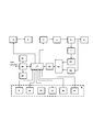
На фигуре представлена принципиальная схема телеметрического ультразвукового прибора для диагностики нейросенсорной тугоухости.The figure shows a schematic diagram of a telemetric ultrasound device for the diagnosis of sensorineural hearing loss.
На фигуре приведены следующие обозначения:The figure shows the following designations:
1 - генератор колебаний ультразвуковой частоты, управляемый напряжением;1 - voltage controlled oscillation generator of ultrasonic frequency;
2 - полосовой фильтр;2 - bandpass filter;
3 - усилитель с дискретно регулируемым коэффициентом усиления;3 - amplifier with discretely adjustable gain;
4 - усилитель мощности;4 - power amplifier;
5 - датчик тока;5 - current sensor;
6 - пьезоэлектрический излучатель;6 - piezoelectric emitter;
7 - преобразователь тока в напряжение;7 - current-to-voltage converter;
8 - панель управления;8 - control panel;
9 - кнопка увеличения мощности излучения;9 - button for increasing the radiation power;
10 - кнопка уменьшения мощности излучения;10 - button for decreasing radiation power;
11 - кнопка изменения скорости регулирования мощности;11 - button for changing the speed of power regulation;
12 - цифровые сегментные индикаторы;12 - digital segment displays;
13 - первый амплитудный детектор;13 - the first amplitude detector;
14 - второй амплитудный детектор;14 - second amplitude detector;
15- блок коммутации;15- switching unit;
16 - аналого-цифровой преобразователь;16 - analog-to-digital converter;
17 - микропроцессор;17 - microprocessor;
18 - кнопка выбора места воздействия ультразвуком на голове пациента;18 - button for selecting the site of ultrasound exposure on the patient's head;
19 - кнопка фиксации порогового уровня восприятия ультразвукового сигнала;19 - button for fixing the threshold level of ultrasonic signal perception;
20 - компьютер;20 - computer;
21 - монитор;21 - monitor;
22 - принтер.22 - printer.
Ультразвуковой прибор для диагностики поражений слуха содержит генератор колебаний ультразвуковой частоты 1, соединенный через полосовой фильтр 2 с усилителем 3 с дискретно регулируемым коэффициентом усиления, выход которого через усилитель мощности 4 и датчик тока 5 соединен с пьезоэлектрическим излучателем 6. К датчику тока 5 подсоединен преобразователь тока в напряжение 7. Прибор содержит панель управления 8 с кнопками увеличения мощности излучения 9, уменьшения мощности излучения 10, кнопкой изменения скорости регулирования мощности 11, кнопкой фиксации порогового уровня восприятия ультразвукового сигнала 18, цифровыми сегментными индикаторами 12, а также первый амплитудный детектор 13 и второй амплитудный детектор 14, подключенные соответственно к преобразователю тока в напряжение 7 и пьезоэлектрическому излучателю 6. Выходы указанных амплитудных детекторов через блок коммутации 15 подключены к аналого-цифровому преобразователю 16, выход которого подключен к микропроцессору 17. Порты микропроцессора 17 соединены с управляющим входом усилителя 3 с дискретно регулируемым коэффициентом усиления, с управляющим входом генератора ультразвуковых сигналов 1, управляемого напряжением, с кнопкой 9 увеличения мощности излучения, кнопкой 10 уменьшения мощности излучения мощности излучения, кнопкой 11 изменения скорости регулирования мощности, кнопкой 18 выбора места воздействия ультразвуком на голове пациента и кнопкой 19 фиксации порогового уровня восприятия ультразвукового сигнала, расположенными на панели управления 8. Микропроцессор 17 соединен с компьютером 20, соединенным с сетью интернет. К компьютеру подключены монитор 21 и принтер 22.An ultrasonic device for diagnosing hearing damage contains an oscillator of
Работа телеметрического ультразвукового прибора для диагностики нейросенсорной тугоухости осуществляется следующим образом.The operation of a telemetric ultrasound device for the diagnosis of sensorineural hearing loss is as follows.
При включении питания прибора процессор 17 в соответствии с программой вырабатывает сигнал изменения частоты генератора ультразвуковых колебаний 1 в заданных пределах. Для заданного ряда фиксированных частот производится измерение напряжения ультразвукового сигнала на пьезоэлектрическом излучателе 6 с помощью второго амплитудного детектора 14. Измеренные значения напряжений, соответствующих заданным частотам, через коммутатор 15 подаются на вход аналого-цифрового преобразователя 16 и после оцифровки поступают в микропроцессор 17. Микропроцессор в соответствии с программой определяет максимальное напряжение на пьезоэлектрическом излучателе 6, которое соответствует его резонансной частоте, и далее посредством подачи соответствующего напряжения на управляющий вход генератора ультразвуковых сигналов 1 устанавливает его рабочую частоту равной резонансной частоте пьезоэлектрического излучателя 6. Этим обеспечивается заданная точность измерения порогового уровня восприятия ультразвукового сигнала при изменении резонансной частоты излучателя во времени и нестабильности частоты генератора, а также замене излучателя.When the power is turned on, the
С выхода генератора 1 колебаний ультразвуковой частоты модулированный ультразвуковой сигнал поступает на вход полосового фильтра 2, который подавляет паразитные гармоники и комбинационные составляющие, возникающие при модуляции ультразвукового сигнала. С выхода полосового фильтра модулированный ультразвуковой сигнал поступает на вход усилителя с дискретно регулируемым коэффициентом усиления 3.From the output of the
С выхода усилителя с дискретно регулируемым коэффициентом усиления модулированный 3 ультразвуковой сигнал поступает на усилитель мощности 4, обеспечивающий необходимую мощность на пьезоэлектрическом излучателе 6, который преобразует электрический сигнал в механические колебания ультразвуковой частоты.From the output of the amplifier with discretely adjustable gain, the modulated
Между усилителем мощности 4 и пьезоэлектрическим излучателем 6 включен датчик тока 5. К нему подключен преобразователь тока в напряжение 7, на котором ток, проходящий через пьезоэлектрический излучатель, преобразуется в напряжение и поступает на первый амплитудный детектор 13. К пьезоэлектрическому излучателю 6 подключен второй амплитудный детектор 14. С выходов первого и второго амплитудных детекторов 13 и 14 напряжения через блок коммутации 15 поступают на аналого-цифровой преобразователь, где происходит их преобразование в цифровой код и передача на микропроцессор 17.A
Микропроцессор осуществляет программное управление усилителем с дискретно регулируемым коэффициентом усиления 3 по последовательному интерфейсу I2C, вычисление уровня мощности на излучателе путем измерения напряжений, пропорциональных уровню выходного напряжения и току излучателя, поступающих с соответствующих детекторов напряжения и тока. Таблица значений номинальных мощностей, соответствующих каждому уровню в диапазоне 0-30 дБ, хранится в микропроцессоре.The microprocessor performs software control of the amplifier with discretely
Вычисление текущей мощности на излучателе производится по следующей формуле:The calculation of the current power at the radiator is carried out according to the following formula:
![]()
![]()
где 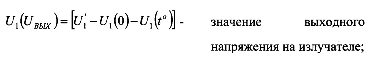
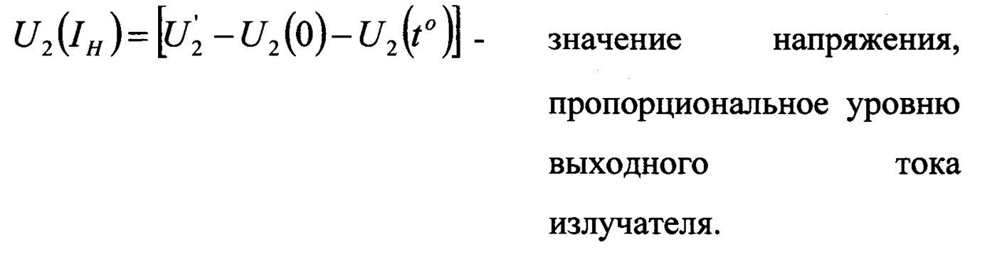
Здесь:Here:
![]()
![]()
U1(0) - начальное напряжение смещения первого амплитудного детектора 13 (UВЫХ) при отсутствии выходных ультразвуковых колебаний на излучателе (режим «ПАУЗА»), измеренных при ![]()
![]()
U1(to) - напряжение смещения первого амплитудного детектора 13 (UВЫХ) в режиме «ПАУЗА» во время работы;U 1 (t o ) - bias voltage of the first amplitude detector 13 (U OUT ) in the "PAUSE" mode during operation;
![]()
![]()
U2(0) - начальное напряжение смещения второго амплитудного детектора 14 (IH) при отсутствии выходных ультразвуковых колебаний на излучателе (режим «ПАУЗА»), измеренных при ![]()
![]()
U2(t°) - напряжение смещения второго амплитудного детектора 14 (IH) в режиме «ПАУЗА» во время работы;U 2 (t °) - bias voltage of the second amplitude detector 14 (I H ) in the "PAUSE" mode during operation;
K - коэффициент пропорциональности, учитывающий нелинейность характеристик амплитудных детекторов при измерении мощности во всем динамическом диапазоне.K is the proportionality factor that takes into account the nonlinearity of the characteristics of the amplitude detectors when measuring power in the entire dynamic range.
Коэффициент K вводится в память микропроцессора в качестве константы при настройке прибора.The K coefficient is entered into the microprocessor memory as a constant when setting up the device.
Таким образом, на основании измеренных значений тока и напряжения микропроцессор вырабатывает сигнал управления коэффициентом усиления усилителя с дискретно регулируемым коэффициентом усиления и, таким образом, стабилизирует мощность сигнала, подаваемого на пьезоэлектрический излучатель.Thus, based on the measured current and voltage values, the microprocessor generates a control signal for the gain of the amplifier with discretely adjustable gain and thus stabilizes the power of the signal supplied to the piezoelectric emitter.
Управление прибором для диагностики поражений слуха осуществляется с панели управления 8, на которой располагаются кнопки увеличения и уменьшения мощности излучения, кнопки изменения скорости регулирования мощности и цифровые сегментные индикаторы.The device for diagnosing hearing impairments is controlled from the
При подаче электропитания на прибор на выходе его формируются пачки радиоимпульсов с f=100 кГц, длительностью t1=0,8 с и периодом следования t2=1.6 с. Таким образом, рабочий цикл и пауза составляют время t=0,8 с.When power is applied to the device, at the output of the device, bursts of radio pulses are formed with f = 100 kHz, duration t 1 = 0.8 s and repetition period t 2 = 1.6 s. Thus, the duty cycle and the pause are t = 0.8 s.
Во время рабочего цикла (выдача ультразвуковой частоты на излучатель) из микропроцессора на усилитель с дискретно регулируемым коэффициентом усиления поступают коды, соответствующие уровню мощности, введенному кнопками уменьшения и увеличения мощности. Однако при прижатии излучателя к различным участкам тела человека меняется комплексное сопротивление пьезоэлектрического излучателя, что приводит к изменению мощности излучения при одинаковом сигнале на выходе прибора, поскольку происходит изменение тока нагрузки. Поэтому в процессе работы требуется корректировка выходной мощности. Корректировка ее производится после вычисления реальной мощности на излучателе по формуле (1) путем изменения коэффициента усиления усилителя с дискретно регулируемым коэффициентом усиления до достижения установленного значения. Коррекция мощности производится с частотой f=250 Гц. При изменении импеданса нагрузки (излучателя) за время рабочего цикла коррекция мощности происходит за 200 шагов. Режим «ПАУЗА» задается микропроцессором путем загрузки в усилитель с дискретно регулируемым коэффициентом усиления кода, соответствующего минимальному коэффициенту усиления Kус=0. Во время паузы микропроцессор вычисляет начальные текущие напряжения смещения детекторов 13 и 14 для компенсации температурного дрейфа детекторов.During the operating cycle (output of ultrasonic frequency to the emitter), codes corresponding to the power level entered by the power decrease and increase buttons are sent from the microprocessor to the amplifier with a discretely adjustable gain. However, when the emitter is pressed against different parts of the human body, the complex resistance of the piezoelectric emitter changes, which leads to a change in the radiation power with the same signal at the output of the device, since the load current changes. Therefore, during operation, an adjustment of the output power is required. Its correction is made after calculating the real power at the emitter according to the formula (1) by changing the gain of the amplifier with a discretely controlled gain until the set value is reached. Power correction is performed with a frequency of f = 250 Hz. When the impedance of the load (emitter) changes during the working cycle, the power correction occurs in 200 steps. The "PAUSE" mode is set by the microprocessor by loading into the amplifier with a discretely adjustable gain of the code corresponding to the minimum gain K us = 0. During the pause, the microprocessor calculates the initial current bias voltages of the
Во время рабочего цикла микропроцессор также производит самоконтроль прибора с излучателем. В случае отсутствия тока в излучателе на индикаторы выводится знак «![]()
![]()
Анализ этих режимов производится путем измерения напряжений, поступающих с амплитудных детекторов 13 и 14.The analysis of these modes is carried out by measuring the voltages coming from the
При необходимости быстрого изменения уровня мощности излучения (в случае уточнения порога восприятия ультразвука) нажимают кнопку изменения скорости регулирования мощности 11.If it is necessary to quickly change the radiation power level (in the case of specifying the ultrasound perception threshold), press the button for changing the
Введение ультразвука пациенту оператором осуществляется посредством пьезоэлектрического излучателя, поверхность которого прижимается к заушной или лобовой части головы через тонкую пленку вазелинового масла. Воздействие ультразвука воспринимается пациентом благодаря наличию костной проводимости.The introduction of ultrasound to the patient by the operator is carried out through a piezoelectric emitter, the surface of which is pressed against the ear or frontal part of the head through a thin film of vaseline oil. The effect of ultrasound is perceived by the patient due to the presence of bone conduction.
С помощью кнопки 18 выбора места воздействия ультразвуком на голове пациента устанавливают соответствующий режим обследования, например воздействие ультразвуком в заушной области с правой или с левой стороны, либо с области лба. При постепенном увеличении интенсивности ультразвука достигается значение мощности излучения, при котором пациент начинает воспринимать ультразвук как слышимый сигнал. Это позволяет определить дифференциальный порог восприятия ультразвука и соответственно определить степень атрофии слухового нерва, т.е. диагностировать степень потери нейросенсорной чувствительности.Using the
При достижении порога восприятия ультразвукового сигнала пациент нажимает кнопку 19 фиксации порогового уровня восприятия ультразвукового сигнала. При этом данные о месте воздействия ультразвука на голове пациента и пороговом уровне восприятия ультразвука фиксируются микропроцессором и передаются в компьютер, где запоминаются. По этим данным формируется протокол обследования, куда заносятся также данные о пациенте, враче, лечебном учреждении, дате и времени проведения обследования и т.д. Протокол обследования отображается на экране монитора, для распечатки протокола обследования используется принтер. Данные обследования с компьютера могут дистанционно передаваться с помощью сети интернет в другие медицинские учреждения для проведения консультаций и консилиумов в системе телемедицины. Возможны также консультации и корректировка методик обследования онлайн.When the threshold of perception of the ultrasonic signal is reached, the patient presses the
При использовании соответствующей программы кнопка 9 увеличения мощности излучения, кнопка 10 уменьшения мощности излучения, кнопка 11 изменения скорости регулирования мощности, кнопка 18 выбора места воздействия ультразвуком на голове пациента и кнопка 19 фиксации порогового уровня восприятия ультразвукового сигнала могут быть выполнены в виде виртуальных кнопок, отображаемых на экране монитора 21. Нажатие на кнопки может осуществляться с помощью мыши или непосредственно пальцем при наличии сенсорного экрана. На экране монитора может символически изображаться голова пациента с соответствующими указаниями и инструкциями о проведении обследования. Это дает возможность использовать телеметрический ультразвуковой прибор дома с периодическим контролем слуха в процессе лечения и отправкой протоколов обследования лечащему врачу посредством сети интернет.When using the corresponding program, the
В качестве микропроцессора в ультразвуковом приборе для диагностики поражений слуха может быть использован микроконтроллер типа STM32F042K6T6 фирмы STMicroelektronics, амплитудные детекторы могут быть выполнены на операционных усилителях типа TL084 или LM318 фирмы TEXAS INSTRUMENTS. Могут быть использованы блок коммутации МРс509 фирмы TEXAS INSTRUMENTS и аналого-цифровой преобразователь AD 7818 фирмы ANALOG DEVICE. Усилитель с дискретно регулируемым коэффициентом усиления, может быть собран на операционных усилителях с резистивными цепочками, которые коммутируются с помощью электронных ключей.An STM32F042K6T6 microcontroller from STMicroelektronics can be used as a microprocessor in an ultrasonic device for diagnosing hearing impairments, amplitude detectors can be performed on operational amplifiers such as TL084 or LM318 from TEXAS INSTRUMENTS. The switching unit MPc509 from TEXAS INSTRUMENTS and the analog-to-digital converter AD 7818 from ANALOG DEVICE can be used. The amplifier with discretely adjustable gain, can be assembled on operational amplifiers with resistive chains, which are switched using electronic switches.
Claims (1)
Priority Applications (1)
| Application Number | Priority Date | Filing Date | Title |
|---|---|---|---|
| RU2019143353A RU2735373C1 (en) | 2019-12-24 | 2019-12-24 | Telemetric ultrasound device for diagnosing sensorineural hearing loss |
Applications Claiming Priority (1)
| Application Number | Priority Date | Filing Date | Title |
|---|---|---|---|
| RU2019143353A RU2735373C1 (en) | 2019-12-24 | 2019-12-24 | Telemetric ultrasound device for diagnosing sensorineural hearing loss |
Publications (1)
| Publication Number | Publication Date |
|---|---|
| RU2735373C1 true RU2735373C1 (en) | 2020-10-30 |
Family
ID=73398250
Family Applications (1)
| Application Number | Title | Priority Date | Filing Date |
|---|---|---|---|
| RU2019143353A RU2735373C1 (en) | 2019-12-24 | 2019-12-24 | Telemetric ultrasound device for diagnosing sensorineural hearing loss |
Country Status (1)
| Country | Link |
|---|---|
| RU (1) | RU2735373C1 (en) |
Citations (7)
| Publication number | Priority date | Publication date | Assignee | Title |
|---|---|---|---|---|
| EP0015258B1 (en) * | 1978-02-10 | 1981-07-08 | National Research Development Corporation | Hearing faculty testing apparatus |
| CN1169774A (en) * | 1995-01-26 | 1998-01-07 | Mdi仪器公司 | A device and process for generating and measuring the shape of acoustic reflectance curve of an ear |
| JPH11262480A (en) * | 1997-10-24 | 1999-09-28 | Hearing Innov Inc | Sensitivity measuring device for ultrasonic wave signal and sensitivity measuring |
| US20010051776A1 (en) * | 1998-10-14 | 2001-12-13 | Lenhardt Martin L. | Tinnitus masker/suppressor |
| RU2307587C1 (en) * | 2006-02-28 | 2007-10-10 | Александр Григорьевич Гудков | Ultrasonic device for diagnosing hearing involvement |
| RU2332164C2 (en) * | 2005-11-22 | 2008-08-27 | Государственное Образовательное Учреждение Высшего Профессионального Образования "Дагестанский Государственный Технический Университет" (Дгту) | Device of tympanum state evaluation |
| RU2467687C2 (en) * | 2011-02-16 | 2012-11-27 | Государственное бюджетное учреждение здравоохранения города Москвы "Московский научно-практический Центр оториноларингологии" Департамента здравоохранения города Москвы | Method for ultrasonic detection of impairement level of acoustic analyser |
-
2019
- 2019-12-24 RU RU2019143353A patent/RU2735373C1/en active
Patent Citations (7)
| Publication number | Priority date | Publication date | Assignee | Title |
|---|---|---|---|---|
| EP0015258B1 (en) * | 1978-02-10 | 1981-07-08 | National Research Development Corporation | Hearing faculty testing apparatus |
| CN1169774A (en) * | 1995-01-26 | 1998-01-07 | Mdi仪器公司 | A device and process for generating and measuring the shape of acoustic reflectance curve of an ear |
| JPH11262480A (en) * | 1997-10-24 | 1999-09-28 | Hearing Innov Inc | Sensitivity measuring device for ultrasonic wave signal and sensitivity measuring |
| US20010051776A1 (en) * | 1998-10-14 | 2001-12-13 | Lenhardt Martin L. | Tinnitus masker/suppressor |
| RU2332164C2 (en) * | 2005-11-22 | 2008-08-27 | Государственное Образовательное Учреждение Высшего Профессионального Образования "Дагестанский Государственный Технический Университет" (Дгту) | Device of tympanum state evaluation |
| RU2307587C1 (en) * | 2006-02-28 | 2007-10-10 | Александр Григорьевич Гудков | Ultrasonic device for diagnosing hearing involvement |
| RU2467687C2 (en) * | 2011-02-16 | 2012-11-27 | Государственное бюджетное учреждение здравоохранения города Москвы "Московский научно-практический Центр оториноларингологии" Департамента здравоохранения города Москвы | Method for ultrasonic detection of impairement level of acoustic analyser |
Non-Patent Citations (1)
| Title |
|---|
| КУНЕЛЬСКАЯ Н.Л. и др. "Ультразвук в диагностике заболеваний внутреннего уха". Вестник оториноларингологии, No 2, 2015. * |
Similar Documents
| Publication | Publication Date | Title |
|---|---|---|
| CN108366810B (en) | Treatment tool and treatment section probe | |
| KR100385397B1 (en) | Frequency deviation detection circuit and measuring device using the same | |
| JP3026833B2 (en) | Driving device for ultrasonic transducer and device for automatically determining resonance frequency | |
| CN106714694B (en) | Stethoscope listening head and stethoscope comprising same | |
| JP4897682B2 (en) | Device for measuring the position of a surgical instrument | |
| US7582052B2 (en) | Implantable hearing aid actuator positioning | |
| US4667676A (en) | Method of evaluating the vestibular system | |
| US20100126275A1 (en) | Self-calibrating ultrasound systems and methods | |
| WO2008032927A1 (en) | Pure tone audiometer with automated masking | |
| WO1995015712A1 (en) | Oto-acoustic emission analyser | |
| KR101411141B1 (en) | Multi frequency ultrasound oscillation device having a resonant requency of the auto-matching capabilities | |
| KR101512686B1 (en) | Ultrasound therapy device having a resonant frequency of the auto-matching capabilities | |
| WO2008029395A2 (en) | Medical instrument | |
| RU2735373C1 (en) | Telemetric ultrasound device for diagnosing sensorineural hearing loss | |
| RU2307587C1 (en) | Ultrasonic device for diagnosing hearing involvement | |
| US20240050103A1 (en) | System and method for driving an ultrasonic device | |
| CN111601563A (en) | System and method for controlling patient leakage current in a surgical system | |
| RU2535405C1 (en) | Apparatus for diagnosing and treating sensorineural hearing loss | |
| JP3490551B2 (en) | Body palpation device | |
| RU2738168C1 (en) | Telemetering ultrasonic apparatus for diagnosing and treating sensorineural hearing loss | |
| US20220355086A1 (en) | Ultrasound-based shunt flow detection | |
| US20220160247A1 (en) | Systems and methods for calibrating sound delivery to a hearing system recipient | |
| EP2608819A1 (en) | Acoustic warning level optimization in ambulatory medical systems | |
| CN210721833U (en) | Ultrasonic intermediate frequency lead-in instrument control module | |
| RU141135U1 (en) | ULTRASONIC THERAPY UNIT |