JP4897682B2 - Device for measuring the position of a surgical instrument - Google Patents
Device for measuring the position of a surgical instrument Download PDFInfo
- Publication number
- JP4897682B2 JP4897682B2 JP2007525232A JP2007525232A JP4897682B2 JP 4897682 B2 JP4897682 B2 JP 4897682B2 JP 2007525232 A JP2007525232 A JP 2007525232A JP 2007525232 A JP2007525232 A JP 2007525232A JP 4897682 B2 JP4897682 B2 JP 4897682B2
- Authority
- JP
- Japan
- Prior art keywords
- surgical
- duct
- instrument
- surgical instrument
- endoscope
- Prior art date
- Legal status (The legal status is an assumption and is not a legal conclusion. Google has not performed a legal analysis and makes no representation as to the accuracy of the status listed.)
- Expired - Fee Related
Links
Images


Classifications
-
- A—HUMAN NECESSITIES
- A61—MEDICAL OR VETERINARY SCIENCE; HYGIENE
- A61B—DIAGNOSIS; SURGERY; IDENTIFICATION
- A61B1/00—Instruments for performing medical examinations of the interior of cavities or tubes of the body by visual or photographical inspection, e.g. endoscopes; Illuminating arrangements therefor
- A61B1/012—Instruments for performing medical examinations of the interior of cavities or tubes of the body by visual or photographical inspection, e.g. endoscopes; Illuminating arrangements therefor characterised by internal passages or accessories therefor
- A61B1/018—Instruments for performing medical examinations of the interior of cavities or tubes of the body by visual or photographical inspection, e.g. endoscopes; Illuminating arrangements therefor characterised by internal passages or accessories therefor for receiving instruments
-
- A—HUMAN NECESSITIES
- A61—MEDICAL OR VETERINARY SCIENCE; HYGIENE
- A61B—DIAGNOSIS; SURGERY; IDENTIFICATION
- A61B5/00—Measuring for diagnostic purposes; Identification of persons
- A61B5/06—Devices, other than using radiation, for detecting or locating foreign bodies ; determining position of probes within or on the body of the patient
- A61B5/065—Determining position of the probe employing exclusively positioning means located on or in the probe, e.g. using position sensors arranged on the probe
-
- A—HUMAN NECESSITIES
- A61—MEDICAL OR VETERINARY SCIENCE; HYGIENE
- A61B—DIAGNOSIS; SURGERY; IDENTIFICATION
- A61B17/00—Surgical instruments, devices or methods, e.g. tourniquets
- A61B2017/00017—Electrical control of surgical instruments
- A61B2017/00022—Sensing or detecting at the treatment site
- A61B2017/00026—Conductivity or impedance, e.g. of tissue
- A61B2017/0003—Conductivity or impedance, e.g. of tissue of parts of the instruments
-
- A—HUMAN NECESSITIES
- A61—MEDICAL OR VETERINARY SCIENCE; HYGIENE
- A61B—DIAGNOSIS; SURGERY; IDENTIFICATION
- A61B17/00—Surgical instruments, devices or methods, e.g. tourniquets
- A61B17/00234—Surgical instruments, devices or methods, e.g. tourniquets for minimally invasive surgery
- A61B2017/00292—Surgical instruments, devices or methods, e.g. tourniquets for minimally invasive surgery mounted on or guided by flexible, e.g. catheter-like, means
-
- A—HUMAN NECESSITIES
- A61—MEDICAL OR VETERINARY SCIENCE; HYGIENE
- A61B—DIAGNOSIS; SURGERY; IDENTIFICATION
- A61B17/00—Surgical instruments, devices or methods, e.g. tourniquets
- A61B17/22—Implements for squeezing-off ulcers or the like on the inside of inner organs of the body; Implements for scraping-out cavities of body organs, e.g. bones; Calculus removers; Calculus smashing apparatus; Apparatus for removing obstructions in blood vessels, not otherwise provided for
- A61B2017/22072—Implements for squeezing-off ulcers or the like on the inside of inner organs of the body; Implements for scraping-out cavities of body organs, e.g. bones; Calculus removers; Calculus smashing apparatus; Apparatus for removing obstructions in blood vessels, not otherwise provided for with an instrument channel, e.g. for replacing one instrument by the other
- A61B2017/22074—Implements for squeezing-off ulcers or the like on the inside of inner organs of the body; Implements for scraping-out cavities of body organs, e.g. bones; Calculus removers; Calculus smashing apparatus; Apparatus for removing obstructions in blood vessels, not otherwise provided for with an instrument channel, e.g. for replacing one instrument by the other the instrument being only slidable in a channel, e.g. advancing optical fibre through a channel
-
- A—HUMAN NECESSITIES
- A61—MEDICAL OR VETERINARY SCIENCE; HYGIENE
- A61B—DIAGNOSIS; SURGERY; IDENTIFICATION
- A61B90/00—Instruments, implements or accessories specially adapted for surgery or diagnosis and not covered by any of the groups A61B1/00 - A61B50/00, e.g. for luxation treatment or for protecting wound edges
- A61B90/06—Measuring instruments not otherwise provided for
- A61B2090/062—Measuring instruments not otherwise provided for penetration depth
Landscapes
- Life Sciences & Earth Sciences (AREA)
- Health & Medical Sciences (AREA)
- Surgery (AREA)
- Engineering & Computer Science (AREA)
- Molecular Biology (AREA)
- General Health & Medical Sciences (AREA)
- Pathology (AREA)
- Biomedical Technology (AREA)
- Heart & Thoracic Surgery (AREA)
- Medical Informatics (AREA)
- Physics & Mathematics (AREA)
- Veterinary Medicine (AREA)
- Animal Behavior & Ethology (AREA)
- Biophysics (AREA)
- Public Health (AREA)
- Human Computer Interaction (AREA)
- Nuclear Medicine, Radiotherapy & Molecular Imaging (AREA)
- Optics & Photonics (AREA)
- Radiology & Medical Imaging (AREA)
- Endoscopes (AREA)
- Instruments For Viewing The Inside Of Hollow Bodies (AREA)
Description
本発明は、外科用器具が挿入される内視鏡の手術ダクトに対する外科用器具の位置を測定するための装置に関する。 The present invention relates to an apparatus for measuring the position of a surgical instrument relative to a surgical duct of an endoscope into which the surgical instrument is inserted.
人体の内部での手術器具の位置を測定するための装置は、独国未公開特許第35 36 271号明細書、独国特許出願公開第101 09 310号明細書、独国特許出願公開第100 58 370号明細書、独国特許出願公開第101 34 911号明細書、独国特許第697 11 311号明細書(T2)、独国特許出願公開第199 55 346号明細書又は独国特許第697 19 030号明細書(T2)から良く知られている。これらの装置の全ては、極めて高価であり、外科用器具が挿入される内視鏡の手術ダクトに対する外科用器具の位置を測定するのに適していそうにない。 An apparatus for measuring the position of a surgical instrument inside a human body is described in German Patent No. 35 36 271, German Patent Application Publication No. 101 09 310, German Patent Application Publication No. 100. 58 370, German Patent Application Publication No. 101 34 911, German Patent No. 697 11 311 (T2), German Patent Application Publication No. 199 55 346 or German Patent No. 697 19 030 (T2) is well known. All of these devices are very expensive and are unlikely to be suitable for measuring the position of the surgical instrument relative to the surgical duct of the endoscope into which the surgical instrument is inserted.
器具が挿入された内視鏡は、独国特許出願公開第198 58 375号明細書から知られており、これは器具内で移動できる電極について記載している。凝固剤を流通させることができ又は流通させないことができる器具の位置を確かめるためにセンサが設けられている。この場合、位置の決定は、器具内に形成される適切な切り換え接点に依存している。 An endoscope with an instrument inserted is known from DE 198 58 375, which describes an electrode that can be moved within the instrument. Sensors are provided to ascertain the position of the instrument that can or can not coagulate the coagulant. In this case, the position determination relies on an appropriate switching contact formed in the instrument.
本発明の目的は、前述した従来技術に基づく装置であって、外科用器具が挿入される内視鏡の手術ダクトに対する外科用器具の位置を確実且つ簡単な方法で確かめることができる装置を提供することである。 An object of the present invention is to provide an apparatus based on the above-described prior art, which can confirm the position of the surgical instrument relative to the surgical duct of the endoscope into which the surgical instrument is inserted in a reliable and simple manner. It is to be.
本目的は、測定信号を生成するためのジェネレータと、測定信号を手術ダクト及び/又は器具及び/又は内視鏡に対して相互接続するための手段と、器具が手術ダクト内でのその位置に応じて測定信号に及ぼす位置の影響を測定するとともに、当該影響に応じた表示信号を生成するための測定手段とを備える装置によって果たされる。 The purpose is to generate a measurement signal, means for interconnecting the measurement signal to the surgical duct and / or instrument and / or endoscope, and the instrument at its position in the surgical duct. In response to this, the influence of the position on the measurement signal is measured, and the measurement apparatus is provided with a measurement means for generating a display signal corresponding to the influence.
したがって、本発明の目的は、内視鏡が手術ダクト内へどの程度まで挿入されたかについての尺度となる器具と内視鏡及びその手術ダクトとの間の相互作用が定められるという点で果たされる。 Thus, the object of the present invention is fulfilled in that the interaction between the instrument and the endoscope and its surgical duct is defined as a measure of how far the endoscope has been inserted into the surgical duct. .
相互作用は、電気的な相互作用又は機械的な相互作用であってもよく、特に、空気圧相互作用又は音響相互作用であってもよい。 The interaction may be an electrical interaction or a mechanical interaction, in particular a pneumatic interaction or an acoustic interaction.
本発明の第1の好ましい実施形態において、ジェネレータは、AC信号又はパルス形状DC信号(高周波成分を有する)を測定信号として生成するように構成されており、また、測定器は、器具と内視鏡の少なくとも一部及び/又は手術ダクトの少なくとも壁の領域との間の(複素)インピーダンスを位置の影響として測定する。交流電流が患者に対して何ら危険を伴わないようにするため、測定信号は、300kHzを超える少なくとも1つの周波数を含まなければならない。これは、これらの周波数では、神経筋の刺激がもはや起こらないからである。同様に、熱損傷が引き起こされないように、最大電圧レベルが制限されなければならない。本発明のこの実施形態の場合、(電気的に導通する)手術ダクト又は正確には手術ダクトの壁あるいは壁の内側に別個に埋め込まれた導体と組み合わせた器具は、キャパシタンス又は高周波伝送ラインを形成し、それにより、キャパシタンス又は正確には導体の長さは、それに沿った分布キャパシタンスにより決定されてもよい。オシレータ回路又はPLL回路はキャパシタンスを決定するのに適しており、その場合、複素インピーダンスは、オシレータの共振回路又はPLL回路を決定するための可変要素となるように設定される。 In a first preferred embodiment of the present invention, the generator is configured to generate an AC signal or a pulse-shaped DC signal (having a high frequency component) as a measurement signal, and the measuring instrument is connected to the instrument and the endoscope. The (complex) impedance between at least part of the mirror and / or at least the wall region of the surgical duct is measured as a position effect. In order for the alternating current to pose no danger to the patient, the measurement signal must contain at least one frequency above 300 kHz. This is because neuromuscular stimulation no longer occurs at these frequencies. Similarly, the maximum voltage level must be limited so that thermal damage is not caused. In this embodiment of the present invention, the surgical duct (electrically conducting) or precisely the wall of the surgical duct or a combination of conductors embedded separately inside the wall form a capacitance or high frequency transmission line. Thus, the capacitance, or more precisely the length of the conductor, may be determined by the distributed capacitance along it. An oscillator circuit or PLL circuit is suitable for determining the capacitance, in which case the complex impedance is set to be a variable element for determining the oscillator's resonant circuit or PLL circuit.
外科用器具が電極を有するプローブを備える場合には、電極と内視鏡及び/又は手術ダクトの壁との間の複素インピーダンスを測定することが好ましい。このため、特定の測定電極は不要である。 If the surgical instrument comprises a probe with electrodes, it is preferable to measure the complex impedance between the electrodes and the walls of the endoscope and / or surgical duct. For this reason, a specific measurement electrode is unnecessary.
手術ダクト内及び/又は器具のルーメン内のガスの静的圧力又は変動圧力(alternating pressure)を測定するための測定器は、空気圧及び音響測定方式を実行するように構成されている。手術ダクト内及び/又は手術ダクトの先端及び/又はプローブ内に静的圧力又は変動圧力を測定信号として生成するためのジェネレータは簡単に構成されてもよい。例えば、ガスを手術ダクトへ運ぶガス流量制御装置がジェネレータと見なされてもよく、そのため、背圧、例えば手術ダクト内の流量抵抗は、器具が手術ダクト内にわたって挿入され且つそうすることによりダクトの断面を減少させる長さによって決まる。測定器がシステムの音響特性を測定する場合には、手術ダクト(あるいは、器具のルーメン)の放射インピーダンスを測定できるが、一方で、手術ダクトの共振周波数も測定できる。そのような測定器具は構成するのが簡単である。測定信号は患者にとって無害である。 A meter for measuring static or alternating pressure of gas in the surgical duct and / or in the instrument lumen is configured to perform pneumatic and acoustic measurement schemes. A generator for generating a static or fluctuating pressure as a measurement signal in the surgical duct and / or in the distal end of the surgical duct and / or in the probe may simply be configured. For example, a gas flow control device that carries gas to the surgical duct may be considered a generator so that back pressure, eg, flow resistance in the surgical duct, is inserted into the surgical duct and so the duct's It depends on the length to reduce the cross section. If the instrument measures the acoustic characteristics of the system, the radiation impedance of the surgical duct (or instrument lumen) can be measured, while the resonant frequency of the surgical duct can also be measured. Such a measuring instrument is simple to configure. The measurement signal is harmless to the patient.
本発明の1つの実施形態において、測定器は、器具のルーメンの基端に収容されるマイクロホン又は類似の測定変換器を備える。マイクロホンは、手術ダクト内に導入される音を測定するいわば「プローブマイクロホン」として話すように機能する。 In one embodiment of the invention, the meter comprises a microphone or similar measurement transducer housed at the proximal end of the instrument lumen. The microphone functions as a so-called “probe microphone” that measures the sound introduced into the surgical duct.
空気圧測定の場合、測定器は、圧力センサ(器具のルーメンの基端に収容されることが好ましい)を備え、ジェネレータは、手術ダクト内及び/又は内視鏡を挿入できる体腔内にガス圧を生成するように構成される。この圧力測定により、器具が手術ダクト内に位置している場所、特に器具が手術ダクトの先端から現われるかどうかを決定することができる。 For air pressure measurements, the instrument comprises a pressure sensor (preferably housed at the proximal end of the instrument lumen) and the generator provides gas pressure in the surgical duct and / or body cavity into which the endoscope can be inserted. Configured to generate. This pressure measurement can determine where the instrument is located within the surgical duct, particularly whether the instrument emerges from the tip of the surgical duct.
測定器は、手術ダクト内での器具の絶対位置を取得するように構成することができる。あるいは、測定器は、手術ダクト内での器具の位置変化中に測定信号の変化を決定するための変化検出器を備える。この場合、器具が手術ダクトから(その先端から)再び現われると、更なる変化が表示されず、ユーザは、器具が位置している場所を知ることができる。 The meter can be configured to obtain the absolute position of the instrument within the surgical duct. Alternatively, the meter comprises a change detector for determining a change in the measurement signal during a change in position of the instrument within the surgical duct. In this case, when the instrument reappears from the surgical duct (from its tip), no further changes are displayed and the user can know where the instrument is located.
本発明によれば、前述した問題は、外科用器具が挿入される内視鏡の手術ダクトに対する外科用器具の位置を測定するための方法であって、測定信号を生成するステップと、測定信号を手術ダクト及び/又は器具及び/又は内視鏡に対して相互接続するステップと、器具が手術ダクト内でのその位置にしたがって測定信号に及ぼす位置の影響を測定するステップと、上記影響に応じた表示信号を生成するステップとを含む方法によって克服される。 According to the present invention, the aforementioned problem is a method for measuring the position of a surgical instrument relative to a surgical duct of an endoscope into which a surgical instrument is inserted, comprising the steps of generating a measurement signal, Interconnecting the surgical duct to the surgical duct and / or instrument and / or endoscope, measuring the influence of the position on the measurement signal according to its position in the surgical duct, and depending on the influence Generating a displayed signal.
好ましくは、外科用器具が挿入される内視鏡の手術ダクトに対する外科用器具の位置を測定し且つ当該位置に応じた表示信号を生成するための装置が提供され、表示信号に応じてガス供給、吸引効果、流量供給又は液体の供給が器具へ又は手術ダクトへ向けられる。この好ましい適用によって、今までよりも確実に様々な器具を動作させることができる。 Preferably, an apparatus is provided for measuring the position of the surgical instrument relative to the surgical duct of the endoscope into which the surgical instrument is inserted and generating a display signal corresponding to the position, and supplying a gas according to the display signal A suction effect, flow supply or liquid supply is directed to the instrument or to the surgical duct. With this preferred application, various instruments can be operated more reliably than ever before.
本発明の好ましい実施形態は従属請求項から生じる。 Preferred embodiments of the invention result from the dependent claims.
以下、図面を用いて本発明の実施形態について更に詳しく説明する。 Hereinafter, embodiments of the present invention will be described in more detail with reference to the drawings.
以下の説明において、同じ参照符号は、同じ部品及び同じ機能を有する部品に対して使用されている。 In the following description, the same reference numerals are used for the same parts and parts having the same function.
図1には、特に医療分野で使用される内視鏡(十分に簡略化されている)が示されている。内視鏡10は、アイピース構造(図示の配置で示される)を有するガラスファイバコードを経由して接続された又は(これが現代の内視鏡では一般的である)CCDカメラを含むレンズ系11を有する。
FIG. 1 shows an endoscope (sufficiently simplified) used in particular in the medical field. The
内視鏡10内には、壁13を有する手術ダクト12が設けられている(通常従来通り)。この壁13及び内視鏡10は主に金属によって形成されている。
A
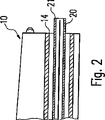
図2に示されるように、手術器具20の先端21が手術ダクト12の基端15から現れるまで、手術ダクト12の先端14内に手術器具20が挿入されてもよい。この位置で、手術器具20の先端21は、内視鏡10のレンズ系11の視野内に配置される。
As shown in FIG. 2, the
本明細書に示される手術器具20は、例えば独国特許発明第41 39 029号明細書又は米国特許第5,207,675号明細書から良く知られるようなAPCプローブである。そのようなプローブはルーメン23を有しており、このルーメン23を経由してガス源28からの不活性ガスが供給されてもよい。ルーメン23の内側には電極24が配置されており、この電極24の基端部はHF外科用器械に対して接続されている。使用時、この手術器具20は、ユーザが手術器具20の先端21を凝固される組織に近づけることができるように、図2に示されるような位置になければならない。したがって、この手術に備えるためには、手術ダクト12内での手術器具20の位置を決定するとともに、手術器具20及びその先端21が手術位置に位置して内視鏡10のレンズ系11により観察できるように手術器具20の位置を調整する必要がある。
The
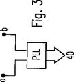
図1に示される本発明の実施形態の場合、手術器具20と手術ダクト12を有する内視鏡10とを備えるシステムの電気的特性は、必要とされる測定値を生成するために使用される。ここで、一方側の手術器具20の電極24及び他方側の手術ダクトの(導電)壁13は測定ブリッジ31に含められており、測定ブリッジ31は、一方側でコンデンサC及び2つのレジスタRを経由した電圧降下を検出して評価装置40に供給され、また、ジェネレータ30からの所定の(低い)電圧を有する高周波信号(300kHz)が他方側を経由してシステムへ供給される。この場合、コンデンサCは、手術器具20が手術ダクト12内に十分に挿入される際にブリッジ31が釣り合わされるように選択されることが好ましい。無論、そのようなブリッジ回路の代わりに、オシレータ回路を使用することができ、その場合、図1からの測定点a,bが周波数決定(容量性)部材の接続点を表わし、それらの共振周波数が測定される。PLL素子を有する同様の回路が図3に示されており、PLL素子の出力信号(同調周波数に対応する)は評価回路40へ供給される。
In the embodiment of the invention shown in FIG. 1, the electrical properties of the system comprising the
評価回路40は、手術器具20が手術ダクト12内にわたって挿入される距離に対応する測定信号を生成する。表示装置41及び必要に応じてラウドスピーカ42がディスプレイとしての機能を果たし、その場合、そのピッチが手術ダクト12内への手術器具20の挿入深さに対応する音響可聴信号が生成されるようになっていてもよい。このとき、(図2に示されるように)手術器具20の先端21が手術ダクト12の先端14から突出し始めると、電極24と内視鏡10及び手術ダクト12の壁13との間のキャパシタンスが変化しなくなり、それにより、術者は手術ダクト12からの先端21の出現を容易に観察することができる。
The
ここで、強調すべきことは、本目的を達成するために多数の電気的測定が可能であるということである。例えば、システムは、それ自体周知の方法で市販の測定器具によりその長さを測定できる損失の多い伝送ラインとして理解される内視鏡10及び手術器具20を備えることができる。
It should be emphasized here that a number of electrical measurements are possible to achieve this objective. For example, the system may comprise an
図4に示される本発明の実施形態の場合には、音響測定システムが設けられている。このシステムは、手術ダクト12の基端15に接続され且つジェネレータ30から可聴信号が供給される電子音響変換器又はラウドスピーカ33を含んでいる。可聴信号は、適当な電気機械変換器、例えばマイクロホン32によって検出され、マイクロホン(プローブマイクロホンについて言えば)には、手術器具20のルーメン23が直列接続されている。変換器32の出力信号は、適切な信号調整後、先と同様に評価回路40に対して供給される。音声レベルにより、先端21が手術ダクト12内に位置している場所、及び、特に先端が手術ダクト12の先端14から突出しているかどうかが確かめられてもよい。これは、この範囲で、検出できる音圧が急に減少するからである。無論、ここでは、2つの音響変換器32,33を交換することができ、それにより、音響信号を手術器具20のルーメン23内に供給することができ、また、手術ダクト12の先端15で音圧を測定することができる。
In the case of the embodiment of the invention shown in FIG. 4, an acoustic measurement system is provided. The system includes an electroacoustic transducer or loudspeaker 33 connected to the proximal end 15 of the
本明細書では図示しない本発明の更なる代替の実施形態の場合、手術器具20が挿入された状態の手術ダクト12の音響特性が決定される。これは、例えば、音響インピーダンスを決定することにより行なわれてもよく、音響インピーダンスは、変換器33における図4に係る構成の場合に得られ且つ手術ダクト12内の手術器具20の侵入深さに依存する。また、同様に、手術ダクト12の内側の音響共振周波数を決定することもでき、この音響共振周波数も手術器具20の侵入深さに依存している。つまり、音響測定は前述した電気的測定と同様に行なわれ、一方で、手術器具20及び手術ダクト12を備えるシステム内の相互作用が決定される。
In a further alternative embodiment of the invention not shown here, the acoustic characteristics of the
図5に示される本発明の代替の実施形態の場合には、「静的」圧力が決定され、この静的圧力は、圧力源34によって生成され、手術ダクト12の基端15内に供給されるとともに、手術器具20のルーメン23を経由して手術器具20の基端22の圧力センサ43へ伝えられて測定される。その後、測定信号は、先と同様に評価装置40に対して供給される。圧力センサ43で現われる圧力は、手術器具20の先端21のガス圧に対応しており、一方、手術器具のルーメン23は、このルーメン23をアルゴンガス源28に対して接続するバルブ29(図1参照)によって閉じられる。あるいは、圧力源34を手術ダクト12に対して接続する代わりに、別個のダクトを経由して、内視鏡10が挿入される体腔へガスを供給(例えば吸入)することもできる。手術器具20は、その後、先端21が手術ダクト12の先端14から現われるときに、基端で開口する手術ダクト12を用いて最大圧を測定する。これは、圧力降下(手術ダクト内の流通に起因する)がもはや起こらないからである。
In the alternative embodiment of the present invention shown in FIG. 5, a “static” pressure is determined, which is generated by a pressure source 34 and supplied into the proximal end 15 of the
本明細書に示される構成又は本明細書に示されるプロセスの適用は、手術器具20の周辺機器の自動制御(例えば、APCプローブとして構成される手術器具20のルーメン23へ不活性ガスを供給するバルブ29を制御する)において特に有利である。この場合、手術器具20の先端21が手術ダクト12から十分大きな量だけ現われると、バルブ29が別個の信号によって解放されて開く(図2及び関連説明を参照)。
Application of the configuration shown herein or the process shown herein provides automatic control of peripheral devices of the surgical instrument 20 (eg, supplying an inert gas to the
本発明の基本的な原理は、内視鏡10の手術ダクト12及び挿入される手術器具20がトータルシステムとして見なされるという旨の前述した説明から生じ、それにより、測定信号を生成する際に2つの部品間の相互作用を利用できる。
The basic principle of the present invention arises from the above explanation that the
10…内視鏡、11…レンズ系、12…手術ダクト、13…手術ダクト壁、14…先端、15…基端、20…手術器具、21…先端、22…基端、23…ルーメン、24…電極、27…HF機器、28…ガス源、29…バルブ、30…ジェネレータ、31…測定ブリッジ、32…マイクロホン、33…ラウドスピーカ、34…圧力源、40…評価装置、41…ディスプレイ(又は表示)装置、42…ラウドスピーカ、43…圧力センサ。
DESCRIPTION OF
Claims (3)
測定信号を生成するためのジェネレータ(30,27)と、
前記測定信号を前記手術ダクト(12)及び前記器具(20)に対して接続するための手段(24,33)と、
前記手術ダクト(12)内での前記位置にしたがって前記器具(20)が前記測定信号に及ぼす位置の影響を測定するとともに、当該影響に応じた表示信号を生成するための測定器(31,32;40)と、
を備え、
前記ジェネレータ(30)が、AC信号又はパルス形状DC信号を前記測定信号として生成し、
前記測定器(31,40)が、前記器具(20)と前記手術ダクト(12)の少なくとも壁(13)の領域との間の複素インピーダンスを位置の影響として測定して前記手術ダクト(12)に対する前記外科用器具(20)の前記位置を決定するように構成されている、装置。An apparatus for measuring the position of a surgical instrument (20) relative to a surgical duct (12) of an endoscope (10) into which the surgical instrument (20) is inserted,
Generators (30, 27) for generating measurement signals;
Means for connecting said measurement signal surgical duct (12) and against the instrument (20) and (24, 33),
Measuring devices (31, 32) for measuring the influence of the position of the instrument (20) on the measurement signal according to the position in the surgical duct (12) and generating a display signal corresponding to the influence. 40) and
With
The generator (30) generates an AC signal or a pulse-shaped DC signal as the measurement signal;
Said measuring device (31, 40) is, the instrument (20) and measured by the surgical duct complex impedance as the influence of the position between at least regions of the wall (13) of the pre-Symbol surgery duct (12) (12 The device is configured to determine the position of the surgical instrument (20) relative to).
ことを特徴とする、請求項1に記載の装置。The said measuring device (31) contains an oscillator circuit or PLL circuit, The said complex impedance is set so that it may become a variable element for determining the resonant frequency of the said oscillator circuit, The said 1st aspect is characterized by the above-mentioned. The device described in 1.
Applications Claiming Priority (3)
| Application Number | Priority Date | Filing Date | Title |
|---|---|---|---|
| DE102004039202.1 | 2004-08-12 | ||
| DE102004039202A DE102004039202B3 (en) | 2004-08-12 | 2004-08-12 | Device for measuring a relative position of a surgical instrument and use thereof |
| PCT/EP2005/008531 WO2006018163A2 (en) | 2004-08-12 | 2005-08-05 | Device for measuring a position of a surgical instrument |
Publications (3)
| Publication Number | Publication Date |
|---|---|
| JP2008508969A JP2008508969A (en) | 2008-03-27 |
| JP2008508969A5 JP2008508969A5 (en) | 2011-07-28 |
| JP4897682B2 true JP4897682B2 (en) | 2012-03-14 |
Family
ID=35355343
Family Applications (1)
| Application Number | Title | Priority Date | Filing Date |
|---|---|---|---|
| JP2007525232A Expired - Fee Related JP4897682B2 (en) | 2004-08-12 | 2005-08-05 | Device for measuring the position of a surgical instrument |
Country Status (6)
| Country | Link |
|---|---|
| US (1) | US20090209809A1 (en) |
| EP (1) | EP1781159A2 (en) |
| JP (1) | JP4897682B2 (en) |
| CN (1) | CN101001564B (en) |
| DE (1) | DE102004039202B3 (en) |
| WO (1) | WO2006018163A2 (en) |
Families Citing this family (10)
| Publication number | Priority date | Publication date | Assignee | Title |
|---|---|---|---|---|
| CN101595350B (en) | 2006-12-11 | 2013-05-29 | Toip控股有限公司 | Heating and cooling system |
| JP4912993B2 (en) * | 2007-09-12 | 2012-04-11 | オリンパスメディカルシステムズ株式会社 | Medical equipment system |
| US10758212B2 (en) | 2011-12-03 | 2020-09-01 | Koninklijke Philips N.V. | Automatic depth scrolling and orientation adjustment for semi-automated path planning |
| US9526856B2 (en) | 2011-12-15 | 2016-12-27 | The Board Of Trustees Of The Leland Stanford Junior University | Devices and methods for preventing tracheal aspiration |
| ES2914993T3 (en) | 2012-05-31 | 2022-06-20 | Baylis Medical Co Inc | Radio Frequency Drilling Apparatus |
| WO2015069804A1 (en) | 2013-11-05 | 2015-05-14 | Ciel Medical, Inc. | Devices and methods for airway measurement |
| JP5855806B1 (en) * | 2014-06-10 | 2016-02-09 | オリンパス株式会社 | Endoscope system, endoscope apparatus and processor |
| EP3189768B1 (en) * | 2014-09-05 | 2019-04-17 | Olympus Corporation | Endoscope system |
| EP3861920A1 (en) | 2020-02-05 | 2021-08-11 | Erbe Elektromedizin GmbH | Surgical instrument with a position detection device |
| KR102284135B1 (en) * | 2021-06-01 | 2021-08-02 | 주식회사 메디인테크 | Endoscope Endoscope with Durability Check Function |
Citations (7)
| Publication number | Priority date | Publication date | Assignee | Title |
|---|---|---|---|---|
| JPS642632A (en) * | 1987-03-26 | 1989-01-06 | Washington Res Found | Ultrasonic imaging system which can be inserted through endocsope |
| JPH0795969A (en) * | 1993-09-29 | 1995-04-11 | Morita Mfg Co Ltd | Device for measuring depth of recessed part of living body and depth measuring probe and calibrating adaptor therefor |
| JPH11313894A (en) * | 1998-02-25 | 1999-11-16 | Biosense Inc | Stent guide arrangement |
| JP2001500749A (en) * | 1996-02-15 | 2001-01-23 | バイオセンス・インコーポレイテッド | Medical method and apparatus using in-vivo probe |
| JP2001524844A (en) * | 1996-12-02 | 2001-12-04 | アンジオトラックス,インコーポレイテッド | Apparatus and method for intraoperative surgery |
| US20030040737A1 (en) * | 2000-03-16 | 2003-02-27 | Merril Gregory L. | Method and apparatus for controlling force for manipulation of medical instruments |
| US6705319B1 (en) * | 2000-05-26 | 2004-03-16 | Purdue Research Foundation | Miniature acoustical guidance and monitoring system for tube or catheter placement |
Family Cites Families (20)
| Publication number | Priority date | Publication date | Assignee | Title |
|---|---|---|---|---|
| DE3536271A1 (en) * | 1985-10-11 | 1987-04-16 | Dornier Medizintechnik | POSITIONING DEVICE FOR AN ELECTRODE |
| DE3712054A1 (en) * | 1987-04-09 | 1988-10-27 | Dieter Dr Fuierer | MEASURING PROCESS FOR DETECTING THE POCKET DEPTH OF DENTAL APPARATUS (PERIODONTICS) |
| US5207675A (en) * | 1991-07-15 | 1993-05-04 | Jerome Canady | Surgical coagulation device |
| US5437290A (en) * | 1991-09-06 | 1995-08-01 | Board Of Trustees Of The Leland Stanford Jr. University | System and method for monitoring intraluminal device position |
| DE4139029C2 (en) * | 1991-11-27 | 1996-05-23 | Erbe Elektromedizin | Device for the coagulation of biological tissues |
| US5331967A (en) * | 1993-02-05 | 1994-07-26 | Playa De Los Vivos S.A. | Tracheal intubation monitoring apparatus and method |
| US5571147A (en) * | 1993-11-02 | 1996-11-05 | Sluijter; Menno E. | Thermal denervation of an intervertebral disc for relief of back pain |
| WO1997029710A1 (en) * | 1996-02-15 | 1997-08-21 | Biosense, Inc. | Medical probes with field transducers |
| EP0812568B1 (en) * | 1996-06-11 | 2003-10-22 | Roke Manor Research Limited | Catheter tracking system |
| CA2216455C (en) * | 1996-10-04 | 2006-12-12 | Jeffrey J. Blewett | Apparatus for thermal treatment of tissue |
| US6102926A (en) * | 1996-12-02 | 2000-08-15 | Angiotrax, Inc. | Apparatus for percutaneously performing myocardial revascularization having means for sensing tissue parameters and methods of use |
| DE19858375B4 (en) * | 1997-07-24 | 2008-07-03 | Erbe Elektromedizin Gmbh | Device for RF coagulation of biological tissues by means of flexible endoscopy |
| US6061588A (en) * | 1998-09-29 | 2000-05-09 | Advanced Cardiovascular Systems, Inc. | Catheter apparatus for positioning a wire |
| DE19955346A1 (en) * | 1999-11-17 | 2001-09-20 | Hans Rudolf Schwind | Endoscope imaging method and endoscope system |
| JP2003522566A (en) * | 1999-12-21 | 2003-07-29 | シャーウッド サーヴィシス アクチェンゲゼルシャフト | Device for thermal treatment of intervertebral disc |
| US6623423B2 (en) * | 2000-02-29 | 2003-09-23 | Olympus Optical Co., Ltd. | Surgical operation system |
| DE10058370A1 (en) * | 2000-11-24 | 2002-06-06 | Hannes Strasser | Ultrasonic probe has a head that is placed in an aspiration guide used for removal of biopsy tissue etc. with the probe head having a positioning device so that it can be precisely positioned to yield positioning images |
| DE10134911A1 (en) * | 2001-07-18 | 2003-02-06 | Hannes Strasser | Ultrasonic probe has a head that is placed in an aspiration guide used for removal of biopsy tissue etc. with the probe head having a positioning device so that it can be precisely positioned to yield positioning images |
| DE10109310A1 (en) * | 2001-02-27 | 2002-09-05 | Detlef Richter | Three-dimensional tracking of probe needles, biopsy needles or surgical instruments using a CT or MRT system with improved tracking provided by undertaking a calibration step using an infrared light source calibration frame |
| CN1374137A (en) * | 2001-03-08 | 2002-10-16 | 潘卫江 | Tracheal catheter position detecting method |
-
2004
- 2004-08-12 DE DE102004039202A patent/DE102004039202B3/en not_active Expired - Fee Related
-
2005
- 2005-08-05 WO PCT/EP2005/008531 patent/WO2006018163A2/en active Application Filing
- 2005-08-05 CN CN2005800268550A patent/CN101001564B/en not_active Expired - Fee Related
- 2005-08-05 JP JP2007525232A patent/JP4897682B2/en not_active Expired - Fee Related
- 2005-08-05 US US11/573,493 patent/US20090209809A1/en not_active Abandoned
- 2005-08-05 EP EP05788656A patent/EP1781159A2/en not_active Withdrawn
Patent Citations (7)
| Publication number | Priority date | Publication date | Assignee | Title |
|---|---|---|---|---|
| JPS642632A (en) * | 1987-03-26 | 1989-01-06 | Washington Res Found | Ultrasonic imaging system which can be inserted through endocsope |
| JPH0795969A (en) * | 1993-09-29 | 1995-04-11 | Morita Mfg Co Ltd | Device for measuring depth of recessed part of living body and depth measuring probe and calibrating adaptor therefor |
| JP2001500749A (en) * | 1996-02-15 | 2001-01-23 | バイオセンス・インコーポレイテッド | Medical method and apparatus using in-vivo probe |
| JP2001524844A (en) * | 1996-12-02 | 2001-12-04 | アンジオトラックス,インコーポレイテッド | Apparatus and method for intraoperative surgery |
| JPH11313894A (en) * | 1998-02-25 | 1999-11-16 | Biosense Inc | Stent guide arrangement |
| US20030040737A1 (en) * | 2000-03-16 | 2003-02-27 | Merril Gregory L. | Method and apparatus for controlling force for manipulation of medical instruments |
| US6705319B1 (en) * | 2000-05-26 | 2004-03-16 | Purdue Research Foundation | Miniature acoustical guidance and monitoring system for tube or catheter placement |
Also Published As
| Publication number | Publication date |
|---|---|
| WO2006018163A8 (en) | 2006-07-27 |
| WO2006018163A3 (en) | 2006-05-11 |
| JP2008508969A (en) | 2008-03-27 |
| WO2006018163A2 (en) | 2006-02-23 |
| US20090209809A1 (en) | 2009-08-20 |
| CN101001564B (en) | 2010-09-15 |
| CN101001564A (en) | 2007-07-18 |
| DE102004039202B3 (en) | 2006-01-19 |
| EP1781159A2 (en) | 2007-05-09 |
Similar Documents
| Publication | Publication Date | Title |
|---|---|---|
| JP4897682B2 (en) | Device for measuring the position of a surgical instrument | |
| JP3151153B2 (en) | Frequency deviation detection circuit and measuring instrument using the same | |
| Stenfelt et al. | Factors contributing to bone conduction: The outer ear | |
| Siegel | Ear‐canal standing waves and high‐frequency sound calibration using otoacoustic emission probes | |
| US5733281A (en) | Ultrasound and impedance feedback system for use with electrosurgical instruments | |
| JP6514188B2 (en) | Electric surgery system | |
| US6837857B2 (en) | Method for the recording of acoustic parameters for the customization of hearing aids | |
| JPH0316860B2 (en) | ||
| JP2001517105A (en) | Inner ear diagnostic device and method | |
| WO2013014662A4 (en) | An integrative system for dental procedures | |
| JP3848364B2 (en) | Apparatus and method for generating an acoustic reflection curve of an ear and measuring its shape | |
| JP2008508969A5 (en) | ||
| JP2000060878A (en) | Root apex position detector | |
| JP2023116459A (en) | Control console supplying driving signal to surgical system | |
| JP2002528158A (en) | Sensing of ear temperature, acoustic reflection and chemical components in the ear | |
| Rabinowitz | Acoustic-reflex effects on the input admittance and transfer characteristics of the human middle-ear. | |
| CN111513725B (en) | Method and system for analyzing middle ear acoustic immittance by using input electrical impedance parameters | |
| JP3490551B2 (en) | Body palpation device | |
| JPH10216124A (en) | Touch sensor probe | |
| JP3691627B2 (en) | Hardness measuring device | |
| JP2749719B2 (en) | Apparatus for measuring patient response to vibration perception | |
| JPH10104146A (en) | Hardness measuring apparatus | |
| RU2735373C1 (en) | Telemetric ultrasound device for diagnosing sensorineural hearing loss | |
| JP2873722B2 (en) | Apical position detection device | |
| US20090130623A1 (en) | Method and apparatus for effecting dental measurements using a body-contacting electrode |
Legal Events
| Date | Code | Title | Description |
|---|---|---|---|
| A621 | Written request for application examination |
Free format text: JAPANESE INTERMEDIATE CODE: A621 Effective date: 20080610 |
|
| A977 | Report on retrieval |
Free format text: JAPANESE INTERMEDIATE CODE: A971007 Effective date: 20110225 |
|
| A131 | Notification of reasons for refusal |
Free format text: JAPANESE INTERMEDIATE CODE: A131 Effective date: 20110308 |
|
| A524 | Written submission of copy of amendment under article 19 pct |
Free format text: JAPANESE INTERMEDIATE CODE: A524 Effective date: 20110608 |
|
| A131 | Notification of reasons for refusal |
Free format text: JAPANESE INTERMEDIATE CODE: A131 Effective date: 20110809 |
|
| A521 | Request for written amendment filed |
Free format text: JAPANESE INTERMEDIATE CODE: A523 Effective date: 20111013 |
|
| TRDD | Decision of grant or rejection written | ||
| A01 | Written decision to grant a patent or to grant a registration (utility model) |
Free format text: JAPANESE INTERMEDIATE CODE: A01 Effective date: 20111213 |
|
| A01 | Written decision to grant a patent or to grant a registration (utility model) |
Free format text: JAPANESE INTERMEDIATE CODE: A01 |
|
| A61 | First payment of annual fees (during grant procedure) |
Free format text: JAPANESE INTERMEDIATE CODE: A61 Effective date: 20111222 |
|
| R150 | Certificate of patent or registration of utility model |
Free format text: JAPANESE INTERMEDIATE CODE: R150 |
|
| FPAY | Renewal fee payment (event date is renewal date of database) |
Free format text: PAYMENT UNTIL: 20150106 Year of fee payment: 3 |
|
| R250 | Receipt of annual fees |
Free format text: JAPANESE INTERMEDIATE CODE: R250 |
|
| R250 | Receipt of annual fees |
Free format text: JAPANESE INTERMEDIATE CODE: R250 |
|
| LAPS | Cancellation because of no payment of annual fees |