RU2672386C1 - Device and method for conversion of first and second input channels at least in one output channel - Google Patents
Device and method for conversion of first and second input channels at least in one output channel Download PDFInfo
- Publication number
- RU2672386C1 RU2672386C1 RU2017143522A RU2017143522A RU2672386C1 RU 2672386 C1 RU2672386 C1 RU 2672386C1 RU 2017143522 A RU2017143522 A RU 2017143522A RU 2017143522 A RU2017143522 A RU 2017143522A RU 2672386 C1 RU2672386 C1 RU 2672386C1
- Authority
- RU
- Russia
- Prior art keywords
- channel
- speaker
- input
- channels
- output
- Prior art date
Links
- 238000006243 chemical reaction Methods 0.000 title claims abstract description 28
- 238000000034 method Methods 0.000 title claims description 44
- 238000012937 correction Methods 0.000 claims description 39
- 238000004091 panning Methods 0.000 claims description 33
- 238000004590 computer program Methods 0.000 claims description 11
- 230000008569 process Effects 0.000 claims description 8
- 238000012545 processing Methods 0.000 abstract description 14
- 230000005236 sound signal Effects 0.000 abstract description 14
- 230000000694 effects Effects 0.000 abstract description 3
- 239000000126 substance Substances 0.000 abstract 1
- 238000009877 rendering Methods 0.000 description 45
- 238000013459 approach Methods 0.000 description 15
- 239000000203 mixture Substances 0.000 description 10
- 239000011159 matrix material Substances 0.000 description 8
- 230000001419 dependent effect Effects 0.000 description 7
- 230000003321 amplification Effects 0.000 description 6
- 210000005069 ears Anatomy 0.000 description 6
- 238000003199 nucleic acid amplification method Methods 0.000 description 6
- 238000012986 modification Methods 0.000 description 5
- 230000004048 modification Effects 0.000 description 5
- 230000003595 spectral effect Effects 0.000 description 5
- 230000005540 biological transmission Effects 0.000 description 3
- 238000001914 filtration Methods 0.000 description 3
- 239000012634 fragment Substances 0.000 description 3
- 230000003993 interaction Effects 0.000 description 3
- 230000008447 perception Effects 0.000 description 3
- 238000012546 transfer Methods 0.000 description 3
- 230000001934 delay Effects 0.000 description 2
- 238000010586 diagram Methods 0.000 description 2
- 238000011156 evaluation Methods 0.000 description 2
- 238000005070 sampling Methods 0.000 description 2
- 230000009466 transformation Effects 0.000 description 2
- 108010076504 Protein Sorting Signals Proteins 0.000 description 1
- 230000002159 abnormal effect Effects 0.000 description 1
- 238000003491 array Methods 0.000 description 1
- 230000008901 benefit Effects 0.000 description 1
- 230000001427 coherent effect Effects 0.000 description 1
- 238000013144 data compression Methods 0.000 description 1
- 230000007423 decrease Effects 0.000 description 1
- 230000006870 function Effects 0.000 description 1
- 230000006872 improvement Effects 0.000 description 1
- 239000000463 material Substances 0.000 description 1
- 238000005259 measurement Methods 0.000 description 1
- 230000000704 physical effect Effects 0.000 description 1
- 238000004321 preservation Methods 0.000 description 1
- 230000004044 response Effects 0.000 description 1
- 230000001629 suppression Effects 0.000 description 1
- 238000000844 transformation Methods 0.000 description 1
- 238000013519 translation Methods 0.000 description 1
Images
Classifications
-
- H—ELECTRICITY
- H04—ELECTRIC COMMUNICATION TECHNIQUE
- H04S—STEREOPHONIC SYSTEMS
- H04S7/00—Indicating arrangements; Control arrangements, e.g. balance control
-
- H—ELECTRICITY
- H04—ELECTRIC COMMUNICATION TECHNIQUE
- H04S—STEREOPHONIC SYSTEMS
- H04S7/00—Indicating arrangements; Control arrangements, e.g. balance control
- H04S7/30—Control circuits for electronic adaptation of the sound field
- H04S7/302—Electronic adaptation of stereophonic sound system to listener position or orientation
- H04S7/303—Tracking of listener position or orientation
-
- G—PHYSICS
- G10—MUSICAL INSTRUMENTS; ACOUSTICS
- G10L—SPEECH ANALYSIS TECHNIQUES OR SPEECH SYNTHESIS; SPEECH RECOGNITION; SPEECH OR VOICE PROCESSING TECHNIQUES; SPEECH OR AUDIO CODING OR DECODING
- G10L19/00—Speech or audio signals analysis-synthesis techniques for redundancy reduction, e.g. in vocoders; Coding or decoding of speech or audio signals, using source filter models or psychoacoustic analysis
-
- H—ELECTRICITY
- H04—ELECTRIC COMMUNICATION TECHNIQUE
- H04R—LOUDSPEAKERS, MICROPHONES, GRAMOPHONE PICK-UPS OR LIKE ACOUSTIC ELECTROMECHANICAL TRANSDUCERS; DEAF-AID SETS; PUBLIC ADDRESS SYSTEMS
- H04R5/00—Stereophonic arrangements
- H04R5/02—Spatial or constructional arrangements of loudspeakers
-
- H—ELECTRICITY
- H04—ELECTRIC COMMUNICATION TECHNIQUE
- H04S—STEREOPHONIC SYSTEMS
- H04S3/00—Systems employing more than two channels, e.g. quadraphonic
- H04S3/002—Non-adaptive circuits, e.g. manually adjustable or static, for enhancing the sound image or the spatial distribution
-
- H—ELECTRICITY
- H04—ELECTRIC COMMUNICATION TECHNIQUE
- H04S—STEREOPHONIC SYSTEMS
- H04S3/00—Systems employing more than two channels, e.g. quadraphonic
- H04S3/008—Systems employing more than two channels, e.g. quadraphonic in which the audio signals are in digital form, i.e. employing more than two discrete digital channels
-
- H—ELECTRICITY
- H04—ELECTRIC COMMUNICATION TECHNIQUE
- H04S—STEREOPHONIC SYSTEMS
- H04S3/00—Systems employing more than two channels, e.g. quadraphonic
- H04S3/02—Systems employing more than two channels, e.g. quadraphonic of the matrix type, i.e. in which input signals are combined algebraically, e.g. after having been phase shifted with respect to each other
-
- H—ELECTRICITY
- H04—ELECTRIC COMMUNICATION TECHNIQUE
- H04S—STEREOPHONIC SYSTEMS
- H04S7/00—Indicating arrangements; Control arrangements, e.g. balance control
- H04S7/30—Control circuits for electronic adaptation of the sound field
-
- H—ELECTRICITY
- H04—ELECTRIC COMMUNICATION TECHNIQUE
- H04S—STEREOPHONIC SYSTEMS
- H04S7/00—Indicating arrangements; Control arrangements, e.g. balance control
- H04S7/30—Control circuits for electronic adaptation of the sound field
- H04S7/302—Electronic adaptation of stereophonic sound system to listener position or orientation
-
- H—ELECTRICITY
- H04—ELECTRIC COMMUNICATION TECHNIQUE
- H04S—STEREOPHONIC SYSTEMS
- H04S7/00—Indicating arrangements; Control arrangements, e.g. balance control
- H04S7/30—Control circuits for electronic adaptation of the sound field
- H04S7/308—Electronic adaptation dependent on speaker or headphone connection
-
- G—PHYSICS
- G10—MUSICAL INSTRUMENTS; ACOUSTICS
- G10L—SPEECH ANALYSIS TECHNIQUES OR SPEECH SYNTHESIS; SPEECH RECOGNITION; SPEECH OR VOICE PROCESSING TECHNIQUES; SPEECH OR AUDIO CODING OR DECODING
- G10L19/00—Speech or audio signals analysis-synthesis techniques for redundancy reduction, e.g. in vocoders; Coding or decoding of speech or audio signals, using source filter models or psychoacoustic analysis
- G10L19/008—Multichannel audio signal coding or decoding using interchannel correlation to reduce redundancy, e.g. joint-stereo, intensity-coding or matrixing
-
- H—ELECTRICITY
- H04—ELECTRIC COMMUNICATION TECHNIQUE
- H04S—STEREOPHONIC SYSTEMS
- H04S2400/00—Details of stereophonic systems covered by H04S but not provided for in its groups
- H04S2400/01—Multi-channel, i.e. more than two input channels, sound reproduction with two speakers wherein the multi-channel information is substantially preserved
-
- H—ELECTRICITY
- H04—ELECTRIC COMMUNICATION TECHNIQUE
- H04S—STEREOPHONIC SYSTEMS
- H04S2400/00—Details of stereophonic systems covered by H04S but not provided for in its groups
- H04S2400/03—Aspects of down-mixing multi-channel audio to configurations with lower numbers of playback channels, e.g. 7.1 -> 5.1
-
- H—ELECTRICITY
- H04—ELECTRIC COMMUNICATION TECHNIQUE
- H04S—STEREOPHONIC SYSTEMS
- H04S2420/00—Techniques used stereophonic systems covered by H04S but not provided for in its groups
- H04S2420/03—Application of parametric coding in stereophonic audio systems
-
- H—ELECTRICITY
- H04—ELECTRIC COMMUNICATION TECHNIQUE
- H04S—STEREOPHONIC SYSTEMS
- H04S7/00—Indicating arrangements; Control arrangements, e.g. balance control
- H04S7/30—Control circuits for electronic adaptation of the sound field
- H04S7/305—Electronic adaptation of stereophonic audio signals to reverberation of the listening space
Landscapes
- Engineering & Computer Science (AREA)
- Physics & Mathematics (AREA)
- Acoustics & Sound (AREA)
- Signal Processing (AREA)
- Multimedia (AREA)
- Mathematical Physics (AREA)
- Computational Linguistics (AREA)
- Health & Medical Sciences (AREA)
- Audiology, Speech & Language Pathology (AREA)
- Human Computer Interaction (AREA)
- Mathematical Optimization (AREA)
- Mathematical Analysis (AREA)
- Pure & Applied Mathematics (AREA)
- Theoretical Computer Science (AREA)
- General Physics & Mathematics (AREA)
- Algebra (AREA)
- Stereophonic System (AREA)
- Time-Division Multiplex Systems (AREA)
Abstract
Description
Настоящая заявка относится к устройству и способу для преобразования первого и второго входных каналов, по меньшей мере, в один выходной канал, и, в частности, к устройству и способу, подходящим для использования при преобразовании формата между различными конфигурациями каналов громкоговорителей.The present application relates to a device and method for converting the first and second input channels to at least one output channel, and, in particular, to a device and method suitable for use in format conversion between different speaker channel configurations.
Инструментальные средства пространственного кодирования аудио известны в данной области техники и стандартизированы, например, в стандарте объемного звучания MPEG. Пространственное кодирование аудио начинается с множества исходных входных, например, пяти или семи входных каналов, которые идентифицируются посредством их размещения в компоновке для воспроизведения, например, в качестве левого канала, центрального канала, правого канала, левого канала объемного звучания, правого канала объемного звучания и канала улучшения низких частот (LFE). Пространственный аудиокодер может извлекать один или более каналов понижающего микширования из исходных каналов и, дополнительно, может извлекать параметрические данные, связанные с пространственными сигнальными метками, такие как межканальные разности уровней в значениях канальной когерентности, межканальные разности фаз, межканальные разности времен и т.д. Один или более каналов понижающего микширования передаются вместе с параметрической вспомогательной информацией, указывающей пространственные сигнальные метки, в пространственный аудиодекодер для декодирования каналов понижающего микширования и ассоциированных параметрических данных, чтобы в итоге получать выходные каналы, которые являются аппроксимированной версией исходных входных каналов. Размещение каналов в выходной компоновке может быть фиксированным, например, как 5.1-формат, 7.1-формат и т.д.Audio spatial encoding tools are known in the art and standardized, for example, in the MPEG surround standard. The spatial encoding of audio begins with a plurality of source inputs, for example, five or seven input channels, which are identified by placing them in a reproduction layout, for example, as a left channel, a center channel, a right channel, a left surround channel, a right surround channel, and Low Frequency Improvement Channel (LFE). The spatial audio encoder can extract one or more downmix channels from the original channels and, optionally, can extract parametric data associated with the spatial signal labels, such as inter-channel level differences in channel coherence values, inter-channel phase differences, inter-channel time differences, etc. One or more downmix channels are transmitted, along with parametric auxiliary information indicating spatial signal labels, to a spatial audio decoder for decoding the downmix channels and associated parametric data to ultimately receive output channels, which are an approximated version of the original input channels. The placement of channels in the output layout can be fixed, for example, as a 5.1 format, 7.1 format, etc.
Кроме того, инструментальные средства пространственного кодирования аудиообъектов известны в данной области техники и стандартизированы, например, в MPEG SAOC-стандарте (SAOC – пространственное кодирование аудиообъектов). В отличие от пространственного кодирования аудио, начинающегося с исходных каналов, пространственное кодирование аудиообъектов начинается с аудиообъектов, которые автоматически не выделяются для определенной компоновки для воспроизведения при рендеринге. Наоборот, размещение аудиообъектов в сцене для воспроизведения является гибким и может задаваться пользователем, например, посредством ввода определенной информации рендеринга в декодер по стандарту пространственного кодирования аудиообъектов. Альтернативно или дополнительно, информация рендеринга может передаваться в качестве дополнительной вспомогательной информации или метаданных; информация рендеринга может включать в себя информацию того, в какой позиции в компоновке для воспроизведения определенный должен быть размещен аудиообъект (например, во времени). Чтобы получать определенное сжатие данных, определенное число аудиообъектов кодируется с использованием SAOC-кодера, который вычисляет, из входных объектов, один или более транспортных каналов посредством понижающего микширования объектов в соответствии с определенной информацией понижающего микширования. Кроме того, SAOC-кодер вычисляет параметрическую вспомогательную информацию, представляющую межобъектные сигнальные метки, такую как разности уровней объектов (OLD), значения когерентности объектов и т.д. Аналогично SAC (SAC – пространственное кодирование аудио), межобъектные параметрические данные вычисляются для отдельных частотно-временных мозаичных фрагментов. Для определенного кадра (например, 1024 или 2048 выборок) аудиосигнала, рассматриваются множество полос частот (например, 24, 32 или 64 полосы частот), так что параметрические данные предоставляются для каждого кадра и каждой полосы частот. Например, когда аудио фрагмент имеет 20 кадров, и когда каждый кадр подразделяется на 32 полосы частот, число частотно-временных мозаичных фрагментов равно 640.In addition, tools for spatial encoding of audio objects are known in the art and are standardized, for example, in the MPEG SAOC standard (SAOC - spatial encoding of audio objects). Unlike spatial encoding of audio starting from the original channels, spatial encoding of audio objects begins with audio objects that are not automatically allocated for a specific layout for playback during rendering. On the contrary, the placement of audio objects in the scene for playback is flexible and can be set by the user, for example, by entering certain rendering information into a decoder according to the standard for spatial encoding of audio objects. Alternatively or additionally, rendering information may be conveyed as additional supporting information or metadata; rendering information may include information about at what position in the layout for playing a particular audio object should be placed (for example, in time). In order to obtain a specific data compression, a certain number of audio objects are encoded using a SAOC encoder that calculates, from the input objects, one or more transport channels by downmixing the objects in accordance with the specific downmix information. In addition, the SAOC encoder calculates parametric auxiliary information representing inter-object signal labels, such as object level differences (OLD), object coherence values, etc. Similar to SAC (SAC - spatial audio coding), interobject parametric data are calculated for individual time-frequency mosaic fragments. For a particular frame (e.g., 1024 or 2048 samples) of an audio signal, multiple frequency bands (e.g., 24, 32, or 64 frequency bands) are considered, so that parametric data is provided for each frame and each frequency band. For example, when an audio fragment has 20 frames, and when each frame is divided into 32 frequency bands, the number of time-frequency mosaic fragments is 640.
Требуемый формат воспроизведения, т.е. конфигурация выходных каналов (конфигурация выходных громкоговорителей) может отличаться от конфигурации входных каналов, при этом число выходных каналов, в общем, отличается от числа входных каналов. Таким образом, преобразование формата может требоваться для того, чтобы преобразовывать входные каналы из конфигурации входных каналов в выходные каналы из конфигурации выходных каналов.Required playback format, i.e. the configuration of the output channels (the configuration of the output speakers) may differ from the configuration of the input channels, while the number of output channels, in general, differs from the number of input channels. Thus, format conversion may be required in order to convert the input channels from the input channel configuration to the output channels from the output channel configuration.
Задача, лежащая в основе изобретения, заключается в том, чтобы предоставлять устройство и способ, которые разрешают улучшенное воспроизведение звука, в частности, в случае преобразования формата между различными конфигурациями каналов громкоговорителей.The task underlying the invention is to provide a device and method that enable improved sound reproduction, in particular in the case of format conversion between different speaker channel configurations.
Эта задача решается посредством устройства по п. 1 и способа по п. 12.This problem is solved by the device according to p. 1 and the method according to p. 12.
Варианты осуществления изобретения предоставляют устройство для преобразования первого входного канала и второго входного канала из конфигурации входных каналов, по меньшей мере, в один выходной канал из конфигурации выходных каналов, при этом каждый входной канал и каждый выходной канал имеет направление, в котором расположен ассоциированный громкоговоритель относительно центральной позиции слушателя, при этом устройство выполнено с возможностью:Embodiments of the invention provide an apparatus for converting a first input channel and a second input channel from an input channel configuration to at least one output channel from an output channel configuration, wherein each input channel and each output channel has a direction in which an associated speaker is located relative to the central position of the listener, while the device is configured to:
- преобразовывать первый входной канал в первый выходной канал из конфигурации выходных каналов; и, по меньшей мере, одно из следующего:- convert the first input channel to the first output channel from the configuration of the output channels; and at least one of the following:
a) преобразовывать второй входной канал в первый выходной канал, что содержит обработку второго входного канала посредством применения, по меньшей мере, одного из частотного корректирующего фильтра и декорреляционного фильтра ко второму входному каналу; иa) converting the second input channel into a first output channel, which comprises processing the second input channel by applying at least one of a frequency correction filter and a decorrelation filter to the second input channel; and
b) несмотря на тот факт, что отклонение углов между направлением второго входного канала и направлением первого выходного канала меньше отклонения углов между направлением второго входного канала и второго выходного канала и/или меньше отклонения углов между направлением второго входного канала и направлением третьего выходного канала, преобразовывать второй входной канал во второй и третий выходные каналы посредством панорамирования между вторым и третьим выходными каналами.b) despite the fact that the deviation of the angles between the direction of the second input channel and the direction of the first output channel is less than the deviation of the angles between the direction of the second input channel and the second output channel and / or less than the deviation of the angles between the direction of the second input channel and the direction of the third output channel, convert the second input channel to the second and third output channels by panning between the second and third output channels.
Варианты осуществления изобретения предоставляют способ для преобразования первого входного канала и второго входного канала из конфигурации входных каналов, по меньшей мере, в один выходной канал из конфигурации выходных каналов, при этом каждый входной канал и каждый выходной канал имеет направление, в котором расположен ассоциированный громкоговоритель относительно центральной позиции слушателя, содержащий:Embodiments of the invention provide a method for converting a first input channel and a second input channel from an input channel configuration to at least one output channel from an output channel configuration, wherein each input channel and each output channel has a direction in which an associated speaker is located relative to a listener's central position, comprising:
- преобразование первого входного канала в первый выходной канал из конфигурации выходных каналов; и, по меньшей мере, одно из следующего:- converting the first input channel to the first output channel from the configuration of the output channels; and at least one of the following:
a) преобразование второго входного канала в первый выходной канал, содержащее обработку второго входного канала посредством применения, по меньшей мере, одного из частотного корректирующего фильтра и декорреляционного фильтра ко второму входному каналу; иa) converting the second input channel into a first output channel, comprising processing the second input channel by applying at least one of a frequency correction filter and a decorrelation filter to the second input channel; and
b) несмотря на тот факт, что отклонение углов между направлением второго входного канала и направлением первого выходного канала меньше отклонения углов между направлением второго входного канала и второго выходного канала и/или меньше отклонения углов между направлением второго входного канала и направлением третьего выходного канала, преобразование второго входного канала во второй и третий выходные каналы посредством панорамирования между вторым и третьим выходными каналами.b) despite the fact that the deviation of the angles between the direction of the second input channel and the direction of the first output channel is less than the deviation of the angles between the direction of the second input channel and the second output channel and / or less than the deviation of the angles between the direction of the second input channel and the direction of the third output channel, the conversion the second input channel to the second and third output channels by panning between the second and third output channels.
Варианты осуществления изобретения основаны на таких выявленных сведениях, что улучшенное воспроизведение аудио может достигаться даже в случае процесса понижающего микширования из определенного числа входных каналов в меньшее число выходных каналов, если используется подход, который спроектирован с возможностью пытаться сохранять пространственное разнесение, по меньшей мере, двух входных каналов, которые преобразуются, по меньшей мере, в один выходной канал. Согласно вариантам осуществления изобретения, это достигается посредством обработки одного из входных каналов, преобразованных в идентичный выходной канал, посредством применения, по меньшей мере, одного из частотного корректирующего фильтра и декорреляционного фильтра. В вариантах осуществления изобретения, это достигается посредством формирования фантомного источника для одного из входных каналов с использованием двух выходных каналов, по меньшей мере, один из которых имеет отклонение углов из входного канала, который превышает отклонение углов из входного канала в другой выходной канал.Embodiments of the invention are based on such identified evidence that improved audio reproduction can be achieved even in the case of a downmix process from a certain number of input channels to a smaller number of output channels, if an approach that is designed to attempt to maintain spatial diversity of at least two input channels that are converted to at least one output channel. According to embodiments of the invention, this is achieved by processing one of the input channels converted to an identical output channel, by applying at least one of a frequency correction filter and a decorrelation filter. In embodiments of the invention, this is achieved by forming a phantom source for one of the input channels using two output channels, at least one of which has a deviation of angles from the input channel that is greater than the deviation of the angles from the input channel to the other output channel.
В вариантах осуществления изобретения, частотный корректирующий фильтр применяется ко второму входному каналу и выполнен с возможностью повышать спектральную часть второго входного канала, который, как известно, создает у слушателя впечатление, что звук исходит из позиции, соответствующей позиции второго входного канала. В вариантах осуществления изобретения, угол подъема второго входного канала может превышать угол подъема одного или более выходных каналов, в которые преобразуется входной канал. Например, громкоговоритель, ассоциированный со вторым входным каналом, может находиться в позиции выше горизонтальной плоскости слушателя, в то время как громкоговорители, ассоциированные с одним или более выходных каналов, могут находиться в позиции в горизонтальной плоскости слушателя. Частотный корректирующий фильтр может быть выполнен с возможностью повышать спектральную часть второго канала в частотном диапазоне между 7 кГц и 10 кГц. Посредством обработки второго входного сигнала таким способом, у слушателя может создаваться впечатление, что звук исходит из приподнятой позиции, даже если он фактически не исходит из приподнятой позиции.In embodiments of the invention, a frequency correction filter is applied to the second input channel and is configured to increase the spectral part of the second input channel, which, as you know, gives the listener the impression that the sound comes from a position corresponding to the position of the second input channel. In embodiments of the invention, the elevation angle of the second input channel may exceed the elevation angle of one or more output channels into which the input channel is converted. For example, the speaker associated with the second input channel may be in a position above the horizontal plane of the listener, while the speakers associated with one or more output channels may be in the position in the horizontal plane of the listener. The frequency correction filter may be configured to increase the spectral part of the second channel in the frequency range between 7 kHz and 10 kHz. By processing the second input signal in this way, the listener may get the impression that the sound comes from a raised position, even if it does not actually come from a raised position.
В вариантах осуществления изобретения, второй входной канал обрабатывается посредством применения частотного корректирующего фильтра, выполненного с возможностью обрабатывать второй входной канал, чтобы компенсировать разности тембра, вызываемые посредством различных позиций второго входного канала и, по меньшей мере, одного выходного канала, в который преобразуется второй входной канал. Таким образом, тембр второго входного канала, который воспроизводится посредством громкоговорителя в неправильной позиции, может манипулироваться таким образом, что у пользователя может складываться впечатление, что звук возникает из другой позиции, ближе к исходной позиции, т.е. из позиции второго входного канала.In embodiments of the invention, the second input channel is processed by applying a frequency correction filter configured to process the second input channel to compensate for tonal differences caused by different positions of the second input channel and at least one output channel into which the second input channel is converted channel. Thus, the timbre of the second input channel, which is reproduced by the speaker in the wrong position, can be manipulated in such a way that the user may have the impression that the sound comes from a different position, closer to the original position, i.e. from the position of the second input channel.
В вариантах осуществления изобретения, декорреляционный фильтр применяется ко второму входному каналу. Применение декорреляционного фильтра ко второму входному каналу также может создавать у слушателя впечатление, что звуковые сигналы, воспроизведенные посредством первого выходного канала, возникают из различных входных каналов, расположенных в различных позициях в конфигурации входных каналов. Например, декорреляционный фильтр может быть выполнен с возможностью вводить частотно-зависимые задержки и/или рандомизированные фазы во второй входной канал. В вариантах осуществления изобретения, декорреляционный фильтр может представлять собой реверберационный фильтр, выполненный с возможностью вводить части сигнала реверберации во второй входной канал, так что у слушателя может складываться впечатление, что звуковые сигналы, воспроизведенные через первый выходной канал, возникают из различных позиций. В вариантах осуществления изобретения, декорреляционный фильтр может быть выполнен с возможностью свертывать второй входной канал с экспоненциально затухающей шумовой последовательностью, чтобы моделировать рассеянные отражения во втором входном сигнале.In embodiments of the invention, a decorrelation filter is applied to the second input channel. Applying a decorrelation filter to the second input channel can also give the listener the impression that the audio signals reproduced by the first output channel arise from various input channels located at different positions in the input channel configuration. For example, a decorrelation filter may be configured to introduce frequency dependent delays and / or randomized phases into a second input channel. In embodiments of the invention, the decorrelation filter may be a reverberation filter configured to input portions of the reverb signal to the second input channel, so that the listener may have the impression that the audio signals reproduced through the first output channel arise from different positions. In embodiments of the invention, the decorrelation filter may be configured to collapse the second input channel with an exponentially decaying noise sequence to simulate diffuse reflections in the second input signal.
В вариантах осуществления изобретения, коэффициенты частотного корректирующего фильтра и/или декорреляционного фильтра задаются на основе измеренной бинауральной импульсной характеристики в помещении (BRIR) для конкретного помещения для прослушивания или задаются на основе эмпирических знаний относительно акустики помещений (которые также могут учитывать конкретное помещение для прослушивания). Таким образом, соответствующая обработка, чтобы учитывать пространственное разнесение входных каналов, может быть адаптирована через конкретную обстановку, к примеру, конкретное помещение для прослушивания, в котором сигнал должен воспроизводиться посредством конфигурации выходных каналов.In embodiments of the invention, the coefficients of the frequency correction filter and / or decorrelation filter are set based on the measured binaural impulse response in the room (BRIR) for a particular listening room or are set based on empirical knowledge regarding room acoustics (which may also take into account a specific listening room) . Thus, appropriate processing to take into account the spatial diversity of the input channels can be adapted through a specific environment, for example, a specific listening room in which the signal must be reproduced by the configuration of the output channels.
Ниже поясняются варианты осуществления изобретения со ссылкой на прилагаемые чертежи, на которых:Embodiments of the invention are explained below with reference to the accompanying drawings, in which:
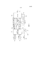
Фиг. 1 показывает общее представление трехмерного аудиокодера трехмерной аудиосистемы;FIG. 1 shows an overview of a three-dimensional audio encoder of a three-dimensional audio system;
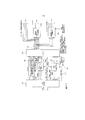
Фиг. 2 показывает общее представление трехмерного аудиодекодера трехмерной аудиосистемы;FIG. 2 shows an overview of a three-dimensional audio decoder of a three-dimensional audio system;
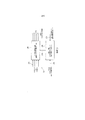
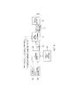
Фиг. 3 показывает пример для реализации преобразователя форматов, который может реализовываться в трехмерном аудиодекодере по фиг. 2;FIG. 3 shows an example for implementing a format converter, which may be implemented in the three-dimensional audio decoder of FIG. 2;
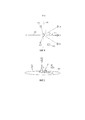
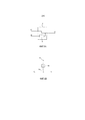
Фиг. 4 показывает схематичный вид сверху конфигурации громкоговорителей;FIG. 4 shows a schematic top view of a speaker configuration;
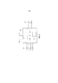
Фиг. 5 показывает схематичный вид сзади другой конфигурации громкоговорителей;FIG. 5 shows a schematic rear view of another speaker configuration;
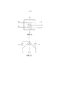
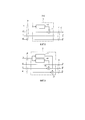
Фиг. 6a и 6b показывают схематичные виды устройства для преобразования первого и второго входных каналов в выходной канал;FIG. 6a and 6b show schematic views of a device for converting the first and second input channels to an output channel;
Фиг. 7a и 7b показывают схематичные виды устройства для преобразования первого и второго входных каналов в несколько выходных каналов;FIG. 7a and 7b show schematic views of a device for converting the first and second input channels to multiple output channels;
Фиг. 8 показывает схематичный вид устройства для преобразования первого и второго канала в один выходной канал;FIG. 8 shows a schematic view of a device for converting a first and second channel into a single output channel;
Фиг. 9 показывает схематичный вид устройства для преобразования первого и второго входных каналов в различные выходные каналы;FIG. 9 shows a schematic view of a device for converting the first and second input channels to various output channels;
Фиг. 10 показывает блок-схему процессора сигналов для преобразования входных каналов из конфигурации входных каналов в выходные каналы из конфигурации выходных каналов;FIG. 10 shows a block diagram of a signal processor for converting input channels from an input channel configuration to output channels from an output channel configuration;
Фиг. 11 показывает процессор сигналов; иFIG. 11 shows a signal processor; and
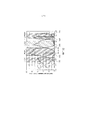
Фиг. 12 является схемой, показывающей так называемые полосы частот Блоерта.FIG. 12 is a diagram showing so-called Bloert frequency bands.
Перед подробным описанием вариантов осуществления изобретательского подхода, приводится краткое представление системы трехмерных аудиокодеков, в которой может реализовываться изобретательский подход.Before a detailed description of embodiments of the inventive approach, a brief presentation of a three-dimensional audio codec system is provided in which an inventive approach can be implemented.
Фиг. 1 и 2 показывают алгоритмические блоки трехмерной аудиосистемы в соответствии с вариантами осуществления. Более конкретно, фиг. 1 показывает общее представление трехмерного аудиокодера 100. Аудиокодер 100 принимает в схеме 102 модуля предварительного рендеринга/микшера, которая необязательно может быть предоставлена, входные сигналы, более конкретно множество входных каналов, предоставляющих в аудиокодер 100 множество сигналов 104 каналов, множество сигналов 106 объектов и соответствующих метаданных 108 объектов. Сигналы 106 объектов, обработанные посредством модуля предварительного рендеринга/микшера 102 (см. сигналы 110), может предоставляться в SAOC-кодер 112 (SAOC–пространственное кодирование аудиообъектов). SAOC-кодер 112 формирует транспортные SAOC-каналы 114, предоставленные для входов USAC-кодера 116 (USAC– стандартизированное кодирование речи и аудио). Помимо этого, SAOC-SI 118 сигналов (SAOC-SI – вспомогательная информация SAOC) также предоставляется во входы USAC-кодера 116. USAC-кодер 116 дополнительно принимает сигналы 120 объектов непосредственно из модуля предварительного рендеринга/микшера, а также сигналы каналов и предварительно подготовленные посредством рендеринга сигналы 122 объектов. Информация 108 метаданных объектов применяется к OAM-кодеру 124 (OAM–метаданные объектов), предоставляющему сжатую информацию 126 метаданных объектов в USAC-кодер. USAC-кодер 116, на основе вышеуказанных входных сигналов, формирует сжатый выходной сигнал MP4, как показано на 128.FIG. 1 and 2 show the algorithmic blocks of a three-dimensional audio system in accordance with embodiments. More specifically, FIG. 1 shows an overview of a three-
Фиг. 2 показывает общее представление трехмерного аудиодекодера 200 трехмерной аудиосистемы. Кодированный сигнал 128 (MP4), сформированный посредством аудиокодера 100 по фиг. 1, принимается в аудиодекодере 200, более конкретно в USAC-декодере 202. USAC-декодер 202 декодирует принимаемый сигнал 128 в сигналы 204 каналов, предварительно подготовленные посредством рендеринга сигналы 206 объектов, сигналы 208 объектов и сигналы 210 транспортных SAOC-каналов. Дополнительно, сжатая информация 212 метаданных объектов и SAOC-SI 214 сигналов выводится посредством USAC-декодера. Сигналы 208 объектов предоставляются в модуль 216 рендеринга объектов, выводящий подготовленные посредством рендеринга сигналы 218 объектов. Сигналы 210 транспортных SAOC-каналов предоставляются в SAOC-декодер 220, выводящий подготовленные посредством рендеринга сигналы 222 объектов. Сжатая метаинформация 212 объектов предоставляется в OAM-декодер 224, выводящий соответствующие управляющие сигналы в модуль 216 рендеринга объектов и SAOC-декодер 220 для формирования подготовленных посредством рендеринга сигналов 218 объектов и подготовленных посредством рендеринга сигналов 222 объектов. Декодер дополнительно содержит микшер 226, принимающий, как показано на фиг. 2, входные сигналы 204, 206, 218 и 222 для вывода сигналов 228 каналов. Сигналы каналов могут непосредственно выводиться в громкоговоритель, например, 32-канальный громкоговоритель, как указано на 230. Альтернативно, сигналы 228 могут предоставляться в схему 232 преобразования форматов, принимающую в качестве управляющего ввода сигнал схемы размещения для воспроизведения, указывающий способ, которым должны преобразовываться сигналы 228 каналов. В варианте осуществления, проиллюстрированном на фиг. 2, предполагается, что преобразование должно выполняться таким образом, что сигналы могут предоставляться в акустическую 5.1-систему, как указано на 234. Кроме того, сигналы 228 каналов предоставляются в модуль 236 бинаурального рендеринга, формирующий два выходных сигнала, например, для наушника, как указано на 238.FIG. 2 shows an overview of a three-
Система кодирования/декодирования, проиллюстрированная на фиг. 1 и 2, может быть основана на MPEG-D USAC-кодеке для кодирования сигналов каналов и объектов (см. сигналы 104 и 106). Чтобы повышать эффективность для кодирования большого количества объектов, может использоваться MPEG SAOC-технология. Три типа модулей рендеринга могут выполнять задачи рендеринга объектов в каналы, рендеринга каналов в наушники или рендеринга каналов в другую компоновку громкоговорителей (см. фиг. 2, ссылки с номерами 230, 234 и 238). Когда сигналы объектов явно передаются или параметрически кодируются с использованием SAOC, соответствующая информация 108 метаданных объектов сжимается (см. сигнал 126) и мультиплексируется в трехмерный поток 128 аудиобитов.The encoding / decoding system illustrated in FIG. 1 and 2 can be based on the MPEG-D USAC codec for encoding channel and object signals (see
Фиг. 1 и 2 показывают алгоритмические блоки для полной трехмерной аудиосистемы, которая подробнее описывается ниже.FIG. 1 and 2 show the algorithmic blocks for a full three-dimensional audio system, which is described in more detail below.
Модуль 102 предварительного рендеринга/микшер необязательно может быть предоставлен для того, чтобы преобразовывать сцену ввода каналов плюс объектов в сцену каналов перед кодированием. Функционально, он является идентичным модулю рендеринга объектов/микшеру, который подробно описывается ниже. Предварительный рендеринг объектов может требоваться для того, чтобы обеспечивать детерминированную энтропию сигналов на входе кодера, которая по существу является независимой от числа одновременно активных сигналов объектов. При предварительном рендеринге объектов, не требуется передача метаданных объектов. Сигналы дискретных объектов подготовлены посредством рендеринга в схему размещения каналов, которую кодер выполнен с возможностью использовать. Весовые коэффициенты объектов для каждого канала получаются из ассоциированных метаданных объектов (OAM).A pre-rendering /
USAC-кодер 116 представляет собой базовый кодек для сигналов каналов громкоговорителя, сигналов дискретных объектов, сигналов понижающего микширования объектов и предварительно подготовленных посредством рендеринга сигналов. Он основан на MPEG-D USAC-технологии. Он обрабатывает кодирование вышеуказанных сигналов посредством создания информации преобразования каналов и объектов на основе геометрической и семантической информации назначения входных каналов и объектов. Эта информация преобразования описывает то, как входные каналы и объекты преобразуются в USAC-канальные элементы, такие как элементы канальных пар (CPE), одноканальные элементы (SCE), низкочастотные эффекты (LFE) и элементы канальных четверок (QCE), и CPE, SCE и LFE и соответствующая информация передается в декодер. Все дополнительные SAOC-данные 114, 118 в форме рабочих данных или метаданные 126 объектов рассматриваются при управлении скоростью кодеров. Кодирование объектов является возможным различными способами, в зависимости от требований по искажению в зависимости от скорости передачи и требований по интерактивности для модуля рендеринга. В соответствии с вариантами осуществления, возможны следующие варианты кодирования объектов:
Предварительно подготовленные посредством рендеринга объекты: Сигналы объектов подготавливаются посредством рендеринга и сводятся в 22.2-канальные сигналы перед кодированием. Последующая цепочка кодирования видит 22.2-канальные сигналы.Pre-prepared by rendering objects: Signals of objects are prepared by rendering and are reduced to 22.2-channel signals before encoding. The subsequent coding chain sees 22.2-channel signals.
Формы сигналов дискретных объектов: Объекты предоставляются в качестве монофонических форм сигнала в кодер. Кодер использует одноканальные элементы (SCE), чтобы передавать объекты в дополнение к сигналам каналов. Декодированные объекты подготавливаются посредством рендеринга и сводятся на стороне приемного устройства. Сжатая информация метаданных объектов передается в приемное устройство/модуль рендеринга.Signal waveforms of discrete objects: Objects are provided as monophonic waveforms to an encoder. The encoder uses single channel elements (SCEs) to transmit objects in addition to channel signals. Decoded objects are prepared by rendering and reduced on the side of the receiving device. Compressed object metadata information is transmitted to the receiver / rendering module.
Формы сигналов параметрических объектов: Свойства объектов и их взаимосвязь между собой описываются посредством SAOC-параметров. Понижающее микширование сигналов объектов кодируется с помощью USAC. Параметрическая информация передается совместно. Число каналов понижающего микширования выбирается в зависимости от числа объектов и полной скорости передачи данных. Сжатая информация метаданных объектов передается в модуль SAOC-рендеринга.Waveforms of parametric objects: The properties of objects and their relationship to each other are described by means of SAOC parameters. The downmix of object signals is encoded using USAC. Parametric information is transmitted together. The number of down-mix channels is selected depending on the number of objects and the total data rate. Compressed object metadata information is passed to the SAOC rendering module.
SAOC-кодер 112 и SAOC-декодер 220 для сигналов объектов могут быть основаны на MPEG SAOC-технологии. Система допускает повторное создание, модификацию и рендеринг определенного числа аудиообъектов на основе меньшего числа передаваемых каналов и дополнительных параметрических данных, таких как OLD, IOC (межобъектная когерентность), DMG (усиления при понижающем микшировании). Дополнительные параметрические данные демонстрируют значительно более низкую скорость передачи данных, чем требуется для передачи всех объектов по отдельности, что делает кодирование очень эффективным. SAOC-кодер 112 принимает в качестве ввода сигналы объектов/каналов в качестве монофонических форм сигнала и выводит параметрическую информацию (которая пакетирована в трехмерный поток 128 аудиобитов) и транспортные SAOC-каналы (которые кодируются с использованием одноканальных элементов и передаются). SAOC-декодер 220 восстанавливает сигналы объектов/каналов из декодированных транспортных SAOC-каналов 210 и параметрической информации 214 и формирует выходную аудиосцену на основе схемы размещения для воспроизведения, распакованной информации метаданных объектов и необязательно на основе информации пользовательского взаимодействия.The
Кодек метаданных объектов (см. OAM-кодер 124 и OAM-декодер 224) предоставляется таким образом, что для каждого объекта, ассоциированные метаданные, которые указывают геометрическую позицию и объем объектов в трехмерном пространстве, эффективно кодируются посредством квантования свойств объектов во времени и пространстве. Сжатые метаданные 126 объектов (cOAM) передаются в приемное устройство 200 в качестве вспомогательной информации.An object metadata codec (see
Модуль 216 рендеринга объектов использует сжатые метаданные объектов для того, чтобы формировать формы сигналов объектов согласно данному формату воспроизведения. Каждый объект подготавливается посредством рендеринга в определенный выходной канал 218 согласно своим метаданным. Вывод этого блока получается в результате суммы частичных результатов. Если декодируются как канальный контент, так и дискретные/параметрические объекты, канальные формы сигналов и подготовленные посредством рендеринга формы сигналов объектов сводятся посредством микшера 226 перед выводом результирующих форм 228 сигналов или перед их подачей в модуль постпроцессора, такой как модуль 236 бинаурального рендеринга или модуль 232 рендеринга громкоговорителей.
Модуль 236 бинаурального рендеринга формирует бинауральное понижающее микширование многоканального аудиоматериала таким образом, что каждый входной канал представлен посредством виртуального источника звука. Обработка осуществляется покадрово в области QMF (гребенки квадратурных зеркальных фильтров), и бинаурализация основана на измеренных бинауральных импульсных характеристиках в помещении.The
Модуль 232 рендеринга громкоговорителей преобразует между конфигурацией 228 передаваемых каналов и требуемым форматом воспроизведения. Он также может называться "преобразователем форматов". Преобразователь форматов выполняет преобразования в меньшие числа выходных каналов, т.е. он создает понижающего микширования.A
Возможная реализация преобразователя 232 форматов показана на фиг. 3. В вариантах осуществления изобретения, процессор сигналов представляет собой такой преобразователь форматов. Преобразователь 232 форматов, также называемый "модулем рендеринга громкоговорителей", преобразует между конфигурацией каналов передающего устройства и требуемым форматом воспроизведения посредством преобразования (входных) каналов передающего устройства из конфигурации (входных) каналов передающего устройства в (выходные) каналы требуемого формата воспроизведения (конфигурации выходных каналов). Преобразователь 232 форматов, в общем, выполняет преобразования в меньшее число выходных каналов, т.е. он выполняет процесс 240 понижающего микширования (DMX). Понижающий микшер 240, который предпочтительно работает в QMF-области, принимает выходные сигналы 228 микшера и выводит сигналы 234 громкоговорителей. Может предоставляться конфигуратор 242, также называемый "контроллером", который принимает, в качестве управляющего ввода, сигнал 246, указывающий схему размещения выходов микшера (конфигурацию входных каналов), т.е. схему размещения, для которой определяются данные, представленные посредством выходного сигнала 228 микшера, и сигнал 248, указывающий требуемую схему размещения для воспроизведения (конфигурацию выходных каналов). На основе этой информации, контроллер 242, предпочтительно автоматически, формирует матрицы понижающего микширования для данной комбинации форматов ввода и вывода и применяет эти матрицы к понижающему микшеру 240. Преобразователь 232 форматов обеспечивает возможность стандартных конфигураций громкоговорителей, а также случайных конфигураций с нестандартными позициями громкоговорителей.A possible implementation of the
Варианты осуществления настоящего изобретения относятся к реализации модуля 232 рендеринга громкоговорителей, т.е. к устройствам и способам для реализации части функциональности модуля 232 рендеринга громкоговорителей.Embodiments of the present invention relate to the implementation of a
Теперь следует обратиться к фиг. 4 и 5. Фиг. 4 показывает конфигурацию громкоговорителей, представляющую 5.1-формат, содержащий шесть громкоговорителей, представляющих левый канал LC, центральный канал CC, правый канал RC, левый канал LSC объемного звучания, правый канал LRC объемного звучания и канал LFC улучшения низких частот. Фиг. 5 показывает другую конфигурацию громкоговорителей, содержащую громкоговорители, представляющие левый канал LC, центральный канал CC, правый канал RC и приподнятый центральный канал ECC.Now refer to FIG. 4 and 5. FIG. 4 shows a speaker configuration representing a 5.1 format comprising six speakers representing a left LC channel, a center CC channel, a right RC channel, a left surround channel LSC, a right surround channel LRC, and a low frequency enhancement channel LFC. FIG. 5 shows another speaker configuration comprising speakers representing the left channel LC, the center channel CC, the right channel RC and the raised center channel ECC.
Далее, канал улучшения низких частот не рассматривается, поскольку точная позиция громкоговорителя (сабвуфера), ассоциированного с каналом улучшения низких частот, не является важной.Further, the bass enhancement channel is not considered, since the exact position of the speaker (subwoofer) associated with the bass enhancement channel is not important.
Каналы размещаются в конкретных направлениях относительно центральной позиции P слушателя. Направление каждого канала задается посредством азимутального угла α и угла β подъема, см. фиг. 5. Азимутальный угол представляет угол канала в горизонтальной плоскости 300 слушателя и может представлять направление соответствующего канала относительно переднего центрального направления 302. Как можно видеть на фиг. 4, переднее центральное направление 302 может задаваться как предполагаемое направление просмотра слушателя, расположенного в центральной позиции P слушателя. Заднее центральное направление 304 содержит азимутальный угол 180° относительно переднего центрального направления 300. Все азимутальные углы слева от переднего центрального направления между передним центральным направлением и задним центральным направлением находятся на левой стороне переднего центрального направления, и все азимутальные углы справа от переднего центрального направления между передним центральным направлением и задним центральным направлением находятся на правой стороне переднего центрального направления. Громкоговорители, расположенные перед виртуальной линией 306, которая является ортогональной к переднему центральному направлению 302 и передает центральную позицию P слушателя, являются передними громкоговорителями, и громкоговорители, расположенные позади виртуальной линии 306, являются задними громкоговорителями. В 5.1-формате азимутальный угол α канала LC составляет 30° влево, α CC составляет 0°, α RC составляет 30° вправо, α LSC составляет 110° влево, и α RSC составляет 110° вправо.Channels are placed in specific directions relative to the center position P of the listener. The direction of each channel is defined by the azimuthal angle α and the angle β of elevation, see FIG. 5. The azimuthal angle represents the angle of the channel in the
Угол β подъема канала задает угол между горизонтальной плоскостью 300 слушателя и направлением виртуальной соединительной линии между центральной позицией слушателя и громкоговорителем, ассоциированным с каналом. В конфигурации, показанной на фиг. 4, все громкоговорители размещаются в горизонтальной плоскости 300 слушателя, и в силу этого все углы подъема являются нулевыми. На фиг. 5, угол β подъема канала ECC может составлять 30°. Громкоговоритель, расположенный строго выше центральной позиции слушателя, должен иметь угол подъема в 90°. Громкоговорители, размещаемые ниже горизонтальной плоскости 300 слушателя, имеют отрицательный угол подъема. На фиг. 5, LC имеет направление x1, CC имеет направление x2, RC имеет направление x3, и ECC имеет направление x4.The elevation angle β of the channel defines the angle between the
Позиция конкретного канала в пространстве, т.е. позиция громкоговорителя, ассоциированная с конкретным каналом, задается посредством азимутального угла, угла подъема и расстояния громкоговорителя от центральной позиции слушателя. Следует отметить, что термин "позиция громкоговорителя" зачастую описывается специалистами в данной области техники посредством ссылки только на азимутальный угол и угол подъема.The position of a particular channel in space, i.e. the speaker position associated with a particular channel is specified by azimuthal angle, elevation angle and distance of the speaker from the center position of the listener. It should be noted that the term “loudspeaker position” is often described by those skilled in the art by reference only to the azimuthal angle and the angle of elevation.
Обычно, преобразование формата между различными конфигурациями каналов громкоговорителей выполняется в качестве процесса понижающего микширования, который преобразует определенное число входных каналов в определенное число выходных каналов, при этом число выходных каналов, в общем, меньше числа входных каналов, при этом позиции выходных каналов могут отличаться от позиций входных каналов. Один или более входных каналов могут сводиться вместе в идентичный выходной канал. Одновременно, один или более входных каналов могут быть подготовлены посредством рендеринга более чем для одного выходного канала. Это преобразование из входных каналов в выходной канал типично определяется посредством набора коэффициентов понижающего микширования или альтернативно формулируется в качестве матрицы понижающего микширования. Выбор коэффициентов понижающего микширования значительно влияет на достижимое качество выводимого звука при понижающем микшировании. Плохие варианты выбора могут приводить к несбалансированному сведению или плохому пространственному воспроизведению входной звуковой сцены.Typically, format conversion between different speaker channel configurations is performed as a downmix process that converts a certain number of input channels to a certain number of output channels, while the number of output channels is generally less than the number of input channels, and the positions of the output channels may differ from input channel positions. One or more input channels may be combined together into an identical output channel. At the same time, one or more input channels can be prepared by rendering for more than one output channel. This conversion from the input channels to the output channel is typically determined by a set of down-mix coefficients or alternatively formulated as a down-mix matrix. The choice of downmix coefficients significantly affects the achievable quality of the output sound during downmix. Bad choices can result in unbalanced mixing or poor spatial reproduction of the input sound stage.
Каждый канал имеет ассоциированный аудиосигнал, который должен воспроизводиться посредством ассоциированного громкоговорителя. Такая идея, что конкретный канал обрабатывается (к примеру, посредством применения коэффициента, посредством применения частотного корректирующего фильтра или посредством применения декорреляционного фильтра), означает то, что обрабатывается соответствующий аудиосигнал, ассоциированный с этим каналом. В контексте данной заявки, термин "частотный корректирующий фильтр" предназначен, чтобы охватывать любое средство для того, чтобы применять частотную коррекцию к сигналу таким образом, что достигается частотно-зависимое взвешивание частей сигнала. Например, частотный корректирующий фильтр может быть выполнен с возможностью применять частотно-зависимые коэффициенты усиления к полосам частот сигнала. В контексте данной заявки, термин "декорреляционный фильтр" предназначен, чтобы охватывать любое средство для того, чтобы применять декорреляцию к сигналу, к примеру, посредством введения частотно-зависимых задержек и/или рандомизированных фаз в сигнал. Например, декорреляционный фильтр может быть выполнен с возможностью применять коэффициенты частотно-зависимой задержки к полосам частот сигнала и/или применять рандомизированные фазовые коэффициенты к сигналу.Each channel has an associated audio signal to be reproduced by an associated speaker. The idea that a particular channel is being processed (for example, by applying a coefficient, by applying a frequency correction filter or by applying a decorrelation filter) means that the corresponding audio signal associated with that channel is being processed. In the context of this application, the term “frequency correction filter” is intended to encompass any means for applying frequency correction to a signal such that a frequency dependent weighting of signal portions is achieved. For example, a frequency correction filter may be configured to apply frequency dependent gain factors to signal frequency bands. In the context of this application, the term “decorrelation filter” is intended to encompass any means for applying decorrelation to a signal, for example, by introducing frequency-dependent delays and / or randomized phases into the signal. For example, a decorrelation filter may be configured to apply frequency dependent delay coefficients to signal frequency bands and / or to apply randomized phase coefficients to a signal.
В вариантах осуществления изобретения, преобразование входного канала в один или более выходных каналов включает в себя применение, по меньшей мере, одного коэффициента, который должен применяться к входному каналу, для каждого выходного канала, в который преобразуется входной канал. По меньшей мере, один коэффициент может включать в себя коэффициент усиления, т.е. значение усиления, которое должно применяться к входному сигналу, ассоциированному с входным каналом, и/или коэффициент задержки, т.е. значение задержки, которое должно применяться к входному сигналу, ассоциированному с входным каналом. В вариантах осуществления изобретения, преобразование может включать в себя применение частотно-избирательных коэффициентов, т.е. различных коэффициентов для различных полос частот входных каналов. В вариантах осуществления изобретения, преобразование входных каналов в выходные каналы включает в себя формирование одной или более матриц коэффициентов из коэффициентов. Каждая матрица задает коэффициент, который должен применяться к каждому входному каналу из конфигурации входных каналов для каждого выходного канала из конфигурации выходных каналов. Для выходных каналов, в которые не преобразуется входной канал, соответствующий коэффициент в матрице коэффициентов является нулевым. В вариантах осуществления изобретения, могут формироваться отдельные матрицы коэффициентов для коэффициентов усиления и коэффициентов задержки. В вариантах осуществления изобретения, матрица коэффициентов для каждой полосы частот может формироваться в случае, если коэффициенты являются частотно-избирательными. В вариантах осуществления изобретения, преобразование дополнительно может включать в себя применение извлеченных коэффициентов ко входным сигналам, ассоциированным с входными каналами.In embodiments of the invention, converting the input channel to one or more output channels includes applying at least one coefficient to be applied to the input channel for each output channel into which the input channel is converted. At least one coefficient may include a gain, i.e. the gain value to be applied to the input signal associated with the input channel and / or the delay coefficient, i.e. the delay value to be applied to the input signal associated with the input channel. In embodiments of the invention, the conversion may include applying frequency selective coefficients, i.e. different coefficients for different frequency bands of the input channels. In embodiments of the invention, converting the input channels to output channels includes generating one or more matrixes of coefficients from the coefficients. Each matrix defines a coefficient to be applied to each input channel from the input channel configuration for each output channel from the output channel configuration. For output channels into which the input channel is not converted, the corresponding coefficient in the coefficient matrix is zero. In embodiments of the invention, separate matrixes of coefficients for the gains and delay coefficients can be formed. In embodiments of the invention, a matrix of coefficients for each frequency band may be formed if the coefficients are frequency selective. In embodiments of the invention, the conversion may further include applying the extracted coefficients to the input signals associated with the input channels.
Чтобы получать хорошие коэффициенты понижающего микширования, эксперт (например, звукооператор) может вручную настраивать коэффициенты, с учетом своих экспертных знаний. Другая возможность состоит в том, чтобы автоматически извлекать коэффициенты понижающего микширования для данной комбинации входных и выходных конфигураций посредством трактовки каждого входного канала как виртуального источника звука, позиция которого в пространстве задается посредством позиции в пространстве, ассоциированной с конкретным каналом, т.е. позиции громкоговорителя, ассоциированной с конкретным входным каналом. Каждый виртуальный источник может воспроизводиться посредством общего алгоритма панорамирования, такого как панорамирование по теореме тангенсов в двумерном случае или векторное амплитудное панорамирование (VBAP) в трехмерном случае, см работу V. Pulkki: "Virtual Sound Source Positioning Using Vector Base Amplitude Panning", Journal of the Audio Engineering Society, издание 45, стр. 456-466, 1997 год. Другой проект для математического, т.е. автоматического извлечения коэффициентов понижающего микширования для данной комбинации входных и выходных конфигураций приведен в работе автора A. Ando: "Conversion of Multichannel Sound Signal Maintaining Physical Properties of Sound in Reproduced Sound Field", IEEE Transactions on Audio, Speech and Language Processing, издание 19, номер. 6, август 2011 года.In order to get good down-mix coefficients, an expert (for example, a sound engineer) can manually adjust the coefficients based on their expert knowledge. Another possibility is to automatically extract the down-mix coefficients for a given combination of input and output configurations by treating each input channel as a virtual sound source, whose position in space is specified by the position in space associated with a particular channel, i.e. loudspeaker position associated with a particular input channel. Each virtual source can be reproduced using a general panning algorithm, such as panning according to the tangent theorem in the two-dimensional case or vector amplitude panning (VBAP) in the three-dimensional case, see V. Pulkki: "Virtual Sound Source Positioning Using Vector Base Amplitude Panning", Journal of the Audio Engineering Society, 45 edition, pp. 456-466, 1997. Another project for math, i.e. Automatically extracting down-mix coefficients for a given combination of input and output configurations is given by A. Ando: "Conversion of Multichannel Sound Signal Maintaining Physical Properties of Sound in Reproduced Sound Field", IEEE Transactions on Audio, Speech and Language Processing, vol. 19, number. August 6, 2011.
Соответственно, существующие подходы на основе понижающего микширования в основном основаны на трех стратегиях извлечения коэффициентов понижающего микширования. Первая стратегия представляет собой прямое преобразование отброшенных входных каналов в выходные каналы в идентичной или сравнимой азимутальной позиции. Смещения подъема отбрасываются. Например, установившейся практикой является то, чтобы подготавливать посредством рендеринга высотные каналы непосредственно с горизонтальными каналами в идентичной или сравнимой азимутальной позиции, если высотный уровень не присутствует в конфигурации выходных каналов. Вторая стратегия представляет собой использование общих алгоритмов панорамирования, которые трактуют входные каналы как виртуальные источники звука и сохраняют информацию азимута посредством введения фантомных источников в позициях отброшенных входных каналов. Смещения подъема отбрасываются. В способах предшествующего уровня техники, панорамирование используется только в том случае, если отсутствует доступный выходной громкоговоритель в требуемой выходной позиции, например, под требуемым азимутальным углом. Третья стратегия представляет собой внедрение экспертных знаний для извлечения оптимальных коэффициентов понижающего микширования в эмпирическом, художественном или психоакустическом смысле. Может использоваться отдельное или комбинированное применение различных стратегий.Accordingly, existing downmix approaches are mainly based on three strategies for extracting downmix coefficients. The first strategy is the direct conversion of discarded input channels to output channels in an identical or comparable azimuthal position. Lift offsets are discarded. For example, it is well established practice to render high-altitude channels directly with horizontal channels in the same or comparable azimuthal position by rendering if the altitude level is not present in the configuration of the output channels. The second strategy is to use common panning algorithms that treat input channels as virtual sound sources and store azimuth information by introducing phantom sources at the positions of the discarded input channels. Lift offsets are discarded. In prior art methods, panning is only used if there is no available output speaker at the desired output position, for example, at the desired azimuth angle. The third strategy is the introduction of expert knowledge to extract the optimal down-mix coefficients in an empirical, artistic or psychoacoustic sense. Separate or combined use of various strategies may be used.
Варианты осуществления изобретения предоставляют техническое решение, позволяющее улучшать или оптимизировать процесс понижающего микширования таким образом, что могут получаться выходные сигналы понижающего микширования более высокого качества, чем без использования этого решения. В вариантах осуществления, решение может повышать качество понижающего микширования в случаях, если пространственное разнесение, внутренне присущее в конфигурации входных каналов, теряется в ходе понижающего микширования без применения предлагаемого решения.Embodiments of the invention provide a technical solution to improve or optimize the downmix process so that higher quality downmix output signals can be obtained than without using this solution. In embodiments, the solution can improve the quality of the downmix in cases where the spatial diversity intrinsic to the configuration of the input channels is lost during the downmix without applying the proposed solution.
С этой целью, варианты осуществления изобретения обеспечивают возможность сохранения пространственного разнесения, которое является внутренне присущим в конфигурации входных каналов, и которое не сохраняется посредством простого подхода на основе понижающего микширования (DMX). В сценариях понижающего микширования, в которых уменьшается число акустических каналов, варианты осуществления изобретения в основном направлены на уменьшение потерь разнесения и огибания, которые неявно возникают при преобразовании из большего в меньшее число каналов.To this end, embodiments of the invention provide the ability to maintain spatial diversity, which is intrinsic to the configuration of the input channels, and which is not saved through a simple approach based on downmix (DMX). In downmix scenarios in which the number of acoustic channels is reduced, embodiments of the invention are mainly aimed at reducing the diversity and envelope losses that implicitly occur when converting from a larger to a smaller number of channels.
Авторы изобретения выяснили, что в зависимости от конкретной конфигурации, внутренне присущее пространственное разнесение и пространственное огибание конфигурации входных каналов зачастую значительно снижается или полностью теряется в конфигурации выходных каналов. Кроме того, если акустические события одновременно воспроизводятся из нескольких динамиков во входной конфигурации, они становятся более когерентными, уплотненными и сфокусированными в выходной конфигурации. Это может приводить к перцепционно более давящему пространственному впечатлению, которое зачастую кажется менее приятным, чем для конфигурации входных каналов. Варианты осуществления изобретения направлены на явное сохранение пространственного разнесения в конфигурации выходных каналов в первый раз. Варианты осуществления изобретения направлены на сохранение воспринимаемого местоположения акустического события максимально близким по сравнению со случаем использования исходной конфигурации громкоговорителей входных каналов.The inventors have found that, depending on the specific configuration, the inherent spatial diversity and spatial envelope of the configuration of the input channels is often significantly reduced or completely lost in the configuration of the output channels. In addition, if acoustic events are simultaneously reproduced from several speakers in the input configuration, they become more coherent, densified, and focused in the output configuration. This can lead to a perceptually more oppressive spatial impression, which often seems less pleasant than for the configuration of the input channels. Embodiments of the invention are aimed at explicitly maintaining spatial diversity in the configuration of the output channels for the first time. Embodiments of the invention are aimed at keeping the perceived location of the acoustic event as close as possible compared with the case of using the initial configuration of the input channel speakers.
Соответственно, варианты осуществления изобретения предоставляют конкретный подход преобразования первого входного канала и второго входного канала, которые ассоциированы с различными позициями громкоговорителей конфигурации входных каналов, и, следовательно, содержат пространственное разнесение, по меньшей мере, в один выходной канал. В вариантах осуществления изобретения, первый и второй входные каналы имеют различные подъемы относительно горизонтальной плоскости слушателя. Таким образом, смещения подъема между первым входным каналом и вторым входным каналом могут учитываться, чтобы улучшать воспроизведение звука с использованием громкоговорителей конфигурации выходных каналов.Accordingly, embodiments of the invention provide a specific conversion approach for the first input channel and the second input channel, which are associated with different positions of the speaker configurations of the input channels, and therefore comprise spatial diversity in at least one output channel. In embodiments of the invention, the first and second input channels have different elevations relative to the horizontal plane of the listener. Thus, the lift offsets between the first input channel and the second input channel can be taken into account in order to improve sound reproduction using the speakers of the output channel configuration.
В контексте данной заявки, разнесение может описываться следующим образом. Различные громкоговорители конфигурации входных каналов приводят к различным акустическим каналам из громкоговорителей в уши, к примеру, в уши слушателя в позиции P. Предусмотрено определенное число прямых акустических трактов и определенное число непрямых акустических трактов, также известных как отражения или реверберация, которые являются следствием различной степени оживленности помещения для прослушивания и которые добавляют дополнительную декорреляцию и изменения тембра в воспринимаемые сигналы из различных позиций громкоговорителей. Акустические каналы могут полностью моделироваться посредством BRIR, которые являются характерными для каждого помещения для прослушивания. Восприятие при прослушивании конфигурации входных каналов строго зависит от характерной комбинации различных входных каналов и разнообразных BRIR, которые соответствуют конкретным позициям громкоговорителей. Таким образом, разнесение и огибание являются результатом различных модификаций сигналов, которые внутренне применяются ко всем сигналам громкоговорителей посредством помещения для прослушивания.In the context of this application, explode may be described as follows. Different loudspeakers of the input channel configuration lead to different acoustic channels from the loudspeakers to the ears, for example, to the listener's ears in position P. There are a certain number of direct acoustic paths and a certain number of indirect acoustic paths, also known as reflections or reverbs, which result from varying degrees liveliness of the listening room and which add additional decorrelation and timbre changes to the perceived signals from various loud positions voriteley. Acoustic channels can be fully modeled by BRIR, which are characteristic of each listening room. The perception of listening to the configuration of the input channels is strictly dependent on the characteristic combination of various input channels and various BRIRs that correspond to specific speaker positions. Thus, diversity and envelope are the result of various signal modifications that are internally applied to all speaker signals through the listening room.
Далее приводится обоснование необходимости подходов на основе понижающего микширования, которые сохраняют пространственное разнесение конфигурации входных каналов. Конфигурация входных каналов может использовать большее число громкоговорителей, чем для конфигурации выходных каналов, либо может использовать, по меньшей мере, один громкоговоритель, не присутствующий в конфигурации выходных громкоговорителей. Просто в качестве иллюстрации, конфигурация входных каналов может использовать громкоговорители LC, CC, RC, ECC, как показано на фиг. 5, в то время как конфигурация выходных каналов может использовать только громкоговорители LC, CC и RC, т.е. не использует громкоговоритель ECC. Таким образом, конфигурация входных каналов может использовать более высокое число уровней воспроизведения, чем конфигурация выходных каналов. Например, конфигурация входных каналов может предоставлять горизонтальные (LC, CC, RC) и высотные (ECC) динамики, тогда как выходная конфигурация может только предоставлять горизонтальные динамики (LC, CC, RC). Таким образом, число акустических каналов из громкоговорителя в уши уменьшается с конфигурацией выходных каналов в ситуациях понижающего микширования. В частности, трехмерные (например, 22.2) в двумерные (например, 5.1) понижающего микширования (DMX) затрагиваются больше всего вследствие отсутствия различных уровней для воспроизведения в конфигурации выходных каналов. Степени свободы, чтобы достигать аналогичного восприятия при прослушивании с конфигурацией выходных каналов относительно разнесения и огибания, уменьшаются, и, следовательно, ограничиваются. Варианты осуществления изобретения предоставляют подходы на основе понижающего микширования, которые улучшают сохранение пространственного разнесения конфигурации входных каналов, при этом описанные устройства и способы не ограничены каким-либо конкретным видом подхода на основе понижающего микширования и могут применяться в различных контекстах и вариантах применения.The following is a rationale for the need for downmix approaches that preserve spatial diversity of the input channel configuration. The configuration of the input channels may use a larger number of speakers than for the configuration of the output channels, or may use at least one speaker not present in the configuration of the output speakers. Just as an illustration, the configuration of the input channels can use the speakers LC, CC, RC, ECC, as shown in FIG. 5, while the configuration of the output channels can only use the speakers LC, CC and RC, i.e. Doesn't use an ECC speaker. Thus, the configuration of the input channels can use a higher number of playback levels than the configuration of the output channels. For example, the configuration of the input channels can provide horizontal (LC, CC, RC) and high-altitude (ECC) speakers, while the output configuration can only provide horizontal speakers (LC, CC, RC). Thus, the number of speaker channels from the speaker to the ears decreases with the configuration of the output channels in down-mix situations. In particular, three-dimensional (e.g., 22.2) to two-dimensional (e.g., 5.1) downmix (DMX) are most affected due to the lack of different levels for playback in the output channel configuration. The degrees of freedom in order to achieve a similar listening experience with the configuration of the output channels with respect to diversity and envelope are reduced, and therefore limited. Embodiments of the invention provide downmix approaches that improve spatial diversity preservation of input channel configurations, and the described devices and methods are not limited to any particular type of downmix approach and can be applied in various contexts and applications.
Далее описываются варианты осуществления изобретения со ссылкой на конкретный сценарий, показанный на фиг. 5. Тем не менее, описанные проблемы и решения могут быть легко адаптированы к другим сценариям с аналогичными условиями. Без потери общности, допускаются следующие конфигурации входных и выходных каналов:Embodiments of the invention will now be described with reference to the specific scenario shown in FIG. 5. However, the described problems and solutions can be easily adapted to other scenarios with similar conditions. Without loss of generality, the following configurations of input and output channels are allowed:
Конфигурация входных каналов: четыре громкоговорителя LC, CC, RC и ECC в позициях x1=(α1, β1), x2=(α2, β1), x3=(α3, β1) и x4=(α4, β2), где α2≈α4 или α2=α4.Input channel configuration: four loudspeakers LC, CC, RC and ECC at positions x 1 = (α 1 , β 1 ), x 2 = (α 2 , β 1 ), x 3 = (α 3 , β 1 ) and x 4 = (α 4 , β 2 ), where α2≈α 4 or α 2 = α 4 .
Конфигурация выходных каналов: три громкоговорителя в позиции x1=(α1, β1), x2=(α2, β1) и x3=(α3, β1), т.е. громкоговоритель в позиции x4 отбрасывается в понижающем микшировании; α представляет азимутальный угол, и β представляет угол подъема.The configuration of the output channels: three speakers at the position x 1 = (α 1 , β 1 ), x 2 = (α 2 , β 1 ) and x 3 = (α 3 , β 1 ), i.e. the speaker at position x 4 is dropped in the downmix; α represents the azimuthal angle, and β represents the elevation angle.
Как пояснено выше, простой DMX-подход должен приоритезировать сохранение направленной информации азимута и просто игнорировать все смещения подъема. Таким образом, сигналы из громкоговорителя ECC в позиции x4 должны просто передаваться в громкоговоритель CC в позиции x2. Тем не менее, при этом теряются характеристики. Во-первых, теряются разности тембра вследствие различных BRIR, которые внутренне применяются в позициях x2 и x4 воспроизведения. Во-вторых, теряется пространственное разнесение входных сигналов, которые воспроизводятся в различных позициях x2 и x4. В-третьих, теряется внутренне присущая декорреляция входных сигналов вследствие различных акустических трактов распространения из позиций x2 и x4 в уши слушателей.As explained above, a simple DMX approach should prioritize the storage of directional azimuth information and simply ignore all lift offsets. Thus, the signals from the ECC speaker at position x 4 should simply be transmitted to the CC speaker at position x 2 . However, performance is lost. First, tonal differences are lost due to the different BRIRs that are internally applied at the x 2 and x 4 positions of the reproduction. Secondly, the spatial diversity of input signals is lost, which are reproduced at different positions x 2 and x 4 . Third, the intrinsic decorrelation of input signals is lost due to various acoustic propagation paths from positions x 2 and x 4 into the ears of the listeners.
Варианты осуществления изобретения направлены на сохранение или имитацию одной или более описанных характеристик посредством применения стратегий, поясненных в данном документе, отдельно или в комбинации для процесса понижающего микширования.Embodiments of the invention seek to preserve or simulate one or more of the described characteristics by applying the strategies described herein, alone or in combination for a downmix process.
Фиг. 6a и 6b показывают схематичные виды для пояснения устройства 10 для реализации стратегии, в которой первый входной канал 12 и второй входной канал 14 преобразуются в идентичный выходной канал 16, при этом обработка второго входного канала выполняется посредством применения, по меньшей мере, одного из частотного корректирующего фильтра и декорреляционного фильтра ко второму входному каналу. Эта обработка указывается на фиг. 6a посредством блока 18.FIG. 6a and 6b show schematic views for explaining a
Специалистам в данной области техники должно быть понятным, что устройства, поясненные и описанные в настоящей заявке, могут реализовываться посредством соответствующих компьютеров или процессоров, сконфигурированных и/или запрограммированных с возможностью получать описанную функциональность. Альтернативно, устройства могут реализовываться как другие программируемые аппаратные структуры, к примеру, как программируемые пользователем вентильные матрицы и т.п.Specialists in the art should understand that the devices explained and described in this application can be implemented using appropriate computers or processors configured and / or programmed to receive the described functionality. Alternatively, the devices may be implemented as other programmable hardware structures, for example, as user-programmable gate arrays and the like.
Первый входной канал 12 на фиг. 6a может быть ассоциирован с центральным громкоговорителем CC в направлении x2, и второй входной канал 14 может быть ассоциирован с приподнятым центральным громкоговорителем ECC в позиции x4 (в конфигурации входных каналов, соответственно). Выходной канал 16 может быть ассоциирован с центральным громкоговорителем ECC в позиции x2 (в конфигурации выходных каналов). Фиг. 6b иллюстрирует то, что канал 14, ассоциированный с громкоговорителем в позиции x4, преобразуется в первый выходной канал 16, ассоциированный с громкоговорителем CC в позиции x2, и то, что это преобразование содержит обработку 18 второго входного канала 14, т.е. обработку аудиосигнала, ассоциированного со вторым входным каналом 14. Обработка второго входного канала содержит применение, по меньшей мере, одного из частотного корректирующего фильтра и декорреляционного фильтра ко второму входному каналу, чтобы сохранять различные характеристики между первым и вторым входными каналами в конфигурации входных каналов. В вариантах осуществления, частотный корректирующий фильтр и/или декорреляционный фильтр могут быть выполнены с возможностью сохранять характеристики относительно разностей тембра вследствие различных BRIR, которые внутренне применяются в различных позициях x2 и x4 громкоговорителей, ассоциированных с первым и вторым входными каналами. В вариантах осуществления изобретения, частотный корректирующий фильтр и/или декорреляционный фильтр выполнены с возможностью сохранять пространственное разнесение входных сигналов, которые воспроизводятся в различных позициях, так что пространственное разнесение первого и второго входного канала остается воспринимаемым несмотря на тот факт, что первый и второй входные каналы преобразуются в идентичный выходной канал.The
В вариантах осуществления изобретения, декорреляционный фильтр выполнен с возможностью сохранять внутренне присущую декорреляцию входных сигналов вследствие различных акустических трактов распространения из различных позиций громкоговорителей, ассоциированных с первым и вторым входными каналами с ушами слушателя.In embodiments of the invention, the decorrelation filter is configured to maintain an intrinsic decorrelation of the input signals due to various acoustic propagation paths from different positions of the speakers associated with the first and second input channels with the listener's ears.
В варианте осуществления изобретения, частотный корректирующий фильтр применяется ко второму входному каналу, т.е. к аудиосигналу, ассоциированному со вторым входным каналом в позиции x4, если он микширован с понижением в громкоговоритель CC в позиции x2. Частотный корректирующий фильтр компенсирует изменения тембра различных акустических каналов и может извлекаться на основе эмпирических экспертных знаний и/или измеренных BRIR-данных и т.п. Например, предполагается, что конфигурация входных каналов предоставляет канал гласа Божьего (VoG) при подъеме в 90°. Если конфигурация выходных каналов предоставляет только громкоговорители на одном уровне, и VoG-канал отбрасывается, как, например, в выходной 5.1-конфигурации, очень простой подход заключается в том, чтобы распределять VoG-канал во все выходные громкоговорители, чтобы сохранять направленную информацию VoG-канала, по меньшей мере, в зоне наилучшего восприятия. Тем не менее, исходный VoG-громкоговоритель воспринимается достаточно по-разному вследствие различной BRIR. Посредством применения выделенного частотного корректирующего фильтра к VoG-каналу перед распределением во все выходные громкоговорители может компенсироваться разность тембра.In an embodiment of the invention, a frequency correction filter is applied to the second input channel, i.e. to the audio signal associated with the second input channel at position x 4 if it is downmixed to the CC speaker at position x 2 . A frequency correction filter compensates for changes in the timbre of various acoustic channels and can be extracted based on empirical expert knowledge and / or measured BRIR data, etc. For example, it is assumed that the configuration of the input channels provides the voice of God (VoG) channel at a 90 ° rise. If the configuration of the output channels provides only the speakers at the same level and the VoG channel is discarded, as, for example, in the output 5.1 configuration, a very simple approach is to distribute the VoG channel to all output speakers in order to store directional VoG information channel, at least in the zone of best perception. However, the original VoG speaker is perceived quite differently due to the different BRIRs. By applying a dedicated frequency correction filter to the VoG channel, the tone difference can be compensated before being distributed to all output speakers.
В вариантах осуществления изобретения, частотный корректирующий фильтр может быть выполнен с возможностью осуществлять частотно-зависимое взвешивание соответствующего входного канала, чтобы учитывать психоакустические выявленные сведения относительно направленного восприятия аудиосигналов. Примером таких выявленных сведений являются так называемые полосы частот Блоерта, представляющие полосы частот определения направления. Фиг. 12 показывает три графика 20, 22 и 24, представляющие вероятность того, что распознается конкретное направление аудиосигналов. Как видно из графика 20, аудиосигналы сверху могут распознаваться с высокой вероятностью в полосе 1200 частот между 7 кГц и 10 кГц или. Как видно из графика 22, аудиосигналы сзади могут распознаваться с высокой вероятностью в полосе 1202 частот приблизительно от 0,7 кГц приблизительно до 2 кГц и в полосе 1204 частот приблизительно от 10 кГц приблизительно до 12,5 кГц. Как видно из графика 24, аудиосигналы спереди могут распознаваться с высокой вероятностью в полосе 1206 частот приблизительно от 0,3 кГц до 0,6 кГц и в полосе 1208 частот приблизительно от 2,5 приблизительно до 5,5 кГц.In embodiments of the invention, the frequency correction filter may be configured to perform frequency-dependent weighting of the corresponding input channel in order to take into account the psychoacoustic detected information regarding the directional perception of audio signals. An example of such identified information is the so-called Bloert frequency bands, representing the direction determining frequency bands. FIG. 12 shows three
В вариантах осуществления изобретения, частотный корректирующий фильтр сконфигурирован с использованием этого распознавания. Другими словами, частотный корректирующий фильтр может быть выполнен с возможностью применять более высокие коэффициенты усиления (повышение) к полосам частот, которые, как известно, создают у пользователя впечатление, что звук исходит из конкретных направлений, по сравнению с другими полосами частот. Более конкретно, в случае если входной канал преобразуется в нижний выходной канал, спектральная часть входного канала в диапазоне полосы 1200 частот между 7 кГц и 10 кГц может быть повышена, по сравнению с другими спектральными частями вторых входных каналов, так что у слушателя может складываться впечатление, что соответствующий сигнал возникает из приподнятой позиции. Аналогично, частотный корректирующий фильтр может быть выполнен с возможностью повышать другие спектральные части второго входного канала, как показано на фиг. 12. Например, в случае если входной канал преобразуется в выходной канал, размещаемый в более выдвинутой вперед позиции, полосы 1206 и 1208 частот могут быть повышены, а в случае, если входной канал преобразуется в выходной канал, размещаемый в находящейся дальше сзади позиции, полосы 1202 и 1204 частот могут быть повышены.In embodiments of the invention, the frequency correction filter is configured using this recognition. In other words, the frequency correction filter can be configured to apply higher gain (increase) to frequency bands, which, as you know, give the user the impression that the sound comes from specific directions, compared with other frequency bands. More specifically, if the input channel is converted to a lower output channel, the spectral part of the input channel in the range of the 1200 frequency band between 7 kHz and 10 kHz can be increased compared to other spectral parts of the second input channels, so that the listener may get the impression that the corresponding signal arises from a raised position. Similarly, the frequency correction filter may be configured to enhance other spectral parts of the second input channel, as shown in FIG. 12. For example, if the input channel is converted to an output channel placed in a more advanced position, the
В вариантах осуществления изобретения, устройство выполнено с возможностью применять декорреляционный фильтр ко второму входному каналу. Например, декорреляционный/реверберационный фильтр может применяться к входному сигналу, ассоциированному со вторым входным каналом (ассоциированному с громкоговорителем в позиции x4), если он микширован с понижением в громкоговоритель в позиции x2. Такой декорреляционный/реверберационный фильтр может извлекаться из BRIR-измерений или эмпирических знаний относительно акустики помещений и т.п. Если входной канал преобразуется в несколько выходных каналов, сигнал фильтра может воспроизводиться по нескольким громкоговорителям, причем для каждого громкоговорителя могут применяться различные фильтры. Фильтр(ы) также может моделировать только ранние отражения.In embodiments of the invention, the device is configured to apply a decorrelation filter to the second input channel. For example, a decorrelation / reverb filter can be applied to an input signal associated with a second input channel (associated with a speaker at position x 4 ) if it is downmixed to a speaker at position x 2 . Such a decorrelation / reverberation filter can be derived from BRIR measurements or empirical knowledge regarding room acoustics, etc. If the input channel is converted to multiple output channels, the filter signal may be reproduced across multiple speakers, and different filters may be used for each speaker. Filter (s) can also simulate only early reflections.
Фиг. 8 показывает схематичный вид устройства 30, содержащего фильтр 32, который может представлять частотный корректирующий фильтр или декорреляционный фильтр. Устройство 30 принимает определенное число входных каналов 34 и выводит определенное число выходных каналов 36. Входные каналы 34 представляют конфигурацию входных каналов, и выходные каналы 36 представляют конфигурацию выходных каналов. Как показано на фиг. 8, третий входной канал 38 непосредственно преобразуется во второй выходной канал 42, и четвертый входной канал 40 непосредственно преобразуется в третий выходной канал 44. Третий входной канал 38 может представлять собой левый канал, ассоциированный с левым громкоговорителем LC. Четвертый входной канал 40 может представлять собой правый входной канал, ассоциированный с правым громкоговорителем RC. Второй выходной канал 42 может представлять собой левый канал, ассоциированный с левым громкоговорителем LC, и третий выходной канал 44 может представлять собой правый канал, ассоциированный с правым громкоговорителем RC. Первый входной канал 12 может представлять собой центральный горизонтальный канал, ассоциированный с центральным громкоговорителем CC, и второй входной канал 14 может представлять собой высотный центральный канал, ассоциированный с приподнятым центральным громкоговорителем ECC. Фильтр 32 применяется ко второму входному каналу 14, т.е. к высотному центральному каналу. Фильтр 32 может представлять собой декорреляционный или реверберационный фильтр. После фильтрации второй входной канал маршрутизируется в горизонтальный центральный громкоговоритель, т.е. в первый выходной канал 16, ассоциированный с громкоговорителем CC в позиции x2. Таким образом, оба входных канала 12 и 14 преобразуются в первый выходной канал 16, как указано посредством блока 46 на фиг. 8. В вариантах осуществления изобретения, первый входной канал 12 и обработанная версия второго входного канала 14 могут добавляться в блоке 46 и предоставляться в громкоговоритель, ассоциированный с выходным каналом 16, т.е. в центральный горизонтальный громкоговоритель CC в описанном варианте осуществления.FIG. 8 shows a schematic view of an
В вариантах осуществления изобретения, фильтр 32 может представлять собой декорреляционный или реверберационный фильтр, чтобы моделировать дополнительный эффект помещения, воспринимаемый, когда присутствуют два отдельных акустических канала. Декорреляция может обладать дополнительным преимуществом в том, что артефакты подавления DMX могут уменьшаться посредством этого уведомления. В вариантах осуществления изобретения, фильтр 32 может представлять собой частотный корректирующий фильтр и может быть выполнен с возможностью осуществлять частотную коррекцию тембра. В других вариантах осуществления изобретения, декорреляционный фильтр и реверберационный фильтр могут применяться для того, чтобы применять частотную коррекцию и декорреляцию тембра перед понижающим микшированием сигнала приподнятого громкоговорителя. В вариантах осуществления изобретения, фильтр 32 может быть выполнен с возможностью комбинировать обе функциональности, т.е. частотную коррекцию и декорреляцию тембра.In embodiments of the invention, the
В вариантах осуществления изобретения, декорреляционный фильтр может реализовываться как реверберационный фильтр, вводящий реверберации во второй входной канал. В вариантах осуществления изобретений, декорреляционный фильтр может быть выполнен с возможностью свертывать второй входной канал с экспоненциально затухающей шумовой последовательностью. В вариантах осуществления изобретения, может использоваться любой декорреляционный фильтр, который декоррелирует второй входной канал, чтобы сохранять впечатление для слушателя в том, что сигнал из первого входного канала и второго входного канала возникает из громкоговорителей в различных позициях.In embodiments of the invention, the decorrelation filter may be implemented as a reverberation filter introducing reverberations into the second input channel. In embodiments of the invention, the decorrelation filter may be configured to collapse the second input channel with an exponentially decaying noise sequence. In embodiments of the invention, any decorrelation filter that decorrelates the second input channel can be used to maintain the impression for the listener that the signal from the first input channel and the second input channel arises from the speakers at different positions.
Фиг. 7a показывает схематичный вид устройства 50 согласно другому варианту осуществления. Устройство 50 выполнено с возможностью принимать первый входной канал 12 и второй входной канал 14. Устройство 50 выполнено с возможностью преобразовывать первый входной канал 12 непосредственно в первый выходной канал 16. Устройство 50 дополнительно выполнено с возможностью формировать фантомный источник посредством панорамирования между вторым и третьим выходными каналами, которые могут представлять собой второй выходной канал 42 и третий выходной канал 44. Это указывается на фиг. 7a посредством блока 52. Таким образом, формируется фантомный источник, имеющий азимутальный угол, соответствующий азимутальному углу второго входного канала.FIG. 7a shows a schematic view of an
При рассмотрении обстановки на фиг. 5, первый входной канал 12 может быть ассоциирован с горизонтальным центральным громкоговорителем CC, второй входной канал 14 может быть ассоциирован с приподнятым центральным громкоговорителем ECC, первый выходной канал 16 может быть ассоциирован с центральным громкоговорителем CC, второй выходной канал 42 может быть ассоциирован с левым громкоговорителем LC, и третий выходной канал 44 может быть ассоциирован с правым громкоговорителем RC. Таким образом, в варианте осуществления, показанном на фиг. 7a, фантомный источник размещен в позиции x2 посредством панорамирования громкоговорителей в позициях x1 и x3 вместо прямого применения соответствующего сигнала в громкоговоритель в позиции x2. Таким образом, панорамирование между громкоговорителями в позициях x1 и x3 выполняется несмотря на тот факт, что имеется другой громкоговоритель в позиции x2, которая ближе к позиции x4, чем позиции x1 и x3. Другими словами, панорамирование между громкоговорителями в позициях x1 и x3 выполняется несмотря на тот факт, что отклонения Δα азимутальных углов между соответствующими каналами 42, 44 и каналом 14 превышают отклонение азимутальных углов между каналами 14 и 16, которое составляет 0°, см. фиг. 7b. За счет этого, пространственное разнесение, введенное посредством громкоговорителей в позициях x2 и x4, сохраняется посредством использования дискретного громкоговорителя в позиции x2 для сигнала, первоначально назначаемого соответствующему входному каналу и фантомному источнику в идентичной позиции. Сигнал фантомного источника соответствует сигналу громкоговорителя в позиции x4 исходной конфигурации входных каналов.When considering the situation in FIG. 5, the
Фиг. 7b схематично показывает преобразование входного канала, ассоциированного с громкоговорителем в позиции x4, посредством панорамирования 52 между громкоговорителем в позициях x1 и x3.FIG. 7b schematically shows the conversion of the input channel associated with the speaker at position x 4 by panning 52 between the speaker at positions x 1 and x 3 .
В вариантах осуществления, описанных относительно фиг. 7a и 7b, предполагается, что конфигурация входных каналов предоставляет высотный и горизонтальный уровень, включающие в себя высотный центральный громкоговоритель и горизонтальный центральный громкоговоритель. Кроме того, предполагается, что конфигурация выходных каналов предоставляет только горизонтальный уровень, включающий в себя горизонтальный центральный громкоговоритель и левый и правый горизонтальные громкоговорители, которые могут реализовывать фантомный источник в позиции горизонтального центрального громкоговорителя. Как поясняется, в общем простом подходе, высотный центральный входной канал должен воспроизводиться с помощью горизонтального центрального выходного громкоговорителя. Вместо этого, согласно описанному варианту осуществления изобретения, высотный центральный входной канал намеренно панорамируется между горизонтальными левым и правым выходными громкоговорителями. Таким образом, пространственное разнесение высотного центрального громкоговорителя и горизонтального центрального громкоговорителя конфигурации входных каналов сохраняется посредством использования горизонтального центрального громкоговорителя и фантомного источника, обеспечиваемого сигналами посредством высотного центрального входного канала.In the embodiments described with respect to FIG. 7a and 7b, it is assumed that the configuration of the input channels provides a height and horizontal level including a height center speaker and a horizontal center speaker. In addition, it is assumed that the configuration of the output channels provides only a horizontal level, including a horizontal center speaker and left and right horizontal speakers, which can realize a phantom source in the position of the horizontal center speaker. As will be explained, in a general simple approach, the high-altitude central input channel should be reproduced using a horizontal central output speaker. Instead, according to the described embodiment, the high-altitude central input channel is deliberately panned between the horizontal left and right output speakers. Thus, the spatial diversity of the height center speaker and the horizontal center speaker of the input channel configuration is maintained by using the horizontal center speaker and the phantom source provided by the signals through the center height input channel.
В вариантах осуществления изобретения, в дополнение к панорамированию, частотный корректирующий фильтр может применяться для того, чтобы компенсировать возможные изменения тембра вследствие различных BRIR.In embodiments of the invention, in addition to panning, a frequency correction filter can be used to compensate for possible changes in timbre due to different BRIRs.
На фиг. 9 показан вариант осуществления устройства 60, реализующего подход на основе панорамирования. На фиг. 9, входные каналы и выходные каналы соответствуют входным каналам и выходному каналу, показанным на фиг. 8, и их повторное описание опускается. Устройство 60 выполнено с возможностью формировать фантомный источник посредством панорамирования между вторым и третьим выходными каналами 42 и 44, как показано на фиг. 9 посредством блоков 62.In FIG. 9 shows an embodiment of a
В вариантах осуществления изобретения, панорамирование может достигаться с использованием стандартных алгоритмов панорамирования, к примеру, общих алгоритмов панорамирования, таких как панорамирование по теореме тангенсов в двумерном случае или векторное амплитудное панорамирование в трехмерном случае, см работу V. Pulkki: "Virtual Sound Source Positioning Using Vector Base Amplitude Panning", Journal of the Audio Engineering Society, издание 45, стр. 456-466, 1997 год, и не должны подробнее описываться в данном документе. Панорамирующие усиления применяемой теоремы для панорамирования определяют усиления, которые применяются при преобразовании входных каналов в выходные каналы. Соответствующие получаемые сигналы добавляются во второй и третий выходные каналы 42 и 44, см. блоки 64 сумматора на фиг. 9. Таким образом, второй входной канал 14 преобразуется во второй и третий выходные каналы 42 и 44 посредством панорамирования, чтобы формировать фантомный источник в позиции x2, первый входной канал 12 непосредственно преобразуется в первый выходной канал 16, и третий и четвертый входные каналы 38 и 40 также преобразуются непосредственно во второй и третий выходные каналы 42 и 44.In embodiments of the invention, panning can be achieved using standard panning algorithms, for example, general panning algorithms, such as panning using the tangent theorem in the two-dimensional case or vector amplitude panning in the three-dimensional case, see V. Pulkki: "Virtual Sound Source Positioning Using Vector Base Amplitude Panning, "Journal of the Audio Engineering Society, 45, pp. 456-466, 1997, and should not be further described in this document. The panning amplifications of the applied panning theorem determine the amplifications that are applied when converting input channels to output channels. Corresponding received signals are added to the second and
В альтернативных вариантах осуществления, блок 62 может модифицироваться, чтобы дополнительно предоставлять функциональность частотного корректирующего фильтра в дополнение к функциональности панорамирования. Таким образом, возможные изменения тембра вследствие различных BRIR могут компенсироваться в дополнение к сохранению пространственного разнесения посредством подхода на основе панорамирования.In alternative embodiments, block 62 may be modified to further provide frequency correction filter functionality in addition to pan functionality. Thus, possible changes in timbre due to different BRIRs can be compensated in addition to maintaining spatial diversity through a pan-based approach.
Фиг. 10 показывает систему для формирования DMX-матрицы, в которой может быть осуществлено настоящее изобретение. Система содержит наборы правил, описывающие потенциальные преобразования входных-выходных каналов, блок 400 и модуль 402 выбора, который выбирает наиболее подходящие правила для данной комбинации конфигурации 404 входных каналов и комбинации 406 конфигурации выходных каналов на основе наборов 400 правил. Система может содержать надлежащий интерфейс, чтобы принимать информацию относительно конфигурации 404 входных каналов и конфигурации 406 выходных каналов. Конфигурация входных каналов задает каналы, присутствующие во входной компоновке, при этом каждый входной канал имеет ассоциированное направление или позицию. Конфигурация выходных каналов задает каналы, присутствующие в выходной компоновке, при этом каждый выходной канал имеет ассоциированное направление или позицию. Модуль 402 выбора предоставляет выбранные правила 408 в модуль 410 оценки. Модуль 410 оценки принимает выбранные правила 408 и оценивает выбранные правила 408, чтобы извлекать DMX-коэффициенты 412 на основе выбранных правил 408. DMX-матрица 414 может формироваться из извлеченных коэффициентов понижающего микширования. Модуль 410 оценки может быть выполнен с возможностью извлекать матрицу понижающего микширования из коэффициентов понижающего микширования. Модуль 410 оценки может принимать информацию относительно конфигурации входных каналов и конфигурации выходных каналов, к примеру, информацию относительно геометрии выходной компоновки (например, позиций каналов) и информацию относительно геометрии входной компоновки (например, позиций каналов) и учитывать информацию при извлечении DMX-коэффициентов. Как показано на фиг. 11, система может реализовываться в процессоре 420 сигналов, содержащем процессор 422, запрограммированный или выполненный с возможностью выступать в качестве модуля 402 выбора и модуля 410 оценки, и запоминающее устройство 424, выполненное с возможностью сохранять, по меньшей мере, часть наборов 400 правил преобразования. Другая часть правил преобразования может проверяться посредством процессора без осуществления доступа к правилам, сохраненным в запоминающем устройстве 422. В любом случае, правила предоставляются в процессор, чтобы осуществлять описанные способы. Процессор сигналов может включать в себя входной интерфейс 426 для приема входных сигналов 228, ассоциированных с входными каналами, и выходной интерфейс 428 для вывода выходных сигналов 234, ассоциированных с выходными каналами.FIG. 10 shows a system for forming a DMX matrix in which the present invention can be implemented. The system contains rule sets describing potential I / O channel conversions, a
Некоторые правила 400 могут быть спроектированы таким образом, что процессор 420 сигналов реализует вариант осуществления изобретения. Примерные правила для преобразования входного канала в один или более выходных каналов приведены в таблице 1.Some
Правила преобразования Table 1
Conversion rules
Метки, используемые в таблице 1 для соответствующих каналов, должны быть интерпретированы следующим образом. Символы "CH" означают "канал". Символ "M" означает "горизонтальную плоскость слушателя", т.е. угол подъема в 0°. Она представляет собой плоскость, в которой громкоговорители расположены в нормальной двумерной компоновке, к примеру, в стерео- или 5.1. Символ "L" означает более низкую плоскость, т.е. угол подъема <0°. Символ "U" означает более высокую плоскость, т.е. угол подъема >0°, к примеру, в 30°, в качестве верхнего громкоговорителя в трехмерной компоновке. Символ "T" означает верхний канал, т.е. угол подъема в 90°, который также известен как канал "гласа Божьего". После одной из меток M/L/U/ находится метка для левого (L) или правого (R), после которой следует азимутальный угол. Например, CH_M_L030 и CH_M_R030 представляют левый и правый канал традиционной стереокомпоновки. Азимутальный угол и угол подъема для каждого канала указываются в таблице 1, за исключением LFE-каналов и последнего пустого канала.The labels used in table 1 for the respective channels should be interpreted as follows. The characters "CH" mean "channel". The symbol "M" means "horizontal plane of the listener", i.e. lifting angle of 0 °. It is a plane in which the speakers are located in a normal two-dimensional layout, for example, in stereo or 5.1. The symbol "L" means a lower plane, i.e. elevation angle <0 °. The symbol "U" means a higher plane, i.e. lifting angle> 0 °, for example, 30 °, as the top speaker in a three-dimensional layout. The symbol "T" means the upper channel, i.e. elevation angle of 90 °, which is also known as the channel of the "voice of God." After one of the marks M / L / U / there is a mark for the left (L) or right (R), followed by the azimuthal angle. For example, CH_M_L030 and CH_M_R030 represent the left and right channel of a traditional stereo layout. The azimuthal angle and elevation angle for each channel are indicated in Table 1, with the exception of the LFE channels and the last empty channel.
Таблица 1 показывает матрицу правил, в которой одно или более правил ассоциированы с каждым входным каналом (исходным каналом). Как можно видеть из таблицы 1, каждое правило задает один или более выходных каналов (целевых каналов), в которые должен преобразовываться входной канал. Помимо этого, каждое правило задает значение G усиления в третьем столбце. Каждое правило дополнительно задает EQ-индекс, указывающий то, должен ли применяться частотный корректирующий фильтр, и если да, то какой конкретный частотный корректирующий фильтр (EQ-индекс 1-4) должен применяться. Преобразование входного канала в один выходной канал выполняется с усилением G, приведенным в столбце 3 таблицы 1. Преобразование входного канала в два выходных канала (указываемых во втором столбце) выполняется посредством применения панорамирования между двумя выходными каналами, при этом панорамирующие усиления g1 и g2, получающиеся в результате применения теоремы для панорамирования, дополнительно умножаются на усиление, заданное по соответствующему правилу (столбец три в таблице 1). Специальные правила применяются для верхнего канала. Согласно первому правилу, верхний канал преобразуется во все выходные каналы верхней плоскости, указываемые посредством ALL_U, и согласно второму (менее приоритезированному) правилу, верхний канал преобразуется во все выходные каналы горизонтальной плоскости слушателя, указываемые посредством ALL_M.Table 1 shows a rule matrix in which one or more rules are associated with each input channel (source channel). As can be seen from table 1, each rule defines one or more output channels (target channels) into which the input channel should be converted. In addition, each rule sets a gain value G in the third column. Each rule further defines an EQ index indicating whether a frequency correction filter should be applied, and if so, which specific frequency correction filter (EQ index 1-4) should be applied. The conversion of the input channel to one output channel is performed with the gain G shown in column 3 of table 1. The conversion of the input channel to two output channels (indicated in the second column) is performed by applying panning between the two output channels, while the pan amplifications g 1 and g 2 resulting from applying the theorem for panning are additionally multiplied by the gain specified by the corresponding rule (column three in table 1). Special rules apply for the upper channel. According to the first rule, the upper channel is converted to all output channels of the upper plane indicated by ALL_U, and according to the second (less prioritized) rule, the upper channel is converted to all output channels of the horizontal plane of the listener indicated by ALL_M.
При рассмотрении правил, указываемых в таблице 1, правила, задающие преобразование канала CH_U_000 в левый и правый каналы, представляют реализацию варианта осуществления изобретения. Помимо этого, правила, задающие то, что должна применяться частотная коррекция, представляют реализации вариантов осуществления изобретения.When considering the rules indicated in Table 1, the rules defining the conversion of the channel CH_U_000 to the left and right channels represent an implementation of an embodiment of the invention. In addition, rules specifying that frequency correction should be applied represent implementations of embodiments of the invention.
Как можно видеть из таблицы 1, один из частотных корректирующих фильтров 1-4 применяется, если приподнятый входной канал преобразуется в один или более нижних каналов. Значения GEQ усиления частотного корректора могут определяться следующим образом на основе нормализованных центральных частот, приведенных в таблице 2, и на основе параметров, приведенных в таблице 3.As can be seen from table 1, one of the frequency correction filters 1-4 is applied if the raised input channel is converted to one or more lower channels. G EQ values of the gain of the frequency corrector can be determined as follows on the basis of the normalized center frequencies shown in table 2, and on the basis of the parameters given in table 3.
Нормализованные центральные частоты 77 полос частот гребенки фильтров table 2
Normalized center frequencies of 77 filter comb frequency bands
Параметры частотного корректора Table 3
Frequency Corrector Parameters
GEQ состоит из значений усиления в расчете на полосу k частот и индекс e частотного корректора. Пять предварительно заданных частотных корректоров являются комбинациями различных пиковых фильтров. Как можно видеть из таблицы 3, частотные корректоры GEQ,1, GEQ,2 и GEQ,5 включают в себя один пиковый фильтр, частотный корректор GEQ,3 включает в себя три пиковых фильтра, и частотный корректор GEQ,4 включает в себя два пиковых фильтра. Каждый частотный корректор представляет собой последовательный каскад одного или более пиковых фильтров и усиления:G EQ consists of gain values per k frequency band and index e of the frequency corrector. Five predefined frequency equalizers are combinations of different peak filters. As can be seen from table 3, the frequency equalizers G EQ, 1 , G EQ, 2 and G EQ, 5 include one peak filter, the frequency equalizer G EQ, 3 includes three peak filters, and the frequency equalizer G EQ, 4 includes two peak filters. Each frequency corrector is a sequential cascade of one or more peak filters and amplifications:

где band(k) является нормализованной центральной частотой полосы j частот, указываемой в таблице 2, fs является частотой дискретизации, и функция peak() предназначена для отрицательного G:where band (k) is the normalized center frequency of the band of frequencies j indicated in Table 2, fs is the sampling frequency, and the peak () function is for negative G:

уравнение 1equation 1
и в противном случае:and otherwise:

уравнение 2equation 2
Параметры для частотных корректоров указываются в таблице 3. В вышеприведенных уравнениях 1 и 2, b задается посредством band(k)*fs/2, Q задается посредством PQ для соответствующего пикового фильтра (1-n), G задается посредством Pg для соответствующего пикового фильтра, и f задается посредством Pf для соответствующего пикового фильтра.The parameters for the frequency correctors are indicated in Table 3. In the above equations, 1, 2, b is set by band (k) * fs / 2, Q is set by P Q for the corresponding peak filter (1-n), G is set by P g for the corresponding peak filter, and f is set by P f for the corresponding peak filter.
В качестве примера, значения GEQ,4 усиления частотного корректора для частотного корректора, имеющего индекс 4, вычисляются с помощью параметров фильтрации, извлеченных из соответствующей строки таблицы 3. Таблица 3 перечисляет два набора параметров для пиковых фильтров для GEQ,4, т.е. наборы параметров для n=1 и n=2. Параметры являются пиковой частотой Pf в Гц, коэффициентом PQ качества пикового фильтра, усилением Pg (в дБ), которое применяется на пиковой частоте, и общим усилением g в дБ, которое применяется к каскаду из двух пиковых фильтров (каскаду фильтров для параметров n=1 и n=2).As an example, the values of G EQ, 4 gain of the frequency corrector for the frequency corrector having index 4 are calculated using filtering parameters extracted from the corresponding row of table 3. Table 3 lists two sets of parameters for peak filters for G EQ, 4 , t. e. sets of parameters for n = 1 and n = 2. The parameters are the peak frequency P f in Hz, the coefficient PQ of the quality of the peak filter, the gain P g (in dB) that is applied at the peak frequency, and the total gain g in dB, which is applied to the cascade of two peak filters (filter cascade for parameters n = 1 and n = 2).
Таким образом:In this way:
![]()
![]()
![]()
![]()

Определение частотного корректора, как указано выше, задает нуль-фазовые усиления GEQ,4 независимо для каждой полосы k частот. Каждая полоса k частот указывается посредством своей нормализованной центральной частоты band(k), где 0<=band<=1. Следует отметить, что нормализованная частота band=1 соответствует ненормализованной частоте fs/2, где fs обозначает частоту дискретизации. Следовательно, ![]()
![]()
Таким образом, описан другой частотный корректирующий фильтр, который может использоваться в вариантах осуществления изобретения. Тем не менее, очевидно, что описание этих частотных корректирующих фильтров служит в качестве иллюстрации, и что другие частотные корректирующие фильтры или декорреляционные фильтры могут использоваться в других вариантах осуществления.Thus, another frequency correction filter that can be used in embodiments of the invention is described. However, it is obvious that the description of these frequency correction filters serves as an illustration, and that other frequency correction filters or decorrelation filters can be used in other embodiments.
Таблица 4 показывает примерные каналы, имеющие ассоциированные соответствующий азимутальный угол и угол подъема.Table 4 shows exemplary channels having associated corresponding azimuthal angle and elevation angle.
Каналы с соответствующими азимутальными углами и углами подъема Table 4
Channels with corresponding azimuthal and elevation angles
В вариантах осуществления изобретения, панорамирование между двумя целевыми каналами может достигаться посредством применения амплитудного панорамирования по теореме тангенсов. При панорамировании исходного канала в первый и второй целевой канал, коэффициент G1 усиления вычисляется для первого целевого канала, и коэффициент G2 усиления вычисляется для второго целевого канала:In embodiments of the invention, panning between two target channels can be achieved by applying amplitude panning by the tangent theorem. When panning the source channel to the first and second target channel, the gain factor G 1 is calculated for the first target channel, and the gain factor G 2 is calculated for the second target channel:
G1=(значение столбца усиления в таблице 4)*g1, иG 1 = (value of the gain column in table 4) * g 1 , and
G2=(значение столбца усиления таблицы 4)*g2.G 2 = (value of the gain column of table 4) * g 2 .
Усиления g1 и g2 вычисляются посредством применения амплитудного панорамирования по теореме тангенсов следующим образом:Gains g 1 and g 2 are calculated by applying amplitude panning using the tangent theorem as follows:
- разворачивание азимутальных углов исходных и целевых каналов таким образом, что они являются положительными,- deployment of the azimuthal angles of the source and target channels in such a way that they are positive,
- азимутальные углы целевых каналов составляют α1 и α2 (см. таблицу 4),- the azimuthal angles of the target channels are α 1 and α 2 (see table 4),
- азимутальный угол исходного канала (цель панорамирования) составляет αsrc.- the azimuthal angle of the source channel (pan target) is α src .
![]()
![]()
![]()
![]()
![]()
![]()
![]()
![]()
В других вариантах осуществления, могут применяться другие теоремы для панорамирования.In other embodiments, other panning theorems may be applied.
В принципе, варианты осуществления изобретения направлены на моделирование более высокого числа акустических каналов в конфигурации входных каналов посредством измененных преобразований канала и модификаций сигналов в конфигурации выходных каналов. По сравнению с простыми подходами, которые зачастую представляются как пространственно более давящие, менее разнообразные и менее огибающие, чем для конфигурации входных каналов, пространственное разнесение и общее восприятие при прослушивании могут улучшаться и быть более приятными посредством использования вариантов осуществления изобретения.In principle, embodiments of the invention are directed to modeling a higher number of acoustic channels in the input channel configuration by means of modified channel transformations and signal modifications in the output channel configuration. Compared to simple approaches, which often appear to be spatially more oppressive, less diverse, and less envelope than for input channel configurations, spatial diversity and overall listening experience can be improved and more enjoyable through the use of embodiments of the invention.
Другими словами, в вариантах осуществления изобретения, два или более входных канала сводятся вместе в варианте применения для понижающего микширования, при этом процессор применяется к одному из входных сигналов, чтобы сохранять различные характеристики различных трактов передачи из исходных входных каналов в уши слушателя. В вариантах осуществления изобретения, процессор может заключать в себе фильтры, которые модифицируют характеристики сигналов, например, частотные корректирующие фильтры или декорреляционные фильтры. Частотные корректирующие фильтры, в частности, могут компенсировать потери различных тембров входных каналов с различным подъемом, назначаемым им. В вариантах осуществления изобретения, процессор может маршрутизировать, по меньшей мере, один из входных сигналов в несколько выходных громкоговорителей, чтобы формировать различный тракт передачи для слушателя, за счет этого сохраняя пространственное разнесение входных каналов. В вариантах осуществления изобретения, модификации фильтрации и маршрутизации могут применяться отдельно или в комбинации. В вариантах осуществления изобретения, вывод процессора может воспроизводиться в одном или нескольких громкоговорителей.In other words, in embodiments of the invention, two or more input channels are brought together in an application for downmixing, wherein the processor is applied to one of the input signals in order to store various characteristics of different transmission paths from the original input channels to the listener's ears. In embodiments of the invention, the processor may include filters that modify the characteristics of the signals, for example, frequency correction filters or decorrelation filters. Frequency correction filters, in particular, can compensate for the loss of different tones of the input channels with different elevations assigned to them. In embodiments of the invention, the processor can route at least one of the input signals to several output speakers to form a different transmission path for the listener, thereby preserving the spatial diversity of the input channels. In embodiments of the invention, filtering and routing modifications may be applied separately or in combination. In embodiments of the invention, the output of the processor may be reproduced in one or more speakers.
Хотя некоторые аспекты описаны в контексте устройства, очевидно, что эти аспекты также представляют описание соответствующего способа, при этом блок или устройство соответствует этапу способа либо признаку этапа способа. Аналогично, аспекты, описанные в контексте этапа способа, также представляют описание соответствующего блока или элемента, или признака соответствующего устройства. Некоторые или все этапы способа могут быть выполнены посредством (или с использованием) устройства, такого как, например, микропроцессор, программируемый компьютер либо электронная схема. В некоторых вариантах осуществления, некоторые из одного или более самых важных этапов способа могут выполняться посредством этого устройства. В вариантах осуществления изобретения, способы, описанные в данном документе, являются процессорно-реализованными или компьютерно-реализованными.Although some aspects are described in the context of the device, it is obvious that these aspects also represent a description of the corresponding method, while the unit or device corresponds to a step of the method or an indication of the step of the method. Similarly, the aspects described in the context of a method step also provide a description of a corresponding unit or element, or feature of a corresponding device. Some or all of the steps of the method may be performed by (or using) a device, such as, for example, a microprocessor, a programmable computer, or an electronic circuit. In some embodiments, implementation, some of the one or more most important steps of the method can be performed by this device. In embodiments of the invention, the methods described herein are processor-implemented or computer-implemented.
В зависимости от конкретных требований к реализации, варианты осуществления изобретения могут быть реализованы в аппаратных средствах или в программном обеспечении. Реализация может выполняться с использованием некратковременного носителя хранения данных, такого как цифровой носитель хранения данных, например, гибкий диск, DVD, Blu-Ray, CD, ROM, PROM, EPROM, EEPROM или флэш-память, имеющего сохраненные электронно-читаемые управляющие сигналы, которые взаимодействуют (или допускают взаимодействие) с программируемой компьютерной системой таким образом, что осуществляется соответствующий способ. Следовательно, цифровой носитель хранения данных может быть компьютерно-читаемым.Depending on the specific implementation requirements, embodiments of the invention may be implemented in hardware or in software. The implementation may be performed using a non-transitory storage medium, such as a digital storage medium, for example, a floppy disk, DVD, Blu-Ray, CD, ROM, PROM, EPROM, EEPROM or flash memory having stored electronically readable control signals, which interact (or allow interaction) with a programmable computer system in such a way that an appropriate method is implemented. Therefore, the digital storage medium may be computer readable.
Некоторые варианты осуществления согласно изобретению содержат носитель данных, имеющий электронно-читаемые управляющие сигналы, которые допускают взаимодействие с программируемой компьютерной системой таким образом, что осуществляется один из способов, описанных в данном документе.Some embodiments of the invention comprise a storage medium having electronically readable control signals that allow interaction with a programmable computer system in such a way that one of the methods described herein is carried out.
В общем, варианты осуществления настоящего изобретения могут быть реализованы как компьютерный программный продукт с программным кодом, при этом программный код выполнен с возможностью осуществления одного из способов, когда компьютерный программный продукт исполняется на компьютере. Программный код, например, может быть сохранен на компьютерно-читаемом носителе.In general, embodiments of the present invention can be implemented as a computer program product with program code, wherein the program code is configured to implement one of the methods when the computer program product is executed on a computer. The program code, for example, may be stored on a computer-readable medium.
Другие варианты осуществления содержат компьютерную программу для осуществления одного из способов, описанных в данном документе, сохраненную на компьютерно-читаемом носителе.Other embodiments include a computer program for implementing one of the methods described herein stored on a computer-readable medium.
Другими словами, следовательно, вариант осуществления изобретательского способа представляет собой компьютерную программу, имеющую программный код для осуществления одного из способов, описанных в данном документе, когда компьютерная программа исполняется на компьютере.In other words, therefore, an embodiment of the inventive method is a computer program having program code for implementing one of the methods described herein when the computer program is executed on a computer.
Следовательно, дополнительный вариант осуществления изобретательского способа представляет собой носитель хранения данных (цифровой носитель хранения данных или компьютерно-читаемый носитель), содержащий записанную компьютерную программу для осуществления одного из способов, описанных в данном документе. Носитель данных, цифровой носитель хранения данных или носитель с записанными данными типично является материальным и/или некратковременным.Therefore, an additional embodiment of the inventive method is a storage medium (digital storage medium or computer-readable medium) containing a recorded computer program for implementing one of the methods described herein. A storage medium, a digital storage medium or a medium with recorded data is typically tangible and / or non-transitory.
Следовательно, дополнительный вариант осуществления изобретательского способа представляет собой поток данных или последовательность сигналов, представляющих компьютерную программу для осуществления одного из способов, описанных в данном документе. Поток данных или последовательность сигналов, например, может быть выполнена с возможностью передачи через соединение для передачи данных, например, через Интернет.Therefore, an additional embodiment of the inventive method is a data stream or a sequence of signals representing a computer program for implementing one of the methods described herein. A data stream or signal sequence, for example, may be configured to be transmitted over a data connection, for example, over the Internet.
Дополнительный вариант осуществления содержит средство обработки, например, компьютер или программируемое логическое устройство, запрограммированное, сконфигурированное или выполненное с возможностью осуществлять один из способов, описанных в данном документе.A further embodiment comprises processing means, for example, a computer or programmable logic device, programmed, configured, or configured to implement one of the methods described herein.
Дополнительный вариант осуществления содержит компьютер, имеющий установленную компьютерную программу для осуществления одного из способов, описанных в данном документе.A further embodiment comprises a computer having an installed computer program for implementing one of the methods described herein.
Дополнительный вариант осуществления согласно изобретению содержит устройство или систему, выполненную с возможностью передавать (например, электронно или оптически) компьютерную программу для осуществления одного из способов, описанных в данном документе, в приемное устройство. Приемное устройство, например, может представлять собой компьютер, мобильное устройство, запоминающее устройство и т.п. Устройство или система, например, может содержать файловый сервер для передачи компьютерной программы в приемное устройство.An additional embodiment according to the invention comprises a device or system configured to transmit (for example, electronically or optically) a computer program for implementing one of the methods described herein to a receiving device. The receiving device, for example, may be a computer, a mobile device, a storage device, or the like. A device or system, for example, may comprise a file server for transmitting a computer program to a receiving device.
В некоторых вариантах осуществления, программируемое логическое устройство (например, программируемая пользователем вентильная матрица) может быть использовано для того, чтобы выполнять часть или все из функциональностей способов, описанных в данном документе. В некоторых вариантах осуществления, программируемая пользователем вентильная матрица может взаимодействовать с микропроцессором, чтобы осуществлять один из способов, описанных в данном документе. В общем, способы предпочтительно осуществляются посредством любого устройства.In some embodiments, a programmable logic device (eg, a user programmable gate array) may be used to perform part or all of the functionality of the methods described herein. In some embodiments, a user-programmable gate array may interact with a microprocessor to implement one of the methods described herein. In general, the methods are preferably carried out by any device.
Вышеописанные варианты осуществления являются просто иллюстративными в отношении принципов настоящего изобретения. Следует понимать, что модификации и изменения компоновок и подробностей, описанных в данном документе, должны быть очевидными для специалистов в данной области техники. Следовательно, они подразумеваются как ограниченные только посредством объема нижеприведенной формулы изобретения, а не посредством конкретных подробностей, представленных посредством описания и пояснения вариантов осуществления в данном документе.The above embodiments are merely illustrative with respect to the principles of the present invention. It should be understood that modifications and changes to the layouts and details described herein should be apparent to those skilled in the art. Therefore, they are meant to be limited only by the scope of the claims below, and not by way of the specific details presented by describing and explaining the embodiments herein.
Claims (8)
Applications Claiming Priority (4)
| Application Number | Priority Date | Filing Date | Title |
|---|---|---|---|
| EP13177360.8 | 2013-07-22 | ||
| EP13177360 | 2013-07-22 | ||
| EP13189243.2A EP2830335A3 (en) | 2013-07-22 | 2013-10-18 | Apparatus, method, and computer program for mapping first and second input channels to at least one output channel |
| EP13189243.2 | 2013-10-18 |
Related Parent Applications (1)
| Application Number | Title | Priority Date | Filing Date |
|---|---|---|---|
| RU2016105648A Division RU2640647C2 (en) | 2013-07-22 | 2014-07-15 | Device and method of transforming first and second input channels, at least, in one output channel |
Publications (1)
| Publication Number | Publication Date |
|---|---|
| RU2672386C1 true RU2672386C1 (en) | 2018-11-14 |
Family
ID=48874133
Family Applications (3)
| Application Number | Title | Priority Date | Filing Date |
|---|---|---|---|
| RU2016105648A RU2640647C2 (en) | 2013-07-22 | 2014-07-15 | Device and method of transforming first and second input channels, at least, in one output channel |
| RU2017143522A RU2672386C1 (en) | 2013-07-22 | 2014-07-15 | Device and method for conversion of first and second input channels at least in one output channel |
| RU2016105608A RU2635903C2 (en) | 2013-07-22 | 2014-07-15 | Method and signal processor for converting plurality of input channels from configuration of input channels to output channels from configuration of output channels |
Family Applications Before (1)
| Application Number | Title | Priority Date | Filing Date |
|---|---|---|---|
| RU2016105648A RU2640647C2 (en) | 2013-07-22 | 2014-07-15 | Device and method of transforming first and second input channels, at least, in one output channel |
Family Applications After (1)
| Application Number | Title | Priority Date | Filing Date |
|---|---|---|---|
| RU2016105608A RU2635903C2 (en) | 2013-07-22 | 2014-07-15 | Method and signal processor for converting plurality of input channels from configuration of input channels to output channels from configuration of output channels |
Country Status (20)
| Country | Link |
|---|---|
| US (6) | US9936327B2 (en) |
| EP (8) | EP2830332A3 (en) |
| JP (2) | JP6227138B2 (en) |
| KR (3) | KR101810342B1 (en) |
| CN (4) | CN107040861B (en) |
| AR (4) | AR096996A1 (en) |
| AU (3) | AU2014295310B2 (en) |
| BR (2) | BR112016000999B1 (en) |
| CA (3) | CA2918811C (en) |
| ES (5) | ES2729308T3 (en) |
| HK (1) | HK1248439B (en) |
| MX (2) | MX355273B (en) |
| MY (1) | MY183635A (en) |
| PL (5) | PL3025518T3 (en) |
| PT (5) | PT3025518T (en) |
| RU (3) | RU2640647C2 (en) |
| SG (3) | SG10201605327YA (en) |
| TW (2) | TWI562652B (en) |
| WO (2) | WO2015010962A2 (en) |
| ZA (1) | ZA201601013B (en) |
Cited By (1)
| Publication number | Priority date | Publication date | Assignee | Title |
|---|---|---|---|---|
| RU207301U1 (en) * | 2021-04-14 | 2021-10-21 | Федеральное государственное бюджетное образовательное учреждение высшего образования "Санкт-Петербургский государственный институт кино и телевидения" (СПбГИКиТ) | AMPLIFIER-CONVERSION DEVICE |
Families Citing this family (28)
| Publication number | Priority date | Publication date | Assignee | Title |
|---|---|---|---|---|
| EP2830051A3 (en) | 2013-07-22 | 2015-03-04 | Fraunhofer-Gesellschaft zur Förderung der angewandten Forschung e.V. | Audio encoder, audio decoder, methods and computer program using jointly encoded residual signals |
| US9781539B2 (en) * | 2013-10-09 | 2017-10-03 | Sony Corporation | Encoding device and method, decoding device and method, and program |
| CN106303897A (en) | 2015-06-01 | 2017-01-04 | 杜比实验室特许公司 | Process object-based audio signal |
| US10490197B2 (en) * | 2015-06-17 | 2019-11-26 | Samsung Electronics Co., Ltd. | Method and device for processing internal channels for low complexity format conversion |
| US11128978B2 (en) | 2015-11-20 | 2021-09-21 | Dolby Laboratories Licensing Corporation | Rendering of immersive audio content |
| EP3179744B1 (en) * | 2015-12-08 | 2018-01-31 | Axis AB | Method, device and system for controlling a sound image in an audio zone |
| WO2017192972A1 (en) * | 2016-05-06 | 2017-11-09 | Dts, Inc. | Immersive audio reproduction systems |
| GB201609089D0 (en) * | 2016-05-24 | 2016-07-06 | Smyth Stephen M F | Improving the sound quality of virtualisation |
| CN106604199B (en) * | 2016-12-23 | 2018-09-18 | 湖南国科微电子股份有限公司 | A kind of matrix disposal method and device of digital audio and video signals |
| EP3583772B1 (en) * | 2017-02-02 | 2021-10-06 | Bose Corporation | Conference room audio setup |
| US10979844B2 (en) | 2017-03-08 | 2021-04-13 | Dts, Inc. | Distributed audio virtualization systems |
| GB2561844A (en) * | 2017-04-24 | 2018-10-31 | Nokia Technologies Oy | Spatial audio processing |
| BR112019023170A2 (en) | 2017-05-03 | 2020-06-02 | Fraunhofer-Gesellschaft zur Förderung der angewandten Forschung e. V. | AUDIO PROCESSOR, SYSTEM, METHOD AND COMPUTER PROGRAM FOR AUDIO RENDERIZATION |
| US20180367935A1 (en) * | 2017-06-15 | 2018-12-20 | Htc Corporation | Audio signal processing method, audio positional system and non-transitory computer-readable medium |
| US10257623B2 (en) * | 2017-07-04 | 2019-04-09 | Oticon A/S | Hearing assistance system, system signal processing unit and method for generating an enhanced electric audio signal |
| JP6988904B2 (en) * | 2017-09-28 | 2022-01-05 | 株式会社ソシオネクスト | Acoustic signal processing device and acoustic signal processing method |
| JP7345460B2 (en) * | 2017-10-18 | 2023-09-15 | ディーティーエス・インコーポレイテッド | Preconditioning of audio signals for 3D audio virtualization |
| WO2019199040A1 (en) * | 2018-04-10 | 2019-10-17 | 가우디오랩 주식회사 | Method and device for processing audio signal, using metadata |
| CN109905338B (en) * | 2019-01-25 | 2021-10-19 | 晶晨半导体(上海)股份有限公司 | Method for controlling gain of multistage equalizer of serial data receiver |
| WO2021016257A1 (en) * | 2019-07-22 | 2021-01-28 | Rkmag Corporation | Magnetic processing unit |
| JP2021048500A (en) * | 2019-09-19 | 2021-03-25 | ソニー株式会社 | Signal processing apparatus, signal processing method, and signal processing system |
| KR102283964B1 (en) * | 2019-12-17 | 2021-07-30 | 주식회사 라온에이엔씨 | Multi-channel/multi-object sound source processing apparatus |
| GB2594265A (en) * | 2020-04-20 | 2021-10-27 | Nokia Technologies Oy | Apparatus, methods and computer programs for enabling rendering of spatial audio signals |
| TWI742689B (en) * | 2020-05-22 | 2021-10-11 | 宏正自動科技股份有限公司 | Media processing device, media broadcasting system, and media processing method |
| CN112135226B (en) * | 2020-08-11 | 2022-06-10 | 广东声音科技有限公司 | Y-axis audio reproduction method and Y-axis audio reproduction system |
| US20220386062A1 (en) * | 2021-05-28 | 2022-12-01 | Algoriddim Gmbh | Stereophonic audio rearrangement based on decomposed tracks |
| WO2022258876A1 (en) * | 2021-06-10 | 2022-12-15 | Nokia Technologies Oy | Parametric spatial audio rendering |
| CN114866948A (en) * | 2022-04-26 | 2022-08-05 | 北京奇艺世纪科技有限公司 | Audio processing method and device, electronic equipment and readable storage medium |
Citations (6)
| Publication number | Priority date | Publication date | Assignee | Title |
|---|---|---|---|---|
| RU2329548C2 (en) * | 2004-01-20 | 2008-07-20 | Фраунхофер-Гезелльшафт Цур Фердерунг Дер Ангевандтен Форшунг Е.Ф. | Device and method of multi-channel output signal generation or generation of diminishing signal |
| RU2330390C2 (en) * | 2005-07-20 | 2008-07-27 | Самсунг Электроникс Ко., Лтд. | Method and device for wide-range monophonic sound reproduction |
| WO2009046460A3 (en) * | 2007-10-04 | 2009-06-11 | Creative Tech Ltd | Phase-amplitude 3-d stereo encoder and decoder |
| WO2010012478A2 (en) * | 2008-07-31 | 2010-02-04 | Fraunhofer-Gesellschaft zur Förderung der angewandten Forschung e.V. | Signal generation for binaural signals |
| US20120093323A1 (en) * | 2010-10-14 | 2012-04-19 | Samsung Electronics Co., Ltd. | Audio system and method of down mixing audio signals using the same |
| WO2013006338A2 (en) * | 2011-07-01 | 2013-01-10 | Dolby Laboratories Licensing Corporation | System and method for adaptive audio signal generation, coding and rendering |
Family Cites Families (77)
| Publication number | Priority date | Publication date | Assignee | Title |
|---|---|---|---|---|
| US4308423A (en) | 1980-03-12 | 1981-12-29 | Cohen Joel M | Stereo image separation and perimeter enhancement |
| US4748669A (en) * | 1986-03-27 | 1988-05-31 | Hughes Aircraft Company | Stereo enhancement system |
| JPS6460200A (en) * | 1987-08-31 | 1989-03-07 | Yamaha Corp | Stereoscopic signal processing circuit |
| GB9103207D0 (en) * | 1991-02-15 | 1991-04-03 | Gerzon Michael A | Stereophonic sound reproduction system |
| JPH04281700A (en) * | 1991-03-08 | 1992-10-07 | Yamaha Corp | Multi-channel reproduction device |
| JP3146687B2 (en) | 1992-10-20 | 2001-03-19 | 株式会社神戸製鋼所 | High corrosion resistant surface modified Ti or Ti-based alloy member |
| JPH089499B2 (en) | 1992-11-24 | 1996-01-31 | 東京窯業株式会社 | Fired magnesia dolomite brick |
| JP2944424B2 (en) * | 1994-06-16 | 1999-09-06 | 三洋電機株式会社 | Sound reproduction circuit |
| US6128597A (en) * | 1996-05-03 | 2000-10-03 | Lsi Logic Corporation | Audio decoder with a reconfigurable downmixing/windowing pipeline and method therefor |
| US6421446B1 (en) | 1996-09-25 | 2002-07-16 | Qsound Labs, Inc. | Apparatus for creating 3D audio imaging over headphones using binaural synthesis including elevation |
| JP4304401B2 (en) | 2000-06-07 | 2009-07-29 | ソニー株式会社 | Multi-channel audio playback device |
| US20040062401A1 (en) * | 2002-02-07 | 2004-04-01 | Davis Mark Franklin | Audio channel translation |
| US7660424B2 (en) * | 2001-02-07 | 2010-02-09 | Dolby Laboratories Licensing Corporation | Audio channel spatial translation |
| TW533746B (en) * | 2001-02-23 | 2003-05-21 | Formosa Ind Computing Inc | Surrounding sound effect system with automatic detection and multiple channels |
| PL373120A1 (en) * | 2002-08-07 | 2005-08-08 | Dolby Laboratories Licensing Corporation | Audio channel spatial translation |
| JP2006506884A (en) * | 2002-11-20 | 2006-02-23 | コーニンクレッカ フィリップス エレクトロニクス エヌ ヴィ | Data presentation apparatus and method based on audio |
| JP3785154B2 (en) * | 2003-04-17 | 2006-06-14 | パイオニア株式会社 | Information recording apparatus, information reproducing apparatus, and information recording medium |
| CA3026267C (en) | 2004-03-01 | 2019-04-16 | Dolby Laboratories Licensing Corporation | Reconstructing audio signals with multiple decorrelation techniques and differentially coded parameters |
| JP4936894B2 (en) | 2004-08-27 | 2012-05-23 | パナソニック株式会社 | Audio decoder, method and program |
| CN101010726A (en) | 2004-08-27 | 2007-08-01 | 松下电器产业株式会社 | Audio decoder, method and program |
| EP1710799B1 (en) * | 2005-02-01 | 2012-06-20 | Panasonic Corporation | Reproduction apparatus |
| US8032240B2 (en) * | 2005-07-11 | 2011-10-04 | Lg Electronics Inc. | Apparatus and method of processing an audio signal |
| US20080221907A1 (en) * | 2005-09-14 | 2008-09-11 | Lg Electronics, Inc. | Method and Apparatus for Decoding an Audio Signal |
| US20070080485A1 (en) | 2005-10-07 | 2007-04-12 | Kerscher Christopher S | Film and methods of making film |
| WO2007083953A1 (en) | 2006-01-19 | 2007-07-26 | Lg Electronics Inc. | Method and apparatus for processing a media signal |
| TWI342718B (en) | 2006-03-24 | 2011-05-21 | Coding Tech Ab | Decoder and method for deriving headphone down mix signal, receiver, binaural decoder, audio player, receiving method, audio playing method, and computer program |
| US8712061B2 (en) * | 2006-05-17 | 2014-04-29 | Creative Technology Ltd | Phase-amplitude 3-D stereo encoder and decoder |
| US8027479B2 (en) | 2006-06-02 | 2011-09-27 | Coding Technologies Ab | Binaural multi-channel decoder in the context of non-energy conserving upmix rules |
| FR2903562A1 (en) * | 2006-07-07 | 2008-01-11 | France Telecom | BINARY SPATIALIZATION OF SOUND DATA ENCODED IN COMPRESSION. |
| RU2431940C2 (en) * | 2006-10-16 | 2011-10-20 | Фраунхофер-Гезелльшафт цур Фёрдерунг дер ангевандтен Форшунг Е.Ф. | Apparatus and method for multichannel parametric conversion |
| US8050434B1 (en) * | 2006-12-21 | 2011-11-01 | Srs Labs, Inc. | Multi-channel audio enhancement system |
| US8271289B2 (en) * | 2007-02-14 | 2012-09-18 | Lg Electronics Inc. | Methods and apparatuses for encoding and decoding object-based audio signals |
| RU2394283C1 (en) * | 2007-02-14 | 2010-07-10 | ЭлДжи ЭЛЕКТРОНИКС ИНК. | Methods and devices for coding and decoding object-based audio signals |
| US8290167B2 (en) * | 2007-03-21 | 2012-10-16 | Fraunhofer-Gesellschaft Zur Foerderung Der Angewandten Forschung E.V. | Method and apparatus for conversion between multi-channel audio formats |
| TWM346237U (en) * | 2008-07-03 | 2008-12-01 | Cotron Corp | Digital decoder box with multiple audio source detection function |
| US8483395B2 (en) | 2007-05-04 | 2013-07-09 | Electronics And Telecommunications Research Institute | Sound field reproduction apparatus and method for reproducing reflections |
| US20080298610A1 (en) * | 2007-05-30 | 2008-12-04 | Nokia Corporation | Parameter Space Re-Panning for Spatial Audio |
| JP2009077379A (en) * | 2007-08-30 | 2009-04-09 | Victor Co Of Japan Ltd | Stereoscopic sound reproduction equipment, stereophonic sound reproduction method, and computer program |
| JP2009100144A (en) * | 2007-10-16 | 2009-05-07 | Panasonic Corp | Sound field control device, sound field control method, and program |
| US8885834B2 (en) * | 2008-03-07 | 2014-11-11 | Sennheiser Electronic Gmbh & Co. Kg | Methods and devices for reproducing surround audio signals |
| US8306233B2 (en) * | 2008-06-17 | 2012-11-06 | Nokia Corporation | Transmission of audio signals |
| EP2146522A1 (en) * | 2008-07-17 | 2010-01-20 | Fraunhofer-Gesellschaft zur Förderung der angewandten Forschung e.V. | Apparatus and method for generating audio output signals using object based metadata |
| EP2398257B1 (en) * | 2008-12-18 | 2017-05-10 | Dolby Laboratories Licensing Corporation | Audio channel spatial translation |
| EP2214161A1 (en) | 2009-01-28 | 2010-08-04 | Fraunhofer-Gesellschaft zur Förderung der angewandten Forschung e.V. | Apparatus, method and computer program for upmixing a downmix audio signal |
| JP4788790B2 (en) * | 2009-02-27 | 2011-10-05 | ソニー株式会社 | Content reproduction apparatus, content reproduction method, program, and content reproduction system |
| AU2013206557B2 (en) | 2009-03-17 | 2015-11-12 | Dolby International Ab | Advanced stereo coding based on a combination of adaptively selectable left/right or mid/side stereo coding and of parametric stereo coding |
| MY160545A (en) | 2009-04-08 | 2017-03-15 | Fraunhofer-Gesellschaft Zur Frderung Der Angewandten Forschung E V | Apparatus, method and computer program for upmixing a downmix audio signal using a phase value smoothing |
| US8699849B2 (en) * | 2009-04-14 | 2014-04-15 | Strubwerks Llc | Systems, methods, and apparatus for recording multi-dimensional audio |
| KR20100121299A (en) | 2009-05-08 | 2010-11-17 | 주식회사 비에스이 | Multi function micro speaker |
| US8848952B2 (en) * | 2009-05-11 | 2014-09-30 | Panasonic Corporation | Audio reproduction apparatus |
| ES2524428T3 (en) | 2009-06-24 | 2014-12-09 | Fraunhofer-Gesellschaft zur Förderung der angewandten Forschung e.V. | Audio signal decoder, procedure for decoding an audio signal and computer program using cascading stages of audio object processing |
| TWI413110B (en) * | 2009-10-06 | 2013-10-21 | Dolby Int Ab | Efficient multichannel signal processing by selective channel decoding |
| EP2326108B1 (en) | 2009-11-02 | 2015-06-03 | Harman Becker Automotive Systems GmbH | Audio system phase equalizion |
| CN102656627B (en) | 2009-12-16 | 2014-04-30 | 诺基亚公司 | Multi-channel audio processing method and device |
| KR101673232B1 (en) | 2010-03-11 | 2016-11-07 | 삼성전자주식회사 | Apparatus and method for producing vertical direction virtual channel |
| WO2011152044A1 (en) * | 2010-05-31 | 2011-12-08 | パナソニック株式会社 | Sound-generating device |
| KR102033071B1 (en) * | 2010-08-17 | 2019-10-16 | 한국전자통신연구원 | System and method for compatible multi channel audio |
| WO2012031605A1 (en) * | 2010-09-06 | 2012-03-15 | Fundacio Barcelona Media Universitat Pompeu Fabra | Upmixing method and system for multichannel audio reproduction |
| US8903525B2 (en) * | 2010-09-28 | 2014-12-02 | Sony Corporation | Sound processing device, sound data selecting method and sound data selecting program |
| KR101756838B1 (en) | 2010-10-13 | 2017-07-11 | 삼성전자주식회사 | Method and apparatus for down-mixing multi channel audio signals |
| KR20120038891A (en) | 2010-10-14 | 2012-04-24 | 삼성전자주식회사 | Audio system and down mixing method of audio signals using thereof |
| EP2450880A1 (en) * | 2010-11-05 | 2012-05-09 | Thomson Licensing | Data structure for Higher Order Ambisonics audio data |
| US9154896B2 (en) | 2010-12-22 | 2015-10-06 | Genaudio, Inc. | Audio spatialization and environment simulation |
| CN103348686B (en) * | 2011-02-10 | 2016-04-13 | 杜比实验室特许公司 | For the system and method that wind detects and suppresses |
| US9273380B2 (en) | 2011-03-04 | 2016-03-01 | Third Millennium Materials, Llc | Aluminum-carbon compositions |
| WO2012140525A1 (en) * | 2011-04-12 | 2012-10-18 | International Business Machines Corporation | Translating user interface sounds into 3d audio space |
| US9031268B2 (en) * | 2011-05-09 | 2015-05-12 | Dts, Inc. | Room characterization and correction for multi-channel audio |
| TWM416815U (en) * | 2011-07-13 | 2011-11-21 | Elitegroup Computer Sys Co Ltd | Output/input module for switching audio source and audiovisual playback device thereof |
| EP2560161A1 (en) | 2011-08-17 | 2013-02-20 | Fraunhofer-Gesellschaft zur Förderung der angewandten Forschung e.V. | Optimal mixing matrices and usage of decorrelators in spatial audio processing |
| TWI479905B (en) * | 2012-01-12 | 2015-04-01 | Univ Nat Central | Multi-channel down mixing device |
| EP2645749B1 (en) | 2012-03-30 | 2020-02-19 | Samsung Electronics Co., Ltd. | Audio apparatus and method of converting audio signal thereof |
| KR101915258B1 (en) * | 2012-04-13 | 2018-11-05 | 한국전자통신연구원 | Apparatus and method for providing the audio metadata, apparatus and method for providing the audio data, apparatus and method for playing the audio data |
| US9479886B2 (en) * | 2012-07-20 | 2016-10-25 | Qualcomm Incorporated | Scalable downmix design with feedback for object-based surround codec |
| US9794718B2 (en) * | 2012-08-31 | 2017-10-17 | Dolby Laboratories Licensing Corporation | Reflected sound rendering for object-based audio |
| TWI545562B (en) * | 2012-09-12 | 2016-08-11 | 弗勞恩霍夫爾協會 | Apparatus, system and method for providing enhanced guided downmix capabilities for 3d audio |
| KR101407192B1 (en) * | 2012-09-28 | 2014-06-16 | 주식회사 팬택 | Mobile terminal for sound output control and sound output control method |
| US8638959B1 (en) | 2012-10-08 | 2014-01-28 | Loring C. Hall | Reduced acoustic signature loudspeaker (RSL) |
-
2013
- 2013-10-18 EP EP13189249.9A patent/EP2830332A3/en not_active Withdrawn
- 2013-10-18 EP EP13189243.2A patent/EP2830335A3/en not_active Withdrawn
-
2014
- 2014-07-15 CN CN201710457835.3A patent/CN107040861B/en active Active
- 2014-07-15 RU RU2016105648A patent/RU2640647C2/en active
- 2014-07-15 PT PT147388615T patent/PT3025518T/en unknown
- 2014-07-15 PL PL14738861T patent/PL3025518T3/en unknown
- 2014-07-15 CN CN201480041269.2A patent/CN105556992B/en active Active
- 2014-07-15 CA CA2918811A patent/CA2918811C/en active Active
- 2014-07-15 RU RU2017143522A patent/RU2672386C1/en active
- 2014-07-15 ES ES17184927T patent/ES2729308T3/en active Active
- 2014-07-15 PT PT191625797T patent/PT3518563T/en unknown
- 2014-07-15 PT PT16187406T patent/PT3133840T/en unknown
- 2014-07-15 EP EP16187406.0A patent/EP3133840B1/en active Active
- 2014-07-15 EP EP14738861.5A patent/EP3025518B1/en active Active
- 2014-07-15 CN CN201480041264.XA patent/CN105556991B/en active Active
- 2014-07-15 WO PCT/EP2014/065159 patent/WO2015010962A2/en active Application Filing
- 2014-07-15 ES ES16187406.0T patent/ES2688387T3/en active Active
- 2014-07-15 JP JP2016528420A patent/JP6227138B2/en active Active
- 2014-07-15 SG SG10201605327YA patent/SG10201605327YA/en unknown
- 2014-07-15 KR KR1020167004118A patent/KR101810342B1/en active IP Right Grant
- 2014-07-15 CA CA2968646A patent/CA2968646C/en active Active
- 2014-07-15 EP EP17184927.6A patent/EP3258710B1/en active Active
- 2014-07-15 ES ES14738861.5T patent/ES2649725T3/en active Active
- 2014-07-15 WO PCT/EP2014/065153 patent/WO2015010961A2/en active Application Filing
- 2014-07-15 EP EP22170897.7A patent/EP4061020A1/en active Pending
- 2014-07-15 KR KR1020167004106A patent/KR101803214B1/en active IP Right Grant
- 2014-07-15 RU RU2016105608A patent/RU2635903C2/en active
- 2014-07-15 PT PT17184927T patent/PT3258710T/en unknown
- 2014-07-15 ES ES14738862.3T patent/ES2645674T3/en active Active
- 2014-07-15 PL PL14738862T patent/PL3025519T3/en unknown
- 2014-07-15 AU AU2014295310A patent/AU2014295310B2/en active Active
- 2014-07-15 AU AU2014295309A patent/AU2014295309B2/en active Active
- 2014-07-15 CN CN201710046368.5A patent/CN106804023B/en active Active
- 2014-07-15 PT PT147388623T patent/PT3025519T/en unknown
- 2014-07-15 SG SG11201600475VA patent/SG11201600475VA/en unknown
- 2014-07-15 EP EP19162579.7A patent/EP3518563B1/en active Active
- 2014-07-15 MY MYPI2016000114A patent/MY183635A/en unknown
- 2014-07-15 PL PL19162579.7T patent/PL3518563T3/en unknown
- 2014-07-15 KR KR1020177035574A patent/KR101858479B1/en active IP Right Grant
- 2014-07-15 ES ES19162579T patent/ES2925205T3/en active Active
- 2014-07-15 SG SG11201600402PA patent/SG11201600402PA/en unknown
- 2014-07-15 JP JP2016528419A patent/JP6130599B2/en active Active
- 2014-07-15 PL PL17184927T patent/PL3258710T3/en unknown
- 2014-07-15 MX MX2016000911A patent/MX355273B/en active IP Right Grant
- 2014-07-15 BR BR112016000999-1A patent/BR112016000999B1/en active IP Right Grant
- 2014-07-15 MX MX2016000905A patent/MX355588B/en active IP Right Grant
- 2014-07-15 PL PL16187406T patent/PL3133840T3/en unknown
- 2014-07-15 CA CA2918843A patent/CA2918843C/en active Active
- 2014-07-15 BR BR112016000990-8A patent/BR112016000990B1/en active IP Right Grant
- 2014-07-15 EP EP14738862.3A patent/EP3025519B1/en active Active
- 2014-07-21 TW TW103124927A patent/TWI562652B/en active
- 2014-07-21 AR ARP140102699A patent/AR096996A1/en active IP Right Grant
- 2014-07-21 TW TW103124924A patent/TWI532391B/en active
- 2014-07-21 AR ARP140102707A patent/AR097004A1/en active IP Right Grant
-
2016
- 2016-01-19 US US15/000,876 patent/US9936327B2/en active Active
- 2016-01-20 US US15/002,094 patent/US10154362B2/en active Active
- 2016-02-15 ZA ZA2016/01013A patent/ZA201601013B/en unknown
- 2016-11-07 HK HK18107803.2A patent/HK1248439B/en unknown
-
2017
- 2017-06-23 AU AU2017204282A patent/AU2017204282B2/en active Active
- 2017-10-06 AR ARP170102801A patent/AR109897A2/en active IP Right Grant
-
2018
- 2018-03-02 US US15/910,980 patent/US10798512B2/en active Active
- 2018-11-01 US US16/178,228 patent/US10701507B2/en active Active
-
2019
- 2019-10-04 AR ARP190102839A patent/AR116606A2/en active IP Right Grant
-
2020
- 2020-06-25 US US16/912,228 patent/US11272309B2/en active Active
- 2020-09-10 US US17/017,053 patent/US11877141B2/en active Active
Patent Citations (6)
| Publication number | Priority date | Publication date | Assignee | Title |
|---|---|---|---|---|
| RU2329548C2 (en) * | 2004-01-20 | 2008-07-20 | Фраунхофер-Гезелльшафт Цур Фердерунг Дер Ангевандтен Форшунг Е.Ф. | Device and method of multi-channel output signal generation or generation of diminishing signal |
| RU2330390C2 (en) * | 2005-07-20 | 2008-07-27 | Самсунг Электроникс Ко., Лтд. | Method and device for wide-range monophonic sound reproduction |
| WO2009046460A3 (en) * | 2007-10-04 | 2009-06-11 | Creative Tech Ltd | Phase-amplitude 3-d stereo encoder and decoder |
| WO2010012478A2 (en) * | 2008-07-31 | 2010-02-04 | Fraunhofer-Gesellschaft zur Förderung der angewandten Forschung e.V. | Signal generation for binaural signals |
| US20120093323A1 (en) * | 2010-10-14 | 2012-04-19 | Samsung Electronics Co., Ltd. | Audio system and method of down mixing audio signals using the same |
| WO2013006338A2 (en) * | 2011-07-01 | 2013-01-10 | Dolby Laboratories Licensing Corporation | System and method for adaptive audio signal generation, coding and rendering |
Cited By (1)
| Publication number | Priority date | Publication date | Assignee | Title |
|---|---|---|---|---|
| RU207301U1 (en) * | 2021-04-14 | 2021-10-21 | Федеральное государственное бюджетное образовательное учреждение высшего образования "Санкт-Петербургский государственный институт кино и телевидения" (СПбГИКиТ) | AMPLIFIER-CONVERSION DEVICE |
Also Published As
Similar Documents
| Publication | Publication Date | Title |
|---|---|---|
| RU2672386C1 (en) | Device and method for conversion of first and second input channels at least in one output channel | |
| AU2022202513B2 (en) | Generating binaural audio in response to multi-channel audio using at least one feedback delay network | |
| JP7139409B2 (en) | Generating binaural audio in response to multichannel audio using at least one feedback delay network | |
| KR101685408B1 (en) | Apparatus and method for providing enhanced guided downmix capabilities for 3d audio | |
| RU2759160C2 (en) | Apparatus, method, and computer program for encoding, decoding, processing a scene, and other procedures related to dirac-based spatial audio encoding |