JP6130599B2 - Apparatus and method for mapping first and second input channels to at least one output channel - Google Patents
Apparatus and method for mapping first and second input channels to at least one output channel Download PDFInfo
- Publication number
- JP6130599B2 JP6130599B2 JP2016528419A JP2016528419A JP6130599B2 JP 6130599 B2 JP6130599 B2 JP 6130599B2 JP 2016528419 A JP2016528419 A JP 2016528419A JP 2016528419 A JP2016528419 A JP 2016528419A JP 6130599 B2 JP6130599 B2 JP 6130599B2
- Authority
- JP
- Japan
- Prior art keywords
- channel
- input
- output
- input channel
- output channel
- Prior art date
- Legal status (The legal status is an assumption and is not a legal conclusion. Google has not performed a legal analysis and makes no representation as to the accuracy of the status listed.)
- Active
Links
- 238000000034 method Methods 0.000 title claims description 76
- 238000013507 mapping Methods 0.000 title claims description 41
- 238000004091 panning Methods 0.000 claims description 37
- 230000008569 process Effects 0.000 claims description 13
- 238000004590 computer program Methods 0.000 claims description 11
- 238000012545 processing Methods 0.000 description 22
- 238000010586 diagram Methods 0.000 description 15
- 230000005540 biological transmission Effects 0.000 description 14
- 238000006243 chemical reaction Methods 0.000 description 12
- 239000011159 matrix material Substances 0.000 description 12
- 230000005236 sound signal Effects 0.000 description 12
- 230000001419 dependent effect Effects 0.000 description 7
- 230000006870 function Effects 0.000 description 6
- 238000009877 rendering Methods 0.000 description 6
- 238000013459 approach Methods 0.000 description 5
- 210000005069 ears Anatomy 0.000 description 5
- 230000003595 spectral effect Effects 0.000 description 4
- 238000013500 data storage Methods 0.000 description 3
- 238000005516 engineering process Methods 0.000 description 3
- 108010076504 Protein Sorting Signals Proteins 0.000 description 2
- 230000000694 effects Effects 0.000 description 2
- 230000004044 response Effects 0.000 description 2
- 238000005070 sampling Methods 0.000 description 2
- 125000002066 L-histidyl group Chemical group [H]N1C([H])=NC(C([H])([H])[C@](C(=O)[*])([H])N([H])[H])=C1[H] 0.000 description 1
- 108010043110 bee venom-albumin polymer Proteins 0.000 description 1
- 230000008859 change Effects 0.000 description 1
- 230000001427 coherent effect Effects 0.000 description 1
- 238000004891 communication Methods 0.000 description 1
- 235000009508 confectionery Nutrition 0.000 description 1
- 238000013144 data compression Methods 0.000 description 1
- 230000007423 decrease Effects 0.000 description 1
- 230000005284 excitation Effects 0.000 description 1
- 238000001914 filtration Methods 0.000 description 1
- 230000003993 interaction Effects 0.000 description 1
- 239000013067 intermediate product Substances 0.000 description 1
- 230000014759 maintenance of location Effects 0.000 description 1
- 239000000463 material Substances 0.000 description 1
- 238000005259 measurement Methods 0.000 description 1
- 230000003278 mimic effect Effects 0.000 description 1
- 238000012986 modification Methods 0.000 description 1
- 230000004048 modification Effects 0.000 description 1
- 238000010606 normalization Methods 0.000 description 1
- 230000008447 perception Effects 0.000 description 1
- 238000012805 post-processing Methods 0.000 description 1
- 238000012795 verification Methods 0.000 description 1
Images


Classifications
-
- H—ELECTRICITY
- H04—ELECTRIC COMMUNICATION TECHNIQUE
- H04S—STEREOPHONIC SYSTEMS
- H04S7/00—Indicating arrangements; Control arrangements, e.g. balance control
- H04S7/30—Control circuits for electronic adaptation of the sound field
- H04S7/302—Electronic adaptation of stereophonic sound system to listener position or orientation
- H04S7/303—Tracking of listener position or orientation
-
- H—ELECTRICITY
- H04—ELECTRIC COMMUNICATION TECHNIQUE
- H04S—STEREOPHONIC SYSTEMS
- H04S7/00—Indicating arrangements; Control arrangements, e.g. balance control
- H04S7/30—Control circuits for electronic adaptation of the sound field
-
- H—ELECTRICITY
- H04—ELECTRIC COMMUNICATION TECHNIQUE
- H04S—STEREOPHONIC SYSTEMS
- H04S7/00—Indicating arrangements; Control arrangements, e.g. balance control
-
- G—PHYSICS
- G10—MUSICAL INSTRUMENTS; ACOUSTICS
- G10L—SPEECH ANALYSIS TECHNIQUES OR SPEECH SYNTHESIS; SPEECH RECOGNITION; SPEECH OR VOICE PROCESSING TECHNIQUES; SPEECH OR AUDIO CODING OR DECODING
- G10L19/00—Speech or audio signals analysis-synthesis techniques for redundancy reduction, e.g. in vocoders; Coding or decoding of speech or audio signals, using source filter models or psychoacoustic analysis
-
- H—ELECTRICITY
- H04—ELECTRIC COMMUNICATION TECHNIQUE
- H04R—LOUDSPEAKERS, MICROPHONES, GRAMOPHONE PICK-UPS OR LIKE ACOUSTIC ELECTROMECHANICAL TRANSDUCERS; DEAF-AID SETS; PUBLIC ADDRESS SYSTEMS
- H04R5/00—Stereophonic arrangements
- H04R5/02—Spatial or constructional arrangements of loudspeakers
-
- H—ELECTRICITY
- H04—ELECTRIC COMMUNICATION TECHNIQUE
- H04S—STEREOPHONIC SYSTEMS
- H04S3/00—Systems employing more than two channels, e.g. quadraphonic
- H04S3/002—Non-adaptive circuits, e.g. manually adjustable or static, for enhancing the sound image or the spatial distribution
-
- H—ELECTRICITY
- H04—ELECTRIC COMMUNICATION TECHNIQUE
- H04S—STEREOPHONIC SYSTEMS
- H04S3/00—Systems employing more than two channels, e.g. quadraphonic
- H04S3/008—Systems employing more than two channels, e.g. quadraphonic in which the audio signals are in digital form, i.e. employing more than two discrete digital channels
-
- H—ELECTRICITY
- H04—ELECTRIC COMMUNICATION TECHNIQUE
- H04S—STEREOPHONIC SYSTEMS
- H04S3/00—Systems employing more than two channels, e.g. quadraphonic
- H04S3/02—Systems employing more than two channels, e.g. quadraphonic of the matrix type, i.e. in which input signals are combined algebraically, e.g. after having been phase shifted with respect to each other
-
- H—ELECTRICITY
- H04—ELECTRIC COMMUNICATION TECHNIQUE
- H04S—STEREOPHONIC SYSTEMS
- H04S7/00—Indicating arrangements; Control arrangements, e.g. balance control
- H04S7/30—Control circuits for electronic adaptation of the sound field
- H04S7/302—Electronic adaptation of stereophonic sound system to listener position or orientation
-
- H—ELECTRICITY
- H04—ELECTRIC COMMUNICATION TECHNIQUE
- H04S—STEREOPHONIC SYSTEMS
- H04S7/00—Indicating arrangements; Control arrangements, e.g. balance control
- H04S7/30—Control circuits for electronic adaptation of the sound field
- H04S7/308—Electronic adaptation dependent on speaker or headphone connection
-
- G—PHYSICS
- G10—MUSICAL INSTRUMENTS; ACOUSTICS
- G10L—SPEECH ANALYSIS TECHNIQUES OR SPEECH SYNTHESIS; SPEECH RECOGNITION; SPEECH OR VOICE PROCESSING TECHNIQUES; SPEECH OR AUDIO CODING OR DECODING
- G10L19/00—Speech or audio signals analysis-synthesis techniques for redundancy reduction, e.g. in vocoders; Coding or decoding of speech or audio signals, using source filter models or psychoacoustic analysis
- G10L19/008—Multichannel audio signal coding or decoding using interchannel correlation to reduce redundancy, e.g. joint-stereo, intensity-coding or matrixing
-
- H—ELECTRICITY
- H04—ELECTRIC COMMUNICATION TECHNIQUE
- H04S—STEREOPHONIC SYSTEMS
- H04S2400/00—Details of stereophonic systems covered by H04S but not provided for in its groups
- H04S2400/01—Multi-channel, i.e. more than two input channels, sound reproduction with two speakers wherein the multi-channel information is substantially preserved
-
- H—ELECTRICITY
- H04—ELECTRIC COMMUNICATION TECHNIQUE
- H04S—STEREOPHONIC SYSTEMS
- H04S2400/00—Details of stereophonic systems covered by H04S but not provided for in its groups
- H04S2400/03—Aspects of down-mixing multi-channel audio to configurations with lower numbers of playback channels, e.g. 7.1 -> 5.1
-
- H—ELECTRICITY
- H04—ELECTRIC COMMUNICATION TECHNIQUE
- H04S—STEREOPHONIC SYSTEMS
- H04S2420/00—Techniques used stereophonic systems covered by H04S but not provided for in its groups
- H04S2420/03—Application of parametric coding in stereophonic audio systems
-
- H—ELECTRICITY
- H04—ELECTRIC COMMUNICATION TECHNIQUE
- H04S—STEREOPHONIC SYSTEMS
- H04S7/00—Indicating arrangements; Control arrangements, e.g. balance control
- H04S7/30—Control circuits for electronic adaptation of the sound field
- H04S7/305—Electronic adaptation of stereophonic audio signals to reverberation of the listening space
Landscapes
- Engineering & Computer Science (AREA)
- Physics & Mathematics (AREA)
- Acoustics & Sound (AREA)
- Signal Processing (AREA)
- Multimedia (AREA)
- Mathematical Physics (AREA)
- Computational Linguistics (AREA)
- Health & Medical Sciences (AREA)
- Audiology, Speech & Language Pathology (AREA)
- Human Computer Interaction (AREA)
- Mathematical Optimization (AREA)
- Mathematical Analysis (AREA)
- Pure & Applied Mathematics (AREA)
- Theoretical Computer Science (AREA)
- General Physics & Mathematics (AREA)
- Algebra (AREA)
- Stereophonic System (AREA)
- Time-Division Multiplex Systems (AREA)
Description
本出願は、第1および第2の入力チャネルを少なくとも1個の出力チャネルにマッピングするための装置及び方法に関し、詳細には、異なるラウドスピーカチャネル設定間におけるフォーマット変換での使用に適切な装置及び方法に関する。 The present application relates to an apparatus and method for mapping first and second input channels to at least one output channel, in particular an apparatus suitable for use in format conversion between different loudspeaker channel settings and Regarding the method.
空間音声符号化ツールは公知な技術であり、MPEGサラウンド標準等において標準化されている。空間音声符号化は、再生設定における各々の配置により、例えば左チャネル、中央チャネル、右チャネル、左サラウンドチャネル、右サラウンドチャネル、低域強調(LFE:Low frequency enhancement)チャネルとして特定される5個又は7個の入力チャネル等の複数の元の入力から開始される。空間音声エンコーダは元のチャネルから少なくとも1個のダウンミックスチャネルを導出してもよく、更に、チャネルコヒーレンス値におけるチャネル間レベル差、チャネル間フェーズ差、チャネル間時間差等の空間キューに関連するパラメトリックデータを導出してもよい。当該少なくとも1個のダウンミックスチャネルは空間キューを示すパラメトリックサイド情報と共に、当該ダウンミックスチャネル及び対応するパラメトリックデータを復号するための空間音声デコーダへ伝送され、最終的に元の入力チャネルに近似する出力チャネルが得られる。出力設定におけるチャネルの配置は、5.1フォーマット、7.1フォーマット等、固定であってもよい。 The spatial audio coding tool is a well-known technique and is standardized in the MPEG Surround standard or the like. Spatial speech coding can be identified as five channels identified as, for example, a left channel, a center channel, a right channel, a left surround channel, a right surround channel, and a low frequency enhancement (LFE) channel, depending on the arrangement of the playback settings. Start with multiple original inputs such as 7 input channels. The spatial speech encoder may derive at least one downmix channel from the original channel, and further parametric data related to spatial cues such as inter-channel level difference, inter-channel phase difference, inter-channel time difference in channel coherence values. May be derived. The at least one downmix channel is transmitted to the spatial audio decoder for decoding the downmix channel and the corresponding parametric data together with parametric side information indicating a spatial queue, and finally an output approximating the original input channel A channel is obtained. The channel arrangement in the output setting may be fixed, such as 5.1 format or 7.1 format.
また、空間音声オブジェクト符号化ツールは公知な技術であり、MPEG空間音声オブジェクト符号化(SAOC:Spatial audio object coding)標準等において標準化されている。元のチャネルから開始する空間音声符号化とは対照的に、空間音声オブジェクト符号化は、所定のレンダリング再生設定に自動的には割当てられない音声オブジェクトから開始する。更に言えば、再生シーンにおける音声オブジェクトの配置は柔軟に行うことができ、例えば所定のレンダリング情報を空間音声オブジェクト符号化デコーダに入力することによりユーザが設定してもよい。代わりに、又は更に、レンダリング情報は付加サイド情報又はメタデータとして伝送されてもよく、レンダリング情報は再生設定において所定の音声オブジェクトが配置される位置に関する(例えば経時的な)情報を含んでいてもよい。所定のデータ圧縮を得るため、複数の音声オブジェクトが、オブジェクトを所定のダウンミックス情報に従ってダウンミックスすることにより入力オブジェクトから少なくとも1個の伝送チャネルを算出するSAOCエンコーダを用いてラベル化される。更に、SAOCエンコーダは、オブジェクトレベル差(OLD:object level difference)、オブジェクトコヒーレンス値等のオブジェクト間キューを表すパラメトリックサイド情報を算出する。SAC(SAC:Spatial Audio Coding:空間音声符号化)において、オブジェクト間パラメトリックデータは個別の時間/周波数タイルに対して算出される。音声信号の所定のフレーム(1024又は2048サンプル等)に対しては、パラメトリックデータが各フレーム及び各周波数帯に対して提供されるよう、複数の周波数帯(24、32、又は64帯域等)が考慮される。例えば、ある音声が20フレームを有し、各フレームが32周波数帯に更に分割される場合、時間/周波数タイル数は640である。 The spatial audio object coding tool is a well-known technique and is standardized in the MPEG spatial audio object coding (SAOC) standard. In contrast to spatial audio coding starting from the original channel, spatial audio object encoding starts with audio objects that are not automatically assigned to a given rendering playback setting. Furthermore, the audio objects can be arranged flexibly in the reproduction scene, and may be set by the user by inputting predetermined rendering information to the spatial audio object encoding decoder, for example. Alternatively or additionally, the rendering information may be transmitted as additional side information or metadata, and the rendering information may include information (eg, over time) about the location where a given audio object is placed in the playback settings. Good. To obtain a predetermined data compression, a plurality of audio objects are labeled using a SAOC encoder that calculates at least one transmission channel from the input object by downmixing the objects according to predetermined downmix information. Further, the SAOC encoder calculates parametric side information representing an inter-object queue such as an object level difference (OLD) and an object coherence value. In SAC (SAC: Spatial Audio Coding), inter-object parametric data is calculated for individual time / frequency tiles. For a given frame of audio signal (such as 1024 or 2048 samples), multiple frequency bands (such as 24, 32, or 64 bands) are provided so that parametric data is provided for each frame and each frequency band. Be considered. For example, if an audio has 20 frames and each frame is further divided into 32 frequency bands, the number of time / frequency tiles is 640.
所望の再生フォーマット、すなわち出力チャネル設定(出力ラウドスピーカ設定)は入力チャネル設定と異なっていてもよく、その場合、一般的に出力チャネル数は前記入力チャネル数とは異なる。したがって、入力チャネル設定の入力チャネルを出力チャネル設定の出力チャネルにマッピングするため、フォーマット変換が必要となる場合がある。 The desired playback format, i.e. the output channel setting (output loudspeaker setting) may be different from the input channel setting, in which case the number of output channels is generally different from the number of input channels. Therefore, in order to map the input channel of the input channel setting to the output channel of the output channel setting, format conversion may be necessary.
本発明の基本的な目的は、音声再生を向上させる装置及び方法を提供することであり、詳細には、異なるラウドスピーカチャネル設定間におけるフォーマット変換において提供することである。 The basic object of the present invention is to provide an apparatus and method for improving audio reproduction, and in particular to provide for format conversion between different loudspeaker channel settings.
上記目的は、請求項1に記載の装置及び請求項12に記載の方法により達成される。
The object is achieved by an apparatus according to claim 1 and a method according to
本発明の実施例は、入力チャネル設定の第1の入力チャネル及び第2の入力チャネルを出力チャネル設定の少なくとも1個の出力チャネルにマッピングするための装置であって、各入力チャネル及び各出力チャネルは対応するラウドスピーカが中央のリスナー位置に対して配置される方向を有し、
前記装置は、
前記第1の入力チャネルを前記出力チャネル設定の第1の出力チャネルにマッピングし、少なくとも
a)前記第2の入力チャネルを前記第1の出力チャネルにマッピングし、前記マッピングは、少なくとも1個の等化フィルタ及び非相関フィルタを前記第2の入力チャネルに適用することにより前記第2の入力チャネルを処理するステップを備え、及び/又は
b)前記第2の入力チャネルの方向と前記第1の出力チャネルの方向との間の角度差が、前記第2の入力チャネルの方向と前記第2の出力チャネルとの間の角度差より少ない、及び/又は前記第2の入力チャネルの方向と前記第3の出力チャネルの方向との間の角度差より少ないことに関わらず、前記第2の出力チャネルと前記第3の出力チャネルとの間のパニングにより、前記第2の入力チャネルを前記第2の出力チャネル及び前記第3の出力チャネルにマッピングするよう構成される装置を提供する。
An embodiment of the present invention is an apparatus for mapping a first input channel and a second input channel of an input channel setting to at least one output channel of an output channel setting, wherein each input channel and each output channel Has a direction in which the corresponding loudspeaker is positioned relative to the central listener position;
The device is
Mapping the first input channel to the first output channel of the output channel configuration, at least a) mapping the second input channel to the first output channel, wherein the mapping is at least one etc. Processing the second input channel by applying a normalization filter and a decorrelation filter to the second input channel, and / or b) a direction of the second input channel and the first output The angular difference between the direction of the channel is less than the angular difference between the direction of the second input channel and the second output channel, and / or the direction of the second input channel and the third Panning between the second output channel and the third output channel, regardless of less than the angular difference between the output channel direction and the second output channel. The input channel providing a device configured to be mapped to the second output channel and the third output channel.
本発明の実施例は、入力チャネル設定の第1の入力チャネル及び第2の入力チャネルを出力チャネル設定の少なくとも1個の出力チャネルにマッピングするための方法であって、各入力チャネル及び各出力チャネルは対応するラウドスピーカが中央のリスナー位置に対して配置される方向を有し、
前記方法は、
前記第1の入力チャネルを前記出力チャネル設定の第1の出力チャネルにマッピングし、少なくとも
a)前記第2の入力チャネルを前記第1の出力チャネルにマッピングし、前記マッピングは少なくとも1個の等化フィルタ及び非相関フィルタを前記第2の入力チャネルに適用することにより前記第2の入力チャネルを処理する工程を備え、及び/又は
b)前記第2の入力チャネルの方向と前記第1の出力チャネルの方向との間の角度差が、前記第2の入力チャネルの方向と前記第2の出力チャネルとの間の角度差より少ない、及び/又は前記第2の入力チャネルの方向と前記第3の出力チャネルの方向との間の角度差より少ないことに関わらず、前記第2の出力チャネルと前記第3の出力チャネルとの間のパニングにより、前記第2の入力チャネルを前記第2の出力チャネル及び前記第3の出力チャネルにマッピングするよう構成される方法を提供する。
An embodiment of the present invention is a method for mapping a first input channel and a second input channel in an input channel configuration to at least one output channel in an output channel configuration, wherein each input channel and each output channel Has a direction in which the corresponding loudspeaker is positioned relative to the central listener position;
The method
Mapping the first input channel to the first output channel of the output channel configuration, at least a) mapping the second input channel to the first output channel, wherein the mapping is at least one equalization Processing the second input channel by applying a filter and a decorrelation filter to the second input channel, and / or b) the direction of the second input channel and the first output channel Is less than the angle difference between the direction of the second input channel and the second output channel, and / or the direction of the second input channel and the third Panning between the second output channel and the third output channel may result in the second input regardless of less than an angular difference with the direction of the output channel. It provides a method configured to map a channel to the second output channel and the third output channel.
本発明の実施例は、複数の入力チャネルをより少ない数の出力チャネルにダウンミックス処理する場合でも、少なくとも1個の出力チャネルにマッピングされる少なくとも2個の入力チャネルの空間多様性を保持するよう構成される手法を用いることにより、音声再生を向上できるとする発見に基づく。本発明の実施例によれば、上記は、等化フィルタ及び非相関フィルタのうち少なくともいずれかを適用することにより、同一の出力チャネルにマッピングされる入力チャネルのうちの1個を処理することにより実現される。本発明の実施例において、上記は、少なくとも1個が入力チャネルに対して入力チャネルと別の出力チャネルとの角度差より大きい角度差を有する、2個の出力チャネルを用いて入力チャネルのうちの1個に対してファントム音源を生成することにより実現される。 Embodiments of the present invention maintain the spatial diversity of at least two input channels mapped to at least one output channel even when downmixing multiple input channels to a smaller number of output channels. Based on the discovery that voice playback can be improved by using a structured approach. According to an embodiment of the present invention, the above is performed by processing one of the input channels mapped to the same output channel by applying at least one of an equalization filter and a decorrelation filter. Realized. In an embodiment of the present invention, the above uses two output channels with at least one of the input channels having an angular difference greater than the angular difference between the input channel and another output channel. This is realized by generating a phantom sound source for one.
本発明の実施例において、等化フィルタは、前記第2の入力チャネルに適用され、音声が前記第2の入力チャネルの配置に対応する配置から聞こえるような印象をリスナーに与えることが知られている、前記第2の入力チャネルのスペクトル成分をブーストするよう構成される。本発明の実施例において、前記第2の入力チャネル仰角は、入力チャネルがマッピングされる少なくとも1個の出力チャネルの仰角より大きくてもよい。例えば、第2の入力チャネルに関連付けされたラウドスピーカは、上記したリスナー水平面に配置されていてもよく、少なくとも1個の出力チャネルに関連付けされたラウドスピーカは、リスナー水平面に配置されてもよい。等化フィルタは、周波数7kHz〜10kHzの範囲における第2のチャネルのスペクトル成分をブーストするよう構成されてもよい。第2の入力信号をこのように処理することにより、音声が実際には上方の配置から聞こえない場合でも、上方の配置から聞こえるような印象をリスナーに与えることができる。 In an embodiment of the invention, an equalization filter is applied to the second input channel and is known to give the listener the impression that sound is heard from an arrangement corresponding to the arrangement of the second input channel. Configured to boost spectral components of the second input channel. In an embodiment of the present invention, the second input channel elevation angle may be greater than the elevation angle of at least one output channel to which the input channel is mapped. For example, a loudspeaker associated with the second input channel may be disposed in the listener horizontal plane described above, and a loudspeaker associated with at least one output channel may be disposed in the listener horizontal plane. The equalization filter may be configured to boost the spectral components of the second channel in the frequency range of 7 kHz to 10 kHz. By processing the second input signal in this way, it is possible to give the listener the impression that sound can be heard from the upper position even when the sound is not actually heard from the upper position.
本発明の実施例において、前記第2の入力チャネルの配置と前記第2の入力チャネルがマッピングされる前記少なくとも1個の出力チャネルの配置とが異なることによる音質差を補償するために前記第2の入力チャネルを処理するよう構成される等化フィルタを適用することにより前記第2の入力チャネルが処理される。したがって、ラウドスピーカにより誤った配置で再生される前記第2の入力チャネルの音質を、音声が元の配置により近い別の配置、すなわち前記第2の入力チャネルの配置から発生しているような印象をユーザが得られるよう処理してもよい。 In an embodiment of the present invention, in order to compensate for a sound quality difference due to a difference between the arrangement of the second input channel and the arrangement of the at least one output channel to which the second input channel is mapped. The second input channel is processed by applying an equalization filter configured to process a plurality of input channels. Therefore, the impression that the sound quality of the second input channel reproduced in the wrong arrangement by the loudspeaker is generated from another arrangement closer to the original arrangement, that is, the arrangement of the second input channel. You may process so that a user may obtain.
本発明の実施例において、非相関フィルタが前記第2の入力チャネルに適用される。非相関フィルタを前記第2の入力チャネルに適用することにより、第1の出力チャネルにより再生される音声信号が入力チャネル設定において異なる配置に位置する異なる入力チャネルから発生しているような印象をリスナーに与えることができる。例えば、非相関フィルタは、前記第2の入力チャネルに周波数依存な遅延及び/又はランダム化フェーズを導入するよう構成されてもよい。本発明の実施例において、非相関フィルタは、第1の出力チャネルを介して再生された音声信号が異なる配置から発生しているような印象をリスナーが得られるよう、前記第2の入力チャネルに反響音信号成分を導入するよう構成される反響音フィルタであってもよい。本発明の実施例において、非相関フィルタは、第2の入力信号における乱反射音を模するため、前記第2の入力チャネルと指数関数的に減衰するノイズシーケンスを畳み込むよう構成されてもよい。 In an embodiment of the invention, a decorrelation filter is applied to the second input channel. By applying the decorrelation filter to the second input channel, the listener feels that the audio signal reproduced by the first output channel is generated from different input channels located at different positions in the input channel setting. Can be given to. For example, the decorrelation filter may be configured to introduce a frequency dependent delay and / or randomization phase in the second input channel. In an embodiment of the present invention, the decorrelation filter is provided in the second input channel so that the listener can obtain an impression that the audio signal reproduced via the first output channel is generated from a different arrangement. It may be a reverberation filter configured to introduce reverberation signal components. In an embodiment of the present invention, the decorrelation filter may be configured to convolve an exponentially decaying noise sequence with the second input channel to mimic the diffuse reflection in the second input signal.
本発明の実施例において、等化フィルタ及び/又は非相関フィルタの係数は、特定の聴取する部屋のバイノーラル室内インパルス応答(BRIR)測定、又は室内音響学に関する経験的技術(特定の聴取する部屋を対象としていてもよい)に基づき設定される。したがって、入力チャネルの空間多様性を考慮するための各処理は、信号が出力チャネル設定により再生される特定の聴取する部屋等の特定のシーンを通して適応させてもよく、その信号は、出力チャネル設定により再生される。 In embodiments of the present invention, the coefficients of the equalization filter and / or decorrelation filter may be used to measure binaural room impulse response (BRIR) of a particular listening room, or empirical techniques relating to room acoustics (for a particular listening room). May be the target). Thus, each process to take into account the spatial diversity of the input channel may be adapted through a specific scene, such as a specific listening room where the signal is reproduced by the output channel setting, and the signal Is played.
以下に、本発明の実施例を添付の図面を参照して説明する。 Embodiments of the present invention will be described below with reference to the accompanying drawings.
本発明の手法の実施例を詳細に説明する前に、本発明の手法を実装可能な3次元音声コーデックシステムの概略を説明する。 Before describing the embodiment of the technique of the present invention in detail, an outline of a three-dimensional audio codec system capable of implementing the technique of the present invention will be described.
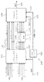
図1及び 図2は、実施例による3次元音声システムのアルゴリズムブロック図である。より詳細には、図1は3次元音声エンコーダ100の概略図である。前記音声エンコーダ100は、任意で設けられるプリレンダラ/ミキサー回路102において、入力信号、より詳細には、前記音声エンコーダ100に複数のチャネル信号104を入力する複数の入力チャネル、複数のオブジェクト信号106及び対応するオブジェクトメタデータ108を受信する。前記オブジェクト信号106は前記プリレンダラ/ミキサー102(信号110参照)により処理された後、SAOCエンコーダ112(SAOC:Spatial Audio Object Coding:空間音声オブジェクト符号化)に入力されてもよい。前記SAOCエンコーダ112は、USACエンコーダ116(USAC:Unified Speech and Audio Coding:発話音声統合符号化)の入力側に入力される前記SAOC伝送チャネル114を生成する。更に、SAOC−SI信号118(SAOC−SI:SAOC side information:サイド情報)も前記USACエンコーダ116の入力側に入力される。前記USACエンコーダ116は更に、オブジェクト信号120、並びに前記チャネル信号及びプリレンダリング済オブジェクト信号122を前記プリレンダラ/ミキサーから直接受信する。前記オブジェクトメタデータ情報108は、前記圧縮オブジェクトメタデータ情報126を前記USACエンコーダに入力するOAMエンコーダ124(OAM:object metadata:オブジェクトメタデータ)に適用される。前記USACエンコーダ116は、上記入力信号に基づき、128に示す圧縮出力信号MP4を生成する。
1 and 2 are algorithm block diagrams of a three-dimensional sound system according to an embodiment. More specifically, FIG. 1 is a schematic diagram of a three-
図2は、前記3次元音声システムの3次元音声デコーダ200の概略図である。図1の前記音声エンコーダ100により生成される前記符号化信号128(MP4)は、前記音声デコーダ200、より詳細にはUSACデコーダ202で受信される。前記USACデコーダ202は前記受信した信号128をチャネル信号204、プリレンダリング済オブジェクト信号206、オブジェクト信号208、及びSAOC伝送チャネル信号210に復号する。更に、圧縮オブジェクトメタデータ情報212及びSAOC−SI信号214が前記USACデコーダにより出力される。前記オブジェクト信号208は、レンダリング済オブジェクト信号218を出力するオブジェクトレンダラ216に入力される。前記SAOC伝送チャネル信号210はレンダリング済オブジェクト信号222を出力するSAOCデコーダ220に入力される。圧縮オブジェクトメタ情報212は、各制御信号を、前記レンダリング済オブジェクト信号218及び前記レンダリング済オブジェクト信号222を生成する前記オブジェクトレンダラ216及び前記SAOCデコーダ220に出力するOAMデコーダ224に入力される。前記デコーダは更に、図2に示すように、前記入力信号204、206、218及び222を受信してチャネル信号228を出力するためのミキサー226を備える。前記チャネル信号は、230に示す32チャネルラウドスピーカ等のラウドスピーカに直接出力されてもよい。また、前記信号228は、前記チャネル信号228が変換される経路を示す再生レイアウト信号を制御入力として受信するフォーマット変換回路232に入力されてもよい。図2に記載の実施例において、変換は信号を234に示す5.1スピーカシステムに入力可能な方法で行われるものする。また、前記チャネル信号228は、例えば238に示すヘッドフォン等を対象として2個の出力信号を生成するバイノーラル・レンダラ236に入力される。
FIG. 2 is a schematic diagram of a
図1及び図2に記載の前記符号化/復号化システムは、チャネル信号及びオブジェクト信号(信号104及び106参照)を符号化するためのMPEG−DUSACコーデックを基礎としていてもよい。大容量オブジェクトの符号化効率を向上させるため、MPEG SAOC技術を用いてもよい。三種類のレンダラにより、オブジェクトのチャネルへのレンダリング、チャネルのヘッドフォンへのレンダリング、又はチャネルの異なるラウドスピーカシステム(図2の参照番号230、234及び238参照)へのレンダリングを行ってもよい。オブジェクト信号がSAOCを用いて明示的に伝送、又はパラメトリックに符号化される場合、対応するオブジェクトメタデータ情報108は3次元音声ビットストリーム128に圧縮(信号126参照)及び多重化される。
The encoding / decoding system described in FIGS. 1 and 2 may be based on an MPEG-DUDAC codec for encoding channel signals and object signals (see
図1及び図2は、以下に更に詳細に説明する前記3次元音声システム全体のアルゴリズムブロック図を示す。 1 and 2 show algorithm block diagrams of the entire three-dimensional audio system, which will be described in more detail below.
図前記プリレンダラ/ミキサー102を任意で設けて、符号化前にチャネル+オブジェクト入力シーンをチャネルシーンに変換してもよい。前記装置は、後に詳述するオブジェクトレンダラ/ミキサーと機能的に同一である。オブジェクトのプリレンダリングは、基本的に同時にアクティブなオブジェクト信号数の影響を受けないエンコーダ入力における決定論的信号エントロピーを確保するために行われてもよい。オブジェクトをプリレンダリングする際、オブジェクトメタデータの伝送は不要である。離散オブジェクト信号は、前記エンコーダが使用するようするよう構成されるチャネルレイアウトにレンダリングされる。各チャネルに対するオブジェクトの重みは関連オブジェクトメタデータ(OAM)から得られる。
In the figure, the pre-renderer /
前記USACエンコーダ116は、ラウドスピーカ−チャネル信号、離散オブジェクト信号、オブジェクトダウンミックス信号及びプリレンダリング済信号のコアコーデックである。前記装置はMPEG−DUSAC技術を基礎としている。前記装置は、入力チャネル割当及びオブジェクト割当の幾何学的情報及びセマンティクス情報に基づいてチャネル及びオブジェクトマッピング情報を作成することにより上記信号の符号化処理を行う。前記マッピング情報は、入力チャネル及びオブジェクトがチャネル・ペア・エレメント(CPE)、シングル・チャネル・エレメント(SCE)、低域効果(LFE)及びチャネル・クワッド・エレメント(QCE)等のUSACチャネルエレメントにどのようにマッピングされるかを記述し、CPE、SCE、LFE、及び対応する情報は前記デコーダに伝送される。SAOCデータ114、118又はオブジェクトメタデータ126等の付加ペイロードは全てエンコーダ・レート制御にて考慮される。オブジェクトの符号化は、レンダラが求めるレート/歪み条件、及び双方向性条件に応じて、異なる経路で行うことも可能である。実施例によれば、以下のようなオブジェクト符号化も可能である。
・プリレンダリング済オブジェクト:オブジェクト信号は22.2チャネル信号にプリレンダリング及びミキシングされた後、符号化される。続く符号化チェーンでは22.2チャネル信号として処理される。
・離散オブジェクト波形:オブジェクトはモノラル波形としてエンコーダに入力される。エンコーダはシングル・チャネル・エレメント(SCE)を用いてチャネル信号及びオブジェクトを伝送する。復号化オブジェクトは受信側でレンダリング及びミキシングされる。圧縮オブジェクトメタデータ情報は受信装置/レンダラに伝送される。
・パラメトリックオブジェクト波形:オブジェクト特性及び相関性はSAOCパラメータにより記述する。オブジェクト信号のダウンミックスはUSACにより符号化される。パラメトリック情報も併せて伝送される。ダウンミックスチャネル数はオブジェクト数及び総データレートに応じて選択される。圧縮オブジェクトメタデータ情報はSAOCレンダラに伝送される。
The
Pre-rendered object : The object signal is pre-rendered and mixed into a 22.2 channel signal and then encoded. In the subsequent encoding chain, it is processed as a 22.2 channel signal.
Discrete object waveform : The object is input to the encoder as a monaural waveform. The encoder uses a single channel element (SCE) to transmit channel signals and objects. The decrypted object is rendered and mixed at the receiver. The compressed object metadata information is transmitted to the receiving device / renderer.
Parametric object waveform : Object characteristics and correlation are described by SAOC parameters. The downmix of the object signal is encoded by USAC. Parametric information is also transmitted. The number of downmix channels is selected according to the number of objects and the total data rate. The compressed object metadata information is transmitted to the SAOC renderer.
オブジェクト信号の前記SAOCエンコーダ112及び前記SAOCデコーダ220は、MPEG SAOC技術に基づくものでもよい。前記システムは、複数の音声オブジェクトをより少ない数の伝送チャネル、及びOLD、lOC(Inter Object Coherence:オブジェクト間コヒーレンス)、DMG(ダウンミックスゲイン)等の付加パラメトリックデータに基づき、再現、変更、及びレンダリングすることが可能である。当該付加パラメトリックデータのデータレートは、全オブジェクトを個別に伝送する際に必要となるレートに比べて非常に低く、符号化効率が向上する。前記SAOCエンコーダ112にはモノラル波形としてのオブジェクト/チャネル信号が入力され、(前記3次元音声ビットストリーム128にパケット化される)パラメトリック情報及び(シングル・チャネル・エレメントを用いて符号化及び伝送される)SAOC伝送チャネルを出力する。前記SAOCデコーダ220は、前記復号済SAOC伝送チャネル210及び前記パラメトリック情報214からオブジェクト/チャネル信号を再構築し、再生レイアウト、展開オブジェクトメタデータ情報、及び任意でユーザ・インタラクション情報に基づいて出力音声シーンを生成する。
The
オブジェクトメタデータ・コーデック(OAMエンコーダ124及びOAMデコーダ224参照)は、各オブジェクトについてオブジェクト特性を時間及び空間について量子化することにより、3次元空間におけるオブジェクトの幾何学的位置及び量を指定する関連メタデータを効率的に符号化することを目的としている。圧縮オブジェクトメタデータcOAM126は、サイド情報として前記受信装置200に伝送される。
The object metadata codec (see
前記オブジェクトレンダラ216は、圧縮オブジェクトメタデータを利用して所定の再生フォーマットでオブジェクト波形を生成する。各オブジェクトは自身のメタデータに基づき所定の出力チャネル218にレンダリングされる。当該ブロックの出力は部分結果が合計から成る。チャネルベースコンテンツ及び離散/パラメトリックオブジェクトが復号される場合、チャネルベース波形及びレンダリング済オブジェクト波形は前記ミキサー226によりミキシングされて、その後生成された波形228が出力される、又は前記バイノーラル・レンダラ236又は前記ラウドスピーカ・レンダラモジュール232等のポストプロセッサ/後処理系モジュールに入力される。
The
前記バイノーラル・レンダラモジュール236は、各入力チャネルが仮想音源により表現されるよう、マルチチャネル音声素材のバイノーラルダウンミックスを生成する。当該処理は、QMF(Quadrature Mirror Filterbank:直交ミラーフィルターバンク)ドメインにおいてフレーム的に行われ、バイノーラル化は測定されるバイノーラル室内インパルス応答に基づいて行われる。
The
前記ラウドスピーカ・レンダラ232は、送信された前記チャネル設定228と任意の再生フォーマットとの間の変換を行う。前記装置は「フォーマット変換装置」と呼称してもよい。前記フォーマット変換装置は、より少ない出力チャネル数への変換、すなわち、ダウンミックス作成を行う。
The
図3は、フォーマット変換装置232の実施例を示す。本発明の実施例において、前記信号処理装置は以下のようなフォーマット変換装置である。また、前記フォーマット変換装置232は、送信器(入力)チャネル設定の送信器(入力)チャネルを任意の再生フォーマット(出力チャネル設定)の(出力)チャネルにマッピングすることにより、送信器チャネル設定及び任意の再生フォーマット間で変換を行うラウドスピーカ・レンダラと呼称してもよい。一般的に、前記フォーマット変換装置232はより少ない出力チャネル数への変換、すなわち、ダウンミックス(DMX)工程240を行う。好ましくはQMFドメインにおいて動作する前記ダウンミキサー240は、前記ミキサー出力信号228を受信し、前記ラウドスピーカ信号234を出力する。コントローラとも呼称するコンフィギュレータ242を備えていてもよく、前記コンフィギュレータ242は、ミキサー出力レイアウト(入力チャネル設定)を表す信号246を制御入力として受信、すなわち、前記ミキサー出力信号228により表現されるデータのレイアウトを決定し、更に任意の再生レイアウト(出力チャネル設定)を表す信号248を受信する。当該情報に基づき、前記コントローラ242は所定の組合せによる入出力フォーマットのためのダウンミックスマトリクスを好ましくは自動的に生成し、当該マトリクスを前記ダウンミキサー240に適用する。前記フォーマット変換装置232は、標準ラウドスピーカ設定及び非標準ラウドスピーカ配置によるランダム設定を可能にする。
FIG. 3 shows an embodiment of the
本発明の実施例は、前記ラウドスピーカ・レンダラ232の実施例、すなわち前記ラウドスピーカ・レンダラ232の機能性の一部を実現するための装置及び方法に関する。
Embodiments of the present invention relate to embodiments of the
図4及び図5を参照する。図4は5.1フォーマットを表現するラウドスピーカ設定を示し、左チャネルLC、中央チャネルCC、右チャネルRC、左サラウンドチャネルLSC、右サラウンドチャネルLRC、及び低周波数エンハンスメントチャネルLFCを表現する6個のラウドスピーカを備える。図5は別のラウドスピーカ設定を示し、左チャネルLC、中央チャネルCC、右チャネルRC、及び上方中央チャネルECCを表現するラウドスピーカを備える。 Please refer to FIG. 4 and FIG. FIG. 4 shows a loudspeaker configuration that represents the 5.1 format, six channels representing a left channel LC, a center channel CC, a right channel RC, a left surround channel LSC, a right surround channel LRC, and a low frequency enhancement channel LFC. A loudspeaker is provided. FIG. 5 shows another loudspeaker setting, comprising a loudspeaker that represents a left channel LC, a center channel CC, a right channel RC, and an upper center channel ECC.
以下において、前記低周波数エンハンスメントチャネルに関連付けされたラウドスピーカ(サブウーファ)の正確な配置は重要ではないため、低周波数エンハンスメントチャネルについては考慮していない。 In the following, the exact placement of the loudspeakers (subwoofers) associated with the low frequency enhancement channel is not important, so the low frequency enhancement channel is not considered.
前記チャネルの各々は、前記中央のリスナー位置Pに対して特定の方向に配置される。図5に示す通り、各チャネルの方向は方位角α及び仰角βにより定義する。方位角はリスナー水平面300におけるチャネル角度を表し、前中央方向302に対する各チャネルの方向としてもよい。図4に示す通り、前記前中央方向302は、前記中央のリスナー位置Pに位置するリスナーの通常の視聴方向と定義してもよい。後中央方向304は、前記前中央方向300に対して180°の方位角を有する。前中央方向の左側における前中央方向と後中央方向との間の全方位角は前中央方向の左側に位置し、前中央方向の右側における前中央方向と後中央方向との間の全方位角は前中央方向の右側に位置する。前記前中央方向302に対して直角であり中央のリスナー位置Pを通過する仮想線306の前方に位置するラウドスピーカは前方ラウドスピーカであり、仮想線306の後方に位置するラウドスピーカは後方ラウドスピーカである。5.1フォーマットにおいて、前記方位角αはチャネルLCが左方向に30°、CCが0°、RCが右方向に30°、LSCが左方向に110°、そしてRSCが右方向に110°である。
Each of the channels is arranged in a specific direction with respect to the central listener position P. As shown in FIG. 5, the direction of each channel is defined by an azimuth angle α and an elevation angle β. The azimuth angle represents the channel angle in the listener
チャネルの前記仰角βは、前記リスナー水平面300と、中央のリスナー位置と各チャネルに関連付けされたラウドスピーカの間の仮想接続線の方向との間の角度を定義する。図4に示す設定において、全ラウドスピーカは前記リスナー水平面300内に配置されるため、仰角は全てゼロである。図5において、チャネルECCの仰角βは30°であってもよい。前記中央のリスナー位置の真上に位置するラウドスピーカの仰角は90°となる。前記リスナー水平面300の下方に配置されるラウドスピーカの仰角は負角となる。図5において、LCは方向x1,CCは方向x2、RCは方向x3、ECCは方向x4をそれぞれ有する。
The elevation angle β of the channel defines the angle between the listener
空間における特定のチャネルの配置、すなわち特定のチャネルに関連付けされたラウドスピーカ配置)は方位角、仰角及び中央のリスナー位置からのラウドスピーカまでの距離により決定される。なお、「ラウドスピーカの配置」という語は、多くの場合、当業者により方位角および仰角のみを参照して記述される。 The placement of a particular channel in space, i.e. the loudspeaker placement associated with a particular channel, is determined by the azimuth, elevation and distance from the central listener position to the loudspeaker. Note that the term “arrangement of loudspeakers” is often described by those skilled in the art with reference to only the azimuth and elevation.
一般に、異なるラウドスピーカチャネル設定間のフォーマット変換は、複数の入力チャネルを複数の出力チャネル数にマッピングするダウンミックス処理として実行され、その際、出力チャネル数は通常入力チャネル数より少なく、出力チャネル配置は入力チャネル配置と異なっていてもよい。1個以上の入力チャネルが同一の出力チャネルにミキシングされてもよい。同時に、1個以上の入力チャネルが2個以上の出力チャネルに対してレンダリングされてもよい。当該入力チャネルから出力チャネルへのマッピングは通常1組のダウンミックス係数により決定される(又はダウンミックスマトリクスとして定式化される)。ダウンミックス係数の選択は、得られるダウンミックス出力音質に大きく影響する。選択を誤った場合、ミキシングが不均衡になったり、入力音声シーンの空間的再生が低品質となることも考えられる。 In general, format conversion between different loudspeaker channel settings is performed as a downmix process that maps multiple input channels to multiple output channel numbers, where the number of output channels is usually less than the number of input channels and the output channel arrangement May be different from the input channel arrangement. One or more input channels may be mixed into the same output channel. At the same time, one or more input channels may be rendered for two or more output channels. The mapping from the input channel to the output channel is usually determined by a set of downmix coefficients (or formulated as a downmix matrix). The selection of the downmix coefficient greatly affects the resulting downmix output sound quality. If the selection is wrong, mixing may be unbalanced, or the spatial reproduction of the input audio scene may be of low quality.
各チャネルは、対応するラウドスピーカにより再生される音声信号に関連付けされる。特定のチャネル(係数の適用、等化フィルタの適用、又は非相関フィルタの適用等により)が処理されるということは、当該チャネルに関連付けされた対応する音声信号が処理されるということを意味する。本出願のコンテクストにおいては、「等化フィルタ」という語は、信号成分の周波数依存な重み付けが可能となるよう信号を等化する手段の全てを包含することを意図している。例えば、等化フィルタは、周波数依存ゲイン係数を信号の周波数帯に適用するよう構成されてもよい。本出願のコンテクストにおいては、「非相関フィルタ」という語は、周波数依存な遅延及び/又はランダム化フェーズを信号に導入すること等により信号を非相関化する手段の全てを包含することを意図している。例えば、非相関フィルタは周波数依存な遅延係数を信号の周波数帯適用するよう、及び/又はランダム化フェーズ係数を信号に適用するよう構成されてもよい。 Each channel is associated with an audio signal that is played by a corresponding loudspeaker. Processing a particular channel (such as applying a coefficient, applying an equalization filter, or applying a decorrelation filter, etc.) means that the corresponding audio signal associated with that channel is processed. . In the context of this application, the term “equalization filter” is intended to encompass all means of equalizing a signal so that frequency-dependent weighting of signal components is possible. For example, the equalization filter may be configured to apply a frequency dependent gain factor to the frequency band of the signal. In the context of this application, the term “decorative filter” is intended to encompass all means of decorrelating a signal, such as by introducing a frequency dependent delay and / or randomization phase into the signal. ing. For example, the decorrelation filter may be configured to apply a frequency dependent delay coefficient to the signal's frequency band and / or to apply a randomized phase coefficient to the signal.
本発明の実施例において、入力チャネルを少なくとも1個の出力チャネルにマッピングする方法は、入力チャネルがマッピングされる出力チャネルの各々に対して入力チャネルに適用される少なくとも1個の係数を適用する工程を含む。当該少なくとも1個の係数は、入力チャネルに関連付けされた入力信号に適用されるゲイン係数、すなわちゲイン値、及び/又は入力チャネルに関連付けされた入力信号に適用される遅延係数、すなわち遅延値を含んでいてもよい。本発明の実施例において、マッピング方法は周波数選択的係数、すなわち入力チャネルの異なる周波数帯に対し異なる係数を適用する工程を含んでいてもよい。本発明の実施例において、入力チャネルを出力チャネルにマッピングする方法は、係数から少なくとも1個の係数マトリクスを生成する工程を含む。各マトリクスは、出力チャネル設定の各出力チャネルに対して入力チャネル設定の各入力チャネルに適用される係数を定義する。入力チャネルがマッピングされない出力チャネルについては、係数マトリクスにおける各係数はゼロとなる。本発明の実施例において、ゲイン係数及び遅延係数に対して個別に係数マトリクスを生成してもよい。本発明の実施例において、各周波数帯に対して係数が周波数選択的な係数マトリクスを生成してもよい。本発明の実施例において、マッピング方法は更に、導出された係数を入力チャネルに関連付けされた入力信号に適用する工程を備えていてもよい。 In an embodiment of the present invention, a method for mapping an input channel to at least one output channel comprises applying at least one coefficient applied to the input channel for each output channel to which the input channel is mapped. including. The at least one coefficient includes a gain factor applied to an input signal associated with the input channel, i.e., a gain value, and / or a delay coefficient applied to the input signal associated with the input channel, i.e., a delay value. You may go out. In an embodiment of the present invention, the mapping method may include applying frequency selective coefficients, i.e. different coefficients for different frequency bands of the input channel. In an embodiment of the present invention, a method for mapping an input channel to an output channel includes generating at least one coefficient matrix from the coefficients. Each matrix defines a coefficient applied to each input channel of the input channel setting for each output channel of the output channel setting. For output channels to which no input channel is mapped, each coefficient in the coefficient matrix is zero. In the embodiment of the present invention, the coefficient matrix may be generated individually for the gain coefficient and the delay coefficient. In an embodiment of the present invention, a coefficient matrix in which the coefficients are frequency selective may be generated for each frequency band. In an embodiment of the present invention, the mapping method may further comprise the step of applying the derived coefficients to the input signal associated with the input channel.
良好なダウンミックス係数を得るため、専門家(音響技師等)は、自己の専門技術に基づき手作業で係数を調整する場合もある。他の選択肢として、各入力チャネルを、その空間内の配置が特定のチャネルに関連付けされた空間内の配置、すなわち特定の入力チャネルに関連付けされたラウドスピーカ配置により決定される仮想音源として処理することにより、入出力設定の所定の組合せに対してダウンミックス係数を自動的に導出する方法が考えられる。各仮想音源は、2次元における正接定理パニング、又は3次元におけるベクトル式振幅パニング(BVAP)(V.プルッキ(Pulkki):「ベクトル式振幅パニングを用いた仮想音源配置方法(Virtual Sound Source Positioning Using Vector Base Amplitude Panning)」、音声技術学会誌(Journal of the Audio Engineering Society)、45巻、456〜466頁、1997年参照)等の一般的パニングアルゴリズムにより再生してもよい。入出力チャネル設定の所定の組合せに対してダウンミックス係数を数学的、すなわち自動的に導出する別の方法としては、安藤彰男による「再生音場における音声の物理的特性を維持するマルチチャネル音声信号の変換」、IEEE音声・言語音声・言語処理会報(IEEE Transactions on Audio、Speech、and Language Processing)、19巻、6号、2011年8月に提言されている。 To obtain a good downmix coefficient, a specialist (acoustic engineer, etc.) may manually adjust the coefficient based on his / her own expertise. Another option is to treat each input channel as a virtual sound source determined by the arrangement in the space whose placement in that space is associated with a particular channel, ie the loudspeaker placement associated with the particular input channel. Thus, a method of automatically deriving a downmix coefficient for a predetermined combination of input / output settings can be considered. Each virtual sound source is represented by two-dimensional tangent theorem panning, or three-dimensional vector-type amplitude panning (BVAP) (V. Pulkki: “Virtual Sound Source Positioning Using Vectoring Amplitude Panning” It may be reproduced by a general panning algorithm such as “Base Amplitude Panning”, Journal of the Audio Engineering Society, Vol. 45, pp. 456-466 (1997). Another way to derive the downmix coefficients mathematically, ie automatically, for a given combination of input and output channel settings, is the multichannel audio signal that maintains the physical characteristics of the audio in the playback sound field. ”, IEEE Transactions on Audio, Speech, and Language Processing, Vol. 19, No. 6, August 2011.
したがって、既存のダウンミックス手法は、主にダウンミックス係数を導出するための3種類の手法に基づいている。第一の手法は、破棄された入力チャネルを同一又は同等な方位角位置で出力チャネルに直接マッピングするものである。仰角オフセットは、無視される。例えば、一般的な方法として、高位レイヤが出力チャネル設定において存在しない場合、上方チャネルを同一又は同等な方位角位置の水平面チャネルに直接レンダリングする。第二の手法は、一般的パニングアルゴリズムを用いて、入力チャネルを仮想音源として処理し、ファントム音源を破棄された入力チャネルの配置で導入することにより方位角情報を保持するものである。仰角オフセットは、無視される。最先端の方法においては、パニングは、求める出力配置、例えば、求める方位角において使用可能な出力ラウドスピーカが存在しない場合のみ使用される。第三の手法は、専門技術を組込むことにより、経験的、芸術的又は心理音響的感覚において、最適なダウンミックス係数を導出するものである。異なる手法を個別に用いてもよく、又は組合せて適用してもよい。 Therefore, the existing downmix technique is mainly based on three kinds of techniques for deriving the downmix coefficient. The first technique is to directly map the discarded input channel to the output channel at the same or equivalent azimuth position. The elevation offset is ignored. For example, as a general practice, if no higher layer is present in the output channel setting, the upper channel is rendered directly into the horizontal plane channel at the same or equivalent azimuthal position. The second method uses a general panning algorithm to process an input channel as a virtual sound source, and to introduce phantom sound sources with the discarded input channel arrangement to hold azimuth information. The elevation offset is ignored. In state-of-the-art methods, panning is used only when there is no output loudspeaker available at the desired output configuration, eg, the desired azimuth angle. The third method is to derive an optimal downmix coefficient in an empirical, artistic or psychoacoustic sense by incorporating specialized techniques. Different approaches may be used individually or in combination.
本発明の実施例は、ダウンミックス処理を向上又は最適化することにより、当該システムを使用しない場合に比べて、より高いダウンミックス品質の出力信号が得られる技術システムを提供する。実施例において、前記システムは、提案する前記システムを適用せずに行ったダウンミックスの最中に入力チャネル設定に固有な空間多様性が喪失するような場合に、ダウンミックス品質を向上させることが可能となる。 Embodiments of the present invention provide a technical system that improves or optimizes the downmix process to provide an output signal with a higher downmix quality than when the system is not used. In an embodiment, the system may improve the downmix quality when the spatial diversity inherent in the input channel configuration is lost during the downmix performed without applying the proposed system. It becomes possible.
そのために、本発明の実施例により、入力チャネル設定に固有で直接的なダウンミックス(DMX)手法では保持されない空間多様性の保持が可能となる。本発明の実施例は、音響チャネル数が減少するダウンミックスシナリオにおいて、より高いチャネル数からより低いチャネル数へのマッピングを行うと黙示的に発生する多様性及び包込み(envelopment)の喪失を軽減することを主な目的としている。 For this reason, according to the embodiment of the present invention, it is possible to maintain the spatial diversity that is unique to the input channel setting and is not maintained by the direct downmix (DMX) technique. Embodiments of the present invention mitigate the loss of diversity and envelope that occurs implicitly when mapping from higher to lower channels in a downmix scenario where the number of acoustic channels is reduced. The main purpose is to do.
発明者らは、特定の設定によっては、入力チャネル設定の固有な空間多様性及び空間的包込み(envelopment)は、多くの場合、出力チャネル設定において大幅に低下、又は完全に喪失する点に気付いた。更に、入力設定における複数のスピーカからの聴覚事象は、同時に再生されると、出力設定において、よりコヒーレントで凝縮及び集中したものとなる。これにより、空間的印象が知覚的により圧迫したものとなり、多くの場合、入力チャネル設定に比べて魅力が失われるということが発生する場合がある。本発明の実施例の目的は、出力チャネル設定における空間多様性を初めて明確に保持しようとするものである。本発明の実施例は、聴覚事象の知覚される位置を元の入力チャネルラウドスピーカ設定を用いた場合と比較してできる限り近く保持することを目的とする。 The inventors have noticed that, depending on the particular setting, the inherent spatial diversity and spatial inclusion of the input channel setting is often significantly reduced or completely lost in the output channel setting. It was. In addition, auditory events from multiple speakers at the input setting are more coherent and condensed and concentrated at the output setting when played back simultaneously. This makes the spatial impression more perceptually squeezed and in many cases may be less attractive than the input channel setting. The purpose of the embodiments of the present invention is to first clearly maintain the spatial diversity in the output channel setting. Embodiments of the present invention aim to keep the perceived position of an auditory event as close as possible compared to using the original input channel loudspeaker settings.
したがって、本発明の実施例は、入力チャネル設定の異なるラウドスピーカ配置に関連付けされるため、空間多様性を備える第1の入力チャネル及び第2の入力チャネルを、少なくとも1個の出力チャネルにマッピングするための特定の手法を提供する。本発明の実施例において、前記第1の入力チャネル及び第2の入力チャネルは、リスナー水平面に対してそれぞれ異なる仰角をとる。したがって、出力チャネル設定のラウドスピーカを用いた音声再生を向上させるために、前記第1の入力チャネルと前記第2の入力チャネルとの間の仰角オフセットが考慮されてもよい。 Therefore, embodiments of the present invention are associated with loudspeaker arrangements with different input channel settings, so that the first input channel and the second input channel with spatial diversity are mapped to at least one output channel. Providing a specific method for In an embodiment of the present invention, the first input channel and the second input channel have different elevation angles with respect to the listener horizontal plane. Therefore, an elevation offset between the first input channel and the second input channel may be considered in order to improve audio reproduction using a loudspeaker with an output channel setting.
本出願のコンテクストにおいては、多様性は、以下のように説明できる。入力チャネル設定の別々のラウドスピーカが、ラウドスピーカから位置Pに位置するリスナーの両耳等の耳への別々の音響チャネルとして生成される。また、聴取する部屋の多様な励振から発生し、異なるラウドスピーカ配置から知覚される信号の非相関化及び音質変化の原因となる反射音又は反響音としても知られる直接的音響経路及び間接的音響経路が存在する。BRIRによれば、各聴取する部屋に特有の音響チャネルを完全に形成できる。入力チャネル設定の聴取経験は、特定のラウドスピーカ配置に対応する個々の入力チャネルと多様なBRIRとの特有の組合せに大きく依存する。したがって、多様性及び包込み(envelopment)は、聴取する部屋により本質的に全ラウドスピーカ信号に与えられる多様性な信号変形から生じる。 In the context of this application, diversity can be explained as follows. Separate loudspeakers with input channel settings are generated as separate acoustic channels from the loudspeakers to the ears, such as the listener's binaural located at position P. Direct acoustic paths and indirect acoustics, also known as reflected or reverberant sounds, that arise from various excitations in the listening room and cause signal decorrelation and sound quality changes perceived from different loudspeaker arrangements A route exists. According to BRIR, an acoustic channel specific to each listening room can be completely formed. The listening experience of the input channel settings is highly dependent on the unique combination of individual input channels and various BRIRs corresponding to a particular loudspeaker arrangement. Thus, diversity and envelope arise from the diverse signal deformations that are imparted to essentially all loudspeaker signals by the listening room.
以下に、入力チャネル設定の空間多様性を保持するダウンミックス手法の必要性を説明する。入力チャネル設定は、出力チャネル設定より多いラウドスピーカを使用していてもよく、又は出力ラウドスピーカ設定において存在しないラウドスピーカを少なくとも1個使用していてもよい。図5に説明のみを目的として示す通り、出力チャネル設定がラウドスピーカECCを除き、ラウドスピーカLC、CC及びRCのみを使用しているのに対し、入力チャネル設定がラウドスピーカLC、CC、RC、ECCを使用していてもよい。したがって、入力チャネル設定が出力チャネル設定よりも多い数の再生レイヤを使用していてもよい。例えば、出力設定が水平面のスピーカ(LC、CC、RC)のみを備える場合に、入力チャネル設定が水平面(LC、CC、RC)スピーカ及び高位(ECC)スピーカ両方を備えていてもよい。したがって、ダウンミックスにおいては、ラウドスピーカから両耳への音響チャネル数は、出力チャネル設定において減少する。詳細には、3次元(22.2等)から2次元(5.1等)へのダウンミックス(DMX)は、出力チャネル設定において個々の再生レイヤが欠如していることに最も影響を受ける。出力チャネル設定において多様性及び包込み(envelopment)に関して類似の聴取経験を実現する自由度が減少し、その結果限定される。本発明の実施例は、入力チャネル設定の空間多様性をより良く保持するダウンミックス手法を提供するが、記載する装置及び方法は、特定のダウンミックス手法に限定されず、様々なコンテクスト及びアプリケーションに適用できる。 In the following, the necessity of a downmix technique that preserves the spatial diversity of input channel settings will be described. The input channel settings may use more loudspeakers than the output channel settings, or may use at least one loudspeaker that does not exist in the output loudspeaker settings. As shown in FIG. 5 for illustrative purposes only, the output channel setting uses only the loudspeakers LC, CC, and RC except for the loudspeaker ECC, whereas the input channel setting is the loudspeaker LC, CC, RC, ECC may be used. Therefore, a larger number of playback layers may be used for input channel settings than for output channel settings. For example, if the output setting comprises only horizontal (LC, CC, RC) speakers, the input channel setting may comprise both horizontal (LC, CC, RC) and high level (ECC) speakers. Therefore, in the downmix, the number of sound channels from the loudspeaker to both ears decreases at the output channel setting. Specifically, downmixing (DMX) from three dimensions (such as 22.2) to two dimensions (such as 5.1) is most affected by the lack of individual playback layers in the output channel settings. The degree of freedom to achieve a similar listening experience in terms of diversity and envelope in output channel settings is reduced and consequently limited. While embodiments of the present invention provide a downmix technique that better preserves the spatial diversity of input channel settings, the described apparatus and method are not limited to a particular downmix technique, and can be used in a variety of contexts and applications. Applicable.
以下において、本発明の実施例を図5に記載の特定のシナリオを参照して説明する。但し、記載される問題及びシステムは類似条件を伴う別のシナリオに容易に適用可能である。一般性を失うことなく、入力及び出力チャネル設定を以下のように仮定する。 In the following, embodiments of the present invention will be described with reference to a specific scenario described in FIG. However, the problems and systems described are readily applicable to other scenarios with similar conditions. Without loss of generality, the input and output channel settings are assumed as follows:
入力チャネル設定:x1=(α1,β1)、x2=(α2,β1)、x3=(α3,β1)及びx4=(α4,β2)に配置される4個のラウドスピーカLC,CC、RC、及びECC、ここでα2≒α4又はα2=α4。 Input channel settings: arranged at x 1 = (α 1 , β 1 ), x 2 = (α 2 , β 1 ), x 3 = (α 3 , β 1 ) and x 4 = (α 4 , β 2 ) Four loudspeakers LC, CC, RC, and ECC, where α 2 ≈α 4 or α 2 = α 4 .
出力チャネル設定:x1=(α1,β1)、x2=(α2,β1)、x3=(α3,β1)に配置される3個のラウドスピーカ、すなわちx4に配置されるラウドスピーカは、ダウンミックスにより破棄される。αは、前記方位角を表し、βは、仰角を表す。 Output channel settings: 3 loudspeakers arranged at x 1 = (α 1 , β 1 ), x 2 = (α 2 , β 1 ), x 3 = (α 3 , β 1 ), ie x 4 The arranged loudspeaker is discarded by the downmix. α represents the azimuth angle, and β represents the elevation angle.
上記したように、直接的なDMX手法は、指向性の方位角情報の保持をを優先し、仰角オフセットは、全て無視する。したがって、x4に配置されるラウドスピーカECCからの信号は、単純にx2に配置されるラウドスピーカCCに送られる。但し、その際、特性が喪失する。第一に、再生配置x2及びx4において本質的に適用されるBRIRが異なることによる音質差が喪失する。第二に、異なる配置x2及びx4で再生される入力信号の空間多様性が喪失する。第三に、配置x2及びx4からリスナーの両耳までの音響伝播経路が異なることによる入力信号の固有な非相関性が喪失する。 As described above, the direct DMX method gives priority to the retention of directivity azimuth information and ignores all elevation angle offsets. Thus, the signal from the loudspeaker ECC disposed x 4 is sent simply loudspeaker CC arranged in x 2. However, at that time, the characteristics are lost. First, the sound quality difference due to the difference in the BRIR applied essentially in the reproduction arrangements x 2 and x 4 is lost. Second, the spatial diversity of the input signal reproduced with different arrangements x 2 and x 4 is lost. Third, the inherent decorrelation of the input signal is lost due to the different acoustic propagation paths from the placements x 2 and x 4 to the listener's ears.
本発明の実施例は、ダウンミックス処理に対して本明細書に記載の手法を個別に又は組合せて適用することにより、上記の特性のうち少なくとも1個を保持又は維持することを目的とする。 Embodiments of the present invention aim to retain or maintain at least one of the above characteristics by applying the techniques described herein individually or in combination to the downmix process.
図6A及び図6Bは、一手法を実現するための装置10を説明するための概略図を示し、この場合、第1の入力チャネル12及び第2の入力チャネル14が同一の出力チャネル16にマッピングされるが、その際、前記第2の入力チャネルの処理は、等化フィルタ及び非相関フィルタのうちいずれかを前記第2の入力チャネルに適用することにより行われる。図6Aにおいて、当該処理は、ブロック18で示す。
6A and 6B show a schematic diagram for describing an
本出願において説明及び説明する装置は、記載の機能性を得るよう構成及び/又はプログラムされる各コンピュータ又はプロセッサにより実現されてもよいことは当業者にとって明らかである。また、前記装置は、フィールド・プログラマブル・ゲートアレイ等の別のプログラムハードウェア構造体として実現構成されていてもよい。 It will be apparent to those skilled in the art that the devices described and described in this application may be implemented by each computer or processor configured and / or programmed to obtain the described functionality. The apparatus may be realized and configured as another program hardware structure such as a field programmable gate array.
図6Aに記載の前記第1の入力チャネル12はx2方向に配置される中央ラウドスピーカCCに関連付けされてもよく、前記第2の入力チャネル14はx4に配置される上方中央ラウドスピーカECCに関連付けされてもよい(各々入力チャネル設定において)。前記出力チャネル16は、x2に配置される中央ラウドスピーカECCに関連付けされてもよい(出力チャネル設定において)。図6Bにおいて、x4に配置されるラウドスピーカに関連付けされたチャネル14は、x2に配置されるラウドスピーカCCに関連付けされた前記第1の出力チャネル16にマッピングされ、当該マッピングは、前記第2の入力チャネル14を処理するステップ18、すなわち第2の入力チャネル14に関連付けされた音声信号を処理するステップを備える。前記第2の入力チャネルを処理するステップは、等化フィルタ及び非相関フィルタのいずれかを前記第2の入力チャネルに適用することにより、入力チャネル設定において前記第1の入力チャネルと前記第2の入力チャネルとの間で異なる特性を保持するステップを備える。実施例において、前記等化フィルタ及び/又は前記非相関フィルタは、第1の入力チャネル及び第2の入力チャネルに関連付けされた異なるラウドスピーカ配置x2及びx4において本質的に適用される異なるBRIRによる音質差に関する特性を保持するよう構成されてもよい。本発明の実施例において、前記等化フィルタ及び/又は前記非相関フィルタは、前記第1の入力チャネル及び前記第2の入力チャネルが同一の出力チャネルにマッピングされる場合にも、前記第1の入力チャネル及び前記第2の入力チャネルの空間多様性が知覚可能な状態に保持されるよう別々な配置で再生される入力信号の空間多様性を保持するよう構成される。
The
本発明の実施例において、非相関フィルタは、前記第1の入力チャネル及び前記第2の入力チャネルに関連付けされた別々のラウドスピーカ配置からリスナーの両耳までの音響伝播経路が異なることによる入力信号に固有な非相関性を保持するよう構成される。 In an embodiment of the present invention, the decorrelation filter includes an input signal due to different acoustic propagation paths from separate loudspeaker arrangements associated with the first input channel and the second input channel to the listener's ears. Is configured to maintain the inherent decorrelation.
本発明の実施例において、等化フィルタは、前記第2の入力チャネル、すなわちx4に配置される前記第2の入力チャネルに関連付けされた音声信号がx2に配置される前記ラウドスピーカCCにダウンミックスされる場合、適用される。前記等化フィルタは、異なる音響チャネルの音質変化を補償し、経験的専門技術及び/又は計測したBRIR等に基づき導出されてもよい。例えば、前記入力チャネル設定が仰角90°において「天の声」(Voice of God:VoG)チャネルを備えると仮定する。5.1出力設定のように、前記出力チャネル設定が1層のレイヤのみにおいてラウドスピーカを備え、前記VoGチャネルが破棄される場合、少なくともスイート・スポットにおける前記VoGチャネルの方向情報を保持するために前記VoGチャネルを全出力ラウドスピーカに分配する手法は、単純で直接的である。しかしながら、BRIRが異なるために元のVoGラウドスピーカは、非常に異なって知覚される。全出力ラウドスピーカに分配する前に前記VoGチャネルに専用の等化フィルタを適用することにより、音質差を補償できる。 In an embodiment of the present invention, the equalization filter, said second input channel, i.e. the loudspeaker CC audio signal the is associated with a second input channels arranged in x 4 are arranged in x 2 Applied when downmixed. The equalization filter may be derived based on empirical expertise and / or measured BRIR, etc., to compensate for sound quality changes in different acoustic channels. For example, assume that the input channel configuration comprises a “Voice of God (VoG)” channel at an elevation angle of 90 °. To maintain direction information of the VoG channel at least in the sweet spot when the output channel configuration includes a loudspeaker in only one layer and the VoG channel is discarded as in 5.1 output configuration The technique of distributing the VoG channel to all output loudspeakers is simple and straightforward. However, because of the different BRIRs, the original VoG loudspeaker is perceived very differently. The sound quality difference can be compensated by applying a dedicated equalization filter to the VoG channel before distributing to all output loudspeakers.
本発明の実施例において、前記等化フィルタは、音声信号の方向知覚に関する心理音響的発見を考慮するため、対応する入力チャネルに周波数依存な重み付けを行うよう構成されてもよい。当該発見の一例として、方向決定する帯域を表現するいわゆるブラウエルト(Blauert)帯域が挙げられる。図12は、音声信号の特定の方向が認識される確率を表す3個のグラフ20、22及び24を示す。グラフ20に示す通り、上方からの音声信号は、周波数帯1200において7kHz〜10kHzで高い確率で認識される。グラフ22に示す通り、後方からの音声信号は、周波数帯1202において約0.7kHz〜約2kHz、及び周波数帯1204において約10kHz〜約12.5kHzで高い確率で認識される。グラフ24に示す通り、前方からの音声信号は、周波数帯1206において約0.3kHz〜0.6kHz、及び周波数帯1208において約2.5〜約5.5kHzで高い確率で認識される。
In an embodiment of the present invention, the equalization filter may be configured to perform frequency-dependent weighting on the corresponding input channel in order to take into account psychoacoustic discoveries regarding the direction perception of the audio signal. As an example of the discovery, there is a so-called Brauert band that represents a band for determining a direction. FIG. 12 shows three
本発明の実施例において、前記等化フィルタは、上記の認識性を用いて構成される。すなわち、等化フィルタは、別の周波数帯と比較して、音声が特定の方向から聞こえるような印象をユーザに与えると知られている周波数帯により高いゲイン係数(ブースト)を適用するよう構成されてもよい。より詳細には、入力チャネルがより低い出力チャネルにマッピングされる場合、対応する信号が上方の配置から発生している印象をリスナーに与えるために、入力チャネルの周波数帯1200における7kHz〜10kHzの範囲のスペクトル成分を前記第2の入力チャネルの別のスペクトル成分と比較してブーストしてもよい。同様に、図12に記載の通り、等化フィルタは、前記第2の入力チャネルの別のスペクトル成分をブーストするよう構成されてもよい。例えば、入力チャネルがより前方に配置される出力チャネルにマッピングされる場合に帯域1206及び帯域1208をブーストしてもよく、入力チャネルがより後方に配置される出力チャネルにマッピングされる場合に帯域1202及び帯域1204をブーストしてもよい。
In an embodiment of the present invention, the equalization filter is configured using the above recognition. That is, the equalization filter is configured to apply a higher gain factor (boost) to a frequency band known to give the user an impression that the sound can be heard from a particular direction compared to another frequency band. May be. More specifically, when the input channel is mapped to a lower output channel, a range of 7 kHz to 10 kHz in the input
本発明の実施例において、前記装置は、前記第2の入力チャネルに非相関フィルタを適用するよう構成される。例えば、x2に配置されるラウドスピーカにダウンミックスする場合、非相関/反響音フィルタを(x4に配置されるラウドスピーカに関連付けされた)前記第2の入力チャネルに関連付けされた入力信号に適用してもよい。当該非相関/反響音フィルタは、BRIR測定又は室内音響学等に関する経験的技術により導出されてもよい。入力チャネルが複数の出力チャネルにマッピングされる場合、前記複数のラウドスピーカに対してフィルタ信号を再生してもよく、その場合、各ラウドスピーカに対して異なるフィルタを適用してもよい。前記フィルタは、初期反射のみモデル化してもよい。 In an embodiment of the invention, the device is configured to apply a decorrelation filter to the second input channel. For example, when downmixing the loudspeakers arranged in the x 2, the decorrelation / reverberation filter (which is associated with a loudspeaker disposed in x 4) to the input signal associated with the second input channel You may apply. The decorrelation / resonance filter may be derived by empirical techniques such as BRIR measurements or room acoustics. When an input channel is mapped to a plurality of output channels, a filter signal may be reproduced for the plurality of loudspeakers, in which case a different filter may be applied to each loudspeaker. The filter may model only the initial reflection.
図8は、等化フィルタ又は非相関フィルタであってもよいフィルタ32を備える装置30の概略図である。前記装置30は、複数の入力チャネル34を受信し、複数の出力チャネル36を出力する。前記入力チャネル34は、入力チャネル設定を表現し、前記出力チャネル36は、出力チャネル設定を表現する。図8に記載の通り、第3の入力チャネル38、第2の出力チャネル42に直接マッピングされ、第4の入力チャネル40は、第3の出力チャネル44に直接マッピングされる。前記第3の入力チャネル38は、左ラウドスピーカLCに関連付けされた左チャネルであってもよい。前記第4の入力チャネル40は、右ラウドスピーカRCに関連付けされた右入力チャネルであってもよい。前記第2の出力チャネル42は、左ラウドスピーカLCに関連付けされた左チャネルであってもよく、前記第3の出力チャネル44は、右ラウドスピーカRCに関連付けされた右チャネルであってもよい。前記第1の入力チャネル12は、中央ラウドスピーカCCに関連付けされた中央水平面チャネルであってもよく、前記第2の入力チャネル14は、上方中央ラウドスピーカECCに関連付けされた上方中央チャネルであってもよい。フィルタ32は、前記第2の入力チャネル14、すなわち前記上方中央チャネルに適用される。前記フィルタ32は、非相関フィルタ又は反響音フィルタであってもよい。フィルタ後、前記第2の入力チャネルは、前記水平面中央ラウドスピーカ、すなわちx2に配置されるラウドスピーカCCに関連付けされた前記第1の出力チャネル16に送信される。したがって、図8のブロック46に示す通り、前記入力チャネル12及び入力チャネル14は、共に前記第1の出力チャネル16にマッピングされる。本発明の実施例において、ブロック46において前記第1の入力チャネル12及び処理済前記第2の入力チャネル14を付加し、出力チャネル16、すなわち本実施例の前記中央水平面ラウドスピーカCCに関連付けされたラウドスピーカに入力してもよい。
FIG. 8 is a schematic diagram of an
本発明の実施例において、フィルタ32は、2個の分離された音響チャネルが存在する場合に知覚される追加の室内空間効果(room effect)をモデル化するための非相関フィルタ又は反響音フィルタであってもよい。非相関化により、当該通知によりDMXキャンセルの中間生成物を軽減できる場合がある。本発明の実施例において、フィルタ32は、等化フィルタであってもよく、音質等化を実行するよう構成されてもよい。本発明の別の実施例において、上方ラウドスピーカの信号をダウンミックスする前に、非相関フィルタ及び反響音フィルタを適用して音質等化及び非相関化を適用してもよい。本発明の実施例において、フィルタ32は、両方の機能、すなわち音質等化及び非相関化を組合せて構成されてもよい。
In an embodiment of the present invention, the
本発明の実施例において、非相関フィルタは、反響音を前記第2の入力チャネルに導入する反響音フィルタとして構成されていてもよい。本発明の実施例において、非相関フィルタは、前記第2の入力チャネルと指数関数的に減衰するノイズシーケンスを畳み込むよう構成されてもよい。本発明の実施例において、リスナーに対して、前記第1の入力チャネル及び前記第2の入力チャネルからの信号が別々の配置のラウドスピーカから発生しているような印象を保持するために前記第2の入力チャネルを非相関化するために使用される非相関フィルタはいずれの非相関フィルタでもよい。 In an embodiment of the present invention, the decorrelation filter may be configured as a reverberation filter that introduces reverberation into the second input channel. In an embodiment of the present invention, the decorrelation filter may be configured to convolve an exponentially decaying noise sequence with the second input channel. In an embodiment of the present invention, to the listener, the first input channel and the second input channel may retain the impression that signals from the loudspeakers of different arrangements are generated. The decorrelation filter used to decorrelate the two input channels may be any decorrelation filter.
図7Aは、別の実施例による装置50の概略図である。前記装置50は、前記第1の入力チャネル12及び前記第2の入力チャネル14を受信するよう構成される。前記装置50は、前記第1の入力チャネル12を前記第1の出力チャネル16に直接マッピングするよう構成される。前記装置50は、更に、前記第2の出力チャネル42及び前記第3の出力チャネル44であってもよい第2の出力チャネル及び第3の出力チャネル間のパニングによりファントム音源を生成するよう構成される。当該処理を図7Aのブロック52に示す。したがって、第2の入力チャネルの方位角に対応する方位角を有するファントム音源が生成される。
FIG. 7A is a schematic diagram of an
図5に記載のシーンを考慮して、前記第1の入力チャネル12は、水平面中央ラウドスピーカCCに関連付けされてもよく、前記第2の入力チャネル14は、上方中央ラウドスピーカECCに関連付けされてもよく、前記第1の出力チャネル16は、中央ラウドスピーカCCに関連付けされてもよく、前記第2の出力チャネル42は、左ラウドスピーカLCに関連付けされてもよく、前記第3の出力チャネル44は、右ラウドスピーカRCに関連付けされてもよい。したがって、図7Aに記載の実施例において、対応する信号をx2に配置されるラウドスピーカに直接適用する代わりに、x1及びx3に配置されるラウドスピーカをパニングしてファントム音源を配置x2に配置する。したがって、配置x1及びx3より配置x4により近いx2に配置される別のラウドスピーカが存在するにも関わらず、x1及びx3に配置されるラウドスピーカ間のパニングが実行される。すなわち、図7Bに示す通り、前記チャネル42、44の各々と及びチャネル14との間の方位角差Δαが前記チャネル14とチャネル16との間の方位角差0°より大きいにも関わらず、x1及びx3に配置されるラウドスピーカ間のパニングが実行される。これにより、x2及びx4に配置されるラウドスピーカにより導入される空間多様性が、本質的には、対応する入力チャネルに割当てられた信号及び同一配置のファントム音源に対してx2に配置される離散ラウドスピーカを用いることにより保持される。ファントム音源の信号は、元の入力チャネル設定のx4に配置されるウドスピーカの信号に対応する。
In view of the scene described in FIG. 5, the
図7Bは、x1及びx3に配置されるラウドスピーカ間のパニング52による、x4に配置されるラウドスピーカに関連付けされた入力チャネルのマッピングの概略図である。 Figure 7B is by panning 52 between loudspeakers arranged in x 1 and x 3, a schematic diagram of a mapping of the input channels that are associated with the loudspeaker arranged in the x 4.
図7A及び図7Bに基づく実施例において、入力チャネル設定は、上方中央ラウドスピーカ及び水平面中央ラウドスピーカを含む上方レイヤ及び水平面レイヤを備えるものとする。更に、出力チャネル設定は、水平面中央ラウドスピーカ及び左右の水平面ラウドスピーカを含む水平面レイヤのみを備えるものとし、水平面中央ラウドスピーカの位置にファントム音源を構成してもよい。上記したように、一般的な直接的手法において、上方の中央入力チャネルは、水平面の中央出力ラウドスピーカに再生される。この代わりに、上記の本発明の実施例によれば、上方中央入力チャネルは、意図的に、水平面の左右の出力ラウドスピーカ間でパニングされる。したがって、入力チャネル設定の上方中央ラウドスピーカ及び水平面中央ラウドスピーカによる空間多様性は、上方中央入力チャネルにより入力される水平面中央ラウドスピーカ及びファントム音源を用いることにより保持される。 In the embodiment based on FIGS. 7A and 7B, the input channel settings shall comprise an upper layer and a horizontal plane layer including an upper central loudspeaker and a horizontal central loudspeaker. Further, the output channel setting may include only a horizontal plane layer including a horizontal central loudspeaker and left and right horizontal loudspeakers, and a phantom sound source may be configured at the position of the horizontal central loudspeaker. As described above, in the general direct approach, the upper center input channel is reproduced on a horizontal center output loudspeaker. Instead, according to the embodiment of the invention described above, the upper center input channel is intentionally panned between the left and right output loudspeakers in the horizontal plane. Thus, the spatial diversity of the upper center loudspeaker and horizontal center loudspeaker in the input channel setting is preserved by using the horizontal central loudspeaker and phantom sound source input by the upper center input channel.
本発明の実施例において、パニングに加えて、BRIRが異なることが原因で発生する可能性のある音質変化を補償するために等化フィルタが適用されてもよい。 In embodiments of the present invention, in addition to panning, an equalization filter may be applied to compensate for sound quality changes that may occur due to different BRIRs.
図9に、パニング手法を実行するための装置60の実施例を記載する。図9において、入力チャネル及び出力チャネルは、図8に記載の入力チャネル及び出力チャネルに対応しており、重複する説明は省略する。装置60は、図9のブロック62に記載の通り、第2の出力チャネル42と第3の出力チャネル44との間のパニングによりファントム音源を生成するよう構成される。
FIG. 9 describes an embodiment of an
本発明の実施例において、パニングは、一般的パニングアルゴリズムを用いて実行してもよく、そのような一般的パニングアルゴリズムには2次元における正接定理パニング、又は3次元におけるベクトル式振幅パニングがあり、V.プルッキ(Pulkki)による「ベクトル式振幅パニングを用いた仮想音源配置方法(Virtual Sound Sound Positioning Using Vector Base Amplitude Panning)」、音声技術学会誌(Journal of the Audio Engineering Society)、45巻、456〜466頁、1997年を参照すればよく、ここでの詳細な説明は省略する。適用されるパニング定理のパニングゲインにより、入力チャネルを出力チャネルにマッピングする際に適用されるゲインが決定される。得られた信号の各々は、図9の加算器ブロック64に示す通り、前記第2の出力チャネル42及び第3の出力チャネル44に付加される。したがって、前記第2の入力チャネル14は、x2に配置されるファントム音源を生成するためにパニングにより前記第2の出力チャネル42及び第3の出力チャネル44にマッピングされ、前記第1の入力チャネル12は前記第1の出力チャネル16に直接マッピングされ、第3入力チャネル38及び第4入力チャネル40は前記第2の出力チャネル42及び第3の出力チャネル44に直接マッピングされる。
In an embodiment of the present invention, panning may be performed using a general panning algorithm, such general panning algorithms include tangent theorem panning in two dimensions, or vector amplitude panning in three dimensions, V. “Virtual Virtual Sound Positioning Amplified Panning” by Pulukki, Journal of the Audio et al., Journal of the Audio, Vol. 4 1997, and detailed description thereof is omitted here. The panning gain of the applied panning theorem determines the gain applied when mapping the input channel to the output channel. Each of the obtained signals is added to the
代替の実施例において、ブロック62は、パニング機能に加えて等化フィルタの機能も備えるよう変形されてもよい。その結果、パニング手法により空間多様性を保持しつつ、BRIRが異なることが原因で発生する可能性のある音質変化を補償することができる。 In an alternative embodiment, block 62 may be modified to include an equalizing filter function in addition to the panning function. As a result, it is possible to compensate for a change in sound quality that may occur due to a difference in BRIR while maintaining spatial diversity by the panning method.
図10は、本発明を実施可能なDMXマトリクスを生成するためのシステムを示す。前記システムは、可能な入出力チャネルマッピングを記述する規則セットであるブロック400、及び入力チャネル設定404及び出力チャネル設定406の所定の組合せに対する最適な規則を前記規則セット400に基づき選択するセレクタ402を備える。前記システムは、前記入力チャネル設定404及び前記出力チャネル設定406に関する情報を受信するための適切なインターフェースを備えていてもよい。
入力チャネル設定は、入力設定に存在するチャネルを定義するものであり、各入力チャネルには方向又は配置が対応付けられる。出力チャネル設定は出力設定に存在するチャネルを定義するものであり、各出力チャネルには方向又は配置が対応付けられる。
前記セレクタ402は、選択した規則408を評価器410に入力する。前記評価器410は、前記選択された規則408を受信及び評価して、前記選択された規則408に基づきDMX係数412を導出する。導出したダウンミックス係数からDMXマトリクス414を生成してもよい。前記評価器410は、ダウンミックス係数からダウンミックスマトリクスを導出するよう構成してもよい。前記評価器410は、例えば出力設定のジオメトリ(チャネル配置等)に関する情報、及び入力設定のジオメトリ(チャネル配置等)に関する情報等の、入力チャネル設定及び出力チャネル設定に関する情報を受信し、DMX係数を導出する際に当該情報を考慮してもよい。
図11に示すように、前記システムは、前記セレクタ402、前記評価器410、及び前記マッピング規則セット400の少なくとも一部を記憶するよう構成されるメモリ422として機能するようプログラム又は構成されるプロセッサ422を備える信号処理装置420に実装されてもよい。マッピング規則の別の部分の確認は、メモリ424に記憶される規則を参照せずにプロセッサにより行ってもよい。いずれの場合も、前記規則は上記の方法を実行するためにプロセッサに入力される。前記信号処理装置は、入力チャネルに関連付けされた前記入力信号228を受信する入力インターフェース426、及び出力チャネルに関連付けされた前記出力信号234を出力する出力インターフェース428を備えていてもよい。
FIG. 10 shows a system for generating a DMX matrix capable of implementing the present invention. The system includes a
The input channel setting defines a channel existing in the input setting, and a direction or an arrangement is associated with each input channel. The output channel setting defines a channel existing in the output setting, and a direction or an arrangement is associated with each output channel.
The
As shown in FIG. 11, the system is programmed or configured to function as a
前記規則400の一部を前記信号処理装置420が本発明の実施例を実施できるよう設計してもよい。入力チャネルを複数の出力チャネルにマッピングするための規則の例を表1に示す。
表1:マッピング規則
A portion of the
Table 1: Mapping rules

表1において、各チャネルに付したラベルは、以下のように解釈されるものとする。符号「CH」は、「チャネル」を表す。符号「M」は、「リスナー水平面」、すなわち仰角0°を表す。これは、ステレオ又は5.1等の通常の2次元設定においてラウドスピーカが配置される平面である。符号「L」は、より低い位置の平面、すなわち仰角<0°を表す。符号「U」は、より高い位置の平面、すなわち仰角>0°を表し、例えば3次元設定における上方ラウドスピーカで30°である。符号「T」は、「天の声(voice of god)」チャネルとしても知られる最上方チャネル、すなわち仰角90°を表す。各符号M/L/U/Tの後ろの符号は、左(L)又は右(R)を表し、方位角が続く。例えば、CH_M_L030及びCH_M_R030は、従来のステレオ設定の左右チャネルを示す。各チャネルの方位角及び仰角は、LFEチャネル及び最後の空チャネルを除いて表1に記載されている。 In Table 1, the labels attached to the respective channels are interpreted as follows. The code “CH” represents “channel”. The symbol “M” represents “listener level”, that is, an elevation angle of 0 °. This is the plane on which the loudspeakers are placed in a normal two-dimensional setting such as stereo or 5.1. The symbol “L” represents a lower plane, ie elevation angle <0 °. The symbol “U” represents a higher plane, ie, elevation angle> 0 °, for example, 30 ° for the upper loudspeaker in a three-dimensional setting. The symbol “T” represents the uppermost channel, also known as the “voice of good” channel, ie an elevation angle of 90 °. The code after each code M / L / U / T represents left (L) or right (R), followed by an azimuth angle. For example, CH_M_L030 and CH_M_R030 indicate the left and right channels of the conventional stereo setting. The azimuth and elevation angles for each channel are listed in Table 1 except for the LFE channel and the last empty channel.
表1は、少なくとも1個の規則が各入力チャネル(音源チャネル)に関連付けされる規則マトリクスを示す。表1に示す通り、各規則は、入力チャネルがマッピングされる先の出力チャネル(送信先チャネル)を少なくとも1個定義する。更に、各規則は、3列目においてゲイン値Gを定義する。更に、各規則は等化フィルタが適用されるか否かを示すEQインデックス、及び適用される場合、適用される特定の等化フィルタ(EQインデックス1〜4)を定義する。入力チャネルを1個の出力チャネルにマッピングする処理は、表1の3列目に示すゲインGにより実行される。入力チャネルを2個の出力チャネル(2列目に記載)にマッピングする処理は、当該2個の出力チャネル間でパニングを適用することにより実行され、その場合、パニング定理を適用して生成されるパニングゲインg1及びg2に更に各規則により得られるゲインを乗じる(表1における3列目)。最上方チャネルには特別規則が適用される。第1の規則によれば、最上方チャネルは上面の全出力チャネルにマッピングされてALL_Uで示され、第2の規則(より優先度が低い)によれば、最上方チャネルはリスナー水平面の全出力チャネルにマッピングされてALL_Mで示される。 Table 1 shows a rule matrix in which at least one rule is associated with each input channel (sound source channel). As shown in Table 1, each rule defines at least one output channel (destination channel) to which an input channel is mapped. Furthermore, each rule defines a gain value G in the third column. In addition, each rule defines an EQ index that indicates whether an equalization filter is applied, and a specific equalization filter (EQ index 1 to 4) to be applied if applied. The process of mapping the input channel to one output channel is executed with the gain G shown in the third column of Table 1. The process of mapping input channels to two output channels (described in the second column) is performed by applying panning between the two output channels, in which case it is generated by applying the panning theorem. The panning gains g 1 and g 2 are further multiplied by the gain obtained by each rule (third column in Table 1). Special rules apply to the top channel. According to the first rule, the top channel is mapped to all output channels on the top surface and is denoted ALL_U, and according to the second rule (lower priority), the top channel is the full output of the listener horizontal plane. It is mapped to a channel and indicated by ALL_M.
表1の規則に鑑みて、チャネルcH_U_000から左右のチャネルへのマッピングを定義する規則は、本発明の実施例の実行例を表す。更に、等化の適用を定義する規則は、本発明の実施例の実行例を表す。 In view of the rules in Table 1, the rules defining the mapping from channel cH_U_000 to the left and right channels represent an example implementation of an embodiment of the present invention. Furthermore, the rules that define the application of equalization represent an example implementation of an embodiment of the present invention.
表1に示す通り、上方入力チャネルが少なくとも1個のより低いチャネルにマッピングされる場合、イコライザフィルタ1〜4のうちいずれか1個が適用される。イコライザゲイン値GEQは、表2に記載の正規化中央周波数及び表3に記載のパラメータに基づき以下のように決定されてもよい。
表2:フィルターバンク帯域77個の正規化中央周波数
As shown in Table 1, if the upper input channel is mapped to at least one lower channel, one of the equalizer filters 1-4 is applied. The equalizer gain value G EQ may be determined as follows based on the normalized center frequency described in Table 2 and the parameters described in Table 3.
Table 2: Normalized center frequency of 77 filter bank bands
GEQは、周波数帯k当たりのゲイン値及びイコライザインデックスeから成る。5個の所定のイコライザは異なるピークフィルタの組合せから成る。表3に示す通り、イコライザGEQ,1、GEQ,2及びGEQ,5はピークフィルタを1個備え、イコライザGEQ,3はピークフィルタを3個備え、イコライザGEQ,4はピークフィルタを2個備える。各イコライザは、連続してカスケード接続された少なくとも1個のピークフィルタ及びゲインから成る。 G EQ includes a gain value per frequency band k and an equalizer index e. The five predetermined equalizers consist of different peak filter combinations. As shown in Table 3, the equalizers G EQ, 1 , G EQ, 2 and GE Q, 5 have one peak filter, the equalizer G EQ, 3 has three peak filters, and the equalizer G EQ, 4 has a peak filter. Two are provided. Each equalizer consists of at least one peak filter and gain cascaded in series.
ここで、帯域(k)は、表2に記載の周波数帯jの正規化中心周波数、fsは、サンプリング周波数,及び関数ピーク()は、負のGに対応しており、 Here, the bandwidth (k) is the normalized center frequency of the frequency band j in Table 2, f s is the sampling frequency, and function peak () corresponds to a negative G,
表3にイコライザに対するパラメータを記載する。上記の数式1及び数式2において、bは、帯域(k)×fs/2により、Qは、各ピークフィルタ(1〜n)に対するPQにより, Gは、各ピークフィルタに対するPgにより,そして、fは、各ピークフィルタに対するPfにより得られる。 Table 3 lists the parameters for the equalizer. In Equations 1 and 2 above, b is the bandwidth (k) × f s / 2 , Q is a P Q for each peak filter (1 to n), G is the P g for each peak filter, And f is obtained by P f for each peak filter.
一例として、インデックス4を有するイコライザに対するイコライザゲイン値GEQ,4を表3の対応する行から得られるフィルタパラメータにより算出する。表3は、GEQ,4に対するピークフィルタに対する2組のパラメータ群、すなわちn=1及びn=2に対するパラメータ群を記載したものである。前記パラメータは、ピーク周波数PfのHz表示、ピークフィルタ品質因数PQ、ピーク周波数で適用されるゲインPg(dB表示)、及びカスケード接続された2個のピークフィルタ(カスケード接続されたパラメータn=1及びn=2に対するフィルタ)に適用される総ゲインGのdB表示である。
したがって
As an example, an equalizer gain value G EQ, 4 for an equalizer having an index 4 is calculated by a filter parameter obtained from the corresponding row of Table 3. Table 3 lists two sets of parameter groups for the peak filter for G EQ, 4 , ie, parameter groups for n = 1 and n = 2. The parameters include the Hz representation of the peak frequency P f , the peak filter quality factor P Q , the gain P g (dB representation) applied at the peak frequency, and two cascaded peak filters (cascaded parameter n = 1 and n = 2) is a dB representation of the total gain G applied.
Therefore
上記したイコライザによる定義により、各周波数帯kに対してゼロフェーズのゲインGEQ,4を個別に定義する。各帯域kは、自身の正規化中心周波数帯(k)により規定され、その場合、0≦帯域≦1である。なお、正規化周波数帯=1は、非正規化周波数fs/2に対応し、その場合、fsは、サンプリング周波数を表す。したがって、帯域(k)・fs/2は、帯域kの非正規化中心周波数をHzで表す。 The zero-phase gain G EQ, 4 is individually defined for each frequency band k by the above-described definition by the equalizer. Each band k is defined by its normalized center frequency band (k), where 0 ≦ band ≦ 1. Note that the normalized frequency band = 1 corresponds to the non-normalized frequency f s / 2, and in this case, f s represents the sampling frequency. Accordingly, the band (k) · f s / 2 represents the denormalized center frequency of the band k in Hz.
上記において、本発明の実施例において使用可能な異なるイコライザフィルタを説明した。但し、上記等化フィルタは、単に説明を目的として記載したものであり、その他の実施例において別の等化フィルタ又は非相関フィルタを使用してもよいことは自明であるものとする。 In the above, different equalizer filters that can be used in embodiments of the present invention have been described. However, the above equalization filter is described only for the purpose of explanation, and it is obvious that another equalization filter or a non-correlation filter may be used in other embodiments.
表4は、各方位角及び仰角に対応付けされたチャネルの例を示す。
表4:チャネルおよび対応する方位角及び仰角
Table 4 shows examples of channels associated with each azimuth angle and elevation angle.
Table 4: Channels and corresponding azimuth and elevation angles
本発明の実施例において、2個の送信先チャネル間のパニングは、正接定理振幅パニングを適用することにより実行してもよい。音源チャネルを第1の送信先チャネル及び第2の送信先チャネルにパニングする際、前記第1の送信先チャネルに対してゲイン係数G1が算出され、前記第2の送信先チャネルに対してゲイン係数G2が算出される。
G1=(表4の「ゲイン」列の値 )*g1、及び
G2=(表4の「ゲイン」列の値)*g2。
In an embodiment of the present invention, panning between two destination channels may be performed by applying tangent theorem amplitude panning. When panning the sound source channel into the first transmission destination channel and the second transmission destination channel, a gain coefficient G1 is calculated for the first transmission destination channel, and a gain is obtained for the second transmission destination channel. factor G 2 is calculated.
G 1 = (value in “Gain” column of Table 4) * g 1 and G 2 = (Value in “Gain” column of Table 4) * g 2 .
ゲインg1及びg2は、正接定理振幅パニングを以下の方法で適用することにより計算される。 Gains g 1 and g 2 are calculated by applying tangent theorem amplitude panning in the following manner.
別の実施例において、異なるパニング定理を適用してもよい。 In another embodiment, different panning theorems may be applied.
原則として、本発明の実施例の目的は、出力チャネル設定においてチャネルマッピングを変更して信号を変形することにより、入力チャネル設定においてより多数の音響チャネルをモデル化することである。入力チャネル設定に比べて、多くの場合、空間的により圧迫しており、多様性がより低く、包込み(enveloping)が少ないと報告されている直接的手法と比較して、本発明の実施例を採用することにより、空間多様性及び全体的な聴取経験が向上し、より魅力的なものとなる。 In principle, the purpose of embodiments of the present invention is to model a larger number of acoustic channels in the input channel setting by changing the channel mapping in the output channel setting to transform the signal. Compared to the direct approach, which is often reported to be more spatially stressed, less diversified, and less enveloping compared to the input channel configuration, embodiments of the present invention By adopting, spatial diversity and overall listening experience are improved and become more attractive.
すなわち、本発明の実施例において、2個以上の入力チャネルがダウンミックスアプリケーションにおいてミキシングされるが、その際、元の入力チャネルからリスナーの両耳までの異なる伝送経路の異なる特性を保持するために処理モジュールが入力信号のうちの1個に適用される。本発明の実施例において、処理モジュールは、等化フィルタ又は非相関フィルタ等、信号特性を変更するフィルタに基づくものでもよい。等化フィルタは、特に、異なる仰角が割当てられた入力チャネルの異なる音質の喪失を補償してもよい。本発明の実施例において、処理モジュールは、少なくとも1個の入力信号を複数の出力ラウドスピーカに経路づけて送信することによりリスナーまでの異なる伝送経路を生成し、これにより、入力チャネルの空間多様性を保持してもよい。本発明の実施例において、フィルタ及びルーティング変更は、個別に適用してもよく、又は組合せて適用してもよい。本発明の実施例において、処理モジュールにおける出力は、1個又は複数のラウドスピーカにおいて再生されてもよい。 That is, in an embodiment of the present invention, two or more input channels are mixed in a downmix application, in order to preserve different characteristics of different transmission paths from the original input channel to the listener's ears. A processing module is applied to one of the input signals. In an embodiment of the present invention, the processing module may be based on a filter that changes signal characteristics, such as an equalization filter or a decorrelation filter. The equalization filter may in particular compensate for the loss of different sound quality of input channels assigned different elevation angles. In an embodiment of the present invention, the processing module generates different transmission paths to the listener by routing at least one input signal to a plurality of output loudspeakers, thereby providing spatial diversity of input channels. May be held. In embodiments of the invention, the filters and routing changes may be applied individually or in combination. In an embodiment of the present invention, the output in the processing module may be reproduced on one or more loudspeakers.
装置を対象として特性を記載したが、当該特性が対応する方法も説明することは明白であり、その場合、ブロック又は装置が方法ステップ又は方法ステップの特性に対応する。同様に、方法ステップを対象として記載された特性は対応する装置の対応するブロック又は部材又は特性も説明するものとする。方法ステップの一部又は全ては、マイクロプロセッサ、プログラム可能なコンピュータ又は電子回路等のハードウェア装置により(又は用いることにより)実行されてもよい。実施例によっては、最も重要な方法ステップの少なくとも1個が上記した装置により実行されてもよい。本発明の実施例において、記載した前記方法は、プロセッサ又はコンピュータに実装される。 Although a characteristic has been described for an apparatus, it is clear that it also describes the method to which the characteristic corresponds, in which case the block or apparatus corresponds to the method step or characteristic of the method step. Similarly, characteristics described for a method step shall also describe the corresponding block or member or characteristic of the corresponding device. Some or all of the method steps may be performed by (or by using) a hardware device such as a microprocessor, programmable computer or electronic circuit. In some embodiments, at least one of the most important method steps may be performed by the apparatus described above. In an embodiment of the invention, the described method is implemented in a processor or computer.
所定の実施例が求める条件に応じて、本発明の実施例は、ハードウェア又はソフトウェアに実装できる。実施例は、各方法が実行されるようプログラム可能なコンピュータシステムと協働する(又は協働可能な)電子的に可読な制御信号が記録されたフロッピー(登録商標)・ディスク、DVD、ブルーレイ、CD、ROM、PROM、EPROM、EEPROM又はフラッシュメモリ等のデジタル記憶媒体等の非一時的記憶媒体を用いて実行可能である。したがって、デジタル記憶媒体はコンピュータ可読性のものでもよい。 Depending on the conditions required by a given embodiment, embodiments of the present invention can be implemented in hardware or software. Embodiments include a floppy disk, DVD, Blu-ray, on which electronically readable control signals are recorded that cooperate (or can cooperate) with a programmable computer system such that each method is performed. It can be executed using a non-transitory storage medium such as a digital storage medium such as a CD, ROM, PROM, EPROM, EEPROM, or flash memory. Thus, the digital storage medium may be computer readable.
本発明による実施例によっては、プログラム可能なコンピュータシステムと協働可能な電子的に可読な制御信号を有するデータの記憶媒体を備え、これにより前記方法のいずれかを実行する。 Some embodiments according to the present invention comprise a data storage medium having electronically readable control signals that can cooperate with a programmable computer system, thereby performing any of the above methods.
一般的に、本発明の実施例は、プログラムコードを備えるコンピュータプログラム製品として実現可能であり、当該コンピュータプログラム製品がコンピュータ上で実行されると、前記方法のいずれかを実行するためにプログラムコードが作動する。当該プログラムコードは、機械可読な記憶装置等に記録されてもよい。 In general, embodiments of the present invention can be implemented as a computer program product comprising program code, and when the computer program product is executed on a computer, the program code is executed to perform any of the above methods. Operate. The program code may be recorded on a machine-readable storage device or the like.
別の実施例は、前記方法のいずれかを実行するための、機械可読な記憶装置に記録されたコンピュータプログラムを備える。 Another embodiment comprises a computer program recorded on a machine-readable storage device for performing any of the above methods.
すなわち、本発明の方法の実施例は、プログラムコードを備えるコンピュータプログラムであって、前記プログラムコードは、前記コンピュータプログラムがコンピュータ上で実行されると前記方法のいずれかを実行する。 That is, an embodiment of the method of the present invention is a computer program comprising program code, wherein the program code executes any of the methods when the computer program is executed on a computer.
したがって、本発明の方法の更に別の実施例は、前記方法のいずれかを実行するための前記コンピュータプログラムが記録されたデータ記憶媒体(又はデジタル記憶媒体、又はコンピュータ可読な媒体)である。前記データ記憶媒体、前記デジタル記憶媒体又は前記記録媒体は、通常有形及び/又は非一時的である。 Accordingly, yet another embodiment of the method of the present invention is a data storage medium (or digital storage medium or computer readable medium) having the computer program recorded thereon for performing any of the methods. The data storage medium, the digital storage medium or the recording medium is usually tangible and / or non-transitory.
したがって、本発明の方法の更に別の実施例は、前記方法のいずれかを実行するためのコンピュータプログラムを表現するデータストリーム又は信号シーケンスである。前記データストリーム又は前記信号シーケンスは、インターネット等のデータ通信接続を介して伝送されるよう構成してもよい。 Accordingly, yet another embodiment of the method of the present invention is a data stream or signal sequence representing a computer program for performing any of the methods. The data stream or the signal sequence may be configured to be transmitted via a data communication connection such as the Internet.
更に別の実施例は、前記方法のいずれかを実行するようプログラム、構成、又は構成されるコンピュータ又はプログラマブル論理装置等の処理手段を備える。 Yet another embodiment comprises processing means, such as a computer or programmable logic device, configured, or configured to perform any of the above methods.
更に別の実施例は、前記方法のいずれかを実行するためのコンピュータプログラムがインストールされたコンピュータである。 Yet another embodiment is a computer installed with a computer program for performing any of the above methods.
本発明による更に別の実施例は、前記方法のいずれかを実行するためのコンピュータプログラムを(例えば電子的又は光学的に)受信装置に伝送するよう構成される装置又はシステムを備える。前記受信装置は、コンピュータ、モバイル機器、記憶装置等であってもよい。前記装置又はシステムは、前記コンピュータプログラムを前記受信装置に伝送するファイルサーバを備えていてもよい。 Yet another embodiment according to the present invention comprises an apparatus or system configured to transmit a computer program (eg, electronically or optically) for performing any of the above methods to a receiving device. The receiving device may be a computer, a mobile device, a storage device, or the like. The apparatus or system may include a file server that transmits the computer program to the receiving apparatus.
実施例によっては、前記方法の機能の一部又は全てを実行するプログラマブル論理装置(フィールド・プログラマブル・ゲートアレイ等)を用いていてもよい。実施例によっては、フィールド・プログラマブル・ゲートアレイは前記方法のいずれかを実行するためにマイクロプロセッサと協働してもよい。概して言うと、前記方法は好ましくはハードウェア装置により実行される。 In some embodiments, a programmable logic device (such as a field programmable gate array) that performs some or all of the functions of the method may be used. In some embodiments, the field programmable gate array may cooperate with a microprocessor to perform any of the methods. Generally speaking, the method is preferably performed by a hardware device.
上記した実施例は本発明の原理の一例に過ぎない。構成に対する変更及び変形及びその詳細は当業者にとって自明であるものとする。したがって、実施例の記載および説明によりとして提示した特定の要素ではなく、添付の特許請求の範囲によってのみ限定されるものとする。
The above-described embodiments are merely examples of the principles of the present invention. Modifications and variations to the configuration and details thereof will be apparent to those skilled in the art. Accordingly, it is intended that the invention be limited only by the scope of the appended claims and not by the specific elements presented as a result of the description and description of the examples.
Claims (4)
前記第1の入力チャネル(12)を前記出力チャネル設定の第1の出力チャネル(16)にマッピングし、
前記第2の入力チャネル(14)の方向と前記第1の出力チャネル(16)の方向との間の方位角度差が、前記第2の入力チャネル(14)の方向と第2の出力チャネル(42)との間の方位角度差より少ない、及び/又は前記第2の入力チャネル(14)の方向と第3の出力チャネル(44)の方向との間の角度差より少ないことに関わらず、前記第2の出力チャネル(42)と前記第3の出力チャネル(44)との間のパニング(52,62)により、前記第2の入力チャネル(14)を前記第2の出力チャネル(42)及び前記第3の出力チャネル(44)にマッピングして前記第1の出力チャネルに関連付けられたラウドスピーカの位置にファントム音源を生成するよう構成される、装置。 An apparatus (10; 30) for mapping the first input channel (12) and the second input channel (14) of the input channel setting to at least one output channel (16, 42, 44) of the output channel setting; 50; 60) with each input channel and each output channel having a direction in which the corresponding loudspeaker is positioned relative to the central listener position (P), and the first and second input channels (12, 14) has a different elevation angle compared to the listener level (300), the device:
Mapping the first input channel (12) to the first output channel (16) in the output channel configuration ;
Azimuth angle difference between the direction of direction as the first output channel of the previous SL second input channel (14) (16), the direction and the second output channel of the second input channel (14) Regardless of the azimuth angle difference between (42) and / or less than the angular difference between the direction of the second input channel (14) and the direction of the third output channel (44). , Panning (52, 62) between the second output channel (42) and the third output channel (44) to connect the second input channel (14) to the second output channel (42). ) And the third output channel (44) and configured to generate a phantom sound source at a loudspeaker position associated with the first output channel .
等化フィルタ及び非相関フィルタのうち少なくといずれかを前記第2の入力チャネル(14)に適用することにより前記第2の入力チャネル(14)を処理するよう構成される、装置。 The apparatus of claim 1 , comprising:
An apparatus configured to process the second input channel (14) by applying at least one of an equalization filter and a decorrelation filter to the second input channel (14).
前記第1の入力チャネル(12)を前記出力チャネル設定の第1の出力チャネル(16)にマッピングするステップと、
前記第2の入力チャネル(14)の方向と前記第1の出力チャネル(16)の方向との間の方位角度差が、前記第2の入力チャネル(14)の方向と第2の出力チャネル(42)との間の方位角度差より少ない、及び/又は前記第2の入力チャネル(14)の方向と第3の出力チャネル(44)の方向との間の角度差より少ないことに関わらず、前記第2の出力チャネル(42)と前記第3の出力チャネル(44)との間のパニング(52,62)により、前記第2の入力チャネル(14)を前記第2の出力チャネル(42)及び前記第3の出力チャネル(44)にマッピングして前記第1の出力チャネルに関連付けられたラウドスピーカの位置にファントム音源を生成するステップとを備える、方法。 A method for mapping a first input channel (12) and a second input channel of the input channel setting (14) to the output channels of the output channel settings, each input channel and each output channel corresponding Loud The speaker has a direction in which it is positioned relative to the central listener position (P), and the first and second input channels (12, 14) have different elevation angles compared to the listener estimation plane (300). The method is:
Mapping the first input channel (12) to the first output channel (16) in the output channel configuration ;
Azimuth angle difference between the direction of direction as the first output channel of the previous SL second input channel (14) (16), the direction and the second output channel of the second input channel (14) Regardless of the azimuth angle difference between (42) and / or less than the angular difference between the direction of the second input channel (14) and the direction of the third output channel (44). , Panning (52, 62) between the second output channel (42) and the third output channel (44) to connect the second input channel (14) to the second output channel (42). And generating a phantom sound source at a loudspeaker location associated with the first output channel and mapped to the third output channel (44).
Applications Claiming Priority (5)
| Application Number | Priority Date | Filing Date | Title |
|---|---|---|---|
| EP13177360.8 | 2013-07-22 | ||
| EP13177360 | 2013-07-22 | ||
| EP13189243.2A EP2830335A3 (en) | 2013-07-22 | 2013-10-18 | Apparatus, method, and computer program for mapping first and second input channels to at least one output channel |
| EP13189243.2 | 2013-10-18 | ||
| PCT/EP2014/065153 WO2015010961A2 (en) | 2013-07-22 | 2014-07-15 | Apparatus and method for mapping first and second input channels to at least one output channel |
Publications (2)
| Publication Number | Publication Date |
|---|---|
| JP2016527805A JP2016527805A (en) | 2016-09-08 |
| JP6130599B2 true JP6130599B2 (en) | 2017-05-17 |
Family
ID=48874133
Family Applications (2)
| Application Number | Title | Priority Date | Filing Date |
|---|---|---|---|
| JP2016528420A Active JP6227138B2 (en) | 2013-07-22 | 2014-07-15 | Method and signal processing apparatus for mapping a plurality of input channels set to input channels to output channels set to output channels |
| JP2016528419A Active JP6130599B2 (en) | 2013-07-22 | 2014-07-15 | Apparatus and method for mapping first and second input channels to at least one output channel |
Family Applications Before (1)
| Application Number | Title | Priority Date | Filing Date |
|---|---|---|---|
| JP2016528420A Active JP6227138B2 (en) | 2013-07-22 | 2014-07-15 | Method and signal processing apparatus for mapping a plurality of input channels set to input channels to output channels set to output channels |
Country Status (20)
| Country | Link |
|---|---|
| US (6) | US9936327B2 (en) |
| EP (8) | EP2830332A3 (en) |
| JP (2) | JP6227138B2 (en) |
| KR (3) | KR101810342B1 (en) |
| CN (4) | CN107040861B (en) |
| AR (4) | AR096996A1 (en) |
| AU (3) | AU2014295310B2 (en) |
| BR (2) | BR112016000999B1 (en) |
| CA (3) | CA2918811C (en) |
| ES (5) | ES2729308T3 (en) |
| HK (1) | HK1248439B (en) |
| MX (2) | MX355273B (en) |
| MY (1) | MY183635A (en) |
| PL (5) | PL3025518T3 (en) |
| PT (5) | PT3025518T (en) |
| RU (3) | RU2640647C2 (en) |
| SG (3) | SG10201605327YA (en) |
| TW (2) | TWI562652B (en) |
| WO (2) | WO2015010962A2 (en) |
| ZA (1) | ZA201601013B (en) |
Families Citing this family (29)
| Publication number | Priority date | Publication date | Assignee | Title |
|---|---|---|---|---|
| EP2830051A3 (en) | 2013-07-22 | 2015-03-04 | Fraunhofer-Gesellschaft zur Förderung der angewandten Forschung e.V. | Audio encoder, audio decoder, methods and computer program using jointly encoded residual signals |
| US9781539B2 (en) * | 2013-10-09 | 2017-10-03 | Sony Corporation | Encoding device and method, decoding device and method, and program |
| CN106303897A (en) | 2015-06-01 | 2017-01-04 | 杜比实验室特许公司 | Process object-based audio signal |
| US10490197B2 (en) * | 2015-06-17 | 2019-11-26 | Samsung Electronics Co., Ltd. | Method and device for processing internal channels for low complexity format conversion |
| US11128978B2 (en) | 2015-11-20 | 2021-09-21 | Dolby Laboratories Licensing Corporation | Rendering of immersive audio content |
| EP3179744B1 (en) * | 2015-12-08 | 2018-01-31 | Axis AB | Method, device and system for controlling a sound image in an audio zone |
| WO2017192972A1 (en) * | 2016-05-06 | 2017-11-09 | Dts, Inc. | Immersive audio reproduction systems |
| GB201609089D0 (en) * | 2016-05-24 | 2016-07-06 | Smyth Stephen M F | Improving the sound quality of virtualisation |
| CN106604199B (en) * | 2016-12-23 | 2018-09-18 | 湖南国科微电子股份有限公司 | A kind of matrix disposal method and device of digital audio and video signals |
| EP3583772B1 (en) * | 2017-02-02 | 2021-10-06 | Bose Corporation | Conference room audio setup |
| US10979844B2 (en) | 2017-03-08 | 2021-04-13 | Dts, Inc. | Distributed audio virtualization systems |
| GB2561844A (en) * | 2017-04-24 | 2018-10-31 | Nokia Technologies Oy | Spatial audio processing |
| BR112019023170A2 (en) | 2017-05-03 | 2020-06-02 | Fraunhofer-Gesellschaft zur Förderung der angewandten Forschung e. V. | AUDIO PROCESSOR, SYSTEM, METHOD AND COMPUTER PROGRAM FOR AUDIO RENDERIZATION |
| US20180367935A1 (en) * | 2017-06-15 | 2018-12-20 | Htc Corporation | Audio signal processing method, audio positional system and non-transitory computer-readable medium |
| US10257623B2 (en) * | 2017-07-04 | 2019-04-09 | Oticon A/S | Hearing assistance system, system signal processing unit and method for generating an enhanced electric audio signal |
| JP6988904B2 (en) * | 2017-09-28 | 2022-01-05 | 株式会社ソシオネクスト | Acoustic signal processing device and acoustic signal processing method |
| JP7345460B2 (en) * | 2017-10-18 | 2023-09-15 | ディーティーエス・インコーポレイテッド | Preconditioning of audio signals for 3D audio virtualization |
| WO2019199040A1 (en) * | 2018-04-10 | 2019-10-17 | 가우디오랩 주식회사 | Method and device for processing audio signal, using metadata |
| CN109905338B (en) * | 2019-01-25 | 2021-10-19 | 晶晨半导体(上海)股份有限公司 | Method for controlling gain of multistage equalizer of serial data receiver |
| WO2021016257A1 (en) * | 2019-07-22 | 2021-01-28 | Rkmag Corporation | Magnetic processing unit |
| JP2021048500A (en) * | 2019-09-19 | 2021-03-25 | ソニー株式会社 | Signal processing apparatus, signal processing method, and signal processing system |
| KR102283964B1 (en) * | 2019-12-17 | 2021-07-30 | 주식회사 라온에이엔씨 | Multi-channel/multi-object sound source processing apparatus |
| GB2594265A (en) * | 2020-04-20 | 2021-10-27 | Nokia Technologies Oy | Apparatus, methods and computer programs for enabling rendering of spatial audio signals |
| TWI742689B (en) * | 2020-05-22 | 2021-10-11 | 宏正自動科技股份有限公司 | Media processing device, media broadcasting system, and media processing method |
| CN112135226B (en) * | 2020-08-11 | 2022-06-10 | 广东声音科技有限公司 | Y-axis audio reproduction method and Y-axis audio reproduction system |
| RU207301U1 (en) * | 2021-04-14 | 2021-10-21 | Федеральное государственное бюджетное образовательное учреждение высшего образования "Санкт-Петербургский государственный институт кино и телевидения" (СПбГИКиТ) | AMPLIFIER-CONVERSION DEVICE |
| US20220386062A1 (en) * | 2021-05-28 | 2022-12-01 | Algoriddim Gmbh | Stereophonic audio rearrangement based on decomposed tracks |
| WO2022258876A1 (en) * | 2021-06-10 | 2022-12-15 | Nokia Technologies Oy | Parametric spatial audio rendering |
| CN114866948A (en) * | 2022-04-26 | 2022-08-05 | 北京奇艺世纪科技有限公司 | Audio processing method and device, electronic equipment and readable storage medium |
Family Cites Families (83)
| Publication number | Priority date | Publication date | Assignee | Title |
|---|---|---|---|---|
| US4308423A (en) | 1980-03-12 | 1981-12-29 | Cohen Joel M | Stereo image separation and perimeter enhancement |
| US4748669A (en) * | 1986-03-27 | 1988-05-31 | Hughes Aircraft Company | Stereo enhancement system |
| JPS6460200A (en) * | 1987-08-31 | 1989-03-07 | Yamaha Corp | Stereoscopic signal processing circuit |
| GB9103207D0 (en) * | 1991-02-15 | 1991-04-03 | Gerzon Michael A | Stereophonic sound reproduction system |
| JPH04281700A (en) * | 1991-03-08 | 1992-10-07 | Yamaha Corp | Multi-channel reproduction device |
| JP3146687B2 (en) | 1992-10-20 | 2001-03-19 | 株式会社神戸製鋼所 | High corrosion resistant surface modified Ti or Ti-based alloy member |
| JPH089499B2 (en) | 1992-11-24 | 1996-01-31 | 東京窯業株式会社 | Fired magnesia dolomite brick |
| JP2944424B2 (en) * | 1994-06-16 | 1999-09-06 | 三洋電機株式会社 | Sound reproduction circuit |
| US6128597A (en) * | 1996-05-03 | 2000-10-03 | Lsi Logic Corporation | Audio decoder with a reconfigurable downmixing/windowing pipeline and method therefor |
| US6421446B1 (en) | 1996-09-25 | 2002-07-16 | Qsound Labs, Inc. | Apparatus for creating 3D audio imaging over headphones using binaural synthesis including elevation |
| JP4304401B2 (en) | 2000-06-07 | 2009-07-29 | ソニー株式会社 | Multi-channel audio playback device |
| US20040062401A1 (en) * | 2002-02-07 | 2004-04-01 | Davis Mark Franklin | Audio channel translation |
| US7660424B2 (en) * | 2001-02-07 | 2010-02-09 | Dolby Laboratories Licensing Corporation | Audio channel spatial translation |
| TW533746B (en) * | 2001-02-23 | 2003-05-21 | Formosa Ind Computing Inc | Surrounding sound effect system with automatic detection and multiple channels |
| PL373120A1 (en) * | 2002-08-07 | 2005-08-08 | Dolby Laboratories Licensing Corporation | Audio channel spatial translation |
| JP2006506884A (en) * | 2002-11-20 | 2006-02-23 | コーニンクレッカ フィリップス エレクトロニクス エヌ ヴィ | Data presentation apparatus and method based on audio |
| JP3785154B2 (en) * | 2003-04-17 | 2006-06-14 | パイオニア株式会社 | Information recording apparatus, information reproducing apparatus, and information recording medium |
| US7394903B2 (en) | 2004-01-20 | 2008-07-01 | Fraunhofer-Gesellschaft Zur Forderung Der Angewandten Forschung E.V. | Apparatus and method for constructing a multi-channel output signal or for generating a downmix signal |
| CA3026267C (en) | 2004-03-01 | 2019-04-16 | Dolby Laboratories Licensing Corporation | Reconstructing audio signals with multiple decorrelation techniques and differentially coded parameters |
| JP4936894B2 (en) | 2004-08-27 | 2012-05-23 | パナソニック株式会社 | Audio decoder, method and program |
| CN101010726A (en) | 2004-08-27 | 2007-08-01 | 松下电器产业株式会社 | Audio decoder, method and program |
| EP1710799B1 (en) * | 2005-02-01 | 2012-06-20 | Panasonic Corporation | Reproduction apparatus |
| US8032240B2 (en) * | 2005-07-11 | 2011-10-04 | Lg Electronics Inc. | Apparatus and method of processing an audio signal |
| KR100619082B1 (en) | 2005-07-20 | 2006-09-05 | 삼성전자주식회사 | Method and apparatus for reproducing wide mono sound |
| US20080221907A1 (en) * | 2005-09-14 | 2008-09-11 | Lg Electronics, Inc. | Method and Apparatus for Decoding an Audio Signal |
| US20070080485A1 (en) | 2005-10-07 | 2007-04-12 | Kerscher Christopher S | Film and methods of making film |
| WO2007083953A1 (en) | 2006-01-19 | 2007-07-26 | Lg Electronics Inc. | Method and apparatus for processing a media signal |
| TWI342718B (en) | 2006-03-24 | 2011-05-21 | Coding Tech Ab | Decoder and method for deriving headphone down mix signal, receiver, binaural decoder, audio player, receiving method, audio playing method, and computer program |
| US8712061B2 (en) * | 2006-05-17 | 2014-04-29 | Creative Technology Ltd | Phase-amplitude 3-D stereo encoder and decoder |
| US8027479B2 (en) | 2006-06-02 | 2011-09-27 | Coding Technologies Ab | Binaural multi-channel decoder in the context of non-energy conserving upmix rules |
| FR2903562A1 (en) * | 2006-07-07 | 2008-01-11 | France Telecom | BINARY SPATIALIZATION OF SOUND DATA ENCODED IN COMPRESSION. |
| RU2431940C2 (en) * | 2006-10-16 | 2011-10-20 | Фраунхофер-Гезелльшафт цур Фёрдерунг дер ангевандтен Форшунг Е.Ф. | Apparatus and method for multichannel parametric conversion |
| US8050434B1 (en) * | 2006-12-21 | 2011-11-01 | Srs Labs, Inc. | Multi-channel audio enhancement system |
| US8271289B2 (en) * | 2007-02-14 | 2012-09-18 | Lg Electronics Inc. | Methods and apparatuses for encoding and decoding object-based audio signals |
| RU2394283C1 (en) * | 2007-02-14 | 2010-07-10 | ЭлДжи ЭЛЕКТРОНИКС ИНК. | Methods and devices for coding and decoding object-based audio signals |
| US8290167B2 (en) * | 2007-03-21 | 2012-10-16 | Fraunhofer-Gesellschaft Zur Foerderung Der Angewandten Forschung E.V. | Method and apparatus for conversion between multi-channel audio formats |
| TWM346237U (en) * | 2008-07-03 | 2008-12-01 | Cotron Corp | Digital decoder box with multiple audio source detection function |
| US8483395B2 (en) | 2007-05-04 | 2013-07-09 | Electronics And Telecommunications Research Institute | Sound field reproduction apparatus and method for reproducing reflections |
| US20080298610A1 (en) * | 2007-05-30 | 2008-12-04 | Nokia Corporation | Parameter Space Re-Panning for Spatial Audio |
| JP2009077379A (en) * | 2007-08-30 | 2009-04-09 | Victor Co Of Japan Ltd | Stereoscopic sound reproduction equipment, stereophonic sound reproduction method, and computer program |
| WO2009046460A2 (en) * | 2007-10-04 | 2009-04-09 | Creative Technology Ltd | Phase-amplitude 3-d stereo encoder and decoder |
| JP2009100144A (en) * | 2007-10-16 | 2009-05-07 | Panasonic Corp | Sound field control device, sound field control method, and program |
| US8885834B2 (en) * | 2008-03-07 | 2014-11-11 | Sennheiser Electronic Gmbh & Co. Kg | Methods and devices for reproducing surround audio signals |
| US8306233B2 (en) * | 2008-06-17 | 2012-11-06 | Nokia Corporation | Transmission of audio signals |
| EP2146522A1 (en) * | 2008-07-17 | 2010-01-20 | Fraunhofer-Gesellschaft zur Förderung der angewandten Forschung e.V. | Apparatus and method for generating audio output signals using object based metadata |
| ES2531422T3 (en) * | 2008-07-31 | 2015-03-13 | Fraunhofer Ges Forschung | Signal generation for binaural signals |
| EP2398257B1 (en) * | 2008-12-18 | 2017-05-10 | Dolby Laboratories Licensing Corporation | Audio channel spatial translation |
| EP2214161A1 (en) | 2009-01-28 | 2010-08-04 | Fraunhofer-Gesellschaft zur Förderung der angewandten Forschung e.V. | Apparatus, method and computer program for upmixing a downmix audio signal |
| JP4788790B2 (en) * | 2009-02-27 | 2011-10-05 | ソニー株式会社 | Content reproduction apparatus, content reproduction method, program, and content reproduction system |
| AU2013206557B2 (en) | 2009-03-17 | 2015-11-12 | Dolby International Ab | Advanced stereo coding based on a combination of adaptively selectable left/right or mid/side stereo coding and of parametric stereo coding |
| MY160545A (en) | 2009-04-08 | 2017-03-15 | Fraunhofer-Gesellschaft Zur Frderung Der Angewandten Forschung E V | Apparatus, method and computer program for upmixing a downmix audio signal using a phase value smoothing |
| US8699849B2 (en) * | 2009-04-14 | 2014-04-15 | Strubwerks Llc | Systems, methods, and apparatus for recording multi-dimensional audio |
| KR20100121299A (en) | 2009-05-08 | 2010-11-17 | 주식회사 비에스이 | Multi function micro speaker |
| US8848952B2 (en) * | 2009-05-11 | 2014-09-30 | Panasonic Corporation | Audio reproduction apparatus |
| ES2524428T3 (en) | 2009-06-24 | 2014-12-09 | Fraunhofer-Gesellschaft zur Förderung der angewandten Forschung e.V. | Audio signal decoder, procedure for decoding an audio signal and computer program using cascading stages of audio object processing |
| TWI413110B (en) * | 2009-10-06 | 2013-10-21 | Dolby Int Ab | Efficient multichannel signal processing by selective channel decoding |
| EP2326108B1 (en) | 2009-11-02 | 2015-06-03 | Harman Becker Automotive Systems GmbH | Audio system phase equalizion |
| CN102656627B (en) | 2009-12-16 | 2014-04-30 | 诺基亚公司 | Multi-channel audio processing method and device |
| KR101673232B1 (en) | 2010-03-11 | 2016-11-07 | 삼성전자주식회사 | Apparatus and method for producing vertical direction virtual channel |
| WO2011152044A1 (en) * | 2010-05-31 | 2011-12-08 | パナソニック株式会社 | Sound-generating device |
| KR102033071B1 (en) * | 2010-08-17 | 2019-10-16 | 한국전자통신연구원 | System and method for compatible multi channel audio |
| WO2012031605A1 (en) * | 2010-09-06 | 2012-03-15 | Fundacio Barcelona Media Universitat Pompeu Fabra | Upmixing method and system for multichannel audio reproduction |
| US8903525B2 (en) * | 2010-09-28 | 2014-12-02 | Sony Corporation | Sound processing device, sound data selecting method and sound data selecting program |
| KR101756838B1 (en) | 2010-10-13 | 2017-07-11 | 삼성전자주식회사 | Method and apparatus for down-mixing multi channel audio signals |
| US20120093323A1 (en) * | 2010-10-14 | 2012-04-19 | Samsung Electronics Co., Ltd. | Audio system and method of down mixing audio signals using the same |
| KR20120038891A (en) | 2010-10-14 | 2012-04-24 | 삼성전자주식회사 | Audio system and down mixing method of audio signals using thereof |
| EP2450880A1 (en) * | 2010-11-05 | 2012-05-09 | Thomson Licensing | Data structure for Higher Order Ambisonics audio data |
| US9154896B2 (en) | 2010-12-22 | 2015-10-06 | Genaudio, Inc. | Audio spatialization and environment simulation |
| CN103348686B (en) * | 2011-02-10 | 2016-04-13 | 杜比实验室特许公司 | For the system and method that wind detects and suppresses |
| US9273380B2 (en) | 2011-03-04 | 2016-03-01 | Third Millennium Materials, Llc | Aluminum-carbon compositions |
| WO2012140525A1 (en) * | 2011-04-12 | 2012-10-18 | International Business Machines Corporation | Translating user interface sounds into 3d audio space |
| US9031268B2 (en) * | 2011-05-09 | 2015-05-12 | Dts, Inc. | Room characterization and correction for multi-channel audio |
| BR112013033386B1 (en) * | 2011-07-01 | 2021-05-04 | Dolby Laboratories Licensing Corporation | system and method for adaptive audio signal generation, encoding, and rendering |
| TWM416815U (en) * | 2011-07-13 | 2011-11-21 | Elitegroup Computer Sys Co Ltd | Output/input module for switching audio source and audiovisual playback device thereof |
| EP2560161A1 (en) | 2011-08-17 | 2013-02-20 | Fraunhofer-Gesellschaft zur Förderung der angewandten Forschung e.V. | Optimal mixing matrices and usage of decorrelators in spatial audio processing |
| TWI479905B (en) * | 2012-01-12 | 2015-04-01 | Univ Nat Central | Multi-channel down mixing device |
| EP2645749B1 (en) | 2012-03-30 | 2020-02-19 | Samsung Electronics Co., Ltd. | Audio apparatus and method of converting audio signal thereof |
| KR101915258B1 (en) * | 2012-04-13 | 2018-11-05 | 한국전자통신연구원 | Apparatus and method for providing the audio metadata, apparatus and method for providing the audio data, apparatus and method for playing the audio data |
| US9479886B2 (en) * | 2012-07-20 | 2016-10-25 | Qualcomm Incorporated | Scalable downmix design with feedback for object-based surround codec |
| US9794718B2 (en) * | 2012-08-31 | 2017-10-17 | Dolby Laboratories Licensing Corporation | Reflected sound rendering for object-based audio |
| TWI545562B (en) * | 2012-09-12 | 2016-08-11 | 弗勞恩霍夫爾協會 | Apparatus, system and method for providing enhanced guided downmix capabilities for 3d audio |
| KR101407192B1 (en) * | 2012-09-28 | 2014-06-16 | 주식회사 팬택 | Mobile terminal for sound output control and sound output control method |
| US8638959B1 (en) | 2012-10-08 | 2014-01-28 | Loring C. Hall | Reduced acoustic signature loudspeaker (RSL) |
-
2013
- 2013-10-18 EP EP13189249.9A patent/EP2830332A3/en not_active Withdrawn
- 2013-10-18 EP EP13189243.2A patent/EP2830335A3/en not_active Withdrawn
-
2014
- 2014-07-15 CN CN201710457835.3A patent/CN107040861B/en active Active
- 2014-07-15 RU RU2016105648A patent/RU2640647C2/en active
- 2014-07-15 PT PT147388615T patent/PT3025518T/en unknown
- 2014-07-15 PL PL14738861T patent/PL3025518T3/en unknown
- 2014-07-15 CN CN201480041269.2A patent/CN105556992B/en active Active
- 2014-07-15 CA CA2918811A patent/CA2918811C/en active Active
- 2014-07-15 RU RU2017143522A patent/RU2672386C1/en active
- 2014-07-15 ES ES17184927T patent/ES2729308T3/en active Active
- 2014-07-15 PT PT191625797T patent/PT3518563T/en unknown
- 2014-07-15 PT PT16187406T patent/PT3133840T/en unknown
- 2014-07-15 EP EP16187406.0A patent/EP3133840B1/en active Active
- 2014-07-15 EP EP14738861.5A patent/EP3025518B1/en active Active
- 2014-07-15 CN CN201480041264.XA patent/CN105556991B/en active Active
- 2014-07-15 WO PCT/EP2014/065159 patent/WO2015010962A2/en active Application Filing
- 2014-07-15 ES ES16187406.0T patent/ES2688387T3/en active Active
- 2014-07-15 JP JP2016528420A patent/JP6227138B2/en active Active
- 2014-07-15 SG SG10201605327YA patent/SG10201605327YA/en unknown
- 2014-07-15 KR KR1020167004118A patent/KR101810342B1/en active IP Right Grant
- 2014-07-15 CA CA2968646A patent/CA2968646C/en active Active
- 2014-07-15 EP EP17184927.6A patent/EP3258710B1/en active Active
- 2014-07-15 ES ES14738861.5T patent/ES2649725T3/en active Active
- 2014-07-15 WO PCT/EP2014/065153 patent/WO2015010961A2/en active Application Filing
- 2014-07-15 EP EP22170897.7A patent/EP4061020A1/en active Pending
- 2014-07-15 KR KR1020167004106A patent/KR101803214B1/en active IP Right Grant
- 2014-07-15 RU RU2016105608A patent/RU2635903C2/en active
- 2014-07-15 PT PT17184927T patent/PT3258710T/en unknown
- 2014-07-15 ES ES14738862.3T patent/ES2645674T3/en active Active
- 2014-07-15 PL PL14738862T patent/PL3025519T3/en unknown
- 2014-07-15 AU AU2014295310A patent/AU2014295310B2/en active Active
- 2014-07-15 AU AU2014295309A patent/AU2014295309B2/en active Active
- 2014-07-15 CN CN201710046368.5A patent/CN106804023B/en active Active
- 2014-07-15 PT PT147388623T patent/PT3025519T/en unknown
- 2014-07-15 SG SG11201600475VA patent/SG11201600475VA/en unknown
- 2014-07-15 EP EP19162579.7A patent/EP3518563B1/en active Active
- 2014-07-15 MY MYPI2016000114A patent/MY183635A/en unknown
- 2014-07-15 PL PL19162579.7T patent/PL3518563T3/en unknown
- 2014-07-15 KR KR1020177035574A patent/KR101858479B1/en active IP Right Grant
- 2014-07-15 ES ES19162579T patent/ES2925205T3/en active Active
- 2014-07-15 SG SG11201600402PA patent/SG11201600402PA/en unknown
- 2014-07-15 JP JP2016528419A patent/JP6130599B2/en active Active
- 2014-07-15 PL PL17184927T patent/PL3258710T3/en unknown
- 2014-07-15 MX MX2016000911A patent/MX355273B/en active IP Right Grant
- 2014-07-15 BR BR112016000999-1A patent/BR112016000999B1/en active IP Right Grant
- 2014-07-15 MX MX2016000905A patent/MX355588B/en active IP Right Grant
- 2014-07-15 PL PL16187406T patent/PL3133840T3/en unknown
- 2014-07-15 CA CA2918843A patent/CA2918843C/en active Active
- 2014-07-15 BR BR112016000990-8A patent/BR112016000990B1/en active IP Right Grant
- 2014-07-15 EP EP14738862.3A patent/EP3025519B1/en active Active
- 2014-07-21 TW TW103124927A patent/TWI562652B/en active
- 2014-07-21 AR ARP140102699A patent/AR096996A1/en active IP Right Grant
- 2014-07-21 TW TW103124924A patent/TWI532391B/en active
- 2014-07-21 AR ARP140102707A patent/AR097004A1/en active IP Right Grant
-
2016
- 2016-01-19 US US15/000,876 patent/US9936327B2/en active Active
- 2016-01-20 US US15/002,094 patent/US10154362B2/en active Active
- 2016-02-15 ZA ZA2016/01013A patent/ZA201601013B/en unknown
- 2016-11-07 HK HK18107803.2A patent/HK1248439B/en unknown
-
2017
- 2017-06-23 AU AU2017204282A patent/AU2017204282B2/en active Active
- 2017-10-06 AR ARP170102801A patent/AR109897A2/en active IP Right Grant
-
2018
- 2018-03-02 US US15/910,980 patent/US10798512B2/en active Active
- 2018-11-01 US US16/178,228 patent/US10701507B2/en active Active
-
2019
- 2019-10-04 AR ARP190102839A patent/AR116606A2/en active IP Right Grant
-
2020
- 2020-06-25 US US16/912,228 patent/US11272309B2/en active Active
- 2020-09-10 US US17/017,053 patent/US11877141B2/en active Active
Also Published As
Similar Documents
| Publication | Publication Date | Title |
|---|---|---|
| JP6130599B2 (en) | Apparatus and method for mapping first and second input channels to at least one output channel | |
| JP7183467B2 (en) | Generating binaural audio in response to multichannel audio using at least one feedback delay network | |
| JP7139409B2 (en) | Generating binaural audio in response to multichannel audio using at least one feedback delay network | |
| CN112492501B (en) | Audio encoding and decoding using rendering transformation parameters | |
| US10764709B2 (en) | Methods, apparatus and systems for dynamic equalization for cross-talk cancellation | |
| EP2896221A1 (en) | Apparatus and method for providing enhanced guided downmix capabilities for 3d audio | |
| JP2023548570A (en) | Audio system height channel up mixing |
Legal Events
| Date | Code | Title | Description |
|---|---|---|---|
| A521 | Request for written amendment filed |
Free format text: JAPANESE INTERMEDIATE CODE: A523 Effective date: 20160713 |
|
| A977 | Report on retrieval |
Free format text: JAPANESE INTERMEDIATE CODE: A971007 Effective date: 20170315 |
|
| TRDD | Decision of grant or rejection written | ||
| A01 | Written decision to grant a patent or to grant a registration (utility model) |
Free format text: JAPANESE INTERMEDIATE CODE: A01 Effective date: 20170321 |
|
| A61 | First payment of annual fees (during grant procedure) |
Free format text: JAPANESE INTERMEDIATE CODE: A61 Effective date: 20170413 |
|
| R150 | Certificate of patent or registration of utility model |
Ref document number: 6130599 Country of ref document: JP Free format text: JAPANESE INTERMEDIATE CODE: R150 |
|
| R250 | Receipt of annual fees |
Free format text: JAPANESE INTERMEDIATE CODE: R250 |
|
| R250 | Receipt of annual fees |
Free format text: JAPANESE INTERMEDIATE CODE: R250 |
|
| R250 | Receipt of annual fees |
Free format text: JAPANESE INTERMEDIATE CODE: R250 |
|
| R250 | Receipt of annual fees |
Free format text: JAPANESE INTERMEDIATE CODE: R250 |
|
| R250 | Receipt of annual fees |
Free format text: JAPANESE INTERMEDIATE CODE: R250 |