RU2642124C2 - Fibre stabilization of optical path length difference in wide frequency range for long period of time - Google Patents
Fibre stabilization of optical path length difference in wide frequency range for long period of time Download PDFInfo
- Publication number
- RU2642124C2 RU2642124C2 RU2014100684A RU2014100684A RU2642124C2 RU 2642124 C2 RU2642124 C2 RU 2642124C2 RU 2014100684 A RU2014100684 A RU 2014100684A RU 2014100684 A RU2014100684 A RU 2014100684A RU 2642124 C2 RU2642124 C2 RU 2642124C2
- Authority
- RU
- Russia
- Prior art keywords
- optical
- signal
- telescope
- optical beam
- frequency
- Prior art date
Links
Images


Classifications
-
- G—PHYSICS
- G02—OPTICS
- G02B—OPTICAL ELEMENTS, SYSTEMS OR APPARATUS
- G02B26/00—Optical devices or arrangements for the control of light using movable or deformable optical elements
- G02B26/08—Optical devices or arrangements for the control of light using movable or deformable optical elements for controlling the direction of light
- G02B26/0816—Optical devices or arrangements for the control of light using movable or deformable optical elements for controlling the direction of light by means of one or more reflecting elements
-
- G—PHYSICS
- G01—MEASURING; TESTING
- G01B—MEASURING LENGTH, THICKNESS OR SIMILAR LINEAR DIMENSIONS; MEASURING ANGLES; MEASURING AREAS; MEASURING IRREGULARITIES OF SURFACES OR CONTOURS
- G01B9/00—Measuring instruments characterised by the use of optical techniques
- G01B9/02—Interferometers
-
- G—PHYSICS
- G01—MEASURING; TESTING
- G01B—MEASURING LENGTH, THICKNESS OR SIMILAR LINEAR DIMENSIONS; MEASURING ANGLES; MEASURING AREAS; MEASURING IRREGULARITIES OF SURFACES OR CONTOURS
- G01B9/00—Measuring instruments characterised by the use of optical techniques
- G01B9/02—Interferometers
- G01B9/02055—Reduction or prevention of errors; Testing; Calibration
- G01B9/02062—Active error reduction, i.e. varying with time
- G01B9/02067—Active error reduction, i.e. varying with time by electronic control systems, i.e. using feedback acting on optics or light
-
- G—PHYSICS
- G02—OPTICS
- G02B—OPTICAL ELEMENTS, SYSTEMS OR APPARATUS
- G02B6/00—Light guides; Structural details of arrangements comprising light guides and other optical elements, e.g. couplings
- G02B6/24—Coupling light guides
- G02B6/26—Optical coupling means
- G02B6/28—Optical coupling means having data bus means, i.e. plural waveguides interconnected and providing an inherently bidirectional system by mixing and splitting signals
- G02B6/293—Optical coupling means having data bus means, i.e. plural waveguides interconnected and providing an inherently bidirectional system by mixing and splitting signals with wavelength selective means
-
- G—PHYSICS
- G01—MEASURING; TESTING
- G01B—MEASURING LENGTH, THICKNESS OR SIMILAR LINEAR DIMENSIONS; MEASURING ANGLES; MEASURING AREAS; MEASURING IRREGULARITIES OF SURFACES OR CONTOURS
- G01B2290/00—Aspects of interferometers not specifically covered by any group under G01B9/02
- G01B2290/10—Astronomic interferometers
-
- Y—GENERAL TAGGING OF NEW TECHNOLOGICAL DEVELOPMENTS; GENERAL TAGGING OF CROSS-SECTIONAL TECHNOLOGIES SPANNING OVER SEVERAL SECTIONS OF THE IPC; TECHNICAL SUBJECTS COVERED BY FORMER USPC CROSS-REFERENCE ART COLLECTIONS [XRACs] AND DIGESTS
- Y10—TECHNICAL SUBJECTS COVERED BY FORMER USPC
- Y10S—TECHNICAL SUBJECTS COVERED BY FORMER USPC CROSS-REFERENCE ART COLLECTIONS [XRACs] AND DIGESTS
- Y10S359/00—Optical: systems and elements
- Y10S359/90—Methods
Abstract
Description
Область техникиTechnical field
Настоящее изобретение относится к волоконной стабилизации разности оптических длин пути. В частности, оно относится к волоконной стабилизации разности оптических длин пути в широком частотном диапазоне в течение длительных периодов времени.The present invention relates to fiber stabilization of the difference in optical path lengths. In particular, it relates to fiber stabilization of the difference in optical path lengths over a wide frequency range over long periods of time.
Раскрытие изобретенияDisclosure of invention
Настоящее изобретение относится к способу, системе и устройству для волоконной стабилизации разности оптических длин пути в широком частотном диапазоне в течение длительных периодов времени. В одном или нескольких вариантах реализации настоящего изобретения описан способ волоконной стабилизации разности оптических длин пути. Согласно описанному способу излучают оптический пучок лазера. Кроме того, согласно способу расщепляют оптический пучок на первый оптический пучок и второй оптический пучок посредством расщепителя пучка. Кроме того, согласно способу выполняют циркуляцию, посредством первого циркулятора, первого оптического пучка через волоконный расширитель к трансляционному столику регулируемого оптического телескопа. Кроме того, согласно способу отражают, посредством первого зеркала на трансляционном столике, первый оптический пучок. Дополнительно, согласно способу выполняют циркуляцию, посредством первого циркулятора, первого циркулирующего пучка, который представляет собой первый оптический пучок и пучок регулируемого оптического телескопа, по направлению к первому дихроичному расщепителю пучка. Кроме того, согласно способу расщепляют, посредством первого дихроичного расщепителя пучка, первый циркулирующий пучок на первый оптический пучок и пучок регулируемого оптического телескопа. Кроме того, согласно способу выполняют циркуляцию второго оптического пучка в эталонный оптический телескоп посредством второго циркулятора. Дополнительно, отражают второй оптический пучок посредством второго зеркала. Кроме того, выполняют циркуляцию, посредством второго циркулятора, первого циркулирующего пучка, который представляет собой второй оптический пучок и пучок эталонного оптического телескопа, по направлению ко второму дихроичному расщепителю пучка. Кроме того, разделяют, посредством второго дихроичного расщепителя пучка, второй циркулирующий пучок на второй оптический пучок и пучок эталонного оптического телескопа.The present invention relates to a method, system and device for fiber stabilization of the difference of the optical path lengths in a wide frequency range for long periods of time. In one or more embodiments of the present invention, a method is described for fiber stabilization of the difference in optical path lengths. According to the described method, an optical laser beam is emitted. In addition, according to the method, an optical beam is split into a first optical beam and a second optical beam by a beam splitter. In addition, according to the method, the first optical beam is circulated through the first circulator through a fiber expander to the translation table of an adjustable optical telescope. In addition, according to the method, the first optical beam is reflected through the first mirror on the translation table. Additionally, according to the method, circulation is performed, by means of the first circulator, of the first circulating beam, which is the first optical beam and a beam of an adjustable optical telescope, in the direction of the first dichroic beam splitter. In addition, according to the method, the first circulating beam is split into a first optical beam and a beam of an adjustable optical telescope by means of a first dichroic beam splitter. In addition, according to the method, the second optical beam is circulated to the reference optical telescope by the second circulator. Additionally, the second optical beam is reflected by the second mirror. In addition, a circulation is performed, by means of a second circulator, of a first circulating beam, which is a second optical beam and a beam of a reference optical telescope, in the direction of the second dichroic beam splitter. In addition, by means of a second dichroic beam splitter, the second circulating beam is divided into a second optical beam and a beam of a reference optical telescope.
Дополнительно, способ может включать операцию ввода в интерферометр первого оптического пучка и второго оптического пучка. Кроме того, способ может включать подачу на выход из интерферометра синфазного сигнала и квадратурного сигнала, которые вместе образуют синусоидальный сигнал. Дополнительно, способ может включать операцию фильтрования, посредством по меньшей мере одного процессора, синусоидального сигнала с формированием широкополосного сигнала, содержащего высокочастотный сигнал и низкочастотный сигнал. Способ может также включать операцию управления, посредством регулятора столика, трансляционным столиком при использовании низкочастотного сигнала. Кроме того, способ может включать операцию управления волоконным расширителем посредством регулятора волоконного расширителя посредством использования высокочастотного сигнала.Additionally, the method may include the operation of entering into the interferometer the first optical beam and the second optical beam. In addition, the method may include supplying an in-phase signal and a quadrature signal, which together form a sinusoidal signal, to the output of the interferometer. Additionally, the method may include filtering, by at least one processor, a sinusoidal signal to form a broadband signal comprising a high frequency signal and a low frequency signal. The method may also include a control operation, by means of a table adjuster, the broadcast table when using a low-frequency signal. In addition, the method may include the operation of controlling the fiber expander through the controller of the fiber expander through the use of a high-frequency signal.
Кроме того, согласно способу могут вводить в интерферометр, принимающий свет от телескопа, пучок от регулируемого оптического телескопа и пучок от эталонного оптического телескопа с формированием бинокулярного изображения. Интерферометр может быть выполнен в виде интерферометра Майкельсона. В некоторых вариантах реализации настоящего изобретения согласно способу, кроме того, усиливают, посредством первого усилителя, синфазный сигнал и усиливают, посредством второго усилителя, квадратурный сигнал.In addition, according to the method, a beam from an adjustable optical telescope and a beam from a reference optical telescope can be introduced into an interferometer receiving light from a telescope with the formation of a binocular image. The interferometer can be made in the form of a Michelson interferometer. In some embodiments of the present invention, according to the method, the common-mode signal is also amplified by the first amplifier and the quadrature signal is amplified by the second amplifier.
Согласно способу, кроме того, осуществляют предварительное фильтрование, посредством карты буфера фильтра, синфазного сигнала и квадратурного сигнала таким образом, чтобы они попадали по меньшей мере в одну заранее определенную полосу частот. Регулятор волоконного расширителя может быть выполнен в виде устройства электропитания волоконного расширителя. Фильтрование синусоидального сигнала с формированием высокочастотного сигнала и низкочастотного сигнала может быть выполнено посредством интегрирования синусоидального сигнала. Регулятор столика может быть выполнен в виде пьезоэлектрического регулятора.According to the method, in addition, pre-filtering is carried out by means of a filter buffer map, a common mode signal and a quadrature signal so that they fall into at least one predetermined frequency band. The controller of the fiber expander can be made in the form of a power supply device for the fiber expander. Filtering the sinusoidal signal with the formation of a high-frequency signal and a low-frequency signal can be performed by integrating a sinusoidal signal. The table regulator can be made in the form of a piezoelectric regulator.
Система для волоконной стабилизации разности оптических длин пути может содержать лазер для излучения оптического пучка. Система может, кроме того, содержать расщепитель пучка для расщепления оптического пучка на первый оптический пучок и второй оптический пучок. Кроме того, система может содержать первый циркулятор для создания циркуляции первого оптического пучка через волоконный расширитель к трансляционному столику регулируемого оптического телескопа и циркуляция первого циркулирующего пучка, который содержит первый оптический пучок и пучок регулируемого оптического телескопа, по направлению к первому дихроичному расщепителю пучка. Кроме того, система может содержать первое зеркало на трансляционном столике для отражения первого оптического пучка. Кроме того, система может содержать первый дихроичный расщепитель пучка для расщепления первого циркулирующего пучка на первый оптический пучок и пучок регулируемого оптического телескопа. Кроме того, система может содержать второй циркулятор для создания циркуляции второго оптического пучка в эталонный оптический телескоп и циркуляции второго циркулирующего пучка, который содержит второй оптический пучок и пучок эталонного оптического телескопа, по направлению ко второму дихроичному расщепителю пучка. Кроме того, система может содержать второе зеркало для отражения второго оптического пучка. Дополнительно, система может содержать второй дихроичный расщепитель пучка для разделения второго циркулирующего пучка на второй оптический пучок и пучок эталонного оптического телескопа.A system for fiber stabilization of the difference in optical path lengths may include a laser for emitting an optical beam. The system may further comprise a beam splitter for splitting the optical beam into a first optical beam and a second optical beam. In addition, the system may include a first circulator for circulating the first optical beam through the fiber expander to the translation table of the adjustable optical telescope and circulating the first circulating beam, which contains the first optical beam and the beam of the adjustable optical telescope, towards the first dichroic beam splitter. In addition, the system may comprise a first mirror on the translation table to reflect the first optical beam. In addition, the system may include a first dichroic beam splitter for splitting the first circulating beam into a first optical beam and a beam of an adjustable optical telescope. In addition, the system may include a second circulator for circulating the second optical beam into a reference optical telescope and circulating a second circulating beam that contains a second optical beam and a beam of a reference optical telescope, towards the second dichroic beam splitter. In addition, the system may include a second mirror to reflect the second optical beam. Additionally, the system may comprise a second dichroic beam splitter for dividing the second circulating beam into a second optical beam and a beam of a reference optical telescope.
Кроме того, система может содержать интерферометр для приема первого оптического пучка и второго оптического пучка и вывода синфазного сигнала и квадратурного сигнала, которые вместе образуют синусоидальный сигнал. Кроме того, система может содержать по меньшей мере один процессор для фильтрования синусоидального сигнала с формированием высокочастотного сигнала и низкочастотного сигнала. Дополнительно, система может содержать регулятор столика для управления трансляционным столиком посредством использования низкочастотного сигнала. Кроме того, система может содержать регулятор волоконного расширителя для управления волоконным расширителем посредством использования высокочастотного сигнала.In addition, the system may comprise an interferometer for receiving a first optical beam and a second optical beam and outputting a common-mode signal and a quadrature signal, which together form a sinusoidal signal. In addition, the system may include at least one processor for filtering the sinusoidal signal with the formation of a high-frequency signal and a low-frequency signal. Additionally, the system may include a table controller for controlling the broadcast table by using a low frequency signal. In addition, the system may include a fiber expander controller for controlling the fiber expander by using a high frequency signal.
Система может, кроме того, содержать интерферометр, принимающий свет от телескопа и предназначенный для приема пучка регулируемого оптического телескопа и пучка эталонного оптического телескопа и формирования бинокулярного изображения. Система может, кроме того, содержать первый усилитель для усиления синфазного сигнала и второй усилитель для усиления квадратурного сигнала. Система может, кроме того, содержать карту буфера фильтра для предварительного фильтрования синфазного сигнала и квадратурного сигнала таким образом, чтобы они попадали по меньшей мере в одну заранее определенную полосу частот. По меньшей мере один процессор для фильтрования синусоидального сигнала с формированием высокочастотного сигнала и низкочастотного сигнала может интегрировать синусоидальный сигнал.The system may further comprise an interferometer receiving light from the telescope and intended to receive a beam of an adjustable optical telescope and a beam of a reference optical telescope and the formation of a binocular image. The system may further comprise a first amplifier for amplifying the common mode signal and a second amplifier for amplifying the quadrature signal. The system may further comprise a filter buffer map for pre-filtering the common mode signal and the quadrature signal so that they fall into at least one predetermined frequency band. At least one processor for filtering a sinusoidal signal to produce a high-frequency signal and a low-frequency signal can integrate a sinusoidal signal.
Устройство для волоконной стабилизации разности оптических длин пути может содержать лазер для излучения оптического пучка. Устройство может, кроме того, содержать расщепитель пучка для разделения оптического пучка на первый оптический пучок и второй оптический пучок. Кроме того, устройство может содержать первый циркулятор для создания циркуляции первого оптического пучка через волоконный расширитель к трансляционному столику регулируемого оптического телескопа и для создания циркуляции первого циркулирующего пучка, который содержит первый оптический пучок и пучок регулируемого оптического телескопа, по направлению к первому дихроичному расщепителю пучка. Кроме того, устройство может содержать первое зеркало на трансляционном столике для отражения первого оптического пучка. Кроме того, устройство может содержать первый дихроичный расщепитель пучка для расщепления первого циркулирующего пучка на первый оптический пучок и пучок регулируемого оптического телескопа. Кроме того, устройство может содержать второй циркулятор для создания циркуляции второго оптического пучка в эталонный оптический телескоп и циркуляции второго циркулирующего пучка, который содержит второй оптический пучок и пучок эталонного оптического телескопа, по направлению ко второму дихроичному расщепителю пучка. Кроме того, устройство может содержать второе зеркало для отражения второго оптического пучка. Дополнительно, устройство может содержать второй дихроичный расщепитель пучка для расщепления второго циркулирующего пучка на второй оптический пучок и пучок эталонного оптического телескопа.A device for fiber stabilization of the difference in optical path lengths may include a laser for emitting an optical beam. The device may further comprise a beam splitter for dividing the optical beam into a first optical beam and a second optical beam. In addition, the device may include a first circulator for circulating the first optical beam through the fiber expander to the translation table of the adjustable optical telescope and for circulating the first circulating beam, which contains the first optical beam and the beam of the adjustable optical telescope, towards the first dichroic beam splitter. In addition, the device may include a first mirror on the translation table to reflect the first optical beam. In addition, the device may include a first dichroic beam splitter for splitting the first circulating beam into a first optical beam and a beam of an adjustable optical telescope. In addition, the device may comprise a second circulator for circulating the second optical beam into the reference optical telescope and circulating the second circulating beam, which contains the second optical beam and the beam of the reference optical telescope, towards the second dichroic beam splitter. In addition, the device may comprise a second mirror for reflecting the second optical beam. Additionally, the device may comprise a second dichroic beam splitter for splitting the second circulating beam into a second optical beam and a beam of a reference optical telescope.
Кроме того, устройство может содержать интерферометр для приема первого оптического пучка и второго оптического пучка и вывода синфазного сигнала и квадратурного сигнала, которые вместе образуют синусоидальный сигнал. Кроме того, устройство может содержать по меньшей мере один процессор для фильтрования синусоидального сигнала с формированием высокочастотного сигнала и низкочастотного сигнала. Дополнительно, устройство может содержать регулятор столика для управления трансляционным столиком посредством использования низкочастотного сигнала. Кроме того, устройство может содержать регулятор волоконного расширителя для управления волоконным расширителем посредством использования высокочастотного сигнала.In addition, the device may comprise an interferometer for receiving a first optical beam and a second optical beam and outputting a common-mode signal and a quadrature signal, which together form a sinusoidal signal. In addition, the device may include at least one processor for filtering a sinusoidal signal with the formation of a high-frequency signal and a low-frequency signal. Additionally, the device may include a table controller for controlling the broadcast table by using a low frequency signal. In addition, the device may comprise a fiber expander controller for controlling the fiber expander by using a high frequency signal.
Устройство может, кроме того, содержать интерферометр, принимающий свет от телескопа для приема пучка регулируемого оптического телескопа и пучка эталонного оптического телескопа и формирования бинокулярного изображения. Устройство может, кроме того, содержать первый усилитель для усиления синфазного сигнала и второй усилитель для усиления квадратурного сигнала. Устройство может, кроме того, содержать карту буфера фильтра для предварительного фильтрования синфазного сигнала и квадратурного сигнала таким образом, чтобы они попадали по меньшей мере в одну заранее определенную полосу частот.The device may further comprise an interferometer receiving light from a telescope for receiving a beam of an adjustable optical telescope and a beam of a reference optical telescope and forming a binocular image. The device may further comprise a first amplifier for amplifying the common mode signal and a second amplifier for amplifying the quadrature signal. The device may further comprise a filter buffer map for pre-filtering the common-mode signal and the quadrature signal so that they fall into at least one predetermined frequency band.
Также раскрыт способ волоконной стабилизации разностей оптических длин пути, согласно которому излучают оптический пучок лазером; расщепляют оптический пучок посредством расщепителя пучка на первый оптический пучок и второй оптический пучок; отражают, посредством первого зеркала на трансляционном столике, первый оптический пучок; расщепляют, посредством первого дихроичного расщепителя пучка, первый циркулирующий пучок на первый оптический пучок и пучок регулируемого оптического телескопа; отражают, посредством второго зеркала, второй оптический пучок; расщепляют, посредством второго дихроичного расщепителя пучка, второй циркулирующий пучок на второй оптический пучок и пучок эталонного оптического телескопа; вводят в интерферометр первый оптический пучок и второй оптический пучок; подают на выход из интерферометра синфазный сигнал и квадратурный сигнал, которые вместе образуют синусоидальный сигнал; фильтруют, посредством по меньшей мере одного процессора, синусоидальный сигнал с формированием высокочастотного сигнала и низкочастотного сигнала; управляют, посредством регулятора столика, трансляционным столиком посредством использования низкочастотного сигнала; управляют волоконным расширителем посредством регулятора волоконного расширителя посредством использования высокочастотного сигнала.Also disclosed is a method for fiber stabilization of differences in optical path lengths, according to which an optical beam is emitted by a laser; splitting the optical beam by means of a beam splitter into the first optical beam and the second optical beam; reflect, through the first mirror on the translation table, the first optical beam; split, by means of a first dichroic beam splitter, the first circulating beam into a first optical beam and a beam of an adjustable optical telescope; reflect, by a second mirror, a second optical beam; split, by means of a second dichroic beam splitter, a second circulating beam into a second optical beam and a beam of a reference optical telescope; introducing into the interferometer a first optical beam and a second optical beam; applying an in-phase signal and a quadrature signal, which together form a sinusoidal signal, output from the interferometer; filtering, by means of at least one processor, a sinusoidal signal with the formation of a high-frequency signal and a low-frequency signal; controlling, by means of a table adjuster, a broadcast table by using a low-frequency signal; control the fiber expander by means of the fiber expander regulator by using a high frequency signal.
Согласно способу, кроме того, вводят в интерферометр, принимающий свет от телескопа, пучок от регулируемого оптического телескопа и пучок от эталонного оптического телескопа с формированием бинокулярного изображения.According to the method, in addition, a beam from an adjustable optical telescope and a beam from a reference optical telescope with the formation of a binocular image are introduced into the interferometer receiving light from the telescope.
Интерферометр может быть выполнен в виде интерферометра Майкельсона.The interferometer can be made in the form of a Michelson interferometer.
Согласно способу, кроме того, усиливают, посредством первого усилителя, синфазный сигнал и усиливают, посредством второго усилителя, квадратурный сигнал.According to the method, in addition, the in-phase signal is amplified by the first amplifier and the quadrature signal is amplified by the second amplifier.
Согласно способу, кроме того, могут предварительно фильтровать, посредством карты буфера фильтра, синфазный сигнал и квадратурный сигнал таким образом, чтобы они попадали по меньшей мере в одну заранее определенную полосу частот.According to the method, in addition, they can pre-filter, using the filter buffer card, the common-mode signal and the quadrature signal so that they fall in at least one predetermined frequency band.
Регулятор волоконного расширителя может быть выполнен в виде устройства электропитания волоконного расширителя.The controller of the fiber expander can be made in the form of a power supply device for the fiber expander.
Фильтрование синусоидального сигнала с формированием высокочастотного сигнала и низкочастотного сигнала может быть выполнено посредством интегрирования синусоидального сигнала.Filtering the sinusoidal signal with the formation of a high-frequency signal and a low-frequency signal can be performed by integrating a sinusoidal signal.
Регулятор столика может быть выполнен в виде пьезоэлектрического регулятора.The table regulator can be made in the form of a piezoelectric regulator.
Также раскрыта система для волоконной стабилизации разностей оптических длин пути, причем система содержит: лазер для излучения оптического пучка; расщепитель пучка для разделения оптического пучка на первый оптический пучок и второй оптический пучок; первое зеркало на трансляционном столике для отражения первого оптического пучка; первый дихроичный расщепитель пучка для разделения первого циркулирующего пучка на первый оптический пучок и пучок регулируемого оптического телескопа; второе зеркало для отражения второго оптического пучка; второй дихроичный расщепитель пучка для разделения второго циркулирующего пучка на второй оптический пучок и пучок эталонного оптического телескопа; интерферометр для приема первого оптического пучка и второго оптического пучка и вывода синфазного сигнала и квадратурного сигнала, которые вместе образуют синусоидальный сигнал; по меньшей мере один процессор для фильтрования синусоидального сигнала с формированием высокочастотного сигнала и низкочастотного сигнала; регулятор столика для управления трансляционным столиком посредством использования низкочастотного сигнала; регулятор волоконного расширителя для управления волоконным расширителем посредством использования высокочастотного сигнала.A system for fiber stabilization of differences in optical path lengths is also disclosed, the system comprising: a laser for emitting an optical beam; a beam splitter for dividing the optical beam into a first optical beam and a second optical beam; the first mirror on the translation table to reflect the first optical beam; a first dichroic beam splitter for dividing the first circulating beam into a first optical beam and a beam of an adjustable optical telescope; a second mirror for reflecting the second optical beam; a second dichroic beam splitter for dividing the second circulating beam into a second optical beam and a beam of a reference optical telescope; an interferometer for receiving a first optical beam and a second optical beam and outputting a common-mode signal and a quadrature signal, which together form a sinusoidal signal; at least one processor for filtering a sinusoidal signal with the formation of a high-frequency signal and a low-frequency signal; table controller for controlling the broadcast table by using a low-frequency signal; fiber expander controller to control the fiber expander by using a high frequency signal.
Система может, кроме того, содержать интерферометр, принимающий свет от телескопа, для приема пучка регулируемого оптического телескопа и пучка эталонного оптического телескопа и формирования бинокулярного изображения.The system may further comprise an interferometer receiving light from the telescope for receiving a beam of an adjustable optical telescope and a beam of a reference optical telescope and forming a binocular image.
Интерферометр может быть выполнен в виде интерферометра Майкельсона.The interferometer can be made in the form of a Michelson interferometer.
Система может, кроме того, содержать первый усилитель для усиления синфазного сигнала и второй усилитель для усиления квадратурного сигнала.The system may further comprise a first amplifier for amplifying the common mode signal and a second amplifier for amplifying the quadrature signal.
Система может, кроме того, содержать карту буфера фильтра для предварительного фильтрования синфазного сигнала и квадратурного сигнала таким образом, чтобы они попадали по меньшей мере в одну заранее определенную полосу частот. Регулятор волоконного расширителя может быть устройством электропитания волоконного расширителя.The system may further comprise a filter buffer map for pre-filtering the common mode signal and the quadrature signal so that they fall into at least one predetermined frequency band. The fiber expander controller may be a power supply device for the fiber expander.
По меньшей мере один процессор для фильтрования синусоидального сигнала с формированием высокочастотного сигнала и низкочастотного сигнала может интегрировать синусоидальный сигнал.At least one processor for filtering a sinusoidal signal to produce a high-frequency signal and a low-frequency signal can integrate a sinusoidal signal.
Регулятор столика может быть выполнен в виде пьезоэлектрического регулятора.The table regulator can be made in the form of a piezoelectric regulator.
Также раскрыто устройство для волоконной стабилизации разностей оптических длин пути, причем устройство содержит: лазер для излучения оптического пучка; расщепитель пучка для разделения оптического пучка на первый оптический пучок и второй оптический пучок; первое зеркало на трансляционном столике для отражения первого оптического пучка; первый дихроичный расщепитель пучка для разделения первого циркулирующего пучка на первый оптический пучок и пучок регулируемого оптического телескопа; второе зеркало для отражения второго оптического пучка; второй дихроичный расщепитель пучка для разделения второго циркулирующего пучка на второй оптический пучок и пучок эталонного оптического телескопа; интерферометр для приема первого оптического пучка и второго оптического пучка и вывода синфазного сигнала и квадратурного сигнала, которые вместе образуют синусоидальный сигнал; по меньшей мере один процессор для фильтрования синусоидального сигнала с формированием высокочастотного сигнала и низкочастотного сигнала; регулятор столика для управления трансляционным столиком посредством использования низкочастотного сигнала; регулятор волоконного расширителя для управления волоконным расширителем посредством использования высокочастотного сигнала.Also disclosed is a device for fiber stabilization of differences in optical path lengths, the device comprising: a laser for emitting an optical beam; a beam splitter for dividing the optical beam into a first optical beam and a second optical beam; the first mirror on the translation table to reflect the first optical beam; a first dichroic beam splitter for dividing the first circulating beam into a first optical beam and a beam of an adjustable optical telescope; a second mirror for reflecting the second optical beam; a second dichroic beam splitter for dividing the second circulating beam into a second optical beam and a beam of a reference optical telescope; an interferometer for receiving a first optical beam and a second optical beam and outputting a common-mode signal and a quadrature signal, which together form a sinusoidal signal; at least one processor for filtering a sinusoidal signal with the formation of a high-frequency signal and a low-frequency signal; table controller for controlling the broadcast table by using a low-frequency signal; fiber expander controller to control the fiber expander by using a high frequency signal.
Устройство может, кроме того, содержать интерферометр, принимающий свет от телескопа, для приема пучка регулируемого оптического телескопа и пучка эталонного оптического телескопа и формирования бинокулярного изображения.The device may further comprise an interferometer receiving light from the telescope for receiving a beam of an adjustable optical telescope and a beam of a reference optical telescope and forming a binocular image.
Интерферометр может быть выполнен в виде интерферометра Майкельсона.The interferometer can be made in the form of a Michelson interferometer.
Устройство может, кроме того, содержать первый усилитель для усиления синфазного сигнала и второй усилитель для усиления квадратурного сигнала.The device may further comprise a first amplifier for amplifying the common mode signal and a second amplifier for amplifying the quadrature signal.
Особенности, функции и преимущества могут быть достигнуты независимо в различных вариантах реализации настоящего изобретения или могут быть объединены в других вариантах реализации настоящего изобретения.Features, functions and advantages may be achieved independently in various embodiments of the present invention, or may be combined in other embodiments of the present invention.
КРАТКОЕ ОПИСАНИЕ ЧЕРТЕЖЕЙBRIEF DESCRIPTION OF THE DRAWINGS
Эти и другие особенности, аспекты и преимущества настоящего изобретения станут более понятными после изучения последующего описания, приложенных пунктов формулы изобретения и сопровождающих фигур, на которых:These and other features, aspects and advantages of the present invention will become more apparent after studying the following description, the attached claims and the accompanying figures, in which:
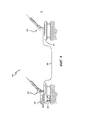
на фиг. 1 схематически показана диаграмма, иллюстрирующая раскрытую систему волоконной стабилизации разностей оптических длин пути в широком частотном диапазоне в течение длительных периодов времени в соответствии с по меньшей мере одним вариантом реализации настоящего изобретения.in FIG. 1 is a schematic diagram illustrating a disclosed system for fiber stabilization of differences in optical path lengths over a wide frequency range over long periods of time in accordance with at least one embodiment of the present invention.
На фиг. 2 схематически показана диаграмма, отражающая дополнительные подробности о раскрытой системе по фиг. 1 в соответствии по меньшей мере с одним вариантом реализации настоящего изобретения.In FIG. 2 is a schematic diagram showing additional details of the disclosed system of FIG. 1 in accordance with at least one embodiment of the present invention.
На фиг. 3 показана блок-схема, иллюстрирующая раскрытый способ волоконной стабилизации разностей оптических длин пути в широком частотном диапазоне в течение длительных периодов времени в соответствии с по меньшей мере одним вариантом реализации настоящего изобретения.In FIG. 3 is a flowchart illustrating the disclosed method for fiber stabilization of optical path length differences over a wide frequency range over long periods of time in accordance with at least one embodiment of the present invention.
На фиг. 4 схематически показана диаграмма, иллюстрирующая конфигурацию телескопа для раскрытой системы по фиг. 1 в соответствии по меньшей мере с одним вариантом реализации настоящего изобретения.In FIG. 4 is a schematic diagram illustrating a telescope configuration for the disclosed system of FIG. 1 in accordance with at least one embodiment of the present invention.
ОПИСАНИЕ ИЗОБРЕТЕНИЯDESCRIPTION OF THE INVENTION
Раскрытые в настоящей заявке способы и устройства предлагают работоспособную систему для волоконной стабилизации разностей оптических длин пути в широком частотном диапазоне в течение длительных периодов времени. Цель настоящего изобретения состоит в сборе света от двух телескопов через оптические волокна при минимальных разностях оптических длин пути и при минимальной оптической дисперсии, посредством использования эталонного лазера, соединенного с этими двумя оптическими волокнами. Пучок света от эталонного лазера излучается по направлению к каждому оптическому волокну и отражается в обратном направлении, а затем направляется в метрологический интерферометр. Происходят сбор выходного сигнала интерферометра и его обработка центральным процессором, где собранный сигнал об ошибке по фазе разделен на две отдельных полосы частот. Управляющая архитектура разделяет полосы частот, так что широкополосный (например, в диапазоне от частоты постоянного тока до частоты ≥5 килогерц) контур управления разностью оптических длин пути обеспечивает согласование длины путей оптического волокна на протяжении нескольких последовательных значений длин волны и синхронизацию по фазе с точностью не меньше 1/25 длины волны.The methods and devices disclosed in this application provide a workable system for fiber stabilization of differences in optical path lengths over a wide frequency range for long periods of time. An object of the present invention is to collect light from two telescopes through optical fibers with minimal differences in optical path lengths and with minimal optical dispersion, by using a reference laser coupled to these two optical fibers. A beam of light from a reference laser is emitted towards each optical fiber and is reflected in the opposite direction, and then sent to a metrological interferometer. The output signal of the interferometer is collected and processed by the central processor, where the collected error signal in phase is divided into two separate frequency bands. The control architecture separates the frequency bands, so that the broadband (for example, in the range from DC frequency to a frequency of ≥5 kilohertz) optical path difference path control ensures matching the path length of the optical fiber over several consecutive wavelengths and phase synchronization is not accurate less than 1/25 of the wavelength.
Для увеличения разрешающей способности изображения в астрономии были разработаны интерферометрические методики с использованием нескольких телескопов, отстоящих друг от друга на несколько метров. Для сбора излучения с минимальными разностями оптических длин пути используют набор подвижных зеркал, размещаемых в вакуумном туннеле (для устранения влияния турбулентности воздуха) для регулировки изменений разности оптических длин пути между двумя телескопами. Собранный свет посылают в интерферометр. Выходной сигнал интерферометра затем используют для регулировки изменений разности оптических длин пути посредством последовательности операций управления. Этот стандартный способ может быть довольно дорогим вследствие установки оборудования в вакуумных туннелях. Кроме того, использование вакуумных туннелей означает отсутствие мобильности или подвижности системы.To increase the resolution of the image in astronomy, interferometric techniques have been developed using several telescopes that are several meters apart. To collect radiation with minimal differences in optical path lengths, use a set of movable mirrors placed in a vacuum tunnel (to eliminate the effect of air turbulence) to adjust changes in the difference in optical path lengths between two telescopes. The collected light is sent to the interferometer. The output signal of the interferometer is then used to adjust changes in the difference in optical path lengths through a control flow. This standard method can be quite expensive due to the installation of equipment in vacuum tunnels. In addition, the use of vacuum tunnels means the lack of mobility or mobility of the system.
В настоящем изобретении применена известная основная технология, необходимая для пассивного синтетического/интерферометрического построения изображения. В качестве примера можно взять два телескопа с диаметром один метр, разнесенных на расстояние в 100 метров. Эти два телескопа способны обеспечить значение пространственного разрешения, в 100 раз превышающее разрешение одиночного телескопа с диаметром один метр. Следует отметить, что в других вариантах реализации диаметр телескопов может быть отличен от одного метра и расстояние между ними может быть отлично от 100 метров. Настоящее изобретение использует эту обычную технологию, но использует оптическое волокно для участков траектории (то есть для путей, по которым свет направляют от телескопа на детектор) вместо традиционного использования вакуумных туннелей для этих участков траектории. Использование оптического волокна для участков траектории обеспечивает возможность значительного уменьшения затрат на инфраструктуру и дает возможность перемещения телескопов или возможность создания мобильной системы построения изображения. Настоящее изобретение, при использовании оптического волокна для участков траектории, создает компактную систему построения изображения, которая может быть размещена на военных платформах (например, самолетах, спутниках, судах и на наземных транспортных средствах). Для использования выгод от использования участков траектории из оптического волокна для этой методики построения изображения необходим надежный устойчивый способ фазовой синхронизации разности оптических длин пути для двух волокон. К сожалению, использование оптических волокон для контроля разности оптических длин пути приводит к большему количеству затруднений и большей чувствительности к условиям окружающей среды по сравнению с традиционными вакуумными туннелями.The present invention employs the well-known core technology required for passive synthetic / interferometric imaging. As an example, you can take two telescopes with a diameter of one meter, spaced 100 meters apart. These two telescopes are capable of providing a
Настоящее изобретение описывает систему и способ для управления и фазовой синхронизации разности оптических длин пути на участках траектории из оптического волокна, обеспечивая тем самым существенную выгоду от использования оптических волокон. В частности, в настоящем изобретении использован эталонный лазер, связанный с этими двумя оптическими волокнами. Образованный лазером оптический пучок излучается по направлению к каждому оптическому волокну и отражается в обратном направлении, а затем направляется в метрологический интерферометр. Выполняется сбор выходного сигнала интерферометра и его обработка центральным процессором, где собранный сигнал об ошибке по фазе разделен на две отдельных полосы частот. Такое устройство управления использует отдельные полосы частот для управления разностью оптических длин пути. Одна полоса частот использована для управления низкочастотной компонентой (в диапазоне от частоты постоянного тока до частоты 1-5 Гц). Другая полоса частот использована для управления высокочастотной компонентой (от 1-5 Гц до 10 кГц). Разность оптических длин пути в оптических волокнах может быть очень чувствительна к внешним возмущениям. Определенные возмущения, подавляемые раскрытой конструкцией системы, представляют собой тепловые возмущения (в диапазоне от частоты постоянного тока до частоты 1-5 Гц), механические колебания (от 1-5 Гц до 1 кГц) и акустические колебания (от 2 Гц до 20 кГц). Посредством тщательного выбора типа используемого оптического волокна некоторые из этих возмущений могут быть минимизированы, но не полностью устранены. Настоящее изобретение предлагает схему, обеспечивающую возможность минимизации влияния этих возмущений посредством выполнения системы, устраняющей эти эффекты в указанных полосах частот. Это выполнено посредством тщательного управления приводами для разности оптических длин пути, которые предназначены для устранения эффектов, специфических для каждой полосы частот. При этом осуществляется независимое сервоуправление этими приводами посредством использования выходного сигнала интерферометра в качестве сигнала обратной связи. Индивидуальные контуры управления обеспечивают также возможность стабилизации изменений разности оптических длин пути до долей длины волны в течение очень долгих промежутков времени с минимальными дисперсионными эффектами.The present invention describes a system and method for controlling and phase locking the difference in optical path lengths on path sections of an optical fiber, thereby providing a substantial benefit from the use of optical fibers. In particular, the present invention uses a reference laser coupled to these two optical fibers. An optical beam formed by a laser is emitted towards each optical fiber and is reflected in the opposite direction, and then sent to a metrological interferometer. The interferometer output signal is collected and processed by the central processor, where the collected phase error signal is divided into two separate frequency bands. Such a control device uses separate frequency bands to control the difference in optical path lengths. One frequency band is used to control the low-frequency component (in the range from DC frequency to a frequency of 1-5 Hz). Another frequency band is used to control the high-frequency component (from 1-5 Hz to 10 kHz). The difference in optical path lengths in optical fibers can be very sensitive to external disturbances. Certain disturbances suppressed by the disclosed system design are thermal disturbances (in the range from direct current frequency to a frequency of 1-5 Hz), mechanical vibrations (from 1-5 Hz to 1 kHz) and acoustic vibrations (from 2 Hz to 20 kHz) . Through careful selection of the type of optical fiber used, some of these disturbances can be minimized, but not completely eliminated. The present invention provides a circuit to minimize the influence of these disturbances by implementing a system that eliminates these effects in the indicated frequency bands. This is done by carefully controlling the drives for the difference in optical path lengths, which are designed to eliminate effects specific to each frequency band. In this case, independent servo control of these drives is carried out by using the output signal of the interferometer as a feedback signal. Individual control loops also provide the ability to stabilize changes in the difference in optical path lengths to fractions of the wavelength for very long periods of time with minimal dispersion effects.
В настоящее время стабилизацию разности оптических длин пути в оптических волокнах традиционно осуществляют посредством введения пучка от метрологического лазера в волокно и отражения пучка от вибрирующего световозвращающего отражателя, вырабатывая, таким образом, модулированный по времени управляющий сигнал. Эта модуляция способна создавать дополнительный шум в волокне, однако она может быть ограничена посредством частотной модуляции. Кроме того, для управления разностью оптических длин пути обычно используют волоконные расширители (в диапазоне от частоты постоянного тока до частоты 5 кГц). Когда ширина волокна превышает 50 микрометров, дисперсионные эффекты начинают воздействовать на качество света, проходящего через волокно. Регулятор волоконного расширителя используют для компенсации влияния расширения волокна.Currently, the stabilization of the difference in optical path lengths in optical fibers is traditionally carried out by introducing a beam from a metrological laser into the fiber and reflecting the beam from a vibrating retroreflective reflector, thus generating a time-modulated control signal. This modulation is capable of creating additional noise in the fiber, however, it can be limited by frequency modulation. In addition, fiber expanders (in the range from DC to 5 kHz) are typically used to control the difference in optical path lengths. When the width of the fiber exceeds 50 micrometers, dispersion effects begin to affect the quality of the light passing through the fiber. A fiber expander regulator is used to compensate for the effects of fiber expansion.
Следует отметить, что настоящее изобретение избавляет от необходимости модуляции и демодуляции источника света или световозвращающего отражателя, не добавляя, таким образом, шума к существующему сигналу. Эта схема также минимизирует дисперсионные эффекты посредством ограничения расширения волокна менее чем одной длиной волны эталонного лазера. Управление долговременным дрейфом осуществляется посредством низкочастотного каскада.It should be noted that the present invention eliminates the need for modulation and demodulation of the light source or retroreflective reflector, without thereby adding noise to the existing signal. This design also minimizes dispersion effects by limiting fiber expansion to less than one wavelength of a reference laser. Long-term drift is controlled by a low-frequency stage.
В последующем описании сформулированы многочисленные подробности, предназначенные для более полного описания системы. Однако специалисту в данной области техники очевидно, что раскрытая система может быть осуществлена и без этих специфических подробностей. В других случаях известные особенности не были описаны подробно, чтобы не вносить в систему излишнюю неопределенность.In the following description, numerous details are set forth in order to more fully describe the system. However, it will be apparent to those skilled in the art that the disclosed system can be implemented without these specific details. In other cases, known features have not been described in detail so as not to introduce excessive uncertainty into the system.
На фиг. 1 схематически показана диаграмма, иллюстрирующая раскрытую систему 100 волоконной стабилизации разностей оптических длин пути в широком частотном диапазоне в течение длительных периодов времени в соответствии по меньшей мере с одним вариантом реализации настоящего изобретения. На этой фигуре лазер 105 излучает оптический пучок в первое оптическое волокно 110. Первое оптическое волокно 110 вместе со вторым оптическим волокном 115 соединены с расщепителем 120 пучка на 3 децибела. Расщепитель 120 пучка на 3 децибела расщепляет излученный оптический пучок пополам и выводит половину оптического пучка (называемую первым оптическим пучком) на первое оптическое волокно 110, а другую половину оптического пучка (называемую вторым оптическим пучком) на второе оптическое волокно 115.In FIG. 1 is a schematic diagram illustrating a disclosed
В качестве опции первый циркулятор 125 выполняет циркуляцию первого оптического пучка через связку 130 волокон (например, ххх метров волокна) и через волоконный расширитель 135 к трансляционному столику 140 регулируемого оптического телескопа 145. Первый оптический пучок отражен назад от первого зеркала 150 на трансляционном столике 140. Первый циркулятор 125 выполняет циркуляцию первого циркулирующего пучка, который содержит отраженный первый оптический пучок и пучок регулируемого оптического телескопа, к первому дихроичному расщепителю 155 пучка. Первый дихроичный расщепитель 155 пучка расщепляет первый циркулирующий пучок на первый оптический пучок и пучок регулируемого телескопа.Optionally, the
В качестве опции второй циркулятор 160 выполняет циркуляцию второго оптического пучка через связку волокон 165 (например, ххх метров волокна) и по выбору через волоконный расширитель 170 к эталонному оптическому телескопу 175. Второй оптический пучок отражается назад от второго зеркала 180 эталонного оптического телескопа 175. Второй циркулятор 160 выполняет циркуляцию второго циркулирующего пучка, который содержит отраженный второй оптический пучок и пучок эталонного оптического телескопа, ко второму дихроичному расщепителю 185 пучка. Второй дихроичный расщепитель 185 пучка разделяет второй циркулирующий пучок на второй оптический пучок и пучок эталонного телескопа.Optionally, the second circulator 160 circulates the second optical beam through a bundle of fibers 165 (for example, xxx meters of fiber) and optionally through a fiber expander 170 to the reference
Пучок регулируемого телескопа и пучок эталонного телескопа поступают в принимающий свет от телескопа интерферометр 190, используемый для формирования бинокулярного изображения. Первый оптический пучок отражается от зеркала 190 и вводится в оптическую скамью 195 интерферометра, определяющего разность оптических длин пути (например, интерферометра Майкельсона). В оптической скамье 195 интерферометра первый оптический пучок проходит через пластинку толщиной в половину длины волны (λ/2) с поляризацией в 22,5 градусов, в результате чего компоненты круговой поляризации (S1 и Р1) первого оптического пучка находятся в фазе друг с другом. Второй оптический пучок вводится в оптическую скамью 195 интерферометра. В оптической скамье 195 интерферометра второй оптический пучок проходит через пластинку толщиной в четверть длины волны (λ/4), в результате чего компоненты круговой поляризации (S2 и Р2) второго оптического пучка оказываются сдвинуты по фазе на 90 градусов друг от друга.The beam of the adjustable telescope and the beam of the reference telescope come into the receiving light from the
Первый оптический пучок и второй оптический пучок затем проходят через поляризационный расщепитель 107 пучка. Пучок с компонентами S1 и S2, где компоненты совпадают по фазе (то есть S1+S1=I (синфазный сигнал)), выводятся из оптической скамьи 195 интерферометра. Пучок с компонентами Р1 и Р2, где компоненты квадратурны (то есть Р1 (90 градусов)+Р2=Q (квадратурный сигнал)), выводится из оптической скамьи 195 интерферометра.The first optical beam and the second optical beam then pass through a
Широкополосный детектор 117 (в диапазоне от частоты постоянного тока до частоты 1,5 МГц) обнаруживает синфазный пучок (то есть пучок с компонентами S1 и S2) и вырабатывает усиленный синфазный сигнал. Другой широкополосный детектор 122 (в диапазоне от частоты постоянного тока до частоты 1,5 МГц) обнаруживает квадратурный пучок (то есть пучок с компонентами Р1 и Р2) и вырабатывает усиленный квадратурный сигнал. Следует отметить, что синфазный сигнал и квадратурный сигнал вместе образуют синусоидальный сигнал. Усиленный синфазный сигнал фильтруют фильтром 132 (с усилением, равным единице (G=1)) на карте 127 буфера фильтра, а усиленный квадратурный сигнал фильтруют фильтром 137 (с усилением, равным единице (G=1)) на карте 127 буфера фильтра. Отфильтрованный синфазный сигнал и отфильтрованный квадратурный сигнал поступают для обработки в программируемую пользователем вентильную матрицу (FPGA) на шасси 142 процессора для цифровой обработки сигналов.Broadband detector 117 (ranging from a DC frequency to a frequency of 1.5 MHz) detects an in-phase beam (i.e., a beam with components S1 and S2) and generates an amplified in-phase signal. Another broadband detector 122 (ranging from a DC frequency to a frequency of 1.5 MHz) detects a quadrature beam (i.e., a beam with components P1 and P2) and generates an amplified quadrature signal. It should be noted that the common-mode signal and the quadrature signal together form a sinusoidal signal. The amplified common-mode signal is filtered by filter 132 (with a gain equal to unity (G = 1)) on the
В программируемой пользователем вентильной матрице на шасси 142 процессора для цифровой обработки сигналов аналоговый отфильтрованный синфазный сигнал вводится в аналого-цифровой преобразователь 152 для формирования цифрового синфазного сигнала, а отфильтрованный аналоговый квадратурный сигнал вводят в аналого-цифровой преобразователь 147 для формирования цифрового квадратурного сигнала. Цифровой синфазный сигнал и цифровой квадратурный сигнал поступают для обработки в процессор 157 для цифровой обработки сигналов (или в качестве альтернативы в аналоговый контур управления с частотой больше 1,0 кГц с частотой выборки больше 20 кГц). После обработки процессор 157 для цифровой обработки сигналов подает на выход цифровой командный сигнал низкочастотного устройства и цифровой командный сигнал высокочастотного устройства. Цифровой командный сигнал низкочастотного устройства поступает в цифро-аналоговый преобразователь 162 для формирования аналогового командного сигнала низкочастотного устройства (в диапазоне от частоты постоянного тока до частоты 5 Гц), а командный сигнал высокочастотного устройства поступает в цифро-аналоговый преобразователь 167 для формирования аналогового командного сигнала высокочастотного устройства (в диапазоне частот от 5 Гц к 10 кГц).In a user-programmable gate array on the
Аналоговый командный сигнал низкочастотного устройства поступает в регулятор 172 столика. Регулятор 172 столика посылает сигнал (например, сигнал напряжения) для управления (то есть для выполнения скольжения назад и/или вперед) трансляционным столиком 140 согласно аналоговому сигналу низкочастотного устройства с целью введения поправки на разность оптических длин пути. Аналоговый сигнал высокочастотного устройства поступает в фильтр 182 (с усилением, равным единице (G=1)) на карте 192 буфера фильтра. Отфильтрованный аналоговый сигнал высокочастотного устройства поступает в устройство 197 электропитания волоконного расширителя. Устройство 197 электропитания волоконного расширителя посылает сигнал (например, сигнал напряжения) для управления волоконным расширителем 135 с целью введения поправки на разность оптических длин пути.The analog command signal of the low-frequency device enters the
На фиг. 2 схематически показана диаграмма 200, отражающая дополнительные подробности раскрытой системы 100 по фиг. 1 в соответствии по меньшей мере с одним вариантом реализации настоящего изобретения. Следует отметить, что для выполнения более упрощенного представления подробностей системы 100, эта фигура показывает только один из пучков/сигналов (то есть синфазный пучок/сигнал или квадратурный пучок/сигнал), проходящий через детектор 117, 122 и фильтр 137, 132. На этой фигуре пучок как таковой (то есть или синфазный пучок, или квадратурный пучок) поступает в детектор 117, 122. Детектор 117, 122 обнаруживает пучок и вырабатывает усиленный сигнал. Усиленный сигнал поступает в карту 127 буфера фильтра. Карта 127 буфера фильтра отфильтровывает усиленный сигнал с формированием отфильтрованного усиленного сигнала. Отфильтрованный аналоговый усиленный сигнал затем поступает в аналого-цифровой преобразователь 147, 152 для формирования цифрового сигнала.In FIG. 2 is a schematic diagram 200 illustrating additional details of the disclosed
Затем происходит масштабирование цифрового синусоидального сигнала устройством 205 масштабирования, путем сдвига на половину волну 210, и отсылка через узкополосный режекторный фильтр 215. В зависимости от положения нескольких переключателей 220 получаемый в результате сигнал посылают через низкочастотный канал или высокочастотный канал. Регулятор 225 низкочастотного устройства/высокочастотного устройства управляет положением переключателей 220. Следует отметить, что на фиг. 2 переключатели 220 изображены в положениях, приводящих к отсылке сигнала через низкочастотный канал. Для отсылки сигнала и по высокочастотному каналу, и по низкочастотному каналу переключатели 220 должны быть помещены в положения, противоположные тем, что показаны на фиг. 2. На выходе узкополосного режекторного фильтра 215 и на входе к переключателям 220 имеет место широкополосный сигнал ошибки, отсылаемый и в регулятор низкочастотного устройства и в регулятор высокочастотного устройства. Регулятор низкочастотного устройства сначала закрыт с обеспечением возможности успокоения, как в данный момент показано переключателями 220. Конструкция низкочастотного контура откликается на частоты в диапазоне от частоты постоянного тока до частоты 5 Гц. Как только ошибка низкочастотного устройства приблизительно равна нулю, происходит реверсирование переключателей таким образом, чтобы и низкочастотное устройство и высокочастотное устройство были заняты.Then, the digital sinusoidal signal is scaled by the
При прохождении сигнала через высокочастотный канал происходит интегрирование широкополосного сигнала ошибки устройством 225 интегрирования (wtbw/s, где wtbw=2*n*ftbw и ftbw=от 5 Гц до 20 кГц). Интегрированный сигнал затем подают через контур 230 управления. Контур 230 управления вырабатывает цифровой командный сигнал высокочастотного устройства. Цифровой командный сигнал высокочастотного устройства поступает в цифро-аналоговый преобразователь 167 для формирования аналогового командного сигнала высокочастотного устройства. Аналоговый командный сигнал высокочастотного устройства поступает в пьезоусилитель для усиления и фильтрования. Усиленный аналоговый командный сигнал высокочастотного устройства затем поступает в устройство 197 электропитания волоконного расширителя, содержащее управляющий контур обратной связи. Устройство 197 электропитания волоконного расширителя посылает сигнал (например, сигнал напряжения), предназначенный для управления волоконным расширителем 135 для внесения поправки на разность оптических длин пути.When the signal passes through the high-frequency channel, the broadband error signal is integrated by the integration device 225 (wtbw / s, where wtbw = 2 * n * ftbw and ftbw = from 5 Hz to 20 kHz). The integrated signal is then supplied through a
При прохождении сигнала через низкочастотный канал цифровой сигнал поступает в цифро-аналоговый преобразователь 162 для формирования аналогового сигнала. Аналоговый сигнал затем поступает в регулятор 172 столика. Внутри регулятора 172 столика аналоговый сигнал поступает в аналого-цифровой преобразователь 240 для формирования цифрового сигнала. Затем происходит интегрирование этого цифрового сигнала устройством интегрирования 245 (wo/s, где wo=2*n*fo и fo~1-5 Гц). Получившийся в результате сигнал посылают через контур управления 250 обратной связью для формирования управляющего сигнала. Регулятор 172 столика посылает управляющий сигнал (например, сигнал напряжения) для управления (то есть для выполнения скольжения назад и/или вперед) трансляционным столиком 140 согласно аналоговому сигналу низкочастотного устройства с целью введения поправки на разность оптических длин пути.When the signal passes through the low-frequency channel, the digital signal enters the digital-to-
На фиг. 3 показана блок-схема 300, иллюстрирующая раскрытый способ волоконной стабилизации разности оптических длин пути в широком частотном диапазоне в течение длительных периодов времени в соответствии по меньшей мере с одним вариантом реализации настоящего изобретения. После начала (операция 305) последовательности операций способа 100 лазер излучает оптический пучок (операция 310). Затем расщепитель пучка разделяет оптический пучок на первый оптический пучок и второй оптический пучок (операция 315).In FIG. 3 is a
Первый циркулятор выполняет циркуляцию первого оптического пучка через волоконный расширитель к трансляционному столику регулируемого оптического телескопа (операция 320). Затем первое зеркало на трансляционном столике отражает первый оптический пучок (операция 325). Первый циркулятор затем выполняет циркуляцию первого циркулирующего пучка, который содержит первый оптический пучок и пучок регулируемого оптического телескопа, к первому дихроичному расщепителю пучка (операция 330). Первый дихроичный расщепитель пучка расщепляет первый циркулирующий пучок на первый оптический пучок и пучок регулируемого оптического телескопа (операция 335).The first circulator circulates the first optical beam through a fiber expander to the translation table of an adjustable optical telescope (operation 320). Then, the first mirror on the translation table reflects the first optical beam (operation 325). The first circulator then circulates the first circulating beam, which contains the first optical beam and the beam of the adjustable optical telescope, to the first dichroic beam splitter (operation 330). The first dichroic beam splitter splits the first circulating beam into a first optical beam and a beam from an adjustable optical telescope (operation 335).
Второй циркулятор выполняет циркуляцию второго оптического пучка к эталонному оптическому телескопу (операция 340). Затем второе зеркало отражает второй оптический пучок (операция 345). Второй циркулятор затем выполняет циркуляцию второго циркулирующего пучка, который содержит второй оптический пучок и пучок эталонного оптического телескопа, ко второму дихроичному расщепителю пучка (операция 350). Второй дихроичный расщепитель пучка расщепляет второй циркулирующий пучок на второй оптический пучок и пучок эталонного оптического телескопа (операция 355).The second circulator circulates the second optical beam to the reference optical telescope (operation 340). Then, the second mirror reflects the second optical beam (operation 345). The second circulator then circulates the second circulating beam, which contains the second optical beam and the beam of the reference optical telescope, to the second dichroic beam splitter (operation 350). A second dichroic beam splitter splits the second circulating beam into a second optical beam and a reference optical telescope beam (operation 355).
Первый оптический пучок и второй оптический пучок поступают в интерферометр (операция 360). Интерферометр подает на выход синфазный сигнал и квадратурный сигнал, которые вместе образуют синусоидальный сигнал (операция 365). Затем по меньшей мере один процессор фильтрует синусоидальный сигнал с формированием высокочастотного сигнала и низкочастотного сигнала (операция 370). Регулятор столика управляет трансляционным столиком посредством использовании низкочастотного сигнала (операция 375). Регулятор волоконного расширителя управляет волоконным расширителем посредством использования высокочастотного сигнала (операция 380). Способ 300 оканчивается операцией 385.The first optical beam and the second optical beam enter the interferometer (operation 360). The interferometer outputs an in-phase signal and a quadrature signal, which together form a sinusoidal signal (operation 365). Then, at least one processor filters a sinusoidal signal to produce a high-frequency signal and a low-frequency signal (operation 370). The table controller controls the broadcast table by using a low-frequency signal (operation 375). The fiber expander controller controls the fiber expander by using a high frequency signal (operation 380).
На фиг. 4 схематически показана диаграмма, иллюстрирующая конфигурацию телескопа 400 для раскрытой системы 100 по фиг. 1 в соответствии по меньшей мере с одним вариантом реализации настоящего изобретения. В частности, эти данные показывают основную геометрию телескопа, где управляют разностью оптических длин пути между отдельными телескопами 410, 420 для поддержания оптической фазовой когерентности между двумя телескопами 410, 420. Телескоп 410 представляет собой эталонный оптический телескоп, а телескоп 420 представляет собой регулируемый оптический телескоп. Во время работы разность оптических длин пути определяют посредством интерферометра на скамье 430 для определения разности оптических длин пути, и регулятор определяет, что необходимы коррекции. Подвижная оптическая скамья 440 выполняет коррекцию низкочастотной разности оптических длин пути. Коррекция высокочастотной разности оптических длин пути выполнена посредством волоконного расширителя 450, расширяющего оптико-волоконный кабель 460.In FIG. 4 is a schematic diagram illustrating a configuration of a
Хотя здесь были раскрыты определенные иллюстративные варианты реализации и способы, для специалистов в данной области техники может быть очевидно из предшествующего раскрытия, что вариации и модификации таких воплощений и способов могут быть выполнены без отступления от истинной сути и объема настоящего раскрытого изобретения. Существует много других примеров реализации раскрытого изобретения, каждый из которых отличен от других лишь незначительными подробностями. В соответствии с этим мы заявляем, что раскрытое изобретение должно быть ограничено только до степени, требуемой приложенными пунктами формулы изобретения и правилами и принципами применяемого законодательства.Although certain illustrative embodiments and methods have been disclosed herein, it will be apparent to those skilled in the art from the foregoing disclosure that variations and modifications of such embodiments and methods can be made without departing from the true spirit and scope of the present disclosed invention. There are many other examples of implementation of the disclosed invention, each of which is distinguished from the others by only minor details. Accordingly, we declare that the disclosed invention should be limited only to the extent required by the attached claims and the rules and principles of applicable law.
Claims (50)
Applications Claiming Priority (2)
| Application Number | Priority Date | Filing Date | Title |
|---|---|---|---|
| US13/745,608 US9041992B2 (en) | 2013-01-18 | 2013-01-18 | Fiber stabilization of optical path differences (OPD) over a wide bandwidth frequency range for extended periods of time |
| US13/745,608 | 2013-01-18 |
Publications (2)
| Publication Number | Publication Date |
|---|---|
| RU2014100684A RU2014100684A (en) | 2015-07-20 |
| RU2642124C2 true RU2642124C2 (en) | 2018-01-24 |
Family
ID=49955194
Family Applications (1)
| Application Number | Title | Priority Date | Filing Date |
|---|---|---|---|
| RU2014100684A RU2642124C2 (en) | 2013-01-18 | 2014-01-13 | Fibre stabilization of optical path length difference in wide frequency range for long period of time |
Country Status (5)
| Country | Link |
|---|---|
| US (1) | US9041992B2 (en) |
| EP (1) | EP2757396B1 (en) |
| JP (1) | JP6272042B2 (en) |
| CN (1) | CN103944055B (en) |
| RU (1) | RU2642124C2 (en) |
Families Citing this family (3)
| Publication number | Priority date | Publication date | Assignee | Title |
|---|---|---|---|---|
| CN105446120A (en) * | 2015-11-25 | 2016-03-30 | 天津大学 | Optical fiber link time-frequency distribution device based on femtosecond laser and stabilizing method thereof |
| CN107947859A (en) * | 2017-12-12 | 2018-04-20 | 北京无线电计量测试研究所 | A kind of optical fiber transmission delay compensation device and system |
| CN108828764A (en) * | 2018-03-30 | 2018-11-16 | 深圳市华讯方舟太赫兹科技有限公司 | A kind of optical-fiber drawing device and optical fiber delay scanning system |
Citations (3)
| Publication number | Priority date | Publication date | Assignee | Title |
|---|---|---|---|---|
| JPH06201320A (en) * | 1992-10-06 | 1994-07-19 | Csem Centre Suisse Electron & De Microtech Sa Rech & Dev | Interferometer having built-in unit and reflection unit which are mutually separated with measuring part |
| US20040052459A1 (en) * | 2000-06-14 | 2004-03-18 | Battiato James M. | Method to stabilize and adjust the optical path length of waveguide devices |
| US6738408B2 (en) * | 2000-09-11 | 2004-05-18 | Communications Research Laboratory, Independent Administrative Institution | Mode-locked laser apparatus |
Family Cites Families (10)
| Publication number | Priority date | Publication date | Assignee | Title |
|---|---|---|---|---|
| US4505588A (en) * | 1983-02-09 | 1985-03-19 | Ludman Jacques E | Fiber stellar interferometer |
| FR2671868B1 (en) * | 1991-01-22 | 1993-04-30 | Aerospatiale | INTERFEROMETRIC DEVICE, ESPECIALLY STELLAR, WITH A DELAYED LINE. |
| JPH0560781A (en) * | 1991-09-05 | 1993-03-12 | Matsushita Electric Ind Co Ltd | Acceleration measuring apparatus |
| JP2657018B2 (en) * | 1991-12-24 | 1997-09-24 | 日本電信電話株式会社 | Optical Connector Return Loss Measurement System |
| US5515199A (en) * | 1995-01-31 | 1996-05-07 | Photonic Applications, Inc. | Optical system employing near-incoherent processing for distortion correction |
| US6141099A (en) * | 1998-11-17 | 2000-10-31 | Trw Inc. | Compact, variable length interferometer delay stage |
| US7154608B1 (en) * | 2003-10-29 | 2006-12-26 | The Board Of Trustees Of Southern Illnois University | Phase-preserving amplifier for a stellar interferometer |
| GB2411066B (en) * | 2004-02-14 | 2009-04-29 | Oti Ophthalmic Technologies | Compact high resolution imaging apparatus |
| US7576868B2 (en) * | 2007-06-08 | 2009-08-18 | Zygo Corporation | Cyclic error compensation in interferometry systems |
| JP5509001B2 (en) * | 2010-09-08 | 2014-06-04 | 日本電信電話株式会社 | Optical path length difference detection and adjustment device for duplex optical line |
-
2013
- 2013-01-18 US US13/745,608 patent/US9041992B2/en active Active
-
2014
- 2014-01-09 EP EP14150572.7A patent/EP2757396B1/en active Active
- 2014-01-13 RU RU2014100684A patent/RU2642124C2/en active
- 2014-01-15 JP JP2014005234A patent/JP6272042B2/en active Active
- 2014-01-20 CN CN201410024202.XA patent/CN103944055B/en active Active
Patent Citations (3)
| Publication number | Priority date | Publication date | Assignee | Title |
|---|---|---|---|---|
| JPH06201320A (en) * | 1992-10-06 | 1994-07-19 | Csem Centre Suisse Electron & De Microtech Sa Rech & Dev | Interferometer having built-in unit and reflection unit which are mutually separated with measuring part |
| US20040052459A1 (en) * | 2000-06-14 | 2004-03-18 | Battiato James M. | Method to stabilize and adjust the optical path length of waveguide devices |
| US6738408B2 (en) * | 2000-09-11 | 2004-05-18 | Communications Research Laboratory, Independent Administrative Institution | Mode-locked laser apparatus |
Non-Patent Citations (1)
| Title |
|---|
| Serge Olivier и др. MAFL experiment: development of photonic devices for a space-based multiaperture fiber-linked interferometer, PPLIED OPTICS, Vol. 46, No. 6, 20 February 2007. * |
Also Published As
| Publication number | Publication date |
|---|---|
| US20140204439A1 (en) | 2014-07-24 |
| US9041992B2 (en) | 2015-05-26 |
| EP2757396B1 (en) | 2017-03-22 |
| CN103944055B (en) | 2018-11-13 |
| JP6272042B2 (en) | 2018-01-31 |
| EP2757396A1 (en) | 2014-07-23 |
| CN103944055A (en) | 2014-07-23 |
| JP2014194526A (en) | 2014-10-09 |
| RU2014100684A (en) | 2015-07-20 |
Similar Documents
| Publication | Publication Date | Title |
|---|---|---|
| JP6300381B2 (en) | Magnetic field measuring device | |
| JP6314202B2 (en) | Coherent laser array control system and method | |
| RU2642124C2 (en) | Fibre stabilization of optical path length difference in wide frequency range for long period of time | |
| CN101430190B (en) | Interferometer | |
| WO2014203654A1 (en) | Distance measurement device, shape measurement device, processing system, distance measurement method, shape measurement method, and processing method | |
| JP2004088120A (en) | Method for stably controlling short pulse laser | |
| JP6727693B2 (en) | Optical scanning | |
| JP2015521386A5 (en) | ||
| US7957435B2 (en) | Electronically controlled optical scanning | |
| US20060088074A1 (en) | Amplified beam source | |
| US20150138563A1 (en) | Polarization sensitive optical coherence tomography | |
| US9702685B2 (en) | Broadband wavelength-swept light source system and apparatus employing the same | |
| JP2009276389A (en) | Terahertz wave-generating device and terahertz wave-generating method | |
| JPH01276786A (en) | Method and apparatus for automatic frequency control of semiconductor laser | |
| Bauer-Marschallinger et al. | Low-cost parallelization of optical fiber based detectors for photoacoustic imaging | |
| US8134715B2 (en) | Adjustable interferometer for laser ultrasonic measurement | |
| US7768699B2 (en) | Laser phase difference detecting device and laser phase control device | |
| WO2015046070A1 (en) | Optical measuring apparatus and optical measuring method | |
| JP2017108017A (en) | Laser device and measuring apparatus using the same | |
| KR20130023187A (en) | Optical coherence tomography using active mode-locking fiber laser | |
| JP2014194526A5 (en) | ||
| JPH0634446A (en) | Polarization dispersion measurement method and device using fixed analyzer | |
| KR101832553B1 (en) | Method and apparatus for characterizing timing jitter of femtosecond laser with dynamic range over several hundred decibels | |
| JP5404434B2 (en) | Phase control device | |
| JP5231554B2 (en) | Frequency stabilized laser device and laser frequency stabilizing method |