RU2637496C2 - System for providing vehicle with energy containing magnetizable material - Google Patents
System for providing vehicle with energy containing magnetizable material Download PDFInfo
- Publication number
- RU2637496C2 RU2637496C2 RU2014150421A RU2014150421A RU2637496C2 RU 2637496 C2 RU2637496 C2 RU 2637496C2 RU 2014150421 A RU2014150421 A RU 2014150421A RU 2014150421 A RU2014150421 A RU 2014150421A RU 2637496 C2 RU2637496 C2 RU 2637496C2
- Authority
- RU
- Russia
- Prior art keywords
- elements
- magnetizable material
- field
- layer
- forming layer
- Prior art date
Links
Images
Classifications
-
- H—ELECTRICITY
- H01—ELECTRIC ELEMENTS
- H01F—MAGNETS; INDUCTANCES; TRANSFORMERS; SELECTION OF MATERIALS FOR THEIR MAGNETIC PROPERTIES
- H01F27/00—Details of transformers or inductances, in general
- H01F27/24—Magnetic cores
-
- B—PERFORMING OPERATIONS; TRANSPORTING
- B60—VEHICLES IN GENERAL
- B60L—PROPULSION OF ELECTRICALLY-PROPELLED VEHICLES; SUPPLYING ELECTRIC POWER FOR AUXILIARY EQUIPMENT OF ELECTRICALLY-PROPELLED VEHICLES; ELECTRODYNAMIC BRAKE SYSTEMS FOR VEHICLES IN GENERAL; MAGNETIC SUSPENSION OR LEVITATION FOR VEHICLES; MONITORING OPERATING VARIABLES OF ELECTRICALLY-PROPELLED VEHICLES; ELECTRIC SAFETY DEVICES FOR ELECTRICALLY-PROPELLED VEHICLES
- B60L5/00—Current collectors for power supply lines of electrically-propelled vehicles
- B60L5/005—Current collectors for power supply lines of electrically-propelled vehicles without mechanical contact between the collector and the power supply line
-
- B—PERFORMING OPERATIONS; TRANSPORTING
- B60—VEHICLES IN GENERAL
- B60L—PROPULSION OF ELECTRICALLY-PROPELLED VEHICLES; SUPPLYING ELECTRIC POWER FOR AUXILIARY EQUIPMENT OF ELECTRICALLY-PROPELLED VEHICLES; ELECTRODYNAMIC BRAKE SYSTEMS FOR VEHICLES IN GENERAL; MAGNETIC SUSPENSION OR LEVITATION FOR VEHICLES; MONITORING OPERATING VARIABLES OF ELECTRICALLY-PROPELLED VEHICLES; ELECTRIC SAFETY DEVICES FOR ELECTRICALLY-PROPELLED VEHICLES
- B60L53/00—Methods of charging batteries, specially adapted for electric vehicles; Charging stations or on-board charging equipment therefor; Exchange of energy storage elements in electric vehicles
- B60L53/30—Constructional details of charging stations
- B60L53/35—Means for automatic or assisted adjustment of the relative position of charging devices and vehicles
- B60L53/38—Means for automatic or assisted adjustment of the relative position of charging devices and vehicles specially adapted for charging by inductive energy transfer
- B60L53/39—Means for automatic or assisted adjustment of the relative position of charging devices and vehicles specially adapted for charging by inductive energy transfer with position-responsive activation of primary coils
-
- B—PERFORMING OPERATIONS; TRANSPORTING
- B60—VEHICLES IN GENERAL
- B60L—PROPULSION OF ELECTRICALLY-PROPELLED VEHICLES; SUPPLYING ELECTRIC POWER FOR AUXILIARY EQUIPMENT OF ELECTRICALLY-PROPELLED VEHICLES; ELECTRODYNAMIC BRAKE SYSTEMS FOR VEHICLES IN GENERAL; MAGNETIC SUSPENSION OR LEVITATION FOR VEHICLES; MONITORING OPERATING VARIABLES OF ELECTRICALLY-PROPELLED VEHICLES; ELECTRIC SAFETY DEVICES FOR ELECTRICALLY-PROPELLED VEHICLES
- B60L9/00—Electric propulsion with power supply external to the vehicle
-
- B—PERFORMING OPERATIONS; TRANSPORTING
- B60—VEHICLES IN GENERAL
- B60M—POWER SUPPLY LINES, AND DEVICES ALONG RAILS, FOR ELECTRICALLY- PROPELLED VEHICLES
- B60M1/00—Power supply lines for contact with collector on vehicle
- B60M1/02—Details
- B60M1/06—Arrangements along the power lines for reducing interference in nearby communication lines
-
- H—ELECTRICITY
- H01—ELECTRIC ELEMENTS
- H01F—MAGNETS; INDUCTANCES; TRANSFORMERS; SELECTION OF MATERIALS FOR THEIR MAGNETIC PROPERTIES
- H01F27/00—Details of transformers or inductances, in general
- H01F27/28—Coils; Windings; Conductive connections
-
- H—ELECTRICITY
- H01—ELECTRIC ELEMENTS
- H01F—MAGNETS; INDUCTANCES; TRANSFORMERS; SELECTION OF MATERIALS FOR THEIR MAGNETIC PROPERTIES
- H01F27/00—Details of transformers or inductances, in general
- H01F27/34—Special means for preventing or reducing unwanted electric or magnetic effects, e.g. no-load losses, reactive currents, harmonics, oscillations, leakage fields
- H01F27/36—Electric or magnetic shields or screens
- H01F27/361—Electric or magnetic shields or screens made of combinations of electrically conductive material and ferromagnetic material
-
- H—ELECTRICITY
- H01—ELECTRIC ELEMENTS
- H01F—MAGNETS; INDUCTANCES; TRANSFORMERS; SELECTION OF MATERIALS FOR THEIR MAGNETIC PROPERTIES
- H01F38/00—Adaptations of transformers or inductances for specific applications or functions
- H01F38/14—Inductive couplings
-
- H—ELECTRICITY
- H01—ELECTRIC ELEMENTS
- H01F—MAGNETS; INDUCTANCES; TRANSFORMERS; SELECTION OF MATERIALS FOR THEIR MAGNETIC PROPERTIES
- H01F41/00—Apparatus or processes specially adapted for manufacturing or assembling magnets, inductances or transformers; Apparatus or processes specially adapted for manufacturing materials characterised by their magnetic properties
- H01F41/02—Apparatus or processes specially adapted for manufacturing or assembling magnets, inductances or transformers; Apparatus or processes specially adapted for manufacturing materials characterised by their magnetic properties for manufacturing cores, coils, or magnets
- H01F41/04—Apparatus or processes specially adapted for manufacturing or assembling magnets, inductances or transformers; Apparatus or processes specially adapted for manufacturing materials characterised by their magnetic properties for manufacturing cores, coils, or magnets for manufacturing coils
- H01F41/06—Coil winding
-
- B—PERFORMING OPERATIONS; TRANSPORTING
- B60—VEHICLES IN GENERAL
- B60L—PROPULSION OF ELECTRICALLY-PROPELLED VEHICLES; SUPPLYING ELECTRIC POWER FOR AUXILIARY EQUIPMENT OF ELECTRICALLY-PROPELLED VEHICLES; ELECTRODYNAMIC BRAKE SYSTEMS FOR VEHICLES IN GENERAL; MAGNETIC SUSPENSION OR LEVITATION FOR VEHICLES; MONITORING OPERATING VARIABLES OF ELECTRICALLY-PROPELLED VEHICLES; ELECTRIC SAFETY DEVICES FOR ELECTRICALLY-PROPELLED VEHICLES
- B60L2200/00—Type of vehicles
- B60L2200/18—Buses
-
- B—PERFORMING OPERATIONS; TRANSPORTING
- B60—VEHICLES IN GENERAL
- B60L—PROPULSION OF ELECTRICALLY-PROPELLED VEHICLES; SUPPLYING ELECTRIC POWER FOR AUXILIARY EQUIPMENT OF ELECTRICALLY-PROPELLED VEHICLES; ELECTRODYNAMIC BRAKE SYSTEMS FOR VEHICLES IN GENERAL; MAGNETIC SUSPENSION OR LEVITATION FOR VEHICLES; MONITORING OPERATING VARIABLES OF ELECTRICALLY-PROPELLED VEHICLES; ELECTRIC SAFETY DEVICES FOR ELECTRICALLY-PROPELLED VEHICLES
- B60L2200/00—Type of vehicles
- B60L2200/26—Rail vehicles
-
- H—ELECTRICITY
- H01—ELECTRIC ELEMENTS
- H01Q—ANTENNAS, i.e. RADIO AERIALS
- H01Q17/00—Devices for absorbing waves radiated from an antenna; Combinations of such devices with active antenna elements or systems
-
- Y—GENERAL TAGGING OF NEW TECHNOLOGICAL DEVELOPMENTS; GENERAL TAGGING OF CROSS-SECTIONAL TECHNOLOGIES SPANNING OVER SEVERAL SECTIONS OF THE IPC; TECHNICAL SUBJECTS COVERED BY FORMER USPC CROSS-REFERENCE ART COLLECTIONS [XRACs] AND DIGESTS
- Y02—TECHNOLOGIES OR APPLICATIONS FOR MITIGATION OR ADAPTATION AGAINST CLIMATE CHANGE
- Y02T—CLIMATE CHANGE MITIGATION TECHNOLOGIES RELATED TO TRANSPORTATION
- Y02T10/00—Road transport of goods or passengers
- Y02T10/60—Other road transportation technologies with climate change mitigation effect
- Y02T10/70—Energy storage systems for electromobility, e.g. batteries
-
- Y—GENERAL TAGGING OF NEW TECHNOLOGICAL DEVELOPMENTS; GENERAL TAGGING OF CROSS-SECTIONAL TECHNOLOGIES SPANNING OVER SEVERAL SECTIONS OF THE IPC; TECHNICAL SUBJECTS COVERED BY FORMER USPC CROSS-REFERENCE ART COLLECTIONS [XRACs] AND DIGESTS
- Y02—TECHNOLOGIES OR APPLICATIONS FOR MITIGATION OR ADAPTATION AGAINST CLIMATE CHANGE
- Y02T—CLIMATE CHANGE MITIGATION TECHNOLOGIES RELATED TO TRANSPORTATION
- Y02T10/00—Road transport of goods or passengers
- Y02T10/60—Other road transportation technologies with climate change mitigation effect
- Y02T10/7072—Electromobility specific charging systems or methods for batteries, ultracapacitors, supercapacitors or double-layer capacitors
-
- Y—GENERAL TAGGING OF NEW TECHNOLOGICAL DEVELOPMENTS; GENERAL TAGGING OF CROSS-SECTIONAL TECHNOLOGIES SPANNING OVER SEVERAL SECTIONS OF THE IPC; TECHNICAL SUBJECTS COVERED BY FORMER USPC CROSS-REFERENCE ART COLLECTIONS [XRACs] AND DIGESTS
- Y02—TECHNOLOGIES OR APPLICATIONS FOR MITIGATION OR ADAPTATION AGAINST CLIMATE CHANGE
- Y02T—CLIMATE CHANGE MITIGATION TECHNOLOGIES RELATED TO TRANSPORTATION
- Y02T90/00—Enabling technologies or technologies with a potential or indirect contribution to GHG emissions mitigation
- Y02T90/10—Technologies relating to charging of electric vehicles
- Y02T90/12—Electric charging stations
-
- Y—GENERAL TAGGING OF NEW TECHNOLOGICAL DEVELOPMENTS; GENERAL TAGGING OF CROSS-SECTIONAL TECHNOLOGIES SPANNING OVER SEVERAL SECTIONS OF THE IPC; TECHNICAL SUBJECTS COVERED BY FORMER USPC CROSS-REFERENCE ART COLLECTIONS [XRACs] AND DIGESTS
- Y02—TECHNOLOGIES OR APPLICATIONS FOR MITIGATION OR ADAPTATION AGAINST CLIMATE CHANGE
- Y02T—CLIMATE CHANGE MITIGATION TECHNOLOGIES RELATED TO TRANSPORTATION
- Y02T90/00—Enabling technologies or technologies with a potential or indirect contribution to GHG emissions mitigation
- Y02T90/10—Technologies relating to charging of electric vehicles
- Y02T90/14—Plug-in electric vehicles
-
- Y—GENERAL TAGGING OF NEW TECHNOLOGICAL DEVELOPMENTS; GENERAL TAGGING OF CROSS-SECTIONAL TECHNOLOGIES SPANNING OVER SEVERAL SECTIONS OF THE IPC; TECHNICAL SUBJECTS COVERED BY FORMER USPC CROSS-REFERENCE ART COLLECTIONS [XRACs] AND DIGESTS
- Y10—TECHNICAL SUBJECTS COVERED BY FORMER USPC
- Y10T—TECHNICAL SUBJECTS COVERED BY FORMER US CLASSIFICATION
- Y10T29/00—Metal working
- Y10T29/49—Method of mechanical manufacture
- Y10T29/49002—Electrical device making
- Y10T29/4902—Electromagnet, transformer or inductor
- Y10T29/49071—Electromagnet, transformer or inductor by winding or coiling
Landscapes
- Engineering & Computer Science (AREA)
- Power Engineering (AREA)
- Mechanical Engineering (AREA)
- Transportation (AREA)
- Life Sciences & Earth Sciences (AREA)
- Sustainable Development (AREA)
- Sustainable Energy (AREA)
- Manufacturing & Machinery (AREA)
- Electric Propulsion And Braking For Vehicles (AREA)
- Shielding Devices Or Components To Electric Or Magnetic Fields (AREA)
- Regulation Of General Use Transformers (AREA)
- Vehicle Interior And Exterior Ornaments, Soundproofing, And Insulation (AREA)
Abstract
Description
Изобретение относится к системе обеспечения транспортного средства энергией посредством магнитной индукции. Система содержит проводниковую структуру или конструкцию первичной стороны, адаптированную для создания электромагнитного поля, при прохождении переменного электрического тока течет через проводниковую структуру, и формирующий поле слой, содержащий намагничиваемый материал, адаптированный для формирования магнитных силовых линий электромагнитного поля.The invention relates to a system for providing a vehicle with energy by magnetic induction. The system comprises a conductor structure or primary side structure adapted to create an electromagnetic field, when an alternating electric current passes through the conductor structure, and a field-forming layer containing magnetizable material adapted to form magnetic field lines of the electromagnetic field.
Кроме того, изобретение относится к соответствующему способу формирования системы и средствам, адаптированным для формирования магнитных силовых линий электромагнитного поля, которое создается электрической проводниковой структурой.In addition, the invention relates to a corresponding method of forming a system and means adapted for forming magnetic field lines of an electromagnetic field that is created by an electrical conductor structure.
Во время работы системы обеспечения транспортных средств энергией посредством магнитной индукции, электромагнитное поле, которое создается проводниковой структурой первичной стороны, принимается приемным устройством на вторичной стороне (стороне транспортного средства), и энергия электромагнитного поля преобразуется назад в электрическую энергию посредством магнитной индукции. Изобретение относится в особенности к первичной стороне такой системы. Приемное устройство может быть названо "приемником" (pick-up) и является частью транспортного средства, в то время как электрическая проводниковая структура первичной стороны типично утоплена в земле или иным способом механически соединена с полосой движения транспортного средства или с местом, причем транспортное средством может останавливаться или парковаться.During operation of the system for providing vehicles with energy by magnetic induction, the electromagnetic field that is generated by the conductor structure of the primary side is received by the receiver on the secondary side (vehicle side), and the energy of the electromagnetic field is converted back into electrical energy by magnetic induction. The invention relates in particular to the primary side of such a system. The receiving device may be called a “pick-up” and is part of the vehicle, while the electrical conductor structure of the primary side is typically recessed in the ground or otherwise mechanically connected to the vehicle’s lane or place, and the vehicle may stop or park.
Термины "первичная сторона" и "вторичная сторона" используются соответственно терминологии, которая используется для трансформаторов. Фактически электрические части системы для передачи энергии от полосы движения транспортного средства или остановки транспортного средства к транспортному средству посредством индукции образуют разновидность трансформатора. Единственным отличием по сравнению с обычным трансформатором является факт, что транспортное средство, и таким образом вторичная сторона, может двигаться.The terms "primary side" and "secondary side" are used respectively in the terminology that is used for transformers. In fact, the electrical parts of the system for transmitting energy from a vehicle lane or stopping a vehicle to a vehicle by induction form a kind of transformer. The only difference compared to a conventional transformer is the fact that the vehicle, and thus the secondary side, can move.
WO 2010/000495 А1 описывает систему и способ для передачи электрической энергии к транспортному средству. Энергия может быть передана транспортному средству, в то время как транспортное средство движется. В то время как настоящее изобретение может относиться к подобной системе, оно не ограничено передачей энергии к движущемуся транспортному средству. Скорее энергия может передаваться, в то время как транспортное средство временно останавливается (как, например, автобус на автобусной остановке) или в то время как транспортное средство запарковано.WO 2010/000495 A1 describes a system and method for transmitting electrical energy to a vehicle. Energy can be transferred to the vehicle while the vehicle is moving. While the present invention may relate to such a system, it is not limited to transferring energy to a moving vehicle. Rather, energy can be transmitted while the vehicle is temporarily stopped (such as a bus at a bus stop) or while the vehicle is parked.
Транспортное средство может быть любым сухопутным транспортным средством, включая колейные, т.е. привязанные к полосе движения транспортные средства, такие как обычное рельсовое транспортное средство, монорельсовое транспортное средство, троллейбусы и транспортные средства, которые ведутся по полосе движения другими средствами. Другими примерами сухопутных транспортных средств являются дорожные автомобили, включая автобусы, которые не привязаны к полосе движения. Например, транспортным средством может быть транспортное средство, имеющее электрический ходовой двигатель. Транспортное средство может также быть транспортным средством, имеющим гибридную двигательную систему, например систему, которая может приводиться в действие электрической энергией или другой энергией, такой как электрохимически запасенная энергия или топливо (например, природный газ или бензин).The vehicle may be any land vehicle, including gauge vehicles, i.e. lane-bound vehicles, such as a conventional rail vehicle, a monorail vehicle, trolley buses and vehicles that are driven in a lane by other means. Other examples of land vehicles are road vehicles, including buses that are not tied to a lane. For example, the vehicle may be a vehicle having an electric propulsion engine. The vehicle may also be a vehicle having a hybrid propulsion system, for example a system that can be driven by electric energy or other energy, such as electrochemically stored energy or fuel (e.g., natural gas or gasoline).
WO 2010/000495 А1 описывает пример извивающихся обмоток на первичной стороне для создания электромагнитного поля. Проводниковая конструкция первичной стороны настоящего изобретения, которая изготовлена из электропроводящего материала, который во время работы создает электромагнитное поле, в то время как по электропроводящему материалу течет переменный электрический ток, может иметь одну и ту же или разную конфигурацию. В любом случае, по меньшей мере, участки и/или части проводниковой структуры первичной стороны имеют длину и ширину, так что проводниковая конструкция первичной стороны содержит боковые кромки. Например, как описано в WO 2010/000495 А1, участки проводниковой структуры первичной стороны могут простираться вдоль полосы движения транспортного средства, так что имеются две боковые кромки на противоположных сторонах проводниковой структуры первичной стороны. Возможны другие конфигурации, такие как удлиненные электрические проводники, простирающиеся в направлении движения, катушки из электрических проводников, имеющие несколько витков, и проводниковые структуры, имеющие разные конфигурации.WO 2010/000495 A1 describes an example of winding windings on the primary side for creating an electromagnetic field. The conductor structure of the primary side of the present invention, which is made of an electrically conductive material, which during operation creates an electromagnetic field, while an alternating electric current flows through the electrically conductive material, may have the same or different configuration. In any case, at least portions and / or parts of the conductor structure of the primary side have a length and a width, so that the conductor structure of the primary side contains side edges. For example, as described in WO 2010/000495 A1, portions of the primary side conductor structure may extend along the vehicle lane, so that there are two side edges on opposite sides of the primary side conductor structure. Other configurations are possible, such as elongated electrical conductors extending in the direction of travel, coils of electrical conductors having several turns, and conductor structures having different configurations.
Особенности проводниковой структуры первичной стороны, которые описаны в предыдущей части, могут также применяться к проводниковой структуре вторичной стороны за исключением того, что конструкция расположена на борту автомобиля.The features of the conductor structure of the primary side, which are described in the previous part, can also be applied to the conductor structure of the secondary side, except that the structure is located on board the car.
В любом случае, проводниковая конструкция вызывает излучение электромагнитного поля, которое создается проводниковой структурой первичной стороны. Должны соблюдаться соответствующие предельные значения. В дополнение, проводниковая конструкция вторичной стороны также вызывает излучение.In any case, the conductor structure causes radiation of an electromagnetic field, which is created by the conductor structure of the primary side. The relevant limit values must be observed. In addition, the secondary side conductor structure also causes radiation.
Проводниковая конструкция первичной стороны и проводниковая конструкция вторичной стороны должны быть связаны друг с другом эффективным образом.The primary side conductor structure and the secondary side conductor structure must be connected to each other in an efficient manner.
Поэтому предметом настоящего изобретения является разработка системы обеспечения транспортных средств энергией посредством магнитной индукции, разработка соответствующего способа формирования подобной системы и разработка подходящих средств так, чтобы энергия могла быть передана от первичной стороны к вторичной стороне эффективным образом, и так, чтобы напряженность поля, по меньшей мере, в части окружающей среды была уменьшена.Therefore, the subject of the present invention is to develop a system for providing vehicles with energy by magnetic induction, to develop an appropriate method for forming such a system, and to develop suitable means so that energy can be transferred from the primary side to the secondary side in an efficient manner, and so that a field strength of at least least in terms of the environment has been reduced.
Предложена система обеспечения транспортных средств энергией посредством магнитной индукции, содержащая: электрическую проводниковую структуру первичной стороны, адаптированную для создания электромагнитного поля при прохождении через электрическую проводниковую структуру переменного электрического тока; и формирующий поле слой, содержащий намагничиваемый материал, адаптированный для формирования магнитных силовых линий электромагнитного поля, причем формирующий поле слой содержит множество элементов из намагничиваемого материала, причем соседние элементы расположены на расстоянии друг от друга. В соответствии с изобретением формирующий поле слой выполнен в виде составного слоя, содержащего непрерывный поддерживающий слой из электропроводящего материала и элементы из намагничиваемого материала, прикрепленные к непрерывному поддерживающему слою, причем электрическая проводниковая структура первичной стороны расположена на расстоянии от элементов из намагничиваемого материала, а составной слой, содержащий непрерывный поддерживающий слой и элементы из намагничиваемого материала, размотан из смотанного в катушку состояния или разложен из сложенного состояния, в котором его участки расположены друг над другом.A system for providing vehicles with energy through magnetic induction is proposed, comprising: an electrical conductor structure of the primary side adapted to create an electromagnetic field when an alternating electric current passes through the electrical conductor structure; and a field-forming layer containing magnetizable material adapted to form magnetic field lines of an electromagnetic field, wherein the field-forming layer contains a plurality of elements of magnetizable material, and adjacent elements are spaced apart. In accordance with the invention, the field-forming layer is made in the form of a composite layer containing a continuous support layer of electrically conductive material and elements of a magnetizable material attached to a continuous support layer, the electrical conductive structure of the primary side being located at a distance from the elements of magnetizable material, and the composite layer containing a continuous support layer and elements of magnetizable material, is unwound from a state wound into a coil Whether it expanded from a folded state in which its portions disposed one above the other.
Также предложен способ формирования системы обеспечения транспортных средств энергией посредством магнитной индукции, при осуществлении которого обеспечивают электрическую проводниковую структуру первичной стороны, адаптированную для создания электромагнитного поля при прохождении через проводниковую структуру переменного электрического тока, и вблизи проводниковой структуры располагают формирующий поле слой, содержащий намагничиваемый материал, адаптированный для формирования магнитных силовых линий электромагнитного поля, причем формирующий поле слой располагают с использованием множества элементов из намагничиваемого материала. В соответствии с изобретением формирующий поле слой выполняют в виде составного слоя, содержащего непрерывный поддерживающий слой из электропроводящего материала и элементы из намагничиваемого материала, прикрепленные к непрерывному поддерживающему слою, причем соседние элементы из намагничиваемого материала расположены на расстоянии друг от друга, а электрическая проводниковая структура первичной стороны расположена на расстоянии от элементов из намагничиваемого материала, причем составной слой, содержащий непрерывный поддерживающий слой и элементы из намагничиваемого материала, смотанный в катушку или сложенный с расположением его участков друг над другом, помещают на часть целевой площади на месте проведения работ и разматывают или раскладывают так, что он занимает целевую площадь.Also proposed is a method of forming a system for providing vehicles with energy by magnetic induction, the implementation of which provides an electrical conductor structure of the primary side, adapted to create an electromagnetic field when an alternating electric current passes through the conductor structure, and a field-forming layer containing magnetizable material is placed near the conductor structure, adapted for the formation of magnetic lines of force of the electromagnetic field, wherein the field-forming layer is arranged using a plurality of elements from a magnetizable material. In accordance with the invention, the field-forming layer is made in the form of a composite layer containing a continuous support layer of electrically conductive material and elements of magnetizable material attached to a continuous support layer, with adjacent elements of magnetizable material spaced apart from each other, and the electrical conductive structure of the primary the side is located at a distance from the elements of the magnetizable material, and a composite layer containing continuous support a winding layer and elements of magnetizable material, wound into a coil or folded with the location of its sections one above the other, are placed on a part of the target area at the place of work and are unwound or laid out so that it occupies the target area.
Основной идеей настоящего изобретения является использование намагничиваемого материала для экранирования части окружающей среды, прежде всего области под проводниковой структурой первичной стороны, от электромагнитного поля, создаваемого проводниковой структурой первичной стороны. Поэтому экранирующая конструкция, содержащая намагничиваемый материал, объединена с проводниковой структурой. Предпочтительно, экранирующая конструкция может также содержать электропроводящий материал, который, прежде всего, являются не намагничиваемым материалом. Примером является алюминий. Прежде всего, электропроводность электропроводящего материала выше электропроводности намагничиваемого материала по меньшей мере в 1000 (тысячу) раз, предпочтительно по меньшей мере в 10000 (десять тысяч) раз. Например, на практике электропроводность феррита может быть в диапазоне от 10-7 до 1 А/(Вм), а электропроводность электропроводящего материала (например, металла, такого как алюминий) может быть в диапазоне от 106 до 108 А/(Вм).The main idea of the present invention is the use of magnetizable material to shield part of the environment, especially the area under the conductor structure of the primary side, from the electromagnetic field created by the conductor structure of the primary side. Therefore, the shielding structure containing the magnetizable material is combined with the conductor structure. Preferably, the shielding structure may also comprise an electrically conductive material, which is primarily a non-magnetizable material. An example is aluminum. First of all, the conductivity of the electrically conductive material is at least 1000 (one thousand) times higher, preferably at least 10,000 (ten thousand) times higher than the conductivity of the magnetizable material. For example, in practice, the conductivity of ferrite may be in the range of 10 −7 to 1 A / (Vm), and the conductivity of the electrically conductive material (eg, metal, such as aluminum) may be in the range of 10 6 to 10 8 A / (Vm) .
Прежде всего, экранирующая конструкция или часть экранирующей конструкции может простираться под проводниковой структурой первичной стороны, ниже уровня проводниковой структуры. Как результат, области, которые расположены за намагничиваемым материалом (если смотреть от проводниковой структуры), экранированы от электромагнитного поля, созданного проводниковой структурой.First of all, the shielding structure or part of the shielding structure may extend below the conductor structure of the primary side, below the level of the conductor structure. As a result, the areas that are located behind the magnetizable material (when viewed from the conductor structure) are shielded from the electromagnetic field created by the conductor structure.
Если также имеется электропроводящий материал, то система для передачи электрической энергии к транспортному средству, прежде всего к дорожному автомобилю или колейному транспортному средству, такому как легкорельсовое транспортное средство, может содержать проводниковую структуру первичной стороны для создания магнитного поля и передачи посредством него энергии к вторичной стороне, причем линия или линии тока электрической проводниковой структуры первичной стороны простираются на первом уровне высоты, электропроводящий экран для экранирования магнитного поля простирается под первым уровнем высоты, и намагничиваемый материал простирается на втором уровне высоты над экраном. Эта система, дополнительно или альтернативно, может быть использована сбоку от проводниковой структуры первичной стороны, то есть электропроводящий материал помещается за намагничиваемым материалом, если смотреть от линии или линий тока проводниковой структуры. Эта система может быть изменена путем замены слоя намагничиваемого материала, состоящего из элементов из намагничиваемого материала, непрерывным слоем, изготовленным из намагничиваемого материала.If there is also electrically conductive material, the system for transmitting electric energy to a vehicle, especially to a road car or a gauge vehicle, such as a light rail vehicle, may contain a primary side conductor structure to create a magnetic field and transmit energy through it to the secondary side moreover, the line or streamlines of the electrical conductive structure of the primary side extend at a first height level, the conductive screen for Magnetic field shielding extends below the first height level, and magnetizable material extends to a second height above the screen level. This system, additionally or alternatively, can be used on the side of the primary side conductor structure, that is, the electrically conductive material is placed behind the magnetized material when viewed from the current line or lines of the conductor structure. This system can be changed by replacing a layer of magnetizable material consisting of elements of magnetizable material with a continuous layer made of magnetizable material.
Прежде всего, может быть использован намагничиваемый материал, который имеет низкую электропроводность, например ферриты. Как результат, эффекты электрических токов, которые индуцируются в экранирующем материале, уменьшаются. Более обще говоря, намагничиваемый материал может быть ферромагнитным, парамагнитным или ферримагнитным. Является предпочтительным, что намагничиваемый материал имеет магнитную восприимчивость, равную по меньшей мере 10, предпочтительно по меньшей мере 50.First of all, a magnetizable material that has low electrical conductivity, such as ferrites, can be used. As a result, the effects of electric currents that are induced in the shielding material are reduced. More generally, the magnetizable material may be ferromagnetic, paramagnetic or ferrimagnetic. It is preferred that the magnetizable material has a magnetic susceptibility of at least 10, preferably at least 50.
Использование намагничиваемого материала в качестве экранирующего материала имеет преимущество, что линии магнитной индукции магнитного поля направляются внутри материала. Следовательно, материал может быть охарактеризован как материал, формирующий линии магнитного поля (то есть линии магнитной индукции). По сравнению с ситуацией без наличия экранирующего материала, по меньшей мере, некоторые из линий магнитной индукции не могут проходить сквозь намагничиваемый материал. Вместо этого линии магнитной индукции перенаправляются в направлении протяженности намагничиваемого материала.The use of a magnetizable material as a shielding material has the advantage that the magnetic field lines of the magnetic field are guided within the material. Therefore, the material can be characterized as a material forming magnetic field lines (i.e., magnetic induction lines). Compared to the situation without the shielding material, at least some of the lines of magnetic induction cannot pass through the magnetizable material. Instead, the lines of magnetic induction are redirected in the direction of the extent of the magnetized material.
Кроме того, намагничиваемый материал производит тот эффект, что он может концентрировать или сводить в пучок линии магнитной индукции в области между проводниковой структурой первичной стороны и приемным устройством вторичной стороны. Однако относительное положение приемного устройства и проводниковой структуры первичной стороны может изменяться, поскольку транспортное средство может перемещаться или останавливаться в разных положениях. Поскольку плотность линий магнитной индукции (то есть напряженность поля) также изменяется, особенно если смотреть в боковом горизонтальном направлении полосы движения транспортного средства, то степень эффективности передачи энергии от первичной стороны к вторичной стороне также изменяется с относительным положением приемного устройства и проводниковой структуры первичной стороны. Однако желательно, чтобы влияние этой зависимости было уменьшено.In addition, the magnetizable material produces the effect that it can concentrate or beam the lines of magnetic induction in the region between the conductor structure of the primary side and the receiver of the secondary side. However, the relative position of the receiving device and the conductor structure of the primary side may vary, since the vehicle can move or stop in different positions. Since the density of the magnetic induction lines (i.e., the field strength) also changes, especially when viewed in the lateral horizontal direction of the vehicle lane, the degree of energy transfer efficiency from the primary side to the secondary side also changes with the relative positions of the receiving device and the conductor structure of the primary side. However, it is desirable that the effect of this dependence be reduced.
Поэтому предложено использовать формирующий поле слой, содержащий намагничиваемый материал. Прежде всего, формирующий поле слой расположен за проводниковой структурой первичной стороны, если смотреть от приемного устройства (прежде всего, если смотреть сверху). Если полоса движения или остановки транспортного средства простирается горизонтально, то формирующий поле слой предпочтительно встроен в конструкцию под проводниковой структурой первичной стороны. Прежде всего, этой конструкцией может быть конструкция железной дороги или дороги для автомобилей. Альтернативно, конструкция может быть конструкцией места парковки для парковки по меньшей мере одного транспортного средства.Therefore, it is proposed to use a field-forming layer containing magnetizable material. First of all, the field-forming layer is located behind the conductor structure of the primary side, when viewed from the receiving device (first of all, when viewed from above). If the lane or stop of the vehicle extends horizontally, then the field-forming layer is preferably embedded in the structure under the conductor structure of the primary side. First of all, this design can be the design of the railway or road for cars. Alternatively, the structure may be a structure of a parking space for parking at least one vehicle.
Для уменьшения зависимости эффективности передачи энергии от относительного положения приемного устройства и проводниковой структуры первичной стороны предлагается, что формирующий поле слой содержит множество элементов из намагничиваемого материала, причем соседние элементы расположены на расстоянии друг от друга.To reduce the dependence of the energy transfer efficiency on the relative position of the receiving device and the conductor structure of the primary side, it is proposed that the field-forming layer contains a plurality of elements of magnetizable material, with adjacent elements spaced apart.
Прежде всего, элементы могут быть в форме плиток. Следовательно, плитки могут иметь параллельные (прежде всего плоские) верхние и нижние поверхности. Следовательно, вертикальное поперечное сечение через плитку может содержать прямоугольный контур плитки, причем верхняя и нижняя поверхности образуют параллельные верхние и нижние прямые участки контура. Предпочтительно, все элементы или, по меньшей мере, большинство элементов формирующего поля слоя могут иметь одинаковую форму. В дополнение, является предпочтительным, что элементы формирующего поле слоя расположены в одной плоскости. Если слой простирается в горизонтальной плоскости, то верхние поверхности элементов в форме плитки расположены в общей горизонтальной плоскости, и то же относится к нижним поверхностям. Однако преимуществом формирующего поле слоя, содержащего множество элементов, расположенных на расстоянии друг от друга, является то, что имеется некоторая гибкость в отношении размещения элементов. Например, если поверхность основания, на которой расположен формирующий поле слой, не совсем гладкая или плоская, то протяженность формирующего поле слоя также будет не плоским. Еще одним преимуществом предложенной конфигурации формирующего поле слоя является то, что отклонения элементов от идеального положения в плоскости лишь незначительно изменяют плотность магнитного потока за проводниковой структурой первичной стороны.First of all, the elements can be in the form of tiles. Consequently, tiles can have parallel (primarily flat) upper and lower surfaces. Therefore, the vertical cross-section through the tile may comprise a rectangular tile contour, with the upper and lower surfaces forming parallel upper and lower straight sections of the contour. Preferably, all of the elements, or at least the majority of the elements of the layer forming field, can have the same shape. In addition, it is preferable that the elements of the field-forming layer are located in the same plane. If the layer extends in the horizontal plane, then the upper surfaces of the tile-shaped elements are located in a common horizontal plane, and the same applies to the lower surfaces. However, an advantage of a field-forming layer containing a plurality of elements spaced apart from one another is that there is some flexibility with respect to the placement of the elements. For example, if the surface of the base on which the field-forming layer is located is not quite smooth or flat, then the extent of the field-forming layer will also not be flat. Another advantage of the proposed configuration of the field-forming layer is that deviations of the elements from the ideal position in the plane only slightly change the magnetic flux density behind the conductor structure of the primary side.
Еще одним преимуществом формирующего поле слоя согласно настоящему изобретению является тот факт, что получающаяся индуктивность системы, которая включает в себя проводниковую конструкцию первичной стороны и приемное устройство вторичной стороны, является нечувствительной к относительному положению приемного устройства и проводниковой структуры первичной стороны. Это относится к вертикальному и боковому смещению приемного устройства. Следовательно, если приемное устройство адаптировано для работы в резонанс, то изменения относительного положения не будут заметно уменьшать эффективность передачи энергии. Вся система, которая адаптирована для передачи энергии от первичной стороны к вторичной стороне, может содержать управляющее устройство для управления электрическими свойствами первичной стороны и/или вторичной стороны, так что приемное устройство работает в резонансе. Однако, по меньшей мере, в некоторых применениях такое управление больше не является необходимым, поскольку система не чувствительна к изменениям в относительном положении.Another advantage of the field-forming layer according to the present invention is the fact that the resulting inductance of the system, which includes the primary side conductor structure and the secondary side receiver, is insensitive to the relative position of the receiver and the primary side conductor structure. This applies to the vertical and lateral displacement of the receiving device. Therefore, if the receiver is adapted to operate in resonance, then changes in the relative position will not noticeably reduce the efficiency of energy transfer. The entire system, which is adapted to transmit energy from the primary side to the secondary side, may include a control device for controlling the electrical properties of the primary side and / or secondary side, so that the receiving device operates in resonance. However, in at least some applications, such control is no longer necessary because the system is not sensitive to changes in relative position.
Прежде всего, расстояние между соседними элементами меньше, чем протяжение соседних элементов в направлении поперек расстояния. Предпочтительно, расстояние меньше по меньшей мере в пять раз, а предпочтительно в десять раз (то есть расстояние, умноженное на этот множитель равно протяжению).First of all, the distance between adjacent elements is less than the extension of neighboring elements in a direction transverse to the distance. Preferably, the distance is less than at least five times, and preferably ten times (that is, the distance multiplied by this factor is equal to the extension).
Прежде всего, контуры отдельных элементов слоя в направлении, перпендикулярном слою, могут иметь разную форму. Является предпочтительным, что контур сформирован таким образом, что расстояние до каждого из соседних элементов имеет одинаковую величину. Предпочтительной формой контура является прямоугольная или квадратная. Однако было бы также возможным использовать элементы, имеющие, например, правильный гексагональный контур (например, расположение элементов наподобие сотовой структуры), круглый контур, овальный контур или треугольный контур.First of all, the contours of the individual elements of the layer in the direction perpendicular to the layer can have different shapes. It is preferred that the contour is formed in such a way that the distance to each of the adjacent elements is the same. The preferred shape of the contour is rectangular or square. However, it would also be possible to use elements having, for example, a regular hexagonal contour (for example, an arrangement of elements like a honeycomb structure), a round contour, an oval contour, or a triangular contour.
С точки зрения формирования системы, например с точки зрения процесса укладки элементов слоя на месте проведения работ, является предпочтительным, что зазоры между парами соседних элементов выровнены с зазорами других пар соседних элементов, так что имеется по меньшей мере один непрерывный прямой зазор, простирающийся в продольном направлении, и/или что имеется по меньшей мере один непрерывный прямой зазор между разными парами, простирающийся в боковом направлении перпендикулярно продольному направлению слоя. Следовательно, является предпочтительным, что контуры элементов являются прямоугольными или квадратными и что все элементы слоя имеют одинаковый размер, так что элементы могут быть расположены в столбцы и ряды, если смотреть в направлении, перпендикулярном слою. Прямые зазоры в этом случае также следуют по линиям столбцов или рядов.From the point of view of the formation of the system, for example, from the point of view of the process of laying the layer elements at the place of work, it is preferable that the gaps between pairs of adjacent elements are aligned with the gaps of other pairs of neighboring elements, so that there is at least one continuous direct gap extending in the longitudinal direction, and / or that there is at least one continuous direct clearance between the different pairs, extending laterally perpendicular to the longitudinal direction of the layer. Therefore, it is preferable that the contours of the elements are rectangular or square and that all elements of the layer are the same size so that the elements can be arranged in columns and rows when viewed in the direction perpendicular to the layer. Direct gaps in this case also follow the lines of columns or rows.
Если имеется по меньшей мере один непрерывный зазор, простирающийся от одной стороны слоя к противоположной стороне, и если элементы закреплены на гибком поддерживающем материале, то слой может быть изготовлен заранее путем закрепления элементов на гибком поддерживающем материале и складывания материала вдоль прямого непрерывного зазора. Если имеется несколько прямых непрерывных зазоров, то предварительно изготовленная система может быть сложена многократно. Например, если имеется несколько прямых непрерывных зазоров, которые простираются параллельно друг другу, то предварительно изготовленная система может быть сложена вдоль этих параллельных прямых зазоров, и требуемое место во время транспортировки предварительно изготовленной системы к месту, причем система должна приводиться в действие, значительно уменьшается. Например, предварительно изготовленная система может быть сложена наподобие катушки или в форме змеевика.If there is at least one continuous gap extending from one side of the layer to the opposite side, and if the elements are fixed on a flexible supporting material, then the layer can be made in advance by fixing the elements on the flexible supporting material and folding the material along a direct continuous gap. If there are several direct continuous gaps, then the prefabricated system can be folded multiple times. For example, if there are several straight continuous gaps that extend parallel to each other, then the prefabricated system can be folded along these parallel straight gaps, and the required space during transportation of the prefabricated system to the place, and the system must be actuated, is significantly reduced. For example, a prefabricated system can be folded like a coil or in the shape of a coil.
Ниже описывается составной слой как средство для формирования магнитных силовых линий электромагнитного поля, созданного электрической проводниковой структурой. Непрерывным поддерживающим слоем этого составного слоя может быть гибкий материал, упомянутый выше. Составной слой содержит множество элементов из намагничиваемого материала (предпочтительно феррита), причем элементы расположены на расстоянии друг от друга и прикреплены к поддерживающему слою. Элементы снова могут быть в форме плиток, например упомянутых выше плиток.The composite layer is described below as a means for forming magnetic lines of force of an electromagnetic field created by an electrical conductor structure. The continuous support layer of this composite layer may be the flexible material mentioned above. The composite layer contains many elements of a magnetizable material (preferably ferrite), the elements being spaced apart from each other and attached to a support layer. The elements may again be in the form of tiles, for example the tiles mentioned above.
Предпочтительно, элементы равномерно распределены вдоль протяжения формирующего поле слоя в продольном напряжении слоя и/или в боковом направлении слоя.Preferably, the elements are evenly distributed along the extension of the field-forming layer in the longitudinal stress of the layer and / or in the lateral direction of the layer.
Согласно одному предпочтительному варианту осуществления непрерывный поддерживающий слой (например, металлический лист) изготовлен из электропроводящего материала. Например, электропроводящим материалом может быть алюминий, который может быть отожженным алюминием, так что он является гибким и может быть сложен по меньшей мере на одном прямом зазоре.According to one preferred embodiment, the continuous support layer (e.g., a metal sheet) is made of an electrically conductive material. For example, the electrically conductive material may be aluminum, which may be annealed aluminum, so that it is flexible and can be folded in at least one direct clearance.
Предпочтительно, непрерывный поддерживающий слой, изготовленный из электропроводящего материала, расположен дальше от проводниковой структуры первичной стороны, чем элементы из намагничиваемого материала.Preferably, a continuous support layer made of an electrically conductive material is located farther from the conductive structure of the primary side than elements of a magnetizable material.
Дополнительный слой электропроводящего материала (то же относится к альтернативному варианту осуществления, где слой электропроводящего материала не является слоем, к которому крепятся намагничиваемые элементы) имеет то преимущество, что он обеспечивает дополнительный экранирующий эффект. Пространство за электропроводящим материалом эффективно экранировано от электромагнитных полей, прежде всего полей, созданных проводниковой структурой первичной стороны.An additional layer of electrically conductive material (the same applies to an alternative embodiment, where the layer of electrically conductive material is not a layer to which magnetizable elements are attached) has the advantage that it provides an additional screening effect. The space behind the electrically conductive material is effectively shielded from electromagnetic fields, especially fields created by the primary side conductor structure.
Прежде всего, если элементы имеют форму плиток и между парами соседних элементов имеется расстояние или зазор, то структура может быть названа мозаикой. Плитки, предпочтительно, равномерно (то есть гомогенным образом) распределены вдоль протяжения слоя.First of all, if the elements are in the form of tiles and there is a distance or gap between pairs of adjacent elements, then the structure can be called a mosaic. The tiles are preferably uniformly (i.e., homogenously) distributed along the length of the layer.
Например, отдельные элементы могут быть изготовлены литьем. Предпочтительно, намагничиваемый материал в этом случае является ферритным материалом.For example, individual elements may be cast. Preferably, the magnetizable material in this case is a ferritic material.
Прежде всего, элементы намагничиваемого материала могут быть прикреплены к поддерживающему слою, прежде всего на поддерживающем слое из электропроводящего материала, с использованием дополнительного соединительного материала, который предпочтительно также является гибким (подобно предпочтительному варианту осуществления поддерживающего материала). Соединительным материалом может быть клей, такой как полимер или любой другой пластичный материал. Следовательно, элементы из намагничиваемого материала расположены на расстоянии от поддерживающего материала. В случае металлического материала в качестве поддерживающего материала экранирующий эффект улучшается, и коррозия может быть исключена. Расстояние между элементами (например, ферритовыми элементами) и металлическим поддерживающим слоем (например, изготовленным из алюминия) предпочтительно находится в диапазоне нескольких миллиметров.First of all, the elements of the magnetizable material can be attached to the support layer, especially on the support layer of electrically conductive material, using additional connecting material, which is preferably also flexible (similar to the preferred embodiment of the supporting material). The connecting material may be an adhesive, such as a polymer or any other plastic material. Therefore, elements of magnetizable material are located at a distance from the supporting material. In the case of a metallic material, the shielding effect is improved as a supporting material, and corrosion can be eliminated. The distance between the elements (for example, ferrite elements) and the metal support layer (for example, made of aluminum) is preferably in the range of several millimeters.
Особенно в случае составного слоя, но также в других вариантах осуществления системы, намагничиваемый материал предпочтительно комбинируется с электропроводящим материалом (как упомянуто выше). Если смотреть от проводниковой структуры первичной стороны, имеется слой, содержащий элементы намагничиваемого материала (сокращенно: магнитный слой), причем соседние элементы расположены на расстоянии друг от друга, оставляя таким образом зазоры между элементами. Кроме того, если по-прежнему смотреть от проводниковой структуры первичной стороны, электропроводящий материал расположен за магнитным слоем, причем электропроводящий материал расположен, по меньшей мере, за зазорами между элементами и, предпочтительно, образует непрерывный слой за магнитным слоем. В любом случае, электропроводящий материал может быть также расположен за областями (например, за кромками) вне контура системы элементов. Таким образом, электропроводящий материал закрывает, по меньшей мере, зазоры, причем электропроводящий материал, факультативно, имеет сквозные отверстия, так что перекрывается только часть площади зазоров или кромок.Especially in the case of a composite layer, but also in other embodiments of the system, the magnetizable material is preferably combined with an electrically conductive material (as mentioned above). When viewed from the conductor structure of the primary side, there is a layer containing elements of a magnetizable material (abbreviated as: magnetic layer), the neighboring elements being spaced apart, thus leaving gaps between the elements. Furthermore, as viewed from the primary side conductor structure, the electrically conductive material is located behind the magnetic layer, the electrically conductive material being located at least behind the gaps between the elements and, preferably, forms a continuous layer behind the magnetic layer. In any case, the electrically conductive material may also be located beyond areas (for example, beyond the edges) outside the contour of the element system. Thus, the electrically conductive material closes at least the gaps, the electrically conductive material optionally having through holes, so that only part of the area of the gaps or edges overlaps.
Следовательно, гипотетические лучи, простирающиеся от электрической проводниковой структуры первичной стороны к магнитному слою в прямом направлении перпендикулярно магнитному слою, или падают на один из элементов из намагничиваемого материала, или проходят через зазор (более обще говоря: падают на область, свободную от намагничиваемого материала). Лучи, падающий на область, свободную от намагничиваемого материала, проходят область и падают на электропроводящий материал или, факультативно, проходят через отверстие в электропроводящем материале. Конечно, на практике эти гипотетические лучи будут проходить сквозь любой другой материал системы между электрической проводниковой структурой первичной стороны и магнитным слоем и, факультативно, также будут проходить сквозь любой материал (который не является ни магнитным материалом, ни электропроводящим материалом) в зазорах и/или между магнитным слоем и электропроводящим материалом. Как результат, площадь в магнитном слое, которая занята элементами из намагничиваемого материала (которая равна сумме общей магнитной площади, определяемой контурами отдельных элементов) может быть вычислена как суммарная магнитная площадь, рассматриваемая со стороны электрической проводниковой структуры первичной стороны. Кроме того, площадь за магнитным слоем, которая занята электропроводящим материалом, может быть вычислена как суммарная электропроводящая площадь, рассматриваемая со стороны электрической проводниковой структуры первичной стороны. Если в электропроводящем материале нет сквозных отверстий, то площадь зазоров в магнитном слое (плюс площадь любых кромок, см. выше) равна суммарной электропроводящей площади.Consequently, hypothetical rays extending from the electrical conductor structure of the primary side to the magnetic layer in the forward direction perpendicular to the magnetic layer either fall on one of the elements of the magnetized material or pass through the gap (more generally: fall on the region free of the magnetized material) . Rays incident on an area free of magnetizable material pass through the area and fall on the electrically conductive material or, optionally, pass through an opening in the electrically conductive material. Of course, in practice, these hypothetical rays will pass through any other material of the system between the electrical conductive structure of the primary side and the magnetic layer and, optionally, will also pass through any material (which is neither magnetic material nor conductive material) in the gaps and / or between the magnetic layer and the electrically conductive material. As a result, the area in the magnetic layer that is occupied by elements of magnetizable material (which is equal to the sum of the total magnetic area determined by the contours of the individual elements) can be calculated as the total magnetic area viewed from the side of the electrical conductor structure of the primary side. In addition, the area behind the magnetic layer, which is occupied by the electrically conductive material, can be calculated as the total electrically conductive area viewed from the side of the electrical conductive structure of the primary side. If there are no through holes in the electrically conductive material, then the area of the gaps in the magnetic layer (plus the area of any edges, see above) is equal to the total conductive area.
Согласно предпочтительному варианту осуществления отношение суммарной магнитной площади к суммарной площади магнитного слоя (то есть сумме суммарной магнитной площади и площади областей, свободных от намагничиваемого материала) составляет по меньшей мере 70%, предпочтительно по меньшей мере 81%, а наиболее предпочтительно по меньшей мере 84%. Однако согласно предпочтительному варианту осуществления отношение суммарной магнитной площади к суммарной площади магнитного слоя составляет не более чем 97%, предпочтительно не более чем 94%, а наиболее предпочтительно не более чем 89%.According to a preferred embodiment, the ratio of the total magnetic area to the total area of the magnetic layer (i.e., the sum of the total magnetic area and the area of the areas free of magnetizable material) is at least 70%, preferably at least 81%, and most preferably at least 84 % However, according to a preferred embodiment, the ratio of the total magnetic area to the total area of the magnetic layer is not more than 97%, preferably not more than 94%, and most preferably not more than 89%.
Это отношение суммарной магнитной площади к суммарной площади магнитного слоя имеет преимущество, что (вышеупомянутая) чувствительность результирующей индуктивности системы для передачи энергии от проводниковой структуры первичной стороны и приемному устройству вторичной стороны в отношении взаимного положения приемного устройства и проводниковой структуры первичной стороны особенно мала. Прежде всего, отношение зависит от расстояния проводниковой структуры первичной стороны до магнитного слоя. Предпочтительно, это расстояние не больше чем 20 см. В этом случае отношение может быть выбрано так, что оно составляет по меньшей мере 81%, а предпочтительно по меньшей мере 84%, и может быть выбрано так, что оно составляет не более 94%, а предпочтительно не более чем 89%. Прежде всего, если эти пределы величин удовлетворяются, то индуктивность катушки из электрического проводника (см. ниже) не изменяется более чем на плюс или минус 5%, если расстояние от катушки до магнитного поля изменяется от 30 см на плюс или минус 10 см.This ratio of the total magnetic area to the total area of the magnetic layer has the advantage that the (above) sensitivity of the resulting inductance of the system for transmitting energy from the primary side conductor structure and the secondary side receiver in relation to the relative position of the receiver and the primary side conductor structure. First of all, the ratio depends on the distance of the conductor structure of the primary side to the magnetic layer. Preferably, this distance is not more than 20 cm. In this case, the ratio can be selected so that it is at least 81%, and preferably at least 84%, and can be chosen so that it is not more than 94%, and preferably not more than 89%. First of all, if these limits are satisfied, then the inductance of the coil from the electrical conductor (see below) does not change by more than plus or minus 5%, if the distance from the coil to the magnetic field changes from 30 cm to plus or minus 10 cm.
Более обще говоря, отношение площади внутри формирующего поле слоя (упомянутого выше), занятой элементами из намагничиваемого материала, с одной стороны, к суммарной площади формирующего поле слоя, включая области внутри формирующего поле слоя, свободные от намагничиваемого материала, с другой стороны, предпочтительно находится в этих пределах. В отношении составного слоя, упомянутого выше, множество элементов из намагничиваемого материала предпочтительно расположены так, чтобы образовывать магнитный слой, в котором отношение площади внутри магнитного слоя, занятой элементами из намагничиваемого материала, с одной стороны, к суммарной площади магнитного слоя, включая области внутри магнитного слоя, свободные от намагничиваемого материала, с другой стороны, предпочтительно находится в этих пределах.More generally, the ratio of the area inside the field-forming layer (mentioned above) occupied by the magnetizable material elements, on the one hand, to the total area of the field-forming layer, including the areas inside the field-forming layer free of magnetizable material, on the other hand, is preferably within these limits. With respect to the composite layer mentioned above, the plurality of elements from the magnetizable material are preferably arranged so as to form a magnetic layer in which the ratio of the area inside the magnetic layer occupied by the elements from the magnetizable material, on the one hand, to the total area of the magnetic layer, including the areas inside the magnetic a layer free of magnetizable material, on the other hand, is preferably within these limits.
Комбинация намагничиваемого материала с оставлением зазоров между элементами, которые перекрываются на обратной стороне электропроводящим материалом, производит компенсирующий эффект на индуктивность катушки из электрического проводника: чем ближе катушка расположена к электропроводящему материалу, тем индуктивность меньше, и чем ближе катушка расположена к намагничиваемому материала, тем индуктивность больше. Компенсирующий эффект комбинации материалов является причиной уменьшенной чувствительности в отношении относительно положения приемного устройства и проводниковой структуры первичной стороны.The combination of magnetizable material with the gaps between the elements that overlap on the back side of the electrically conductive material produces a compensating effect on the inductance of the coil from the electrical conductor: the closer the coil is to the electrically conductive material, the smaller the inductance, and the closer the coil is to the magnetized material, the inductance more. The compensating effect of the combination of materials is the reason for the reduced sensitivity with respect to the position of the receiving device and the conductor structure of the primary side.
Прежде всего, изобретение может быть применено для создания трассы (такой как железнодорожный путь или дорога) для транспортных средств.First of all, the invention can be applied to create a route (such as a railway track or road) for vehicles.
Примеры и предпочтительные варианты осуществления изобретения будут описаны со ссылкой на прилагаемые фигуры, которые показывают:Examples and preferred embodiments of the invention will be described with reference to the accompanying figures, which show:
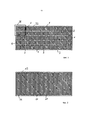
Фиг. 1 - схематически вид сверху составного слоя, содержащего множество элементов из намагничиваемого материала, которые расположены рядами и колоннами на поддерживающем слое,FIG. 1 is a schematic top view of a composite layer containing a plurality of magnetizable material elements that are arranged in rows and columns on a support layer,
Фиг. 2 - схематически вид сверху подобно системе, показанной на фиг. 1, причем элементы являются прямоугольными элементами, простирающимися от одной стороны системы к противоположной стороне,FIG. 2 is a schematic top view similar to the system shown in FIG. 1, the elements being rectangular elements extending from one side of the system to the opposite side,
Фиг. 3 - увеличенный вид участка системы, показанной на фиг. 1, который помечен штриховой линией III,FIG. 3 is an enlarged view of a portion of the system shown in FIG. 1, which is indicated by dashed line III,
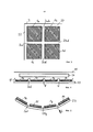
Фиг. 4 - схематическое изображение поперечного сечения системы, включая поверхность полосы движения или дороги, по которой транспортное средство может перемещаться или стоять, встроенную проводниковую структуру первичной стороны и составной слой, подобный слою, показанному на фиг. 1, иFIG. 4 is a schematic cross-sectional view of a system, including the surface of a lane or road along which a vehicle can move or stand, an integrated conductor structure of a primary side, and a composite layer similar to that shown in FIG. 1 and
Фиг. 5 - составной слой из фиг. 4, причем слой слегка сложен вдоль трех прямых зазоров между элементами.FIG. 5 is a composite layer of FIG. 4, the layer being slightly folded along three straight gaps between the elements.
Показанная на фиг. 1 система содержит в общей сложности шестьдесят элементов из намагничиваемого материала, некоторые из элементов обозначены через 1. Элементы 1 расположены колоннами, по пять элементов 1 в каждом случае, и рядами, по двенадцать элементов 1 в каждом случае. Число элементов на колонну или ряд является только примером, может изменяться и на практике зависит от желательной конфигурации, прежде всего от желательных размеров слоя.Shown in FIG. 1, the system contains a total of sixty elements of magnetizable material, some of the elements are indicated by 1.
Между каждой парой соседних элементов 1 имеется некоторое расстояние (см. также фиг. 3), так что между соседними элементами 1 имеются соответствующие зазоры, эти зазоры свободны от намагничиваемого материала. На практике эти зазоры могут быть совсем свободными от материала или могут, по меньшей мере частично, содержать другой (не намагничиваемый) материал.There is a certain distance between each pair of neighboring elements 1 (see also Fig. 3), so that there are corresponding gaps between
Под элементами 1 имеется поддерживающий слой 3. Как также показано на фиг. 3, контур поддерживающего слоя 3 простирается на расстояние 22 от кромок элементов 1a, 1b, 1с, которые расположены вблизи контура поддерживающего слоя 3.Under the
Зазоры между двумя соседними элементами 1, например между элементом 1а и элементом 1с, обозначены ссылочным обозначением 2 и буквой, которая используется для обозначения соседних элементов (например, зазор между соседними элементами 1а, 1с обозначен на фиг. 3 через 2а, 2с). Зазоры выровнены для образования прямых непрерывных зазоров. Прежде всего, зазоры между всеми парами соседних элементов 1 имеют одинаковую ширину (то есть расстояние между соседними элементами одинаково).The gaps between two
Например, в случае варианта осуществления, показанного на фиг. 1, длины (в горизонтальном направлении фиг. 1) и ширины (в вертикальном направлении фиг. 1) элементов 1 могут быть одинаковыми и могут доходить до 10 см. В этом случае расстояние между любыми двумя соседними элементами 1 поперек соответствующего зазора 2 может быть, например, в диапазоне от 0,75 до 1,25 см, предпочтительно в диапазоне от 0,9 до 1,1 см и достигать 1 см.For example, in the case of the embodiment shown in FIG. 1, the lengths (in the horizontal direction of FIG. 1) and the widths (in the vertical direction of FIG. 1) of the
Как будет описано в связи с фиг. 5, поддерживающий слой может быть сложен вдоль непрерывных прямых зазоров. Это также возможно с измененными структурами, показанными на фиг. 2, хотя этот вид составного слоя не является предпочтительным. Элементы 11 структуры, показанные на фиг. 2, шире в боковом направлении (вертикальное направление на фиг. 2) по сравнению со структурой, показанной на фиг. 1. Отдельные элементы 11 простираются от одной стороны в боковом направлении к противоположной стороне в боковом направлении. Поддерживающий слой под элементами 11 обозначен через 13.As will be described in connection with FIG. 5, the support layer can be folded along continuous straight gaps. This is also possible with the modified structures shown in FIG. 2, although this kind of composite layer is not preferred. The
Например, в случае варианта осуществления, показанного на фиг. 2, длина (в горизонтальном направлении на фиг. 1) элементов 11 может быть одинакова и может доходить до 10 см. В этом случае расстояние между любыми соседними элементами 11 поперек соответствующих зазоров может быть, например, в диапазоне от 0,85 до 1,35 см, предпочтительно в диапазоне от 1,0 до 1,2 см, и может доходить до 1,1 см.For example, in the case of the embodiment shown in FIG. 2, the length (in the horizontal direction in FIG. 1) of the
Иначе, чем показано на фиг. 1 и 2, расстояние может быть расстоянием между контурами поддерживающего слоя 3; 13 и кромками элементов 1; 11, если смотреть сверху.Otherwise than shown in FIG. 1 and 2, the distance may be the distance between the contours of the
Поперечное сечение, показанное на фиг. 4, может быть интерпретировано другим образом. В одном случае горизонтальное направление на фиг. 4 простирается в продольном направлении, так что направление, перпендикулярное плоскости изображения на фиг. 4, является боковым направлением. В этом случае число элементов 1e, 1f, 1g, 1h предпочтительно не является суммарным числом последовательно расположенных элементов из намагничиваемого материала, которые расположены в продольном направлении один за другим.The cross section shown in FIG. 4 may be interpreted in another way. In one case, the horizontal direction in FIG. 4 extends in the longitudinal direction, so that a direction perpendicular to the image plane in FIG. 4 is a lateral direction. In this case, the number of
Согласно другой интерпретации фиг. 4, горизонтальное направление на фигуре является боковым направлением, так что продольное направление формирующего поля слоя проходит перпендикулярно плоскости изображения на фиг. 4. В этом случае число четырех элементов 1e, 1f, 1g, 1h, которые расположены рядом последовательным образом, может быть суммарным числом элементов (однако на практике может быть больше расположенных последовательно элементов в боковом направлении или меньше). В любом случае элементы 1 поддерживаются поддерживающим слоем 23. Прежде всего, элементы 1 могут быть прикреплены к верхней поверхности поддерживающего слоя 23, например, с использованием клея. Клей не показан, и вследствие присутствия клея элементы 1 могут быть расположены на расстоянии (например, в несколько мм) в вертикальном направлении, то есть выше верхней поверхности поддерживающего слоя.According to another interpretation of FIG. 4, the horizontal direction in the figure is a lateral direction, so that the longitudinal direction of the forming field of the layer extends perpendicular to the image plane in FIG. 4. In this case, the number of four
На расстоянии над верхней поверхностью элементов 1 расположена проводниковая структура первичной стороны, которая создает - во время работы - электромагнитное поле, которое должно приниматься приемным устройством транспортного средства (не показано). В примере на фиг. 4 проводниковая структура 26 первичной стороны погружена в почву или встроена в полосу движения транспортного средства, и поверхность полосы движения обозначена через 25.At a distance above the upper surface of the
Ход некоторых линий F магнитной индукции показан на фиг. 4. Однако показаны только участки линий F магнитной индукции в области элементов 1. Линии F магнитной индукции изогнуты вдоль их протяжения от областей выше элементов 1, поскольку намагничиваемый материал элементов 1 изменяет направление линий F магнитной индукции, чтобы следовать протяжению намагничиваемого материала. Показанные линии F магнитной индукции являются только примером. Другие линии магнитной индукции могут входить в материал элементов 1 в другом месте, например на верхней поверхности элемента 1.The course of some magnetic induction lines F is shown in FIG. 4. However, only portions of the magnetic induction lines F in the region of the
Горизонтальная протяженность формирующего поле слоя согласно иллюстрациям на фиг. 1 - фиг. 4 является предпочтительным, но не единственным способом использования формирующего поле слоя в связи с проводниковой структурой первичной стороны. Например, формирующий поле слой или дополнительный формирующий поле слой может быть наклоненным относительно горизонтальной плоскости и/или может быть расположен в боковом направлении от проводниковой структуры первичной стороны. Также возможно, что такой же составной слой, содержащий поддерживающий слой и элементы, прикрепленные к поддерживающему слою, может простираться снизу и сбоку (в боковом направлении) от проводниковой структуры первичной стороны.The horizontal extent of the field-forming layer according to the illustrations in FIG. 1 - FIG. 4 is a preferred, but not the only way to use a field-forming layer in connection with the primary side conductor structure. For example, a field-forming layer or an additional field-forming layer may be inclined relative to the horizontal plane and / or may be located laterally from the conductor structure of the primary side. It is also possible that the same composite layer containing the support layer and the elements attached to the support layer can extend from below and from the side (in the lateral direction) from the conductor structure of the primary side.
На фиг. 5 показано, что, например, составной слой 23, 1e-1h на фиг. 4, может быть сложен вдоль зазоров между соседними элементами 1. В состоянии, показанном на фиг. 5, составной слой сложен вдоль каждого из трех зазоров 2ef, 2fg, 2gh. Угол сгиба, показанный на фиг. 5, составляет 20 градусов, однако в зависимости от гибкости поддерживающего слоя 23 и в зависимости от ширины соответствующего зазора между соседними элементами 1 угол сгиба может быть больше. Например, система, показанная на фиг. 5, может быть сложена с образованием катушки или с образованием участков слоя, которые уложены стопкой друг над другом.In FIG. 5 shows that, for example, the
Claims (15)
Applications Claiming Priority (3)
| Application Number | Priority Date | Filing Date | Title |
|---|---|---|---|
| GB1208508.0A GB2502084A (en) | 2012-05-14 | 2012-05-14 | Arrangement for providing vehicles with energy comprising magnetisable material |
| GB1208508.0 | 2012-05-14 | ||
| PCT/EP2013/059952 WO2013171220A1 (en) | 2012-05-14 | 2013-05-14 | Arrangement for providing vehicles with energy comprising magnetizable material |
Publications (2)
| Publication Number | Publication Date |
|---|---|
| RU2014150421A RU2014150421A (en) | 2016-07-10 |
| RU2637496C2 true RU2637496C2 (en) | 2017-12-05 |
Family
ID=46458845
Family Applications (1)
| Application Number | Title | Priority Date | Filing Date |
|---|---|---|---|
| RU2014150421A RU2637496C2 (en) | 2012-05-14 | 2013-05-14 | System for providing vehicle with energy containing magnetizable material |
Country Status (14)
| Country | Link |
|---|---|
| US (2) | US9793040B2 (en) |
| EP (1) | EP2850625B1 (en) |
| JP (1) | JP6328615B2 (en) |
| KR (1) | KR102007942B1 (en) |
| CN (1) | CN104350557B (en) |
| AU (1) | AU2013261800A1 (en) |
| BR (1) | BR112014027822A2 (en) |
| CA (1) | CA2872151C (en) |
| GB (1) | GB2502084A (en) |
| HK (1) | HK1208757A1 (en) |
| IN (1) | IN2014DN09615A (en) |
| RU (1) | RU2637496C2 (en) |
| SG (1) | SG11201407333YA (en) |
| WO (1) | WO2013171220A1 (en) |
Families Citing this family (8)
| Publication number | Priority date | Publication date | Assignee | Title |
|---|---|---|---|---|
| GB2516854A (en) | 2013-08-01 | 2015-02-11 | Bombardier Transp Gmbh | Carrying device and a receiving device |
| US20170063169A1 (en) * | 2015-08-26 | 2017-03-02 | Qualcomm Incorporated | Receiver detuning compensation using transmitter ferrite |
| DE102016205352A1 (en) * | 2016-03-31 | 2017-10-05 | Bayerische Motoren Werke Aktiengesellschaft | Primary coil unit |
| GB2551990A (en) | 2016-07-04 | 2018-01-10 | Bombardier Primove Gmbh | Transferring energy by magnetic induction using a primary unit conductor arrangement and a layer comprising magnetic and/or magnetizable material |
| DE102017211208A1 (en) * | 2017-06-30 | 2019-01-03 | Bayerische Motoren Werke Aktiengesellschaft | Coil device for a motor vehicle, in particular for a motor vehicle |
| CN113678214A (en) * | 2019-05-03 | 2021-11-19 | 波莫卡公司 | Multipole magnetising device for high coercivity materials |
| CN111277109B (en) * | 2020-03-11 | 2021-02-23 | 中车青岛四方机车车辆股份有限公司 | Magnetic-levitation train linear motor and magnetic-levitation train |
| DE102020209282A1 (en) | 2020-07-23 | 2022-01-27 | Mahle International Gmbh | Induction assembly of an inductive charging device |
Citations (5)
| Publication number | Priority date | Publication date | Assignee | Title |
|---|---|---|---|---|
| US4118704A (en) * | 1976-04-07 | 1978-10-03 | Tdk Electronics Co., Ltd. | Electromagnetic wave-absorbing wall |
| WO2006129704A1 (en) * | 2005-06-03 | 2006-12-07 | Murata Manufacturing Co., Ltd. | Ferrite sheet and process for producing the same |
| RU2408124C1 (en) * | 2009-01-27 | 2010-12-27 | Панасоник Электрик Воркс Ко., Лтд. | System of contactless transfer of power |
| WO2011016737A1 (en) * | 2009-08-07 | 2011-02-10 | Auckland Uniservices Limited | Inductive power transfer system |
| RU2010111552A (en) * | 2007-08-28 | 2011-10-10 | Эксесс Бизнесс Груп Интернешнл ЛЛС (US) | INDUCTIVE POWER SUPPLY |
Family Cites Families (21)
| Publication number | Priority date | Publication date | Assignee | Title |
|---|---|---|---|---|
| JPH0729677Y2 (en) * | 1990-03-14 | 1995-07-05 | 鐘淵化学工業株式会社 | Ferrite sheet for magnetic field correction of deflection yoke |
| JP2003045731A (en) * | 2001-07-30 | 2003-02-14 | Nec Tokin Corp | Non-contact power transmission apparatus |
| JP4852829B2 (en) * | 2004-07-28 | 2012-01-11 | セイコーエプソン株式会社 | Non-contact power transmission device |
| CN101213896A (en) * | 2005-07-07 | 2008-07-02 | 株式会社村田制作所 | Ferrite sheet |
| WO2008026080A2 (en) * | 2006-09-01 | 2008-03-06 | Bio Aim Technologies Holding Ltd. | Systems and methods for wireless power transfer |
| DE102006048829B4 (en) * | 2006-10-11 | 2016-05-25 | Thyssenkrupp Transrapid Gmbh | Receiving unit with a receiver coil for non-contact transmission of electrical energy and method for their preparation |
| JP4209437B2 (en) * | 2006-11-10 | 2009-01-14 | 三菱重工業株式会社 | Non-contact power feeding device for mobile body and protection device therefor |
| JP2009200174A (en) * | 2008-02-20 | 2009-09-03 | Panasonic Electric Works Co Ltd | Non-contact power transmission apparatus |
| GB2461577A (en) | 2008-07-04 | 2010-01-06 | Bombardier Transp Gmbh | System and method for transferring electric energy to a vehicle |
| JP2010041906A (en) * | 2008-07-10 | 2010-02-18 | Nec Tokin Corp | Contactless power transmission apparatus, soft magnetic sheet, and module using the same |
| JP5150476B2 (en) * | 2008-12-22 | 2013-02-20 | 株式会社東芝 | ANTENNA DEVICE AND RADIO DEVICE |
| KR100944113B1 (en) * | 2009-02-27 | 2010-02-24 | 한국과학기술원 | Power supply system and method for electric vehicle |
| KR101040662B1 (en) * | 2009-04-06 | 2011-06-13 | 한국과학기술원 | Ultra slim power supply and collector device for electric vehicle |
| JP5077340B2 (en) * | 2009-12-25 | 2012-11-21 | トヨタ自動車株式会社 | Non-contact power receiving apparatus and manufacturing method thereof |
| KR101087768B1 (en) * | 2010-05-26 | 2011-11-30 | 한국과학기술원 | Emi cancellation device in power supply and collector device for magnetic induction power transmission |
| KR101156034B1 (en) * | 2010-07-15 | 2012-06-18 | 한국과학기술원 | Method and apparatus for designing power supply system and collector device for online electric vehicle |
| JP5593977B2 (en) * | 2010-09-01 | 2014-09-24 | Nok株式会社 | Non-contact power feeding device |
| JP5632089B2 (en) * | 2010-10-29 | 2014-11-26 | クアルコム,インコーポレイテッド | Wireless energy transfer through coupled parasitic resonators |
| US20120218068A1 (en) * | 2011-02-28 | 2012-08-30 | Equos Research Co., Ltd. | Antenna |
| JP5177267B2 (en) * | 2011-09-01 | 2013-04-03 | パナソニック株式会社 | Magnetic sheet |
| US9431834B2 (en) * | 2012-03-20 | 2016-08-30 | Qualcomm Incorporated | Wireless power transfer apparatus and method of manufacture |
-
2012
- 2012-05-14 GB GB1208508.0A patent/GB2502084A/en not_active Withdrawn
-
2013
- 2013-05-14 AU AU2013261800A patent/AU2013261800A1/en not_active Abandoned
- 2013-05-14 CN CN201380025261.2A patent/CN104350557B/en active Active
- 2013-05-14 SG SG11201407333YA patent/SG11201407333YA/en unknown
- 2013-05-14 JP JP2015512036A patent/JP6328615B2/en not_active Expired - Fee Related
- 2013-05-14 RU RU2014150421A patent/RU2637496C2/en not_active IP Right Cessation
- 2013-05-14 WO PCT/EP2013/059952 patent/WO2013171220A1/en active Application Filing
- 2013-05-14 US US14/400,015 patent/US9793040B2/en active Active
- 2013-05-14 EP EP13722453.1A patent/EP2850625B1/en active Active
- 2013-05-14 CA CA2872151A patent/CA2872151C/en not_active Expired - Fee Related
- 2013-05-14 BR BR112014027822A patent/BR112014027822A2/en not_active IP Right Cessation
- 2013-05-14 KR KR1020147035048A patent/KR102007942B1/en active IP Right Grant
-
2014
- 2014-11-14 IN IN9615DEN2014 patent/IN2014DN09615A/en unknown
-
2015
- 2015-09-23 HK HK15109336.7A patent/HK1208757A1/en unknown
-
2017
- 2017-09-25 US US15/714,274 patent/US20180025827A1/en not_active Abandoned
Patent Citations (5)
| Publication number | Priority date | Publication date | Assignee | Title |
|---|---|---|---|---|
| US4118704A (en) * | 1976-04-07 | 1978-10-03 | Tdk Electronics Co., Ltd. | Electromagnetic wave-absorbing wall |
| WO2006129704A1 (en) * | 2005-06-03 | 2006-12-07 | Murata Manufacturing Co., Ltd. | Ferrite sheet and process for producing the same |
| RU2010111552A (en) * | 2007-08-28 | 2011-10-10 | Эксесс Бизнесс Груп Интернешнл ЛЛС (US) | INDUCTIVE POWER SUPPLY |
| RU2408124C1 (en) * | 2009-01-27 | 2010-12-27 | Панасоник Электрик Воркс Ко., Лтд. | System of contactless transfer of power |
| WO2011016737A1 (en) * | 2009-08-07 | 2011-02-10 | Auckland Uniservices Limited | Inductive power transfer system |
Also Published As
| Publication number | Publication date |
|---|---|
| KR102007942B1 (en) | 2019-10-21 |
| CA2872151C (en) | 2019-04-30 |
| US20180025827A1 (en) | 2018-01-25 |
| AU2013261800A1 (en) | 2014-11-20 |
| CN104350557B (en) | 2017-08-22 |
| EP2850625B1 (en) | 2019-07-03 |
| BR112014027822A2 (en) | 2017-06-27 |
| JP2015525462A (en) | 2015-09-03 |
| JP6328615B2 (en) | 2018-05-23 |
| CN104350557A (en) | 2015-02-11 |
| IN2014DN09615A (en) | 2015-07-31 |
| KR20150013781A (en) | 2015-02-05 |
| US9793040B2 (en) | 2017-10-17 |
| WO2013171220A1 (en) | 2013-11-21 |
| GB2502084A (en) | 2013-11-20 |
| US20150137933A1 (en) | 2015-05-21 |
| CA2872151A1 (en) | 2013-11-21 |
| SG11201407333YA (en) | 2014-12-30 |
| GB201208508D0 (en) | 2012-06-27 |
| RU2014150421A (en) | 2016-07-10 |
| EP2850625A1 (en) | 2015-03-25 |
| HK1208757A1 (en) | 2016-03-11 |
Similar Documents
| Publication | Publication Date | Title |
|---|---|---|
| RU2637496C2 (en) | System for providing vehicle with energy containing magnetizable material | |
| US9517697B2 (en) | Providing a vehicle with electric energy using a receiving device adapted to receive an alternating electromagnetic field | |
| US8528710B2 (en) | Mobile type non-contact power feeding device | |
| RU2613625C2 (en) | Providing transport vehicle, particularly rail vehicle or road car, with electrical energy by induction | |
| JP5957976B2 (en) | Contactless power supply | |
| AU2013254791A1 (en) | Providing a land vehicle, in particular a rail vehicle or a road automobile, with electric energy by induction | |
| US9688157B2 (en) | Providing vehicles with electric energy by magnetic induction | |
| GB2502820A (en) | Inductive power coupling for rail-guided electric vehicles |
Legal Events
| Date | Code | Title | Description |
|---|---|---|---|
| MM4A | The patent is invalid due to non-payment of fees |
Effective date: 20190515 |