RU2597136C2 - Flexible tether with integrated sensors for dynamic instrument tracking - Google Patents
Flexible tether with integrated sensors for dynamic instrument tracking Download PDFInfo
- Publication number
- RU2597136C2 RU2597136C2 RU2013120967/14A RU2013120967A RU2597136C2 RU 2597136 C2 RU2597136 C2 RU 2597136C2 RU 2013120967/14 A RU2013120967/14 A RU 2013120967/14A RU 2013120967 A RU2013120967 A RU 2013120967A RU 2597136 C2 RU2597136 C2 RU 2597136C2
- Authority
- RU
- Russia
- Prior art keywords
- tool
- cable
- instrument
- optical
- shape
- Prior art date
Links
- 238000003384 imaging method Methods 0.000 claims abstract description 57
- 230000003287 optical effect Effects 0.000 claims abstract description 46
- 238000000034 method Methods 0.000 claims abstract description 30
- 239000000835 fiber Substances 0.000 claims description 51
- 239000003550 marker Substances 0.000 claims description 17
- 238000012800 visualization Methods 0.000 claims description 17
- 239000013307 optical fiber Substances 0.000 claims description 15
- 238000005259 measurement Methods 0.000 claims description 13
- 238000001574 biopsy Methods 0.000 claims description 11
- 238000004806 packaging method and process Methods 0.000 claims description 9
- 238000009607 mammography Methods 0.000 claims description 5
- 238000012545 processing Methods 0.000 claims description 4
- 210000003484 anatomy Anatomy 0.000 abstract description 7
- 230000000694 effects Effects 0.000 abstract description 2
- 239000000126 substance Substances 0.000 abstract 1
- 238000013152 interventional procedure Methods 0.000 description 8
- 230000005855 radiation Effects 0.000 description 8
- 238000013459 approach Methods 0.000 description 7
- 238000002591 computed tomography Methods 0.000 description 7
- 238000004364 calculation method Methods 0.000 description 6
- 238000002595 magnetic resonance imaging Methods 0.000 description 6
- 238000001356 surgical procedure Methods 0.000 description 5
- 239000000853 adhesive Substances 0.000 description 4
- 230000001070 adhesive effect Effects 0.000 description 4
- 210000001519 tissue Anatomy 0.000 description 4
- 206010028980 Neoplasm Diseases 0.000 description 3
- 238000004422 calculation algorithm Methods 0.000 description 3
- 230000008859 change Effects 0.000 description 3
- 238000002594 fluoroscopy Methods 0.000 description 3
- 239000000463 material Substances 0.000 description 3
- 238000002604 ultrasonography Methods 0.000 description 3
- 230000008901 benefit Effects 0.000 description 2
- 238000005253 cladding Methods 0.000 description 2
- 238000013170 computed tomography imaging Methods 0.000 description 2
- 238000002788 crimping Methods 0.000 description 2
- 238000010586 diagram Methods 0.000 description 2
- 238000005516 engineering process Methods 0.000 description 2
- 210000005075 mammary gland Anatomy 0.000 description 2
- 238000002310 reflectometry Methods 0.000 description 2
- 230000004044 response Effects 0.000 description 2
- 230000003595 spectral effect Effects 0.000 description 2
- 238000001228 spectrum Methods 0.000 description 2
- 238000011477 surgical intervention Methods 0.000 description 2
- 208000003174 Brain Neoplasms Diseases 0.000 description 1
- 0 CC*(CC)CCCC1CCCC1 Chemical compound CC*(CC)CCCC1CCCC1 0.000 description 1
- 230000005540 biological transmission Effects 0.000 description 1
- 210000004204 blood vessel Anatomy 0.000 description 1
- 210000000481 breast Anatomy 0.000 description 1
- 238000010276 construction Methods 0.000 description 1
- 238000002059 diagnostic imaging Methods 0.000 description 1
- 238000003780 insertion Methods 0.000 description 1
- 230000037431 insertion Effects 0.000 description 1
- 230000005865 ionizing radiation Effects 0.000 description 1
- 239000002184 metal Substances 0.000 description 1
- 239000000203 mixture Substances 0.000 description 1
- 231100000915 pathological change Toxicity 0.000 description 1
- 230000036285 pathological change Effects 0.000 description 1
- 238000003909 pattern recognition Methods 0.000 description 1
- 230000035515 penetration Effects 0.000 description 1
- 230000008569 process Effects 0.000 description 1
- 239000000523 sample Substances 0.000 description 1
- 230000035945 sensitivity Effects 0.000 description 1
- 230000000451 tissue damage Effects 0.000 description 1
- 231100000827 tissue damage Toxicity 0.000 description 1
- 230000007704 transition Effects 0.000 description 1
Images


Classifications
-
- A—HUMAN NECESSITIES
- A61—MEDICAL OR VETERINARY SCIENCE; HYGIENE
- A61B—DIAGNOSIS; SURGERY; IDENTIFICATION
- A61B5/00—Measuring for diagnostic purposes; Identification of persons
- A61B5/0033—Features or image-related aspects of imaging apparatus classified in A61B5/00, e.g. for MRI, optical tomography or impedance tomography apparatus; arrangements of imaging apparatus in a room
- A61B5/0036—Features or image-related aspects of imaging apparatus classified in A61B5/00, e.g. for MRI, optical tomography or impedance tomography apparatus; arrangements of imaging apparatus in a room including treatment, e.g., using an implantable medical device, ablating, ventilating
-
- A—HUMAN NECESSITIES
- A61—MEDICAL OR VETERINARY SCIENCE; HYGIENE
- A61B—DIAGNOSIS; SURGERY; IDENTIFICATION
- A61B34/00—Computer-aided surgery; Manipulators or robots specially adapted for use in surgery
- A61B34/20—Surgical navigation systems; Devices for tracking or guiding surgical instruments, e.g. for frameless stereotaxis
-
- A—HUMAN NECESSITIES
- A61—MEDICAL OR VETERINARY SCIENCE; HYGIENE
- A61B—DIAGNOSIS; SURGERY; IDENTIFICATION
- A61B6/00—Apparatus or devices for radiation diagnosis; Apparatus or devices for radiation diagnosis combined with radiation therapy equipment
- A61B6/44—Constructional features of apparatus for radiation diagnosis
- A61B6/4494—Means for identifying the diagnostic device
-
- A—HUMAN NECESSITIES
- A61—MEDICAL OR VETERINARY SCIENCE; HYGIENE
- A61B—DIAGNOSIS; SURGERY; IDENTIFICATION
- A61B90/00—Instruments, implements or accessories specially adapted for surgery or diagnosis and not covered by any of the groups A61B1/00 - A61B50/00, e.g. for luxation treatment or for protecting wound edges
- A61B90/90—Identification means for patients or instruments, e.g. tags
- A61B90/98—Identification means for patients or instruments, e.g. tags using electromagnetic means, e.g. transponders
-
- A—HUMAN NECESSITIES
- A61—MEDICAL OR VETERINARY SCIENCE; HYGIENE
- A61B—DIAGNOSIS; SURGERY; IDENTIFICATION
- A61B17/00—Surgical instruments, devices or methods, e.g. tourniquets
- A61B17/34—Trocars; Puncturing needles
- A61B17/3478—Endoscopic needles, e.g. for infusion
-
- A—HUMAN NECESSITIES
- A61—MEDICAL OR VETERINARY SCIENCE; HYGIENE
- A61B—DIAGNOSIS; SURGERY; IDENTIFICATION
- A61B34/00—Computer-aided surgery; Manipulators or robots specially adapted for use in surgery
- A61B34/20—Surgical navigation systems; Devices for tracking or guiding surgical instruments, e.g. for frameless stereotaxis
- A61B2034/2046—Tracking techniques
- A61B2034/2061—Tracking techniques using shape-sensors, e.g. fiber shape sensors with Bragg gratings
-
- A—HUMAN NECESSITIES
- A61—MEDICAL OR VETERINARY SCIENCE; HYGIENE
- A61B—DIAGNOSIS; SURGERY; IDENTIFICATION
- A61B90/00—Instruments, implements or accessories specially adapted for surgery or diagnosis and not covered by any of the groups A61B1/00 - A61B50/00, e.g. for luxation treatment or for protecting wound edges
- A61B90/36—Image-producing devices or illumination devices not otherwise provided for
- A61B90/37—Surgical systems with images on a monitor during operation
- A61B2090/376—Surgical systems with images on a monitor during operation using X-rays, e.g. fluoroscopy
- A61B2090/3762—Surgical systems with images on a monitor during operation using X-rays, e.g. fluoroscopy using computed tomography systems [CT]
- A61B2090/3764—Surgical systems with images on a monitor during operation using X-rays, e.g. fluoroscopy using computed tomography systems [CT] with a rotating C-arm having a cone beam emitting source
Landscapes
- Health & Medical Sciences (AREA)
- Life Sciences & Earth Sciences (AREA)
- Surgery (AREA)
- Engineering & Computer Science (AREA)
- Medical Informatics (AREA)
- Public Health (AREA)
- General Health & Medical Sciences (AREA)
- Animal Behavior & Ethology (AREA)
- Biomedical Technology (AREA)
- Heart & Thoracic Surgery (AREA)
- Veterinary Medicine (AREA)
- Molecular Biology (AREA)
- Nuclear Medicine, Radiotherapy & Molecular Imaging (AREA)
- Pathology (AREA)
- Physics & Mathematics (AREA)
- Biophysics (AREA)
- Radiology & Medical Imaging (AREA)
- High Energy & Nuclear Physics (AREA)
- Optics & Photonics (AREA)
- Electromagnetism (AREA)
- Oral & Maxillofacial Surgery (AREA)
- Robotics (AREA)
- Endoscopes (AREA)
- Apparatus For Radiation Diagnosis (AREA)
Abstract
Description
Изобретение относится к области медицинской визуализации, а именно к отслеживанию функциональной части инструмента и обеспечению динамической визуализации, относящейся к функциональной части инструмента.The invention relates to the field of medical imaging, namely to tracking the functional part of the instrument and providing dynamic visualization related to the functional part of the instrument.
Системы визуализации все чаще используются для направления инструментов при хирургических вмешательствах. В современной практике объемная визуализация, выполняемая с использованием таких средств, как магнитно-резонансная визуализация (MRI), компьютерная томография (CT) или XperCT (например, прямые флуороскопические изображения, совмещенные с CT-изображениями, полученными плоским детектором), может использоваться для идентификации местонахождения целевых тканей до операции и для идентификации чувствительных тканей вокруг мишеней, чтобы свести к минимуму осложнения в результате побочных повреждений тканей. Эти объемы изображений могут быть получены с использованием иных средств, чем те, что используются для направления инструментов, применяемых при операции в режиме реального времени. Например, CT может использоваться для предоперационной визуализации, а ультразвук может использоваться для контроля направления на основе изображений в реальном времени.Imaging systems are increasingly used to guide instruments in surgical interventions. In modern practice, volumetric imaging performed using tools such as magnetic resonance imaging (MRI), computed tomography (CT), or XperCT (for example, direct fluoroscopic images combined with CT images obtained by a flat detector) can be used to identify location of target tissues prior to surgery and to identify sensitive tissues around targets to minimize complications resulting from collateral tissue damage. These volumes of images can be obtained using other means than those used to guide the tools used in real-time surgery. For example, CT can be used for preoperative imaging, and ultrasound can be used to control direction based on real-time images.
Точное определение местонахождения функциональных частей инструментов (например, лезвия скальпеля) относительно структур, идентифицированных на предоперационных изображениях, принципиально важно для врачей. Часто имеется лишь ограниченная информация для направления на основе изображений в реальном времени. Доступная информация может быть ограничена из-за того, что использование визуализирующих технологий сведено к минимуму (например, для снижения дозы ионизирующего облучения, которому подвергается пациент при проведении рентгеновской флуороскопии). Доступная информация может быть также ограничена вследствие ограничений, присущих визуализирующей технологии (например, отсутствие контраста для некоторых патологических изменений при проведении ультразвукового исследования). Следовательно, врачи часто испытывают неуверенность по поводу местонахождения инструментов относительно анатомических структур, выявленных в объемах изображений. Эта неопределенность может приводить к повышению рисков для пациентов, а также к увеличению расходов при проведении операций.Accurate location of the functional parts of instruments (for example, a scalpel blade) relative to the structures identified on preoperative images is crucial for doctors. Often there is only limited information for direction based on real-time images. Available information may be limited due to the fact that the use of imaging technologies is minimized (for example, to reduce the dose of ionizing radiation to which a patient is exposed during X-ray fluoroscopy). Available information may also be limited due to limitations inherent in imaging technology (for example, lack of contrast for some pathological changes during ultrasound examination). Consequently, doctors often experience uncertainty about the location of instruments relative to the anatomical structures identified in the image volumes. This uncertainty can lead to increased risks for patients, as well as to increased costs during operations.
Предложен ряд подходов для отслеживания инструмента, основанных на использовании маркеров. Один из таких подходов на основе использования маркеров - оптическое отслеживание. При оптическом отслеживании маркеры располагают на инструменте так, что они визуально доступны с помощью оптических детекторов. При применении этого способа объекты, которые блокируют, делают неразборчивым или как-то иначе ограничивают поле обзора и обзорный луч детекторов, могут сделать алгоритм непригодным или снизить его возможности по отслеживанию.A number of approaches for tracking tools based on the use of markers are proposed. One of these marker-based approaches is optical tracking. In optical tracking, markers are positioned on the instrument so that they are visually accessible with optical detectors. When using this method, objects that block, make it illegible or otherwise restrict the field of view and the viewing beam of detectors can make the algorithm unusable or reduce its tracking capabilities.
Другой подход на основе использования маркеров - электромагнитный (EM) контроль направления. Этот способ требует расположения EM-датчиков на инструменте. Хотя проблемы с линией прямой видимости, имеющие место при оптическом отслеживании, к этому способу не относятся, точность и тщательность отслеживания могут снижаться под действием внешних EM-полей вследствие пространственно-временного изменения электромагнитного пространства.Another marker-based approach is electromagnetic (EM) direction control. This method requires the location of EM sensors on the instrument. Although the problems with the line of sight that occur during optical tracking are not relevant to this method, the accuracy and accuracy of tracking can be reduced by external EM fields due to the spatio-temporal change in the electromagnetic space.
В обоих вышеупомянутых подходах к отслеживанию на основе использования маркеров положение маркеров должно совмещаться с системой координат объемов изображений. Ошибки могут возникать в тех случаях, когда между этими координатными системами присутствует неточность совмещения. Неточность совмещения может возникать, например, когда EM-система незначительно перемещается в пределах помещения.In both of the aforementioned approaches to tracking based on the use of markers, the position of the markers should be combined with the coordinate system of the image volumes. Errors can occur when there is an inaccuracy of alignment between these coordinate systems. Inaccurate alignment can occur, for example, when the EM system moves slightly indoors.
Еще один подход заключается в использовании оптического измерения формы для определения формы удлиненного гибкого инструмента, такого как катетер, в пределах анатомической структуры. Оптическое измерение формы в данном контексте предполагает подачу светового излучения в оптоволоконные сердцевины, расположенные в инструменте, и сбор светового излучения из оптоволоконных сердцевин, расположенных в инструменте; сигналы, принадлежащие собранному световому излучению, обрабатываются, чтобы сделать заключение о форме или аспектах формы инструмента. Оптическое измерение формы, например, может включать обратное рассеяние от волоконных брэгговских решеток (FBG), а также рэлеевских рассеивателей в сердцевине или оболочке оптических волокон. Это измерение формы описывается в сочетании с подходом на основе использования маркеров. При данном подходе маркер помещают на инструмент для отслеживания местонахождения инструмента, при этом оптическое измерение формы используется для определения формы инструмента в пределах анатомической структуры.Another approach is to use optical shape measurement to determine the shape of an elongated flexible instrument, such as a catheter, within the anatomical structure. Optical shape measurement in this context involves the supply of light radiation to the fiber optic cores located in the tool, and the collection of light radiation from the fiber optic cores located in the tool; signals belonging to the collected light radiation are processed to make a conclusion about the shape or aspects of the shape of the instrument. Optical shape measurement, for example, may include backscattering from fiber Bragg gratings (FBGs) as well as Rayleigh scatterers in the core or cladding of optical fibers. This shape measurement is described in combination with a marker-based approach. With this approach, a marker is placed on the instrument to track the location of the instrument, while optical shape measurement is used to determine the shape of the instrument within the anatomical structure.
Предложены система и способ для отслеживания функциональной части инструмента в процессе интервенционной процедуры путем определения трехмерной формы кабеля, соединяющего инструмент с системой визуализации, а также отображения динамической визуализации, соответствующей функциональной части инструмента.The proposed system and method for tracking the functional part of the tool during the intervention procedure by determining the three-dimensional shape of the cable connecting the tool with the visualization system, as well as display dynamic visualization corresponding to the functional part of the tool.
Согласно одному варианту осуществления система содержит: по меньшей мере, один инструмент; систему для получения анатомических изображений, относящихся к направлению инструмента; кабель, соединенный с системой визуализации на зафиксированном конце, соединенный с инструментом на дистальном конце, и содержащий, по меньшей мере, одно продольное оптическое волокно с множеством оптических датчиков, содержащих оптоволоконные сердцевины с источниками рассеяния, такими как волоконные брэгговские решетки или рэлеевские рассеиватели; оптическую консоль, выполненную с возможностью опроса датчиков и распознавания отраженного светового излучения, и процессор, выполненный с возможностью расчета локальной кривизны вдоль длины датчиков для определения трехмерной формы кабеля и определения местонахождения и ориентации инструмента относительно изображений, используя трехмерную форму кабеля и местонахождение зафиксированного конца кабеля. В одном варианте осуществления имеются четыре сердцевины волокна, при этом одна сердцевина волокна располагается по оси, а другие расположены по спирали вокруг осевой сердцевины волокна. Хотя в настоящем описании изобретение рассматривается применительно к FBG, следует понимать, что можно включить в состав волоконную оптику для измерения формы или определения местонахождения в широком плане, в том числе, например, будь то с FBG или другой оптикой или без них, измерения формы или определения местонахождения из распознавания изменения в одной или более секций волокна, используя обратное рассеяние, измерение силы оптического волокна, датчики местонахождения волокна или рэлеевское рассеяние.According to one embodiment, the system comprises: at least one tool; system for obtaining anatomical images related to the direction of the instrument; a cable connected to the imaging system at the fixed end, connected to the instrument at the distal end, and containing at least one longitudinal optical fiber with a plurality of optical sensors containing fiber optic cores with scattering sources, such as fiber Bragg gratings or Rayleigh diffusers; an optical console configured to interrogate the sensors and recognize the reflected light, and a processor configured to calculate local curvature along the length of the sensors to determine the three-dimensional shape of the cable and determine the location and orientation of the instrument relative to the images using the three-dimensional shape of the cable and the location of the fixed end of the cable. In one embodiment, there are four fiber cores, with one fiber core being axially located, and the others are helical around the axial fiber core. Although the invention is considered with reference to FBG in the present description, it should be understood that fiber optics can be included in the composition for measuring shape or locating broadly, including, for example, whether with or without FBG or other optics, shape measurement or locating from recognizing changes in one or more sections of the fiber using backscatter, measuring the strength of the optical fiber, fiber location sensors, or Rayleigh scattering.
Согласно одному варианту осуществления система визуализации выполнена с возможностью построения трехмерного пространства изображений и отображения соответствующего вида пространства изображений для инструмента, показывая функциональную часть инструмента в пространстве изображений.According to one embodiment, the visualization system is configured to construct a three-dimensional image space and display the corresponding kind of image space for the tool, showing the functional part of the tool in the image space.
В одном варианте осуществления инструмент выбирается из множества инструментов. В данном варианте осуществления система дополнительно содержит блок идентификации инструмента, идентифицирующий инструмент, выбранный из множества инструментов. Блок идентификации может представлять собой RFID-приемник, при этом RFDI-передатчик, идентифицирующий инструмент, расположен на инструменте или на упаковке для инструмента. По альтернативному варианту блок идентификации может представлять собой устройство считывания штрихового кода, при этом штриховой код, идентифицирующий инструмент, расположен на инструменте или на упаковке для инструмента. Согласно следующему альтернативному варианту осуществления блок идентификации представляет собой электрический датчик, при этом электрический сигнал, идентифицирующий инструмент, подается инструментом или упаковкой для инструмента. В еще одном альтернативном варианте осуществления блок идентификации представляет собой клавишную панель для ввода идентификационного индикатора вручную.In one embodiment, a tool is selected from a plurality of tools. In this embodiment, the system further comprises a tool identification unit identifying a tool selected from a plurality of tools. The identification unit may be an RFID receiver, wherein the RFDI transmitter identifying the instrument is located on the instrument or on the instrument packaging. Alternatively, the identification unit may be a barcode reader, with the barcode identifying the tool located on the tool or on the packaging for the tool. According to a further alternative embodiment, the identification unit is an electrical sensor, wherein the electrical signal identifying the tool is supplied by a tool or tool packaging. In yet another alternative embodiment, the identification unit is a keypad for manually entering an identification indicator.
Согласно одному варианту осуществления процессор представляет собой процессор обработки изображений в составе визуализирующей системы.According to one embodiment, the processor is an image processing processor as part of an imaging system.
Согласно одному варианту осуществления инструмент съемно присоединен к дистальному концу кабеля с помощью механического соединения, такого как хомут или резьбовое зацепление. По альтернативному варианту инструмент может быть съемно присоединен к дистальному концу кабеля с помощью магнитного соединения или адгезива.According to one embodiment, the tool is removably attached to the distal end of the cable using a mechanical connection such as a clamp or threaded engagement. Alternatively, the tool may be removably attached to the distal end of the cable using a magnetic connection or adhesive.
Система визуализации может представлять собой XperCT-систему, при этом кабель соединен с корпусом C-образной рамы XperCT-системы. По альтернативному варианту система визуализации может представлять собой комбинированную систему для проведения рентгеновской маммографии молочных желез и взятия биопсии, при этом кабель соединен с источником рентгеновского излучения, детектором рентгеновского излучения или системой для взятия биопсии.The imaging system can be an XperCT system, and the cable is connected to the housing of the C-frame of the XperCT system. Alternatively, the imaging system may be a combined system for performing mammary x-ray mammography and biopsy, the cable being connected to an x-ray source, an x-ray detector, or a biopsy system.
Согласно одному варианту осуществления к системе визуализации присоединены, по меньшей мере, два кабеля. Это позволяет одновременно отслеживать два инструмента.According to one embodiment, at least two cables are connected to the imaging system. This allows you to simultaneously track two instruments.
Согласно одному варианту осуществления на кабеле или на инструменте расположен, по меньшей мере, один маркер для обеспечения референсных точек в режиме реального времени для расчета формы кабеля. Маркер может представлять собой рентгеноконтрастный маркер. По альтернативному варианту маркер может представлять собой электромагнитный или оптический маркер. Оптоволоконные сердцевины встроены в кабель. Предпочтительно имеются четыре оптоволоконные сердцевины, при этом одна сердцевина волокна располагается по оси, а другие расположены по спирали вокруг осевой сердцевины волокна. Следует отметить, что эти четыре сердцевины могут содержаться в единственном волокне (тем самым имея общую оболочку) либо в отдельных волокнах, механически соединенных между собой (например, склеенных).According to one embodiment, at least one marker is located on the cable or on the tool to provide real-time reference points for calculating the shape of the cable. The marker may be a radiopaque marker. Alternatively, the marker may be an electromagnetic or optical marker. Fiber optic cores are integrated in the cable. Preferably, there are four fiber optic cores, with one fiber core lying axially and the other spirally around the axial fiber core. It should be noted that these four cores can be contained in a single fiber (thereby having a common shell) or in separate fibers mechanically interconnected (for example, glued together).
Согласно одному варианту осуществления предложен способ отслеживания функциональной части инструмента и отображения динамической визуализации, соответствующей функциональной части инструмента. Способ содержит этапы, на которых: принимают данные изображения из визуализирующего устройства; строят объем изображения; определяют трехмерную форму гибкого кабеля, имеющего один конец, зафиксированный в известном местоположении относительно визуализирующего устройства, и имеющего соединитель для инструмента, расположенный на противоположном конце; определяют местонахождение функциональной части инструмента, используя известное местоположение зафиксированного конца кабеля, трехмерную форму кабеля и заданные размер и форму инструмента; и отображают динамическое изображение, соответствующее инструменту, и показывают функциональную часть выбранного инструмента в объеме изображения.According to one embodiment, a method is provided for tracking a functional part of a tool and displaying a dynamic visualization corresponding to the functional part of a tool. The method comprises the steps of: receiving image data from an imaging device; Build the volume of the image; determining a three-dimensional shape of a flexible cable having one end fixed at a known location relative to the imaging device and having a tool connector located at the opposite end; determining the location of the functional part of the tool using the known location of the fixed end of the cable, the three-dimensional shape of the cable and the specified size and shape of the tool; and display the dynamic image corresponding to the tool, and show the functional part of the selected tool in the image volume.
Согласно одному варианту осуществления гибкий кабель содержит оптоволоконные сердцевины, расположенные продольно в кабеле. В оптоволоконных сердцевинах или оболочках расположено множество оптических рассеивателей (например, волоконные брэгговские решетки или рэлеевские рассеиватели). Измеряется отражательная способность в различных местоположениях вдоль кабеля. На основе этих измерений разложенной по длине отражающей способности рассчитываются разложенные по длине деформация и кривизна. На основе последних рассчитывается трехмерная форма кабеля.According to one embodiment, the flexible cable comprises fiber optic cores located longitudinally in the cable. Fiber optic cores or shells have a plurality of optical scatterers (e.g., fiber Bragg gratings or Rayleigh scatterers). Reflectivity is measured at various locations along the cable. Based on these measurements of the length-spread reflectivity, the length-strain and curvature are calculated. Based on the latter, a three-dimensional shape of the cable is calculated.
Согласно одному варианту осуществления инструмент выбирается из множества инструментов. Способ по данному варианту осуществления дополнительно содержит этапы, на которых принимают идентифицирующую информацию о выбранном инструменте, прикрепленном к соединителю для инструмента, выбранном из множества инструментов. В одном варианте осуществления инструмент снимают, к кабелю прикрепляют новый инструмент, при этом новый инструмент идентифицируют блоком идентификации инструмента.According to one embodiment, a tool is selected from a plurality of tools. The method of this embodiment further comprises identifying information about the selected tool attached to the tool connector selected from the plurality of tools. In one embodiment, the tool is removed, a new tool is attached to the cable, and the new tool is identified by the tool identification unit.
Согласно одному варианту осуществления способ дополнительно содержит уточнение результатов расчета формы кабеля с использованием визуализации в режиме реального времени.According to one embodiment, the method further comprises updating the results of calculating the shape of the cable using real-time visualization.
Признаки и преимущества изобретения станут понятнее из последующего подробного описания предпочтительных вариантов осуществления и прилагаемых чертежей, где:The features and advantages of the invention will become clearer from the following detailed description of preferred embodiments and the accompanying drawings, where:
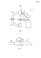
на Фиг. 1 показан вид сбоку безмаркерной системы отслеживания согласно одному варианту осуществления настоящего изобретения;in FIG. 1 is a side view of a markerless tracking system according to one embodiment of the present invention;
на Фиг. 2 показан вид в разрезе соединителя для крепления инструмента к кабелю безмаркерной системы отслеживания согласно одному варианту осуществления настоящего изобретения;in FIG. 2 is a sectional view of a connector for attaching a tool to a cable of a markerless tracking system according to one embodiment of the present invention;
на Фиг. 3 показан вид в разрезе кабеля безмаркерной системы отслеживания согласно одному варианту осуществления настоящего изобретения;in FIG. 3 is a cross-sectional view of a cable of a markerless tracking system according to one embodiment of the present invention;
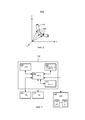
на Фиг. 4 показан вид в разрезе оптического волокна, где представлены четыре оптические сердцевины согласно одному варианту осуществления настоящего изобретения;in FIG. 4 is a cross-sectional view of an optical fiber showing four optical cores according to one embodiment of the present invention;
на Фиг. 5A-5C показаны графики спектрального отклика для волоконной брэгговской решетки согласно одному варианту осуществления настоящего изобретения;in FIG. 5A-5C show spectral response plots for a fiber Bragg grating according to one embodiment of the present invention;
на Фиг. 6 показан изометрический вид секции кабеля, где представлены датчики для измерения кривизны согласно одному варианту осуществления настоящего изобретения;in FIG. 6 is an isometric view of a cable section showing sensors for measuring curvature according to one embodiment of the present invention;
на Фиг. 7 показана блок-схема безмаркерной системы отслеживания согласно одному варианту осуществления настоящего изобретения;in FIG. 7 is a block diagram of a markerless tracking system according to one embodiment of the present invention;
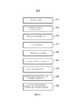
на Фиг. 8 показана блок-схема алгоритма способа отслеживания инструмента в пространстве изображений при отсутствии маркеров согласно одному варианту осуществления настоящего изобретения; иin FIG. 8 is a flowchart of a method for tracking a tool in an image space in the absence of markers according to one embodiment of the present invention; and
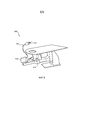
на Фиг. 9 показан вид с боку безмаркерной системы отслеживания согласно альтернативному варианту осуществления настоящего изобретения.in FIG. 9 is a side view of a markerless tracking system according to an alternative embodiment of the present invention.
В настоящем изобретении предложены способ и система для безмаркерного отслеживания инструмента в процессе интервенционной процедуры, и для отображения пространства изображений, соответствующего выбранному инструменту, при этом в пространстве изображений показана функциональная часть выбранного инструмента.The present invention provides a method and system for markerless tracking of an instrument during an interventional procedure, and for displaying an image space corresponding to a selected tool, wherein the functional part of the selected tool is shown in the image space.
Согласно одному варианту осуществления настоящего изобретения система 10 отслеживания инструмента содержит систему 100 визуализации, используемую для получения и отображения пространства изображений, представляющего анатомические структуры перед проведением интервенционной процедуры. Система 100 визуализации может представлять собой CT-визуализирующую систему с плоским детектором на C-образном штативе, показанную на Фиг. 1. По альтернативному варианту система визуализации может представлять собой визуализирующую систему MRI, CY, рентгеновского, ультразвукового или любого другого типа, пригодную для получения изображений анатомических структур с целью использования при направлении инструмента в процессе проведения интервенционной процедуры. Согласно одному варианту осуществления система 100 визуализации представляет собой визуализирующую систему, способную обеспечить трехмерный объем изображений.According to one embodiment of the present invention, the
Система 10 отслеживания инструмента также содержит инструмент 200 для использования в интервенционной процедуре. Инструмент может представлять собой любой инструмент, используемый при хирургическом вмешательстве, в том числе, но не только: механический скальпель (ланцет), лазерный скальпель, эндоскоп, микроскопические визуализирующие зонды, хирургические сшиватели, ретрактор, устройство для прижигания (электрическое или оптическое), катетер, медицинское долото, зажим, троакар, ножницы и т.п. Врач манипулирует инструментом 200 для выполнения интервенционной процедуры. Во многих интервенционных процедурах врач использует более одного инструмента. Следовательно, согласно одному варианту осуществления система отслеживания инструмента содержит более чем один инструмент.
Инструмент 200 (или один из инструментов) соединен с точкой 101 соединения на системе 100 визуализации с помощью кабеля 300. Точка 101 соединения представляет собой точку, которая может быть зафиксирована в системе координат пространства изображений системы 100 визуализации. Согласно одному варианту осуществления точка соединения представляет собой оптический соединитель 110. В представленном варианте осуществления оптический соединитель 110 зафиксирован на корпусе C-образной рамы CT-визуализирующей системы.The tool 200 (or one of the tools) is connected to the
Инструмент 200 соединен с кабелем 300 с помощью соединителя 310. Согласно одному варианту осуществления в соединителе 310 используется захватное усилие для прочного удерживания инструмента на месте. Соединитель 310 содержит цилиндр 311, жестко соединенный с кабелем 300 путем обжатия, с помощью клеящего вещества или любого иного пригодного способа крепления. Цилиндр может быть выполнен из пластика или любого другого подходящего рентгенопрозрачного конструкционного материала. Цилиндр 311 имеет наружную резьбу, входящую в зацепление с внутренней резьбой на хомуте 312. Хомут также может быть выполнен из пластика или любого другого подходящего рентгенопрозрачного конструкционного материала. Выполненная на конус гибкая оболочка 313 проходит в хомут противоположно кабелю 300 и крепится к цилиндру 311 с помощью клеящего вещества, путем обжатия или любого другого пригодного способа крепления. Гибкая оболочка может быть выполнена из резины или любого другого рентгенопрозрачного гибкого материала, пригодного для деформирования и зажатия инструмента. Инструмент 200 помещен в открытую выполненную на конус гибкую оболочку 313 и может упираться во фланец цилиндра 311 для точного позиционирования инструмента 200 относительно кабеля 300. Хомут 312 совершает поворот вокруг цилиндра 311, что продвигает хомут 312 вдоль его оси в направлении от кабеля 300, обжимая выполненную на конус гибкую оболочку 313, чтобы надежно удерживать инструмент 200 на месте.The
Соединитель 310 позволяет врачу прикрепить к кабелю 300 любой из множества инструментов 200. Кроме того, соединитель 310 позволяет врачу заменять инструменты в процессе интервенционной процедуры, как будет описано ниже.
Согласно альтернативным вариантам осуществления инструмент 200 может быть присоединен к кабелю 300 с помощью клеящего вещества, магнитного соединения, резьбового зацепления инструмента непосредственно с кабелем 300 или резьбовым звеном, прикрепленным к кабелю, либо любого другого пригодного способа соединения.According to alternative embodiments, the
Кабель 300 содержит оптоволоконные сердцевины 324 (Фиг. 3), которые совместно с оптической консолью 400 (Фиг. 1) образуют систему 320 измерения формы, предоставляющую информацию о деформациях. Данная информация может использоваться для определения точного местонахождения инструмента 200 и представления местонахождения инструмента на изображении, получаемом от системы 100 визуализации.
В кабеле 300 вдоль оси 325 кабеля проходят, по меньшей мере, одно, но предпочтительно четыре оптических волокна 324, как показано на Фиг. 3. Предпочтительно одна сердцевина волокна расположена по оси, а другие расположены по спирали вокруг осевой сердцевины волокна. Следует отметить, что эти четыре сердцевины могут содержаться в единственном волокне (тем самым имея общую оболочку) либо в отдельных волокнах, механически соединенных между собой (например, склеенных). Согласно одному варианту осуществления оптические волокна 324 расположены симметрично вокруг оси 325 кабеля. В оптоволоконных сердцевинах или оболочках создано множество оптических рассеивателей во множестве местоположений вдоль длины кабеля 300 (единственная волоконная брэгговская решетка показана на Фиг. 4).At least one but preferably four
Волоконная брэгговская решетка представляет собой сегмент оптического волокна, отражающий световое излучение с определенными длинами волн и пропускающий световое излучение со всеми остальными длинами волн. Это достигается путем периодического изменения показателя преломления в сердцевине волокна, что создает диэлектрическое зеркало, избирательное по длине волны. Волоконная брэгговская решетка, таким образом, может использоваться в качестве встроенного оптического фильтра, предназначенного для блокирования определенных длин волн, или в качестве отражателя, избирательного по длине волны.A fiber Bragg grating is an optical fiber segment that reflects light radiation with specific wavelengths and transmits light radiation with all other wavelengths. This is achieved by periodically changing the refractive index in the fiber core, which creates a dielectric mirror that is selective in wavelength. The fiber Bragg grating can thus be used as an integrated optical filter designed to block specific wavelengths, or as a reflector selective in wavelength.
Как показано на Фиг. 4, сердцевина оптического волокна 324 имеет показатель преломления вдоль большей части своей длины, равный n2. Однако показатель преломления периодически изменяется, принимая значение n3 на расстоянии λB/2neff (где neff - эффективный показатель преломления оптической моды). На Фиг. 5A-5C показан спектральный отклик широкополосного светового сигнала, поступившего на брэгговскую решетку. Как показано на Фиг. 5A, световой сигнал широкого спектра является входным для оптического волокна 324. Световое излучение расщепляется на световое излучение, длина волны которого не равна λB, пропускаемое через брэгговскую решетку (показано на Фиг. 5B), и световое излучение с длиной волны λB, которое отражается брэгговской решеткой (показано на Фиг. 5C).As shown in FIG. 4, the core of the
Волоконная брэгговская решетка создает френелевское отражение на каждой границе раздела, где изменяется показатель преломления. Для некоторых длин волн отраженное световое излучение различных периодов совпадает по фазе, так что для отражения имеет место усиливающая интерференция, а значит, для пропускания - ослабляющая интерференция.The fiber Bragg grating creates a Fresnel reflection at each interface, where the refractive index changes. For some wavelengths, the reflected light of different periods coincides in phase, so that amplifying interference takes place for reflection and, therefore, attenuation interference for transmission.
Брэгговская длина волны чувствительна к деформации и температуре. Это означает, что брэгговские решетки могут быть использованы в качестве сенсорных элементов в волоконно-оптических датчиках. В FBG-датчике измеряемая величина вызывает сдвиг в брэгговской длине волны λB. Относительный сдвиг в брэгговской длине волны, δλβ/λβ, вследствие приложенной деформации (ε) и изменения температуры (δΤ) приближенно выражается следующим соотношением:The Bragg wavelength is sensitive to deformation and temperature. This means that Bragg gratings can be used as sensor elements in fiber optic sensors. In the FBG sensor, the measured value causes a shift in the Bragg wavelength λB. The relative shift in the Bragg wavelength, δλβ / λβ, due to the applied deformation (ε) and temperature change (δΤ) is approximately expressed by the following relation:
δλB/λB=Csε+CTδΤ. (1)δλ B / λ B = C s ε + C T δΤ. (one)
Коэффициент Cs называют коэффициентом деформации и его величина обычно составляет около 0,8×10⁻⁶/µε (или в абсолютных величинах около 1 пм/µε). Коэффициент CT описывает чувствительность датчика к температуре; он получен из коэффициента термического расширения с учетом термооптического эффекта. Его значение составляет около 7×10⁻⁶/K (или в абсолютных величинах 13 пм/K).The coefficient Cs is called the strain coefficient and its value is usually about 0.8 × 10⁻⁶ / µε (or in absolute values about 1 pm / µε). CT ratio describes the sensitivity of the sensor to temperature; it is obtained from the coefficient of thermal expansion taking into account the thermo-optical effect. Its value is about 7 × 10⁻⁶ / K (or in absolute terms 13 pm / K).
Множество оптических рассеивателей 330 (например, волоконных брэгговских решеток или рэлеевских рассеивателей) могут быть распределены по длине оптического волокна в сердцевине или оболочке для образования датчиков или измерителей для измерения деформации. Введение, по меньшей мере, четырех оптоволоконных сердцевин, имеющих различные датчики (измерители) по длине волокна, встроенного в конструкцию, позволяет точно определить трехмерную форму конструкции. Как показано на Фиг. 6, рассеиватели 330 расположены в каждой из множества точек вдоль длины кабеля 300. Локальную кривизну кабеля 300 можно определить из результатов измерений разложенной по длине деформации и кривизны, полученных на кабеле 300. Общая трехмерная форма кабеля 300 определяется из множества результатов измерений деформации и кривизны.Many optical diffusers 330 (for example, fiber Bragg gratings or Rayleigh diffusers) can be distributed along the length of the optical fiber in the core or cladding to form sensors or meters for measuring strain. The introduction of at least four fiber optic cores having various sensors (meters) along the length of the fiber embedded in the structure allows you to accurately determine the three-dimensional shape of the structure. As shown in FIG. 6, the
Согласно одному варианту осуществления может использоваться множество кабелей для одновременного отслеживания множества инструментов в координатах объема изображений, полученных системой 100 визуализации.According to one embodiment, multiple cables may be used to simultaneously track multiple tools in the volume coordinates of images obtained by the
Как опять же показано на Фиг. 1, оптическая консоль 400 соединена с оптоволоконными сердцевинами 324 кабеля 300 в точке 101 соединения. В представленном варианте осуществления оптическая консоль установлена в пределах корпуса C-образной рамы системы 100 визуализации. Оптическая консоль 400 подает световое излучение в оптические волокна и/или оптоволоконные сердцевины и принимает световое излучение из них. В случае использования волоконных брэгговских решеток оптическая консоль 400 может определять брэгговскую длину волны λB для различных положений каждой волоконной брэгговской решетки 322.As again shown in FIG. 1, the
Согласно одному варианту осуществления на C-образной раме системы 100 визуализации расположено крепежное средство 150 для закрепления свободного конца кабеля 300 в ходе ротационного сканирования. Крепежное средство может представлять собой любое механическое соединительное устройство, пригодное для закрепления кабеля 300.According to one embodiment, fastening means 150 are arranged on the C-frame of the
На Фиг. 7 показана блок-схема системы 10 для направления инструмента, представленной на Фиг. 1. Процессорный блок 500 содержит процессор 510, функционально связанный с запоминающим устройством 520. Согласно одному варианту осуществления они соединены посредством шины 530. Процессор 510 может представлять собой любое устройство, способное выполнять команды программ, например один или несколько микропроцессоров. Запоминающее устройство может представлять собой любое энергозависимое или энергонезависимое запоминающее устройство, например сменный диск, накопитель на жестких дисках, компакт-диск, оперативное запоминающее устройство (RAM), постоянное запоминающее устройство (ROM) и т.п.In FIG. 7 is a block diagram of a
С процессором 510 также функционально связан дисплей 540. Дисплей может представлять собой любой монитор, экран и т.п., пригодный для создания графического интерфейса пользователя (GUI), способного представлять медицинские изображения.A
Блок 120 визуализации, такой как C-образная рама 102 (на Фиг. 1), функционально связан с процессором 510. Блок визуализации обеспечивает поступление данных изображения в процессор 510 для обработки с целью создания объема изображений анатомических объектов. Объем изображений далее выводится на дисплей 540. Процессорный блок 500 и блок 120 визуализации совместно образуют систему 100 визуализации.An
Блок 550 определения формы обеспечивает подачу данных деформации и кривизны от кабеля 300 в процессор 510. Блок определения формы содержит оптический датчик формы (в том числе оптоволоконные сердцевины 324, расположенные в кабеле 300 вдоль продольной оси 325). Блок 550 определения формы дополнительно содержит оптическую консоль 400, которая опрашивает оптоволоконные сердцевины, посылая широкополосный световой сигнал вдоль каждой оптоволоконной сердцевины и измеряя длины волн отраженных сигналов для определения разложенных по длине деформации и кривизны в каждой оптоволоконной сердцевине. По альтернативному варианту спектр отражения можно получить с использованием узкополосного светового источника с изменением длин волн во времени. Локализованная кривизна используется для определения формы кабеля 300 в пространстве изображений.The
Оптическая консоль 400 может иметь процессор (не показан), отдельный от процессора 510 в процессорном блоке 500. Кроме того, оптический модуль 400 может выполнять некоторые или все расчеты по сдвигу длины волны, деформации и кривизне, а также передачу данных по результатам измерений длины волны, вычислений сдвига, вычислений деформации или кривизны в процессор 510. Процессор 510 обрабатывает данные изображений для образования пространства изображений, выводимого на дисплей 540. Данные, полученные из блока 550 определения формы, подвергаются необходимой обработке для расчета величин кривизны по длине кабеля 300. Эти данные в отношении формы используются процессором 510 совместно с известной реперной точкой 101 на зафиксированном конце кабеля 300 (Фиг. 1) для определения местоположения и ориентации кабеля 300 в соединении 310, а значит, местоположения и ориентации инструмента 200 в пространстве изображений.The
Блок 560 идентификации инструмента (IIU) функционально связан с процессором 510 в процессорном блоке 500. Блок 560 IIU содержит средство для идентификации одного из множества инструментов 200, используемых врачом в процессе интервенционной процедуры. Средство идентификации может содержать приемник для радиочастотной идентификации (RFID), при этом каждый инструмент 200 или его упаковка имеет прикрепленный к ним RFID-передатчик. По альтернативному варианту средство идентификации может представлять собой устройство считывания штрихового кода, при этом каждый инструмент 200 или его упаковка имеет отпечатанный на них штриховой код. Согласно другому варианту осуществления в каждый инструмент 200 может быть встроен код сопротивления или микросхема, либо прикреплены к нему. Согласно еще одному варианту осуществления средство идентификации может представлять собой клавиатуру или клавишную панель, при этом врач вручную вводит идентификационный индикатор, такой как код, или осуществляет выбор из меню и т.д. Средство идентификации может быть выполнено заодно с соединителем 310, так что идентификационная информация передается по кабелю 300. По альтернативному варианту средство идентификации может быть расположено в другом местоположении, так что процессорный блок с инструментом 200 переносятся к средству идентификации для проведения идентификации.Tool identification unit (IIU) 560 is operatively coupled to a
Обратимся теперь к Фиг. 8, на которой показана блок-схема алгоритма для способа динамического отслеживания инструмента в пространстве изображений. Пациент располагается на системе 100 визуализации (этап 810). Размещение пациента выполняется согласно процедурам, известным в данной области техники.Turning now to FIG. 8, which shows a flowchart for a method for dynamically tracking an instrument in an image space. The patient is located on the imaging system 100 (step 810). Patient placement is performed according to procedures known in the art.
Согласно одному варианту осуществления пациент располагается на XperCT-системе визуализации в пределах корпуса C-образной рамы, как показано на Фиг. 1.According to one embodiment, the patient is located on the XperCT imaging system within the body of the C-frame, as shown in FIG. one.
Пациенту проводится трехмерное ротационное XperCT-сканирование (этап 820). Сканирование выполняется согласно процедурам, известным в данной области техники. Следует понимать, что возможны альтернативные варианты осуществления с использованием других видов визуализации, отличных от трехмерного ротационного XperCT-сканирования. Кроме того, сканирование может выполняться до хирургического вмешательства, в процессе хирургического вмешательства или то и другое.The patient undergoes a three-dimensional rotational XperCT scan (block 820). Scanning is performed according to procedures known in the art. It should be understood that alternative embodiments are possible using other types of imaging other than three-dimensional rotational XperCT scanning. In addition, scanning can be performed prior to surgery, during surgery, or both.
Процессор 510 конструирует объем изображений по данным сканирования (этап 830). Конструирование объема изображений выполняется согласно процедурам, известным в данной области техники, для показа анатомических структур.A
Врач подсоединяет кабель 300 к блоку визуализации системы 100 визуализации в точке 101 соединения (этап 840). Точка 101 соединения представляет собой местоположение, которое может быть совмещено с объемом изображений. Это означает, что местоположение точки соединения относительно объема изображений известно. В точке 101 соединения предусмотрен оптический соединитель 110. Согласно одному варианту осуществления точка 101 соединения расположена на корпусе C-образной рамы XperCT-системы визуализации. Согласно другому варианту осуществления точка соединения может располагаться на источнике или детекторе для любой системы визуализации.The doctor connects the
Врач подсоединяет кабель 300 к системе 100 визуализации (этап 850). Кабель установлен в оптическом соединителе 110, который соединен оптическими волокнами с оптической консолью 400. Согласно одному варианту осуществления кабель 300 подсоединяется после того как сканирование выполнено. Согласно другому варианту осуществления кабель 300 подсоединяется до проведения сканирования и крепится к системе 100 визуализации на своем дистальном конце с использованием крепежного средства 150.The physician connects the
Блок 560 идентификации инструмента идентифицирует выбранный инструмент 200 (этап 860). Как говорилось выше, блок 560 идентификации инструмента может представлять собой RFID-приемник, устройство считывания штрихового кода, клавиатуру или клавишную панель, электрический датчик или любое другое средство, пригодное для обеспечения кода или сигнала для указания инструмента, выбранного из множества инструментов 200. RFID-передатчик, штриховой код и т.п. могут обеспечиваться на выбранном инструменте 200 или на его упаковке. В примере с RFID врач берет инструмент 200 или упаковку с RFID-передатчиком и располагает вблизи RFID-приемника блока 560 идентификации инструмента. RFID-приемник блока 560 идентификации инструмента принимает RFID-сигнал и передает RFID-код в процессор 510. По альтернативному варианту идентификационный код может принимать процессор, отдельный от процессора 510 визуализации. В альтернативном варианте осуществления врач вводит код идентификации инструмента 200, используя клавиатуру или клавишную панель и т.п.
Процессор 510 определяет форму кабеля 300 (этап 870). Используя известные схемы расчета, известную точку 101 соединения и данные по кривизне, полученные от каждой тройки датчиков 330 вдоль длины кабеля 300, процессор 510 визуализации рассчитывает полную трехмерную форму кабеля и совмещает ее с объемом изображений. Согласно альтернативным вариантам осуществления форму кабеля 300 определяет процессор, отдельный от процессора 510 визуализации. Кроме того, согласно различным вариантам осуществления расчеты деформаций и расчеты кривизны могут выполняться процессором 510 визуализации, другим процессором или комбинацией таковых. По альтернативному варианту процессор может выполнять расчет полной трехмерной формы участка клинически пригодного кабеля; положение данного участка кабеля может быть определено относительно системы визуализации или иной структуры с помощью одного или более маркеров, расположенных на кабеле и отслеживаемых с помощью известных способов, не включающих в себя оптические волокна или оптоволоконные сердцевины, описанные в данном изобретении (например, EM-отслеживание).The
Процессор 510 определяет местоположение и ориентацию функциональной части выбранного инструмента 200 (этап 880). Когда трехмерная форма кабеля, точка 101 соединения и идентификация выбранного инструмента 200 известны, процессор 510 визуализации определяет местоположение функциональной части выбранного инструмента 200 и ориентацию выбранного инструмента 200 в пространстве изображений. Определение осуществляется с использованием запрограммированной формы и размера для выбранного инструмента 200.The
Процессор 510 выводит на экран объем изображений пациента, соответствующий выбранному инструменту, показывая инструмент в объеме изображений (этап 890). Для различных инструментов 200 могут оказаться более целесообразными разные виды объема изображений. Например, для вмешательства, предполагающего введение иглы, более подходящим может стать объем изображений, в котором сегментированы и выделены критичные структуры, такие как кровеносные сосуды. В качестве другого примера, при вмешательстве, предполагающем удаление опухолевой ткани головного мозга с помощью скальпеля или аспирационного устройства, более подходящим может оказаться объем изображений, в котором сегментирована и выделена опухолевая ткань. Процессор 510 выводит на экран изображение, в соответствии с которым выбирается инструмент 200 и для которого он является наиболее рациональным. Процессор 510 показывает выбранный инструмент 200 на изображении.The
Выведенное на экран изображение может быть получено из предоперационного сканирования или сканирования, выполненного в процессе вмешательства. Например, предоперационное изображение может быть получено с использованием CT или MRI. Вслед за визуализирующим обследованием пациента перемещают на операционный стол, где получают XperCT-изображение (при ротационном сканировании с использованием C-образной рамы). XperCT-изображение регистрируется совместно с CT- и/или MRI-изображениями. Двумерные флуороскопические изображения могут быть получены в режиме реального времени и совмещены с предоперационными изображениями и XperCT-изображениями, например, для отслеживания (или уточнения) глубины проникновения скальпеля.The displayed image can be obtained from a preoperative scan or a scan performed during an intervention. For example, a preoperative image can be obtained using CT or MRI. Following the imaging examination, the patient is transferred to the operating table, where an XperCT image is obtained (during rotational scanning using a C-shaped frame). The XperCT image is recorded in conjunction with CT and / or MRI images. Two-dimensional fluoroscopic images can be obtained in real time and combined with preoperative images and XperCT images, for example, to track (or refine) the depth of penetration of a scalpel.
В другом примере сбор предоперационных изображений не выполняется. Пациента помещают на операционный стол, где получают XperCT-изображение до начала проведения операции (при ротационном сканировании с использованием C-образной рамы) и возможно в различные моменты времени в процессе операции. В качестве опции флуороскопические изображения могут быть получены в режиме реального времени и совмещены с XperCT-изображениями.In another example, the collection of preoperative images is not performed. The patient is placed on the operating table, where they receive an XperCT image before the operation (during rotational scanning using the C-shaped frame) and possibly at various points in time during the operation. As an option, fluoroscopic images can be obtained in real time and combined with XperCT images.
В другом примере сбор предоперационных изображений не выполняется. Пациента помещают на операционный стол с MRI-аппаратом открытого типа. Получают MRI-изображение до начала проведения операции и возможно в различные моменты времени в процессе операции.In another example, the collection of preoperative images is not performed. The patient is placed on an operating table with an open-type MRI device. An MRI image is obtained prior to the operation and possibly at various points in time during the operation.
В каждой из вышеописанных процедур функциональная часть инструмента 200 может совмещаться с любым из полученных изображений, поскольку кабель 300 зафиксирован в местоположении, которое определено относительно изображений (занимая фиксированное положение на визуализирующем оборудовании), при этом трехмерную форму кабеля 300 можно рассчитать, зная местонахождения инструмента 200. Выбранный инструмент 200 идентифицирован, так что форму и размер можно извлечь из запоминающего устройства и использовать для определения точного местонахождения функциональной части инструмента. Помимо этого, выбранный инструмент 200 может быть заменен в ходе операции. Например, врач может заменить скальпель на сшиватель. Поскольку новый выбранный инструмент 200 идентифицирован, как описано выше, местонахождение функциональной части нового инструмента 200 можно определить относительно пространства изображений и можно представить соответствующее изображение, показывающее новый выбранный инструмент 200.In each of the above procedures, the functional part of the
Согласно альтернативному варианту осуществления, на кабеле 300 или на выбранном инструменте 200 расположен, по меньшей мере, один рентгеноконтрастный маркер. Рентгеноконтрастный маркер зрительно доступен при проведении двумерной флуороскопии. Когда в процессе хирургического вмешательства используется 2D- флуороскопия, положение маркеров в плоскости, перпендикулярной оси «рентгеновский детектор-эмиттер», может быть определено в режиме реального времени. Определение может выполняться путем цифрового анализа флуороскопических изображений с использованием алгоритма распознавания паттернов изображений, хорошо известных в научных кругах. Положения маркеров могут использоваться в качестве референсных точек для повышения точности, с которой рассчитаны 3D-форма кабеля 300 и местоположение инструмента 200.According to an alternative embodiment, at least one radiopaque marker is located on the
Согласно другому альтернативному варианту осуществления на кабеле 300 или на выбранном инструменте 200 расположен, по меньшей мере, один электромагнитный (EM) или оптический маркер. Положения маркеров, определенные EM- или оптическим датчиками, используются в качестве референсных точек для повышения точности, с которой рассчитана 3D-форма кабеля 300 и/или инструмента 200.According to another alternative embodiment, at least one electromagnetic (EM) or optical marker is located on the
На Фиг. 9 кабель 300 для измерения формы жестко крепится к комбинированной системе 900 рентгеновской маммографии молочных желез/взятия биопсии. Кабель соединен либо с источником 910 рентгеновского излучения, либо детектором 920, либо системой для взятия биопсии, либо любой другой жесткой переходной точкой.In FIG. 9, a
Системы маммографии молочных желез способны получать информацию о глубинном расположении опухолевых узлов путем выполнения визуализации с томосинтезом, которая включает в себя перемещение камеры и детектора вокруг объекта (в данном случае молочной железы). На основе изображений, созданных с использованием данной процедуры, получают информацию о глубинном расположении опухоли, которая далее используется для направленной или автоматизированной биопсии молочных желез.Mammography systems for mammary glands are able to obtain information about the deep location of tumor nodes by performing imaging with tomosynthesis, which includes moving the camera and detector around an object (in this case, the mammary gland). Based on the images created using this procedure, information is obtained on the deep location of the tumor, which is then used for targeted or automated breast biopsy.
Используя кабель 300 для измерения формы, традиционную безмаркерную биопсийную иглу отслеживают и размещают с превосходной точностью на основе ранее полученных изображений, созданных с использованием томосинтеза. Поскольку кабель 300 механически соединен с комбинированной системой 900 визуализации/взятия биопсии, положение соединителя 310 инструмента, а значит, и биопсийной иглы, рассчитанное с применением алгоритма определения формы, автоматически совмещается с системой координат рентгеновских изображений, полученных с использованием томосинтеза.Using
Использование оптической системы измерения формы в данном конкретном случае практического применения имеет существенное преимущество в том, что она не чувствительна к EM-искажениям, возникающим при EM-отслеживании. EM-искажения возникают благодаря металлу, присутствующему повсеместно в современных системах рентгеновской маммографии/взятия биопсии.The use of an optical system for measuring shape in this particular case of practical application has a significant advantage in that it is not sensitive to EM distortions arising from EM tracking. EM distortion occurs due to the metal that is ubiquitous in modern X-ray mammography / biopsy systems.
Предшествующее описание и прилагаемые чертежи направлены на иллюстрацию, но не ограничение изобретения. Объем изобретения в полной мере охватывает эквивалентные варианты и конфигурации по нижеследующей формуле изобретения.The foregoing description and the annexed drawings are intended to illustrate, but not limit the invention. The scope of the invention fully covers equivalent options and configurations in the following claims.
Claims (24)
по меньшей мере один инструмент;
систему для получения анатомических изображений, относящихся к направлению инструмента;
кабель, соединенный с системой визуализации на зафиксированном конце в известном местоположении относительно визуализирующего устройства и соединенный с инструментом на дистальном конце, при этом кабель содержит оптические датчики формы;
оптическую консоль, выполненную с возможностью опроса оптических датчиков формы; и
процессор, выполненный с возможностью расчета локальной кривизны в различных положениях вдоль кабеля, определения трехмерной формы кабеля, используя определенные величины локальной кривизны, и определения местонахождения и ориентации инструмента относительно изображений, используя определенную форму кабеля и местонахождение зафиксированного конца кабеля.1. A system for tracking the functional part of the tool during the intervention procedure and display dynamic visualization corresponding to the functional part of the tool, containing:
at least one instrument;
system for obtaining anatomical images related to the direction of the instrument;
a cable connected to the imaging system at the fixed end at a known location relative to the imaging device and connected to the instrument at the distal end, the cable comprising optical shape sensors;
an optical console configured to interrogate optical shape sensors; and
a processor configured to calculate local curvature at various positions along the cable, determine the three-dimensional shape of the cable using specific values of local curvature, and determine the location and orientation of the tool relative to the images using the specific shape of the cable and the location of the fixed end of the cable.
принимают данные изображения из визуализирующего устройства;
строят объем изображения;
определяют трехмерную форму гибкого кабеля, имеющего один конец, соединенный с визуализирующим устройством, зафиксированный в известном местоположении относительно визуализирующего устройства, и имеющего соединитель для инструмента, расположенный на противоположном конце;
определяют местонахождение функциональной части инструмента, используя известное местоположение зафиксированного конца кабеля, трехмерную форму кабеля и заданные размер и форму инструмента; и
отображают динамическое изображение, соответствующее инструменту, и показывают функциональную часть выбранного инструмента в объеме изображения.20. A method for tracking the functional part of a tool and displaying a dynamic visualization corresponding to the functional part of a tool, comprising the steps of:
receive image data from the imaging device;
Build the volume of the image;
determining a three-dimensional shape of a flexible cable having one end connected to the imaging device, fixed at a known location relative to the imaging device, and having a tool connector located at the opposite end;
determining the location of the functional part of the tool using the known location of the fixed end of the cable, the three-dimensional shape of the cable and the specified size and shape of the tool; and
display a dynamic image corresponding to the tool, and show the functional part of the selected tool in the image volume.
принимают идентифицирующую информацию о выбранном инструменте, прикрепленном к соединителю для инструмента, выбранном из множества инструментов.22. The method according to p. 20, in which the tool is selected from a variety of tools, the method further comprising the steps of:
receiving identification information about a selected tool attached to a tool connector selected from a plurality of tools.
снимают инструмент;
прикрепляют к кабелю новый инструмент; и
принимают идентификацию нового инструмента.23. The method according to p. 22, further comprising stages in which:
remove the tool;
attach a new tool to the cable; and
accept the identification of the new tool.
Applications Claiming Priority (3)
| Application Number | Priority Date | Filing Date | Title |
|---|---|---|---|
| US39113710P | 2010-10-08 | 2010-10-08 | |
| US61/391,137 | 2010-10-08 | ||
| PCT/IB2011/054400 WO2012046202A1 (en) | 2010-10-08 | 2011-10-06 | Flexible tether with integrated sensors for dynamic instrument tracking |
Publications (2)
| Publication Number | Publication Date |
|---|---|
| RU2013120967A RU2013120967A (en) | 2014-11-20 |
| RU2597136C2 true RU2597136C2 (en) | 2016-09-10 |
Family
ID=44898092
Family Applications (1)
| Application Number | Title | Priority Date | Filing Date |
|---|---|---|---|
| RU2013120967/14A RU2597136C2 (en) | 2010-10-08 | 2011-10-06 | Flexible tether with integrated sensors for dynamic instrument tracking |
Country Status (6)
| Country | Link |
|---|---|
| US (1) | US9757034B2 (en) |
| EP (1) | EP2624780B1 (en) |
| JP (1) | JP5944395B2 (en) |
| CN (1) | CN103153223B (en) |
| RU (1) | RU2597136C2 (en) |
| WO (1) | WO2012046202A1 (en) |
Families Citing this family (50)
| Publication number | Priority date | Publication date | Assignee | Title |
|---|---|---|---|---|
| EP2023812B1 (en) | 2006-05-19 | 2016-01-27 | The Queen's Medical Center | Motion tracking system for real time adaptive imaging and spectroscopy |
| WO2013032933A2 (en) | 2011-08-26 | 2013-03-07 | Kinecticor, Inc. | Methods, systems, and devices for intra-scan motion correction |
| US9405085B2 (en) | 2011-10-26 | 2016-08-02 | Koninklijke Philips N.V. | Smart tool holder for an optical shape-sensing fiber |
| RU2014143669A (en) * | 2012-03-29 | 2016-05-27 | Конинклейке Филипс Н.В. | TROUBLESHOOTING USING FORM READING |
| EP2866667B1 (en) * | 2012-06-28 | 2019-10-16 | Koninklijke Philips N.V. | C-arm trajectory planning for optimal image acquisition in endoscopic surgery |
| US10952810B2 (en) | 2012-07-09 | 2021-03-23 | Koninklijke Philips N.V. | Method and system for adaptive image guided intervention |
| ITBO20120479A1 (en) * | 2012-09-12 | 2014-03-13 | Sintea Plustek S R L | SENSORIZED RETRACTOR DEVICE FOR FABRICS IN SURGERY |
| JP6246213B2 (en) * | 2012-10-01 | 2017-12-13 | コーニンクレッカ フィリップス エヌ ヴェKoninklijke Philips N.V. | Alignment system, method and computer program |
| US9717461B2 (en) | 2013-01-24 | 2017-08-01 | Kineticor, Inc. | Systems, devices, and methods for tracking and compensating for patient motion during a medical imaging scan |
| US10327708B2 (en) | 2013-01-24 | 2019-06-25 | Kineticor, Inc. | Systems, devices, and methods for tracking and compensating for patient motion during a medical imaging scan |
| US9305365B2 (en) | 2013-01-24 | 2016-04-05 | Kineticor, Inc. | Systems, devices, and methods for tracking moving targets |
| CN109008972A (en) | 2013-02-01 | 2018-12-18 | 凯内蒂科尔股份有限公司 | The motion tracking system of real-time adaptive motion compensation in biomedical imaging |
| EP3014214B1 (en) * | 2013-06-28 | 2021-08-11 | Koninklijke Philips N.V. | Optical shape sensing with a plurality of optical fibers |
| EP3055646B1 (en) * | 2013-10-02 | 2020-12-16 | Koninklijke Philips N.V. | Device tracking using longitudinal encoding |
| WO2015049612A2 (en) * | 2013-10-02 | 2015-04-09 | Koninklijke Philips N.V. | Hub design and methods for optical shape sensing registration |
| WO2015148391A1 (en) | 2014-03-24 | 2015-10-01 | Thomas Michael Ernst | Systems, methods, and devices for removing prospective motion correction from medical imaging scans |
| US9734589B2 (en) | 2014-07-23 | 2017-08-15 | Kineticor, Inc. | Systems, devices, and methods for tracking and compensating for patient motion during a medical imaging scan |
| US9754372B2 (en) * | 2014-08-15 | 2017-09-05 | Biosense Webster (Israel) Ltd. | Marking of fluoroscope field-of-view |
| JP6894836B2 (en) * | 2014-09-08 | 2021-06-30 | コーニンクレッカ フィリップス エヌ ヴェKoninklijke Philips N.V. | Optical shape detection for instrument tracking in orthopedics |
| JP6841757B2 (en) * | 2014-12-01 | 2021-03-10 | コーニンクレッカ フィリップス エヌ ヴェKoninklijke Philips N.V. | Alignment of optical shape sensing tools |
| GB2536650A (en) | 2015-03-24 | 2016-09-28 | Augmedics Ltd | Method and system for combining video-based and optic-based augmented reality in a near eye display |
| US11141222B2 (en) | 2015-06-12 | 2021-10-12 | Koninklijke Philips N.V. | Universal fiber-optical realshape insert |
| JP6790000B2 (en) * | 2015-06-30 | 2020-11-25 | コーニンクレッカ フィリップス エヌ ヴェKoninklijke Philips N.V. | Fiber Optic Real Shape Sensing for X-ray Fluoroscopic Surgery Navigation |
| US9943247B2 (en) | 2015-07-28 | 2018-04-17 | The University Of Hawai'i | Systems, devices, and methods for detecting false movements for motion correction during a medical imaging scan |
| JP6945293B2 (en) * | 2015-11-16 | 2021-10-06 | キヤノンメディカルシステムズ株式会社 | X-ray diagnostic equipment and medical diagnostic imaging system |
| WO2017091479A1 (en) | 2015-11-23 | 2017-06-01 | Kineticor, Inc. | Systems, devices, and methods for tracking and compensating for patient motion during a medical imaging scan |
| EP3397183B1 (en) * | 2015-12-29 | 2022-10-19 | Koninklijke Philips N.V. | Registration system for medical navigation and method of operation thereof |
| CN114652441A (en) | 2016-02-12 | 2022-06-24 | 直观外科手术操作公司 | System and method for pose estimation in image-guided surgery and calibration of fluoroscopic imaging system |
| US11160541B2 (en) | 2016-05-10 | 2021-11-02 | Koninklijke Philips N.V. | Biopsy container |
| JP6717713B2 (en) * | 2016-08-31 | 2020-07-01 | テルモ株式会社 | Medical device |
| WO2018096491A1 (en) | 2016-11-28 | 2018-05-31 | Koninklijke Philips N.V. | Shape sensing of multiple over-the-wire devices |
| WO2019118326A1 (en) * | 2017-12-11 | 2019-06-20 | Dragerwerk AG & Co. KGaA | Cable manager |
| CN108577977B (en) * | 2018-03-19 | 2020-10-30 | 山东大学 | Puncture needle and three-dimensional reconstruction method and system for puncture needle motion trail |
| EP3787543A4 (en) | 2018-05-02 | 2022-01-19 | Augmedics Ltd. | Registration of a fiducial marker for an augmented reality system |
| US11766296B2 (en) | 2018-11-26 | 2023-09-26 | Augmedics Ltd. | Tracking system for image-guided surgery |
| US11980506B2 (en) | 2019-07-29 | 2024-05-14 | Augmedics Ltd. | Fiducial marker |
| US11931112B2 (en) | 2019-08-12 | 2024-03-19 | Bard Access Systems, Inc. | Shape-sensing system and methods for medical devices |
| WO2021108688A1 (en) | 2019-11-25 | 2021-06-03 | Bard Access Systems, Inc. | Shape-sensing systems with filters and methods thereof |
| CN112826497A (en) | 2019-11-25 | 2021-05-25 | 巴德阿克塞斯系统股份有限公司 | Optical tip tracking system and method thereof |
| US11382712B2 (en) | 2019-12-22 | 2022-07-12 | Augmedics Ltd. | Mirroring in image guided surgery |
| US20210268229A1 (en) * | 2020-02-28 | 2021-09-02 | Bard Access Systems, Inc. | Catheter with Optic Shape Sensing Capabilities |
| CN215340440U (en) | 2020-02-28 | 2021-12-28 | 巴德阿克塞斯系统股份有限公司 | Electrical and optical connection system |
| US11931179B2 (en) | 2020-03-30 | 2024-03-19 | Bard Access Systems, Inc. | Optical and electrical diagnostic systems and methods thereof |
| CN216319408U (en) | 2020-06-26 | 2022-04-19 | 巴德阿克塞斯系统股份有限公司 | Dislocation detection system |
| EP4171373A1 (en) | 2020-06-29 | 2023-05-03 | Bard Access Systems, Inc. | Automatic dimensional frame reference for fiber optic |
| CN113907705A (en) | 2020-07-10 | 2022-01-11 | 巴德阿克塞斯系统股份有限公司 | Continuous optical fiber function monitoring and self-diagnosis reporting system |
| CN114052658A (en) | 2020-08-03 | 2022-02-18 | 巴德阿克塞斯系统股份有限公司 | Bragg grating optical fiber fluctuation sensing and monitoring system |
| EP4229456A1 (en) | 2020-10-13 | 2023-08-23 | Bard Access Systems, Inc. | Disinfecting covers for functional connectors of medical devices and methods thereof |
| CN113349928B (en) * | 2021-05-20 | 2023-01-24 | 清华大学 | Augmented reality surgical navigation device for flexible instrument |
| US11896445B2 (en) | 2021-07-07 | 2024-02-13 | Augmedics Ltd. | Iliac pin and adapter |
Citations (6)
| Publication number | Priority date | Publication date | Assignee | Title |
|---|---|---|---|---|
| US4821727A (en) * | 1986-10-30 | 1989-04-18 | Elscint Ltd. | Mammographic biopsy needle holder system |
| WO2008053402A1 (en) * | 2006-11-03 | 2008-05-08 | Koninklijke Philips Electronics N.V. | Multiple rotation c-arm |
| US20100030063A1 (en) * | 2008-07-31 | 2010-02-04 | Medtronic, Inc. | System and method for tracking an instrument |
| US20100076455A1 (en) * | 2008-09-19 | 2010-03-25 | Rainer Birkenbach | Surgical instrument, in particular pointer instrument, comprising tip sensor |
| RU2391701C2 (en) * | 2003-07-22 | 2010-06-10 | Майкрософт Корпорейшн | Methods for detection of approximate location of device on basis of external signals |
| US20100249507A1 (en) * | 2009-03-26 | 2010-09-30 | Intuitive Surgical, Inc. | Method and system for providing visual guidance to an operator for steering a tip of an endoscopic device toward one or more landmarks in a patient |
Family Cites Families (28)
| Publication number | Priority date | Publication date | Assignee | Title |
|---|---|---|---|---|
| US5638819A (en) | 1995-08-29 | 1997-06-17 | Manwaring; Kim H. | Method and apparatus for guiding an instrument to a target |
| US6346940B1 (en) | 1997-02-27 | 2002-02-12 | Kabushiki Kaisha Toshiba | Virtualized endoscope system |
| US6522906B1 (en) | 1998-12-08 | 2003-02-18 | Intuitive Surgical, Inc. | Devices and methods for presenting and regulating auxiliary information on an image display of a telesurgical system to assist an operator in performing a surgical procedure |
| US6466815B1 (en) | 1999-03-30 | 2002-10-15 | Olympus Optical Co., Ltd. | Navigation apparatus and surgical operation image acquisition/display apparatus using the same |
| JP4116757B2 (en) * | 1999-08-24 | 2008-07-09 | オリンパス株式会社 | Electrical treatment system |
| US8221402B2 (en) * | 2000-01-19 | 2012-07-17 | Medtronic, Inc. | Method for guiding a medical device |
| DE10004764A1 (en) * | 2000-02-03 | 2001-08-09 | Philips Corp Intellectual Pty | Method for determining the position of a medical instrument |
| US6856827B2 (en) * | 2000-04-28 | 2005-02-15 | Ge Medical Systems Global Technology Company, Llc | Fluoroscopic tracking and visualization system |
| US6850794B2 (en) | 2000-09-23 | 2005-02-01 | The Trustees Of The Leland Stanford Junior University | Endoscopic targeting method and system |
| US6663559B2 (en) | 2001-12-14 | 2003-12-16 | Endactive, Inc. | Interface for a variable direction of view endoscope |
| WO2004039249A1 (en) | 2002-10-29 | 2004-05-13 | Olympus Corporation | Endoscope information processor and processing method |
| JP2004208922A (en) | 2002-12-27 | 2004-07-29 | Olympus Corp | Medical apparatus, medical manipulator and control process for medical apparatus |
| US7027699B2 (en) * | 2003-05-21 | 2006-04-11 | The Hong Kong Polytechnic University | Optical fiber and optical fiber sensors |
| US7232409B2 (en) | 2003-11-20 | 2007-06-19 | Karl Storz Development Corp. | Method and apparatus for displaying endoscopic images |
| US7772541B2 (en) * | 2004-07-16 | 2010-08-10 | Luna Innnovations Incorporated | Fiber optic position and/or shape sensing based on rayleigh scatter |
| US20060013523A1 (en) | 2004-07-16 | 2006-01-19 | Luna Innovations Incorporated | Fiber optic position and shape sensing device and method relating thereto |
| US7643862B2 (en) * | 2005-09-15 | 2010-01-05 | Biomet Manufacturing Corporation | Virtual mouse for use in surgical navigation |
| US7930065B2 (en) | 2005-12-30 | 2011-04-19 | Intuitive Surgical Operations, Inc. | Robotic surgery system including position sensors using fiber bragg gratings |
| JP5085996B2 (en) | 2006-10-25 | 2012-11-28 | テルモ株式会社 | Manipulator system |
| US20090036900A1 (en) | 2007-02-02 | 2009-02-05 | Hansen Medical, Inc. | Surgery methods using a robotic instrument system |
| WO2008115375A1 (en) * | 2007-03-16 | 2008-09-25 | Luna Innovations Incorporated | Fiber optic position and/or shape sensing based on rayleigh scatter |
| WO2009023801A1 (en) | 2007-08-14 | 2009-02-19 | Hansen Medical, Inc. | Robotic instrument systems and methods utilizing optical fiber sensor |
| US7720322B2 (en) | 2008-06-30 | 2010-05-18 | Intuitive Surgical, Inc. | Fiber optic shape sensor |
| JP5259340B2 (en) | 2008-10-28 | 2013-08-07 | オリンパスメディカルシステムズ株式会社 | Medical equipment |
| EP4012658A1 (en) | 2009-03-26 | 2022-06-15 | Intuitive Surgical Operations, Inc. | System for providing visual guidance for steering a tip of an endoscopic device towards one or more landmarks and assisting an operator in endoscopic navigation |
| US10004387B2 (en) * | 2009-03-26 | 2018-06-26 | Intuitive Surgical Operations, Inc. | Method and system for assisting an operator in endoscopic navigation |
| US8183520B2 (en) * | 2009-11-13 | 2012-05-22 | Intuitive Surgical Operations, Inc. | Optical fiber shape sensor calibration |
| US9285246B2 (en) * | 2010-02-12 | 2016-03-15 | Intuitive Surgical Operations, Inc. | Method and system for absolute three-dimensional measurements using a twist-insensitive shape sensor |
-
2011
- 2011-10-06 CN CN201180048443.2A patent/CN103153223B/en active Active
- 2011-10-06 JP JP2013532306A patent/JP5944395B2/en active Active
- 2011-10-06 RU RU2013120967/14A patent/RU2597136C2/en not_active IP Right Cessation
- 2011-10-06 EP EP11776549.5A patent/EP2624780B1/en active Active
- 2011-10-06 WO PCT/IB2011/054400 patent/WO2012046202A1/en active Application Filing
- 2011-10-06 US US13/877,343 patent/US9757034B2/en active Active
Patent Citations (6)
| Publication number | Priority date | Publication date | Assignee | Title |
|---|---|---|---|---|
| US4821727A (en) * | 1986-10-30 | 1989-04-18 | Elscint Ltd. | Mammographic biopsy needle holder system |
| RU2391701C2 (en) * | 2003-07-22 | 2010-06-10 | Майкрософт Корпорейшн | Methods for detection of approximate location of device on basis of external signals |
| WO2008053402A1 (en) * | 2006-11-03 | 2008-05-08 | Koninklijke Philips Electronics N.V. | Multiple rotation c-arm |
| US20100030063A1 (en) * | 2008-07-31 | 2010-02-04 | Medtronic, Inc. | System and method for tracking an instrument |
| US20100076455A1 (en) * | 2008-09-19 | 2010-03-25 | Rainer Birkenbach | Surgical instrument, in particular pointer instrument, comprising tip sensor |
| US20100249507A1 (en) * | 2009-03-26 | 2010-09-30 | Intuitive Surgical, Inc. | Method and system for providing visual guidance to an operator for steering a tip of an endoscopic device toward one or more landmarks in a patient |
Also Published As
| Publication number | Publication date |
|---|---|
| CN103153223A (en) | 2013-06-12 |
| RU2013120967A (en) | 2014-11-20 |
| US9757034B2 (en) | 2017-09-12 |
| CN103153223B (en) | 2016-09-14 |
| EP2624780A1 (en) | 2013-08-14 |
| JP5944395B2 (en) | 2016-07-05 |
| US20130188855A1 (en) | 2013-07-25 |
| JP2013542768A (en) | 2013-11-28 |
| EP2624780B1 (en) | 2024-02-14 |
| WO2012046202A1 (en) | 2012-04-12 |
Similar Documents
| Publication | Publication Date | Title |
|---|---|---|
| RU2597136C2 (en) | Flexible tether with integrated sensors for dynamic instrument tracking | |
| JP2013542768A5 (en) | ||
| EP2866642B1 (en) | Fiber optic sensor guided navigation for vascular visualization and monitoring | |
| US20190313976A1 (en) | Biopsy guidance by image-based x-ray system and photonic needle | |
| CN108601628B (en) | Navigation, tracking and guidance system for positioning a working instrument in a patient's body | |
| EP2249737B1 (en) | Biopsy guidance by electromagnetic tracking and photonic needle | |
| RU2535605C2 (en) | Recalibration of pre-recorded images during interventions using needle device | |
| EP2152153B1 (en) | Clean margin assessment tool | |
| RU2631193C2 (en) | Storage and search of information, characteristic for particular device for shape measurement | |
| CN105007815A (en) | Organ mapping system using an optical coherence tomography probe | |
| KR101588014B1 (en) | Methods for Preparing Complex Reality Three-Dimensional Images and Systems therefor | |
| CN107072743B (en) | Processing system arranged to cooperate with an optical shape sensing enabled interventional device | |
| CA2620196A1 (en) | System, method and devices for navigated flexible endoscopy | |
| CN107427202B (en) | Device, system and method for illuminating a structure of interest inside a human or animal body | |
| US10952810B2 (en) | Method and system for adaptive image guided intervention | |
| CN104244861A (en) | Photonic needle system with measurement integration times depending on needle displacement speed | |
| US6647285B2 (en) | Optical probe with light fluctuation protection | |
| US7013173B2 (en) | Optical probe with reference fiber | |
| Da Silva et al. | Optical probe with reference fiber |
Legal Events
| Date | Code | Title | Description |
|---|---|---|---|
| MM4A | The patent is invalid due to non-payment of fees |
Effective date: 20201007 |