JP6790000B2 - Fiber Optic Real Shape Sensing for X-ray Fluoroscopic Surgery Navigation - Google Patents
Fiber Optic Real Shape Sensing for X-ray Fluoroscopic Surgery Navigation Download PDFInfo
- Publication number
- JP6790000B2 JP6790000B2 JP2017567699A JP2017567699A JP6790000B2 JP 6790000 B2 JP6790000 B2 JP 6790000B2 JP 2017567699 A JP2017567699 A JP 2017567699A JP 2017567699 A JP2017567699 A JP 2017567699A JP 6790000 B2 JP6790000 B2 JP 6790000B2
- Authority
- JP
- Japan
- Prior art keywords
- surgical
- fors sensor
- fors
- sensor
- connector
- Prior art date
- Legal status (The legal status is an assumption and is not a legal conclusion. Google has not performed a legal analysis and makes no representation as to the accuracy of the status listed.)
- Active
Links
- 238000001356 surgical procedure Methods 0.000 title claims description 62
- 239000000835 fiber Substances 0.000 title description 15
- 238000002594 fluoroscopy Methods 0.000 claims description 45
- 238000002513 implantation Methods 0.000 claims description 27
- 230000004044 response Effects 0.000 claims description 7
- 238000003384 imaging method Methods 0.000 description 29
- 238000000034 method Methods 0.000 description 25
- 239000013307 optical fiber Substances 0.000 description 20
- 230000003287 optical effect Effects 0.000 description 15
- 210000003484 anatomy Anatomy 0.000 description 12
- 230000000399 orthopedic effect Effects 0.000 description 10
- 238000003780 insertion Methods 0.000 description 6
- 230000037431 insertion Effects 0.000 description 6
- 230000008569 process Effects 0.000 description 6
- 230000000644 propagated effect Effects 0.000 description 6
- 210000000988 bone and bone Anatomy 0.000 description 5
- 230000008901 benefit Effects 0.000 description 4
- 238000005520 cutting process Methods 0.000 description 3
- 238000010586 diagram Methods 0.000 description 3
- 239000011521 glass Substances 0.000 description 3
- 208000014674 injury Diseases 0.000 description 3
- 238000009434 installation Methods 0.000 description 3
- 238000005259 measurement Methods 0.000 description 3
- 230000001681 protective effect Effects 0.000 description 3
- 238000003860 storage Methods 0.000 description 3
- 230000008733 trauma Effects 0.000 description 3
- 238000012800 visualization Methods 0.000 description 3
- VYPSYNLAJGMNEJ-UHFFFAOYSA-N Silicium dioxide Chemical compound O=[Si]=O VYPSYNLAJGMNEJ-UHFFFAOYSA-N 0.000 description 2
- 230000008878 coupling Effects 0.000 description 2
- 238000010168 coupling process Methods 0.000 description 2
- 238000005859 coupling reaction Methods 0.000 description 2
- 230000006870 function Effects 0.000 description 2
- 230000004927 fusion Effects 0.000 description 2
- 238000010348 incorporation Methods 0.000 description 2
- 239000000463 material Substances 0.000 description 2
- 239000002184 metal Substances 0.000 description 2
- 238000012986 modification Methods 0.000 description 2
- 230000004048 modification Effects 0.000 description 2
- 239000004033 plastic Substances 0.000 description 2
- 238000010079 rubber tapping Methods 0.000 description 2
- 241000333074 Eucalyptus occidentalis Species 0.000 description 1
- 241000699670 Mus sp. Species 0.000 description 1
- 206010028980 Neoplasm Diseases 0.000 description 1
- 210000001015 abdomen Anatomy 0.000 description 1
- 210000003423 ankle Anatomy 0.000 description 1
- 230000006399 behavior Effects 0.000 description 1
- 230000009286 beneficial effect Effects 0.000 description 1
- 210000004204 blood vessel Anatomy 0.000 description 1
- 238000001514 detection method Methods 0.000 description 1
- 230000002526 effect on cardiovascular system Effects 0.000 description 1
- 238000011156 evaluation Methods 0.000 description 1
- 230000004438 eyesight Effects 0.000 description 1
- 239000012634 fragment Substances 0.000 description 1
- 238000002675 image-guided surgery Methods 0.000 description 1
- 230000006872 improvement Effects 0.000 description 1
- 230000010354 integration Effects 0.000 description 1
- 230000005865 ionizing radiation Effects 0.000 description 1
- 210000003127 knee Anatomy 0.000 description 1
- 238000004519 manufacturing process Methods 0.000 description 1
- 239000000203 mixture Substances 0.000 description 1
- 238000003032 molecular docking Methods 0.000 description 1
- 210000003205 muscle Anatomy 0.000 description 1
- 210000005036 nerve Anatomy 0.000 description 1
- HLXZNVUGXRDIFK-UHFFFAOYSA-N nickel titanium Chemical compound [Ti].[Ti].[Ti].[Ti].[Ti].[Ti].[Ti].[Ti].[Ti].[Ti].[Ti].[Ni].[Ni].[Ni].[Ni].[Ni].[Ni].[Ni].[Ni].[Ni].[Ni].[Ni].[Ni].[Ni].[Ni] HLXZNVUGXRDIFK-UHFFFAOYSA-N 0.000 description 1
- 229910001000 nickel titanium Inorganic materials 0.000 description 1
- 238000002168 optical frequency-domain reflectometry Methods 0.000 description 1
- 230000002093 peripheral effect Effects 0.000 description 1
- 239000005365 phosphate glass Substances 0.000 description 1
- 238000012545 processing Methods 0.000 description 1
- 238000002601 radiography Methods 0.000 description 1
- 230000008439 repair process Effects 0.000 description 1
- 230000003252 repetitive effect Effects 0.000 description 1
- 210000000513 rotator cuff Anatomy 0.000 description 1
- 239000000377 silicon dioxide Substances 0.000 description 1
- 230000000087 stabilizing effect Effects 0.000 description 1
- 210000000115 thoracic cavity Anatomy 0.000 description 1
- 230000000007 visual effect Effects 0.000 description 1
Images


Classifications
-
- A—HUMAN NECESSITIES
- A61—MEDICAL OR VETERINARY SCIENCE; HYGIENE
- A61B—DIAGNOSIS; SURGERY; IDENTIFICATION
- A61B6/00—Apparatus or devices for radiation diagnosis; Apparatus or devices for radiation diagnosis combined with radiation therapy equipment
- A61B6/54—Control of apparatus or devices for radiation diagnosis
- A61B6/547—Control of apparatus or devices for radiation diagnosis involving tracking of position of the device or parts of the device
-
- A—HUMAN NECESSITIES
- A61—MEDICAL OR VETERINARY SCIENCE; HYGIENE
- A61B—DIAGNOSIS; SURGERY; IDENTIFICATION
- A61B34/00—Computer-aided surgery; Manipulators or robots specially adapted for use in surgery
- A61B34/20—Surgical navigation systems; Devices for tracking or guiding surgical instruments, e.g. for frameless stereotaxis
-
- A—HUMAN NECESSITIES
- A61—MEDICAL OR VETERINARY SCIENCE; HYGIENE
- A61B—DIAGNOSIS; SURGERY; IDENTIFICATION
- A61B6/00—Apparatus or devices for radiation diagnosis; Apparatus or devices for radiation diagnosis combined with radiation therapy equipment
- A61B6/12—Arrangements for detecting or locating foreign bodies
-
- A—HUMAN NECESSITIES
- A61—MEDICAL OR VETERINARY SCIENCE; HYGIENE
- A61B—DIAGNOSIS; SURGERY; IDENTIFICATION
- A61B6/00—Apparatus or devices for radiation diagnosis; Apparatus or devices for radiation diagnosis combined with radiation therapy equipment
- A61B6/44—Constructional features of apparatus for radiation diagnosis
- A61B6/4429—Constructional features of apparatus for radiation diagnosis related to the mounting of source units and detector units
- A61B6/4435—Constructional features of apparatus for radiation diagnosis related to the mounting of source units and detector units the source unit and the detector unit being coupled by a rigid structure
- A61B6/4441—Constructional features of apparatus for radiation diagnosis related to the mounting of source units and detector units the source unit and the detector unit being coupled by a rigid structure the rigid structure being a C-arm or U-arm
-
- A—HUMAN NECESSITIES
- A61—MEDICAL OR VETERINARY SCIENCE; HYGIENE
- A61B—DIAGNOSIS; SURGERY; IDENTIFICATION
- A61B90/00—Instruments, implements or accessories specially adapted for surgery or diagnosis and not covered by any of the groups A61B1/00 - A61B50/00, e.g. for luxation treatment or for protecting wound edges
- A61B90/36—Image-producing devices or illumination devices not otherwise provided for
- A61B90/37—Surgical systems with images on a monitor during operation
-
- A—HUMAN NECESSITIES
- A61—MEDICAL OR VETERINARY SCIENCE; HYGIENE
- A61B—DIAGNOSIS; SURGERY; IDENTIFICATION
- A61B34/00—Computer-aided surgery; Manipulators or robots specially adapted for use in surgery
- A61B34/20—Surgical navigation systems; Devices for tracking or guiding surgical instruments, e.g. for frameless stereotaxis
- A61B2034/2046—Tracking techniques
- A61B2034/2061—Tracking techniques using shape-sensors, e.g. fiber shape sensors with Bragg gratings
-
- A—HUMAN NECESSITIES
- A61—MEDICAL OR VETERINARY SCIENCE; HYGIENE
- A61B—DIAGNOSIS; SURGERY; IDENTIFICATION
- A61B90/00—Instruments, implements or accessories specially adapted for surgery or diagnosis and not covered by any of the groups A61B1/00 - A61B50/00, e.g. for luxation treatment or for protecting wound edges
- A61B90/36—Image-producing devices or illumination devices not otherwise provided for
- A61B90/37—Surgical systems with images on a monitor during operation
- A61B2090/376—Surgical systems with images on a monitor during operation using X-rays, e.g. fluoroscopy
Landscapes
- Health & Medical Sciences (AREA)
- Life Sciences & Earth Sciences (AREA)
- Engineering & Computer Science (AREA)
- Medical Informatics (AREA)
- Surgery (AREA)
- Nuclear Medicine, Radiotherapy & Molecular Imaging (AREA)
- Veterinary Medicine (AREA)
- Public Health (AREA)
- Molecular Biology (AREA)
- General Health & Medical Sciences (AREA)
- Animal Behavior & Ethology (AREA)
- Biomedical Technology (AREA)
- Heart & Thoracic Surgery (AREA)
- Radiology & Medical Imaging (AREA)
- Pathology (AREA)
- Physics & Mathematics (AREA)
- Optics & Photonics (AREA)
- High Energy & Nuclear Physics (AREA)
- Biophysics (AREA)
- Robotics (AREA)
- Gynecology & Obstetrics (AREA)
- Oral & Maxillofacial Surgery (AREA)
- Apparatus For Radiation Diagnosis (AREA)
Description
本開示は、概して、任意の種類のX線透視ベースの外科手術処置(例えば、脊椎の外科手術、外傷の外科手術、腫瘍及び神経外科)中のX線透視イメージャ及び外科手術ツールの追跡に関する。本開示は、詳細には、任意の種類のX線透視ベースの外科手術処置中にX線透視イメージャ及び外科手術ツールを追跡するための光ファイバリアルシェイプ(「FORS」:Fiber−Optical RealShape)センサの新規的で発明的な組み込みに関する。 The present disclosure generally relates to tracking X-ray fluoroscopic imagers and surgical tools during any type of X-ray fluoroscopy-based surgical procedure (eg, spinal surgery, trauma surgery, tumor and neurosurgery). In this disclosure, in detail, a fiber optic real shape (“FORS”) sensor for tracking an X-ray fluoroscopic imager and surgical tool during any type of X-ray fluoroscopy-based surgical procedure. Concerning novel and innovative incorporation of.
当技術分野において知られる1つの整形外科器具は、ガイド、アンカーとしての、又は骨の断片を安定化するためのKirschnerワイヤ(「kワイヤ」)である。より具体的には、kワイヤは、小さな直径(例えば、1〜5mm)を有し、一時的に又は恒久的に骨の中に詰め込まれる金属ワイヤである。kワイヤは、骨折を安定化するために、又は脊椎の固定のために、単独で又はカニューレを有するスクリューとともに利用される。kワイヤは、骨折の固定及び外傷の外科手術においても使用される。 One orthopedic instrument known in the art is a Kirschner wire (“k wire”) as a guide, anchor, or for stabilizing bone fragments. More specifically, the k-wire is a metal wire that has a small diameter (eg, 1-5 mm) and is temporarily or permanently packed into the bone. The k-wire is used alone or with a screw with a cannula to stabilize the fracture or to fix the spine. k-wires are also used in fracture fixation and trauma surgery.
当技術分野において知られる別の整形外科器具は、ニードルのルーメン内に挿入可能な先細状の切削先端を有する筒状のニードルであるJamshidi(登録商標)ニードル(「jニードル」)である。jニードルの重要な特徴は、マレットで叩いてニードルを骨の中に挿入するために使用可能な平坦なハンドル面である。骨の中への挿入の後で、切削先端をルーメン内から取り出す際に、kワイヤ又は他のツールは、ニードルのルーメン内に挿入される。 Another orthopedic instrument known in the art is the Jamshidi® needle (“j needle”), which is a tubular needle with a tapered cutting tip that can be inserted into the lumen of the needle. An important feature of the j-needle is a flat handle surface that can be used to insert the needle into the bone by hitting it with a mallet. After insertion into the bone, the k-wire or other tool is inserted into the lumen of the needle as the cutting tip is removed from within the lumen.
当技術分野において知られる例示的な椎弓根スクリュー設置は、概して、以下の、
(1)患者を横臥状態でテーブル上に配置するステップと、
(2)患者の椎弓根の良好な視像を取得するためにCアームを配置するステップと、
(3)患者の脊椎へアクセスするステップと、
(4)横突起と椎間関節複合体(facet complex)との間の接合部にjニードルをドッキングさせるステップと、
(5)フリーハンドで又はX線透視による可視化のもとで、マレットでjニードルを優しく叩いてjニードルを椎弓根を貫通して前進させるステップと、
(6)jニードルが椎体の深さの4分の1又は半分まで到達した際に、切削先端をjニードルのルーメンから取り出し、jニードルのルーメンにkワイヤを挿入するステップと、
(7)kワイヤを更に骨の中に通過させ、jニードルを取り出すステップと、
(8)カニューレを有する筋肉拡張器(muscle dilator)をkワイヤを覆うように設置するステップと、
(9)椎弓根を叩き、カニューレを有する適切なスクリューを設置するステップと
からなる。
Exemplary pedicle screw installations known in the art generally include:
(1) The step of placing the patient on the table in a lying position and
(2) The step of placing the C-arm to obtain a good visual image of the pedicle of the patient, and
(3) Steps to access the patient's spine and
(4) A step of docking the j-needle at the junction between the transverse process and the facet complex,
(5) A step of gently tapping the j-needle with a mallet to advance the j-needle through the pedicle and advancing it by freehand or under visualization by fluoroscopy.
(6) When the j-needle reaches a quarter or half of the depth of the vertebral body, the cutting tip is taken out from the lumen of the j-needle and the k-wire is inserted into the lumen of the j-needle.
(7) The step of passing the k-wire further into the bone and taking out the j-needle,
(8) A step of installing a muscle dilator with a cannula so as to cover the k-wire, and
(9) It consists of the steps of tapping the pedicle and installing an appropriate screw with a cannula.
上記の脊椎固定術において、特には生体の神経及び血管に非常に近接しているので、脊椎の2つ以上の椎骨を融着させるために、スクリューを椎弓根内に正確に設置することが重要である。上述のように椎弓根スクリューをフリーハンドで設置する場合、高い確率で置き違い及び重大な破損が生じる。従って、整形外科のための画像誘導方式の外科手術が好ましい。 In the above spinal fusions, especially because they are very close to the nerves and blood vessels of the body, it is possible to place the screw accurately in the pedicle to fuse two or more vertebrae of the spine. is important. When the pedicle screw is installed freehand as described above, there is a high probability of misplacement and serious damage. Therefore, image-guided surgery for orthopedics is preferred.
詳細には、脊椎の外科手術において、撮像は、術前の計画及び評価のためと、術中の誘導(例えば、CT、MRI、X線透視、X線など)のためとの両方に使用される。術中のX線透視は、通常は、ドリル又はスクリューが所定位置に設置される前に、jニードル及び/又はkワイヤの配置を確認するために使用される。X線透視の欠点は、患者及び医師の両者に電離放射線を浴びせることであり、3次元(「3D」)位置を2次元(「2D」)投影として提供することである。従って、臨床医は、最も一般的には、当技術分野において知られるように、前後方向及び横方向の視像である垂直2DX線透視視像を取得することによって、患者及び医師への最小限の放射線被曝で3D透視図を得るように頻繁に試みることになる。そのような視像を単一の検知器Cアームを使用して取得するためには、アームを90度(90°)にわたって回転させることが必要である。これは、手術室内におけるワークフローの課題をもたらす。加えて、任意の時間ポイントにおいて、単一の検知器Cアームから1つの視像しか得られない。 Specifically, in spinal surgery, imaging is used both for preoperative planning and evaluation and for intraoperative guidance (eg, CT, MRI, X-ray fluoroscopy, X-ray, etc.). .. Intraoperative fluoroscopy is typically used to confirm the placement of the j-needle and / or k-wire before the drill or screw is placed in place. The drawback of X-ray fluoroscopy is that it exposes both the patient and the physician to ionizing radiation, providing a three-dimensional (“3D”) position as a two-dimensional (“2D”) projection. Therefore, clinicians, most commonly, as is known in the art, by obtaining vertical 2DX fluoroscopic images, which are anterior-posterior and lateral visions, are minimal to patients and physicians. Frequent attempts will be made to obtain a 3D perspective view with radiation exposure. In order to obtain such an image using a single detector C-arm, it is necessary to rotate the arm over 90 degrees (90 °). This poses a workflow challenge in the operating room. In addition, at any time point, only one image can be obtained from a single detector C-arm.
コンピュータ支援外科手術は、処置中に解剖学的構造に対するツールの3D誘導を提供するために、術前及び/又は術中撮像へのナビゲーションツールの追加を伴う。いくつかの整形外科処置(例えば、脊椎固定術及び椎弓根スクリュー設置)においては、典型的には、当技術分野において知られるように、ナビゲーション中に二面(bi−plane)視像を生むために使用可能な術前CT画像又は術中3DX線画像が存在する。そのような3D画像を使用するとき、いくらかのツール追跡及びレジストレーションなしには、ツールの位置及び向きに関するライブツール情報を画像内に入手することはできない。最も一般的には、光学的追跡が、患者の解剖学的構造に対するツール位置を追跡するために使用される。そのためには、光学的トラッカが作業器具に装着されることを必要とし、それらのトラッカは常にカメラの見通し線(camera line−of−sight)内にとどまっていなければならない。光学的追跡の利点は、単一のカメラが、同時に複数のトラッカとともに使用できることである。従って、複数の作業器具とCアームの位置とが追跡可能である。しかしながら、光学的追跡の1つの重大な欠点は、光学的トラッカが常にカメラの見通し線内にとどまっていなければならないことである。光学的追跡の別の欠点は、光学的トラッカは相当に大きく、従って、任意の整形外科器具の近位端部に装着されなければならないことである。これにより、近位に装着された光学的トラッカから先端位置を推論するための十分な剛性を欠いた小型で柔軟な整形外科器具(例えば、kワイヤ)を追跡する光学的トラッカの能力は制限される。 Computer-assisted surgery involves the addition of navigation tools to preoperative and / or intraoperative imaging to provide 3D guidance of the tool to the anatomy during the procedure. In some orthopedic procedures (eg, spinal fusion and pedicle screw placement), a bi-plane image is typically produced during navigation, as is known in the art. There is a preoperative CT image or an intraoperative 3DX line image that can be used for the purpose. When using such a 3D image, live tool information about the position and orientation of the tool is not available in the image without some tool tracking and registration. Most commonly, optical tracking is used to track the tool's position with respect to the patient's anatomy. This requires optical trackers to be mounted on the work equipment, which must always remain within the camera line-of-sight of the camera. The advantage of optical tracking is that a single camera can be used with multiple trackers at the same time. Therefore, the positions of the plurality of work tools and the C-arm can be traced. However, one significant drawback of optical tracking is that the optical tracker must always remain within the line of sight of the camera. Another drawback of optical tracking is that the optical tracker is quite large and therefore must be attached to the proximal end of any orthopedic instrument. This limits the ability of the optical tracker to track small, flexible orthopedic instruments (eg, k-wire) that lack sufficient rigidity to infer tip position from a proximally mounted optical tracker. To.
整形外科により特有のことであるが、術中のX線透視画像はナビゲーションのために使用され、これらの画像は、必要な時に患者内又は患者の周りに配置可能で、他のときは患者から離れるように移動される移動式Cアームから導出される。移動式Cアームは、手術室における移動式Cアームの位置及び向きに関するリアルタイムの情報を提供するために備えられるものではなく、従って、移動式Cアームは、ナビゲーションを可能にするために患者及び器具に対して追跡されることが必要である。 More specific to orthopedics, intraoperative fluoroscopic images are used for navigation, and these images can be placed in or around the patient when needed and away from the patient at other times. It is derived from a mobile C-arm that is moved in this way. The mobile C-arm is not provided to provide real-time information about the position and orientation of the mobile C-arm in the operating room, so the mobile C-arm is a patient and instrument to enable navigation. Need to be tracked against.
本開示は、外科手術処置中に手術空間内においてX線透視イメージャ及び外科手術器具を追跡するための光ファイバリアルシェイプ(「FORS」)センサを利用する発明を提供する。 The present disclosure provides inventions that utilize an optical fiber real shape (“FORS”) sensor for tracking an X-ray fluoroscopic imager and surgical instrument in a surgical space during a surgical procedure.
本開示の発明の目的のために、「光ファイバリアルシェイプ(「FORS」)センサ」という用語は、当技術分野において知られるように、光ファイバ内に発せられて光ファイバ内を伝播した光であって、伝播した光と反対の方向に光ファイバ内で反射された光、及び/又は伝播した光の方向に光ファイバから透過された光から導出される光ファイバの高密度応力測定を引き出すために構造的に構成された光ファイバを広範に包含する。 For the purposes of the invention of the present disclosure, the term "optical fiber real shape (" FORS ") sensor" is, as is known in the art, the light emitted into an optical fiber and propagated through the optical fiber. To derive high-density stress measurements of an optical fiber derived from light reflected in an optical fiber in the direction opposite to the propagated light and / or light transmitted from the optical fiber in the direction of the propagated light. Widely includes optical fibers structurally configured in.
FORSセンサの例としては、光周波数領域反射測定(OFDR:Optical Frequency Domain Reflectometry)の原理の下で、光ファイバ内に発せられて光ファイバ内を伝播した光であって、伝播した光と反対の方向に光ファイバ内で反射された光、及び/又は伝播した光の方向に光ファイバから透過された光から、光ファイバ内の制御された格子パターン(例えば、ファイバブラッグ格子)、光ファイバの特性後方散乱(例えば、レイリー後方散乱)又は光ファイバに埋め込まれ、エッチングされ、刻印され又は他の方法で形成された反射素子及び/又は透過素子の任意の他の配置を介して導出される光ファイバの高密度応力測定を引き出すために構造的に構成された光ファイバがあるが、これに限定されない。 An example of a FORS sensor is light emitted into an optical fiber and propagated in the optical fiber under the principle of Optical Frequency Region Reflection Measurement (OFDR), which is opposite to the propagated light. From the light reflected in the fiber optic in the direction and / or the light transmitted from the fiber optic in the direction of the propagated light, a controlled lattice pattern in the fiber optic (eg, fiber optic lattice), the characteristics of the fiber optic. An optical fiber that is derived via backscatter (eg, Rayleigh backscatter) or any other arrangement of reflective and / or transmissive elements embedded in the fiber, etched, stamped or otherwise formed. There are, but are not limited to, optical fibers structurally configured to elicit high density stress measurements.
商業的及び学術的に、光ファイバリアルシェイプは、光学的形状感知(「OSS」:optical shape sensing)としても知られている。 Commercially and academically, fiber optic real shapes are also known as optical shape sensing (“OSS”).
本開示の発明の目的のために、「外科手術処置」、「X線透視イメージャ」及び「外科手術器具」という用語は、本開示の技術分野において理解され、本明細書において例示的に説明される意味に解釈されるべきである。 For the purposes of the invention of the present disclosure, the terms "surgical procedure", "X-ray fluoroscopic imager" and "surgical instrument" are understood in the art of the present disclosure and are exemplified herein. Should be interpreted in the sense of.
外科手術処置の一般的なカテゴリの例としては、心血管、婦人科学、腹部、神経外科学、産科学、眼科学、整形外科学、耳鼻咽喉学、再建、胸郭、及び泌尿器科学があるが、これらに限定されない。より具体的には、整形外科処置の例としては、脊椎の外科手術、関節/膝/股関節/肩/足首の置換、腱板(rotary cuff)の修復、ACL再建手術、外傷、及び関節鏡手術があるが、これらに限定されない。 Examples of common categories of surgical procedures include cardiovascular, gynecology, abdomen, neurosurgery, obstetrics, ophthalmology, orthopedics, otolaryngology, reconstruction, thoracic, and urology. Not limited to these. More specifically, examples of orthopedic procedures include spinal surgery, joint / knee / hip / shoulder / ankle replacement, rotator cuff repair, ACL reconstruction surgery, trauma, and arthroscopic surgery. However, it is not limited to these.
X線透視イメージャの例としては、患者の解剖学的構造のリアルタイムX線撮像のための固定式Cアーム及び移動式Cアームがあるが、これらに限定されない。 Examples of fluoroscopic imagers include, but are not limited to, fixed C-arms and mobile C-arms for real-time radiography of the patient's anatomy.
外科手術ツールの形態の外科手術器具の例としては、メス、焼灼器、切除デバイス、ニードル、鉗子、kワイヤ及び関連するドライバ、内視鏡、突き錐、スクリュードライバ、骨刀、チゼル、マレット、キューレット、クランプ、ペリオステオム(periosteome)及びjニードルがあるが、これらに限定されない。 Examples of surgical instruments in the form of surgical tools include scalpels, cauters, excision devices, needles, forceps, k-wires and related drivers, endoscopes, stabs, screw drivers, swords, chisels, mallets, etc. There are, but are not limited to, curettes, clamps, periodostems and j-needle.
移植可能な用具の形態の外科手術器具の例としては、ニードル、ピン、ネイル、スクリュー、及びプレートがあるが、これらに限定されない。 Examples of surgical instruments in the form of implantable instruments include, but are not limited to, needles, pins, nails, screws, and plates.
本開示の発明の目的のために、「追跡する」という用語及びその任意の時制は、本開示の技術分野において理解され、本明細書において例示的に説明される意味に解釈されるべきである。 For the purposes of the inventions of the present disclosure, the term "tracking" and any tense thereof should be understood in the art of the present disclosure and construed in the meaning exemplified herein. ..
本開示の発明の目的のために、「手術空間」という用語は、外科手術処置、特には患者の解剖学的構造に関連した外科手術処置が行われている部屋の任意のエリアを広範に包含する。 For the purposes of the invention of the present disclosure, the term "surgical space" broadly includes any area of a room in which a surgical procedure, in particular a surgical procedure related to the patient's anatomy, is performed. To do.
本開示の発明の1つの形態は、FORSセンサと、ナビゲーションコントローラと、X線透視イメージャと、及びX線透視イメージャに接合される機械的コネクタとを用いたX線透視外科手術システムである。術中に、機械的コネクタは、X線透視イメージャにFORSセンサを取り外し可能に装着するために利用され、ナビゲーションコントローラは、手術空間内におけるX線透視イメージャの追跡を制御するために、手術空間内において固定的な又は移動可能な基準ポイントに対するFORSセンサの形状再構成の情報を与える感知データを処理する。 One embodiment of the invention of the present disclosure is an X-ray fluoroscopic surgical system using a FORS sensor, a navigation controller, an X-ray fluoroscopic imager, and a mechanical connector joined to the X-ray fluoroscopy imager. During surgery, mechanical connectors are used to detachably attach the FORS sensor to the fluoroscopic imager, and a navigation controller is used in the surgical space to control the tracking of the fluoroscopic imager in the surgical space. It processes sensing data that informs the shape reconstruction of the FORS sensor with respect to a fixed or movable reference point.
本開示の発明の第2の形態は、外科手術器具を更に用いたX線透視外科手術システムであり、イメージャによる患者の解剖学的構造のX線透視撮像と同時に又はその後に、FORSセンサはその後X線透視イメージャから取り外されて外科手術器具に取り外し可能に装着されるか、又はFORSセンサは、X線透視イメージャ及び外科手術器具に、同時に取り外し可能に装着される。ナビゲーションコントローラは、手術空間内における外科手術器具の追跡を制御するために、手術空間内において固定的な又は移動可能な基準ポイントに対するFORSセンサの追加的形状再構成の情報を与える感知データを処理する。 A second embodiment of the invention of the present disclosure is an X-ray fluoroscopy surgical system further using surgical instruments, at the same time as or after X-ray fluoroscopic imaging of the patient's anatomical structure by an imager, followed by a FORS sensor. Either it is removed from the fluoroscopy imager and detachably attached to the surgical instrument, or the FORS sensor is detachably attached to the fluoroscopy imager and the surgical instrument at the same time. The navigation controller processes sensing data that informs the additional shape reconstruction of the FORS sensor with respect to a fixed or movable reference point in the surgical space to control the tracking of surgical instruments in the surgical space. ..
代替的に、FORSセンサは外科手術器具としての役割を果たしてよく、イメージャによる患者の解剖学的構造のX線透視撮像と同時に又はその後に、FORSセンサは、X線透視イメージャに取り外し可能に装着されたままになるか、又はX線透視イメージャから取り外される。ナビゲーションコントローラは、手術空間内における外科手術器具としての役割を果たすFORSセンサの追跡を制御するために、手術空間内において固定的な又は移動可能な基準ポイントに対するFORSセンサの追加的形状再構成の情報を与える感知データを処理する。 Alternatively, the FORS sensor may serve as a surgical instrument and the FORS sensor is detachably attached to the X-ray fluoroscopic imager at the same time as or after the radiographic imaging of the patient's anatomical structure by the imager. It remains or is removed from the fluoroscopy imager. The navigation controller provides information on the additional reshaping of the FORS sensor with respect to a fixed or movable reference point in the surgical space to control the tracking of the FORS sensor, which acts as a surgical instrument in the surgical space. Process the sensing data that gives.
本開示の発明の目的のために、「機械的コネクタ」という用語は、X線透視イメージャにFORSセンサを取り外し可能に装着するために構造的に構成され、それにより、X線透視イメージャ及びFORSセンサが同期して動きつつ互いに異なる別個の機械的動作を維持するような、当技術分野における任意のコネクタを広範に包含する。 For the purposes of the invention of the present disclosure, the term "mechanical connector" is structurally configured to detachably attach a FORS sensor to an X-ray fluoroscopic imager, whereby the X-ray fluoroscopic imager and FORS sensor. Extensively includes any connector in the art such that they move synchronously while maintaining distinct mechanical behaviors that differ from each other.
本開示の発明の目的のために、「接合する(adjoin)」という用語及びその任意の時制は、コンポーネント間の直接的な物理的接触又はコンポーネントの隣接した設置を伴うコンポーネントの任意の種類の恒久的又は取り外し可能な結合、接続、取り付け(affixing)、締め留め(clamping)、据え付け(mounting)などを広範に包含し、「取り外し可能に装着する(detachably attach)」という用語及びその時制は、コンポーネント間の直接的な物理的接触又はコンポーネントの隣接した設置を伴うコンポーネントの取り外し可能な接合を広範に包含する。 For the purposes of the inventions of the present disclosure, the term "adjoin" and any tense thereof are permanent of any kind of component with direct physical contact between the components or adjacent installation of the components. A wide range of targets or detachable couplings, connections, attachments, clampings, mountings, etc., the term "detachable attach" and its tense are components. Extensively includes removable joints of components with direct physical contact between them or adjacent installation of components.
本開示の発明の目的のために、「感知データ」及び「形状再構成」という用語は、本開示の技術分野において理解され、本明細書において例示的に説明される意味に解釈されるべきである。 For the purposes of the invention of the present disclosure, the terms "sensing data" and "shape reconstruction" should be understood in the art of the present disclosure and should be construed to the meanings exemplified herein. is there.
本開示の目的のために、「コントローラ」という用語は、本明細書において後述される本発明の様々な発明的な原理の適用を制御するためにワークステーション内に収容された又はワークステーションとリンクされた特定用途向けメインボード又は特定用途向け集積回路の全ての構造的構成を広範に包含する。コントローラの構造的構成は、プロセッサ、コンピュータが使用可能な/コンピュータが読み取り可能な記憶媒体、オペレーティングシステム、アプリケーションモジュール、周辺デバイスコントローラ、スロット、及びポートを含むが、これらに限定されない。 For the purposes of the present disclosure, the term "controller" is contained within or linked to a workstation to control the application of various inventive principles of the invention described herein. Extensively covers all structural configurations of application-specific mainboards or application-specific integrated circuits. The structural configuration of the controller includes, but is not limited to, a processor, a computer-enabled / computer-readable storage medium, an operating system, an application module, a peripheral device controller, a slot, and a port.
本開示の目的のために、本明細書において「コントローラ」という用語のために使用される「ナビゲーション」というラベルは、識別の目的のために、ナビゲーションコントローラを本明細書において説明及び特許請求される他のコントローラから、「コントローラ」という用語にいかなる追加的な限定も規定したり、加えたりすることなく区別する。 For the purposes of this disclosure, the label "navigation" used for the term "controller" herein describes and claims a navigation controller herein for identification purposes. Distinguish from other controllers without any additional limitation on or adding to the term "controller".
「ワークステーション」の例としては、クライアントコンピュータ、デスクトップ又はタブレットの形態の、1つ又は複数のコンピューティングデバイス、ディスプレイ/モニタ、及び1つ又は複数の入力デバイス(例えば、キーボード、ジョイスティック及びマウス)の組立体があるが、これに限定されない。 Examples of "workstations" are client computers, desktops or tablets, one or more computing devices, displays / monitors, and one or more input devices (eg, keyboards, joysticks and mice). There is an assembly, but it is not limited to this.
本開示の目的のために、「アプリケーションモジュール」という用語は、特定のアプリケーションを実行するための、電子回路及び/又は実行可能なプログラム(例えば、実行可能なソフトウェア及びファームウェア)からなるワークステーションのコンポーネントを広範に包含する。 For the purposes of this disclosure, the term "application module" is a component of a workstation consisting of electronic circuits and / or executable programs (eg, executable software and firmware) for executing a particular application. Is widely included.
本開示の発明の第3の形態は、(1)FORSセンサが、X線透視イメージャに取り外し可能に装着されるステップと、(2)FORSセンサが、X線透視イメージャへのFORSセンサの機械的装着に基づき、手術空間内において固定的な又は移動可能な基準位置に対するFORSセンサの形状再構成の情報を与える感知データを生成するステップと、(3)ナビゲーションコントローラが、X線透視イメージャへのFORSセンサの機械的装着に基づき、FORSセンサによって生成された感知データに応答して、手術空間内におけるX線透視イメージャの追跡を制御するステップと、(4a)FORSセンサが、X線透視イメージャから取り外されて外科手術器具に取り外し可能に装着されるか、又はFORSセンサが、X線透視イメージャ及び外科手術器具に、同時に取り外し可能に装着されるステップと、(5a)FORSセンサが、外科手術器具へのFORSセンサの機械的装着に基づき、手術空間内において固定的な基準位置に対するFORSセンサの形状再構成の情報を与える感知データを生成するステップと、(6a)ナビゲーションコントローラが、外科手術器具へのFORSセンサの機械的装着に基づき、FORSセンサによって生成された感知データに応答して、手術空間内における外科手術器具の追跡を制御するステップとを有するX線透視外科手術方法である。 A third embodiment of the invention of the present disclosure comprises (1) a step in which the FORS sensor is detachably attached to the X-ray fluoroscopic imager, and (2) the FORS sensor is mechanically attached to the X-ray fluoroscopic imager. Based on the attachment, the steps to generate sensing data that gives information on the shape reconstruction of the FORS sensor with respect to a fixed or movable reference position in the surgical space, and (3) the navigation controller is the FORS to the X-ray fluoroscope imager. The step of controlling the tracking of the X-ray fluoroscopic imager in the surgical space in response to the sensing data generated by the FORS sensor based on the mechanical mounting of the sensor and (4a) the FORS sensor is removed from the X-ray fluoroscopic imager. A step in which the FORS sensor is detachably attached to the surgical instrument or is simultaneously detachably attached to the X-ray fluoroscope and the surgical instrument, and (5a) the FORS sensor is attached to the surgical instrument. Based on the mechanical mounting of the FORS sensor in the surgical space, the step of generating sensing data that gives information on the shape reconstruction of the FORS sensor with respect to a fixed reference position in the surgical space, and (6a) the navigation controller is attached to the surgical instrument. An X-ray fluoroscopic surgical procedure comprising a step of controlling the tracking of surgical instruments in a surgical space in response to sensing data generated by the FORS sensor based on the mechanical attachment of the FORS sensor.
代替的に、当技術分野において知られるような外科手術器具の省略を鑑みると、方法は、(4b)FORSセンサが、X線透視イメージャから取り外されて外科手術器具としての役割を果たすか、又はFORSセンサが、X線透視イメージャに取り外し可能に装着されたまま外科手術器具としての役割を果たすステップと、(5b)FORSセンサが、FORSセンサが外科手術器具としての役割を果たすことに基づき、手術空間内において固定的な又は移動可能な基準位置に対するFORSセンサの形状再構成の情報を与える感知データを生成するステップと、(6b)ナビゲーションコントローラが、FORSセンサが外科手術器具としての役割を果たすことに基づき、FORSセンサによって生成された感知データに応答して、手術空間内におけるFORSセンサの追跡を制御するステップとを有する。 Alternatively, in view of the omission of surgical instruments as is known in the art, the method is that (4b) the FORS sensor is removed from the fluoroscopy imager to serve as a surgical instrument. Surgery based on the steps in which the FORS sensor acts as a surgical instrument while detachably attached to the fluoroscopic imager, and (5b) the FORS sensor acts as a surgical instrument based on the FORS sensor acting as a surgical instrument. The step of generating sensing data that informs the shape reconstruction of the FORS sensor with respect to a fixed or movable reference position in space, and (6b) the navigation controller, the FORS sensor acting as a surgical instrument. Based on, it has a step of controlling the tracking of the FORS sensor in the surgical space in response to the sensing data generated by the FORS sensor.
本発明の前述の形態及び他の形態並びに本発明の様々な特徴及び利点は、添付の図面と関連して読まれる本発明の様々な実施形態の以下の詳細な説明から更に明らかになるであろう。詳細な説明及び図面は本発明の単なる例示であって、限定的なものではなく、本発明の範囲は、添付の特許請求の範囲及びその均等物によって規定される。 The aforementioned and other embodiments of the invention and the various features and advantages of the invention will become more apparent from the following detailed description of the various embodiments of the invention read in connection with the accompanying drawings. Let's go. The detailed description and drawings are merely examples of the present invention and are not limited, and the scope of the present invention is defined by the appended claims and their equivalents.
本開示の発明は、X線透視イメージャ/外科手術器具と好ましくは単一のFORSセンサを使用した患者の解剖学的構造の術中撮像との間のレジストレーションを容易にするFORS感知ソリューションを提案する。レジストレーションは、FORSセンサを、画像取得フェーズ中には、取得されたX線透視画像が手術空間(例えば、患者座標フレーム)内においてレジストレーションされるようにX線透視イメージャに対して、及び器具ナビゲーションフェーズ中には、手術空間内において外科手術器具の位置及び向きを知ることができるように外科手術器具に対して、二者択一的に装着することによって達成可能である。 The invention of the present disclosure proposes a FORS sensing solution that facilitates registration between an X-ray fluoroscopic imager / surgical instrument and preferably an intraoperative imaging of a patient's anatomy using a single FORS sensor. .. Registration is performed on the FORS sensor with respect to the fluoroscopic imager and instrument so that the acquired X-ray fluoroscopic image is registered in the surgical space (eg, patient coordinate frame) during the image acquisition phase. During the navigation phase, this can be achieved by alternative attachment to the surgical instrument so that the position and orientation of the surgical instrument can be known within the surgical space.
本開示の様々な発明の理解を促進するために、図1についての以下の説明は、X線透視外科手術システムによる外科手術処置中のFORS感知の実施態様の基本的な発明的な原理を教示する。この説明から、当業者は、本開示のX線透視外科手術システム及び方法の追加的な実施形態を形成し、使用するために、どのように本開示の発明的な原理を適用するかを理解されよう。図1に図示される本開示のコンポーネントは、縮尺通りに描かれているのではなく、本開示の発明的な原理を概念的に視覚化するために描かれていることに留意されたい。 To facilitate understanding of the various inventions of the present disclosure, the following description with respect to FIG. 1 teaches the basic inventive principles of embodiments of FORS sensing during surgical procedures with an X-ray fluoroscopy surgical system. To do. From this description, one of ordinary skill in the art will understand how to apply the inventive principles of the present disclosure to form and use additional embodiments of the fluoroscopic surgical systems and methods of the present disclosure. Will be done. It should be noted that the components of the present disclosure illustrated in FIG. 1 are not drawn to scale, but for conceptual visualization of the inventive principles of the present disclosure.
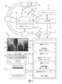
図1を参照すると、本開示のX線透視外科手術システムは、手術空間20内において手術テーブル21上に横臥状態で横になっている患者23を伴う外科手術処置を実行するために、X線透視イメージャ30(例えば、図示されるような移動式Cアーム)と、FORSセンサ40と、機械的コネクタ50と、任意の種類の外科手術器具60と、ナビゲーションコントローラ70とを用いる。
Referring to FIG. 1, the X-ray fluorosurgery surgical system of the present disclosure performs an X-ray procedure in a
当技術分野において知られるように、X線透視イメージャ30は、概して、X線生成器31と、画像増幅器32と、X線透視イメージャ30を回転させるための鍔部33とを含む。術中に、X線透視イメージャ30は、患者23の解剖学的エリアのX線透視画像を示す撮像データ34を生成する。
As is known in the art, the
FORSセンサ40は、制御された格子パターン(例えば、ファイバブラッグ格子)、特性後方散乱(例えば、レイリー後方散乱)又は光ファイバに埋め込まれ、エッチングされ、刻印され又は他の方法で形成された反射素子及び/又は透過素子の任意の他の配置を有する光ファイバを含む。実際には、制御された格子、特性後方散乱又は反射/透過素子は、光ファイバの任意の部分又はその全体に延在してよい。同じく実際には、FORSセンサ40は、螺旋状の又は螺旋状でない1つ又は複数の、又は個別のファイバを含んでよい。
The
実際には、FORSセンサ40の光ファイバは、部分的に又は全体的に、任意のガラス、シリカ、リン酸塩ガラス又は他のガラスで作られ、又は、ガラス及びプラスチック、プラスチック、又は光ファイバを形成するために使用される他の材料で作られる。手動又はロボット挿入によって患者の解剖学的構造内に導入されるときのFORSセンサ40への任意の損傷を防ぐために、FORSセンサ40の光ファイバは、医療デバイス(例えば、ガイドワイヤ又はカテーテル)内に埋め込まれ、又は保護スリーブによって恒久的に包囲される。実際には、保護スリーブは、ペバックス、ニチノール、分岐チューブ、撚り合わせ金属チューブを含むがそれらに限定されない、特定の硬さの任意の柔軟な材料から作られる。同じく実際には、保護スリーブは、重なり合う及び/又は連続的な配置の、同一の又は異なる程度の柔軟性及び硬さの2つ以上の管状のコンポーネントからなる。
In practice, the optical fiber of the
術中に、FORSセンサ40は、手術テーブル21のレール22Rに接合されるローンチ42から遠位方向に延在し、光ファイバ41は、ローンチ42から光結合器44に向かって近位方向に延在する。実際には、光ファイバ41は、ローンチ42においてFORSセンサ40に接続される別個の光ファイバであるか、又はFORSセンサ40の近位方向延長部である。
During the operation, the
当技術分野において知られるように、FORSコントローラ43は、光結合器44による光ファイバ41を介したFORSセンサ40内への発光を制御し、光はFORSセンサ40を通過してその遠位端部まで伝播し、手術空間20内において固定的な基準位置としての役割を果たすローンチ42に対するFORSセンサ40の形状再構成の情報を与える感知データ45を生成する。実際には、FORSセンサ40の遠位端部は、特には光を反射するFORSセンサ40の実施形態のためには閉塞され、又は、特には光を透過するFORSセンサ40の実施形態のためには開放されている。
As is known in the art, the
機械的コネクタ50は、図示されるようにX線生成器31において又は任意の他の適切な場所において、X線透視イメージャ30に接合され、本開示において更に説明されるように、X線透視イメージャ30にFORSセンサ40を取り外し可能に装着するために使用される。1つの実施形態において、機械的コネクタ50は、一体構成型のコネクタ50aである。代替的な実施形態において、機械的コネクタ50は、コネクタベース50bとコネクタクリップ50cとを含む複数部品構成型のコネクタである。
The
術中に、機械的コネクタ50は、FORSセンサ40を、画像取得フェーズ中には、取得されたX線透視撮像データ34が手術空間20(例えば、患者座標フレーム)内においてレジストレーションされるようにX線透視イメージャ30に対して、及び器具ナビゲーションフェーズ中には、手術空間内において外科手術器具60の位置及び向きを知ることができるように外科手術器具60に対して、二者択一的に装着する。
During surgery, the
ナビゲーションコントローラ60は、モニタ81、キーボード82、及びコンピュータ83の既知の配置を含むワークステーション80内に設置される。
The
ナビゲーションコントローラ70は、画像トラッカ71、器具トラッカ72、患者トラッカ73、及び外科手術アプリケーション74の形態のアプリケーションモジュールを含む。
The
FORSセンサ40が機械的コネクタ50を介してX線透視イメージャ30に装着された状態で、画像トラッカ71は、当技術分野において知られるようにX線透視イメージャ30に対する機械的コネクタ50a又はコネクタベース50bのキャリブレーションに基づき、当技術分野において知られるようにFORSセンサ40の形状再構成から導出される、手術空間20内におけるX線透視イメージャ30の位置及び向きを追跡する。
With the
FORSセンサ40が機械的コネクタ又は他の手段を介して外科手術器具60に装着された状態で、又は代替的に外科手術器具60に埋め込まれた状態で、器具トラッカ72は、当技術分野において知られるように外科手術器具60に対するFORSセンサ40のキャリブレーションに基づき、当技術分野において知られるようにFORSセンサ40の形状再構成から導出される、手術空間20内における外科手術器具60の位置及び向きを追跡する。
The
実際には、外科手術器具60が省略され得、これに限定されるわけではないがガイドワイヤとしての役割を果たすFORSセンサ40など、FORSセンサ40が追加的に外科手術器具としての役割を果たす。そのような実施形態については、器具トラッカ72は、当技術分野において知られるようにFORSセンサ40の形状再構成から導出される、手術空間20内における外科手術器具としての役割を果たすFORSセンサ40の位置及び向きを追跡する。
In practice, the
FORSセンサ40が任意の実行可能な手段によって患者23に装着された状態で、患者トラッカ73は、当技術分野において知られるようにFORSセンサの患者の解剖学的構造23に対するキャリブレーションに基づき、当技術分野において知られるようにFORSセンサ40の形状再構成から導出される、手術空間20内における患者23の運動を追跡する。
With the
外科手術アプリケーション74は、患者23内の外科手術器具60及びそれに装着されたツールの軌道及び位置決めを計画する画像計画アプリケーション、及びX線透視画像及び/又は手術画像(例えば、図示されているようなモニタ81によって表示される二面X線画像84及び85)上への外科手術器具60の重畳を表示するための画像誘導アプリケーションを含むがこれらに限定されない、外科手術処置を実施するための1つ又は複数の既知のアプリケーションを含む。手術画像の例としては、術前及び/又は術中のCT、MRI又はX線画像があるが、これらに限定されない。
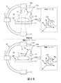
なおも図1を参照すると、本開示の様々な発明の理解を更に促進するために、図2A〜図2Fについての以下の説明は、機械的コネクタ50a(図1)を組み込んだX線透視外科手術システムによる外科手術処置中のFORS感知の実施態様の基本的な発明的な原理を教示する。この説明から、当業者は、機械的コネクタ50aを組み込んだ本開示のX線透視外科手術システム及び方法の追加的な実施形態を形成し、使用するために、どのように本開示の発明的な原理を適用するかを理解されよう。図2A〜図2Fに図示される本開示のコンポーネントは、縮尺通りに描かれているのではなく、本開示の発明的な原理を概念的に視覚化するために描かれていることに留意されたい。
Still referring to FIG. 1, in order to further facilitate the understanding of the various inventions of the present disclosure, the following description of FIGS. 2A-2F is an X-ray fluorosurgery incorporating a
図2Aを参照すると、示された外科手術処置の画像取得フェーズは、機械的コネクタ50a内へのFORSセンサ40aの埋め込みを介したX線透視イメージャ30へのFORSセンサ40aの取り外し可能な装着を伴う。これに先立ち、これと同時に、又はこれに続いて、画像取得フェーズは、X線透視イメージャ30によるX線35の射出を更に伴う。画像トラッカ71は、X線透視イメージャ30に装着されたFORSセンサ40aの形状再構成76aから導出される、手術空間20の座標系75(例えば、患者座標系)内における結果的なX線透視画像77の位置及び向きを追跡する。
Referring to FIG. 2A, the imaging phase of the surgical procedure shown involves the removable attachment of the
続く外科手術処置の器具ナビゲーションフェーズは、X線透視イメージャ30からのFORSセンサ40aの取り外し及び外科手術器具60内へのFORSセンサ40aの埋め込みを伴う。器具トラッカ72は、外科手術器具60に装着されたFORSセンサ40aの形状再構成78aから導出される、手術空間20の座標系75内における外科手術器具60の位置及び向きを追跡する。
The instrument navigation phase of the subsequent surgical procedure involves removal of the
図2Bを参照すると、示された外科手術処置の画像取得フェーズは、機械的コネクタ50aを貫通したFORSセンサ40bの埋め込みを介したX線透視イメージャ30へのFORSセンサ40bの取り外し可能な装着を伴う。これに先立ち、これと同時に、又はこれに続いて、画像取得フェーズは、X線透視イメージャ30によるX線35の射出を更に伴う。画像トラッカ71は、X線透視イメージャ30に装着されたFORSセンサ40bの形状再構成76bから導出される、手術空間20の座標系75(例えば、患者座標系)内における結果的なX線透視画像77の位置及び向きを追跡する。
Referring to FIG. 2B, the imaging phase of the surgical procedure shown involves the removable attachment of the
FORSセンサ40bは、FORSセンサ40aの長尺バージョンである(図2B)。そのため、続く外科手術処置の器具ナビゲーションフェーズは、機械的コネクタ50aを介したX線透視イメージャ30へのFORSセンサ40bの装着を維持しつつ、外科手術器具60内へのFORSセンサ40bの埋め込みを伴う。器具トラッカ72は、外科手術器具60に装着されたFORSセンサ40bの形状再構成78bから導出される、手術空間20の座標系75内における外科手術器具60の位置及び向きを追跡する。
The
図2Cを参照すると、示された外科手術処置の画像取得フェーズは、機械的コネクタ50a内へのFORSセンサ40aの埋め込みを介したX線透視イメージャ30へのFORSセンサ40aの取り外し可能な装着を伴う。これに先立ち、これと同時に、又はこれに続いて、画像取得フェーズは、X線透視イメージャ30によるX線35の射出を更に伴う。画像トラッカ71は、X線透視イメージャ30に装着されたFORSセンサ40aの形状再構成76aから導出される、手術空間20の座標系75(例えば、患者座標系)内における結果的なX線透視画像77の位置及び向きを追跡する。
Referring to FIG. 2C, the imaging phase of the surgical procedure shown involves the removable attachment of the
実際には、外科手術器具60は、ルーメンを有して構成されなくてもよく、又は本開示のFORSセンサ40のために使用可能な追加的なルーメンを有さなくてもよい。そのため、FORSセンサ40のためのルーメンを有する器具コネクタ61が、外科手術器具60内に一体化され得(例えば、器具コネクタ61は、外科手術器具60のコンポーネントとして製造され、又は外科手術器具60に恒久的に固定される)、又は外科手術器具60に(例えば、外科手術器具60の適切なコンポーネントへの取り外し可能なプレス嵌め又は磁気的締め付けによって)後付けされ得る。
In practice, the
器具コネクタ61に基づき、続く外科手術処置の器具ナビゲーションフェーズは、X線透視イメージャ30からのFORSセンサ40aの取り外し及び外科手術器具60にクリップ、締め付け又は他のやり方で接続された器具コネクタ61内へのFORSセンサ40aの埋め込みを伴う。器具トラッカ72は、外科手術器具60に装着されたFORSセンサ40aの形状再構成78aから導出される、手術空間20の座標系75内における外科手術器具60の位置及び向きを追跡する。
Based on the
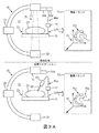
図2Dを参照すると、示された外科手術処置の画像取得フェーズは、機械的コネクタ50aを貫通したFORSセンサ40bの埋め込みを介したX線透視イメージャ30へのFORSセンサ40bの取り外し可能な装着を伴う。これに先立ち、これと同時に、又はこれに続いて、画像取得フェーズは、X線透視イメージャ30によるX線35の射出を更に伴う。画像トラッカ71は、X線透視イメージャ30に装着されたFORSセンサ40bの形状再構成76bから導出される、手術空間20の座標系75(例えば、患者座標系)内における結果的なX線透視画像77の位置及び向きを追跡する。
Referring to FIG. 2D, the imaging phase of the surgical procedure shown involves the removable attachment of the
続く外科手術処置の器具ナビゲーションフェーズは、機械的コネクタ50aを介したX線透視イメージャ30へのFORSセンサ40bの装着を維持しつつ、外科手術器具60にクリップ、締め付け又は他のやり方で接続された器具コネクタ61内へのFORSセンサ40bの埋め込みを伴う。器具トラッカ72は、外科手術器具60に装着されたFORSセンサ40bの形状再構成78bから導出される、手術空間20の座標系75内における外科手術器具60の位置及び向きを追跡する。
The instrument navigation phase of the subsequent surgical procedure was clipped, tightened or otherwise connected to the
図2Eを参照すると、示された外科手術処置の画像取得フェーズは、機械的コネクタ50a内へのFORSセンサ40aの埋め込みを介したX線透視イメージャ30へのFORSセンサ40aの取り外し可能な装着を伴う。これに先立ち、これと同時に、又はこれに続いて、画像取得フェーズは、X線透視イメージャ30によるX線35の射出を更に伴う。画像トラッカ71は、X線透視イメージャ30に装着されたFORSセンサ40aの形状再構成76aから導出される、手術空間20の座標系75(例えば、患者座標系)内における結果的なX線透視画像77の位置及び向きを追跡する。
Referring to FIG. 2E, the imaging phase of the surgical procedure shown involves the removable attachment of the
続く外科手術処置の器具ナビゲーションフェーズは、機械的コネクタ50aを介したX線透視イメージャ30へのFORSセンサ40aの装着を維持しつつ、外科手術器具60内への補助FORSセンサ46の埋め込みを伴う。器具トラッカ72は、外科手術器具60に装着された補助FORSセンサ46の形状再構成78cから導出される、手術空間20の座標系75内における外科手術器具60の位置及び向きを追跡する。
The instrument navigation phase of the subsequent surgical procedure involves implantation of the
図2Fを参照すると、示された外科手術処置の画像取得フェーズは、機械的コネクタ50a内へのFORSセンサ40aの埋め込みを介したX線透視イメージャ30へのFORSセンサ40aの取り外し可能な装着を伴う。これに先立ち、これと同時に、又はこれに続いて、画像取得フェーズは、X線透視イメージャ30によるX線35の射出を更に伴う。画像トラッカ71は、X線透視イメージャ30に装着されたFORSセンサ40aの形状再構成76aから導出される、手術空間20の座標系75(例えば、患者座標系)内における結果的なX線透視画像77の位置及び向きを追跡する。
Referring to FIG. 2F, the imaging phase of the surgical procedure shown involves the removable attachment of the
続く外科手術処置の器具ナビゲーションフェーズは、機械的コネクタ50aを介したX線透視イメージャ30へのFORSセンサ40aの装着を維持しつつ、外科手術器具60にクリップ、締め付け又は他のやり方で接続された器具コネクタ61内への補助FORSセンサ46の埋め込みを伴う。器具トラッカ72は、外科手術器具60に装着された補助FORSセンサ46の形状再構成78cから導出される、手術空間20の座標系75内における外科手術器具60の位置及び向きを追跡する。
The instrument navigation phase of the subsequent surgical procedure was clipped, tightened or otherwise connected to the
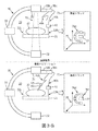
再び図1を参照すると、本開示の様々な発明の理解を更に促進するために、図3A〜図3Iについての以下の説明は、コネクタベース50b(図1)とコネクタクリップ50c(図1)とを含む機械的コネクタを組み込んだX線透視外科手術システムによる外科手術処置中のFORS感知の実施態様の基本的な発明的な原理を教示する。この説明から、当業者は、コネクタベース50bとコネクタクリップ50cとを組み込んだ本開示のX線透視外科手術システム及び方法の追加的な実施形態を形成し、使用するために、どのように本開示の発明的な原理を適用するかを理解されよう。図3A〜図3Iに図示される本開示のコンポーネントは、縮尺通りに描かれているのではなく、本開示の発明的な原理を概念的に視覚化するために描かれていることに留意されたい。
With reference to FIG. 1 again, in order to further facilitate the understanding of the various inventions of the present disclosure, the following description of FIGS. 3A-3I includes a
図3A〜図3Iを参照すると、コネクタベース50bはX線透視イメージャ30に接合され、コネクタクリップ50cはコネクタベース50bに取り外し可能に装着可能である。
Referring to FIGS. 3A-3I, the
図3Aを参照すると、示された外科手術処置の画像取得フェーズは、コネクタクリップ50c内へのFORSセンサ40aの埋め込みを介したX線透視イメージャ30へのFORSセンサ40aの取り外し可能な装着を伴う。これに先立ち、これと同時に、又はこれに続いて、画像取得フェーズは、X線透視イメージャ30によるX線35の射出を更に伴う。画像トラッカ71は、X線透視イメージャ30に装着されたFORSセンサ40aの形状再構成76cから導出される、手術空間20の座標系75(例えば、患者座標系)内における結果的なX線透視画像77の位置及び向きを追跡する。
Referring to FIG. 3A, the imaging phase of the surgical procedure shown involves the removable attachment of the
続く外科手術処置の器具ナビゲーションフェーズは、コネクタベース50bからのコネクタクリップ50cの取り外し及び外科手術器具60内へのコネクタベース50bのクリップ、締め付け又は他のやり方での接続を伴う。器具トラッカ72は、外科手術器具60に装着されたFORSセンサ40aの形状再構成78aから導出される、手術空間20の座標系75内における外科手術器具60の位置及び向きを追跡する。
The instrument navigation phase of the subsequent surgical procedure involves removing the
図3Bを参照すると、示された外科手術処置の画像取得フェーズは、コネクタクリップ50cを貫通したFORSセンサ40bの埋め込みを介したX線透視イメージャ30へのFORSセンサ40bの取り外し可能な装着を伴う。これに先立ち、これと同時に、又はこれに続いて、画像取得フェーズは、X線透視イメージャ30によるX線35の射出を更に伴う。画像トラッカ71は、X線透視イメージャ30に装着されたFORSセンサ40bの形状再構成76dから導出される、手術空間20の座標系75(例えば、患者座標系)内における結果的なX線透視画像77の位置及び向きを追跡する。
Referring to FIG. 3B, the imaging phase of the surgical procedure shown involves the removable attachment of the
本明細書において既に述べられたように、FORSセンサ40bは、FORSセンサ40aの長尺バージョンである(図3A)。そのため、続く外科手術処置の器具ナビゲーションフェーズは、コネクタベース50bからのコネクタクリップ50cの取り外し及び外科手術器具60内へのFORSセンサ40bの埋め込みを伴う。器具トラッカ72は、外科手術器具60に装着されたFORSセンサ40bの形状再構成78cから導出される、手術空間20の座標系75内における外科手術器具60の位置及び向きを追跡する。
As already mentioned herein, the
図3Cを参照すると、示された外科手術処置の画像取得フェーズは、コネクタクリップ50cを貫通したFORSセンサ40bの埋め込みを介したX線透視イメージャ30へのFORSセンサ40bの取り外し可能な装着を伴う。これに先立ち、これと同時に、又はこれに続いて、画像取得フェーズは、X線透視イメージャ30によるX線35の射出を更に伴う。画像トラッカ71は、X線透視イメージャ30に装着されたFORSセンサ40bの形状再構成76cから導出される、手術空間20の座標系75(例えば、患者座標系)内における結果的なX線透視画像77の位置及び向きを追跡する。
Referring to FIG. 3C, the imaging phase of the surgical procedure shown involves the removable attachment of the
続く外科手術処置の器具ナビゲーションフェーズは、コネクタベース50bからのコネクタクリップ50cの取り外し及び外科手術器具60にクリップ、締め付け又は他のやり方で接続された器具コネクタ61内へのFORSセンサ40bの埋め込みを伴う。器具トラッカ72は、外科手術器具60に装着されたFORSセンサ40bの形状再構成78cから導出される、手術空間20の座標系75内における外科手術器具60の位置及び向きを追跡する。
The instrument navigation phase of the subsequent surgical procedure involves removing the
図3Dを参照すると、示された外科手術処置の画像取得フェーズは、コネクタクリップ50c内へのFORSセンサ40aの埋め込みを介したX線透視イメージャ30へのFORSセンサ40aの取り外し可能な装着を伴う。これに先立ち、これと同時に、又はこれに続いて、画像取得フェーズは、X線透視イメージャ30によるX線35の射出を更に伴う。画像トラッカ71は、X線透視イメージャ30に装着されたFORSセンサ40aの形状再構成76cから導出される、手術空間20の座標系75(例えば、患者座標系)内における結果的なX線透視画像77の位置及び向きを追跡する。
Referring to FIG. 3D, the imaging phase of the surgical procedure shown involves the removable attachment of the
続く外科手術処置の器具ナビゲーションフェーズは、コネクタクリップ50cからのFORSセンサ40aの取り出し及び外科手術器具60を貫通したFORSセンサ40aの埋め込みを伴う。器具トラッカ72は、外科手術器具60に装着されたFORSセンサ40aの形状再構成78aから導出される、手術空間20の座標系75内における外科手術器具60の位置及び向きを追跡する。
The instrument navigation phase of the subsequent surgical procedure involves removing the
図3Eを参照すると、示された外科手術処置の画像取得フェーズは、コネクタクリップ50cを貫通したFORSセンサ40bの埋め込みを介したX線透視イメージャ30へのFORSセンサ40bの取り外し可能な装着を伴う。これに先立ち、これと同時に、又はこれに続いて、画像取得フェーズは、X線透視イメージャ30によるX線35の射出を更に伴う。画像トラッカ71は、X線透視イメージャ30に装着されたFORSセンサ40bの形状再構成76dから導出される、手術空間20の座標系75(例えば、患者座標系)内における結果的なX線透視画像77の位置及び向きを追跡する。
Referring to FIG. 3E, the imaging phase of the surgical procedure shown involves the removable attachment of the
続く外科手術処置の器具ナビゲーションフェーズは、コネクタクリップ50cを貫通したFORSセンサ40bの埋め込みを維持しつつ、外科手術器具60内へのFORSセンサ40bの埋め込みを伴う。器具トラッカ72は、外科手術器具60に装着されたFORSセンサ40bの形状再構成78dから導出される、手術空間20の座標系75内における外科手術器具60の位置及び向きを追跡する。
The instrument navigation phase of the subsequent surgical procedure involves implantation of the
図3Fを参照すると、示された外科手術処置の画像取得フェーズは、コネクタクリップ50c内へのFORSセンサ40aの埋め込みを介したX線透視イメージャ30へのFORSセンサ40aの取り外し可能な装着を伴う。これに先立ち、これと同時に、又はこれに続いて、画像取得フェーズは、X線透視イメージャ30によるX線35の射出を更に伴う。画像トラッカ71は、X線透視イメージャ30に装着されたFORSセンサ40aの形状再構成76cから導出される、手術空間20の座標系75(例えば、患者座標系)内における結果的なX線透視画像77の位置及び向きを追跡する。
Referring to FIG. 3F, the imaging phase of the surgical procedure shown involves the removable attachment of the
続く外科手術処置の器具ナビゲーションフェーズは、コネクタクリップ50cからのFORSセンサ40aの取り出し及び外科手術器具60にクリップ、締め付け又は他のやり方で接続された器具コネクタ61内へのFORSセンサ40aの埋め込みを伴う。器具トラッカ72は、外科手術器具60に装着されたFORSセンサ40aの形状再構成78aから導出される、手術空間20の座標系75内における外科手術器具60の位置及び向きを追跡する。
The instrument navigation phase of the subsequent surgical procedure involves removing the
図3Gを参照すると、示された外科手術処置の画像取得フェーズは、コネクタクリップ50cを貫通したFORSセンサ40bの埋め込みを介したX線透視イメージャ30へのFORSセンサ40bの取り外し可能な装着を伴う。これに先立ち、これと同時に、又はこれに続いて、画像取得フェーズは、X線透視イメージャ30によるX線35の射出を更に伴う。画像トラッカ71は、X線透視イメージャ30に装着されたFORSセンサ40bの形状再構成76dから導出される、手術空間20の座標系75(例えば、患者座標系)内における結果的なX線透視画像77の位置及び向きを追跡する。
Referring to FIG. 3G, the imaging phase of the surgical procedure shown involves the removable attachment of the
続く外科手術処置の器具ナビゲーションフェーズは、コネクタクリップ50cを貫通したFORSセンサ40bの埋め込みを維持しつつ、外科手術器具60にクリップ、締め付け又は他のやり方で接続された器具コネクタ61内へのFORSセンサ40bの埋め込みを伴う。器具トラッカ72は、外科手術器具60に装着されたFORSセンサ40bの形状再構成78dから導出される、手術空間20の座標系75内における外科手術器具60の位置及び向きを追跡する。
The instrument navigation phase of the subsequent surgical procedure maintains the implantation of the
図3Hを参照すると、示された外科手術処置の画像取得フェーズは、コネクタクリップ50c内へのFORSセンサ40aの埋め込みを介したX線透視イメージャ30へのFORSセンサ40aの取り外し可能な装着を伴う。これに先立ち、これと同時に、又はこれに続いて、画像取得フェーズは、X線透視イメージャ30によるX線35の射出を更に伴う。画像トラッカ71は、X線透視イメージャ30に装着されたFORSセンサ40aの形状再構成76dから導出される、手術空間20の座標系75(例えば、患者座標系)内における結果的なX線透視画像77の位置及び向きを追跡する。
Referring to FIG. 3H, the imaging phase of the surgical procedure shown involves the removable attachment of the
続く外科手術処置の器具ナビゲーションフェーズは、コネクタクリップ50c内へのFORSセンサ40aの埋め込みを維持しつつ、外科手術器具60内への補助FORSセンサ46の埋め込みを伴う。器具トラッカ72は、外科手術器具60に装着された補助FORSセンサ46の形状再構成78aから導出される、手術空間20の座標系75内における外科手術器具60の位置及び向きを追跡する。
The instrument navigation phase of the subsequent surgical procedure involves implanting the
図3Iを参照すると、示された外科手術処置の画像取得フェーズは、コネクタクリップ50c内へのFORSセンサ40aの埋め込みを介したX線透視イメージャ30へのFORSセンサ40aの取り外し可能な装着を伴う。これに先立ち、これと同時に、又はこれに続いて、画像取得フェーズは、X線透視イメージャ30によるX線35の射出を更に伴う。画像トラッカ71は、X線透視イメージャ30に装着されたFORSセンサ40aの形状再構成76aから導出される、手術空間20の座標系75(例えば、患者座標系)内における結果的なX線透視画像77の位置及び向きを追跡する。
Referring to FIG. 3I, the imaging phase of the surgical procedure shown involves the removable attachment of the
続く外科手術処置の器具ナビゲーションフェーズは、コネクタクリップ50cを介したX線透視イメージャ30へのFORSセンサ40aの装着を維持しつつ、外科手術器具60にクリップ、締め付け又は他のやり方で接続された器具コネクタ61内への補助FORSセンサ46の埋め込みを伴う。器具トラッカ72は、外科手術器具60に装着された補助FORSセンサ46の形状再構成78aから導出される、手術空間20の座標系75内における外科手術器具60の位置及び向きを追跡する。
The instrument navigation phase of the subsequent surgical procedure is an instrument clipped, tightened or otherwise connected to the
再び図1を参照すると、本開示のX線透視イメージャ30、FORSセンサ40及び機械的コネクタ50は、二面画像84及び85によって図示されるように、二面撮像に殊に適しているものとして説明されているが、実際には、X線透視イメージャ30、FORSセンサ40及び機械的コネクタ50は、単一のX線透視撮像にも適している。このために、図1に図示されるように、手術空間20内に固定的な基準ポイントを確立するために、ローンチ42がやはり利用され、又は代替的に、図4に図示されるように、ローンチ42は省略され、光ファイバ41は、(機械的コネクタ50aの形態の、又はコネクタベース50b及びコネクタクリップ50cの形態の)機械的コネクタ50から光結合器44へと近位方向に延在する。
With reference to FIG. 1 again, the
図4を参照すると、FORSセンサ40は、機械的コネクタ50から遠位方向に延在し、機械的コネクタ50が、X線透視イメージャ30の任意の運動と同期して移動可能な手術空間20内の基準ポイントとしての役割を果たし、又は代替的に、基準ポイントは、X線透視イメージャ30の固定的な場所(例えば、図示される固定的な場所47)に確立される。加えて、X線透視イメージャ30と外科手術器具60との間の空間的関係を追跡する目的で、本明細書において前述された本開示の発明的な原理によって、FORSセンサ40は、外科手術器具60又は器具コネクタ(不図示)に埋め込まれ又は他のやり方で装着される。X線透視イメージャ30と外科手術器具60との間の空間的関係の追跡は、画像誘導アプリケーションによる、X線透視画像(例えば、図示されているようなモニタ81によって表示されるX線透視画像86)上への外科手術器具60の重畳の表示を容易にする。
Referring to FIG. 4, the
図1及び図4を参照すると、本開示の様々な発明の理解を更に促進するために、図5A,図5B,図6A及び図6Bについての以下の説明は、機械的コネクタ50a、コネクタクリップ50c及び外科手術器具60並びに器具コネクタ61(図2C)内への又はそれらを貫通してのFORSセンサ40の埋め込みを組み込んだX線透視外科手術システムによる外科手術処置中のFORS感知の実施態様の基本的な発明的な原理を教示する。この説明から、当業者は、FORSセンサ40のそのような埋め込みを組み込んだ本開示のX線透視外科手術システム及び方法の追加的な実施形態を形成し、使用するために、どのように本開示の発明的な原理を適用するかを理解されよう。図5A,図5B,図6A及び図6Bに図示される本開示のコンポーネントは、縮尺通りに描かれているのではなく、本開示の発明的な原理を概念的に視覚化するために描かれていることに留意されたい。
With reference to FIGS. 1 and 4, in order to further facilitate the understanding of the various inventions of the present disclosure, the following description of FIGS. 5A, 5B, 6A and 6B describes the
図5Aを参照すると、FORSセンサ40は、ローンチ42から遠位方向に延在し、オブジェクト90のルーメン91内に挿入可能(I)及びそこから後退可能(R)であるような大きさの直径を有し、オブジェクト90は、機械的コネクタ50a(図1)、外科手術器具60(図1)及び器具コネクタ61(図2C)を表す。実際には、オブジェクト90のルーメン91内への挿入に際して、FORSセンサ40の意図される追跡用途に応じて、FORSセンサ40は、オブジェクト90のルーメン91を部分的に又は全体的に占有し、又はオブジェクト90のルーメン91を貫通してその外まで延在する。
Referring to FIG. 5A, the
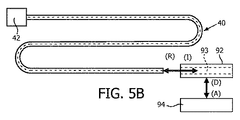
図5Bを参照すると、FORSセンサ40は、ローンチ42から遠位方向に延在し、オブジェクト92のルーメン93内に挿入可能(I)及びそこから後退可能(R)であるような大きさの直径を有し、オブジェクト92は、コネクタクリップ50c(図1)を表す。オブジェクト92は、オブジェクト94に装着可能(A)及びそこから取り外し可能(D)であり、オブジェクト94は、コネクタベース50b(図1)及び外科手術器具60(図1)を表す。実際には、オブジェクト92のルーメン93内への挿入に際して、FORSセンサ40の意図される追跡用途に応じて、FORSセンサ40は、オブジェクト92のルーメン93を部分的に又は全体的に占有し、又はオブジェクト92のルーメン93を貫通してその外まで延在する。
With reference to FIG. 5B, the
図6Aを参照すると、機械的コネクタ50a(図1)又はコネクタクリップ50c(図1)は、クリップ100aとして具現化され、クリップ100aは、クリップ100a内へのFORSセンサ40の摩擦嵌合式の挿入及び後退のための、又は代替的にクリップ100a内へのFORSセンサ40の恒久的な埋め込みのための半楕円形のルーメン101aを有する。ルーメン101aは、クリップ100aを貫通したFORSセンサ40の摩擦嵌合式の挿入及び後退のための延長部101bを有してもよい。
Referring to FIG. 6A, the
図6Bを参照すると、機械的コネクタ50a(図1)又はコネクタクリップ50c(図1)は、クリップ100bとして具現化され、クリップ100bは、クリップ100b内へのFORSセンサの挿入及び後退のためのルーメン102aと、FORSセンサ40をルーメン102a内に一時的に又は恒久的に固定するために、ルーメン102aと交差するチャンネル102を貫通して延在するスクリュー104とを有する。ルーメン102aは、クリップ100bを貫通したFORSセンサ40の摩擦嵌合式の挿入及び後退のための延長部102bを有してもよい。
With reference to FIG. 6B, the
再び図1及び図4を参照すると、実際には、本開示のX線透視外科手術システムは、典型的には、無菌ドレープによって覆われており、本開示の装着方法は、ドレープの存在を考慮可能でなければならず、しかもなおX線透視イメージャ30へのFORSセンサ40の反復的な装着を促進しなければならない。図7A〜図7Dは、ドレープの組み込みに対処する本開示の例示的な実施形態を示す。
Referring again to FIGS. 1 and 4, in practice, the fluoroscopic surgical system of the present disclosure is typically covered by a sterile drape, and the wearing method of the present disclosure considers the presence of the drape. It must be possible, and yet it must facilitate the repetitive attachment of the
図7Aを参照すると、図示されるように、無菌ドレープ110は機械的コネクタ50aと一体化される。この実施形態については、機械的コネクタ50aは、無菌のものでなければならず、又は外科手術処置間に滅菌されなければならない。
With reference to FIG. 7A, as shown, the
図7Bを参照すると、図示されるように、無菌ドレープ110はコネクタベース50bと一体化される。この実施形態については、コネクタベース50b及びコネクタクリップ50cは、無菌のものでなければならず、又は外科手術処置間に滅菌されなければならない。
With reference to FIG. 7B, the
図7Cを参照すると、図示されるように、無菌ドレープ110はコネクタクリップ50cと一体化される。この実施形態については、コネクタクリップ50cは、無菌のものでなければならず、又は外科手術処置間に滅菌されなければならない。
With reference to FIG. 7C, as shown, the
図7Dを参照すると、図示されるように、無菌ドレープ110はコネクタベース50bとコネクタクリップ50cとの間に設置され、無菌ドレープ110は、コネクタベース50bへのコネクタクリップ50cの装着によって穴を開けられても開けられなくてもよい。この実施形態については、コネクタクリップ50cは、無菌のものでなければならず、又は外科手術処置間に滅菌されなければならない。
With reference to FIG. 7D, as shown, the
次に、本明細書において、レジストレーションフェーズ、キャリブレーションフェーズ、及び追跡フェーズを含むX線透視外科手術システムの例示的なワークフローが、図3Aのコンテキストにおいて説明される。この説明から、当業者は、更なるワークフロー実施形態に、どのように本開示の発明的な原理を適用するかを理解されよう。より具体的には、実際には、本開示のワークフロー実施形態は、全てのコンポーネントについてレジストレーションフェーズ及びキャリブレーションフェーズを必要とするものではない。例えば、本開示の様々な発明の利点の1つは、X線透視イメージャ30及びFORSセンサ40が、手術空間20内のローンチ42又は任意の他の固定的な基準位置の使用を通じて、互いに対して自動的にレジストレーションされることである。加えて、実際には、X線透視イメージャ30と機械的コネクタ50との間のキャリブレーションは、典型的には必要とされず、もしも2つ以上のFORSセンサが用いられるなら、FORSセンサは、当技術分野において知られる多くのレジストレーション技術のうちの1つによって、互いに対してレジストレーションされる。
Next, an exemplary workflow of a fluoroscopic surgical system including a registration phase, a calibration phase, and a follow-up phase is described herein in the context of FIG. 3A. From this description, one of ordinary skill in the art will understand how to apply the inventive principles of the present disclosure to further workflow embodiments. More specifically, in practice, the workflow embodiments of the present disclosure do not require a registration phase and a calibration phase for all components. For example, one of the advantages of the various inventions of the present disclosure is that the
レジストレーションフェーズ(FORSセンサ40):システムのユーザは、当技術分野において知られるように、光結合器44へのFORSセンサ40の結合を介してX線透視外科手術システムをセットアップし、手術テーブル21のレール22Rにローンチ42を装着する。続いてユーザは、FORSセンサ40のローンチ位置又はローンチ42から遠位方向に離間したFORSセンサ40の別のレジストレーション位置を、患者の解剖学的構造23の術前画像にレジストレーションするために、必要に応じて、キーボード82を介してナビゲーションコントローラ70のレジストレーションモジュール(不図示)を作動させる。実際には、レジストレーションモジュールによって任意の知られた適用可能なレジストレーション技術が実行される。
Registration Phase (FORS Sensor 40): The user of the system sets up the X-ray fluoroscopic surgery system through the coupling of the
キャリブレーションフェーズ(FORSセンサ40/機械的コネクタ50):X線透視外科手術システムのユーザは、本明細書において前述されたように、コネクタクリップ50c内への又はそこを貫通してのFORSセンサ40の挿入を介して、X線透視イメージャ30にFORSセンサ40をしっかりと装着する。続いてユーザは、FORSセンサ40をX線透視イメージャ30に対してキャリブレーションするために、必要に応じて、キーボード82を介してナビゲーションコントローラ70のキャリブレーションモジュール(不図示)を作動させる。
Calibration Phase (
より具体的には、キャリブレーションは、FORSセンサ40とコネクタクリップ50cとの間の強固な関係を前提としている。そのため、実際には、FORSセンサ40及びX線透視イメージャ30をキャリブレーションするために、任意の知られた適用可能なキャリブレーション技術が実行される。
More specifically, the calibration presupposes a strong relationship between the
知られたキャリブレーション技術に変わって、本開示は、本開示のコネクタクリップ50cに固有のルーメン形状によるコネクタクリップ50cの自動的な検知及びキャリブレーションを伴うキャリブレーション技術を提供する。詳細には、FORSセンサ40がコネクタクリップ50cのルーメン内に又はそこを貫通して挿入されると、ナビゲーションコントローラ70のキャリブレーションモジュールは、FORSセンサ40の形状再構成の1つ又は複数の形状パラメータ(曲率、位置、向き、軸歪みなど)に基づいて、X線透視イメージャ30を自動的に検知する。
In lieu of known calibration techniques, the present disclosure provides calibration techniques with automatic detection and calibration of the
追跡フェーズ(X線透視イメージャ30):FORSセンサ40のレジストレーション及びX線透視イメージャ30に対するFORSセンサ40のキャリブレーションが完了すると、イメージャトラッカ71は、当技術分野において知られるように、FORSセンサ40の形状再構成から導出される、手術空間20内におけるX線透視イメージャ30の位置及び向きの追跡を制御する。実際には、X線透視イメージャ30のための追跡フェーズは、X線透視イメージャ30が患者の解剖学的構造23に対して回転されるたびに実施される。
Tracking phase (X-ray fluoroscopic imager 30): Once the registration of the
キャリブレーションフェーズ(FORSセンサ40/外科手術器具60):X線透視外科手術システムのユーザは、コネクタベース50bからコネクタクリップ50cを取り外し、外科手術器具60にコネクタクリップ50cを装着する。続いてユーザは、FORSセンサ40を外科手術器具60に対してキャリブレーションするために、必要に応じて、キーボード112を介してキャリブレーションモジュール112を作動させる。続いてユーザは、FORSセンサ40を外科手術器具60に対してキャリブレーションするために、必要に応じて、キーボード82を介してナビゲーションコントローラ70のキャリブレーションモジュール(不図示)を作動させる。より具体的には、キャリブレーションは、FORSセンサ40と外科手術器具60との間の強固な関係を前提としている。そのため、実際には、FORSセンサ40及びX線透視イメージャ30をキャリブレーションするために、任意の知られた適用可能なキャリブレーション技術が実行される。
Calibration phase (
追跡フェーズ(外科手術器具60)。FORSセンサ40のレジストレーション及び外科手術器具60に対するFORSセンサ40のキャリブレーションが完了すると、器具トラッカ72は、当技術分野において知られるように、FORSセンサ40の形状再構成から導出される、手術空間20内における外科手術器具60の位置及び向きの追跡を制御する。
Follow-up phase (surgical instrument 60). Once the registration of the
実際には、画像誘導が実施されて、外科手術器具60がデータベースから選択され、次いで外科手術器具60のモデルが、FORSセンサ40の形状感知位置及び向きに基づいて、表示される。
In practice, image guidance is performed and the
同じく実際には、撮像誘導のための追跡精度は、所望の通りに改善される。 Also in practice, the tracking accuracy for imaging guidance is improved as desired.
例えば、画像ベースの改善は、システムのユーザが、画像重畳における外科手術器具60の先端部を特定することを伴い、それによりFORSセンサ40の遠位端部と外科手術器具60との間の距離が測定され、次いでFORSセンサ40の形状を適切な量だけ外挿するために使用される。もしも外科手術器具60の長手方向のものではない著しい誤差があるなら、この誤差は検知され、ユーザに特定される。
For example, an image-based improvement involves the user of the system identifying the tip of the
更なる例によって、キャリブレーション前に、ユーザはコネクタクリップ50cを、ローンチ60の特定の位置(又は別の既知の位置)に設置し、この既知の位置とFORSセンサ40の遠位端部の測定位置との間の距離が計算される。もしもFORSセンサ40の遠位端部の長手方向のものではない著しい誤差があるなら、この誤差は検知され、ユーザに特定される。
By a further example, prior to calibration, the user places the
更なる例によって、FORSセンサ40の先端部とFORSセンサ40の先端部の測定値との間の長手方向のオフセットを判定するための知られた技術の実行は、ユーザによってピボット固定を通じて実施される。
By a further example, the implementation of a known technique for determining the longitudinal offset between the tip of the
図1〜図7を参照すると、移動式Cアームを使用した典型的な整形外科ワークフローへのFORS感知の統合に特有のいくつかの課題の克服を含むがそれらに限定されない本発明の多くの利点を、当業者は理解されよう。特には、本開示のソリューションは、単一のFORSセンサの好ましい使用を提案し、このことはいくつかの理由で有益である。 With reference to FIGS. 1-7, many advantages of the invention, including but not limited to overcoming some of the challenges inherent in integrating FORS sensing into a typical orthopedic workflow using a mobile C-arm. Those skilled in the art will understand. In particular, the solutions of the present disclosure suggest the preferred use of a single FORS sensor, which is beneficial for several reasons.
第1に、複数の作動状態のFORSセンサの使用は、追加的なコストがかかる。本開示は複数の作動状態のFORSセンサにも適用可能であるが、本開示のソリューションは、処置中に単一のFORSセンサだけが使用されることを可能にする。 First, the use of multiple operating FORS sensors comes at an additional cost. Although the present disclosure is applicable to multiple operating FORS sensors, the solution of the present disclosure allows only a single FORS sensor to be used during the procedure.
第2に、単一のFORSセンサは、複雑さを減じ、ワークフローを向上させ、ワークスペースにおける乱雑さを減少させる。 Second, a single FORS sensor reduces complexity, improves workflow, and reduces clutter in the workspace.
第3に、単一のFORSセンサは、室内の停止した位置に固定されるので、撮像とナビゲーションとの間のシームレスなレジストレーションが提供される。 Third, the single FORS sensor is fixed in a stationary position in the room, providing seamless registration between imaging and navigation.
最後に、処置のワークフローは、しばしば、Cアームを患者から離れるように移動して、より良好なアクセスを提供することを伴う。本開示のソリューションは、このワークフローを容易にする。 Finally, treatment workflows often involve moving the C-arm away from the patient to provide better access. The solution of the present disclosure facilitates this workflow.
更に、本明細書において提供される教示に鑑みて、当業者は理解されようが、本開示/明細書において説明され及び/又は図面において描かれた特徴、要素、コンポーネントなどは、ハードウェア及びソフトウェアの様々な組み合わせにおいて実施され得、単一の要素又は複数の要素において組み合わせられ得る機能を提供する。例えば、図面において図示され/示され/描かれた様々な特徴、要素、コンポーネントなどの機能は、専用のハードウェアの使用、及び追加的な機能性のための適切なソフトウェアと関連したソフトウェアを実行可能なハードウェアの使用を通じて提供され得る。プロセッサによって提供される場合、機能は、単一の専用プロセッサによって、単一の共有されたプロセッサによって、又はそのうちのいくつかが共有及び/又は多重化され得る複数の個別のプロセッサによって提供され得る。更には、「プロセッサ」又は「コントローラ」という用語の明示的な使用は、ソフトウェアを実行可能なハードウェアを排他的に指すものと解釈されるべきではなく、限定的ではないが、デジタル信号プロセッサ(「DSP」)ハードウェア、メモリ(例えば、ソフトウェアを記憶するための読み出し専用メモリ(「ROM」)、ランダムアクセスメモリ(「RAM」)、不揮発性記憶装置など)及びプロセスを実行及び/又は制御することが可能な(及び/又はそのように構成可能な)事実上いかなる手段及び/又はマシン(ハードウェア、ソフトウェア、ファームウェア、それらの組み合わせなどを含む)も暗示的に含み得る。 Further, as will be appreciated by those skilled in the art in light of the teachings provided herein, features, elements, components, etc. described in this disclosure / specification and / or depicted in the drawings are hardware and software. It provides a function that can be implemented in various combinations of and can be combined in a single element or in multiple elements. For example, features such as various features, elements, components illustrated / shown / drawn in drawings use dedicated hardware and perform software associated with appropriate software for additional functionality. Can be provided through the use of possible hardware. When provided by a processor, functionality may be provided by a single dedicated processor, by a single shared processor, or by multiple individual processors, some of which may be shared and / or multiplexed. Furthermore, the explicit use of the term "processor" or "controller" should not be construed as exclusively referring to the hardware capable of running the software, and is not limited to digital signal processors ( "DSP") Runs and / or controls hardware, memory (eg, read-only memory ("ROM") for storing software, random access memory ("RAM"), non-volatile storage, etc.) and processes. Virtually any means and / or machines (including hardware, software, firmware, combinations thereof, etc.) capable (and / or so configurable) may be implied.
更には、本発明の原理、態様、及び実施形態並びにそれらの特定の例を列挙する本明細書における全ての記述は、それらの構造的及び機能的均等物の両方を包含することが意図される。加えて、そのような均等物は現在知られている均等物及び将来的に開発される均等物(例えば、構造に関わらず同一の又は実質的に同様の機能を実施し得る、開発される任意の要素)の両方を含むことが意図される。従って、例えば、本明細書において提供される教示に鑑みて、本明細書において提示される任意のブロック図は、本発明の原理を具現化する例示的なシステムコンポーネント及び/又は回路の概念図を表現し得ることが、当業者には理解されよう。同様に、本明細書において提供される教示に鑑みて、任意のフローチャート、フロー図などは、コンピュータ可読記憶媒体において実質的に表現され得、コンピュータ、プロセッサ又は処理能力を有する他のデバイスによってそのように実行され得る様々なプロセスを、そのようなコンピュータ又はプロセッサが明示的に図示されているか否かに関わらず、表現し得ることを当業者は理解するはずである。 Furthermore, all descriptions herein listing the principles, embodiments, and embodiments of the invention and specific examples thereof are intended to include both their structural and functional equivalents. .. In addition, such equivalents are currently known equivalents and future developed equivalents (eg, any developed equivalents that may perform the same or substantially similar function regardless of structure. It is intended to include both (elements of). Thus, for example, in view of the teachings provided herein, any block diagram presented herein provides a conceptual diagram of exemplary system components and / or circuits that embody the principles of the present invention. Those skilled in the art will understand that it can be expressed. Similarly, in view of the teachings provided herein, any flowchart, flow diagram, etc. may be substantially represented in a computer-readable storage medium, such as by a computer, processor or other device capable of processing. It should be appreciated by those skilled in the art that various processes that can be performed on can be represented, whether or not such a computer or processor is explicitly illustrated.
新規的で発明的なX線透視ベースの外科手術処置のための光ファイバリアルシェイプ感知の好ましい、例示的な実施形態が説明されたが(これらの実施形態は例示的なものであると意図され、限定的であることを意図されない)、図面を含む本明細書において提供される教示に照らして、修正及び変形が当業者によってなされ得ることに留意されたい。従って、本明細書において開示される実施形態の範囲内にある本開示の好ましい、例示的な実施形態において/に対して、変更がなされ得ることを理解されたい。 Preferred, exemplary embodiments of fiber optic real-shape sensing for novel and invention fluoroscopic-based surgical procedures have been described (these embodiments are intended to be exemplary). , Not intended to be limiting), it should be noted that modifications and modifications may be made by one of ordinary skill in the art in light of the teachings provided herein, including drawings. Therefore, it should be understood that changes may be made to / in the preferred, exemplary embodiments of the present disclosure that are within the scope of the embodiments disclosed herein.
更には、本開示によるデバイス/システムなどを組み込んだ及び/又は実現する対応する及び/又は関連するシステム、又は本開示によるデバイスにおいて/デバイスとともに使用/実現され得るものなども、本発明の範囲内にあるものと想定され、考えられることが、想定される。更に、本開示によるデバイス及び/又はシステムを製造及び/又は使用するための対応する及び/又は関連する方法も、本発明の範囲内にあるものと想定され、考えられる。 Furthermore, the corresponding and / or related systems incorporating and / or realizing the devices / systems according to the present disclosure, or those which can be used / realized together with the devices according to the present disclosure are also within the scope of the present invention. It is assumed that it is in, and it is assumed that it is possible. Further, corresponding and / or related methods for manufacturing and / or using the devices and / or systems according to the present disclosure are also assumed and considered to be within the scope of the present invention.
Claims (14)
X線透視イメージャと、
前記X線透視イメージャに接合される機械的コネクタであって、前記X線透視イメージャに前記FORSセンサを取り外し可能に装着するように構造的に構成される、機械的コネクタと、
前記機械的コネクタへの前記FORSセンサの取り外し可能な装着に基づき、前記FORSセンサによる前記感知データの生成に応答して、前記手術空間内における前記X線透視イメージャの追跡を制御するナビゲーションコントローラと
を備える、X線透視外科手術システムにおいて、前記X線透視外科手術システムは、
前記基準位置としての役割を果たすローンチを更に備え、
前記FORSセンサは、前記ローンチから遠位方向に延在し、
前記基準位置は、前記手術空間内において固定されている、
ことを特徴とする、X線透視外科手術システム。 A FORS sensor, which is a FORS sensor and generates sensing data that gives information on the shape reconstruction of the FORS sensor with respect to a reference position in the surgical space.
X-ray fluoroscopic imager and
Wherein a mechanical connector that is joined to the X-ray fluoroscopic imager, Ru is structurally configured can be attached removably to the FORS sensor to the X-ray fluoroscopic imager, a mechanical connector,
A navigation controller that controls the tracking of the X-ray fluoroscopic imager in the surgical space in response to the generation of the sensed data by the FORS sensor based on the removable attachment of the FORS sensor to the mechanical connector. In the X-ray fluoroscopy surgical system , the X-ray fluoroscopy surgical system is provided.
Further equipped with a launch that serves as the reference position,
The FORS sensor extends distally from the launch and
The reference position is fixed within the surgical space,
An X-ray fluoroscopic surgery system characterized by this .
を更に備える、請求項1に記載のX線透視外科手術システム。 The X-ray fluoroscopic surgical system according to claim 1, further comprising a drape integrated with the mechanical connector.
前記X線透視イメージャに接合されたコネクタベースと、
前記コネクタベースに前記FORSセンサを取り外し可能に装着するコネクタクリップと
を含む、請求項1に記載のX線透視外科手術システム。 The mechanical connector
With the connector base joined to the X-ray fluoroscopic imager,
The X-ray fluoroscopic surgical system according to claim 1, wherein the connector base includes a connector clip that detachably attaches the FORS sensor.
前記コネクタクリップによる前記コネクタベースへの前記FORSセンサの前記装着は、前記ドレープが前記コネクタベースと前記コネクタクリップとの間に設置されることを含む、請求項4に記載のX線透視外科手術システム。 With more drapes
The X-ray fluoroscopic surgical system according to claim 4, wherein the attachment of the FORS sensor to the connector base by the connector clip comprises installing the drape between the connector base and the connector clip. ..
前記FORSセンサは、前記外科手術器具内に埋め込まれ、
前記ナビゲーションコントローラは更に、前記外科手術器具内への前記FORSセンサの埋め込みに基づき、前記FORSセンサによる前記感知データの生成に応答して、前記手術空間内における前記外科手術器具の追跡を制御する、請求項1に記載のX線透視外科手術システム。 With more surgical instruments
The FORS sensor is embedded within the surgical instrument,
The navigation controller further controls the tracking of the surgical instrument in the surgical space in response to the generation of the sensing data by the FORS sensor based on the implantation of the FORS sensor in the surgical instrument . The X-ray fluorosurgery surgical system according to claim 1.
前記コネクタクリップは更に、前記外科手術器具に前記FORSセンサを取り外し可能に装着し、
前記ナビゲーションコントローラは更に、前記コネクタクリップによる前記外科手術器具への前記FORSセンサの取り外し可能な装着に基づき、前記FORSセンサによる前記感知データの生成に応答して、前記手術空間内における前記外科手術器具の追跡を制御する、請求項4に記載のX線透視外科手術システム。 With more surgical instruments
The connector clip further attaches the FORS sensor to the surgical instrument in a removable manner .
The navigation controller further responds to the generation of the sensing data by the FORS sensor based on the removable attachment of the FORS sensor to the surgical instrument by the connector clip, and the surgical instrument in the surgical space. The X-ray fluorosurgery surgical system according to claim 4 , which controls the tracking of.
前記外科手術器具に前記FORSセンサを取り外し可能に装着する器具コネクタと
を更に備え、
前記ナビゲーションコントローラは更に、前記器具コネクタによる前記外科手術器具への前記FORSセンサの取り外し可能な装着に基づき、前記FORSセンサによる前記感知データの生成に応答して、前記手術空間内における前記外科手術器具の追跡を制御する、請求項1に記載のX線透視外科手術システム。 Surgical instruments and
The surgical instrument is further provided with an instrument connector for detachably attaching the FORS sensor.
The navigation controller is further the basis by instrument connector to the FORS removable mounting of the sensor to the surgical instrument, in response to the generation of the sensing data by the FORS sensor, the surgical instrument in the operative space The X-ray fluorosurgery surgical system according to claim 1 , which controls the tracking of.
補助FORSセンサであって、前記手術空間内の前記基準位置に対する前記補助FORSセンサの形状再構成の情報を与える補助感知データを生成する、補助FORSセンサと
を更に備え、
前記補助FORSセンサは、前記外科手術器具内に埋め込まれ、
前記ナビゲーションコントローラは更に、前記外科手術器具内への前記補助FORSセンサの埋め込みに基づき、前記補助FORSセンサによる前記補助感知データの生成に応答して、前記手術空間内における前記外科手術器具の追跡を制御する、請求項1に記載のX線透視外科手術システム。 Surgical instruments and
An auxiliary FORS sensor, it generates the auxiliary sensor data to provide the auxiliary FORS information shape reconstruction of the sensor to the reference position of the surgical space, further comprising an auxiliary FORS sensor,
The auxiliary FORS sensor is embedded within the surgical instrument,
The navigation controller further tracks the surgical instrument in the surgical space in response to the generation of the auxiliary sensing data by the auxiliary FORS sensor based on the implantation of the auxiliary FORS sensor in the surgical instrument. The X-ray fluorosurgery surgical system according to claim 1 , which is controlled.
補助FORSセンサであって、前記手術空間内の前記基準位置に対する前記補助FORSセンサの形状再構成の情報を与える補助感知データを生成する、補助FORSセンサと
を更に備え、
前記コネクタクリップは更に、前記外科手術器具に前記補助FORSセンサを取り外し可能に装着し、
前記ナビゲーションコントローラは更に、前記コネクタクリップによる前記外科手術器具への前記補助FORSセンサの取り外し可能な装着に基づき、前記補助FORSセンサによる前記補助感知データの生成に応答して、前記手術空間内における前記外科手術器具の追跡を制御する、請求項4に記載のX線透視外科手術システム。 Surgical instruments and
An auxiliary FORS sensor, it generates the auxiliary sensor data to provide the auxiliary FORS information shape reconstruction of the sensor to the reference position of the surgical space, further comprising an auxiliary FORS sensor,
The connector clip further the mounted removably auxiliary FORS sensor to the surgical instrument,
The navigation controller further responds to the generation of the auxiliary sensing data by the auxiliary FORS sensor based on the removable attachment of the auxiliary FORS sensor to the surgical instrument by the connector clip, said the navigation controller in the surgical space. The X-ray fluoroscopic surgical system according to claim 4 , which controls the tracking of surgical instruments.
補助FORSセンサであって、前記手術空間内の前記基準位置に対する前記補助FORSセンサの形状再構成の情報を与える補助感知データを生成する、補助FORSセンサと、
前記外科手術器具に前記補助FORSセンサを取り外し可能に装着する器具コネクタと
を更に備え、
前記ナビゲーションコントローラは更に、前記器具コネクタによる前記外科手術器具への前記補助FORSセンサの取り外し可能な装着に基づき、前記補助FORSセンサによる前記補助感知データの生成に応答して、前記手術空間内における前記外科手術器具の追跡を制御する、請求項1に記載のX線透視外科手術システム。 Surgical instruments and
An auxiliary FORS sensor, generates the auxiliary sensor data to provide the auxiliary FORS information shape reconstruction of the sensor to the reference position of the surgical space, an auxiliary FORS sensor,
The surgical instrument is further provided with an instrument connector for detachably attaching the auxiliary FORS sensor.
The navigation controller further responds to the generation of the auxiliary sensing data by the auxiliary FORS sensor based on the removable attachment of the auxiliary FORS sensor to the surgical instrument by the instrument connector, said the navigation controller in the surgical space. The X-ray fluoroscopic surgical system according to claim 1 , which controls the tracking of surgical instruments.
Applications Claiming Priority (3)
| Application Number | Priority Date | Filing Date | Title |
|---|---|---|---|
| US201562186874P | 2015-06-30 | 2015-06-30 | |
| US62/186,874 | 2015-06-30 | ||
| PCT/IB2016/053557 WO2017001959A1 (en) | 2015-06-30 | 2016-06-16 | Fiber-optical realshape sensing for fluoroscopic surgical navigation |
Publications (3)
| Publication Number | Publication Date |
|---|---|
| JP2018524089A JP2018524089A (en) | 2018-08-30 |
| JP2018524089A5 JP2018524089A5 (en) | 2019-07-18 |
| JP6790000B2 true JP6790000B2 (en) | 2020-11-25 |
Family
ID=56296869
Family Applications (1)
| Application Number | Title | Priority Date | Filing Date |
|---|---|---|---|
| JP2017567699A Active JP6790000B2 (en) | 2015-06-30 | 2016-06-16 | Fiber Optic Real Shape Sensing for X-ray Fluoroscopic Surgery Navigation |
Country Status (4)
| Country | Link |
|---|---|
| US (1) | US10939889B2 (en) |
| EP (1) | EP3316786B1 (en) |
| JP (1) | JP6790000B2 (en) |
| WO (1) | WO2017001959A1 (en) |
Families Citing this family (5)
| Publication number | Priority date | Publication date | Assignee | Title |
|---|---|---|---|---|
| FR3068880A1 (en) * | 2017-07-11 | 2019-01-18 | Thales | METHOD AND SYSTEM FOR ONLINE CALIBRATION OF MEDICAL DEVICE WITH X-RAYS |
| WO2021173861A1 (en) * | 2020-02-28 | 2021-09-02 | Bard Access Systems, Inc. | Optical connection systems and methods thereof |
| EP4127798A1 (en) | 2020-03-30 | 2023-02-08 | Bard Access Systems, Inc. | Optical and electrical diagnostic systems and methods thereof |
| US11786106B2 (en) | 2020-05-26 | 2023-10-17 | Canon U.S.A., Inc. | Robotic endoscope probe having orientation reference markers |
| EP4229456A1 (en) | 2020-10-13 | 2023-08-23 | Bard Access Systems, Inc. | Disinfecting covers for functional connectors of medical devices and methods thereof |
Family Cites Families (13)
| Publication number | Priority date | Publication date | Assignee | Title |
|---|---|---|---|---|
| US7697972B2 (en) * | 2002-11-19 | 2010-04-13 | Medtronic Navigation, Inc. | Navigation system for cardiac therapies |
| US9186046B2 (en) * | 2007-08-14 | 2015-11-17 | Koninklijke Philips Electronics N.V. | Robotic instrument systems and methods utilizing optical fiber sensor |
| US20100030063A1 (en) | 2008-07-31 | 2010-02-04 | Medtronic, Inc. | System and method for tracking an instrument |
| US9285246B2 (en) * | 2010-02-12 | 2016-03-15 | Intuitive Surgical Operations, Inc. | Method and system for absolute three-dimensional measurements using a twist-insensitive shape sensor |
| JP6362246B2 (en) * | 2010-08-23 | 2018-07-25 | コーニンクレッカ フィリップス エヌ ヴェKoninklijke Philips N.V. | Mapping system and method for medical procedures |
| WO2012046202A1 (en) * | 2010-10-08 | 2012-04-12 | Koninklijke Philips Electronics N.V. | Flexible tether with integrated sensors for dynamic instrument tracking |
| RU2594814C2 (en) * | 2011-01-27 | 2016-08-20 | Конинклейке Филипс Электроникс Н.В. | Integration of fibre optic determining shape in interventional medium |
| EP2667816A2 (en) * | 2011-01-28 | 2013-12-04 | Koninklijke Philips N.V. | Optical shape sensing fiber for tip and shape characterization of medical instruments |
| JP2014517907A (en) * | 2011-01-28 | 2014-07-24 | コーニンクレッカ フィリップス エヌ ヴェ | Reference markers for starting point identification in optical shape detection systems |
| CN103596497B (en) * | 2011-06-10 | 2016-09-14 | 皇家飞利浦有限公司 | For determining the optical fiber changed the in real time sensing in the applicator geometry of interventional therapy |
| US9675304B2 (en) | 2011-06-27 | 2017-06-13 | Koninklijke Philips N.V. | Live 3D angiogram using registration of a surgical tool curve to an X-ray image |
| CN104470419B (en) * | 2012-07-09 | 2018-08-17 | 皇家飞利浦有限公司 | The method and system of intervention for adapting to image guiding |
| CN105073172B (en) * | 2013-02-14 | 2019-12-10 | 皇家飞利浦有限公司 | interventional system |
-
2016
- 2016-06-16 EP EP16734036.3A patent/EP3316786B1/en active Active
- 2016-06-16 WO PCT/IB2016/053557 patent/WO2017001959A1/en active Application Filing
- 2016-06-16 JP JP2017567699A patent/JP6790000B2/en active Active
- 2016-06-16 US US15/736,124 patent/US10939889B2/en active Active
Also Published As
| Publication number | Publication date |
|---|---|
| EP3316786B1 (en) | 2019-09-11 |
| US20180153498A1 (en) | 2018-06-07 |
| WO2017001959A1 (en) | 2017-01-05 |
| US10939889B2 (en) | 2021-03-09 |
| JP2018524089A (en) | 2018-08-30 |
| EP3316786A1 (en) | 2018-05-09 |
Similar Documents
| Publication | Publication Date | Title |
|---|---|---|
| US11911118B2 (en) | Apparatus and methods for use with skeletal procedures | |
| JP5121401B2 (en) | System for distance measurement of buried plant | |
| JP6790000B2 (en) | Fiber Optic Real Shape Sensing for X-ray Fluoroscopic Surgery Navigation | |
| JP5328137B2 (en) | User interface system that displays the representation of tools or buried plants | |
| US8795188B2 (en) | Device and method for a medical intervention | |
| Slomczykowski et al. | Novel computer-assisted fluoroscopy system for intraoperative guidance: feasibility study for distal locking of femoral nails | |
| US20220378526A1 (en) | Robotic positioning of a device | |
| JP2009078144A (en) | System and method for use of fluoroscope and computed tomography registration for sinuplasty navigation | |
| CA2588002A1 (en) | Method and apparatus for guiding an instrument to a target in the lung | |
| US11672607B2 (en) | Systems, devices, and methods for surgical navigation with anatomical tracking | |
| JP2003180680A (en) | Navigation system | |
| JP2022531309A (en) | Surgical kit for minimally invasive spinal surgery | |
| US11141222B2 (en) | Universal fiber-optical realshape insert | |
| Hahn et al. | Navigation of pedicle screws in the thoracic spine with a new electromagnetic navigation system: a human cadaver study | |
| Freedman et al. | Stereotactic navigation in complex spinal surgery: tips and tricks | |
| Gao et al. | Computer-Assisted Orthopedic Surgery | |
| Pishnamaz et al. | Electromagnetic Real Time Navigation in the Region of the Posterior Pelvic Ring: An Experimental | |
| Tiesenhausen et al. | A new mobile and light-weight navigation system for interventional radiology | |
| McLaughlin et al. | Overview of Spinal Navigation | |
| Zheng et al. | Technical principles of computer assisted orthopaedic surgery |
Legal Events
| Date | Code | Title | Description |
|---|---|---|---|
| A521 | Request for written amendment filed |
Free format text: JAPANESE INTERMEDIATE CODE: A523 Effective date: 20190612 |
|
| A621 | Written request for application examination |
Free format text: JAPANESE INTERMEDIATE CODE: A621 Effective date: 20190612 |
|
| A871 | Explanation of circumstances concerning accelerated examination |
Free format text: JAPANESE INTERMEDIATE CODE: A871 Effective date: 20190612 |
|
| A975 | Report on accelerated examination |
Free format text: JAPANESE INTERMEDIATE CODE: A971005 Effective date: 20190711 |
|
| A131 | Notification of reasons for refusal |
Free format text: JAPANESE INTERMEDIATE CODE: A131 Effective date: 20190719 |
|
| A02 | Decision of refusal |
Free format text: JAPANESE INTERMEDIATE CODE: A02 Effective date: 20200121 |
|
| C60 | Trial request (containing other claim documents, opposition documents) |
Free format text: JAPANESE INTERMEDIATE CODE: C60 Effective date: 20200513 |
|
| C22 | Notice of designation (change) of administrative judge |
Free format text: JAPANESE INTERMEDIATE CODE: C22 Effective date: 20200720 |
|
| C23 | Notice of termination of proceedings |
Free format text: JAPANESE INTERMEDIATE CODE: C23 Effective date: 20200901 |
|
| C03 | Trial/appeal decision taken |
Free format text: JAPANESE INTERMEDIATE CODE: C03 Effective date: 20201006 |
|
| C30A | Notification sent |
Free format text: JAPANESE INTERMEDIATE CODE: C3012 Effective date: 20201006 |
|
| A61 | First payment of annual fees (during grant procedure) |
Free format text: JAPANESE INTERMEDIATE CODE: A61 Effective date: 20201104 |
|
| R150 | Certificate of patent or registration of utility model |
Ref document number: 6790000 Country of ref document: JP Free format text: JAPANESE INTERMEDIATE CODE: R150 |
|
| R250 | Receipt of annual fees |
Free format text: JAPANESE INTERMEDIATE CODE: R250 |