RU2550427C2 - Method and system for performing photoplethysmography - Google Patents
Method and system for performing photoplethysmography Download PDFInfo
- Publication number
- RU2550427C2 RU2550427C2 RU2012118645/14A RU2012118645A RU2550427C2 RU 2550427 C2 RU2550427 C2 RU 2550427C2 RU 2012118645/14 A RU2012118645/14 A RU 2012118645/14A RU 2012118645 A RU2012118645 A RU 2012118645A RU 2550427 C2 RU2550427 C2 RU 2550427C2
- Authority
- RU
- Russia
- Prior art keywords
- signal
- sensor
- light
- signals
- maximum
- Prior art date
Links
- 238000000034 method Methods 0.000 title claims abstract description 38
- 238000013186 photoplethysmography Methods 0.000 title claims abstract description 16
- 230000000737 periodic effect Effects 0.000 claims abstract description 21
- XLYOFNOQVPJJNP-UHFFFAOYSA-N water Substances O XLYOFNOQVPJJNP-UHFFFAOYSA-N 0.000 claims abstract description 21
- 238000000862 absorption spectrum Methods 0.000 claims abstract description 20
- 238000012545 processing Methods 0.000 claims description 25
- 238000001228 spectrum Methods 0.000 claims description 24
- 230000005670 electromagnetic radiation Effects 0.000 claims description 9
- 230000010287 polarization Effects 0.000 claims description 8
- 238000010521 absorption reaction Methods 0.000 claims description 5
- 230000000694 effects Effects 0.000 abstract description 2
- 239000003814 drug Substances 0.000 abstract 2
- 239000000126 substance Substances 0.000 abstract 1
- 230000000875 corresponding effect Effects 0.000 description 33
- 210000003491 skin Anatomy 0.000 description 15
- 238000005259 measurement Methods 0.000 description 13
- 230000003287 optical effect Effects 0.000 description 8
- 238000012986 modification Methods 0.000 description 7
- 230000004048 modification Effects 0.000 description 7
- 238000004458 analytical method Methods 0.000 description 6
- 238000002310 reflectometry Methods 0.000 description 6
- 230000017531 blood circulation Effects 0.000 description 5
- 230000001419 dependent effect Effects 0.000 description 5
- 210000004207 dermis Anatomy 0.000 description 5
- 238000012937 correction Methods 0.000 description 4
- 238000001514 detection method Methods 0.000 description 4
- 238000010586 diagram Methods 0.000 description 4
- 210000002615 epidermis Anatomy 0.000 description 4
- 239000010410 layer Substances 0.000 description 4
- XUIMIQQOPSSXEZ-UHFFFAOYSA-N Silicon Chemical compound [Si] XUIMIQQOPSSXEZ-UHFFFAOYSA-N 0.000 description 3
- 230000015572 biosynthetic process Effects 0.000 description 3
- 239000003086 colorant Substances 0.000 description 3
- 238000001914 filtration Methods 0.000 description 3
- 230000035945 sensitivity Effects 0.000 description 3
- 238000000926 separation method Methods 0.000 description 3
- 229910052710 silicon Inorganic materials 0.000 description 3
- 239000010703 silicon Substances 0.000 description 3
- 108010064719 Oxyhemoglobins Proteins 0.000 description 2
- 238000003491 array Methods 0.000 description 2
- 230000004069 differentiation Effects 0.000 description 2
- 238000005516 engineering process Methods 0.000 description 2
- 230000010349 pulsation Effects 0.000 description 2
- 238000012935 Averaging Methods 0.000 description 1
- 108010054147 Hemoglobins Proteins 0.000 description 1
- 102000001554 Hemoglobins Human genes 0.000 description 1
- 230000003321 amplification Effects 0.000 description 1
- 238000013459 approach Methods 0.000 description 1
- 210000004369 blood Anatomy 0.000 description 1
- 239000008280 blood Substances 0.000 description 1
- 210000004204 blood vessel Anatomy 0.000 description 1
- 230000000295 complement effect Effects 0.000 description 1
- 238000004590 computer program Methods 0.000 description 1
- 230000002596 correlated effect Effects 0.000 description 1
- 238000013461 design Methods 0.000 description 1
- 125000002887 hydroxy group Chemical group [H]O* 0.000 description 1
- 238000005286 illumination Methods 0.000 description 1
- 238000003384 imaging method Methods 0.000 description 1
- 238000004519 manufacturing process Methods 0.000 description 1
- 229910044991 metal oxide Inorganic materials 0.000 description 1
- 150000004706 metal oxides Chemical class 0.000 description 1
- 239000000203 mixture Substances 0.000 description 1
- 238000012544 monitoring process Methods 0.000 description 1
- 238000003199 nucleic acid amplification method Methods 0.000 description 1
- 210000002381 plasma Anatomy 0.000 description 1
- 238000003672 processing method Methods 0.000 description 1
- 230000029058 respiratory gaseous exchange Effects 0.000 description 1
- 230000036387 respiratory rate Effects 0.000 description 1
- 239000004065 semiconductor Substances 0.000 description 1
- 238000012732 spatial analysis Methods 0.000 description 1
- 230000003595 spectral effect Effects 0.000 description 1
- 239000002344 surface layer Substances 0.000 description 1
- 210000005166 vasculature Anatomy 0.000 description 1
- 238000001429 visible spectrum Methods 0.000 description 1
- 238000012800 visualization Methods 0.000 description 1
- 230000003313 weakening effect Effects 0.000 description 1
Images
Classifications
-
- A—HUMAN NECESSITIES
- A61—MEDICAL OR VETERINARY SCIENCE; HYGIENE
- A61B—DIAGNOSIS; SURGERY; IDENTIFICATION
- A61B5/00—Measuring for diagnostic purposes; Identification of persons
- A61B5/02—Detecting, measuring or recording pulse, heart rate, blood pressure or blood flow; Combined pulse/heart-rate/blood pressure determination; Evaluating a cardiovascular condition not otherwise provided for, e.g. using combinations of techniques provided for in this group with electrocardiography or electroauscultation; Heart catheters for measuring blood pressure
- A61B5/026—Measuring blood flow
- A61B5/0261—Measuring blood flow using optical means, e.g. infrared light
-
- A—HUMAN NECESSITIES
- A61—MEDICAL OR VETERINARY SCIENCE; HYGIENE
- A61B—DIAGNOSIS; SURGERY; IDENTIFICATION
- A61B5/00—Measuring for diagnostic purposes; Identification of persons
- A61B5/02—Detecting, measuring or recording pulse, heart rate, blood pressure or blood flow; Combined pulse/heart-rate/blood pressure determination; Evaluating a cardiovascular condition not otherwise provided for, e.g. using combinations of techniques provided for in this group with electrocardiography or electroauscultation; Heart catheters for measuring blood pressure
- A61B5/02028—Determining haemodynamic parameters not otherwise provided for, e.g. cardiac contractility or left ventricular ejection fraction
-
- A—HUMAN NECESSITIES
- A61—MEDICAL OR VETERINARY SCIENCE; HYGIENE
- A61B—DIAGNOSIS; SURGERY; IDENTIFICATION
- A61B5/00—Measuring for diagnostic purposes; Identification of persons
- A61B5/02—Detecting, measuring or recording pulse, heart rate, blood pressure or blood flow; Combined pulse/heart-rate/blood pressure determination; Evaluating a cardiovascular condition not otherwise provided for, e.g. using combinations of techniques provided for in this group with electrocardiography or electroauscultation; Heart catheters for measuring blood pressure
- A61B5/024—Detecting, measuring or recording pulse rate or heart rate
- A61B5/02416—Detecting, measuring or recording pulse rate or heart rate using photoplethysmograph signals, e.g. generated by infrared radiation
-
- A—HUMAN NECESSITIES
- A61—MEDICAL OR VETERINARY SCIENCE; HYGIENE
- A61B—DIAGNOSIS; SURGERY; IDENTIFICATION
- A61B5/00—Measuring for diagnostic purposes; Identification of persons
- A61B5/145—Measuring characteristics of blood in vivo, e.g. gas concentration, pH value; Measuring characteristics of body fluids or tissues, e.g. interstitial fluid, cerebral tissue
- A61B5/1455—Measuring characteristics of blood in vivo, e.g. gas concentration, pH value; Measuring characteristics of body fluids or tissues, e.g. interstitial fluid, cerebral tissue using optical sensors, e.g. spectral photometrical oximeters
-
- A—HUMAN NECESSITIES
- A61—MEDICAL OR VETERINARY SCIENCE; HYGIENE
- A61B—DIAGNOSIS; SURGERY; IDENTIFICATION
- A61B5/00—Measuring for diagnostic purposes; Identification of persons
- A61B5/72—Signal processing specially adapted for physiological signals or for diagnostic purposes
- A61B5/7203—Signal processing specially adapted for physiological signals or for diagnostic purposes for noise prevention, reduction or removal
- A61B5/7207—Signal processing specially adapted for physiological signals or for diagnostic purposes for noise prevention, reduction or removal of noise induced by motion artifacts
- A61B5/7214—Signal processing specially adapted for physiological signals or for diagnostic purposes for noise prevention, reduction or removal of noise induced by motion artifacts using signal cancellation, e.g. based on input of two identical physiological sensors spaced apart, or based on two signals derived from the same sensor, for different optical wavelengths
Landscapes
- Health & Medical Sciences (AREA)
- Life Sciences & Earth Sciences (AREA)
- Physics & Mathematics (AREA)
- Engineering & Computer Science (AREA)
- Cardiology (AREA)
- General Health & Medical Sciences (AREA)
- Veterinary Medicine (AREA)
- Biophysics (AREA)
- Biomedical Technology (AREA)
- Heart & Thoracic Surgery (AREA)
- Medical Informatics (AREA)
- Molecular Biology (AREA)
- Surgery (AREA)
- Animal Behavior & Ethology (AREA)
- Pathology (AREA)
- Public Health (AREA)
- Physiology (AREA)
- Signal Processing (AREA)
- Hematology (AREA)
- Spectroscopy & Molecular Physics (AREA)
- Optics & Photonics (AREA)
- Artificial Intelligence (AREA)
- Computer Vision & Pattern Recognition (AREA)
- Psychiatry (AREA)
- Measurement Of The Respiration, Hearing Ability, Form, And Blood Characteristics Of Living Organisms (AREA)
- Measuring And Recording Apparatus For Diagnosis (AREA)
- Investigating Or Analysing Materials By Optical Means (AREA)
- Measuring Pulse, Heart Rate, Blood Pressure Or Blood Flow (AREA)
Abstract
Description
ОБЛАСТЬ ТЕХНИКИ, К КОТОРОЙ ОТНОСИТСЯ ИЗОБРЕТЕНИЕFIELD OF THE INVENTION
Изобретение относится к способу дистанционной фотоплетизмографии, системе для выполнения дистанционной фотоплетизмографии и компьютерной программе.The invention relates to a method for remote photoplethysmography, a system for performing remote photoplethysmography, and a computer program.
УРОВЕНЬ ТЕХНИКИBACKGROUND
В работе Verkruysse, W. et al., «Remote plethysmographic imaging using ambient light», Optics Express 16 (26), 22 December 2008, pp. 21434-21445, описан способ, по которому фотоплетизмографические сигналы измеряли дистанционно, используя окружающий свет и простую цифровую камеру широкого потребления в кинорежиме. Частоты сердечных сокращений и дыхания можно количественно определять до нескольких гармоник. Хотя для наиболее мощного фотоплетизмографического сигнала, соответствующего максимуму поглощения (окси)гемоглобина, был характерен зеленый канал, красный и синий каналы также содержали фотоплетизмографическую информацию.In Verkruysse, W. et al. , “Remote plethysmographic imaging using ambient light,” Optics Express 16 (26), December 22, 2008, pp. 21434-21445, a method is described in which photoplethysmographic signals were measured remotely using ambient light and a simple digital consumer camera in film mode. Heart rates and respiration can be quantified to several harmonics. Although the green channel was characteristic of the most powerful photoplethysmographic signal corresponding to the maximum absorption (hydroxy) hemoglobin, the red and blue channels also contained photoplethysmographic information.
Недостаток известного способа состоит в том, что зеленый канал может быть подвержен влиянию шумов, которые осложняют выделение представляющего интерес фотоплетизмографического сигнала. Вышеупомянутое еще более справедливо для других каналов, которые лишь очень слабо коррелируются с биометрическим сигналом.A disadvantage of the known method is that the green channel may be affected by noise, which complicates the selection of the photoplethysmographic signal of interest. The above is even more true for other channels that are only very weakly correlated with the biometric signal.
РАСКРЫТИЕ ИЗОБРЕТЕНИЯSUMMARY OF THE INVENTION
Существует потребность в создании способа и системы вышеупомянутых типов, которые повышают вероятность выделения относительно четкого биометрического сигнала, даже когда в зеленом канале присутствует шум.There is a need for a method and system of the above types that increase the likelihood of a relatively clear biometric signal being emitted even when noise is present in the green channel.
Упомянутая цель достигается с помощью способа в соответствии с изобретением, который содержит следующие этапы, на которых:The mentioned goal is achieved using the method in accordance with the invention, which contains the following steps, in which:
обрабатывают сигнал, основанный на, по меньшей мере, одном сигнале из, по меньшей мере, одного датчика, выполненного с возможностью захвата света от живого объекта, чтобы выделять информацию о характеристике периодического биологического явления,processing a signal based on at least one signal from at least one sensor configured to capture light from a living object to extract information about a characteristic of a periodic biological phenomenon,
при этом, по меньшей мере, один из сигналов из, по меньшей мере, одного датчика получают с использованием, по меньшей мере, источника света или фильтра, установленного перед, по меньшей мере, одним датчиком, настроенным на максимум в спектре поглощения воды.wherein at least one of the signals from the at least one sensor is obtained using at least a light source or a filter installed in front of at least one sensor tuned to a maximum in the absorption spectrum of water.
Таким образом, способ использует канал, чувствительный к изменениям отраженного и/или проходящего света, обусловленным пульсацией потока плазмы крови. Сигнал в данном канале можно использовать в дополнение или вместо канала, чувствительного к изменениям количества оксигемоглобина в освещаемой зоне. Так как применяют другую частоту света, то вероятность, что в условиях, в которых присутствует шум в зеленом канале, будет получен более мощный сигнал, оказывается выше.Thus, the method uses a channel that is sensitive to changes in reflected and / or transmitted light due to pulsation of the blood plasma flow. The signal in this channel can be used in addition to or instead of a channel sensitive to changes in the amount of oxyhemoglobin in the illuminated area. Since a different frequency of light is used, the probability that a more powerful signal will be received under conditions in which noise is present in the green channel is higher.
В одном варианте осуществления максимум присутствует в диапазоне, соответствующем диапазону длин волн электромагнитного излучения в воздухе более 750 нм.In one embodiment, the maximum is present in a range corresponding to a wavelength range of electromagnetic radiation in air of more than 750 nm.
Данный вариант осуществления пригоден для применения в условиях, в которых нежелательно использование видимого света. Примеры включают в себя места общего пользования, сортировку раненых военнослужащих, контроль в ночных условиях и инкубаторы новорожденных.This embodiment is suitable for use in conditions in which the use of visible light is undesirable. Examples include common areas, sorting of wounded soldiers, night-time monitoring, and newborn incubators.
В модификации данного варианта осуществления максимум находится в диапазоне, соответствующем диапазону длин волн менее 1100 нм.In a modification of this embodiment, the maximum is in a range corresponding to a wavelength range of less than 1100 nm.
Данный вариант осуществления полезен тем, что дает возможность применить фотоприемники (включая матрицы фотодиодов), исполненные по технологии кремниевых приборов. Упомянутые датчики обычно имеют максимум чувствительности в окрестности 800 нм или 900 нм. При 1000 нм чувствительность немного ниже, но еще достаточно высокая для регистрации фотонов в приведенном спектральном диапазоне, в котором имеются также подходящие максимумы в спектре поглощения воды, в частности, при 970 нм. Существует много коммерчески доступных и недорогих кремниевых датчиков, например матрицы на комплементарных металл-оксидных полупроводниках и приборах с зарядовой связью (КМОП- и ПЗС-матрицы).This embodiment is useful in that it makes it possible to use photodetectors (including photodiode arrays) made using the technology of silicon devices. The mentioned sensors usually have a maximum sensitivity in the vicinity of 800 nm or 900 nm. At 1000 nm, the sensitivity is slightly lower, but still high enough to detect photons in the reduced spectral range, in which there are also suitable maxima in the absorption spectrum of water, in particular, at 970 nm. There are many commercially available and inexpensive silicon sensors, for example, matrices on complementary metal-oxide semiconductors and charge-coupled devices (CMOS and CCD matrices).
Вариант осуществления способа содержит этапы, на которых направляют поляризованный свет на живой объект и захватывают свет от живого объекта, используя фильтр с зависимостью от поляризации.An embodiment of the method comprises the steps of directing polarized light onto a living object and capturing light from a living object using a filter depending on polarization.
Настоящий вариант осуществления приводит к ослаблению окружающего света, в том числе, в частности, также света с периодическими составляющими.The present embodiment leads to a weakening of ambient light, including, in particular, also light with periodic components.
В одном варианте осуществления сигнал, получаемый с использованием, по меньшей мере, источника света или фильтра, установленного перед, по меньшей мере, одним датчиком, настроенным на максимум в спектре поглощения воды, получают из первого датчика, и второй сигнал получают из второго датчика, выполненного с возможностью захвата света от живого объекта в ином диапазоне длин волн, чем первый датчик.In one embodiment, a signal obtained using at least a light source or a filter installed in front of at least one sensor configured to maximum in the absorption spectrum of water is obtained from the first sensor, and the second signal is obtained from the second sensor, configured to capture light from a living object in a different wavelength range than the first sensor.
Сигнал из первого датчика, несмотря на содержание мощной составляющей, характеризующей пульсирующий кровоток, может также содержать артефакты вследствие перемещения живого объекта и/или изменений освещения. Второй сигнал может также характеризовать захваченный свет в диапазоне длин волн, который не очень чувствителен к изменениям кровотока, но который содержит такие же артефакты вследствие перемещения живого объекта и/или изменений освещения. Таким образом, второй сигнал можно использовать для коррекции первого сигнала посредством исключения составляющих, не характеризующих в целом периодических биологических явлений.The signal from the first sensor, despite the content of the powerful component characterizing the pulsating blood flow, may also contain artifacts due to the movement of a living object and / or changes in lighting. The second signal can also characterize the captured light in the wavelength range, which is not very sensitive to changes in blood flow, but which contains the same artifacts due to the movement of a living object and / or changes in lighting. Thus, the second signal can be used to correct the first signal by eliminating components that do not generally characterize periodic biological phenomena.
Модификация данного варианта осуществления содержит этап, на котором применяют светоделительную схему для разделения света от живого объекта на пучок, направляемый на первый датчик, и пучок, направляемый на второй датчик.The modification of this embodiment comprises the step of applying a beam splitting circuit to separate the light from the living object into a beam directed to the first sensor and a beam sent to the second sensor.
Приведенное решение повышает точность коррекции, выполняемой с использованием сигнала из второго датчика, так как оба сигнала содержат составляющие, характеризующие изменения освещения или перемещения одной и той же зоны поверхности живого объекта. Разделение возможно в области длин волн, или разделение может быть поляризационным разделением.The above solution improves the accuracy of the correction performed using the signal from the second sensor, since both signals contain components that characterize changes in lighting or movement of the same surface area of a living object. Separation is possible in the wavelength region, or separation may be polarization separation.
Дополнительная модификация содержит этап, на котором вычитают сигнал, основанный на, по меньшей мере, только втором из первого и второго сигналов, из сигнала, основанного на, по меньшей мере, только первом из первого и второго сигналов.A further modification comprises the step of subtracting the signal based on at least only the second of the first and second signals from the signal based on at least only the first of the first and second signals.
Данную модификацию можно исполнить с использованием относительно простых методов обработки сигналов. Сложного анализа сигналов не требуется. Вычитание можно также выполнять, в частности, во временной области. Сигналы, применяемые в операции вычитания, могут быть основаны на, по меньшей мере, сигналах из первого и второго датчиков в том смысле, что упомянутые сигналы соответствуют применению, или в том смысле, что упомянутые сигналы могут быть получены применением коэффициента усиления, меньшего или большего, чем единица, в зависимости от исполнения.This modification can be performed using relatively simple signal processing methods. Complex signal analysis is not required. Subtraction can also be performed, in particular, in the time domain. The signals used in the subtraction operation can be based on at least the signals from the first and second sensors in the sense that said signals are suitable for use, or in the sense that said signals can be obtained by applying a gain smaller or larger than unit, depending on execution.
Дополнительная модификация содержит этапы, на которых, перед применением датчиков для захвата света от живого объекта, применяют датчики для захвата света от калибровочной поверхности и регулируют параметры, влияющие на, по меньшей мере, захват света или обеспечение сигналов, основанных на, по меньшей мере, сигналах из датчиков, чтобы регулировать относительно друг друга, по меньшей мере, амплитуду или фазу соответствующих сигналов, основанных на, по меньшей мере, сигналах из первого и второго датчиков.A further modification comprises the steps in which, before using sensors to capture light from a living object, sensors are used to capture light from the calibration surface and adjust parameters that affect at least light capture or providing signals based on at least signals from the sensors in order to adjust at least the amplitude or phase of the respective signals based on at least the signals from the first and second sensors relative to each other.
Полезный эффект состоит в том, что сигналы из первого и второго датчиков или сигналы, основанные на упомянутых соответствующих сигналах, при получении простым усилением, можно, например, непосредственно вычитать один из другого, в частности, также во временной области, когда способ применяют к живому объекту.A useful effect is that the signals from the first and second sensors or signals based on the corresponding signals, when received by simple amplification, can, for example, directly subtract one from the other, in particular also in the time domain, when the method is applied to live object.
В соответствии с другим аспектом изобретения предлагается система для выполнения дистанционной фотоплетизмографии, содержащая:In accordance with another aspect of the invention, there is provided a system for performing remote photoplethysmography, comprising:
по меньшей мере, один датчик для захвата света от живого объекта;at least one sensor for capturing light from a living object;
систему обработки сигналов, выполненную с возможностью обработки сигнала, основанного на, по меньшей мере, одном сигнале из, по меньшей мере, одного датчика, чтобы выделять информацию о характеристике периодического биологического явления; иa signal processing system configured to process a signal based on at least one signal from at least one sensor to extract information about a characteristic of a periodic biological phenomenon; and
по меньшей мере, источник света или фильтр, установленный перед, по меньшей мере, одним из датчиков, настроенным на максимум в спектре поглощения воды.at least a light source or filter mounted in front of at least one of the sensors configured to maximum in the absorption spectrum of water.
В одном варианте осуществления система выполнена с возможностью исполнения способа в соответствии с изобретением.In one embodiment, the system is configured to execute a method in accordance with the invention.
КРАТКОЕ ОПИСАНИЕ ЧЕРТЕЖЕЙBRIEF DESCRIPTION OF THE DRAWINGS
Ниже приведено подробное описание изобретения со ссылкой на прилагаемые фигуры, на которых:The following is a detailed description of the invention with reference to the accompanying figures, in which:
фиг.1 - принципиальная схема первой системы для дистанционной фотоплетизмографии;figure 1 is a schematic diagram of a first system for remote photoplethysmography;
фиг.2 - принципиальная схема второй системы для дистанционной фотоплетизмографии;figure 2 - schematic diagram of a second system for remote photoplethysmography;
фиг.3 - принципиальная схема третьей системы для дистанционной фотоплетизмографии;figure 3 - schematic diagram of a third system for remote photoplethysmography;
фиг.4 - блок-схема последовательности операций, поясняющая этапы первого способа получения сигнала для анализа с целью определения характеристики периодического биологического явления;4 is a flowchart illustrating the steps of a first method for obtaining a signal for analysis to determine the characteristics of a periodic biological phenomenon;
фиг.5 - блок-схема последовательности операций, поясняющая этапы второго способа получения сигнала для анализа с целью определения характеристики периодического биологического явления; и5 is a flowchart illustrating the steps of a second method of obtaining a signal for analysis in order to determine the characteristics of a periodic biological phenomenon; and
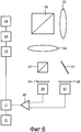
фиг.6 - принципиальная схема четвертой системы для дистанционной фотоплетизмографии.6 is a schematic diagram of a fourth system for remote photoplethysmography.
ОСУЩЕСТВЛЕНИЕ ИЗОБРЕТЕНИЯDETAILED DESCRIPTION OF THE INVENTION
Ниже приведено описание нескольких вариантов осуществления системы для дистанционной фотоплетизмографии. Фотоплетизмография является способом для определения характеристик некоторого периодического биологического явления, с использованием колебаний отражательной способности кожи. Кожу человека можно смоделировать как объект с, по меньшей мере, двумя слоями, одним из которых является эпидерма (тонкий поверхностный слой), а другим является дерма (более толстый слой под эпидермой). Приблизительно 5% падающих световых лучей отражается в эпидерме, что относится ко всем длинам волн и цветам кожи. Остальной свет рассеивается и поглощается внутри двух слоев кожи в рамках явления, известного под названием отражательная способность тела (описываемого дихроматической моделью отражения). Эпидерма действует подобно оптическому фильтру, в основном, путем поглощения света. В дерме свет как рассеивается, так и поглощается. Поглощение зависит от состава крови, так что поглощение чувствительно к изменениям кровотока. Оптические свойства дермы являются, в общем, одинаковыми для всех человеческих рас. Дерма содержит плотную сеть кровеносных сосудов, приблизительно, 10% от всей сосудистой сети взрослого человека. Упомянутые сосуды сжимаются соответственно кровотоку в теле. Следовательно, упомянутые сосуды изменяют структуры дермы, что влияет на отражательную способность слоев кожи. Следовательно, частоту сердечных сокращений можно определять по изменениям отражательной способности кожи.The following is a description of several embodiments of a system for remote photoplethysmography. Photoplethysmography is a method for characterizing a periodic biological phenomenon using fluctuations in the reflectivity of the skin. Human skin can be modeled as an object with at least two layers, one of which is the epidermis (thin surface layer), and the other is the dermis (a thicker layer under the epidermis). About 5% of the incident light rays are reflected in the epidermis, which applies to all wavelengths and skin colors. The rest of the light is scattered and absorbed within the two layers of the skin as part of a phenomenon known as the body reflectivity (described by the dichromatic reflection model). The epidermis acts like an optical filter, mainly by absorbing light. In the dermis, light is both scattered and absorbed. Absorption depends on the composition of the blood, so absorption is sensitive to changes in blood flow. The optical properties of the dermis are, in general, the same for all human races. The dermis contains a dense network of blood vessels, approximately 10% of the entire vasculature of an adult. The said vessels are compressed according to the blood flow in the body. Therefore, these vessels change the structure of the dermis, which affects the reflectivity of the layers of the skin. Therefore, heart rate can be determined by changes in the reflectivity of the skin.
Первая система для фотоплетизмографии (Фиг.1) содержит источник 1 света и оптическую систему для фокусировки света от источника света на зону открытой кожи живого объекта, например человека. Оптическая система в представленном варианте осуществления содержит светоделитель 2 и первую линзу 3.The first system for photoplethysmography (FIG. 1) comprises a light source 1 and an optical system for focusing light from a light source onto an open skin area of a living object, for example a person. The optical system in the embodiment shown comprises a beam splitter 2 and a first lens 3.
Отраженный свет собирается первой линзой 3, отражается светоделителем 2 и фокусируется второй линзой 4 на фотоприемник 5. В других вариантах осуществления оптическая система содержит дополнительные элементы, в том числе один или более элементов, таких как линзы, собирающие зеркала, светоделители, призмы и т.п.The reflected light is collected by the first lens 3, reflected by the beam splitter 2 and focused by the second lens 4 on the photodetector 5. In other embodiments, the optical system contains additional elements, including one or more elements, such as lenses, collecting mirrors, beam splitters, prisms, etc. P.
В представленном варианте осуществления свет проходит сквозь фильтр 6. Фильтр 6 является фильтром с зависимостью, по меньшей мере, от длин волн, выполненным с возможностью пропускания узкой полосы длин волн с центральной длиной волны, соответствующей максимуму в спектре поглощения воды. Полоса пропускания имеет ширину, зависящую от положения максимума в спектре поглощения воды. В общем, ширина является такой, что полная ширина на полувысоте максимума поглощения содержится в пределах полосы пропускания. Поэтому ширина может изменяться в пределах от 100 нм до 1 мкм. Максимумы в спектре поглощения воды наблюдаются на частотах, соответствующих длинам волн 514, 606, 660 и 739 нм в пределах видимого участка спектра. Дополнительные максимумы наблюдаются на длинах волн 836 и 970 нм, за пределами видимого участка спектра. Последние значения используют в вариантах осуществления, в которых уровни окружающего освещения являются низкими, и источник 1 света не должен излучать слишком много видимого света. Действительно, в некоторых упомянутых вариантах осуществления источник 1 света совсем не применяют, при этом сигнал, обеспечиваемый фотоприемником 5, обусловлен исключительно отраженным внешним электромагнитным излучением.In the present embodiment, the light passes through the filter 6. The filter 6 is a filter with at least wavelength dependence, configured to transmit a narrow wavelength band with a central wavelength corresponding to a maximum in the absorption spectrum of water. The passband has a width depending on the position of the maximum in the absorption spectrum of water. In general, the width is such that the full width at half maximum of the absorption maximum is contained within the passband. Therefore, the width can vary from 100 nm to 1 μm. The maxima in the absorption spectrum of water are observed at frequencies corresponding to wavelengths of 514, 606, 660 and 739 nm within the visible part of the spectrum. Additional maxima are observed at wavelengths of 836 and 970 nm, outside the visible region of the spectrum. The latter values are used in embodiments in which the ambient light levels are low and the light source 1 should not emit too much visible light. Indeed, in some of the aforementioned embodiments, the light source 1 is not used at all, while the signal provided by the photodetector 5 is due exclusively to reflected external electromagnetic radiation.
В вариантах осуществления, в которых применяют источник 1 света, фильтр 6 и источник 1 света могут быть поляризационно-зависимыми. При этом сигнал из фотоприемника 5 можно поддерживать, в общем, без изменений, обусловленных изменением уровней окружающего света.In embodiments where a light source 1 is used, the filter 6 and the light source 1 may be polarization dependent. In this case, the signal from the photodetector 5 can be maintained, in general, without changes due to changes in ambient light levels.
В представленном варианте осуществления сигнал из фотоприемника 5 поступает в устройство 7 для обработки данных, которое может быть программируемым универсальным вычислительным устройством или специализированным устройством.In the presented embodiment, the signal from the photodetector 5 enters the device 7 for processing data, which may be a programmable universal computing device or a specialized device.
Устройство 7 для обработки данных обеспечивает также управляющие сигналы для контроллера 8 и задающее устройство 9 для питания источника 1 света. В одном варианте осуществления оба упомянутых компонента 8, 9 встроены в одно устройство с устройством 7 для обработки данных.The data processing device 7 also provides control signals for the controller 8 and a driver 9 for supplying the light source 1. In one embodiment, both of these components 8, 9 are integrated in a single device with the device 7 for processing data.
Чтобы повысить отношение сигнала к шуму для сигнала из фотоприемника 5, можно применить гетеродинное детектирование. Свет, излучаемый источником 1 света, модулируют на некоторой частоте ν. Поэтому, фотоприемник 5 будет обеспечивать сигнал, который имеет такую же частоту, и сигнал на других частотах. Сигнал на других частотах можно подавлять.To increase the signal-to-noise ratio for the signal from the photodetector 5, heterodyne detection can be used. The light emitted by the light source 1 is modulated at a certain frequency ν. Therefore, the photodetector 5 will provide a signal that has the same frequency and a signal at other frequencies. The signal at other frequencies can be suppressed.
В одном варианте осуществления источник 1 света выполнен с возможностью излучения света с широким спектром. В другом варианте осуществления источник 1 света настроен на частоту, соответствующую максимуму в спектре поглощения воды. В частности, данная частота является, в общем, такой же, как частота, на которую настроен фильтр 6 с зависимостью от длин волн. Если частота соответствует длине волны в воздухе 836 нм или 970 нм, то видимое электромагнитное излучение не излучается.In one embodiment, the light source 1 is configured to emit wide-spectrum light. In another embodiment, the light source 1 is tuned to a frequency corresponding to a maximum in the absorption spectrum of water. In particular, this frequency is, in general, the same as the frequency at which the filter 6 is tuned depending on wavelengths. If the frequency corresponds to a wavelength in air of 836 nm or 970 nm, then visible electromagnetic radiation is not emitted.
Устройство 7 для обработки данных выполняет такие операции, как фильтрация и анализ. В частности, устройство 7 для обработки данных выполнено с возможностью определения частоты, на которой спектр сигнала или отфильтрованного сигнала имеет локальный максимум, по меньшей мере, в предварительно заданном диапазоне, соответствующем диапазону, в котором ожидается присутствие сигнала, соответствующего периодическому биологическому явлению. Тем самым можно определять частоту сердечных сокращений или частоту дыхания человека, от которого исходит захваченный свет. Информация, характеризующая найденное значение, выдается на устройстве 10 вывода.The device 7 for processing data performs operations such as filtering and analysis. In particular, the data processing apparatus 7 is configured to determine the frequency at which the spectrum of the signal or the filtered signal has a local maximum in at least a predetermined range corresponding to the range in which a signal corresponding to a periodic biological phenomenon is expected to be present. Thereby, it is possible to determine the heart rate or the respiratory rate of the person from whom the captured light emits. Information characterizing the found value is provided on the output device 10.
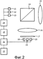
Возможно также использование света на частоте, соответствующей максимуму в спектре поглощения воды, в дополнение к свету на другой частоте. Данное решение представлено на фиг.2, где показана система, аналогичная системе на фиг.1, но с тремя источниками 11-13 света. В показанном варианте осуществления также применена оптическая система, содержащая светоделитель 14, первую линзу 15 для фокусировки света на открытую кожу живого объекта и захвата света, отраженного обратно от кожи, и вторую линзу 16 и фильтр 17 с зависимостью от поляризации.It is also possible to use light at a frequency corresponding to a maximum in the absorption spectrum of water, in addition to light at a different frequency. This solution is presented in figure 2, which shows a system similar to the system in figure 1, but with three light sources 11-13. In the shown embodiment, an optical system is also used comprising a
Каждый из трех фотоприемников 18-20 чувствителен к электромагнитному излучению в отличающемся диапазоне спектра, при этом, по меньшей мере, один из упомянутых диапазонов ограничен. Три диапазона могут частично перекрываться.Each of the three photodetectors 18-20 is sensitive to electromagnetic radiation in a different range of the spectrum, while at least one of these ranges is limited. Three ranges may partially overlap.
Один из трех фотоприемников 18-20 настроен на максимум в спектре поглощения воды. В одном примере другой из трех фотоприемников 18-20 настроен на диапазон длин волн в диапазоне от 500 нм до 600 нм, соответствующий зеленому свету. Следовательно, упомянутый датчик чувствителен к изменениям количества оксигемоглобина в коже. Третий из трех фотоприемников 18-20 может быть настроен на диапазон длин волн, который не чувствителен, в особенности к изменениям отражательной способности кожи. Действительно, третий из трех фотоприемников 18-20 может регистрировать просто изменения интенсивности света по всему спектру.One of the three photodetectors 18-20 is tuned to a maximum in the absorption spectrum of water. In one example, the other of the three photodetectors 18-20 is tuned to a wavelength range in the range of 500 nm to 600 nm corresponding to green light. Therefore, said sensor is sensitive to changes in the amount of oxyhemoglobin in the skin. The third of the three photodetectors 18-20 can be tuned to a wavelength range that is not sensitive, especially to changes in the reflectivity of the skin. Indeed, the third of three photodetectors 18-20 can simply record changes in light intensity over the entire spectrum.
Сигналы из фотоприемников 18-20 подаются в устройство 21 для обработки данных, которое обрабатывает упомянутые сигналы для обеспечения сигнала, который можно анализировать для определения характеристики составляющей, соответствующей периодическому биологическому явлению, например, значению частоты сердечных сокращений. С данной целью, можно определять корреляции между сигналом из датчика, настроенного на зеленый свет, и сигналом из датчика, настроенного на максимум в спектре поглощения воды, при том, что сигналы могут быть декоррелированы с сигналом из третьего датчика. Данный подход дает единственный сигнал, который содержит относительно чистую и мощную составляющую, вызванную изменениями отражательной способности кожи. Устройством 21 для обработки данных выполняется анализ сигнала, чтобы определить характеристику сигнала, например частоту (этап 47). Информация, представляющая характеристику, выдается на устройстве 22 вывода.The signals from the photodetectors 18-20 are supplied to a
Для дополнительного повышения отношения сигнала к шуму в представленном варианте осуществления используют настроенные источники 11-13 света, выполненные с возможностью излучения света в диапазонах спектра электромагнитного излучения, соответствующих диапазонам, на которые настроены фотоприемники 18-20. Для питания источников 11-13 света обеспечены задающее устройство 23 и контроллер 24. Контроллер 24 соединен с устройством 21 для обработки данных.To further increase the signal-to-noise ratio in the present embodiment, tuned light sources 11-13 are used, configured to emit light in the electromagnetic spectrum bands corresponding to the ranges that the photodetectors 18-20 are tuned to. A
В качестве варианта осуществления, показанного на Фиг.2, чтобы дополнительно повысить отношение сигнала к шуму, можно применить гетеродинное детектирование.As an embodiment, shown in FIG. 2, to further increase the signal-to-noise ratio, heterodyne detection can be applied.
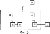
На фиг.3 представлена система для дистанционной фотоплетизмографии с использованием формирования изображения, при этом упомянутая система содержит систему 25 обработки данных и видеокамеру 26. Видеокамера 26 выполнена с возможностью представления последовательности изображений в интерфейс 27 системы 25 обработки данных. Система 25 обработки данных содержит устройство 28 обработки данных и основную память 29 для исполнения команд, содержащихся в программном обеспечении, хранящемся в устройстве 30 массовой памяти. Система 25 обработки данных дополнительно содержит интерфейс сопряжения с устройством 32 вывода, например, дисплеем.Figure 3 presents a system for remote photoplethysmography using image formation, while the said system comprises a
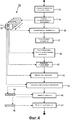
Первый вариант осуществления фотоплетизмографического способа, выполняемого системой 25 обработки данных, изображен на фиг.4.The first embodiment of the photoplethysmographic method performed by the
В данном варианте осуществления сначала выполняется этап 33 инициализации для определения подходящих параметров настройки видеокамеры 26. С данной целью система 25 обработки данных задает изменение, по меньшей мере, чего-то одного из частоты кадров, времени экспозиции, периода синхронизации для вывода пикселей (параметра настройки, определяющего частоту, с которой собираются значения пикселей) и коэффициента усиления камерного канала видеокамеры 26, пока собирается последовательность цифровых изображений. Определяется (пространственно) усредненная яркость, по меньшей мере, части каждого изображения последовательности, и определяется величина периодических флуктуаций усредненной яркости для каждого нового значения параметра настройки. Параметры настройки, для которых упомянутая величина в пределах, по меньшей мере, диапазона спектра, в частности диапазона до 100 Гц, является минимальной, выбираются для последующего использования при исполнении способа. Вместо определения пространственно усредненной яркости, по меньшей мере, части изображения, можно определять флуктуации яркости отдельных пикселей. Результат выбора параметров настройки видеокамеры 26 состоит в том, что из последовательности изображений, к которой применяются остальные этапы способа, в максимально возможной степени исключаются периодические флуктуации фонового освещения.In this embodiment, the
На следующем этапе 34 из видеокамеры 26 поступает последовательность 35 изображений.In the
В одном варианте осуществления видеокамера 26 снабжена единственным фильтром, настроенным на длину волны, соответствующую максимуму в спектре поглощения воды. В частности, как в вышеописанных вариантах осуществления, упомянутая длина волны может быть длиной волны, соответствующей частоте в пределах видимого участка спектра, например 514, 606, 660 или 739 нм. В другом варианте осуществления частота может находиться за пределами видимого диапазона спектра, например 836 нм или 970 нм, что вновь допускает применение обычных кремниевых матриц фотоприемников, которые чувствительны на упомянутом участке спектра.In one embodiment,
В альтернативных вариантах осуществления видеокамера 26 снабжена множеством фильтров, и, поэтому, каждое изображение в последовательности 35 соответствует множеству кадров изображения, каждый из которых содержит массив значений пикселей, характеризующих интенсивность света в отличающемся диапазоне спектра электромагнитного излучения. По меньшей мере, одна последовательность кадров изображений соответствует ограниченному диапазону с центральной частотой, соответствующей максимуму в спектре поглощения воды.In alternative embodiments, the
В дальнейшем изображения 35 обрабатываются (этап 36) для исключения непериодических сигналов фона. С данной целью формируется корректирующий сигнал, соответствующий меняющейся во времени усредненной яркости части или всех изображений 35. В изображенном варианте осуществления, затем, данные пикселей изображений 35 декоррелируются с корректирующим сигналом. Алгоритмы для подавления нелинейных кросс-корреляций, по существу, известны. На данном этапе 36 может выполняться дополнительная обработка изображений, например, для компенсации движения камеры.Subsequently, the
На двух следующих этапах 37, 38 выполняется способ сегментации изображений на, по меньшей мере, одной из последовательности 35 изображений. В частности, на данных этапах 37, 38 выполняется алгоритм для обнаружения части тела, в основном, лица человека. Подходящий алгоритм описан в работе Viola, P. and Jones, M.J., «Robust real-time object detection», Proc. Of IEEE Workshop on statistical and computational theories of vision, 13 July 2001. Известны другие подходящие алгоритмы, основанные на распознавании сегментов с некоторыми формами и/или цветами (например, цветами кожи), которые можно применять вместо или кроме упомянутого алгоритма, описанного в литературе.In the next two
По меньшей мере, один выявленный отчетливый сегмент 39, соответствующий части тела требуемого типа, сопровождается (этап 40) по всей последовательности 35 изображений. То есть, устанавливается место сегмента 39, а именно, определяется его местоположение, путем сравнения изображений в последовательности 35 для количественного определения перемещения части тела в пределах изображений 35. Подходящий алгоритм сопровождения описан, например, в работе De Haan et al., «True-motion estimation with 3-D recursive search block matching», IEEE Transactions on circuits and systems for video technology, 1 (5), October 1993, pp. 368-379.At least one distinct
В дальнейшем для каждого выбранного и сопровождаемого сегмента 39 выбирается зона 41 измерения в пределах сегмента 39 изображения (этап 42). Данный этап 42 включает в себя пространственный анализ данных пикселей множества частей изображения, чтобы определить набор прилегающих частей, имеющих аналогичные характеристики, при этом каждая упомянутая часть является по размеру, по меньшей мере, одной точкой изображения. Упомянутые части выбирают для формирования зоны 41 измерения. Положение зоны 41 измерения определяется относительно сопровождаемого сегмента 39, в котором упомянутая зона содержится, так что она сопровождается аналогичным образом.Subsequently, for each selected and followed
Следующий этап 43 содержит формирование сигнала 44 яркости, каждое значение которого является комбинацией значений пикселей из зоны 41 измерения в одном конкретном из последовательности 35 изображений.The
Когда изображения содержат кадры изображений, соответствующие разным диапазонам в спектре электромагнитного излучения, данный этап 43 может содержать множество этапов (не показанных подробно), на которых формируется отдельный сигнал для каждой последовательности кадров изображений. Затем упомянутые сигналы обрабатываются для обеспечения единственного сигнала 44. В частности, когда одна последовательность кадров изображений соответствует частотному диапазону, соответствующему максимуму в спектре поглощения воды, а другая последовательность соответствует зеленому свету, можно поддерживать только общие составляющие сигнала. Для подавления шума можно использовать последовательность, соответствующую общему уровню интенсивности или поддиапазону, не чувствительному к изменениям, обусловленным пульсацией кровотока.When the images contain image frames corresponding to different ranges in the spectrum of electromagnetic radiation, this
Затем (на этапе 45) сигнал 44 яркости центрируется относительно своего среднего значения, что дает окончательный сигнал 46, характеризующий, по меньшей мере, изменения значения, основанного на множестве значений пикселей из каждого изображения из последовательности 35 изображений. В альтернативных вариантах осуществления применяют альтернативный метод выделения изменений порядка 1 % от динамического диапазона сигнала 44 яркости, например операцию фильтрации, включающую в себя этап дифференцирования.Then (at step 45), the
Наконец (на этапе 47), выделяется характеристика контролируемого периодического биологического явления. Данной характеристикой может быть, например, частота сердечных сокращений исследуемого человека. При использовании, например, быстрого преобразования Фурье, можно определить локальный максимум в спектре сигнала 46.Finally (at step 47), a characteristic of a controlled periodic biological phenomenon is highlighted. This characteristic may be, for example, the heart rate of the person under study. When using, for example, the fast Fourier transform, it is possible to determine the local maximum in the
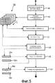
На фиг.5 представлен способ, альтернативный способу, представленному на фиг.4. Данный вариант осуществления позволяет также формировать, например, карты фаз.Figure 5 presents a method alternative to the method presented in figure 4. This embodiment also makes it possible to form, for example, phase maps.
Способ, представленный на фиг.5, также начинается с этапа 48 инициализации для определения подходящих параметров настройки видеокамеры 26. Система 25 обработки данных задает изменение, по меньшей мере, чего-то одного из частоты кадров, времени экспозиции, периода синхронизации для вывода пикселей (параметра настройки, определяющего частоту, с которой собираются значения пикселей) и коэффициента усиления камерного канала видеокамеры 26, пока собирается последовательность цифровых изображений. Определяется (пространственно) усредненная яркость, по меньшей мере, части каждого изображения последовательности, и определяется величина периодических флуктуаций усредненной яркости для каждого нового значения параметра настройки. Параметры настройки, для которых упомянутая величина в пределах, по меньшей мере, диапазона спектра, в частности диапазона до 100 Гц, является минимальной, выбираются для последующего использования при исполнении способа. Вместо определения пространственно усредненной яркости, по меньшей мере, части изображения, можно определять флуктуации яркости отдельных пикселей.The method shown in FIG. 5 also starts with
Затем (на этапе 49) получают последовательность 50 изображений. Как в варианте осуществления, показанном на Фиг.4, упомянутая последовательность 50 может быть составлена из множества последовательностей кадров изображений, соответствующих, каждый, отличающемуся участку спектра электромагнитного излучения (т.е. отличающемуся цветовому каналу, если используют только видимый спектр).Then (at step 49), a sequence of 50 images is obtained. As in the embodiment shown in FIG. 4, said
Изображения 50 обрабатываются для исключения непериодических сигналов фона, с использованием корректирующего сигнала, соответствующего меняющейся во времени усредненной яркости части или всех изображений 50 (этап 51). Данный этап аналогичен соответствующему этапу 36 в способе, представленном на фиг.4.
Затем (на этапе 52) на изображения 50 накладывается сетка, при этом упомянутая сетка разбивает каждое изображение на множество зон измерения или, по меньшей мере, потенциальные зоны измерения. Каждая зона измерения содержит множество значений пикселей.Then (at step 52), a grid is superimposed on the
Сигналы 53a-n выделяют (на этапе 54) для, по меньшей мере, одной, но, в более общем случае, множества зон измерения, заданных сеткой. Данный этап 54 включает в себя формирование, из значений пикселей из зоны измерения, одного комбинированного значения таким образом, что каждое значение сигнала 53 основано на значениях пикселей только из одного из изображений 50. Следовательно, результатом является набор изменяющихся во времени сигналов 53a-n, характеризующих яркость соответствующей зоны измерения. В одном варианте осуществления значения пикселей объединяют в комбинацию усреднением. В другом варианте осуществления значения пикселей объединяют в комбинацию получением среднего значения. Формирование комбинации исключает случайный шум и, тем самым, дает сигнал с более мощной составляющей, соответствующей периодическому биологическому явлению.
Когда последовательность 50 изображений состоит из множества последовательностей кадров изображений, соответствующих, каждый, отличающемуся диапазону спектра электромагнитного излучения, значения пикселей из соответствующих зон измерения в каждом из кадров изображения, составляющих изображение, комбинируют. Комбинацию формируют так, чтобы исключить сигналы фона или усилить составляющие, соответствующие биологическим сигналам. Таким образом, когда кадры изображения содержат значения пикселей, соответствующие значениям интенсивности в диапазоне спектра с центром на максимуме в спектре поглощения воды, и значения пикселей, соответствующие значениям интенсивности в диапазоне спектра в пределах диапазона от 500 нм до 600 нм, то этап 54 формирования комбинации может содержать этап кросс-корреляции.When the
Далее (на этапе 55) сигналы 53a-n центрируются относительно их средних значений, что дает дополнительный набор сигналов 56a-n, характеризующих, по меньшей мере, изменения значения, основанного на значениях пикселей соответствующих зон измерения. Вместо центрирования сигналов 53a-n относительно их среднего значения можно применить другую операцию, подходящую для выделения изменений порядка 1% от динамического диапазона сигналов 53a-n, например дифференцирование или аналогичную операцию фильтрации.Next (at step 55), the
Наконец (этап 57), определяют характеристику, по меньшей мере, составляющей, по меньшей мере, одного из окончательных сигналов 56a-n. Например, чтобы установить значение частоты сердечных сокращений человека, представляемого последовательностью 50 изображений, можно определить частоту локального максимума в спектре сигналов 56a-n. В другом варианте осуществления, в котором используют все зоны измерения, создается карта фаз. В другом варианте осуществления применяют кластеризацию сигналов 56a-n или значений, полученных из окончательных сигналов 56a-n, чтобы установить согласованное значение, характеризующее биологическое явление.Finally (step 57), a characteristic of at least a component of at least one of the
Совершенно другой вариант осуществления системы для фотоплетизмографии изображен на фиг.6. Данная система получает два сигнала, один из которых используют для исключения артефактов движения и освещения из другого сигнала.A completely different embodiment of the photoplethysmography system is shown in FIG. 6. This system receives two signals, one of which is used to exclude artifacts of movement and lighting from another signal.
В представленном варианте осуществления система содержит источник 58 света. Источник 58 света может излучать спектр с двумя максимумами, источник может излучать непрерывный спектр, или источник может излучать свет с обеими характеристиками. В альтернативном варианте осуществления источник 58 света не применяют. Вместо него используют окружающий (белый) свет.In the present embodiment, the system comprises a
Система, представленная на фиг.6, содержит также оптическую систему, содержащую первый светоделитель 59, первую линзу 60 для фокусировки света из источника 58 света на открытую кожу живого объекта и захвата света, отраженного обратно от кожи, и вторую линзу 61.The system of FIG. 6 also comprises an optical system comprising a
Свет, собранный второй линзой 61, пропускается на второй светоделитель 62. Второй светоделитель 62 может быть светоделителем с зависимостью от поляризации или с зависимостью от длин волн. Данный светоделитель делит свет, содержащий, по меньшей мере, две длины волны на раздельные пучки.The light collected by the
Первый пучок направляется на первый датчик 63 сквозь первый фильтр 64. Первый фильтр 64 настроен на максимум в спектре поглощения воды. В одном варианте осуществления максимум находится в диапазоне, соответствующем диапазону длин волн больше 750 нм. Кроме того, диапазон может заканчиваться на длине волны меньше 1100 нм.The first beam is directed to the
Второй пучок направляется зеркалом 65 и сквозь второй фильтр 66 на второй датчик 67. Второй фильтр 66 выполнен с возможностью пропускания света в ином диапазоне длин волн, чем первый фильтр 64, и, поэтому, второй датчик 67 выполнен с возможностью захвата света от живого объекта в ином диапазоне длин волн, чем первый датчик 63.The second beam is guided by a
Следует заметить, что другой диапазон длин волн может перекрывать длину волны, на которую настроен первый фильтр 64. В частности, второй фильтр 66 может отсутствовать, так что второй датчик 67 обеспечивает сигнал, характеризующий уровни окружающего света.It should be noted that a different wavelength range may overlap the wavelength to which the
Однако, в общем, другой диапазон длин волн будет разделен с полосой пропускания первого фильтра 64.However, in general, another wavelength range will be shared with the passband of the
Сигналы из датчиков 63, 67 подаются в устройство 68 для вычитания сигналов (например, операционный усилитель), чтобы сигнал из второго датчика 67 вычитался из сигнала из первого датчика 63.The signals from the
Результат подается в устройство 71 для обработки данных, которое обрабатывает, например анализирует, разностный сигнал для обеспечения выходной характеристики составляющей, соответствующей периодическому биологическому явлению, например, значения частоты сердечных сокращений. Анализ сигнала устройством 21 для обработки данных может включать в себя определение характеристики сигнала, например частоты. Информация, представляющая характеристику, выдается на устройство 72 вывода.The result is supplied to a
Для дополнительного повышения отношения сигнала к шуму можно применить гетеродинное детектирование, при этом обеспечены задающее устройство 69 и контроллер 70 для питания источника 58 света.To further increase the signal-to-noise ratio, heterodyne detection can be applied, while a
Чтобы сигнал, вычитаемый из сигнала из первого датчика 63, гарантированно устранял составляющие, обусловленные движением живого объекта и/или изменениями освещенности в среде, окружающей живой объект, перед применением системы, показанной на фиг.6, на живом объекте, выполняют этап калибровки.In order to ensure that the signal subtracted from the signal from the
На этапе калибровки обеспечивают калибровочную поверхность, на которую фокусируют свет из источника света 58. Данная калибровочная поверхность представляет собой, в одном варианте осуществления, белый рассеиватель с известными характеристиками рассеяния (например, длиной волны, углом к оптической оси первой линзы 60 и поляризацией). Затем чувствительность и коэффициент усиления двух датчиков 63, 67 настраивают таким образом, чтобы сигналы, выдаваемые в устройство 68 для вычитания сигналов, были идентичными по фазе и амплитуде. В одном варианте осуществления данный этап калибровки выполняют для разных комбинаций углов, длин волн и поляризаций. Калибровку не обязательно выполнять на месте эксплуатации, а можно выполнять при изготовлении системы, показанной на фиг.6. В одном варианте осуществления устройство 71 для обработки данных применяют для вызова верных параметров настройки.At the calibration stage, a calibration surface is provided on which the light from the
Следует отметить, что вышеприведенные варианты осуществления поясняют, а не ограничивают изобретение, и что специалисты в данной области техники смогут спроектировать множество альтернативных вариантов осуществления, не выходящих за пределы объема прилагаемой формулы изобретения. В формуле изобретения никакие позиции, помещенные в скобки, нельзя истолковывать как ограничивающие пункт формулы изобретения. Выражение «содержащий» не исключает присутствия элементов или этапов, отличающихся от элементов или этапов, перечисленных в пункте формулы изобретения. Использование единственного числа в отношении элементов не исключает присутствия множества упомянутых элементов. Очевидное обстоятельство, что некоторые признаки упомянуты во взаимно отличающихся зависимых пунктах формулы изобретения, не означает, что, в подходящих случаях, нельзя использовать сочетание упомянутых признаков.It should be noted that the above embodiments illustrate, but not limit, the invention, and that those skilled in the art will be able to design many alternative embodiments without departing from the scope of the attached claims. In the claims, no items in parentheses may be construed as limiting the claims. The expression “comprising” does not exclude the presence of elements or steps other than the elements or steps listed in a claim. The use of the singular with respect to elements does not exclude the presence of a plurality of said elements. The obvious circumstance that some features are mentioned in mutually different dependent dependent claims does not mean that, in suitable cases, a combination of the mentioned features cannot be used.
В модификации вариантов осуществления, представленных на фиг.1-3, устройство 7, 21 для обработки данных или система 25 обработки данных обеспечивает выходной сигнал, имеющий частоту, соответствующую частоте представляющего интерес периодического биологического явления, которую можно использовать для стробирования дополнительного устройства (не показанного), например устройства визуализации.In a modification of the embodiments of FIGS. 1-3, a
В модификации варианта осуществления, представленного на Фиг.3, система 25 обработки данных содержит интерфейс сопряжения с, по меньшей мере, одним источником света. Один из источников света может быть настроен на максимум в спектре поглощения воды, в частности на одно из значений длин волн на ближнем инфракрасном участке электромагнитного спектра.In a modification of the embodiment of FIG. 3, the
Claims (10)
обрабатывают сигнал (46; 56), основанный на по меньшей мере одном сигнале (35; 50) из по меньшей мере одного датчика (5; 18-20; 26; 63), выполненного с возможностью захвата света от живого объекта, чтобы выделять информацию о характеристике периодического биологического явления,
при этом по меньшей мере один из сигналов (35; 50) из по меньшей мере одного датчика (5; 18-20; 26; 63) получают с использованием по меньшей мере одного из источника (1; 11-13) света и фильтра (6; 17; 64), установленного перед по меньшей мере одним датчиком (5; 18-20; 26; 63), настроенным на максимум в спектре поглощения воды.1. The method of remote photoplethysmography, containing stages in which:
process a signal (46; 56) based on at least one signal (35; 50) from at least one sensor (5; 18-20; 26; 63), configured to capture light from a living object to extract information about the characteristic of a periodic biological phenomenon,
wherein at least one of the signals (35; 50) from at least one sensor (5; 18-20; 26; 63) is obtained using at least one of the light source (1; 11-13) and a filter ( 6; 17; 64) installed in front of at least one sensor (5; 18-20; 26; 63), tuned to a maximum in the absorption spectrum of water.
по меньшей мере, один датчик (5; 18-20; 26; 63) для захвата света от живого объекта;
систему (7; 21; 25; 71) обработки сигналов, выполненную с возможностью обработки сигнала (46; 56), основанного на по меньшей мере одном сигнале (35; 50) из по меньшей мере одного датчика (5; 18-20; 26; 63), чтобы выделять информацию о характеристике периодического биологического явления; и
по меньшей мере, один из источника (1; 11-13) света и фильтра (6; 17; 64), установленный перед по меньшей мере одним из датчиков (5; 18-20; 26; 63), настроенным на максимум в спектре поглощения воды.9. A system for performing remote photoplethysmography, comprising:
at least one sensor (5; 18-20; 26; 63) for capturing light from a living object;
a signal processing system (7; 21; 25; 71;) configured to process a signal (46; 56) based on at least one signal (35; 50) from at least one sensor (5; 18-20; 26 ; 63) to highlight information about the characteristic of a periodic biological phenomenon; and
at least one of a light source (1; 11-13) and a filter (6; 17; 64) installed in front of at least one of the sensors (5; 18-20; 26; 63) configured to a maximum in the spectrum water absorption.
Applications Claiming Priority (3)
| Application Number | Priority Date | Filing Date | Title |
|---|---|---|---|
| EP09172345 | 2009-10-06 | ||
| EP09172345.2 | 2009-10-06 | ||
| PCT/IB2010/054462 WO2011042851A1 (en) | 2009-10-06 | 2010-10-04 | Method and system for carrying out photoplethysmography |
Publications (2)
| Publication Number | Publication Date |
|---|---|
| RU2012118645A RU2012118645A (en) | 2013-11-20 |
| RU2550427C2 true RU2550427C2 (en) | 2015-05-10 |
Family
ID=43127729
Family Applications (1)
| Application Number | Title | Priority Date | Filing Date |
|---|---|---|---|
| RU2012118645/14A RU2550427C2 (en) | 2009-10-06 | 2010-10-04 | Method and system for performing photoplethysmography |
Country Status (7)
| Country | Link |
|---|---|
| US (1) | US10271746B2 (en) |
| EP (1) | EP2485639B1 (en) |
| JP (1) | JP6148009B2 (en) |
| CN (1) | CN102647941B (en) |
| BR (1) | BR112012007924A2 (en) |
| RU (1) | RU2550427C2 (en) |
| WO (1) | WO2011042851A1 (en) |
Families Citing this family (40)
| Publication number | Priority date | Publication date | Assignee | Title |
|---|---|---|---|---|
| US8577431B2 (en) | 2008-07-03 | 2013-11-05 | Cercacor Laboratories, Inc. | Noise shielding for a noninvasive device |
| US8630691B2 (en) | 2008-08-04 | 2014-01-14 | Cercacor Laboratories, Inc. | Multi-stream sensor front ends for noninvasive measurement of blood constituents |
| MX347895B (en) | 2011-08-01 | 2017-05-18 | Koninklijke Philips Nv | Device and method for obtaining and processing measurement readings of a living being. |
| GB201114406D0 (en) | 2011-08-22 | 2011-10-05 | Isis Innovation | Remote monitoring of vital signs |
| JP5773816B2 (en) * | 2011-09-12 | 2015-09-02 | キヤノン株式会社 | Imaging device |
| BR112015008744A2 (en) * | 2012-10-23 | 2017-07-04 | Koninklijke Philips Nv | device for obtaining vital sign information from a living being; and method of obtaining vital sign information from a living being |
| US9955900B2 (en) | 2012-10-31 | 2018-05-01 | Quaerimus, Inc. | System and method for continuous monitoring of a human foot |
| US9901298B2 (en) * | 2012-11-01 | 2018-02-27 | Quaerimus Medical Incorporated | System and method for prevention of diabetic foot ulcers using total internal reflection imaging |
| JP6268182B2 (en) * | 2012-11-02 | 2018-01-24 | コーニンクレッカ フィリップス エヌ ヴェKoninklijke Philips N.V. | Apparatus and method for extracting physiological information |
| JP6270287B2 (en) * | 2012-11-23 | 2018-01-31 | コーニンクレッカ フィリップス エヌ ヴェKoninklijke Philips N.V. | Device and method for extracting physiological information |
| CN102973259A (en) * | 2012-11-30 | 2013-03-20 | 刘庆国 | Photoelectric heart rate measuring circuit |
| EP2762066A1 (en) * | 2013-02-05 | 2014-08-06 | Koninklijke Philips N.V. | System and method for determining vital sign information of a subject |
| CN105142501B (en) * | 2013-03-06 | 2019-02-01 | 皇家飞利浦有限公司 | System and method for determining vital sign information |
| US10238292B2 (en) | 2013-03-15 | 2019-03-26 | Hill-Rom Services, Inc. | Measuring multiple physiological parameters through blind signal processing of video parameters |
| US20140330132A1 (en) * | 2013-05-02 | 2014-11-06 | Aza Raskin | Physiological characteristic detection based on reflected components of light |
| CN104207761B (en) * | 2013-06-03 | 2016-05-25 | 飞比特公司 | Heart rate data is collected |
| JP6467417B2 (en) | 2013-08-06 | 2019-02-13 | コーニンクレッカ フィリップス エヌ ヴェKoninklijke Philips N.V. | System and method for extracting physiological information from remotely detected electromagnetic radiation |
| WO2015030832A1 (en) * | 2013-08-31 | 2015-03-05 | Pandata Research Llc | Integrated optoelectronic module for physiological measurements and methods of use of the module |
| US9928607B2 (en) * | 2013-10-17 | 2018-03-27 | Koninklijke Philips N.V. | Device and method for obtaining a vital signal of a subject |
| WO2015150096A1 (en) | 2014-03-31 | 2015-10-08 | Koninklijke Philips N.V. | Device, system and method for determining vital signs of a subject |
| US20150327800A1 (en) * | 2014-05-16 | 2015-11-19 | Mediatek Inc. | Apparatus and method for obtaining vital sign of subject |
| WO2016003268A2 (en) * | 2014-06-30 | 2016-01-07 | Scint B.V. | Method and device for measuring a health status and physiological parameters of an user at rest and under movement |
| TWI558375B (en) * | 2014-09-18 | 2016-11-21 | 義明科技股份有限公司 | Ppg signal processing device and method thereof |
| US9770213B2 (en) * | 2014-10-30 | 2017-09-26 | Koninklijke Philips N.V. | Device, system and method for extracting physiological information |
| CA2967569C (en) * | 2014-11-13 | 2024-01-16 | Huibert Visser | Spatially resolved gas detection |
| CN104622444B (en) * | 2015-01-30 | 2017-03-22 | 中国科学院电子学研究所 | Wrist monitoring system with multiple photoelectric sensor modules |
| DE102015104312A1 (en) * | 2015-03-23 | 2016-09-29 | Osram Opto Semiconductors Gmbh | Sensor for detecting a biometric function |
| EP3087916B1 (en) * | 2015-04-28 | 2023-09-20 | Nokia Technologies Oy | Physiological measurement sensor |
| US10448871B2 (en) | 2015-07-02 | 2019-10-22 | Masimo Corporation | Advanced pulse oximetry sensor |
| US10244987B2 (en) * | 2015-08-13 | 2019-04-02 | Pixart Imaging Inc. | Physiological detection system with adjustable signal source and operating method thereof |
| CN106551690A (en) * | 2015-09-30 | 2017-04-05 | 齐心 | A kind of vital sign measurement device and method |
| US9717424B2 (en) | 2015-10-19 | 2017-08-01 | Garmin Switzerland Gmbh | System and method for generating a PPG signal |
| US10335045B2 (en) | 2016-06-24 | 2019-07-02 | Universita Degli Studi Di Trento | Self-adaptive matrix completion for heart rate estimation from face videos under realistic conditions |
| US11076771B2 (en) | 2016-09-22 | 2021-08-03 | Apple Inc. | Systems and methods for determining physiological signals using ambient light |
| CN106889980A (en) * | 2017-01-13 | 2017-06-27 | 佳禾智能科技股份有限公司 | Self adaptation switching heart rate detection method, device and wearable heartbeat detection device based on spectrogram |
| US10939833B2 (en) * | 2017-05-01 | 2021-03-09 | Samsung Electronics Company, Ltd. | Determining artery location using camera-based sensing |
| EP3501380A1 (en) * | 2017-12-22 | 2019-06-26 | Nokia Technologies Oy | Detector arrangement suited for optical sensors |
| EP3545821A1 (en) * | 2018-03-27 | 2019-10-02 | Koninklijke Philips N.V. | Device, system and method for extracting physiological information indicative of at least one vital sign of a subject |
| US20240065566A1 (en) * | 2022-08-23 | 2024-02-29 | Samsung Electronics Co., Ltd. | Polarized photoplethysmography (ppg) biosensors, arrays and systems |
| US20240065567A1 (en) * | 2022-08-23 | 2024-02-29 | Samsung Electronics Co., Ltd. | Methods and systems for polarized photoplethysmography (ppg) and biosignal analysis |
Citations (4)
| Publication number | Priority date | Publication date | Assignee | Title |
|---|---|---|---|---|
| RU2032376C1 (en) * | 1991-06-28 | 1995-04-10 | Московский областной научно-исследовательский клинический институт | Method for determining status of biological tissue and photoplethysmograph for carrying out same |
| WO2005051190A1 (en) * | 2003-11-21 | 2005-06-09 | Kings College Hospital Nhs Trust | Blood flow monitoring equipment |
| EP1764034A2 (en) * | 2005-09-20 | 2007-03-21 | Pacesetter, Inc. | Implantable self-calibrating optical sensors |
| EP2087837A1 (en) * | 2006-11-27 | 2009-08-12 | Pioneer Corporation | Emission sensor device and bioinformation detecting method |
Family Cites Families (31)
| Publication number | Priority date | Publication date | Assignee | Title |
|---|---|---|---|---|
| US4958638A (en) | 1988-06-30 | 1990-09-25 | Georgia Tech Research Corporation | Non-contact vital signs monitor |
| US5203328A (en) * | 1991-07-17 | 1993-04-20 | Georgia Tech Research Corporation | Apparatus and methods for quantitatively measuring molecular changes in the ocular lens |
| EP0527703B1 (en) * | 1991-08-12 | 1995-06-28 | AVL Medical Instruments AG | Device for measuring at least one gaseous concentration level in particular the oxygen concentration level in blood |
| US5699797A (en) * | 1992-10-05 | 1997-12-23 | Dynamics Imaging, Inc. | Method of investigation of microcirculation functional dynamics of physiological liquids in skin and apparatus for its realization |
| EP0957750A1 (en) * | 1995-10-23 | 1999-11-24 | Cytometrics, Inc. | Method and apparatus for reflected imaging analysis |
| US5995856A (en) | 1995-11-22 | 1999-11-30 | Nellcor, Incorporated | Non-contact optical monitoring of physiological parameters |
| JP2001526073A (en) * | 1997-12-22 | 2001-12-18 | ビー・ティー・ジー・インターナショナル・リミテッド | Artifact reduction in optical volume fluctuation recording |
| JP3547968B2 (en) | 1998-01-19 | 2004-07-28 | 株式会社日本自動車部品総合研究所 | Pulse waveform detector |
| WO2000044274A2 (en) | 1999-01-29 | 2000-08-03 | Pougatchev Vadim I | Personal physiological monitor |
| US6442411B1 (en) | 1999-04-21 | 2002-08-27 | Optix, Lp | Method for improving calibration of an instrument for non-invasively measuring constituents in arterial blood |
| US7904139B2 (en) * | 1999-08-26 | 2011-03-08 | Non-Invasive Technology Inc. | Optical examination of biological tissue using non-contact irradiation and detection |
| US6915154B1 (en) * | 1999-09-24 | 2005-07-05 | National Research Council Of Canada | Method and apparatus for performing intra-operative angiography |
| US7171251B2 (en) | 2000-02-01 | 2007-01-30 | Spo Medical Equipment Ltd. | Physiological stress detector device and system |
| JP2005095193A (en) * | 2000-04-05 | 2005-04-14 | Matsushita Electric Ind Co Ltd | Biological information measuring method and measuring device |
| DE10051943B4 (en) * | 2000-10-19 | 2015-01-15 | Fresenius Medical Care Deutschland Gmbh | Method and device for pulse wave transit time determination and extracorporeal blood treatment device with such a device |
| US6591122B2 (en) | 2001-03-16 | 2003-07-08 | Nellcor Puritan Bennett Incorporated | Device and method for monitoring body fluid and electrolyte disorders |
| US8135448B2 (en) | 2001-03-16 | 2012-03-13 | Nellcor Puritan Bennett Llc | Systems and methods to assess one or more body fluid metrics |
| US7024235B2 (en) | 2002-06-20 | 2006-04-04 | University Of Florida Research Foundation, Inc. | Specially configured nasal pulse oximeter/photoplethysmography probes, and combined nasal probe/cannula, selectively with sampler for capnography, and covering sleeves for same |
| US7738935B1 (en) * | 2002-07-09 | 2010-06-15 | Pacesetter, Inc. | Methods and devices for reduction of motion-induced noise in pulse oximetry |
| US7190985B2 (en) * | 2004-02-25 | 2007-03-13 | Nellcor Puritan Bennett Inc. | Oximeter ambient light cancellation |
| US7277741B2 (en) | 2004-03-09 | 2007-10-02 | Nellcor Puritan Bennett Incorporated | Pulse oximetry motion artifact rejection using near infrared absorption by water |
| WO2006034211A2 (en) | 2004-09-21 | 2006-03-30 | Digital Signal Corporation | System and method for remotely monitoring physiological functions |
| GB0607270D0 (en) * | 2006-04-11 | 2006-05-17 | Univ Nottingham | The pulsing blood supply |
| WO2007144880A2 (en) * | 2006-06-13 | 2007-12-21 | Elfi-Tech Ltd. | System and method for measurement of biological parameters of a subject |
| US8360986B2 (en) | 2006-06-30 | 2013-01-29 | University Of Louisville Research Foundation, Inc. | Non-contact and passive measurement of arterial pulse through thermal IR imaging, and analysis of thermal IR imagery |
| US8189887B2 (en) * | 2006-10-02 | 2012-05-29 | Johnson & Johnson Consumer Companies, Inc. | Imaging standard apparatus and method |
| US20080294012A1 (en) * | 2007-05-22 | 2008-11-27 | Kurtz Andrew F | Monitoring physiological conditions |
| CA2750760C (en) * | 2008-01-25 | 2019-11-19 | Novadaq Technologies Inc. | Method for evaluating blush in myocardial tissue |
| ES2385602T3 (en) | 2008-02-07 | 2012-07-27 | Pulsion Medical Systems Ag | Apparatus and procedure to determine a physiological parameter |
| US20090247853A1 (en) | 2008-03-31 | 2009-10-01 | Nellcor Puritan Bennett Llc | Non-Invasive Total Hemoglobin Measurement by Spectral Optical Coherence Tomography |
| US20110251493A1 (en) * | 2010-03-22 | 2011-10-13 | Massachusetts Institute Of Technology | Method and system for measurement of physiological parameters |
-
2010
- 2010-10-04 WO PCT/IB2010/054462 patent/WO2011042851A1/en active Application Filing
- 2010-10-04 EP EP10768581.0A patent/EP2485639B1/en active Active
- 2010-10-04 RU RU2012118645/14A patent/RU2550427C2/en active
- 2010-10-04 CN CN201080055343.8A patent/CN102647941B/en active Active
- 2010-10-04 BR BR112012007924-7A patent/BR112012007924A2/en not_active Application Discontinuation
- 2010-10-04 JP JP2012532700A patent/JP6148009B2/en active Active
- 2010-10-04 US US13/500,336 patent/US10271746B2/en active Active
Patent Citations (4)
| Publication number | Priority date | Publication date | Assignee | Title |
|---|---|---|---|---|
| RU2032376C1 (en) * | 1991-06-28 | 1995-04-10 | Московский областной научно-исследовательский клинический институт | Method for determining status of biological tissue and photoplethysmograph for carrying out same |
| WO2005051190A1 (en) * | 2003-11-21 | 2005-06-09 | Kings College Hospital Nhs Trust | Blood flow monitoring equipment |
| EP1764034A2 (en) * | 2005-09-20 | 2007-03-21 | Pacesetter, Inc. | Implantable self-calibrating optical sensors |
| EP2087837A1 (en) * | 2006-11-27 | 2009-08-12 | Pioneer Corporation | Emission sensor device and bioinformation detecting method |
Also Published As
| Publication number | Publication date |
|---|---|
| EP2485639B1 (en) | 2019-08-14 |
| CN102647941B (en) | 2015-11-25 |
| JP6148009B2 (en) | 2017-06-14 |
| BR112012007924A2 (en) | 2020-08-18 |
| EP2485639A1 (en) | 2012-08-15 |
| WO2011042851A1 (en) | 2011-04-14 |
| JP2013506525A (en) | 2013-02-28 |
| CN102647941A (en) | 2012-08-22 |
| US10271746B2 (en) | 2019-04-30 |
| US20120197137A1 (en) | 2012-08-02 |
| RU2012118645A (en) | 2013-11-20 |
Similar Documents
| Publication | Publication Date | Title |
|---|---|---|
| RU2550427C2 (en) | Method and system for performing photoplethysmography | |
| US10169862B2 (en) | Methods and systems for laser speckle imaging of tissue using a color image sensor | |
| EP2404283B1 (en) | Processing images of at least one living being | |
| JP5856960B2 (en) | Method and system for obtaining a first signal for analysis to characterize at least one periodic component of the first signal | |
| US8542878B2 (en) | Method of controlling a function of a device and system for detecting the presence of a living being | |
| US9741113B2 (en) | Image processing device, imaging device, image processing method, and computer-readable recording medium | |
| JP7229676B2 (en) | Biological information detection device and biological information detection method | |
| JP2009250658A (en) | Signal processor, signal processing method and program | |
| US10477119B2 (en) | Imaging device | |
| JP6585623B2 (en) | Biological information measuring device, biological information measuring method, and biological information measuring program | |
| JPH11299760A (en) | Brain activity measuring device | |
| RU2602505C1 (en) | Method of generating television image in turbid media with scattering prevailing over absorption (versions) and device therefor |