RU2509520C2 - Vacuum cleaner robot containing sensory handle - Google Patents
Vacuum cleaner robot containing sensory handle Download PDFInfo
- Publication number
- RU2509520C2 RU2509520C2 RU2011122468/12A RU2011122468A RU2509520C2 RU 2509520 C2 RU2509520 C2 RU 2509520C2 RU 2011122468/12 A RU2011122468/12 A RU 2011122468/12A RU 2011122468 A RU2011122468 A RU 2011122468A RU 2509520 C2 RU2509520 C2 RU 2509520C2
- Authority
- RU
- Russia
- Prior art keywords
- handle
- vacuum cleaner
- cleaner
- robot
- vacuum
- Prior art date
Links
Images


Classifications
-
- A—HUMAN NECESSITIES
- A47—FURNITURE; DOMESTIC ARTICLES OR APPLIANCES; COFFEE MILLS; SPICE MILLS; SUCTION CLEANERS IN GENERAL
- A47L—DOMESTIC WASHING OR CLEANING; SUCTION CLEANERS IN GENERAL
- A47L9/00—Details or accessories of suction cleaners, e.g. mechanical means for controlling the suction or for effecting pulsating action; Storing devices specially adapted to suction cleaners or parts thereof; Carrying-vehicles specially adapted for suction cleaners
- A47L9/009—Carrying-vehicles; Arrangements of trollies or wheels; Means for avoiding mechanical obstacles
-
- A—HUMAN NECESSITIES
- A47—FURNITURE; DOMESTIC ARTICLES OR APPLIANCES; COFFEE MILLS; SPICE MILLS; SUCTION CLEANERS IN GENERAL
- A47L—DOMESTIC WASHING OR CLEANING; SUCTION CLEANERS IN GENERAL
- A47L9/00—Details or accessories of suction cleaners, e.g. mechanical means for controlling the suction or for effecting pulsating action; Storing devices specially adapted to suction cleaners or parts thereof; Carrying-vehicles specially adapted for suction cleaners
- A47L9/32—Handles
-
- A—HUMAN NECESSITIES
- A47—FURNITURE; DOMESTIC ARTICLES OR APPLIANCES; COFFEE MILLS; SPICE MILLS; SUCTION CLEANERS IN GENERAL
- A47L—DOMESTIC WASHING OR CLEANING; SUCTION CLEANERS IN GENERAL
- A47L2201/00—Robotic cleaning machines, i.e. with automatic control of the travelling movement or the cleaning operation
- A47L2201/04—Automatic control of the travelling movement; Automatic obstacle detection
Abstract
Description
Область техники, к которой относится изобретениеFIELD OF THE INVENTION
Изобретение относится к роботу-пылесосу, содержащему сенсорное средство для обнаружения физического контакта с неподвижными объектами в окружении пылесоса.The invention relates to a robot cleaner containing sensory means for detecting physical contact with stationary objects surrounded by a vacuum cleaner.
Предпосылки изобретенияBACKGROUND OF THE INVENTION
Такой робот-пылесос раскрыт в US-A-2002/0174506. Эта публикация описывает автономный пылесос, содержащий устройство, которое может автоматизировать повседневную работу по дому, устраняя необходимость людей выполнять эту повторяющуюся и трудоемкую работу. Пылесос может автономно чистить комнату, в то время как пылесос перемещается по полу комнаты. При этом траектория пылесоса может контролироваться на основании наблюдений его окружения камерами или другим наблюдательным средством, таким как гидролокационные сенсоры или инфракрасные сенсоры. Дополнительно, сенсорное средство находится на одной или более стороне мобильного устройства для обнаружения физического контакта между мобильным устройством и неподвижными объектами (препятствиями) на полу комнаты. Сенсорное средство генерирует соответствующие сигналы управления для контролирования траектории перемещения пылесоса. Пылесос, описанный в US-A-2002/0174506, состоит из двух модулей, основного модуля, содержащего всасывающий вентилятор и секцию для сбора мусора, и модуля чистящей головки, соединенного с основным модулем шлангом, через который мусор перемещается из модуля чистящей головки в основной модуль.Such a robot vacuum cleaner is disclosed in US-A-2002/0174506. This publication describes a stand-alone vacuum cleaner containing a device that can automate daily housework, eliminating the need for people to do this repetitive and laborious job. The vacuum cleaner can autonomously clean the room, while the vacuum cleaner moves on the floor of the room. In this case, the trajectory of the vacuum cleaner can be controlled based on observations of its surroundings with cameras or other observational means, such as sonar sensors or infrared sensors. Additionally, the sensor means is located on one or more sides of the mobile device to detect physical contact between the mobile device and fixed objects (obstacles) on the floor of the room. The sensor means generates appropriate control signals to control the path of the vacuum cleaner. The vacuum cleaner described in US-A-2002/0174506 consists of two modules, a main module containing a suction fan and a garbage collection section, and a cleaning head module connected to the main module by a hose through which the garbage moves from the cleaning head module to the main module.
Мобильный робот-пылесос должен находить траекторию перемещения вокруг и между неподвижными объектами в своем окружении. Когда перемещающийся пылесос касается неподвижного объекта, направление перемещения должно меняться, так что столкновение с неподвижными объектами предотвращается. Таким образом, физический контакт с таким неподвижным объектом обнаруживается для изменения направления перемещения пылесоса, например, на противоположное направление от неподвижного объекта.A mobile robotic vacuum cleaner must find the trajectory of movement around and between stationary objects in its environment. When the moving vacuum cleaner touches a stationary object, the direction of movement must change, so that a collision with stationary objects is prevented. Thus, physical contact with such a stationary object is detected to change the direction of movement of the vacuum cleaner, for example, in the opposite direction from the stationary object.
Сущность изобретенияSUMMARY OF THE INVENTION
Обычно при желании пылесос можно переносить рукой, например, чтобы принести пылесос в комнату, которую нужно почистить. Поэтому пылесос может снабжаться шарнирной ручкой. Публикация US-A-2006/0137129 описывает пылесос, содержащий ручку, которая может поворачиваться между первым положением, при котором ручка находится в, по существу, вертикальном положении для переноски пылесоса рукой, и вторым положением, при котором ручка располагается близко от корпуса пылесоса.Usually, if desired, the vacuum cleaner can be carried by hand, for example, to bring the vacuum cleaner into the room that needs to be cleaned. Therefore, the vacuum cleaner can be equipped with a hinged handle. Publication US-A-2006/0137129 describes a vacuum cleaner comprising a handle that can rotate between a first position in which the handle is in a substantially vertical position for carrying the vacuum cleaner by hand and a second position in which the handle is located close to the cleaner body.
Задачей изобретения является робот-пылесос, который можно переносить рукой, пылесос содержит эффективное сенсорное средство для обнаружения физического контакта с неподвижными объектами в окружении, когда перемещается по полу комнаты, которую необходимо почистить.The objective of the invention is a robot vacuum cleaner that can be carried by hand, the vacuum cleaner contains an effective sensor means for detecting physical contact with stationary objects in the environment when moving around the floor of the room that needs to be cleaned.
Для выполнения этой задачи пылесос содержит ручку для переноски пылесоса рукой, ручка может поворачиваться между первым положением, при котором ручка находится в, по существу, вертикальном положении для переноски пылесоса, и вторым положением, при котором ручка располагается близко от корпуса пылесоса, в результате чего указанное сенсорное средство может обнаруживать усилия, прилагаемые к ручке, когда ручка находится в указанном втором положении. Таким образом, обнаруженные усилия могут быть преобразованы в соответствующие сигналы управления для контролирования траектории перемещения пылесоса.To accomplish this task, the vacuum cleaner comprises a handle for carrying the vacuum cleaner by hand, the handle can be rotated between a first position in which the handle is in an essentially vertical position for carrying the vacuum cleaner and a second position in which the handle is located close to the cleaner body, resulting in said sensory means may detect efforts exerted on the handle when the handle is in said second position. Thus, the detected forces can be converted into appropriate control signals to control the trajectory of the vacuum cleaner.
В указанном втором положении ручка достигает наружной стороны корпуса пылесоса, так что она может быть сформирована как элемент обнаружения вокруг части корпуса для установления физического контакта с неподвижными объектами, когда пылесос перемещается по полу. Таким образом, она является соответствующим средством для восприятия такого физического контакта.In the indicated second position, the handle reaches the outside of the vacuum cleaner body, so that it can be formed as a detection element around a part of the body to establish physical contact with fixed objects when the vacuum cleaner moves along the floor. Thus, it is an appropriate means for perceiving such physical contact.
Сенсорное средство может находиться на поверхности ручки, но в предпочтительном варианте осуществления сенсорное средство может обнаруживать перемещения ручки, когда ручка находится в указанном втором положении. Таким образом, ручка может удерживаться пружинами или другим упругим средством в указанном втором положении, при этом она может перемещаться немного, преодолевая усилие указанных пружин или другого упругого средства. Такое перемещение воспринимается сенсорным средством и преобразуется в соответствующий сигнал управления для контролирования траектории перемещения пылесоса.The sensor means may be on the surface of the handle, but in a preferred embodiment, the touch means may detect movements of the handle when the handle is in the indicated second position. Thus, the handle can be held by springs or other elastic means in the specified second position, while it can move slightly, overcoming the force of these springs or other elastic means. Such movement is sensed by the sensor means and converted into an appropriate control signal to control the trajectory of the vacuum cleaner.
Предпочтительно, сенсорное средство содержит микровыключатели для обнаружения перемещений ручки, когда ручка находится в указанном втором положении. Более предпочтительно, микровыключатели располагаются в местах, где могут быть измерены другие перемещения ручки, так что соответствующие сигналы управления могут быть выработаны для других перемещений ручки.Preferably, the sensor means comprises microswitches for detecting movements of the handle when the handle is in said second position. More preferably, the microswitches are located at locations where other movements of the handle can be measured, so that appropriate control signals can be generated for other movements of the handle.
В предпочтительном варианте осуществления на виде сверху пылесоса, по меньшей мере, часть ручки продолжается с наружной стороны остального участка пылесоса. Большинство из неподвижных объектов в комнате, таких как столы, стулья, стены, дверные коробки и т.д., имеют около пола вертикальные поверхности, так что элемент обнаружения, продолжающийся за сторону корпуса пылесоса (на виде сверху), будет касаться таких объектов, когда пылесос ударяется об них.In a preferred embodiment, in a plan view of the vacuum cleaner, at least a portion of the handle extends from the outside of the remaining portion of the vacuum cleaner. Most of the stationary objects in the room, such as tables, chairs, walls, door frames, etc., have vertical surfaces near the floor, so that the detection element, extending beyond the side of the vacuum cleaner body (in the top view), will touch such objects. when the vacuum cleaner hits them.
В предпочтительном варианте осуществления на виде сбоку пылесоса часть ручки образует самую высокую часть пылесоса, когда ручка находится во втором положении. При этом ручка будет продвигаться вниз в случае, если перемещающийся пылесос попадает под очень низкий объект, так что присутствие и местоположение такого объекта обнаруживается.In a preferred embodiment, in a side view of the vacuum cleaner, part of the handle forms the highest part of the vacuum cleaner when the handle is in the second position. In this case, the handle will move down if the moving vacuum cleaner falls under a very low object, so that the presence and location of such an object is detected.
Изобретение также относится к способу контролирования траектории перемещения робота-пылесоса, при котором сигнал управления генерируется сенсорным средством, когда физический контакт между пылесосом и неподвижным объектом в окружении пылесоса обнаруживается указанным сенсорным средством, и при котором пылесос содержит ручку для переноски пылесоса рукой, так что ручка может поворачиваться между первым положением, при котором ручка находится в, по существу, вертикальном положении для переноски пылесоса, и вторым положением, при котором ручка располагается близко от корпуса пылесоса, в результате чего указанное сенсорное средство обнаруживает усилия, прилагаемые к ручке, когда ручка находится в указанном втором положении.The invention also relates to a method for controlling the path of a robot cleaner, in which a control signal is generated by sensory means when physical contact between the vacuum cleaner and a stationary object surrounded by the vacuum cleaner is detected by said sensory means, and wherein the vacuum cleaner comprises a handle for carrying the vacuum cleaner by hand, so that the handle can be rotated between a first position in which the handle is in a substantially vertical position for carrying the vacuum cleaner and a second position in which m handle is located close to the cleaner body, whereby said sensor means detect forces applied to the handle when the handle is in said second position.
WO 00/36970 А раскрывает переносной робот-пылесос, содержащий ручку, обеспеченную на одной стороне, близлежащей к ведущему колесу. Ручка подпружинена в выступающем вверх положении для поднятия пылесоса с пола. Ручка располагается по существу внутри корпуса пылесоса и имеет форму, такую, что за нее может браться пользователь. Так как пользователь поднимает пылесос, ручка поворачивается от стороны пылесоса, ручка выступает наружу со стороны пылесоса, когда пылесос подняли с пола.WO 00/36970 A discloses a portable robotic vacuum cleaner comprising a handle provided on one side adjacent to a drive wheel. The handle is spring loaded in a raised position to raise the vacuum cleaner from the floor. The handle is located essentially inside the vacuum cleaner body and has a shape such that the user can take it. Since the user lifts the vacuum cleaner, the handle rotates from the side of the vacuum cleaner, the handle protrudes outward from the side of the vacuum cleaner when the vacuum cleaner is lifted from the floor.
Краткое описание чертежейBrief Description of the Drawings
Изобретение будет здесь дополнительно объяснено посредством описания варианта осуществления робота-пылесоса, при этом ссылка делается на чертеж, содержащий четыре фигуры, при этом:The invention will be further explained here by describing an embodiment of a robot cleaner, with reference being made to a drawing containing four figures, wherein:
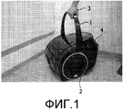
фиг.1 изображает пылесос в положении при переноске;figure 1 depicts a vacuum cleaner in a carrying position;
фиг.2 представляет собой вид в перспективе пылесоса;figure 2 is a perspective view of a vacuum cleaner;
фиг.3 изображает другой вид в перспективе пылесоса; иfigure 3 depicts another perspective view of a vacuum cleaner; and
фиг.4 представляет собой схематичный вид в разрезе сенсорного средства.4 is a schematic sectional view of a sensor means.
Подробное описание варианта осуществленияDetailed Description of Embodiment
Фиг.1-3 изображают вариант осуществления робота-пылесоса, содержащего шарнирную ручку 1 для переноски устройства. Пылесос содержит два ведомых колеса 2, расположенных на обеих сторонах устройства (фигуры изображают только одно из этих колес). Кроме того, он содержит ролик, который может вращаться вокруг вертикальной оси так, что пылесос может перемещаться в любом направлении, ролик расположен на нижней стороне пылесоса и не виден на фигурах. Приведением в движение двух колес 2 независимо с заданными скоростями пылесос может перемещаться по полу комнаты в любом необходимом меняющемся направлении во время своей работы.1-3 show an embodiment of a robot cleaner comprising a
Фиг.1 изображает ручку 1 в вертикальном положении, так что пылесос можно переносить рукой 3, как изображено на фигуре. Фиг.2 изображает ручку во втором положении, являющемся положением во время работы робота-пылесоса. Фиг.3 изображает пылесос с другой стороны. Ручка 1 пылесоса функционирует как элемент обнаружения во время работы пылесоса, при этом ручка находится во втором положении, как изображено на фиг.2 и 3. Ручка 1 достигает наружной стороны корпуса 4 пылесоса, так что ручка 1 может устанавливать физический контакт с неподвижными объектами в окружении, когда пылесос перемещается по полу комнаты, которую необходимо почистить.Figure 1 depicts the
Стрелки 5, 6, 7, 8 на фиг.3 указывают направление, в котором неподвижные объекты могут ударяться о ручку 1, когда пылесос перемещается по полу во время работы. Когда пылесос перемещается под очень низким столом, ручка 1 будет продвигаться вниз, как указано стрелкой 5. Перемещение вниз ручки 1 будет обнаруживаться микровыключателем, как будет объяснено ниже, в результате чего генерируется сигнал управления для изменения направления перемещения устройства, например, на противоположное направление. Когда пылесос перемещается влево (на фиг.3), столкновение с неподвижным объектом будет продвигать ручку 1 в направлении, указанном стрелкой 6. Перемещение ручки 1 будет обнаружено одним или более микровыключателями для генерирования соответствующего сигнала управления для изменения направления перемещения пылесоса, так что можно уклониться от неподвижного объекта.
В частности, когда пылесос следует по криволинейной траектории, ручка 1 может продвигаться в сторону неподвижным объектом, как указано стрелками 7 и 8. Такое столкновение пылесоса с неподвижным объектом также обнаруживается микровыключателями, измеряющими перемещение ручки 1, так что соответствующий сигнал управления генерируется для изменения направления перемещения устройства.In particular, when the vacuum cleaner follows a curved path,
Фиг.4 изображает схематичный вид в разрезе сенсорного средства для обнаружения перемещения ручки 1. Ручка 1 установлена на валу 10 и может поворачиваться вокруг вала 10. Вал 10 продолжается через корпус 4 пылесоса, при этом два конца вала 10 достигают с наружной стороны корпуса 4 пылесоса. Каждый конец ручки 1 соединен с концом вала 10, так что между ручкой 1 и остальной частью пылесоса достигается прочное соединение. Вал 10 соединен с корпусом 4 пылесоса через элемент 11, являющийся частью корпуса 4. Вал 10 может перемещаться влево (на фиг.4) в отношении элемента 11, но продвигается вправо посредством цилиндрической пружины 12.Figure 4 depicts a schematic sectional view of a sensor means for detecting the movement of the
Когда ручка 1 находится во втором положении, как изображено на фиг.4, ручка 1 удерживается в этом положении посредством шарика 13, нагруженного пружиной, так что шарик 13 взаимодействует с соответствующим углублением в валу 10. В указанном втором положении цилиндрическая пружина 14 продвигает шарик 13 в это углубление, и когда ручка 1 перемещается немного из второго указанного положения, цилиндрическая пружина 14 обеспечивает усилие для перемещения ручки 1 обратно во второе положение. Когда ручка 1 находится в вертикальном положении, как изображено на фиг.1, шарик 13 опирается на цилиндрическую поверхность на верхней стороне вала 10.When the
Когда робот-пылесос работает, ручка 1 функционирует как датчик для обнаружения физического контакта, т.е. столкновения, с неподвижными объектами в окружении перемещающегося пылесоса. Когда к ручке не прилагается усилие, ручка удерживается во втором положении цилиндрическими пружинами 12 и 14, эти пружины 12 и 14 находятся около обоих концов вала 10 и ручки 1. В момент, когда к ручке 1 прилагается направленное вниз усилие, как указано стрелкой 15 (на фиг.3 стрелкой 5), ручка 1 будет поворачиваться немного вокруг вала 10 в направлении по часовой стрелке, против толкающего усилия цилиндрической пружины 14. Такое перемещение ручки 1 обнаруживается микровыключателем 16, который прикрепляется к кожуху 17 корпуса 4 пылесоса. Когда микровыключатель 16 приводится в действие, генерируется сигнал управления для изменения направления перемещения пылесоса.When the robot cleaner is operating, the
Чтобы обнаружить перемещения ручки 1 в, по существу, горизонтальной плоскости, как указано стрелкой 19 (на фиг.3 стрелками 6, 7, 8), микровыключатель 18 находится на каждом конце ручки 1. Микровыключатель 18 также прикреплен к кожуху 17 корпуса 4 пылесоса и приводится в действие, когда ручка 1 находится во втором положении. Перемещение ручки 1, как указано стрелкой 19, делает неактивным микровыключатель 18, в результате чего генерируется сигнал управления для изменения направления перемещения робота-пылесоса. В случае если только один из двух микровыключателей 18 на каждом конце ручки 1 обнаруживает перемещение ручки 1, происходит перемещение в сторону ручки 1, при этом может генерироваться соответствующий сигнал управления.In order to detect the movements of the
Несмотря на то, что изобретение пояснено на чертеже и в вышеизложенном описании, такое изображение и описание являются иллюстративными или примерными и не ограничительными; изобретение не ограничивается раскрытым вариантом осуществления. Любые ссылочные обозначения в формуле изобретения не следует истолковывать как ограничение объема изобретения.Although the invention is illustrated in the drawing and in the foregoing description, such an image and description are illustrative or exemplary and not restrictive; the invention is not limited to the disclosed embodiment. Any reference signs in the claims should not be construed as limiting the scope of the invention.
Claims (7)
Applications Claiming Priority (3)
| Application Number | Priority Date | Filing Date | Title |
|---|---|---|---|
| EP08168199A EP2189094A1 (en) | 2008-11-03 | 2008-11-03 | A robotic vacuum cleaner comprising a sensing handle |
| EP08168199.1 | 2008-11-03 | ||
| PCT/IB2009/054728 WO2010061299A1 (en) | 2008-11-03 | 2009-10-26 | A robotic vacuum cleaner comprising a sensing handle |
Publications (2)
| Publication Number | Publication Date |
|---|---|
| RU2011122468A RU2011122468A (en) | 2012-12-10 |
| RU2509520C2 true RU2509520C2 (en) | 2014-03-20 |
Family
ID=40547757
Family Applications (1)
| Application Number | Title | Priority Date | Filing Date |
|---|---|---|---|
| RU2011122468/12A RU2509520C2 (en) | 2008-11-03 | 2009-10-26 | Vacuum cleaner robot containing sensory handle |
Country Status (12)
| Country | Link |
|---|---|
| US (1) | US8296899B2 (en) |
| EP (2) | EP2189094A1 (en) |
| JP (1) | JP5411940B2 (en) |
| KR (1) | KR101562381B1 (en) |
| CN (2) | CN102202550B (en) |
| AT (1) | ATE547974T1 (en) |
| BR (1) | BRPI0914397A2 (en) |
| DE (1) | DE202009014405U1 (en) |
| MX (1) | MX2011004566A (en) |
| PL (1) | PL2352408T3 (en) |
| RU (1) | RU2509520C2 (en) |
| WO (1) | WO2010061299A1 (en) |
Families Citing this family (11)
| Publication number | Priority date | Publication date | Assignee | Title |
|---|---|---|---|---|
| EP2189094A1 (en) * | 2008-11-03 | 2010-05-26 | Koninklijke Philips Electronics N.V. | A robotic vacuum cleaner comprising a sensing handle |
| US8532860B2 (en) * | 2011-02-25 | 2013-09-10 | Intellibot Robotics Llc | Methods and systems for automatically yielding to high-priority traffic |
| DE102011083515B4 (en) * | 2011-09-27 | 2014-09-04 | BSH Bosch und Siemens Hausgeräte GmbH | vacuum cleaner housing |
| KR101853977B1 (en) * | 2012-05-10 | 2018-06-14 | 엘지전자 주식회사 | Cleaning apparatus for window and method of controlling the same |
| US9757004B2 (en) | 2015-02-12 | 2017-09-12 | Irobot Corporation | Liquid management for floor-traversing robots |
| US11039722B2 (en) | 2018-04-23 | 2021-06-22 | Sharkninja Operating Llc | Assisted drive for surface cleaning devices |
| CN108903772B (en) * | 2018-08-02 | 2024-03-08 | 天佑电器(苏州)有限公司 | Cover body assembly and dust collector with same |
| EP3616588B1 (en) | 2018-08-28 | 2021-03-17 | BSH Hausgeräte GmbH | Vacuum cleaner with a handle for carrying the vacuum cleaner |
| CN111374614A (en) * | 2020-03-19 | 2020-07-07 | 北京小米移动软件有限公司 | Control method and device of cleaning equipment and storage medium |
| DE102020113525A1 (en) | 2020-05-19 | 2021-11-25 | Alfred Kärcher SE & Co. KG | Suction device |
| DE102020113521A1 (en) | 2020-05-19 | 2021-11-25 | Alfred Kärcher SE & Co. KG | Suction device |
Citations (4)
| Publication number | Priority date | Publication date | Assignee | Title |
|---|---|---|---|---|
| US5341540A (en) * | 1989-06-07 | 1994-08-30 | Onet, S.A. | Process and autonomous apparatus for the automatic cleaning of ground areas through the performance of programmed tasks |
| WO2000036970A1 (en) * | 1998-12-18 | 2000-06-29 | Dyson Limited | Portable appliance |
| US20040049877A1 (en) * | 2002-01-03 | 2004-03-18 | Jones Joseph L. | Autonomous floor-cleaning robot |
| WO2004058032A1 (en) * | 2002-12-23 | 2004-07-15 | BSH Bosch und Siemens Hausgeräte GmbH | Vacuum cleaner provided with an auxiliary pull-out device for an electrical cable |
Family Cites Families (10)
| Publication number | Priority date | Publication date | Assignee | Title |
|---|---|---|---|---|
| GB2344777A (en) * | 1998-12-18 | 2000-06-21 | Notetry Ltd | Horizontal cyclonic separator with single fin or baffle |
| US7571511B2 (en) * | 2002-01-03 | 2009-08-11 | Irobot Corporation | Autonomous floor-cleaning robot |
| US6766556B2 (en) * | 2001-03-13 | 2004-07-27 | Franc Gergek | Apparatus for cleaning surfaces with automatic water supply and drain |
| KR100922506B1 (en) * | 2001-03-16 | 2009-10-20 | 비젼 로보틱스 코포레이션 | Autonomous canister vacuum cleaner, system thereof and method of vacuum cleaning using the same |
| JP2003169769A (en) * | 2001-12-05 | 2003-06-17 | Amenity Technos:Kk | Self-propelled cleaner |
| JP2003280740A (en) * | 2002-03-25 | 2003-10-02 | Matsushita Electric Ind Co Ltd | Movable device |
| US7712182B2 (en) * | 2003-07-25 | 2010-05-11 | Milwaukee Electric Tool Corporation | Air flow-producing device, such as a vacuum cleaner or a blower |
| US7725223B2 (en) * | 2003-09-30 | 2010-05-25 | Techtronic Floor Care Technology Limited | Control arrangement for a propulsion unit for a self-propelled floor care appliance |
| CN2843326Y (en) * | 2005-06-22 | 2006-12-06 | 王冬雷 | Robot dust collector |
| EP2189094A1 (en) * | 2008-11-03 | 2010-05-26 | Koninklijke Philips Electronics N.V. | A robotic vacuum cleaner comprising a sensing handle |
-
2008
- 2008-11-03 EP EP08168199A patent/EP2189094A1/en not_active Ceased
-
2009
- 2009-10-26 US US13/126,059 patent/US8296899B2/en active Active
- 2009-10-26 WO PCT/IB2009/054728 patent/WO2010061299A1/en active Application Filing
- 2009-10-26 JP JP2011533871A patent/JP5411940B2/en not_active Expired - Fee Related
- 2009-10-26 RU RU2011122468/12A patent/RU2509520C2/en not_active IP Right Cessation
- 2009-10-26 KR KR1020117012549A patent/KR101562381B1/en active IP Right Grant
- 2009-10-26 CN CN200980143480.4A patent/CN102202550B/en active Active
- 2009-10-26 EP EP09745126A patent/EP2352408B1/en active Active
- 2009-10-26 MX MX2011004566A patent/MX2011004566A/en active IP Right Grant
- 2009-10-26 BR BRPI0914397A patent/BRPI0914397A2/en not_active IP Right Cessation
- 2009-10-26 AT AT09745126T patent/ATE547974T1/en active
- 2009-10-26 PL PL09745126T patent/PL2352408T3/en unknown
- 2009-10-27 DE DE202009014405U patent/DE202009014405U1/en not_active Expired - Lifetime
- 2009-11-02 CN CN2009202695921U patent/CN201847612U/en not_active Expired - Fee Related
Patent Citations (4)
| Publication number | Priority date | Publication date | Assignee | Title |
|---|---|---|---|---|
| US5341540A (en) * | 1989-06-07 | 1994-08-30 | Onet, S.A. | Process and autonomous apparatus for the automatic cleaning of ground areas through the performance of programmed tasks |
| WO2000036970A1 (en) * | 1998-12-18 | 2000-06-29 | Dyson Limited | Portable appliance |
| US20040049877A1 (en) * | 2002-01-03 | 2004-03-18 | Jones Joseph L. | Autonomous floor-cleaning robot |
| WO2004058032A1 (en) * | 2002-12-23 | 2004-07-15 | BSH Bosch und Siemens Hausgeräte GmbH | Vacuum cleaner provided with an auxiliary pull-out device for an electrical cable |
Also Published As
| Publication number | Publication date |
|---|---|
| EP2352408B1 (en) | 2012-03-07 |
| US8296899B2 (en) | 2012-10-30 |
| PL2352408T3 (en) | 2012-08-31 |
| CN102202550B (en) | 2014-01-29 |
| CN201847612U (en) | 2011-06-01 |
| CN102202550A (en) | 2011-09-28 |
| RU2011122468A (en) | 2012-12-10 |
| KR101562381B1 (en) | 2015-10-22 |
| US20110203072A1 (en) | 2011-08-25 |
| KR20110091734A (en) | 2011-08-12 |
| MX2011004566A (en) | 2011-06-01 |
| ATE547974T1 (en) | 2012-03-15 |
| BRPI0914397A2 (en) | 2015-10-20 |
| WO2010061299A1 (en) | 2010-06-03 |
| EP2189094A1 (en) | 2010-05-26 |
| EP2352408A1 (en) | 2011-08-10 |
| DE202009014405U1 (en) | 2010-01-14 |
| JP2012507328A (en) | 2012-03-29 |
| JP5411940B2 (en) | 2014-02-12 |
Similar Documents
| Publication | Publication Date | Title |
|---|---|---|
| RU2509520C2 (en) | Vacuum cleaner robot containing sensory handle | |
| JP5628171B2 (en) | Mobile robot device with collision sensor | |
| KR101322970B1 (en) | Robotic cleaning device | |
| AU2013203861B2 (en) | Method of controlling automatic cleaner | |
| EP2433541A1 (en) | Robot cleaner | |
| US20150027493A1 (en) | Window cleaning apparatus capable of manipulation via magnetic attraction and control method thereof | |
| KR100711972B1 (en) | Robot for Cleaner and Cleaning Method | |
| KR20080105542A (en) | Cleanning robot | |
| US20160051104A1 (en) | Cleaning robot having expanded cleaning territory | |
| JP2006155274A (en) | Self-travelling cleaner | |
| CN101926631A (en) | The method that moves of robot cleaner and this robot cleaner of control | |
| WO2022127443A1 (en) | Autonomous mobile device | |
| KR101292125B1 (en) | a robot cleaner | |
| KR20060095657A (en) | Robot cleaner | |
| US20240000279A1 (en) | Robot with obstacle-detecting deformation sensors | |
| KR20110048375A (en) | Robot cleaner | |
| KR101052108B1 (en) | Vacuum cleaner | |
| KR20150139732A (en) | Robot cleaner | |
| CN220512799U (en) | Mobile cleaning robot | |
| CN219289325U (en) | Translational self-propelled surface cleaning machine | |
| EP4321077A1 (en) | Self-propelled cleaning machine | |
| KR20020045630A (en) | Electric vacuum cleaner based on remote control | |
| KR100816901B1 (en) | Recognition system of Robot cleaner | |
| JP2022041833A (en) | Autonomous travel type cleaner |
Legal Events
| Date | Code | Title | Description |
|---|---|---|---|
| MM4A | The patent is invalid due to non-payment of fees |
Effective date: 20191027 |