RU2507504C2 - Modular device and method to rotate glass vessels and similar items - Google Patents
Modular device and method to rotate glass vessels and similar items Download PDFInfo
- Publication number
- RU2507504C2 RU2507504C2 RU2009138355/03A RU2009138355A RU2507504C2 RU 2507504 C2 RU2507504 C2 RU 2507504C2 RU 2009138355/03 A RU2009138355/03 A RU 2009138355/03A RU 2009138355 A RU2009138355 A RU 2009138355A RU 2507504 C2 RU2507504 C2 RU 2507504C2
- Authority
- RU
- Russia
- Prior art keywords
- belt
- rotation
- glass vessel
- glass
- test station
- Prior art date
Links
Images
Classifications
-
- B—PERFORMING OPERATIONS; TRANSPORTING
- B07—SEPARATING SOLIDS FROM SOLIDS; SORTING
- B07C—POSTAL SORTING; SORTING INDIVIDUAL ARTICLES, OR BULK MATERIAL FIT TO BE SORTED PIECE-MEAL, e.g. BY PICKING
- B07C5/00—Sorting according to a characteristic or feature of the articles or material being sorted, e.g. by control effected by devices which detect or measure such characteristic or feature; Sorting by manually actuated devices, e.g. switches
- B07C5/04—Sorting according to size
- B07C5/12—Sorting according to size characterised by the application to particular articles, not otherwise provided for
- B07C5/122—Sorting according to size characterised by the application to particular articles, not otherwise provided for for bottles, ampoules, jars and other glassware
- B07C5/126—Sorting according to size characterised by the application to particular articles, not otherwise provided for for bottles, ampoules, jars and other glassware by means of photo-electric sensors, e.g. according to colour
-
- B—PERFORMING OPERATIONS; TRANSPORTING
- B07—SEPARATING SOLIDS FROM SOLIDS; SORTING
- B07C—POSTAL SORTING; SORTING INDIVIDUAL ARTICLES, OR BULK MATERIAL FIT TO BE SORTED PIECE-MEAL, e.g. BY PICKING
- B07C5/00—Sorting according to a characteristic or feature of the articles or material being sorted, e.g. by control effected by devices which detect or measure such characteristic or feature; Sorting by manually actuated devices, e.g. switches
- B07C5/34—Sorting according to other particular properties
- B07C5/3404—Sorting according to other particular properties according to properties of containers or receptacles, e.g. rigidity, leaks, fill-level
- B07C5/3408—Sorting according to other particular properties according to properties of containers or receptacles, e.g. rigidity, leaks, fill-level for bottles, jars or other glassware
-
- G—PHYSICS
- G01—MEASURING; TESTING
- G01N—INVESTIGATING OR ANALYSING MATERIALS BY DETERMINING THEIR CHEMICAL OR PHYSICAL PROPERTIES
- G01N21/00—Investigating or analysing materials by the use of optical means, i.e. using sub-millimetre waves, infrared, visible or ultraviolet light
- G01N21/84—Systems specially adapted for particular applications
- G01N21/88—Investigating the presence of flaws or contamination
- G01N21/90—Investigating the presence of flaws or contamination in a container or its contents
- G01N21/9009—Non-optical constructional details affecting optical inspection, e.g. cleaning mechanisms for optical parts, vibration reduction
Landscapes
- General Health & Medical Sciences (AREA)
- Physics & Mathematics (AREA)
- Life Sciences & Earth Sciences (AREA)
- Chemical & Material Sciences (AREA)
- Analytical Chemistry (AREA)
- Biochemistry (AREA)
- Health & Medical Sciences (AREA)
- General Physics & Mathematics (AREA)
- Immunology (AREA)
- Pathology (AREA)
- Investigating Materials By The Use Of Optical Means Adapted For Particular Applications (AREA)
- Investigating Strength Of Materials By Application Of Mechanical Stress (AREA)
- Specific Conveyance Elements (AREA)
- Re-Forming, After-Treatment, Cutting And Transporting Of Glass Products (AREA)
Abstract
Description
УРОВЕНЬ ТЕХНИКИBACKGROUND
Область техники, к которой относится изобретениеFIELD OF THE INVENTION
Настоящее изобретение в общем относится к устройствам и способам вращения стеклянных сосудов и подобных изделий с целью их проверки, и более конкретно: к усовершенствованному компактному модульному устройству и способу вращения таких изделий, в котором посредством новой системы привода, которая автоматически прилагает к этим изделиям только контактное усилие, необходимое для их вращения, производится их более быстрое ускорение до полной скорости вращения.The present invention generally relates to devices and methods for rotating glass vessels and similar products for the purpose of checking them, and more specifically: to an improved compact modular device and method for rotating such products, in which, by means of a new drive system, which automatically applies only contact contact to these products the force required for their rotation, their faster acceleration to a full speed of rotation.
Стеклянные сосуды изготавливаются в ходе производственного процесса, который имеет три части, а именно: смесительное помещение, горячая часть и холодная часть. Смесительное помещение - это где подготавливаются и смешиваются в замесы исходные материалы для производства стекла (которые, обычно, могут включать песок, кальцинированную соду, известняк, стекольный бой (измельченное переработанное стекло), а также другое сырье). Горячая часть начинается с печи, в которой смешанные материалы плавятся и превращаются в расплавленное стекло и из которой вытекает поток расплавленного стекла.Glass vessels are made during the manufacturing process, which has three parts, namely: a mixing room, a hot part and a cold part. A mixing room is where glass-making raw materials are prepared and blended (which can usually include sand, soda ash, limestone, glass break (ground recycled glass), and other raw materials). The hot portion begins with a furnace in which mixed materials melt and turn into molten glass and from which a stream of molten glass flows.
Литое стекло разрезается на цилиндры стекла, называемые «каплями», которые под действием своего веса падают в пустые литейные формы. В этих пустых литейных формах формируется называемые черновыми заготовки сосудов - либо с использованием металлического пуансона, который заталкивает стекло в пустую форму, либо выдуванием стекла в пустую форму снизу. Черновая заготовка инвертируется и передается в форму, в которой эта черновая заготовка выдувается, приобретая форму сосуда. Горячая часть включает также процесс отжига, который предотвращает ослабление стекла сосудов, вызванное внутренними напряжениями из-за неравномерного охлаждения. Процесс отжига используется для достижения равномерного охлаждения, он выполняется в отжиговой печи или в лере, в которой сосуды нагревают, а затем в течение от двадцати до шестидесяти минут медленно охлаждают.Cast glass is cut into glass cylinders, called “drops,” which, under the influence of their weight, fall into empty molds. In these empty casting molds, vessel blanks called draft are formed — either using a metal punch that pushes the glass into the empty mold, or by blowing the glass into the empty mold from below. The draft blank is inverted and transferred to the form in which this draft blank is blown, acquiring the shape of a vessel. The hot part also includes an annealing process, which prevents the weakening of the glass vessels caused by internal stresses due to uneven cooling. The annealing process is used to achieve uniform cooling; it is carried out in an annealing furnace or in a lehr, in which the vessels are heated, and then slowly cooled for twenty to sixty minutes.
Роль холодной части процесса производства стеклянного сосуда состоит в проверке сосудов, чтобы убедиться в том, что они имеют приемлемое качество. Все стеклянные сосуды после их производства проверяются автоматическими станками на отсутствие множества дефектов, обычно включающих небольшие трещины в толще стекла, называемые микротрещинами, посторонние включения, называемые камнями, пузырьки в стекле, называемые блистерами, а также слишком тонкие стенки. Многие из этих проверок выполняются при вращении стеклянных сосудов, чтобы проверить эти стеклянные сосуды со всех их сторон, или по меньшей мере с нескольких мест, расположенных под различными углами относительно этих стеклянных сосудов. Кроме того, многие из стеклянных сосудов включают «пяточный код», который представляет собой код формы, нанесенный на «пяту» каждого стеклянного сосуда (скругленная часть, где горизонтальная плоскость основания переходит в вертикальный цилиндр, называемая также «insweep»), который идентифицирует конкретную форму, в которую был выдут данный стеклянный сосуд. См., например, патент US 5028769, Claypool et al., который переуступлен правопреемнику настоящего изобретения и который включен в данное описание путем ссылки.The role of the cold part of the glass vessel manufacturing process is to inspect the vessels to ensure that they are of acceptable quality. All glass vessels after their production are checked by automatic machines for the absence of many defects, usually including small cracks in the thickness of the glass, called microcracks, foreign inclusions, called stones, bubbles in the glass, called blisters, and also too thin walls. Many of these checks are performed by rotating the glass vessels in order to check these glass vessels from all sides, or from at least several places located at different angles relative to these glass vessels. In addition, many of the glass vessels include a “heel code”, which is a shape code printed on the “heel” of each glass vessel (the rounded part where the horizontal plane of the base goes into the vertical cylinder, also called the “insweep”), which identifies a particular the form into which this glass vessel was blown. See, for example, patent US 5028769, Claypool et al., Which is assigned to the assignee of the present invention and which is incorporated into this description by reference.
Поскольку эти проверки выполняются как часть крупномасштабного производственного процесса, то специалистам в данной области техники будет ясно, что проверки должны выполняться с большой скоростью, например со скоростью проверок примерно в 400 стеклянных сосудов в минуту. То есть за время приблизительно в 150 миллисекунд стеклянный сосуд должен быть установлен на проверочную станцию, провернут примерно на полтора оборота и удален из этой проверочной станции, в то время как на нее устанавливается другой стеклянный сосуд.Since these checks are performed as part of a large-scale production process, it will be apparent to those skilled in the art that the checks must be performed at high speed, for example at a speed of checks of about 400 glass vessels per minute. That is, in a time of approximately 150 milliseconds, the glass vessel must be installed on the test station, turned about one and a half turns and removed from this test station, while another glass vessel is installed on it.
Обычно проверочная станция расположена либо на шаговом конвейере со звездочкой, имеющем верхнюю и нижнюю карусель с вырезами для приема стеклянных сосудов (как показано, например, в патенте US 3957154, Shiba), или на прямолинейной проверочной части конвейера, имеющей устройство для вращения стеклянных сосудов, расположенное в одном или в нескольких требуемых положениях на прямолинейном конвейере, определяющем путь или направление конвейера (как показано, например, в патенте US 5608516, Emery). В любом случае проверочная станция будет иметь пару роликов, которые удерживают стеклянный сосуд около его верхней части с одной стороны стеклянного сосуда и вторую пару роликов, которые удерживают стеклянный сосуд ближе к его дну с той же стороны стеклянного сосуда. Приводной ролик касается стеклянного сосуда со стороны, противоположной той стороне, где он удерживается двумя парами роликов, приводится во вращение приводным механизмом и вызывает вращение стеклянного сосуда между приводным роликом и двумя парами роликов, удерживающих соответственно верхнюю часть и дно стеклянного сосуда.Typically, the test station is located either on a step conveyor with an asterisk having an upper and lower carousel with cutouts for receiving glass vessels (as shown, for example, in US Pat. No. 3,957,154, Shiba), or on a straight-line test part of a conveyor having a device for rotating glass vessels, located in one or more of the required positions on a straight conveyor defining the path or direction of the conveyor (as shown, for example, in patent US 5608516, Emery). In any case, the test station will have a pair of rollers that hold the glass vessel near its upper part on one side of the glass vessel and a second pair of rollers that hold the glass vessel closer to its bottom on the same side of the glass vessel. The drive roller touches the glass vessel from the side opposite to the side where it is held by two pairs of rollers, is driven by the drive mechanism and causes the glass vessel to rotate between the drive roller and two pairs of rollers holding the upper part and the bottom of the glass vessel, respectively.
Приводной ролик вызывает вращение стеклянного сосуда между приводным роликом и двумя парами роликов, и во время вращения стеклянного сосуда могут проводиться различные проверки. Такие проверки могут быть по своей природе оптическими или механическими, и обычно они выполняются по мере поворота стеклянного сосуда под множеством нарастающих углов. Приводной ролик обычно работает непрерывно (независимо от того, находится ли он в контакте со стеклянными сосудами или нет) и расположен около линии, пересекаемой стеклянными сосудами, на месте против двух пар роликов.The drive roller causes the glass vessel to rotate between the drive roller and two pairs of rollers, and various checks can be made during rotation of the glass vessel. Such checks may be optical or mechanical in nature, and they are usually performed as the glass vessel rotates under a multitude of increasing angles. The drive roller usually operates continuously (regardless of whether it is in contact with the glass vessels or not) and is located near the line crossed by the glass vessels, in place against two pairs of rollers.
Для управления приводным роликом, используемым для вращения стеклянных сосудов, и его позиционирования на проверочных станциях в промышленности используются два различных типа приводных механизмов. Первый такой приводной механизм представляет собой устройство, которое целиком установлено с возможностью поворота относительно горизонтальной оси, таким образом, что поворачивается весь механизм, причем приводной ролик поворачивается в вертикальной плоскости в направлении к приводимому во вращение стеклянному сосуду и от него, и при этом приводной ролик имеет пружинное смещение в направлении стеклянного сосуда (как показано, например, в патенте US 3957154). Это приводное устройство, будучи установлено в линии высокоскоростных проверок (400 сосудов в минуту), является очень «жестким» по отношению к стеклянным сосудам, поскольку вследствие большой массы приводного узла оно ударяет по сосудам наподобие молотка, повреждая их, и, кроме того, оно имеет серьезные вопросы, связанные с надежностью.Two different types of drive mechanisms are used to control the drive roller used to rotate the glass vessels and position it at test stations in industry. The first such drive mechanism is a device that is wholly mounted to rotate about a horizontal axis so that the entire mechanism rotates, and the drive roller is rotated in a vertical plane in the direction of the glass vessel driven and rotated, and the drive roller has a spring displacement in the direction of the glass vessel (as shown, for example, in patent US 3957154). This drive device, being installed in the line of high-speed inspections (400 vessels per minute), is very “rigid” with respect to glass vessels, because due to the large mass of the drive unit it hits the vessels like a hammer, damaging them, and, moreover, it has serious reliability issues.
Второй такой приводной механизм представляет собой устройство, которое установлено с возможностью смещения, в котором часть устройства, включающая приводной ролик, установлена с осевым вращением относительно вертикальной оси таким образом, что приводной ролик поворачивается в горизонтальной плоскости в направлении к приводимому во вращение стеклянному сосуду и от него, и при этом приводной ролик имеет пружинное смещение в направлении стеклянного сосуда (как показано, например, в патенте US 5608516). Это приводное устройство имеет меньшую подвижную массу и, таким образом, не является столь «жестким» по отношению к стеклянным сосудам, но оно более дорогое в изготовлении, требует больше пространства рядом с траекторией движения стеклянных сосудов и также имеет серьезные вопросы по надежности.A second such drive mechanism is a device which is biasably mounted in which a part of the device including the drive roller is axially rotated about a vertical axis such that the drive roller rotates in a horizontal plane towards and away from the rotatable glass vessel him, and while the drive roller has a spring bias in the direction of the glass vessel (as shown, for example, in patent US 5608516). This drive device has a smaller moving mass and, therefore, is not so "rigid" in relation to glass vessels, but it is more expensive to manufacture, requires more space near the trajectory of the glass vessels and also has serious questions about reliability.
Соответственно, главной целью настоящего изобретения является то, чтобы оно представляло улучшенное устройство для вращения стеклянных сосудов, которое в высшей степени компактно, что позволяет ему занимать минимальный объем в зоне около вращаемого стеклянного сосуда, оставляя тем самым максимально возможное пространство для проверочной аппаратуры. Другой главной целью настоящего изобретения является то, чтобы, несмотря на свои компактные размеры, оно было способно сообщать стеклянному сосуду достаточный вращающий момент для его быстрого ускорения, чтобы минимизировать время, необходимое для проверки каждого стеклянного сосуда. Связанной целью настоящего изобретения является то, чтобы оно представляло в высокой степени податливую поверхность привода и, кроме того, демонстрировало повышенную способность быстрого «схватывания» внешней стенки стеклянного сосуда, что позволяло бы быстро преодолеть его инерционность и раскрутить его до нужной скорости.Accordingly, the main objective of the present invention is that it provides an improved device for rotating glass vessels, which is extremely compact, which allows it to occupy a minimum volume in the area near the rotating glass vessel, thereby leaving the maximum possible space for testing equipment. Another main objective of the present invention is that, in spite of its compact dimensions, it is capable of imparting sufficient momentum to the glass vessel for its rapid acceleration in order to minimize the time required to inspect each glass vessel. A related objective of the present invention is that it represents a highly pliable drive surface and, in addition, exhibits an increased ability to quickly “set” the outer wall of the glass vessel, which would quickly overcome its inertia and spin it to the desired speed.
Еще одной главной целью настоящего изобретения является то, чтобы оно характеризовалось низкой степенью ударного воздействия на стеклянные сосуды и обладало уникальной способностью быстрого перемещения для контакта со стеклянным сосудом без его повреждения и без повреждения им. Следующей целью настоящего изобретения является то, чтобы оно было способно создавать приложенную к стеклянному сосуду силу, действующую в направлении вниз, иначе бы он при своем вращении с быстрой скоростью ничем не сдерживался в вертикальном направлении. И еще одной целью настоящего изобретения является то, чтобы оно представляло жесткую механическую конструкцию, обладающую высокой надежностью, исключающую какие-либо производственные потери, обусловленные выходом устройства из строя.Another main objective of the present invention is that it has a low degree of impact on glass vessels and has the unique ability to quickly move to contact the glass vessel without damaging it and without damaging it. The next objective of the present invention is that it is able to create a force applied to the glass vessel, acting in the downward direction, otherwise it would not be restrained in the vertical direction during its rotation with fast speed. And another objective of the present invention is that it represents a rigid mechanical structure with high reliability, eliminating any production losses caused by the failure of the device.
Устройство для вращения стеклянных сосудов по настоящему изобретению неизбежно должно иметь конструкцию, которая, кроме того, является прочной, имеет длительный срок службы и такие конструктивные характеристики, которые позволяют производить ее быстрое техническое обслуживание, хотя в течение всего срока службы оно потребует лишь относительно нечастого технического обслуживания со стороны пользователя.The device for rotating glass vessels of the present invention inevitably must have a structure that, in addition, is durable, has a long service life and design features that allow for its quick maintenance, although it will only require relatively relatively little technical maintenance over the entire service life. service by the user.
Для увеличения коммерческой привлекательности устройства для вращения стеклянных сосудов по настоящему изобретению его конструкция также должна быть недорогой, что тем самым обеспечит ему максимально возможный рынок. Наконец, целью настоящего изобретения является достижение всех вышеупомянутых преимуществ и целей устройства для вращения стеклянных сосудов и способа по настоящему изобретению без внесения в него каких-либо относительно существенных недостатков.To increase the commercial attractiveness of the device for rotating glass vessels of the present invention, its design should also be inexpensive, thereby providing it with the maximum possible market. Finally, the aim of the present invention is to achieve all of the above advantages and goals of the apparatus for rotating glass vessels and the method of the present invention without introducing any relatively significant disadvantages.
СУЩНОСТЬ ИЗОБРЕТЕНИЯSUMMARY OF THE INVENTION
Настоящим изобретением устранены недостатки и ограничения вышеописанных устройств предшествующего уровня техники. Данным изобретением предложено в высокой степени компактное устройство для вращения стеклянных сосудов, которое имеет два основных компонента, а именно: узел основания, который включает в себя электродвигатель, и узел каретки, который установлен на узле основания и который вращает стеклянный сосуд. Устройство для вращения стеклянных сосудов по настоящему изобретению для вращения стеклянного сосуда использует ремень вращения изделий, вращающийся вокруг эластичного колеса вращения изделий. Конструкция «ремень вокруг колеса» позволяет построить очень тонкое и узкое устройство, размеры которого в районе стеклянного сосуда всего лишь немного больше, чем размер самого колеса вращения изделий.The present invention eliminated the disadvantages and limitations of the above devices of the prior art. This invention provides a highly compact device for rotating glass vessels, which has two main components, namely: the base assembly, which includes an electric motor, and the carriage assembly, which is mounted on the base assembly and which rotates the glass vessel. The apparatus for rotating glass vessels of the present invention uses a product rotation belt rotating around an elastic article rotation wheel to rotate a glass vessel. The “belt around the wheel” design allows you to build a very thin and narrow device, the dimensions of which in the region of the glass vessel are only slightly larger than the size of the wheel itself.
Узел основания имеет электродвигатель, который приводит в действие шкив привода ремня, а также включает в себя один холостой шкив. Кроме того, узел основания включает устройство для установки в нем узла каретки таким образом, который позволяет ей совершать скольжение в прямолинейном направлении к стеклянному сосуду (в направлении удаления) или от него (в направлении приближения). В направлении удаления узел каретки подпирается пружинами, расположенными между узлом каретки и узлом основания. Усилие подпора пружин является регулируемым для изменения силы, которая будет приложена к стеклянному сосуду, вошедшему в контакт с устройством для вращения стеклянных сосудов.The base unit has an electric motor that drives the belt drive pulley, and also includes one idle pulley. In addition, the base assembly includes a device for mounting the carriage assembly therein in such a manner that allows it to slide in a straight direction to the glass vessel (in the direction of removal) or away from it (in the direction of approximation). In the direction of removal, the carriage assembly is supported by springs located between the carriage assembly and the base assembly. The spring support is adjustable to change the force that will be applied to the glass vessel that comes into contact with the device for rotating the glass vessels.
Узел каретки включает установленные в нем холостые шкивы, а также узел натяжения ремня, несущий холостой шкив, положение которого может быть регулируемым с целью регулировки натяжения ремня вращения изделий. Ремень вращения изделий является зубчатым ремнем, имеющим идущий в продольном направлении паз, прорезанный в зубьях зубчатого ремня по его центральной линии. Шкив привода ремня в узле основания и колесо вращения изделий, а также два холостых шкива в узле каретки имеют расположенный по центральной линии кольцевой буртик, выступающий наружу относительно зубьев. В упомянутый паз в ремне вращения изделий заходят буртики шкива привода ремня, колеса вращения изделий, а также двух холостых шкивов, что увеличивает способность ремня вращения изделий выдерживать нагрузку, приложенную к его оси вращения (а также позволяет уменьшить высоту устройства для вращения стеклянных сосудов в том месте, где оно подходит к ним).The carriage assembly includes idle pulleys installed therein, as well as a belt tension assembly that carries an idle pulley, the position of which can be adjustable to adjust the tension of the belt of rotation of the products. The product rotation belt is a toothed belt having a longitudinally extending groove cut in the teeth of the toothed belt along its center line. The belt drive pulley in the base assembly and the product rotation wheel, as well as two idle pulleys in the carriage assembly, have an annular bead located in the center line and protruding outward relative to the teeth. The grooves of the belt drive pulley, the wheel of rotation of the products, as well as two idle pulleys, which increases the ability of the belt of rotation of the products to withstand the load applied to its axis of rotation (and also reduces the height of the device for rotating glass vessels in that the place where it comes to them).
Данный подход позволяет всем элементам - ремню вращения изделий, колесу вращения изделий, а также подшипникам колеса вращения изделий иметь общую центральную линию. Такая плоскостная конструкция обеспечивает и более высокий уровень надежности, и значительное сокращение размеров, особенно в зоне, расположенной вблизи проверяемого стеклянного сосуда. Пространство вблизи проверяемого стеклянного сосуда является наиболее ценным пространством для размещения датчиков проверки стеклянного сосуда, и конструкция устройства для вращения стеклянных сосудов по настоящему изобретению максимизирует зону вокруг стеклянного сосуда, которая остается для проверочных датчиков.This approach allows all elements - the belt of rotation of the products, the wheel of rotation of the products, as well as the bearings of the wheel of rotation of the products to have a common center line. Such a planar design provides both a higher level of reliability and a significant reduction in size, especially in the area located near the test glass vessel. The space near the glass jar being inspected is the most valuable space for placing glass jar inspection sensors, and the design of the glass vessel rotation apparatus of the present invention maximizes the area around the glass jar that remains for the jar sensors.
Кроме того, конструкция устройства для вращения стеклянных сосудов по настоящему изобретению оказывает значительно меньшее ударное воздействие на вращаемые им стеклянные сосуды. Прежде всего, усилие подпора пружин является единственной силой, которая воздействует на стеклянный сосуд во время его вращения. Когда стеклянный сосуд находится в процессе начала вращения, конфигурация пути привода ремня вращения изделий приведет к увеличению натяжения в части этого ремня вращения изделий, пока этот стеклянный сосуд ускоряется до полной скорости вращения. Это повышенное натяжение способствует перемещению узла каретки в направлении стеклянного сосуда, создавая дополнительное давление на стеклянный сосуд для увеличения «схватывания» ремнем вращения изделий стеклянного сосуда во время его ускорения. Как только стеклянный сосуд начнет вращаться на своей полной скорости вращения, увеличенное натяжение в ремне вращения изделий исчезает, и узел каретки втягивается назад, при этом дополнительное давление, оказываемое на стеклянный сосуд, также исчезает.In addition, the design of the apparatus for rotating glass vessels of the present invention has a significantly lower impact on the glass vessels it rotates. First of all, the spring backing force is the only force that acts on the glass vessel during its rotation. When the glass vessel is in the process of starting rotation, the configuration of the drive path of the product rotation belt will increase the tension in the part of this product rotation belt while this glass vessel is accelerated to full rotation speed. This increased tension facilitates the movement of the carriage assembly in the direction of the glass vessel, creating additional pressure on the glass vessel to increase the “seizure” of the rotation of the glass vessel products by the belt during its acceleration. As soon as the glass vessel begins to rotate at its full speed of rotation, the increased tension in the belt of rotation of the products disappears, and the carriage assembly is pulled back, while the additional pressure exerted on the glass vessel also disappears.
Таким образом, может быть ясно, что настоящее изобретение обеспечивает устройство для вращения стеклянных сосудов, которое в высшей степени компактно, что позволяет ему занимать минимальный объем в зоне около вращаемого стеклянного сосуда, оставляя тем самым максимально возможное пространство, пригодное для проверочной аппаратуры. Не смотря на компактные размеры устройства для вращения стеклянных сосудов по настоящему изобретению, оно способно сообщать стеклянному сосуду достаточный вращающий момент для его быстрого ускорения, чтобы минимизировать время, необходимое для проверки каждого стеклянного сосуда. Устройство для вращения стеклянных сосудов по настоящему изобретению представляет в высокой степени податливую поверхность привода и, кроме того, демонстрирует повышенную способность быстрого «схватывания» внешней стенки стеклянного сосуда, что позволяет быстро преодолеть его инерционность и раскрутить его до нужной скорости.Thus, it can be clear that the present invention provides a device for rotating glass vessels that is extremely compact, which allows it to occupy a minimum volume in the region near the rotating glass vessel, thereby leaving the maximum possible space suitable for testing equipment. Despite the compact dimensions of the device for rotating glass vessels of the present invention, it is able to provide the glass vessel with sufficient torque to accelerate it quickly to minimize the time required to inspect each glass vessel. The device for rotating glass vessels of the present invention represents a highly pliable drive surface and, in addition, exhibits an increased ability to quickly “set” the outer wall of the glass vessel, which allows it to quickly overcome its inertia and untwist it to the desired speed.
Устройство для вращения стеклянных сосудов по настоящему изобретению характеризуется низкой степенью ударного воздействия на стеклянные сосуды и обладает уникальной способностью быстрого перемещения для контакта со стеклянным сосудом без его повреждения и без повреждения им.The device for rotating glass vessels of the present invention is characterized by a low degree of impact on glass vessels and has a unique ability to quickly move to contact the glass vessel without damaging it and without damaging it.
Устройство для вращения стеклянных сосудов по настоящему изобретению способно также создавать действующую на этот стеклянный сосуд направленную вниз силу и тем самым сдерживать его, придавливая вниз во время его вращения с высокой скоростью. Устройство для вращения стеклянных сосудов по настоящему изобретению является устройством с высокой жесткостью механической конструкции и с высокой надежностью, исключающей какие-либо производственные потери, обусловленные его выходом из строя.The device for rotating glass vessels of the present invention is also capable of creating a downward force acting on this glass vessel and thereby restrain it, pressing down during its rotation at high speed. The device for rotating glass vessels of the present invention is a device with high rigidity of the mechanical structure and with high reliability, eliminating any production losses due to its failure.
Устройство для вращения стеклянных сосудов по настоящему изобретению представляет собой такую конструкцию, которая является и прочной, и имеет длительный срок службы, а также такие конструктивные характеристики, которые позволяют производить ее быстрое техническое обслуживание; кроме того, в течение всего срока службы оно потребует лишь относительно нечастого технического обслуживания со стороны пользователя. Устройство для вращения стеклянных сосудов по настоящему изобретению является, кроме того, конструктивно недорогим, что увеличит его коммерческую привлекательность и тем самым обеспечит ему максимально возможный рынок. Наконец, все вышеупомянутые преимущества и цели устройства для вращения стеклянных сосудов и способа по настоящему изобретению достигнуты без наделения его какими-либо относительно существенными недостатками.The device for rotating glass vessels of the present invention is such a structure that is both durable and has a long service life, as well as such structural characteristics that allow its quick maintenance; in addition, during the entire service life, it will require only relatively infrequent maintenance by the user. The device for rotating glass vessels of the present invention is, in addition, structurally inexpensive, which will increase its commercial attractiveness and thereby provide it with the maximum possible market. Finally, all of the above advantages and goals of the apparatus for rotating glass vessels and the method of the present invention are achieved without endowing it with any relatively significant disadvantages.
ОПИСАНИЕ ЧЕРТЕЖЕЙDESCRIPTION OF DRAWINGS
Эти и другие преимущества настоящего изобретения будут более понятны при обращении к чертежам, на которых:These and other advantages of the present invention will be better understood when referring to the drawings, in which:
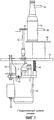
Фиг. 1 представляет собой вид сбоку первого известного в настоящее время устройства для вращения стеклянных сосудов.FIG. 1 is a side view of a first currently known device for rotating glass vessels.
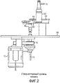
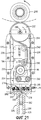
Фиг. 2 представляет собой вид сбоку второго известного в настоящее время устройства для вращения стеклянных сосудов.FIG. 2 is a side view of a second currently known device for rotating glass vessels.
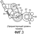
Фиг. 3 представляет собой вид сверху второго известного в настоящее время устройства для вращения стеклянных сосудов, показанного на фиг. 2.FIG. 3 is a top view of the second currently known glass vessel rotation apparatus shown in FIG. 2.
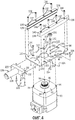
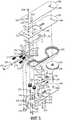
Фиг. 4 представляет собой покомпонентный изометрический вид, показывающий различные компоненты узла корпуса устройства для вращения стеклянных сосудов, выполненного в соответствии с настоящим изобретением.FIG. 4 is an exploded isometric view showing various components of a housing assembly of a glass vessel rotation apparatus in accordance with the present invention.
Фиг. 5 представляет собой покомпонентный изометрический вид, показывающий различные компоненты узла каретки устройства для вращения стеклянных сосудов, выполненного в соответствии с принципами настоящего изобретения и предназначенного для использования с узлом корпуса, показанным на фиг. 4.FIG. 5 is an exploded isometric view showing various components of a carriage assembly of a glass vessel rotation apparatus in accordance with the principles of the present invention and for use with the cabinet assembly shown in FIG. four.
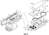
Фиг. 6 представляет собой частично покомпонентный изометрический вид, иллюстрирующий сборку узла каретки, показанного на фиг. 5, на узле корпуса, показанном на фиг. 4, причем узел каретки в узле корпуса еще не установлен.FIG. 6 is a partially exploded isometric view illustrating the assembly of the carriage assembly of FIG. 5, on the housing assembly shown in FIG. 4, wherein the carriage assembly in the housing assembly is not yet installed.
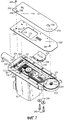
Фиг. 7 представляет собой частично покомпонентный изометрический вид, показывающий проиллюстрированные на фиг. 6 узел каретки и узел корпуса, причем узел каретки частично установлен в узел корпуса.FIG. 7 is a partially exploded isometric view showing those illustrated in FIG. 6, a carriage assembly and a housing assembly, the carriage assembly being partially installed in the housing assembly.
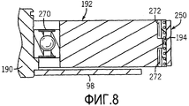
Фиг. 8 представляет собой сечение, на котором показана часть ремня вращения изделий, а также часть колеса вращения изделий.FIG. 8 is a sectional view showing a part of a product rotation belt and a part of a product rotation wheel.
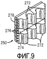
Фиг. 9 представляет собой изометрический вид поперечного сечения ремня вращения изделий.FIG. 9 is an isometric cross-sectional view of an article rotation belt.
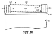
Фиг. 10 представляет собой вид со стороны торца на узел корпуса, показывающий установку верхней главной пластины на находящийся на нем узел каретки.FIG. 10 is an end view of a housing assembly showing the installation of an upper main plate onto a carriage assembly located thereon.
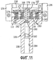
Фиг. 11 представляет собой сечение части узла каретки и узла корпуса, показывающее пружины, используемые для создания предварительной нагрузки на узел каретки.FIG. 11 is a sectional view of a portion of a carriage assembly and a housing assembly showing springs used to create a preload on a carriage assembly.
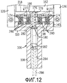
Фиг. 12 представляет собой сечение части узла каретки и узла корпуса, подобное сечению на фиг. 11, показывающее напряжение регулируемых пружин вследствие их предварительной нагрузки.FIG. 12 is a sectional view of a portion of a carriage assembly and a housing assembly similar to that of FIG. 11, showing the voltage of the adjustable springs due to their preload.
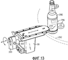
Фиг. 13 представляет собой изометрический вид, на котором показана регулируемая установка устройства для вращения стеклянных сосудов по настоящему изобретению на опорный элемент в положение для вращения стеклянного сосуда.FIG. 13 is an isometric view showing an adjustable installation of the apparatus for rotating glass vessels of the present invention on a support member in a position for rotating a glass vessel.
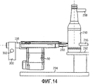
Фиг. 14 представляет собой вид сбоку на слегка наклоненное устройство для вращения стеклянных сосудов по настоящему изобретению с целью создания направленной вниз силы, действующей на стеклянный сосуд.FIG. 14 is a side view of a slightly inclined device for rotating glass vessels of the present invention in order to create a downward force acting on the glass vessel.
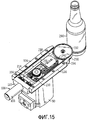
Фиг. 15 представляет собой изометрический вид устройства для вращения стеклянных сосудов по настоящему изобретению в положении вращения стеклянного сосуда, с которого для ясности снята крышка и верхняя главная пластина.FIG. 15 is an isometric view of the apparatus for rotating glass vessels of the present invention in a rotational position of a glass vessel from which the lid and the upper main plate have been removed.
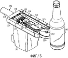
Фиг. 16 представляет собой изометрический вид, подобный виду по фиг. 15, но выполненный под другим углом.FIG. 16 is an isometric view similar to that of FIG. 15, but made from a different angle.
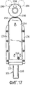
Фиг. 17 представляет собой вид сверху полностью собранного устройства для вращения стеклянных сосудов по настоящему изобретению в положении вращения стеклянного сосуда.FIG. 17 is a top view of a fully assembled apparatus for rotating glass vessels of the present invention in a rotation position of a glass vessel.
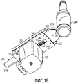
Фиг. 18 представляет собой изометрический вид, подобный виду по фиг. 17, но показывающий донную часть полностью собранного устройства для вращения стеклянных сосудов.FIG. 18 is an isometric view similar to that of FIG. 17, but showing the bottom of a fully assembled device for rotating glass vessels.
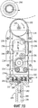
Фиг. 19 представляет собой вид сверху полностью собранного устройства для вращения стеклянных сосудов по настоящему изобретению, с которого для ясности снята крышка и верхняя главная пластина, показывающий положение ремня вращения изделий и колеса вращения изделий относительно положения стеклянного сосуда, вводимого в проверочную станцию.FIG. 19 is a top view of a fully assembled apparatus for rotating glass vessels of the present invention, from which, for clarity, the lid and upper main plate have been removed showing the position of the product rotation belt and the product rotation wheels relative to the position of the glass vessel introduced into the inspection station.
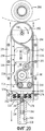
Фиг. 20 представляет собой вид сверху, подобный виду по фиг. 19, показывающий напряжение, вызванное в ремне вращения изделий начальной инерционностью стеклянного сосуда, «сопротивляющегося» вращению, а также перемещение узла каретки в направлении ремня вращения изделий, вызванное увеличенным натяжением ремня вращения изделий; иFIG. 20 is a plan view similar to that of FIG. 19, showing the stress caused in the product rotation belt by the initial inertia of the glass vessel "resisting" rotation, as well as the movement of the carriage assembly in the direction of the product rotation belt, caused by the increased tension of the product rotation belt; and
Фиг. 21 представляет собой вид сверху, подобный виду по фиг. 19 и 20, показывающий стеклянный сосуд, вращаемый ремнем вращения изделий и колесом вращения изделий на полной скорости, причем увеличенного натяжения ремня вращения изделий уже больше не существует, а узел каретки отошел назад, уменьшая давление, оказываемое на стеклянный сосуд.FIG. 21 is a plan view similar to that of FIG. 19 and 20, showing a glass vessel rotated by the belt of rotation of the products and the wheel of rotation of the products at full speed, and the increased tension of the belt of rotation of the products no longer exists, and the carriage assembly moved back, reducing the pressure exerted on the glass vessel.
ПОДРОБНОЕ ОПИСАНИЕ ПРИМЕРНЫХ ВАРИАНТОВ ОСУЩЕСТВЛЕНИЯDETAILED DESCRIPTION OF EXAMPLE EMBODIMENTS
Прежде чем обсуждать примерные варианты осуществления устройства для вращения стеклянных сосудов и способа согласно настоящему изобретению, полезно вкратце рассмотреть уже известные ранее устройства, которые используются для вращения приводного ролика, предназначенного для вращения стеклянных сосудов на проверочной станции, и для его позиционирования. Первый такой приводной механизм показан на фиг. 1 - он представляет собой устройство, которое установлено с возможностью вращения относительно горизонтальной оси таким образом, что разворачивается весь механизм, при этом приводной ролик 30 поджат пружиной для поворота в вертикальной плоскости в направлении приводимого во вращение сосуда 32. Стеклянный сосуд 32 опирается на опорную пластину 34, расположенную над верхней пластиной 36, причем с одной своей стороны стеклянный сосуд 32 поддерживается с возможностью поворота: в точке рядом с его дном - одной парой роликов 38, и в точке рядом с его верхней частью - второй парой роликов 40.Before discussing exemplary embodiments of the apparatus for rotating glass vessels and the method according to the present invention, it is useful to briefly consider previously known devices that are used to rotate the drive roller for rotating glass vessels in a test station and for positioning it. A first such drive mechanism is shown in FIG. 1 - it is a device that is mounted to rotate about a horizontal axis so that the entire mechanism is deployed, while the
Приводной ролик 30 установлен на оси 42, которая приводится во вращение электродвигателем 44, расположенным под верхней пластиной 36 на поворотном механизме 46, что позволяет электродвигателю 44 поворачиваться относительно горизонтальной оси таким образом, чтобы приводной ролик 30 при этом перемещался к стеклянному сосуду 32 или удалялся от него. Для смещения электродвигателя 44 к осевым наклоном так, чтобы приводной ролик 30 поджимался к стеклянному сосуду 32, используется пружина 48. Ограничительный механизм 50 используется для ограничения поворота при смещении электродвигателя 44 и тем самым, кроме того, - для ограничения расстояния, на которое может перемещаться приводной ролик 30 в направлении стеклянного сосуда 32 во избежание нанесения повреждения стеклянному сосуду 32. Как указано ранее, показанное на фиг. 1 приводное устройство, установленное в высокоскоростной линии проверки, является очень «жестким» по отношению к стеклянным сосудам 32, поскольку вследствие большой массы приводного узла оно ударяет наподобие молотка по стеклянным сосудам 32 и потенциально может повредить их.The
Второй ранее известный приводной механизм, используемый для приведения в действие и позиционирования приводного ролика, предназначенного для вращения стеклянных сосудов на проверочной станции, показан на фиг. 2 и 3 и представляет собой устройство, которое имеет приводной ролик 60, установленный с возможностью вращения относительно вертикальной оси таким образом, что этот приводной ролик 60 поджат пружиной в горизонтальной плоскости к приводимому сосуду 62. Стеклянный сосуд 62 опирается на опорную пластину 64, расположенную над верхней пластиной 66, причем стеклянный сосуд 62 поддерживается с возможностью поворота с одной его стороны: в точке рядом с его дном - одной парой роликов 68 и в точке рядом с его верхней частью - второй парой роликов 70.A second previously known drive mechanism used to drive and position a drive roller for rotating glass vessels at a test station is shown in FIG. 2 and 3 and is a device that has a
Под верхней пластиной 66 установлен электродвигатель 72, который с помощью приводного ремня 76 вращает вал 74. Вал 74 проходит вверх сквозь верхнюю пластину 66 и вращает второй приводной ремень 78, который вращает ось 80, на которой установлен приводной ролик 60. Электродвигатель 72 установлен неподвижно, но приводной ролик 60 установлен с возможностью поворотного смещения относительно вертикальной оси 82 вала 74 так, что он поворачивается в горизонтальной плоскости, таким образом, вызывая приближение приводного ролика 60 к стеклянному сосуду 62 и удаление от него. Для поджима приводного ролика 60, чтобы он перемещался относительно своей точки разворота, вынуждая таким образом этот приводной ролик 60 поджиматься к стеклянному сосуду 62, используется пружина 84. Как указано ранее, показанное на фиг. 2 и 3 приводное устройство, установленное в высокоскоростной линии проверки, не является столь «жестким» по отношению к стеклянным сосудам 62, как устройство, показанное на фиг. 1, но оно механически сложно, имеет значительную надежность, а также является дорогим в изготовлении.An
На фиг. 4 показана конструкция узла корпуса, используемого в устройстве для вращения стеклянных сосудов и в способе по настоящему изобретению. Узел 90 электродвигателя имеет плоскую по существу прямоугольную верхнюю часть 92 с четырьмя резьбовыми отверстиями 94, расположенными соответственно по четырем углам верхней части 92. Узел 90 электродвигателя имеет шкив 96 приводного ремня, установленный на конце вала электродвигателя и выступающий над верхней частью 92. Шкив 96 привода ремня является зубчатым шкивом, имеющим кольцевой буртик, выступающий наружу относительно зубьев по центральной линии шкива 96 приводного ремня. Как будет очевидно далее в связи с обсуждением фиг. 9, шкив 96 привода ремня выполнен с возможностью приема зубчатого ремня, имеющего продольно идущую канавку, прорезанную в зубьях зубчатого ремня по его центральной линии, которая предназначена для входа в нее буртика шкива 96 приводного ремня.In FIG. 4 shows the construction of a housing assembly used in a device for rotating glass vessels and in the method of the present invention. The
На верхней части 92 корпуса узла 90 электродвигателя установлена прямоугольная опорная пластина 98, имеющая некоторое количество выполненных в ней отверстий. Опорная пластина 98 имеет большое расположенное в ней круговое отверстие 100, предназначенное для приема шкива 96 привода ремня узла 90 электродвигателя. В пластине выполнены четыре зенкованных отверстия 102, расположенные вокруг отверстия 100 точно в такой же конфигурации, в которой расположены четыре резьбовых отверстия 94 в верхней части 92 корпуса узла 90 электродвигателя. Четыре винта 104 с плоскими головками вставляются соответственно в зенкованные отверстия 102 в опорной пластине 98 и затем входят в резьбовые отверстия 94 в верхней части 92 корпуса узла 90 электродвигателя для крепления опорной пластины 98 к узлу 90 электродвигателя.On the
Установочный держатель 106 состоит из цилиндрического сегмента 108, выступающего из середины прямоугольного бруска 110, имеющего фланец 112, идущий из нижней части этого прямоугольного бруска 110 со стороны, противоположной той, на которой находится цилиндрический сегмент 108. Прямо над фланцем 112 в прямоугольном бруске 110 прорезан паз 114, и в этом фланце 112 расположены три отстоящие друг от друга зенкованных отверстия 116 (на чертеже видно только одно из них). Дополнительные детали конструкции установочного держателя 106 будут описаны позже при описании фиг. 11 и 12. Ближний конец опорной пластины 98 содержит три резьбовых отверстия 118, расположенные на ней в конфигурации, идентичной конфигурации расположения отверстий 116 во фланце 112. Ближний конец опорной пластины 98 вставлен над фланцем 112 в паз 114 установочного держателя 106, и три винта 120 с плоскими головками вставляются соответственно в зенкованные отверстия 116 во фланце 112 и затем входят в резьбовые отверстия 118 в опорной пластине 98 для крепления опорной пластины 98 к установочному держателю 106.The mounting
На опорной пластине 98 рядом с ее левым краем, если смотреть со стороны ближнего конца опорной пластины 98, выполнены четыре отстоящие друг от друга резьбовых отверстия 122. На опорной пластине 98 рядом с ее правым краем, если смотреть со стороны ближнего конца опорной пластины 98, выполнены четыре отстоящие друг от друга резьбовых отверстия 124. Две эти группы резьбовых отверстий 122 и 124 будут использованы для установки направляющих по краям опорной пластины 98. Эти направляющие могут быть право- или левосторонними, что означает, что в зависимости от нужного направления вращения стеклянных сосудов на проверочной стации возможны две различные конфигурации этих направляющих.On the
В иллюстрируемом здесь варианте исполнения настоящего изобретения будем предполагать, что стеклянные сосуды будут вращаться против часовой стрелки при взгляде сверху. Таким образом, колесо вращения изделий (на фиг. 4 не показано), которое передает вращение стеклянным сосудам, будет вращаться по часовой стрелке, если смотреть сверху. Стеклянные сосуды будут входить в проверочную станцию, в которой установлено устройство для вращения стеклянных сосудов, слева, если смотреть от этого устройства для вращения стеклянных сосудов в направлении стеклянного сосуда в проверочной станции, и стеклянные сосуды будут выходить из проверочной станции справа, если смотреть в том же направлении.In the embodiment of the present invention illustrated here, we will assume that the glass vessels will rotate counterclockwise when viewed from above. Thus, the product rotation wheel (not shown in FIG. 4), which transmits rotation to glass vessels, will rotate clockwise when viewed from above. Glass vessels will enter the test station, in which the device for rotating glass vessels is installed, on the left, if you look from this device to rotate the glass vessels in the direction of the glass vessel in the test station, and the glass vessels will leave the test station on the right, if you look at that same direction.
На левой стороне опорной пластины 98 будет установлена передняя направляющая 126. Эта передняя направляющая 126 имеет нижний U-образный направляющий паз 128, выполненный на боковой стороне передней направляющей 126, направленной к правому краю опорной пластины 98, рядом с нижней стороной этой передней направляющей 126. Передняя направляющая 126 имеет также верхний U-образный направляющий паз 130, расположенный на той же стороне передней направляющей 126 рядом с верхней стороной этой передней направляющей 126. Передняя направляющая 126 имеет четыре зенкованных отверстия 132, расположенные на ней в конфигурации, идентичной конфигурации расположения четырех резьбовых отверстий 122, выполненных в опорной пластине 98 около ее левого края. Четыре винта 134 с цилиндрическими потайными головками вставляются соответственно в зенкованные отверстия 132 в передней направляющей 126 и затем входят в резьбовые отверстия 122 в опорной пластине 98 для крепления передней направляющей 126 на этой опорной пластине 98.A
На правой стороне опорной пластины 98 будет установлена задняя направляющая 136. Эта задняя направляющая 136 имеет нижний U-образный направляющий паз 138, выполненный на боковой стороне задней направляющей 136, направленной к передней направляющей 126 на левой стороне опорной пластины 98, рядом с нижней стороной этой задней направляющей 136. Задняя направляющая 126 имеет также верхний L-образный направляющий паз 140, расположенный на той же стороне задней направляющей 136 и открытый к верхней стороне этой задней направляющей 136. Задняя направляющая 136 имеет четыре зенкованных отверстия 142, расположенные на ней в конфигурации, идентичной конфигурации расположения четырех резьбовых отверстий 124, выполненных в опорной пластине 98 около ее правого края. Четыре винта 134 с цилиндрическими потайными головками вставляются соответственно в зенкованные отверстия 142 в задней направляющей 136 и затем входят в резьбовые отверстия 124 в опорной пластине 98 для крепления задней направляющей 136 на этой опорной пластине 98. И передняя направляющая 126, и задняя направляющая 136 могут быть выполнены из полимерного материала для уменьшения ударных сил, испытываемых устройством вращения стеклянных сосудов во время его работы.A
Сразу же отметим, что нижний U-образный направляющий паз 128 в передней направляющей 126 и нижний U-образный направляющий паз 138 в задней направляющей 136 выставлены между собой таким образом, что определяют плоскость, которая является параллельной и удалена от плоскости, определенной верхней поверхностью опорной пластины 98. Подобным же образом верхний U-образный направляющий паз 130 в передней направляющей 126 и верхний L-образный направляющий паз 140 в задней направляющей 136 также соответственно выставлены между собой таким образом, что определяют плоскость, которая является параллельной плоскости, определенной верхней поверхностью опорной пластины 98, и удалена от нее. Кроме того, в опорной пластине 98 между круговым отверстием 100 и дальним концом опорной пластины 98 есть отверстие 146 для доступа, назначение которой станет ясным далее в связи с описанием фиг. 5.Immediately, note that the lower
В опорной пластине 98 между круговым отверстием 100 и отверстием 146 для доступа выполнены два зенкованных отверстия 148 и 150. Эти зенкованные отверстия 148 и 150 расположены по противоположным сторонам относительно центральной линии опорной пластины 98, и в данном варианте осуществления изобретения будет использовано лишь одно из них. В рассматриваемом здесь примере, в котором стеклянные сосуды будут вращаться против часовой стрелки, если смотреть сверху, будет использовано отверстие 148, которое расположено рядом с правым краем опорной пластины 98. Сверху на опорной пластине 98 установлена опора 152 для шкива - с использованием винта с плоской головкой, идущего вверх сквозь зенкованное отверстие 148 и ввернутого в нижнюю часть этой опоры 152 для шкива.Two
На фиг. 5 показана конструкция узла каретки, используемого в устройстве для вращения стеклянных сосудов и в способе по настоящему изобретению, который будет установлен на узле корпуса, показанном на фиг. 4. Узел каретки построен на нижней главной пластине 160 и удаленной от нее верхней главной пластине 162. Когда узел каретки установлен на узле корпуса, боковые кромки нижней главной пластины 160 будут приняты нижним U-образным направляющим пазом 128 в передней направляющей 126 и нижним U-образным направляющим пазом 138 в задней направляющей 136, а боковые кромки верхней главной пластины 162 будут приняты верхним U-образным направляющим пазом 130 в передней направляющей 126 и верхним L-образным направляющим пазом 140 в задней направляющей 136.In FIG. 5 shows the construction of the carriage assembly used in the apparatus for rotating glass vessels and in the method of the present invention, which will be mounted on the housing assembly shown in FIG. 4. The carriage assembly is built on the lower
Нижняя главная пластина 160 имеет четыре зенкованных отверстия 164, которые расположены на удалении друг от друга около ближнего края нижней главной пластины 160. Задний прямоугольный разделительный брусок 166 имеет четыре резьбовых отверстия 168, расположенные в нем в конфигурации, идентичной конфигурации расположения четырех зенкованных отверстий 164 в нижней главной пластине 160. Четыре винта 170 с плоскими головками вставляются соответственно в зенкованные отверстия 164 в нижней главной пластине 160 и затем входят в резьбовые отверстия 168 в заднем разделительном бруске 166 для крепления заднего прямоугольного бруска 166 на нижней главной пластине 160.The lower
Задний разделительный брусок 166 имеет четыре цилиндрических углубления 172, расположенных на его удаленной стороне, с четырьмя пружинами сжатия 174, причем один конец каждой из пружин введен в соответствующее одно из цилиндрических углублений 172. По центру между цилиндрическими углублениями 172 расположено резьбовое отверстие 176, в которое ввинчен один конец резьбового штыря 178. На резьбовом штыре 178 расположена эластомерная шайба 180, а также цилиндрическая гайка 182 регулировки предварительной нагрузки, имеющая с одной из своих сторон резьбовое отверстие, а с другой стороны - шестигранное углубление под головку шестигранного гаечного ключа, причем противоположная сторона своим резьбовым концом навернута на резьбовой штырь 178. Использование гайки 182 регулировки предварительной нагрузки для регулировки предварительной нагрузки пружин сжатия 174 станет ясно далее из описания фиг. 11 и 12.The
На верхней стороне заднего разделительного бруска 166 на удалении от резьбовых отверстий 168 находятся два резьбовых отверстия 184. Эти резьбовые отверстия 184 расположены по противоположным сторонам относительно центральной линии нижней главной пластины 160 и заднего разделительного бруска 166. Использовано будет только одно из резьбовых отверстий 184, которое расположено ближе к правому краю нижней главной пластины 160 и заднего разделительного блока 166, если смотреть с ближнего конца нижней главной пластины 160 на дальний конец нижней главной пластины 160, причем то из резьбовых отверстий 184, которое будет использовано, зависит от направления, в котором устройство для вращения стеклянных сосудов будет вращать стеклянные сосуды.On the upper side of the
В нижней главной пластине 160 и в верхней главной пластине 162 рядом с их соответствующими удаленными концами находятся соответственно центрально расположенные соответствующие друг другу отверстия 186 и 188. Эти отверстия 186 и 188 используются для удерживания соответствующих концов опорной оси 190, относительно которой будет вращаться колесо 192 вращения изделий. Колесо 192 вращения изделий является зубчатым с кольцевым буртиком 194, который выступает наружу относительно зубьев по центральной линии колеса 192 вращения изделий. Колесо 192 вращения изделий может быть выполнено из эластомерного материала, например, такого как полиуретан.In the lower
Нижняя главная пластина 160 имеет большое прямоугольное отверстие 196, расположенное на этой пластине ближе к ее ближнему концу, чем к дальнему. Это прямоугольное отверстие 196 предназначено для того, чтобы сквозь него свободно проходили шкив 96 приводного ремня, а также холостой шкив 156 узла корпуса, показанного на фиг. 4, и является достаточно большим, чтобы нижнюю главную пластину 160 можно было перевернуть относительно ее центральной линии, если узел каретки надо будет изменить для изменения направления вращения стеклянных сосудов на противоположное. Верхняя главная пластина 162 также имеет большое прямоугольное отверстие 198, расположенное на этой пластине в соответствии с расположением прямоугольного отверстия 196 на нижней главной пластине 160.The lower
На нижней главной пластине 160 недалеко от прямоугольного отверстия 196 расположены два отверстия 200 и 202. Отверстие 200 находится рядом с правым краем нижней главной пластины 160, а отверстие 202 находится сбоку от отверстия 196 прямо по центральной линии нижней главной пластины 160. На верхней главной пластине 162, в местах, соответствующих расположению отверстий 200 и 202 на нижней главной пластине 160, находятся два отверстия 204 и 206.Two
Отверстия 200 и 204 используются для удержания соответствующих концов опорной оси 208, на которой будет вращаться холостой шкив 210. Отверстия 202 и 206 используются для удержания соответствующих концов опорной оси 212, на которой будет вращаться холостой шкив 214. Как таковые, холостой шкив 210 и холостой шкив 214 выполнены с возможностью приема зубчатого ремня, имеющего продольно идущую канавку, прорезанную в зубьях зубчатого ремня по его центральной линии, которая предназначена для входа в нее буртиков холостых шкивов 210 и 214.
На нижней главной пластине 160, около ее левого края имеются четыре отстоящие друг от друга зенкованных отверстия 216. По левой стороне нижней главной пластины 160 будет установлен разделительный брусок 218. Этот разделительный брусок 218 имеет четыре резьбовых отверстия 220, расположенные на нем в конфигурации, идентичной конфигурации расположения четырех зенкованных отверстий 216, выполненных в нижней главной пластине 160 около ее левой стороны. Четыре винта 222 с плоскими головками вставляются соответственно в зенкованные отверстия 216 в нижней главной пластине 160 и затем входят в резьбовые отверстия 220 разделительного бруска 218 для крепления этого разделительного бруска 218 на нижней главной пластине 160. Хотя на верхней главной пластине 162 показаны четыре отверстия, расположенные на ней в конфигурации, идентичной конфигурации четырех зенкованных отверстий 216 в нижней главной пластине 160, винты 222 с плоскими головками не проходят в верхнюю главную пластину 162, поскольку желательно, чтобы верхнюю главную пластину 162 можно было бы снимать с узла каретки, когда этот узел каретки устанавливается на узел корпуса.On the lower
На нижней главной пластине 160 на удалении от прямоугольного отверстия 196 выполнены две щели 224 и 226, расположенные по разные стороны от центральной линии нижней главной пластины 160. В данном варианте осуществления будет использована только одна из щелей 224 и 226. В рассматриваемом здесь примере, в котором стеклянные сосуды будут вращаться против часовой стрелки, если смотреть сверху, будет использоваться щель 224, которая ближе к левому краю нижней главной пластины 160. Эта щель 224 будет использоваться совместно с узлом натяжного устройства ремня, состоящим из трех частей.On the lower
Узел натяжения ремня имеет пластину 228 натяжного устройства с продольной щелью 230, которая ориентирована в том же самом направлении, что и щель 224 в нижней главной пластине 160. Справа от щели 230 около ближнего края пластины 228 натяжного устройства имеется круговое углубление 232, а слева от щели 230 около ближнего края пластины 228 натяжного устройства имеется другое круговое углубление 234. Держатель 236 натяжного устройства имеет центрально расположенную стенку 238, идущую от него вниз, и эта стенка 238 будет накладываться на продольную щель 230 в пластине 228 натяжного устройства. С правой стороны нижней части держателя 236 натяжного устройства идет вниз цилиндрическая опорная ось 240, которая, когда держатель 236 натяжного устройства располагается на пластине 228 натяжного устройства, входит в круговое углубление 232 в пластине 228 натяжного устройства. Другая цилиндрическая опорная ось, которая на чертеже не видна, идет вниз с правой стороны нижней части держателя 236 натяжного устройства, и когда держатель 236 натяжного устройства располагается на пластине 228 натяжного устройства, она входит в круговое углубление 234 в пластине 228 натяжного устройства.The belt tensioner has a
На опорной оси 240 держателя 236 натяжного устройства установлен с возможностью вращения холостой шкив 242, который удерживается нижней частью опорной оси 240, заходящей в круговое углубление 232, когда держатель 236 натяжного устройства располагается на пластине 228 натяжного устройства. Через держатель 236 натяжного устройства внутрь стенки 238 проходят резьбовые отверстия 244. Сквозь щель 224 в нижней главной пластине 160 и сквозь продольную щель 230 в пластине 228 натяжного устройства проходят два винта 246 с соответственно надетыми на них шайбами 248, которые заходят в два из резьбовых отверстий 244. Понятно, что продольное положение узла натяжного устройства ремня, а значит, и холостого шкива 242 на нижней главной пластине 160 является регулируемым.The
Ремень 250 вращения изделий показан на чертеже в таком виде, который он будет иметь, будучи вставленным в узел каретки с показанной на чертеже конфигурацией (при которой стеклянные сосуды вращаются против часовой стрелки, если смотреть сверху). Установка ремня на различные элементы будет описана далее в связи с обсуждением фиг. 7. Верхняя главная пластина 162 будет установлена над нижней главной пластиной 160 таким образом, что ближний конец верхней главной пластины 162 наложится на задний разделительный брусок 166. В этом положении отверстие 252 в верхней главной пластине 162 наложится на резьбовое отверстие 184 в заднем разделительном бруске 166. Верхние части опорной оси 190, опорной оси 208 и опорной оси 212 пройдут сквозь отверстия 188, отверстие 204 и отверстие 206 в верхней главной пластине 162.The
На верхнем конце каждой из осей - опорной оси 190, опорной оси 208 и опорной оси 212 имеются направляющие зазоры, выполненные в виде кольцевых канавок. Открытые части верхней главной пластины 162 будут закрыты крышкой 254, при этом направляющие отверстия 256, 258 и 260 в крышке 254 расположены в местах, соответствующих положению отверстий 188, 204 и 206 в верхней главной пластине 162. Таким образом, направляющие зазоры на верхних концах опорной оси 190, опорной оси 208 и опорной оси 212 входят в направляющие отверстия 256, 258 и 260 и запирают крышку 254 по месту сверху верхней главной пластины 162. Когда крышка 254 запирается по месту на верхней главной пластине 162, отверстие 262 в крышке 254 накладывается на отверстие 252 в верхней главной пластине 162. При этом винт 264 проходит сквозь отверстие 262 в крышке 254, сквозь отверстие 252 в верхней главной пластине 162 и заходит в резьбовое отверстие 184 в заднем разделительном бруске 166.At the upper end of each of the axes - the
Теперь обратимся к фиг. 6, на которой с левой стороны показан собранный узел корпуса, а с правой стороны показан почти собранный узел каретки. Но для облегчения установки узла каретки на узел корпуса передняя направляющая 126 и установочный держатель 106 сняты с опорной пластины 98 узла основания. На нижней главной пластине 160 с резьбового штыря 178 сняты также эластомерная шайба 180 и гайка 182 регулировки предварительной нагрузки.Turning now to FIG. 6, on which the assembled housing unit is shown on the left side, and the almost assembled carriage assembly is shown on the right side. But to facilitate the installation of the carriage assembly on the housing assembly, the
Нижняя главная пластина 160 узла каретки может быть опущена на опорную пластину 98 узла корпуса, при этом шкив 96 привода ремня и холостой шкив 156 узла корпуса пройдут сквозь прямоугольное отверстие 196 в нижней главной пластине 160. После этого передняя направляющая 126 и задняя направляющая 136 могут быть установлены на свое место на опорной пластине 98, при этом левый край нижней главной пластины 160 находится в нижнем U-образном направляющем пазу 128 в передней направляющей 126, а правая кромка нижней главной пластине 160 находится в верхнем L-образном направляющем пазу 140 в задней направляющей 136.The lower
Установочный держатель 106 может быть возвращен на свое место на опорной пластине 98, при этом резьбовой штырь 178 проходит в цилиндрический сегмент 108 установочного держателя 106 (конфигурация внутренней части цилиндрического сегмента 108 будет описана далее при обсуждении фиг. 11 и 12). После этого каждый из элементов - передняя направляющая 126, задняя направляющая 136 и установочный держатель 106 крепится к опорной пластине 98 с использованием соответствующего крепежа, удерживающего их на своих соответствующих местах. Затем можно вернуть на свои места на резьбовом штыре 178, который расположен в цилиндрическом сегменте 108, эластомерную шайбу 180 и гайку 182 регулировки предварительной нагрузки.The mounting
Далее на фиг. 7 показана установка ремня 250 вращения изделий. Установка ремня 250 вращения изделий может быть упрощена, если с узла каретки снять узел натяжного устройства ремня (который включает в себя пластину 228 натяжного устройства, держатель 236 натяжного устройства и холостой шкив 242), что выполняется удалением двух винтов 246 и их шайб 248. Как отмечалось выше, колесо 192 вращения изделий, холостой шкив 210 и холостой шкив 214, которые будут расположены внутри ремня 250 вращения изделий, являются зубчатыми с кольцевыми буртиками, которые выступают наружу относительно зубьев по центральной линии. Холостой шкив 156 и холостой шкив 242, которые будут расположены с внешней стороны ремня 250 вращения изделий, не являются зубчатыми.Further in FIG. 7 shows the installation of a
Рассмотрим вкратце фиг. 8, на которой показано частичное сечение колеса 192 вращения изделий с надетым на него ремнем 250 вращения изделий. Колесо 192 вращения изделий установлено на опорной оси 190 с подшипником 270. На фиг. 9 - в дополнение к фиг. 8 - часть ремня 250 вращения изделий показана более подробно. Ремень 250 вращения изделий имеет зубья 272, в которых прорезан паз 274, идущий в продольном направлении по центральной линии этого ремня 250 вращения изделий.Let us briefly consider FIG. 8, which shows a partial cross-section of a
Зубья 272 могут быть выполнены из неопрена, а ремень 250 вращения изделий имеет расположенные внутри его армирующие волокна, которые могут быть выполнены из фибергласса или из пара-арамидного синтетического волокна, такого как материал, продаваемый компанией DuPont под торговой маркой КЕВЛАР. Со стороны, противоположной относительно зубьев 272, ремень 250 вращения изделий имеет покрывающий материал 278, то есть поверхность, которая будет контактировать со стеклянными сосудами и вращать их. Этот покрывающий материал 278 может быть эластичным материалом с высоким коэффициентом трения, таким как неопрен, белая резина, немаркировочная резина или тому подобный материал, который обеспечивал бы хороший поверхностный контакт со стеклянными сосудами. Ремень 250 вращения изделий для максимального увеличения своего срока службы должен иметь бесшовную конструкцию.The
Как также показано на фиг. 7, ремень 250 вращения изделий установлен таким образом, что зубья 272 входят в зацепление с колесом 192 вращения изделий, со шкивом 96 привода ремня, с холостым шкивом 210, а также с холостым шкивом 214, а задняя сторона ремня 250 вращения изделий опирается на холостой шкив 156 и холостой шкив 242. Продольное положение узла натяжного устройства ремня (который включает пластину 228 натяжного устройства, держатель 236 натяжного устройства, а также холостой шкив 242) может регулироваться для обеспечения должного натяжения ремня 250 вращения изделий, после чего производится затяжка винтов 246 для крепления узла натяжного устройства по месту.As also shown in FIG. 7, the
Теперь вместе с фиг. 7 рассмотрим фиг. 10, на которой показана установка верхней главной пластины 162 и крышки 254 на узел каретки и узел основания. Левый край верхней главной пластины 162 (на фиг. 10 это - правый край, показанный со стороны дальнего конца пластины) вставлен в верхний U-образный направляющий паз 130 в передней направляющей 126 узла основания. После этого правый край верхней главной пластины 162 (на фиг. 10 это - левый край, показанный со стороны дальнего конца пластины) опускается на верхний L-образный направляющий паз 140 в задней направляющей 136 узла основания. Как только он опустится, верхние концы опорной оси 190, опорной оси 208 и опорной оси 212 должным образом войдут в эту пластину и войдут соответственно в отверстие 188, отверстие 204 и в отверстие 206 в главной пластине 162.Now with FIG. 7 consider FIG. 10, which shows the installation of the upper
После этого на узел каретки опускается крышка 254, при этом верхние концы каждой из осей - опорной оси 190, опорной оси 208 и опорной оси 212 соответственно войдут в части 256, 258 и 260 с большим диаметром. Теперь крышка 254 может быть сдвинута в направлении удаления, при этом кольцевые канавки на верхних концах опорной оси 190, опорной оси 208 и опорной оси 212 соответственно войдут в части направляющих отверстий 256, 258 и 260 с меньшим диаметром, тем самым удерживая крышку 254 на узле каретки. После этого крышка 254 запирается в этом положении вводом винта 264 в отверстие 262 в крышке 254, в отверстие 252 в верхней главной пластине 162 и завинчиванием его в резьбовое отверстие 184 в прямоугольном бруске 110.After that, the
Далее на фиг. 11 и 12 показаны конструкция и процесс регулировки усилия смещения узла каретки относительно узла основания. Как уже говорилось ранее при обсуждении фиг. 5, на ближней стороне заднего разделительного бруска 166 имеются четыре пружины сжатия 174, один из концов каждой из которых расположен в одном из четырех цилиндрических углублений 172. Прямоугольный брусок 110 также имеет четыре цилиндрических углубления 280, которые расположены на его ближней стороне, и которые отцентрированы относительно четырех цилиндрических углублений 172 заднего разделительного бруска 166, при этом второй конец каждой из четырех пружин сжатия 174 находится в одном из соответствующих цилиндрических углублений 280.Further in FIG. 11 and 12 show the design and the process of adjusting the bias force of the carriage assembly relative to the base assembly. As mentioned earlier in the discussion of FIG. 5, there are four compression springs 174 on the proximal side of the
В цилиндрическом элементе 108 установочного держателя 106 имеется проход, который проходит далее через прямоугольный брусок 110 установочного держателя 106. Этот проход состоит из двух частей, причем первый цилиндрический проход 282 меньшего диаметра проходит почти через весь прямоугольный брусок 110, а второй цилиндрический проход 284 большего диаметра проходит через остаток прямоугольного бруска 110 и через всю длину цилиндрического элемента 108. Резьбовой штырь 178, конец которого ввернут в резьбовое отверстие 176 заднего разделительного бруска 166, проходит через цилиндрический проход 282 и заходит далеко в цилиндрический проход 284.In the
Эластомерная шайба 180 и гайка 182 регулировки предварительной нагрузки вставлены в цилиндрический проход 284 и установлены на резьбовой штырь 178. Таким образом, с помощью инструмента 286 с шестигранной головкой гайку 182 регулировки предварительной нагрузки можно вращать, производя регулировку предварительного сжатия пружин сжатия 174. Тем самым можно изменять усилие, которое может оказывать на стеклянный сосуд устройство для вращения стеклянных сосудов, выполненное по настоящему изобретению.The
Когда на проверочной станции нет никакой стеклянной бутылки, пружины сжатия 174 будут вызывать перемещение узла каретки вперед до тех пор, пока эластомерная шайба 180 не дойдет до конца цилиндрического прохода 284 и не остановит ход узла каретки. Таким образом, гайка 182 регулировки предварительной нагрузки расположена так, чтобы ограничить ход узла каретки. По мере того как величина хода узла каретки уменьшается, пружины сжатия 174 получают более сильную предварительную нагрузку. Используя гайку 182 регулировки предварительной нагрузки и изменяя положение головки вращения на ее установочной стойке, можно управлять начальным контактным усилием между колесом 192 вращения изделий, рядом с которым имеется ремень 250 вращения изделий, и стеклянным сосудом 290, а также величиной хода, который будет иметь узел каретки при заходе стеклянного сосуда 290 на проверочную станцию во время его вращения и при выходе из нее. Контактное усилие и ход узла каретки должны быть отрегулированы таким образом, чтобы надежное вращение стеклянного сосуда 290 обеспечивалось при приложении минимальной силы и при использовании минимального хода.When there is no glass bottle at the test station, compression springs 174 will cause the carriage assembly to move forward until the
На фиг. 13 и 14 показана установка устройства вращения стеклянных сосудов по настоящему изобретению в производственную линию. Стеклянный сосуд 290 опирается на опорную пластину 292, расположенную над верхней пластиной 294, причем стеклянный сосуд 290 с одной его стороны поддерживается с возможностью поворота - в точке рядом с его дном - одной парой роликов 296, и в точке рядом с его верхней частью - второй парой роликов 298. Дальняя часть устройства для вращения стеклянных сосудов по настоящему изобретению вводится в контакт со стеклянным сосудом 290 с его стороны, противоположной роликам 296 и роликам 298. Понятно, что дальняя часть колеса 192 вращения изделий, рядом с которым имеется ремень 250 вращения изделий, будет касаться стеклянного сосуда 290 и вращать его.In FIG. 13 and 14 show the installation of the glass vessel rotation apparatus of the present invention in a production line. The
Устройство для вращения стеклянных сосудов по настоящему изобретению крепится на опорном элементе 300, который неподвижно закреплен с одного своего конца (на чертеже не показано). Другой конец опорного элемента 300 имеет конструкцию с разрезом, которая принимает в себя цилиндрический сегмент 108 установочного держателя 106 узла основания. Понятно, что устройство для вращения стеклянных сосудов по настоящему изобретению может как разворачиваться относительно оси цилиндрического сегмента 108, так и регулироваться в продольном направлении, тем самым перемещая дальнюю часть колеса 192 вращения изделий, рядом с которым имеется ремень 250 вращения изделий, ближе к стеклянному сосуду 290 или удаляя ее от него. Опорный элемент 300 имеет запорный болт 302, который может быть использован для запирания цилиндрического сегмента 108 и устройства вращения стеклянных сосудов по настоящему изобретению в нужном положении.The device for rotating glass vessels of the present invention is mounted on a
Специалистам в данной области техники будет понятно, что ни ролики 296, ни ролики 298, ни колесо 192 вращения изделий, рядом с которым имеется ремень 250 вращения изделий, не «работают» на удержание стеклянного сосуда 290 на опорной пластине 292 во время его вращения. Для того чтобы обеспечить постоянный контакт основания стеклянного сосуда 290 с опорной пластиной 292, желательно наклонить устройство для вращения стеклянных сосудов по настоящему изобретению таким образом, чтобы перемещение ремня 250 вращения изделий во время вращения им стеклянного сосуда 290 создавало действующую на этот сосуд силу, направленную вниз. Было установлено, что угол величиной не более двух градусов относительно горизонтальной плоскости является для этого вполне достаточным, при этом направленный вниз угол лежит в направлении перемещения ремня 250 вращения изделий относительно поверхности стеклянного сосуда 290.Those skilled in the art will understand that neither the
На фиг. 15-18 устройство для вращения стеклянных сосудов по настоящему изобретению показано в положении, в котором им производится вращение стеклянного сосуда 290. На фиг. 15 и 16 это устройство изображено со снятыми верхней главной пластиной 162 и крышкой 254, чтобы показать путь ремня 250 вращения изделий вокруг колеса 192 вращения изделий для вращения стеклянного сосуда 290, и особенно, чтобы показать работу узла натяжения ремня (который включает в себя пластину 228 натяжного устройства, держатель 236 натяжного устройства и холостой шкив 242), который поддерживает нужное натяжение ремня 250 вращения изделий. Кроме того, эти иллюстрации демонстрируют, как кольцевой буртик 194, присутствующий на колесе 192 вращения изделий, а также кольцевые буртики, выполненные соответственно по центральным линиям каждого из шкивов - шкива 96 привода ремня и холостых шкивов 210 и 212, взаимодействуют с пазом 274, идущим в продольном направлении по центральной линии ремня 250 вращения изделий между зубьями 272, для удержания ремня 250 на его опорной системе в нужном положении.In FIG. 15-18, the apparatus for rotating glass vessels of the present invention is shown in the position in which it rotates the
Фиг. 17 и 18 показывают предельные объемы пространства, которое занимает устройство для вращения стеклянных сосудов по настоящему изобретению, притом, что все устройство имеет ширину, немного большую, чем диаметр колеса 192 вращения изделий и толщина ремня 250 вращения изделий, особенно в той точке, в которой это устройство касается стеклянного сосуда 290 для его вращения. Поскольку устройство для вращения стеклянных сосудов по настоящему изобретению также является очень тонким, в значительной степени из-за того, что в конструкции устройства используется колесо 192 вращения изделий и ремень 250 вращения изделий, оно имеет очень небольшой размер в плане. На фиг. 18 показан также доступ к винтам 246 через отверстие доступа 146 в опорной пластине 98 для регулировки узла натяжения ремня (который включает в себя пластину 228 натяжного устройства, держатель 236 натяжного устройства и холостой шкив 242).FIG. 17 and 18 show the limiting volumes of the space occupied by the apparatus for rotating glass vessels of the present invention, while the entire apparatus has a width slightly larger than the diameter of the
Наконец, на фиг. 19-21 устройство для вращения стеклянных сосудов по настоящему изобретению показано в работе, вращающее стеклянный сосуд 290. На фиг. 19 стеклянный сосуд 290 показан в процессе поворота в положение проверки в проверочной станции, фиг. 20 показывает стеклянный сосуд 290, установленный в положение проверки в проверочной станции, но еще не разогнанный до полной скорости вращения, а фиг. 21 показывает стеклянный сосуд 290 в проверочной станции, имеющий полную скорость вращения.Finally, in FIG. 19-21, the apparatus for rotating glass vessels of the present invention is shown in operation, the rotating
На фиг. 19 можно видеть, что узел каретки подался вперед под действием пружин сжатия 174 до того его положения, при котором эластомерная шайба 180 достигла конца цилиндрического прохода 284 и остановила дальнейшее перемещение узла каретки. Можно заметить, что в этом положении ремень 250 вращения изделий и колесо 192 вращения изделий расположены внутри того положения, в котором стеклянный сосуд 290 будет находиться, когда он встанет в проверочную станцию.In FIG. 19, it can be seen that the carriage assembly moved forward under the action of compression springs 174 to the position where the
На фиг. 20 стеклянный сосуд 290 находится в проверочной станции, но еще не разогнан до полной скорости вращения, в первую очередь вследствие инерции стеклянного сосуда 290. Можно также видеть, что узел каретки немного втянулся назад под действием силы, оказываемой стеклянным сосудом 290 на ремень 250 вращения изделий и колесо 192 вращения изделий. Пружины сжатия 174 побуждают узел каретки, включая центральную часть колеса 192 вращения изделий и часть идущего вокруг него ремня 250 вращения изделий, к перемещению вперед до касания со стеклянным сосудом 290.In FIG. 20, the
По мере того как ремень 250 вращения изделий начинает вызывать вращение стеклянного сосуда 290 (но стеклянный сосуд 290 еще не вращается с полной скоростью), часть ремня 250 вращения изделий, идущая от колеса 192 вращения изделий вокруг холостых шкивов 210 и 214 и затем - к шкиву 96 привода ремня, нагружается все более интенсивно, увеличивая натяжение этой части ремня 250 вращения изделий. Увеличенное натяжение ремня 250 вращения изделий теперь тянет только тот отрезок этого приводного ремня, который может перемещаться, отрезок между холостым шкивом 214 (установлен на нижней главной пластине 160 узла каретки) и шкивом 96 привода ремня (установлен на узле 90 электродвигателя узла основания) тянет узел каретки в направлении удаления, вызывая прилегание ремня 250 вращения изделий и колеса 192 вращения изделий к стеклянному сосуду 290 с большим усилием.As the
По мере того как скорость стеклянного сосуда 290 приближается к конечной скорости вращения, натяжение в ремне 250 вращения изделий падает, оставляя пружины сжатия 174 как единственную силу, побуждающую узел каретки к перемещению в направлении изделия. Этот эффект серводействия данной геометрии ремня 250 вращения изделий позволяет устройству вращения стеклянных сосудов работать при более низких средневзвешенных во времени контактных усилиях, действующих на стеклянный сосуд 290 (что, конечно, увеличит срок службы компонентов устройства для вращения стеклянных сосудов по настоящему изобретению).As the speed of the
Из вышеизложенного подробного описания примерных вариантов осуществления настоящего изобретения может стать понятным, что оно показывает принцип устройства для вращения стеклянных сосудов, которое является в высшей степени компактным, что позволяет ему занимать минимальный объем в зоне около вращаемого стеклянного сосуда, оставляя, тем самым, максимально возможное пространство для проверочной аппаратуры. Несмотря на компактные размеры устройства для вращения стеклянных сосудов по настоящему изобретению, оно способно сообщать стеклянному сосуду достаточный вращающий момент для его быстрого ускорения, чтобы минимизировать время, необходимое для проверки каждого стеклянного сосуда. Устройство для вращения стеклянных сосудов по настоящему изобретению представляет в высокой степени податливую поверхность привода и, кроме того, демонстрирует повышенную способность быстрого «схватывания» внешней стенки стеклянного сосуда, что позволяет быстро преодолеть его инерционность и раскрутить его до нужной скорости.From the foregoing detailed description of exemplary embodiments of the present invention, it can be understood that it shows the principle of a device for rotating glass vessels, which is extremely compact, which allows it to occupy a minimum volume in the region near the rotating glass vessel, thereby leaving as much as possible space for test equipment. Despite the compact size of the device for rotating glass vessels of the present invention, it is able to provide the glass vessel with sufficient torque to accelerate it quickly to minimize the time required to inspect each glass vessel. The device for rotating glass vessels of the present invention represents a highly pliable drive surface and, in addition, exhibits an increased ability to quickly “set” the outer wall of the glass vessel, which allows it to quickly overcome its inertia and untwist it to the desired speed.
Устройство для вращения стеклянных сосудов по настоящему изобретению характеризуется низкой степенью ударного воздействия на стеклянные сосуды и обладает уникальной способностью быстрого перемещения для контакта со стеклянным сосудом без его повреждения и без повреждения им. Устройство для вращения стеклянных сосудов по настоящему изобретению способно также создавать действующую на этот стеклянный сосуд направленную вниз силу и тем самым прижимать его вниз во время его вращения с высокой скоростью. Устройство для вращения стеклянных сосудов по настоящему изобретению представляет собой жесткую механическую конструкцию, обладающую высокой надежностью, исключающую какие-либо производственные потери, обусловленные его выходом из строя.The device for rotating glass vessels of the present invention is characterized by a low degree of impact on glass vessels and has a unique ability to quickly move to contact the glass vessel without damaging it and without damaging it. The device for rotating glass vessels of the present invention is also capable of creating a downward force acting on the glass vessel and thereby pressing it down during its rotation at high speed. The device for rotating glass vessels of the present invention is a rigid mechanical structure with high reliability, eliminating any production losses due to its failure.
Устройство для вращения стеклянных сосудов по настоящему изобретению представляет собой такую конструкцию, которая является прочной, имеет длительный срок службы и имеет такие конструктивные характеристики, которые позволяют производить ее быстрое техническое обслуживание, кроме того, в течение всего срока службы оно потребует лишь относительно нечастого технического обслуживания со стороны пользователя.The device for rotating glass vessels of the present invention is such a structure that is durable, has a long service life and has such structural characteristics that allow its quick maintenance, in addition, during the entire service life it will require only relatively infrequent maintenance by the user.
Конструкция устройства для вращения стеклянных сосудов по настоящему изобретению является, кроме того, недорогой, что увеличит его коммерческую привлекательность и тем самым обеспечит ему максимально возможный рынок. Наконец, все вышеупомянутые преимущества и цели устройства для вращения стеклянных сосудов по настоящему изобретению достигнуты без внесения в него каких-либо существенных относительных недостатков.The design of the device for rotating glass vessels of the present invention is, in addition, inexpensive, which will increase its commercial attractiveness and thereby provide it with the maximum possible market. Finally, all of the above advantages and objectives of the apparatus for rotating glass vessels of the present invention are achieved without introducing any significant relative disadvantages.
Хотя приведенное выше описание устройства для вращения стеклянных сосудов и способа по настоящему изобретению было показано и описано со ссылками на конкретные варианты его осуществление и применения, оно было представлено с целью иллюстрации и описания, при этом не подразумевается, что оно является исчерпывающим или ограничивает данное изобретение раскрытыми здесь конкретными вариантами его осуществления и применения. Специалистам в данной области техники будут очевидны различные замены, модификации, изменения или переделки, которые можно было бы внести в данное изобретение, как оно здесь описано, не отклоняясь при этом от сущности или объема патентных притязаний настоящего изобретения. Конкретные варианты осуществления и применения настоящего изобретения были выбраны и описаны для того, чтобы дать наилучшую иллюстрацию принципов изобретения и его практического использования, чтобы тем самым предоставить возможность специалистам в данной области техники, применить настоящее изобретение в его различных вариантах осуществлениях и с его различными модификациями, какие могут быть нужны для задуманного его конкретного использования. Все такие замены, модификации, изменения и переделки должны рассматриваться как соответствующие объему патентных притязаний настоящего изобретения, определенному приложенными пунктами формулы изобретения, истолкованными в соответствии с той широтой, на которую они достоверно, законно и справедливо имеют право.Although the above description of the apparatus for rotating glass vessels and the method of the present invention has been shown and described with reference to specific options for its implementation and application, it has been presented for the purpose of illustration and description, but it is not intended to be exhaustive or to limit the invention specific embodiments disclosed herein for its implementation and use. Various replacements, modifications, alterations or alterations that could be made to the invention as described herein, without deviating from the essence or scope of patent claims of the present invention, will be apparent to those skilled in the art. Specific embodiments and applications of the present invention have been selected and described in order to best illustrate the principles of the invention and its practical use, thereby enabling those skilled in the art to apply the present invention in its various embodiments and with various modifications thereof, which may be needed for its intended use. All such replacements, modifications, alterations and alterations should be construed as in accordance with the scope of the patent claims of the present invention defined by the attached claims, interpreted in accordance with the breadth to which they are reliably, lawfully and fairly entitled.
Claims (20)
элемент основания, предназначенный для установки в регулируемом неподвижном положении относительно проверочной станции со стороны стеклянного сосуда, находящегося в проверочной станции, напротив стороны стеклянного сосуда, удерживаемой роликами;
элемент каретки, установленный на упомянутом элементе основания с возможностью прямолинейного перемещения относительно элемента основания в направлении стеклянного сосуда, находящегося в проверочной станции, и от него, причем упомянутый элемент каретки имеет противоположные ближний и дальний концы, где упомянутый дальний конец является ближайшим к проверочной станции, и упомянутый ближний конец является наиболее удаленным от проверочной станции;
колесо вращения изделий, которое установлено с возможностью вращения на упомянутом элементе каретки около его упомянутого дальнего конца таким образом, что часть упомянутого колеса вращения изделий выдается наружу относительно находящегося рядом упомянутого дальнего конца упомянутого элемента каретки;
электродвигатель, имеющий шкив привода ремня, приводимый во вращение упомянутым электродвигателем; и
ремень вращения изделий, установленный на упомянутый шкив привода ремня и на упомянутое колесо вращения изделий, причем упомянутый электродвигатель тем самым приводит в движение как упомянутый ремень вращения изделий, так и упомянутое колесо вращения изделий, где упомянутый ремень вращения изделий выполнен с возможностью подтягивать весь элемент каретки в направлении к стеклянному сосуду при увеличении натяжения ремня;
при этом часть упомянутого ремня вращения изделий расположена на той части упомянутого колеса вращения изделий, которая выдается наружу относительно находящегося рядом упомянутого дальнего конца упомянутого элемента каретки, причем упомянутый ремень вращения изделий касается боковой стороны стеклянного сосуда, находящегося в проверочной станции, напротив стороны стеклянного сосуда, удерживаемой роликами, для вращения стеклянной бутыли.1. A device for rotating glass vessels, which are sequentially introduced step-by-step into and out of the inspection station holding the glass vessel to be inspected on the surface and the inspection station has rollers for holding the glass vessel in this inspection station for rotation side opposite to that side of the glass vessel, which should interact with said device for rotating glass vessels, while said device for rotating Lamellar vessels contains:
a base element for installation in an adjustable fixed position relative to the test station from the side of the glass vessel located in the test station, opposite the side of the glass vessel held by the rollers;
a carriage element mounted on said base element with the possibility of rectilinear movement relative to the base element in the direction of the glass vessel located in the test station, and from it, said carriage element having opposite proximal and distal ends, where said distal end is closest to the test station, and said proximal end is farthest from the test station;
a product rotation wheel that is rotatably mounted on said carriage element near its said distal end so that a part of said product rotation wheel protrudes outward relative to a neighboring far end of said carriage element;
an electric motor having a belt drive pulley driven into rotation by said electric motor; and
a product rotation belt mounted on said belt drive pulley and on said product rotation wheel, wherein said electric motor thereby drives both said product rotation belt and said product rotation wheel, where the belt of rotation of the products is made with the ability to pull the entire element of the carriage in the direction of the glass vessel with increasing belt tension;
wherein a part of said product rotation belt is located on that part of said product rotation wheel that extends outward relative to a neighboring said far end of said carriage element, said product rotation belt touching the side of the glass vessel located in the inspection station, opposite the side of the glass vessel, held by rollers to rotate the glass bottle.
установочный держатель, прикрепленный к опорному элементу с возможностью прямолинейного перемещения упомянутым элементом каретки в направлении проверочной станции и от нее, а также вращательного перемещения упомянутого элемента каретки относительно оси, параллельной оси упомянутого прямолинейного перемещения упомянутого элемента каретки в направлении проверочной станции и от нее.2. The device according to claim 1, wherein said base element comprises:
an installation holder attached to the support element with the possibility of rectilinear movement of said carriage element to and from the test station, as well as rotational movement of said carriage element relative to an axis parallel to the axis of said rectilinear movement of said carriage element to and from the test station.
направляющие для опоры упомянутого элемента каретки при его упомянутом прямолинейном перемещении, причем эти направляющие расположены по соответствующим сторонам упомянутого элемента каретки;
при этом упомянутые направляющие выполнены из полимерного материала для уменьшения ударных воздействий, испытываемых упомянутым устройством во время работы.4. The device according to claim 1, wherein said base element comprises:
guides for supporting said carriage element during said rectilinear movement, said guides being located on respective sides of said carriage element;
wherein said guides are made of a polymeric material to reduce the shock effects experienced by said device during operation.
смещающее устройство, которое прилагает к упомянутой каретке силу, принуждающую дальний конец каретки подаваться в направлении стеклянного сосуда, находящегося в проверочной станции.5. The device according to claim 1, further comprising:
a biasing device which exerts a force on said carriage forcing the distal end of the carriage to be fed in the direction of the glass vessel located in the test station.
установочный держатель, установленный на упомянутом элементе основания рядом с его концом, который дальше всего отстоит от проверочной станции;
задний разделительный брусок, установленный на упомянутом ближнем конце упомянутого узла каретки; и
по меньшей мере одну пружину, расположенную между упомянутым установочным держателем и упомянутым задним разделительным бруском.6. The device according to claim 5, in which said biasing device comprises:
an installation holder mounted on said base element near its end, which is farthest away from the test station;
a rear dividing bar mounted on said proximal end of said carriage assembly; and
at least one spring located between said mounting holder and said rear dividing bar.
в котором предусмотрен проходящий в продольном направлении паз, прорезанный в упомянутых зубьях на упомянутой внутренней поверхности упомянутого ремня вращения изделий по центральной линии этого ремня вращения изделий.10. The device according to p. 9, in which each of the elements - the aforementioned wheel of rotation of the products and the said belt drive pulley - has an annular flange that protrudes outward relative to the said teeth along the center line of each of them; and
which provides a longitudinally extending groove cut in said teeth on said inner surface of said product rotation belt along a center line of this product rotation belt.
по меньшей мере один холостой шкив, установленный на упомянутом элементе каретки рядом с его ближним концом, на котором установлен упомянутый ремень вращения изделий, причем упомянутый шкив привода ремня расположен ближе к упомянутому дальнему концу упомянутого узла каретки, чем упомянутый по меньшей мере один холостой шкив;
при этом, когда стеклянный сосуд, находящийся в проверочной станции, еще не раскручен упомянутым ремнем вращения изделий до полной скорости вращения, упомянутый электродвигатель будет управлять упомянутым шкивом привода ремня таким образом, чтобы увеличить натяжение той части упомянутого ремня вращения изделий, которая проходит от упомянутого колеса вращения изделий вокруг упомянутого по меньшей мере одного холостого шкива к упомянутому шкиву привода ремня, тем самым побуждая упомянутый узел каретки подаваться в направлении удаления, к стеклянному сосуду, находящемуся в проверочной станции.14. The device according to claim 1, further comprising:
at least one idle pulley mounted on said carriage element near its proximal end on which said product rotation belt is mounted, said belt drive pulley being located closer to said distal end of said carriage assembly than said at least one idle pulley;
however, when the glass vessel located in the test station is not yet untwisted by the said belt of rotation of the products to a full rotation speed, said electric motor will control the said belt drive pulley in such a way as to increase the tension of that part of the said belt of rotation of the products which extends from the said wheel rotation of the products around said at least one idle pulley to said belt drive pulley, thereby causing said carriage assembly to be fed in a direction of removal , A glass container in the inspection station.
узел натяжения ремня, включающий холостой шкив, который является регулируемым с целью регулировки натяжения упомянутого ремня вращения изделий.15. The device according to claim 1, additionally containing:
a belt tension unit including an idle pulley that is adjustable to adjust the tension of said belt of rotation of products.
ремня, упомянутый ремень вращения изделий и упомянутое колесо
вращения изделий расположены в одной горизонтальной плоскости.16. The device according to claim 1, wherein said drive pulley
a belt, said belt of rotation of articles and said wheel
product rotation are located in one horizontal plane.
по меньшей мере один холостой шкив, установленный на по меньшей мере одном из упомянутого узла основания и упомянутого узла каретки;
при этом упомянутое колесо вращения изделий, упомянутый шкив привода ремня и упомянутый по меньшей мере один холостой шкив, а также траектория упомянутого ремня вращения изделий соответственно расположены и сконфигурированы таким образом, что когда стеклянный сосуд, находящийся в проверочной станции, еще не раскручен упомянутым ремнем вращения изделий до полной скорости вращения, упомянутый электродвигатель будет управлять упомянутым шкивом привода ремня таким образом, чтобы увеличить натяжение той части упомянутого ремня вращения изделий, которая проходит от упомянутого колеса вращения изделий вокруг упомянутого по меньшей мере одного холостого шкива к упомянутому шкиву привода ремня, тем самым побуждая упомянутый узел каретки подаваться в направлении удаления, к стеклянному сосуду, находящемуся в проверочной станции.17. The device according to claim 1, additionally containing:
at least one idle pulley mounted on at least one of said base assembly and said carriage assembly;
wherein said product rotation wheel, said belt drive pulley and said at least one idle pulley, as well as the trajectory of said product rotation belt, are respectively arranged and configured so that when the glass vessel in the test station is not yet untwisted by said rotation belt products to full rotation speed, said electric motor will control said belt drive pulley so as to increase the tension of that part of said rotation belt Cereal products, which extends from said ware rotate wheel around said at least one idler pulley to said drive belt pulley, thereby urging said carriage assembly in a distal direction supplied to the glass container in the inspection station.
элемент основания, предназначенный для установки в регулируемом неподвижном положении относительно проверочной станции со стороны стеклянного сосуда, находящегося в проверочной станции, напротив стороны стеклянного сосуда, удерживаемой роликами;
элемент каретки, установленный на упомянутом элементе основания с возможностью прямолинейного перемещения относительно элемента основания в направлении стеклянного сосуда, находящегося в проверочной станции, и от него, причем упомянутый элемент каретки имеет противоположные ближний и дальний концы, где упомянутый дальний конец является ближайшим к проверочной станции, и упомянутый ближний конец является наиболее удаленным от проверочной станции;
одну или большее количество пружин смещения, которые прилагают к упомянутой каретке силу для побуждения ее дальнего конца подаваться в направлении стеклянного сосуда, находящегося в проверочной станции;
колесо вращения изделий, которое установлено с возможностью вращения на упомянутом элементе каретки около его упомянутого дальнего конца таким образом, что часть упомянутого колеса вращения изделий выдается наружу относительно находящегося рядом упомянутого дальнего конца упомянутого элемента каретки;
электродвигатель, имеющий шкив привода ремня, приводимый во вращение упомянутым электродвигателем, причем упомянутый электродвигатель установлен на упомянутом узле корпуса;
по меньшей мере один холостой шкив, установленный на упомянутом элементе каретки рядом с его упомянутым ближним концом; и
ремень вращения изделий, установленный на упомянутый шкив привода ремня, на упомянутое колесо вращения изделий и на упомянутый по меньшей мере один холостой шкив, посредством чего упомянутый электродвигатель приводит в движение как упомянутый ремень вращения изделий, так и упомянутое колесо вращения изделий;
при этом часть упомянутого ремня вращения изделий расположена на части упомянутого колеса вращения изделий, которая выдается наружу относительно находящегося рядом упомянутого дальнего конца упомянутого элемента каретки; причем упомянутый ремень вращения изделий касается боковой стороны стеклянного сосуда, находящегося в проверочной станции, напротив стороны стеклянного сосуда, удерживаемой роликами, для вращения стеклянного сосуда; и
при этом упомянутое колесо вращения изделий, упомянутый шкив привода ремня и упомянутый по меньшей мере один холостой шкив, а также траектория упомянутого ремня вращения изделий соответственно расположены и сконфигурированы таким образом, что когда стеклянный сосуд, находящийся в проверочной станции, еще не раскручен упомянутым ремнем вращения изделий до полной скорости вращения, упомянутый электродвигатель будет управлять упомянутым шкивом привода ремня таким образом, чтобы увеличить натяжение той части упомянутого ремня вращения изделий, которая проходит от упомянутого колеса вращения изделий вокруг упомянутого по меньшей мере одного холостого шкива к упомянутому шкиву привода ремня, тем самым побуждая упомянутый весь узел каретки подаваться в дистальном направлении к стеклянному сосуду, находящемуся в проверочной станции.18. A device for rotating glass vessels, which are sequentially introduced step-by-step into and out of the inspection station holding the glass vessel to be inspected on the surface, the inspection station having rollers for holding the glass vessel in this inspection station for rotation , from the side opposite to the side of the glass vessel, which must interact with said device for rotating glass vessels, wherein said device for rotating the stack All vessels contains:
a base element for installation in an adjustable fixed position relative to the test station from the side of the glass vessel located in the test station, opposite the side of the glass vessel held by the rollers;
a carriage element mounted on said base element with the possibility of rectilinear movement relative to the base element in the direction of the glass vessel located in the test station, and from it, said carriage element having opposite proximal and distal ends, where said distal end is closest to the test station, and said proximal end is farthest from the test station;
one or more bias springs that apply force to said carriage to cause its distal end to be fed in the direction of the glass vessel located in the test station;
a product rotation wheel that is rotatably mounted on said carriage element near its said distal end so that a part of said product rotation wheel protrudes outward relative to a neighboring far end of said carriage element;
an electric motor having a belt drive pulley driven into rotation by said electric motor, said electric motor being mounted on said housing unit;
at least one idle pulley mounted on said carriage element near its proximal end; and
a product rotation belt mounted on said belt drive pulley, on said product rotation wheel and on at least one idle pulley, whereby said electric motor drives both said product rotation belt and said product rotation wheel;
while part of the said belt of rotation of the products is located on the part of the said wheel of rotation of the products, which protrudes outward relative to the adjacent near the far end of said carriage element; wherein said product rotation belt touches the side of the glass vessel located in the test station, opposite the side of the glass vessel held by the rollers to rotate the glass vessel; and
wherein said product rotation wheel, said belt drive pulley and said at least one idle pulley, as well as the path of said product rotation belt, are respectively arranged and configured so that when a glass vessel located in a test station is not yet untwisted by said rotation belt products to full rotation speed, said electric motor will control said belt drive pulley so as to increase the tension of that part of said rotation belt Cereal products, which extends from said ware rotate wheel around said at least one idler pulley to said drive belt pulley, thereby urging said carriage assembly all fed in the distal direction toward the glass container in the inspection station.
элемент основания, предназначенный для установки в неподвижном положении относительно проверочной станции со стороны стеклянного сосуда, находящегося в проверочной станции, напротив стороны стеклянного сосуда, удерживаемой роликами; элемент каретки, установленный на упомянутом элементе основания с возможностью перемещения относительно элемента основания в направлении стеклянного сосуда, находящегося в проверочной станции, и от него, причем упомянутый элемент каретки имеет противоположные ближний и дальний концы;
колесо вращения изделий, которое установлено с возможностью вращения на упомянутом элементе каретки около его конца, ближайшего к проверочной станции;
электродвигатель, имеющий шкив привода ремня, приводимый во вращение упомянутым электродвигателем; и
ремень вращения изделий, установленный на упомянутый шкив привода ремня и на упомянутое колесо вращения изделий, посредством чего упомянутый электродвигатель приводит в движение как упомянутый ремень вращения изделий, так и упомянутое колесо вращения изделий;
при этом часть упомянутого ремня вращения изделий, расположенная на части упомянутого колеса вращения изделий, касается боковой стороны стеклянного сосуда, находящегося в проверочной станции, для вращения стеклянного сосуда.19. A device for rotating glass vessels in a test station, having rollers for holding the glass vessel for its rotation from the side opposite to that side of the glass vessel, which should interact with the said device, while the said device contains:
a base element for installation in a fixed position relative to the test station from the side of the glass vessel located in the test station, opposite the side of the glass vessel held by the rollers; a carriage element mounted on said base element with the possibility of movement relative to the base element in the direction of the glass vessel located in the test station, and from him, and the said carriage element has opposite near and far ends;
a product rotation wheel which is rotatably mounted on said carriage element near its end closest to the test station;
an electric motor having a belt drive pulley driven into rotation by said electric motor; and
a product rotation belt mounted on said belt drive pulley and on said product rotation wheel, whereby said electric motor drives both said product rotation belt and said product rotation wheel;
wherein a part of said product rotation belt located on a part of said product rotation wheel touches the side of the glass vessel located in the test station to rotate the glass vessel.
установку элемента основания в регулируемое неподвижное положение относительно проверочной станции со стороны стеклянного сосуда, находящегося в проверочной станции, напротив стороны стеклянного сосуда, удерживаемой роликами;
установку элемента каретки на упомянутом элементе основания с возможностью прямолинейного перемещения относительно элемента основания в направлении стеклянного сосуда, находящегося в проверочной станции, и от него, причем упомянутый элемент каретки имеет противоположные ближний и дальний концы, где упомянутый дальний конец является ближайшим к проверочной станции, а упомянутый ближний конец является наиболее удаленным от проверочной станции;
установку колеса вращения изделий с возможностью вращения на упомянутом элементе каретки около его упомянутого дальнего конца таким образом, что часть упомянутого колеса вращения изделий выдается наружу относительно находящегося рядом упомянутого дальнего конца упомянутого элемента каретки;
приведение во вращение шкива привода ремня
электродвигателем, и
установку ремня вращения изделий на упомянутый шкив привода ремня и на упомянутое колесо вращения изделий, посредством чего упомянутый электродвигатель приводит в движение как упомянутый ремень вращения изделий, так и упомянутое колесо вращения изделий, а ремень вращения изделий выполнен с возможностью подтягивать весь элемент каретки в направлении к стеклянному сосуду при увеличении натяжения ремня; при этом часть упомянутого ремня вращения изделий располагают на части упомянутого колеса вращения изделий, которая выдается наружу относительно находящегося рядом упомянутого дальнего конца упомянутого элемента каретки, и упомянутый ремень вращения изделий касается боковой стороны стеклянного сосуда, находящегося в проверочной станции, напротив стороны стеклянного сосуда, удерживаемой роликами, для вращения стеклянного сосуда. 20. The method of rotation of glass vessels, which are sequentially introduced step by step into a test station that holds the glass vessel to be checked on the surface in an upright position, and is removed from it, and the test station has rollers for holding the glass vessel for its rotation, from the side opposite to that side a glass vessel, which must interact with said device for rotating glass vessels, wherein said method for rotating glass vessels includes:
the installation of the base element in an adjustable stationary position relative to the test station from the side of the glass vessel located in the test station, opposite the side of the glass vessel held by the rollers;
installing a carriage element on said base element with the possibility of rectilinear movement relative to the base element in the direction of the glass vessel located in the test station, and from him, moreover, said carriage element has opposite near and far ends, where the said distal end is the closest to the test station, and said near end is farthest from the test station;
setting the wheel of rotation of the products to rotate on said carriage element near its said distal end so that a part of said wheel of rotation of the products protrudes outward relative to the adjacent far end of said carriage element;
bringing the belt pulley into rotation
electric motor, and
mounting the product rotation belt on said belt drive pulley and on said product rotation wheel, whereby said electric motor drives both said product rotation belt and said product rotation wheel, and the product rotation belt is configured to pull the entire carriage element toward a glass vessel with an increase in belt tension; wherein a part of said product rotation belt is arranged on a part of said product rotation wheel which extends outward relative to a neighboring said far end of said carriage element, and said product rotation belt touches a side of a glass vessel located in a test station, opposite the side of the glass vessel held by rollers, for rotation of a glass vessel.
Applications Claiming Priority (2)
| Application Number | Priority Date | Filing Date | Title |
|---|---|---|---|
| US12/253,951 | 2008-10-18 | ||
| US12/253,951 US8429989B2 (en) | 2008-10-18 | 2008-10-18 | Modular apparatus and method for rotating glass containers and the like |
Publications (2)
| Publication Number | Publication Date |
|---|---|
| RU2009138355A RU2009138355A (en) | 2011-04-27 |
| RU2507504C2 true RU2507504C2 (en) | 2014-02-20 |
Family
ID=41572326
Family Applications (1)
| Application Number | Title | Priority Date | Filing Date |
|---|---|---|---|
| RU2009138355/03A RU2507504C2 (en) | 2008-10-18 | 2009-10-16 | Modular device and method to rotate glass vessels and similar items |
Country Status (4)
| Country | Link |
|---|---|
| US (1) | US8429989B2 (en) |
| EP (1) | EP2177899B1 (en) |
| JP (1) | JP5500878B2 (en) |
| RU (1) | RU2507504C2 (en) |
Families Citing this family (8)
| Publication number | Priority date | Publication date | Assignee | Title |
|---|---|---|---|---|
| DE102011056609A1 (en) * | 2011-12-19 | 2013-06-20 | Schuler Pressen Gmbh | Device for transporting cylindrical containers |
| US8973733B2 (en) * | 2012-01-04 | 2015-03-10 | Douglas Machine Inc. | Article orienter and attendant orientation operations |
| CN103308527B (en) * | 2013-05-30 | 2015-02-11 | 屈桢深 | Detection method and detection system for foreign matters in infusion bottle |
| US9527163B2 (en) * | 2014-10-29 | 2016-12-27 | Provide Commerce, Inc. | Support apparatus |
| WO2016171197A1 (en) * | 2015-04-24 | 2016-10-27 | ニプロ株式会社 | Method for producing medical glass container, and fire blast device provided with rotator |
| EP3797883B1 (en) | 2019-09-27 | 2022-06-08 | SCHOTT Schweiz AG | Apparatus for inspecting a pharmaceutical container |
| EP3798621B1 (en) | 2019-09-27 | 2022-11-23 | SCHOTT Schweiz AG | Apparatus for inspecting a pharmaceutical container |
| EP3855174B1 (en) | 2020-01-23 | 2024-05-15 | SCHOTT Pharma Schweiz AG | Detection and characterization of defects in pharmaceutical cylindrical containers |
Citations (5)
| Publication number | Priority date | Publication date | Assignee | Title |
|---|---|---|---|---|
| RU2119657C1 (en) * | 1993-05-05 | 1998-09-27 | Бритиш Нуклеа Фюэлс ПЛС | Surface flaw detector |
| US6116404A (en) * | 1995-11-24 | 2000-09-12 | Heuft Systemtechnik Gmbh | Process and device for conveying containers past a device for inspecting the container bases |
| RU2213710C2 (en) * | 1998-06-17 | 2003-10-10 | Оуэнс-Броквэй Гласс Контейнер Инк. | Check of container neck by means of infra-red energy radiated by container bottom |
| RU2224241C2 (en) * | 1997-12-24 | 2004-02-20 | Оуэнс-Броквэй Гласс Контейнер Инк. | Method testing clear glass containers for presence of deviations of stresses and degree of transparency and facility for its implementation |
| US7010863B1 (en) * | 2004-01-26 | 2006-03-14 | Owens-Brockway Glass Container Inc. | Optical inspection apparatus and method for inspecting container lean |
Family Cites Families (32)
| Publication number | Priority date | Publication date | Assignee | Title |
|---|---|---|---|---|
| US3262561A (en) | 1964-06-15 | 1966-07-26 | Owens Illinois Inc | Inspecting and assorting glass containers |
| US3348049A (en) | 1964-12-31 | 1967-10-17 | Ball Brothers Res Corp | High speed ultraviolet thin spot detector |
| GB1155976A (en) | 1966-06-30 | 1969-06-25 | Arthur Terence Ranson | Glassware Inspection Apparatus. |
| US3410388A (en) * | 1967-02-03 | 1968-11-12 | Robert D. Hendrickson | Bottle handling apparatus |
| US3460669A (en) | 1967-07-31 | 1969-08-12 | Owens Illinois Inc | Container indexing and rotating |
| US3426884A (en) | 1967-08-15 | 1969-02-11 | Solar Eng & Equipment Co | Glass bottle handling apparatus |
| US3557950A (en) | 1968-09-24 | 1971-01-26 | Powers Manufacturing | Photo-electric crack detector for glass bottles |
| US3684089A (en) | 1970-09-21 | 1972-08-15 | Brockway Glass Co Inc | Container wall thickness detection |
| US3735855A (en) | 1970-12-28 | 1973-05-29 | Owens Illinois Inc | Container rotating apparatus |
| US3690456A (en) | 1971-06-25 | 1972-09-12 | Powers Manufacturing | Glass container crack detector |
| CH548599A (en) | 1972-01-19 | 1974-04-30 | Emhart Zuerich Sa | Crack testing station for the sorting line of a plant for the production of glass containers. |
| US4021122A (en) | 1973-01-02 | 1977-05-03 | Emhart Zurich S.A. | Glass container inspection machine |
| JPS5228432B2 (en) * | 1973-10-29 | 1977-07-26 | ||
| US3957154A (en) | 1974-01-29 | 1976-05-18 | Hitachi Shipbuilding And Engineering Co., Ltd. | Apparatus for rotating bottles |
| CH570912A5 (en) | 1974-03-11 | 1975-12-31 | Emhart Zuerich Sa | |
| US3991883A (en) | 1974-05-06 | 1976-11-16 | Powers Manufacturing Incorporated | Method and apparatus for identifying a bottle |
| US4323158A (en) | 1980-07-03 | 1982-04-06 | Wheaton Industries | Bottle neck finish inspection apparatus |
| JPS603542A (en) | 1983-06-21 | 1985-01-09 | Mitsubishi Electric Corp | Bottle inspecting device |
| US4653628A (en) | 1984-03-23 | 1987-03-31 | Emhart Industries, Inc. | Apparatus for orienting containers |
| US5028769A (en) | 1986-08-20 | 1991-07-02 | Emhart Industries, Inc. | Device for reading a mold code on a glass bottle |
| US4915237A (en) | 1986-09-11 | 1990-04-10 | Inex/Vistech Technologies, Inc. | Comprehensive container inspection system |
| US4786801A (en) | 1987-07-21 | 1988-11-22 | Emhart Industries Inc. | Finish Leak Detector having vertically movable light source |
| US4967070A (en) | 1989-07-19 | 1990-10-30 | Owens-Brockway Glass Container Inc. | Indentification of a molded container with its mold of origin |
| US5405015A (en) | 1993-08-11 | 1995-04-11 | Videojet Systems International, Inc. | System and method for seeking and presenting an area for reading with a vision system |
| EP0642995A1 (en) * | 1993-09-15 | 1995-03-15 | Emhart Glass Machinery Investments Inc. | Tapered container handler |
| JP3351910B2 (en) | 1994-09-01 | 2002-12-03 | エーザイ株式会社 | Vial bottle inspection method and equipment |
| US5608516A (en) | 1995-12-13 | 1997-03-04 | Emhart Glass Machinery Investments Inc. | Glass bottle inspection machine |
| DE19605133C2 (en) | 1996-02-13 | 2000-06-15 | Krones Ag | Inspection machine for vessels |
| US5823317A (en) | 1996-12-04 | 1998-10-20 | New England Machinery, Inc. | Apparatus for uniformly orientating articles |
| US5895911A (en) | 1998-01-22 | 1999-04-20 | Emhart Glass S.A. | Glass container body check detector |
| US6172355B1 (en) * | 1998-10-13 | 2001-01-09 | Owens-Brockway Glass Container Inc. | In-line inspection of containers |
| JP3062611U (en) * | 1999-03-31 | 1999-10-08 | 三ツ星ベルト株式会社 | Toothed belt |
-
2008
- 2008-10-18 US US12/253,951 patent/US8429989B2/en active Active
-
2009
- 2009-06-19 JP JP2009145977A patent/JP5500878B2/en not_active Expired - Fee Related
- 2009-10-13 EP EP09172944.2A patent/EP2177899B1/en active Active
- 2009-10-16 RU RU2009138355/03A patent/RU2507504C2/en active
Patent Citations (5)
| Publication number | Priority date | Publication date | Assignee | Title |
|---|---|---|---|---|
| RU2119657C1 (en) * | 1993-05-05 | 1998-09-27 | Бритиш Нуклеа Фюэлс ПЛС | Surface flaw detector |
| US6116404A (en) * | 1995-11-24 | 2000-09-12 | Heuft Systemtechnik Gmbh | Process and device for conveying containers past a device for inspecting the container bases |
| RU2224241C2 (en) * | 1997-12-24 | 2004-02-20 | Оуэнс-Броквэй Гласс Контейнер Инк. | Method testing clear glass containers for presence of deviations of stresses and degree of transparency and facility for its implementation |
| RU2213710C2 (en) * | 1998-06-17 | 2003-10-10 | Оуэнс-Броквэй Гласс Контейнер Инк. | Check of container neck by means of infra-red energy radiated by container bottom |
| US7010863B1 (en) * | 2004-01-26 | 2006-03-14 | Owens-Brockway Glass Container Inc. | Optical inspection apparatus and method for inspecting container lean |
Also Published As
| Publication number | Publication date |
|---|---|
| US8429989B2 (en) | 2013-04-30 |
| EP2177899A1 (en) | 2010-04-21 |
| JP5500878B2 (en) | 2014-05-21 |
| US20100095790A1 (en) | 2010-04-22 |
| EP2177899B1 (en) | 2015-01-21 |
| JP2010095386A (en) | 2010-04-30 |
| RU2009138355A (en) | 2011-04-27 |
Similar Documents
| Publication | Publication Date | Title |
|---|---|---|
| RU2507504C2 (en) | Modular device and method to rotate glass vessels and similar items | |
| CA2284347C (en) | In-line inspection of containers | |
| CN105606445A (en) | Glass detection instrument adopting worm gear bedplate, rack camera and bearing clamp plate with aluminum alloy plating | |
| US4077254A (en) | Impact simulation apparatus | |
| CN101920238A (en) | Automatic glue spreading machine | |
| CN105606470A (en) | Method for detecting glass through gear turntable rack shooting V-shaped clamping plate | |
| US5114137A (en) | Right angle turn table and method | |
| CN218945379U (en) | Spraying stretching device for spring processing on automobile brake | |
| US3702563A (en) | On-line simulated impact tester for glass containers | |
| CN108340222A (en) | light guide plate full-automatic polishing machine | |
| EP1036755A1 (en) | Fitting clamping device for pressure vessel | |
| CN109967363B (en) | Steering mechanism for automatic cargo sorting | |
| CN1070777C (en) | Vertical track for mandrel assembly of continuous motion can decorators | |
| CN116786655A (en) | Steel drum ring rib processing device | |
| CN2136229Y (en) | Round-the-corner reversing roller for belt conveyer | |
| KR100648468B1 (en) | Tester Inspecting Many Kinds of Glass and The Method thereof | |
| CN112224783A (en) | Plate steering machine | |
| KR101209834B1 (en) | Apparatus and method for inspecting preform support ring | |
| CN217727404U (en) | Tapping jig | |
| CN219631974U (en) | Sorting machine and sorting system | |
| CN113042405A (en) | Defective product detecting, screening and rejecting equipment | |
| CN219335040U (en) | Defective product clearing device based on visual detection | |
| CN219408164U (en) | Profile feeding mechanism | |
| CN220729929U (en) | Martindale wear-resisting machine with gear transmission function | |
| KR200402670Y1 (en) | capping machine |