JP5500878B2 - Modular apparatus and method for rotating glass containers and the like - Google Patents
Modular apparatus and method for rotating glass containers and the like Download PDFInfo
- Publication number
- JP5500878B2 JP5500878B2 JP2009145977A JP2009145977A JP5500878B2 JP 5500878 B2 JP5500878 B2 JP 5500878B2 JP 2009145977 A JP2009145977 A JP 2009145977A JP 2009145977 A JP2009145977 A JP 2009145977A JP 5500878 B2 JP5500878 B2 JP 5500878B2
- Authority
- JP
- Japan
- Prior art keywords
- container
- glass container
- rotating
- belt
- carriage member
- Prior art date
- Legal status (The legal status is an assumption and is not a legal conclusion. Google has not performed a legal analysis and makes no representation as to the accuracy of the status listed.)
- Expired - Fee Related
Links
Images


Classifications
-
- B—PERFORMING OPERATIONS; TRANSPORTING
- B07—SEPARATING SOLIDS FROM SOLIDS; SORTING
- B07C—POSTAL SORTING; SORTING INDIVIDUAL ARTICLES, OR BULK MATERIAL FIT TO BE SORTED PIECE-MEAL, e.g. BY PICKING
- B07C5/00—Sorting according to a characteristic or feature of the articles or material being sorted, e.g. by control effected by devices which detect or measure such characteristic or feature; Sorting by manually actuated devices, e.g. switches
- B07C5/04—Sorting according to size
- B07C5/12—Sorting according to size characterised by the application to particular articles, not otherwise provided for
- B07C5/122—Sorting according to size characterised by the application to particular articles, not otherwise provided for for bottles, ampoules, jars and other glassware
- B07C5/126—Sorting according to size characterised by the application to particular articles, not otherwise provided for for bottles, ampoules, jars and other glassware by means of photo-electric sensors, e.g. according to colour
-
- B—PERFORMING OPERATIONS; TRANSPORTING
- B07—SEPARATING SOLIDS FROM SOLIDS; SORTING
- B07C—POSTAL SORTING; SORTING INDIVIDUAL ARTICLES, OR BULK MATERIAL FIT TO BE SORTED PIECE-MEAL, e.g. BY PICKING
- B07C5/00—Sorting according to a characteristic or feature of the articles or material being sorted, e.g. by control effected by devices which detect or measure such characteristic or feature; Sorting by manually actuated devices, e.g. switches
- B07C5/34—Sorting according to other particular properties
- B07C5/3404—Sorting according to other particular properties according to properties of containers or receptacles, e.g. rigidity, leaks, fill-level
- B07C5/3408—Sorting according to other particular properties according to properties of containers or receptacles, e.g. rigidity, leaks, fill-level for bottles, jars or other glassware
-
- G—PHYSICS
- G01—MEASURING; TESTING
- G01N—INVESTIGATING OR ANALYSING MATERIALS BY DETERMINING THEIR CHEMICAL OR PHYSICAL PROPERTIES
- G01N21/00—Investigating or analysing materials by the use of optical means, i.e. using sub-millimetre waves, infrared, visible or ultraviolet light
- G01N21/84—Systems specially adapted for particular applications
- G01N21/88—Investigating the presence of flaws or contamination
- G01N21/90—Investigating the presence of flaws or contamination in a container or its contents
- G01N21/9009—Non-optical constructional details affecting optical inspection, e.g. cleaning mechanisms for optical parts, vibration reduction
Landscapes
- General Health & Medical Sciences (AREA)
- Physics & Mathematics (AREA)
- Life Sciences & Earth Sciences (AREA)
- Chemical & Material Sciences (AREA)
- Analytical Chemistry (AREA)
- Biochemistry (AREA)
- Health & Medical Sciences (AREA)
- General Physics & Mathematics (AREA)
- Immunology (AREA)
- Pathology (AREA)
- Investigating Materials By The Use Of Optical Means Adapted For Particular Applications (AREA)
- Investigating Strength Of Materials By Application Of Mechanical Stress (AREA)
- Specific Conveyance Elements (AREA)
- Re-Forming, After-Treatment, Cutting And Transporting Of Glass Products (AREA)
Description
本発明は、検査の目的でガラス容器及びそれに類似の容器を回転させる装置及び方法に関し、より特別には、容器を回転させるのに必要な強さの接触力のみを容器に自動的に適用する新規な駆動装置によって、十分な回転速度までより迅速に加速するようになされた、このような容器を回転させるための改良されたコンパクトなモジュール型の装置及び方法に関する。 The present invention relates to an apparatus and method for rotating glass containers and similar containers for inspection purposes, and more particularly, automatically applies only the contact force of the strength required to rotate the container to the container. It relates to an improved and compact modular apparatus and method for rotating such containers, which is adapted to accelerate more quickly to a sufficient rotational speed by means of a novel drive.
ガラス容器は、3つの部分、すなわち、バッチハウス、ホットエンド及びコールドエンドを備えている製造プロセスにおいて作られる。バッチハウスは、ガラスのための原料、典型的には、砂、ソーダ灰、石灰石、カレット(粉砕されたリサイクルガラス)及びその他の原料が準備され且つバッチ内へ混ぜ込まれる場所である。ホットエンドは炉から始まり、当該炉においてバッチ材料が溶融ガラス内へ溶け込ませられ、ホットエンドから溶融ガラスが流れ出す。 Glass containers are made in a manufacturing process with three parts: a batch house, a hot end and a cold end. A batch house is a place where raw materials for glass, typically sand, soda ash, limestone, cullet (ground recycled glass) and other raw materials are prepared and mixed into the batch. The hot end begins in a furnace where the batch material is melted into the molten glass and the molten glass flows out of the hot end.
溶融ガラスは、切断されて、重力によってブランク型内へ落下するゴブと呼ばれるガラスの筒にされる。ブランク型内では、ガラスを下方からブランク型内へ押し出す金属プランジャを使用して又はガラスを下方からブランク型内へブロー成形することによって、パリソンと称されるプレ容器が形成される。パリソンは、逆さにされ且つ型へと搬送され、当該型内で、パリソンはブロー成形されて容器形状とされる。ホットエンドはまた、容器が不均一な冷却によって生じる応力によって生じる脆弱化されたガラスを含むのを防止するアニール(焼き鈍し)過程をも含んでいる。このアニール過程は、アニールオーブン又は徐冷窯を使用して容器を加熱し、次いで、それらの容器を20〜30分間かけてゆっくりと冷却する均一な冷却を達成するために使用される。 The molten glass is cut into glass tubes called gobs that fall into the blank mold by gravity. Within the blank mold, a pre-container called a parison is formed using a metal plunger that pushes the glass from below into the blank mold or by blow molding the glass from below into the blank mold. The parison is inverted and transported to a mold, within which the parison is blow molded into a container shape. The hot end also includes an annealing process that prevents the vessel from containing weakened glass caused by stresses caused by uneven cooling. This annealing process is used to achieve uniform cooling by heating the containers using an annealing oven or slow cooling kiln and then slowly cooling the containers over 20-30 minutes.
ガラス容器製造プロセスのコールドエンドの役目は、これらのガラス容器が許容可能な品質であることを確保するために、容器を検査することである。全てのガラス容器は、典型的には、割れと呼ばれるガラス内の小さな亀裂、ストーンと呼ばれる異物混在物、ブリスタと呼ばれるガラス内の気泡及び過度に薄い壁を含む種々の欠陥が有るか否かについて、自動化された機械によって製造後に検査される。これらの検査の多くは、ガラス容器の全ての側面又は少なくともガラス容器上の角度的に隔てられた複数の位置でガラス容器を検査するために、ガラス容器を回転させることによって行われる。更に、多くのガラス容器は、各ガラス容器の下端に設けられた型符号である“ヒールコード”(基部の水平面が垂直筒状部へと移行する湾曲した部分であって、インスイープとしても知られている)を備えている。当該“ヒールコード”は、ガラス容器がブロー成形される特定の型を示している。例えば、本発明の譲受人に譲渡されているClaypoolらに付与された米国特許第5,028,769号(特許文献1)を参照のこと。当該特許は、本明細書に参考として組み入れられている。 The role of the cold end of the glass container manufacturing process is to inspect the containers to ensure that these glass containers are of acceptable quality. All glass containers typically have a variety of defects including small cracks in the glass called cracks, contaminants called stones, bubbles in the glass called blisters and overly thin walls. Inspected after manufacture by an automated machine. Many of these inspections are performed by rotating the glass container to inspect the glass container at all sides or at least a plurality of angularly spaced locations on the glass container. Furthermore, many glass containers have a “heel code” (a curved part where the horizontal surface of the base transitions to a vertical cylindrical part, also known as an in-sweep), which is a model code provided at the lower end of each glass container. Is provided). The “heel cord” indicates a specific mold in which the glass container is blow-molded. See, for example, US Pat. No. 5,028,769 to Claypool et al. Assigned to the assignee of the present invention. This patent is incorporated herein by reference.
これらの検査は大規模な製造プロセスの一部分として行われるので、これは、高速例えば1分間当たり約400個のガラス容器の検査速度で行われなければならないことが当業者にわかるであろう。従って、ガラス容器は、約150ミリ秒の間隔内に1つの割合で検査ステーション内へと運ばれ、約1・1/2回転だけ回転せしめられ、別のガラス容器が検査ステーション内へ運ばれたときに当該検査ステーションから取り出されなければならない。 Those skilled in the art will appreciate that since these inspections are performed as part of a larger manufacturing process, this must be performed at a high rate, for example, an inspection rate of about 400 glass containers per minute. Thus, the glass container was moved into the inspection station at a rate of about 150 milliseconds, rotated about 11/2 revolutions, and another glass container was transferred into the inspection station. Sometimes it must be removed from the inspection station.
典型的には、検査ステーションは、ガラス容器を受け入れるための凹みを備えた上方及び下方の互いに隔置されたホイールを備えている割り送りスターホイール(星形車)コンベア内(例えば、Shibaに付与された米国特許第3,957,154号(特許文献2)に示されている)か、容器の経路又は軌道を規定している直線コンベア上の1以上の所望の位置に配置されているガラス容器を回転させるための装置を備えている直線コンベア検査領域(例えば、Emeryに付与された米国特許第5,608,516号(特許文献3)に示されている)に配置される。いずれの場合にも、検査ステーションは、ガラス容器の頂部近くで当該容器の一方の側部を支持する一対のローラーを備え且つ当該ガラス容器の底部に近い位置で同じ側部を支持する第二の一対のローラーを備えている。駆動ローラーが当該2つのローラーによってその支持部と反対側でガラス容器と接触し且つ駆動機構によって駆動され、駆動ローラーと、各々ガラス容器の頂部及び底部を支持している前記2つの対のローラーとの間でガラス容器が回転せしめられる。 Typically, inspection stations are provided in indexing star wheel (star) conveyors with upper and lower spaced wheels with recesses for receiving glass containers (eg, provided for Shiba). US Pat. No. 3,957,154) or glass disposed at one or more desired locations on a straight conveyor defining the path or track of the container Located in a linear conveyor inspection area (e.g., shown in U.S. Pat. No. 5,608,516 to Emery) equipped with a device for rotating the container. In any case, the inspection station includes a pair of rollers that support one side of the container near the top of the glass container and a second that supports the same side near the bottom of the glass container. A pair of rollers is provided. A driving roller is in contact with the glass container by the two rollers on the opposite side of the supporting part and is driven by a driving mechanism, and the driving roller and the two pairs of rollers respectively supporting the top and bottom of the glass container The glass container is rotated between.
駆動ローラーは、ガラス容器を、駆動ローラーと前記2つの対のローラーとの間で回転させ、ガラス容器が回転している間に種々の検査を行うことができる。このような検査は、光学的又は機械的特性を有し且つ典型的にはガラス容器が回転せしめられるときに複数の割り送り角度で行われる。当該駆動ローラーは、典型的には、(ガラス容器に接触しているか否かに拘わらず)連続的に作動し且つ2つの対のローラーの反対側の位置においてガラス容器が横切る経路に隣接して配置される。 The driving roller rotates the glass container between the driving roller and the two pairs of rollers, and can perform various inspections while the glass container is rotating. Such inspection has optical or mechanical properties and is typically performed at multiple index angles when the glass container is rotated. The drive roller typically operates continuously (whether or not in contact with the glass container) and is adjacent to the path traversed by the glass container at a position opposite the two pairs of rollers. Be placed.
検査ステーションにおいてガラス容器を回転させるために、駆動ローラーを作動させ且つ位置決めするために、2つの異なるタイプの駆動機構が当該工業において使用されて来た。このような駆動機構の第一のものは、装置全体が水平軸を中心に枢動可能に取り付けられて、機構全体が枢動し、駆動ローラーが駆動されるべきガラス容器に近づいたり遠ざかったりするように垂直面内で枢動し、駆動ローラーがガラス容器に対してバネ付勢されている装置(例えば、Shiba特許に示されている)である。この駆動装置は、高速(1分間当たり400個の容器の速度)のライン内ではガラス容器に対して極めて影響を及ぼし、駆動アセンブリの大きな質量により容器が“打撃”されてこれらを損傷させるばかりでなく、重大な信頼性の問題を有している。 Two different types of drive mechanisms have been used in the industry to actuate and position the drive roller to rotate the glass container at the inspection station. The first of such drive mechanisms is such that the entire device is pivotably mounted about a horizontal axis, and the entire mechanism is pivoted so that the drive roller approaches or moves away from the glass container to be driven. As shown in the Shiba patent, for example, in which the drive roller is spring biased against the glass container. This drive has a great influence on the glass containers in the high speed line (400 containers per minute), and the large mass of the drive assembly only “striking” the containers and damaging them. And has serious reliability issues.
このような駆動機構の第二のものは、偏った形態で取り付けられる装置であり、当該偏った形態においては、駆動ローラーを含んでいる装置の一部分が垂直軸線を中心に枢動可能に取り付けられていて、当該駆動ローラーは、水平面内で枢動して、駆動されるガラス容器に近づいたり遠ざかったりし、駆動ローラーは、ガラス容器に対してバネ付勢されている(例えば、Emery特許に示されている)。この駆動装置は、小さな移動質量を有し、従って、ガラス容器に対してはそれほど影響しないが、製造に費用がかかり、ガラス容器の経路の近くにより大きなスペースを必要とし、更に極めて信頼性の問題を有している。
従って、本発明の第一の目的は、回転されているガラス容器の近くの領域使用される体積を最小にして、検査装置のために最大の空間を可能にするように改良された装置を提供することである。本発明の別の主要な目的は、コンパクトなサイズに拘わらず、ガラス容器を迅速に加速するのに十分なトルクを当該ガラス容器に供給して、各ガラス容器を検査するのに必要とされる時間を最短にする機能を提供することである。適合性の極めて高い駆動面を提供すること及びガラス容器の外壁を迅速に挟んで迅速にその加速度に打ち勝ち且つその速度まで枢動させる高い機能を提供することも本発明の関連する目的である。 Accordingly, a primary object of the present invention is to provide an improved apparatus that minimizes the volume used in the area near the glass container being rotated and allows maximum space for the inspection apparatus. It is to be. Another main objective of the present invention is required to inspect each glass container by supplying sufficient torque to the glass container to quickly accelerate the glass container, regardless of its compact size. It is to provide a function that minimizes time. It is also a related object of the present invention to provide a highly compatible drive surface and to provide a high function of quickly pinching the outer wall of the glass container to quickly overcome its acceleration and pivot to that speed.
ガラス容器に程度が弱い衝撃を付与すること及びガラス容器に損傷を与えることなく又は損傷を受けることなくガラス容器との接触状態へと迅速に動く優れた機能を設けることは本発明の更に別の主要な目的である。ガラス容器に、下方向に作用する力であって、当該力が無いと高速で回転されつつあるときに下方向に抑制されない状態となるような力を付与することができることは本発明の更に別の目的である。堅牢な機械的設計であり且つ当該堅牢な設計がない場合に惹き起こされる生産のロスをも避けるための高い信頼性を有することは、本発明の更に別の目的である。 It is yet another aspect of the present invention to provide a superior function of imparting a weak impact to a glass container and quickly moving into contact with the glass container without damaging or damaging the glass container. This is the main purpose. It is still another aspect of the present invention that the glass container can be applied with a force that acts in the downward direction, and when the force is not present, the glass container is not restrained downward when being rotated at a high speed. Is the purpose. It is yet another object of the present invention to have a robust mechanical design and high reliability to avoid the loss of production caused in the absence of such a robust design.
本発明のガラス容器を回転させるための装置はまた、作動寿命に亘って比較的少ないメンテナンスのみがユーザーによって提供されることも必要とされるはずであるけれども、耐久性があること及び長く使用できることの両方を有し且つ迅速に提供されるのを可能にする構造を有していなければならない。本発明のガラス容器を回転させるための装置の市場の受けを高めるためには、低廉な構造であって、それによって最も広範な市場可能性をもたらす構造でもなければならない。最後に、本発明のガラス容器を回転させるための装置及び方法の上記した利点及び目的の全てが、実質的に相対的な欠点を惹き起こすことなく達成することも本発明の目的である。 The apparatus for rotating the glass container of the present invention is also durable and can be used for a long time, although it should also require that only relatively little maintenance be provided by the user over its operating life. And must have a structure that allows them to be provided quickly. In order to increase the market acceptance of the apparatus for rotating the glass container of the present invention, it must also be an inexpensive structure, thereby providing the widest market potential. Finally, it is also an object of the present invention to achieve all the above mentioned advantages and objectives of the apparatus and method for rotating the glass container of the present invention without causing substantial relative disadvantages.
上記した背景技術の欠点及び制限は、本発明によって解決できる。本発明に従って、ガラス容器を回転させるための極めてコンパクトな装置が提供される。当該装置は、2つの主要な構成要素、すなわち、電動モーターを備えている基部アセンブリと、当該基部アセンブリ内に設置され且つガラス容器を回転させるキャリッジアセンブリとを備えている。本発明によるガラス容器を回転させるための装置は、ガラス容器を回転させるために弾性の容器回転ホイールの周囲を廻る容器回転ベルトを使用している。この“ホイール周囲ベルト”設計は、装置を極めて薄く且つ狭くさせ、ガラス容器に隣接の大きさは、容器回転ホイール自体の大きさよりも若干大きいだけである。 The disadvantages and limitations of the background art described above can be solved by the present invention. In accordance with the present invention, a very compact device for rotating a glass container is provided. The apparatus comprises two main components: a base assembly with an electric motor, and a carriage assembly that is installed in the base assembly and rotates the glass container. The apparatus for rotating a glass container according to the present invention uses a container rotating belt that goes around an elastic container rotating wheel to rotate the glass container. This “wheel perimeter belt” design makes the device very thin and narrow, the size adjacent to the glass container is only slightly larger than the size of the container rotating wheel itself.
基部アセンブリは、駆動ベルトのプーリーを駆動するモーターを備えており且つ1つのアイドラプーリーをも備えている。当該基部アセンブリはまた、ガラス容器に近づいたり(末端方向への動き)遠ざかったり(基端方向への動き)する直線方向の摺動を可能にする方法でキャリッジアセンブリを支持するための装置をも備えている。キャリッジアセンブリは、当該キャリッジアセンブリと基部アセンブリとの間に配置されているバネによって末端方向へ付勢されている。当該バネによる付勢は、ガラス容器を回転させるための装置によってガラス容器にかけられる力を変えるように調整することができる。 The base assembly includes a motor that drives the pulley of the drive belt and also includes one idler pulley. The base assembly also includes a device for supporting the carriage assembly in a manner that allows linear sliding toward and away from the glass container (movement in the distal direction) (movement toward the proximal direction). I have. The carriage assembly is biased distally by a spring disposed between the carriage assembly and the base assembly. The biasing by the spring can be adjusted to change the force applied to the glass container by the device for rotating the glass container.
当該キャリッジアセンブリは、その内部に取り付けられたアイドラプーリーのみならず、容器回転ベルトの張力を調整するように位置を調整することができるアイドラプーリーを支持しているテンショナーアセンブリをも備えている。当該容器回転ベルトは、歯付きベルトであり、当該歯付きベルトは、その中心線に歯付きベルトの歯内に長手方向に延びている切り込み溝を備えている。基部アセンブリ内の駆動ベルトプーリー及び容器回転ホイール並びにキャリッジアセンブリ内の2つのアイドラプーリーは、歯が付けられており且つその中心線において外方へ延びている環状のリブを備えている。当該容器回転ベルト内のこの溝は、駆動ベルトプーリー内の当該リブ、前記容器回転ホイール及び2つのアイドラプーリーと係合する。当該アイドラプーリーは、その回転軸線を横切る負荷に耐えると共に当該アイドラプーリーに近接しているガラス容器を回転させるための装置の高さを低くする当該容器回転ベルトの能力を高める。 The carriage assembly includes not only an idler pulley mounted therein, but also a tensioner assembly that supports an idler pulley that can be adjusted in position to adjust the tension of the container rotating belt. The container rotating belt is a toothed belt, and the toothed belt includes a notch groove extending in a longitudinal direction in a tooth of the toothed belt at a center line thereof. The drive belt pulley and container rotation wheel in the base assembly and the two idler pulleys in the carriage assembly are provided with annular ribs that are toothed and extend outwardly at their centerlines. This groove in the container rotating belt engages the rib in the drive belt pulley, the container rotating wheel and the two idler pulleys. The idler pulley increases the ability of the container rotating belt to withstand loads across its axis of rotation and reduce the height of the device for rotating the glass container proximate to the idler pulley.
本発明による方法は、容器回転ベルト、容器回転ホイール及び容器回転ホイールのための軸受けの全てが共通の中心線を有するのを可能にする。この平らな設計においては、特に検査されているガラス容器の近くの領域における高レベルの信頼性及び大きさの低減の両方が提供される。検査されているガラス容器の近くのスペースは、ガラス容器検査センサーの配置にとって最も大切な空間であり、本発明のガラス容器を回転させる装置の設計は、検査センサーが使用できるガラス容器の周囲の領域を最大化する。 The method according to the invention allows all of the container rotation belt, the container rotation wheel and the bearings for the container rotation wheel to have a common center line. This flat design provides both a high level of reliability and size reduction, especially in the area near the glass container being inspected. The space near the glass container being inspected is the most important space for the placement of the glass container inspection sensor, and the design of the device for rotating the glass container of the present invention is the area around the glass container where the inspection sensor can be used. Maximize.
更に、本発明のガラス容器を回転させるための装置の設計は、ガラス容器が回転するときに当該ガラス容器に対する衝撃が極めて小さい。最初に、バネによる付勢力は、ガラス容器が回転するときにガラス容器に対してかけられる力のみである。ガラス容器が回転し始める過程にあるときに、容器回転ベルト駆動経路の構造は、ガラス容器がその最大回転速度まで加速されつつあるときに、容器回転ベルトの一部分に大きな張力をもたらすであろう。この大きな張力は、キャリッジアセンブリをガラス容器に向かって動かす機能を果たし、ガラス容器が加速されつつある間に、ガラス容器上の容器回転ベルトによってかけられる把持を改良するためにガラス容器に付加的な圧力がかけられる。ひとたびガラス容器がその最大速度で回転しつつあると、容器回転ベルトの高い張力が消失し、キャリッジアセンブリは後退し、ガラス容器にかけられる付加的な圧力もまた消失する。 Furthermore, the design of the apparatus for rotating the glass container of the present invention has a very small impact on the glass container when the glass container rotates. Initially, the biasing force by the spring is only the force applied to the glass container as it rotates. When the glass container is in the process of starting to rotate, the structure of the container rotation belt drive path will provide a large tension on a portion of the container rotation belt as the glass container is being accelerated to its maximum rotational speed. This large tension serves to move the carriage assembly toward the glass container and adds to the glass container to improve the grip applied by the container rotating belt on the glass container while the glass container is being accelerated. Pressure is applied. Once the glass container is rotating at its maximum speed, the high tension of the container rotating belt is lost, the carriage assembly is retracted, and the additional pressure applied to the glass container is also lost.
従って、本発明は、本発明のガラス容器を回転させるための装置が極めてコンパクトで、回転されているガラス容器の近くの領域内で使用される体積を最小にすることを可能にして検査装置のために最大の空間を可能にさせることがわかる。本発明のガラス容器を回転させるための装置のコンパクトな大きさに拘わらず、ガラス容器を加速して各ガラス容器を検査するのに必要とされる時間を最短にするためにガラス容器に十分なトルクを供給する能力を有している。本発明のガラス容器を回転させるための装置は、極めて適合性の高い駆動表面を提供し且つガラス容器の外壁を迅速に“掴む”ために高い能力を提供してその加速度を迅速に克服し且つ当該ガラス容器を枢動させて高速化する。 Thus, the present invention allows the apparatus for rotating the glass container of the present invention to be very compact and minimizes the volume used in the area near the rotating glass container. It can be seen that this allows for maximum space. Despite the compact size of the apparatus for rotating the glass containers of the present invention, the glass containers are sufficient to accelerate the glass containers and minimize the time required to inspect each glass container. It has the ability to supply torque. The apparatus for rotating a glass container of the present invention provides a highly compatible drive surface and provides a high ability to quickly "grab" the outer wall of the glass container to quickly overcome its acceleration and The glass container is pivoted to increase the speed.
本発明のガラス容器を回転させるための装置は、当該ガラス容器に低レベルの衝撃を付与し且つガラス容器に損傷を与えることなく又は当該ガラス容器によって損傷を受けることなく、ガラス容器との接触状態へと迅速に動かす顕著な能力を有している。本発明のガラス容器を回転させるための装置はまた、ガラス容器に下向きに作用する力を付与して、ガラス容器が高速で且つ回転されつつあるときに下方へと抑制するように作用することができる。本発明のガラス容器を回転させる装置は、消失することによって惹き起こされる製造ロスを避けるために、堅牢な機械的設計であり且つ高い信頼性を有している。 The apparatus for rotating the glass container of the present invention is in contact with the glass container without giving a low level impact to the glass container and without damaging the glass container or without being damaged by the glass container. Has a remarkable ability to move quickly. The apparatus for rotating the glass container of the present invention may also act to apply a force acting downward on the glass container so as to suppress downward when the glass container is rotating at high speed. it can. The apparatus for rotating the glass container of the present invention has a robust mechanical design and high reliability in order to avoid manufacturing loss caused by disappearance.
本発明のガラス容器を回転させるための装置は、耐久性があること及び長く使用できることの両方を有する構造であり、迅速に提供されるのを可能にする構造的特徴を有しており、その作動寿命中に比較的少ないメンテナンスのみがユーザーによって提供されることを必要とする。本発明のガラス容器を回転させるための装置はまた、市場の受けを高め且つそれによって最も広範な市場可能性をもたらす低廉な構造でもある。最後に、本発明のガラス容器を回転させるための装置及び方法の上記した利点及び目的の全てが、実質的に相対的な欠点を惹き起こすことなく達成することができる。 The apparatus for rotating the glass container of the present invention is a structure that is both durable and long-lasting, and has structural features that allow it to be quickly provided, Only relatively little maintenance needs to be provided by the user during the operational life. The apparatus for rotating glass containers of the present invention is also an inexpensive structure that increases market acceptance and thereby provides the widest market potential. Finally, all of the above-mentioned advantages and objectives of the apparatus and method for rotating a glass container of the present invention can be achieved without causing substantial relative disadvantages.
本発明のこれらの及びその他の利点は、図面を参照すると最も良く理解できる。
本発明によるガラス容器を回転させるための装置及び方法の例示的な実施形態を説明する前に、検査ステーションにおいてガラス容器を回転させるために駆動ローラーを作動させ且つ配置するために使用される既に知られている装置を簡単に説明することは有用である。このような駆動機構の第一のものが図1に示されており、これは、回転されるべきガラス容器32に向かって垂直面内で枢動するようにバネ付勢された駆動ローラー30によって当該機構全体が枢動できるように水平軸線を中心に枢動可能に取り付けられている装置である。ガラス容器32は、頂部プレート36の上方に配置されているデッドプレート34上に支持されており、ガラス容器32は、回転できるように、一方の側部の底部近くをローラーの一つの対38によって及び頂部近くをローラーの第二の対40によって支持されている。
Before describing an exemplary embodiment of an apparatus and method for rotating a glass container according to the present invention, it is already known to be used to actuate and position a drive roller to rotate the glass container at an inspection station. It is useful to briefly describe the apparatus being used. A first such drive mechanism is shown in FIG. 1, which is driven by a
駆動ローラー30はシャフト42に取り付けられており、シャフト42は、枢動機構46上で頂部プレート36の下方に取り付けられているモータ44によって駆動され、前記枢動機構46は、駆動ローラー30をガラス容器32に近づいたり遠ざかったりように動かすようにモーター44が水平軸線を中心に枢動するのを可能にしている。バネ48は、モーター44を、駆動ローラー30をガラス容器32に近づく方向へ付勢する形態で枢動させるように付勢するために使用されている。ガラス容器32に損傷が生じるのを防止するために駆動ローラー30がガラス容器32の方へ動くことができるようにするために、モーターの付勢された枢動を制限するために制限機構50が使用されている。上記したように、図1に示されている駆動装置は、高速検査ライン内ではガラス容器32上では極めて硬く、駆動アセンブリの大きな質量によってガラス容器32を“打撃し”且つ潜在的にはこれらを損傷させる。
The
検査ステーションにおいてガラス容器を回転させるように駆動ローラーを作動させ且つ配置するための第二の既知の駆動機構が図2及び3に示されている。当該駆動機構は駆動ローラー60を備えている装置であり、駆動ローラー60は、垂直軸線を中心に枢動可能に取り付けられており、水平面内で枢動するように駆動されるべきガラス容器に対してバネ付勢されている。ガラス容器62は、頂部プレート66の上方に配置されているデッドプレート64上に支持されており、一方の側部の底部の近くを一のローラーの対68によって及び頂部の近くを第二のローラーの対70によって、回転可能に支持されている。
A second known drive mechanism for actuating and positioning the drive roller to rotate the glass container at the inspection station is shown in FIGS. The drive mechanism is a device provided with a
モーター72は、頂部プレート66の下方に取り付けられており且つ駆動ベルト76によってシャフト74を駆動する。シャフト74は第二の駆動ベルト78を駆動し、当該第二の駆動ベルト78はシャフト80を駆動し、シャフト80は頂部プレート66内を上方へ延びており且つ駆動ローラー60がその上に取り付けられている。モーター72は、固定して取り付けられているが、駆動ローラー60は、当該駆動ローラー60をガラス容器62に対して近づいたり遠ざかったりするように移動させる形態で水平面内で枢動できるようにシャフト74の垂直軸線82を中心に枢動可能に取り付けられている。駆動ローラー60をガラス容器に対して付勢するように駆動ローラー60をその枢支点を中心に移動させるように付勢するために、バネ84が使用されている。上記したように、図2及び3に示されている駆動装置は、図1に示されている装置ほど高速検査ラインにおいてはガラス容器62に対して硬くはないけれども、機械的に複雑で、信頼性についての大きな問題を有し且つ製造に費用がかかる。
次に、図4を参照すると、本発明によるガラス容器を回転させるための装置によって使用される本体アセンブリの構造及び装置が示されている。モーターアセンブリ90は、平らな本質的に矩形のハウジング頂部92を備えており、ハウジング頂部92の4つのコーナーには、4つのネジ穴94が各々設けられている。モーターアセンブリ90は、モーターシャフトの端部に取り付けられ且つハウジング頂部92の上方へと伸長している駆動ベルトプリー96を備えている。駆動ベルトプーリー96は、当該駆動ベルトプーリー96の中心線において歯から外方へ延びている環状のリブを備えている歯付きプーリーである。図9の説明に関連して以下において明らかになるように、駆動ベルトプーリー96は、当該駆動ベルトプーリー96上に設けられたリブに適合するようにその中心線内で前記歯付きベルトの歯内に切り込まれた長手方向に延びている溝を備えている歯付きベルトに適合する設計とされている。
Referring now to FIG. 4, the structure and apparatus of the body assembly used by the apparatus for rotating the glass container according to the present invention is shown. The
モーターアセンブリ90のハウジング頂部92上には、多数の穴が設けられた矩形の支持プレート98が取り付けられている。支持プレート98は、当該支持プレートを貫通しているモーターアセンブリ90の駆動ベルトプーリー96に適合するように配置された大きな円形の穴100を備えている。モーターアセンブリ90のハウジング頂部92内に配置されている4つのネジ穴94のパターンと同一のパターンで円形の穴100の周りに配置された4つの座ぐり穴102が設けられている。4つの皿ネジ104は、各々、支持プレート98内の座ぐり穴102に挿入され、次いで、モーターアセンブリ90のハウジング頂部92のネジ穴94へ挿入されて支持プレート98をモーターアセンブリ90上に保持する。
Mounted on the
取り付けブラケット106は、筒状部分108からなり、当該筒状部分108は矩形ブロック110の中間点から延びており、矩形ブロック110は、当該矩形ブロック110の筒状部分108と反対側の側面上に当該矩形ブロック110の下方部分から延びているフランジ112を備えている。矩形ブロック110のフランジ112のすぐ上方には穴114が切り込まれており、3つの座ぐり穴116(一つだけを見ることができる)がフランジ112内に互いに隔置された形態で配置されている。取り付けブラケット106の構造の更なる詳細を図11及び12の説明と関連させて以下に説明する。支持プレート98の基端は、フランジ112内の3つの穴116のパターンと同じパターンで配置されている3つのネジ穴118を備えている。支持プレート98の基端は、取り付けブラケット106の穴114内へフランジ112を覆うように挿入されており、3つの皿ネジ120が、各々、フランジ112内の座ぐり穴116内に挿入され、次いで、支持プレート98内のテーパーが付けられた穴118内に挿入されて、支持プレート98が取り付けブラケット106上に保持されている。
The mounting
支持プレート98の基端から見て左側の近くに、支持プレート98内に互いに隔置された形態で配置されている4つのネジ穴122が配置されている。支持プレート98の基端から見て右側の近くに、支持プレート98内に互いに隔置された形態で配置されている4つのネジ穴124が配置されている。これら2つのネジ穴の組122及び124は、支持プレート98の側部上にガイドを取り付けるために使用されるであろう。これらのガイドは、検査ステーションにおけるガラス容器の所望の回転方向に応じて当該ガラス容器の形状に対して2つの異なる形状とすることができるような向きとされる。
Near the left side when viewed from the base end of the
ここに記載されている実施形態においては、ガラス容器は、上方から見て反時計方向に回転せしめられるであろう。従って、ガラス容器に回転を付与する容器回転ホイール(図4に示されてない)は、上方から見て時計方向に回転するであろう。ガラス容器は、当該ガラス容器を回転させるための装置が設置されている検査ステーション内へ、当該ガラス容器を回転させるための装置から見て左側から、検査ステーション内のガラス容器に向かって入り、同じ方向から見て右方向へと検査ステーションから出て行くであろう。 In the embodiment described here, the glass container will be rotated counterclockwise as viewed from above. Accordingly, a container rotation wheel (not shown in FIG. 4) that imparts rotation to the glass container will rotate clockwise as viewed from above. The glass container enters the inspection station where the apparatus for rotating the glass container is installed, from the left side when viewed from the apparatus for rotating the glass container, toward the glass container in the inspection station, and the same You will leave the inspection station in the right direction when viewed from the direction.
上流ガイド126は、支持プレート98の左側に設置されるであろう。上流ガイド126は側部に下方のU字形状穴128を備えており、当該下方のU字形状穴128は、支持プレート98の右側に向けて且つ上流ガイド126の底面に近接して配置されている。当該上流ガイド126はまた、上流ガイド126の同じ側で且つ上流ガイド126の頂面に近い位置に配置された上方U字形状ガイド穴130をも備えている。上流ガイド126は、その左側面近くに、支持プレート98内に配置されている4つのネジ穴122のパターンと同じパターンで配置されている4つの座ぐり穴132を備えている。4つのソケット型頭部キャップネジ(袋ねじ)134が、各々、上流ガイド126内の座ぐり穴132内に挿入され、次いで、支持プレート98内のネジ穴122内に挿入されて上流ガイド126を支持プレート98上に保持している。
The
下流ガイド136は、支持プレート98の右側に設置されるであろう。下流ガイド136は側部に下方のU字形状穴138を備えており、当該下方のU字形状穴138は、支持プレート98の左側に向けて且つ下流ガイド136の底面に近接して配置されている。下流ガイド136はまた、当該下流ガイド136の同じ側面上に配置され且つ当該下流ガイド136の頂面に対して開口している上方のL字形状ガイド穴140をも備えている。下流ガイド136は、その右側面の近くに、支持プレート98内に配置されている4つのネジ穴124のパターンと同じパターンで配置されている4つの座ぐり穴142を備えている。4つのソケット型頭部キャップネジ(袋ねじ)144は、各々、下流ガイド136内の座ぐり穴142内へ挿入され、次いで、支持プレート98内のネジ穴124内に挿入されて下流ガイド136を支持プレート98上に保持している。上流ガイド126と下流ガイドとは両方とも、作動時にガラス容器を回転させるための装置によって受ける衝撃力を弱めるために、ポリマー材料によって作ることができる。
The
上流ガイド126内の下方のU字形状ガイド穴128及び下流ガイド136内の下方のU字形状ガイド穴138は、各々、支持プレート98の上面によって規定される面と平行で且つ当該面から隔てられた面を規定するように整合されている。同様に、上流ガイド136上の上方のU字形状ガイド穴130及び下流ガイド136内の上方のL字形状ガイド穴140もまた、各々、支持プレート98の上面によって規定される面と平行で且つ当該面から更に隔てられた面を規定するように整合されている。支持プレート98内における円形穴100と支持プレート98の末端との間にはまたアクセス穴146も配置されており、この目的は、図5の説明と関連して以下において明らかになるであろう。
The lower
2つの座ぐり穴148及び150が、支持プレート98内の円形穴100とアクセス穴146との間に配置されている。座ぐり穴148と150とは支持プレート98の中心線の両側に配置されており、一方のみが所定の容器において使用されるであろう。ここに説明する例においては、ガラス容器は上方から見て反時計方向に回転され、支持プレート98の右側面に近い穴148が使用されるであろう。プーリー支持部材152が、皿ネジ154を使用して支持プレート98の頂部に取り付けられている。皿ネジ154は、座ぐり穴148を通ってプーリー支持部材152の底部内へと上方へ延びている。アイドラプーリー156がプーリー支持部材152上に回転可能に取り付けられている。
Two
次に図5を参照すると、図4に示されている本体アセンブリに取り付けられる本発明によるガラス容器を回転させるための装置及び方法によって使用されるキャリッジアセンブリの構造が示されている。当該キャリッジアセンブリは、下方主プレート160及び隔置された上方主プレート162の近くに形成されている。キャリッジアセンブリが本体アセンブリ内に設置されるときに、下方主プレート160の側方端縁は、上流ガイド126内の下方U字形状ガイド穴128と下流ガイド136内の下方U字ガイド穴138によって収容され、上方主プレート162の側方端縁は、上流ガイド126内の上方U字形状ガイド穴130及び下流ガイド136内の上方L字形状ガイド穴140によって収容されるであろう。
Referring now to FIG. 5, the structure of a carriage assembly used by the apparatus and method for rotating a glass container according to the present invention attached to the body assembly shown in FIG. 4 is shown. The carriage assembly is formed near the lower
下方主プレート160は、当該下方主プレート160の基端近くに隔置状態で配置されている4つの座ぐり穴164を備えている。4つの皿ネジ170が、各々、下方主プレート160内の座ぐり穴164内に挿入され、次いで、後方スペーサブロック166内に挿入されて後方スペーサブロック166を下方主プレート160上に保持する。
The lower
後方スペーサブロック166は、その末端方向を向いている側面に配置されている4つの筒状凹部172は、各々が筒状凹部172のうちの対応するものの中に配置される端部を備えている4つの圧縮バネ174を備えている。筒状凹部172の中間の中心にネジ穴176が配置されており且つ当該ネジ穴内にネジ付きのロッド178の一端がねじ込まれている。バネワッシャ180及び予負荷調整ナット182がネジ付きのロッド178上に配置されている。予負荷調整ナット182は、一端にネジ穴を有しており、他端に六角ヘッドを受け入れるための六角ヘッド凹部を有しており、ネジが切られた端部はネジ付きロッド178上にねじ込まれる。圧縮バネの予負荷を調整するための予負荷調整ナット182の使用方法は、図11及び12に関連して以下において明らかとなるであろう。
The
ネジ穴168から末端後方のスペーサブロック166の頂面には、2つのネジ穴184が配置されている。ネジ穴184は、下方主プレート160及び後方スペーサブロック166の中心線の両側に配置されている。下方主プレート160の基端から下方主プレート160の末端に向かって見たときに下方主プレート160及び後方スペーサブロック166の右側面に近いネジ穴184のうちの一方のみが使用され、当該使用されるネジ穴184は、ガラス容器を回転させるための装置がガラス容器を回転させる方向に依存する。
Two screw holes 184 are disposed on the top surface of the
対応する穴186及び188は、各々、下方主プレート160及び上方主プレート162内の各々の末端近くの中心に配置されている。これらの穴186及び188は、支持軸190の各々の端部を保持するために使用されており、当該支持軸192を中心に容器回転ホイールが枢動する。容器回転ホイール192は、当該容器回転ホイール192の中心線において歯から外方へ伸長している環状リブ194によって歯が設けられている。容器回転ホイール192は、例えばポリウレタンのような弾性材料によって作ることができる。
Corresponding
下方主プレート160は、その末端よりも基端に近い位置に配置された大きな矩形の穴196を備えている。この矩形の穴196は、図4に示されている本体アセンブリのベルト駆動プーリー96及びアイドラプーリー156がその中を自由に伸長することができる配置とされており且つキャリッジアセンブリがガラス容器を反対方向に枢動させるように変換されている場合には下方主プレート160がその中心線を中心に方向転換されるのを許容する十分な大きさである。上方主プレート162もまた、下方主プレート160の矩形穴196の位置に対応する位置に配置されている大きな矩形の穴198を備えている。
The lower
2つの穴200及び202が、下方主プレート160内の矩形穴196の基端側に配置されている。穴200は下方主プレート160の右端縁に近接して配置されており、穴202は穴198から下方主プレート160の中心線を横切って横にずれた配置されている。2つの穴204及び206は、下方主プレート160内の穴200及び202の位置に対応する上方主プレート160内の位置に配置されている。
Two
穴200及び204は、支持軸208の各々の端部を保持するために使用されている。アイドラプーリー210は支持軸208を中心に枢動する。穴200及び206は、支持軸212の各々の端部を保持するために使用されている。アイドラプーリー214は支持軸212を中心に枢動する。アイドラプーリー210及び214は、アイドラプーリー210及び214の各々の中心線における歯から外方へ延びている環状のリブを有している。従って、アイドラプーリー210及び214は、歯付きベルトを受け入れる設計とされており、当該歯付きベルトには、当該アイドラプーリー上のリブを受け入れるために、その中心に長手方向に延びている溝が切り込まれている。
下方主プレート160の左側には4つの座ぐり穴216が配置されており、当該座ぐり穴は互いに隔置された形態で配置されている。スペーサブロック218は、下方主プレート160の左側に設置されるであろう。スペーサブロック218は、下方主プレート160内でその左側面近くに配置されている4つの座ぐり穴のパターンと同じパターンで配置されている4つのネジ穴220を備えている。4つの皿ネジ222は、各々、下方主プレート160内の座ぐり穴216内に挿入され、次いで、スペーサブロック218内のネジ穴220へ挿入されて、スペーサブロック218を下方主プレート上に保持する。上方主プレート162内には、下方主プレート160内の4つの座ぐり穴216のパターンと同じパターンで4つの穴が示されているけれども、皿ネジ222は上方主プレート162内へと延びていない。なぜならば、キャリッジアセンブリが本体アセンブリ上にあるときに、上方主プレート162がキャリッジアセンブリから取り外すことができることが望ましいからである。
Four counterbore holes 216 are arranged on the left side of the lower
下方主プレート160内の矩形の穴196の末端側の位置には、2つの穴224及び226が配置されており、これらの穴は、下方主プレート160の中心線の両側に配置されている。所定の設備においては、穴224及び226のうちの一方のみが使用されるであろう。ガラス容器が上方から見て反時計方向に回転されるここに説明する実施形態に対しては、下方主プレート160の左側面に近い方の穴224が使用されるであろう。3つの部分からなるベルトテンショナーアセンブリが穴224と関連して使用されるであろう。
Two
当該ベルトテンショナーアセンブリはテンショナープレート228を備えており、当該テンショナープレートは、下方主プレート160内の穴224と同じ方向に整合されている長穴230を備えている。テンショナープレート228の基端近くの穴230の右側には円形凹部232が配置されており、テンショナープレート228の基端近くの穴230の左側には別の円形凹部234が配置されている。テンショナーキャリア236は、当該テンショナーキャリア236から下方へと伸長している中心に配置された壁228を備えており、当該壁238は、テンショナープレート228内の長穴230に重なるであろう。筒状の支持軸240が、テンショナーキャリア236の右側において当該テンショナーキャリアの底部から下方へ延びており且つテンショナーキャリア236がテンショナープレート228上に配置されているときに、テンショナープレート228内の円形凹部232内へ延びるであろう。見えていない別の筒状支持軸が、テンショナーキャリア236の左側において当該テンショナーキャリアの底部から下方へ延びており且つテンショナーキャリア236がテンショナープレート228上に配置されているときにテンショナープレート228内の円形凹部234内へ延びるであろう。
The belt tensioner assembly includes a
アイドラプーリー242は、テンショナーキャリア236上の支持軸240上に回転可能に取り付けられており且つテンショナーキャリア236がテンショナープレート228上に配置されているときに円形凹部232内に嵌合している支持軸240の底部によって保持される。壁238内でテンショナーキャリア236を貫通してネジ穴244が設けられている。各々の上にワッシャ248が配置されている一対のボルト246が、下方主プレート160内の穴224を貫通し、テンショナープレート228内の長穴230を通ってネジ穴244のうちの2つへと延びている。ベルトテンショナーアセンブリの長手方向の位置、従って、下方主プレート160上のアイドラプーリー242の位置は調整可能であることがわかる。
The
容器回転ベルト250が、図示された構造(ガラス容器が上方から見て反時計方向に回転される)のために嵌め込まれる形状で示されている。当該容器回転ベルトの種々の構成要素上への取り付けを、図7の説明に関連して以下に説明する。上方主プレート162は、下方主プレート160の上方に取り付けられ、上方主プレート162の基端は後方スペーサブロック166の上に重なっている。この位置では、上方主プレート162内の穴252は、後方スペーサブロック166内のネジ穴184に重なるであろう。支持軸190、支持軸208及び支持軸212の頂部は、上方主プレート162内の穴188、204及び206を貫通して延びるであろう。
The
支持軸190、支持軸208及び支持軸212の各々の頂端にはキー溝支持棒が配置されており、キー溝支持棒には環状凹部が機械加工されている。上方主プレート162の開口部分はカバー254によって包囲されており、キー溝256、258及び260が、カバー内の上方主プレート162内の穴188、204及び206と対応する位置に配置されている。支持軸10、支持軸208及び支持軸212の頂端に設けられたキー溝支持棒は、キー溝254、258及び260と係合して、上方主プレート162の頂部の定位置にカバー254を係止する。カバー254内の穴262は、カバー254が上方主プレート162上の定位置に係止されているときに、上方主プレート162内の穴252に重なっている。ボルト264は、カバー254内の穴262を貫通して後方スペーサブロック166内のネジ穴184内へと伸長している。
A keyway support bar is disposed at the top end of each of the
図6を参照すると、組立てられた本体アセンブリが左側に示されており、ほとんど組み立てられたキャリッジアセンブリが右側に示されている。しかしながら、本体アセンブリ上へのキャリッジアセンブリの組み付けを容易にするためには、上流ガイド126、下流ガイド136及び取り付けブラケット106は、本体アセンブリの支持プレート98から取り外されるのが最も好ましい。下方主プレート160はまた、ネジ付きロッド178から取り外されたバネワッシャ180及び予負荷調整ナット182をも備えているであろう。
Referring to FIG. 6, the assembled body assembly is shown on the left and the almost assembled carriage assembly is shown on the right. However, to facilitate assembly of the carriage assembly onto the body assembly, the
キャリッジアセンブリの下方主プレート160は、本体アセンブリの駆動ベルトプーリー96及びアイドラプーリー156が下方主プレート160の矩形穴196内を伸長している状態で本体アセンブリの支持プレート98上へと下げても良い。上流ガイド126と下流ガイド136とは、次いで、下方主プレート160の左側が上流ガイド126内のU字形状ガイド穴128内に配置され且つ下方主プレート160の右側が下流ガイド136内の上方L字形状ガイド穴140内に配置された状態で、支持プレート98上の位置に配置することができる。
The lower
取り付けブラケット106は、ネジ付きロッド178が取り付けブラケット106(筒状部分108の内部形状は、図11及び12の説明と関連して以下に説明する)内に伸長している状態で、支持プレート98上の定位置へと戻すことができる。上流ガイド126、下流ガイド136及び取り付けブラケット106の各々は、次いで、各々のハードウエアをそれらの各々の位置に保持するために設置することによって支持プレート98に取り付けられる。次いで、バネワッシャ180及び予負荷調整ナット182を、筒状部分108内に配置されているネジ付きロッド178上の各々の位置へ戻すことができる。
The mounting
次に、図7を参照すると、容器回転ベルト250の設置状態が示されている。これは、2つのボルト246及びそれらのワッシャ248を取り外すことによって、ベルトテンショナーアセンブリ(テンショナープレート228、テンショナーキャリア236及びアイドラプーリー242を備えている)をキャリッジアセンブリから取り外すことによって、容器回転ベルト250の設置が容易になり得る。上記したように、容器回転ホイール192、アイドラプーリー210及びアイドラプーリー214(容器回転ベルト250の内側に配置されるであろう)は、中心線位置において歯から外方へ延びている環状リブによって歯が付けられている。容器回転ベルト250の外側に配置されているアイドラプーリー156及びアイドラプーリー242には歯が付けられていない。
Next, referring to FIG. 7, the installed state of the
図8を簡単に参照すると、容器回転ベルト250が取り付けられた容器回転ホイール192の部分断面図が示されている。容器回転ホイール192は、軸受け270を備えた支持軸190上に取り付けられている。図8に加えて図9を参照すると、容器回転ベルト250の一部分のより詳細な図が示されている。容器回転ベルト250は歯272を備えており、当該歯内を長手方向に伸長している溝274が容器回転ベルト250の中心に掘られている。
Referring briefly to FIG. 8, a partial cross-sectional view of a
歯272はネオプレンによって作ることができ、容器回転ベルト250は、内部に配置された補強繊維276を含み、当該補強繊維は、ガラス繊維又はKEVLARという商品名でデュポン社によって市販されている材料のようなパラアラミド合成繊維によって作ることができる。容器回転ベルト250は、ガラス容器に接触し且つ回転させる面である歯272と反対側の面にカバー材料278を備えている。このカバー材料278は、ガラス容器と接触するための良好な面を提供するために、ネオプレンのような弾性の高摩擦係数材料、白ラバー、傷が付かないラバー又はこれらと同様の材料によって作ることができる。容器回転ベルト250は、その作動寿命を最大化するために、継ぎ目無し構造とすべきである。
The
再度図7を参照すると、容器回転ベルト250は、容器回転ホイール192、駆動ベルトプーリー96、アイドラプーリー210及びアイドラプーリー214と係合する歯272が取り付けられており、容器回転ベルト250の裏面は、アイドラプーリー156及びアイドラプーリー242に当接している。ベルトテンショナーアセンブリ(テンショナープレート228、テンショナーキャリア236及びアイドラプーリー242を含んでいる)の長手方向位置は、容器回転ベルト250上に適正な張力を配置するように調整することができ、当該ベルトテンショナーアセンブリを定位置に係止するために、ボルト246が締め付けられる。
Referring to FIG. 7 again, the
図7と組み合わせて図10を参照すると、キャリッジアセンブリ及び本体アセンブリ上への上方主プレート162及びカバー254の設置形態が示されている。(図10において右側末端から見て)上方主プレートの左側が、本体アセンブリの上流ガイド126のU字形状ガイド穴130内へ挿入されている。次いで、(図10において左側末端から見て)上方主プレート162の右側が、本体アセンブリの下流ガイド136内のL字形状ガイド穴140内へと下げられている。上方主プレートが下げられると、支持軸190、支持軸208及び支持軸212の上端は、各々、上方主プレート162内の穴188、穴204及び穴206内に収容され且つこれらの穴を貫通して伸長する。
Referring to FIG. 10 in combination with FIG. 7, the upper
次いで、カバー254がキャリッジアセンブリ上へと下げられ、支持軸190、支持軸208及び支持軸212の各々の頂端は、各々、その大径部分内のキー溝256、258及び260によって収容される。次いで、カバー254は末端方向へと動かすことができ、支持軸190、支持軸208及び支持軸212の頂端の環状凹部は、各々、キー溝256、258及び260の直径がより小さな部分によって収容されて、カバー254がキャリッジアセンブリ上に保持される。次いで、カバー254は、カバー254内の穴262、上方主プレート162内の穴252内にボルト264を挿入し、次いで、矩形ブロック110内のネジ穴184内にねじ止めすることによって、定位置に係止される。
The
次に図11及び12を参照すると、基部アセンブリに対するキャリッジアセンブリの付勢の構造及び調節方法が示されている。図5に関して上記したように、4つの圧縮バネ174は、各々、後方スペーサブロック166の基端方向に面している側に配置された4つの筒状の凹部172のうちの1つに配置された端部を有している。矩形ブロック110はまた4つの筒状凹部280をも備えており、これらの筒状凹部は、後方スペーサブロック166内の4つの筒状凹部172と整合されている基端方向を向いている面内に配置されており、これら4つの圧縮バネ174の各々は、筒状凹部280のうちの対応する一つの中にそれらの他端を有している。
Referring now to FIGS. 11 and 12, the carriage assembly biasing structure and adjustment method relative to the base assembly is shown. As described above with reference to FIG. 5, the four
取り付けブラケット106の筒状部分108を貫通して通路が設けられており、当該通路は、取り付けブラケット106の矩形ブロック110内を貫通して延びている。この通路は、2つの部分からなり、直径が小さい方の第一の筒状通路282は、ほぼ矩形ブロック110を貫通して伸長しており、直径が大きい方の第二の筒状通路284は、残りの長さを矩形ブロック110内を貫通して伸長しており、筒状部分108の全長に亘って伸長している。ネジ付きのロッド178は、後方スペーサブロック166内のネジ穴176内へねじ込まれた端部を有しており且つ筒状通路282を貫通して筒状通路284内へ十分に深く伸長している。
A passage is provided through the
バネワッシャ180及び予負荷調節ナット182が筒状通路284内に挿入され且つネジ付きロッド178上に配置されている。従って、六角ヘッド工具286を使用することによって予負荷調節ナット182を回して圧縮バネ174上の予圧縮力を調節することができる。それによって、本発明のガラス容器を回転させる装置によってガラス容器にかけられる力を変えることができる。
A
ガラス瓶が検査ステーションに存在しているときには、圧縮バネ174は、バネワッシャ180が筒状の通路284の端部に到達し、キャリッジアセンブリの移動を止めるまで、キャリッジアセンブリを前方へ押すであろう。従って、予負荷調節ナット182は、キャリッジアセンブリの移動を制限するような配置とされている。キャリッジアセンブリの移動量が減るにつれて、圧縮バネ174はより強く予負荷をかけられる。予負荷調節ナット182及び回転ヘッドをその取り付け柱に配置することによって、周囲に容器回転ベルト250が備えられた容器回転ベルト192及びガラス容器290の初期の接触力を制御することができると共に、ガラス容器290が検査ステーション内へ入り、その中で回転し、検査ステーションを出て行くときに、キャリッジアセンブリが受ける移動量を制御することができる。当該接触力及びキャリッジアセンブリの移動は、最小力がかかり且つガラス容器290を信頼性高く回転させる最小の移動量を使用するように調節されるべきである。
When a glass bottle is present at the inspection station, the
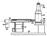
図13及び14を参照すると、製造ライン内への本発明のガラス容器を回転させるための装置の設置形態が示されている。ガラス容器290は、頂部プレート294の上方に配置されているデッドプレート292上に支持されており、ガラス容器290は、一対のローラー296によってその底部近くの一方の側面及び第二のローラーの対298によってその頂部近くの一方の側面を回転可能に支持されている。本発明のガラス容器を回転させるための装置の末端は、ローラー296及びローラー298の反対側の側面においてガラス容器290と接触状態とされている。周囲に容器回転ベルト250が備えられている容器回転ホイール192の末端部分は、ガラス容器290と接触して当該ガラス容器を回転させることがわかるであろう。
Referring to FIGS. 13 and 14, there is shown an installation configuration of the apparatus for rotating the glass container of the present invention in the production line. The
本発明のガラス容器を回転させる装置は、一端(図示せず)が固定的に取り付けられている支持部材300によって支持されている。支持部材300の他端は、スプリット構造を有し且つその内部に基部アセンブリの取り付けブラケット106の筒状部分108を収容している。本発明のガラス容器を回転させる装置は、筒状部分108の軸線を中心に回転せしめられると共に周囲に容器回転ベルト250が備えられた容器回転ホイール192の末端部分をガラス容器290のより近くへと又はより遠くへと動かすように長手方向に調整することができることが分かるであろう。支持部材300は、筒状部分108及び本発明のガラス容器を回転させる装置を、所望の位置に係止するために使用することができる係止ボルト302を備えている。
The apparatus for rotating a glass container of the present invention is supported by a
ローラー296及びローラー298だけでなく容器回転ベルト250が周囲に設置されている容器回転ホイール192も、回転せしめられるときに、デッドプレート292上にガラス容器を保持する機能を果たすことが当業者に理解されるであろう。ガラス容器の基部がデッドプレート292と接触したままであることを確保するためには、本発明のガラス容器を回転させるための装置を角度を付けて、容器回転ベルトがガラス容器290を回転させるときに容器回転ベルト250がガラス容器に下向きの力を付与することを確保することが望ましい。水平からせいぜい2°の角度(ガラス容器の面に対する容器回転ベルト250の動作方向下向きの角度)が適切であることが判明している。
Those skilled in the art understand that the
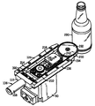
次に図15〜18を参照すると、本発明のガラス容器を回転させるための装置が、ガラス容器290を回転させる状態で示されている。図15及び16は、ガラス容器290を回転させるために容器回転ホイール192の周囲の容器回転ベルト250の経路を示すために、上方主プレート162及びカバー254が取り外された状態で示されており、特に、容器回転ベルト250に適正な張力を維持するためにベルトテンショナーアセンブリ(テンショナープレート228、テンショナーキャリア236及びアイドラプーリー242を備えている)を使用する方法を示している。これらの図はまた、駆動ベルトプーリー96及びアイドラプーリー210、212の各々の上の歯の中心に各々配置されている容器回転ホイール192及び環状のリブが、容器回転ベルト250をその支持装置上の定位置に保持するために、歯272の中間で容器回転ベルト250の中心線に配置されている溝274と相互作用する方法を実証している。
Referring now to FIGS. 15-18, an apparatus for rotating the glass container of the present invention is shown rotating the
図17及び18は、本発明のガラス容器を回転させるための装置が占める極めて限られた大きさのスペースを示しており、当該装置全体は、特に当該装置がガラス容器と接触して当該ガラス容器を回転させる位置で、容器回転ホイール192の直径よりも若干大きい直径及び容器回転ベルト250の厚みの幅を有している。本発明のガラス容器を回転させるための装置はまた、主に、容器回転ホイール192及び容器回転ベルト250を使用している装置の設計に因り極めて薄いので、跡形が極めて小さい。図18はまた、(テンショナープレート228、テンショナーキャリア236及びアイドラプーリー242を備えている)ベルトテンショナーアセンブリを調整するために支持プレート98内の開口部146を介するボルト246へのアクセス方法を示している。
FIGS. 17 and 18 show a very limited space occupied by the device for rotating the glass container of the present invention. The entire device is in particular in contact with the glass container. And a width of the thickness of the
最後に、図19〜20を参照すると、本発明のガラス容器を回転させるための装置が、ガラス容器290を回転させる作動状態で示されている。図19は検査ステーション位置へと回転されつつあるプロセスにおけるガラス容器290を示しており、図20は、検査ステーション位置へと移動されているが、最大回転速度まで加速されていない状態のガラス容器を示しており、図21は、検査ステーションにおいて最大回転速度状態にあるガラス容器290を示している。
Finally, referring to FIGS. 19-20, an apparatus for rotating a glass container of the present invention is shown in an actuated state of rotating a
図19においては、キャリッジアセンブリは、バネワッシャ180が筒状通路284の端部に達してキャリッジアセンブリの移動を止めている位置へと圧縮バネ174によって前方へ付勢されていることを見ることができる。この位置においては、容器回転ベルト250及び容器回転ホイール192が、ガラス容器が検査ステーション内にあるときにガラス容器が位置する場所の内側に配置されることに注目することができる。
In FIG. 19, it can be seen that the carriage assembly is biased forward by the
図20においては、ガラス容器290は、検査ステーション内の位置にあるが、主としてガラス容器20の慣性により未だ最大回転速度まで回転していない。キャリッジアセンブリは、ガラス容器290によってかけられる力により、容器回転ベルト250及び容器回転ホイール192に対して幾分後退せしめられた状態にあることを見ることができる。圧縮バネ174は、容器回転ホイール192及びその周囲の容器回転ベルトの一部分を含んでいるキャリッジアセンブリをガラス容器290と接触する状態へと付勢する。
In FIG. 20, the
移動しつつある容器回転ベルト250がガラス容器290を回転させ始める(しかしながら、ガラス容器290は最大速度では回転していない)と、容器回転ホイール192からアイドラプーリー210及び214の周囲を通り駆動ベルトプーリー96まで伸長している容器回転ベルト250の一部分は、より高負荷となって容器回転ベルト250のこの部分の張力を増大させる。容器回転ベルト250のこの増大された張力によって、この駆動ベルト経路の一部分のみが動かすのではなく引っ張られ、アイドラプーリー214(キャリッジアセンブリのモーターアセンブリ190上に取り付けられている)と駆動ベルトプーリー96との間の部分は、キャリッジアセンブリを末端方向へと引っ張って、容器回転ベルト250及び容器回転ホイール192がより大きな力でガラス容器内へと駆動せしめられる。
When the moving
ガラス容器290がその最終回転速度に近づくと、容器回転ベルト250の張力が低下し、圧縮バネ174を、キャリッジアセンブリを容器へと駆動するように作用している力としてのみ残す。容器回転ベルト250の幾何学的構造のこの自動補力作用は、ガラス容器を回転させる装置が、より小さな時間加重平均接触力がガラス容器に対してかけられる状態で作動するのを可能にする(これは、もちろん、本発明のガラス容器を回転させるための装置の構成要素の寿命を長くするであろう)。
As the
従って、本発明のガラス容器を回転させるための装置が極めてコンパクトであり、回転されつつあるガラス容器の近くの領域に最小の体積を使用するのを可能にし、それによって、検査ステーションのための最大の空間を可能にすることが本発明の例示的な実施形態の上記の詳細な説明からわかる。本発明のガラス容器を回転させる装置は、コンパクトな大きさにかかわらず、各ガラス容器を検査するのに必要とされる時間を最短にするために急速に加速するためにガラス容器に十分なトルクを供給する機能を有している。本発明のガラス容器を回転させるための装置は、極めて適合性のある駆動面を提供し且つガラス容器の外壁を迅速に“捕らえて”、その慣性に迅速に打ち勝ち且つそれを加速して回転させる高い機能をも提供する。 Thus, the apparatus for rotating the glass container of the present invention is extremely compact, allowing the use of a minimum volume in the area near the glass container being rotated, thereby providing a maximum for an inspection station. It can be seen from the above detailed description of the exemplary embodiments of the present invention. The device for rotating glass containers of the present invention, regardless of its compact size, has sufficient torque on the glass containers to accelerate rapidly to minimize the time required to inspect each glass container. It has the function to supply. The apparatus for rotating the glass container of the present invention provides a very compatible drive surface and quickly "captures" the outer wall of the glass container to quickly overcome its inertia and accelerate it to rotate. It also provides high functionality.
本発明のガラス容器を回転させるための装置は、ガラス容器に低レベルの衝撃を付与し且つガラス容器を損傷させることなく又はガラス容器によって損傷を受けることなく、迅速に当該ガラス容器と接触する状態へと移動する顕著な機能を備えている。本発明のガラス容器を回転させるための装置はまた、ガラス容器に下向きに作用する力を付与して、ガラス容器が高速度で回転されつつあるときに当該ガラス容器を下方へ後退させるように機能することができる。本発明のガラス容器を回転させるための装置は、丈夫な機械的設計及び高い信頼性を有して、これらが備わっていないことによって惹き起こされる製造ロスを避けることができる。 The apparatus for rotating the glass container of the present invention is a state in which the glass container is brought into contact with the glass container quickly without giving a low level impact and without damaging or being damaged by the glass container. It has a remarkable function to move to. The apparatus for rotating the glass container of the present invention also functions to apply a downward force to the glass container so that the glass container is retracted downward when the glass container is being rotated at a high speed. can do. The apparatus for rotating the glass container of the present invention has a robust mechanical design and high reliability, and can avoid manufacturing loss caused by the absence of these.
本発明のガラス容器を回転させる装置は、耐久性があると共に長持ちする構造であり且つ迅速な修理を可能にし且つその作動寿命全体に亘ってユーザーによるメンテナンスの提供の必要性が比較的まれである構造特性を有している。本発明のガラス容器を回転させるための装置はまた、その市場の受けを高め且つそれによって最も広い可能な市場を付与するための低廉な構造である。最後に、本発明のガラス容器を回転させるための装置及び方法の上記の利点及び目的の全てが、実質的に相対的な欠点を生じさせることなく達成される。 The apparatus for rotating glass containers of the present invention is durable and long-lasting and allows for quick repairs and the need to provide maintenance by the user over its entire operating life is relatively rare. Has structural characteristics. The apparatus for rotating the glass container of the present invention is also an inexpensive structure to increase its market acceptance and thereby give the widest possible market. Finally, all of the above advantages and objectives of the apparatus and method for rotating the glass container of the present invention are achieved without causing substantial relative disadvantages.
本発明のガラス容器を回転させるための装置及び方法の上記の説明は、特定の実施形態及び用途に関連して示され且つ説明されているけれども、これは、図示及び説明の目的で提供されたものであり、包括的であること又は本発明をここに開示された特別な実施形態及び用途に限定することを意図していない。本発明の精神又は範囲を逸脱することなく、ここに記載された発明に対して多くの変更、改造、変形又は代替を施しても良いことは当業者に明らかとなるであろう。以上、想到される特定の使用方法に適するように且つ当業者が種々の実施形態で及び種々の変形例によって本発明を使用することができるように本発明の原理及びその特別な用途の最良の例示を提供するために、特別な実施形態及び用途を選択し且つ説明した。従って、このような変更、変形、変形及び代替例は、添付の各請求項が公正に、法的に、公平に付与される範囲に従って解釈されるときに、これらの請求項によって決定される本発明の範囲内に含まれると考えられるべきである。 Although the above description of the apparatus and method for rotating a glass container of the present invention has been shown and described in connection with specific embodiments and applications, this was provided for purposes of illustration and description. It is intended to be exhaustive and not intended to be exhaustive or to limit the invention to the specific embodiments and uses disclosed herein. It will be apparent to those skilled in the art that many changes, modifications, variations and alternatives can be made to the invention described herein without departing from the spirit or scope of the invention. The best of the principles of the present invention and its special application so that it can be used in a variety of embodiments and with various modifications so as to be suitable for the particular method of use envisaged Special embodiments and applications have been selected and described to provide examples. Accordingly, such changes, modifications, variations and alternatives may be determined by the claims as they are construed when accorded the scope of the appended claims fairly, legally and fairly. It should be considered as included within the scope of the invention.
Claims (16)
前記検査ステーションは、当該ガラス容器を回転させるための装置が係合せしめられるべき当該ガラス容器の側面と反対側の側面によって前記検査ステーション内のガラス容器を回転させることができるように支持するためのローラーを備えており、
当該ガラス容器を回転させるための装置は、
前記ローラーによって支持されるガラス容器の側面と反対側の側面上に、前記検査ステーションに対して調整可能な固定位置に設置するための基部部材と、
前記検査ステーション内のガラス容器に接近し或いはガラス容器から離れるように直線状の可動形態で前記基部部材上に取り付けられたキャリッジ部材であって、互いに反対の基端と末端とを有し、前記末端は前記検査ステーションに最も近い位置にあり、前記基端は前記検査ステーションから最も遠い位置にある、前記キャリッジ部材と、
前記キャリッジ部材の末端において当該キャリッジ部材に回転可能に取り付けられている容器回転ホイールであって、当該容器回転ホイールの一部分が前記キャリッジ部材の前記末端から外方へ伸長するようになされている前記容器回転ホイールと、
モーターであって、当該モーターによって駆動される駆動ベルトプーリーを備えているモーターと、
前記駆動ベルトプーリー及び前記容器回転ホイール上に取り付けられた容器回転ベルトであって、それによって、前記モーターが、前記容器回転ベルトと前記容器回転ホイールとの両方を駆動するようになされた前記容器回転ベルトと、を備えており、
前記容器回転ベルトの一部分は、前記キャリッジ部材の前記末端に近接した位置で外方に向かって伸長している前記容器回転ホイールの一部分上に配置されており、前記容器回転ベルトは、前記ガラス容器を回転させるために、前記ローラーによって支持されている前記ガラス容器の側面と反対側の当該ガラス容器の側面と接触しており、
前記キャリッジ部材の前記容器回転ベルトが取り付けられている前記基端において前記キャリッジ部材に取り付けられている少なくとも1つのアイドラプーリーであって、前記駆動ベルトプーリーが、当該少なくとも1つのアイドラプーリーよりも前記キャリッジ部材の前記末端に対してより近くに配置されている、前記少なくとも1つのアイドラプーリーを更に備えており、
検査ステーション内のガラス容器が、前記容器回転ベルトによって未だ最大回転速度まで回転されていないときにはいつでも、前記モーターは、前記容器回転ホイールから前記少なくとも1つのアイドラプーリーの周囲を通って前記駆動ベルトプーリーまで伸長している前記容器回転ベルトの部分の張力を増すように前記駆動ベルトプーリーを作動させ、それによって、前記キャリッジ部材を検査ステーション内のガラス容器へと近づく方向に付勢するようになされていることを特徴とする、ガラス容器を回転させるための装置。 An apparatus for rotating a glass container to be inspected, which is continuously indexed into and out of an inspection station supporting a vertical configuration on a surface;
The inspection station supports a glass container in the inspection station to be rotated by a side opposite to the side of the glass container to be engaged with a device for rotating the glass container. Equipped with rollers,
An apparatus for rotating the glass container is:
A base member for installation at a fixed position adjustable with respect to the inspection station on a side opposite to the side of the glass container supported by the roller;
A carriage member mounted on the base member in a linear movable form so as to approach or separate from the glass container in the inspection station, the carriage member having a base end and a distal end opposite to each other, The carriage member at a distal end closest to the inspection station and the proximal end furthest from the inspection station;
A container rotating wheel rotatably attached to the carriage member at an end of the carriage member, wherein the container is configured such that a part of the container rotating wheel extends outward from the end of the carriage member. A rotating wheel,
A motor comprising a drive belt pulley driven by the motor;
The container rotation belt mounted on the drive belt pulley and the container rotation wheel, whereby the motor rotates the motor to drive both the container rotation belt and the container rotation wheel. A belt, and
A portion of the container rotation belt is disposed on a portion of the container rotation wheel that extends outwardly at a position proximate to the end of the carriage member, the container rotation belt comprising the glass container In contact with the side surface of the glass container opposite to the side surface of the glass container supported by the roller,
And at least one idler pulley mounted on Oite the carriage member to the proximal end the ware rotate belt of the carriage member is mounted, said drive belt pulley, from the at least one idler pulley Further comprising the at least one idler pulley disposed closer to the end of the carriage member;
Whenever the glass container in the inspection station has not yet been rotated to maximum rotational speed by the container rotating belt, the motor passes from the container rotating wheel through the periphery of the at least one idler pulley to the drive belt pulley. The drive belt pulley is actuated to increase the tension of the portion of the container rotating belt that extends, thereby urging the carriage member toward the glass container in the inspection station. wherein the apparatus for rotating glass containers.
前記基部部材が、前記キャリッジ部材による前記検査ステーションに近づいたり当該検査ステーションから離れたりする直線的な動きを許容する共に、当該キャリッジ部材の前記検査ステーションに近づいたり遠ざかったりする直線的な動きの軸線に対して平行な軸線を中心とする前記キャリッジ部材の回転動作を許容する形態で支持部材に固定されている取り付けブラケットを備えていることを特徴とする装置。 The apparatus of claim 1,
An axis of linear movement of the base member allowing the carriage member to move linearly toward and away from the inspection station and moving the carriage member toward and away from the inspection station. And a mounting bracket fixed to the support member in a manner that allows the carriage member to rotate about an axis parallel to the support member.
前記キャリッジ部材の回転動作が、前記容器回転ホイールと当該容器回転ホイールの一部分上に配置されている容器回転ベルトの前記キャリッジ部材の末端で外方へ向かって伸長している部分とが、水平面から2度未満の角度を付けられた面内にあって、前記ガラス容器が回転せしめられると、前記容器回転ベルトの動きによって、前記検査ステーション内のガラス容器に下向きの力が付与されるように調整されることを特徴とする装置。 The apparatus according to claim 2,
The rotation of the carriage member is such that the container rotation wheel and a portion of the container rotation belt arranged on a part of the container rotation wheel that extends outward at the end of the carriage member from the horizontal plane. Adjusted so that a downward force is applied to the glass container in the inspection station by the movement of the container rotating belt when the glass container is rotated within an angled plane of less than 2 degrees. The apparatus characterized by being made.
前記基部部材が、前記キャリッジ部材を、前記直線状の形態で動くように支持するガイドであって、前記キャリッジ部材の各々の側面上に配置されている前記ガイドを備えており、当該ガイドは、動作中に、当該装置が受ける衝撃力を少なくするために、ポリマー材料によって作られていることを特徴とする装置。 The apparatus of claim 1,
The base member is a guide that supports the carriage member so as to move in the linear form, and includes the guide disposed on each side surface of the carriage member. A device characterized in that it is made of a polymer material in order to reduce the impact force it receives during operation.
前記検査ステーションにおいて、前記キャリッジ部材の末端をガラス容器に向かって付勢するために、前記キャリッジ部材に力をかける付勢装置を更に備えていることを特徴とする装置。 The apparatus of claim 1,
The inspection station further comprises a biasing device that applies a force to the carriage member to bias the end of the carriage member toward the glass container.
前記付勢装置が、
前記検査ステーションから最も遠い端部で前記基部部材に取り付けられている取り付けブラケットと、
前記キャリッジ部材の前記基端に取り付けられた後方スペーサブロックと、
前記取り付けブラケットと前記後方スペーサブロックとの間に配置されている少なくとも1つのバネと、を備えていることを特徴とする装置。 An apparatus according to claim 5,
The biasing device comprises:
A mounting bracket attached to the base member at the end furthest from the inspection station;
A rear spacer block attached to the proximal end of the carriage member;
At least one spring disposed between the mounting bracket and the rear spacer block.
前記検査ステーション内のガラス容器に向かって前記キャリッジ部材の末端を付勢するために該キャリッジ部材にかけられる力を変えるために、前記基部部材上の前記取り付けブラケットの位置が、前記検査ステーションに対して近づいたり遠ざかったりするように直線的に移動可能であることを特徴とする装置。 The device according to claim 6,
In order to change the force applied to the carriage member to urge the end of the carriage member toward the glass container in the inspection station, the position of the mounting bracket on the base member is relative to the inspection station. A device that is linearly movable so as to approach or move away.
前記容器回転ホイールが、ポリウレタンのような弾性材料によって作られていることを特徴とする装置。 The apparatus of claim 1,
A device characterized in that the container rotating wheel is made of an elastic material such as polyurethane.
前記容器回転ホイール及び前記駆動ベルトプーリーが、前記容器回転ベルトの内面上に設けられている歯とかみ合うように歯が切られていることを特徴とする装置。 The apparatus of claim 1,
An apparatus wherein the container rotating wheel and the drive belt pulley are toothed so as to mesh with teeth provided on the inner surface of the container rotating belt.
前記容器回転ホイール及び前記駆動ベルトプーリーの各々が、各々の中心線において前記歯の外方へ伸長している環状のリブを備えており、
長手方向に伸長している溝が、前記容器回転ベルトの中心線位置において、当該容器回転ベルトの前記内側側面上の前記歯内に切り込まれていることを特徴とする装置。 An apparatus according to claim 9,
Each of the container rotating wheel and the drive belt pulley comprises an annular rib extending outwardly of the tooth at a respective centerline;
A longitudinally extending groove is cut into the teeth on the inner side of the container rotating belt at a centerline position of the container rotating belt.
前記容器回転ベルトの前記歯がネオプレンによって作られており、前記容器回転ベルトの内部に補強繊維が含まれていることを特徴とする装置。 An apparatus according to claim 9,
An apparatus according to claim 1, wherein the teeth of the container rotating belt are made of neoprene, and reinforcing fibers are contained inside the container rotating belt.
前記容器回転ベルトが、ネオプレン、白ラバー、傷が付かないラバーのような弾性の摩擦性材料によって作られている外面を備えていることを特徴とする装置。 The apparatus of claim 1,
The apparatus characterized in that the container rotating belt has an outer surface made of an elastic friction material such as neoprene, white rubber, non-scratch rubber.
前記モーター及び前記駆動ベルトプーリーが、本体アセンブリ上に取り付けられており且つ前記キャリッジ部材が直線的形態で前記検査ステーション内のガラス容器に近づいたり遠ざかったりするように動くときに移動しないことを特徴とする装置。 The apparatus of claim 1,
The motor and the drive belt pulley are mounted on a body assembly and do not move when the carriage member moves in a linear form to move toward or away from a glass container in the inspection station. Device to do.
前記容器回転ベルトの張力を調整するように調整可能であるアイドラプーリーを備えているテンショナーアセンブリを更に備えていることを特徴とする装置。 The apparatus of claim 1,
The apparatus further comprises a tensioner assembly comprising an idler pulley that is adjustable to adjust the tension of the container rotating belt.
前記駆動ベルトプーリー、前記容器回転ベルト及び前記容器回転ホイールが、全て、同じ水平面内に配置されていることを特徴とする装置。 The apparatus of claim 1,
The drive belt pulley, the container rotating belt, and the container rotating wheel are all arranged in the same horizontal plane.
当該ガラス容器を回転させる方法は、
前記検査ステーション内にあるガラス容器の前記ローラーによって支持されるガラス容器の側面と反対側の側面上の前記検査ステーションに対して調整可能に固定される位置に基部部材を設置するステップと、
前記検査ステーション内のガラス容器に対して近づいたり遠ざかったりする直線的に可動の形態で前記基部部材上にキャリッジ部材を取り付けるステップであって、前記キャリッジ部材は、互いに反対の基端と末端とを有し、前記末端は前記検査ステーションに最も近い位置にあり、前記基端は前記検査ステーションから最も遠い位置にある、前記キャリッジ部材を取り付けるステップと、
容器回転ホイールの一部分が前記キャリッジ部材の末端から外方へ伸長するように、前記キャリッジ部材の末端に前記容器回転ホイールを回転可能に取り付けるステップと、
駆動ベルトプーリーをモーターによって駆動するステップと、
前記駆動ベルトプーリー及び前記容器回転ホイール上に容器回転ベルトを取り付けるステップであり、それによって、前記モーターが、前記容器回転ベルトと前記容器回転ホイールとの両方を駆動するようにするステップと、
前記容器回転ベルトが取り付けられている前記基端において前記キャリッジ部材上に取り付けられている少なくとも1つのアイドラプーリーであって、前記駆動ベルトプーリーが、当該少なくとも1つのアイドラプーリーよりも前記キャリッジ部材の前記末端に対してより近くに配置されている、前記少なくとも1つのアイドラプーリーを設けるステップと、を含み、
前記容器回転ベルトの一部分が、前記キャリッジ部材の前記末端から外方へ伸長している前記容器回転ホイールの一部分に配置され、前記容器回転ベルトは、前記ローラーによって支持されている前記ガラス容器の側面と反対側の前記検査ステーション内のガラス容器の側面と接触して、前記ガラス容器を回転させるようにし、
前記容器回転ホイール、前記駆動ベルトプーリー、並びに前記少なくとも1つのアイドラプーリー及び前記容器回転ベルトの経路は、各々、検査ステーション内のガラス容器が未だ前記容器回転ベルトによって最大回転速度まで回転されていないときにはいつでも、前記モーターが前記駆動ベルトプーリーを作動させて、前記容器回転ホイールから前記少なくとも1つのアイドラプーリーの周囲を通って駆動ベルトプーリーまで延びている前記容器回転ベルトの部分の張力を増大させ、それによって、前記キャリッジ部材を、前記検査ステーション内のガラス容器に向かって末端方向へ付勢するようにさせる、ことを特徴とする方法。 A method for rotating glass containers continuously indexed to and from an inspection station that supports a glass container to be inspected in a vertical configuration on a surface, the inspection station comprising: A roller for rotatably supporting the glass container with respect to the side opposite to the side of the glass container with which the device for rotating is engaged;
The method of rotating the glass container is as follows:
Installing a base member in a position that is adjustably fixed relative to the inspection station on the side opposite to the side of the glass container supported by the roller of the glass container in the inspection station;
Mounting a carriage member on the base member in a linearly movable manner approaching or moving away from a glass container in the inspection station, the carriage member having a base end and a distal end opposite to each other; Attaching the carriage member, wherein the distal end is closest to the inspection station and the proximal end is furthest from the inspection station;
Rotatably mounting the container rotation wheel at the end of the carriage member such that a portion of the container rotation wheel extends outwardly from the end of the carriage member;
Driving the drive belt pulley by a motor;
Mounting a container rotating belt on the drive belt pulley and the container rotating wheel, thereby causing the motor to drive both the container rotating belt and the container rotating wheel;
And at least one idler pulley mounted on Oite the carriage member on the proximal end said ware rotate belt is mounted, said drive belt pulley, said carriage member than the at least one idler pulley Providing said at least one idler pulley disposed closer to said end of
A portion of the container rotation belt is disposed on a portion of the container rotation wheel that extends outwardly from the end of the carriage member, the container rotation belt being supported by the rollers on the side of the glass container. In contact with the side of the glass container in the inspection station on the opposite side to rotate the glass container,
The container rotation wheel, the drive belt pulley, and the path of the at least one idler pulley and the container rotation belt are each when the glass container in the inspection station is not yet rotated to the maximum rotation speed by the container rotation belt. At any time, the motor actuates the drive belt pulley to increase the tension of the portion of the container rotation belt that extends from the container rotation wheel through the circumference of the at least one idler pulley to the drive belt pulley ; And urging the carriage member distally toward the glass container in the inspection station.
Applications Claiming Priority (2)
| Application Number | Priority Date | Filing Date | Title |
|---|---|---|---|
| US12/253,951 | 2008-10-18 | ||
| US12/253,951 US8429989B2 (en) | 2008-10-18 | 2008-10-18 | Modular apparatus and method for rotating glass containers and the like |
Publications (3)
| Publication Number | Publication Date |
|---|---|
| JP2010095386A JP2010095386A (en) | 2010-04-30 |
| JP2010095386A5 JP2010095386A5 (en) | 2012-05-17 |
| JP5500878B2 true JP5500878B2 (en) | 2014-05-21 |
Family
ID=41572326
Family Applications (1)
| Application Number | Title | Priority Date | Filing Date |
|---|---|---|---|
| JP2009145977A Expired - Fee Related JP5500878B2 (en) | 2008-10-18 | 2009-06-19 | Modular apparatus and method for rotating glass containers and the like |
Country Status (4)
| Country | Link |
|---|---|
| US (1) | US8429989B2 (en) |
| EP (1) | EP2177899B1 (en) |
| JP (1) | JP5500878B2 (en) |
| RU (1) | RU2507504C2 (en) |
Families Citing this family (8)
| Publication number | Priority date | Publication date | Assignee | Title |
|---|---|---|---|---|
| DE102011056609A1 (en) * | 2011-12-19 | 2013-06-20 | Schuler Pressen Gmbh | Device for transporting cylindrical containers |
| US8973733B2 (en) * | 2012-01-04 | 2015-03-10 | Douglas Machine Inc. | Article orienter and attendant orientation operations |
| CN103308527B (en) * | 2013-05-30 | 2015-02-11 | 屈桢深 | Detection method and detection system for foreign matters in infusion bottle |
| US9527163B2 (en) * | 2014-10-29 | 2016-12-27 | Provide Commerce, Inc. | Support apparatus |
| WO2016171197A1 (en) * | 2015-04-24 | 2016-10-27 | ニプロ株式会社 | Method for producing medical glass container, and fire blast device provided with rotator |
| EP3797883B1 (en) | 2019-09-27 | 2022-06-08 | SCHOTT Schweiz AG | Apparatus for inspecting a pharmaceutical container |
| EP3798621B1 (en) | 2019-09-27 | 2022-11-23 | SCHOTT Schweiz AG | Apparatus for inspecting a pharmaceutical container |
| EP3855174B1 (en) | 2020-01-23 | 2024-05-15 | SCHOTT Pharma Schweiz AG | Detection and characterization of defects in pharmaceutical cylindrical containers |
Family Cites Families (37)
| Publication number | Priority date | Publication date | Assignee | Title |
|---|---|---|---|---|
| US3262561A (en) | 1964-06-15 | 1966-07-26 | Owens Illinois Inc | Inspecting and assorting glass containers |
| US3348049A (en) | 1964-12-31 | 1967-10-17 | Ball Brothers Res Corp | High speed ultraviolet thin spot detector |
| GB1155976A (en) | 1966-06-30 | 1969-06-25 | Arthur Terence Ranson | Glassware Inspection Apparatus. |
| US3410388A (en) * | 1967-02-03 | 1968-11-12 | Robert D. Hendrickson | Bottle handling apparatus |
| US3460669A (en) | 1967-07-31 | 1969-08-12 | Owens Illinois Inc | Container indexing and rotating |
| US3426884A (en) | 1967-08-15 | 1969-02-11 | Solar Eng & Equipment Co | Glass bottle handling apparatus |
| US3557950A (en) | 1968-09-24 | 1971-01-26 | Powers Manufacturing | Photo-electric crack detector for glass bottles |
| US3684089A (en) | 1970-09-21 | 1972-08-15 | Brockway Glass Co Inc | Container wall thickness detection |
| US3735855A (en) | 1970-12-28 | 1973-05-29 | Owens Illinois Inc | Container rotating apparatus |
| US3690456A (en) | 1971-06-25 | 1972-09-12 | Powers Manufacturing | Glass container crack detector |
| CH548599A (en) | 1972-01-19 | 1974-04-30 | Emhart Zuerich Sa | Crack testing station for the sorting line of a plant for the production of glass containers. |
| US4021122A (en) | 1973-01-02 | 1977-05-03 | Emhart Zurich S.A. | Glass container inspection machine |
| JPS5228432B2 (en) * | 1973-10-29 | 1977-07-26 | ||
| US3957154A (en) | 1974-01-29 | 1976-05-18 | Hitachi Shipbuilding And Engineering Co., Ltd. | Apparatus for rotating bottles |
| CH570912A5 (en) | 1974-03-11 | 1975-12-31 | Emhart Zuerich Sa | |
| US3991883A (en) | 1974-05-06 | 1976-11-16 | Powers Manufacturing Incorporated | Method and apparatus for identifying a bottle |
| US4323158A (en) | 1980-07-03 | 1982-04-06 | Wheaton Industries | Bottle neck finish inspection apparatus |
| JPS603542A (en) | 1983-06-21 | 1985-01-09 | Mitsubishi Electric Corp | Bottle inspecting device |
| US4653628A (en) | 1984-03-23 | 1987-03-31 | Emhart Industries, Inc. | Apparatus for orienting containers |
| US5028769A (en) | 1986-08-20 | 1991-07-02 | Emhart Industries, Inc. | Device for reading a mold code on a glass bottle |
| US4915237A (en) | 1986-09-11 | 1990-04-10 | Inex/Vistech Technologies, Inc. | Comprehensive container inspection system |
| US4786801A (en) | 1987-07-21 | 1988-11-22 | Emhart Industries Inc. | Finish Leak Detector having vertically movable light source |
| US4967070A (en) | 1989-07-19 | 1990-10-30 | Owens-Brockway Glass Container Inc. | Indentification of a molded container with its mold of origin |
| GB9309238D0 (en) * | 1993-05-05 | 1993-06-16 | British Nuclear Fuels Plc | Apparatus for detection of surface defects |
| US5405015A (en) | 1993-08-11 | 1995-04-11 | Videojet Systems International, Inc. | System and method for seeking and presenting an area for reading with a vision system |
| EP0642995A1 (en) * | 1993-09-15 | 1995-03-15 | Emhart Glass Machinery Investments Inc. | Tapered container handler |
| JP3351910B2 (en) | 1994-09-01 | 2002-12-03 | エーザイ株式会社 | Vial bottle inspection method and equipment |
| DE29518639U1 (en) * | 1995-11-24 | 1997-03-27 | Heuft Systemtechnik Gmbh | Device for transporting containers past a device for inspecting the bottom of the containers |
| US5608516A (en) | 1995-12-13 | 1997-03-04 | Emhart Glass Machinery Investments Inc. | Glass bottle inspection machine |
| DE19605133C2 (en) | 1996-02-13 | 2000-06-15 | Krones Ag | Inspection machine for vessels |
| US5823317A (en) | 1996-12-04 | 1998-10-20 | New England Machinery, Inc. | Apparatus for uniformly orientating articles |
| US6067155A (en) * | 1997-12-24 | 2000-05-23 | Owens-Brockway Glass Container Inc. | Optical inspection of transparent containers using infrared and polarized visible light |
| US5895911A (en) | 1998-01-22 | 1999-04-20 | Emhart Glass S.A. | Glass container body check detector |
| US6198102B1 (en) * | 1998-06-17 | 2001-03-06 | Owens-Brockway Glass Container Inc. | Inspection of container mouth using infrared energy emitted by the container bottom |
| US6172355B1 (en) * | 1998-10-13 | 2001-01-09 | Owens-Brockway Glass Container Inc. | In-line inspection of containers |
| JP3062611U (en) * | 1999-03-31 | 1999-10-08 | 三ツ星ベルト株式会社 | Toothed belt |
| US7010863B1 (en) * | 2004-01-26 | 2006-03-14 | Owens-Brockway Glass Container Inc. | Optical inspection apparatus and method for inspecting container lean |
-
2008
- 2008-10-18 US US12/253,951 patent/US8429989B2/en active Active
-
2009
- 2009-06-19 JP JP2009145977A patent/JP5500878B2/en not_active Expired - Fee Related
- 2009-10-13 EP EP09172944.2A patent/EP2177899B1/en active Active
- 2009-10-16 RU RU2009138355/03A patent/RU2507504C2/en active
Also Published As
| Publication number | Publication date |
|---|---|
| US8429989B2 (en) | 2013-04-30 |
| RU2507504C2 (en) | 2014-02-20 |
| EP2177899A1 (en) | 2010-04-21 |
| US20100095790A1 (en) | 2010-04-22 |
| EP2177899B1 (en) | 2015-01-21 |
| JP2010095386A (en) | 2010-04-30 |
| RU2009138355A (en) | 2011-04-27 |
Similar Documents
| Publication | Publication Date | Title |
|---|---|---|
| JP5500878B2 (en) | Modular apparatus and method for rotating glass containers and the like | |
| US8328603B2 (en) | Apparatus for stress shot peening of coil spring | |
| KR101622884B1 (en) | automatic bending device for metal working | |
| EP0994344B9 (en) | In-line inspection of containers | |
| CA1210245A (en) | Take-out arm for bottle forming machine | |
| JP7382475B2 (en) | Container inspection equipment | |
| CN100560737C (en) | A kind of blast furnace bellless furnace top distributor | |
| GB1589032A (en) | Apparatus for testing frangible containers | |
| US6390282B1 (en) | Horizontal belt conveyor with quick vertical adjustment | |
| CN101318598B (en) | Clamping apparatus for cloth roller | |
| GB2427180A (en) | In line package tipper | |
| CN113060499A (en) | But height-adjusting's goods conveyor | |
| US5608516A (en) | Glass bottle inspection machine | |
| KR20030050910A (en) | Apparatus for assembling and disassembling automatically a bearing | |
| CN213749656U (en) | Bottle lamp inspection machine | |
| JP2006321589A (en) | Sorting device | |
| CN219656535U (en) | Air knife dryer | |
| CN108438739B (en) | Servo rubber chain conveying system for ceramic panel | |
| CN219578174U (en) | Fine dried noodle shaping mechanism | |
| CN220862066U (en) | Device for screening rubber rings with different thicknesses | |
| CN220104889U (en) | Injection molding gap detection equipment | |
| CN115818129B (en) | Automatic steel conveyor for building construction | |
| CN220392269U (en) | Conveyer belt baffle protection device | |
| JP3143437U (en) | Resin container label peeling device | |
| CN219390828U (en) | Automatic glass detection device |
Legal Events
| Date | Code | Title | Description |
|---|---|---|---|
| A521 | Request for written amendment filed |
Free format text: JAPANESE INTERMEDIATE CODE: A523 Effective date: 20120327 |
|
| A621 | Written request for application examination |
Free format text: JAPANESE INTERMEDIATE CODE: A621 Effective date: 20120327 |
|
| A977 | Report on retrieval |
Free format text: JAPANESE INTERMEDIATE CODE: A971007 Effective date: 20130926 |
|
| A131 | Notification of reasons for refusal |
Free format text: JAPANESE INTERMEDIATE CODE: A131 Effective date: 20130930 |
|
| A521 | Request for written amendment filed |
Free format text: JAPANESE INTERMEDIATE CODE: A523 Effective date: 20131029 |
|
| A131 | Notification of reasons for refusal |
Free format text: JAPANESE INTERMEDIATE CODE: A131 Effective date: 20131120 |
|
| A521 | Request for written amendment filed |
Free format text: JAPANESE INTERMEDIATE CODE: A523 Effective date: 20140109 |
|
| TRDD | Decision of grant or rejection written | ||
| A01 | Written decision to grant a patent or to grant a registration (utility model) |
Free format text: JAPANESE INTERMEDIATE CODE: A01 Effective date: 20140210 |
|
| A61 | First payment of annual fees (during grant procedure) |
Free format text: JAPANESE INTERMEDIATE CODE: A61 Effective date: 20140311 |
|
| R150 | Certificate of patent or registration of utility model |
Ref document number: 5500878 Country of ref document: JP Free format text: JAPANESE INTERMEDIATE CODE: R150 |
|
| R250 | Receipt of annual fees |
Free format text: JAPANESE INTERMEDIATE CODE: R250 |
|
| R250 | Receipt of annual fees |
Free format text: JAPANESE INTERMEDIATE CODE: R250 |
|
| R250 | Receipt of annual fees |
Free format text: JAPANESE INTERMEDIATE CODE: R250 |
|
| R250 | Receipt of annual fees |
Free format text: JAPANESE INTERMEDIATE CODE: R250 |
|
| R250 | Receipt of annual fees |
Free format text: JAPANESE INTERMEDIATE CODE: R250 |
|
| LAPS | Cancellation because of no payment of annual fees |