RU2419731C2 - Centrifugal compressor - Google Patents
Centrifugal compressor Download PDFInfo
- Publication number
- RU2419731C2 RU2419731C2 RU2008150660/06A RU2008150660A RU2419731C2 RU 2419731 C2 RU2419731 C2 RU 2419731C2 RU 2008150660/06 A RU2008150660/06 A RU 2008150660/06A RU 2008150660 A RU2008150660 A RU 2008150660A RU 2419731 C2 RU2419731 C2 RU 2419731C2
- Authority
- RU
- Russia
- Prior art keywords
- section
- fluid
- centrifugal compressor
- flow rate
- diffuser
- Prior art date
Links
- 239000012530 fluid Substances 0.000 claims abstract description 109
- 230000006835 compression Effects 0.000 claims description 21
- 238000007906 compression Methods 0.000 claims description 21
- 230000033001 locomotion Effects 0.000 claims description 12
- 238000000926 separation method Methods 0.000 claims description 7
- 230000007423 decrease Effects 0.000 claims description 6
- 230000015572 biosynthetic process Effects 0.000 claims description 3
- 230000001105 regulatory effect Effects 0.000 abstract description 4
- 230000003247 decreasing effect Effects 0.000 abstract description 2
- 230000000694 effects Effects 0.000 abstract 1
- 239000000126 substance Substances 0.000 abstract 1
- 230000000903 blocking effect Effects 0.000 description 8
- 238000010276 construction Methods 0.000 description 3
- 230000003068 static effect Effects 0.000 description 3
- 230000006866 deterioration Effects 0.000 description 2
- 239000012634 fragment Substances 0.000 description 2
- 230000004048 modification Effects 0.000 description 2
- 238000012986 modification Methods 0.000 description 2
- 230000002093 peripheral effect Effects 0.000 description 2
- 125000006850 spacer group Chemical group 0.000 description 2
- 238000011144 upstream manufacturing Methods 0.000 description 2
- 230000033228 biological regulation Effects 0.000 description 1
- 230000015556 catabolic process Effects 0.000 description 1
- 238000002485 combustion reaction Methods 0.000 description 1
- 238000006731 degradation reaction Methods 0.000 description 1
- 238000000034 method Methods 0.000 description 1
- 238000005192 partition Methods 0.000 description 1
- 238000011084 recovery Methods 0.000 description 1
- 210000001991 scapula Anatomy 0.000 description 1
Images


Classifications
-
- F—MECHANICAL ENGINEERING; LIGHTING; HEATING; WEAPONS; BLASTING
- F04—POSITIVE - DISPLACEMENT MACHINES FOR LIQUIDS; PUMPS FOR LIQUIDS OR ELASTIC FLUIDS
- F04D—NON-POSITIVE-DISPLACEMENT PUMPS
- F04D29/00—Details, component parts, or accessories
- F04D29/40—Casings; Connections of working fluid
- F04D29/42—Casings; Connections of working fluid for radial or helico-centrifugal pumps
- F04D29/44—Fluid-guiding means, e.g. diffusers
- F04D29/46—Fluid-guiding means, e.g. diffusers adjustable
- F04D29/462—Fluid-guiding means, e.g. diffusers adjustable especially adapted for elastic fluid pumps
-
- F—MECHANICAL ENGINEERING; LIGHTING; HEATING; WEAPONS; BLASTING
- F04—POSITIVE - DISPLACEMENT MACHINES FOR LIQUIDS; PUMPS FOR LIQUIDS OR ELASTIC FLUIDS
- F04D—NON-POSITIVE-DISPLACEMENT PUMPS
- F04D17/00—Radial-flow pumps, e.g. centrifugal pumps; Helico-centrifugal pumps
- F04D17/08—Centrifugal pumps
-
- F—MECHANICAL ENGINEERING; LIGHTING; HEATING; WEAPONS; BLASTING
- F04—POSITIVE - DISPLACEMENT MACHINES FOR LIQUIDS; PUMPS FOR LIQUIDS OR ELASTIC FLUIDS
- F04D—NON-POSITIVE-DISPLACEMENT PUMPS
- F04D29/00—Details, component parts, or accessories
- F04D29/40—Casings; Connections of working fluid
- F04D29/42—Casings; Connections of working fluid for radial or helico-centrifugal pumps
- F04D29/4206—Casings; Connections of working fluid for radial or helico-centrifugal pumps especially adapted for elastic fluid pumps
- F04D29/422—Discharge tongues
-
- F—MECHANICAL ENGINEERING; LIGHTING; HEATING; WEAPONS; BLASTING
- F04—POSITIVE - DISPLACEMENT MACHINES FOR LIQUIDS; PUMPS FOR LIQUIDS OR ELASTIC FLUIDS
- F04D—NON-POSITIVE-DISPLACEMENT PUMPS
- F04D29/00—Details, component parts, or accessories
- F04D29/40—Casings; Connections of working fluid
- F04D29/42—Casings; Connections of working fluid for radial or helico-centrifugal pumps
- F04D29/44—Fluid-guiding means, e.g. diffusers
- F04D29/441—Fluid-guiding means, e.g. diffusers especially adapted for elastic fluid pumps
-
- F—MECHANICAL ENGINEERING; LIGHTING; HEATING; WEAPONS; BLASTING
- F04—POSITIVE - DISPLACEMENT MACHINES FOR LIQUIDS; PUMPS FOR LIQUIDS OR ELASTIC FLUIDS
- F04D—NON-POSITIVE-DISPLACEMENT PUMPS
- F04D29/00—Details, component parts, or accessories
- F04D29/40—Casings; Connections of working fluid
- F04D29/42—Casings; Connections of working fluid for radial or helico-centrifugal pumps
- F04D29/44—Fluid-guiding means, e.g. diffusers
- F04D29/46—Fluid-guiding means, e.g. diffusers adjustable
- F04D29/462—Fluid-guiding means, e.g. diffusers adjustable especially adapted for elastic fluid pumps
- F04D29/464—Fluid-guiding means, e.g. diffusers adjustable especially adapted for elastic fluid pumps adjusting flow cross-section, otherwise than by using adjustable stator blades
-
- F—MECHANICAL ENGINEERING; LIGHTING; HEATING; WEAPONS; BLASTING
- F05—INDEXING SCHEMES RELATING TO ENGINES OR PUMPS IN VARIOUS SUBCLASSES OF CLASSES F01-F04
- F05D—INDEXING SCHEME FOR ASPECTS RELATING TO NON-POSITIVE-DISPLACEMENT MACHINES OR ENGINES, GAS-TURBINES OR JET-PROPULSION PLANTS
- F05D2210/00—Working fluids
- F05D2210/10—Kind or type
- F05D2210/12—Kind or type gaseous, i.e. compressible
-
- F—MECHANICAL ENGINEERING; LIGHTING; HEATING; WEAPONS; BLASTING
- F05—INDEXING SCHEMES RELATING TO ENGINES OR PUMPS IN VARIOUS SUBCLASSES OF CLASSES F01-F04
- F05D—INDEXING SCHEME FOR ASPECTS RELATING TO NON-POSITIVE-DISPLACEMENT MACHINES OR ENGINES, GAS-TURBINES OR JET-PROPULSION PLANTS
- F05D2250/00—Geometry
- F05D2250/50—Inlet or outlet
- F05D2250/52—Outlet
-
- Y—GENERAL TAGGING OF NEW TECHNOLOGICAL DEVELOPMENTS; GENERAL TAGGING OF CROSS-SECTIONAL TECHNOLOGIES SPANNING OVER SEVERAL SECTIONS OF THE IPC; TECHNICAL SUBJECTS COVERED BY FORMER USPC CROSS-REFERENCE ART COLLECTIONS [XRACs] AND DIGESTS
- Y10—TECHNICAL SUBJECTS COVERED BY FORMER USPC
- Y10S—TECHNICAL SUBJECTS COVERED BY FORMER USPC CROSS-REFERENCE ART COLLECTIONS [XRACs] AND DIGESTS
- Y10S415/00—Rotary kinetic fluid motors or pumps
-
- Y—GENERAL TAGGING OF NEW TECHNOLOGICAL DEVELOPMENTS; GENERAL TAGGING OF CROSS-SECTIONAL TECHNOLOGIES SPANNING OVER SEVERAL SECTIONS OF THE IPC; TECHNICAL SUBJECTS COVERED BY FORMER USPC CROSS-REFERENCE ART COLLECTIONS [XRACs] AND DIGESTS
- Y10—TECHNICAL SUBJECTS COVERED BY FORMER USPC
- Y10S—TECHNICAL SUBJECTS COVERED BY FORMER USPC CROSS-REFERENCE ART COLLECTIONS [XRACs] AND DIGESTS
- Y10S417/00—Pumps
Abstract
Description
Область техникиTechnical field
[0001][0001]
Данное изобретение относится к центробежному компрессору для турбокомпрессора или подобного устройства.This invention relates to a centrifugal compressor for a turbocharger or similar device.
Уровень техникиState of the art
[0002][0002]
Из уровня техники известен, например, центробежный компрессор для турбокомпрессора или подобного устройства для автомобильного двигателя внутреннего сгорания.In the prior art, for example, a centrifugal compressor for a turbocompressor or similar device for an automobile internal combustion engine is known.
На фиг.13 представлен вид спереди основной части центробежного компрессора, известного из уровня техники. На фиг.14 представлен вертикальный разрез основной части центробежного компрессора, известного из уровня техники. Показанный на данном чертеже центробежный компрессор 10 сжимает в корпусе 11 за счет вращения рабочего колеса 13 текучую среду, например газ или воздух, подаваемую снаружи корпуса 11, содержащего ряд лопастей 12. Полученный таким образом поток текучей среды (поток воздуха) выходит наружу через выход 14 рабочего колеса (называемый далее «вход секции диффузора»), который соответствует наружному периферическому концу рабочего колеса 13, секцию 15 диффузора и секцию 16 спиральной камеры. Позицией 17 на данном чертеже обозначена ось вращения рабочего колеса 13.On Fig presents a front view of the main part of a centrifugal compressor, known from the prior art. On Fig presents a vertical section of the main part of a centrifugal compressor, known from the prior art. The
[0003][0003]
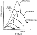
Вышеуказанная секция 15 диффузора выполнена между выходом 14 рабочего колеса и секцией 16 спиральной камеры и представляет собой канал для восстановления статического давления за счет уменьшения расхода воздуха, выходящего из выхода 14 рабочего колеса. При необходимости секция 15 диффузора оснащена лопатками. При наличии лопаток в секции 15 диффузора, как показано на фиг.15, возможно изменение рабочего диапазона центробежного компрессора. Иначе говоря, при наличии лопаток в секции 15 диффузора линия помпажа, указывающая на возникновение помпажа, может быть смещена в сторону высокой степени сжатия и низкого расхода. В данном случае термин «помпаж» обозначает явление изменения давления и расхода, когда центробежный компрессор входит в режим автоколебаний и выпускает сжатый воздух в особых циклах, что определяет эксплуатационный предел в области низкого расхода.The above-mentioned
[0004][0004]
Центробежный компрессор, применяемый в автомобильном турбокомпрессоре, работает при различном числе оборотов, что требует широкого рабочего диапазона. Однако при понижении расхода в центробежном компрессоре в секции 15 диффузора возникает вышеуказанный помпаж. С другой стороны, когда расход возрастает, возникает непроходимость текучей среды, так называемое «запирание потока», у рабочего колеса или внутри секции диффузора, при этом диапазон расхода ограничен со стороны высокого расхода.The centrifugal compressor used in the automobile turbocharger operates at various speeds, which requires a wide operating range. However, as the flow rate decreases in the centrifugal compressor in the
[0005][0005]
Из уровня техники известно техническое решение для расширения рабочего диапазона центробежного компрессора с созданием паза 25 и циркуляционного канала 26 на корпусе 21, как показано на фиг.16 (см., например, патентный документ [1]).The prior art knows a technical solution for expanding the operating range of a centrifugal compressor with the creation of a
Известно техническое решение, обеспечивающее расширение рабочего диапазона центробежного компрессора за счет применения регулирующего механизма, такого как регулируемое направляющее крыло или регулируемый диффузор (см., например, патентные документы [2], [3], [4] и [5]). Более конкретно, регулируемый диффузор может изменять площадь канала посредством вращения или скользящего перемещения лопатки 28 диффузора, как показано на фиг.17А и 17В, и может расширять рабочий диапазон центробежного компрессора. В частности, в регулируемом диффузоре, показанном на фиг.17В, рабочий диапазон расширяется за счет изменения углового положения лопаток диффузора в соответствии со скоростью потока газа, выходящего из рабочего колеса 13.A technical solution is known that provides the extension of the working range of a centrifugal compressor through the use of a regulating mechanism, such as an adjustable guide wing or an adjustable diffuser (see, for example, patent documents [2], [3], [4] and [5]). More specifically, the adjustable diffuser can change the area of the channel by rotating or slidingly moving the
Патентный документ [1]: публикация № Hei 10-176699 японской патентной заявки.Patent Document [1]: Japanese Patent Application Publication No. Hei 10-176699.
Патентный документ [2]: публикация № Hei 11-173300 японской патентной заявки.Patent Document [2]: Japanese Patent Application Publication No. Hei 11-173300.
Патентный документ [3]: публикация №2001-329995 японской патентной заявки.Patent Document [3]: Japanese Patent Application Publication No. 2001-329995.
Патентный документ [4]: публикация №2001-329996 японской патентной заявки.Patent Document [4]: Japanese Patent Application Publication No. 2001-329996.
Патентный документ [5]: патент №3038398.Patent document [5]: patent No. 3038398.
Сущность изобретенияSUMMARY OF THE INVENTION
[0006][0006]
Однако техническое решение, раскрытое в патентном документе [1], имеет недостатки, поскольку не обеспечивает значительного улучшения, несмотря на некоторое расширение рабочего диапазона центробежного компрессора за счет обработки корпуса, как показано на фиг.18. Недостаток технических решений, раскрытых в патентных документах [2], [3], [4] и [5], заключается в экономической неэффективности, поскольку регулируемый диффузор требует сложного приводного устройства. Кроме того, поскольку между лопаткой 28 диффузора и стенкой секции диффузора 15 имеется подвижный участок, возникают проблемы, которые заключаются в низкой надежности устойчивой работы, а также в утечке газа через зазор у подвижного участка, что ухудшает эксплуатационные свойства.However, the technical solution disclosed in the patent document [1] has drawbacks because it does not provide a significant improvement, despite some expansion of the working range of the centrifugal compressor due to the processing of the housing, as shown in Fig. 18. The disadvantage of the technical solutions disclosed in patent documents [2], [3], [4] and [5] is economic inefficiency, since the adjustable diffuser requires a complex drive unit. In addition, since there is a movable section between the
[0007][0007]
С учетом вышесказанного целью заявленного изобретения является обеспечение центробежного компрессора с широким рабочим диапазоном, эффективного с экономической точки зрения и обладающего высокой надежностью в отношении устойчивой работы.In view of the foregoing, the aim of the claimed invention is to provide a centrifugal compressor with a wide operating range, economically efficient and highly reliable in relation to stable operation.
[0008][0008]
Для решения вышеуказанных задач в заявленном изобретении предложено следующее.To solve the above problems, the claimed invention proposed the following.
Центробежный компрессор согласно заявленному изобретению представляет собой центробежный компрессор, имеющий ось вращения, рабочее колесо, установленное на оси вращения, корпус, вмещающий рабочее колесо, секцию диффузора, соединенную с выходом рабочего колеса, и секцию спиральной камеры, соединенную с выходом диффузора, и предназначенный для сжатия текучей среды под воздействием центробежной силы, возникающей при вращении рабочего колеса, данный компрессор также содержит: разделительный элемент, разделяющий проходной канал секции диффузора и секции спиральной камеры на несколько каналов по направлению движения текучей среды с образованием проходного канала со стороны ступицы и проходного канала со стороны бандажа; а также регулятор расхода, который при низком расходе текучей среды, сжатой рабочим колесом, обеспечивает уменьшение расхода текучей среды в проходном канале со стороны бандажа и высокий расход текучей среды в проходном канале со стороны ступицы, а при высоком расходе текучей среды, сжатой рабочим колесом, обеспечивает поток текучей среды и в проходной канал со стороны бандажа, и в проходной канал со стороны ступицы, без уменьшения расхода текучей среды в проходном канале со стороны бандажа.The centrifugal compressor according to the claimed invention is a centrifugal compressor having an axis of rotation, an impeller mounted on an axis of rotation, a housing accommodating an impeller, a diffuser section connected to the outlet of the impeller, and a scroll chamber section connected to the diffuser outlet and designed to compression of the fluid under the influence of centrifugal force arising from the rotation of the impeller, this compressor also contains: a separation element that separates the passage channel of the di fuser and sections of the spiral chamber into several channels in the direction of movement of the fluid with the formation of the passage channel from the hub and the passage channel from the side of the bandage; as well as a flow regulator, which with a low flow rate of the fluid compressed by the impeller ensures a decrease in the flow rate of the fluid in the passage channel from the side of the brace and a high flow rate of the fluid in the passage passage from the hub side, and at a high flow rate of the fluid compressed by the impeller, provides a fluid flow to both the passage channel from the bandage side and the passage channel from the hub side, without reducing the flow rate of the fluid in the passage channel from the bandage side.
[0009][0009]
В данном центробежном компрессоре сжатая рабочим колесом текучая среда на выходе из рабочего колеса имеет большую неравномерность скоростей со стороны ступицы. При низком расходе неравномерность скоростей потока является особенно значительной. Поэтому имеется регулятор расхода для снижения расхода текучей среды в проходном канале со стороны бандажа и обеспечения протекания текучей среды в канале со стороны ступицы, когда расход текучей среды, сжатой рабочим колесом, является низким. Соответственно, при низком расходе для подвода значительного объема текучей среды к проходному каналу со стороны ступицы создают маленький выпускной канал, что предотвращает возникновение помпажа, означающего эксплуатационный предел в области низких расходов. Напротив, когда расход текучей среды, сжатой рабочим колесом, является высоким, регулятор расхода обеспечивает протекание текучей среды как в проходном канале со стороны бандажа, так и в проходном канале со стороны ступицы. Соответственно, для предотвращения запирания потока, означающего эксплуатационный предел в области высоких расходов, создают большой выпускной канал. Таким образом, за счет предотвращения помпажа и запирания потока обеспечивается широкий рабочий диапазон компрессора.In this centrifugal compressor, the fluid compressed by the impeller at the outlet of the impeller has a large velocity unevenness on the hub side. At low flow rates, uneven flow rates are especially significant. Therefore, there is a flow regulator to reduce the flow rate of the fluid in the passage channel from the bandage side and to allow the flow of fluid in the passage from the hub side when the flow rate of the fluid compressed by the impeller is low. Accordingly, at a low flow rate, a small exhaust channel is created to supply a significant amount of fluid to the passage channel from the hub side, which prevents surge occurrence, indicating an operational limit in the low flow area. On the contrary, when the flow rate of the fluid compressed by the impeller is high, the flow regulator allows fluid to flow both in the passage channel from the bandage side and in the passage channel from the hub side. Accordingly, in order to prevent blocking of the flow, signifying an operational limit in the high flow area, a large outlet channel is created. Thus, by preventing surge and blocking the flow, a wide compressor operating range is ensured.
В центробежном компрессоре согласно заявленному изобретению при низких затратах обеспечивается широкий рабочий диапазон по сравнению с регулируемым диффузором, который требует сложного приводного механизма. Кроме того, поскольку количество элементов, составляющих узел привода, может быть уменьшено, обеспечивается высокая надежность эксплуатации. Кроме того, поскольку отсутствует утечка газа через зазор у подвижного участка, как в случае с регулируемым диффузором, не возникает ухудшения эксплуатационных свойств, связанного с утечкой газа.In the centrifugal compressor according to the claimed invention at a low cost provides a wide operating range compared to an adjustable diffuser, which requires a complex drive mechanism. In addition, since the number of elements making up the drive assembly can be reduced, high operational reliability is ensured. In addition, since there is no gas leakage through the gap at the moving portion, as in the case of an adjustable diffuser, there is no deterioration in the operational properties associated with gas leakage.
[0010][0010]
Предпочтительно, разделительный элемент в центробежном компрессоре является разделительной стенкой, выполненной внутри секции диффузора и секции спиральной камеры.Preferably, the spacer element in the centrifugal compressor is a spacer wall formed within the diffuser section and the scroll chamber section.
[0011][0011]
В вышеуказанном центробежном компрессоре нужно просто разделить проходной канал разделительной стенкой, при этом разделение проходных каналов секции диффузора и секции спиральной камеры легко выполнимо с низкими затратами.In the aforementioned centrifugal compressor, it is simply necessary to divide the passage channel with a dividing wall, while separating the passage channels of the diffuser section and the scroll chamber section is easily feasible at low cost.
[0012][0012]
Предпочтительно, регулятор расхода в данном центробежном компрессоре представляет собой регулирующий расход клапан, выполненный возле выходного участка секции спиральной камеры.Preferably, the flow regulator in this centrifugal compressor is a flow control valve made near the outlet section of the scroll chamber section.
[0013][0013]
В заявленном центробежном компрессоре за счет постоянного регулирования расхода текучей среды, протекающей в соответствующих проходных каналах, достигается широкий рабочий диапазон компрессора при отсутствии помпажа и запирания потока.In the inventive centrifugal compressor due to the constant regulation of the flow rate of the fluid flowing in the respective passage channels, a wide operating range of the compressor is achieved in the absence of surging and blocking the flow.
Регулирующий расход клапан, предпочтительно, выполнен в проходном канале со стороны бандажа. В этом случае проходной канал со стороны бандажа полностью закрывается при низком расходе и полностью открывается при высоком расходе. При расходе, промежуточном между низким и высоким расходом, отверстие проходного канала со стороны бандажа может находиться в промежуточном положении между полностью закрытым и полностью открытым.The flow control valve is preferably provided in the passageway from the bandage side. In this case, the passage channel from the side of the bandage completely closes at low flow rate and fully opens at high flow rate. When the flow rate is intermediate between low and high flow rate, the opening of the passage channel from the side of the bandage may be in the intermediate position between fully closed and fully open.
[0014][0014]
Предпочтительно, диаметр по меньшей мере одного из входов секции диффузора в центробежном компрессоре составляет от 1,02 до 1,2 диаметра рабочего колеса.Preferably, the diameter of at least one of the inlets of the diffuser section in the centrifugal compressor is from 1.02 to 1.2 times the diameter of the impeller.
[0015][0015]
Если диаметр входа секции диффузора меньше, чем 1,02 диаметра рабочего колеса, то разделительная стенка и поток на выходе из рабочего колеса наталкиваются друг на друга, следовательно, при этом снижаются эксплуатационные свойства. Если диаметр входа секции диффузора больше, чем 1,2 диаметра рабочего колеса, снижается восстановление давления в диффузоре. Таким образом, диаметр входа диффузора задан в пределах от 1,02 до 1,2 диаметра рабочего колеса.If the inlet diameter of the diffuser section is less than 1.02 of the diameter of the impeller, then the dividing wall and the flow at the outlet of the impeller run into each other, therefore, performance is reduced. If the inlet diameter of the diffuser section is larger than 1.2 of the impeller diameter, the pressure recovery in the diffuser is reduced. Thus, the diameter of the inlet of the diffuser is set in the range from 1.02 to 1.2 of the diameter of the impeller.
[0016][0016]
Предпочтительно, торцевая поверхность разделительной стенки со стороны набегания потока имеет наклон от стороны ступицы к стороне бандажа.Preferably, the end surface of the dividing wall on the upstream side has a slope from the hub side to the bandage side.
[0017][0017]
Неравномерность скоростей текучей среды, выходящей из рабочего колеса, не является симметричной со стороны бандажа и со стороны ступицы и имеет наклон по направлению к стороне ступицы. Следовательно, торцевую поверхность разделительной стенки со стороны набегания потока выполняют с наклоном от стороны ступицы к стороне бандажа. Соответственно, на торцевой поверхности разделительной стенки отсутствует разделение и обеспечивается равномерный поток.The uneven velocity of the fluid exiting the impeller is not symmetrical on the bandage side and on the hub side and has an inclination towards the hub side. Therefore, the end surface of the dividing wall from the side of the flow inlet is performed with an inclination from the side of the hub to the side of the bandage. Accordingly, there is no separation on the end surface of the partition wall and a uniform flow is ensured.
[0018][0018]
Предпочтительно, по меньшей мере одна из секций диффузора в центробежном компрессоре содержит лопатку.Preferably, at least one of the diffuser sections in the centrifugal compressor comprises a blade.
[0019][0019]
В центробежном компрессоре согласно заявленному изобретению при низком расходе текучей среды высокую степень сжатия получают за счет обеспечения циркуляции текучей среды в секции диффузора с лопаткой, который оснащен лопаткой таким образом, что помпаж не возникает. При высоком расходе текучей среды запирание потока предотвращается за счет приведения в действия регулятора расхода, обеспечивающего проход текучей среды также через секцию диффузора без лопатки. Следовательно, при такой конструкции обеспечивается широкий рабочий диапазон без возникновения помпажа или запирания потока. Поскольку секция диффузора с лопаткой не имеет подвижного участка и, следовательно, не возникает утечки газа через зазор, то не происходит связанного с утечкой газа ухудшения эксплуатационных свойств.In a centrifugal compressor according to the claimed invention, at a low flow rate of the fluid, a high compression ratio is obtained by circulating the fluid in the section of the diffuser with a blade, which is equipped with a blade so that surge does not occur. With a high flow rate of the fluid, flow blocking is prevented by the actuation of the flow controller, which allows the passage of the fluid also through the diffuser section without a blade. Therefore, with this design, a wide operating range is provided without causing surge or blocking of the flow. Since the section of the diffuser with the blade does not have a movable section and, therefore, there is no gas leakage through the gap, there is no degradation in performance associated with gas leakage.
[0020][0020]
Предпочтительно, площадь поперечного сечения проходного канала секции диффузора с лопаткой в центробежном компрессоре меньше, чем площади поперечных сечений проходных каналов других секций диффузора.Preferably, the cross-sectional area of the passage channel of the diffuser section with the blade in the centrifugal compressor is smaller than the cross-sectional area of the passage channels of the other sections of the diffuser.
[0021][0021]
Для центробежного компрессора согласно заявленному изобретению рабочий диапазон компрессора может быть расширен, поскольку высокую степень сжатия при низком расходе текучей среды получают за счет обеспечения движения текучей среды в секции диффузора с лопаткой.For a centrifugal compressor according to the claimed invention, the operating range of the compressor can be expanded, since a high compression ratio at a low flow rate of the fluid is obtained by ensuring the movement of the fluid in the section of the diffuser with a blade.
[0022][0022]
Так как в центробежном компрессоре согласно изобретению проходные каналы секции диффузора и секции спиральной камеры разделены на проходные каналы со стороны ступицы и проходные каналы со стороны бандажа, причем соответствующие проходные каналы используют надлежащим образом в зависимости от расхода текучей среды, выходящей из рабочего колеса, то обеспечивается широкий рабочий диапазон при низких затратах. Кроме того, поскольку подвижный участок может быть уменьшен по сравнению с регулируемым диффузором, центробежный компрессор будет иметь высокую степень надежности.Since in the centrifugal compressor according to the invention the passage channels of the diffuser section and the spiral chamber section are divided into passage channels from the hub side and passage channels from the bandage side, the corresponding passage channels being used appropriately depending on the flow rate of the fluid leaving the impeller, it is ensured wide operating range at low cost. In addition, since the movable portion can be reduced in comparison with the adjustable diffuser, the centrifugal compressor will have a high degree of reliability.
Краткое описание чертежейBrief Description of the Drawings
[0023][0023]
На фиг.1А представлен вертикальный разрез центробежного компрессора в соответствии с первым вариантом реализации заявленного изобретения;On figa presents a vertical section of a centrifugal compressor in accordance with the first embodiment of the claimed invention;
на фиг.1В показан в увеличенном масштабе фрагмент выхода из рабочего колеса центробежного компрессора, показанного на фиг.1;on figv shows on an enlarged scale a fragment of the exit of the impeller of the centrifugal compressor shown in figure 1;
на фиг.2 представлен вертикальный разрез основной части центробежного компрессора, показанного на фиг.1;figure 2 presents a vertical section of the main part of the centrifugal compressor shown in figure 1;
на фиг.3А представлен в увеличенном масштабе фрагмент участка разделительной стенки центробежного компрессора, показанного на фиг.2;on figa presents on an enlarged scale a fragment of a portion of the separation wall of the centrifugal compressor shown in figure 2;
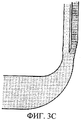
фиг.3В является поясняющим чертежом, иллюстрирующим состояние движения текучей среды в центробежном компрессоре, показанном на фиг.2;FIG. 3B is an explanatory drawing illustrating a state of fluid movement in the centrifugal compressor shown in FIG. 2;
фиг.3С является поясняющим чертежом, иллюстрирующим состояние движения текучей среды в центробежном компрессоре, известном из области техники;3C is an explanatory drawing illustrating a state of fluid movement in a centrifugal compressor known in the art;
на фиг.4А представлен вертикальный разрез, иллюстрирующий состояние движения текучей среды при низком расходе в центробежном компрессоре, показанном на фиг.2;on figa presents a vertical section illustrating the state of motion of the fluid at low flow rate in the centrifugal compressor shown in figure 2;
на фиг.4В представлен вертикальный разрез, иллюстрирующий состояние движения текучей среды при высоком расходе в центробежном компрессоре, показанном на фиг.2;on figv presents a vertical section illustrating the state of motion of the fluid at high flow rate in the centrifugal compressor shown in figure 2;
на фиг.5 представлена графическая зависимость между степенью сжатия и расходом в центробежном компрессоре, показанном на фиг.2;figure 5 presents a graphical relationship between the compression ratio and flow rate in the centrifugal compressor shown in figure 2;
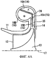
на фиг.6А представлен вертикальный разрез модификации центробежного компрессора, показанного на фиг.2;on figa presents a vertical section of a modification of the centrifugal compressor shown in figure 2;
на фиг.6В представлен вертикальный разрез модификации центробежного компрессора, показанного на фиг.2;on figv presents a vertical section of a modification of the centrifugal compressor shown in figure 2;
на фиг.7 представлен вертикальный разрез центробежного компрессора согласно второму варианту реализации заявленного изобретения;Fig.7 shows a vertical section of a centrifugal compressor according to a second embodiment of the claimed invention;
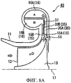
на фиг.8А представлен вертикальный разрез, иллюстрирующий состояние движения текучей среды при низком расходе в центробежном компрессоре, показанном на фиг.7;on figa presents a vertical section illustrating the state of motion of the fluid at a low flow rate in the centrifugal compressor shown in Fig.7;
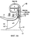
на фиг.8В представлен вертикальный разрезе, иллюстрирующий состояние движения текучей среды при высоком расходе в центробежном компрессоре, показанном на фиг.7;on figv presents a vertical section illustrating the state of motion of the fluid at high flow rate in the centrifugal compressor shown in Fig.7;
на фиг.9 представлена графическая зависимость между степенью сжатия и расходом в центробежном компрессоре, показанном на фиг.7;figure 9 presents a graphical relationship between the compression ratio and flow rate in the centrifugal compressor shown in figure 7;
на фиг.10 представлен вертикальный разрез центробежного компрессора согласно третьему варианту реализации заявленного изобретения;figure 10 presents a vertical section of a centrifugal compressor according to a third embodiment of the claimed invention;
на фиг.11А представлен вертикальный разрез, иллюстрирующий состояние движения текучей среды при низком расходе в центробежном компрессоре, показанном на фиг.10;on figa presents a vertical section illustrating the state of motion of the fluid at low flow rate in the centrifugal compressor shown in figure 10;
на фиг.11В представлен вертикальный разрез, иллюстрирующий состояние движения текучей среды при высоком расходе в центробежном компрессоре, показанном на фиг.10;on figv presents a vertical section illustrating the state of motion of the fluid at high flow rate in the centrifugal compressor shown in Fig.10;
на фиг.12 представлена графическая зависимость между степенью сжатия и расходом в центробежном компрессоре, показанном на фиг.10;on Fig presents a graphical relationship between the compression ratio and flow rate in the centrifugal compressor shown in Fig.10;
на фиг.13 представлена основная часть центробежного компрессора, известного из уровня техники;on Fig presents the main part of a centrifugal compressor, known from the prior art;
на фиг.14 представлен вертикальный разрез центробежного компрессора, известного из уровня техники;on Fig presents a vertical section of a centrifugal compressor, known from the prior art;
на фиг.15 представлена графическая зависимость между степенью сжатия и расходом в центробежном компрессоре, известном из уровня техники;on Fig presents a graphical relationship between the compression ratio and flow rate in a centrifugal compressor, known from the prior art;
на фиг.16 представлен вертикальный разрез центробежного компрессора, известного из уровня техники;on Fig presents a vertical section of a centrifugal compressor, known from the prior art;
на фиг.17А представлен вертикальный разрез центробежного компрессора, известного из уровня техники;on figa presents a vertical section of a centrifugal compressor, known from the prior art;
на фиг.17В представлен вертикальный разрез центробежного компрессора, известного из уровня техники; иon figv presents a vertical section of a centrifugal compressor, known from the prior art; and
на фиг.18 представлена графическая зависимость между степенью сжатия и расходом в центробежном компрессоре, известном из уровня техники.on Fig presents a graphical relationship between the compression ratio and flow rate in a centrifugal compressor, known from the prior art.
[0024][0024]
Номера позиций:Item Numbers:
10, 30, 40, 50 - центробежный компрессор;10, 30, 40, 50 - centrifugal compressor;
11 - корпус;11 - case;
13 - рабочее колесо;13 - the impeller;
15, 15А, 15В - секция диффузора;15, 15A, 15B - section of the diffuser;
16, 16А, 16В - секция спиральной камеры;16, 16A, 16B - section of the spiral chamber;
17 - ось вращения;17 - axis of rotation;
35 - лопатка;35 - scapula;
36 - клапан, регулирующий расход;36 - valve that controls the flow;
37 - разделительная стенка;37 - dividing wall;
А - проходной канал со стороны ступицы;A - passage channel from the hub;
В - проходной канал со стороны бандажа.In - the passage channel from the bandage.
Предпочтительные варианты реализацииPreferred Embodiments
[0025][0025]
Первый вариант реализацииThe first implementation option
Далее приведено описание первого варианта реализации заявленного изобретения со ссылкой на чертежи.The following is a description of a first embodiment of the claimed invention with reference to the drawings.
На фиг.1А показан вертикальный разрез центробежного компрессора 30 согласно первому варианту реализации. На фиг.1В показано распределение скоростей потока на выходе из рабочего колеса.On figa shows a vertical section of a centrifugal compressor 30 according to the first embodiment. On figv shows the distribution of flow rates at the exit of the impeller.
Центробежный компрессор 30, показанный на фиг.1А содержит рабочее колесо 13 оснащенное рядом лопастей 12, и корпус 11, вмещающий рабочее колесо 13.The centrifugal compressor 30 shown in FIG. 1A comprises an
Рабочее колесо 13 приводится во вращение вокруг оси 17 посредством приводного устройства, например двигателя или турбины (не показаны). За выходом из рабочего колеса 13 непрерывно следуют секция 15 диффузора и секция 16 спиральной камеры.The
В секции 15 диффузора уменьшается скорость потока воздуха, поступающего от наружного периферического конца рабочего колеса 13, вращающегося в корпусе 11, и восстанавливается статическое давление.In the
Секция 16 спиральной камеры соединена с секцией 15 диффузора ниже по потоку и содержит спиралевидный канал. Далее по потоку за секцией 16 спиральной камеры выполнена выпускная труба 38, по которой проходит текучая среда, прошедшая через секцию 16 спиральной камеры.
[0026][0026]
Внутри секции 15 диффузора, секции 16 спиральной камеры и выпускной трубы 38 выполнена разделительная стенка 37 (разделительный элемент), разделяющая канал на части в направлении движения текучей среды с формированием проходного канала со стороны ступицы (канал А) и проходного канала со стороны бандажа (канал В). Текучая среда, выходящая из рабочего колеса 13 ближе к ступице (правая сторона на чертеже), входит в канал со стороны ступицы, а текучая среда, выходящая из рабочего колеса 13 ближе к бандажу (левая сторона на чертеже), входит в канал со стороны бандажа.Inside
Разделительная стенка 37 выполнена из тонкой пластины, а площадь поперечного сечения секции 15 диффузора увеличивается на величину, соответствующую разделительной стенке 37. Посредством такой разделительной стенки 37 каналы секции 15 диффузора и секции 16 спиральной камеры несложно разделить при низких затратах.The dividing
[0027][0027]
Секция 15А диффузора со стороны ступицы оснащена лопатками 35. Множество лопаток 35 расположено по окружности с заданным интервалом и прикреплено к корпусу. Иначе говоря, угол лопаток 35 относительно текучей среды является постоянным. Площадь поперечного сечения проходного канала со стороны бандажа секции 15В диффузора превышает площадь поперечного сечения (площадь горловины) проходного канала со стороны ступицы секции 15А диффузора. Это предусмотрено для расширения рабочего диапазона при высоком расходе. Более конкретно, значение SA/RA, предпочтительно, меньше, чем SB/RB, где SA - площадь бокового сечения секции 16А спиральной камеры со стороны ступицы, RA - расстояние от центра секции 16А спиральной камеры со стороны ступицы (центр бокового сечения) до оси 17 вращения, SB - площадь бокового сечения секции 16В спиральной камеры со стороны бандажа, и RB - расстояние от центра секции 16В спиральной камеры со стороны бандажа (центр бокового сечения) до оси 17 вращения.The
[0028][0028]
В выпускной трубе 38В со стороны бандажа выполнен регулирующий расход клапан 36 (регулятор расхода), регулирующий расходы в соответствующих проходных каналах. В первом варианте реализации в качестве регулирующего расход клапана 36 используется клапан-бабочка. При использовании клапана 36 в качестве регулятора расхода обеспечивается стабильное регулирование расходов с высокой степенью точности в соответствующих проходных каналах. Для снижения статической нагрузки регулирующий расход клапан 36, предпочтительно, установлен как можно ближе к секции 16 спиральной камеры.In the
[0029][0029]
Как показано на фиг.2, диаметр вxoда 14 секции диффузора лежит в диапазоне от 1,02 до 1,2 наружного диаметра рабочего колеса.As shown in figure 2, the diameter of the
Как показано на фиг.3А, торцевая поверхность конца разделительной стенки 37 имеет наклон вверх по потоку от стороны ступицы к стороне бандажа. Такое решение предусмотрено для равномерной подачи текучей среды в проходной канал А со стороны ступицы и в проходной канал В со стороны бандажа при высоком расходе текучей среды.As shown in FIG. 3A, the end surface of the end of the dividing
На фиг.3В и 3С представлены результаты, иллюстрирующие режимы потока, обусловленные разницей в направлении наклона разделительной стенки, полученные методами вычислительной гидродинамики. Фиг.3В иллюстрирует случай, когда разделительная стенка наклонена от стороны ступицы к стороне бандажа, как показано на фиг.3А, при этом текучая среда равномерно распределяется по проходному каналу А со стороны ступицы и по проходному каналу В со стороны бандажа. С другой стороны, как показано на фиг.3С, в случае, когда разделительная стенка наклонена от стороны бандажа к стороне ступицы, текучая среда отклоняется в сторону ступицы. Таким образом, в первом варианте реализации используется разделительная стенка с торцом в форме, показанной на фиг.3А.On figv and 3C presents the results illustrating the flow regimes due to the difference in the direction of inclination of the dividing wall, obtained by methods of computational fluid dynamics. FIG. 3B illustrates a case where the dividing wall is inclined from the hub side to the band side, as shown in FIG. 3A, wherein the fluid is evenly distributed along the passage channel A from the hub side and along the passage channel B from the band side. On the other hand, as shown in FIG. 3C, in the case where the dividing wall is inclined from the side of the brace to the side of the hub, the fluid deviates toward the hub. Thus, in the first embodiment, a dividing wall with an end face in the form shown in FIG. 3A is used.
[0030][0030]
Далее приводится описание работы центробежного компрессора 30 с вышеописанной конструкцией.The following is a description of the operation of the centrifugal compressor 30 with the above construction.
В центробежном компрессоре 30 рабочее колесо 13 приводится во вращение вокруг оси 17 посредством приводного устройства, например двигателя или турбины (не показаны). При вращении рабочего колеса 13 текучая среда, входящая через вход подачи воздуха (не показано), поступает внутрь корпуса 11. Текучая среда, поступившая в корпус 11, подвергается воздействию центробежной силы, создаваемой вращением рабочего колеса 13, с соответствующим сжатием, последовательно проходит через вход 14 секции диффузора, секцию 15 диффузора, секцию 16 спиральной камеры и выпускную трубу 38, и выходит в виде сжатой текучей среды через выпускное отверстие (не показано).In the centrifugal compressor 30, the
[0031][0031]
При работе клапана 36 регулируются расходы в соответствующих проходных каналах.During operation of the
При низком расходе сжатой рабочим колесом 13 текучей среды отверстие регулирующего расход клапана 36 сужается, обеспечивая уменьшение расхода текучей среды, протекающей в проходном канале В потока со стороне бандажа, как показано на фиг.4А, при этом текучая среда протекает в канале А со стороны ступицы с более высоким расходом. Иначе говоря, сжатая текучая среда последовательно проходит через вход 14 секции диффузора, секцию 15А диффузора с лопатками 35 и секцию 16А спиральной камеры.At a low flow rate of the fluid compressed by the
Напротив, при высоком расходе сжатой рабочим колесом 13 текучей среды отверстие регулирующего расход клапана 36 увеличивается, обеспечивая протекание текучей среды в проходном канале В со стороны бандажа и в проходном канале А со стороны ступицы без уменьшения расхода текучей среды в канале В со стороны бандажа, как показано на фиг.4В. Иначе говоря, сжатая текучая среда разветвляется у входа 14 секции диффузора и проходит через проходной канал секции 15А диффузора с лопатками 35 в секцию 16А спиральной камеры и через проходной канал секции диффузора 15В без лопаток в секцию 16В спиральной камеры.In contrast, with a high flow rate of the fluid compressed by the
В этом случае отверстие регулирующего расход клапана 36 не будет полностью открыто или закрыто, но, предпочтительно, оно может быть отрегулировано до такого промежуточного отверстия, которое обеспечивает высокую степень сжатия относительно расхода сжатой текучей среды.In this case, the orifice of the
[0032][0032]
На фиг.5 показана зависимость между расходом и степенью сжатия текучей среды в центробежном компрессоре в соответствии с первым вариантом выполнения.5 shows the relationship between flow rate and compression ratio of a fluid in a centrifugal compressor in accordance with a first embodiment.
Как следует из фиг.5, при низком расходе сжатой текучей среды высокую степень сжатия получают за счет снижения расхода текучей среды в проходном канале В со стороны бандажа и обеспечения высокого расхода текучей среды в проходном канале А со стороны ступицы. Иначе говоря, линия помпажа сдвигается в сторону низкого расхода и высокой степени сжатия. Следует также понимать, что при высоком расходе сжатой текучей среды он распределяется с протеканием текучей среды в проходном канале В со стороны бандажа и в проходном канале А со стороны ступицы без снижения расхода текучей среды в проходном канале В со стороны бандажа.As follows from figure 5, with a low flow rate of compressed fluid, a high compression ratio is obtained by reducing the flow rate of the fluid in the passage channel B from the side of the brace and ensuring a high flow rate of the fluid in the passage channel A from the hub side. In other words, the surge line shifts toward low flow and high compression. It should also be understood that with a high flow rate of compressed fluid, it is distributed with the flow of fluid in the passage channel B from the side of the brace and in the passage channel A from the hub side without reducing the flow rate of the fluid in the passage channel B from the side of the brace.
[0033][0033]
В данном центробежном компрессоре текучая среда, сжатая рабочим колесом, за счет центробежной силы имеет значительное распределение скоростей со стороны ступицы у выхода из рабочего колеса. Следовательно, регулирующий расход клапан 36 выполняется в проходном канале В со стороны бандажа, таким образом, при малом расходе сжатой рабочим колесом 13 текучей среды за счет работы регулирующего расход клапана 36 расход текучей среды в проходном канале В со стороны бандажа снижается, а в проходном канале А со стороны ступицы возрастает. Таким образом, формируется небольшой выпускной канал и, соответственно, при низком расходе в проходной канал А со стороны ступицы поступает большой объем текучей среды, помпаж при этом не возникает.In this centrifugal compressor, the fluid compressed by the impeller, due to the centrifugal force, has a significant velocity distribution on the hub side at the exit of the impeller. Therefore, the
Напротив, при высоком расходе сжатой рабочим колесом 13 текучей среды, текучая среда за счет работы клапана 36 протекает как в проходном канале В со стороны бандажа, так и в проходном канале А со стороны ступицы без уменьшения расхода текучей среды в проходном канале В. Соответственно, обеспечивается большой выпускной канал и предотвращается запирание потока.On the contrary, with a high flow rate of the fluid compressed by the
Таким образом, предотвращается возникновение помпажа и запирания потока и обеспечивается широкий рабочий диапазон компрессора за счет использования при низком расходе только проходного канала А со стороны ступицы и за счет использования при высоком расходе проходного канала А со стороны ступицы и проходного канала В со стороны бандажа.Thus, the occurrence of surging and blocking of the flow is prevented and a wide compressor operating range is ensured due to the use of only the passage channel A from the hub side at a low flow rate and due to the use of the passage channel A from the hub side and the passage channel B from the bandage at high flow rate.
[0034][0034]
Как раскрыто выше, в центробежном компрессоре согласно первому варианту реализации легко предотвращается возникновение помпажа и запирания потока по сравнению с регулируемым диффузором, требующим сложного приводного устройства, и достигается широкий рабочий диапазон. Кроме того, уменьшение количества компонентов приводного устройства обеспечивает высокую надежность работы. Также предотвращается ухудшение эксплуатационных свойств, возникающее из-за утечки газа через зазор у подвижного участка.As disclosed above, in the centrifugal compressor according to the first embodiment, the occurrence of surging and blocking of the flow is easily prevented compared to an adjustable diffuser requiring a complex drive device, and a wide operating range is achieved. In addition, reducing the number of components of the drive device provides high reliability. Also, deterioration in performance due to gas leakage through the gap at the moving portion is prevented.
[0035][0035]
Как показано на фиг.6А и 6В, разделительная стенка 37, разделяющая на части секцию 15 диффузора и секцию спиральной камеры 16, может быть выполнена с наклоном относительно оси 17 вращения или под прямым углом к ней.As shown in FIGS. 6A and 6B, the dividing
Кроме того, можно выполнить элемент стенки (не показан), который съемным образом можно вставлять в секцию 15В диффузора вместо регулирующего расход клапана 36 так, чтобы регулировать расход в проходном канале В со стороны бандажа и в проходном канале А со стороны ступицы.In addition, it is possible to provide a wall element (not shown), which can be removably inserted into the
Несмотря на то, что в первом варианте реализации показана конструкция, в которой лопатки 35 выполнены только в секции 15А диффузора со стороны ступицы, тем не менее, также допустима конструкция, в которой лопатки выполнены только в секции 15В диффузора со стороны бандажа. При такой конструкции достигается расширение рабочего диапазона данного центробежного компрессора.Although the first embodiment shows a design in which the
[0036][0036]
Второй вариант реализацииSecond implementation option
Далее со ссылкой на фиг.7 раскрыт второй вариант реализации заявленного изобретения.Next, with reference to FIG. 7, a second embodiment of the claimed invention is disclosed.
Центробежный компрессор согласно второму варианту реализации отличается от центробежного компрессора согласно первому варианту реализации тем, что лопатки выполнены как в секции 15А диффузора со стороны ступицы, так и в секции 15В диффузора со стороны бандажа. Центробежный компрессор согласно второму варианту реализации будет рассмотрен в основном с точки зрения отличия от первого варианта, при этом описания моментов, которые являются общими с первым вариантом выполнения, опущены.The centrifugal compressor according to the second embodiment differs from the centrifugal compressor according to the first embodiment in that the blades are made both in the
[0037][0037]
Как показано на фиг.7, секция 15А диффузора со стороны ступицы и секция 15В диффузора со стороны бандажа оснащены лопатками 35, которые расположены по окружности с заданными интервалами и прикреплены к корпусу 11.As shown in FIG. 7, the hub-
Количество лопаток 35А, установленных в секции 15А диффузора со стороны ступицы, превышает количество лопаток 35В, установленных в секции 15В диффузора со стороны бандажа. Соответственно, площадь сечения проходного канала секции 15А диффузора со стороны ступицы меньше площади сечения проходного канала секции 15В диффузора со стороны бандажа. Также можно задать меньшую высоту или угловое расположение лопаток 35А, установленных в секции 15А диффузора со стороны ступицы, чем у лопаток 35В, установленных в секции 15В диффузора со стороны бандажа. Соответственно, можно задать площадь поперечного сечения проходного канала секции 15А диффузора со стороны ступицы меньшей, чем площадь поперечного сечения проходного канала секции 15В диффузора со стороны бандажа, как в вышеописанном случае.The number of
Регулирующий расход клапан 36 (регулятор расхода), обеспечивающий регулирование расходов в соответствующих проходных каналах, выполнен в выпускной трубе 38В со стороны бандажа.The flow control valve 36 (flow regulator), providing flow control in the respective passage channels, is made in the
[0038][0038]
В центробежном компрессоре 40, имеющем вышеописанную конструкцию, расходы в соответствующих проходных каналах регулируются работой клапана 36.In the
При низком расходе текучей среды, сжатой рабочим колесом 13, отверстие регулирующего расход клапана 36 сужается, обеспечивая уменьшение расхода текучей среды в канале В со стороны бандажа, как показано на фиг.8А, при этом текучая среда в канале А со стороны ступицы имеет более высокий расход. Иначе говоря, сжатая текучая среда последовательно проходит через вход 14 секции диффузора, секцию 15А диффузора с проходным каналом, имеющим меньшую площадь сечения, и секцию 16А спиральной камеры.With a low flow rate of the fluid compressed by the
Напротив, при высоком расходе текучей среды, сжатой рабочим колесом 13, отверстие регулирующего расход клапана 36 увеличивается, обеспечивая протекание текучей среды в проходном канале В со стороны бандажа и в проходном канале А со стороны ступицы без уменьшения расхода текучей среды в канале В, как показано на фиг.8В. Иначе говоря, сжатая текучая среда разветвляется у входного отверстия 14 секции диффузора и проходит от секции 15А диффузора с проходным каналом, имеющим меньшую площадь поперечного сечения к секции 16А спиральной камеры, и от секции диффузора 15В с проходным каналом, имеющим большую площадь поперечного сечения, к секции 16В спиральной камеры.On the contrary, with a high flow rate of the fluid compressed by the
[0039][0039]
На фиг.9 показана зависимость между расходом и степенью сжатия в центробежном компрессоре согласно второму варианту реализации.Figure 9 shows the relationship between flow rate and compression ratio in a centrifugal compressor according to a second embodiment.
Как следует из фиг.9, при низком расходе сжатой текучей среды высокую степень сжатия получают за счет снижения расхода текучей среды, поступающей в проходной канал В со стороны бандажа и обеспечения высокого расхода текучей среды в проходном канале А со стороны ступицы. Также следует понимать, что при высоком расходе сжатой текучей среды высокая степень сжатия сохраняется при увеличении диапазона допустимого расхода за счет протекания текучей среды в проходном канале В со стороны бандажа и в проходном канале А со стороны ступицы без снижения расхода текучей среды в проходном канале В со стороны бандажа.As follows from Fig. 9, with a low flow rate of compressed fluid, a high compression ratio is obtained by reducing the flow rate of the fluid entering the bore channel B from the side of the brace and ensuring a high flow rate of the fluid in the bore channel A from the hub side. It should also be understood that with a high flow rate of compressed fluid, a high compression ratio is maintained with an increase in the allowable flow rate due to the flow of fluid in the passage channel B from the bandage side and in the passage channel A from the hub side without reducing the flow rate of the fluid in the passage channel B with side of the bandage.
[0040][0040]
Как раскрыто выше, в центробежном компрессоре согласно второму варианту реализации диапазон расхода может быть расширен с одновременным обеспечением высокой степени сжатия при низких затратах по сравнению с регулируемым направляющим крылом на входе или регулируемым диффузором, для которого требуется сложное приводное устройство.As described above, in a centrifugal compressor according to a second embodiment, the flow range can be expanded while providing a high compression ratio at low cost compared to an adjustable inlet guide wing or an adjustable diffuser that requires a sophisticated drive unit.
[0041][0041]
В описании второго варианта реализации площадь поперечного сечения проходного канала секции 15А диффузора со стороны ступицы является меньшей, чем площадь поперечного сечения секции 15В диффузора со стороны бандажа. Однако также можно задать площадь сечения проходного канала секции 15А диффузора со стороны ступицы большей, чем площадь поперечного сечения проходного канала секции 15В диффузора со стороны бандажа. При такой конструкции также достигается расширение рабочего диапазона центробежного компрессора.In the description of the second embodiment, the cross-sectional area of the passage channel of the
[0042][0042]
Третий вариант реализацииThird implementation option
Далее раскрывается третий вариант реализации заявленного изобретения со ссылкой на фиг.10.Next, a third embodiment of the claimed invention is disclosed with reference to FIG. 10.
Центробежный компрессор согласно третьему варианту реализации отличается от центробежного компрессора согласно вышеописанным вариантам реализации тем, что ни секция 15А со стороны ступицы, ни секция 15В со стороны бандажа не содержат лопаток. Центробежный компрессор согласно третьему варианту реализации будет рассмотрен в основном с точки зрения отличия от вышерассмотренных вариантов, при этом опускаются описания моментов, которые являются общими с рассмотренными выше вариантами реализацииThe centrifugal compressor according to the third embodiment differs from the centrifugal compressor according to the above described embodiments in that neither the
[0043].[0043].
Как показано на фиг.10, секция 15А диффузора со стороны ступицы и секция 15В диффузора со стороны бандажа не имеют лопаток. Площадь поперечного сечения проходного канала секции 15А диффузора со стороны ступицы меньше, чем площадь поперечного сечения проходного канала секции 15В диффузора со стороны бандажа.As shown in FIG. 10, the hub
В выпускной трубе 38В со стороны бандажа выполнен регулирующий расход клапан 36 (регулятор расхода), обеспечивающий регулирование расходов в соответствующих проходных каналах.In the
[0044][0044]
В центробежном компрессоре 50 с вышеописанной конструкцией расходы в соответствующих проходных каналах регулируются за счет работы клапана 36.In the
При низком расходе текучей среды, сжатой рабочим колесом 13, отверстие регулирующего расход клапана 36 уменьшается, обеспечивая уменьшение расхода текучей среды в проходном канале В со стороны бандажа, как показано на фиг.11А, при этом текучая среда протекает в проходном канале А со стороны ступицы с более высоким расходом. Иначе говоря, сжатая текучая среда последовательно проходит через вход 14 секции диффузора, секцию 15А диффузора с проходным каналом, имеющим меньшую площадь поперечного сечения, и секцию 16А спиральной камеры.With a low flow rate of the fluid compressed by the
Напротив, при высоком расходе текучей среды, сжатой рабочим колесом 13, отверстие регулирующего расход клапана 36 увеличивается, обеспечивая протекание текучей среды в проходном канале В со стороны бандажа и в проходном канале А со стороны ступицы без уменьшения расхода текучей среды, поступающей в канал В со стороны бандажа, как показано на фиг.11В. Иначе говоря, сжатая текучая среда разветвляется у входного отверстия 14 секции диффузора и проходит от секции 15А диффузора с проходным каналом, имеющим меньшую площадь поперечного сечения, к секции 16А спиральной камеры со стороны ступицы, а также от секции диффузора 15В с проходным каналом, имеющем большее поперечное сечение, к секции 16В спиральной камеры.On the contrary, with a high flow rate of the fluid compressed by the
[0045][0045]
На фиг.12 показана зависимость между расходом и степенью сжатия в центробежном компрессоре согласно третьему варианту реализации.12 shows the relationship between flow rate and compression ratio in a centrifugal compressor according to a third embodiment.
Как следует из фиг.12, при низком расходе сжатой текучей среды высокая степень сжатия достигается за счет снижения расхода текучей среды в проходном канале В со стороны бандажа и высокого расхода текучей среды в канале А со стороны ступицы. Также понятно, что при высоком расходе сжатой текучей среды допустимый диапазон расхода возрастает за счет поступления текучей среды в проходной канал В со стороны бандажа и проходной канал А со стороны ступицы без снижения расхода текучей среды, проходящей в канале В со стороны бандажа.As follows from Fig, with a low flow rate of compressed fluid, a high compression ratio is achieved by reducing the flow rate of the fluid in the passage channel B from the side of the brace and the high flow rate of the fluid in the channel A from the hub side. It is also clear that with a high flow rate of compressed fluid, the allowable flow range increases due to the flow of fluid into the passage channel B from the bandage and the passage channel A from the hub side without reducing the flow rate of the fluid passing through the channel B from the bandage side.
[0046][0046]
Как раскрыто выше, в центробежном компрессоре согласно третьему варианту реализации возможно расширение рабочего диапазона по сравнению с регулируемым направляющим крылом на входе или с регулируемым диффузором, для которого требуется сложное приводное устройство. Поскольку в обоих проходных каналах данное крыло отсутствует, то такое решение является экономически эффективным по сравнению с вышеописанными вариантами реализации.As described above, in the centrifugal compressor according to the third embodiment, it is possible to extend the operating range compared with an adjustable guide wing at the inlet or with an adjustable diffuser, which requires a complex drive unit. Since this wing is absent in both passage channels, this solution is cost-effective in comparison with the above described embodiments.
[0047][0047]
В описании третьего варианта реализации площадь поперечного сечения проходного канала секции 15А диффузора со стороны ступицы задана меньшей, чем площадь поперечного сечения секции 15В диффузора со стороны бандажа. Однако также можно задать площадь поперечного сечения проходного канала секции 15А диффузора со стороны ступицы большей, чем площадь поперечного сечения проходного канала секции 15В диффузора со стороны бандажа. При такой конструкции также достигается расширение рабочего диапазона центробежного компрессора.In the description of the third embodiment, the cross-sectional area of the passage channel of the
Claims (7)
разделительный элемент, разделяющий проходной канал в секции диффузора и в секции спиральной камеры на несколько каналов в направлении движения текучей среды, с образованием проходного канала со стороны ступицы и проходного канала со стороны бандажа; и
регулятор расхода, обеспечивающий при низком расходе текучей среды, сжатой рабочим колесом, уменьшение расхода текучей среды в проходном канале со стороны бандажа и высокий расход текучей среды в проходном канале со стороны ступицы, а при высоком расходе текучей среды, сжатой рабочим колесом, обеспечивающий протекание текучей среды и в проходном канале со стороны бандажа, и в проходном канале со стороны ступицы без уменьшения расхода текучей среды в проходном канале со стороны бандажа.1. A centrifugal compressor having an axis of rotation, an impeller mounted on the axis of rotation, a housing accommodating the impeller, a diffuser section connected to the outlet of the impeller, and a scroll chamber section connected to the outlet of the diffuser section, providing compression of the fluid under the influence of the centrifugal the force arising from the rotation of the impeller, and this centrifugal compressor contains
a dividing element dividing the passage channel in the diffuser section and in the spiral chamber section into several channels in the direction of fluid movement, with the formation of the passage channel from the hub side and the passage channel from the bandage side; and
a flow regulator providing, at a low flow rate of the fluid compressed by the impeller, a decrease in the flow rate of the fluid in the passage channel from the side of the brace and a high flow rate of the fluid in the passage passage from the hub side, and at a high flow rate of the fluid compressed by the impeller, ensuring fluid flow medium in the passage channel from the side of the bandage and in the passage channel from the hub side without reducing the flow rate of the fluid in the passage channel from the side of the bandage.
Applications Claiming Priority (2)
| Application Number | Priority Date | Filing Date | Title |
|---|---|---|---|
| JP2007111748 | 2007-04-20 | ||
| JP2007-111748 | 2007-04-20 |
Publications (1)
| Publication Number | Publication Date |
|---|---|
| RU2419731C2 true RU2419731C2 (en) | 2011-05-27 |
Family
ID=39875481
Family Applications (1)
| Application Number | Title | Priority Date | Filing Date |
|---|---|---|---|
| RU2008150660/06A RU2419731C2 (en) | 2007-04-20 | 2008-04-10 | Centrifugal compressor |
Country Status (8)
| Country | Link |
|---|---|
| US (1) | US8147186B2 (en) |
| EP (1) | EP2055964B1 (en) |
| JP (1) | JP4909405B2 (en) |
| KR (1) | KR101021827B1 (en) |
| CN (1) | CN101542128B (en) |
| BR (1) | BRPI0804476A2 (en) |
| RU (1) | RU2419731C2 (en) |
| WO (1) | WO2008129953A1 (en) |
Families Citing this family (29)
| Publication number | Priority date | Publication date | Assignee | Title |
|---|---|---|---|---|
| EP2282795A4 (en) | 2008-06-05 | 2016-01-06 | Resmed Ltd | Treatment of respiratory conditions |
| JP5148433B2 (en) * | 2008-09-19 | 2013-02-20 | 三菱重工業株式会社 | Centrifugal compressor |
| EP2317150B1 (en) | 2009-10-29 | 2019-12-18 | ResMed Pty Ltd | Patient ventilation device and components thereof |
| CN101725568B (en) * | 2009-11-20 | 2012-05-30 | 无锡杰尔压缩机有限公司 | Diffusion guide vane synchronous adjusting mechanism of high-speed centrifugal fan |
| JP5010722B2 (en) * | 2010-08-31 | 2012-08-29 | 三菱重工業株式会社 | Centrifugal compressor diffuser and centrifugal compressor provided with the same |
| CN102720692B (en) * | 2012-05-07 | 2015-04-15 | 康跃科技股份有限公司 | Double-driving parallel sequential supercharging compressor |
| US9103304B2 (en) * | 2012-05-30 | 2015-08-11 | GM Global Technology Operations LLC | Integrated intake manifold and compressor |
| KR102126865B1 (en) * | 2013-09-04 | 2020-06-25 | 한화파워시스템 주식회사 | Scroll tongue and rotary machine comprising the same |
| JP2015063900A (en) * | 2013-09-24 | 2015-04-09 | 日立オートモティブシステムズ株式会社 | Electrically-driven water pump |
| US10570923B2 (en) | 2014-04-10 | 2020-02-25 | Nuovo Pignone Srl | Scroll for a turbomachine, turbomachine comprising the scroll, and method of operation |
| DE102015219556A1 (en) | 2015-10-08 | 2017-04-13 | Rolls-Royce Deutschland Ltd & Co Kg | Diffuser for radial compressor, centrifugal compressor and turbo machine with centrifugal compressor |
| JP6704843B2 (en) * | 2016-12-07 | 2020-06-03 | 三菱重工エンジン&ターボチャージャ株式会社 | Centrifugal compressor and turbocharger |
| US10753370B2 (en) | 2017-05-23 | 2020-08-25 | Rolls-Royce Corporation | Variable diffuser with axially translating end wall for a centrifugal compressor |
| GB201712182D0 (en) * | 2017-07-28 | 2017-09-13 | Cummins Ltd | Diffuser space for a turbine of a turbomachine |
| JP6908472B2 (en) * | 2017-08-31 | 2021-07-28 | 三菱重工コンプレッサ株式会社 | Centrifugal compressor |
| DE102017217759B3 (en) * | 2017-10-06 | 2019-03-28 | Ford Global Technologies, Llc | Supercharged internal combustion engine with turbocharger and electrically driven compressor |
| DE102017012253B4 (en) | 2017-10-12 | 2022-09-29 | Vitesco Technologies GmbH | Compressor for a turbocharger of an internal combustion engine and turbocharger for an internal combustion engine |
| US10683873B1 (en) * | 2017-11-14 | 2020-06-16 | P3 Technologies, LLC | Multiple channel diffuser |
| US10851801B2 (en) * | 2018-03-02 | 2020-12-01 | Ingersoll-Rand Industrial U.S., Inc. | Centrifugal compressor system and diffuser |
| US10753369B2 (en) | 2018-05-11 | 2020-08-25 | Rolls-Royce Corporation | Variable diffuser having a respective penny for each vane |
| US10883379B2 (en) | 2018-05-11 | 2021-01-05 | Rolls-Royce Corporation | Variable diffuser having a respective penny for each vane |
| US11104202B2 (en) * | 2018-10-18 | 2021-08-31 | Denso International America, Inc. | Vehicle HVAC airflow system |
| US11098730B2 (en) | 2019-04-12 | 2021-08-24 | Rolls-Royce Corporation | Deswirler assembly for a centrifugal compressor |
| US11441516B2 (en) | 2020-07-14 | 2022-09-13 | Rolls-Royce North American Technologies Inc. | Centrifugal compressor assembly for a gas turbine engine with deswirler having sealing features |
| US11286952B2 (en) | 2020-07-14 | 2022-03-29 | Rolls-Royce Corporation | Diffusion system configured for use with centrifugal compressor |
| US11578654B2 (en) | 2020-07-29 | 2023-02-14 | Rolls-Royce North American Technologies Inc. | Centrifical compressor assembly for a gas turbine engine |
| EP4015832A1 (en) * | 2020-12-18 | 2022-06-22 | Siemens Energy Global GmbH & Co. KG | Static flow guide, radial turbomachine |
| US11773870B1 (en) * | 2022-09-12 | 2023-10-03 | Hamilton Sundstrand Corporation | Variable channel diffuser |
| US20240084818A1 (en) * | 2022-09-12 | 2024-03-14 | Hamilton Sundstrand Corporation | Variable pipe diffuser |
Family Cites Families (16)
| Publication number | Priority date | Publication date | Assignee | Title |
|---|---|---|---|---|
| BE791867A (en) * | 1971-11-26 | 1973-05-24 | Wallace Murray Corp | DUAL COLLECTOR TURBOCHARGER COMPRESSOR |
| JPS59228596A (en) | 1983-06-06 | 1984-12-21 | 西武ポリマ化成株式会社 | Embedded case |
| JPS60184998A (en) * | 1984-03-02 | 1985-09-20 | Hitachi Ltd | Diffuser for centrifugal hydraulic machine |
| JPS6176798A (en) * | 1984-09-20 | 1986-04-19 | Nissan Motor Co Ltd | Compressor |
| US4643639A (en) * | 1984-12-24 | 1987-02-17 | Sundstrand Corporation | Adjustable centrifugal pump |
| US4626168A (en) * | 1985-05-15 | 1986-12-02 | Dresser Industries, Inc. | Diffuser for centrifugal compressors and the like |
| JPS62126600A (en) * | 1985-11-27 | 1987-06-08 | 石川島播磨重工業株式会社 | Vacuum beam duct for particle accelerator |
| JPS62126600U (en) * | 1986-02-04 | 1987-08-11 | ||
| JPH0712757B2 (en) | 1989-07-05 | 1995-02-15 | 岩崎金属工業株式会社 | Knock type writing instrument |
| JPH10176699A (en) | 1996-12-18 | 1998-06-30 | Ishikawajima Harima Heavy Ind Co Ltd | Centrifugal compressor |
| JPH11173300A (en) | 1997-12-15 | 1999-06-29 | Ishikawajima Harima Heavy Ind Co Ltd | Variable diffuser vane for centrifugal compressor |
| JP3612221B2 (en) * | 1998-09-25 | 2005-01-19 | 株式会社共立 | Portable work machine with centrifugal blower |
| JP2001329995A (en) | 2000-05-24 | 2001-11-30 | Ishikawajima Harima Heavy Ind Co Ltd | Centrifugal compressor with variable diffuser |
| JP4573074B2 (en) | 2000-05-24 | 2010-11-04 | 株式会社Ihi | Centrifugal compressor with variable diffuser and its control method |
| US6651431B1 (en) * | 2002-08-28 | 2003-11-25 | Ford Global Technologies, Llc | Boosted internal combustion engines and air compressors used therein |
| JP4466080B2 (en) * | 2004-01-07 | 2010-05-26 | 株式会社Ihi | Centrifugal compressor |
-
2008
- 2008-04-10 KR KR1020087029067A patent/KR101021827B1/en not_active IP Right Cessation
- 2008-04-10 JP JP2009510830A patent/JP4909405B2/en not_active Expired - Fee Related
- 2008-04-10 WO PCT/JP2008/057077 patent/WO2008129953A1/en active Application Filing
- 2008-04-10 EP EP08740178.2A patent/EP2055964B1/en not_active Not-in-force
- 2008-04-10 BR BRPI0804476-7A patent/BRPI0804476A2/en not_active IP Right Cessation
- 2008-04-10 US US12/308,246 patent/US8147186B2/en not_active Expired - Fee Related
- 2008-04-10 RU RU2008150660/06A patent/RU2419731C2/en not_active IP Right Cessation
- 2008-04-10 CN CN200880000458XA patent/CN101542128B/en not_active Expired - Fee Related
Also Published As
| Publication number | Publication date |
|---|---|
| EP2055964B1 (en) | 2016-05-04 |
| BRPI0804476A2 (en) | 2011-08-30 |
| US20100166539A1 (en) | 2010-07-01 |
| KR101021827B1 (en) | 2011-03-17 |
| US8147186B2 (en) | 2012-04-03 |
| KR20090007771A (en) | 2009-01-20 |
| CN101542128B (en) | 2011-05-25 |
| CN101542128A (en) | 2009-09-23 |
| JP4909405B2 (en) | 2012-04-04 |
| WO2008129953A1 (en) | 2008-10-30 |
| JPWO2008129953A1 (en) | 2010-07-22 |
| EP2055964A4 (en) | 2013-06-26 |
| EP2055964A1 (en) | 2009-05-06 |
Similar Documents
| Publication | Publication Date | Title |
|---|---|---|
| RU2419731C2 (en) | Centrifugal compressor | |
| US8128356B2 (en) | Mixed flow turbine | |
| US5025629A (en) | High pressure ratio turbocharger | |
| KR101063131B1 (en) | Turbine and turbocharger with same | |
| US10184481B2 (en) | Centrifugal compressor with extended operating range | |
| JP6321114B2 (en) | Centrifugal compressor | |
| KR20070011228A (en) | Turbocharger comprising a compresser having two back-to-back impellers | |
| US4375939A (en) | Capacity-prewhirl control mechanism | |
| JP5148425B2 (en) | Centrifugal compressor | |
| US4321008A (en) | Wide range compressor | |
| US6834500B2 (en) | Turbine for an exhaust gas turbocharger | |
| JP5427900B2 (en) | Mixed flow turbine | |
| JPH07167083A (en) | Pump | |
| RU2246045C1 (en) | Method of control of air flow rate of centrifugal compressor and device for realization of this method | |
| KR20170001306A (en) | Compressor for expansion of operating range | |
| JPH078597U (en) | Centrifugal compressor | |
| JPH05263796A (en) | Turbo compressor | |
| US11655825B2 (en) | Compressor including aerodynamic swirl between inlet guide vanes and impeller blades | |
| RU2327060C1 (en) | Centrifugal compressor | |
| RU2294462C1 (en) | Device forming passage area of intervane channel of centrifugal compressor radial diffuser | |
| US20220333498A1 (en) | Turbine | |
| JP5148433B2 (en) | Centrifugal compressor | |
| WO2024009407A1 (en) | Casing of centrifugal compressor, centrifugal compressor, and turbocharger | |
| US20170284407A1 (en) | Automatic Inlet Swirl Device for Turbomachinery | |
| JP5392285B2 (en) | Turbine and turbocharger equipped with the same |
Legal Events
| Date | Code | Title | Description |
|---|---|---|---|
| MM4A | The patent is invalid due to non-payment of fees |
Effective date: 20170411 |