EP2317150B1 - Patient ventilation device and components thereof - Google Patents
Patient ventilation device and components thereof Download PDFInfo
- Publication number
- EP2317150B1 EP2317150B1 EP09174494.6A EP09174494A EP2317150B1 EP 2317150 B1 EP2317150 B1 EP 2317150B1 EP 09174494 A EP09174494 A EP 09174494A EP 2317150 B1 EP2317150 B1 EP 2317150B1
- Authority
- EP
- European Patent Office
- Prior art keywords
- blower
- inlet
- air
- housing
- outlet
- Prior art date
- Legal status (The legal status is an assumption and is not a legal conclusion. Google has not performed a legal analysis and makes no representation as to the accuracy of the status listed.)
- Active
Links
- 238000009423 ventilation Methods 0.000 title description 74
- 239000003570 air Substances 0.000 description 213
- QVGXLLKOCUKJST-UHFFFAOYSA-N atomic oxygen Chemical compound [O] QVGXLLKOCUKJST-UHFFFAOYSA-N 0.000 description 66
- 239000001301 oxygen Substances 0.000 description 66
- 229910052760 oxygen Inorganic materials 0.000 description 66
- 230000029058 respiratory gaseous exchange Effects 0.000 description 47
- 238000007789 sealing Methods 0.000 description 32
- 239000000463 material Substances 0.000 description 24
- 239000012530 fluid Substances 0.000 description 19
- 239000007789 gas Substances 0.000 description 17
- 238000002560 therapeutic procedure Methods 0.000 description 16
- 238000000576 coating method Methods 0.000 description 12
- 239000004033 plastic Substances 0.000 description 12
- 239000011248 coating agent Substances 0.000 description 11
- 238000013461 design Methods 0.000 description 11
- 230000008901 benefit Effects 0.000 description 10
- 229920001296 polysiloxane Polymers 0.000 description 10
- 238000004519 manufacturing process Methods 0.000 description 9
- 208000001797 obstructive sleep apnea Diseases 0.000 description 9
- 208000023504 respiratory system disease Diseases 0.000 description 8
- 238000002156 mixing Methods 0.000 description 7
- 230000009467 reduction Effects 0.000 description 7
- 239000004447 silicone coating Substances 0.000 description 7
- 238000004891 communication Methods 0.000 description 6
- 239000012080 ambient air Substances 0.000 description 5
- 229910052751 metal Inorganic materials 0.000 description 5
- 239000002184 metal Substances 0.000 description 5
- 238000000926 separation method Methods 0.000 description 5
- 229920002323 Silicone foam Polymers 0.000 description 4
- 208000037265 diseases, disorders, signs and symptoms Diseases 0.000 description 4
- 230000001965 increasing effect Effects 0.000 description 4
- 238000000034 method Methods 0.000 description 4
- 239000013514 silicone foam Substances 0.000 description 4
- 239000000725 suspension Substances 0.000 description 4
- 230000001419 dependent effect Effects 0.000 description 3
- 238000001914 filtration Methods 0.000 description 3
- 230000006872 improvement Effects 0.000 description 3
- 230000000241 respiratory effect Effects 0.000 description 3
- 230000004044 response Effects 0.000 description 3
- 238000011144 upstream manufacturing Methods 0.000 description 3
- XUIMIQQOPSSXEZ-UHFFFAOYSA-N Silicon Chemical compound [Si] XUIMIQQOPSSXEZ-UHFFFAOYSA-N 0.000 description 2
- 230000001133 acceleration Effects 0.000 description 2
- 239000004411 aluminium Substances 0.000 description 2
- 229910052782 aluminium Inorganic materials 0.000 description 2
- XAGFODPZIPBFFR-UHFFFAOYSA-N aluminium Chemical compound [Al] XAGFODPZIPBFFR-UHFFFAOYSA-N 0.000 description 2
- 238000010276 construction Methods 0.000 description 2
- 201000010099 disease Diseases 0.000 description 2
- 208000035475 disorder Diseases 0.000 description 2
- 239000000428 dust Substances 0.000 description 2
- 238000002347 injection Methods 0.000 description 2
- 239000007924 injection Substances 0.000 description 2
- 238000009413 insulation Methods 0.000 description 2
- 238000012423 maintenance Methods 0.000 description 2
- 239000003566 sealing material Substances 0.000 description 2
- 229910052710 silicon Inorganic materials 0.000 description 2
- 239000010703 silicon Substances 0.000 description 2
- 230000035882 stress Effects 0.000 description 2
- 238000013022 venting Methods 0.000 description 2
- 230000005534 acoustic noise Effects 0.000 description 1
- 238000007792 addition Methods 0.000 description 1
- 238000004026 adhesive bonding Methods 0.000 description 1
- 230000032683 aging Effects 0.000 description 1
- 230000009286 beneficial effect Effects 0.000 description 1
- 230000003749 cleanliness Effects 0.000 description 1
- 230000000052 comparative effect Effects 0.000 description 1
- 230000003247 decreasing effect Effects 0.000 description 1
- 238000012938 design process Methods 0.000 description 1
- 238000001514 detection method Methods 0.000 description 1
- 238000009826 distribution Methods 0.000 description 1
- 239000013013 elastic material Substances 0.000 description 1
- 238000005516 engineering process Methods 0.000 description 1
- 230000002708 enhancing effect Effects 0.000 description 1
- 206010016256 fatigue Diseases 0.000 description 1
- 239000006260 foam Substances 0.000 description 1
- 239000006261 foam material Substances 0.000 description 1
- 230000001771 impaired effect Effects 0.000 description 1
- 238000001746 injection moulding Methods 0.000 description 1
- 239000000203 mixture Substances 0.000 description 1
- 238000005381 potential energy Methods 0.000 description 1
- 238000005086 pumping Methods 0.000 description 1
- 230000008439 repair process Effects 0.000 description 1
- 230000003584 silencer Effects 0.000 description 1
- 239000000779 smoke Substances 0.000 description 1
- 239000007779 soft material Substances 0.000 description 1
- 239000000243 solution Substances 0.000 description 1
- 125000006850 spacer group Chemical group 0.000 description 1
- 238000012360 testing method Methods 0.000 description 1
- 239000012815 thermoplastic material Substances 0.000 description 1
- 230000000007 visual effect Effects 0.000 description 1
- 238000003466 welding Methods 0.000 description 1
Images


Classifications
-
- F—MECHANICAL ENGINEERING; LIGHTING; HEATING; WEAPONS; BLASTING
- F04—POSITIVE - DISPLACEMENT MACHINES FOR LIQUIDS; PUMPS FOR LIQUIDS OR ELASTIC FLUIDS
- F04D—NON-POSITIVE-DISPLACEMENT PUMPS
- F04D29/00—Details, component parts, or accessories
- F04D29/40—Casings; Connections of working fluid
- F04D29/42—Casings; Connections of working fluid for radial or helico-centrifugal pumps
- F04D29/4206—Casings; Connections of working fluid for radial or helico-centrifugal pumps especially adapted for elastic fluid pumps
- F04D29/4226—Fan casings
- F04D29/424—Double entry casings
-
- A—HUMAN NECESSITIES
- A61—MEDICAL OR VETERINARY SCIENCE; HYGIENE
- A61M—DEVICES FOR INTRODUCING MEDIA INTO, OR ONTO, THE BODY; DEVICES FOR TRANSDUCING BODY MEDIA OR FOR TAKING MEDIA FROM THE BODY; DEVICES FOR PRODUCING OR ENDING SLEEP OR STUPOR
- A61M16/00—Devices for influencing the respiratory system of patients by gas treatment, e.g. mouth-to-mouth respiration; Tracheal tubes
- A61M16/0003—Accessories therefor, e.g. sensors, vibrators, negative pressure
-
- A—HUMAN NECESSITIES
- A61—MEDICAL OR VETERINARY SCIENCE; HYGIENE
- A61M—DEVICES FOR INTRODUCING MEDIA INTO, OR ONTO, THE BODY; DEVICES FOR TRANSDUCING BODY MEDIA OR FOR TAKING MEDIA FROM THE BODY; DEVICES FOR PRODUCING OR ENDING SLEEP OR STUPOR
- A61M16/00—Devices for influencing the respiratory system of patients by gas treatment, e.g. mouth-to-mouth respiration; Tracheal tubes
- A61M16/0057—Pumps therefor
- A61M16/0066—Blowers or centrifugal pumps
- A61M16/0069—Blowers or centrifugal pumps the speed thereof being controlled by respiratory parameters, e.g. by inhalation
-
- A—HUMAN NECESSITIES
- A61—MEDICAL OR VETERINARY SCIENCE; HYGIENE
- A61M—DEVICES FOR INTRODUCING MEDIA INTO, OR ONTO, THE BODY; DEVICES FOR TRANSDUCING BODY MEDIA OR FOR TAKING MEDIA FROM THE BODY; DEVICES FOR PRODUCING OR ENDING SLEEP OR STUPOR
- A61M16/00—Devices for influencing the respiratory system of patients by gas treatment, e.g. mouth-to-mouth respiration; Tracheal tubes
- A61M16/08—Bellows; Connecting tubes ; Water traps; Patient circuits
- A61M16/0875—Connecting tubes
-
- A—HUMAN NECESSITIES
- A61—MEDICAL OR VETERINARY SCIENCE; HYGIENE
- A61M—DEVICES FOR INTRODUCING MEDIA INTO, OR ONTO, THE BODY; DEVICES FOR TRANSDUCING BODY MEDIA OR FOR TAKING MEDIA FROM THE BODY; DEVICES FOR PRODUCING OR ENDING SLEEP OR STUPOR
- A61M16/00—Devices for influencing the respiratory system of patients by gas treatment, e.g. mouth-to-mouth respiration; Tracheal tubes
- A61M16/10—Preparation of respiratory gases or vapours
- A61M16/14—Preparation of respiratory gases or vapours by mixing different fluids, one of them being in a liquid phase
- A61M16/16—Devices to humidify the respiration air
-
- F—MECHANICAL ENGINEERING; LIGHTING; HEATING; WEAPONS; BLASTING
- F04—POSITIVE - DISPLACEMENT MACHINES FOR LIQUIDS; PUMPS FOR LIQUIDS OR ELASTIC FLUIDS
- F04D—NON-POSITIVE-DISPLACEMENT PUMPS
- F04D29/00—Details, component parts, or accessories
- F04D29/02—Selection of particular materials
- F04D29/023—Selection of particular materials especially adapted for elastic fluid pumps
-
- F—MECHANICAL ENGINEERING; LIGHTING; HEATING; WEAPONS; BLASTING
- F04—POSITIVE - DISPLACEMENT MACHINES FOR LIQUIDS; PUMPS FOR LIQUIDS OR ELASTIC FLUIDS
- F04D—NON-POSITIVE-DISPLACEMENT PUMPS
- F04D29/00—Details, component parts, or accessories
- F04D29/26—Rotors specially for elastic fluids
- F04D29/28—Rotors specially for elastic fluids for centrifugal or helico-centrifugal pumps for radial-flow or helico-centrifugal pumps
- F04D29/281—Rotors specially for elastic fluids for centrifugal or helico-centrifugal pumps for radial-flow or helico-centrifugal pumps for fans or blowers
-
- F—MECHANICAL ENGINEERING; LIGHTING; HEATING; WEAPONS; BLASTING
- F04—POSITIVE - DISPLACEMENT MACHINES FOR LIQUIDS; PUMPS FOR LIQUIDS OR ELASTIC FLUIDS
- F04D—NON-POSITIVE-DISPLACEMENT PUMPS
- F04D29/00—Details, component parts, or accessories
- F04D29/40—Casings; Connections of working fluid
- F04D29/42—Casings; Connections of working fluid for radial or helico-centrifugal pumps
- F04D29/4206—Casings; Connections of working fluid for radial or helico-centrifugal pumps especially adapted for elastic fluid pumps
- F04D29/4226—Fan casings
- F04D29/4246—Fan casings comprising more than one outlet
-
- F—MECHANICAL ENGINEERING; LIGHTING; HEATING; WEAPONS; BLASTING
- F04—POSITIVE - DISPLACEMENT MACHINES FOR LIQUIDS; PUMPS FOR LIQUIDS OR ELASTIC FLUIDS
- F04D—NON-POSITIVE-DISPLACEMENT PUMPS
- F04D29/00—Details, component parts, or accessories
- F04D29/66—Combating cavitation, whirls, noise, vibration or the like; Balancing
- F04D29/661—Combating cavitation, whirls, noise, vibration or the like; Balancing especially adapted for elastic fluid pumps
- F04D29/663—Sound attenuation
- F04D29/664—Sound attenuation by means of sound absorbing material
-
- F—MECHANICAL ENGINEERING; LIGHTING; HEATING; WEAPONS; BLASTING
- F04—POSITIVE - DISPLACEMENT MACHINES FOR LIQUIDS; PUMPS FOR LIQUIDS OR ELASTIC FLUIDS
- F04D—NON-POSITIVE-DISPLACEMENT PUMPS
- F04D29/00—Details, component parts, or accessories
- F04D29/70—Suction grids; Strainers; Dust separation; Cleaning
- F04D29/701—Suction grids; Strainers; Dust separation; Cleaning especially adapted for elastic fluid pumps
- F04D29/703—Suction grids; Strainers; Dust separation; Cleaning especially adapted for elastic fluid pumps specially for fans, e.g. fan guards
-
- H—ELECTRICITY
- H01—ELECTRIC ELEMENTS
- H01B—CABLES; CONDUCTORS; INSULATORS; SELECTION OF MATERIALS FOR THEIR CONDUCTIVE, INSULATING OR DIELECTRIC PROPERTIES
- H01B7/00—Insulated conductors or cables characterised by their form
-
- H—ELECTRICITY
- H01—ELECTRIC ELEMENTS
- H01B—CABLES; CONDUCTORS; INSULATORS; SELECTION OF MATERIALS FOR THEIR CONDUCTIVE, INSULATING OR DIELECTRIC PROPERTIES
- H01B7/00—Insulated conductors or cables characterised by their form
- H01B7/02—Disposition of insulation
-
- A—HUMAN NECESSITIES
- A61—MEDICAL OR VETERINARY SCIENCE; HYGIENE
- A61M—DEVICES FOR INTRODUCING MEDIA INTO, OR ONTO, THE BODY; DEVICES FOR TRANSDUCING BODY MEDIA OR FOR TAKING MEDIA FROM THE BODY; DEVICES FOR PRODUCING OR ENDING SLEEP OR STUPOR
- A61M16/00—Devices for influencing the respiratory system of patients by gas treatment, e.g. mouth-to-mouth respiration; Tracheal tubes
- A61M16/10—Preparation of respiratory gases or vapours
- A61M16/105—Filters
- A61M16/106—Filters in a path
- A61M16/107—Filters in a path in the inspiratory path
-
- A—HUMAN NECESSITIES
- A61—MEDICAL OR VETERINARY SCIENCE; HYGIENE
- A61M—DEVICES FOR INTRODUCING MEDIA INTO, OR ONTO, THE BODY; DEVICES FOR TRANSDUCING BODY MEDIA OR FOR TAKING MEDIA FROM THE BODY; DEVICES FOR PRODUCING OR ENDING SLEEP OR STUPOR
- A61M2205/00—General characteristics of the apparatus
- A61M2205/42—Reducing noise
-
- A—HUMAN NECESSITIES
- A61—MEDICAL OR VETERINARY SCIENCE; HYGIENE
- A61M—DEVICES FOR INTRODUCING MEDIA INTO, OR ONTO, THE BODY; DEVICES FOR TRANSDUCING BODY MEDIA OR FOR TAKING MEDIA FROM THE BODY; DEVICES FOR PRODUCING OR ENDING SLEEP OR STUPOR
- A61M2205/00—General characteristics of the apparatus
- A61M2205/75—General characteristics of the apparatus with filters
-
- F—MECHANICAL ENGINEERING; LIGHTING; HEATING; WEAPONS; BLASTING
- F04—POSITIVE - DISPLACEMENT MACHINES FOR LIQUIDS; PUMPS FOR LIQUIDS OR ELASTIC FLUIDS
- F04D—NON-POSITIVE-DISPLACEMENT PUMPS
- F04D29/00—Details, component parts, or accessories
- F04D29/26—Rotors specially for elastic fluids
- F04D29/28—Rotors specially for elastic fluids for centrifugal or helico-centrifugal pumps for radial-flow or helico-centrifugal pumps
- F04D29/30—Vanes
-
- F—MECHANICAL ENGINEERING; LIGHTING; HEATING; WEAPONS; BLASTING
- F16—ENGINEERING ELEMENTS AND UNITS; GENERAL MEASURES FOR PRODUCING AND MAINTAINING EFFECTIVE FUNCTIONING OF MACHINES OR INSTALLATIONS; THERMAL INSULATION IN GENERAL
- F16J—PISTONS; CYLINDERS; SEALINGS
- F16J15/00—Sealings
- F16J15/02—Sealings between relatively-stationary surfaces
- F16J15/06—Sealings between relatively-stationary surfaces with solid packing compressed between sealing surfaces
- F16J15/08—Sealings between relatively-stationary surfaces with solid packing compressed between sealing surfaces with exclusively metal packing
- F16J15/0818—Flat gaskets
- F16J2015/0856—Flat gaskets with a non-metallic coating or strip
-
- H—ELECTRICITY
- H01—ELECTRIC ELEMENTS
- H01B—CABLES; CONDUCTORS; INSULATORS; SELECTION OF MATERIALS FOR THEIR CONDUCTIVE, INSULATING OR DIELECTRIC PROPERTIES
- H01B3/00—Insulators or insulating bodies characterised by the insulating materials; Selection of materials for their insulating or dielectric properties
- H01B3/18—Insulators or insulating bodies characterised by the insulating materials; Selection of materials for their insulating or dielectric properties mainly consisting of organic substances
- H01B3/30—Insulators or insulating bodies characterised by the insulating materials; Selection of materials for their insulating or dielectric properties mainly consisting of organic substances plastics; resins; waxes
- H01B3/46—Insulators or insulating bodies characterised by the insulating materials; Selection of materials for their insulating or dielectric properties mainly consisting of organic substances plastics; resins; waxes silicones
-
- H—ELECTRICITY
- H01—ELECTRIC ELEMENTS
- H01B—CABLES; CONDUCTORS; INSULATORS; SELECTION OF MATERIALS FOR THEIR CONDUCTIVE, INSULATING OR DIELECTRIC PROPERTIES
- H01B7/00—Insulated conductors or cables characterised by their form
- H01B7/08—Flat or ribbon cables
- H01B7/0823—Parallel wires, incorporated in a flat insulating profile
Definitions
- the invention relates to a patient ventilation or breathing device and components therefore for use in all forms of respiratory apparatus ventilation systems including invasive and non-invasive ventilation, positive airway pressure therapy, Continuous Positive Airway Pressure (CPAP), and particularly Bi-Level therapy and treatment for sleep disordered breathing (SDB) conditions such as Obstructive Sleep Apnea (OSA), and for various other respiratory disorders and diseases.
- CPAP Continuous Positive Airway Pressure
- SDB sleep disordered breathing
- OSA Obstructive Sleep Apnea
- the invention particularly relates to a blower as referred to above and particularly incorporating one or more of the other aspects of the invention.
- SDB sleep disordered breathing
- OSA Obstructive Sleep Apnea
- therapies for treating patients suffering of such disorders or diseases include, invasive and non-invasive ventilation, positive airway pressure therapy, Continuous Positive Airway Pressure (CPAP), Bi-Level therapy and treatment.
- An apparatus for treating, e.g., OSA typically comprises a blower that provides a supply of air or breathable gas to a patient interface, such as a mask, via an air delivery conduit.
- Such therapy is generally applied for many hours and even up to 24 hours per day while the night time is a preferred application period.
- patients typically sleep while wearing the device. It is therefore desirable to have a system which is quiet and comfortable.
- blowers generally comprise blowers or air pumps for delivering air to the patient at a (or differing) required pressure(s).
- Blowers are typically classified as centrifugal, axial or mixed flow.
- blowers comprise two main parts: a rotating part, namely an impeller and shaft; and a stationary part that defines a fluid flow path, typically a chamber such as a volute. Rotation of the impeller imparts kinetic energy to the air.
- the stationary part redirects the air expelled from the impeller into an enclosed outlet passage. During this redirection, resistance is encountered to flow because of the pressure generated by downstream resistance or a downstream pressure source. As the flow is slowed against this resistance, a portion of the kinetic energy is converted to potential energy in the form of pressure.
- blowers effectiveness such as, e.g., size and weight distribution.
- blowers it is generally desirable to make blowers more effective at generating a supply of air at positive pressure.
- blowers it is a general desire to make blowers more quiet.
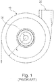
- Prior art centrifugal blower 10 includes an outlet 20, an inlet 30, an electric motor 40, an impeller 50 and a shaft 60.
- Arrows 70 indicate the general direction of airflow. Air enters the blower at the inlet 30 and is accelerated by the rotating impeller. The rotation imparted by the impeller generally directs the airflow in a tangential direction T. The volute then constrains the airflow to spiral the volute. The airflow then exits the blower in a generally tangential direction T via the outlet 20.
- blower designs are known.
- the system described for example in US20070131228 has two blowers, wherein each blower has an individual inlet, an individual airflow chamber and an individual outlet.
- a dividing wall 92 that is included in the housing of the system separates between the two airflow chambers so that they are in non-fluidic communication with one another.
- volute geometry directs the tangential spiraling airflow in a slight axial direction A prior to exiting the blower in a generally tangential direction T.
- blower The performance of a blower is often described using fan curves, which show the flow rate of air versus outlet pressure of air. Many factors affect the fan curve including impeller diameter and the number and shape of the impeller blades.
- the design process is a complex balance between competing priorities such as desired pressure, flow rate, size, reliability, manufacturability and noise. While many combinations of size, shape and configuration of components may produce a flow of pressurized air, such a result may be far from optimal, or be impractical.
- WO-A-2007/004898 relates to a breathing assistance apparatus including a manifold that is provided with or retrofittable to gas supply and humidifying devices.
- the manifold allows gases from an oxygen concentrator to be combined with the flow through a gases supply and humidifying device, most usually air.
- the combined output of oxygen and other breathing gases (air) is then humidified.
- this breathing assistance apparatus and manifold oxygen is added to the input air stream of a gases supply via an oxygen inlet port extending from the side of the manifold and its ambient air inlet aperture.
- US-A-5701883 discusses an oxygen mixing arrangement for or in a pressure support ventilator, in which a modular oxygen-providing assembly is selectively insertable into a greater respiration apparatus.
- a valving arrangement and metering for supplying the oxygen is used which is added downstream from a valving arrangement used for venting patient exhaust flow and for controlling system pressure by venting excess gas flow to the ambient atmosphere.
- WO-A-2008102216 relates to a gas supply unit for supplying pressurised gas to a patient, wherein it comprises: a pneumatic housing for supplying a flow of gas to the patient; a control housing (20) for controlling the flow of gas to be supplied to the patient; and a power supply housing (30) for supplying power to the unit (1).
- the three housings are distinct from one another and are designed for being removably coupled together to form a single unit.
- the invention relates to a patient ventilation or breathing device and components therefore for use in all forms of respiratory apparatus ventilation systems including invasive and non-invasive ventilation, positive airway pressure therapy, Continuous Positive Airway Pressure (CPAP), and particularly Bi-Level therapy and treatment for sleep disordered breathing (SDB) conditions such as Obstructive Sleep Apnea (OSA), and for various other respiratory disorders and diseases.
- CPAP Continuous Positive Airway Pressure
- SDB sleep disordered breathing
- OSA Obstructive Sleep Apnea
- the invention particularly relates to a blower for such a device.
- An aspect of the invention is directed to a blower or air pump for quietly and effectively providing a supply of air at positive pressure.
- Such blower is preferably a blower for a patient ventilation or breathing device, particularly for use in treatment of respiratory diseases or disorders as discussed in the introductory portion of the present invention as well as for use with the further aspects of the present invention.
- Such blower comprises all features of independent claim 1.
- the application further discloses a blade for use with a, preferably radial, blower for providing supply of positive pressure, and preferably with a blower according to the present invention.
- the blade is adapted to fit into an air outlet of the blower and to split the outlet into at least two, preferably parallel, channels.
- the blade preferably extends along the whole length of the outlet channel.
- the blade comprises at least two portions or sections, each having a longitudinal axis extending in the plane of the blade, wherein the two longitudinal axes are inclined vis-à-vis one another in the plane of the blade and include an angle of about 70° to 110°, preferably of about 90°.
- the blade is L-shaped.
- the blade is preferably made of the same material as (the stationary part of) the blower. Such blade preferably corresponds to the blower's blade referred to above apart from being integrally formed with a part of a blower housing.
- the blower according to the present invention is advantageous and particularly has reduced noise emission. This has been proven by comparative tests between identical blowers under identical operating conditions. At the same time, the flow and pressure of the air flow pumped by the blower is not negatively impaired by the present invention. Preferred forms and features of the blower or blade, as referred to above relate to additional improvements vis-à-vis blowers without a blade.
- the solution according to the present invention is simple, reliable, and easy to manufacture.
- the blower has one stage, in other forms the blower has more than one stage.
- the motor may be positioned in the centre and similar numbers of impellers may be positioned on either side of the motor along the axis.
- a motor is provided on the blower side axially opposite to the axially arranged inlet opening.
- the rotating portion of the blower comprises an impeller which preferably comprises a plurality of vanes extending from a disk-like shroud.
- the shroud located downwardly or away from the air inlet in the direction of air flow, preferably has a generally disk-like shape.
- the shroud preferably has a wavy or saw tooth shaped outer circumference in an axial or bottom view wherein the outer diameter of the shroud varies between a maximum outer diameter and a minimum outer diameter.
- the maximum outer diameter is reached in a vicinity of the outer tips of the vanes while the minimum outer diameter is reached between two adjacent vanes, preferably between each pair of adjacent vanes.
- the vanes extend, preferably vertically, from the shroud and are preferably formed integrally with the shroud.
- the impeller has an axis of rotation and is preferably of general rotational symmetry with regard to said axis.
- the vanes are radially arranged and extend from an inner diameter to an outer diameter.
- the vanes have a substantially uniform height from their starting point at their inner diameter close to the impeller's axis of rotation until a first intermediate diameter; and a decreasing height from said first intermediate diameter towards their end at an outer diameter, the first intermediate diameter lying between the inner and outer diameters.
- the blades are substantially straight from their starting point at their inner diameter close to the impeller's axis of rotation until a second intermediate diameter; and are curved from said second intermediate diameter towards their end at the outer diameter, the second intermediate diameter lying between the inner and outer diameters.
- the second intermediate diameter preferably lies between the first intermediate diameter and the outer diameter.
- the second intermediate diameter preferably lies between the inner diameter and the first intermediate diameter or equals the first intermediate diameter.
- the curvature can be either positive or negative while it is preferably that the curvature is negative, i.e., away from the direction of rotation.
- the geometry of the increase in height is preferably aligned with the geometry of the housing or stationary part and preferably corresponds thereto.
- the impeller preferably has an inertia or moment of inertia of below about 3,2 g cm 2 and preferably of below about 2,5 g cm 2 .
- the moment of inertia lies in a range between about 1,2 and 3,2 g cm 2 and preferably between about 1,2 and 2,5 g cm 2 and preferably is about 2,2 g cm 2 .
- the impeller is preferably made of plastic, preferably O 2 resistant plastic and/or preferably unfilled plastic material.
- the impeller is advantageous and particularly has reduced noise emission, a large pressure delivery for a given motor speed, allows supply of a given pressure at a relatively low motor speed, and has a fast response time. Furthermore, the impeller preferably provides a rigid impeller with comparatively low inertia. The impeller is particularly suitable for high-speed rotation, e.g. of about 50k r/min. The impeller is particularly quiet, high efficient, allows fast motor acceleration to respond to the patient needs and exhibits very low stress at high speed. This particularly enables it to cycle between high and low speeds for ventilation and VPAP / BiPAP with very low risk of fatigue failure due to low alternating stress level.
- the application further discloses a gasket and an air path for use in ventilation or breathing devices as referred to above and particularly for use with a blower of the present invention.
- the gasket is, i.a., adapted to sealingly separate a high pressure area of a ventilation and breathing device from a low or ambient pressure area.
- the gasket preferably furthermore allows an advantageous arrangement of different areas and/or components of a blower and particularly of the blower, the flow path and/or muffling chamber(s).
- the gasket preferably has a core of a comparatively hard material, when compared to an outer material of the gasket, and preferably a core being made of aluminium.
- Said core is provided with one or more structural elements, particularly for allowing air to be pumped from a low pressure area to a high pressure area by means of, e.g., a blower, according to the present invention.
- the gasket is furthermore preferably provided with structural elements which are suitable for providing a suspension to a blower, for sealingly connecting the gasket to a first and/or second part of a housing defining an air path.
- Said gasket is provided with a skin or coating of elastic plastic material.
- Said material is comparatively softer than the core of the gasket and preferably is silicone. Silicone is particularly preferred since it enhances O 2 resistance, is biocompatible and has advanced dampening and sealing characteristics.
- substantially the entire core of the gasket is provided or coated with such skin.
- substantially' is understood to mean more than 80% and preferably more than 90% and further preferred more than 95% and up to 100% of the core's surface area.
- certain portions of the core may remain uncoated. This is particularly the case if the core is held or supported by support means during coating so that no coating or skin will be applied at the contact portions between support member and core.
- Such gasket is preferably advantageous in that it allows a sealing separation of a high pressure and low pressure area and defining at least two compartments in the ventilation and breathing device.
- the gasket is adapted to sealingly contact a first part of a housing which is provided with two chambers being open to one side of said first housing part wherein both chambers open towards the same side of the first housing part.
- One of said chambers defines a high pressure area and the second chamber defines a low pressure area, the first part of the housing and thus each chamber of the housing sealingly contacting one side of the gasket.
- the gasket of the present invention provides support and suspension for a blower to be mounted to the gasket.
- the gasket inherently provides parts, preferably substantial parts of the required fastening, supporting and dampening means for such blower.
- the blower, and its motor can be mounted to the gasket on one side thereof wherein the core of a relatively hard material provides a supporting structure while the elastic plastic skin of the gasket is adapted to provide connection and support means which particularly allow a sealed and dampened connection between gasket and blower.
- the blower and motor is advantageously positioned so that air can be sucked in or ventilated from the low pressure chamber through the gasket into the blower and then, at elevated pressure, to the high pressure area.
- the high pressure area or chamber and the low pressure area or chamber are provided next to one another in a first part of a housing and are both sealingly closed at one of their sides by means of the gasket.
- the gasket preferably has flat or substantially planar extensions while it is understood that the gasket is not exactly planar but provided with various structural elements, such as lips, rims, flanges, or elevations, for sealing connection with one or more parts of a housing, for positioning said housing and/or for supporting, dampening and positioning of parts attached to the gasket, e.g., the blower.
- the gasket is adapted to sealingly close two housing parts, preferably each located at one side of the gasket.
- the first part of the housing preferably defines or is separated into a high pressure compartment and a low pressure compartment.
- the second part of the housing preferably also comprises two chambers or compartments one of which houses and supports the blower while the second one provides a path for the pressurised air be lead from the high pressure chamber defined in the first part of the housing through the gasket and towards the outlet of the device, e.g., into a hose directing the pressurized air to a patient.
- the first and second chambers defined by the first part of the housing and the gasket are preferably filled with a dampening or muffling material and are preferably foam filled and even more preferably silicone foam filled.
- the air path is thus preferably defined by the gasket and at least one part of a housing, preferably two parts, being in sealing contact with the gasket.
- the gasket preferably comprises three, and preferably at least three, openings to allow air to flow from one side of the gasket to the other.
- the skin of the gasket provides combined sealing and connection means, particularly for sealingly supporting and dampening the blower.
- the sealing and connection means is preferably adapted as an opening rim, preferably ring-shaped, into or through which a part of the blower, preferably the inlet and/or outlet channel, can be pushed.
- the rim then sealingly connects to the blower.
- the rim is supported on or to the core of the gasket by means of a suspension and/or dampening structure, such as a bellow, which is also formed by the skin or coating. While it is understood that the provision of one gasket with one planar core is preferred, there may alternatively be provided e.g. two or more separate cores and/or core(s) which may extend in different planes.
- the gasket provides various combined and improved functionalities such as support of the housing parts and/or the blower, dampening of the housing parts and/or the blower, sealing different parts of the housings, such as the different pressure areas, and muffling.
- the gasket preferably is, particularly due to the silicone skin and its structural arrangement, of increased O 2 safety, being non-aging and allowing improved connection of, e.g., the housing and the blower as well as positioning thereof.
- the gasket significantly improves the design, size and arrangement of the air path and its components and supports and improves the ease and quality of assembly.
- the gasket allows a separation of the air path from other parts of the ventilation or breathing device, such as from the electronics, thereby increasing hygiene and safety.
- the gasket allows the provision of a separable and exchangeable air path, particularly of a small air path including few components and allowing an improved air flow with good noise reduction.
- the gasket thus allows an arrangement in which a, preferably sensorless, blower unit is arranged outside the air path, improving hygene and safety and additionally leading to a reduction of costs, parts, required space etc.
- the application further discloses a cable to be used in ventilation or breathing devices as referred to above and particularly for use with a blower of the present invention.
- the improved, preferably self-sealing, cable comprises a silicone coating.
- a silicone coating Preferably, there are provided two or more, preferably four or more, and even more preferred six or more metal wires, preferably stranded wires or litz wires. These metal wires are located next to one another, preferably generally in one plane or in a circular or oval arrangement while being distanced from one another. These wires are provided with one silicone coating which is directly applied to the wire, i.e., with no intermediate sheath or the like between the wire and the silicone coating.
- the self-sealing cable is of particular advantage in that it provides electronic insulation of the different metal wires vis-à-vis one another and the surrounding, exhibits an improved O 2 safety and can be clamped between two parts in a self-sealing manner.
- the self-sealing cable can extend through the contact region between, e.g., two housing parts connected to one another and can extend from an inner side of such housing to an outer side thereof in a sealed manner without the need for anv additional sealing material and the like.
- the self-sealing cable is in sealing contact with the parts, here the parts of a housing, between which it extends without the need of any particular additional sealing means or the like.
- the silicone coating preferably has a certain minimum thickness, e.g., of at least 0,5mm measured along the shortest distance from the outer circumference or surface of the cable to one of the wires.
- Such cable is preferably adapted for use with a blower and preferably with the blower according to the present invention and allows power supply, control and the like of said blower.
- the self-sealing cable is used in combination with the gasket desribed above and preferably also the blower according to the present invention so that the blower can be located in the air path while the cable extends from the motor inside the air path to the outside of this air path in a self-sealing manner, thereby increasing the freedom of construction, ease of manufacture and assembly and the like.
- certain dimensions of contact regions for leading the self-sealing cable in a sealing manner through the contact region of two contacting parts may be of further advantage.
- a predefined gap between the two parts is provided with the general shape of and slightly smaller dimensions than the cable.
- the application further discloses an inlet member including an inlet filter for ventilation or breathing devices as referred to above and particularly for use with a blower of the present invention.
- the inlet member forms part of the air path as described above.
- Such inlet member preferably comprises an inlet housing comprising at least a first part and a second part.
- the housing additionally comprises a third part.
- the inlet member housing comprises an air inlet, preferably provided in and/or between two of the first part and/or the second part of the housing as well as an air outlet, preferably comprised in the second and/or third part of the housing.
- the inlet member further comprises an inlet or filter path extending from the air inlet to the air outlet.
- the filter path constitutes part of the air path of a ventilation or breathing device and/or the air outlet of the filter is adapted to release filtered air into a ventilation or breathing device and its air path, respectively.
- the inlet member comprises an inlet filter for filtering the air flowing along the inlet path.
- the inlet member and the inlet filter, respectively, are preferably located at the low pressure side of a ventilation or breathing device.
- the air inlet allows ambient air to enter the inlet member and the filter and is not limited to one individual opening. Rather, the air inlet may comprise a plurality of separate openings to the ambience such as slots and/or holes.
- the inlet member comprises, in addition to the air inlet, an additional or second inlet, e.g., for the provision of oxygen.
- second inlet is preferably provided in or by the second part of the inlet housing and is accessible from the outside via a corresponding opening or cut out provided in the first part of the inlet housing.
- the second inlet is provided as a separate part, connectable to one of the inlet housing parts, preferably the second inlet housing part, which separate part preferably extends to the second outlet to be described in more detail below.
- the filter element is preferably arranged inside the inlet housing and more preferred between the air inlet and the air outlet of the filter. Alternatively, the filter element may also constitute or cover the air inlet.
- the filter element extends along the whole cross section of the air inlet path such that all air flowing through the air inlet member flows through the filter element.
- Said filter element comprises a frame as well as a filter material connected to the frame.
- the filter frame is preferably partly overmoulded with a soft material, of e.g. about 70 Shore A, for improving handling and enhancing sealing of the filter frame in the inlet filter path.
- the filter frame is provided with a sealing lip.
- the filter element and thus its frame and filter material preferably generally extend in one or at least one plane.
- the filter frame is preferably biased.
- the filter element has a slight radius resulting in a tension when assembled in a substantially plane position, thereby improving the proper sealing of the filter element in the inlet flow path.
- the filter element comprises a cut-out, recess or opening, particular for allowing the extension of the additional or second inlet or the corresponding second inlet path past the filter element, without the gas or oxygen provided via the second inlet having to flow through the filter.
- the second or oxygen inlet path which preferably has a channel like configuration, extends from the second or oxygen inlet, preferably forming part of the second part of the inlet housing or being a separate part attached thereto, along the filter element to the outlet provided in or at the second part of the housing.
- the oxygen inlet path is thus preferably part of the second part of the inlet housing.
- the inlet path protrudes from the second part of the inlet housing and extends up to or through the first part of the inlet housing.
- the first part of the inlet housing is provided with an opening or recess for allowing or facilitating accessibility of the oxygen inlet.
- the oxygen inlet is preferably provided with a connection means for connecting an oxygen supply.
- the second part of the inlet housing comprises at least one outlet, preferably at least a first outlet and a second outlet.
- the first outlet is in fluid connection with the first (air) inlet and thus the inlet air flow.
- the second outlet is in fluid communication with the second (e.g. oxygen) inlet and thus the oxygen flow.
- the first and second outlets are coaxially arranged.
- the second outlet has a circular cross section while the first outlet has a ring shaped cross-section or geometry.
- the second or oxygen outlet is set back with regard to the first or air outlet.
- the second outlet is located upstream of the first outlet seen in the direction of air/oxygen flow, preferably immediately, i.e., less than 5mm, upstream.
- the first and second outlet are preferably provided in the second part of the housing.
- the air outlet and the oxygen outlet are preferably arranged such that an air flow through the air inlet and through the filter is mixed with the oxygen supplied through the second or oxygen inlet, preferably due to the arrangement of the air and oxygen outlets as referred to above.
- the air outlet and, if provided, also the oxygen outlet preferably lead to or open into an inlet chamber provided by, behind, and/or in the second part of the housing.
- Such inlet chamber preferably constitutes an inlet muffling chamber and/or a fluid flow path and/or a mixing chamber for properly mixing the air flow with the oxygen flow.
- such muffling chamber is defined and/or closed by a third inlet housing part.
- the inlet member is of particular advantage and allows the filtering of the air as well as the mixture of air and oxygen close to the air inlet and at the low pressure side of a ventilation or breathing device. Therefore, the provision of specifically pressurized oxygen or an individual adaption of the oxygen pressure to the breathing pressure becomes obsolete. Both, air and oxygen, preferably in a mixed form, can thus be supplied to the patient at optimized therapy pressure.
- the inlet member of the breathing device functions as a muffler thus decoupling and dampening the noise emitted from the breathing device and the blower towards the inlet side.
- the inlet member according to the present invention additionally exhibits advantageous sound dampening properties and particularly reduces the overall noise of a ventilation or breathing device.
- the housing of the inlet member preferably comprises structural elements for connection and securing the inlet member to a or inside a breathing or ventilation device.
- the first inlet housing part particularly serves the purpose of protecting the inlet filter or the filter element from damages, for dampening noise, for securing the filter, and/or for aligning the visible exterior design of the inlet member with the ventilation device housing and appearance of a ventilation device to which the inlet member is to be connected.
- the inlet member particularly allows an easy and safe inlet member handling.
- the filter element can be easyly handled and replaced, e.g., by the patient, a nurse or a service team member and is easy to ship and store.
- the inlet member furthermore reduces and preferably avoids bypass flow and serves a pre-muffler/silencer while allowing an optimized pressure decoupling between the delivery pressure to the patient and the oxygen supplied pressure.
- the inlet filter preferably seals the air inlet path so that all incoming air is filtered.
- the inlet filter is a dust and/or pollen filter.
- the application further discloses a modular ventilation or breathing device as referred to above and particularly for use with a blower according to the present invention.
- the respiration or ventilation device is preferably of an advantageous modular structure and comprises a housing module, preferably provided with operator input and display means. Additionally, there is provided an electric module, preferably comprising a skeleton carrier for carrying, i.a., a control unit and further electronics required, and for providing structural support as well as for allowing defined positioning of the modules and parts of the ventilation device.
- the ventilation device further comprises an air path module comprising an air path housing, comprising an air path inlet and an air path outlet, in which a blower is located.
- the air path housing comprises two parts each of which is sealingly connected to one side of the gasket described above while the gasket and/or the air path housing carries a blower including a motor, preferably the blower according to the present invention.
- the air path module includes an inlet member and/or a patient connector.
- the electric module is preferably further adapted to be connected to and support the housing of the ventilation device as well as to support and/or position the air path module.
- the skeleton carrier and/or the electric module is preferably adapted for and comprises means for allowing a proper alignment and positioning of the different parts and modules of the ventilation device such as the parts of the housing module and/or the air path element.
- the electric module preferably comprises the power supply, battery or accumulator pack, control unit and/or a display unit.
- the blower and its motor is/are simply plugged or laid into the air path housing with out the need for any screws or additional fastening members. Rather, the necessary suspension elements are provided integrally with air path module and the housing module. All that needs to be provided are silicone cushions for dampening the blower and motor in the housing.
- the device is adapted such that the electric module is simply laid onto the air path element without the use of further screws or other additional fastening means.
- the inlet member and/or a patient connector is connected to the air path element, such as by plugging one into the other, preferably via a plug-in connector and/or flow sensor connector, and the air path is laid into the lower part of the housing module, and the electric module is placed over it, the combined electric module, the air path module including the inlet member, which are connected to one another without the use of screws or additional separate fastening means, the upper part of the housing is placed over them. Then the, preferably two, parts of the housing module are screwed to one another, thereby simultaneously fixing and securing the position of the different modules (air path module, electric module and housing module).
- This configuration particularly allows an easy and advantageous way of manufacturing of the ventilation device as well as of its assembly.
- a reduced number of parts can be provided which are individually manufactured, prepared and mounted. These modules can then be easily assembled to constitute the ventilation device.
- the device is therefore of particular advantage since it allows an easy and fast assembly as well as disassembly and thus an improved maintenance or repair. Individual components can be easily replaced. Particularly all components being in contact with air inhaled or exhaled by a patient can be easily replaced.
- the modular ventilation device is also of particular advantage from the point of cleanliness and/or security.
- the device allows a clear separation between air path, including eventual oxygen supply, and electronics and/or housing. No part of the device housing constitutes part of the flow path. Not part of the electric or electronics and thus no circuit board or electric part lies in the air path.
- the only sensor to be provided in the air path is the flow sensor which is preferably located between inlet member and flow path housing.
- the flow sensor which is preferably located between inlet member and flow path housing.
- no dust and/or lint is lead to the electronics together with the air flow.
- the patient is not exposed to the danger of inhaling smoke of burning of electronic parts.
- Disclosed is also a method for supplying air at positive pressure to a patient for treatment including providing air to a blower of the invention, pressurizing said air and supplying the air at positive pressure to a patient.
- said method is used for providing a therapy as discussed in the introductory part of the application, such as a Bi-PAP therapy.
- a therapy as discussed in the introductory part of the application, such as a Bi-PAP therapy.
- Disclosed is also the use of one or more of the aspects of the invention in the application of such method or therapy.
- the ventilation device is of particular advantage, as becomes clear from the overall discussion of advantages and benefits of the invention.
- an effective and efficient ventilation device which allows the provision of an optimized, fast therapy at reduced power consumption.
- the device can suitably be used with a battery pack - instead of being dependent on the generally power supply.
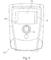
- Figs. 3, 4 and 5 show a three-dimensional front, back and top view of a ventilation device.
- the ventilation device 100 comprises a housing 104 provided with various input means 106 such as turn buttons, push buttons, and the like as well as a display or window unit 108 for displaying information, such as settings etc., to the user.
- the ventilation device further comprises one or more air inlet openings, generally referred to as inlet 110, and an air outlet 112, preferably provided with means of for connecting further components of a breathing or ventilation system such a respiratory tube or hose for delivering pressurized air to a patient and/or a humidifier.
- the ventilation means 100 furthermore comprises a filter, preferably provided by an inlet member, provided behind the air inlet 110 for filtering ambient air entering the air inlet 110 of the ventilation device 100 and then being directed though the filter.
- the ventilation means preferably comprises an oxygen inlet 118 as well as means for connecting a supply of oxygen and for allowing, e.g., additional oxygen to enter the ventilation device 100.
- oxygen is, preferably in an inlet member and thus inside the ventilation device 100, added to the incoming air sucked in via the inlet 110 and through the filter and preferably mixed therewith.
- the filter, and preferably also the inlet member is an integral part of ventilation device 100, preferably its air path.
- Housing 104 of ventilation device 100 comprises, an upper housing part 104a and the lower housing part 104b.
- the ventilation device 100 may further comprise additional ports or connection means 120 which allow connection of cables, such as power cables, USB cables, sensor cables and the like, i.e., constituting interfaces for connection of further devices for exchanging information and for providing power input.
- a ventilation device 100 may comprise means for receiving a battery pack for providing the necessary power for mobile operation of the ventilation device.
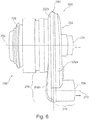
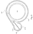
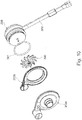
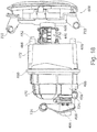
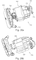
- Figs. 6 to 9 show various three-dimensional views of a preferred blower according to the present invention or of parts and components thereof.
- Fig. 10 shows an exploded view of the blower shown in Figs. 6 to 9 .
- Blower 200 comprises a housing 202 having the general shape of a volute.
- the housing comprises two parts 202a, 202b, which are connected, e.g., mechanically and/or by means of ultrasonic welding.
- the housing 202 constitutes the stationary portion of the blower 200.
- the blower 200 further comprises a rotating portion comprising at least one impeller and a shaft to be driven by electric motor 208.
- the electric motor 208 may be a brushless d.c. motor.
- the blower has one stage while it is well understood that the blower may comprise two or more stages.
- the rotating portion of blower 200 is not shown in Figs. 6 to 9 .
- impeller 300 constitutes the rotating portion of blower 200 according to the present invention.
- the blower comprises an air inlet 204, preferably having a tubular shape, as well as an air outlet 206.
- Air inlet 204 is axially arranged, i.e., so that air enters the blower at the inlet 204 in a generally axial direction A (compare Fig. 2 ).
- the term axial used herein with regard to the blower relates to the longitudinal axis of the stationary portion, e.g., around which the volute winds, and/or around which rotating portion rotates. That axis is shown in Fig. 6 as axis 250. Arrows indicate the general direction of air flow.
- the rotation imparted by the impeller generally directs the air flow radially outwardly in a tangential direction T (compare Fig. 1 ) wherein the volute then constrains the air flow to spiral the volute.
- the air flow then exits as the blower or volute in a generally tangential direction T via the outlet 206.
- the volute geometry directs the tangential spiralling air flow in a slight axial direction prior to exiting the blower in a generally tangential direction.
- outlet 206 comprises a first axis 260 being generally tangentially arranged with regard to the blower and particularly its volute shape and/or rotation of impeller.
- Tangential axis 260 is preferably arranged essentially perpendicular to axial axis 250.
- axis 250 and tangential axis 260 are distanced (shortest way) by less than 50mm, and preferably by a length which generally corresponds to the radius of the blower, volute, and/or impeller.
- axis 260 preferably is a tangent to a radius 232 around the axis of rotation of the rotating part of the blower.
- the outlet channel 206 of the blower 200 is, as shown, preferably L-shaped and comprises a first outlet portion or first outlet channel 216 extending along tangential axis 260 and a second outlet portion 218 extending in general perpendicular thereto and preferably parallel to axial axis 250.
- the outlet channel is not L-shaped but may be curved.
- axis 270 The axis of the second portion 218 of the outlet is herein referred to as axis 270 and is preferably parallel to axial axis 250. However, it will be well understood that axis 270 of the second outlet portion 218 may have different directionalities. According to a preferred embodiment, axis 260 and 270 include an angle of preferably about 70° to 110° and preferably of about 90°.
- the length of the first portion 216 of the outlet lies in the range from about 12 to 23 mm and preferably of about 18 mm along axis 260.
- the length of the first portion 216 along axis 260 starts from the intersection of axis 260 with the outer radius of the blower, as is indicated in Fig. 8 .
- the outer radius of the inside of blower 200 is indicated as 230, while the starting point of the first portion 216 is indicated as 'p'.
- First portion 216 preferably ends at the cross-section of the axis 260 of the first portion of the outlet 216 and the axis 270 of the second portion of the outlet 218.
- the blower is made of plastic material.
- the diameter of the outlet 206 is about 12 to 23 mm and preferably about 17mm
- the diameter of the inlet 204 is about 10 to 20 and preferably about 15 mm
- the radius of the blower is about 57 to 67 and preferably about 62mm
- the shortest distance between axis 250 and 270 is about 37 to 47mm and preferably about 42mm.
- the inlet 204 of the blower is of generally tubular shape and extends from the blower housing 202a.
- Inlet 204 preferably has a length of about 5 to 15mm, preferably of about 10mm.
- inlet opening 204 and outlet opening 206 lie in one plane.
- the air outlet 206 is split into at least two channels 212, 214, which are preferably parallel.
- the air outlet 206 is of substantially radial cross-sectional shape wherein the outlet is split such that each of the two channels 212, 214 has a semi-circular cross-section and particularly has a substantially identical cross section.
- the two channels preferably extend along the length of the outlet 206 and preferably along first portion 216 and/or second portion 218, preferably along both portions.
- Blade 210 is preferably made of the same material as the blower and is preferably integrally formed with one of the two housing parts 202a or 202b of the blower housing or volute 202. Alternatively a portion of the blade 210 may be integrally formed in each of the two housing parts 202a and 202b. However, it will be well understood that blade 210 may also be provided separately and to then be connected to one or two of housing or volute parts 202a, 202b.
- Blade 210 preferably extends substantially along the length of outlet 206, and preferably along the length of the first part 216 and the second part 218 of outlet 206. Blade 210 splits outlet 206 into two channels, namely a first channel 212 and a second channel 214 both of which individually extend along outlet 206 and first and second outlet portion 216, 218. Thus, blade 210 preferably comprises a first portion 220 and a second portion 222 corresponding to the first and second part 216, 218 of outlet 206.
- Blade 210 preferably extends parallel to the direction of the air flow through the outlet and/or to the longitudinal axis 260 or axes 260, 270 of the air outlet 206. Blade 210 preferably extends in a plane defined by two axes, one being generally parallel and one being generally perpendicular to the axis of the volute.
- Blade 210 is preferably located and arranged such that it extends in or into the outlet channel from a starting point 'p' as defined above. Preferably, blade 210 starts at said starting point 'p' or distanced from that starting point, preferably by about ⁇ 3mm. As will be understood, if blade 210 extends to far into the volute, blade pass noise will be increased. If blade 210 starts to far from the volute, efficiency will be less.
- outlet 206 has a substantially circular cross-section while blade 210 splits outlet 206 along its diameter into the first and second channel 212, 214, which may be of equal shape and cross-sectional diameter, preferably of semi-circular cross-section.
- Blade 210 is preferably substantially planar and extends along the axis of outlet flow 260 and/or 270 depending on the design of outlet 206. Therefore, in line with outlet 206, blade 210 comprises a first part 220 and a second part 222 which extend along longitudinal axes preferably being identical to axis 260, 270 of outlet 206. Preferably, blade 210 is substantially L-shaped.
- the blade has a thickness of about 0,5 to 1,5 mm, preferably about 0,8 to 1mm, a width of about 10 to 20mm, preferably 13 to 17 mm (depending on the size of the outlet channel), and a length of about 20 to 30mm, preferably of about 23 to 27 mm.
- the length of the blade is preferably at least about 5 to 10mm and it preferably extends along the entire length of the outlet channel.
- the thickness of the blade may vary, e.g. for allowing improved demoulding after being injection moulded.
- blade 210 is integrally formed with blade housing part 202a by means of injection moulding.
- Blade housing part 202b comprised a recess 226 for receiving blade 210.
- Blade housing part 202b preferably comprises an opening 240 (see Fig. 9 ) for receiving a rotating member, e.g. impeller 300. In use (compare Fig. 6 ) opening 240 is closed by motor 208.
- a blade generally corresponding to blade 210 is alternatively or also provided in a blower inlet 204 for splitting the inlet channel 204, which preferably extends along axial axis 250, into two, preferably parallel inlet channels.
- FIG. 10 shows an exploded three dimensional view of blower 200 and motor 208.
- blower housing parts 200a and 200b including blade 210 can be individually assembled wherein a rotating portion, e.g., impeller 300, is attached to drive axis of motor 208 and inserted into blower 200 via opening 240 provided in housing part 202b.
- Said opening 240 is preferably closed and sealed by the front face of motor 208, preferably using a sealing member 241.
- Motor 208 preferably comprises a cable 500 to be discussed below.
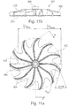
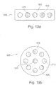
- Impeller 300 is preferably made of one-piece moulded, preferably injection moulded, plastic construction; although other suitable materials or manufacturing techniques could be employed.
- the impeller 300 comprises a plurality of vanes 302 extending from a disk-like shroud 304.
- Shroud 304 is, vis-à-vis the vanes 302, located further distanced from the air inlet or downstream when seen in the direction of the air flow. Vanes 302 extend from shroud 304 into an upstream direction.
- Shroud 304 preferably incorporates a hub or bushing 306 that is adapted to receive a motor shaft 224.
- Shroud 304 is preferably of a disk-like shape having a maximum outer diameter of about 38 to 46 mm, preferably of about 42mm.
- the radially outer tips of the vanes 302 preferably extend to the outer diameter of shroud 304.
- the outer diameter of shroud 304 has a wavy or saw tooth shape and varies between a minimum outer diameter Dmin and a maximum outer diameter Dmax.
- the maximum outer diameter Dmax is provided adjacent the radially outside tips of the vanes 302 while the minimum outer diameter Dmin is provided between each of two neighbouring vanes or tips of vanes 302.
- the maximum outer diameter Dmax lies in the range of about 38 to 46 mm and preferably about 42 mm and/or the minimum outer diameter lies in the range of about 24 to 32 mm and preferably about 28 mm.
- the difference between the maximum and minimum outer diameter is in the range of about 4 to 22 mm and preferably or about 10 to 18 mm.
- vanes 302 are curved in radial direction and are preferably tapered in height in their radially outer portions.
- the reduced height at the tips of the vanes preferably reduces turbulences and/or noise as well as the inertia of the impeller 300.
- vanes 302 have an inlet height, i.e. at their inner diameter with regard to impeller's 300 axis where the air flow enters the impeller which uniformly extends along a first portion of the vanes 302 towards their (radially) outer end or tip.
- the height of the vanes 302 is reduced from a first height to a second height, being lower than the first height, wherein the second height constitutes the outlet height at the radially outer end of the vanes 302.
- the first part extends from a starting point at the vanes' inner diameter close to the impeller's axis of rotation until a first intermediate diameter Dint1.
- the reduction in height starts from the first intermediate diameter towards their end at an outer diameter.
- the first intermediate diameter lies between the inner and outer diameters.
- the maximum height of a blade is about 4 to 6 mm and is preferably about 5 mm and/or the minimum height of a blade, preferably close to its tip at its outer diameter, is about 1,5 to 3,5 mm, preferably about 2,8 mm.
- the geometry of the increase/decrease in height is preferably aligned with the geometry of the housing or stationary part and preferably corresponds thereto.
- the difference between the inlet height and the outlet height, additionally or alternatively to the above preferred height dimensions, of the vanes 302 lies in the range of about 2,5 to 4,5 mm and more preferred of about 2 to 2,5mm.
- the height reduction is preferably linear and/or curved.
- the blades are substantially straight from their starting point at their inner diameter close to the impeller's axis of rotation until a second intermediate diameter Dint2; and are curved from said second intermediate diameter Dint2 towards their end at the outer diameter, the second intermediate diameter lying between the inner and outer diameter.
- the second intermediate diameter Dint2 lies between the first intermediate diameter Dint1 and the outer diameter Dmax.
- the second intermediate diameter Dint2 may also lay between the inner diameter and the first intermediate diameter Dint1 or equal the first intermediate diameter Dint1.
- the curvature can be either positive or negative while it is preferably that the curvature is negative, i.e., against direction of rotation.
- the positive orientation of the curvature achieves an advantageous relation of pressure over flow, thus allowing a continuous and fast reaction of the blower/impeller on changes in flow.
- the first intermediate diameter Dint1 is preferably about 20 to 24mm and preferably about 22mm and/or the second intermediate diameter Dint2 is preferably about 21 to 25 mm and preferably about 22 to 24 mm.
- the vanes 302 have an inclination with respect to an associated tangent at their tip of between 0° and 60°, e.g., about 40° (see Fig. 11a ).
- impeller 300 has 4 to 100 blades 302, e.g., 11, while the number is preferably uneven.
- the impeller preferably has an inertia of less than about 3,2 g cm 2 , preferably less than about 2,5 g cm 2 and more preferred of about and/or less than 2,2 g cm 2 .
- the inertia lies in a range between about 1,2 g cm 2 , preferably 1,7 g cm 2 and the above upper values.
- the impeller is preferably made of plastic, preferably O 2 resistant plastic and/or preferably unfilled plastic material, such as a thermoplastic material.
- the geometry and the design of the impeller 300 particularly allows a significant noise reduction vis-à-vis impellors known in the art and additionally provides a comparatively low inertia. In addition, the effectiveness of impelling or pumping air is significantly reduced. It will be understood that the measures and dimensions referred to above are preferred and can be varied by up scaling or downscaling the size of the impeller. It is preferred that the impeller is used in combination with the blower of the invention.
- Fig.13 shows the core 402 of a gasket 400.
- Fig. 13a shows a view on the gasket core 402 from a first side and
- Fig. 13b show a view of said gasket core from the opposite side.
- Fig. 13c shows a view of the core 502 of said gasket 500 from a third side (perpendicular to the views of Fig. 13a and 13b ).
- areas 406 These areas, which result from the support of the core 402 during the coating process are indicated as areas 406. It will be understood by the person skilled in the art that, depending on the coating or manufacturing process, different areas than those shown in Fig. 14 can remain uncoated. For example, areas 406 can be larger or smaller or there can be more or less or even none of such areas.
- a gasket 400 comprises at least three holes or openings for defining an air path from a first side of gasket 400 to a second side of gasket 400 and/or visa-versa.
- gasket 400 comprises a first hole 408 for allowing air to be sucked in from an air inlet at a low pressure area located on the second side of the gasket 400 into a blower located on the first side of the gasket.
- An opening or hole 410 is provided for establishing a passage of pressurized air supplied by a blower to flow from the first side 450 of the gasket (as shown in Fig. 14a ) to a second side 452 of the gasket (shown in Fig.14b ).
- a third opening 412 is provided for allowing air to flow from a second side of the gasket (as shown in Fig. 14b ) in a still pressurized state to the first side of the gasket (shown in Fig. 14a ).
- gasket 400 is provided with additional structural elements for allowing proper positioning, sealing connection, dampening and/or supporting of parts attached to the basket or between the gasket and parts attached thereto.
- Such elements can be lips, rims, flanges, elevations, recesses or the like which can either be provided in the core 402 of the gasket and/or in the gasket's coating 404.
- respective structural elements are provided as part of coating 404.
- rims 420, 422, 424 and 426 are provided as part of coating 404.
- these rims 420-426 allow proper alignment, additional support and/or improved sealing of elements contacting gasket 400.
- rim 420 cooperates with a blower attached to the first side of gasket 400 while rims 422 and 424 and 426 are adapted to co-operate with channels or chambers of a housing or parts of a housing attached to the gasket 400.
- co-operation includes mechanical and/or visual co-operation, the latter particularly allowing improved assembly.
- support structures 428 and 430 which are associated with the first and second holes, respectively.
- These structures 428, 430 are preferably adapted as structures defining a hole or opening being aligned with the first hole 408 and the second hole 410 as referred to above. In the following it will thus only be referred to the first and second hole 408, 410 for the ease of reference.
- Support structures 428 and 430 which can be also referred to as the first support structure 428 and the second support structure 430 are preferably substantially circular but may take other geometries.
- the opening 408, 410 provided by said first and second support structure 428, 430, respectively, is preferably defined by an inner circumference of said support structures 428, 430.
- support structures 428 and 430 provide a system for sealing connection and dampening of as well as for positioning a blower to be connected with the gasket 400, preferably a blower 200 according to the present invention.
- the inlet channel 204 of such blower then extends through first opening 408 while the outlet channel 206 extends through outlet 410.
- Gasket 400 is, on its first side 450 on which the blower is preferably located, preferably provided with additional positioning and support means 432 here adapted to be circular protrusions 432 protruding from the first side of coated core 400.
- Fig. 15 shows core 400 in combination with a blower 200 including motor 208, preferably a blower in accordance with the present invention, and with fluid flow path members 460 and 462.
- Fig. 15a shows a view generally corresponding to the one of Fig. 14c while the blower 200 is shown in a view corresponding to that of Fig. 6 .
- blower 200 is attached to the first side 450 of gasket 400 with its inlet channel 204 extending through opening 408 and its outlet channel 206 extending through opening 410.
- the blower 200 is supported by support member 430 and additionally rests on or contacts support members 432.
- Flow channel member 460 constitutes and defines a first flow channel 460a.
- Flow channel member 460 is located on a low pressure side of blower 200 and fills a low pressure chamber (to be discussed below) and constitutes a flow channel 460a.
- Flow channel member 460 is also referred to as low pressure flow channel member 460 and is preferably made of a foamed material, preferably a silicone foam and preferably of a closed-cell silicone foam.
- Flow channel member 462 defines a flow channel 462 located on a high pressure side of gasket 400 and preferably fills a high pressure chamber (to be discussed below).
- high pressure flow channel member 462 defines a first flow channel 462a and a second flow channel 462b through which pressurized air flows in opposite directions.
- Flow channels 462a and 462b may be established as one channel making a, e.g., 180°, turn, or may be established as, e.g., two, individual flow channels being directed in opposite or different directions while the turn or connection between these channels is established by a flow directing means, e.g., part of a housing.
- flow path 460a as preferably defined by flow channel member 460 extends from a connecting member 440 to through gasket 400 into blower 200.
- Connector 440 preferably comprises a sensor 442, preferably a flow sensor, provided on or attached to a dampening and connecting member 446.
- Connector 440 is preferably connected to housing 472 (see Fig. 16 ) to establish fluid connection with flow path 460a and is further adapted to be connected to inlet member 600 (see, e.g., Fig. 18 ) to establish fluid connection with the inlet flow path.
- Connecting member 446 is preferably made of elastic material and/or arranged to be connected to flow path housing 472 and/or inlet member 600 by means of a plug-in connection. Due to its elastic properties, connecting member 446 preferably also functions as a dampening member.
- sensing means 448 of sensor 442 can be seen as well as flow channel parts 462a and 462b. Through flow channel part 462a outlet 206 and blade 210 of blower 200 are visible.
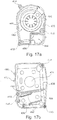
- the second flow path housing part 472 comprises an inlet 474 being in fluid communication with the first fluid flow path 460a, opening 408 and inlet channel 204 of blower 200, whereas the second housing part 470 comprises an outlet opening or channel 476 being in fluid communication with fluid flow path 462 (462a, 462b), openings 410 and 412 as well as with the outlet opening or channel 206 of blower 200.
- a support and/or noise shield 478 supports and/or shields noise emitted from an inlet connector 440 (only connecting member 446 forming part of connector 440 shown in Fig. 16a ) for connecting second flow path housing part 472 with an air inlet member 600.
- Such connector 440 preferably comprises a flow sensor 442 for sensing the flow of the air or air and oxygen entering the flow path housing.
- an outlet connector 458 (not shown in Fig. 16 ), preferably a silicone bellow connector or decoupler, for connecting the flow path housing to a patient connector 456 (not shown in Fig. 16 ).
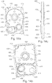
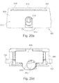
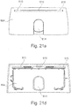
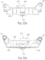
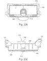
- Figs. 17a and 17b show views into the first and second part of housing 470, 472, respectively.
- Fig. 17a shows a view along line A-A indicated in Fig. 16a into first housing part 470, not including blower 200.
- Fig. 17b shows a view taken along line B-B of Fig. 16a into the second part of housing 472, not including flow channel members 460, 462.
- housing part 470 is separated into two chambers, here by means of a separation wall 480.
- a first chamber 482 is adapted to accommodate and support blower 200 and motor 208 while chamber 484 constitutes a high pressure chamber from which pressurized air is directed towards the patient.
- Chamber 482 of first part of housing 470 is preferably provided with supports means 496 for supporting blower 200, and particularly the end of motor 208.
- Fig. 17b shows the second housing part 472 also being divided into two chambers, a low pressure chamber 486 and a high pressure chamber 488.
- these chambers are defined and separated by means of a separation wall 490.
- Low pressure chamber 486 comprises an inlet chamber 464 and is adapted for accommodating or being filled with the first flow channel member 460.
- Second chamber 488 constitutes a high pressure chamber and is adapted to house second flow channel member 462.
- high pressure chamber 488 of the second housing part 472 comprises spacing means 492 for spacing flow channel member 462 vis-à-vis the back wall 494 of said high pressure chamber 488.
- said structure allows the definition of a distance between back wall 494 and flow channel member 462 so that air flowing from the blower 200 in a pressurized state through channel 462a is redirected by the back wall 494 of the second housing 472 to then enter flow channel 462b in a direction generally opposite to the one through channel 462a.
- the pressurized air flow is then redirected through gasket 400 and through opening 412 into the high pressure chamber 484 of the first housing part 470.
- high pressure chamber 484 is also filled with a flow channel member (not shown) providing a flow path.
- outlet 476 of a first housing part 470 is displaced in the view according to Fig. 17a so that it is, in this view, hidden by the back wall of blower chamber 482.
- the gasket and the further structures described above are arranged as such that the air flow, as indicated by arrows in Figs. 15a and 16a , enters the air path at opening 474 to then flow through low pressure channel 460a and gasket 400 through opening 408 and entering blower 200 at inlet 204.
- the air is then accelerated and pressurized, as described above, and exits blower 200 at outlet opening 206 passing gasket 400 at opening 210 from the first side of the gasket to its second side.
- the pressurized air flow then flows through high pressure channel 462a in high pressure chamber 488, is then redirected by approximately 90° by back wall 494 of high pressure chamber 488 and flows along the space established between high pressure flow channel member 462 and back wall 494 by means of spacers 492.
- the flow of air is then again redirected to flow into high pressure flow channel 462b, preferably in substantially the opposite direction to the flow of air through first high pressure channel 462a and passes gasket 400 through opening 412 from gasket's second side to the first side of the gasket.
- the pressured air flow thus enters high pressure chamber 484 provided in the first housing part 470 and is directed to outlet 476 where the pressurized air exits the air path.
- the gasket 400 particularly in combination with further features of the air path such as the first housing part 470 and/or the second housing part 472 and preferably in additional combination with blower 200 and/or one or more of the air path members allows a compact, efficient and effective flow path arrangement which is easy to produce, to assemble and to maintain.
- the flow path as discussed above can be assembled as a single module which can be easily inserted into a ventilation device and individually exchanged to replace without major efforts.
- Air path assembly is particularly beneficial as regards the power and effectiveness of the blower required to provide a desired pressure to a patient and for reacting on changes in the desired flow and/or pressure.
- the air path of the present invention emits less noise both via the structural components and via the air flow.
- Fig. 18 shows a three dimensional top view of an air path, the air path starts with an inlet member 600 and to be described below from which air flows through a connector portion 440 into flow path housing 470/472.
- Connector portion 440 is preferably provided as or comprises a flexible, preferably made of silicone, tube portion 446 which can be plugged into to flow path housing outlet 474 and/or inlet member 600.
- Connector portion 440 preferably comprises a flow sensor 442.
- a patient connector 456 which is preferably flexibly coupled to outlet 474 by means of a decoupling member or outlet connector 458, preferably a silicone bellow structure.
- a pressure sensor 466 Between the decoupling member 458 and the patient connector 456 or in decoupling member 458 there are preferably provided ports for or at least parts of a pressure sensor 466 for sensing pressure of the breathing gas applied to a patient.
- Fig. 18 also shows support members 482 provided on housing parts 470, 472 for advantageously supporting the flow path in a breathing device (to be further discussed below).
- Said support members are provided with elastic dampeners 468, preferably made of silicone.
- Housing parts 470 and/or 472 preferably comprise rips 486 provided at one side thereof, preferably at its/their lower side when seen in the orientation of the housing in a breathing device in operation.
- Fig. 19 shows a cable
- the cable 500 comprises one or more, in the shown examples 5 metal wires, here stranded wires or litz wires 510.
- Stranded wires or litz wires 510 may be of equal or differing size or diameter.
- wires 510 are located next to one another.
- cable 500 here referred to as 500', comprises 9 wires 510 arranged in a different order such as in a circle around a centre wire 510.
- the examples shown in Figs. 19a and 19b correspond to one another.
- Wires 510 are embedded in a silicone coating 520 which functions both as a coating for each individual wire 510, as positioning means for each wire 510 with regard to neighbouring wires 510 and/or as self sealing skin allowing the cable 500, 500' to be sealingly arranged between two or more separate components without the need for additional sealing material.
- silicone coating 520 has a thickness of at least 0,5mm, preferably of at least 0,6 mm and preferably of at least about 0,7mm, measured along the shortest distance from the outer circumference or outer surface of cable 500, 500' to one of the litz wires 510.
- the cable 500, 500' constitutes a self-sealing cable which provides insulation of different metal wires, such as different stranded or litz wires, vis-à-vis one another as well as vis-à-vis the surrounding.
- Any desired predefined schematic arrangement of wires 510 constituting cable 500, 500' can be manufactured in a predefined way which is individualized for the desired purpose.
- the silicone coating of the cable 500 and each of wires 510 allows an effective and improved sealing not only of cable 500 vis-à-vis its exterior.
- Cable 500, 500' can also advantageously be clamped between two parts of, e.g., a housing, wherein an improved sealing of the interior of the housing against the exterior of the housing (or vice versa) is achieved by a cable 500 according to the present invention.
- Cable 500 particularly allows to be run into or out of a high pressure chamber without negatively influencing the pressure relations existing in the chamber.
- Fig. 20a shows a side view of an inlet member 600 as seen in a back view of a ventilation device, e.g., such as in Fig. 4 .
- Fig. 20b shows a top view of said inlet member 600 and
- Fig. 20c shows a bottom view.
- Fig. 20d shows a side view seen in an opposite direction of the view shown in Fig. 20a .
- Inlet member 600 comprises an inlet housing 602 comprising at least a first inlet housing part 604 and a second inlet housing part 606. According to the shown example, the housing comprises an additional third inlet housing part 608.
- the first part 604 of the filter housing comprises and/or defines air inlets 610 (which according to a preferred example correspond to air inlet 110 of the ventilation device discussed with regard to, e.g., Fig. 4 ).
- An outlet 612 is provided in the third part 608 of housing 602.
- the inlet member 600 also comprises a second inlet 618 (according to a preferred example corresponding to inlet 118 discussed above, e.g., with regard to Fig. 4 ).
- Such second inlet 618 is provided in the first 604 or second 608 inlet housing part.
- the second inlet 618 is provided by a second inlet member 662 connected to the second inlet housing part 608 while first inlet housing part 604 is provided with an opening or cut out 614 allowing access to the second inlet from the exterior of inlet member 600.
- Figs. 21a to 21b show a preferred example of a first inlet housing part 604 while the views shown correspond to those of Fig. 20 .
- Figs. 22a to 22d show a preferred example of a second inlet housing part 604 while the views shown correspond to those of Fig. 20 .
- Fig. 22b and Fig. 22c top and bottom view
- the third inlet housing part 608 is shown, which, however, is not shown in Figs. 22a and 22d .
- Second housing part 608 comprises an inlet opening, preferably extending along a large area, which is adapted to be covered by an inlet filter 620.
- First inlet housing part 604, inlet filter 620, second inlet housing part 606 and third inlet housing part 608 are arranged such that air flowing into the inlet member 600 through air inlet 610 flows along an inlet or filter path through filter 620 and then into an inlet chamber 622 defined between inlet filter 620 and an air outlet 612 defined in the third inlet housing part 608. From that inlet chamber 622 the inlet path further extends, preferably through a second inlet chamber 624 defined between/by the second part of the housing 606 and the third part of the inlet housing 608.
- Said second chamber 624 preferably functions as a muffling chamber and is preferably filled with an inlet flow path member 626 defining an inlet flow path. From the second chamber 624 the inlet path preferably extends out of the inlet member 600 through outlet opening 612.
- the oxygen inlet 618 opens into an oxygen channel in member 662 which extends from the oxygen inlet 618 through the opening 614 of the first inlet housing part 604 along the second housing part 606 wherein it preferably extends parallel and distinct to inlet filter 620 and the first inlet chamber 622.
- a second inlet housing part 606 preferably comprises a first outlet opening 630 being in fluid communication with the inlet air flow and the first inlet chamber 622 as well as a second outlet opening 632 being in fluid communication with and constituting the end of the oxygen inlet channel.
- First or air outlet 630 and second or oxygen outlet 632 are preferably arranged in a substantially coaxial manner. Air outlet 630 and oxygen outlet 632 preferably open into the second inlet chamber 624.
- air outlet 630 has a ring-shaped cross section or geometry while oxygen outlet 632 has a ring-shaped configuration, preferably surrounding second outlet opening 632.
- outlets 630, 632 are arranged such that the air flow through the air inlet 610 and through the filter 620 is mixed with the oxygen supplied through the oxygen inlet 618, with regard to the direction of air and oxygen flow, after the air inlet flow and the oxygen inlet flow have passed the second part of the inlet housing 606 through air outlet 630 and oxygen outlet 632, respectively, and, preferably, in second inlet chamber 624.
- Said mixing is supported by the directed flow provided by the geometry of the substantially coaxially arranged outlets and starts in the second inlet chamber 624 and is further promoted throughout the flow through the air path.
- an excellent mixing of air and additions, such as oxygen is achieved until the airflow reaches the patient.
- the ring-shaped air outlet 630 extends around oxygen outlet opening 632.
- the first part of the inlet housing 604 primarily serves as a shield or cover for protecting inlet filter 620 from being damaged in use, for noise shielding and reduction and simultaneously serves for optically integrating inlet member 600 into a ventilation device, e.g., a device discussed with regard to Figs. 2 to 5 of the present application.
- Second inlet housing part 606 comprises a substantially planar base wall 640 from which, on at least one side thereof, side walls extend defining, together with base wall 640 an open chamber.
- side walls 642 define, together with base wall 640 an open first inlet chamber 622.
- Side walls 644 define, together with base wall 640 an open second inlet chamber 624.
- first inlet chamber 622 is closed by filter element 620.
- Second inlet chamber 624 is closed by third inlet housing part 608.
- third inlet housing part 608 is configured a substantially planar lid with a channel like, preferably substantially circular, protrusion defining outlet 612.
- Filter element 620 is shown in Figs. 23a to 23c of which Fig. 23a shows a preferred example of filter 620 in a side view (compare Figs. 20a , 20b ).
- Fig. 23b shows filter element 620 in accordance with the view shown in Fig. 23a connected to second inlet housing part 606.
- Fig. 23c shows a top view according to Fig. 22b with second inlet housing part 606 and inlet filter 620.
- Filter element 620 comprises a frame 652 as well as a filter material 654 connected to the frame 652.
- the filter element 620 and thus its frame 652 and filter material 654, preferably generally extend in one or at least one plane.
- the frame 652 is preferably endless and more preferably of generally oval or rectangular configuration defining a plane, preferably plane of the filter element, in which the filter material 654 extends.
- the filter element preferably extends across the cross section of the air path between the air inlet and the air outlet to ensure that all air entering the device flows through the filter and is thus filtered. It will thus be appreciated that the filter element may take other forms than the ones referred to herein. It is, however, preferred that the filter element has a substantially planar extension or configuration.
- the filter element 620 comprises a cut-out, recess or opening 656, particular for allowing the extension of the additional or second inlet or the corresponding second inlet path past the filter element (see Fig.
- the oxygen inlet path which preferably has a channel like configuration, thus extends from the oxygen inlet, preferably forming part of the second part of the inlet housing along the filter element to the outlet provided in the second part of the housing.
- the oxygen inlet path is thus preferably part of the second part of the inlet housing.
- the inlet path protrudes from the second part of the inlet housing and extends up to or through the first part of the inlet housing.
- the first part of the inlet housing is provided with an opening or recess for allowing easy accessibility of the oxygen inlet.
- the oxygen inlet is preferably provided with a connection means for connecting an oxygen supply (not shown).
- the filter material is connected to the filter frame, preferably by means of gluing or bonding.
- the filter frame is preferably made of a plastic material.
- a sealing or positioning means such as a rim or lip is provided for allowing proper positioning and/or improved sealing contact of the filter frame with regard to the first and/or second part of the filter housing.
- Such sealing or positioning means can either be provided on the frame and/or on the first and/or second part of the housing.
- the second inlet chamber 640 preferably constitutes a muffling chamber which is preferably filled with a muffling material, preferably a foam material such as silicone foam, which preferably defines a part of an inlet flow channel.
- the muffling chamber 640 also comprises an outlet opening 612 adapted to be connected to a flow path of a breathing device. Since, according to a preferred example, the flow of air and oxygen are mixed, preferably upon entry into the inlet muffling chamber and/or along the inlet fluid flow path, the inlet muffling chamber comprised only one outlet through which the combined flow of air and oxygen flows.
- the inlet housing parts 604, 606, 608 preferably comprise fastening means for connecting the different housing parts with one another and/or with a breathing device.
- fastening means are known to the person skilled in the art such as snap-fit fastening means, hole and pin, or screw - hole connections.
- Fig. 24 shows an exploded view of the inlet member according to Figs. 19 to 22 .
- first inlet member housing part 604, second inlet member housing part 606, third inlet member housing part 608, filter element 620, inlet flow path member 626 as well as second channel 662 and oxygen inlet 618 can be readily seen.
- the application additionally and alternatively relates to a modular ventilation or breathing device as referred to above and particularly for use with a blower according to the present invention.
- the respiration or ventilation device 100 is preferably of an advantageous modular structure and comprises a housing module 720, preferably corresponding to housing 104 as referred to above, provided with operator input and display means. Additionally, there is provided an electric module 740, preferably comprising a skeleton carrier for carrying, i.a., a control unit, battery pack 742, power supply 744 and further electronics required, for providing structural support and/or for allowing defined positioning of the modules and parts of the ventilation device.
- the ventilation device 100 further comprises an air path module 760 comprising an air path housing, comprising an air path inlet and an air path outlet, in which a blower is located.
- the air path comprises an air path housing 470, 472, gasket 400 etc. while the gasket and/or the air path housing carries a blower 200 including a motor 208, preferably the blower according to the present invention.
- the air path module includes an inlet member and/or a patient connector 456.
- inlet member 600 is connected to air path 400 via a plug-in bushing 458, preferably made of silicone and comprising flow sensor 466.
- bushing 458 also serves for dampening and decoupling inlet member 600 from air path housing 400.
- patient connector 456 is connected to air path 400 via a connector member 458, preferably being arranged as a bellow like silicone member for dampening and decoupling patient connector 456 from air path housing 470, 472.
- inlet member 600 comprises two fastening bores 722 wherein patient connector 456 also comprises two fastening bores 724.
- air path housing 470, 472 comprises structural location members 482 which may be provided with dampening elements 468.
- the electric module 740 is preferably further adapted to be connected to and support the housing of the ventilation device as well as to support and/or position the air path module.
- the skeleton carrier and/or the electric module is preferably adapted to and comprises means for allowing a proper alignment and positioning of the different parts and modules of the ventilation device such as the parts of the housing module and/or the air path element.
- the electric module preferably comprises the power supply 744, battery or accumulator pack 742, control unit and/or a display unit.
- Skeleton member preferably comprises support 722, 724 structures being, in an assembled state, aligned with fastening bores 722, 724 provided in the inlet member 200 and/or the patient connector 456. Skeleton member furthermore comprises positioning means 728 for cooperating with location members 482 of the air path housing.
- the housing module 720 comprises an upper housing part 720a and a lower housing part 720b (compare discussion of Figs. 3 to 5 with regard to housing parts 140a and 104b, preferably corresponding to housing part 720a and720b).
- Air path module 760 which comprises every part of the air path, i.e. every part of the ventilation device being in contact with inhaled or exhaled air, is laid into the lower part 720b of housing module 720.
- a dampening and/or supporting pad 730 which comprises structural means, preferably raised portions 732, for supporting air path module 760.
- support structures 732 are adapted to cooperate with structural support means 486 provided on one or both parts of air path housing 470, 472.
- Electric module 740 is placed over the air path module.
- Electric module 740 preferably its skeleton member, is provided with fastening means or holes 722 and 724 which are aligned with fastening means or holes 722 and 724 of the air path module 740.
- electric module 740 comprises support structures 728 which cooperate with support structures 468, 482 of the air path module 760 and thus allow proper positioning and securing in place of air path module 740.
- the upper part of the housing module 720a is placed over the electric module 740.
- Hosing module 720a comprises fastening structures of holes 722 and 724 corresponding to and aligned with respective holes 722, 724 of the lower housing module 720, holes 722, 724 of the air path module 760 and holes 722, 724 of the electric module 740. By screwing a screw into these holed, the parts of the housing module are then screwed to one another, thereby simultaneously fixing and securing the position of the air path module and the electric module, generally without the need for further fixation.
Description
- The invention relates to a patient ventilation or breathing device and components therefore for use in all forms of respiratory apparatus ventilation systems including invasive and non-invasive ventilation, positive airway pressure therapy, Continuous Positive Airway Pressure (CPAP), and particularly Bi-Level therapy and treatment for sleep disordered breathing (SDB) conditions such as Obstructive Sleep Apnea (OSA), and for various other respiratory disorders and diseases. The invention particularly relates to a blower as referred to above and particularly incorporating one or more of the other aspects of the invention.
- Respiratory disorders and diseases such as sleep disordered breathing (SDB) conditions such as Obstructive Sleep Apnea (OSA) etc. are known and various therapies for treating patients suffering of such disorders or diseases have been developed. Therapies for treating such disorders and diseases include, invasive and non-invasive ventilation, positive airway pressure therapy, Continuous Positive Airway Pressure (CPAP), Bi-Level therapy and treatment.
- For example, Nasal Continuous Positive Airway Pressure (CPAP) treatment of Obstructive Sleep Apnea (OSA) was invented by Sullivan (see
U.S. Patent No. 4,944,310 ). An apparatus for treating, e.g., OSA typically comprises a blower that provides a supply of air or breathable gas to a patient interface, such as a mask, via an air delivery conduit. - Such therapy is generally applied for many hours and even up to 24 hours per day while the night time is a preferred application period. Thus, patients typically sleep while wearing the device. It is therefore desirable to have a system which is quiet and comfortable. In addition, it is desirable to have a system which is effective and reliable and which allows a fast reaction on changing patient parameters. Moreover, it is desirable to provide a system which is easy to manufacture, assemble and maintain. Also, it is desirable to provide a system which is more flexible as regards its modes and way of use. In order to improve the patients' mobility it is furthermore desirable to provide a flexible and mobile breathing device.
- Patient ventilation or breathing devices for application of such therapies are known in the art. Although many improvements have been made in the recent years known systems still suffer from slow response times, high weight and large dimensions, a complex structure, as well as from high power consumption.
- Such devices, i.a., generally comprise blowers or air pumps for delivering air to the patient at a (or differing) required pressure(s). Blowers are typically classified as centrifugal, axial or mixed flow. Generally, blowers comprise two main parts: a rotating part, namely an impeller and shaft; and a stationary part that defines a fluid flow path, typically a chamber such as a volute. Rotation of the impeller imparts kinetic energy to the air. The stationary part redirects the air expelled from the impeller into an enclosed outlet passage. During this redirection, resistance is encountered to flow because of the pressure generated by downstream resistance or a downstream pressure source. As the flow is slowed against this resistance, a portion of the kinetic energy is converted to potential energy in the form of pressure.
- Generally, the faster the impeller is rotated, the higher the pressure that will be developed. A less effective blower generally will have to rotate its impeller faster to generate the same pressure as a more effective blower. Generally, running a given blower slower makes it quieter and prolongs its life time. Needless to say, there are further influences on a blowers effectiveness such as, e.g., size and weight distribution. Hence, it is generally desirable to make blowers more effective at generating a supply of air at positive pressure. In addition, it is a general desire to make blowers more quiet. Moreover, there is the need of providing a system, particularly a blower which has good acceleration properties and allows good response characteristics, particularly for providing alternating pressures, and simultaneously achieves a high flow and pressure output.
- With reference to
Fig. 1 and2 , derived from prior art discussion inWO-A-2007/134405 , three directions of a blower are defined, i.e., radial R, tangential T and axial A. Prior artcentrifugal blower 10 includes anoutlet 20, aninlet 30, anelectric motor 40, animpeller 50 and ashaft 60.Arrows 70 indicate the general direction of airflow. Air enters the blower at theinlet 30 and is accelerated by the rotating impeller. The rotation imparted by the impeller generally directs the airflow in a tangential direction T. The volute then constrains the airflow to spiral the volute. The airflow then exits the blower in a generally tangential direction T via theoutlet 20. - In the prior art, various blower designs are known. The system described for example in
US20070131228 has two blowers, wherein each blower has an individual inlet, an individual airflow chamber and an individual outlet. A dividing wall 92 that is included in the housing of the system separates between the two airflow chambers so that they are in non-fluidic communication with one another. - In some blowers, such as axially developed volute blowers, the volute geometry directs the tangential spiraling airflow in a slight axial direction A prior to exiting the blower in a generally tangential direction T.
- The performance of a blower is often described using fan curves, which show the flow rate of air versus outlet pressure of air. Many factors affect the fan curve including impeller diameter and the number and shape of the impeller blades. The design process is a complex balance between competing priorities such as desired pressure, flow rate, size, reliability, manufacturability and noise. While many combinations of size, shape and configuration of components may produce a flow of pressurized air, such a result may be far from optimal, or be impractical.
- A disadvantage of prior art blowers is they tend to suffer from noise emission. It has been observed that beside the acoustic noise there is also noise on the flow signal which may lead to difficulties or even errors in proper detection of the flow signal and thus to disadvantageous settings of the breathing device.
- Although many attempts have been made in the art in order to improve blowers, there remains the need for an improved, simple, reliable, safe, effective and efficient blower which overcomes the disadvantages of the prior art.
- In addition and in combination with the general design of the blower as referred to above, the design of the impeller has huge impact on the overall functionality, noise and effectiveness of the blower. Thus, there is the need for an improved, simple, reliable, safe, quiet, effective and efficient impeller which overcomes the disadvantages of the prior art.
- In addition and in combination with the general design of the blower and/or the impeller as referred to above, the design and arrangement of the fluid flow path, along which the breathable gas is directed, and its components in a ventilation or breathing device and of the components of the ventilation or breathing device has huge impact on the overall functionality, noise and effectiveness of the ventilation or breathing device. This particularly applies for devices or therapies where additional gases, such as oxygen, are to be added to the flow of breathing gas. In this context, it is an additional aim to provide a safe and reliable provision of oxygen in order to reduce the risk of fire should sparking occur within the apparatus. Thus, there is the need for the provision of an improved, simple, safe, reliable, effective and efficient fluid flow path and its components.
- For example,
WO-A-2007/004898 relates to a breathing assistance apparatus including a manifold that is provided with or retrofittable to gas supply and humidifying devices. The manifold allows gases from an oxygen concentrator to be combined with the flow through a gases supply and humidifying device, most usually air. The combined output of oxygen and other breathing gases (air) is then humidified. With this breathing assistance apparatus and manifold oxygen is added to the input air stream of a gases supply via an oxygen inlet port extending from the side of the manifold and its ambient air inlet aperture. -
US-A-5701883 discusses an oxygen mixing arrangement for or in a pressure support ventilator, in which a modular oxygen-providing assembly is selectively insertable into a greater respiration apparatus. A valving arrangement and metering for supplying the oxygen is used which is added downstream from a valving arrangement used for venting patient exhaust flow and for controlling system pressure by venting excess gas flow to the ambient atmosphere. - These known devices still do not allow a safe, easy and reliable mixing of e.g. oxygen with the breathing gas flow.
-
WO-A-2008102216 relates to a gas supply unit for supplying pressurised gas to a patient, wherein it comprises: a pneumatic housing for supplying a flow of gas to the patient; a control housing (20) for controlling the flow of gas to be supplied to the patient; and a power supply housing (30) for supplying power to the unit (1). The three housings are distinct from one another and are designed for being removably coupled together to form a single unit. - The known concepts and designs of fluid flow paths and breathing devices still need further improvement, particularly as regards ease of manufacture, maintenance, functionality and/or safety.
- In summary, there is the need for an improved patient ventilation or breathing device and its components which overcomes the disadvantages of the prior art. In particular, there is the need for a reliable, safe, easy to manufacture, quiet, efficient and effective device and its components which is flexible and easy to handle and to maintain.
- It is an object underlying the present invention to provide an improved patient ventilation or breathing device as well as improved components for a patient ventilation or breathing device, particularly with regard to the disadvantages of the prior art and the needs referred to above.
- These and further objects, as are apparent from the above discussions of the prior art and its drawbacks as well as from the below discussion of the invention and its advantages, are fulfilled by the combination of features of the independent claim, while the dependent claims refer to preferred embodiments and aspects of the present invention.
- The invention relates to a patient ventilation or breathing device and components therefore for use in all forms of respiratory apparatus ventilation systems including invasive and non-invasive ventilation, positive airway pressure therapy, Continuous Positive Airway Pressure (CPAP), and particularly Bi-Level therapy and treatment for sleep disordered breathing (SDB) conditions such as Obstructive Sleep Apnea (OSA), and for various other respiratory disorders and diseases. The invention particularly relates to a blower for such a device.
- An aspect of the invention is directed to a blower or air pump for quietly and effectively providing a supply of air at positive pressure. Such blower is preferably a blower for a patient ventilation or breathing device, particularly for use in treatment of respiratory diseases or disorders as discussed in the introductory portion of the present invention as well as for use with the further aspects of the present invention. Such blower comprises all features of independent claim 1.
- Preferred embodiments are defined in
dependent claims 2 to 13. - The application further discloses a blade for use with a, preferably radial, blower for providing supply of positive pressure, and preferably with a blower according to the present invention. The blade is adapted to fit into an air outlet of the blower and to split the outlet into at least two, preferably parallel, channels. According to a preferred embodiment, the blade preferably extends along the whole length of the outlet channel. Preferably, the blade comprises at least two portions or sections, each having a longitudinal axis extending in the plane of the blade, wherein the two longitudinal axes are inclined vis-à-vis one another in the plane of the blade and include an angle of about 70° to 110°, preferably of about 90°. Preferably, the blade is L-shaped. The blade is preferably made of the same material as (the stationary part of) the blower. Such blade preferably corresponds to the blower's blade referred to above apart from being integrally formed with a part of a blower housing.
- The blower according to the present invention is advantageous and particularly has reduced noise emission. This has been proven by comparative tests between identical blowers under identical operating conditions. At the same time, the flow and pressure of the air flow pumped by the blower is not negatively impaired by the present invention. Preferred forms and features of the blower or blade, as referred to above relate to additional improvements vis-à-vis blowers without a blade. The solution according to the present invention is simple, reliable, and easy to manufacture.
- In one form, the blower has one stage, in other forms the blower has more than one stage. In forms where multiple stages are used along an axis, the motor may be positioned in the centre and similar numbers of impellers may be positioned on either side of the motor along the axis.
- Preferably, a motor is provided on the blower side axially opposite to the axially arranged inlet opening.
- The rotating portion of the blower comprises an impeller which preferably comprises a plurality of vanes extending from a disk-like shroud. The shroud, located downwardly or away from the air inlet in the direction of air flow, preferably has a generally disk-like shape.
- The shroud preferably has a wavy or saw tooth shaped outer circumference in an axial or bottom view wherein the outer diameter of the shroud varies between a maximum outer diameter and a minimum outer diameter. Preferably, the maximum outer diameter is reached in a vicinity of the outer tips of the vanes while the minimum outer diameter is reached between two adjacent vanes, preferably between each pair of adjacent vanes.
- The vanes extend, preferably vertically, from the shroud and are preferably formed integrally with the shroud. The impeller has an axis of rotation and is preferably of general rotational symmetry with regard to said axis.
- Preferably, the vanes are radially arranged and extend from an inner diameter to an outer diameter. Preferably, the vanes have a substantially uniform height from their starting point at their inner diameter close to the impeller's axis of rotation until a first intermediate diameter; and a decreasing height from said first intermediate diameter towards their end at an outer diameter, the first intermediate diameter lying between the inner and outer diameters. Preferably, the blades are substantially straight from their starting point at their inner diameter close to the impeller's axis of rotation until a second intermediate diameter; and are curved from said second intermediate diameter towards their end at the outer diameter, the second intermediate diameter lying between the inner and outer diameters. Preferably, the second intermediate diameter preferably lies between the first intermediate diameter and the outer diameter. Alternatively, the second intermediate diameter preferably lies between the inner diameter and the first intermediate diameter or equals the first intermediate diameter. The curvature can be either positive or negative while it is preferably that the curvature is negative, i.e., away from the direction of rotation.
- The geometry of the increase in height is preferably aligned with the geometry of the housing or stationary part and preferably corresponds thereto.
- The impeller preferably has an inertia or moment of inertia of below about 3,2 g cm2 and preferably of below about 2,5 g cm2. Preferably the moment of inertia lies in a range between about 1,2 and 3,2 g cm2 and preferably between about 1,2 and 2,5 g cm2 and preferably is about 2,2 g cm2.
- The impeller is preferably made of plastic, preferably O2 resistant plastic and/or preferably unfilled plastic material.
- The impeller is advantageous and particularly has reduced noise emission, a large pressure delivery for a given motor speed, allows supply of a given pressure at a relatively low motor speed, and has a fast response time. Furthermore, the impeller preferably provides a rigid impeller with comparatively low inertia. The impeller is particularly suitable for high-speed rotation, e.g. of about 50k r/min. The impeller is particularly quiet, high efficient, allows fast motor acceleration to respond to the patient needs and exhibits very low stress at high speed. This particularly enables it to cycle between high and low speeds for ventilation and VPAP / BiPAP with very low risk of fatigue failure due to low alternating stress level.
- The application further discloses a gasket and an air path for use in ventilation or breathing devices as referred to above and particularly for use with a blower of the present invention.
- The gasket is, i.a., adapted to sealingly separate a high pressure area of a ventilation and breathing device from a low or ambient pressure area. The gasket preferably furthermore allows an advantageous arrangement of different areas and/or components of a blower and particularly of the blower, the flow path and/or muffling chamber(s).
- The gasket preferably has a core of a comparatively hard material, when compared to an outer material of the gasket, and preferably a core being made of aluminium. Said core is provided with one or more structural elements, particularly for allowing air to be pumped from a low pressure area to a high pressure area by means of, e.g., a blower, according to the present invention. The gasket is furthermore preferably provided with structural elements which are suitable for providing a suspension to a blower, for sealingly connecting the gasket to a first and/or second part of a housing defining an air path.
- Said gasket is provided with a skin or coating of elastic plastic material. Said material is comparatively softer than the core of the gasket and preferably is silicone. Silicone is particularly preferred since it enhances O2 resistance, is biocompatible and has advanced dampening and sealing characteristics. Preferably, substantially the entire core of the gasket is provided or coated with such skin. In this context, 'substantially' is understood to mean more than 80% and preferably more than 90% and further preferred more than 95% and up to 100% of the core's surface area. In particular, depending on the way of coating, certain portions of the core may remain uncoated. This is particularly the case if the core is held or supported by support means during coating so that no coating or skin will be applied at the contact portions between support member and core.
- Such gasket is preferably advantageous in that it allows a sealing separation of a high pressure and low pressure area and defining at least two compartments in the ventilation and breathing device. Preferably, the gasket is adapted to sealingly contact a first part of a housing which is provided with two chambers being open to one side of said first housing part wherein both chambers open towards the same side of the first housing part. One of said chambers defines a high pressure area and the second chamber defines a low pressure area, the first part of the housing and thus each chamber of the housing sealingly contacting one side of the gasket. In addition, the gasket of the present invention provides support and suspension for a blower to be mounted to the gasket. Here, the gasket inherently provides parts, preferably substantial parts of the required fastening, supporting and dampening means for such blower. Thus, the blower, and its motor, can be mounted to the gasket on one side thereof wherein the core of a relatively hard material provides a supporting structure while the elastic plastic skin of the gasket is adapted to provide connection and support means which particularly allow a sealed and dampened connection between gasket and blower.
- At the same time, the blower and motor is advantageously positioned so that air can be sucked in or ventilated from the low pressure chamber through the gasket into the blower and then, at elevated pressure, to the high pressure area. Preferably, the high pressure area or chamber and the low pressure area or chamber are provided next to one another in a first part of a housing and are both sealingly closed at one of their sides by means of the gasket.
- The gasket preferably has flat or substantially planar extensions while it is understood that the gasket is not exactly planar but provided with various structural elements, such as lips, rims, flanges, or elevations, for sealing connection with one or more parts of a housing, for positioning said housing and/or for supporting, dampening and positioning of parts attached to the gasket, e.g., the blower. Preferably, the gasket is adapted to sealingly close two housing parts, preferably each located at one side of the gasket. The first part of the housing preferably defines or is separated into a high pressure compartment and a low pressure compartment. The second part of the housing preferably also comprises two chambers or compartments one of which houses and supports the blower while the second one provides a path for the pressurised air be lead from the high pressure chamber defined in the first part of the housing through the gasket and towards the outlet of the device, e.g., into a hose directing the pressurized air to a patient. The first and second chambers defined by the first part of the housing and the gasket are preferably filled with a dampening or muffling material and are preferably foam filled and even more preferably silicone foam filled.
- The air path is thus preferably defined by the gasket and at least one part of a housing, preferably two parts, being in sealing contact with the gasket.
- In order to allow circulation of air from the low pressure chamber into the blower, which is located on the other side of the gasket vis-à-vis such low pressure chamber, and then from the blower into the high pressure chamber, which is again located on the other side of the gasket vis-à-vis the blower and then preferably back to the other side of the gasket into an pressurized air leading path, the gasket preferably comprises three, and preferably at least three, openings to allow air to flow from one side of the gasket to the other.
- In the region of at least one, preferably two, of such holes the skin of the gasket provides combined sealing and connection means, particularly for sealingly supporting and dampening the blower. The sealing and connection means is preferably adapted as an opening rim, preferably ring-shaped, into or through which a part of the blower, preferably the inlet and/or outlet channel, can be pushed. The rim then sealingly connects to the blower. Preferably, the rim is supported on or to the core of the gasket by means of a suspension and/or dampening structure, such as a bellow, which is also formed by the skin or coating. While it is understood that the provision of one gasket with one planar core is preferred, there may alternatively be provided e.g. two or more separate cores and/or core(s) which may extend in different planes.
- The gasket provides various combined and improved functionalities such as support of the housing parts and/or the blower, dampening of the housing parts and/or the blower, sealing different parts of the housings, such as the different pressure areas, and muffling. At the same time the gasket preferably is, particularly due to the silicone skin and its structural arrangement, of increased O2 safety, being non-aging and allowing improved connection of, e.g., the housing and the blower as well as positioning thereof. In particular, the gasket significantly improves the design, size and arrangement of the air path and its components and supports and improves the ease and quality of assembly.
- Particularly by the provision of the improved functionalities in accordance with the gasket there is provided a structure reducing leakage along the air path, which assists in reduction of number of the parts and improves the quality and time required for assembly and which assists an improved size and modularity of the ventilation device. In particular, the gasket allows a separation of the air path from other parts of the ventilation or breathing device, such as from the electronics, thereby increasing hygiene and safety. Moreover, the gasket allows the provision of a separable and exchangeable air path, particularly of a small air path including few components and allowing an improved air flow with good noise reduction.
- The gasket thus allows an arrangement in which a, preferably sensorless, blower unit is arranged outside the air path, improving hygene and safety and additionally leading to a reduction of costs, parts, required space etc.
- The application further discloses a cable to be used in ventilation or breathing devices as referred to above and particularly for use with a blower of the present invention.
- The improved, preferably self-sealing, cable comprises a silicone coating. Preferably, there are provided two or more, preferably four or more, and even more preferred six or more metal wires, preferably stranded wires or litz wires. These metal wires are located next to one another, preferably generally in one plane or in a circular or oval arrangement while being distanced from one another. These wires are provided with one silicone coating which is directly applied to the wire, i.e., with no intermediate sheath or the like between the wire and the silicone coating.
- The self-sealing cable is of particular advantage in that it provides electronic insulation of the different metal wires vis-à-vis one another and the surrounding, exhibits an improved O2 safety and can be clamped between two parts in a self-sealing manner. In other words, the self-sealing cable can extend through the contact region between, e.g., two housing parts connected to one another and can extend from an inner side of such housing to an outer side thereof in a sealed manner without the need for anv additional sealing material and the like. The self-sealing cable is in sealing contact with the parts, here the parts of a housing, between which it extends without the need of any particular additional sealing means or the like. The silicone coating preferably has a certain minimum thickness, e.g., of at least 0,5mm measured along the shortest distance from the outer circumference or surface of the cable to one of the wires.
- Such cable is preferably adapted for use with a blower and preferably with the blower according to the present invention and allows power supply, control and the like of said blower. Even more preferred, the self-sealing cable is used in combination with the gasket desribed above and preferably also the blower according to the present invention so that the blower can be located in the air path while the cable extends from the motor inside the air path to the outside of this air path in a self-sealing manner, thereby increasing the freedom of construction, ease of manufacture and assembly and the like. Although not specifically required, certain dimensions of contact regions for leading the self-sealing cable in a sealing manner through the contact region of two contacting parts may be of further advantage. In particular, a predefined gap between the two parts is provided with the general shape of and slightly smaller dimensions than the cable.
- The application further discloses an inlet member including an inlet filter for ventilation or breathing devices as referred to above and particularly for use with a blower of the present invention. The inlet member forms part of the air path as described above.
- Such inlet member preferably comprises an inlet housing comprising at least a first part and a second part. Preferably, the housing additionally comprises a third part. The inlet member housing comprises an air inlet, preferably provided in and/or between two of the first part and/or the second part of the housing as well as an air outlet, preferably comprised in the second and/or third part of the housing. The inlet member further comprises an inlet or filter path extending from the air inlet to the air outlet. Preferably, the filter path constitutes part of the air path of a ventilation or breathing device and/or the air outlet of the filter is adapted to release filtered air into a ventilation or breathing device and its air path, respectively. The inlet member comprises an inlet filter for filtering the air flowing along the inlet path. The inlet member and the inlet filter, respectively, are preferably located at the low pressure side of a ventilation or breathing device. The air inlet allows ambient air to enter the inlet member and the filter and is not limited to one individual opening. Rather, the air inlet may comprise a plurality of separate openings to the ambience such as slots and/or holes.
- Preferably, the inlet member comprises, in addition to the air inlet, an additional or second inlet, e.g., for the provision of oxygen. Such second inlet is preferably provided in or by the second part of the inlet housing and is accessible from the outside via a corresponding opening or cut out provided in the first part of the inlet housing. The second inlet is provided as a separate part, connectable to one of the inlet housing parts, preferably the second inlet housing part, which separate part preferably extends to the second outlet to be described in more detail below.
- The filter element is preferably arranged inside the inlet housing and more preferred between the air inlet and the air outlet of the filter. Alternatively, the filter element may also constitute or cover the air inlet. The filter element extends along the whole cross section of the air inlet path such that all air flowing through the air inlet member flows through the filter element. Said filter element comprises a frame as well as a filter material connected to the frame. The filter frame is preferably partly overmoulded with a soft material, of e.g. about 70 Shore A, for improving handling and enhancing sealing of the filter frame in the inlet filter path. Preferably, the filter frame is provided with a sealing lip. The filter element and thus its frame and filter material, preferably generally extend in one or at least one plane. The filter frame is preferably biased. Preferably, it has a slight radius resulting in a tension when assembled in a substantially plane position, thereby improving the proper sealing of the filter element in the inlet flow path. Preferably, the filter element comprises a cut-out, recess or opening, particular for allowing the extension of the additional or second inlet or the corresponding second inlet path past the filter element, without the gas or oxygen provided via the second inlet having to flow through the filter.
- The second or oxygen inlet path, which preferably has a channel like configuration, extends from the second or oxygen inlet, preferably forming part of the second part of the inlet housing or being a separate part attached thereto, along the filter element to the outlet provided in or at the second part of the housing. The oxygen inlet path is thus preferably part of the second part of the inlet housing. Preferably, the inlet path protrudes from the second part of the inlet housing and extends up to or through the first part of the inlet housing. Preferably, the first part of the inlet housing is provided with an opening or recess for allowing or facilitating accessibility of the oxygen inlet. The oxygen inlet is preferably provided with a connection means for connecting an oxygen supply.
- Preferably, the second part of the inlet housing comprises at least one outlet, preferably at least a first outlet and a second outlet. The first outlet is in fluid connection with the first (air) inlet and thus the inlet air flow. The second outlet is in fluid communication with the second (e.g. oxygen) inlet and thus the oxygen flow. Preferably, the first and second outlets are coaxially arranged. Preferably, the second outlet has a circular cross section while the first outlet has a ring shaped cross-section or geometry. Preferably, with regard to the direction of the air and/or oxygen flow, the second or oxygen outlet is set back with regard to the first or air outlet. Preferably, the second outlet is located upstream of the first outlet seen in the direction of air/oxygen flow, preferably immediately, i.e., less than 5mm, upstream.
- The first and second outlet are preferably provided in the second part of the housing. The air outlet and the oxygen outlet, are preferably arranged such that an air flow through the air inlet and through the filter is mixed with the oxygen supplied through the second or oxygen inlet, preferably due to the arrangement of the air and oxygen outlets as referred to above.
- The air outlet and, if provided, also the oxygen outlet preferably lead to or open into an inlet chamber provided by, behind, and/or in the second part of the housing. Such inlet chamber preferably constitutes an inlet muffling chamber and/or a fluid flow path and/or a mixing chamber for properly mixing the air flow with the oxygen flow. According to a preferred embodiment, such muffling chamber is defined and/or closed by a third inlet housing part.
- The inlet member is of particular advantage and allows the filtering of the air as well as the mixture of air and oxygen close to the air inlet and at the low pressure side of a ventilation or breathing device. Therefore, the provision of specifically pressurized oxygen or an individual adaption of the oxygen pressure to the breathing pressure becomes obsolete. Both, air and oxygen, preferably in a mixed form, can thus be supplied to the patient at optimized therapy pressure. Preferably, the inlet member of the breathing device functions as a muffler thus decoupling and dampening the noise emitted from the breathing device and the blower towards the inlet side. Thus, the inlet member according to the present invention additionally exhibits advantageous sound dampening properties and particularly reduces the overall noise of a ventilation or breathing device.
- The housing of the inlet member preferably comprises structural elements for connection and securing the inlet member to a or inside a breathing or ventilation device. The first inlet housing part particularly serves the purpose of protecting the inlet filter or the filter element from damages, for dampening noise, for securing the filter, and/or for aligning the visible exterior design of the inlet member with the ventilation device housing and appearance of a ventilation device to which the inlet member is to be connected.
- The inlet member particularly allows an easy and safe inlet member handling. In particular, the filter element can be easyly handled and replaced, e.g., by the patient, a nurse or a service team member and is easy to ship and store. The inlet member furthermore reduces and preferably avoids bypass flow and serves a pre-muffler/silencer while allowing an optimized pressure decoupling between the delivery pressure to the patient and the oxygen supplied pressure. The inlet filter preferably seals the air inlet path so that all incoming air is filtered. Preferably the inlet filter is a dust and/or pollen filter.
- The application further discloses a modular ventilation or breathing device as referred to above and particularly for use with a blower according to the present invention.
- The respiration or ventilation device is preferably of an advantageous modular structure and comprises a housing module, preferably provided with operator input and display means. Additionally, there is provided an electric module, preferably comprising a skeleton carrier for carrying, i.a., a control unit and further electronics required, and for providing structural support as well as for allowing defined positioning of the modules and parts of the ventilation device. The ventilation device further comprises an air path module comprising an air path housing, comprising an air path inlet and an air path outlet, in which a blower is located. The air path housing comprises two parts each of which is sealingly connected to one side of the gasket described above while the gasket and/or the air path housing carries a blower including a motor, preferably the blower according to the present invention.
- Preferably, the air path module includes an inlet member and/or a patient connector.
- The electric module is preferably further adapted to be connected to and support the housing of the ventilation device as well as to support and/or position the air path module. In addition, the skeleton carrier and/or the electric module is preferably adapted for and comprises means for allowing a proper alignment and positioning of the different parts and modules of the ventilation device such as the parts of the housing module and/or the air path element. The electric module preferably comprises the power supply, battery or accumulator pack, control unit and/or a display unit.
- In particular, as has become clear from the above discussion of the gasket and the air path, the blower and its motor is/are simply plugged or laid into the air path housing with out the need for any screws or additional fastening members. Rather, the necessary suspension elements are provided integrally with air path module and the housing module. All that needs to be provided are silicone cushions for dampening the blower and motor in the housing. In addition, the device is adapted such that the electric module is simply laid onto the air path element without the use of further screws or other additional fastening means.
- Once the inlet member and/or a patient connector is connected to the air path element, such as by plugging one into the other, preferably via a plug-in connector and/or flow sensor connector, and the air path is laid into the lower part of the housing module, and the electric module is placed over it, the combined electric module, the air path module including the inlet member, which are connected to one another without the use of screws or additional separate fastening means, the upper part of the housing is placed over them. Then the, preferably two, parts of the housing module are screwed to one another, thereby simultaneously fixing and securing the position of the different modules (air path module, electric module and housing module).
- This configuration particularly allows an easy and advantageous way of manufacturing of the ventilation device as well as of its assembly. A reduced number of parts can be provided which are individually manufactured, prepared and mounted. These modules can then be easily assembled to constitute the ventilation device. Preferably, only a reduced number of fastening means such as screws, needs to be applied since the modular design of the ventilation device allows advantageous simultaneous fastening of the different modules. The device is therefore of particular advantage since it allows an easy and fast assembly as well as disassembly and thus an improved maintenance or repair. Individual components can be easily replaced. Particularly all components being in contact with air inhaled or exhaled by a patient can be easily replaced.
- The modular ventilation device is also of particular advantage from the point of cleanliness and/or security. In particular, the device allows a clear separation between air path, including eventual oxygen supply, and electronics and/or housing. No part of the device housing constitutes part of the flow path. Not part of the electric or electronics and thus no circuit board or electric part lies in the air path. Preferably, the only sensor to be provided in the air path is the flow sensor which is preferably located between inlet member and flow path housing. Thus, preferably no dust and/or lint is lead to the electronics together with the air flow. Preferably, the patient is not exposed to the danger of inhaling smoke of burning of electronic parts.
- Disclosed is also a method for supplying air at positive pressure to a patient for treatment including providing air to a blower of the invention, pressurizing said air and supplying the air at positive pressure to a patient. Preferably, said method is used for providing a therapy as discussed in the introductory part of the application, such as a Bi-PAP therapy. Disclosed is also the use of one or more of the aspects of the invention in the application of such method or therapy. Disclosed is also the assembly of a modular patient ventilation device.
- The ventilation device is of particular advantage, as becomes clear from the overall discussion of advantages and benefits of the invention. In particular, there is provided an effective and efficient ventilation device which allows the provision of an optimized, fast therapy at reduced power consumption. Thus, the device can suitably be used with a battery pack - instead of being dependent on the generally power supply.
- Other aspects, features, and advantages of this invention will become apparent from the following detailed description when taken in conjunction with the accompanying drawings, which are a part of this disclosure and which illustrate, by way of example, principles of this invention.
- The invention will further be discussed by exemplary reference to the preferred embodiments shown in the drawings. In the drawings,
- Fig. 1
- shows a plan view of a generic prior art blower assembly;
- Fig. 2
- shows an elevation view of the generic prior art blower assembly shown in
Fig. 1 ; - Fig. 3
- shows a three dimensional front view of a ventilation device according to the present invention;
- Fig. 4
- shows a three dimensional back view of the ventilation device shown in
Fig. 3 - Fig. 5
- shows a three dimensional top view of the ventilation device shown in
Figs. 3 and 4 ; - Fig. 6
- shows a three dimensional top view of a preferred blower according to the present invention including a motor attached to the blower;
- Figs. 7
- shows a three dimensional side view of the blower according to
Fig. 6 (motor not shown) facing the outlet channel of the blower; - Fig. 8
- shows a three dimensional view of a first part of the blower housing of the blower of
Fig. 6 from the inside of the blower; - Fig. 9
- shows a three dimensional view of a second part of the blower housing of the blower of
Fig. 6 from the inside of the blower; - Fig. 10
- shows an exploded three dimensional view of the blower shown in
Figs. 6 to 9 ;Figs. 11 shows a three dimensional top view (Fig. 11a ), a side view (Fig. 11b ), of a preferred impeller; - Fig. 12
- shows a three dimensional partly cross sectional side view along line A-A of
Fig. 11a (Fig. 12a ) and a bottom view (Fig. 12b ) of the impeller according toFig. 11 ; - Fig. 13
- shows a first (
Fig. 13a ) a second (Fig. 13b ) and a third (Fig. 13c ) three dimensional side view of a core of a gasket; - Fig. 14
- shows three dimensional side views (
Figs. 14a-14c ) of a coated core corresponding to the views of the gasket core shown inFigs. 13a-13c ; - Fig. 15
- shows different three dimensional views (
Figs. 15a, 15b, 15c ) ofcore 400 in combination with a blower, preferably a blower in accordance with the present invention, and with fluid flow part members; - Fig. 16
- shows three dimensional views corresponding to those of
Figs. 15a, 15b and 15c wherein housing parts are attached to the gasket; - Fig. 17
- shows three dimensional views of the first (
Fig. 17a ) and second (Fig. 17b ) part of the flow path housing taken along line A-A (Fig. 17a ) and B-B (Fig. 17b ) ofFig. 16a ; - Fig. 18
- shows a three dimensional view of an air path;
- Fig. 19
- shows preferred embodiments (
Fig. 19a, Fig. 19b ) of a cable; - Fig. 20
- shows an inlet member, wherein
Fig. 20a shows a three dimensional side view,Fig. 20b a top view,Fig. 20c a bottom view andFig. 20d a side view seen in an opposite direction of the view shown inFig. 20a of said inlet member; - Fig. 21
- shows a first inlet housing part while the three dimensional views shown in
Figs. 21a to 21d correspond to those ofFig. 20 ; - Fig. 22
- shows a second inlet housing part while the three dimensional views shown in
Figs. 22a and 22d correspond to those ofFig. 20 ; - Fig. 23
- shows a three dimensional filter element (
Fig. 23a ) whileFigs. 23b and 23c show views of the filter element attached to the second inlet housing part; - Fig. 24
- shows an exploded three dimensional view of the inlet member according to
Figs. 19 to 22 ; - Fig. 25
- shows a three dimensional view of an electric module
- Fig. 26
- shows a three dimensional top (
Fig. 26a ) and bottom (Fig. 26b ) view of an air path module; and - Fig. 27
- shows an exploded three dimensional view of the modular ventilation device according to, i.a.,
Figs. 24 to 26 ; -
Figs. 3, 4 and5 show a three-dimensional front, back and top view of a ventilation device. Theventilation device 100 comprises a housing 104 provided with various input means 106 such as turn buttons, push buttons, and the like as well as a display orwindow unit 108 for displaying information, such as settings etc., to the user. The ventilation device further comprises one or more air inlet openings, generally referred to asinlet 110, and anair outlet 112, preferably provided with means of for connecting further components of a breathing or ventilation system such a respiratory tube or hose for delivering pressurized air to a patient and/or a humidifier. - The ventilation means 100 furthermore comprises a filter, preferably provided by an inlet member, provided behind the
air inlet 110 for filtering ambient air entering theair inlet 110 of theventilation device 100 and then being directed though the filter. The ventilation means preferably comprises anoxygen inlet 118 as well as means for connecting a supply of oxygen and for allowing, e.g., additional oxygen to enter theventilation device 100. Such oxygen is, preferably in an inlet member and thus inside theventilation device 100, added to the incoming air sucked in via theinlet 110 and through the filter and preferably mixed therewith. In a preferred embodiment, the filter, and preferably also the inlet member, is an integral part ofventilation device 100, preferably its air path. - Housing 104 of
ventilation device 100 comprises, an upper housing part 104a and thelower housing part 104b. Theventilation device 100 may further comprise additional ports or connection means 120 which allow connection of cables, such as power cables, USB cables, sensor cables and the like, i.e., constituting interfaces for connection of further devices for exchanging information and for providing power input. In addition, alternatively, aventilation device 100 may comprise means for receiving a battery pack for providing the necessary power for mobile operation of the ventilation device. - Such device, as well as preferred individual components thereof, is discussed in the following, while it is understood that the individual components discussed below can equally be used alone or with similar or different devices.
-
Figs. 6 to 9 show various three-dimensional views of a preferred blower according to the present invention or of parts and components thereof.Fig. 10 shows an exploded view of the blower shown inFigs. 6 to 9 . -
Blower 200 comprises ahousing 202 having the general shape of a volute. Preferably, the housing comprises twoparts housing 202 constitutes the stationary portion of theblower 200. Theblower 200 further comprises a rotating portion comprising at least one impeller and a shaft to be driven byelectric motor 208. In an embodiment, theelectric motor 208 may be a brushless d.c. motor. In the illustrated embodiment, the blower has one stage while it is well understood that the blower may comprise two or more stages. The rotating portion ofblower 200 is not shown inFigs. 6 to 9 . However,impeller 300 constitutes the rotating portion ofblower 200 according to the present invention. - The blower comprises an
air inlet 204, preferably having a tubular shape, as well as anair outlet 206.Air inlet 204 is axially arranged, i.e., so that air enters the blower at theinlet 204 in a generally axial direction A (compareFig. 2 ). The term axial used herein with regard to the blower relates to the longitudinal axis of the stationary portion, e.g., around which the volute winds, and/or around which rotating portion rotates. That axis is shown inFig. 6 asaxis 250. Arrows indicate the general direction of air flow. - The rotation imparted by the impeller generally directs the air flow radially outwardly in a tangential direction T (compare
Fig. 1 ) wherein the volute then constrains the air flow to spiral the volute. The air flow then exits as the blower or volute in a generally tangential direction T via theoutlet 206. - Preferably, the volute geometry directs the tangential spiralling air flow in a slight axial direction prior to exiting the blower in a generally tangential direction.
- In the shown embodiment,
outlet 206 comprises afirst axis 260 being generally tangentially arranged with regard to the blower and particularly its volute shape and/or rotation of impeller.Tangential axis 260 is preferably arranged essentially perpendicular toaxial axis 250. Preferably,axis 250 andtangential axis 260 are distanced (shortest way) by less than 50mm, and preferably by a length which generally corresponds to the radius of the blower, volute, and/or impeller. As indicated above,axis 260 preferably is a tangent to aradius 232 around the axis of rotation of the rotating part of the blower. - The
outlet channel 206 of theblower 200 is, as shown, preferably L-shaped and comprises a first outlet portion orfirst outlet channel 216 extending alongtangential axis 260 and asecond outlet portion 218 extending in general perpendicular thereto and preferably parallel toaxial axis 250. However, it will be appreciated that according to different embodiments, the outlet channel is not L-shaped but may be curved. - The axis of the
second portion 218 of the outlet is herein referred to asaxis 270 and is preferably parallel toaxial axis 250. However, it will be well understood thataxis 270 of thesecond outlet portion 218 may have different directionalities. According to a preferred embodiment,axis - Preferably, the length of the
first portion 216 of the outlet lies in the range from about 12 to 23 mm and preferably of about 18 mm alongaxis 260. According to a preferred point of reference, the length of thefirst portion 216 alongaxis 260 starts from the intersection ofaxis 260 with the outer radius of the blower, as is indicated inFig. 8 . InFig. 8 the outer radius of the inside ofblower 200 is indicated as 230, while the starting point of thefirst portion 216 is indicated as 'p'.First portion 216 preferably ends at the cross-section of theaxis 260 of the first portion of theoutlet 216 and theaxis 270 of the second portion of theoutlet 218. - Preferably, the blower is made of plastic material.
- Preferably, the diameter of the
outlet 206 is about 12 to 23 mm and preferably about 17mm, the diameter of theinlet 204 is about 10 to 20 and preferably about 15 mm, the radius of the blower is about 57 to 67 and preferably about 62mm; the shortest distance betweenaxis inlet 204 of the blower is of generally tubular shape and extends from theblower housing 202a.Inlet 204 preferably has a length of about 5 to 15mm, preferably of about 10mm. Preferably, inlet opening 204 and outlet opening 206 lie in one plane. - According to the present invention, the
air outlet 206 is split into at least twochannels air outlet 206 is of substantially radial cross-sectional shape wherein the outlet is split such that each of the twochannels outlet 206 and preferably alongfirst portion 216 and/orsecond portion 218, preferably along both portions. - The present application additionally and alternatively relates to a
blade 210 as well as to ablower 200 provided withsuch blade 210.Blade 210 is preferably made of the same material as the blower and is preferably integrally formed with one of the twohousing parts volute 202. Alternatively a portion of theblade 210 may be integrally formed in each of the twohousing parts blade 210 may also be provided separately and to then be connected to one or two of housing orvolute parts -
Blade 210 preferably extends substantially along the length ofoutlet 206, and preferably along the length of thefirst part 216 and thesecond part 218 ofoutlet 206.Blade 210splits outlet 206 into two channels, namely afirst channel 212 and asecond channel 214 both of which individually extend alongoutlet 206 and first andsecond outlet portion blade 210 preferably comprises afirst portion 220 and asecond portion 222 corresponding to the first andsecond part outlet 206. -
Blade 210 preferably extends parallel to the direction of the air flow through the outlet and/or to thelongitudinal axis 260 oraxes air outlet 206.Blade 210 preferably extends in a plane defined by two axes, one being generally parallel and one being generally perpendicular to the axis of the volute. -
Blade 210 is preferably located and arranged such that it extends in or into the outlet channel from a starting point 'p' as defined above. Preferably,blade 210 starts at said starting point 'p' or distanced from that starting point, preferably by about ± 3mm. As will be understood, ifblade 210 extends to far into the volute, blade pass noise will be increased. Ifblade 210 starts to far from the volute, efficiency will be less. - Preferably,
outlet 206 has a substantially circular cross-section whileblade 210splits outlet 206 along its diameter into the first andsecond channel -
Blade 210 is preferably substantially planar and extends along the axis ofoutlet flow 260 and/or 270 depending on the design ofoutlet 206. Therefore, in line withoutlet 206,blade 210 comprises afirst part 220 and asecond part 222 which extend along longitudinal axes preferably being identical toaxis outlet 206. Preferably,blade 210 is substantially L-shaped. - The blade has a thickness of about 0,5 to 1,5 mm, preferably about 0,8 to 1mm, a width of about 10 to 20mm, preferably 13 to 17 mm (depending on the size of the outlet channel), and a length of about 20 to 30mm, preferably of about 23 to 27 mm. The length of the blade is preferably at least about 5 to 10mm and it preferably extends along the entire length of the outlet channel. The thickness of the blade may vary, e.g. for allowing improved demoulding after being injection moulded.
- In the shown embodiment,
blade 210 is integrally formed withblade housing part 202a by means of injection moulding.Blade housing part 202b comprised arecess 226 for receivingblade 210.Blade housing part 202b preferably comprises an opening 240 (seeFig. 9 ) for receiving a rotating member,e.g. impeller 300. In use (compareFig. 6 )opening 240 is closed bymotor 208. - A blade generally corresponding to
blade 210 is alternatively or also provided in ablower inlet 204 for splitting theinlet channel 204, which preferably extends alongaxial axis 250, into two, preferably parallel inlet channels. -
Fig. 10 shows an exploded three dimensional view ofblower 200 andmotor 208. As will be readily understood blower housing parts 200a and200b including blade 210 can be individually assembled wherein a rotating portion, e.g.,impeller 300, is attached to drive axis ofmotor 208 and inserted intoblower 200 via opening 240 provided in housing part 202b. Said opening 240 is preferably closed and sealed by the front face ofmotor 208, preferably using a sealingmember 241.Motor 208 preferably comprises acable 500 to be discussed below. - It will be understood that the measures and dimensions referred to above are preferred and can be varied by up scaling or downscaling the size of the blower.
- Although the shown embodiment comprises two outlet channels it will be understood that the outlet channel, according to further advantageous embodiments, may comprise more than two outlet channels, e.g., three or four outlet channels. Such outlet channels can be achieved by providing more than one, e.g. two or three generally parallel blades or by providing two blades which are arranged generally vertically to one another. The same applies to a preferred blower inlet.
-
Figs. 11 and12 show various views of an impeller.Impeller 300 is preferably made of one-piece moulded, preferably injection moulded, plastic construction; although other suitable materials or manufacturing techniques could be employed. Theimpeller 300 comprises a plurality ofvanes 302 extending from a disk-like shroud 304. -
Shroud 304 is, vis-à-vis thevanes 302, located further distanced from the air inlet or downstream when seen in the direction of the air flow.Vanes 302 extend fromshroud 304 into an upstream direction.Shroud 304 preferably incorporates a hub or bushing 306 that is adapted to receive a motor shaft 224.Shroud 304 is preferably of a disk-like shape having a maximum outer diameter of about 38 to 46 mm, preferably of about 42mm. The radially outer tips of thevanes 302 preferably extend to the outer diameter ofshroud 304. Preferably, the outer diameter ofshroud 304 has a wavy or saw tooth shape and varies between a minimum outer diameter Dmin and a maximum outer diameter Dmax. Preferably, the maximum outer diameter Dmax is provided adjacent the radially outside tips of thevanes 302 while the minimum outer diameter Dmin is provided between each of two neighbouring vanes or tips ofvanes 302. Preferably, the maximum outer diameter Dmax lies in the range of about 38 to 46 mm and preferably about 42 mm and/or the minimum outer diameter lies in the range of about 24 to 32 mm and preferably about 28 mm. Additionally and/or alternatively, the difference between the maximum and minimum outer diameter is in the range of about 4 to 22 mm and preferably or about 10 to 18 mm. - Additionally and/or alternatively,
vanes 302 are curved in radial direction and are preferably tapered in height in their radially outer portions. The reduced height at the tips of the vanes preferably reduces turbulences and/or noise as well as the inertia of theimpeller 300. Preferably,vanes 302 have an inlet height, i.e. at their inner diameter with regard to impeller's 300 axis where the air flow enters the impeller which uniformly extends along a first portion of thevanes 302 towards their (radially) outer end or tip. In a second portion of thevanes 302, which is preferably radially outwardly of the first portion, the height of thevanes 302 is reduced from a first height to a second height, being lower than the first height, wherein the second height constitutes the outlet height at the radially outer end of thevanes 302. Preferably, the first part extends from a starting point at the vanes' inner diameter close to the impeller's axis of rotation until a first intermediate diameter Dint1. The reduction in height starts from the first intermediate diameter towards their end at an outer diameter. The first intermediate diameter lies between the inner and outer diameters. Preferably, the maximum height of a blade is about 4 to 6 mm and is preferably about 5 mm and/or the minimum height of a blade, preferably close to its tip at its outer diameter, is about 1,5 to 3,5 mm, preferably about 2,8 mm. The geometry of the increase/decrease in height is preferably aligned with the geometry of the housing or stationary part and preferably corresponds thereto. Preferably, the difference between the inlet height and the outlet height, additionally or alternatively to the above preferred height dimensions, of thevanes 302 lies in the range of about 2,5 to 4,5 mm and more preferred of about 2 to 2,5mm. The height reduction is preferably linear and/or curved. - Preferably, the blades are substantially straight from their starting point at their inner diameter close to the impeller's axis of rotation until a second intermediate diameter Dint2; and are curved from said second intermediate diameter Dint2 towards their end at the outer diameter, the second intermediate diameter lying between the inner and outer diameter. In the shown embodiment, the second intermediate diameter Dint2 lies between the first intermediate diameter Dint1 and the outer diameter Dmax. However, the second intermediate diameter Dint2 may also lay between the inner diameter and the first intermediate diameter Dint1 or equal the first intermediate diameter Dint1. The curvature can be either positive or negative while it is preferably that the curvature is negative, i.e., against direction of rotation. The positive orientation of the curvature achieves an advantageous relation of pressure over flow, thus allowing a continuous and fast reaction of the blower/impeller on changes in flow.
- The first intermediate diameter Dint1 is preferably about 20 to 24mm and preferably about 22mm and/or the second intermediate diameter Dint2 is preferably about 21 to 25 mm and preferably about 22 to 24 mm.
- Preferably, the
vanes 302 have an inclination with respect to an associated tangent at their tip of between 0° and 60°, e.g., about 40° (seeFig. 11a ). - Preferably,
impeller 300 has 4 to 100blades 302, e.g., 11, while the number is preferably uneven. - The impeller preferably has an inertia of less than about 3,2 g cm2, preferably less than about 2,5 g cm2 and more preferred of about and/or less than 2,2 g cm2. Preferably, the inertia lies in a range between about 1,2 g cm2, preferably 1,7 g cm2 and the above upper values.
- The impeller is preferably made of plastic, preferably O2 resistant plastic and/or preferably unfilled plastic material, such as a thermoplastic material.
- The geometry and the design of the
impeller 300 particularly allows a significant noise reduction vis-à-vis impellors known in the art and additionally provides a comparatively low inertia. In addition, the effectiveness of impelling or pumping air is significantly reduced. It will be understood that the measures and dimensions referred to above are preferred and can be varied by up scaling or downscaling the size of the impeller. It is preferred that the impeller is used in combination with the blower of the invention. -
Fig.13 shows thecore 402 of agasket 400.Fig. 13a shows a view on thegasket core 402 from a first side andFig. 13b show a view of said gasket core from the opposite side.Fig. 13c shows a view of the core 502 of saidgasket 500 from a third side (perpendicular to the views ofFig. 13a and 13b ). - The core of the gasket is preferably made of a comparatively hard material, particularly when compared to an outer material of the gasket, and is preferably made of aluminium. Said core is provided with a plurality of structural elements for allowing air to flow through the gasket and/or for providing structural support, e.g., for a housing or a blower. Said gasket is provided with a skin or
coating 404, preferably of elastic plastic material and preferably made of silicon.Figs. 14a-14c , which are views ofcore 400 corresponding to the views shown inFigs. 13a-13c with a silicon skin or coating 404 applied. Due to manufacturing reasons, certain areas ofcore 402 remain uncoated. These areas, which result from the support of the core 402 during the coating process are indicated asareas 406. It will be understood by the person skilled in the art that, depending on the coating or manufacturing process, different areas than those shown inFig. 14 can remain uncoated. For example,areas 406 can be larger or smaller or there can be more or less or even none of such areas. - A
gasket 400 comprises at least three holes or openings for defining an air path from a first side ofgasket 400 to a second side ofgasket 400 and/or visa-versa. In the shown examples,gasket 400 comprises afirst hole 408 for allowing air to be sucked in from an air inlet at a low pressure area located on the second side of thegasket 400 into a blower located on the first side of the gasket. An opening orhole 410 is provided for establishing a passage of pressurized air supplied by a blower to flow from thefirst side 450 of the gasket (as shown inFig. 14a ) to asecond side 452 of the gasket (shown inFig.14b ). Athird opening 412 is provided for allowing air to flow from a second side of the gasket (as shown inFig. 14b ) in a still pressurized state to the first side of the gasket (shown inFig. 14a ). - Preferably,
gasket 400 contains further structural elements, such as recesses, holes or protrusions, for allowing proper alignment and/or connection of, e.g., a housing or parts of a housing with the gasket. In the shown examples such a positioning and/or fastening means are realized as, e.g., holes 414, 416 and 418. - Preferably,
gasket 400 is provided with additional structural elements for allowing proper positioning, sealing connection, dampening and/or supporting of parts attached to the basket or between the gasket and parts attached thereto. Such elements can be lips, rims, flanges, elevations, recesses or the like which can either be provided in thecore 402 of the gasket and/or in the gasket'scoating 404. In the shown example, respective structural elements are provided as part ofcoating 404. For example, there are providedrims elements contacting gasket 400. For example,rim 420 cooperates with a blower attached to the first side ofgasket 400 whilerims gasket 400. Here, co-operation includes mechanical and/or visual co-operation, the latter particularly allowing improved assembly. - In the shown example, there are further provided
support structures structures first hole 408 and thesecond hole 410 as referred to above. In the following it will thus only be referred to the first andsecond hole Support structures first support structure 428 and thesecond support structure 430 are preferably substantially circular but may take other geometries. Theopening second support structure support structures gasket 400 and particularly with thecore 402 of saidgasket 400. Such elastic connection may be achieved, e.g., by a folded or bellow like structure, such as shown with regard tostructure 428 and/or by providing a portion of a thickened and/or thinned cross-section, e.g., as shown with regard tostructure 430. Here,structure 430 is provided, on the first side ofgasket 400, with a thickenedrim 430a which extends to the second side ofgasket 400. On the second side ofgasket 400, there may be provided anadditional recess 430a. - In the shown example,
support structures gasket 400, preferably ablower 200 according to the present invention. Theinlet channel 204 of such blower then extends throughfirst opening 408 while theoutlet channel 206 extends throughoutlet 410.Gasket 400 is, on itsfirst side 450 on which the blower is preferably located, preferably provided with additional positioning and support means 432 here adapted to becircular protrusions 432 protruding from the first side ofcoated core 400. -
Fig. 15 showscore 400 in combination with ablower 200 includingmotor 208, preferably a blower in accordance with the present invention, and with fluidflow path members Fig. 15a shows a view generally corresponding to the one ofFig. 14c while theblower 200 is shown in a view corresponding to that ofFig. 6 . As can be easily seen,blower 200 is attached to thefirst side 450 ofgasket 400 with itsinlet channel 204 extending throughopening 408 and itsoutlet channel 206 extending throughopening 410. As can also be seen, theblower 200 is supported bysupport member 430 and additionally rests on or contacts supportmembers 432.Flow channel member 460 constitutes and defines afirst flow channel 460a.Flow channel member 460 is located on a low pressure side ofblower 200 and fills a low pressure chamber (to be discussed below) and constitutes aflow channel 460a.Flow channel member 460 is also referred to as low pressureflow channel member 460 and is preferably made of a foamed material, preferably a silicone foam and preferably of a closed-cell silicone foam.Flow channel member 462 defines aflow channel 462 located on a high pressure side ofgasket 400 and preferably fills a high pressure chamber (to be discussed below). Preferably, high pressureflow channel member 462 defines afirst flow channel 462a and asecond flow channel 462b through which pressurized air flows in opposite directions.Flow channels - As can be taken from, e.g.,
Figs. 15a and 15b ,flow path 460a as preferably defined byflow channel member 460 extends from a connectingmember 440 to throughgasket 400 intoblower 200.Connector 440 preferably comprises asensor 442, preferably a flow sensor, provided on or attached to a dampening and connectingmember 446.Connector 440 is preferably connected to housing 472 (seeFig. 16 ) to establish fluid connection withflow path 460a and is further adapted to be connected to inlet member 600 (see, e.g.,Fig. 18 ) to establish fluid connection with the inlet flow path. Connectingmember 446 is preferably made of elastic material and/or arranged to be connected to flowpath housing 472 and/orinlet member 600 by means of a plug-in connection. Due to its elastic properties, connectingmember 446 preferably also functions as a dampening member. - In the side view according to
Fig. 15c (compareFig. 16c ) sensing means 448 ofsensor 442 can be seen as well asflow channel parts flow channel part 462aoutlet 206 andblade 210 ofblower 200 are visible. -
Figs. 16a, 16b and 16c show views corresponding to those ofFigs. 15a, 15b and 15c whereinblower 200 andfluid channel members path housing part 470 and a second flowpath housing part 472. First flowpath housing part 470 is attached to thefirst side 450 ofgasket 400 and second flowpath housing part 472 is attached to thesecond side 452 of gasket 400 (compareFig. 14 ). - First and
second housing parts holes gasket 400 including, e.g., protrusions, recesses and/or aligned bores for introducing fastening screws or bolts or the like. InFigs. 16c and 16b , the respective means are identified using the same reference numerals as with regard togasket 400, i.e., 414, 416 and 418. - The second flow
path housing part 472 comprises aninlet 474 being in fluid communication with the firstfluid flow path 460a, opening 408 andinlet channel 204 ofblower 200, whereas thesecond housing part 470 comprises an outlet opening orchannel 476 being in fluid communication with fluid flow path 462 (462a, 462b),openings channel 206 ofblower 200. - At
inlet 474 of second flowpath housing part 472 there is preferably provided a support and/ornoise shield 478. Preferably, shield 478 supports and/or shields noise emitted from an inlet connector 440 (only connectingmember 446 forming part ofconnector 440 shown inFig. 16a ) for connecting second flowpath housing part 472 with anair inlet member 600.Such connector 440 preferably comprises aflow sensor 442 for sensing the flow of the air or air and oxygen entering the flow path housing. Tooutlet 476 of first flowpath housing part 470 there is preferably connected an outlet connector 458 (not shown inFig. 16 ), preferably a silicone bellow connector or decoupler, for connecting the flow path housing to a patient connector 456 (not shown inFig. 16 ). -
Figs. 17a and 17b show views into the first and second part ofhousing Fig. 17a shows a view along line A-A indicated inFig. 16a intofirst housing part 470, not includingblower 200.Fig. 17b shows a view taken along line B-B ofFig. 16a into the second part ofhousing 472, not includingflow channel members Fig. 17a ,housing part 470 is separated into two chambers, here by means of aseparation wall 480. Afirst chamber 482 is adapted to accommodate andsupport blower 200 andmotor 208 while chamber 484 constitutes a high pressure chamber from which pressurized air is directed towards the patient.Chamber 482 of first part ofhousing 470 is preferably provided with supports means 496 for supportingblower 200, and particularly the end ofmotor 208. -
Fig. 17b shows thesecond housing part 472 also being divided into two chambers, alow pressure chamber 486 and ahigh pressure chamber 488. Preferably, these chambers are defined and separated by means of aseparation wall 490.Low pressure chamber 486 comprises an inlet chamber 464 and is adapted for accommodating or being filled with the firstflow channel member 460.Second chamber 488 constitutes a high pressure chamber and is adapted to house secondflow channel member 462. Preferably,high pressure chamber 488 of thesecond housing part 472 comprises spacing means 492 for spacingflow channel member 462 vis-à-vis theback wall 494 of saidhigh pressure chamber 488. According to an example, said structure allows the definition of a distance betweenback wall 494 and flowchannel member 462 so that air flowing from theblower 200 in a pressurized state throughchannel 462a is redirected by theback wall 494 of thesecond housing 472 to then enterflow channel 462b in a direction generally opposite to the one throughchannel 462a. The pressurized air flow is then redirected throughgasket 400 and throughopening 412 into the high pressure chamber 484 of thefirst housing part 470. Preferably, high pressure chamber 484 is also filled with a flow channel member (not shown) providing a flow path. According to an example,outlet 476 of afirst housing part 470 is displaced in the view according toFig. 17a so that it is, in this view, hidden by the back wall ofblower chamber 482. - The gasket and the further structures described above are arranged as such that the air flow, as indicated by arrows in
Figs. 15a and16a , enters the air path at opening 474 to then flow throughlow pressure channel 460a andgasket 400 throughopening 408 and enteringblower 200 atinlet 204. The air is then accelerated and pressurized, as described above, and exitsblower 200 at outlet opening 206 passinggasket 400 at opening 210 from the first side of the gasket to its second side. The pressurized air flow then flows throughhigh pressure channel 462a inhigh pressure chamber 488, is then redirected by approximately 90° byback wall 494 ofhigh pressure chamber 488 and flows along the space established between high pressureflow channel member 462 andback wall 494 by means ofspacers 492. The flow of air is then again redirected to flow into highpressure flow channel 462b, preferably in substantially the opposite direction to the flow of air through firsthigh pressure channel 462a and passesgasket 400 through opening 412 from gasket's second side to the first side of the gasket. The pressured air flow thus enters high pressure chamber 484 provided in thefirst housing part 470 and is directed tooutlet 476 where the pressurized air exits the air path. - The
gasket 400, particularly in combination with further features of the air path such as thefirst housing part 470 and/or thesecond housing part 472 and preferably in additional combination withblower 200 and/or one or more of the air path members allows a compact, efficient and effective flow path arrangement which is easy to produce, to assemble and to maintain. In particular, the flow path as discussed above can be assembled as a single module which can be easily inserted into a ventilation device and individually exchanged to replace without major efforts. Air path assembly is particularly beneficial as regards the power and effectiveness of the blower required to provide a desired pressure to a patient and for reacting on changes in the desired flow and/or pressure. Furthermore, the air path of the present invention emits less noise both via the structural components and via the air flow. -
Fig. 18 shows a three dimensional top view of an air path, the air path starts with aninlet member 600 and to be described below from which air flows through aconnector portion 440 intoflow path housing 470/472.Connector portion 440 is preferably provided as or comprises a flexible, preferably made of silicone,tube portion 446 which can be plugged into to flowpath housing outlet 474 and/orinlet member 600.Connector portion 440 preferably comprises aflow sensor 442. At theoutlet 476 offlow path housing 470 there is preferably provided apatient connector 456 which is preferably flexibly coupled tooutlet 474 by means of a decoupling member oroutlet connector 458, preferably a silicone bellow structure. Between thedecoupling member 458 and thepatient connector 456 or indecoupling member 458 there are preferably provided ports for or at least parts of apressure sensor 466 for sensing pressure of the breathing gas applied to a patient. -
Fig. 18 also showssupport members 482 provided onhousing parts elastic dampeners 468, preferably made of silicone.Housing parts 470 and/or 472 preferably comprise rips 486 provided at one side thereof, preferably at its/their lower side when seen in the orientation of the housing in a breathing device in operation. -
Fig. 19 shows a cable, thecable 500 comprises one or more, in the shown examples 5 metal wires, here stranded wires orlitz wires 510. Stranded wires orlitz wires 510 may be of equal or differing size or diameter. In the example ofFig. 19a wires 510 are located next to one another. In the example ofFig. 19b cable 500, here referred to as 500', comprises 9wires 510 arranged in a different order such as in a circle around acentre wire 510. Apart from the alignment ofwires 510, the examples shown inFigs. 19a and 19b correspond to one another.Wires 510 are embedded in asilicone coating 520 which functions both as a coating for eachindividual wire 510, as positioning means for eachwire 510 with regard to neighbouringwires 510 and/or as self sealing skin allowing thecable 500, 500' to be sealingly arranged between two or more separate components without the need for additional sealing material. Preferably,silicone coating 520 has a thickness of at least 0,5mm, preferably of at least 0,6 mm and preferably of at least about 0,7mm, measured along the shortest distance from the outer circumference or outer surface ofcable 500, 500' to one of thelitz wires 510. - The
cable 500, 500' constitutes a self-sealing cable which provides insulation of different metal wires, such as different stranded or litz wires, vis-à-vis one another as well as vis-à-vis the surrounding. Any desired predefined schematic arrangement ofwires 510constituting cable 500, 500' can be manufactured in a predefined way which is individualized for the desired purpose. The silicone coating of thecable 500 and each ofwires 510 allows an effective and improved sealing not only ofcable 500 vis-à-vis its exterior.Cable 500, 500' can also advantageously be clamped between two parts of, e.g., a housing, wherein an improved sealing of the interior of the housing against the exterior of the housing (or vice versa) is achieved by acable 500 according to the present invention.Cable 500 particularly allows to be run into or out of a high pressure chamber without negatively influencing the pressure relations existing in the chamber. -
Fig. 20a shows a side view of aninlet member 600 as seen in a back view of a ventilation device, e.g., such as inFig. 4 .Fig. 20b shows a top view of saidinlet member 600 andFig. 20c shows a bottom view.Fig. 20d shows a side view seen in an opposite direction of the view shown inFig. 20a . -
Inlet member 600 comprises aninlet housing 602 comprising at least a firstinlet housing part 604 and a secondinlet housing part 606. According to the shown example, the housing comprises an additional thirdinlet housing part 608. Thefirst part 604 of the filter housing comprises and/or defines air inlets 610 (which according to a preferred example correspond toair inlet 110 of the ventilation device discussed with regard to, e.g.,Fig. 4 ). Anoutlet 612 is provided in thethird part 608 ofhousing 602. Theinlet member 600 also comprises a second inlet 618 (according to a preferred example corresponding toinlet 118 discussed above, e.g., with regard toFig. 4 ). Suchsecond inlet 618, preferably for the supply of additional oxygen, is provided in the first 604 or second 608 inlet housing part. In the shown preferred example thesecond inlet 618 is provided by asecond inlet member 662 connected to the secondinlet housing part 608 while firstinlet housing part 604 is provided with an opening or cut out 614 allowing access to the second inlet from the exterior ofinlet member 600.Figs. 21a to 21b show a preferred example of a firstinlet housing part 604 while the views shown correspond to those ofFig. 20 .Figs. 22a to 22d show a preferred example of a secondinlet housing part 604 while the views shown correspond to those ofFig. 20 . InFig. 22b and Fig. 22c (top and bottom view) also the thirdinlet housing part 608 is shown, which, however, is not shown inFigs. 22a and 22d . -
Second housing part 608 comprises an inlet opening, preferably extending along a large area, which is adapted to be covered by aninlet filter 620. Firstinlet housing part 604,inlet filter 620, secondinlet housing part 606 and thirdinlet housing part 608 are arranged such that air flowing into theinlet member 600 throughair inlet 610 flows along an inlet or filter path throughfilter 620 and then into aninlet chamber 622 defined betweeninlet filter 620 and anair outlet 612 defined in the thirdinlet housing part 608. From thatinlet chamber 622 the inlet path further extends, preferably through asecond inlet chamber 624 defined between/by the second part of thehousing 606 and the third part of theinlet housing 608. Saidsecond chamber 624 preferably functions as a muffling chamber and is preferably filled with an inletflow path member 626 defining an inlet flow path. From thesecond chamber 624 the inlet path preferably extends out of theinlet member 600 throughoutlet opening 612. - Preferably, the
oxygen inlet 618 opens into an oxygen channel inmember 662 which extends from theoxygen inlet 618 through theopening 614 of the firstinlet housing part 604 along thesecond housing part 606 wherein it preferably extends parallel and distinct toinlet filter 620 and thefirst inlet chamber 622. - A second
inlet housing part 606 preferably comprises a first outlet opening 630 being in fluid communication with the inlet air flow and thefirst inlet chamber 622 as well as a second outlet opening 632 being in fluid communication with and constituting the end of the oxygen inlet channel. First orair outlet 630 and second oroxygen outlet 632 are preferably arranged in a substantially coaxial manner.Air outlet 630 andoxygen outlet 632 preferably open into thesecond inlet chamber 624. Preferably,air outlet 630 has a ring-shaped cross section or geometry whileoxygen outlet 632 has a ring-shaped configuration, preferably surrounding second outlet opening 632. Thus,outlets air inlet 610 and through thefilter 620 is mixed with the oxygen supplied through theoxygen inlet 618, with regard to the direction of air and oxygen flow, after the air inlet flow and the oxygen inlet flow have passed the second part of theinlet housing 606 throughair outlet 630 andoxygen outlet 632, respectively, and, preferably, insecond inlet chamber 624. Said mixing is supported by the directed flow provided by the geometry of the substantially coaxially arranged outlets and starts in thesecond inlet chamber 624 and is further promoted throughout the flow through the air path. Thus, an excellent mixing of air and additions, such as oxygen, is achieved until the airflow reaches the patient. Preferably, the ring-shapedair outlet 630 extends aroundoxygen outlet opening 632. - It will be well understood that the first part of the
inlet housing 604, according to a preferred example, primarily serves as a shield or cover for protectinginlet filter 620 from being damaged in use, for noise shielding and reduction and simultaneously serves for optically integratinginlet member 600 into a ventilation device, e.g., a device discussed with regard toFigs. 2 to 5 of the present application. - The basic structure of a preferred example of the second
inlet housing part 606 is preferably as follows. Secondinlet housing part 606 comprises a substantiallyplanar base wall 640 from which, on at least one side thereof, side walls extend defining, together withbase wall 640 an open chamber. In the shown example,side walls 642 define, together withbase wall 640 an openfirst inlet chamber 622.Side walls 644 define, together withbase wall 640 an opensecond inlet chamber 624. As discussed above,first inlet chamber 622 is closed byfilter element 620.Second inlet chamber 624 is closed by thirdinlet housing part 608. Preferably, thirdinlet housing part 608 is configured a substantially planar lid with a channel like, preferably substantially circular,protrusion defining outlet 612. -
Filter element 620 is shown inFigs. 23a to 23c of whichFig. 23a shows a preferred example offilter 620 in a side view (compareFigs. 20a ,20b ).Fig. 23b showsfilter element 620 in accordance with the view shown inFig. 23a connected to secondinlet housing part 606.Fig. 23c shows a top view according toFig. 22b with secondinlet housing part 606 andinlet filter 620.Filter element 620 comprises aframe 652 as well as afilter material 654 connected to theframe 652. Thefilter element 620 and thus itsframe 652 andfilter material 654, preferably generally extend in one or at least one plane. Theframe 652 is preferably endless and more preferably of generally oval or rectangular configuration defining a plane, preferably plane of the filter element, in which thefilter material 654 extends. The filter element preferably extends across the cross section of the air path between the air inlet and the air outlet to ensure that all air entering the device flows through the filter and is thus filtered. It will thus be appreciated that the filter element may take other forms than the ones referred to herein. It is, however, preferred that the filter element has a substantially planar extension or configuration. Preferably, thefilter element 620 comprises a cut-out, recess oropening 656, particular for allowing the extension of the additional or second inlet or the corresponding second inlet path past the filter element (seeFig. 23a ,23c and22b ), without having to flow through the filter. This particularly allows the parallel supply from ambient air and oxygen along to separate flow paths which can then be combined or mixed downstream of the filter element. This improves the possibility of proper mixing the ambient air with an additional supply of oxygen and at the same time reduces the loss of the supplied oxygen, e.g., via the air inlet. The oxygen inlet path, which preferably has a channel like configuration, thus extends from the oxygen inlet, preferably forming part of the second part of the inlet housing along the filter element to the outlet provided in the second part of the housing. The oxygen inlet path is thus preferably part of the second part of the inlet housing. Preferably, the inlet path protrudes from the second part of the inlet housing and extends up to or through the first part of the inlet housing. Preferably, the first part of the inlet housing is provided with an opening or recess for allowing easy accessibility of the oxygen inlet. The oxygen inlet is preferably provided with a connection means for connecting an oxygen supply (not shown). - The filter material is connected to the filter frame, preferably by means of gluing or bonding. However, it will be understood that different technologies may be applied. The filter frame is preferably made of a plastic material. According to a preferred example, a sealing or positioning means such as a rim or lip is provided for allowing proper positioning and/or improved sealing contact of the filter frame with regard to the first and/or second part of the filter housing. Such sealing or positioning means can either be provided on the frame and/or on the first and/or second part of the housing.
- The
second inlet chamber 640 preferably constitutes a muffling chamber which is preferably filled with a muffling material, preferably a foam material such as silicone foam, which preferably defines a part of an inlet flow channel. The mufflingchamber 640 also comprises anoutlet opening 612 adapted to be connected to a flow path of a breathing device. Since, according to a preferred example, the flow of air and oxygen are mixed, preferably upon entry into the inlet muffling chamber and/or along the inlet fluid flow path, the inlet muffling chamber comprised only one outlet through which the combined flow of air and oxygen flows. - The
inlet housing parts Fig. 24 shows an exploded view of the inlet member according toFigs. 19 to 22 . Here, the relation and orientation of first inletmember housing part 604, second inletmember housing part 606, third inletmember housing part 608,filter element 620, inletflow path member 626 as well assecond channel 662 andoxygen inlet 618 can be readily seen. - The application additionally and alternatively relates to a modular ventilation or breathing device as referred to above and particularly for use with a blower according to the present invention.
- The respiration or
ventilation device 100 is preferably of an advantageous modular structure and comprises a housing module 720, preferably corresponding to housing 104 as referred to above, provided with operator input and display means. Additionally, there is provided anelectric module 740, preferably comprising a skeleton carrier for carrying, i.a., a control unit,battery pack 742,power supply 744 and further electronics required, for providing structural support and/or for allowing defined positioning of the modules and parts of the ventilation device. Theventilation device 100 further comprises anair path module 760 comprising an air path housing, comprising an air path inlet and an air path outlet, in which a blower is located. Preferably, the air path comprises anair path housing gasket 400 etc. while the gasket and/or the air path housing carries ablower 200 including amotor 208, preferably the blower according to the present invention. - Preferably, the air path module includes an inlet member and/or a
patient connector 456. Preferably,inlet member 600 is connected toair path 400 via a plug-inbushing 458, preferably made of silicone and comprisingflow sensor 466. Preferably, bushing 458 also serves for dampening anddecoupling inlet member 600 fromair path housing 400. Preferably,patient connector 456 is connected toair path 400 via aconnector member 458, preferably being arranged as a bellow like silicone member for dampening anddecoupling patient connector 456 fromair path housing - Preferably,
inlet member 600 comprises two fastening bores 722 whereinpatient connector 456 also comprises two fastening bores 724. Preferably,air path housing structural location members 482 which may be provided with dampeningelements 468. - The
electric module 740 is preferably further adapted to be connected to and support the housing of the ventilation device as well as to support and/or position the air path module. In addition, the skeleton carrier and/or the electric module is preferably adapted to and comprises means for allowing a proper alignment and positioning of the different parts and modules of the ventilation device such as the parts of the housing module and/or the air path element. The electric module preferably comprises thepower supply 744, battery oraccumulator pack 742, control unit and/or a display unit. Skeleton member preferably comprisessupport inlet member 200 and/or thepatient connector 456. Skeleton member furthermore comprises positioning means 728 for cooperating withlocation members 482 of the air path housing. - The housing module 720 comprises an
upper housing part 720a and alower housing part 720b (compare discussion ofFigs. 3 to 5 with regard tohousing parts 140a and 104b, preferably corresponding tohousing part 720a and720b). -
Air path module 760, which comprises every part of the air path, i.e. every part of the ventilation device being in contact with inhaled or exhaled air, is laid into thelower part 720b of housing module 720. For supportingair path module 760 in housing module 720 there is preferably provided a dampening and/or supportingpad 730 which comprises structural means, preferably raisedportions 732, for supportingair path module 760. Preferably,support structures 732 are adapted to cooperate with structural support means 486 provided on one or both parts ofair path housing support structures 732 and raisedsupport structures 486 are adapted as elongated means, e.g., elongate rims, wherein thesupport structures 432 of the supportingpad 730 and thesupport structures 486 of the air path preferably extend into different directions and preferably extend generally transverse to one another. This preferably improves proper, easy and secure positioning. Theair path module 760 is simply laid intolower part 720b of housing module 720 without the need for any further fastening or connection members. The air path is positioned such, that holes 722 and 724 provided ininlet member 200 andpatient connector 456, respectively, are aligned with corresponding holes 722b and 724b provided in thelower housing part 720b. Preferably, holes 722b and 724b are provided in protruding posts which are in aligned contact withinlet member 200 andpatient connector 456. - Then, the
electric module 740 is placed over the air path module.Electric module 740, preferably its skeleton member, is provided with fastening means orholes holes air path module 740. In addition,electric module 740 comprisessupport structures 728 which cooperate withsupport structures air path module 760 and thus allow proper positioning and securing in place ofair path module 740. Next, the upper part of thehousing module 720a is placed over theelectric module 740.Hosing module 720a comprises fastening structures ofholes respective holes air path module 760 andholes electric module 740. By screwing a screw into these holed, the parts of the housing module are then screwed to one another, thereby simultaneously fixing and securing the position of the air path module and the electric module, generally without the need for further fixation. - While the invention has been illustrated and described in detail in the drawings and foregoing description, such illustration and description are to be considered illustrative or exemplary and non-restrictive; the invention is thus not limited to the disclosed embodiments. The scope of the invention is defined solely by the appended claims.
- While the invention relates to a blower according to claim 1, the invention may be combined with the additional embodiments or examples disclosed in the application.
Claims (13)
- A blower (200) for providing a supply of air at positive pressure having
a stationary portion (202),
a rotating portion (300),
an air inlet (204),
an air outlet (206),
at least one blade (210) extending in a plane and splitting the air outlet into at least two, preferably parallel, channels (212, 214)
characterized in that
the channels (212, 214) achieved by the split of the outlet (206) by means of the blade (210) include a turn of the flow path about an angle, the angle lying in the plane of the blade. - Blower (200) according to claim 1, wherein the stationary portion is a housing (202), preferably having the shape of a volute, and preferably forming part of the two channels.
- Blower (200) according to any one of the preceding claims, wherein the air outlet (206) is of substantially circular cross sectional shape and/or is preferably split such that each of the two channels (212, 214) has a semi-circular cross-section.
- Blower (200) according to any one of the preceding claims, wherein the air outlet (206) has at least a portion (216) being arranged substantially tangentially with regard to a radius around the axis of rotation (250) of the rotating portion (300).
- Blower (200) according to any one of the preceding claims, wherein the air outlet (206) has at least a portion (218) extending generally parallel to the axis of the air inlet (204).
- Blower (200) according to any one of the preceding claims, wherein the blade (210) forms part of the stationary portion (202) and extends parallel to the direction of the air flow through the outlet (206) and/or to the longitudinal axis of the air outlet (206).
- Blower (200) according to any one of the preceding claims, wherein the blade (210) extends in a plane defined by two axes (250, 260, 270), one (250, 270) being generally parallel and one (260) being generally perpendicular to the axis of rotation of the rotating portion (300).
- Blower (200) according to any one of the preceding claims, wherein the blower is a radial blower.
- Blower (200) according to any one of the preceding claims, wherein the outlet (206)and/or the channels (212, 214) achieved by the split of said outlet and/or the blade (210) include a turn of the flow path of about 70° to 110°, preferably of about 90°.
- Blower (200) according to any one of the preceding claims, wherein the blade (210) is L-shaped.
- Blower (200) according to any one of the preceding claims, wherein the blade (210) is formed integral with at least a part of the stationary portion (202), preferably of the blower housing or preferably of the volute.
- Blower (200) according to any one of the preceding claims, wherein the outlet (206) and/or the blade (210) is arranged and located such that it extends from the volute and/or in or into the outlet (206) from a starting point (P) lying on a tangent to a radius around the axis of rotation (250) of the rotating portion (300) of the blower (200).
- Blower (200) according to any one of the preceding claims, wherein the outlet (206) and/or the blade (210) is arranged and located such that it extends from the volute and/or in or into the outlet (206) from a starting point (P) lying on the inner radius of the volute or housing (202).
Priority Applications (22)
| Application Number | Priority Date | Filing Date | Title |
|---|---|---|---|
| EP09174494.6A EP2317150B1 (en) | 2009-10-29 | 2009-10-29 | Patient ventilation device and components thereof |
| AU2010311388A AU2010311388B2 (en) | 2009-10-29 | 2010-10-29 | Patient ventilation device and components thereof |
| NZ707820A NZ707820A (en) | 2009-10-29 | 2010-10-29 | Patient ventilation device and components thereof |
| CN201610255157.8A CN106050742B (en) | 2009-10-29 | 2010-10-29 | Patient ventilating device and its component |
| US13/503,490 US9512856B2 (en) | 2009-10-29 | 2010-10-29 | Patient ventilation device including blower with divided air outlet channels |
| EP20196711.4A EP3828421A1 (en) | 2009-10-29 | 2010-10-29 | Patient ventilation device and components thereof |
| JP2012535855A JP5781524B2 (en) | 2009-10-29 | 2010-10-29 | Patient ventilator and related parts |
| EP10796302.7A EP2494213B1 (en) | 2009-10-29 | 2010-10-29 | Patient ventilation device and components thereof |
| NZ701801A NZ701801A (en) | 2009-10-29 | 2010-10-29 | Patient ventilation device and components thereof |
| CN201080059533.7A CN102686888B (en) | 2009-10-29 | 2010-10-29 | Patient ventilating device and parts thereof |
| CN201910034841.7A CN110081022B (en) | 2009-10-29 | 2010-10-29 | Patient ventilating device and components thereof |
| NZ612577A NZ612577A (en) | 2009-10-29 | 2010-10-29 | Patient ventilation device and components thereof |
| NZ598931A NZ598931A (en) | 2009-10-29 | 2010-10-29 | Patient ventilation device and components thereof |
| PCT/EP2010/066498 WO2011051462A2 (en) | 2009-10-29 | 2010-10-29 | Patient ventilation device and components thereof |
| JP2015113397A JP6374829B2 (en) | 2009-10-29 | 2015-06-03 | Patient ventilator and related parts |
| US15/334,350 US10578118B2 (en) | 2009-10-29 | 2016-10-26 | Patient ventilation device including blower with divided air outlet channels |
| AU2016259285A AU2016259285B2 (en) | 2009-10-29 | 2016-11-14 | Patient Ventilation Device and Components Thereof |
| JP2017001121A JP2017109110A (en) | 2009-10-29 | 2017-01-06 | Patient ventilation device and component thereof |
| JP2018136532A JP6779945B2 (en) | 2009-10-29 | 2018-07-20 | Patient ventilation system and related parts |
| US16/773,300 US10975880B2 (en) | 2009-10-29 | 2020-01-27 | Patient ventilation device including blower with scallopped shroud |
| JP2020173191A JP2021007787A (en) | 2009-10-29 | 2020-10-14 | Patient ventilation device and components relating thereto |
| US17/191,113 US20210190086A1 (en) | 2009-10-29 | 2021-03-03 | Patient ventilation device including blower with divided air outlet channels |
Applications Claiming Priority (1)
| Application Number | Priority Date | Filing Date | Title |
|---|---|---|---|
| EP09174494.6A EP2317150B1 (en) | 2009-10-29 | 2009-10-29 | Patient ventilation device and components thereof |
Publications (2)
| Publication Number | Publication Date |
|---|---|
| EP2317150A1 EP2317150A1 (en) | 2011-05-04 |
| EP2317150B1 true EP2317150B1 (en) | 2019-12-18 |
Family
ID=42026045
Family Applications (3)
| Application Number | Title | Priority Date | Filing Date |
|---|---|---|---|
| EP09174494.6A Active EP2317150B1 (en) | 2009-10-29 | 2009-10-29 | Patient ventilation device and components thereof |
| EP20196711.4A Pending EP3828421A1 (en) | 2009-10-29 | 2010-10-29 | Patient ventilation device and components thereof |
| EP10796302.7A Active EP2494213B1 (en) | 2009-10-29 | 2010-10-29 | Patient ventilation device and components thereof |
Family Applications After (2)
| Application Number | Title | Priority Date | Filing Date |
|---|---|---|---|
| EP20196711.4A Pending EP3828421A1 (en) | 2009-10-29 | 2010-10-29 | Patient ventilation device and components thereof |
| EP10796302.7A Active EP2494213B1 (en) | 2009-10-29 | 2010-10-29 | Patient ventilation device and components thereof |
Country Status (7)
| Country | Link |
|---|---|
| US (4) | US9512856B2 (en) |
| EP (3) | EP2317150B1 (en) |
| JP (5) | JP5781524B2 (en) |
| CN (3) | CN106050742B (en) |
| AU (2) | AU2010311388B2 (en) |
| NZ (4) | NZ598931A (en) |
| WO (1) | WO2011051462A2 (en) |
Families Citing this family (78)
| Publication number | Priority date | Publication date | Assignee | Title |
|---|---|---|---|---|
| NZ727179A (en) | 2008-06-05 | 2018-06-29 | Resmed Ltd | Treatment of respiratory conditions |
| EP2317150B1 (en) | 2009-10-29 | 2019-12-18 | ResMed Pty Ltd | Patient ventilation device and components thereof |
| CN113007106B (en) | 2011-07-13 | 2023-08-11 | 费雪派克医疗保健有限公司 | Impeller and motor assembly |
| US10137264B2 (en) | 2011-07-13 | 2018-11-27 | Fisher & Paykel Healthcare Limited | Respiratory assistance apparatus |
| US9649459B2 (en) | 2011-09-26 | 2017-05-16 | Resmed Paris Sas | Ventilator apparatus and method |
| EP2817518B1 (en) * | 2012-02-02 | 2020-05-20 | imtmedical ag | Sound-proofing housing for a respirator |
| GB2541550B (en) | 2012-03-15 | 2017-06-21 | Fisher & Paykel Healthcare Ltd | Respiratory gas humidification system |
| GB2575894A (en) | 2012-04-27 | 2020-01-29 | Fisher & Paykel Healthcare Ltd | Usability features for respiratory humidification system |
| WO2013165988A1 (en) * | 2012-04-30 | 2013-11-07 | Scott Technologies, Inc. | Half facepiece |
| CN102937101B (en) * | 2012-11-21 | 2015-05-06 | 王卫 | Self-pressured low-pressure large-flow air pump |
| US9839756B2 (en) * | 2012-11-27 | 2017-12-12 | Resmed Limited | Methods and apparatus for ionization therapy |
| WO2014097518A1 (en) * | 2012-12-17 | 2014-06-26 | 日本電産コパル電子株式会社 | Cpap device |
| AU2013101734A4 (en) | 2012-12-18 | 2015-09-24 | Fisher & Paykel Healthcare Limited | Impeller and motor assembly |
| FR3002008B1 (en) * | 2013-02-11 | 2016-08-12 | Air Liquide Medical Systems | TURBINE FOR RESPIRATORY ASSISTANCE APPARATUS WITH IMPROVED GAS SEALING |
| JP6205564B2 (en) * | 2013-02-13 | 2017-10-04 | 株式会社メトラン | Respiratory device |
| US10286175B2 (en) | 2013-05-17 | 2019-05-14 | Resmed Paris Sas | Flow diffuser and sound cone |
| USD738489S1 (en) * | 2013-05-31 | 2015-09-08 | Resmed Limited | Positive airway pressure delivery console |
| USD738488S1 (en) | 2013-05-31 | 2015-09-08 | Resmed Limited | Positive airway pressure delivery console |
| CN113855976A (en) | 2013-06-25 | 2021-12-31 | 瑞思迈私人有限公司 | Air outlet connecting assembly and manufacturing method thereof |
| US9746359B2 (en) | 2013-06-28 | 2017-08-29 | Vyaire Medical Capital Llc | Flow sensor |
| US9433743B2 (en) | 2013-06-28 | 2016-09-06 | Carefusion 303, Inc. | Ventilator exhalation flow valve |
| US9541098B2 (en) * | 2013-06-28 | 2017-01-10 | Vyaire Medical Capital Llc | Low-noise blower |
| US9795757B2 (en) | 2013-06-28 | 2017-10-24 | Vyaire Medical Capital Llc | Fluid inlet adapter |
| US9707369B2 (en) | 2013-06-28 | 2017-07-18 | Vyaire Medical Capital Llc | Modular flow cassette |
| US9962514B2 (en) | 2013-06-28 | 2018-05-08 | Vyaire Medical Capital Llc | Ventilator flow valve |
| EP3905017A1 (en) * | 2013-08-29 | 2021-11-03 | Löwenstein Medical Technology S.A. | Method and device for operating ventilators |
| CN108704213B (en) | 2013-09-13 | 2021-06-22 | 费雪派克医疗保健有限公司 | Connection for humidification system |
| EP4173663A1 (en) * | 2013-12-17 | 2023-05-03 | ResMed Pty Ltd | Apparatus for use in treating a respiratory disorder |
| NL1040590C2 (en) * | 2014-01-07 | 2015-07-08 | Alcmair Partners B V | PIPE SYSTEM FOR A BREATHING PATIENT DEVICE. |
| US10449319B2 (en) | 2014-02-07 | 2019-10-22 | Fisher & Paykel Healthcare Limited | Respiratory humidification system |
| USD744108S1 (en) | 2014-02-19 | 2015-11-24 | Resmed Limited | Humidifier reservoir for positive airway pressure delivery console |
| USD743556S1 (en) | 2014-02-19 | 2015-11-17 | Resmed Limited | Positive airway pressure delivery console |
| USD762843S1 (en) | 2014-03-18 | 2016-08-02 | Resmed Limited | Air delivery tube |
| USD760258S1 (en) | 2014-05-30 | 2016-06-28 | Resmed Limited | Display screen with graphical user interface |
| CN106535971B (en) | 2014-06-03 | 2020-12-04 | 费雪派克医疗保健有限公司 | Flow mixer for respiratory therapy system |
| USD809124S1 (en) | 2014-09-12 | 2018-01-30 | Resmed Limited | Pressurized air delivery console |
| WO2016115465A1 (en) | 2015-01-16 | 2016-07-21 | Western Michigan University Research Foundation | Dual pressure respiratory assistance device |
| EP3277351B1 (en) | 2015-04-02 | 2019-06-05 | Hill-Rom Services PTE. LTD. | Manifold for respiratory device |
| GB2598220B (en) * | 2015-06-24 | 2022-08-10 | Fisher & Paykel Healthcare Ltd | Breathing assistance apparatus |
| EP4115930A1 (en) * | 2015-07-07 | 2023-01-11 | ResMed Pty Ltd | Respiratory pressure therapy device |
| CN105020174B (en) * | 2015-07-23 | 2018-04-13 | 深圳市帝迈生物技术有限公司 | A kind of lung ventilator of small-sized low-noise centrifugal fan and the application centrifugal blower |
| USD798428S1 (en) | 2015-10-07 | 2017-09-26 | Resmed Limited | Positive airway pressure delivery console |
| CN105268069B (en) * | 2015-11-27 | 2017-11-14 | 吉林省沃鸿医疗器械制造有限公司 | Blower fan cabin |
| CN105288808B (en) * | 2015-11-27 | 2017-11-03 | 吉林省沃鸿医疗器械制造有限公司 | Lung ventilator |
| USD805630S1 (en) | 2016-02-02 | 2017-12-19 | Resmed Limited | Air delivery tube |
| AU2017260744B2 (en) * | 2016-05-04 | 2022-04-21 | Fisher & Paykel Healthcare Limited | Respiratory support system and blower for respiratory support system |
| EP3487570B1 (en) * | 2016-07-25 | 2021-08-25 | ResMed Pty Ltd | Respiratory pressure therapy system |
| CN106422017B (en) * | 2016-10-14 | 2019-03-05 | 广州和普乐健康科技有限公司 | A kind of blower device of ventilator |
| KR20230030012A (en) | 2016-10-18 | 2023-03-03 | 피셔 앤 페이켈 핼스케어 리미티드 | Valve module and filter |
| US11351332B2 (en) | 2016-12-07 | 2022-06-07 | Fisher & Paykel Healthcare Limited | Sensing arrangements for medical devices |
| JP7174706B2 (en) * | 2017-02-14 | 2022-11-17 | レスメド・プロプライエタリー・リミテッド | impeller for respiratory device |
| CN106762807B (en) * | 2017-02-28 | 2022-10-21 | 杭州大路实业有限公司 | Low-specific-speed centrifugal composite impeller and design method thereof |
| EP3615820A4 (en) | 2017-04-23 | 2021-01-06 | Fisher & Paykel Healthcare Limited | Breathing assistance apparatus |
| DE102017011908B4 (en) | 2017-12-21 | 2020-08-27 | Dräger Safety AG & Co. KGaA | Housing for a closed-circuit breathing apparatus |
| WO2019193535A1 (en) | 2018-04-05 | 2019-10-10 | John Anna | Dual-pressure respiratory assistance device |
| US10982863B2 (en) * | 2018-04-10 | 2021-04-20 | Carrier Corporation | HVAC fan inlet |
| CN110388333A (en) * | 2018-04-20 | 2019-10-29 | 德昌电机(深圳)有限公司 | The water pump of impeller and the application impeller |
| DE102018214805A1 (en) | 2018-08-31 | 2020-03-05 | Magna Powertrain Bad Homburg GmbH | Conveyor |
| EP3893973A4 (en) | 2018-12-13 | 2022-09-07 | ResMed Pty Ltd | Pneumatic block for respiratory pressure therapy device |
| USD921900S1 (en) | 2018-12-19 | 2021-06-08 | ResMed Pty Ltd | Humidification tub |
| EP3708208B1 (en) * | 2019-02-20 | 2022-06-08 | Löwenstein Medical Technology S.A. | Ventilation device with pneumatic train |
| FR3094394B1 (en) * | 2019-03-28 | 2021-04-09 | Exel Ind | Pneumatic pump silencer, pneumatic pump comprising such a silencer and coating product spraying installation comprising at least one such pneumatic pump |
| CN110186125B (en) * | 2019-06-18 | 2021-01-12 | 张霞 | Clinical auxiliary ventilation equipment that uses of infectious department patient |
| EP3986517A1 (en) * | 2019-06-20 | 2022-04-27 | Löwenstein Medical Technology S.A. | Fan unit for a ventilator |
| CN110332145A (en) * | 2019-06-27 | 2019-10-15 | 上海宝钢工业技术服务有限公司 | Suitable for the GA hot galvanizing line zinc pot sealing structure of zinc liquid pump |
| US11199197B2 (en) * | 2019-09-06 | 2021-12-14 | Delta Electronics, Inc. | Centrifugal fan |
| AU2020233744B2 (en) * | 2019-09-20 | 2023-06-29 | ResMed Pty Ltd | System and Method for Reducing Noise in a Flow Generator |
| GB2590641B (en) * | 2019-12-20 | 2023-11-01 | Intersurgical Ag | Monitoring the operation of respiratory systems |
| WO2021127727A1 (en) * | 2019-12-24 | 2021-07-01 | ResMed Pty Ltd | Respiratory therapy apparatus with removable connectivity module and components thereof |
| WO2021183903A1 (en) * | 2020-03-13 | 2021-09-16 | Separation Design Group Llc | Portable ventilator |
| US20230115223A1 (en) * | 2020-03-26 | 2023-04-13 | Chan Zuckerberg Biohub, Inc. | Emergency use ventilator |
| GB2593528A (en) * | 2020-03-27 | 2021-09-29 | Virtual Ward Tech Limited | Respiratory treatment device |
| CN111658942A (en) * | 2020-06-23 | 2020-09-15 | 上海市第一人民医院 | A breathe air filter for patient behind tracheotomy machine of withdrawing |
| US11857723B2 (en) | 2020-10-06 | 2024-01-02 | Garland Hill | Devices and methods for delivering air to a patient |
| US20230398318A1 (en) * | 2020-11-03 | 2023-12-14 | ResMed Pty Ltd | Respiratory pressure therapy device |
| CN112628194A (en) * | 2020-12-30 | 2021-04-09 | 天津鼎成高新技术产业有限公司 | Impeller with reverse curvature and large outlet angle |
| US11721189B2 (en) * | 2021-06-01 | 2023-08-08 | Honeywell International Inc. | Aspirating smoke detector device |
| CN113309741B (en) * | 2021-07-13 | 2022-04-29 | 北京易世恒电子技术有限责任公司 | Breathing machine and fan subassembly and fan noise reduction device thereof |
Citations (4)
| Publication number | Priority date | Publication date | Assignee | Title |
|---|---|---|---|---|
| US5536140A (en) * | 1994-09-19 | 1996-07-16 | Ametek, Inc. | Furnace blower having sound attenuation |
| JP3049251U (en) * | 1997-11-28 | 1998-06-09 | 国産電機株式会社 | Multi-blade fan blower |
| EP1270037A1 (en) * | 2001-06-22 | 2003-01-02 | Taema | Respiratory apparatus having turbine with stabilized pressure, turbine and associated method |
| KR20060089125A (en) * | 2005-02-03 | 2006-08-08 | 엘지전자 주식회사 | Centrifugal fan for ventilating apparatus |
Family Cites Families (73)
| Publication number | Priority date | Publication date | Assignee | Title |
|---|---|---|---|---|
| FR361330A (en) * | 1905-04-06 | 1906-06-15 | Jean Frederic Paul Kestner | Improvements to centrifugal fans |
| US985279A (en) * | 1910-03-09 | 1911-02-28 | Anton Ohlson | Fan-blower. |
| GB707616A (en) | 1951-01-24 | 1954-04-21 | Escher Wyss Ag | Improvements in and relating to centrifugal compressors and pumps |
| GB772888A (en) * | 1954-12-21 | 1957-04-17 | Poul Richard Christensen | Fan housing |
| US3714944A (en) * | 1970-11-25 | 1973-02-06 | Bethlehem Steel Corp | Mixing and humidification apparatus for breathing devices |
| US3746467A (en) * | 1971-08-24 | 1973-07-17 | Ingersoll Rand Co | Toothed shroud centrifugal impeller |
| GB1407408A (en) * | 1971-10-21 | 1975-09-24 | British Gas Corp | Air supply for breathing apparatus |
| JPS5146648Y2 (en) * | 1972-02-29 | 1976-11-11 | ||
| GB1345442A (en) | 1972-06-14 | 1974-01-30 | Imp Metals Ind Kynoch Ltd | Gas-fired water heating applinances |
| JPS52129004A (en) * | 1976-04-21 | 1977-10-29 | Hitachi Ltd | Multi-blade fun |
| US4060337A (en) * | 1976-10-01 | 1977-11-29 | General Motors Corporation | Centrifugal compressor with a splitter shroud in flow path |
| JPS5388205A (en) * | 1977-01-14 | 1978-08-03 | Hitachi Ltd | Centrifugal type hydraulic machine |
| DE3011287A1 (en) | 1980-03-24 | 1981-10-01 | Thermostar Heisler + Leins oHG Heizungs-und Klimatechnik, 7250 Leonberg | Radial flow fan for oil or gas burner - has control valve in one air path to allow individual control of burner stages |
| WO1982003548A1 (en) | 1981-04-24 | 1982-10-28 | Sullivan Colin Edward | Device for treating snoring sickness |
| US4521154A (en) * | 1982-01-13 | 1985-06-04 | Corbett Reg D | Centrifugal fans |
| JPS6047899U (en) * | 1983-09-09 | 1985-04-04 | 株式会社日立製作所 | Structure of multi-blade blower |
| JPS6187567A (en) | 1984-10-02 | 1986-05-02 | フィギー インターナショナル インコーポレーテッド | Respiration apparatus |
| JP2626991B2 (en) | 1988-04-22 | 1997-07-02 | 京セラ株式会社 | Mirror drive for single-lens reflex camera |
| JPH08128609A (en) * | 1994-10-31 | 1996-05-21 | Miura Co Ltd | Fan equipped with fuel gas mixing mechanism |
| US5605444A (en) * | 1995-12-26 | 1997-02-25 | Ingersoll-Dresser Pump Company | Pump impeller having separate offset inlet vanes |
| US5701883A (en) | 1996-09-03 | 1997-12-30 | Respironics, Inc. | Oxygen mixing in a blower-based ventilator |
| DE19715581C1 (en) * | 1997-04-15 | 1999-02-18 | Weinmann G Geraete Med | Air supply for fans of ventilation devices |
| US6111748A (en) | 1997-05-15 | 2000-08-29 | Intel Corporation | Flat fan heat exchanger and use thereof in a computing device |
| FR2768211B1 (en) | 1997-09-09 | 1999-10-22 | Curty Payen Sa | STATIC SEAL |
| JP3488126B2 (en) * | 1999-03-30 | 2004-01-19 | 松下エコシステムズ株式会社 | Air curtain |
| JP4066117B2 (en) | 1999-06-11 | 2008-03-26 | Nok株式会社 | Gasket for fuel cell |
| US6231053B1 (en) * | 1999-06-11 | 2001-05-15 | Nok Corporation | Gasket for fuel cell |
| JP4358965B2 (en) * | 2000-03-27 | 2009-11-04 | 株式会社日立産機システム | Centrifugal impeller and air purifier |
| US6499954B1 (en) * | 2000-08-21 | 2002-12-31 | Textron Automotive Company Inc. | Centrifugal impeller and housing |
| JP2004524088A (en) | 2001-02-16 | 2004-08-12 | レスメッド・リミテッド | Monitoring pneumatic signals in devices for treating sleep-disordered breathing |
| US20020119044A1 (en) * | 2001-02-26 | 2002-08-29 | O'connor, John F. | Centrifugal blower with partitioned scroll diffuser |
| JP2003023281A (en) | 2001-07-05 | 2003-01-24 | Toshiba Corp | Electric device incorporating heater and air-cooling type cooling device |
| US20030082016A1 (en) * | 2001-09-28 | 2003-05-01 | Eavenson Jimmy N. | Blower with directional output nozzle |
| CN101450237B (en) | 2001-12-10 | 2012-03-28 | 雷斯梅德有限公司 | Double-ended blower and volutes therefor |
| US8517012B2 (en) * | 2001-12-10 | 2013-08-27 | Resmed Limited | Multiple stage blowers and volutes therefor |
| JP2004019635A (en) * | 2002-06-20 | 2004-01-22 | Sanden Corp | Centrifugal blower |
| US6821095B2 (en) | 2002-09-05 | 2004-11-23 | Lasko Holdings, Inc. | Portable air circulation device |
| US6881033B2 (en) * | 2002-09-30 | 2005-04-19 | Fisher & Paykel Healthcare Limited | Impeller |
| WO2004108198A1 (en) * | 2003-06-10 | 2004-12-16 | Resmed Limited | Multiple stage blower and enclosure therefor |
| AU2003903139A0 (en) | 2003-06-20 | 2003-07-03 | Resmed Limited | Breathable gas apparatus with humidifier |
| JP2005051468A (en) | 2003-07-28 | 2005-02-24 | Sony Chem Corp | Intercom system and signal transmission and reception method, and intercom master device and intercom slave device |
| JP2005134001A (en) * | 2003-10-29 | 2005-05-26 | Jamco Corp | Air chiller device |
| AU2004292336B2 (en) | 2003-11-25 | 2011-07-07 | ResMed Pty Ltd | Vent system for CPAP patient interface used in treatment of sleep disordered breathing |
| US7108482B2 (en) * | 2004-01-23 | 2006-09-19 | Robert Bosch Gmbh | Centrifugal blower |
| JP4659389B2 (en) * | 2004-05-26 | 2011-03-30 | オリエンタルモーター株式会社 | Centrifugal blower |
| FR2873777B1 (en) * | 2004-08-02 | 2008-10-03 | Fed Mogul Sealing Systems Soc | STATIC SEALING JOINT |
| SE527820C2 (en) | 2004-09-03 | 2006-06-13 | Transunit Ab | Method and coupling for elimination of heating time and interference in a fan or anesthesia machine |
| SE529989C2 (en) | 2004-09-03 | 2008-01-29 | Ric Investments Llc | Gas regulator |
| US7210903B2 (en) * | 2004-09-03 | 2007-05-01 | Fasco Industries, Inc. | Lobed joint draft inducer blower |
| US20060078423A1 (en) | 2004-10-08 | 2006-04-13 | Nonlinear Tech, Inc. | Bi-directional Blowers for Cooling Laptop Computers |
| JP2008517682A (en) * | 2004-10-26 | 2008-05-29 | エムアーペー・メディツィーン−テヒノロギー・ゲゼルシャフト・ミット・ベシュレンクテル・ハフツング | Device for administering respiratory gas and components thereof |
| JP4993862B2 (en) * | 2005-02-15 | 2012-08-08 | 株式会社メトラン | Respiratory device |
| JP2006283689A (en) * | 2005-04-01 | 2006-10-19 | Matsushita Electric Ind Co Ltd | Multi-blade blower |
| US9211398B2 (en) * | 2005-05-23 | 2015-12-15 | Resmed Limited | Connector system for an apparatus that delivers breathable gas to a patient |
| AU2006266564B2 (en) | 2005-07-01 | 2012-03-22 | Fisher & Paykel Healthcare Limited | A breathing assistance apparatus with a manifold to add auxiliary gases to ambient gases |
| EP1945288B1 (en) * | 2005-10-21 | 2020-09-16 | Compumedics Medical Innovation Pty Ltd | Apparatus for delivery of pressurised gas |
| WO2007048206A1 (en) * | 2005-10-28 | 2007-05-03 | Resmed Ltd | Single or multiple stage blower and nested volute(s) and/or impeller(s) therefor |
| US7748381B2 (en) * | 2005-12-09 | 2010-07-06 | 3M Innovative Properties Company | Portable blower system |
| WO2007076570A1 (en) * | 2006-01-04 | 2007-07-12 | Resmed Ltd | Quiet blower apparatus and system and method for reducing blower noise |
| CN101466429A (en) * | 2006-04-10 | 2009-06-24 | 艾伊欧麦德有限公司 | Apparatus and methods for administration of positive airway pressure therapies |
| EP2530327B1 (en) | 2006-05-24 | 2019-10-23 | ResMed Motor Technologies Inc. | Compact low noise efficient blower for CPAP devices |
| JP2008011933A (en) * | 2006-07-03 | 2008-01-24 | Sanyo Electric Industries Co Ltd | Oxygen concentration apparatus |
| JP4760583B2 (en) * | 2006-07-14 | 2011-08-31 | マックス株式会社 | Blower |
| JP2008073212A (en) | 2006-09-21 | 2008-04-03 | Atom Medical Corp | Oxygen concentration control apparatus for incubator |
| WO2008102216A1 (en) | 2007-02-20 | 2008-08-28 | Resmed Paris | Gas supply unit for a respiratory system |
| CN101542128B (en) * | 2007-04-20 | 2011-05-25 | 三菱重工业株式会社 | Centrifugal compressor |
| JP4865630B2 (en) * | 2007-05-11 | 2012-02-01 | 三菱重工業株式会社 | Centrifugal blower |
| DE102007028742A1 (en) * | 2007-06-21 | 2008-12-24 | Daimler Ag | Air supplier, in particular for an air supply system of fuel cells |
| US8177914B2 (en) * | 2007-08-17 | 2012-05-15 | Clifford Peters | Dual path blower method and apparatus |
| EP2317150B1 (en) | 2009-10-29 | 2019-12-18 | ResMed Pty Ltd | Patient ventilation device and components thereof |
| US20110110774A1 (en) * | 2009-11-06 | 2011-05-12 | Alex Horng | Blower Fan |
| US10137264B2 (en) * | 2011-07-13 | 2018-11-27 | Fisher & Paykel Healthcare Limited | Respiratory assistance apparatus |
| CN113007106B (en) * | 2011-07-13 | 2023-08-11 | 费雪派克医疗保健有限公司 | Impeller and motor assembly |
-
2009
- 2009-10-29 EP EP09174494.6A patent/EP2317150B1/en active Active
-
2010
- 2010-10-29 NZ NZ598931A patent/NZ598931A/en unknown
- 2010-10-29 CN CN201610255157.8A patent/CN106050742B/en active Active
- 2010-10-29 AU AU2010311388A patent/AU2010311388B2/en active Active
- 2010-10-29 CN CN201080059533.7A patent/CN102686888B/en active Active
- 2010-10-29 NZ NZ612577A patent/NZ612577A/en unknown
- 2010-10-29 CN CN201910034841.7A patent/CN110081022B/en active Active
- 2010-10-29 NZ NZ707820A patent/NZ707820A/en unknown
- 2010-10-29 EP EP20196711.4A patent/EP3828421A1/en active Pending
- 2010-10-29 US US13/503,490 patent/US9512856B2/en active Active
- 2010-10-29 JP JP2012535855A patent/JP5781524B2/en active Active
- 2010-10-29 EP EP10796302.7A patent/EP2494213B1/en active Active
- 2010-10-29 NZ NZ701801A patent/NZ701801A/en not_active Application Discontinuation
- 2010-10-29 WO PCT/EP2010/066498 patent/WO2011051462A2/en active Application Filing
-
2015
- 2015-06-03 JP JP2015113397A patent/JP6374829B2/en active Active
-
2016
- 2016-10-26 US US15/334,350 patent/US10578118B2/en active Active
- 2016-11-14 AU AU2016259285A patent/AU2016259285B2/en active Active
-
2017
- 2017-01-06 JP JP2017001121A patent/JP2017109110A/en active Pending
-
2018
- 2018-07-20 JP JP2018136532A patent/JP6779945B2/en active Active
-
2020
- 2020-01-27 US US16/773,300 patent/US10975880B2/en active Active
- 2020-10-14 JP JP2020173191A patent/JP2021007787A/en active Pending
-
2021
- 2021-03-03 US US17/191,113 patent/US20210190086A1/en active Pending
Patent Citations (4)
| Publication number | Priority date | Publication date | Assignee | Title |
|---|---|---|---|---|
| US5536140A (en) * | 1994-09-19 | 1996-07-16 | Ametek, Inc. | Furnace blower having sound attenuation |
| JP3049251U (en) * | 1997-11-28 | 1998-06-09 | 国産電機株式会社 | Multi-blade fan blower |
| EP1270037A1 (en) * | 2001-06-22 | 2003-01-02 | Taema | Respiratory apparatus having turbine with stabilized pressure, turbine and associated method |
| KR20060089125A (en) * | 2005-02-03 | 2006-08-08 | 엘지전자 주식회사 | Centrifugal fan for ventilating apparatus |
Also Published As
Similar Documents
| Publication | Publication Date | Title |
|---|---|---|
| US10975880B2 (en) | Patient ventilation device including blower with scallopped shroud | |
| US10605246B2 (en) | Compact low noise efficient blower for CPAP devices | |
| CN107029327B (en) | Blower and PAP system | |
| AU2010242176B2 (en) | A fan unit with improved surge characteristics | |
| AU2020233744B2 (en) | System and Method for Reducing Noise in a Flow Generator | |
| AU2015202731A1 (en) | Patient Ventilation Device and Components Thereof | |
| AU2021201727B2 (en) | A fan unit with improved surge characteristics |
Legal Events
| Date | Code | Title | Description |
|---|---|---|---|
| PUAI | Public reference made under article 153(3) epc to a published international application that has entered the european phase |
Free format text: ORIGINAL CODE: 0009012 |
|
| AK | Designated contracting states |
Kind code of ref document: A1 Designated state(s): AT BE BG CH CY CZ DE DK EE ES FI FR GB GR HR HU IE IS IT LI LT LU LV MC MK MT NL NO PL PT RO SE SI SK SM TR |
|
| AX | Request for extension of the european patent |
Extension state: AL BA RS |
|
| RIN1 | Information on inventor provided before grant (corrected) |
Inventor name: NIBU, ADEL Inventor name: KIRCHBERGER, ANDREAS Inventor name: LANG, BERND CHRISTOPH Inventor name: NICKOL, JOHANNES Inventor name: BACKHAUS, CHRISTIAN Inventor name: EIBL, ROBERT Inventor name: NASR, SAAD Inventor name: BURZ, JOHANN SEBASTIAN Inventor name: BIENER, ACHIM |
|
| 17P | Request for examination filed |
Effective date: 20111104 |
|
| STAA | Information on the status of an ep patent application or granted ep patent |
Free format text: STATUS: EXAMINATION IS IN PROGRESS |
|
| 17Q | First examination report despatched |
Effective date: 20170929 |
|
| GRAP | Despatch of communication of intention to grant a patent |
Free format text: ORIGINAL CODE: EPIDOSNIGR1 |
|
| STAA | Information on the status of an ep patent application or granted ep patent |
Free format text: STATUS: GRANT OF PATENT IS INTENDED |
|
| INTG | Intention to grant announced |
Effective date: 20190211 |
|
| GRAS | Grant fee paid |
Free format text: ORIGINAL CODE: EPIDOSNIGR3 |
|
| GRAJ | Information related to disapproval of communication of intention to grant by the applicant or resumption of examination proceedings by the epo deleted |
Free format text: ORIGINAL CODE: EPIDOSDIGR1 |
|
| GRAL | Information related to payment of fee for publishing/printing deleted |
Free format text: ORIGINAL CODE: EPIDOSDIGR3 |
|
| STAA | Information on the status of an ep patent application or granted ep patent |
Free format text: STATUS: EXAMINATION IS IN PROGRESS |
|
| GRAP | Despatch of communication of intention to grant a patent |
Free format text: ORIGINAL CODE: EPIDOSNIGR1 |
|
| RAP1 | Party data changed (applicant data changed or rights of an application transferred) |
Owner name: RESMED PTY LTD |
|
| STAA | Information on the status of an ep patent application or granted ep patent |
Free format text: STATUS: GRANT OF PATENT IS INTENDED |
|
| INTC | Intention to grant announced (deleted) | ||
| INTG | Intention to grant announced |
Effective date: 20190711 |
|
| GRAA | (expected) grant |
Free format text: ORIGINAL CODE: 0009210 |
|
| STAA | Information on the status of an ep patent application or granted ep patent |
Free format text: STATUS: THE PATENT HAS BEEN GRANTED |
|
| AK | Designated contracting states |
Kind code of ref document: B1 Designated state(s): AT BE BG CH CY CZ DE DK EE ES FI FR GB GR HR HU IE IS IT LI LT LU LV MC MK MT NL NO PL PT RO SE SI SK SM TR |
|
| REG | Reference to a national code |
Ref country code: GB Ref legal event code: FG4D |
|
| RIN1 | Information on inventor provided before grant (corrected) |
Inventor name: BACKHAUS, CHRISTIAN Inventor name: LANG, BERND CHRISTOPH Inventor name: BIENER, ACHIM Inventor name: NICKOL, JOHANNES Inventor name: NASR, SAAD Inventor name: BURZ, JOHANN SEBASTIAN Inventor name: NIBU, ADEL Inventor name: EIBL, ROBERT Inventor name: KIRCHBERGER, ANDREAS |
|
| REG | Reference to a national code |
Ref country code: CH Ref legal event code: EP |
|
| REG | Reference to a national code |
Ref country code: IE Ref legal event code: FG4D |
|
| REG | Reference to a national code |
Ref country code: DE Ref legal event code: R096 Ref document number: 602009060740 Country of ref document: DE |
|
| REG | Reference to a national code |
Ref country code: AT Ref legal event code: REF Ref document number: 1214910 Country of ref document: AT Kind code of ref document: T Effective date: 20200115 |
|
| REG | Reference to a national code |
Ref country code: SE Ref legal event code: TRGR |
|
| REG | Reference to a national code |
Ref country code: NL Ref legal event code: MP Effective date: 20191218 |
|
| PG25 | Lapsed in a contracting state [announced via postgrant information from national office to epo] |
Ref country code: GR Free format text: LAPSE BECAUSE OF FAILURE TO SUBMIT A TRANSLATION OF THE DESCRIPTION OR TO PAY THE FEE WITHIN THE PRESCRIBED TIME-LIMIT Effective date: 20200319 Ref country code: LT Free format text: LAPSE BECAUSE OF FAILURE TO SUBMIT A TRANSLATION OF THE DESCRIPTION OR TO PAY THE FEE WITHIN THE PRESCRIBED TIME-LIMIT Effective date: 20191218 Ref country code: BG Free format text: LAPSE BECAUSE OF FAILURE TO SUBMIT A TRANSLATION OF THE DESCRIPTION OR TO PAY THE FEE WITHIN THE PRESCRIBED TIME-LIMIT Effective date: 20200318 Ref country code: FI Free format text: LAPSE BECAUSE OF FAILURE TO SUBMIT A TRANSLATION OF THE DESCRIPTION OR TO PAY THE FEE WITHIN THE PRESCRIBED TIME-LIMIT Effective date: 20191218 Ref country code: NO Free format text: LAPSE BECAUSE OF FAILURE TO SUBMIT A TRANSLATION OF THE DESCRIPTION OR TO PAY THE FEE WITHIN THE PRESCRIBED TIME-LIMIT Effective date: 20200318 Ref country code: LV Free format text: LAPSE BECAUSE OF FAILURE TO SUBMIT A TRANSLATION OF THE DESCRIPTION OR TO PAY THE FEE WITHIN THE PRESCRIBED TIME-LIMIT Effective date: 20191218 |
|
| REG | Reference to a national code |
Ref country code: LT Ref legal event code: MG4D |
|
| PG25 | Lapsed in a contracting state [announced via postgrant information from national office to epo] |
Ref country code: HR Free format text: LAPSE BECAUSE OF FAILURE TO SUBMIT A TRANSLATION OF THE DESCRIPTION OR TO PAY THE FEE WITHIN THE PRESCRIBED TIME-LIMIT Effective date: 20191218 |
|
| PG25 | Lapsed in a contracting state [announced via postgrant information from national office to epo] |
Ref country code: NL Free format text: LAPSE BECAUSE OF FAILURE TO SUBMIT A TRANSLATION OF THE DESCRIPTION OR TO PAY THE FEE WITHIN THE PRESCRIBED TIME-LIMIT Effective date: 20191218 Ref country code: RO Free format text: LAPSE BECAUSE OF FAILURE TO SUBMIT A TRANSLATION OF THE DESCRIPTION OR TO PAY THE FEE WITHIN THE PRESCRIBED TIME-LIMIT Effective date: 20191218 Ref country code: PT Free format text: LAPSE BECAUSE OF FAILURE TO SUBMIT A TRANSLATION OF THE DESCRIPTION OR TO PAY THE FEE WITHIN THE PRESCRIBED TIME-LIMIT Effective date: 20200513 Ref country code: CZ Free format text: LAPSE BECAUSE OF FAILURE TO SUBMIT A TRANSLATION OF THE DESCRIPTION OR TO PAY THE FEE WITHIN THE PRESCRIBED TIME-LIMIT Effective date: 20191218 Ref country code: EE Free format text: LAPSE BECAUSE OF FAILURE TO SUBMIT A TRANSLATION OF THE DESCRIPTION OR TO PAY THE FEE WITHIN THE PRESCRIBED TIME-LIMIT Effective date: 20191218 |
|
| PG25 | Lapsed in a contracting state [announced via postgrant information from national office to epo] |
Ref country code: IS Free format text: LAPSE BECAUSE OF FAILURE TO SUBMIT A TRANSLATION OF THE DESCRIPTION OR TO PAY THE FEE WITHIN THE PRESCRIBED TIME-LIMIT Effective date: 20200418 Ref country code: SK Free format text: LAPSE BECAUSE OF FAILURE TO SUBMIT A TRANSLATION OF THE DESCRIPTION OR TO PAY THE FEE WITHIN THE PRESCRIBED TIME-LIMIT Effective date: 20191218 Ref country code: SM Free format text: LAPSE BECAUSE OF FAILURE TO SUBMIT A TRANSLATION OF THE DESCRIPTION OR TO PAY THE FEE WITHIN THE PRESCRIBED TIME-LIMIT Effective date: 20191218 |
|
| REG | Reference to a national code |
Ref country code: DE Ref legal event code: R097 Ref document number: 602009060740 Country of ref document: DE |
|
| REG | Reference to a national code |
Ref country code: AT Ref legal event code: MK05 Ref document number: 1214910 Country of ref document: AT Kind code of ref document: T Effective date: 20191218 |
|
| PLBE | No opposition filed within time limit |
Free format text: ORIGINAL CODE: 0009261 |
|
| STAA | Information on the status of an ep patent application or granted ep patent |
Free format text: STATUS: NO OPPOSITION FILED WITHIN TIME LIMIT |
|
| PG25 | Lapsed in a contracting state [announced via postgrant information from national office to epo] |
Ref country code: ES Free format text: LAPSE BECAUSE OF FAILURE TO SUBMIT A TRANSLATION OF THE DESCRIPTION OR TO PAY THE FEE WITHIN THE PRESCRIBED TIME-LIMIT Effective date: 20191218 Ref country code: DK Free format text: LAPSE BECAUSE OF FAILURE TO SUBMIT A TRANSLATION OF THE DESCRIPTION OR TO PAY THE FEE WITHIN THE PRESCRIBED TIME-LIMIT Effective date: 20191218 |
|
| 26N | No opposition filed |
Effective date: 20200921 |
|
| PG25 | Lapsed in a contracting state [announced via postgrant information from national office to epo] |
Ref country code: SI Free format text: LAPSE BECAUSE OF FAILURE TO SUBMIT A TRANSLATION OF THE DESCRIPTION OR TO PAY THE FEE WITHIN THE PRESCRIBED TIME-LIMIT Effective date: 20191218 Ref country code: AT Free format text: LAPSE BECAUSE OF FAILURE TO SUBMIT A TRANSLATION OF THE DESCRIPTION OR TO PAY THE FEE WITHIN THE PRESCRIBED TIME-LIMIT Effective date: 20191218 |
|
| PG25 | Lapsed in a contracting state [announced via postgrant information from national office to epo] |
Ref country code: IT Free format text: LAPSE BECAUSE OF FAILURE TO SUBMIT A TRANSLATION OF THE DESCRIPTION OR TO PAY THE FEE WITHIN THE PRESCRIBED TIME-LIMIT Effective date: 20191218 |
|
| PG25 | Lapsed in a contracting state [announced via postgrant information from national office to epo] |
Ref country code: PL Free format text: LAPSE BECAUSE OF FAILURE TO SUBMIT A TRANSLATION OF THE DESCRIPTION OR TO PAY THE FEE WITHIN THE PRESCRIBED TIME-LIMIT Effective date: 20191218 |
|
| REG | Reference to a national code |
Ref country code: CH Ref legal event code: PL |
|
| REG | Reference to a national code |
Ref country code: SE Ref legal event code: EUG |
|
| GBPC | Gb: european patent ceased through non-payment of renewal fee |
Effective date: 20201029 |
|
| PG25 | Lapsed in a contracting state [announced via postgrant information from national office to epo] |
Ref country code: MC Free format text: LAPSE BECAUSE OF FAILURE TO SUBMIT A TRANSLATION OF THE DESCRIPTION OR TO PAY THE FEE WITHIN THE PRESCRIBED TIME-LIMIT Effective date: 20191218 Ref country code: LU Free format text: LAPSE BECAUSE OF NON-PAYMENT OF DUE FEES Effective date: 20201029 |
|
| REG | Reference to a national code |
Ref country code: BE Ref legal event code: MM Effective date: 20201031 |
|
| PG25 | Lapsed in a contracting state [announced via postgrant information from national office to epo] |
Ref country code: BE Free format text: LAPSE BECAUSE OF NON-PAYMENT OF DUE FEES Effective date: 20201031 Ref country code: CH Free format text: LAPSE BECAUSE OF NON-PAYMENT OF DUE FEES Effective date: 20201031 Ref country code: SE Free format text: LAPSE BECAUSE OF NON-PAYMENT OF DUE FEES Effective date: 20201030 Ref country code: LI Free format text: LAPSE BECAUSE OF NON-PAYMENT OF DUE FEES Effective date: 20201031 Ref country code: GB Free format text: LAPSE BECAUSE OF NON-PAYMENT OF DUE FEES Effective date: 20201029 |
|
| PG25 | Lapsed in a contracting state [announced via postgrant information from national office to epo] |
Ref country code: IE Free format text: LAPSE BECAUSE OF NON-PAYMENT OF DUE FEES Effective date: 20201029 |
|
| PG25 | Lapsed in a contracting state [announced via postgrant information from national office to epo] |
Ref country code: TR Free format text: LAPSE BECAUSE OF FAILURE TO SUBMIT A TRANSLATION OF THE DESCRIPTION OR TO PAY THE FEE WITHIN THE PRESCRIBED TIME-LIMIT Effective date: 20191218 Ref country code: MT Free format text: LAPSE BECAUSE OF FAILURE TO SUBMIT A TRANSLATION OF THE DESCRIPTION OR TO PAY THE FEE WITHIN THE PRESCRIBED TIME-LIMIT Effective date: 20191218 Ref country code: CY Free format text: LAPSE BECAUSE OF FAILURE TO SUBMIT A TRANSLATION OF THE DESCRIPTION OR TO PAY THE FEE WITHIN THE PRESCRIBED TIME-LIMIT Effective date: 20191218 |
|
| PG25 | Lapsed in a contracting state [announced via postgrant information from national office to epo] |
Ref country code: MK Free format text: LAPSE BECAUSE OF FAILURE TO SUBMIT A TRANSLATION OF THE DESCRIPTION OR TO PAY THE FEE WITHIN THE PRESCRIBED TIME-LIMIT Effective date: 20191218 |
|
| PGFP | Annual fee paid to national office [announced via postgrant information from national office to epo] |
Ref country code: FR Payment date: 20230920 Year of fee payment: 15 |
|
| PGFP | Annual fee paid to national office [announced via postgrant information from national office to epo] |
Ref country code: DE Payment date: 20230920 Year of fee payment: 15 |