US9962514B2 - Ventilator flow valve - Google Patents
Ventilator flow valve Download PDFInfo
- Publication number
- US9962514B2 US9962514B2 US14/318,274 US201414318274A US9962514B2 US 9962514 B2 US9962514 B2 US 9962514B2 US 201414318274 A US201414318274 A US 201414318274A US 9962514 B2 US9962514 B2 US 9962514B2
- Authority
- US
- United States
- Prior art keywords
- frequency signal
- drive coil
- high frequency
- valve
- coil
- Prior art date
- Legal status (The legal status is an assumption and is not a legal conclusion. Google has not performed a legal analysis and makes no representation as to the accuracy of the status listed.)
- Expired - Fee Related, expires
Links
Images


Classifications
-
- A—HUMAN NECESSITIES
- A61—MEDICAL OR VETERINARY SCIENCE; HYGIENE
- A61M—DEVICES FOR INTRODUCING MEDIA INTO, OR ONTO, THE BODY; DEVICES FOR TRANSDUCING BODY MEDIA OR FOR TAKING MEDIA FROM THE BODY; DEVICES FOR PRODUCING OR ENDING SLEEP OR STUPOR
- A61M16/00—Devices for influencing the respiratory system of patients by gas treatment, e.g. mouth-to-mouth respiration; Tracheal tubes
- A61M16/20—Valves specially adapted to medical respiratory devices
- A61M16/201—Controlled valves
- A61M16/202—Controlled valves electrically actuated
-
- A—HUMAN NECESSITIES
- A61—MEDICAL OR VETERINARY SCIENCE; HYGIENE
- A61M—DEVICES FOR INTRODUCING MEDIA INTO, OR ONTO, THE BODY; DEVICES FOR TRANSDUCING BODY MEDIA OR FOR TAKING MEDIA FROM THE BODY; DEVICES FOR PRODUCING OR ENDING SLEEP OR STUPOR
- A61M16/00—Devices for influencing the respiratory system of patients by gas treatment, e.g. mouth-to-mouth respiration; Tracheal tubes
- A61M16/0051—Devices for influencing the respiratory system of patients by gas treatment, e.g. mouth-to-mouth respiration; Tracheal tubes with alarm devices
-
- A—HUMAN NECESSITIES
- A61—MEDICAL OR VETERINARY SCIENCE; HYGIENE
- A61M—DEVICES FOR INTRODUCING MEDIA INTO, OR ONTO, THE BODY; DEVICES FOR TRANSDUCING BODY MEDIA OR FOR TAKING MEDIA FROM THE BODY; DEVICES FOR PRODUCING OR ENDING SLEEP OR STUPOR
- A61M16/00—Devices for influencing the respiratory system of patients by gas treatment, e.g. mouth-to-mouth respiration; Tracheal tubes
- A61M16/0057—Pumps therefor
- A61M16/0066—Blowers or centrifugal pumps
-
- A—HUMAN NECESSITIES
- A61—MEDICAL OR VETERINARY SCIENCE; HYGIENE
- A61M—DEVICES FOR INTRODUCING MEDIA INTO, OR ONTO, THE BODY; DEVICES FOR TRANSDUCING BODY MEDIA OR FOR TAKING MEDIA FROM THE BODY; DEVICES FOR PRODUCING OR ENDING SLEEP OR STUPOR
- A61M16/00—Devices for influencing the respiratory system of patients by gas treatment, e.g. mouth-to-mouth respiration; Tracheal tubes
- A61M16/021—Devices for influencing the respiratory system of patients by gas treatment, e.g. mouth-to-mouth respiration; Tracheal tubes operated by electrical means
- A61M16/022—Control means therefor
- A61M16/024—Control means therefor including calculation means, e.g. using a processor
-
- A—HUMAN NECESSITIES
- A61—MEDICAL OR VETERINARY SCIENCE; HYGIENE
- A61M—DEVICES FOR INTRODUCING MEDIA INTO, OR ONTO, THE BODY; DEVICES FOR TRANSDUCING BODY MEDIA OR FOR TAKING MEDIA FROM THE BODY; DEVICES FOR PRODUCING OR ENDING SLEEP OR STUPOR
- A61M16/00—Devices for influencing the respiratory system of patients by gas treatment, e.g. mouth-to-mouth respiration; Tracheal tubes
- A61M16/20—Valves specially adapted to medical respiratory devices
- A61M16/201—Controlled valves
- A61M16/202—Controlled valves electrically actuated
- A61M16/203—Proportional
- A61M16/204—Proportional used for inhalation control
-
- A—HUMAN NECESSITIES
- A61—MEDICAL OR VETERINARY SCIENCE; HYGIENE
- A61M—DEVICES FOR INTRODUCING MEDIA INTO, OR ONTO, THE BODY; DEVICES FOR TRANSDUCING BODY MEDIA OR FOR TAKING MEDIA FROM THE BODY; DEVICES FOR PRODUCING OR ENDING SLEEP OR STUPOR
- A61M16/00—Devices for influencing the respiratory system of patients by gas treatment, e.g. mouth-to-mouth respiration; Tracheal tubes
- A61M16/20—Valves specially adapted to medical respiratory devices
- A61M16/201—Controlled valves
- A61M16/202—Controlled valves electrically actuated
- A61M16/203—Proportional
- A61M16/205—Proportional used for exhalation control
-
- F—MECHANICAL ENGINEERING; LIGHTING; HEATING; WEAPONS; BLASTING
- F16—ENGINEERING ELEMENTS AND UNITS; GENERAL MEASURES FOR PRODUCING AND MAINTAINING EFFECTIVE FUNCTIONING OF MACHINES OR INSTALLATIONS; THERMAL INSULATION IN GENERAL
- F16K—VALVES; TAPS; COCKS; ACTUATING-FLOATS; DEVICES FOR VENTING OR AERATING
- F16K31/00—Actuating devices; Operating means; Releasing devices
- F16K31/02—Actuating devices; Operating means; Releasing devices electric; magnetic
- F16K31/06—Actuating devices; Operating means; Releasing devices electric; magnetic using a magnet, e.g. diaphragm valves, cutting off by means of a liquid
- F16K31/0644—One-way valve
- F16K31/0655—Lift valves
-
- F—MECHANICAL ENGINEERING; LIGHTING; HEATING; WEAPONS; BLASTING
- F16—ENGINEERING ELEMENTS AND UNITS; GENERAL MEASURES FOR PRODUCING AND MAINTAINING EFFECTIVE FUNCTIONING OF MACHINES OR INSTALLATIONS; THERMAL INSULATION IN GENERAL
- F16K—VALVES; TAPS; COCKS; ACTUATING-FLOATS; DEVICES FOR VENTING OR AERATING
- F16K31/00—Actuating devices; Operating means; Releasing devices
- F16K31/02—Actuating devices; Operating means; Releasing devices electric; magnetic
- F16K31/06—Actuating devices; Operating means; Releasing devices electric; magnetic using a magnet, e.g. diaphragm valves, cutting off by means of a liquid
- F16K31/0675—Electromagnet aspects, e.g. electric supply therefor
-
- A—HUMAN NECESSITIES
- A61—MEDICAL OR VETERINARY SCIENCE; HYGIENE
- A61M—DEVICES FOR INTRODUCING MEDIA INTO, OR ONTO, THE BODY; DEVICES FOR TRANSDUCING BODY MEDIA OR FOR TAKING MEDIA FROM THE BODY; DEVICES FOR PRODUCING OR ENDING SLEEP OR STUPOR
- A61M16/00—Devices for influencing the respiratory system of patients by gas treatment, e.g. mouth-to-mouth respiration; Tracheal tubes
- A61M16/0003—Accessories therefor, e.g. sensors, vibrators, negative pressure
- A61M2016/0027—Accessories therefor, e.g. sensors, vibrators, negative pressure pressure meter
-
- A—HUMAN NECESSITIES
- A61—MEDICAL OR VETERINARY SCIENCE; HYGIENE
- A61M—DEVICES FOR INTRODUCING MEDIA INTO, OR ONTO, THE BODY; DEVICES FOR TRANSDUCING BODY MEDIA OR FOR TAKING MEDIA FROM THE BODY; DEVICES FOR PRODUCING OR ENDING SLEEP OR STUPOR
- A61M16/00—Devices for influencing the respiratory system of patients by gas treatment, e.g. mouth-to-mouth respiration; Tracheal tubes
- A61M16/0003—Accessories therefor, e.g. sensors, vibrators, negative pressure
- A61M2016/003—Accessories therefor, e.g. sensors, vibrators, negative pressure with a flowmeter
- A61M2016/0033—Accessories therefor, e.g. sensors, vibrators, negative pressure with a flowmeter electrical
- A61M2016/0039—Accessories therefor, e.g. sensors, vibrators, negative pressure with a flowmeter electrical in the inspiratory circuit
-
- A—HUMAN NECESSITIES
- A61—MEDICAL OR VETERINARY SCIENCE; HYGIENE
- A61M—DEVICES FOR INTRODUCING MEDIA INTO, OR ONTO, THE BODY; DEVICES FOR TRANSDUCING BODY MEDIA OR FOR TAKING MEDIA FROM THE BODY; DEVICES FOR PRODUCING OR ENDING SLEEP OR STUPOR
- A61M16/00—Devices for influencing the respiratory system of patients by gas treatment, e.g. mouth-to-mouth respiration; Tracheal tubes
- A61M16/0003—Accessories therefor, e.g. sensors, vibrators, negative pressure
- A61M2016/003—Accessories therefor, e.g. sensors, vibrators, negative pressure with a flowmeter
- A61M2016/0033—Accessories therefor, e.g. sensors, vibrators, negative pressure with a flowmeter electrical
- A61M2016/0042—Accessories therefor, e.g. sensors, vibrators, negative pressure with a flowmeter electrical in the expiratory circuit
-
- A—HUMAN NECESSITIES
- A61—MEDICAL OR VETERINARY SCIENCE; HYGIENE
- A61M—DEVICES FOR INTRODUCING MEDIA INTO, OR ONTO, THE BODY; DEVICES FOR TRANSDUCING BODY MEDIA OR FOR TAKING MEDIA FROM THE BODY; DEVICES FOR PRODUCING OR ENDING SLEEP OR STUPOR
- A61M2205/00—General characteristics of the apparatus
- A61M2205/12—General characteristics of the apparatus with interchangeable cassettes forming partially or totally the fluid circuit
- A61M2205/125—General characteristics of the apparatus with interchangeable cassettes forming partially or totally the fluid circuit with incorporated filters
-
- A—HUMAN NECESSITIES
- A61—MEDICAL OR VETERINARY SCIENCE; HYGIENE
- A61M—DEVICES FOR INTRODUCING MEDIA INTO, OR ONTO, THE BODY; DEVICES FOR TRANSDUCING BODY MEDIA OR FOR TAKING MEDIA FROM THE BODY; DEVICES FOR PRODUCING OR ENDING SLEEP OR STUPOR
- A61M2205/00—General characteristics of the apparatus
- A61M2205/12—General characteristics of the apparatus with interchangeable cassettes forming partially or totally the fluid circuit
- A61M2205/128—General characteristics of the apparatus with interchangeable cassettes forming partially or totally the fluid circuit with incorporated valves
-
- A—HUMAN NECESSITIES
- A61—MEDICAL OR VETERINARY SCIENCE; HYGIENE
- A61M—DEVICES FOR INTRODUCING MEDIA INTO, OR ONTO, THE BODY; DEVICES FOR TRANSDUCING BODY MEDIA OR FOR TAKING MEDIA FROM THE BODY; DEVICES FOR PRODUCING OR ENDING SLEEP OR STUPOR
- A61M2205/00—General characteristics of the apparatus
- A61M2205/33—Controlling, regulating or measuring
- A61M2205/3317—Electromagnetic, inductive or dielectric measuring means
-
- A—HUMAN NECESSITIES
- A61—MEDICAL OR VETERINARY SCIENCE; HYGIENE
- A61M—DEVICES FOR INTRODUCING MEDIA INTO, OR ONTO, THE BODY; DEVICES FOR TRANSDUCING BODY MEDIA OR FOR TAKING MEDIA FROM THE BODY; DEVICES FOR PRODUCING OR ENDING SLEEP OR STUPOR
- A61M2205/00—General characteristics of the apparatus
- A61M2205/50—General characteristics of the apparatus with microprocessors or computers
- A61M2205/502—User interfaces, e.g. screens or keyboards
- A61M2205/505—Touch-screens; Virtual keyboard or keypads; Virtual buttons; Soft keys; Mouse touches
-
- A—HUMAN NECESSITIES
- A61—MEDICAL OR VETERINARY SCIENCE; HYGIENE
- A61M—DEVICES FOR INTRODUCING MEDIA INTO, OR ONTO, THE BODY; DEVICES FOR TRANSDUCING BODY MEDIA OR FOR TAKING MEDIA FROM THE BODY; DEVICES FOR PRODUCING OR ENDING SLEEP OR STUPOR
- A61M2205/00—General characteristics of the apparatus
- A61M2205/58—Means for facilitating use, e.g. by people with impaired vision
- A61M2205/581—Means for facilitating use, e.g. by people with impaired vision by audible feedback
Definitions
- the present disclosure generally relates to ventilation systems and, in particular, to a ventilator flow valve.
- Ventilators typically provide a flow of air, or other breathing gases, at an elevated pressure during an inhalation interval, followed by an exhalation interval where the pressurized air is diverted so that the air within the patient's lungs can be naturally expelled.
- the inhalation interval may be initiated upon detection of a patient's natural inhalation or by the ventilator.
- Ventilators are available in a variety of sizes with different ranges of air flows and pressures that can be provided. For example, a neonatal patient will require a much lower pressure and volume of air per breath than an adult.
- Described herein are ventilators having a valve that is a software-controlled valve used to adjust the flow of gas passing through a port of the ventilator.
- the valve is controlled by a software control signal and works in conjunction with a ventilator's gas delivery subsystems to maintain user set pressure control levels.
- CPAP continuous positive airway pressure
- the valve preferably helps maintain a set pressure.
- Described herein are ventilators having an exhalation valve that is a software-controlled valve used to adjust the flow of gas passing through an expiratory port of the ventilator to the outside environment.
- the exhalation valve is controlled by a software control signal and works in conjunction with a ventilator's gas delivery subsystems to maintain user set pressure control levels.
- the exhalation valve preferably maintains a set pressure, and outlet flow is controlled at a specified target bias flow rate. Additional (demand) flow is provided to maintain the pressure in the event of patient inspiratory flow exceeding the bias flow.
- a flow control device comprising a high frequency source configured to generate a high frequency signal, a low frequency source configured to generate a low frequency signal, and a fixed magnetic field.
- the flow control device further comprises a drive coil configured to move within the fixed magnetic field in response to the low frequency signal and configured to receive the high frequency signal, and a detection coil adjacent the drive coil and configured to detect the high frequency signal in the drive coil.
- the detected high frequency signal corresponds to a position of the drive coil.
- the flow control device further comprises a processor coupled to the high frequency source and the low frequency source and configured to receive the detected high frequency signal from the detection coil.
- the flow control device further comprises a seal configured to move based on the position of the drive coil, and a valve orifice defining a valve seat and a variable opening. The variable opening is adjustable based on a position of the seal relative to the valve seat.
- Described herein are ventilator systems that include, for example, a first valve connected to a supply channel.
- the first valve comprises a first high frequency source configured to generate a first high frequency signal, a first low frequency source configured to generate a first low frequency signal, and a first fixed magnetic field.
- the first valve further comprises a first drive coil configured to move within the first fixed magnetic field in response to the first low frequency signal and configured to receive the first high frequency signal, and a first detection coil adjacent the first drive coil and configured to detect the first high frequency signal in the drive coil.
- the detected first high frequency signal corresponds to a position of the first drive coil.
- the first valve further comprises a first processor coupled to the first high frequency source and the first low frequency source and configured to receive the detected first high frequency signal from the first detection coil.
- the first valve further comprises a first seal configured to move based on the position of the first drive coil, and a variable first valve orifice defining a first valve seat.
- the first valve orifice is adjustable based on a position of the first seal relative to the first valve seat.
- Some methods include sending a high frequency signal and a low frequency signal to a drive coil.
- the low frequency signal causes the drive coil to move within a fixed magnetic field, and the drive coil causes a seal to adjust a variable valve orifice of the valve.
- the methods also include detecting the high frequency signal in the drive coil, determining a velocity of the drive coil based on the detected high frequency signal, and modifying the low frequency signal based on the determined velocity of the drive coil.
- Some embodiments described herein relate to a valve that includes a valve orifice with an adjustable opening; a fixed magnetic field; a force coil configured to be moved within the fixed magnetic field in response to a low frequency current; a current amplifier configured to direct a summed low frequency current and a high frequency current into the force coil; a feedback coil configured to detect the high frequency current in the force coil, the detected high frequency current having a magnitude that is proportional to a force coil position within the fixed magnetic field.
- the valve can also include a processor configured (i) to receive data relating to the position of the force coil and (ii) to send instructions to the current amplifier; and a diaphragm configured to adjust the valve orifice opening based on the position of the force coil.
- ventilator systems that include, for example, a gas source configured to provide a gas to a patient via a supply channel; an exhaust channel configured to direct exhaust gas from the patient; and an exhaust valve.
- the exhaust valve may include a force coil configured to be moved within a fixed magnetic field in response to a low frequency current; a current amplifier configured to direct a summed low frequency current and a high frequency current into the force coil; a feedback coil configured to detect the high frequency current in the force coil; a processor configured (i) to receive data relating to the position of the force coil, (ii) to receive data relating to pressure within the exhaust channel, and (iii) to send instructions to the current amplifier based on the position of the coil and the pressure; and a diaphragm configured to adjust opening of a valve orifice based on the instructions from the processor.
- Some methods include the following steps: directing a summed low frequency current and a high frequency current from a current amplifier into a force coil that is configured (i) to be moved within a fixed magnetic field in response to the low frequency current and (ii) to control a diaphragm to adjust opening of a valve orifice; detecting the high frequency current in the force coil, the detected high frequency current having a magnitude that is proportional to a position of the force coil within the fixed magnetic field; detecting the pressure in the ventilator line; and changing the low frequency current to move the force coil within the fixed magnetic field, thereby adjusting the opening of a valve orifice, in response to the detected pressure.
- FIG. 1 depicts a patient using an exemplary ventilation system according to certain aspects of the present disclosure.
- FIGS. 2A and 2B are front and rear views of an exemplary ventilator according to certain aspects of the present disclosure.
- FIG. 3 is a schematic representation of a ventilator according to certain aspects of the present disclosure.
- FIG. 4A is a schematic depiction of a feedback system according to certain aspects of the present disclosure.
- FIG. 4B is a schematic depiction of a feedback system according to certain aspects of the present disclosure.
- FIG. 5 illustrates an exemplary schematic arrangement of a control system according to certain aspects of the present disclosure.
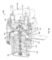
- FIG. 6A is a cross sectional view of a flow valve according to certain aspects of the present disclosure.
- FIG. 6B is a cross sectional view of a flow valve according to certain aspects of the present disclosure.
- FIG. 7 is a schematic representation of a ventilator according to certain aspects of the present disclosure.
- FIG. 8 shows a flowchart of a process for controlling a flow valve according to certain aspects of the present disclosure.
- FIG. 9 illustrates high frequency signals according to certain aspects of the present disclosure.
- gas shall be interpreted to mean both a single material in gaseous form, for example oxygen, and a mixture of two or more gases, for example air or heliox (a mixture of oxygen and helium).
- a gas may include water or other liquids in the form of vapor or suspended droplets.
- a gas may also include solid particulates suspended in the gas.
- pure when used with reference to a gas, means that the gas meets commonly accepted medical standards for purity and content.
- temperature sensor means a device configured to measure temperature and to provide a signal that is related to the measured temperature.
- a temperature sensor may include electronics to provide a drive current or voltage and/or measure a current or voltage.
- the electronics may further include conditioning and conversion circuitry and/or a processor to convert the measured value to a signal that may be in analog or digital form.
- pressure sensor means a device configured to measure a gas pressure and provide a signal that is related to the measured pressure.
- a pressure sensor may include electronics to provide a drive current or voltage and/or measure a current or voltage.
- the electronics may further include conditioning and conversion circuitry and/or a processor to convert the measured value to a signal that may be in analog or digital form.
- the pressure may be provided in absolute terms or “gauge” pressure, i.e., relative to ambient atmospheric pressure.
- valves having one or more valves that are software-controlled valves. These valves may be used to adjust the flow of gas passing through a port of the ventilator and can be configured to be positioned on the exhalation side of a ventilation system (meaning in connection with system components that receive exhaled air from a patient) or on an inhalation side of a ventilation system (meaning in connection with system components that provide air to a patient).
- the valves can be controlled by a software control signal and work in conjunction with a ventilator's gas delivery subsystems to maintain user set pressure control levels.
- an exhalation valve preferably maintains a set pressure, and outlet flow is controlled at a specified target bias flow rate. Additional (demand) flow may be provided through an inhalation valve to control the pressure.
- An exhalation subsystem of a ventilator comprises an exhalation valve, an exhalation flow sensor, and a heated filter and water trap.
- the exhalation valve is a software-controlled valve that is used to adjust the flow of gas passing through the expiratory port of the ventilator to the outside environment.
- the exhalation valve is controlled by a software control signal and works in conjunction with a ventilator's gas delivery subsystems to maintain user set pressure control levels.
- the exhalation valve operates on the principle of a force balance across a control diaphragm, which may be a disposable valve membrane.
- a linear magneto-mechanical actuator controls a force on the diaphragm, which in turn controls the circuit or ventilator line pressure.
- the force generated by the actuator is based on a command from the software closed-loop controller.
- FIG. 1 depicts a patient 10 using an exemplary ventilation system with a ventilator 100 according to certain aspects of the present disclosure.
- the ventilator 100 operates as a gas source for providing gas to a patient (e.g., for respiration).
- the ventilator system includes a supply channel, tube, or “limb” 104 , a return or exhaust channel, tube, or limb 106 , a conditioning module 108 that may, for example, warm or humidify the air passing through the supply limb 104 .
- the supply and exhaust limbs 104 , 106 are both coupled to a patient interface device 102 that, in this example, is a mask that fits over the mouth of the patient 10 .
- the patient interface device 102 may include a nasal mask, an intubation device, or any other breathing interface device as known to those of skill in the art.
- FIGS. 2A and 2B are front and rear views of the ventilator 100 according to certain aspects of the present disclosure.
- the ventilator 100 has a housing 110 with an attached user interface 115 that, in certain embodiments, comprises a display and a touchscreen.
- the front of the housing 110 includes a supply port 155 for a supply limb, such as supply limb 104 in FIG. 1 , and a return port 150 for an exhaust, such as exhaust limb 106 in FIG. 1 .
- the return port 150 may be mounted over an access door 152 that provides access to a filter (not visible in FIG. 2A ) that filters and absorbs moisture from the exhaled breath of the patient 10 .
- FIG. 2B shows a rear view of the ventilator 100 with a gas inlet adapter 120 , an air intake port 140 , and a power interface 130 that may include a power plug connector and a circuit breaker reset switch. There may also be a rear interface panel 165 for connection to external instruments or a network interface cable.
- FIG. 3 illustrates a schematic depiction of the ventilator 100 having a control system 305 , system hardware 310 , user input 315 , output 320 , and feedback 325 .
- the control system 305 includes a ventilation control system 330 that receives user input 315 .
- the control system 305 includes hardware control systems that control respective hardware components of the ventilator 100 .
- the hardware control systems may include a blower control system 335 , a flow cassette control system 340 , and an exhalation valve control system 345 .
- the blower control system 335 controls a respective blower 350
- the flow cassette control system 340 controls a respective flow cassette 355
- the exhalation valve control system 345 controls a respective exhalation valve 360 .
- the system hardware 310 includes sensors 365 that detect information from the system hardware 310 , for example, the blower 350 , the flow cassette 355 , and the exhalation valve 360 .
- the sensors 365 produce one or more feedback signals 325 that are received by the ventilation control system 330 .
- the ventilation control system 330 receives the feedback control signals 325 and the user input 315 and sends information to an output 320 .
- the output 320 can include, for example, monitoring information and alarms.
- FIG. 4A illustrates a schematic depiction of an exhalation control feedback system 400 that determines an amount of gas flow 405 that is permitted to pass through an exhalation valve 410 .
- the illustrated embodiment of the feedback system 400 is based on a target pressure 420 and an actual circuit pressure 425 (or a pressure within a line of the ventilator 100 ).
- a processor 430 receives an input signal relating to the actual circuit pressure 425 and compares the actual circuit pressure 425 to the target pressure 420 . Based on this comparison, the processor 430 sends a command signal 435 to an exhalation valve driver 440 .
- the exhalation valve driver 440 is configured to control a position of the exhalation valve 410 to regulate the gas flow 405 through the exhalation valve 410 .
- the exhalation valve driver 440 sends a control current 445 to the exhalation valve 410 to maintain or adjust the exhalation valve 410 to modify or adjust the pressure within the ventilator line.
- the processor 430 sends a command 435 to the exhalation valve driver 440 to open the exhalation valve 410 to reduce pressure within the ventilator line.
- the exhalation valve driver 440 upon receiving the command 435 to relieve pressure, adjusts the control current 445 to the exhalation valve 410 to increase the opening of the exhalation valve 410 and relieve pressure within the ventilator line.
- the processor 430 receives position feedback 450 of the exhalation valve 410 via the exhalation valve driver 440 , such that the processor 430 is able to determine the degree to which the exhalation valve 410 is open.
- the processor 430 directs the driver 440 to adjust the control current 445 to the exhalation valve 410 to decrease the opening of the exhalation valve 410 such that pressure within the ventilator line is increased. If the actual circuit pressure 425 input to the processor 430 was found to be at an acceptable level or within an acceptable range, the processor 430 directs the driver 440 to maintain the control current 445 to the exhalation valve 410 to maintain the position of the exhalation valve 410 .
- FIG. 4B illustrates a schematic depiction of an inhalation control feedback system 401 that determines an amount of gas flow 406 that is permitted to pass through an inhalation valve 411 .
- the illustrated embodiment of the feedback system 401 is based on a target flow 421 and an actual flow 426 (or a flow within a line of the ventilator 100 ).
- the position feedback may be used to determine flow, using the orifice characteristics of the valve and generally understood principles of fluid flow.
- Multiple gas types may be controlled based on the identified gas type (or gas id).
- the primary advantage of this flow measurement method is that the need for a separate flow sensor is eliminated and the resulting package provides for a compact flow delivery system.
- a processor 431 receives an input signal relating to the actual flow 426 and compares the actual flow 426 to the target flow 421 . Based on this comparison, the processor 431 sends a command signal 436 to an inhalation valve driver 441 .
- the inhalation valve driver 441 is configured to control a position of the inhalation valve 411 to regulate the gas flow 406 through the inhalation valve 411 .
- the inhalation valve driver 441 sends a control current 446 to the inhalation valve 411 to maintain or adjust the inhalation valve 411 to modify or adjust the flow rate through the ventilator line.
- the processor 431 sends a command 436 to the inhalation valve driver 441 to close the inhalation valve 411 to reduce the flow rate through the ventilator line.
- the inhalation valve driver 441 upon receiving the command 436 to reduce the flow rate, adjusts the control current 446 to the inhalation valve 411 to decrease the opening of the inhalation valve 411 and reduce the flow rate within the ventilator line.
- the processor 431 receives position feedback 451 of the inhalation valve 411 via the inhalation valve driver 441 , such that the processor 431 is able to determine the degree to which the inhalation valve 411 is open.
- the processor 431 directs the inhalation driver 441 to adjust the control current 446 to the inhalation valve 411 to increase the opening of the inhalation valve 411 such that the flow rate through the ventilator line is increased. If the actual flow 426 input to the processor 431 was found to be at an acceptable level or within an acceptable range, the processor 431 directs the driver 441 to maintain the control current 446 to the inhalation valve 411 to maintain the position of the inhalation valve 411 .
- FIG. 5 illustrates an exemplary schematic arrangement of a current control system 500 that illustrates some embodiments of a driver (e.g., the exhalation valve driver 440 of FIG. 4A or the inhalation valve driver 441 of FIG. 4B ) operating to adjust a valve 503 (e.g., the exhalation valve 410 or the inhalation valve 411 ).
- a driver e.g., the exhalation valve driver 440 of FIG. 4A or the inhalation valve driver 441 of FIG. 4B
- a valve 503 e.g., the exhalation valve 410 or the inhalation valve 411
- a high frequency source 505 generates a signal having a high frequency
- a low frequency source 510 generates a signal having a low frequency.
- the high frequency signal and the low frequency signal are summed together, and the signal is amplified by a current amplifier 515 .
- the current amplifier 515 is a linear current output amplifier.
- the signal is then directed to a coil 520 (e.g., a force coil) that is configured to move at least partly within a fixed magnetic field 525 .
- the fixed magnetic field 525 is produced by a magnetic field generator, e.g., at least one permanent magnet 530 or a separate coil (not shown).
- the natural frequency of the coil 520 is such that the coil 520 responds to the low frequency component of the combined signal by movement within or in relation to the magnetic field, as illustrated by arrows 535 .
- the low frequency component is less than about 90% of the natural frequency of the coil 520 .
- the low frequency component is less than about 80% of the natural frequency of the coil 520 , and in yet further embodiments, the low frequency component is less than about 50% of the natural frequency of the coil 520 .
- the high frequency component of the combined signal preferably has a negligible effect on the position of the coil 520 such that the position of the coil 520 within the magnetic field is controlled substantially by the low frequency component.
- the high frequency component is more than 50% greater than the natural frequency of the coil 520 .
- the high frequency component can be between 50% and about 200% greater than the natural frequency of the coil 520 .
- the high frequency can be more than 200% greater than the natural frequency of the coil 520 .
- a detection coil 540 detects the high frequency component of the signal passing through the coil 520 , and the detection coil 540 sends a signal to a high frequency feedback processor 545 that determines, based on the detection coil 540 signal, a position of the coil 520 within the magnetic field 525 .
- a magnitude of the high frequency signal detected by the detection coil 540 is used to determine the position of the coil 520 within the magnetic field 525 .
- the high frequency feedback processor 545 also determines a velocity of the coil 520 within the magnetic field 525 and the high frequency feedback processor 545 sends a signal to the low frequency source 510 for providing feedback on the position and/or velocity of the coil 520 .
- the high frequency feedback processor 545 includes a position circuit 547 and a velocity circuit 548 .
- the low frequency source 510 also receives input from a sensor (not shown) within a ventilator line relating to how an actual condition 550 (e.g., pressure or flow rate) within the ventilator line compares to a target condition 555 of the ventilator line. Based on (i) the input relating to the comparison of actual condition 550 and the target condition 555 and (ii) the input from the high frequency feedback processor 545 relating to the position of the coil 520 in relation to the magnetic field 525 , the low frequency source 510 determines whether the low frequency signal should be modified to change the position of the coil 520 in relation to the magnetic field 525 .
- a sensor not shown
- an actual condition 550 e.g., pressure or flow rate
- the low frequency source 510 changes the low frequency signal to move the coil 520 within the magnetic field 525 .
- the coil 520 is preferably coupled, directly (e.g., mechanically) or indirectly (e.g., magnetically), to a portion of the valve 503 that regulates flow through the valve 503 . Accordingly, movement of the coil 520 moves the portion of the valve 503 and changes an amount of gas passing through the valve 503 . As the amount of gas passing through the valve 503 changes, the detected condition within the ventilator line changes, and the actual condition 550 is detected and compared with the target condition 555 .
- the target condition 555 may include a minimum threshold pressure.
- the low frequency source 510 may be configured to close the valve 503 , such that substantially no gas from the exhalation line passes through the valve 503 .
- the valve 503 may remain closed until the actual condition 550 within the exhalation line increases above the threshold pressure, at which time, the low frequency source 510 receives inputs reflecting that the valve 503 should be opened, and the source 510 changes the low frequency signal to move the coil 520 to a position in relation to the magnetic field 525 that corresponds to an opening of the valve 503 .
- the low frequency source 510 may produce a signal that maintains position of the coil 520 , and therefore the valve 503 , to further increase the actual pressure within the exhalation line.
- the target condition 555 may include a threshold time of flow rate.
- the low frequency source 510 may be configured to close the valve 503 , such that substantially no gas from the inhalation line passes through the valve 503 .
- the valve 503 may remain closed until the next cycle, at which time, the low frequency source 510 receives inputs reflecting that the valve 503 should be opened, and the source 510 changes the low frequency signal to move the coil 520 to a position in relation to the magnetic field 525 that corresponds to an opening of the valve 503 .
- the low frequency source 510 may produce a signal that maintains position of the coil 520 , and therefore the valve 503 , to maintain the flow rate through the inhalation line.
- FIG. 6A is an exemplary cross sectional view of the a valve 600 A, which may be the exhalation valve 410 or the inhalation valve 411 , and operates under the same or similar principles described above with respect to valve 503 depicted in FIG. 5 .
- the illustrated valve 600 A includes a housing 605 that defines an internal chamber 610 . Disposed within the internal chamber 610 is a coil 615 that is positioned and axially movable within or in relation to a fixed magnetic field generator 620 .
- An armature 650 has a pole piece and may include or be attached to the coil 615 .
- Positioned about at least a portion of the magnetic field generator 620 is a sensor 625 .
- the senor 625 is a detection coil that is configured to detect high frequency signals passing through the coil 615 .
- the high frequency signals detected by the sensor 625 are used to determine a position of the coil 615 within or in relation to the magnetic field generator 620 .
- a signal is communicated from the sensor 625 regarding a position of the coil 615 , and signals are directed to the coil 615 via a flexible communication cable 630 .
- signals directed to the coil 615 cause the coil 615 to move within the internal chamber 610 in relation to the magnetic field, movement of the coil 615 affects positioning of a convoluted diaphragm 635 and poppet 647 or seal.
- the poppet 647 operates as a variable orifice of the valve 600 . Positioning of the poppet 647 with respect to the seat 645 affects the amount of fluid that passes through a valve having an opening 640 .
- Movement of the coil 615 can change a position of the sensor 625 by being directly coupled to the poppet 647 and moving the poppet 647 toward or away from a seat 645 , which defines the valve orifice as the gap between the poppet 647 and seat 645 .
- the armature 650 may be directly connected to the diaphragm 635 and/or the poppet 647 .
- movement of the coil 615 can change a position of the poppet 647 by being indirectly coupled to the poppet 647 .
- a portion of the coil 615 and a portion of the poppet 647 may be magnetically opposed or attracted to each other.
- this indirect coupling can affect positioning of the poppet 647 in connection with the seat 645 of the valve without contact between the coil 615 and the poppet 647 .
- valves that can be used include, but are not limited to, a flap valve, a rotating disk valve, a duck-billed valve, etc.
- the valve 600 A can also provide increased stability by damping the moving components of the valve 600 A.
- a velocity of the coil 615 can be determined by a processor (e.g., processor 430 or 431 or high frequency feedback processor 545 ), which can include a velocity circuit that calculates a change of position with respect to time. The velocity can then be used to determine the desired damping.
- the damped frequency response is greater than or equal to about 40 Hz, and the damping coefficient that yields an under-damped or critically damped valve assembly.
- additional damping such as pneumatic viscous damping can be incorporated into the valve 600 A to further tune the valve 600 A to the specific application.
- the valve 600 A can include a “fail-safe” open feature in case of loss of electrical power, software control, or loss of all inlet gases.
- the valve 600 A can also be configured to switch to the “fail-safe” open configuration when the ventilator 100 is turned off.
- the ventilator 100 On successful completion of power on checks, the ventilator 100 will close the valve 600 A and normal ventilation can commence.
- the valve 600 A, and other valves or ports will work in conjunction to (i) relieve pressure from the circuit down to ambient pressure conditions, (ii) allow ambient air to be available to the patient for breathing, and (iii) minimize re-breathing of gases.
- FIG. 6B illustrates a valve 600 B, which may be another implementation of the valve 600 A.
- the valve 600 B may comprise similar components as the valve 600 A.
- the valve 600 B comprises a front flat spring 652 , and a rear flat spring 654 .
- the front flat spring 652 and the rear flat spring 654 provide mechanical or structural support for the armature 650 .
- the armature 650 may be supported by other structures, such as bearings.
- FIG. 7 illustrates a schematic depiction of another implementation of the ventilator 100 having a control system 705 , system hardware 710 , user input 715 , output 720 , and feedback 725 .
- the control system 705 includes a ventilation control system 730 that receives user input 715 .
- the control system 705 includes hardware control systems that control respective hardware components of the ventilator 100 .
- the hardware control systems may include a blower control system 735 , an inflow valve control system 740 , and an exhalation valve control system 745 .
- the blower control system 735 controls a respective blower 750
- the inflow valve control system 740 controls a respective inflow valve 755
- the exhalation valve control system 745 controls a respective exhalation valve 760 .
- the system hardware 710 includes sensors 765 that detect information from the system hardware 710 , for example, the blower 750 , the inflow valve 755 , and the exhalation valve 760 .
- the sensors 765 produce one or more feedback signals 725 that are received by the ventilation control system 730 .
- the ventilation control system 730 receives the feedback control signals 725 and the user input 715 and sends information to an output 720 .
- the output 720 can include, for example, monitoring information and alarms.
- the inflow valve control system 740 may be similar to and operate similarly to the exhalation valve control system 745 , which may correspond to the feedback system 400 in FIG. 4 or the current control system 500 in FIG. 5 .
- the inflow valve 755 may also be similar to and operate similarly to the exhalation valve 760 , which may correspond to the exhalation valve 410 in FIGS. 4 and 6 , or the valve 503 in FIG. 5 .
- the inflow valve 755 may be any front end valve before the patient in a gas flow.
- the exhalation valve 760 may be any back end valve behind the patient in a gas flow.
- a flow cassette may include a pressure measurement device for an inlet gas, which measures pressure differential to determine flow measurement.
- the flow cassette may also include another valve tracker that drives the flow control valve of the flow cassette.
- valve control systems described herein provide flow control through the variable valve opening, but also provide flow measurement.
- the flow measurement can be derived from the position of the force coil or drive coil.
- the valve control systems also provide flow measurement and flow control, similar to flow cassettes.
- flow cassettes may be cost prohibitive for certain applications.
- a ventilator system with valve control systems may be less expensive to produce than a ventilator system with one or more flow cassettes.
- the valve control systems may be different sizes, for example one quarter of the size of the other, as needed.
- the two valve control systems can work together, with one for inspiration and one for exhalation.
- the inflow valve 755 may be open and regulated until an appropriate volume of gas has flowed to the patient.
- the inflow valve 755 will then close, and the exhalation valve 760 will open, and regulated until an appropriate volume of gas has been exhaled by the patient.
- gas is connected to the inflow valve 755 which starts closed, building up high pressure.
- the inflow valve control system 740 commands the inflow valve 755 to open, allowing the flow through to the patient.
- inspiration starts, the exhalation valve 760 is closed.
- the inflow valve control system 740 determines when to close the inflow valve 755 based on a flow control or a pressure control.
- the exhalation valve control system 745 commands the exhalation valve 760 to open, allowing the patient to breathe out.
- the inflow valve 755 is directed to open, and the cycle repeats.
- Flow control may be calculated by sampling, for instance, the pressure every millisecond to make adjustments. Based on the position of the drive coil, the pressure can be calculated.
- the pressure is continuously monitored to adjust the position of the drive coil until a target flow is reached.
- the calculations may factor in ambient pressure, gas composition, gas temperature changes, downstream pressure changes, inlet pressure changes, etc. The calculations may further correct for standard conditions.
- the exhalation valve 760 allows the patient to exhale without difficulty.
- flow control devices described herein may be used in connection CPAP therapy, other embodiments, particularly embodiments used on the front end of the ventilator, are not limited to CPAP therapy.
- the flow control devices described herein may be utilized at any point along a flow path of a ventilator, respirator, or other similar device.
- the flow control devices may be used in other fluid devices, particularly fluid devices which measure and/or regulate fluid flow, and are not limited to respiration.
- FIG. 8 shows a flowchart 800 of controlling a flow valve, such as the valve 503 .
- a high frequency signal and a low frequency signal is sent to a drive coil, such as the coil 615 .
- the low frequency signal causes the drive coil to move within a fixed magnetic field, such as the fixed magnetic field generator 620 .
- the moved drive coil causes a movable part, such as the poppet 647 or seal, to adjust a valve orifice of the valve, such as the opening 640 .
- the high frequency signal in the moved drive coil is detected.
- a velocity of the drive coil is determined based on the detected high frequency signal.
- the low frequency signal is modified based on the determined velocity of the drive coil. For example, the velocity signal may be injected into the low frequency source for the purpose of dampening.
- the block 830 may be expanded into several operations, denoted by the dotted lines in FIG. 8 .
- a delay between the high frequency signal and the detected high frequency signal may be determined.
- FIG. 9 shows a sample space 900 .
- a high frequency signal 910 which may be a high frequency current from the high frequency source 505
- a detected high frequency signal 920 which may be a high frequency current detected in the drive coil after the drive coil moves.
- a delay 930 between the signals may be proportional to the position of the drive coil.
- the position of the drive coil is determined based on the delay.
- the velocity of the drive coil is determined based on the position of the drive coil.
- the low frequency signal may be modified based on the determined velocity of the drive coil to, for example, control dampening of the drive coil.
- top should be understood as referring to an arbitrary frame of reference, rather than to the ordinary gravitational frame of reference.
- a top surface, a bottom surface, a front surface, and a rear surface may extend upwardly, downwardly, diagonally, or horizontally in a gravitational frame of reference.
- a phrase such as an “aspect” does not imply that such aspect is essential to the subject technology or that such aspect applies to all configurations of the subject technology.
- a disclosure relating to an aspect may apply to all configurations, or one or more configurations.
- a phrase such as an aspect may refer to one or more aspects and vice versa.
- a phrase such as an “embodiment” does not imply that such embodiment is essential to the subject technology or that such embodiment applies to all configurations of the subject technology.
- a disclosure relating to an embodiment may apply to all embodiments, or one or more embodiments.
- a phrase such an embodiment may refer to one or more embodiments and vice versa.
- a flow control device comprising: a high frequency source configured to generate a high frequency signal; a low frequency source configured to generate a low frequency signal; a fixed magnetic field; a drive coil configured to move within the fixed magnetic field in response to the low frequency signal and configured to receive the high frequency signal; a detection coil adjacent the drive coil and configured to detect the high frequency signal in the drive coil, the detected high frequency signal corresponding to a position of the drive coil; a processor coupled to the high frequency source and the low frequency source and configured to receive the detected high frequency signal from the detection coil; a seal configured to move based on the position of the drive coil; and a valve orifice defining a valve seat and a variable opening, the variable opening being adjustable based on a position of the seal relative to the valve seat.
- a ventilator system comprising: a first valve connected to a supply channel and comprising: a first high frequency source configured to generate a first high frequency signal; a first low frequency source configured to generate a first low frequency signal; a first fixed magnetic field; a first drive coil configured to move within the first fixed magnetic field in response to the first low frequency signal and configured to receive the first high frequency signal; a first detection coil adjacent the first drive coil and configured to detect the first high frequency signal in the drive coil, the detected first high frequency signal corresponding to a position of the first drive coil; a first processor coupled to the first high frequency source and the first low frequency source and configured to receive the detected first high frequency signal from the first detection coil; a first seal configured to move based on the position of the first drive coil; and a variable first valve orifice defining a first valve seat, the first valve orifice being adjustable based on a position of the first seal relative to the first valve seat.
- first processor further comprises a first position circuit configured to calculate the position of the first drive coil based on a delay between the first high frequency signal and the detected first high frequency signal, and wherein the delay is proportional to the position of the first drive coil.
- first processor further comprises a first velocity circuit configured to calculate a velocity of the first drive coil based on the calculated position of the first drive coil.
- the second processor further comprises a second position circuit configured to calculate the position of the second drive coil based on a delay between the second high frequency signal and the detected second high frequency signal, and wherein the delay is proportional to the position of the second drive coil.
- a method for adjusting a valve comprising: sending a high frequency signal and a low frequency signal to a drive coil, the low frequency signal causing the drive coil to move within a fixed magnetic field, the drive coil causing a seal to adjust a variable valve orifice of the valve; detecting the high frequency signal in the drive coil; determining a velocity of the drive coil based on the detected high frequency signal; and modifying the low frequency signal based on the determined velocity of the drive coil.
- determining the velocity further comprises: determining a delay between the high frequency signal and the detected high frequency signal; determining a position of the drive coil based on the delay; and determining a change of position of the drive coil over a change in time
Abstract
Description
Claims (18)
Priority Applications (9)
| Application Number | Priority Date | Filing Date | Title |
|---|---|---|---|
| US14/318,274 US9962514B2 (en) | 2013-06-28 | 2014-06-27 | Ventilator flow valve |
| PCT/US2015/038157 WO2015200878A1 (en) | 2014-06-27 | 2015-06-26 | Ventilator flow valve |
| JP2017520764A JP2017522157A (en) | 2014-06-27 | 2015-06-26 | Ventilator flow valve |
| CA2952746A CA2952746A1 (en) | 2014-06-27 | 2015-06-26 | Ventilator flow valve |
| EP15741681.9A EP3160561B1 (en) | 2014-06-27 | 2015-06-26 | Ventilator flow valve |
| AU2015279626A AU2015279626A1 (en) | 2014-06-27 | 2015-06-26 | Ventilator flow valve |
| MX2016016197A MX2016016197A (en) | 2014-06-27 | 2015-06-26 | Ventilator flow valve. |
| CN201580034928.4A CN106573124A (en) | 2014-06-27 | 2015-06-26 | Ventilator flow valve |
| EP18159740.2A EP3351281A1 (en) | 2014-06-27 | 2015-06-26 | Ventilator flow valve |
Applications Claiming Priority (2)
| Application Number | Priority Date | Filing Date | Title |
|---|---|---|---|
| US13/931,418 US9433743B2 (en) | 2013-06-28 | 2013-06-28 | Ventilator exhalation flow valve |
| US14/318,274 US9962514B2 (en) | 2013-06-28 | 2014-06-27 | Ventilator flow valve |
Related Parent Applications (1)
| Application Number | Title | Priority Date | Filing Date |
|---|---|---|---|
| US13/931,418 Continuation-In-Part US9433743B2 (en) | 2013-06-28 | 2013-06-28 | Ventilator exhalation flow valve |
Publications (2)
| Publication Number | Publication Date |
|---|---|
| US20150000663A1 US20150000663A1 (en) | 2015-01-01 |
| US9962514B2 true US9962514B2 (en) | 2018-05-08 |
Family
ID=52114384
Family Applications (1)
| Application Number | Title | Priority Date | Filing Date |
|---|---|---|---|
| US14/318,274 Expired - Fee Related US9962514B2 (en) | 2013-06-28 | 2014-06-27 | Ventilator flow valve |
Country Status (1)
| Country | Link |
|---|---|
| US (1) | US9962514B2 (en) |
Cited By (5)
| Publication number | Priority date | Publication date | Assignee | Title |
|---|---|---|---|---|
| US11247008B1 (en) | 2020-08-05 | 2022-02-15 | Effortless Oxygen, Llc | Flow triggered gas delivery |
| US11278700B2 (en) | 2015-06-24 | 2022-03-22 | Fisher & Paykel Healthcare Limited | Breathing assistance apparatus |
| US11318276B2 (en) | 2020-08-05 | 2022-05-03 | Effortless Oxygen, Llc | Flow triggered gas delivery |
| US11420007B2 (en) | 2020-08-05 | 2022-08-23 | Effortless Oxygen, Llc | Flow triggered gas delivery |
| US20230233792A1 (en) * | 2021-09-02 | 2023-07-27 | Ryan Redford | Ventilation system with improved valving |
Families Citing this family (6)
| Publication number | Priority date | Publication date | Assignee | Title |
|---|---|---|---|---|
| CN113007106B (en) | 2011-07-13 | 2023-08-11 | 费雪派克医疗保健有限公司 | Impeller and motor assembly |
| CN205515844U (en) | 2012-12-18 | 2016-08-31 | 费雪派克医疗保健有限公司 | Breathe auxiliary device and be used for assembly of motor |
| CN104645471A (en) * | 2015-02-13 | 2015-05-27 | 齐倩 | Non-invasive continuous positive airway pressure breathing machine for children |
| EP3355976B1 (en) | 2015-09-29 | 2021-09-22 | Koninklijke Philips N.V. | Non-therapeutic method of pressure and gas mix control for non-invasive ventilation, and ventilator for non-invasive ventilation |
| DE102016220812A1 (en) * | 2016-10-24 | 2018-04-26 | Hamilton Medical Ag | Exhalation valve for a ventilator with low-noise valve design |
| CN114288513A (en) | 2017-04-23 | 2022-04-08 | 费雪派克医疗保健有限公司 | Breathing assistance apparatus |
Citations (127)
| Publication number | Priority date | Publication date | Assignee | Title |
|---|---|---|---|---|
| US2037880A (en) | 1933-11-17 | 1936-04-21 | Hartzell Industries | Fan |
| US2510125A (en) | 1946-07-30 | 1950-06-06 | Lawrence W Meakin | Connector for fluid or electrical lines or both |
| US2634311A (en) | 1950-01-31 | 1953-04-07 | Ralph E Darling | Composite fluid and electrical connector |
| US3140042A (en) | 1961-08-15 | 1964-07-07 | Fujii Noriyoshi | Wheels for centrifugal fans of the forward curved multiblade type |
| US3673541A (en) | 1970-08-06 | 1972-06-27 | Amp Inc | Composite electrical and fluid or air connector |
| US3776215A (en) | 1971-11-01 | 1973-12-04 | Hugh J Mc | Humidifier means |
| US3788765A (en) | 1971-11-18 | 1974-01-29 | Laval Turbine | Low specific speed compressor |
| US4167369A (en) | 1977-04-04 | 1979-09-11 | Kabushiki Kaisha Komatsu Seisakusho | Impeller blading of a centrifugal compressor |
| US4243357A (en) | 1979-08-06 | 1981-01-06 | Cummins Engine Company, Inc. | Turbomachine |
| US4381668A (en) | 1979-08-22 | 1983-05-03 | Hitachi, Ltd. | Gas flow measuring apparatus |
| US4543041A (en) | 1981-08-07 | 1985-09-24 | Holset Engineering Company Limited | Impellor for centrifugal compressor |
| US4562744A (en) | 1984-05-04 | 1986-01-07 | Precision Measurement, Inc. | Method and apparatus for measuring the flowrate of compressible fluids |
| US4571801A (en) | 1983-06-15 | 1986-02-25 | Mks Instruments, Inc. | Method of manufacturing a cartridge unit for establishing controlled laminar-flow conditions |
| US4649760A (en) | 1985-04-18 | 1987-03-17 | Wedding James B | Method and apparatus for controlling flow volume through an aerosol sampler |
| US4754651A (en) | 1986-04-18 | 1988-07-05 | Shortridge Instruments, Inc. | Differential pressure apparatus for measuring flow and velocity |
| US4763645A (en) | 1987-08-25 | 1988-08-16 | Kapp Michael J | Tracheal tube filter |
| US4809742A (en) | 1988-04-18 | 1989-03-07 | Pneumo Abex Corporation | Control valve assembly including valve position sensor |
| US4825904A (en) | 1988-04-18 | 1989-05-02 | Pneumo Abex Corporation | Two position flow control valve assembly with position sensing |
| US4909545A (en) | 1982-12-15 | 1990-03-20 | Larry Hohol | Coupling |
| CN1041204A (en) | 1988-06-17 | 1990-04-11 | 松下电器产业株式会社 | The impeller of multiblade blower |
| US4978281A (en) | 1988-08-19 | 1990-12-18 | Conger William W Iv | Vibration dampened blower |
| US5127400A (en) | 1990-03-23 | 1992-07-07 | Bird Products Corp. | Ventilator exhalation valve |
| US5190068A (en) | 1992-07-02 | 1993-03-02 | Brian Philbin | Control apparatus and method for controlling fluid flows and pressures |
| JPH0556597A (en) | 1991-08-23 | 1993-03-05 | Canon Inc | Structure for fixing bearing of motor |
| US5207239A (en) * | 1991-07-30 | 1993-05-04 | Aura Systems, Inc. | Variable gain servo assist |
| US5265594A (en) | 1990-10-30 | 1993-11-30 | Siemens Aktiengesellschaft | Apparatus for regulating the flow-through amount of a flowing medium |
| US5277196A (en) | 1992-03-31 | 1994-01-11 | The United States Of America As Represented By The Department Of Health And Human Services | Portable spirometer with improved accuracy |
| US5295397A (en) | 1991-07-15 | 1994-03-22 | The Texas A & M University System | Slotted orifice flowmeter |
| US5331995A (en) | 1992-07-17 | 1994-07-26 | Bear Medical Systems, Inc. | Flow control system for medical ventilator |
| US5339807A (en) | 1992-09-22 | 1994-08-23 | Puritan-Bennett Corporation | Exhalation valve stabilizing apparatus |
| US5365795A (en) | 1993-05-20 | 1994-11-22 | Brower Jr William B | Improved method for determining flow rates in venturis, orifices and flow nozzles involving total pressure and static pressure measurements |
| US5461932A (en) | 1991-07-15 | 1995-10-31 | Texas A & M University System | Slotted orifice flowmeter |
| US5478206A (en) | 1991-03-23 | 1995-12-26 | Robert Bosch Gmbh | Impeller for a radial fan |
| US5537992A (en) | 1994-05-06 | 1996-07-23 | Siemens Elema Ab | Anesthetic system having electronic safety interlock system |
| US5572992A (en) | 1994-03-04 | 1996-11-12 | Instrumentarium Corp. | Method and apparatus for identifying an anesthetic fluid container and/or for detecting a connection between the container and a conduit supplying a gas to a patient |
| US5604681A (en) | 1994-06-03 | 1997-02-18 | Dover Corporation | Coupler identification systems |
| US5606236A (en) | 1995-01-17 | 1997-02-25 | Eaton Corporation | Two wire position sense and control of modulating gas valve or other electromechanical actuators |
| EP0829793A1 (en) | 1996-09-06 | 1998-03-18 | Berkin B.V. | Method for momentarily identifying a gas or liquid flow, and device for carrying out the method |
| US5771884A (en) | 1997-03-14 | 1998-06-30 | Nellcor Puritan Bennett Incorporated | Magnetic exhalation valve with compensation for temperature and patient airway pressure induced changes to the magnetic field |
| US5918596A (en) | 1997-04-22 | 1999-07-06 | Instrumentarium Corp. | Special gas dose delivery apparatus for respiration equipment |
| US5954051A (en) | 1997-02-06 | 1999-09-21 | Instrumentarium Oy | Ventilator for intensified breathing and valve in patient conduit of apparatus for intensified breathing |
| US6017315A (en) | 1998-02-25 | 2000-01-25 | Respironics, Inc. | Patient monitor and method of using same |
| US6139262A (en) | 1998-05-08 | 2000-10-31 | York International Corporation | Variable geometry diffuser |
| US6151557A (en) | 1998-01-13 | 2000-11-21 | Rosemount Inc. | Friction flowmeter with improved software |
| WO2001038832A2 (en) | 1999-11-24 | 2001-05-31 | S.C. Ack S.R.L. | System for metering fluids |
| EP1127583A2 (en) | 2000-02-24 | 2001-08-29 | Siemens-Elema AB | Conduit with transmission line |
| US20020085952A1 (en) | 2000-09-27 | 2002-07-04 | Ellingboe Bruce S. | Blood perfusion system |
| US6422256B1 (en) | 1998-10-08 | 2002-07-23 | Mott Metallurgical Corporation | Fluid flow controlling |
| US6422092B1 (en) | 1998-09-10 | 2002-07-23 | The Texas A&M University System | Multiple-phase flow meter |
| US20020198668A1 (en) | 2001-04-24 | 2002-12-26 | Lull John M. | System and method for a mass flow controller |
| US6553923B2 (en) | 2000-08-30 | 2003-04-29 | William Stuart Gatley, Jr. | Blower housing with maximized interior spacing |
| US20030106554A1 (en) | 2001-11-30 | 2003-06-12 | De Silva Adrian D. | Gas identification system and volumetric ally correct gas delivery system |
| US6578818B1 (en) | 1998-03-10 | 2003-06-17 | Robert Bosch Gmbh | Valve device |
| US6609431B1 (en) | 2000-09-29 | 2003-08-26 | Xellogy, Inc. | Flow measuring device based on predetermine class of liquid |
| US6622724B1 (en) | 2000-06-19 | 2003-09-23 | Respironics, Inc. | Impeller and a pressure support system and method using such an impeller |
| US20030220605A1 (en) | 2002-05-24 | 2003-11-27 | Bowman Joseph H. | Disposable medical fluid unit having rigid frame |
| US20040074311A1 (en) | 2002-07-19 | 2004-04-22 | Celerity Group, Inc. | Methods and apparatus for pressure compensation in a mass flow controller |
| US20040177703A1 (en) | 2003-03-12 | 2004-09-16 | Schumacher Mark S. | Flow instrument with multisensors |
| US20040187871A1 (en) | 2003-03-28 | 2004-09-30 | Ric Investments, Inc. | Pressure support compliance monitoring system |
| US6820620B2 (en) | 2000-12-22 | 2004-11-23 | Jean-Denis Rochat | Respiratory assistance apparatus |
| US20050004534A1 (en) | 2001-12-26 | 2005-01-06 | Lockwood Jeffery S | Vented vacuum bandage and method |
| US6945123B1 (en) | 2004-06-28 | 2005-09-20 | The General Electric Company | Gas flow sensor having redundant flow sensing capability |
| US20050241412A1 (en) | 2002-05-24 | 2005-11-03 | Tison Stuart A | Slotted flow restrictor for a mass flow meter |
| WO2006024532A1 (en) | 2004-09-03 | 2006-03-09 | Ric Investments, Llc | Gas flow control in a ventilator |
| US20060079765A1 (en) | 2004-10-13 | 2006-04-13 | Liebel-Flarsheim Company | Powerhead of a power injection system |
| EP1658874A2 (en) | 2004-11-22 | 2006-05-24 | Universitätsklinikum Erlangen | Gas valve, system of gas checking as well as method of checking a gas collectable through the valve |
| US20060144163A1 (en) | 2002-11-20 | 2006-07-06 | Harri Friberg | Gas flow measuring device |
| US20060162466A1 (en) | 2002-07-19 | 2006-07-27 | Christopher Wargo | Fluid flow measuring and proportional fluid flow control device |
| US7107834B2 (en) | 2004-11-12 | 2006-09-19 | Mks Instruments, Inc. | Thermal mass flow rate sensor including bypass passageways and a sensor passageway having similar entrance effects |
| US7121139B2 (en) | 2004-11-12 | 2006-10-17 | Mks Instruments, Inc. | Thermal mass flow rate sensor having fixed bypass ratio |
| US20060236781A1 (en) | 2003-07-03 | 2006-10-26 | Fujikin Incorporated | Differential pressure type flowmeter and differential pressure type flowmeter controller |
| US20070193369A1 (en) | 2006-02-15 | 2007-08-23 | Evans Russell N | Multiphasic overreading correction in a process variable transmitter |
| US20070265877A1 (en) | 2006-05-12 | 2007-11-15 | Rice Caeli B D | Informative accessories |
| US20070277824A1 (en) | 2006-05-31 | 2007-12-06 | Acoba, L.L.C. | Hose Connection System For Narially Sensitive Diagnostic Devices |
| US20080059084A1 (en) | 2006-09-05 | 2008-03-06 | Celerity, Inc. | Multi-gas flow device |
| CN101225881A (en) | 2007-12-19 | 2008-07-23 | 哈尔滨工业大学 | High speed electrohydraulic open and close valve driven directly by ultra-magnetostriction actuator |
| US20080283062A1 (en) | 2007-05-18 | 2008-11-20 | Esposito Jr Anthony J | Respiratory Component Measurement System |
| US20090038615A1 (en) | 2006-02-23 | 2009-02-12 | Meditren Limited | Breathing apparatus |
| US20090093774A1 (en) | 2007-10-04 | 2009-04-09 | Baxter International Inc. | Ambulatory pump with intelligent flow control |
| US20090095068A1 (en) | 2007-10-10 | 2009-04-16 | Celerity, Inc. | System for and method of providing a wide-range flow controller |
| US20090113996A1 (en) | 2007-10-04 | 2009-05-07 | Baxter International Inc. | System and method for measuring liquid viscosity in a fluid delivery system |
| US20090293634A1 (en) | 2008-05-27 | 2009-12-03 | Joo Tim Ong | Method of measuring multiphase flow |
| US20090326839A1 (en) | 2008-06-27 | 2009-12-31 | Steven Bruce Rogers | Velocity-enhanced flow measurement |
| US20100031737A1 (en) | 2008-08-11 | 2010-02-11 | Hitachi Automotive Systems, Ltd. | Mass air flow measurement device |
| CN101687086A (en) | 2007-06-28 | 2010-03-31 | 马奎特紧急护理公司 | A patient ventilation system with gas identification means |
| US20100139660A1 (en) | 2008-12-10 | 2010-06-10 | Carmeli Adahan | Pump and exhalation valve control for respirator apparatus |
| US20100229967A1 (en) | 2009-03-11 | 2010-09-16 | Horiba Stec, Co., Ltd. | Mass flow controller verifying system, verifying method and verifying program |
| US20100236552A1 (en) | 2005-08-15 | 2010-09-23 | Resmed Limited | Cpap Systems |
| US7819022B2 (en) | 2006-03-16 | 2010-10-26 | Sensorteknikk As | Method and device for recording characteristic state, amount and composition of a flowing medium |
| US7826986B2 (en) | 2008-09-26 | 2010-11-02 | Advanced Energy Industries, Inc. | Method and system for operating a mass flow controller |
| US20100307490A1 (en) | 2007-11-14 | 2010-12-09 | Stefan Broborg | Patient cassette with variable patient circuit volume |
| US20110100364A1 (en) | 2009-11-02 | 2011-05-05 | Joseph Dee Faram | Multiple conduit connector apparatus and method |
| WO2011055254A1 (en) | 2009-11-09 | 2011-05-12 | Koninklijke Philips Electronics N.V. | Flow sensing device with temperature compensation |
| US20110126837A1 (en) | 2009-12-01 | 2011-06-02 | Nellcor Puritan Bennett Llc | Exhalation Valve Assembly With Integrated Filter |
| US20110126834A1 (en) | 2009-12-01 | 2011-06-02 | Nellcor Puritan Bennett Llc | Exhalation Valve Assembly With Integral Flow Sensor |
| CN102155570A (en) | 2011-04-22 | 2011-08-17 | 浙江大学 | Pneumatic high-speed switch valve driven by giant magnetostriction |
| US20110301867A1 (en) | 2010-06-08 | 2011-12-08 | Rosemount Inc. | Fluid flow measurement with phase-based diagnostics |
| EP2402616A1 (en) | 2009-07-13 | 2012-01-04 | Mitsubishi Heavy Industries, Ltd. | Impeller and rotary machine |
| US20120065533A1 (en) | 2010-05-28 | 2012-03-15 | Carrillo Jr Oscar | Positive Airway Pressure System and Method |
| US20120085349A1 (en) | 2010-10-06 | 2012-04-12 | Honeywell International Inc. | Respirator with end-of-service-life detection |
| US20120185102A1 (en) | 2011-01-18 | 2012-07-19 | Flow Control Industries, Inc. | Pressure compensated flow rate controller with btu meter |
| CN202366282U (en) | 2011-12-04 | 2012-08-08 | 任梅 | Breathing device for emergency treatment |
| US20120204874A1 (en) | 2009-10-28 | 2012-08-16 | Koninklijke Philips Electronics N.V. | Pressure support sustem with inductive tubing |
| US20120229272A1 (en) | 2009-11-11 | 2012-09-13 | Koninklijke Philips Electronics N.V. | Wireless identification of a component of a pressure support system |
| CN102686888A (en) | 2009-10-29 | 2012-09-19 | 雷斯麦德有限公司 | Patient ventilation device and components thereof |
| US20120285455A1 (en) | 2011-05-11 | 2012-11-15 | Varga Christopher M | Smart connections |
| US20120318383A1 (en) | 2011-06-17 | 2012-12-20 | Horiba Stec, Co., Ltd. | Flow rate measuring device and flow rate controller |
| WO2013002699A1 (en) | 2011-06-30 | 2013-01-03 | Cejn Ab | Quick coupling for pipes/hoses with locking feature |
| CN102927292A (en) | 2012-11-01 | 2013-02-13 | 浙江理工大学 | Solenoid valve and weft yarn tension device |
| US20130036806A1 (en) | 2011-08-09 | 2013-02-14 | Denso Corporation | Air flow measuring device |
| US20130079667A1 (en) | 2011-09-28 | 2013-03-28 | General Electric Company | Flow sensor with mems sensing device and method for using same |
| CN202870631U (en) | 2012-10-16 | 2013-04-10 | 深圳市安保科技有限公司 | Respiratory flow adjusting device and respirator |
| CN103041492A (en) | 2012-12-29 | 2013-04-17 | 平湖市瑞阳精密机械有限公司 | Medical gas valve |
| WO2013080079A1 (en) | 2011-12-01 | 2013-06-06 | Koninklijke Philips Electronics N.V. | Systems and methods for using partial co2 rebreathing integrated in a ventilator and measurements thereof to determine noninvasive cardiac output |
| US20130153040A1 (en) | 2006-08-03 | 2013-06-20 | Hitachi Metals, Ltd. | Flow rate control using mass flow rate control device |
| US8504318B2 (en) | 2008-03-05 | 2013-08-06 | Brooks Instruments, Llc | System, method and computer program for determining fluid flow rate using a pressure sensor and a thermal mass flow sensor |
| US20130220314A1 (en) | 2012-02-29 | 2013-08-29 | General Electric Company | Medical vaporizer with porous vaporization element |
| US20130247905A1 (en) | 2010-12-03 | 2013-09-26 | Intersurgical Ag | Breathing systems |
| US20140054479A1 (en) | 2011-12-30 | 2014-02-27 | Beijing Aeonmed Co., Ltd. | Flow control proportional valve |
| US20140066880A1 (en) | 2011-06-22 | 2014-03-06 | Crisi Medical Systems, Inc. | Selectively Controlling Fluid Flow Through A Fluid Pathway |
| US20140182590A1 (en) | 2012-12-28 | 2014-07-03 | Newport Medical Instruments, Incorporated | Ventilator pressure oscillation filter |
| US20140251322A1 (en) | 2011-11-01 | 2014-09-11 | Intersurgical Ag | Breathing systems |
| US20150020807A1 (en) | 2012-02-29 | 2015-01-22 | Koninklijke Philips N.V. | Compensating for variations in air density in a pressure support device |
| US20150096560A1 (en) | 2012-04-27 | 2015-04-09 | Fisher & Paykel Place, East Limited | Usability features for respiratory humidification system |
| US9003877B2 (en) | 2010-06-15 | 2015-04-14 | Honeywell International Inc. | Flow sensor assembly |
| US20150143921A1 (en) | 2012-06-04 | 2015-05-28 | Hans-Jürgen Postberg | Device for measuring differential pressure |
| US20160256646A1 (en) | 2013-10-07 | 2016-09-08 | Endoclear Llc | Systems and methods for selectively blocking respiratory air flow |
-
2014
- 2014-06-27 US US14/318,274 patent/US9962514B2/en not_active Expired - Fee Related
Patent Citations (134)
| Publication number | Priority date | Publication date | Assignee | Title |
|---|---|---|---|---|
| US2037880A (en) | 1933-11-17 | 1936-04-21 | Hartzell Industries | Fan |
| US2510125A (en) | 1946-07-30 | 1950-06-06 | Lawrence W Meakin | Connector for fluid or electrical lines or both |
| US2634311A (en) | 1950-01-31 | 1953-04-07 | Ralph E Darling | Composite fluid and electrical connector |
| US3140042A (en) | 1961-08-15 | 1964-07-07 | Fujii Noriyoshi | Wheels for centrifugal fans of the forward curved multiblade type |
| US3673541A (en) | 1970-08-06 | 1972-06-27 | Amp Inc | Composite electrical and fluid or air connector |
| US3776215A (en) | 1971-11-01 | 1973-12-04 | Hugh J Mc | Humidifier means |
| US3788765A (en) | 1971-11-18 | 1974-01-29 | Laval Turbine | Low specific speed compressor |
| US4167369A (en) | 1977-04-04 | 1979-09-11 | Kabushiki Kaisha Komatsu Seisakusho | Impeller blading of a centrifugal compressor |
| US4243357A (en) | 1979-08-06 | 1981-01-06 | Cummins Engine Company, Inc. | Turbomachine |
| US4381668A (en) | 1979-08-22 | 1983-05-03 | Hitachi, Ltd. | Gas flow measuring apparatus |
| US4543041A (en) | 1981-08-07 | 1985-09-24 | Holset Engineering Company Limited | Impellor for centrifugal compressor |
| US4909545A (en) | 1982-12-15 | 1990-03-20 | Larry Hohol | Coupling |
| US4571801A (en) | 1983-06-15 | 1986-02-25 | Mks Instruments, Inc. | Method of manufacturing a cartridge unit for establishing controlled laminar-flow conditions |
| US4562744A (en) | 1984-05-04 | 1986-01-07 | Precision Measurement, Inc. | Method and apparatus for measuring the flowrate of compressible fluids |
| US4649760A (en) | 1985-04-18 | 1987-03-17 | Wedding James B | Method and apparatus for controlling flow volume through an aerosol sampler |
| US4754651A (en) | 1986-04-18 | 1988-07-05 | Shortridge Instruments, Inc. | Differential pressure apparatus for measuring flow and velocity |
| US4763645A (en) | 1987-08-25 | 1988-08-16 | Kapp Michael J | Tracheal tube filter |
| US4809742A (en) | 1988-04-18 | 1989-03-07 | Pneumo Abex Corporation | Control valve assembly including valve position sensor |
| US4825904A (en) | 1988-04-18 | 1989-05-02 | Pneumo Abex Corporation | Two position flow control valve assembly with position sensing |
| CN1041204A (en) | 1988-06-17 | 1990-04-11 | 松下电器产业株式会社 | The impeller of multiblade blower |
| US5064346A (en) | 1988-06-17 | 1991-11-12 | Matsushita Electric Industrial Co., Ltd. | Impeller of multiblade blower |
| US4978281A (en) | 1988-08-19 | 1990-12-18 | Conger William W Iv | Vibration dampened blower |
| US5127400A (en) | 1990-03-23 | 1992-07-07 | Bird Products Corp. | Ventilator exhalation valve |
| US5265594A (en) | 1990-10-30 | 1993-11-30 | Siemens Aktiengesellschaft | Apparatus for regulating the flow-through amount of a flowing medium |
| US5478206A (en) | 1991-03-23 | 1995-12-26 | Robert Bosch Gmbh | Impeller for a radial fan |
| US5295397A (en) | 1991-07-15 | 1994-03-22 | The Texas A & M University System | Slotted orifice flowmeter |
| US5461932A (en) | 1991-07-15 | 1995-10-31 | Texas A & M University System | Slotted orifice flowmeter |
| US5207239A (en) * | 1991-07-30 | 1993-05-04 | Aura Systems, Inc. | Variable gain servo assist |
| JPH0556597A (en) | 1991-08-23 | 1993-03-05 | Canon Inc | Structure for fixing bearing of motor |
| US5277196A (en) | 1992-03-31 | 1994-01-11 | The United States Of America As Represented By The Department Of Health And Human Services | Portable spirometer with improved accuracy |
| US5190068A (en) | 1992-07-02 | 1993-03-02 | Brian Philbin | Control apparatus and method for controlling fluid flows and pressures |
| US5331995A (en) | 1992-07-17 | 1994-07-26 | Bear Medical Systems, Inc. | Flow control system for medical ventilator |
| US5339807A (en) | 1992-09-22 | 1994-08-23 | Puritan-Bennett Corporation | Exhalation valve stabilizing apparatus |
| US5365795A (en) | 1993-05-20 | 1994-11-22 | Brower Jr William B | Improved method for determining flow rates in venturis, orifices and flow nozzles involving total pressure and static pressure measurements |
| US5572992A (en) | 1994-03-04 | 1996-11-12 | Instrumentarium Corp. | Method and apparatus for identifying an anesthetic fluid container and/or for detecting a connection between the container and a conduit supplying a gas to a patient |
| US5537992A (en) | 1994-05-06 | 1996-07-23 | Siemens Elema Ab | Anesthetic system having electronic safety interlock system |
| US5604681A (en) | 1994-06-03 | 1997-02-18 | Dover Corporation | Coupler identification systems |
| US5606236A (en) | 1995-01-17 | 1997-02-25 | Eaton Corporation | Two wire position sense and control of modulating gas valve or other electromechanical actuators |
| EP0829793A1 (en) | 1996-09-06 | 1998-03-18 | Berkin B.V. | Method for momentarily identifying a gas or liquid flow, and device for carrying out the method |
| US5954051A (en) | 1997-02-06 | 1999-09-21 | Instrumentarium Oy | Ventilator for intensified breathing and valve in patient conduit of apparatus for intensified breathing |
| US5771884A (en) | 1997-03-14 | 1998-06-30 | Nellcor Puritan Bennett Incorporated | Magnetic exhalation valve with compensation for temperature and patient airway pressure induced changes to the magnetic field |
| US5918596A (en) | 1997-04-22 | 1999-07-06 | Instrumentarium Corp. | Special gas dose delivery apparatus for respiration equipment |
| US6151557A (en) | 1998-01-13 | 2000-11-21 | Rosemount Inc. | Friction flowmeter with improved software |
| US6017315A (en) | 1998-02-25 | 2000-01-25 | Respironics, Inc. | Patient monitor and method of using same |
| US6578818B1 (en) | 1998-03-10 | 2003-06-17 | Robert Bosch Gmbh | Valve device |
| US6139262A (en) | 1998-05-08 | 2000-10-31 | York International Corporation | Variable geometry diffuser |
| US6422092B1 (en) | 1998-09-10 | 2002-07-23 | The Texas A&M University System | Multiple-phase flow meter |
| US6422256B1 (en) | 1998-10-08 | 2002-07-23 | Mott Metallurgical Corporation | Fluid flow controlling |
| WO2001038832A2 (en) | 1999-11-24 | 2001-05-31 | S.C. Ack S.R.L. | System for metering fluids |
| EP1127583A2 (en) | 2000-02-24 | 2001-08-29 | Siemens-Elema AB | Conduit with transmission line |
| US6622724B1 (en) | 2000-06-19 | 2003-09-23 | Respironics, Inc. | Impeller and a pressure support system and method using such an impeller |
| US6553923B2 (en) | 2000-08-30 | 2003-04-29 | William Stuart Gatley, Jr. | Blower housing with maximized interior spacing |
| US20020085952A1 (en) | 2000-09-27 | 2002-07-04 | Ellingboe Bruce S. | Blood perfusion system |
| US6609431B1 (en) | 2000-09-29 | 2003-08-26 | Xellogy, Inc. | Flow measuring device based on predetermine class of liquid |
| US6820620B2 (en) | 2000-12-22 | 2004-11-23 | Jean-Denis Rochat | Respiratory assistance apparatus |
| US20020198668A1 (en) | 2001-04-24 | 2002-12-26 | Lull John M. | System and method for a mass flow controller |
| US20080105259A1 (en) | 2001-11-30 | 2008-05-08 | Viasys Healthcare, Critical Care Division | Gas identification system and respiratory technologies volumetrically corrected gas delivery system |
| US20030106554A1 (en) | 2001-11-30 | 2003-06-12 | De Silva Adrian D. | Gas identification system and volumetric ally correct gas delivery system |
| US20050004534A1 (en) | 2001-12-26 | 2005-01-06 | Lockwood Jeffery S | Vented vacuum bandage and method |
| US20030220605A1 (en) | 2002-05-24 | 2003-11-27 | Bowman Joseph H. | Disposable medical fluid unit having rigid frame |
| US20050241412A1 (en) | 2002-05-24 | 2005-11-03 | Tison Stuart A | Slotted flow restrictor for a mass flow meter |
| US20040074311A1 (en) | 2002-07-19 | 2004-04-22 | Celerity Group, Inc. | Methods and apparatus for pressure compensation in a mass flow controller |
| US20060162466A1 (en) | 2002-07-19 | 2006-07-27 | Christopher Wargo | Fluid flow measuring and proportional fluid flow control device |
| US20060144163A1 (en) | 2002-11-20 | 2006-07-06 | Harri Friberg | Gas flow measuring device |
| US20040177703A1 (en) | 2003-03-12 | 2004-09-16 | Schumacher Mark S. | Flow instrument with multisensors |
| US20040187871A1 (en) | 2003-03-28 | 2004-09-30 | Ric Investments, Inc. | Pressure support compliance monitoring system |
| US20060236781A1 (en) | 2003-07-03 | 2006-10-26 | Fujikin Incorporated | Differential pressure type flowmeter and differential pressure type flowmeter controller |
| US6945123B1 (en) | 2004-06-28 | 2005-09-20 | The General Electric Company | Gas flow sensor having redundant flow sensing capability |
| WO2006024532A1 (en) | 2004-09-03 | 2006-03-09 | Ric Investments, Llc | Gas flow control in a ventilator |
| US20080092891A1 (en) | 2004-09-03 | 2008-04-24 | Anagram Consultants Ag | Gas Flow Control In A Ventilator |
| US20060079765A1 (en) | 2004-10-13 | 2006-04-13 | Liebel-Flarsheim Company | Powerhead of a power injection system |
| US7107834B2 (en) | 2004-11-12 | 2006-09-19 | Mks Instruments, Inc. | Thermal mass flow rate sensor including bypass passageways and a sensor passageway having similar entrance effects |
| US7121139B2 (en) | 2004-11-12 | 2006-10-17 | Mks Instruments, Inc. | Thermal mass flow rate sensor having fixed bypass ratio |
| EP1658874A2 (en) | 2004-11-22 | 2006-05-24 | Universitätsklinikum Erlangen | Gas valve, system of gas checking as well as method of checking a gas collectable through the valve |
| US20100236552A1 (en) | 2005-08-15 | 2010-09-23 | Resmed Limited | Cpap Systems |
| US20070193369A1 (en) | 2006-02-15 | 2007-08-23 | Evans Russell N | Multiphasic overreading correction in a process variable transmitter |
| US20090038615A1 (en) | 2006-02-23 | 2009-02-12 | Meditren Limited | Breathing apparatus |
| US7819022B2 (en) | 2006-03-16 | 2010-10-26 | Sensorteknikk As | Method and device for recording characteristic state, amount and composition of a flowing medium |
| US20070265877A1 (en) | 2006-05-12 | 2007-11-15 | Rice Caeli B D | Informative accessories |
| US20070277824A1 (en) | 2006-05-31 | 2007-12-06 | Acoba, L.L.C. | Hose Connection System For Narially Sensitive Diagnostic Devices |
| US20130153040A1 (en) | 2006-08-03 | 2013-06-20 | Hitachi Metals, Ltd. | Flow rate control using mass flow rate control device |
| US20080059084A1 (en) | 2006-09-05 | 2008-03-06 | Celerity, Inc. | Multi-gas flow device |
| US7636640B2 (en) | 2006-09-05 | 2009-12-22 | Brooks Instrument, Llc | Multi-gas flow device |
| US20080283062A1 (en) | 2007-05-18 | 2008-11-20 | Esposito Jr Anthony J | Respiratory Component Measurement System |
| CN101687086A (en) | 2007-06-28 | 2010-03-31 | 马奎特紧急护理公司 | A patient ventilation system with gas identification means |
| US20090093774A1 (en) | 2007-10-04 | 2009-04-09 | Baxter International Inc. | Ambulatory pump with intelligent flow control |
| US20090113996A1 (en) | 2007-10-04 | 2009-05-07 | Baxter International Inc. | System and method for measuring liquid viscosity in a fluid delivery system |
| US20090095068A1 (en) | 2007-10-10 | 2009-04-16 | Celerity, Inc. | System for and method of providing a wide-range flow controller |
| US20100307490A1 (en) | 2007-11-14 | 2010-12-09 | Stefan Broborg | Patient cassette with variable patient circuit volume |
| CN101225881A (en) | 2007-12-19 | 2008-07-23 | 哈尔滨工业大学 | High speed electrohydraulic open and close valve driven directly by ultra-magnetostriction actuator |
| US8504318B2 (en) | 2008-03-05 | 2013-08-06 | Brooks Instruments, Llc | System, method and computer program for determining fluid flow rate using a pressure sensor and a thermal mass flow sensor |
| US20090293634A1 (en) | 2008-05-27 | 2009-12-03 | Joo Tim Ong | Method of measuring multiphase flow |
| US20090326839A1 (en) | 2008-06-27 | 2009-12-31 | Steven Bruce Rogers | Velocity-enhanced flow measurement |
| US20100031737A1 (en) | 2008-08-11 | 2010-02-11 | Hitachi Automotive Systems, Ltd. | Mass air flow measurement device |
| US7826986B2 (en) | 2008-09-26 | 2010-11-02 | Advanced Energy Industries, Inc. | Method and system for operating a mass flow controller |
| US20100139660A1 (en) | 2008-12-10 | 2010-06-10 | Carmeli Adahan | Pump and exhalation valve control for respirator apparatus |
| US20100229967A1 (en) | 2009-03-11 | 2010-09-16 | Horiba Stec, Co., Ltd. | Mass flow controller verifying system, verifying method and verifying program |
| EP2402616A1 (en) | 2009-07-13 | 2012-01-04 | Mitsubishi Heavy Industries, Ltd. | Impeller and rotary machine |
| US20120204874A1 (en) | 2009-10-28 | 2012-08-16 | Koninklijke Philips Electronics N.V. | Pressure support sustem with inductive tubing |
| US20120285454A1 (en) | 2009-10-29 | 2012-11-15 | Resmed Ltd. | Patient ventilation device and components thereof |
| CN102686888A (en) | 2009-10-29 | 2012-09-19 | 雷斯麦德有限公司 | Patient ventilation device and components thereof |
| US20110100364A1 (en) | 2009-11-02 | 2011-05-05 | Joseph Dee Faram | Multiple conduit connector apparatus and method |
| WO2011055254A1 (en) | 2009-11-09 | 2011-05-12 | Koninklijke Philips Electronics N.V. | Flow sensing device with temperature compensation |
| US20120226449A1 (en) | 2009-11-09 | 2012-09-06 | Koninklijke Philips Electronics N.V. | Flow sensing device with temperature compensation |
| US20120229272A1 (en) | 2009-11-11 | 2012-09-13 | Koninklijke Philips Electronics N.V. | Wireless identification of a component of a pressure support system |
| US20110126837A1 (en) | 2009-12-01 | 2011-06-02 | Nellcor Puritan Bennett Llc | Exhalation Valve Assembly With Integrated Filter |
| US20110126834A1 (en) | 2009-12-01 | 2011-06-02 | Nellcor Puritan Bennett Llc | Exhalation Valve Assembly With Integral Flow Sensor |
| US20120065533A1 (en) | 2010-05-28 | 2012-03-15 | Carrillo Jr Oscar | Positive Airway Pressure System and Method |
| US20110301867A1 (en) | 2010-06-08 | 2011-12-08 | Rosemount Inc. | Fluid flow measurement with phase-based diagnostics |
| US9003877B2 (en) | 2010-06-15 | 2015-04-14 | Honeywell International Inc. | Flow sensor assembly |
| US20120085349A1 (en) | 2010-10-06 | 2012-04-12 | Honeywell International Inc. | Respirator with end-of-service-life detection |
| US20130247905A1 (en) | 2010-12-03 | 2013-09-26 | Intersurgical Ag | Breathing systems |
| US20120185102A1 (en) | 2011-01-18 | 2012-07-19 | Flow Control Industries, Inc. | Pressure compensated flow rate controller with btu meter |
| CN102155570A (en) | 2011-04-22 | 2011-08-17 | 浙江大学 | Pneumatic high-speed switch valve driven by giant magnetostriction |
| US20120285455A1 (en) | 2011-05-11 | 2012-11-15 | Varga Christopher M | Smart connections |
| US20120318383A1 (en) | 2011-06-17 | 2012-12-20 | Horiba Stec, Co., Ltd. | Flow rate measuring device and flow rate controller |
| US20140066880A1 (en) | 2011-06-22 | 2014-03-06 | Crisi Medical Systems, Inc. | Selectively Controlling Fluid Flow Through A Fluid Pathway |
| WO2013002699A1 (en) | 2011-06-30 | 2013-01-03 | Cejn Ab | Quick coupling for pipes/hoses with locking feature |
| US20130036806A1 (en) | 2011-08-09 | 2013-02-14 | Denso Corporation | Air flow measuring device |
| US20130079667A1 (en) | 2011-09-28 | 2013-03-28 | General Electric Company | Flow sensor with mems sensing device and method for using same |
| US20140251322A1 (en) | 2011-11-01 | 2014-09-11 | Intersurgical Ag | Breathing systems |
| WO2013080079A1 (en) | 2011-12-01 | 2013-06-06 | Koninklijke Philips Electronics N.V. | Systems and methods for using partial co2 rebreathing integrated in a ventilator and measurements thereof to determine noninvasive cardiac output |
| US20140326242A1 (en) * | 2011-12-01 | 2014-11-06 | Koninklijke Philips N.V. | Sysems and methods for using partial co2 rebreathing integrated in a ventilator and measurements thereof to determine noninvasive cardiac output |
| CN202366282U (en) | 2011-12-04 | 2012-08-08 | 任梅 | Breathing device for emergency treatment |
| US20140054479A1 (en) | 2011-12-30 | 2014-02-27 | Beijing Aeonmed Co., Ltd. | Flow control proportional valve |
| US20130220314A1 (en) | 2012-02-29 | 2013-08-29 | General Electric Company | Medical vaporizer with porous vaporization element |
| US20150020807A1 (en) | 2012-02-29 | 2015-01-22 | Koninklijke Philips N.V. | Compensating for variations in air density in a pressure support device |
| US20150096560A1 (en) | 2012-04-27 | 2015-04-09 | Fisher & Paykel Place, East Limited | Usability features for respiratory humidification system |
| US20150143921A1 (en) | 2012-06-04 | 2015-05-28 | Hans-Jürgen Postberg | Device for measuring differential pressure |
| CN202870631U (en) | 2012-10-16 | 2013-04-10 | 深圳市安保科技有限公司 | Respiratory flow adjusting device and respirator |
| CN102927292A (en) | 2012-11-01 | 2013-02-13 | 浙江理工大学 | Solenoid valve and weft yarn tension device |
| US20140182590A1 (en) | 2012-12-28 | 2014-07-03 | Newport Medical Instruments, Incorporated | Ventilator pressure oscillation filter |
| CN103041492A (en) | 2012-12-29 | 2013-04-17 | 平湖市瑞阳精密机械有限公司 | Medical gas valve |
| US20160256646A1 (en) | 2013-10-07 | 2016-09-08 | Endoclear Llc | Systems and methods for selectively blocking respiratory air flow |
Non-Patent Citations (17)
| Title |
|---|
| Australian Examination Report No. 1 for Application No. 2014302094, dated Feb. 14, 2018, 3 pages. |
| Chinese Office Action for Application No. 201480036606.9, dated Sep. 2, 2016, 6 pages excluding translation. |
| Chinese Office Action for Application No. 201480036971.X, dated Oct. 8, 2016, 10 pages excluding English translation. |
| Chinese Office Action for Application No. 201480037090.X, dated Sep. 26, 2016, 6 pages excluding English translation. |
| Chinese Office Action for Application No. 201480037104.8, dated Nov. 17, 2016, 5 pages excluding English translation. |
| Fehr, R., "The Basics of Inductance", Feb. 1, 2003, EC&M. |
| International Search Report and Written Opinion for Application No. PCT/US2015/038155, dated Dec. 17, 2015, 18 pages. |
| International Search Report and Written Opinion for Application No. PCT/US2015/038157, dated Nov. 5, 2015, 12 pages. |
| International Search Report and Written Opinion for International Application No. PCT/US2014/044737, dated May 19, 2015, 18 pages. |
| International Search Report and Written Opinion in PCT Application No. PCT/US2014/044438 dated Oct. 28, 2014, 11 pages. |
| International Search Report and Written Opinion in PCT Application No. PCT/US2014/044441 dated Oct. 31, 2014, 12 pages. |
| International Search Report and Written Opinion in PCT Application No. PCT/US2014/044724 dated Oct. 21, 2014, 12 pages. |
| International Search Report and Written Opinion in PCT Application No. PCT/US210/044442 dated Nov. 3, 2014, 10 pages. |
| International Search Report for International Application No. PCT/US2014/044743, dated Jan. 22, 2015, 6 pages. |
| Invitation to Pay Additional Fees and Partial Search Report for Application No. PCT/US2015/038155, dated Oct. 7, 2015, 7 pages. |
| Invitation to Pay Additional Fees in International Application No. PCT/US2014/044737 dated Oct. 28, 2014, 7 pages. |
| Invitation to Pay Additional Fees in PCT Application No. PCT/US2014/044743 dated Oct. 21, 2014, 7 pages. |
Cited By (5)
| Publication number | Priority date | Publication date | Assignee | Title |
|---|---|---|---|---|
| US11278700B2 (en) | 2015-06-24 | 2022-03-22 | Fisher & Paykel Healthcare Limited | Breathing assistance apparatus |
| US11247008B1 (en) | 2020-08-05 | 2022-02-15 | Effortless Oxygen, Llc | Flow triggered gas delivery |
| US11318276B2 (en) | 2020-08-05 | 2022-05-03 | Effortless Oxygen, Llc | Flow triggered gas delivery |
| US11420007B2 (en) | 2020-08-05 | 2022-08-23 | Effortless Oxygen, Llc | Flow triggered gas delivery |
| US20230233792A1 (en) * | 2021-09-02 | 2023-07-27 | Ryan Redford | Ventilation system with improved valving |
Also Published As
| Publication number | Publication date |
|---|---|
| US20150000663A1 (en) | 2015-01-01 |
Similar Documents
| Publication | Publication Date | Title |
|---|---|---|
| US9962514B2 (en) | Ventilator flow valve | |
| EP3160561B1 (en) | Ventilator flow valve | |
| US9962515B2 (en) | Ventilator exhalation flow valve | |
| JP7324910B2 (en) | pressure regulating valve | |
| US20150007815A1 (en) | Ventilator system | |
| US10166360B2 (en) | System and method for controlling flow during exhalation in a respiratory support system | |
| EP3219350B1 (en) | Ventilator system | |
| EP3160562A1 (en) | Ventilator system | |
| US20230233792A1 (en) | Ventilation system with improved valving | |
| KR20240055807A (en) | Ventilator systems with improved valves | |
| EP2688620A1 (en) | Methods and systems to manage central sleep apnea by controlling accumulated retrograde volume |
Legal Events
| Date | Code | Title | Description |
|---|---|---|---|
| AS | Assignment |
Owner name: CAREFUSION 303, INC., CALIFORNIA Free format text: ASSIGNMENT OF ASSIGNORS INTEREST;ASSIGNORS:WILLIAMS, MALCOLM R.;DESILVA, ADRIAN D.;VU, HUY THANH;REEL/FRAME:034521/0994 Effective date: 20141006 |
|
| AS | Assignment |
Owner name: CITIZENS BANK, N.A, AS COLLATERAL AGENT, MASSACHUSETTS Free format text: SECURITY AGREEMENT;ASSIGNORS:VYAIRE MEDICAL CAPITAL LLC;VYAIRE MEDICAL CONSUMABLES LLC;VITAL SIGNS, INC.;AND OTHERS;REEL/FRAME:040357/0952 Effective date: 20161013 Owner name: CITIZENS BANK, N.A, AS COLLATERAL AGENT, MASSACHUS Free format text: SECURITY AGREEMENT;ASSIGNORS:VYAIRE MEDICAL CAPITAL LLC;VYAIRE MEDICAL CONSUMABLES LLC;VITAL SIGNS, INC.;AND OTHERS;REEL/FRAME:040357/0952 Effective date: 20161013 |
|
| AS | Assignment |
Owner name: VYAIRE MEDICAL CAPITAL LLC, CALIFORNIA Free format text: CHANGE OF NAME;ASSIGNOR:KINGSTON RESPIRATORY CAPITAL LLC;REEL/FRAME:040652/0311 Effective date: 20161007 Owner name: KINGSTON RESPIRATORY CAPITAL LLC, NEW JERSEY Free format text: ASSIGNMENT OF ASSIGNORS INTEREST;ASSIGNOR:KINGSTON RESPIRATORY 102 LLC;REEL/FRAME:040372/0963 Effective date: 20160929 Owner name: CAREFUSION 2200, INC., CALIFORNIA Free format text: ASSIGNMENT OF ASSIGNORS INTEREST;ASSIGNOR:CAREFUSION 303, INC.;REEL/FRAME:040372/0854 Effective date: 20160928 Owner name: KINGSTON RESPIRATORY 102 LLC, NEW JERSEY Free format text: ASSIGNMENT OF ASSIGNORS INTEREST;ASSIGNOR:CAREFUSION 2200, INC.;REEL/FRAME:040372/0903 Effective date: 20160928 |
|
| AS | Assignment |
Owner name: WILMINGTON TRUST, NATIONAL ASSOCIATION, AS COLLATERAL AGENT, DELAWARE Free format text: SECOND LIEN SECURITY AGREEMENT;ASSIGNOR:VYAIRE MEDICAL CAPITAL LLC;REEL/FRAME:045969/0642 Effective date: 20180416 Owner name: BANK OF AMERICA, N.A., AS COLLATERAL AGENT, NORTH CAROLINA Free format text: FIRST LIEN SECURITY AGREEMENT;ASSIGNOR:VYAIRE MEDICAL CAPITAL LLC;REEL/FRAME:045968/0895 Effective date: 20180416 Owner name: BANK OF AMERICA, N.A., AS COLLATERAL AGENT, NORTH Free format text: FIRST LIEN SECURITY AGREEMENT;ASSIGNOR:VYAIRE MEDICAL CAPITAL LLC;REEL/FRAME:045968/0895 Effective date: 20180416 Owner name: WILMINGTON TRUST, NATIONAL ASSOCIATION, AS COLLATE Free format text: SECOND LIEN SECURITY AGREEMENT;ASSIGNOR:VYAIRE MEDICAL CAPITAL LLC;REEL/FRAME:045969/0642 Effective date: 20180416 |
|
| STCF | Information on status: patent grant |
Free format text: PATENTED CASE |
|
| AS | Assignment |
Owner name: WILMINGTON TRUST, NATIONAL ASSOCIATION, MINNESOTA Free format text: SECURITY INTEREST;ASSIGNOR:VYAIRE MEDICAL CAPITAL LLC;REEL/FRAME:049130/0206 Effective date: 20190503 |
|
| LAPS | Lapse for failure to pay maintenance fees |
Free format text: PATENT EXPIRED FOR FAILURE TO PAY MAINTENANCE FEES (ORIGINAL EVENT CODE: EXP.); ENTITY STATUS OF PATENT OWNER: LARGE ENTITY |
|
| FEPP | Fee payment procedure |
Free format text: MAINTENANCE FEE REMINDER MAILED (ORIGINAL EVENT CODE: REM.); ENTITY STATUS OF PATENT OWNER: LARGE ENTITY |
|
| STCH | Information on status: patent discontinuation |
Free format text: PATENT EXPIRED DUE TO NONPAYMENT OF MAINTENANCE FEES UNDER 37 CFR 1.362 |
|
| FP | Lapsed due to failure to pay maintenance fee |
Effective date: 20220508 |