KR940010949B1 - Singal recording & reproducing apparatus for opto-magnetic disk - Google Patents
Singal recording & reproducing apparatus for opto-magnetic disk Download PDFInfo
- Publication number
- KR940010949B1 KR940010949B1 KR1019860002293A KR860002293A KR940010949B1 KR 940010949 B1 KR940010949 B1 KR 940010949B1 KR 1019860002293 A KR1019860002293 A KR 1019860002293A KR 860002293 A KR860002293 A KR 860002293A KR 940010949 B1 KR940010949 B1 KR 940010949B1
- Authority
- KR
- South Korea
- Prior art keywords
- recording
- signal
- time
- track
- reproducing apparatus
- Prior art date
Links
Images


Classifications
-
- G—PHYSICS
- G11—INFORMATION STORAGE
- G11B—INFORMATION STORAGE BASED ON RELATIVE MOVEMENT BETWEEN RECORD CARRIER AND TRANSDUCER
- G11B7/00—Recording or reproducing by optical means, e.g. recording using a thermal beam of optical radiation by modifying optical properties or the physical structure, reproducing using an optical beam at lower power by sensing optical properties; Record carriers therefor
-
- G—PHYSICS
- G11—INFORMATION STORAGE
- G11B—INFORMATION STORAGE BASED ON RELATIVE MOVEMENT BETWEEN RECORD CARRIER AND TRANSDUCER
- G11B19/00—Driving, starting, stopping record carriers not specifically of filamentary or web form, or of supports therefor; Control thereof; Control of operating function ; Driving both disc and head
- G11B19/20—Driving; Starting; Stopping; Control thereof
-
- G—PHYSICS
- G11—INFORMATION STORAGE
- G11B—INFORMATION STORAGE BASED ON RELATIVE MOVEMENT BETWEEN RECORD CARRIER AND TRANSDUCER
- G11B11/00—Recording on or reproducing from the same record carrier wherein for these two operations the methods are covered by different main groups of groups G11B3/00 - G11B7/00 or by different subgroups of group G11B9/00; Record carriers therefor
- G11B11/10—Recording on or reproducing from the same record carrier wherein for these two operations the methods are covered by different main groups of groups G11B3/00 - G11B7/00 or by different subgroups of group G11B9/00; Record carriers therefor using recording by magnetic means or other means for magnetisation or demagnetisation of a record carrier, e.g. light induced spin magnetisation; Demagnetisation by thermal or stress means in the presence or not of an orienting magnetic field
- G11B11/105—Recording on or reproducing from the same record carrier wherein for these two operations the methods are covered by different main groups of groups G11B3/00 - G11B7/00 or by different subgroups of group G11B9/00; Record carriers therefor using recording by magnetic means or other means for magnetisation or demagnetisation of a record carrier, e.g. light induced spin magnetisation; Demagnetisation by thermal or stress means in the presence or not of an orienting magnetic field using a beam of light or a magnetic field for recording by change of magnetisation and a beam of light for reproducing, i.e. magneto-optical, e.g. light-induced thermomagnetic recording, spin magnetisation recording, Kerr or Faraday effect reproducing
- G11B11/10502—Recording on or reproducing from the same record carrier wherein for these two operations the methods are covered by different main groups of groups G11B3/00 - G11B7/00 or by different subgroups of group G11B9/00; Record carriers therefor using recording by magnetic means or other means for magnetisation or demagnetisation of a record carrier, e.g. light induced spin magnetisation; Demagnetisation by thermal or stress means in the presence or not of an orienting magnetic field using a beam of light or a magnetic field for recording by change of magnetisation and a beam of light for reproducing, i.e. magneto-optical, e.g. light-induced thermomagnetic recording, spin magnetisation recording, Kerr or Faraday effect reproducing characterised by the transducing operation to be executed
- G11B11/10515—Reproducing
-
- G—PHYSICS
- G11—INFORMATION STORAGE
- G11B—INFORMATION STORAGE BASED ON RELATIVE MOVEMENT BETWEEN RECORD CARRIER AND TRANSDUCER
- G11B11/00—Recording on or reproducing from the same record carrier wherein for these two operations the methods are covered by different main groups of groups G11B3/00 - G11B7/00 or by different subgroups of group G11B9/00; Record carriers therefor
- G11B11/10—Recording on or reproducing from the same record carrier wherein for these two operations the methods are covered by different main groups of groups G11B3/00 - G11B7/00 or by different subgroups of group G11B9/00; Record carriers therefor using recording by magnetic means or other means for magnetisation or demagnetisation of a record carrier, e.g. light induced spin magnetisation; Demagnetisation by thermal or stress means in the presence or not of an orienting magnetic field
- G11B11/105—Recording on or reproducing from the same record carrier wherein for these two operations the methods are covered by different main groups of groups G11B3/00 - G11B7/00 or by different subgroups of group G11B9/00; Record carriers therefor using recording by magnetic means or other means for magnetisation or demagnetisation of a record carrier, e.g. light induced spin magnetisation; Demagnetisation by thermal or stress means in the presence or not of an orienting magnetic field using a beam of light or a magnetic field for recording by change of magnetisation and a beam of light for reproducing, i.e. magneto-optical, e.g. light-induced thermomagnetic recording, spin magnetisation recording, Kerr or Faraday effect reproducing
- G11B11/10502—Recording on or reproducing from the same record carrier wherein for these two operations the methods are covered by different main groups of groups G11B3/00 - G11B7/00 or by different subgroups of group G11B9/00; Record carriers therefor using recording by magnetic means or other means for magnetisation or demagnetisation of a record carrier, e.g. light induced spin magnetisation; Demagnetisation by thermal or stress means in the presence or not of an orienting magnetic field using a beam of light or a magnetic field for recording by change of magnetisation and a beam of light for reproducing, i.e. magneto-optical, e.g. light-induced thermomagnetic recording, spin magnetisation recording, Kerr or Faraday effect reproducing characterised by the transducing operation to be executed
- G11B11/10517—Overwriting or erasing
- G11B11/10519—Direct overwriting, i.e. performing erasing and recording using the same transducing means
-
- G—PHYSICS
- G11—INFORMATION STORAGE
- G11B—INFORMATION STORAGE BASED ON RELATIVE MOVEMENT BETWEEN RECORD CARRIER AND TRANSDUCER
- G11B11/00—Recording on or reproducing from the same record carrier wherein for these two operations the methods are covered by different main groups of groups G11B3/00 - G11B7/00 or by different subgroups of group G11B9/00; Record carriers therefor
- G11B11/10—Recording on or reproducing from the same record carrier wherein for these two operations the methods are covered by different main groups of groups G11B3/00 - G11B7/00 or by different subgroups of group G11B9/00; Record carriers therefor using recording by magnetic means or other means for magnetisation or demagnetisation of a record carrier, e.g. light induced spin magnetisation; Demagnetisation by thermal or stress means in the presence or not of an orienting magnetic field
- G11B11/105—Recording on or reproducing from the same record carrier wherein for these two operations the methods are covered by different main groups of groups G11B3/00 - G11B7/00 or by different subgroups of group G11B9/00; Record carriers therefor using recording by magnetic means or other means for magnetisation or demagnetisation of a record carrier, e.g. light induced spin magnetisation; Demagnetisation by thermal or stress means in the presence or not of an orienting magnetic field using a beam of light or a magnetic field for recording by change of magnetisation and a beam of light for reproducing, i.e. magneto-optical, e.g. light-induced thermomagnetic recording, spin magnetisation recording, Kerr or Faraday effect reproducing
- G11B11/10595—Control of operating function
-
- G—PHYSICS
- G11—INFORMATION STORAGE
- G11B—INFORMATION STORAGE BASED ON RELATIVE MOVEMENT BETWEEN RECORD CARRIER AND TRANSDUCER
- G11B19/00—Driving, starting, stopping record carriers not specifically of filamentary or web form, or of supports therefor; Control thereof; Control of operating function ; Driving both disc and head
- G11B19/02—Control of operating function, e.g. switching from recording to reproducing
-
- G—PHYSICS
- G11—INFORMATION STORAGE
- G11B—INFORMATION STORAGE BASED ON RELATIVE MOVEMENT BETWEEN RECORD CARRIER AND TRANSDUCER
- G11B27/00—Editing; Indexing; Addressing; Timing or synchronising; Monitoring; Measuring tape travel
- G11B27/02—Editing, e.g. varying the order of information signals recorded on, or reproduced from, record carriers
- G11B27/031—Electronic editing of digitised analogue information signals, e.g. audio or video signals
- G11B27/036—Insert-editing
-
- G—PHYSICS
- G11—INFORMATION STORAGE
- G11B—INFORMATION STORAGE BASED ON RELATIVE MOVEMENT BETWEEN RECORD CARRIER AND TRANSDUCER
- G11B27/00—Editing; Indexing; Addressing; Timing or synchronising; Monitoring; Measuring tape travel
- G11B27/10—Indexing; Addressing; Timing or synchronising; Measuring tape travel
- G11B27/19—Indexing; Addressing; Timing or synchronising; Measuring tape travel by using information detectable on the record carrier
- G11B27/28—Indexing; Addressing; Timing or synchronising; Measuring tape travel by using information detectable on the record carrier by using information signals recorded by the same method as the main recording
- G11B27/30—Indexing; Addressing; Timing or synchronising; Measuring tape travel by using information detectable on the record carrier by using information signals recorded by the same method as the main recording on the same track as the main recording
- G11B27/3027—Indexing; Addressing; Timing or synchronising; Measuring tape travel by using information detectable on the record carrier by using information signals recorded by the same method as the main recording on the same track as the main recording used signal is digitally coded
- G11B27/3063—Subcodes
-
- G—PHYSICS
- G11—INFORMATION STORAGE
- G11B—INFORMATION STORAGE BASED ON RELATIVE MOVEMENT BETWEEN RECORD CARRIER AND TRANSDUCER
- G11B2220/00—Record carriers by type
- G11B2220/20—Disc-shaped record carriers
- G11B2220/25—Disc-shaped record carriers characterised in that the disc is based on a specific recording technology
- G11B2220/2525—Magneto-optical [MO] discs
-
- G—PHYSICS
- G11—INFORMATION STORAGE
- G11B—INFORMATION STORAGE BASED ON RELATIVE MOVEMENT BETWEEN RECORD CARRIER AND TRANSDUCER
- G11B2220/00—Record carriers by type
- G11B2220/20—Disc-shaped record carriers
- G11B2220/25—Disc-shaped record carriers characterised in that the disc is based on a specific recording technology
- G11B2220/2537—Optical discs
- G11B2220/2545—CDs
-
- G—PHYSICS
- G11—INFORMATION STORAGE
- G11B—INFORMATION STORAGE BASED ON RELATIVE MOVEMENT BETWEEN RECORD CARRIER AND TRANSDUCER
- G11B27/00—Editing; Indexing; Addressing; Timing or synchronising; Monitoring; Measuring tape travel
- G11B27/02—Editing, e.g. varying the order of information signals recorded on, or reproduced from, record carriers
- G11B27/031—Electronic editing of digitised analogue information signals, e.g. audio or video signals
- G11B27/034—Electronic editing of digitised analogue information signals, e.g. audio or video signals on discs
Landscapes
- Engineering & Computer Science (AREA)
- Multimedia (AREA)
- Signal Processing For Digital Recording And Reproducing (AREA)
- Optical Recording Or Reproduction (AREA)
Abstract
내용 없음.No content.
Description
제 1a, 1b 및 1c 도는 광 자기 기록의 기본 원리를 도시한 도면.1a, 1b and 1c show the basic principle of magneto-optical recording;
제 2 도는 트랙 점프 위치 부근을 도시하는 개략도.2 is a schematic diagram showing the vicinity of a track jump position.
제 3 도는 광 자기 디스크의 개략 평면도.3 is a schematic plan view of a magneto-optical disk.
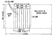
제 4 도는 일 트랙의 재생시간 간격과 신호 소거 기록 시간 간격과의 관계를 도시한 타임챠트(time chart).4 is a time chart showing the relationship between the playback time interval of one track and the signal erasing recording time interval.
제 5 도는 트랙 점프 위치 부근을 확대하여 도시한 개략 평면도.5 is an enlarged schematic plan view of the vicinity of a track jump position.
제 6 도는 신호 인코딩에 대한 블럭도.6 is a block diagram for signal encoding.
제 7 도는 서브 코드 채널의 구성의 블럭도.7 is a block diagram of the configuration of a sub code channel.
제 8 도는 신호 기록 및 재생 시스템의 전형적인 회로를 도시하는 블럭도.8 is a block diagram showing a typical circuit of a signal recording and reproducing system.
제 9 도는 소거 및 기록 신호용 파형도.9 is a waveform diagram of erase and write signals.
* 도면의 주요부분에 대한 부호의 설명* Explanation of symbols for main parts of the drawings
12 : A/D 변환기 13 : ECC 회로12: A / D converter 13: ECC circuit
14 : 변조기 16 : 버퍼 메모리14
17 : 펄스 발진기 18 : 1/2 분주기17: pulse oscillator 18: 1/2 divider
19 : 레이저원 구동회로 24 : 전자석 구동회로19 laser
25 : 스핀들 모터 29 : 비교 일치 검출회로25: spindle motor 29: comparison coincidence detection circuit
30 : 시스템 제어기 32 : 복조기30
33 : ECC-1회로 34 : D/A 변환기33: ECC- 1 circuit 34: D / A converter
101 : 자기 기록매체 103 : 자기 코일101: magnetic recording medium 103: magnetic coil
본 발명은 광 자기 디스크상이나 이로부터 데이타를 기록하고 재생하는데 적합한 신호 기록 및 재생 장치에 관한 것으로, 특히 새로운 신호가 신호 재생에 필요한 시간 간격에 명확히 맞는 시간 간격에서 기록될 수 있는 장치에 관한 것이다.The present invention relates to a signal recording and reproducing apparatus suitable for recording and reproducing data on or from a magneto-optical disk, and more particularly, to a device in which a new signal can be recorded at a time interval that clearly fits the time interval required for signal reproduction.
일반적으로, 최근에 광 자기 기록 시스템은 소위 직접 판독 이후 기입 시스템(direct read after write : DRAW SYSTEM)과 같은 다른 광학 기록 시스템과는 달리 데이타 재기록이 상기 시스템에 맞도록 하는 것에 관심이 집중되고 있다. 무엇보다도, 미래의 상용화를 위하여 외부 컴퓨터 메모리처럼 광 자기 디스크와 아울러 이러한 시스템의 실제적 응용분야에 연구가 행해지고 있다.In general, in recent years, attention has been focused on making a data rewrite fit into the system, unlike other optical recording systems such as so-called direct read after write (DRAW SYSTEM) systems. Above all, research is being conducted on practical applications of such systems with magneto-optical disks, such as external computer memories, for future commercialization.
제 1 도에 도시된 종래의 광 자기 기록 시스템의 동작 원리는 기본적으로 다음과 같다. 무엇보다도 먼저, 아래 방향으로 지향된 균일한 자화 M은 제 1a 도에 도시된 자기 디스크와 같은 자기 기록 매체(101)내에서 행해진다. 그후 자화 M 방향과 반대로 약한 바이어스 자계(weak bias magnetic field) H가 도시되지 않은 자기 코일(103)이나 영구자석에 의해 제 1b 도에 도시된 바와 같이 외부로부터 인가된다. 상기 디스크는 조사된 디스크 부분의 온도를 국부적으로 상승시키기 위하여 디스크상에 기록되어질 데이타 신호에 따라 변조된 광 빔, 통상적으로 레이저 빔 LB(laser beam)에 의해 조사된다. 이는 조사된 디스크 부분의 자화방향이 바이어스 자계 H의 방향과 일치되도록 역으로 되게 하여 제 1c 도에 도시된 바와 같은 기록된 자화 M'가 남게 한다. 신호 재생 동안에는, 광과 자성간의 상호작용에 관한 자기회전 효과, 즉 파라데이 효과(the Faraday effect)가 적용되어, 레이저 빔이 자기 기록 매체(101)를 스위프할(sweep) 경우, 다른 방향의 자화 M 혹은 M'에 의해 레이저 빔의 편광(polarization plane)면의 다른 회전각이 기록된 데이타 신호를 광학적으로 판독하도록 감지된다.The operating principle of the conventional magneto-optical recording system shown in FIG. 1 is basically as follows. First of all, the uniform magnetization M directed in the downward direction is performed in the
이전에 기록된 자기 매체(101)상에 데이타 신호를 기록할시에, 자기 매체의 전체 표면 또는 재기록이 요구되는 매체 부분에 레이저 빔이 영구적으로 인가되어, 조사된 부분의 자화방향을 미리 설정된 일정한 방향으로 정렬시키는데, 이때, 외부로 가해진 바이어스 자계의 방향은 자화 M 방향과 일치된다. 이러한 방식으로, 역자화 M'가 원래의 자화 M 방향과 정렬되게 일정하게 재배열되며, 미리 기록된 데이타가 소거된다. 다음, 외부 자계 혹은 바이어스 자계의 방향은 상술한 기록 동작의 경우에서 같이 자화 M 방향과 역방향이 되며, 헤드 유니트는 재기록될 데이타 신호에 따라 변조된 레이저 빔이 자기 매체상에 조사될 때 자기 매체를 스위프한다.When recording a data signal on a previously recorded
상술한 바와 같은 광 자기 기록 시스템에 있어서, 첫째로 디스크 양단에 걸린 자계로 디스크상의 구데이타를 소거하여, 역방향 자계로 새로운 데이타를 기입하는 것이 필수적이다. 이 때문에 자기 테이프 혹은 자기 디스크의 경우와 대조적으로 자기적 소거 및 기록 동작이 동시에 수행되지 않는 불편이 수반된다. 따라서, 새로운 데이타를 기입할시에, 기록에 사용된 시간과 동일한 시간이 소거하는데 소비되므로, 기록 시간은 재생 시간의 2배에 달하게 된다.In the magneto-optical recording system as described above, it is essential to first erase old data on the disc with a magnetic field across the disc and write new data in the reverse magnetic field. This entails the inconvenience that the magnetic erase and write operations are not performed at the same time as in the case of the magnetic tape or the magnetic disk. Therefore, when writing new data, the same time as the time used for recording is consumed for erasing, so that the recording time reaches twice the reproduction time.
그러므로, 기록되어질 데이타가 음악원과 같은 연속적인 신호라야 한다면, 이들 신호의 실시간 기록이 잘맞지 않아 기록의 기회를 잃게 되는바, 종래의 기록 및 재생 시스템과 비교할때 단점이 있게 된다.Therefore, if the data to be recorded is a continuous signal such as a music source, the real-time recording of these signals is not well-suited and the chance of recording is lost, which is a disadvantage compared with conventional recording and reproducing systems.
본 발명은 상기 단점을 해소하도록 설계되며, 소거 및 기록이 신호 재생 시간 간격에 맞는 시간 간격내에서 수행될 수 있는 광 자기 디스크 소거 및 기록 시스템을 제공하도록 안출되었다.The present invention is designed to solve the above drawbacks, and is intended to provide a magneto-optical disk erasing and recording system in which erasing and recording can be performed within a time interval corresponding to a signal reproduction time interval.
본 발명은 정보 신호 혹은 데이타가 기록되는 다수의 동심 기록 트랙을 가진 광 자기 디스크, 상기 디스크상에 신호를 기록하고 디스크에서 기록된 신호를 재생하기 위한 헤드 유니트, 상기 헤드 유니트에 기록신호 혹은 소거 신호를 공급하기 위한 기록 수단, 상기 헤드 유니트에 의해 판독된 신호를 재생하기 위한 재생 수단 및 소정의 동심 트랙을 재생하는데 필요한 시간 간격내에서 상기 헤드 유니트가 상기 디스크상에 상기 소정의 동심 트랙을 연속적으로 스위프하도록 하게끔 동작하는 제어 수단을 포함하는 광 자기 디스크와 사용하기 위한 신호 기록 및 재생 장치를 제공하는데, 상기 제어 수단은 상기 헤드 유니트가 제 1 스위핑시간(sweeping)과 제 2 스위핑 시간 사이에서 스위치되게 동작하여 상기 기록 수단이 상기 제 1 스위핑 시간 동안 소거 신호를 상기 헤드 유니트에 공급하고, 상기 제 2 스위핑 시간동안 상기 헤드 유니트에 시간축 압축(time-axis-compressed) 기록 신호를 공급한다.The present invention provides a magneto-optical disk having a plurality of concentric recording tracks on which information signals or data are recorded, a head unit for recording signals on the disk and reproducing the signals recorded on the disk, and recording or erasing signals on the head unit. Recording means for supplying a digital signal, reproducing means for reproducing the signal read by the head unit, and the head unit continuously and continuously the predetermined concentric tracks on the disc within a time interval necessary for reproducing a predetermined concentric track. A signal recording and reproducing apparatus for use with a magneto-optical disk comprising control means operable to sweep, wherein the control means causes the head unit to be switched between a first sweeping time and a second sweeping time. Operate so that the recording means erases during the first sweeping time. Supplying a call to the head unit, and the second sweep time supply the time-base compression (time-axis-compressed) signals to the recording head unit for.
상기 기록 및 재생 장치에 따라서, 동일 동심 기록 트랙상의 신호 소거 및 기록이 한 트랙의 재생 시간 간격을 갖는 시간 간격에서 성취될 수 있으며, 신호 기록이 이전에 기록된 트랙 영역상의 이전의 기록의 종료점에서 개시될 수 있는데, 다음과 같은 방식으로 된다. 신호 재기록, 즉, 새로운 데이타의 신호 소거 및 기록은 재생 시간 간격에 맞는 시간 간격내에서 이루어지는 반면, 기록된 신호의 연속성이 증가된다.Depending on the recording and reproducing apparatus, signal erasing and recording on the same concentric recording track can be achieved at a time interval having a reproduction time interval of one track, and at the end of the previous recording on the track area where the signal recording was previously recorded. It may be disclosed in the following manner. Signal rewriting, i.e., signal erasing and writing of new data, takes place within a time interval corresponding to the reproduction time interval, while continuity of the recorded signal is increased.
따라서, 신호 기록 및 재생 장치에 따라서, 상기 트랙 재생 시간에 적어도 2배인 시간 간격으로 종래의 장치와 사용할 수 있는 소정의 트랙상의 신호 재기록이 실시간에 따라 그리고 상기 트랙 재생 시간에 맞는 시간내에서 이루어질 수 있다. 또한 신호가 각각의 트랙상의 새로운 데이타의 교번적 소거 및 기록으로 재기록되므로써, 기록 트랙의 단부가 신호 연속성을 개선시키기 위하여 정확하게 접속될 수 있다.Thus, depending on the signal recording and reproducing apparatus, signal rewriting on a predetermined track that can be used with the conventional apparatus at a time interval that is at least twice the track reproducing time can be performed in real time and within a time corresponding to the track reproducing time. have. Also, since the signal is rewritten with alternating erasing and writing of new data on each track, the ends of the recording tracks can be connected correctly to improve signal continuity.
제 2 도는 본 발명을 실현하는 광 자기 디스크와 관련한 자기 기록 및 재생 장치의 기본 동작을 이해하는데 유용한 도면이다. 이 도면에서, 제 3 도에 도시된 디스크(1)상의 트랙 점프 위치 근처의 부분이 확대되어 도시된다.2 is a diagram useful in understanding the basic operation of the magnetic recording and reproducing apparatus in connection with the magneto-optical disk which realizes the present invention. In this figure, the portion near the track jump position on the
제 3 도에 의하면, 긴 연속 트랙(long continuous track ; 2)이 나선형 혹은 회선으로 즉, 광 자기 디스크(1)의 내측에서 외측으로 형성되어 있으며, 대략 360°의 각도에 상응하는 짧은 트랙 부분을 이하 간단하게 "트랙" 또는 "트랙 부분"이라 한다. 디스크(1)의 회전은 소거-기록 모드 동작동안 디스크의 선형 속도가 재생 모드 동작 동안의 선형 속도에 적어도 2배인 방식으로 제어된다. 이러한 방식에 있어서, 동일 트랙은 신호 재생 시간과 같은 시간 동안 2배로 스위프된다. 제 1 스위핑 시간은 소거에 할당되고 기록 스위핑 시간은 기록에 할당되어, 신호의 재기록 즉, 새로운 데이타의 소거 및 기록이 재생 시간과 명백히 동일한 시간내에 이루어질 수 있게 된다. 신호 재생 기간 동안 소정의 트랙에 대한 디스크의 회전수는 N이다. 트랙에 대한 판독 시간은 제 4 도에의 A에서 도시된 바와 같이 1/N 초이다. 동일 트랙에 대한 소거 및 기록을 위하여, 디스크 회전은 2N으로 증가되고, 제 4 도의 B에서 도시된 바와 같이 1/2N 초가 소거에 할당되는 반면 다음 1/2N 초가 기록에 할당되어, 소거 및 기록이 1/N 초의 시간 간격내에서 완료된다. 기록될 데이타 신호는 시간축을 따라서 1/2로 압축될 필요가 있음을 주지해야 한다.According to FIG. 3, a long
재기록을 위해 소거 및 기록 기간의 2배 기간동안 디스크(1)에서 동일 트랙 부분을 스위핑하기 위하여, 제 3 도의 트랙 부분(2a)은 예를 들면 우선 소거 모드 동작 기간동안 스위핑된다. 그때 J1에서 헤드 유니트는 1트랙을 뛰어넘음으로써 트랙(2a)으로 되돌아가고, 이 트랙(2a)는 또다시 기록모드로 스위핑된다. 다음 회전 즉, 제 3 회전 기간동안 다음 트랙(2b)은 트랙을 뛰어넘지 않고서 스위핑된다. 트랙(2b) 스위핑을 위해 완전히 1회전한 후, 헤드 유니트는 1트랙을 건너뜀으로서, 점 J2에서 트랙 2b로 복귀된다. 이러한 방식으로 트랙을 건너뜀으로써, 동일 트랙을 2회 스위핑하기 위해 제 2 회전이 매회 발생하게 된다. 이러한 방식으로, 모든 트랙 부분 또는 희망한 트랙 부분이 재기록을 위해 즉, 새로운 데이타의 소거 및 기록을 위해, 외주방향(outer periphery)으로 순차적으로 스위핑된다.In order to sweep the same track portion on the
제 2 도에는 소거 기록 모드동안 트랙 점프 위치의 주변에 대한 확대도가 도시된다. 이 도면에서 트랙 n-1, 트랙 n 및 트랙 n+1은 내부방향에서 외주방향으로 순차적으로 도시되며, 그 동작은 i로 표시된 단계에서 Vi로 도시된 단계로 순차적을 진행된다. 참조부호 i 내지 Vi는 소거 모드에 대해 2점 쇄선으로, 재생 또는 판독 모드에 대해 복선(double line)으로, 기록 즉 기입 모드에 대해 굵은 실선으로 도시되어 있는 레이저 빔 통로 즉, 궤도를 표시한다. 한 트랙 n 내에서 얼마간의 빔 궤도 즉, 통로가 제 2 도에서 분리되도록 도시되어 있지만, 결과적으로 이러한 빔 통로는 다른 통로상에서 한 통로가 중복되어 있는 것이다.2 is an enlarged view of the periphery of the track jump position during the erase recording mode. In this figure, track n-1, track n and track n + 1 are shown sequentially from the inner direction to the circumferential direction, and the operation proceeds sequentially from the step indicated by i to the step shown by Vi. Reference numerals i to Vi denote laser beam paths, i.e., orbitals, which are shown by a dashed-dotted line for the erase mode, a double line for the read or read mode, and a thick solid line for the write or write mode. Although some beam trajectories within one track n, i.e. the passages, are shown to be separated in FIG. 2, the result is that these beam passages overlap one passage on the other.
제 2 도에서, 트랙 n 상의 점 P1에서 빔 통로 i의 소거 모드를 완료하자마자 시간 τj동안 점 P1에서 다음 내부 트랙 n-1상의 점 P2로 트랙 점프가 발생한다. 이점 P2에서부터 빔 통로 ii에서 신호가 재생된다. 재생 신호의 상태에 따라서, 빔 통로 iii의 도움으로, 예를 들면 시간 간격 τr이 지난 후 점 P3에서 기록 모드 동작이 시작된다. 이와 같이 기록 모드 동작 동안, 위에서 설명된 바와 같이 시간축을 따라서 1/2로 압축된 신호는 데이타가 빔 통로 i에 의해 소거된 약 1트랙 길이만큼 기록된다. 기록 모드는 점 P1의 전방으로 트랙 n의 점 P4에서 완료된다. 기록 종료점 P4를 나타내는 어드레스 정보 또는 데이타는 앞으로 설명되는 바와 같이 이 시간에서 기록 종료점 바와 앞 부분에 기록된다. 점 P4에서부터 시간 간격 tc가 경과한 후 점 PS에서 빔 통로 iV에서 소거 모드가 시작되어, 약 1트랙 길이의 소거가 일어난다. 신호의 소거는 트랙 n+1의 점 P6에서 완료된다. 이점 P6에서부터 시간 τj내에서 트랙 점프가 발생하여, 헤드 유니트는 트랙 n상에서 기록이 이루어졌던 빔 통로 iii의 범위내에서 점 P7로 복귀된다. 신호는 이 점 P7에서부터 빔 V에 의해 이 빔 통로를 따라 재생되어, 기록 모드 동작의 끝 부분까지 빔 통로 iii에 기록된 어드레스 데이타를 재생하게 된다. 기록 종료점 P4는 이러한 어드레스 데이타에 의해 검출되어, 이 빔 통로 Vi에 의한 기록 모드 동작이 이 점 P4에서 시작될 수 있다.In FIG. 2, and in that as soon as P 1 during the time τj complete erasing mode of the beam passage i, the following inner tracks n-1 to point P 2 on the track jump occurs at the point P 1 on the track n. From P 2 the signal is reproduced in the beam path ii. Depending on the state of the reproduction signal, with the aid of the beam path iii, the recording mode operation is started at point P 3 , for example after a time interval tau r. In this manner during the recording mode operation, a signal compressed in half along the time axis as described above is recorded by about one track length in which data is erased by the beam path i. The recording mode is completed at point P 4 of track n in front of point P 1 . The address information or data indicating the recording end point P 4 is recorded at this time to the recording end bar and the front part as described later. After the time interval t c has elapsed from the point P 4 , the erase mode is started in the beam path iV at the point P S , so that an erase of about 1 track length occurs. The erasure of the signal is completed at point P 6 of
한 모드에서 다른 모드로의 스위칭 타이밍 즉, 통신 타이밍은 제 2 도의 점선으로 둘러싸인 트랙 점프 위치의 근방을 확대한 제 5 도를 참고로 하여 앞으로 설명된다.The timing of switching from one mode to another, i.e., the communication timing, is explained in the future with reference to FIG. 5, which enlarges the vicinity of the track jump position surrounded by the dashed line in FIG.
트랙상에 기록될 데이타 뿐만 아니라, 기록 종료점을 특정하는 어드레스 데이타 또는 정보 또한 기록 종료점 P4전방으로 제 5 도의 빔 통로 iii에 의해 소정의 자기 기록의 종료 영역상에 기록된다.In addition to the data to be recorded on the track, address data or information specifying the recording end point is also recorded on the end region of the predetermined magnetic recording by the beam passage iii of FIG. 5 in front of the recording end point P 4 .
이러한 어드레스 데이타로서 가령 숫자 1 내지 6을 이용할 경우, 기록 종료점 P4를 향하여 1에서 6으로 증가된 어드레스 데이타가 기록되어, 숫자 6을 기록하므로써 기록이 완료된다. 트랙 점핑후 재생 기간동안, 이러한 어드레스 신호는 순차적으로 판독되어, 숫자 6을 검출하므로써 기록 종료점 P4가 검출된다. 이때 모드는 기록 모드로 스위칭되어, 신호 인터럽트와 무관하게 연속적인 기록을 하게 한다.When
[어드레스 데이타 기록에 대한 실시예]EXAMPLES FOR ADDRESS DATA RECORDING
기록은 광학 디지탈 오디오 디스크의 일정인 콤팩트 디스크로 신호 변환도(signal convertibility)를 유지하는 방식으로 광 자기 디스크(1)상에서 실행된다. 제 6 도는 신호 기록의 한 실시예를 도시한 것이다. 오디오 신호는 A/D 변환기에 의해 매 샘플당 16비트의 속도로 디지탈 신호로 변환된다. 각각의 샘플은 동일한 2부분으로 나누어지고, 각 부분은 1유니트 또는 심볼이다. 각각 4심볼의 P 및 Q 착오 정정 패리티 코드와 제어 또는 사용자 비트가 12워드 즉, 24심볼의 정보 즉, 데이타가 부가되어, 33심볼 즉 264데이타 비트로 구성된 완전한 처리 유니트(a complete processing unit) 즉, 프레임을 이루게 된다. 1-프레임 데이타 비트를 디스크에 기록하기 위하여, 이 데이타 비트는 각기 8비트 데이타의 심볼을 14비트 패턴으로 변환시키는 소위 8/14(eight-to-fourteen modulation) 변조 즉 EFM 처리를 받는다. 24-비트 동기 패턴이 각 프레임 선단부에 부가된다. 상기 패턴 사이는 3접속 비트에 의해 접속되어 한 프레임의 기록 패턴이 전체 586 채널 비트에 의해 형성된다.Recording is performed on the magneto-
제 6 도에 도시된 8제어 비트 즉, 사용자 비트 또는 98프레임에 대응한 98심볼은, 8서브-코드 채널, P, Q, R, S, T, U, V 및 W를 만드는 각 8비트 심볼의 8비트와 함께 제 7 도에 도시된 블럭에 수집된다. 블럭 경계를 정하기 위하여, 블럭 동기 패턴 S0, S1이 각 블럭의 2선두(leading-end) 심볼에 추가된다. 이들 동기 패턴 S0, S1을 기록하는 시간에서의 14비트 패턴은 EFM에 사용되는 것과 다른 룰(rule)을 벗어난 패턴이다.The eight control bits shown in FIG. 6, i.e., 98 symbols corresponding to user bits or 98 frames, each 8-bit symbol that makes up the 8 sub-code channels, P, Q, R, S, T, U, V and W. Are collected in the block shown in FIG. To define block boundaries, block sync patterns S 0 , S 1 are added to the leading-end symbols of each block. The 14-bit pattern at the time of recording these sync patterns S 0 , S 1 is a pattern out of rules different from those used for EFM.
상술한 바와 같은 기록 포맷을 가지고 종점 지정을 기록하는 어드레스 데이타는 1프레임내의 서브-코딩 부분을 사용하여 표시되는데, 상기 부분은 제 6 도의 데이타 비트 포맷에서 사용자용 비트 부분 또는 제 6 도의 채널 비트 포맷에서 프레임 동기 패턴 다음의 14비트이다. 프레임 동기 패턴이 사용될 때, 복수의 룰을 벗어난 패턴 즉, EFM 변환표에 포함되어 있지 않은 패턴중 상기 동기 패턴 S0및 S1을 제외한 패턴을 6개 선출하여 이들에 차례로 상기 어드레스 데이타로 되는 숫자, 예를 들면 "1" 내지 "6"을 순차적으로 다음 시키는 것이 좋다. 사용자용 비트를 사용하는 경우에는, 상기 서브 코드 채널의 R 내지 W에 대응하는 6비트 가운데 몇비트(예컨대 3비트)를 선택해 이들 비트에 의해 상기 어드레스 정보로 되는 숫자 "1" 내지 "6"을 표시하면 된다.Address data for recording the end point designations with the recording format as described above is represented using a sub-coding portion in one frame, which is the user bit portion or the channel bit format of FIG. 6 in the data bit format of FIG. Is 14 bits after the frame sync pattern. When a frame sync pattern is used, a number out of a plurality of rules, that is, a pattern not included in the EFM conversion table, is selected from six patterns except for the sync patterns S 0 and S 1 , and the numbers become the address data in this order. For example, "1" to "6" may be next sequentially. In the case of using the user bits, a few bits (for example, three bits) are selected from the six bits corresponding to R to W of the sub code channel, and the numbers "1" to "6" which become the address information by these bits are selected. You can display it.
이들 어드레스 데이타는 기록 종료점 P4의 바로 앞부분의 예를 들면 6프레임의 서브-코딩 부분에, 예를들면 진행 방향으로 "1" 내지 "6"의 순서로 기록된다. 제 6 도의 서브-코딩 부분이 어드레스 데이타 "1"내지 "6"에 의해 순차적으로 대체되는 6-프레임 데이타 신호의 기록후에 기록 모드가 완료된다. 블럭 동기 패턴 S0, S1가 이들 6프레임의 서브-코딩 부분에 포함되면, 이 패턴 S0, S1이 우선적으로 사용되어, 제 7 도에 도시된 블럭의 2개의 선두 프레임에 제 2 및 제 3 프레임이 대응할 때, 어드레스 데이타 "2" 및 "3"을 표시해야 하는 서브-코딩 부분이 블럭 동기 패턴 S0, S1에 의해 대체된 후에 상기 서브-코딩 부분이 기록된다. 따라서, 서브-코딩 부분 "1", S0, S1, "4", "5", "6"이 기록된다.These address data are recorded in the sub-coding portion of, for example, six frames immediately before the recording end point P 4 , for example in the order of "1" to "6" in the advancing direction. The recording mode is completed after the recording of the six-frame data signal in which the sub-coding portion of FIG. 6 is replaced by the address data " 1 " If the block sync patterns S 0 and S 1 are included in the sub-coding portion of these six frames, these patterns S 0 and S 1 are used first, so that the second and second frames in the two leading frames of the block shown in FIG. When the third frame corresponds, the sub-coding part is recorded after the sub-coding part which should represent the address data "2" and "3" is replaced by the block sync patterns S 0 , S 1 . Thus, the sub-coding portions "1", S 0 , S 1 , "4", "5", "6" are recorded.
[회로 구조의 실시예][Example of Circuit Structure]
상기 동작 순서의 실현을 위한 실제 회로를 제 8 도를 참조하여 설명한다.An actual circuit for realizing the above operation sequence will be described with reference to FIG.
여기에서, 오디오 신호와 같은 정보 신호는 입력 단자(11)에 공급된다. 이 입력 신호는 A/D 변환기(12), ECC 회로 즉 착오 정정 코드 생성 및 부가 회로(13), 8/14 변조기(14)를 포함하는 디지탈 처리회로(15)에 공급된다. 이 회로(15)는 초당 4.32M 비트의 비트율 f로서 제 6 도의 채널 비트 신호와 같은 1프레임당 588비트의 디지탈 신호를 출력시킨다. 이 디지탈 신호는 시간축 압축을 위한 버퍼 메모리(16)에 공급되어 비트율![]()
![]()
![]()
![]()
이러한 상태는 제 9 도의 파형도에 도시되는데 여기서 (A)는 버퍼 메모리(16)내에서 디지탈 처리회로(5)로부터 판독된 블럭 데이타 B1, B2, B3에.....를 표시하며, (B)는 1/2시간축 압축후에 버퍼 메모리로서 판독된 동일 블럭 데이타 B1, B2, B3...... 및 일정 소거 레벨을 가지는 소거 신호 EL을 표시하며, (C)는 전자석 구동회로에 공급된 자화 반전 신호를 가리킨다.This state is shown in the waveform diagram of FIG. 9, where (A) indicates the block data B 1 , B 2 , B 3 read from the
따라서, 주파수![]()
![]()
![]()
![]()
![]()
![]()
시간축 압축되고, 버퍼 메모리(16)로부터 판독된 디지탈 신호는 광학 기록 및 재생을 위한 광학 헤드 유니트(20)의 레이저 다이오드(21)와 같은 레이저원(laser source)을 구동시키도록 설계된 레이저원 구동회로(19)에 공급된다. 이 레이저 다이오드(21)로부터의 레이저 빔은 도시되지 않은 렌즈와 같은 광학 시스템을 통하여 광-자기 디스크(1)의 기록 표면상에서 조사된다. 헤드 유니트(20)는 포토 다이오드(22)와 같은 수광소자(receiving element)를 포함한다. 상술한 바와 같이, 광-자기 디스크(1)상의 기록 및/또는 소거에 필요한 바이어스 자계를 발생시키기 위하여, 전자석(23)이 디스크(1)에 근접하여 설치된다. 자석(23)은 구동회로(24)에 의해 여자되어, 자극이 기록 및 소거의 전환 시간에 바뀌는 방식으로 제어된다. 디스크(1)는 스핀들 모터(25)에 의해 회전 구동된다.The digital signal, which is time-base compressed and read out from the
상기 광학적 헤드 유니트(20)는 디스크(1)의 트랙을 추적할 때 소거-기록을 위하여 레이저 빔을 조사하며, 기록된 신호를 판독하도록 포토 다이오드(22)와 같은 수광소자에 의해 디스크(1)로부터 반사된 빛을 검출한다.The
시스템 제어기(30)는 상술한 기록 재생 장치의 전체적인 기능을 제어한다. 따라서 이 제어기는 디지탈 처리회로(15)에서의 기록 디지탈 선호 형성, 버퍼 메모리(16)에서의 판독/기록 동작, 레이저 구동회로(19)에서의 레이저 방사 구동 동작, 전자석 구동회로(24)에서의 자석 여자 및 스핀들 모터(25)의 회전을 제어한다. 상술한 어드레스 정보 또는 데이타를 기록할 때, 어드레스 데이타 "1" 내지 "6"을 표시하는 채널 비트패턴이 이미 기억된 ROM으로부터 판독된 비트 패턴 데이타가 기록 종단부의 근처에서 6개 프레임의 서브코딩부를 치환하여 버퍼 메모리(16)내에 기록되는 방식으로 제어동작이 수행된다. 버퍼 메모리(16)로의 기록은 통상적으로 실행되며 ROM으로부터 공급된 어드레스 데이타 비트 신호는 데이타 판독 시간에 출력 디지탈 신호의 대응 프레임의 서브 코딩부를 대신하여 레이저 구동회로(19)에 공급되어진다. 그러나 이 경우에 있어서, 버퍼 메모리(16)로부터 나온 데이타와 유사하게, ROM으로부터 나온 어드레스 데이타 비트 패턴은 통상의 2배의 주파수![]()
![]()
신호 재생 회로는 상기 헤드 유니트(20)의 수광소자인 포토 다이오드(22)로부터 판독된 신호를 복조하는 복조기(32)와, 복조된 디지탈 신호에서의 패리티 워드(parit word)에 근거하여 착오 정정을 실행하는 착오 정정 디코드 회로(33)(ECC-1회로)와, D/A 변환기(34)를 포함하는 재생 데이타 처리회로(25)를 구비한다. 상기 처리회로(35)의 D/A 변환기(34)로부터 나온 오디오 신호와 같은 아나로그 출력 신호는 출력 단자(36)에서 취해진다.The signal regeneration circuit demodulates an error based on a
상술한 소거 및 기록 모드의 트랙 점프 바로 후의 재생 동안, 포토 다이오드(22)로부터 나온 판독 신호는 비교 일치 검출회로(29)에 공급되는데 각각의 프레임 서브 코딩부의 신호 패턴이 상술한 어드레스 데이타 "1" 내지 "6" 검출용 버퍼 메모리(16)의 어드레스 데이타 패턴과 비교된다. 검출된 출력 신호는 시스템 제어기(30)에 공급된다. 시스템 제어기에서 상기 판독 및 검출된 어드레스 정보가 "1"에서 "6"으로 변화하는 것을 판단하고, 상기 기록의 종료점이 어딘가를 판별하여, 이 기록 종료점에서 다음의 기록 동작을 개시하도록 버퍼 메모리(16)의 판독 동작이나 레이저 구동기(19)의 구동 동작등이 제어된다. 종단부 근처의 6프레임의 각 어드레스 데이타중의 일부가 결락(drop out)되어 있는 경우, 예컨대 상기 블럭 동기 S0, S1으로 치환되어 있거나, 매체의 결함이나 기록 재생의 오동작등에 의해 신호가 판독되지 않는 경우 등에는, 시스템 제어기(30) 내부에서의 처리에 의해 결락부의 전후의 어드레스 정보에 의거하여 기록 종료점을 예측하고, 이 예측된 종료점으로부터 다음의 기록 동작을 개시시키면 된다. 트랙 점프(예를 들면, 제 2 도에서 점 P6)의 시작은 디스크 회전용으로 사용된 스핀들 모터(25)의 회전 상태를 판별함으로써 시스템 제어기(30)에 의해 판단될 수 있다.During the reproduction immediately after the track jump in the erase and write mode described above, the read signal from the
종단점에 대해서, 시스템 제어기(30)는 제 2 도에서의 점 P7과 같은 트랙 점프의 종단점이 전회 기록된 트랙의 기록 종료 부근에서 6개의 어드레스 데이타 프레임의 범위내에 위치될 수 있는 방식으로 트랙 점프를 제어할 필요가 있다. 예를 들어, 재생용 트랙을 스위핑하는 빔 통로 V에 따라 어드레스 데이타의 확실한(positive) 판별에 필요한 시간이 τr이라 하고 가정 트랙 점프 동작시간을 Ti라 한다. 전회 기록의 종료점 P4의 타이밍, 현재 트랙의 스위핑을 완료하는데 필요한 시간 및 상기 주기 τr 및 τj에 따라 점 P4에 도달하는 시간전의 시간(τr+τj)에서 트랙 점핑을 시작하기 위해서 시스템 제어기(30)는 제어를 행할 필요가 있다.For the end point, the
트랙 점핑의 종료 바로 이후의 어드레스 데이타는 처리회로(35)의 복조로부터의 출력과 ECC-1회로(33)로부터의 출력을 기초로 결정될 수 있다.The address data immediately after the end of the track jumping can be determined based on the output from the demodulation of the processing circuit 35 and the output from the ECC- 1
정상 재생 모드 동작동안, 디스크(1)의 회전 속도는 소정의 정상 선속도에 맞도록 제어되며, 재생 신호는 처리회로(35)에 의해 얻어진다.During the normal playback mode operation, the rotational speed of the
이러한 식으로, 신호 소거 및 시간축 압축된 신호의 기록이 정상 신호 재생 시간 간격인 시간 간격내에서 완료될 수 있으므로, 신호 재생 시간 간격에 맞는 시간 간격내에서 명백하게 실시간 기록을 할 수 있게 된다. 무엇보다도, 오디오 신호와 같은 연속 신호는 쉽게 기록된다. 각 트랙상에 시간축 압축된 신호의 기록에 관하여는, 전회 기록된 영역의 종단부 근처의 어드레스 데이타가 판독되고, 시스템 제어기의 동작하에 다음 기록이 상기 전회 기록 종료점에서 개시되어, 기록 신호의 고정도의 접속이 행해지며, 신호 연속성이 높아진다.In this way, the signal cancellation and the recording of the time base compressed signal can be completed within the time interval that is the normal signal reproduction time interval, so that it is possible to clearly record in real time within the time interval corresponding to the signal reproduction time interval. First of all, continuous signals such as audio signals are easily recorded. Regarding the recording of the time-base compressed signal on each track, address data near the end of the last recorded area is read out, and under the operation of the system controller, the next recording is started at the last recording end point, so that the high accuracy of the recording signal is achieved. The connection is made and signal continuity is increased.
본 발명은 상술한 특정 실시예에만 국한되지 않고 다수의 수정이 가능하다. 예를 들어 기록하려는 신호로서 오디오 신호뿐만 아니라 일반의 컴퓨터 데이타 신호와, 비디오 신호가 포함된다. 소거 및 기록 모드시의 자기 디스크의 회전속도는 재생시의 2배로 하고 있으나, 이외 3배 혹은 4배가 될 수 있다. 그러나, n배의 속도로 신호 소거를 하기 위해서는![]()
![]()
Claims (7)
Applications Claiming Priority (4)
| Application Number | Priority Date | Filing Date | Title |
|---|---|---|---|
| JP60889 | 1985-03-27 | ||
| JP60060889A JPH079718B2 (en) | 1985-03-27 | 1985-03-27 | Optical-erasing / recording methods for magnetic disks |
| JP18788885A JPH0668852B2 (en) | 1985-08-27 | 1985-08-27 | Optical-magnetic disk recording / reproducing device |
| JP187888 | 1985-08-27 |
Publications (2)
| Publication Number | Publication Date |
|---|---|
| KR860007640A KR860007640A (en) | 1986-10-15 |
| KR940010949B1 true KR940010949B1 (en) | 1994-11-19 |
Family
ID=26401946
Family Applications (1)
| Application Number | Title | Priority Date | Filing Date |
|---|---|---|---|
| KR1019860002293A KR940010949B1 (en) | 1985-03-27 | 1986-03-27 | Singal recording & reproducing apparatus for opto-magnetic disk |
Country Status (5)
| Country | Link |
|---|---|
| US (1) | US4733385A (en) |
| EP (1) | EP0196590B1 (en) |
| KR (1) | KR940010949B1 (en) |
| CA (1) | CA1253249A (en) |
| DE (1) | DE3685358D1 (en) |
Families Citing this family (32)
| Publication number | Priority date | Publication date | Assignee | Title |
|---|---|---|---|---|
| JPS61276103A (en) * | 1985-05-31 | 1986-12-06 | Canon Inc | Recording system for photomagnetic memory |
| US4888750A (en) * | 1986-03-07 | 1989-12-19 | Kryder Mark H | Method and system for erase before write magneto-optic recording |
| JP2574765B2 (en) * | 1986-07-09 | 1997-01-22 | 株式会社日立製作所 | Magneto-optical disk device |
| EP0276326B1 (en) * | 1986-07-31 | 1994-09-07 | Sony Corporation | Optical disc recording/reproducing apparatus |
| US5293361A (en) * | 1986-10-08 | 1994-03-08 | Canon Kabushiki Kaisha | Information processing method and apparatus therefor in which an erasing device is driven for a period longer than a necessary period |
| JP2682621B2 (en) * | 1987-03-03 | 1997-11-26 | オリンパス光学工業株式会社 | Bias magnetic field abnormality detector |
| US4814903A (en) * | 1987-06-29 | 1989-03-21 | International Business Machines Corporation | Alternate storage areas in magnetooptical media |
| JPH01292651A (en) * | 1988-05-19 | 1989-11-24 | Olympus Optical Co Ltd | Bias magnetic field shifting device for magneto-optical recording device |
| US5034934A (en) * | 1988-07-15 | 1991-07-23 | Pioneer Electronic Corp. | Opto-magnetic disk unit with improved dynamic range characteristics and opto-magnetic disk therefor |
| JP2760812B2 (en) * | 1988-09-28 | 1998-06-04 | 株式会社日立製作所 | Optical reproducing apparatus and optical reproducing method |
| JP2850348B2 (en) * | 1989-02-14 | 1999-01-27 | ソニー株式会社 | Optical disk recording / reproducing method |
| US5148416A (en) * | 1989-06-05 | 1992-09-15 | Nikon Corporation | Signal processing circuit for magnetooptical record/reproducing apparatus |
| US5191563A (en) * | 1989-06-29 | 1993-03-02 | Digital Equipment Corporation | Method for increasing track density of magneto-optical storage media |
| US5212678A (en) * | 1989-11-23 | 1993-05-18 | U.S. Philips Corporation | System for recording and reading information on a record carrier at a constant scanning speed independent of the bit rate of such information |
| EP0635829B1 (en) * | 1990-01-19 | 1998-05-20 | Sony Corporation | Data recording apparatus |
| US5517477A (en) * | 1990-01-19 | 1996-05-14 | Sony Corporation | Data recording method and data reproducing apparatus |
| KR100195317B1 (en) * | 1990-01-19 | 1999-06-15 | 이데이 노부유끼 | Data recording and reproducing method |
| EP0465053B1 (en) * | 1990-06-29 | 2002-08-28 | Sony Corporation | Disc recording/reproducing apparatus |
| JP2881980B2 (en) * | 1990-06-29 | 1999-04-12 | ソニー株式会社 | Disk recording device and disk reproducing device |
| JP2733127B2 (en) * | 1990-08-07 | 1998-03-30 | シャープ株式会社 | Magneto-optical recording device |
| JP2995822B2 (en) * | 1990-08-23 | 1999-12-27 | ソニー株式会社 | Recording device and reproducing device for disk-shaped recording medium |
| JP3141241B2 (en) * | 1990-08-24 | 2001-03-05 | ソニー株式会社 | Disk recording device and disk reproducing device |
| JP3158474B2 (en) * | 1991-03-28 | 2001-04-23 | ソニー株式会社 | Recording method, disk recording device and disk reproducing device |
| US5630112A (en) * | 1991-06-19 | 1997-05-13 | Kabushiki Kaisha Toshiba | System using timing information contained in data read from reproduction unit controlled by first oscillator to vary frequency of independent system clock signal |
| JP3230319B2 (en) * | 1992-07-09 | 2001-11-19 | ソニー株式会社 | Sound reproduction device |
| JPH0778412A (en) * | 1993-07-13 | 1995-03-20 | Sony Corp | Device and method for recording/reproducing and device and method for reproducing |
| JP3591028B2 (en) * | 1995-01-25 | 2004-11-17 | ソニー株式会社 | Playback device and playback method |
| JP3557721B2 (en) * | 1995-05-11 | 2004-08-25 | ソニー株式会社 | Recording device |
| JPH1064244A (en) * | 1996-08-23 | 1998-03-06 | Sony Corp | Storage medium and reproducing device |
| GB2371918B (en) * | 1999-11-12 | 2003-11-26 | Seagate Technology Llc | Magnetic media patterning utilizing heat-induced phase transition |
| JP4183868B2 (en) * | 1999-12-07 | 2008-11-19 | 富士通株式会社 | Optical storage device |
| JP4086718B2 (en) * | 2003-06-10 | 2008-05-14 | キヤノン株式会社 | Information processing method and information processing apparatus |
Family Cites Families (8)
| Publication number | Priority date | Publication date | Assignee | Title |
|---|---|---|---|---|
| US3789137A (en) * | 1972-04-07 | 1974-01-29 | Westinghouse Electric Corp | Time compression of audio signals |
| JPS52102014A (en) * | 1976-02-24 | 1977-08-26 | Sony Corp | Signal processing apparatus |
| JPS5661078A (en) * | 1979-10-23 | 1981-05-26 | Toshiba Corp | Recording system for index information |
| JPS5792446A (en) * | 1980-11-26 | 1982-06-09 | Olympus Optical Co Ltd | Recording, reproduction and erasure system for information using photomagnetic recording medium |
| JPS57200960A (en) * | 1981-06-04 | 1982-12-09 | Pioneer Electronic Corp | Recording and reproducing method and its device |
| JPS5883347A (en) * | 1981-11-09 | 1983-05-19 | Canon Inc | Photomagnetic recording device |
| JPS59157811A (en) * | 1983-02-25 | 1984-09-07 | Nec Corp | Data interpolating circuit |
| JPS61216149A (en) * | 1985-03-20 | 1986-09-25 | Akai Electric Co Ltd | Information signal recording method for photomagnetic disk recording and reproducing device |
-
1986
- 1986-03-24 EP EP86104025A patent/EP0196590B1/en not_active Expired - Lifetime
- 1986-03-24 DE DE8686104025T patent/DE3685358D1/en not_active Expired - Lifetime
- 1986-03-26 CA CA000505129A patent/CA1253249A/en not_active Expired
- 1986-03-26 US US06/844,190 patent/US4733385A/en not_active Expired - Lifetime
- 1986-03-27 KR KR1019860002293A patent/KR940010949B1/en not_active IP Right Cessation
Also Published As
| Publication number | Publication date |
|---|---|
| EP0196590A2 (en) | 1986-10-08 |
| CA1253249A (en) | 1989-04-25 |
| DE3685358T (en) | 1992-06-25 |
| EP0196590B1 (en) | 1992-05-20 |
| DE3685358D1 (en) | 1992-06-25 |
| EP0196590A3 (en) | 1989-08-30 |
| KR860007640A (en) | 1986-10-15 |
| US4733385A (en) | 1988-03-22 |
Similar Documents
| Publication | Publication Date | Title |
|---|---|---|
| KR940010949B1 (en) | Singal recording & reproducing apparatus for opto-magnetic disk | |
| US5325347A (en) | Data recording method and data reproducing apparatus with contiguous data recording | |
| US5367510A (en) | Disk recording/reproducing apparatus having the capability of recording an operator designated program sequence | |
| US5058096A (en) | Disk recording/reproducing apparatus and disk recording/reproducing method | |
| US4853915A (en) | Optical recording/reproducing method and apparatus for optical disk medium having unique control parameters | |
| ES2259004T3 (en) | DISC PLAYER APPARATUS. | |
| KR100255345B1 (en) | Method of and apparatus for reproducing a recording medium | |
| RU2274909C2 (en) | Optical disc and device for optical disc | |
| JP4294318B2 (en) | Optical record carrier and recording / reproducing apparatus for record carrier | |
| KR100616047B1 (en) | Recording Apparatus and Method, and Reproducing Apparatus and Method | |
| JP2746873B2 (en) | Information processing device | |
| JPS63148421A (en) | Optical disk device | |
| JP3280397B2 (en) | Information recording / reproducing apparatus and recording / reproducing method | |
| JPH0668852B2 (en) | Optical-magnetic disk recording / reproducing device | |
| KR970011813B1 (en) | Method for recording and reproducing an optical disk | |
| JPS63148422A (en) | Optical disk device | |
| KR0134277B1 (en) | Recording & reproducing method of optical disk | |
| JPS63160065A (en) | Optical disk device | |
| JP3436257B2 (en) | Data recording method and data recording device, data reproducing method and data reproducing device | |
| JP2604288B2 (en) | Skip recording or playback circuit | |
| KR0134278B1 (en) | Recording & reproducing method of optical disk | |
| CA2242161C (en) | Optical disk, and information recording/reproduction apparatus | |
| JPH06150329A (en) | Optical disk and recording and reproducing device for optical disk | |
| JPH0816994B2 (en) | Disk recorder | |
| JPH083905B2 (en) | Laser diode automatic output control circuit |
Legal Events
| Date | Code | Title | Description |
|---|---|---|---|
| A201 | Request for examination | ||
| E902 | Notification of reason for refusal | ||
| G160 | Decision to publish patent application | ||
| E701 | Decision to grant or registration of patent right | ||
| GRNT | Written decision to grant | ||
| FPAY | Annual fee payment |
Payment date: 20051031 Year of fee payment: 12 |
|
| EXPY | Expiration of term |