KR840002376B1 - Electronic electric-energy meter - Google Patents
Electronic electric-energy meter Download PDFInfo
- Publication number
- KR840002376B1 KR840002376B1 KR1019810001648A KR810001648A KR840002376B1 KR 840002376 B1 KR840002376 B1 KR 840002376B1 KR 1019810001648 A KR1019810001648 A KR 1019810001648A KR 810001648 A KR810001648 A KR 810001648A KR 840002376 B1 KR840002376 B1 KR 840002376B1
- Authority
- KR
- South Korea
- Prior art keywords
- circuit
- pulse width
- time division
- voltage
- signal proportional
- Prior art date
Links
Images


Classifications
-
- G—PHYSICS
- G01—MEASURING; TESTING
- G01R—MEASURING ELECTRIC VARIABLES; MEASURING MAGNETIC VARIABLES
- G01R21/00—Arrangements for measuring electric power or power factor
- G01R21/127—Arrangements for measuring electric power or power factor by using pulse modulation
- G01R21/1271—Measuring real or reactive component, measuring apparent energy
-
- G—PHYSICS
- G01—MEASURING; TESTING
- G01R—MEASURING ELECTRIC VARIABLES; MEASURING MAGNETIC VARIABLES
- G01R21/00—Arrangements for measuring electric power or power factor
- G01R21/06—Arrangements for measuring electric power or power factor by measuring current and voltage
Landscapes
- Engineering & Computer Science (AREA)
- Power Engineering (AREA)
- Physics & Mathematics (AREA)
- General Physics & Mathematics (AREA)
- Measurement Of Current Or Voltage (AREA)
- Electric Clocks (AREA)
Abstract
Description
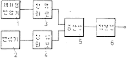
제1도는 종래의 피상 전력량계의 구성도.1 is a configuration diagram of a conventional apparent meter.
제2도는 본 발명의 원리를 설명하기 위한 전자식 전력량계의 구성도.2 is a block diagram of an electronic wattmeter for explaining the principle of the present invention.
제3도는 제2도의 펄스 폭 변조회로의 구성도.3 is a configuration diagram of the pulse width modulation circuit of FIG.
제4도는 펄스 폭 변조회로의 동작설명도.4 is an operation explanatory diagram of a pulse width modulation circuit.
제5도는 본 발명의 1실시예를 설명하기 위한 피상 전력파형도.5 is an apparent power waveform diagram for explaining an embodiment of the present invention.
제6도는 동 실시예에 의한 피상 전력량계의 구성도이다.6 is a configuration diagram of an apparent power meter according to the embodiment.
본 발명은 전자식 피상 전력량계에 관한 것이다. 피상 전력량을 측정할 경우에는 종래 2가지의 방식이 고려되고 있다. 그 하나는, 유효전력량계와 무효전력량계의 2개의 신호를 받아, 유효전력 P와 무효전력 Q에서![]()
![]()
이와 같은 2가지 방법이 일반적으로 알려져 있으나, 전자의 방법으로는 유효전력량계와 무효전력량계가 필요해지므로 시스템이 약간 커지는 결점이 있다. 또 후자는 정류회로의 특성(다이오드 등의 특성)이 그대로 피상 전력량계의 특성이 되기 때문에 고정밀도의 개량을 할 수 없는 결점이 있다.Two such methods are generally known, but the former method requires an active power meter and a reactive power meter so that the system becomes slightly larger. In the latter case, since the characteristics of the rectifier circuit (such as diodes) become the characteristics of the apparent power meter as it is, there is a drawback that high accuracy cannot be improved.
본 발명은 상기의 점을 고려하여 연구된 것으로서 간단한 구성으로 고정밀도의 피상 전력량의 측정을 가능하게 하는 전자식 피상 전력량계를 제공하는 것을 목적으로 한다.The present invention has been studied in view of the above point, and an object thereof is to provide an electronic apparent watt-hour meter that enables the measurement of a high-precision apparent power amount with a simple configuration.
이하 본 발명의 1실시예를 도면을 참조하면서 설명한다. 우선 본 발명의 1실시예를 설명하기 전에 본 발명에 관한 전자식 전력량계의 원리를 설명한다. 제2도는 전자식 전력량계의 일반적인 구성을 나타내는 것으로서, (10)은 전력급전선의 부하전압에 비례한 신호를 검출하는 계기용 변압기이다. (11)은 계기용 변압기(10)의 신호에 의하여 펄스 폭 변조하여 펄스 폭 충격계수(duty cycle)를 얻는 펄스 폭 변조회로이다. 한편, (12)는 전력급전선의 소비 전류에 비례한 신호를 검출하는 전류변압기이고 이 출력을 저항(13)에 의하여 전압신호로 변환하여 시분할 승산회로(14)에 인도한다. 이 시분할 승산회로(14)는 도시를 생략한 복수개의 아날로그스위치로 구성되고, 상기 펄스 폭 충격계수에 의하여 이들의 아날로그 스위치를 선택적으로 제어함으로써 소비전류에 비례하는 전압신호를 도입해서 시분할승산을 행하는 것이다. 그리고, 승산한 결과를 적분회로(15)로 적분하고, 전압출력을 얻어서 이것을 전압펄스 주파수 변환회로(16)로 펄스출력으로 변환하여 분주회로(17)를 지나서 표시회로(18)에서 표시하도록 하고 있다.Hereinafter, an embodiment of the present invention will be described with reference to the drawings. First, the principle of the electronic electricity meter according to the present invention will be described before explaining one embodiment of the present invention. 2 shows a general configuration of an electronic electricity meter, and
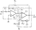
그러나 이와같이 구성된 전자식 전력량계의 펄스 폭 변조회로(11)는 실제로는 제3도와 같이 구성되어 있다. (A1)은 적분기를 구성하는 연산증폭기(OP 앰프)이고, (A2)는 적분출력을 받아 히스테리시스로 생기는 비교전압 eh와의 비교로 논리출력을 발생하는 비교기이다. 여기에서 상기 비교기(A2)의 출력은 논리 "1"일 때 +er, 논리 "0"일 때 -er의 진폭이 되도록 구성된다.However, the pulse width modulation circuit 11 of the electronic wattmeter thus constructed is actually configured as shown in FIG. (A 1 ) is an operational amplifier (OP amplifier) constituting an integrator, and (A 2 ) is a comparator which generates a logic output by comparing with the comparison voltage e h generated by hysteresis by receiving the integral output. Here, the output of the comparator A 2 is configured to be the amplitude of + e r when logic "1" and -e r when logic "0".
다음에 그 동작을 설명한다. 우선 er=0에 있어서 비교기(A2)의 출력이 논리 "1"로 정정(整定)되어 있다고 보면, 이 비교기(A2)의 부입력단자 전압 eh는 저항 R3,R4를 R3=R4로 하면 -er/2가 된다. 또 저항 R2을 거체서 +er인 전압이 적분기에 도입되어 있기 때문에 OP 앰프(A1)의 출력은 부방향의 적분경사를 나타내게 된다. 그리고, OP 앰프(A1)의 출력전압이 ek가 -er/2에 달하여 ek ![]()
![]()
![]()
![]()
이와같이 이 펄스 폭 변조회로는 자려진동을 반복한다. 이것을 제4도(a)~(c)에서 나타낸다. 동도면(a)는 비교기(A2)의 출력상태, 동 도면(b)는 비교기(A2)의 부입력 단자전압 eh, 동 도면(c)는 OP 앰프(A1)의 출력 ek를 각각 나타내는 것이다. 여기에서 비교기(A2)의 출력이 논리 "1"의 시간구간을 ta, 논리 "0"의 시간구간을 tb로 하면, 앰프출력 ek는In this manner, the pulse width modulation circuit repeats the vibration. This is shown in FIG. 4 (a)-(c). The same figure (a) shows the output state of the comparator A 2 , the figure (b) shows the negative input terminal voltage e h of the comparator A 2 , and the figure (c) shows the output e k of the op amp A 1 . Respectively. Here, when the output of the comparator A 2 sets the time interval of logic "1" to ta and the time interval of logic "0" to t b , the amplifier output e k is

여기에서 R1=R2로 하면Where R 1 = R 2

가 된다. 여기에서 펄스 폭 충격계수는Becomes Where the pulse width impact coefficient is

가 된다. 이것이 펄스 폭 변조회로의 원리이다.Becomes This is the principle of the pulse width modulation circuit.
상기한 바와 같은 전자식 전력량계의 원리를 기초로 하여 이하 본 발명의 1실시예를 설명한. 다우 선유효전력과 피상전력을 구하는 승산의 상태를 제5도를 사용하여 설명한다. 유효전력은 ev와 ei의 적(積)이고, 순간적으로 생각하면 t1의 시각에서는 A점과 B점의 승산이다. 또 피상전력은 ev를 ev와 ei의 위상차 분만 이상해서 승산하는 것으로서 본 발명은 상기의 설명과 같은펄스 폭 변조시분할승산 방식의 전력량계를 사용해서 t1의 시점에서 A점과 C점의 적을 구하는 것으로서 피상 전력량계를 구성하고 있다.Based on the principle of the electronic wattmeter as described above, one embodiment of the present invention is described below. The state of the multiplication for obtaining the Dow active power and the apparent power will be explained using FIG. The active power is the product of e v and e i , and in instantaneous terms, it is the multiplication of the A and B points at the time t 1 . Also apparent power e v a e v and as multiplying by more than the phase difference delivery of e i the present invention of using a pulse width modulation power meter of a time-division multiplying the same way as the above described point in time of t 1 A point and the C point The apparent wattmeter is constructed by finding the enemy.
제6도는 본 발명의 1실시예에 의한 전자식 피상 전력량계의 구성을 나타내는 것으로서 제2도와 동일 부분에는 동일 부호를 달아서 설명을 생략한다. 제6도에 있어서 (20)은 다만(多殷)의 랜덤 쉬프트레지스터로 구성된 지연회로, (21),(22)는 각각 교류신호를 펄스로 변환하는 펄스신호 변환회로, (23)은 상기 지연회로(20)에 대하여 펄스 폭 변조출력펄스를 공급하는 클럽 펄스 발생회로이다.6 shows the configuration of an electronic apparent power meter according to an embodiment of the present invention, in which the same parts as in FIG. In Fig. 6,
이와같은 구성에 있어서 펄스 폭 변조회로(11)의 출력은 제2도와 같이 즉시로 시분할 승산회로(14)에 도입하는 것이 아니고, 우선 지연회로(20)에 도입한다. 이 지연회로(20)은 상기한 바와 같이 다단의 랜덤 쉬프트레지스터로 구성되어 있고, 클럭 펄스 발생회로(23)으로부터의 펄스 폭 변조출력펄스를 도입하여, 차례로 쉬프트하면서 기억해서 지연시키도록 되어 있다. 펄스 변환회로(21),(22)로 교류신호가 펄스 신호로 변환되고, 이 변환된 펄스 신호를 상기 지연회로(20)에 보낸다. 이것으로 인해 현재의 위상차를 검출하여 지연회로(20)을 구성하는 랜덤 쉬프트레지스터의 입출력의 시점을 결정한다. 즉 전압신호 ev에 동기한 펄스의 수직상승부에서 전류신호 ei에 동기한 펄스가 수직상승할 때까지의 시간만 펄스 폭 변조출력 펄스를 유지한다. 이 펄스 폭 변조 출력펄스는 차례로 지연회로(20)를 구성하는 랜덤 쉬프트레지스터에 도입되어서 기억되는 동시에 쉬프트되어 펄스 변환회로(21),(22)에 의해서 만들어진 기간만 유지되고, 지연되어서 출력된다. 그리고 시분한 승산회로(14)에 도입되어서 승산이 실시된다. 즉 지연회로(20)에 의해서 항상 전압신호와 전류신호가 동위상이 되도록 승산이 실행되게 된다. 이 승산결과는 피상 전력을 나타나게 된다.In such a configuration, the output of the pulse width modulation circuit 11 is not immediately introduced into the time
이상 설명한 바와 같이 본 발명에 의하면 급전선의 부하전압에 비례한 전압신호를 펄스 폭 변조회로에 의하여 펄스 폭 충격계수로 변환하는 동시에 급전선의 소비전류에 비례한 신호를 전압변환부에 의하여 전압신호에 변환하여, 상기 펄스 폭 충격계수에 의하여 선택적으로 제어해서 상기 소비전류에 비례하는 전압신호를 시분할 승산회로에 받아들여 시분할 승산을 하는 전자식 전력량계에 있어서, 상기 펄스 폭 변조회로와 시분할 승산회로와의 사이에 지연회로를 설치하여, 상기 펄스 폭 충격계수를 상기 지연회로에 순차적으로 보내서 상기 부하 전압에 비례한 전압신호와 소비전류에 비례한 전압신호의 각각의 영점을 검출해서, 양자의 위상차분만 상기 펄스 폭 충격계수를 유지하여 지연시킨 후 상기 시분할 승산회로에서 시분할 승산을 실시해서 피상 전력을 얻도록 했기 때문에, 구성을 복잡하게 하는 일 없이 고정밀도의 피상 전력량의 측정이 가능한 전자식 피상 전력량계를 제공할 수 있다.As described above, according to the present invention, a voltage signal proportional to a load voltage of a feeder is converted into a pulse width shock coefficient by a pulse width modulation circuit, and a signal proportional to a current consumption of the feeder is converted into a voltage signal by a voltage converter. In the electronic watt-hour meter which is selectively controlled by the pulse width impact coefficient to receive a voltage signal proportional to the current consumption into a time division multiplication circuit and performs time division multiplication, between the pulse width modulation circuit and the time division multiplication circuit. A delay circuit is provided, and the pulse width impact coefficient is sequentially sent to the delay circuit so as to detect each zero point of the voltage signal proportional to the load voltage and the voltage signal proportional to the consumption current, so that only the phase difference between them is the pulse width. After holding and delaying the impact coefficient, time division multiplication is performed in the time division multiplication circuit. Since the apparent power is obtained, it is possible to provide an electronic apparent power meter that can measure a high-precision apparent power amount without complicating the configuration.
Claims (1)
Applications Claiming Priority (2)
| Application Number | Priority Date | Filing Date | Title |
|---|---|---|---|
| JP71723 | 1980-05-13 | ||
| JP7172380A JPS56168166A (en) | 1980-05-29 | 1980-05-29 | Electronic apparent watthour meter |
Publications (2)
| Publication Number | Publication Date |
|---|---|
| KR830006693A KR830006693A (en) | 1983-10-06 |
| KR840002376B1 true KR840002376B1 (en) | 1984-12-24 |
Family
ID=13468719
Family Applications (1)
| Application Number | Title | Priority Date | Filing Date |
|---|---|---|---|
| KR1019810001648A KR840002376B1 (en) | 1980-05-29 | 1981-05-13 | Electronic electric-energy meter |
Country Status (2)
| Country | Link |
|---|---|
| JP (1) | JPS56168166A (en) |
| KR (1) | KR840002376B1 (en) |
Families Citing this family (2)
| Publication number | Priority date | Publication date | Assignee | Title |
|---|---|---|---|---|
| JPS5935157A (en) * | 1982-08-24 | 1984-02-25 | Tokyo Electric Power Co Inc:The | Apparatus for measuring electric power |
| JPS6078357A (en) * | 1983-10-05 | 1985-05-04 | Tokyo Electric Power Co Inc:The | Watthour meter |
-
1980
- 1980-05-29 JP JP7172380A patent/JPS56168166A/en active Granted
-
1981
- 1981-05-13 KR KR1019810001648A patent/KR840002376B1/en active
Also Published As
| Publication number | Publication date |
|---|---|
| JPS6247255B2 (en) | 1987-10-07 |
| KR830006693A (en) | 1983-10-06 |
| JPS56168166A (en) | 1981-12-24 |
Similar Documents
| Publication | Publication Date | Title |
|---|---|---|
| US4463311A (en) | Electronic electric-energy meter | |
| US4066960A (en) | Electronic kilowatt-hour-meter with error correction | |
| EP0104999B1 (en) | Gain switching device with reduced error for watt meter | |
| US4291377A (en) | Apparatus for measuring electrical power | |
| KR840002376B1 (en) | Electronic electric-energy meter | |
| EP0058050A1 (en) | Measuring method | |
| JPS5819068B2 (en) | Denshiki Denryokuriyokei | |
| US5742156A (en) | Digital process for obtaining a measured parameter from an electric signal | |
| JP2000121679A (en) | Test method for electronic watthour meter and electronic watthour meter | |
| KR840002377B1 (en) | Electronic electric-energy meter | |
| JP3271323B2 (en) | Time measurement circuit | |
| JP3026533B2 (en) | Reactive energy meter | |
| JPH05333067A (en) | Electronic watt-hour meter | |
| US4066959A (en) | Electronic volt-square-hour metering method and apparatus | |
| SU661378A1 (en) | Digital power meter | |
| JPS5763459A (en) | Reactive power meter | |
| KR840002851Y1 (en) | Electronic electric-energy meter | |
| JPH11326428A (en) | Parameter measuring device for inverter circuit | |
| CA2003604A1 (en) | Electronic watt-hour meter with combined multiplier/integrator circuit | |
| SU1064207A1 (en) | Active electricity meter | |
| GB2227896A (en) | Analog-to-digital converter | |
| RU2053516C1 (en) | Kilowatt-hour meter | |
| JP3316121B2 (en) | Reactive energy meter | |
| RU2017161C1 (en) | Capacitance measurement device | |
| SU767663A1 (en) | Method for measuring phase shift |