KR20200030593A - Antigen presenting synthetic surfaces, covalently functionalized surfaces, activated T cells, and uses thereof - Google Patents
Antigen presenting synthetic surfaces, covalently functionalized surfaces, activated T cells, and uses thereof Download PDFInfo
- Publication number
- KR20200030593A KR20200030593A KR1020207005086A KR20207005086A KR20200030593A KR 20200030593 A KR20200030593 A KR 20200030593A KR 1020207005086 A KR1020207005086 A KR 1020207005086A KR 20207005086 A KR20207005086 A KR 20207005086A KR 20200030593 A KR20200030593 A KR 20200030593A
- Authority
- KR
- South Korea
- Prior art keywords
- cells
- activating
- antigen
- molecule
- antigen presenting
- Prior art date
Links
- 210000001744 T-lymphocyte Anatomy 0.000 title claims abstract description 449
- 239000000427 antigen Substances 0.000 title claims description 371
- 102000036639 antigens Human genes 0.000 title claims description 371
- 108091007433 antigens Proteins 0.000 title claims description 371
- 238000000034 method Methods 0.000 claims abstract description 178
- 239000003153 chemical reaction reagent Substances 0.000 claims abstract description 93
- 239000000463 material Substances 0.000 claims abstract description 86
- 230000004048 modification Effects 0.000 claims abstract description 59
- 238000012986 modification Methods 0.000 claims abstract description 59
- 238000002360 preparation method Methods 0.000 claims abstract description 27
- 239000012620 biological material Substances 0.000 claims abstract description 4
- 238000006557 surface reaction Methods 0.000 claims abstract 2
- 239000011324 bead Substances 0.000 claims description 321
- 239000003446 ligand Substances 0.000 claims description 299
- 210000004027 cell Anatomy 0.000 claims description 231
- 238000002955 isolation Methods 0.000 claims description 205
- YBJHBAHKTGYVGT-ZKWXMUAHSA-N (+)-Biotin Chemical compound N1C(=O)N[C@@H]2[C@H](CCCCC(=O)O)SC[C@@H]21 YBJHBAHKTGYVGT-ZKWXMUAHSA-N 0.000 claims description 198
- 230000003213 activating effect Effects 0.000 claims description 198
- 108091008874 T cell receptors Proteins 0.000 claims description 174
- 102000016266 T-Cell Antigen Receptors Human genes 0.000 claims description 172
- 108010090804 Streptavidin Proteins 0.000 claims description 123
- 230000027455 binding Effects 0.000 claims description 111
- 108700018351 Major Histocompatibility Complex Proteins 0.000 claims description 109
- 230000004913 activation Effects 0.000 claims description 109
- 239000011616 biotin Substances 0.000 claims description 108
- 229960002685 biotin Drugs 0.000 claims description 108
- 230000020382 suppression by virus of host antigen processing and presentation of peptide antigen via MHC class I Effects 0.000 claims description 107
- 235000020958 biotin Nutrition 0.000 claims description 106
- 229920000642 polymer Polymers 0.000 claims description 81
- 230000004936 stimulating effect Effects 0.000 claims description 68
- 206010028980 Neoplasm Diseases 0.000 claims description 66
- 230000012010 growth Effects 0.000 claims description 56
- 101000914514 Homo sapiens T-cell-specific surface glycoprotein CD28 Proteins 0.000 claims description 53
- 102100027213 T-cell-specific surface glycoprotein CD28 Human genes 0.000 claims description 53
- 201000011510 cancer Diseases 0.000 claims description 42
- 230000000903 blocking effect Effects 0.000 claims description 40
- 239000012634 fragment Substances 0.000 claims description 37
- 108010074108 interleukin-21 Proteins 0.000 claims description 35
- 238000004519 manufacturing process Methods 0.000 claims description 28
- -1 polyethylene Polymers 0.000 claims description 28
- 108090000623 proteins and genes Proteins 0.000 claims description 25
- 101000578784 Homo sapiens Melanoma antigen recognized by T-cells 1 Proteins 0.000 claims description 24
- 102100028389 Melanoma antigen recognized by T-cells 1 Human genes 0.000 claims description 24
- 238000011068 loading method Methods 0.000 claims description 24
- 102000004169 proteins and genes Human genes 0.000 claims description 24
- 102100025237 T-cell surface antigen CD2 Human genes 0.000 claims description 22
- 101001094545 Homo sapiens Retrotransposon-like protein 1 Proteins 0.000 claims description 21
- 238000011282 treatment Methods 0.000 claims description 21
- 238000002784 cytotoxicity assay Methods 0.000 claims description 17
- 231100000263 cytotoxicity test Toxicity 0.000 claims description 17
- 239000003550 marker Substances 0.000 claims description 16
- 125000000524 functional group Chemical group 0.000 claims description 15
- 230000006690 co-activation Effects 0.000 claims description 13
- 239000011521 glass Substances 0.000 claims description 13
- 102000009465 Growth Factor Receptors Human genes 0.000 claims description 12
- 108010009202 Growth Factor Receptors Proteins 0.000 claims description 12
- 102100037258 Membrane-associated transporter protein Human genes 0.000 claims description 11
- 108091007563 SLC45A2 Proteins 0.000 claims description 11
- 102000004127 Cytokines Human genes 0.000 claims description 10
- 108090000695 Cytokines Proteins 0.000 claims description 10
- 230000035755 proliferation Effects 0.000 claims description 9
- 238000012258 culturing Methods 0.000 claims description 8
- 239000007788 liquid Substances 0.000 claims description 8
- 230000001640 apoptogenic effect Effects 0.000 claims description 7
- 229910052751 metal Inorganic materials 0.000 claims description 7
- 239000002184 metal Substances 0.000 claims description 7
- 229910044991 metal oxide Inorganic materials 0.000 claims description 6
- 150000004706 metal oxides Chemical class 0.000 claims description 6
- 102000005962 receptors Human genes 0.000 claims description 6
- 108020003175 receptors Proteins 0.000 claims description 6
- 101000837401 Homo sapiens T-cell leukemia/lymphoma protein 1A Proteins 0.000 claims description 4
- 101000807990 Homo sapiens Variable charge X-linked protein 3 Proteins 0.000 claims description 4
- 102100028676 T-cell leukemia/lymphoma protein 1A Human genes 0.000 claims description 4
- 102100038978 Variable charge X-linked protein 3 Human genes 0.000 claims description 4
- 230000001976 improved effect Effects 0.000 claims description 4
- 239000000090 biomarker Substances 0.000 claims description 3
- 239000000919 ceramic Substances 0.000 claims description 3
- 150000001735 carboxylic acids Chemical group 0.000 claims description 2
- 230000002062 proliferating effect Effects 0.000 claims description 2
- 239000004698 Polyethylene Substances 0.000 claims 1
- 102000023732 binding proteins Human genes 0.000 claims 1
- 108091008324 binding proteins Proteins 0.000 claims 1
- 230000001934 delay Effects 0.000 claims 1
- 229920000573 polyethylene Polymers 0.000 claims 1
- 239000002609 medium Substances 0.000 description 152
- 239000012530 fluid Substances 0.000 description 114
- 238000001994 activation Methods 0.000 description 102
- 239000000758 substrate Substances 0.000 description 74
- 235000012431 wafers Nutrition 0.000 description 67
- 238000006243 chemical reaction Methods 0.000 description 60
- 239000000243 solution Substances 0.000 description 52
- 239000011248 coating agent Substances 0.000 description 50
- 238000000576 coating method Methods 0.000 description 48
- 125000005647 linker group Chemical group 0.000 description 42
- 230000000638 stimulation Effects 0.000 description 40
- 239000011534 wash buffer Substances 0.000 description 40
- 239000010410 layer Substances 0.000 description 39
- 102100030704 Interleukin-21 Human genes 0.000 description 33
- 239000000203 mixture Substances 0.000 description 33
- 239000011230 binding agent Substances 0.000 description 32
- 238000003384 imaging method Methods 0.000 description 30
- 239000000306 component Substances 0.000 description 28
- 229920001223 polyethylene glycol Polymers 0.000 description 28
- 239000002202 Polyethylene glycol Substances 0.000 description 27
- 239000000047 product Substances 0.000 description 26
- 239000002953 phosphate buffered saline Substances 0.000 description 25
- 108090000765 processed proteins & peptides Proteins 0.000 description 25
- CSCPPACGZOOCGX-UHFFFAOYSA-N Acetone Chemical compound CC(C)=O CSCPPACGZOOCGX-UHFFFAOYSA-N 0.000 description 24
- KFZMGEQAYNKOFK-UHFFFAOYSA-N Isopropanol Chemical compound CC(C)O KFZMGEQAYNKOFK-UHFFFAOYSA-N 0.000 description 24
- VYPSYNLAJGMNEJ-UHFFFAOYSA-N Silicium dioxide Chemical compound O=[Si]=O VYPSYNLAJGMNEJ-UHFFFAOYSA-N 0.000 description 24
- 229910052710 silicon Inorganic materials 0.000 description 23
- 239000010703 silicon Substances 0.000 description 23
- IAZDPXIOMUYVGZ-UHFFFAOYSA-N Dimethylsulphoxide Chemical compound CS(C)=O IAZDPXIOMUYVGZ-UHFFFAOYSA-N 0.000 description 22
- 210000004443 dendritic cell Anatomy 0.000 description 22
- 238000002474 experimental method Methods 0.000 description 22
- 235000018102 proteins Nutrition 0.000 description 22
- XUIMIQQOPSSXEZ-UHFFFAOYSA-N Silicon Chemical compound [Si] XUIMIQQOPSSXEZ-UHFFFAOYSA-N 0.000 description 21
- IJGRMHOSHXDMSA-UHFFFAOYSA-N Atomic nitrogen Chemical compound N#N IJGRMHOSHXDMSA-UHFFFAOYSA-N 0.000 description 20
- 108091003079 Bovine Serum Albumin Proteins 0.000 description 20
- 230000003750 conditioning effect Effects 0.000 description 20
- 230000002209 hydrophobic effect Effects 0.000 description 20
- 150000001540 azides Chemical class 0.000 description 19
- 229910021417 amorphous silicon Inorganic materials 0.000 description 18
- QVGXLLKOCUKJST-UHFFFAOYSA-N atomic oxygen Chemical compound [O] QVGXLLKOCUKJST-UHFFFAOYSA-N 0.000 description 18
- 239000001301 oxygen Substances 0.000 description 18
- 229910052760 oxygen Inorganic materials 0.000 description 18
- 125000000217 alkyl group Chemical group 0.000 description 17
- 238000007306 functionalization reaction Methods 0.000 description 17
- XLYOFNOQVPJJNP-UHFFFAOYSA-N water Chemical compound O XLYOFNOQVPJJNP-UHFFFAOYSA-N 0.000 description 17
- 102100027222 T-lymphocyte activation antigen CD80 Human genes 0.000 description 16
- 238000010168 coupling process Methods 0.000 description 16
- 238000005859 coupling reaction Methods 0.000 description 16
- 238000011534 incubation Methods 0.000 description 16
- 230000003993 interaction Effects 0.000 description 16
- 238000012512 characterization method Methods 0.000 description 15
- 230000008878 coupling Effects 0.000 description 15
- 238000001943 fluorescence-activated cell sorting Methods 0.000 description 15
- 230000005291 magnetic effect Effects 0.000 description 15
- XKRFYHLGVUSROY-UHFFFAOYSA-N Argon Chemical compound [Ar] XKRFYHLGVUSROY-UHFFFAOYSA-N 0.000 description 14
- CURLTUGMZLYLDI-UHFFFAOYSA-N Carbon dioxide Chemical compound O=C=O CURLTUGMZLYLDI-UHFFFAOYSA-N 0.000 description 14
- 101001063392 Homo sapiens Lymphocyte function-associated antigen 3 Proteins 0.000 description 14
- 102100030984 Lymphocyte function-associated antigen 3 Human genes 0.000 description 14
- 238000000684 flow cytometry Methods 0.000 description 14
- 239000011888 foil Substances 0.000 description 14
- 239000007789 gas Substances 0.000 description 14
- 239000000178 monomer Substances 0.000 description 14
- 230000035515 penetration Effects 0.000 description 14
- 241000894007 species Species 0.000 description 14
- 241000282414 Homo sapiens Species 0.000 description 13
- 229940098773 bovine serum albumin Drugs 0.000 description 13
- 238000001816 cooling Methods 0.000 description 13
- 239000010949 copper Substances 0.000 description 13
- 230000007274 generation of a signal involved in cell-cell signaling Effects 0.000 description 13
- 230000014759 maintenance of location Effects 0.000 description 13
- 230000003287 optical effect Effects 0.000 description 13
- 210000002966 serum Anatomy 0.000 description 13
- 239000006228 supernatant Substances 0.000 description 13
- 108010002350 Interleukin-2 Proteins 0.000 description 12
- 150000001413 amino acids Chemical class 0.000 description 12
- WRUGWIBCXHJTDG-UHFFFAOYSA-L magnesium sulfate heptahydrate Chemical compound O.O.O.O.O.O.O.[Mg+2].[O-]S([O-])(=O)=O WRUGWIBCXHJTDG-UHFFFAOYSA-L 0.000 description 12
- 101000914484 Homo sapiens T-lymphocyte activation antigen CD80 Proteins 0.000 description 11
- 230000000670 limiting effect Effects 0.000 description 11
- VMQMZMRVKUZKQL-UHFFFAOYSA-N Cu+ Chemical class [Cu+] VMQMZMRVKUZKQL-UHFFFAOYSA-N 0.000 description 10
- 108010002586 Interleukin-7 Proteins 0.000 description 10
- PXIPVTKHYLBLMZ-UHFFFAOYSA-N Sodium azide Chemical compound [Na+].[N-]=[N+]=[N-] PXIPVTKHYLBLMZ-UHFFFAOYSA-N 0.000 description 10
- 230000006044 T cell activation Effects 0.000 description 10
- 238000004458 analytical method Methods 0.000 description 10
- IVRMZWNICZWHMI-UHFFFAOYSA-N azide group Chemical group [N-]=[N+]=[N-] IVRMZWNICZWHMI-UHFFFAOYSA-N 0.000 description 10
- 238000009792 diffusion process Methods 0.000 description 10
- 230000005484 gravity Effects 0.000 description 10
- 229910052757 nitrogen Inorganic materials 0.000 description 10
- 230000008569 process Effects 0.000 description 10
- 239000000377 silicon dioxide Substances 0.000 description 10
- RYGMFSIKBFXOCR-UHFFFAOYSA-N Copper Chemical compound [Cu] RYGMFSIKBFXOCR-UHFFFAOYSA-N 0.000 description 9
- 229910052802 copper Inorganic materials 0.000 description 9
- 239000007924 injection Substances 0.000 description 9
- 238000002347 injection Methods 0.000 description 9
- 230000033001 locomotion Effects 0.000 description 9
- 102100036301 C-C chemokine receptor type 7 Human genes 0.000 description 8
- 101000716065 Homo sapiens C-C chemokine receptor type 7 Proteins 0.000 description 8
- 239000004793 Polystyrene Substances 0.000 description 8
- 239000000556 agonist Substances 0.000 description 8
- 150000001345 alkine derivatives Chemical class 0.000 description 8
- 239000000872 buffer Substances 0.000 description 8
- 238000009826 distribution Methods 0.000 description 8
- 238000005516 engineering process Methods 0.000 description 8
- 229920002223 polystyrene Polymers 0.000 description 8
- 102000004196 processed proteins & peptides Human genes 0.000 description 8
- 238000005033 Fourier transform infrared spectroscopy Methods 0.000 description 7
- 230000006907 apoptotic process Effects 0.000 description 7
- 229910052786 argon Inorganic materials 0.000 description 7
- 210000004899 c-terminal region Anatomy 0.000 description 7
- 229910002092 carbon dioxide Inorganic materials 0.000 description 7
- 230000010261 cell growth Effects 0.000 description 7
- PBAYDYUZOSNJGU-UHFFFAOYSA-N chelidonic acid Natural products OC(=O)C1=CC(=O)C=C(C(O)=O)O1 PBAYDYUZOSNJGU-UHFFFAOYSA-N 0.000 description 7
- 229940125904 compound 1 Drugs 0.000 description 7
- 230000001276 controlling effect Effects 0.000 description 7
- 239000007822 coupling agent Substances 0.000 description 7
- 230000006870 function Effects 0.000 description 7
- 229940061634 magnesium sulfate heptahydrate Drugs 0.000 description 7
- 239000004065 semiconductor Substances 0.000 description 7
- 230000011664 signaling Effects 0.000 description 7
- 210000004881 tumor cell Anatomy 0.000 description 7
- 230000035899 viability Effects 0.000 description 7
- 108090001008 Avidin Proteins 0.000 description 6
- OYPRJOBELJOOCE-UHFFFAOYSA-N Calcium Chemical compound [Ca] OYPRJOBELJOOCE-UHFFFAOYSA-N 0.000 description 6
- 108010019670 Chimeric Antigen Receptors Proteins 0.000 description 6
- SHIBSTMRCDJXLN-UHFFFAOYSA-N Digoxigenin Natural products C1CC(C2C(C3(C)CCC(O)CC3CC2)CC2O)(O)C2(C)C1C1=CC(=O)OC1 SHIBSTMRCDJXLN-UHFFFAOYSA-N 0.000 description 6
- 239000012591 Dulbecco’s Phosphate Buffered Saline Substances 0.000 description 6
- KCXVZYZYPLLWCC-UHFFFAOYSA-N EDTA Chemical compound OC(=O)CN(CC(O)=O)CCN(CC(O)=O)CC(O)=O KCXVZYZYPLLWCC-UHFFFAOYSA-N 0.000 description 6
- FYYHWMGAXLPEAU-UHFFFAOYSA-N Magnesium Chemical compound [Mg] FYYHWMGAXLPEAU-UHFFFAOYSA-N 0.000 description 6
- 239000006146 Roswell Park Memorial Institute medium Substances 0.000 description 6
- 239000000853 adhesive Substances 0.000 description 6
- 230000001070 adhesive effect Effects 0.000 description 6
- 230000030741 antigen processing and presentation Effects 0.000 description 6
- 230000000890 antigenic effect Effects 0.000 description 6
- 230000015572 biosynthetic process Effects 0.000 description 6
- 239000011575 calcium Substances 0.000 description 6
- 229910052791 calcium Inorganic materials 0.000 description 6
- 150000001720 carbohydrates Chemical class 0.000 description 6
- 125000004432 carbon atom Chemical group C* 0.000 description 6
- 239000001569 carbon dioxide Substances 0.000 description 6
- 125000003178 carboxy group Chemical group [H]OC(*)=O 0.000 description 6
- 238000004891 communication Methods 0.000 description 6
- QONQRTHLHBTMGP-UHFFFAOYSA-N digitoxigenin Natural products CC12CCC(C3(CCC(O)CC3CC3)C)C3C11OC1CC2C1=CC(=O)OC1 QONQRTHLHBTMGP-UHFFFAOYSA-N 0.000 description 6
- SHIBSTMRCDJXLN-KCZCNTNESA-N digoxigenin Chemical compound C1([C@@H]2[C@@]3([C@@](CC2)(O)[C@H]2[C@@H]([C@@]4(C)CC[C@H](O)C[C@H]4CC2)C[C@H]3O)C)=CC(=O)OC1 SHIBSTMRCDJXLN-KCZCNTNESA-N 0.000 description 6
- 239000012091 fetal bovine serum Substances 0.000 description 6
- 239000001963 growth medium Substances 0.000 description 6
- 125000004435 hydrogen atom Chemical group [H]* 0.000 description 6
- 239000011777 magnesium Substances 0.000 description 6
- 229910052749 magnesium Inorganic materials 0.000 description 6
- 239000002773 nucleotide Substances 0.000 description 6
- 125000003729 nucleotide group Chemical group 0.000 description 6
- 230000005693 optoelectronics Effects 0.000 description 6
- 230000010412 perfusion Effects 0.000 description 6
- 239000011541 reaction mixture Substances 0.000 description 6
- 239000000126 substance Substances 0.000 description 6
- 238000005406 washing Methods 0.000 description 6
- POVNCJSPYFCWJR-USZUGGBUSA-N (4s)-4-[[(2s)-2-[[(2s)-2-amino-3-(4-hydroxyphenyl)propanoyl]amino]-4-methylpentanoyl]amino]-5-[(2s)-2-[[2-[(2s)-2-[[(2s)-1-[[(2s,3r)-1-[[(1s)-1-carboxy-2-methylpropyl]amino]-3-hydroxy-1-oxobutan-2-yl]amino]-3-methyl-1-oxobutan-2-yl]carbamoyl]pyrrolidin-1- Chemical compound C([C@H](N)C(=O)N[C@@H](CC(C)C)C(=O)N[C@@H](CCC(O)=O)C(=O)N1[C@@H](CCC1)C(=O)NCC(=O)N1[C@@H](CCC1)C(=O)N[C@@H](C(C)C)C(=O)N[C@@H]([C@@H](C)O)C(=O)N[C@@H](C(C)C)C(O)=O)C1=CC=C(O)C=C1 POVNCJSPYFCWJR-USZUGGBUSA-N 0.000 description 5
- 102000003952 Caspase 3 Human genes 0.000 description 5
- 108090000397 Caspase 3 Proteins 0.000 description 5
- 102000004190 Enzymes Human genes 0.000 description 5
- 108090000790 Enzymes Proteins 0.000 description 5
- 102100028972 HLA class I histocompatibility antigen, A alpha chain Human genes 0.000 description 5
- 108010075704 HLA-A Antigens Proteins 0.000 description 5
- 244000157072 Hylocereus undatus Species 0.000 description 5
- 235000018481 Hylocereus undatus Nutrition 0.000 description 5
- ABLZXFCXXLZCGV-UHFFFAOYSA-N Phosphorous acid Chemical compound OP(O)=O ABLZXFCXXLZCGV-UHFFFAOYSA-N 0.000 description 5
- 102000007056 Recombinant Fusion Proteins Human genes 0.000 description 5
- 108010008281 Recombinant Fusion Proteins Proteins 0.000 description 5
- 239000007864 aqueous solution Substances 0.000 description 5
- 150000001732 carboxylic acid derivatives Chemical group 0.000 description 5
- 230000021164 cell adhesion Effects 0.000 description 5
- 238000005119 centrifugation Methods 0.000 description 5
- 238000001514 detection method Methods 0.000 description 5
- 239000004205 dimethyl polysiloxane Substances 0.000 description 5
- 235000013870 dimethyl polysiloxane Nutrition 0.000 description 5
- RTZKZFJDLAIYFH-UHFFFAOYSA-N ether Substances CCOCC RTZKZFJDLAIYFH-UHFFFAOYSA-N 0.000 description 5
- 229910052739 hydrogen Inorganic materials 0.000 description 5
- 239000001257 hydrogen Substances 0.000 description 5
- 238000005259 measurement Methods 0.000 description 5
- 238000012544 monitoring process Methods 0.000 description 5
- 210000003819 peripheral blood mononuclear cell Anatomy 0.000 description 5
- 229920002120 photoresistant polymer Polymers 0.000 description 5
- 229920000435 poly(dimethylsiloxane) Polymers 0.000 description 5
- 230000037452 priming Effects 0.000 description 5
- 238000000926 separation method Methods 0.000 description 5
- 238000010186 staining Methods 0.000 description 5
- 210000000130 stem cell Anatomy 0.000 description 5
- 238000003786 synthesis reaction Methods 0.000 description 5
- OZFAFGSSMRRTDW-UHFFFAOYSA-N (2,4-dichlorophenyl) benzenesulfonate Chemical compound ClC1=CC(Cl)=CC=C1OS(=O)(=O)C1=CC=CC=C1 OZFAFGSSMRRTDW-UHFFFAOYSA-N 0.000 description 4
- ACSJXAKDVNDMME-UHFFFAOYSA-N 11-azidoundecyl(trimethoxy)silane Chemical compound CO[Si](OC)(OC)CCCCCCCCCCCN=[N+]=[N-] ACSJXAKDVNDMME-UHFFFAOYSA-N 0.000 description 4
- WEVYAHXRMPXWCK-UHFFFAOYSA-N Acetonitrile Chemical compound CC#N WEVYAHXRMPXWCK-UHFFFAOYSA-N 0.000 description 4
- CIWBSHSKHKDKBQ-JLAZNSOCSA-N Ascorbic acid Chemical compound OC[C@H](O)[C@H]1OC(=O)C(O)=C1O CIWBSHSKHKDKBQ-JLAZNSOCSA-N 0.000 description 4
- UFHFLCQGNIYNRP-UHFFFAOYSA-N Hydrogen Chemical compound [H][H] UFHFLCQGNIYNRP-UHFFFAOYSA-N 0.000 description 4
- 102000003945 NF-kappa B Human genes 0.000 description 4
- 108010057466 NF-kappa B Proteins 0.000 description 4
- 108091007960 PI3Ks Proteins 0.000 description 4
- 108090000430 Phosphatidylinositol 3-kinases Proteins 0.000 description 4
- 102000003993 Phosphatidylinositol 3-kinases Human genes 0.000 description 4
- 229920003171 Poly (ethylene oxide) Polymers 0.000 description 4
- 230000009471 action Effects 0.000 description 4
- 230000001464 adherent effect Effects 0.000 description 4
- 108010013985 adhesion receptor Proteins 0.000 description 4
- 102000019997 adhesion receptor Human genes 0.000 description 4
- 150000001336 alkenes Chemical class 0.000 description 4
- 125000003118 aryl group Chemical group 0.000 description 4
- 230000006287 biotinylation Effects 0.000 description 4
- 238000007413 biotinylation Methods 0.000 description 4
- 239000007853 buffer solution Substances 0.000 description 4
- 239000003054 catalyst Substances 0.000 description 4
- 230000020411 cell activation Effects 0.000 description 4
- 238000004140 cleaning Methods 0.000 description 4
- 230000001143 conditioned effect Effects 0.000 description 4
- 230000001419 dependent effect Effects 0.000 description 4
- 230000002708 enhancing effect Effects 0.000 description 4
- 125000002887 hydroxy group Chemical group [H]O* 0.000 description 4
- 150000002500 ions Chemical class 0.000 description 4
- 238000002372 labelling Methods 0.000 description 4
- 230000007246 mechanism Effects 0.000 description 4
- 201000001441 melanoma Diseases 0.000 description 4
- 210000003071 memory t lymphocyte Anatomy 0.000 description 4
- 108020004707 nucleic acids Proteins 0.000 description 4
- 102000039446 nucleic acids Human genes 0.000 description 4
- 150000007523 nucleic acids Chemical class 0.000 description 4
- 230000000269 nucleophilic effect Effects 0.000 description 4
- CXQXSVUQTKDNFP-UHFFFAOYSA-N octamethyltrisiloxane Chemical compound C[Si](C)(C)O[Si](C)(C)O[Si](C)(C)C CXQXSVUQTKDNFP-UHFFFAOYSA-N 0.000 description 4
- 230000036961 partial effect Effects 0.000 description 4
- 230000037361 pathway Effects 0.000 description 4
- 125000002467 phosphate group Chemical group [H]OP(=O)(O[H])O[*] 0.000 description 4
- 238000004987 plasma desorption mass spectroscopy Methods 0.000 description 4
- 229920001983 poloxamer Polymers 0.000 description 4
- 238000011002 quantification Methods 0.000 description 4
- 230000019491 signal transduction Effects 0.000 description 4
- 210000001519 tissue Anatomy 0.000 description 4
- YUYCVXFAYWRXLS-UHFFFAOYSA-N trimethoxysilane Chemical compound CO[SiH](OC)OC YUYCVXFAYWRXLS-UHFFFAOYSA-N 0.000 description 4
- 238000003260 vortexing Methods 0.000 description 4
- 238000009736 wetting Methods 0.000 description 4
- NEHKZPHIKKEMAZ-ZFVKSOIMSA-N (2s)-2-[[(2s,3r)-2-[[(2s)-2-[[(2s,3s)-2-[[2-[[(2s,3s)-2-[[2-[[(2s)-2-[[(2s)-2-azaniumylpropanoyl]amino]propanoyl]amino]acetyl]amino]-3-methylpentanoyl]amino]acetyl]amino]-3-methylpentanoyl]amino]-4-methylpentanoyl]amino]-3-hydroxybutanoyl]amino]-3-methylb Chemical compound C[C@H](N)C(=O)N[C@@H](C)C(=O)NCC(=O)N[C@@H]([C@@H](C)CC)C(=O)NCC(=O)N[C@@H]([C@@H](C)CC)C(=O)N[C@@H](CC(C)C)C(=O)N[C@@H]([C@@H](C)O)C(=O)N[C@@H](C(C)C)C(O)=O NEHKZPHIKKEMAZ-ZFVKSOIMSA-N 0.000 description 3
- VAKXPQHQQNOUEZ-UHFFFAOYSA-N 3-[4-[[bis[[1-(3-hydroxypropyl)triazol-4-yl]methyl]amino]methyl]triazol-1-yl]propan-1-ol Chemical compound N1=NN(CCCO)C=C1CN(CC=1N=NN(CCCO)C=1)CC1=CN(CCCO)N=N1 VAKXPQHQQNOUEZ-UHFFFAOYSA-N 0.000 description 3
- HJCMDXDYPOUFDY-WHFBIAKZSA-N Ala-Gln Chemical compound C[C@H](N)C(=O)N[C@H](C(O)=O)CCC(N)=O HJCMDXDYPOUFDY-WHFBIAKZSA-N 0.000 description 3
- LSNNMFCWUKXFEE-UHFFFAOYSA-M Bisulfite Chemical compound OS([O-])=O LSNNMFCWUKXFEE-UHFFFAOYSA-M 0.000 description 3
- 102100027207 CD27 antigen Human genes 0.000 description 3
- BWGNESOTFCXPMA-UHFFFAOYSA-N Dihydrogen disulfide Chemical compound SS BWGNESOTFCXPMA-UHFFFAOYSA-N 0.000 description 3
- 108010017213 Granulocyte-Macrophage Colony-Stimulating Factor Proteins 0.000 description 3
- 102100039620 Granulocyte-macrophage colony-stimulating factor Human genes 0.000 description 3
- 101000914511 Homo sapiens CD27 antigen Proteins 0.000 description 3
- MHAJPDPJQMAIIY-UHFFFAOYSA-N Hydrogen peroxide Chemical compound OO MHAJPDPJQMAIIY-UHFFFAOYSA-N 0.000 description 3
- 108090000978 Interleukin-4 Proteins 0.000 description 3
- 108010010995 MART-1 Antigen Proteins 0.000 description 3
- 102000016200 MART-1 Antigen Human genes 0.000 description 3
- 102000035195 Peptidases Human genes 0.000 description 3
- 108091005804 Peptidases Proteins 0.000 description 3
- 239000004365 Protease Substances 0.000 description 3
- 101710180188 T-lymphocyte activation antigen CD80 Proteins 0.000 description 3
- 102100036856 Tumor necrosis factor receptor superfamily member 9 Human genes 0.000 description 3
- 125000002947 alkylene group Chemical group 0.000 description 3
- 230000003321 amplification Effects 0.000 description 3
- 238000013459 approach Methods 0.000 description 3
- 230000006399 behavior Effects 0.000 description 3
- 230000008901 benefit Effects 0.000 description 3
- 229920001400 block copolymer Polymers 0.000 description 3
- 210000004369 blood Anatomy 0.000 description 3
- 239000008280 blood Substances 0.000 description 3
- 235000014633 carbohydrates Nutrition 0.000 description 3
- 229910052799 carbon Inorganic materials 0.000 description 3
- 230000030833 cell death Effects 0.000 description 3
- 239000003638 chemical reducing agent Substances 0.000 description 3
- 150000001875 compounds Chemical class 0.000 description 3
- 230000021615 conjugation Effects 0.000 description 3
- 230000034994 death Effects 0.000 description 3
- 239000000412 dendrimer Substances 0.000 description 3
- 229920000736 dendritic polymer Polymers 0.000 description 3
- 239000003814 drug Substances 0.000 description 3
- 125000001153 fluoro group Chemical group F* 0.000 description 3
- 239000012737 fresh medium Substances 0.000 description 3
- 150000002433 hydrophilic molecules Chemical class 0.000 description 3
- 230000005660 hydrophilic surface Effects 0.000 description 3
- 238000005286 illumination Methods 0.000 description 3
- 238000009169 immunotherapy Methods 0.000 description 3
- AMGQUBHHOARCQH-UHFFFAOYSA-N indium;oxotin Chemical compound [In].[Sn]=O AMGQUBHHOARCQH-UHFFFAOYSA-N 0.000 description 3
- 150000002632 lipids Chemical class 0.000 description 3
- 239000002502 liposome Substances 0.000 description 3
- 239000004973 liquid crystal related substance Substances 0.000 description 3
- 238000012423 maintenance Methods 0.000 description 3
- 239000011325 microbead Substances 0.000 description 3
- 210000001616 monocyte Anatomy 0.000 description 3
- MWUXSHHQAYIFBG-UHFFFAOYSA-N nitrogen oxide Inorganic materials O=[N] MWUXSHHQAYIFBG-UHFFFAOYSA-N 0.000 description 3
- 238000003199 nucleic acid amplification method Methods 0.000 description 3
- 239000008188 pellet Substances 0.000 description 3
- 239000008194 pharmaceutical composition Substances 0.000 description 3
- 229920000768 polyamine Polymers 0.000 description 3
- 230000004044 response Effects 0.000 description 3
- 238000007363 ring formation reaction Methods 0.000 description 3
- 235000010378 sodium ascorbate Nutrition 0.000 description 3
- PPASLZSBLFJQEF-RKJRWTFHSA-M sodium ascorbate Substances [Na+].OC[C@@H](O)[C@H]1OC(=O)C(O)=C1[O-] PPASLZSBLFJQEF-RKJRWTFHSA-M 0.000 description 3
- 229960005055 sodium ascorbate Drugs 0.000 description 3
- FVAUCKIRQBBSSJ-UHFFFAOYSA-M sodium iodide Chemical compound [Na+].[I-] FVAUCKIRQBBSSJ-UHFFFAOYSA-M 0.000 description 3
- PPASLZSBLFJQEF-RXSVEWSESA-M sodium-L-ascorbate Chemical compound [Na+].OC[C@H](O)[C@H]1OC(=O)C(O)=C1[O-] PPASLZSBLFJQEF-RXSVEWSESA-M 0.000 description 3
- 239000007787 solid Substances 0.000 description 3
- 239000002904 solvent Substances 0.000 description 3
- KZNICNPSHKQLFF-UHFFFAOYSA-N succinimide Chemical class O=C1CCC(=O)N1 KZNICNPSHKQLFF-UHFFFAOYSA-N 0.000 description 3
- 125000000542 sulfonic acid group Chemical group 0.000 description 3
- 230000008093 supporting effect Effects 0.000 description 3
- 230000001360 synchronised effect Effects 0.000 description 3
- 150000003573 thiols Chemical class 0.000 description 3
- 238000012546 transfer Methods 0.000 description 3
- 230000032258 transport Effects 0.000 description 3
- DGVVWUTYPXICAM-UHFFFAOYSA-N β‐Mercaptoethanol Chemical compound OCCS DGVVWUTYPXICAM-UHFFFAOYSA-N 0.000 description 3
- MYRTYDVEIRVNKP-UHFFFAOYSA-N 1,2-Divinylbenzene Chemical compound C=CC1=CC=CC=C1C=C MYRTYDVEIRVNKP-UHFFFAOYSA-N 0.000 description 2
- AVFZOVWCLRSYKC-UHFFFAOYSA-N 1-methylpyrrolidine Chemical compound CN1CCCC1 AVFZOVWCLRSYKC-UHFFFAOYSA-N 0.000 description 2
- 108010035053 B7-1 Antigen Proteins 0.000 description 2
- 206010006187 Breast cancer Diseases 0.000 description 2
- 208000026310 Breast neoplasm Diseases 0.000 description 2
- 108010084313 CD58 Antigens Proteins 0.000 description 2
- 241000283707 Capra Species 0.000 description 2
- OKTJSMMVPCPJKN-UHFFFAOYSA-N Carbon Chemical compound [C] OKTJSMMVPCPJKN-UHFFFAOYSA-N 0.000 description 2
- 102000008186 Collagen Human genes 0.000 description 2
- 108010035532 Collagen Proteins 0.000 description 2
- 229910021589 Copper(I) bromide Inorganic materials 0.000 description 2
- 229910021595 Copper(I) iodide Inorganic materials 0.000 description 2
- JPVYNHNXODAKFH-UHFFFAOYSA-N Cu2+ Chemical class [Cu+2] JPVYNHNXODAKFH-UHFFFAOYSA-N 0.000 description 2
- 229920002307 Dextran Polymers 0.000 description 2
- 102000016942 Elastin Human genes 0.000 description 2
- 108010014258 Elastin Proteins 0.000 description 2
- 239000004593 Epoxy Substances 0.000 description 2
- 241000283073 Equus caballus Species 0.000 description 2
- 241000283070 Equus zebra Species 0.000 description 2
- 102000010834 Extracellular Matrix Proteins Human genes 0.000 description 2
- 108010037362 Extracellular Matrix Proteins Proteins 0.000 description 2
- 108010087819 Fc receptors Proteins 0.000 description 2
- 102000009109 Fc receptors Human genes 0.000 description 2
- 108010067306 Fibronectins Proteins 0.000 description 2
- 102000016359 Fibronectins Human genes 0.000 description 2
- WQZGKKKJIJFFOK-GASJEMHNSA-N Glucose Natural products OC[C@H]1OC(O)[C@H](O)[C@@H](O)[C@@H]1O WQZGKKKJIJFFOK-GASJEMHNSA-N 0.000 description 2
- 101000946889 Homo sapiens Monocyte differentiation antigen CD14 Proteins 0.000 description 2
- 101000638251 Homo sapiens Tumor necrosis factor ligand superfamily member 9 Proteins 0.000 description 2
- 108091006905 Human Serum Albumin Proteins 0.000 description 2
- 102000008100 Human Serum Albumin Human genes 0.000 description 2
- VEXZGXHMUGYJMC-UHFFFAOYSA-N Hydrochloric acid Chemical compound Cl VEXZGXHMUGYJMC-UHFFFAOYSA-N 0.000 description 2
- 102000007547 Laminin Human genes 0.000 description 2
- 108010085895 Laminin Proteins 0.000 description 2
- 206010058467 Lung neoplasm malignant Diseases 0.000 description 2
- 108010052285 Membrane Proteins Proteins 0.000 description 2
- 102100035877 Monocyte differentiation antigen CD14 Human genes 0.000 description 2
- ZMXDDKWLCZADIW-UHFFFAOYSA-N N,N-Dimethylformamide Chemical compound CN(C)C=O ZMXDDKWLCZADIW-UHFFFAOYSA-N 0.000 description 2
- AHVYPIQETPWLSZ-UHFFFAOYSA-N N-methyl-pyrrolidine Natural products CN1CC=CC1 AHVYPIQETPWLSZ-UHFFFAOYSA-N 0.000 description 2
- 241001494479 Pecora Species 0.000 description 2
- OAICVXFJPJFONN-UHFFFAOYSA-N Phosphorus Chemical compound [P] OAICVXFJPJFONN-UHFFFAOYSA-N 0.000 description 2
- CDBYLPFSWZWCQE-UHFFFAOYSA-L Sodium Carbonate Chemical compound [Na+].[Na+].[O-]C([O-])=O CDBYLPFSWZWCQE-UHFFFAOYSA-L 0.000 description 2
- QAOWNCQODCNURD-UHFFFAOYSA-N Sulfuric acid Chemical compound OS(O)(=O)=O QAOWNCQODCNURD-UHFFFAOYSA-N 0.000 description 2
- 102100032101 Tumor necrosis factor ligand superfamily member 9 Human genes 0.000 description 2
- 238000011467 adoptive cell therapy Methods 0.000 description 2
- 230000032683 aging Effects 0.000 description 2
- 125000003342 alkenyl group Chemical group 0.000 description 2
- 150000001412 amines Chemical group 0.000 description 2
- 238000004873 anchoring Methods 0.000 description 2
- 239000012736 aqueous medium Substances 0.000 description 2
- 125000003710 aryl alkyl group Chemical group 0.000 description 2
- 229940072107 ascorbate Drugs 0.000 description 2
- 235000010323 ascorbic acid Nutrition 0.000 description 2
- 239000011668 ascorbic acid Substances 0.000 description 2
- 125000004429 atom Chemical group 0.000 description 2
- 125000000852 azido group Chemical group *N=[N+]=[N-] 0.000 description 2
- 210000003719 b-lymphocyte Anatomy 0.000 description 2
- 102000015736 beta 2-Microglobulin Human genes 0.000 description 2
- 108010081355 beta 2-Microglobulin Proteins 0.000 description 2
- WQZGKKKJIJFFOK-VFUOTHLCSA-N beta-D-glucose Chemical compound OC[C@H]1O[C@@H](O)[C@H](O)[C@@H](O)[C@@H]1O WQZGKKKJIJFFOK-VFUOTHLCSA-N 0.000 description 2
- 238000004422 calculation algorithm Methods 0.000 description 2
- UBAZGMLMVVQSCD-UHFFFAOYSA-N carbon dioxide;molecular oxygen Chemical compound O=O.O=C=O UBAZGMLMVVQSCD-UHFFFAOYSA-N 0.000 description 2
- 210000000170 cell membrane Anatomy 0.000 description 2
- 238000002659 cell therapy Methods 0.000 description 2
- 230000001413 cellular effect Effects 0.000 description 2
- 230000008859 change Effects 0.000 description 2
- HVYWMOMLDIMFJA-DPAQBDIFSA-N cholesterol Chemical compound C1C=C2C[C@@H](O)CC[C@]2(C)[C@@H]2[C@@H]1[C@@H]1CC[C@H]([C@H](C)CCCC(C)C)[C@@]1(C)CC2 HVYWMOMLDIMFJA-DPAQBDIFSA-N 0.000 description 2
- 229920001436 collagen Polymers 0.000 description 2
- 229940125782 compound 2 Drugs 0.000 description 2
- 238000012790 confirmation Methods 0.000 description 2
- 238000011109 contamination Methods 0.000 description 2
- 229920001577 copolymer Polymers 0.000 description 2
- 238000005336 cracking Methods 0.000 description 2
- 210000004748 cultured cell Anatomy 0.000 description 2
- 231100000135 cytotoxicity Toxicity 0.000 description 2
- 230000003013 cytotoxicity Effects 0.000 description 2
- LNHSQAOQVNHUGL-QRBHCBQLSA-N dbco-peg4-biotin Chemical compound C1C2=CC=CC=C2C#CC2=CC=CC=C2N1C(=O)CCNC(=O)CCOCCOCCOCCOCCNC(=O)CCCC[C@H]1[C@H]2NC(=O)N[C@H]2CS1 LNHSQAOQVNHUGL-QRBHCBQLSA-N 0.000 description 2
- IBWIRDQMNBYUPH-UHFFFAOYSA-N dbco-peg5-acid Chemical compound OC(=O)CCOCCOCCOCCOCCOCCC(=O)NCCC(=O)N1CC2=CC=CC=C2C#CC2=CC=CC=C12 IBWIRDQMNBYUPH-UHFFFAOYSA-N 0.000 description 2
- 239000008367 deionised water Substances 0.000 description 2
- 229910021641 deionized water Inorganic materials 0.000 description 2
- 238000011161 development Methods 0.000 description 2
- 230000018109 developmental process Effects 0.000 description 2
- 238000010586 diagram Methods 0.000 description 2
- 239000003085 diluting agent Substances 0.000 description 2
- KPUWHANPEXNPJT-UHFFFAOYSA-N disiloxane Chemical group [SiH3]O[SiH3] KPUWHANPEXNPJT-UHFFFAOYSA-N 0.000 description 2
- 239000000975 dye Substances 0.000 description 2
- 229960001484 edetic acid Drugs 0.000 description 2
- 230000000694 effects Effects 0.000 description 2
- 229920002549 elastin Polymers 0.000 description 2
- 229920001971 elastomer Polymers 0.000 description 2
- 230000005520 electrodynamics Effects 0.000 description 2
- 238000000572 ellipsometry Methods 0.000 description 2
- 150000002148 esters Chemical class 0.000 description 2
- 125000001495 ethyl group Chemical group [H]C([H])([H])C([H])([H])* 0.000 description 2
- 230000005284 excitation Effects 0.000 description 2
- 210000002744 extracellular matrix Anatomy 0.000 description 2
- 230000004927 fusion Effects 0.000 description 2
- 125000005843 halogen group Chemical group 0.000 description 2
- 125000001072 heteroaryl group Chemical group 0.000 description 2
- 125000004051 hexyl group Chemical group [H]C([H])([H])C([H])([H])C([H])([H])C([H])([H])C([H])([H])C([H])([H])* 0.000 description 2
- 210000004408 hybridoma Anatomy 0.000 description 2
- 150000002430 hydrocarbons Chemical group 0.000 description 2
- XLYOFNOQVPJJNP-UHFFFAOYSA-M hydroxide Chemical compound [OH-] XLYOFNOQVPJJNP-UHFFFAOYSA-M 0.000 description 2
- 210000002865 immune cell Anatomy 0.000 description 2
- 238000011065 in-situ storage Methods 0.000 description 2
- 239000011261 inert gas Substances 0.000 description 2
- 239000007791 liquid phase Substances 0.000 description 2
- 201000005202 lung cancer Diseases 0.000 description 2
- 208000020816 lung neoplasm Diseases 0.000 description 2
- 125000003588 lysine group Chemical group [H]N([H])C([H])([H])C([H])([H])C([H])([H])C([H])([H])C([H])(N([H])[H])C(*)=O 0.000 description 2
- 229920002521 macromolecule Polymers 0.000 description 2
- 210000002540 macrophage Anatomy 0.000 description 2
- 210000004962 mammalian cell Anatomy 0.000 description 2
- QSHDDOUJBYECFT-UHFFFAOYSA-N mercury Chemical compound [Hg] QSHDDOUJBYECFT-UHFFFAOYSA-N 0.000 description 2
- 229910052753 mercury Inorganic materials 0.000 description 2
- VNWKTOKETHGBQD-UHFFFAOYSA-N methane Chemical compound C VNWKTOKETHGBQD-UHFFFAOYSA-N 0.000 description 2
- QLOAVXSYZAJECW-UHFFFAOYSA-N methane;molecular fluorine Chemical compound C.FF QLOAVXSYZAJECW-UHFFFAOYSA-N 0.000 description 2
- 125000002496 methyl group Chemical group [H]C([H])([H])* 0.000 description 2
- 239000011859 microparticle Substances 0.000 description 2
- 238000002156 mixing Methods 0.000 description 2
- 238000006011 modification reaction Methods 0.000 description 2
- 125000004108 n-butyl group Chemical group [H]C([H])([H])C([H])([H])C([H])([H])C([H])([H])* 0.000 description 2
- 210000004296 naive t lymphocyte Anatomy 0.000 description 2
- 239000002105 nanoparticle Substances 0.000 description 2
- 239000013642 negative control Substances 0.000 description 2
- 239000003921 oil Substances 0.000 description 2
- 210000003463 organelle Anatomy 0.000 description 2
- 239000002245 particle Substances 0.000 description 2
- 229910052698 phosphorus Inorganic materials 0.000 description 2
- 239000011574 phosphorus Substances 0.000 description 2
- 229920000172 poly(styrenesulfonic acid) Polymers 0.000 description 2
- 229920001451 polypropylene glycol Polymers 0.000 description 2
- 229940005642 polystyrene sulfonic acid Drugs 0.000 description 2
- 239000011148 porous material Substances 0.000 description 2
- 238000005381 potential energy Methods 0.000 description 2
- 239000002243 precursor Substances 0.000 description 2
- 238000000746 purification Methods 0.000 description 2
- KIDHWZJUCRJVML-UHFFFAOYSA-N putrescine Chemical compound NCCCCN KIDHWZJUCRJVML-UHFFFAOYSA-N 0.000 description 2
- 230000005855 radiation Effects 0.000 description 2
- 239000000376 reactant Substances 0.000 description 2
- 230000002829 reductive effect Effects 0.000 description 2
- 238000001878 scanning electron micrograph Methods 0.000 description 2
- 230000035945 sensitivity Effects 0.000 description 2
- 230000009919 sequestration Effects 0.000 description 2
- 150000003384 small molecules Chemical class 0.000 description 2
- 238000000527 sonication Methods 0.000 description 2
- 230000009870 specific binding Effects 0.000 description 2
- ATHGHQPFGPMSJY-UHFFFAOYSA-N spermidine Chemical compound NCCCCNCCCN ATHGHQPFGPMSJY-UHFFFAOYSA-N 0.000 description 2
- PFNFFQXMRSDOHW-UHFFFAOYSA-N spermine Chemical compound NCCCNCCCCNCCCN PFNFFQXMRSDOHW-UHFFFAOYSA-N 0.000 description 2
- 230000035882 stress Effects 0.000 description 2
- 229960002317 succinimide Drugs 0.000 description 2
- 230000003319 supportive effect Effects 0.000 description 2
- 230000002123 temporal effect Effects 0.000 description 2
- 230000009258 tissue cross reactivity Effects 0.000 description 2
- RIOQSEWOXXDEQQ-UHFFFAOYSA-N triphenylphosphine Chemical compound C1=CC=CC=C1P(C=1C=CC=CC=1)C1=CC=CC=C1 RIOQSEWOXXDEQQ-UHFFFAOYSA-N 0.000 description 2
- MZOFCQQQCNRIBI-VMXHOPILSA-N (3s)-4-[[(2s)-1-[[(2s)-1-[[(1s)-1-carboxy-2-hydroxyethyl]amino]-4-methyl-1-oxopentan-2-yl]amino]-5-(diaminomethylideneamino)-1-oxopentan-2-yl]amino]-3-[[2-[[(2s)-2,6-diaminohexanoyl]amino]acetyl]amino]-4-oxobutanoic acid Chemical compound OC[C@@H](C(O)=O)NC(=O)[C@H](CC(C)C)NC(=O)[C@H](CCCN=C(N)N)NC(=O)[C@H](CC(O)=O)NC(=O)CNC(=O)[C@@H](N)CCCCN MZOFCQQQCNRIBI-VMXHOPILSA-N 0.000 description 1
- 125000006273 (C1-C3) alkyl group Chemical group 0.000 description 1
- 125000004169 (C1-C6) alkyl group Chemical group 0.000 description 1
- 150000003923 2,5-pyrrolediones Chemical class 0.000 description 1
- JKMHFZQWWAIEOD-UHFFFAOYSA-N 2-[4-(2-hydroxyethyl)piperazin-1-yl]ethanesulfonic acid Chemical compound OCC[NH+]1CCN(CCS([O-])(=O)=O)CC1 JKMHFZQWWAIEOD-UHFFFAOYSA-N 0.000 description 1
- CVOFKRWYWCSDMA-UHFFFAOYSA-N 2-chloro-n-(2,6-diethylphenyl)-n-(methoxymethyl)acetamide;2,6-dinitro-n,n-dipropyl-4-(trifluoromethyl)aniline Chemical compound CCC1=CC=CC(CC)=C1N(COC)C(=O)CCl.CCCN(CCC)C1=C([N+]([O-])=O)C=C(C(F)(F)F)C=C1[N+]([O-])=O CVOFKRWYWCSDMA-UHFFFAOYSA-N 0.000 description 1
- LKKMLIBUAXYLOY-UHFFFAOYSA-N 3-Amino-1-methyl-5H-pyrido[4,3-b]indole Chemical compound N1C2=CC=CC=C2C2=C1C=C(N)N=C2C LKKMLIBUAXYLOY-UHFFFAOYSA-N 0.000 description 1
- QCQCHGYLTSGIGX-GHXANHINSA-N 4-[[(3ar,5ar,5br,7ar,9s,11ar,11br,13as)-5a,5b,8,8,11a-pentamethyl-3a-[(5-methylpyridine-3-carbonyl)amino]-2-oxo-1-propan-2-yl-4,5,6,7,7a,9,10,11,11b,12,13,13a-dodecahydro-3h-cyclopenta[a]chrysen-9-yl]oxy]-2,2-dimethyl-4-oxobutanoic acid Chemical compound N([C@@]12CC[C@@]3(C)[C@]4(C)CC[C@H]5C(C)(C)[C@@H](OC(=O)CC(C)(C)C(O)=O)CC[C@]5(C)[C@H]4CC[C@@H]3C1=C(C(C2)=O)C(C)C)C(=O)C1=CN=CC(C)=C1 QCQCHGYLTSGIGX-GHXANHINSA-N 0.000 description 1
- 125000004042 4-aminobutyl group Chemical group [H]C([*])([H])C([H])([H])C([H])([H])C([H])([H])N([H])[H] 0.000 description 1
- CMWHTSPPRPEKSH-GVXVVHGQSA-N 5-[(3aS,4S,6aR)-2-oxo-1,3,3a,4,6,6a-hexahydrothieno[3,4-d]imidazol-4-yl]-N-[2-(2-azidoethyldisulfanyl)ethyl]pentanamide Chemical compound [N-]=[N+]=NCCSSCCNC(=O)CCCC[C@@H]1SC[C@@H]2NC(=O)N[C@H]12 CMWHTSPPRPEKSH-GVXVVHGQSA-N 0.000 description 1
- 241000251468 Actinopterygii Species 0.000 description 1
- 102000009027 Albumins Human genes 0.000 description 1
- 108010088751 Albumins Proteins 0.000 description 1
- 239000012103 Alexa Fluor 488 Substances 0.000 description 1
- 102100024222 B-lymphocyte antigen CD19 Human genes 0.000 description 1
- 102100022005 B-lymphocyte antigen CD20 Human genes 0.000 description 1
- 241000283690 Bos taurus Species 0.000 description 1
- 101800001415 Bri23 peptide Proteins 0.000 description 1
- 102400000107 C-terminal peptide Human genes 0.000 description 1
- 101800000655 C-terminal peptide Proteins 0.000 description 1
- 102100026094 C-type lectin domain family 12 member A Human genes 0.000 description 1
- 101710188619 C-type lectin domain family 12 member A Proteins 0.000 description 1
- 229940116741 CD137 agonist Drugs 0.000 description 1
- 229940121697 CD27 agonist Drugs 0.000 description 1
- 102000010910 CD28 Antigens Human genes 0.000 description 1
- 108010062433 CD28 Antigens Proteins 0.000 description 1
- 102100025221 CD70 antigen Human genes 0.000 description 1
- 102100039510 Cancer/testis antigen 2 Human genes 0.000 description 1
- 201000009030 Carcinoma Diseases 0.000 description 1
- 102000011727 Caspases Human genes 0.000 description 1
- 108010076667 Caspases Proteins 0.000 description 1
- 241000252506 Characiformes Species 0.000 description 1
- 108091007741 Chimeric antigen receptor T cells Proteins 0.000 description 1
- QPLDLSVMHZLSFG-UHFFFAOYSA-N Copper oxide Chemical compound [Cu]=O QPLDLSVMHZLSFG-UHFFFAOYSA-N 0.000 description 1
- 239000005751 Copper oxide Substances 0.000 description 1
- 229910021591 Copper(I) chloride Inorganic materials 0.000 description 1
- 235000000638 D-biotin Nutrition 0.000 description 1
- 239000011665 D-biotin Substances 0.000 description 1
- HMFHBZSHGGEWLO-SOOFDHNKSA-N D-ribofuranose Chemical compound OC[C@H]1OC(O)[C@H](O)[C@@H]1O HMFHBZSHGGEWLO-SOOFDHNKSA-N 0.000 description 1
- 108010037897 DC-specific ICAM-3 grabbing nonintegrin Proteins 0.000 description 1
- 241000196324 Embryophyta Species 0.000 description 1
- 108010055196 EphA2 Receptor Proteins 0.000 description 1
- 102100030340 Ephrin type-A receptor 2 Human genes 0.000 description 1
- LFQSCWFLJHTTHZ-UHFFFAOYSA-N Ethanol Chemical compound CCO LFQSCWFLJHTTHZ-UHFFFAOYSA-N 0.000 description 1
- 238000012413 Fluorescence activated cell sorting analysis Methods 0.000 description 1
- 102100035139 Folate receptor alpha Human genes 0.000 description 1
- 238000001157 Fourier transform infrared spectrum Methods 0.000 description 1
- 239000007995 HEPES buffer Substances 0.000 description 1
- 108010027412 Histocompatibility Antigens Class II Proteins 0.000 description 1
- 102000018713 Histocompatibility Antigens Class II Human genes 0.000 description 1
- 101000980825 Homo sapiens B-lymphocyte antigen CD19 Proteins 0.000 description 1
- 101000897405 Homo sapiens B-lymphocyte antigen CD20 Proteins 0.000 description 1
- 101000934356 Homo sapiens CD70 antigen Proteins 0.000 description 1
- 101000889345 Homo sapiens Cancer/testis antigen 2 Proteins 0.000 description 1
- 101001023230 Homo sapiens Folate receptor alpha Proteins 0.000 description 1
- 101001033249 Homo sapiens Interleukin-1 beta Proteins 0.000 description 1
- 101000623901 Homo sapiens Mucin-16 Proteins 0.000 description 1
- 101001024605 Homo sapiens Next to BRCA1 gene 1 protein Proteins 0.000 description 1
- 101001012157 Homo sapiens Receptor tyrosine-protein kinase erbB-2 Proteins 0.000 description 1
- 101000687905 Homo sapiens Transcription factor SOX-2 Proteins 0.000 description 1
- 102100039065 Interleukin-1 beta Human genes 0.000 description 1
- 108090001005 Interleukin-6 Proteins 0.000 description 1
- 229930194542 Keto Natural products 0.000 description 1
- 102100031413 L-dopachrome tautomerase Human genes 0.000 description 1
- 101710093778 L-dopachrome tautomerase Proteins 0.000 description 1
- 241000270322 Lepidosauria Species 0.000 description 1
- 102000003960 Ligases Human genes 0.000 description 1
- 108090000364 Ligases Proteins 0.000 description 1
- 239000004472 Lysine Substances 0.000 description 1
- KDXKERNSBIXSRK-UHFFFAOYSA-N Lysine Natural products NCCCCC(N)C(O)=O KDXKERNSBIXSRK-UHFFFAOYSA-N 0.000 description 1
- PEEHTFAAVSWFBL-UHFFFAOYSA-N Maleimide Chemical compound O=C1NC(=O)C=C1 PEEHTFAAVSWFBL-UHFFFAOYSA-N 0.000 description 1
- 102000018697 Membrane Proteins Human genes 0.000 description 1
- 102000003735 Mesothelin Human genes 0.000 description 1
- 108090000015 Mesothelin Proteins 0.000 description 1
- 101150082137 Mtrr gene Proteins 0.000 description 1
- 102100023123 Mucin-16 Human genes 0.000 description 1
- 241001529936 Murinae Species 0.000 description 1
- 241000699666 Mus <mouse, genus> Species 0.000 description 1
- 101100030361 Neurospora crassa (strain ATCC 24698 / 74-OR23-1A / CBS 708.71 / DSM 1257 / FGSC 987) pph-3 gene Proteins 0.000 description 1
- 102000017954 Nuclear factor of activated T cells (NFAT) Human genes 0.000 description 1
- 108050007058 Nuclear factor of activated T cells (NFAT) Proteins 0.000 description 1
- 241000283973 Oryctolagus cuniculus Species 0.000 description 1
- CBENFWSGALASAD-UHFFFAOYSA-N Ozone Chemical compound [O-][O+]=O CBENFWSGALASAD-UHFFFAOYSA-N 0.000 description 1
- 108010020346 Polyglutamic Acid Proteins 0.000 description 1
- 241000288906 Primates Species 0.000 description 1
- 101000781681 Protobothrops flavoviridis Disintegrin triflavin Proteins 0.000 description 1
- 239000005700 Putrescine Substances 0.000 description 1
- 239000012980 RPMI-1640 medium Substances 0.000 description 1
- 241000700159 Rattus Species 0.000 description 1
- 102100030086 Receptor tyrosine-protein kinase erbB-2 Human genes 0.000 description 1
- 108091028664 Ribonucleotide Proteins 0.000 description 1
- PYMYPHUHKUWMLA-LMVFSUKVSA-N Ribose Natural products OC[C@@H](O)[C@@H](O)[C@@H](O)C=O PYMYPHUHKUWMLA-LMVFSUKVSA-N 0.000 description 1
- 239000008156 Ringer's lactate solution Substances 0.000 description 1
- 102100031770 SH2B adapter protein 1 Human genes 0.000 description 1
- 108050003189 SH2B adapter protein 1 Proteins 0.000 description 1
- 101710173694 Short transient receptor potential channel 2 Proteins 0.000 description 1
- 229910052581 Si3N4 Inorganic materials 0.000 description 1
- FAPWRFPIFSIZLT-UHFFFAOYSA-M Sodium chloride Chemical compound [Na+].[Cl-] FAPWRFPIFSIZLT-UHFFFAOYSA-M 0.000 description 1
- UCKMPCXJQFINFW-UHFFFAOYSA-N Sulphide Chemical compound [S-2] UCKMPCXJQFINFW-UHFFFAOYSA-N 0.000 description 1
- 229920006362 Teflon® Polymers 0.000 description 1
- RYYWUUFWQRZTIU-UHFFFAOYSA-N Thiophosphoric acid Chemical group OP(O)(S)=O RYYWUUFWQRZTIU-UHFFFAOYSA-N 0.000 description 1
- 102100024270 Transcription factor SOX-2 Human genes 0.000 description 1
- 108060008682 Tumor Necrosis Factor Proteins 0.000 description 1
- 102000000852 Tumor Necrosis Factor-alpha Human genes 0.000 description 1
- 238000010521 absorption reaction Methods 0.000 description 1
- 238000009825 accumulation Methods 0.000 description 1
- 239000002253 acid Substances 0.000 description 1
- 239000012445 acidic reagent Substances 0.000 description 1
- 239000000654 additive Substances 0.000 description 1
- 230000000996 additive effect Effects 0.000 description 1
- 238000004026 adhesive bonding Methods 0.000 description 1
- 230000002776 aggregation Effects 0.000 description 1
- 238000004220 aggregation Methods 0.000 description 1
- 150000001298 alcohols Chemical class 0.000 description 1
- 125000000304 alkynyl group Chemical group 0.000 description 1
- HMFHBZSHGGEWLO-UHFFFAOYSA-N alpha-D-Furanose-Ribose Natural products OCC1OC(O)C(O)C1O HMFHBZSHGGEWLO-UHFFFAOYSA-N 0.000 description 1
- 229910052782 aluminium Inorganic materials 0.000 description 1
- XAGFODPZIPBFFR-UHFFFAOYSA-N aluminium Chemical compound [Al] XAGFODPZIPBFFR-UHFFFAOYSA-N 0.000 description 1
- 125000003277 amino group Chemical group 0.000 description 1
- 239000012491 analyte Substances 0.000 description 1
- 210000004102 animal cell Anatomy 0.000 description 1
- 150000001450 anions Chemical class 0.000 description 1
- 239000003242 anti bacterial agent Substances 0.000 description 1
- 229940088710 antibiotic agent Drugs 0.000 description 1
- 239000003125 aqueous solvent Substances 0.000 description 1
- 230000001174 ascending effect Effects 0.000 description 1
- 239000012298 atmosphere Substances 0.000 description 1
- 230000001580 bacterial effect Effects 0.000 description 1
- 239000003124 biologic agent Substances 0.000 description 1
- 230000031018 biological processes and functions Effects 0.000 description 1
- 125000001246 bromo group Chemical group Br* 0.000 description 1
- 125000000484 butyl group Chemical group [H]C([*])([H])C([H])([H])C([H])([H])C([H])([H])[H] 0.000 description 1
- ZEWYCNBZMPELPF-UHFFFAOYSA-J calcium;potassium;sodium;2-hydroxypropanoic acid;sodium;tetrachloride Chemical compound [Na].[Na+].[Cl-].[Cl-].[Cl-].[Cl-].[K+].[Ca+2].CC(O)C(O)=O ZEWYCNBZMPELPF-UHFFFAOYSA-J 0.000 description 1
- 238000004364 calculation method Methods 0.000 description 1
- 150000001721 carbon Chemical group 0.000 description 1
- 239000011203 carbon fibre reinforced carbon Substances 0.000 description 1
- 210000000845 cartilage Anatomy 0.000 description 1
- 150000001768 cations Chemical class 0.000 description 1
- 239000002771 cell marker Substances 0.000 description 1
- 230000003833 cell viability Effects 0.000 description 1
- 230000005754 cellular signaling Effects 0.000 description 1
- 239000013043 chemical agent Substances 0.000 description 1
- 238000012412 chemical coupling Methods 0.000 description 1
- 239000013626 chemical specie Substances 0.000 description 1
- 239000003795 chemical substances by application Substances 0.000 description 1
- 238000005229 chemical vapour deposition Methods 0.000 description 1
- 125000001309 chloro group Chemical group Cl* 0.000 description 1
- 235000012000 cholesterol Nutrition 0.000 description 1
- 238000003776 cleavage reaction Methods 0.000 description 1
- 210000001728 clone cell Anatomy 0.000 description 1
- 238000010367 cloning Methods 0.000 description 1
- 230000002281 colonystimulating effect Effects 0.000 description 1
- 239000002131 composite material Substances 0.000 description 1
- 229940126214 compound 3 Drugs 0.000 description 1
- 229940125898 compound 5 Drugs 0.000 description 1
- 239000011370 conductive nanoparticle Substances 0.000 description 1
- 239000000470 constituent Substances 0.000 description 1
- 239000000356 contaminant Substances 0.000 description 1
- 230000008602 contraction Effects 0.000 description 1
- 229910000431 copper oxide Inorganic materials 0.000 description 1
- 229910000365 copper sulfate Inorganic materials 0.000 description 1
- OXBLHERUFWYNTN-UHFFFAOYSA-M copper(I) chloride Chemical compound [Cu]Cl OXBLHERUFWYNTN-UHFFFAOYSA-M 0.000 description 1
- ARUVKPQLZAKDPS-UHFFFAOYSA-L copper(II) sulfate Chemical compound [Cu+2].[O-][S+2]([O-])([O-])[O-] ARUVKPQLZAKDPS-UHFFFAOYSA-L 0.000 description 1
- NKNDPYCGAZPOFS-UHFFFAOYSA-M copper(i) bromide Chemical compound Br[Cu] NKNDPYCGAZPOFS-UHFFFAOYSA-M 0.000 description 1
- LSXDOTMGLUJQCM-UHFFFAOYSA-M copper(i) iodide Chemical compound I[Cu] LSXDOTMGLUJQCM-UHFFFAOYSA-M 0.000 description 1
- OPQARKPSCNTWTJ-UHFFFAOYSA-L copper(ii) acetate Chemical compound [Cu+2].CC([O-])=O.CC([O-])=O OPQARKPSCNTWTJ-UHFFFAOYSA-L 0.000 description 1
- 230000001808 coupling effect Effects 0.000 description 1
- 230000001186 cumulative effect Effects 0.000 description 1
- 125000004093 cyano group Chemical group *C#N 0.000 description 1
- 125000000640 cyclooctyl group Chemical group [H]C1([H])C([H])([H])C([H])([H])C([H])([H])C([H])(*)C([H])([H])C([H])([H])C1([H])[H] 0.000 description 1
- 210000001151 cytotoxic T lymphocyte Anatomy 0.000 description 1
- 230000002950 deficient Effects 0.000 description 1
- 239000005547 deoxyribonucleotide Substances 0.000 description 1
- 125000002637 deoxyribonucleotide group Chemical group 0.000 description 1
- 239000008121 dextrose Substances 0.000 description 1
- 239000003989 dielectric material Substances 0.000 description 1
- 238000004720 dielectrophoresis Methods 0.000 description 1
- 235000014113 dietary fatty acids Nutrition 0.000 description 1
- XEYBRNLFEZDVAW-ARSRFYASSA-N dinoprostone Chemical compound CCCCC[C@H](O)\C=C\[C@H]1[C@H](O)CC(=O)[C@@H]1C\C=C/CCCC(O)=O XEYBRNLFEZDVAW-ARSRFYASSA-N 0.000 description 1
- 229960002986 dinoprostone Drugs 0.000 description 1
- 201000010099 disease Diseases 0.000 description 1
- 208000037265 diseases, disorders, signs and symptoms Diseases 0.000 description 1
- 239000006185 dispersion Substances 0.000 description 1
- 238000006073 displacement reaction Methods 0.000 description 1
- VHJLVAABSRFDPM-QWWZWVQMSA-N dithiothreitol Chemical compound SC[C@@H](O)[C@H](O)CS VHJLVAABSRFDPM-QWWZWVQMSA-N 0.000 description 1
- WRZXKWFJEFFURH-UHFFFAOYSA-N dodecaethylene glycol Chemical group OCCOCCOCCOCCOCCOCCOCCOCCOCCOCCOCCOCCO WRZXKWFJEFFURH-UHFFFAOYSA-N 0.000 description 1
- 239000012636 effector Substances 0.000 description 1
- 235000013601 eggs Nutrition 0.000 description 1
- 239000000806 elastomer Substances 0.000 description 1
- 230000005684 electric field Effects 0.000 description 1
- 238000001962 electrophoresis Methods 0.000 description 1
- 210000002257 embryonic structure Anatomy 0.000 description 1
- 239000003623 enhancer Substances 0.000 description 1
- 230000007613 environmental effect Effects 0.000 description 1
- 239000003344 environmental pollutant Substances 0.000 description 1
- 125000003700 epoxy group Chemical group 0.000 description 1
- 210000003527 eukaryotic cell Anatomy 0.000 description 1
- 230000001747 exhibiting effect Effects 0.000 description 1
- 239000000194 fatty acid Substances 0.000 description 1
- 229930195729 fatty acid Natural products 0.000 description 1
- 150000004665 fatty acids Chemical class 0.000 description 1
- 239000012526 feed medium Substances 0.000 description 1
- 230000005621 ferroelectricity Effects 0.000 description 1
- 239000012894 fetal calf serum Substances 0.000 description 1
- 238000001914 filtration Methods 0.000 description 1
- 239000012467 final product Substances 0.000 description 1
- 229920005570 flexible polymer Polymers 0.000 description 1
- MHMNJMPURVTYEJ-UHFFFAOYSA-N fluorescein-5-isothiocyanate Chemical compound O1C(=O)C2=CC(N=C=S)=CC=C2C21C1=CC=C(O)C=C1OC1=CC(O)=CC=C21 MHMNJMPURVTYEJ-UHFFFAOYSA-N 0.000 description 1
- 125000003709 fluoroalkyl group Chemical group 0.000 description 1
- 230000004907 flux Effects 0.000 description 1
- 238000009472 formulation Methods 0.000 description 1
- 230000002538 fungal effect Effects 0.000 description 1
- 238000010574 gas phase reaction Methods 0.000 description 1
- 239000008103 glucose Substances 0.000 description 1
- 150000004676 glycans Chemical class 0.000 description 1
- 229920000578 graft copolymer Polymers 0.000 description 1
- 210000003714 granulocyte Anatomy 0.000 description 1
- 239000003102 growth factor Substances 0.000 description 1
- 229910000449 hafnium oxide Inorganic materials 0.000 description 1
- WIHZLLGSGQNAGK-UHFFFAOYSA-N hafnium(4+);oxygen(2-) Chemical compound [O-2].[O-2].[Hf+4] WIHZLLGSGQNAGK-UHFFFAOYSA-N 0.000 description 1
- 238000003306 harvesting Methods 0.000 description 1
- 125000004446 heteroarylalkyl group Chemical group 0.000 description 1
- 125000000592 heterocycloalkyl group Chemical group 0.000 description 1
- 229940088597 hormone Drugs 0.000 description 1
- 239000005556 hormone Substances 0.000 description 1
- 229930195733 hydrocarbon Natural products 0.000 description 1
- 229920001477 hydrophilic polymer Polymers 0.000 description 1
- 125000004356 hydroxy functional group Chemical group O* 0.000 description 1
- 230000028993 immune response Effects 0.000 description 1
- 230000036039 immunity Effects 0.000 description 1
- 230000006872 improvement Effects 0.000 description 1
- 239000012535 impurity Substances 0.000 description 1
- 238000000338 in vitro Methods 0.000 description 1
- 238000001727 in vivo Methods 0.000 description 1
- 239000004615 ingredient Substances 0.000 description 1
- 230000000977 initiatory effect Effects 0.000 description 1
- 239000011810 insulating material Substances 0.000 description 1
- 230000008611 intercellular interaction Effects 0.000 description 1
- 239000013067 intermediate product Substances 0.000 description 1
- 230000004068 intracellular signaling Effects 0.000 description 1
- 230000001788 irregular Effects 0.000 description 1
- 125000000959 isobutyl group Chemical group [H]C([H])([H])C([H])(C([H])([H])[H])C([H])([H])* 0.000 description 1
- 125000001972 isopentyl group Chemical group [H]C([H])([H])C([H])(C([H])([H])[H])C([H])([H])C([H])([H])* 0.000 description 1
- 125000001449 isopropyl group Chemical group [H]C([H])([H])C([H])(*)C([H])([H])[H] 0.000 description 1
- 238000005304 joining Methods 0.000 description 1
- 125000000468 ketone group Chemical group 0.000 description 1
- 230000002147 killing effect Effects 0.000 description 1
- 210000000265 leukocyte Anatomy 0.000 description 1
- 210000004185 liver Anatomy 0.000 description 1
- 210000004072 lung Anatomy 0.000 description 1
- 210000004698 lymphocyte Anatomy 0.000 description 1
- GRPSNTXTTSBKGW-BVGHQBMWSA-J magnesium;potassium;sodium;(3r,4s,5s,6r)-6-(hydroxymethyl)oxane-2,3,4,5-tetrol;triacetate;chloride Chemical compound [Na+].[Mg+2].[Cl-].[K+].CC([O-])=O.CC([O-])=O.CC([O-])=O.OC[C@H]1OC(O)[C@H](O)[C@@H](O)[C@@H]1O GRPSNTXTTSBKGW-BVGHQBMWSA-J 0.000 description 1
- FVVLHONNBARESJ-NTOWJWGLSA-H magnesium;potassium;trisodium;(2r,3s,4r,5r)-2,3,4,5,6-pentahydroxyhexanoate;acetate;tetrachloride;nonahydrate Chemical compound O.O.O.O.O.O.O.O.O.[Na+].[Na+].[Na+].[Mg+2].[Cl-].[Cl-].[Cl-].[Cl-].[K+].CC([O-])=O.OC[C@@H](O)[C@@H](O)[C@H](O)[C@@H](O)C([O-])=O FVVLHONNBARESJ-NTOWJWGLSA-H 0.000 description 1
- 239000012533 medium component Substances 0.000 description 1
- 239000012528 membrane Substances 0.000 description 1
- 239000002207 metabolite Substances 0.000 description 1
- 239000007769 metal material Substances 0.000 description 1
- ARYZCSRUUPFYMY-UHFFFAOYSA-N methoxysilane Chemical compound CO[SiH3] ARYZCSRUUPFYMY-UHFFFAOYSA-N 0.000 description 1
- YACKEPLHDIMKIO-UHFFFAOYSA-L methylphosphonate(2-) Chemical compound CP([O-])([O-])=O YACKEPLHDIMKIO-UHFFFAOYSA-L 0.000 description 1
- 230000003278 mimic effect Effects 0.000 description 1
- 238000000465 moulding Methods 0.000 description 1
- 239000002048 multi walled nanotube Substances 0.000 description 1
- 210000003205 muscle Anatomy 0.000 description 1
- 125000000740 n-pentyl group Chemical group [H]C([H])([H])C([H])([H])C([H])([H])C([H])([H])C([H])([H])* 0.000 description 1
- 125000004123 n-propyl group Chemical group [H]C([H])([H])C([H])([H])C([H])([H])* 0.000 description 1
- 239000002107 nanodisc Substances 0.000 description 1
- 238000000858 nanotransfer moulding Methods 0.000 description 1
- 239000002070 nanowire Substances 0.000 description 1
- 210000000822 natural killer cell Anatomy 0.000 description 1
- 229920005615 natural polymer Polymers 0.000 description 1
- 125000001971 neopentyl group Chemical group [H]C([*])([H])C(C([H])([H])[H])(C([H])([H])[H])C([H])([H])[H] 0.000 description 1
- 210000000944 nerve tissue Anatomy 0.000 description 1
- 239000002777 nucleoside Substances 0.000 description 1
- 125000003835 nucleoside group Chemical group 0.000 description 1
- 235000015097 nutrients Nutrition 0.000 description 1
- JRZJOMJEPLMPRA-UHFFFAOYSA-N olefin Natural products CCCCCCCC=C JRZJOMJEPLMPRA-UHFFFAOYSA-N 0.000 description 1
- 210000000287 oocyte Anatomy 0.000 description 1
- TWNQGVIAIRXVLR-UHFFFAOYSA-N oxo(oxoalumanyloxy)alumane Chemical compound O=[Al]O[Al]=O TWNQGVIAIRXVLR-UHFFFAOYSA-N 0.000 description 1
- 238000010979 pH adjustment Methods 0.000 description 1
- 230000005298 paramagnetic effect Effects 0.000 description 1
- 150000002972 pentoses Chemical class 0.000 description 1
- 125000001147 pentyl group Chemical group C(CCCC)* 0.000 description 1
- 230000000737 periodic effect Effects 0.000 description 1
- 239000012071 phase Substances 0.000 description 1
- 150000003904 phospholipids Chemical class 0.000 description 1
- 230000026731 phosphorylation Effects 0.000 description 1
- 238000006366 phosphorylation reaction Methods 0.000 description 1
- 239000002504 physiological saline solution Substances 0.000 description 1
- 229920003023 plastic Polymers 0.000 description 1
- 239000004033 plastic Substances 0.000 description 1
- 230000010287 polarization Effects 0.000 description 1
- 231100000719 pollutant Toxicity 0.000 description 1
- 229920001992 poloxamer 407 Polymers 0.000 description 1
- 229920000729 poly(L-lysine) polymer Polymers 0.000 description 1
- 229920000867 polyelectrolyte Polymers 0.000 description 1
- 229920002643 polyglutamic acid Polymers 0.000 description 1
- 239000004626 polylactic acid Substances 0.000 description 1
- 229920001184 polypeptide Polymers 0.000 description 1
- 229920001282 polysaccharide Polymers 0.000 description 1
- 239000005017 polysaccharide Substances 0.000 description 1
- 229920001296 polysiloxane Polymers 0.000 description 1
- 229920001343 polytetrafluoroethylene Polymers 0.000 description 1
- 239000004810 polytetrafluoroethylene Substances 0.000 description 1
- 230000003389 potentiating effect Effects 0.000 description 1
- 210000004986 primary T-cell Anatomy 0.000 description 1
- 125000002924 primary amino group Chemical group [H]N([H])* 0.000 description 1
- 210000001236 prokaryotic cell Anatomy 0.000 description 1
- 125000001436 propyl group Chemical group [H]C([*])([H])C([H])([H])C([H])([H])[H] 0.000 description 1
- XEYBRNLFEZDVAW-UHFFFAOYSA-N prostaglandin E2 Natural products CCCCCC(O)C=CC1C(O)CC(=O)C1CC=CCCCC(O)=O XEYBRNLFEZDVAW-UHFFFAOYSA-N 0.000 description 1
- 238000005086 pumping Methods 0.000 description 1
- 238000010926 purge Methods 0.000 description 1
- 239000002096 quantum dot Substances 0.000 description 1
- 238000006479 redox reaction Methods 0.000 description 1
- 230000009467 reduction Effects 0.000 description 1
- 230000010076 replication Effects 0.000 description 1
- 230000004043 responsiveness Effects 0.000 description 1
- 230000000284 resting effect Effects 0.000 description 1
- 230000000717 retained effect Effects 0.000 description 1
- 230000002441 reversible effect Effects 0.000 description 1
- 238000012552 review Methods 0.000 description 1
- 239000002336 ribonucleotide Substances 0.000 description 1
- 125000002652 ribonucleotide group Chemical group 0.000 description 1
- 230000005070 ripening Effects 0.000 description 1
- 239000005060 rubber Substances 0.000 description 1
- 229920006395 saturated elastomer Polymers 0.000 description 1
- 230000007017 scission Effects 0.000 description 1
- 238000007789 sealing Methods 0.000 description 1
- 230000028327 secretion Effects 0.000 description 1
- 230000001953 sensory effect Effects 0.000 description 1
- 230000029091 signal transduction by phosphorylation Effects 0.000 description 1
- HQVNEWCFYHHQES-UHFFFAOYSA-N silicon nitride Chemical compound N12[Si]34N5[Si]62N3[Si]51N64 HQVNEWCFYHHQES-UHFFFAOYSA-N 0.000 description 1
- 229910052814 silicon oxide Inorganic materials 0.000 description 1
- 125000005373 siloxane group Chemical group [SiH2](O*)* 0.000 description 1
- 239000002109 single walled nanotube Substances 0.000 description 1
- 238000001542 size-exclusion chromatography Methods 0.000 description 1
- 210000003491 skin Anatomy 0.000 description 1
- 235000017550 sodium carbonate Nutrition 0.000 description 1
- 229910000029 sodium carbonate Inorganic materials 0.000 description 1
- 239000011780 sodium chloride Substances 0.000 description 1
- 235000009518 sodium iodide Nutrition 0.000 description 1
- 238000001228 spectrum Methods 0.000 description 1
- 229940063673 spermidine Drugs 0.000 description 1
- 229940063675 spermine Drugs 0.000 description 1
- 239000012192 staining solution Substances 0.000 description 1
- 238000013020 steam cleaning Methods 0.000 description 1
- 239000000021 stimulant Substances 0.000 description 1
- 238000003756 stirring Methods 0.000 description 1
- 239000011550 stock solution Substances 0.000 description 1
- 238000005728 strengthening Methods 0.000 description 1
- 125000001424 substituent group Chemical group 0.000 description 1
- 235000000346 sugar Nutrition 0.000 description 1
- 150000008163 sugars Chemical class 0.000 description 1
- 150000003460 sulfonic acids Chemical class 0.000 description 1
- 150000003461 sulfonyl halides Chemical class 0.000 description 1
- 239000002344 surface layer Substances 0.000 description 1
- 239000004094 surface-active agent Substances 0.000 description 1
- 239000000725 suspension Substances 0.000 description 1
- 238000010408 sweeping Methods 0.000 description 1
- 208000024891 symptom Diseases 0.000 description 1
- 229920001059 synthetic polymer Polymers 0.000 description 1
- 230000008685 targeting Effects 0.000 description 1
- GMRIOAVKKGNMMV-UHFFFAOYSA-N tetrabutylazanium;azide Chemical compound [N-]=[N+]=[N-].CCCC[N+](CCCC)(CCCC)CCCC GMRIOAVKKGNMMV-UHFFFAOYSA-N 0.000 description 1
- 230000001225 therapeutic effect Effects 0.000 description 1
- 125000003396 thiol group Chemical group [H]S* 0.000 description 1
- 238000004448 titration Methods 0.000 description 1
- 125000002088 tosyl group Chemical group [H]C1=C([H])C(=C([H])C([H])=C1C([H])([H])[H])S(*)(=O)=O 0.000 description 1
- 125000002023 trifluoromethyl group Chemical group FC(F)(F)* 0.000 description 1
- 230000001960 triggered effect Effects 0.000 description 1
- ZWIPLIVXLWPTRN-UHFFFAOYSA-N tris(1-benzyltriazol-4-yl)methanamine Chemical compound C=1N(CC=2C=CC=CC=2)N=NC=1C(C=1N=NN(CC=2C=CC=CC=2)C=1)(N)C(N=N1)=CN1CC1=CC=CC=C1 ZWIPLIVXLWPTRN-UHFFFAOYSA-N 0.000 description 1
- 210000003171 tumor-infiltrating lymphocyte Anatomy 0.000 description 1
- WFKWXMTUELFFGS-UHFFFAOYSA-N tungsten Chemical compound [W] WFKWXMTUELFFGS-UHFFFAOYSA-N 0.000 description 1
- 229910052721 tungsten Inorganic materials 0.000 description 1
- 239000010937 tungsten Substances 0.000 description 1
- 125000002948 undecyl group Chemical group [H]C([*])([H])C([H])([H])C([H])([H])C([H])([H])C([H])([H])C([H])([H])C([H])([H])C([H])([H])C([H])([H])C([H])([H])C([H])([H])[H] 0.000 description 1
- 229950003520 utomilumab Drugs 0.000 description 1
- 230000008016 vaporization Effects 0.000 description 1
- 238000001429 visible spectrum Methods 0.000 description 1
- 239000002699 waste material Substances 0.000 description 1
- 229920001285 xanthan gum Polymers 0.000 description 1
- 239000000230 xanthan gum Substances 0.000 description 1
- 229940082509 xanthan gum Drugs 0.000 description 1
- 235000010493 xanthan gum Nutrition 0.000 description 1
- 229910052724 xenon Inorganic materials 0.000 description 1
- FHNFHKCVQCLJFQ-UHFFFAOYSA-N xenon atom Chemical compound [Xe] FHNFHKCVQCLJFQ-UHFFFAOYSA-N 0.000 description 1
Images


Classifications
-
- C—CHEMISTRY; METALLURGY
- C07—ORGANIC CHEMISTRY
- C07K—PEPTIDES
- C07K14/00—Peptides having more than 20 amino acids; Gastrins; Somatostatins; Melanotropins; Derivatives thereof
- C07K14/435—Peptides having more than 20 amino acids; Gastrins; Somatostatins; Melanotropins; Derivatives thereof from animals; from humans
- C07K14/705—Receptors; Cell surface antigens; Cell surface determinants
- C07K14/70503—Immunoglobulin superfamily
- C07K14/7051—T-cell receptor (TcR)-CD3 complex
-
- C—CHEMISTRY; METALLURGY
- C07—ORGANIC CHEMISTRY
- C07K—PEPTIDES
- C07K16/00—Immunoglobulins [IGs], e.g. monoclonal or polyclonal antibodies
- C07K16/18—Immunoglobulins [IGs], e.g. monoclonal or polyclonal antibodies against material from animals or humans
- C07K16/28—Immunoglobulins [IGs], e.g. monoclonal or polyclonal antibodies against material from animals or humans against receptors, cell surface antigens or cell surface determinants
- C07K16/2803—Immunoglobulins [IGs], e.g. monoclonal or polyclonal antibodies against material from animals or humans against receptors, cell surface antigens or cell surface determinants against the immunoglobulin superfamily
- C07K16/2806—Immunoglobulins [IGs], e.g. monoclonal or polyclonal antibodies against material from animals or humans against receptors, cell surface antigens or cell surface determinants against the immunoglobulin superfamily against CD2
-
- A—HUMAN NECESSITIES
- A61—MEDICAL OR VETERINARY SCIENCE; HYGIENE
- A61K—PREPARATIONS FOR MEDICAL, DENTAL OR TOILETRY PURPOSES
- A61K39/00—Medicinal preparations containing antigens or antibodies
- A61K39/0005—Vertebrate antigens
- A61K39/0011—Cancer antigens
-
- A—HUMAN NECESSITIES
- A61—MEDICAL OR VETERINARY SCIENCE; HYGIENE
- A61K—PREPARATIONS FOR MEDICAL, DENTAL OR TOILETRY PURPOSES
- A61K39/00—Medicinal preparations containing antigens or antibodies
- A61K39/46—Cellular immunotherapy
- A61K39/461—Cellular immunotherapy characterised by the cell type used
- A61K39/4611—T-cells, e.g. tumor infiltrating lymphocytes [TIL], lymphokine-activated killer cells [LAK] or regulatory T cells [Treg]
-
- A—HUMAN NECESSITIES
- A61—MEDICAL OR VETERINARY SCIENCE; HYGIENE
- A61K—PREPARATIONS FOR MEDICAL, DENTAL OR TOILETRY PURPOSES
- A61K39/00—Medicinal preparations containing antigens or antibodies
- A61K39/46—Cellular immunotherapy
- A61K39/464—Cellular immunotherapy characterised by the antigen targeted or presented
- A61K39/4643—Vertebrate antigens
- A61K39/4644—Cancer antigens
- A61K39/46449—Melanoma antigens
- A61K39/464491—Melan-A/MART
-
- A—HUMAN NECESSITIES
- A61—MEDICAL OR VETERINARY SCIENCE; HYGIENE
- A61P—SPECIFIC THERAPEUTIC ACTIVITY OF CHEMICAL COMPOUNDS OR MEDICINAL PREPARATIONS
- A61P35/00—Antineoplastic agents
-
- C—CHEMISTRY; METALLURGY
- C07—ORGANIC CHEMISTRY
- C07K—PEPTIDES
- C07K14/00—Peptides having more than 20 amino acids; Gastrins; Somatostatins; Melanotropins; Derivatives thereof
- C07K14/435—Peptides having more than 20 amino acids; Gastrins; Somatostatins; Melanotropins; Derivatives thereof from animals; from humans
- C07K14/46—Peptides having more than 20 amino acids; Gastrins; Somatostatins; Melanotropins; Derivatives thereof from animals; from humans from vertebrates
- C07K14/47—Peptides having more than 20 amino acids; Gastrins; Somatostatins; Melanotropins; Derivatives thereof from animals; from humans from vertebrates from mammals
- C07K14/4701—Peptides having more than 20 amino acids; Gastrins; Somatostatins; Melanotropins; Derivatives thereof from animals; from humans from vertebrates from mammals not used
- C07K14/4748—Tumour specific antigens; Tumour rejection antigen precursors [TRAP], e.g. MAGE
-
- C—CHEMISTRY; METALLURGY
- C07—ORGANIC CHEMISTRY
- C07K—PEPTIDES
- C07K14/00—Peptides having more than 20 amino acids; Gastrins; Somatostatins; Melanotropins; Derivatives thereof
- C07K14/435—Peptides having more than 20 amino acids; Gastrins; Somatostatins; Melanotropins; Derivatives thereof from animals; from humans
- C07K14/705—Receptors; Cell surface antigens; Cell surface determinants
- C07K14/70503—Immunoglobulin superfamily
- C07K14/70539—MHC-molecules, e.g. HLA-molecules
-
- C—CHEMISTRY; METALLURGY
- C07—ORGANIC CHEMISTRY
- C07K—PEPTIDES
- C07K16/00—Immunoglobulins [IGs], e.g. monoclonal or polyclonal antibodies
- C07K16/18—Immunoglobulins [IGs], e.g. monoclonal or polyclonal antibodies against material from animals or humans
- C07K16/28—Immunoglobulins [IGs], e.g. monoclonal or polyclonal antibodies against material from animals or humans against receptors, cell surface antigens or cell surface determinants
- C07K16/2803—Immunoglobulins [IGs], e.g. monoclonal or polyclonal antibodies against material from animals or humans against receptors, cell surface antigens or cell surface determinants against the immunoglobulin superfamily
- C07K16/2818—Immunoglobulins [IGs], e.g. monoclonal or polyclonal antibodies against material from animals or humans against receptors, cell surface antigens or cell surface determinants against the immunoglobulin superfamily against CD28 or CD152
-
- G—PHYSICS
- G01—MEASURING; TESTING
- G01N—INVESTIGATING OR ANALYSING MATERIALS BY DETERMINING THEIR CHEMICAL OR PHYSICAL PROPERTIES
- G01N33/00—Investigating or analysing materials by specific methods not covered by groups G01N1/00 - G01N31/00
- G01N33/48—Biological material, e.g. blood, urine; Haemocytometers
- G01N33/50—Chemical analysis of biological material, e.g. blood, urine; Testing involving biospecific ligand binding methods; Immunological testing
- G01N33/5005—Chemical analysis of biological material, e.g. blood, urine; Testing involving biospecific ligand binding methods; Immunological testing involving human or animal cells
- G01N33/5008—Chemical analysis of biological material, e.g. blood, urine; Testing involving biospecific ligand binding methods; Immunological testing involving human or animal cells for testing or evaluating the effect of chemical or biological compounds, e.g. drugs, cosmetics
- G01N33/5044—Chemical analysis of biological material, e.g. blood, urine; Testing involving biospecific ligand binding methods; Immunological testing involving human or animal cells for testing or evaluating the effect of chemical or biological compounds, e.g. drugs, cosmetics involving specific cell types
- G01N33/5047—Cells of the immune system
- G01N33/505—Cells of the immune system involving T-cells
-
- A—HUMAN NECESSITIES
- A61—MEDICAL OR VETERINARY SCIENCE; HYGIENE
- A61K—PREPARATIONS FOR MEDICAL, DENTAL OR TOILETRY PURPOSES
- A61K39/00—Medicinal preparations containing antigens or antibodies
- A61K2039/62—Medicinal preparations containing antigens or antibodies characterised by the link between antigen and carrier
- A61K2039/625—Medicinal preparations containing antigens or antibodies characterised by the link between antigen and carrier binding through the biotin-streptavidin system or similar
-
- A—HUMAN NECESSITIES
- A61—MEDICAL OR VETERINARY SCIENCE; HYGIENE
- A61K—PREPARATIONS FOR MEDICAL, DENTAL OR TOILETRY PURPOSES
- A61K39/00—Medicinal preparations containing antigens or antibodies
- A61K2039/80—Vaccine for a specifically defined cancer
- A61K2039/876—Skin, melanoma
-
- B—PERFORMING OPERATIONS; TRANSPORTING
- B01—PHYSICAL OR CHEMICAL PROCESSES OR APPARATUS IN GENERAL
- B01L—CHEMICAL OR PHYSICAL LABORATORY APPARATUS FOR GENERAL USE
- B01L3/00—Containers or dishes for laboratory use, e.g. laboratory glassware; Droppers
- B01L3/50—Containers for the purpose of retaining a material to be analysed, e.g. test tubes
- B01L3/502—Containers for the purpose of retaining a material to be analysed, e.g. test tubes with fluid transport, e.g. in multi-compartment structures
- B01L3/5027—Containers for the purpose of retaining a material to be analysed, e.g. test tubes with fluid transport, e.g. in multi-compartment structures by integrated microfluidic structures, i.e. dimensions of channels and chambers are such that surface tension forces are important, e.g. lab-on-a-chip
- B01L3/50273—Containers for the purpose of retaining a material to be analysed, e.g. test tubes with fluid transport, e.g. in multi-compartment structures by integrated microfluidic structures, i.e. dimensions of channels and chambers are such that surface tension forces are important, e.g. lab-on-a-chip characterised by the means or forces applied to move the fluids
-
- B—PERFORMING OPERATIONS; TRANSPORTING
- B01—PHYSICAL OR CHEMICAL PROCESSES OR APPARATUS IN GENERAL
- B01L—CHEMICAL OR PHYSICAL LABORATORY APPARATUS FOR GENERAL USE
- B01L3/00—Containers or dishes for laboratory use, e.g. laboratory glassware; Droppers
- B01L3/50—Containers for the purpose of retaining a material to be analysed, e.g. test tubes
- B01L3/502—Containers for the purpose of retaining a material to be analysed, e.g. test tubes with fluid transport, e.g. in multi-compartment structures
- B01L3/5027—Containers for the purpose of retaining a material to be analysed, e.g. test tubes with fluid transport, e.g. in multi-compartment structures by integrated microfluidic structures, i.e. dimensions of channels and chambers are such that surface tension forces are important, e.g. lab-on-a-chip
- B01L3/502761—Containers for the purpose of retaining a material to be analysed, e.g. test tubes with fluid transport, e.g. in multi-compartment structures by integrated microfluidic structures, i.e. dimensions of channels and chambers are such that surface tension forces are important, e.g. lab-on-a-chip specially adapted for handling suspended solids or molecules independently from the bulk fluid flow, e.g. for trapping or sorting beads, for physically stretching molecules
-
- B—PERFORMING OPERATIONS; TRANSPORTING
- B01—PHYSICAL OR CHEMICAL PROCESSES OR APPARATUS IN GENERAL
- B01L—CHEMICAL OR PHYSICAL LABORATORY APPARATUS FOR GENERAL USE
- B01L3/00—Containers or dishes for laboratory use, e.g. laboratory glassware; Droppers
- B01L3/50—Containers for the purpose of retaining a material to be analysed, e.g. test tubes
- B01L3/502—Containers for the purpose of retaining a material to be analysed, e.g. test tubes with fluid transport, e.g. in multi-compartment structures
- B01L3/5027—Containers for the purpose of retaining a material to be analysed, e.g. test tubes with fluid transport, e.g. in multi-compartment structures by integrated microfluidic structures, i.e. dimensions of channels and chambers are such that surface tension forces are important, e.g. lab-on-a-chip
- B01L3/502769—Containers for the purpose of retaining a material to be analysed, e.g. test tubes with fluid transport, e.g. in multi-compartment structures by integrated microfluidic structures, i.e. dimensions of channels and chambers are such that surface tension forces are important, e.g. lab-on-a-chip characterised by multiphase flow arrangements
- B01L3/502784—Containers for the purpose of retaining a material to be analysed, e.g. test tubes with fluid transport, e.g. in multi-compartment structures by integrated microfluidic structures, i.e. dimensions of channels and chambers are such that surface tension forces are important, e.g. lab-on-a-chip characterised by multiphase flow arrangements specially adapted for droplet or plug flow, e.g. digital microfluidics
- B01L3/502792—Containers for the purpose of retaining a material to be analysed, e.g. test tubes with fluid transport, e.g. in multi-compartment structures by integrated microfluidic structures, i.e. dimensions of channels and chambers are such that surface tension forces are important, e.g. lab-on-a-chip characterised by multiphase flow arrangements specially adapted for droplet or plug flow, e.g. digital microfluidics for moving individual droplets on a plate, e.g. by locally altering surface tension
-
- C—CHEMISTRY; METALLURGY
- C07—ORGANIC CHEMISTRY
- C07K—PEPTIDES
- C07K2317/00—Immunoglobulins specific features
- C07K2317/70—Immunoglobulins specific features characterized by effect upon binding to a cell or to an antigen
- C07K2317/73—Inducing cell death, e.g. apoptosis, necrosis or inhibition of cell proliferation
-
- C—CHEMISTRY; METALLURGY
- C07—ORGANIC CHEMISTRY
- C07K—PEPTIDES
- C07K2317/00—Immunoglobulins specific features
- C07K2317/70—Immunoglobulins specific features characterized by effect upon binding to a cell or to an antigen
- C07K2317/74—Inducing cell proliferation
-
- C—CHEMISTRY; METALLURGY
- C07—ORGANIC CHEMISTRY
- C07K—PEPTIDES
- C07K2317/00—Immunoglobulins specific features
- C07K2317/70—Immunoglobulins specific features characterized by effect upon binding to a cell or to an antigen
- C07K2317/75—Agonist effect on antigen
Landscapes
- Health & Medical Sciences (AREA)
- Chemical & Material Sciences (AREA)
- Life Sciences & Earth Sciences (AREA)
- Immunology (AREA)
- Organic Chemistry (AREA)
- General Health & Medical Sciences (AREA)
- Medicinal Chemistry (AREA)
- Molecular Biology (AREA)
- Biochemistry (AREA)
- Genetics & Genomics (AREA)
- Proteomics, Peptides & Aminoacids (AREA)
- Biophysics (AREA)
- Cell Biology (AREA)
- Toxicology (AREA)
- Zoology (AREA)
- Gastroenterology & Hepatology (AREA)
- Pharmacology & Pharmacy (AREA)
- Veterinary Medicine (AREA)
- Public Health (AREA)
- Animal Behavior & Ethology (AREA)
- Microbiology (AREA)
- Hematology (AREA)
- Engineering & Computer Science (AREA)
- Chemical Kinetics & Catalysis (AREA)
- Epidemiology (AREA)
- Mycology (AREA)
- Dispersion Chemistry (AREA)
- Analytical Chemistry (AREA)
- Biomedical Technology (AREA)
- Clinical Laboratory Science (AREA)
- Physics & Mathematics (AREA)
- Urology & Nephrology (AREA)
- Nuclear Medicine, Radiotherapy & Molecular Imaging (AREA)
- General Chemical & Material Sciences (AREA)
- Oncology (AREA)
- Fluid Mechanics (AREA)
- Food Science & Technology (AREA)
- General Physics & Mathematics (AREA)
- Pathology (AREA)
- Biotechnology (AREA)
Abstract
생체과학 및 관련된 분야에서, 생체분자 및 생물학적 미세객체와 같은 생체재료와 접촉하는 장치, 디바이스, 및 재료의 표면을 개질하는 것이 유용할 수 있다. 여기에 표면 개질화, 표면 관능화 시약, 이들의 제조, 및 T 림프구를 활성화하기 위해 표면을 개질하는 방법이 기재된다.In bioscience and related fields, it may be useful to modify the surfaces of devices, devices, and materials that come into contact with biomaterials such as biomolecules and biological microobjects. Described herein are surface modification, surface functionalization reagents, their preparation, and methods of surface modification to activate T lymphocytes.

Description
면역 요법은 암을 성공적으로 치료하는 잠재적으로 강력한 접근법을 제공한다. 항원 제시 수지상 세포에 의한 T 림프구 활성화는 면역 요법에서 사용하기 위한 종양-표적화 세포 독성 T 림프구를 제조하는 한 양태이다. 수지상 세포에 의한 활성화는 보다 재현성 있고 더 우수한 특성화 기술을 사용함으로써 개선 될 수 있다. 본 발명의 일부 실시 예는 T 림프구를 활성화시키도록 구성된 개질된 표면, 이러한 개질된 표면을 사용하여 T 림프구를 활성화시키는 관련 방법, 및 이러한 활성화된 T 림프구를 함유하는 조성물을 포함한다.Immunotherapy provides a potentially powerful approach to successfully treating cancer. T lymphocyte activation by antigen presenting dendritic cells is one aspect of producing tumor-targeting cytotoxic T lymphocytes for use in immunotherapy. Activation by dendritic cells can be improved by using more reproducible and better characterization techniques. Some embodiments of the present invention include modified surfaces configured to activate T lymphocytes, related methods for activating T lymphocytes using such modified surfaces, and compositions containing such activated T lymphocytes.
제 1 양태에서, 복수의 1 차 활성화 분자 리간드들로서, 각각의 1 차 활성화 분자 리간드는 T 세포의 T 세포 수용체 (TCR) 에 결합하도록 구성된 주요 조직 적합성 복합체 (MHC) 클래스 I 분자를 포함하는, 상기 복수의 1 차 활성화 분자 리간드들; 및 각각 TCR 공 활성화 분자 또는 보조 (adjunct) TCR 활성화 분자를 포함하는 복수의 공 활성화 분자 리간드들로서, 복수의 1 차 활성화 분자 리간드들 및 복수의 공 활성화 분자 리간드들 각각은 항원 제시 표면에 특이적으로 결합되는, 상기 복수의 공 활성화 분자 리간드들을 포함하는, T 림프구 (T 세포) 를 활성화시키기 위한 항원 제시 표면이 제공된다. 일부 실시형태들에서, 복수의 공 활성화 분자 리간드는 TCR 공 활성화 분자 및 보조 TCR 활성화 분자를 포함한다. 일부 실시형태들에서, 보조 TCR 활성화 분자에 대한 TCR 공 활성화 분자의 비는 약 10:1 내지 약 1:20 일 수 있다. 일부 실시형태들에서, 복수의 1 차 활성화 분자 리간드는 항원 제시 표면의 적어도 일부 상에 제곱 미크론 당 약 4X 10² 내지 약 3X 10⁴ 개의 분자들의 밀도로 배치될 수 있다. 다른 실시형태들에서, 복수의 1 차 활성화 분자 리간드는 항원 제시 표면의 표면의 적어도 일부 상에 제곱 미크론 당 약 5x10 3 내지 약 3x 10⁴ 개의 분자들의 밀도로 배치된다. 이들 실시형태들 중 임의의 것에서, 항원 제시 표면은 비드의 표면일 수 있다. 이들 실시형태들 중 임의의 것에서, 항원 제시 표면은 웨이퍼의 표면일 수 있다. 이들 실시형태들 중 임의의 것에서, 항원 제시 표면은 미세유체 디바이스의 적어도 하나의 내부 표면일 수 있다. 이들 실시형태들 중 임의의 것에서, 항원 제시 표면은 튜브의 내부 표면일 수 있다.In a first aspect, a plurality of primary activating molecular ligands, each primary activating molecular ligand comprising a major histocompatibility complex (MHC) class I molecule configured to bind T cell receptor (TCR) of T cells, wherein A plurality of primary activating molecular ligands; And a TCR co-activating molecule or an adjunct TCR-activating molecule, respectively, wherein the plurality of primary activating molecular ligands and the plurality of co-activating molecular ligands each specifically specific to the antigen presenting surface. An antigen presenting surface for activating T lymphocytes (T cells), comprising the plurality of co-activating molecular ligands, is provided. In some embodiments, the plurality of co-activating molecule ligands comprises a TCR co-activating molecule and an auxiliary TCR activating molecule. In some embodiments, the ratio of the TCR co-activating molecule to the auxiliary TCR activating molecule can be from about 10: 1 to about 1:20. In some embodiments, a plurality of primary activating molecular ligands can be disposed on at least a portion of the antigen presenting surface at a density of about 4 × 10 2 to about 3 × 10 4 molecules per square micron. In other embodiments, the plurality of primary activating molecular ligands are disposed on at least a portion of the surface of the antigen presenting surface at a density of about 5 × 10 3 to about 3 × 10 4 molecules per square micron. In any of these embodiments, the antigen presenting surface can be the surface of a bead. In any of these embodiments, the antigen presenting surface can be the surface of a wafer. In any of these embodiments, the antigen presenting surface can be at least one inner surface of a microfluidic device. In any of these embodiments, the antigen presenting surface can be the inner surface of a tube.
다른 양태에서, T 림프구 (T 세포) 를 활성화시키기 위한 항원 제시 표면을 제조하는 방법이 제공되며, 그 방법은 공유결합으로 관능화된 표면의 제 1 복수의 결합 모이어티들과, 각각 T 세포의 T 세포 수용체에 결합하도록 구성된 주요 조직 적합성 복합체 (MHC) 클래스 I 분자를 포함하는 복수의 1 차 활성화 분자들을 반응시키는 단계로서, 제 1 복수의 결합 모이어티들 각각은 1 차 활성화 분자에 결합하도록 구성되는, 상기 복수의 1 차 활성화 분자들을 반응시키는 단계; 및 공 활성화 분자에 결합하도록 구성된 공유결합으로 관능화된 표면의 제 2 복수의 결합 모이어티들과, 각각 T 세포 수용체 (TCR) 공 활성화 분자; 또는 보조 TCR 활성화 분자를 포함하는 복수의 공 활성화 분자들을 반응시켜, 항원 제시 표면 상에 복수의 특이적으로 결합된 1 차 활성화 분자 리간드들 및 복수의 특이적으로 결합된 공 활성화 분자 리간드들을 제공하는 단계를 포함한다. 이들 실시형태들 중 임의의 것에서, 항원 제시 표면은 비드의 표면일 수 있다. 이들 실시형태들 중 임의의 것에서, 항원 제시 표면은 웨이퍼의 표면일 수 있다. 이들 실시형태들 중 임의의 것에서, 항원 제시 표면은 미세유체 디바이스의 적어도 하나의 내부 표면일 수 있다. 이들 실시형태들 중 임의의 것에서, 항원 제시 표면은 튜브의 내부 표면일 수 있다.In another aspect, a method of producing an antigen presenting surface for activating T lymphocytes (T cells) is provided, the method comprising a first plurality of binding moieties of a covalently functionalized surface, each of the T cells Reacting a plurality of primary activating molecules comprising a major histocompatibility complex (MHC) class I molecule configured to bind to a T cell receptor, each of the first plurality of binding moieties configured to bind a primary activating molecule Is, reacting the plurality of primary activation molecules; And a second plurality of binding moieties of the covalently functionalized surface configured to bind to a co-activating molecule, and a T cell receptor (TCR) co-activating molecule, respectively; Or reacting a plurality of co-activating molecules comprising an auxiliary TCR activating molecule to provide a plurality of specifically bound primary activating molecule ligands and a plurality of specifically bound co-activating molecule ligands on the antigen presenting surface. Includes steps. In any of these embodiments, the antigen presenting surface can be the surface of a bead. In any of these embodiments, the antigen presenting surface can be the surface of a wafer. In any of these embodiments, the antigen presenting surface can be at least one inner surface of a microfluidic device. In any of these embodiments, the antigen presenting surface can be the inner surface of a tube.
다른 양태에서, T 림프구 (T 세포) 를 활성화시키기 위한 항원 제시 합성 표면을 제조하기 위한 키트가 제공되며, 그 키트는 a. 복수의 비공유적으로 또는 공유적으로 연관된 제 1 커플링제들을 포함하는, 본원에 기술된 임의의 공유결합으로 관능화된 합성 표면; 및 T 세포의 T 세포 수용체와 결합하도록 구성된 복수의 주요 조직 적합성 복합체 (MHC) I 분자들을 포함하는 제 1 개질 시약을 포함하며, 또한 여기서 MHC 분자들은 공유결합으로 관능화된 합성 표면의 복수의 비공유적으로 또는 공유적으로 연관된 제 1 커플링제들의 제 1 서브 세트 중 하나에 결합하도록 구성된다. 일부 실시형태들에서, 제 1 커플링제는 비오틴 결합제일 수 있다. 비오틴 결합제는 스트렙타비딘일 수 있다. 일부 실시형태들에서, 복수의 MHC 분자들 각각은 적어도 하나의 비오틴 작용기를 추가로 포함할 수 있다. 일부 실시형태들에서, 키트는 각각 공유결합으로 관능화된 합성 표면의 비공유적으로 또는 공유적으로 연관된 제 1 커플링제들의 제 2 서브 세트 중 하나에 결합하도록 구성된 복수의 공 활성화 분자들을 포함하는 시약을 추가로 포함한다. 일부 실시형태들에서, 공 활성화 분자는 T 세포 수용체 (TCR) 공 활성화 분자, 보조 TCR 활성화 분자, 또는 이들의 임의의 조합일 수 있다. 공 활성화 분자는 적어도 하나의 비오틴 작용기를 추가로 포함할 수 있다.In another aspect, a kit is provided for preparing an antigen presenting synthetic surface for activating T lymphocytes (T cells), the kit comprising: a. A synthetic surface functionalized with any covalent bond described herein, comprising a plurality of non-covalently or covalently associated first coupling agents; And a first modification reagent comprising a plurality of major histocompatibility complex (MHC) I molecules configured to bind T cell receptors of T cells, wherein the MHC molecules are multiple pores of a synthetic surface covalently functionalized. Configured to bind to one of the first subset of first coupling agents that are associated with the relic or covalently. In some embodiments, the first coupling agent can be a biotin binder. The biotin binder can be streptavidin. In some embodiments, each of the plurality of MHC molecules may further include at least one biotin functional group. In some embodiments, the kit is a reagent comprising a plurality of co-activating molecules each configured to bind to one of the second subset of non-covalently or covalently coupled first coupling agents of a covalently functionalized synthetic surface. It further includes. In some embodiments, the co-activating molecule can be a T cell receptor (TCR) co-activating molecule, an auxiliary TCR activating molecule, or any combination thereof. The co-activation molecule may further include at least one biotin functional group.
또 다른 양태에서, 복수의 스트렙타비딘 또는 비오틴 작용기 및 적어도 제 1 복수의 표면 차단 분자 리간드를 포함하는 공유결합으로 관능화된 표면을 제조하는 방법으로서, 상기 방법은: 복수의 연결 시약들과 중간 반응성 합성 표면의 반응성 모이어티들의 적어도 제 1 서브 세트를 반응시키는 단계로서, 각각의 연결 시약은 스트렙타비딘 또는 비오틴을 포함하는, 상기 반응성 모이어티들의 적어도 제 1 서브 세트를 반응시키는 단계; 및 복수의 표면 차단 분자들과 중간 반응성 합성 표면의 반응성 모이어티들의 적어도 제 2 서브 세트를 반응시켜, 적어도 하나의 복수의 스트렙타비딘 또는 비오틴 작용기 및 적어도 제 1 복수의 표면 차단 분자 리간드를 포함하는 공유결합으로 관능화된 합성 표면을 제공하는 단계를 포함한다. 일부 실시형태들에서, 연결 시약들이 비오틴을 포함하는 경우, 방법은 선택적으로 스트렙타비딘을 비오틴 작용기들과 비공유적으로 연관시키는 단계를 더 포함한다. In another aspect, a method for preparing a functionalized surface with a covalent bond comprising a plurality of streptavidin or biotin functional groups and at least a first plurality of surface blocking molecular ligands, the method comprising: intermediate with a plurality of linking reagents Reacting at least a first subset of reactive moieties of a reactive synthetic surface, each linking reagent comprising streptavidin or biotin, reacting at least a first subset of said reactive moieties; And reacting a plurality of surface blocking molecules with at least a second subset of reactive moieties of the intermediate reactive synthetic surface, the method comprising at least one streptavidin or biotin functional group and at least a first plurality of surface blocking molecule ligands. And providing a synthetic surface functionalized with a covalent bond. In some embodiments, when the linking reagents include biotin, the method further comprises selectively non-covalently streptavidin with biotin functional groups.
다른 양태에서, T 림프구 (T 세포) 를 활성화시키는 방법이 제공되며, 그 방법은 각각 T 세포의 T 세포 수용체에 결합하도록 구성된 주요 조직 적합성 복합체 (MHC) 클래스 I 분자를 포함하는 복수의 1 차 활성화 분자 리간드들; 및 T 세포 수용체 (TCR) 공 활성화 분자 또는 보조 TCR 활성화 분자를 각각 포함하는 복수의 공 활성화 분자 리간드들을 포함하는 항원 제시 합성 표면과 복수의 T 세포들을 접촉시키는 단계; 및 항원 제시 합성 표면과 접촉하여 복수의 T 세포들을 배양함하여, 복수의 T 세포들의 적어도 일부를 활성화된 T 세포들로 변환시키는 단계를 포함한다. 항원 제시 합성 표면은 본원에 기재된 임의의 항원 제시 합성 표면, 예를 들어, 항원 제시 비드, 항원 제시 웨이퍼, 항원 제시 튜브, 또는 본원에 기재된 항원 제시 미세 유체 디바이스 또는 본 명세서에 기재된 방법들 중 임의의 방법의 제품일 수도 있다. 일부 실시형태들에서, T 세포는 CD8+ T 세포들을 포함한다. 일부 실시형태들에서, 방법은 복수의 T 세포를 복수의 성장 자극 분자 리간드와 접촉시키는 단계를 추가로 포함한다. 일부 실시형태들에서, 성장 자극 분자 리간드들 각각은 성장 인자 수용체 리간드를 포함한다. 일부 실시형태들에서, 성장 인자 수용체 리간드는 IL-21 또는 이의 단편을 포함한다. In another aspect, a method of activating T lymphocytes (T cells) is provided, the method comprising a plurality of primary activations comprising a major histocompatibility complex (MHC) class I molecule, each configured to bind T cell receptors of T cells Molecular ligands; And contacting a plurality of T cells with an antigen-presenting synthetic surface comprising a plurality of co-activating molecule ligands each comprising a T cell receptor (TCR) co-activating molecule or an auxiliary TCR activating molecule; And culturing a plurality of T cells in contact with the antigen-presenting synthetic surface, thereby converting at least a portion of the plurality of T cells into activated T cells. The antigen presenting synthetic surface can be any antigen presenting synthetic surface described herein, e.g., antigen presenting beads, antigen presenting wafers, antigen presenting tubes, or antigen presenting microfluidic devices described herein or any of the methods described herein. It may be a product of the method. In some embodiments, the T cell comprises CD8 + T cells. In some embodiments, the method further comprises contacting the plurality of T cells with a plurality of growth stimulatory molecular ligands. In some embodiments, each of the growth stimulatory molecular ligands comprises a growth factor receptor ligand. In some embodiments, the growth factor receptor ligand comprises IL-21 or a fragment thereof.
다른 양태에서, 항원-특이적 세포 독성 분석을 수행하는 방법이 제공되는데, 상기 방법은: 미세 유체 디바이스의 격리 펜에 하나 이상의 표적 세포를 로딩하는 단계; 하나 이상의 T 세포가 하나 이상의 표적 세포와 접촉할 수 있도록 격리 펜에 하나 이상의 T 세포를 로딩하는 단계; 표적 세포를 사멸 세포를 라벨링하는 검출 가능한 마커와 접촉시키는 단계; 및 표적 세포가 세포 사멸 되는지 여부를 검출하는 단계를 포함한다. 특정 실시형태들에서, 미세유체 디바이스는 미세 유체 채널을 추가로 포함하고, 격리 펜은 미세 유체 채널에 유체적으로 연결되도록 미세 유체 채널에 대해 개방되는 개구를 포함한다. 일부 실시형태들에서, 복수의 표적 세포들이 격리 펜 안으로 로딩된다. 다른 실시형태들에서, 단일의 표적 세포가 격리 펜 안으로 로딩된다. 특정의 실시형태들에서, 단일의 T 세포가 격리 펜 안으로 로딩된다. 다른 실시형태들에서, 복수의 T 세포들이 격리 펜 안으로 로딩된다. 특정 실시형태들에서, 표적 세포 (들) 및/또는 T 세포 (들)는 이들을 미세 유체 채널 내로 유동시킨 후 미세 유체 칩을 기울이고 중력이 표적 세포 (들) 및/또는 T 세포 (들) 을 격리 펜으로 끌어 당기는 것을 허용함으로써 격리 펜 안으로 로딩된다. 특정 실시형태들에서, 미세유체 디바이스는 DEP 구성을 포함하고 DEP 힘은 표적 세포 (들) 및/또는 T 세포 (들)를 격리 펜으로 로딩하는데 사용된다. 특정 실시형태들에서, DEP 힘은 구조화된 광에 의해 활성화된다. 특정 실시형태들에서, 검출 가능한 마커는 미세 유체 채널을 통해 유동되는 용액에 제공되며, 이때 검출 가능한 마커는 미세 유체 채널로부터 격리 펜으로 확산되어 표적 세포와 접촉할 수 있다. 특정 실시형태들에서, 검출 가능한 마커는 카스파제 3 기질과 같은 효소 기질이다. 다른 실시형태들에서, 검출 가능한 마커는 사멸 세포 및/또는 사멸체에 특이적으로 결합하는 표지된 항체이다. 특정 실시형태들에서, 표적 세포가 세포 사멸되는지 여부를 검출하는 것은 표적 세포 (들)를 검출 가능한 마커와 접촉시킨 후 2 시간 이상 (예를 들어, 3, 4, 5, 6, 7 시간 이상) 에 결정된다. 특정 실시형태들에서, 표적 세포 (들)는 암 세포, 예컨대 암 세포주로부터의 세포이다. 특정 실시형태들에서, 표적 세포 (들)는 암 연관 또는 암 특이적 항원을 발현하는 세포주로부터의 세포이다. 특정 실시형태들에서, 표적 세포 (들)은 흑색 종, 유방암 또는 폐암과 연관된 항원을 발현한다. 특정 실시형태들에서, T 세포는 키메릭 항원 수용체 (CAR) 를 발현한다. 예를 들어, T 세포는 CAR T 세포일 수 있다. 다른 실시형태들에서, T 세포는 키메릭 항원 수용체를 발현하지 않는다. 예를 들어, T 세포는 요법적 내생적 T 세포 (endogenous T cell: ETC) 일 수 있다.In another aspect, a method of performing an antigen-specific cytotoxicity assay is provided, the method comprising: loading one or more target cells into a sequestering pen of a microfluidic device; Loading one or more T cells into the isolation pen so that one or more T cells can contact one or more target cells; Contacting the target cell with a detectable marker labeling a dead cell; And detecting whether the target cell is apoptosis. In certain embodiments, the microfluidic device further comprises a microfluidic channel, and the isolation pen includes an opening that is open to the microfluidic channel to be fluidly connected to the microfluidic channel. In some embodiments, multiple target cells are loaded into a sequestering pen. In other embodiments, a single target cell is loaded into a sequestering pen. In certain embodiments, a single T cell is loaded into a sequestering pen. In other embodiments, a plurality of T cells are loaded into a quarantine pen. In certain embodiments, the target cell (s) and / or T cell (s) flows into the microfluidic channel and then tilts the microfluidic chip and gravity sequesters the target cell (s) and / or T cell (s) It is loaded into the isolation pen by allowing it to be pulled into the pen. In certain embodiments, the microfluidic device includes a DEP configuration and DEP force is used to load target cell (s) and / or T cell (s) with a sequestering pen. In certain embodiments, the DEP force is activated by structured light. In certain embodiments, a detectable marker is provided to a solution that flows through the microfluidic channel, where the detectable marker can diffuse from the microfluidic channel into a sequestering pen and contact the target cell. In certain embodiments, the detectable marker is an enzyme substrate, such as a
다른 양태에서, 암 치료가 필요한 대상체를 치료하는 방법이 제공되며; 대상체로부터 복수의 T 림프구 (T 세포) 를 얻는 단계; 복수의 T 세포들 각각의 T 세포 수용체에 결합하도록 구성된 복수의 주요 조직 적합성 복합체 (MHC) I 분자를 포함하는 항원 제시 합성 표면과 복수의 T 세포들을 접촉시키는 단계로서, MHC 분자는 대상체의 암에 대해 특이적인 항원을 포함하고, 항원 제시 합성 표면은 본원에 기술된 항원 제시 표면이거나 본원에 기술된 방법에 따라 생성되는, 상기 복수의 T 세포들을 접촉시키는 단계; 복수의 활성화된 T 세포를 생성하는 단계로서, 활성화는 대상체의 암에 대해 특이적이도록 구성되는, 상기 복수의 활성화된 T 세포를 생성하는 단계; 복수의 특이적 활성화된 T 세포를 활성화되지 않은 세포로부터 분리하는 단계; 및 복수의 항원 특이적 활성화된 T 세포를 대상체에게 도입하는 단계를 포함한다. 일부 실시형태들에서, 항원 제시 표면은 본원에 기술된 바와 같은 항원 제시 비드, 항원 제시 웨이퍼, 항원 제시 튜브 또는 항원 제시 미세유체 디바이스이다.In another aspect, a method of treating a subject in need of cancer treatment is provided; Obtaining a plurality of T lymphocytes (T cells) from the subject; Contacting a plurality of T cells with an antigen presenting synthetic surface comprising a plurality of major histocompatibility complex (MHC) I molecules configured to bind each of the plurality of T cells to a T cell receptor, wherein the MHC molecule is linked to a subject's cancer. Contacting the plurality of T cells, wherein the plurality of T cells comprises an antigen specific synthetic surface, wherein the antigen presenting synthetic surface is an antigen presenting surface described herein or is produced according to the methods described herein; Generating a plurality of activated T cells, wherein the activation is configured to be specific for the subject's cancer, generating the plurality of activated T cells; Isolating a plurality of specific activated T cells from non-activated cells; And introducing a plurality of antigen-specific activated T cells into the subject. In some embodiments, the antigen presenting surface is an antigen presenting bead, antigen presenting wafer, antigen presenting tube or antigen presenting microfluidic device as described herein.
다른 양태에서, 본원에 기재된 항원 제시 표면을 포함하는 T 림프구 (T 세포)를 활성화시키기 위한 키트가 제공된다. 일부 실시형태들에서, 항원 제시 표면은 본원에 기술된 바와 같은 항원 제시 비드, 항원 제시 웨이퍼, 항원 제시 튜브 또는 항원 제시 미세유체 디바이스이다.In another aspect, kits are provided for activating T lymphocytes (T cells) comprising an antigen presenting surface described herein. In some embodiments, the antigen presenting surface is an antigen presenting bead, antigen presenting wafer, antigen presenting tube or antigen presenting microfluidic device as described herein.
다른 양태에서, 항원 특이적 세포 독성 분석을 수행하기 위한 키트가 제공되며, 이는 미세유체 디바이스 (예를 들어, 미세 유체 채널 및 격리 펜을 갖는 미세유체 디바이스); 및 세포 사멸을 검출하기 위한 시약을 포함한다. 특정의 실시형태들에서, 미세유체 디바이스는 항원 제시 미세유체 디바이스이다. 미세유체 디바이스 또는 항원 제시 미세유체 디바이스는 본원에 기술된 임의의 미세유체 디바이스 또는 항원 제시 미세유체 디바이스일 수 있다. 특정 실시형태들에서, 세포 사멸을 검출하기 위한 시약은 카스파제 3 과 같은 카스파제 효소에 대한 기질이다. 특정 실시형태들에서, 세포 사멸을 검출하기 위한 시약은 세포 사멸 특이적 항체와 같은 사멸 세포에 특이적으로 결합한다.In another aspect, kits are provided for performing antigen specific cytotoxicity assays, which include microfluidic devices (eg, microfluidic devices with microfluidic channels and sequestration pens); And reagents for detecting cell death. In certain embodiments, the microfluidic device is an antigen presenting microfluidic device. The microfluidic device or antigen presenting microfluidic device can be any microfluidic device or antigen presenting microfluidic device described herein. In certain embodiments, the reagent for detecting cell death is a substrate for a caspase enzyme, such as
추가의 양태에서, 적어도 하나의 복수의 스트렙타비딘 작용기들 및 적어도 하나의 복수의 표면 차단 분자 리간드들을 포함하는 공유결합으로 관능화된 합성 표면이 제공되며, 여기서 복수의 표면 차단 분자 리간드들은 공유결합으로 관능화된 합성 표면에 공유결합적으로 부착되고, 스트렙타비딘 작용기는 (i) 공유결합으로 관능화된 합성 표면에 공유결합으로 부착되거나 (ii) 공유결합으로 관능화된 합성 표면에 공유결합으로 부착된 비오틴 모이어티를 통해 공유결합으로 관능화된 합성 표면에 비공결합으로 부착된다. 일부 실시형태들에서, 공유결합으로 관능화된 합성 표면은 본원에 기재된 바와 같이 공유결합으로 관능화된 비드, 공유결합으로 관능화된 웨이퍼, 또는 공유결합으로 관능화된 미세유체 디바이스일 수 있다.In a further aspect, a synthetic surface functionalized with a covalent bond comprising at least one plurality of streptavidin functional groups and at least one plurality of surface blocking molecular ligands is provided, wherein the plurality of surface blocking molecular ligands are covalent Covalently attached to the synthetic surface functionalized with, and the streptavidin functional group is (i) covalently attached to the synthetic surface functionalized with the covalent bond or (ii) covalently attached to the synthetic surface functionalized with the covalent bond. It is attached non-covalently to a synthetic surface functionalized with a covalent bond through a biotin moiety attached thereto. In some embodiments, the covalently functionalized synthetic surface can be a covalently functionalized bead, a covalently functionalized wafer, or a covalently functionalized microfluidic device as described herein.
도 1a 는 본 개시의 일부 실시형태들에 따른 미세유체 디바이스 및 연관된 제어 장비와의 이용을 위한 시스템의 예를 예시한다.
도 1b 및 도 1c 는 본 개시의 일부 실시형태들에 따른 미세유체 디바이스를 예시한다.
도 2a 및 도 2b 는 본 개시의 일부 실시형태들에 따른 격리 펜들을 예시한다.
도 2c 는 본 개시의 일부 실시형태들에 따른 상세한 격리 펜을 예시한다.
도 2d 내지 도 2f 는 발명의 일부 다른 실시형태들에 따른 격리 펜들을 예시한다.
도 2g 는 본 개시의 실시형태에 따른 미세유체 디바이스를 예시한다.
도 2h 는 본 개시의 실시형태에 따른 미세유체 디바이스의 코팅된 표면을 예시한다.
도 3a 는 본 개시의 일부 실시형태들에 따른 미세유체 디바이스 및 연관된 제어 장비와의 이용을 위한 시스템의 특정 예를 예시한다.
도 3b 는 본 개시의 일부 실시형태들에 따른 이미징 디바이스를 예시한다.
도 4 는 본 개시의 일 실시형태에 따른 T 세포 활성화 통로들의 그래픽 표현이다.
도 5a 및 도 5b 는 본 개시의 여러 실시형태들에 따른 항원 제시 표면들의 제조의 개략적 표현들이다.
도 6 은 본 개시의 일 실시형태에 따른 항원 제시 표면을 제조하는 프로세스의 개략적 표현이다.
도 7a 및 도 7b 는 본 개시의 일부 실시형태들에 따른 패턴화된 항원 제시 표면들의 주사 전자 현미경사진 표현들이다.
도 8a 내지 도 8d 는 본 개시 일부 실시형태들에 따라 배양 7 일째에 T 림프구의 활성화를 위한 다양한 특성화 파라미터의 그래픽 표현이다.
도 9 는 본 개시의 일부 실시형태들에 따른 활성화된 T 림프구에 대한 특성들의 분포의 그래픽 표현이다.
도 10 은 본 개시의 일 실시형태에 따라 항원 제시 비드 활성화의 사용을 수지상 세포 활성화와 비교하여, 자극 및 배양의 제 1 주기 후 활성화된 T 림프구의 분포의 그래픽 표현이다.
도 11 은 본 개시의 일 실시형태에 따라 항원 제시 비드 활성화의 사용을 수지상 세포 활성화와 비교하여, 자극 및 배양의 제 2 주기 후 활성화된 T 림프구의 분포의 그래픽 표현이다.
도 12 는 수지상 세포 활성화와 비교하여 7 일 및 14 일에 T 림프구의 활성화를 위한 다양한 특성화 파라미터의 그래프 표현이다.
도 13 은 관능화의 선택된 단계들에서 공유결합으로 관능화된 폴리스티렌 비드의 푸리에 변환 적외선 스펙트럼의 그래픽 표현이다.
도 14a 내지 도 14d 는 본 개시 일 실시형태에 따라 T 세포들의 활성화를 위한 다양한 특성화 파라미터의 그래픽 표현이다.
도 15a 내지 도 15e 는 본 개시의 일 실시형태에 따른 세포 생성물 특성화의 그래픽 표현들이다.
도 16 은 본 개시의 일 실시형태에 따른 세포 생성물 특성화의 그래픽 표현이다.
도 17 은 본 개시의 일 실시형태에 따른 세포독성 실험들의 그래픽 표현이다.
도 18a 내지 도 18c 는 본 개시의 일 실시형태에 따른 세포 생성물 특성화의 그래픽 표현들이다.
도 19a 내지 도 19f 는 본 개시 일부 실시형태들에 따른 항원 제시 표면을 사용하는 활성화의 특성화의 그래픽 표현들이다.
도 20a 내지 도 20i 는 본 개시 일부 실시형태들에 따른 항원 제시 표면을 사용하는 활성화의 특성화의 그래픽 표현들이다.
도 21a 내지 도 21f 는 본 개시 일부 실시형태들에 따른 항원 제시 표면을 사용하는 활성화의 특성화의 그래픽 표현들이다.
도 22a 내지 도 22b 는 본 개시의 일부 실시형태들에 따른 항원 특이적 세포독성 분석에서 T 림프구 및 카스파제 3 기질과 접촉된 후 선택된 시점들에서 취한 표적 세포의 이미지들이다.
도 22c 는 본 개시의 일부 실시형태들에 따른 항원 특이적 세포독성 분석의 과정의 그래픽 표현이다.
도 23a 내지 도 23e 는 본 개시 일부 실시형태들에 따른 항원 제시 표면을 사용하여 획득된 세포 생성물의 특성화의 그래픽 표현들이다. 1A illustrates an example system for use with a microfluidic device and associated control equipment in accordance with some embodiments of the present disclosure.
1B and 1C illustrate a microfluidic device according to some embodiments of the present disclosure.
2A and 2B illustrate isolation pens in accordance with some embodiments of the present disclosure.
2C illustrates a detailed isolation pen in accordance with some embodiments of the present disclosure.
2D-2F illustrate isolation pens according to some other embodiments of the invention.
2G illustrates a microfluidic device according to embodiments of the present disclosure.
2H illustrates the coated surface of a microfluidic device according to embodiments of the present disclosure.
3A illustrates a specific example of a system for use with microfluidic devices and associated control equipment in accordance with some embodiments of the present disclosure.
3B illustrates an imaging device in accordance with some embodiments of the present disclosure.
4 is a graphical representation of T cell activation pathways according to one embodiment of the present disclosure.
5A and 5B are schematic representations of the preparation of antigen presenting surfaces according to various embodiments of the present disclosure.
6 is a schematic representation of a process for preparing an antigen presenting surface according to one embodiment of the present disclosure.
7A and 7B are scanning electron micrograph representations of patterned antigen presenting surfaces according to some embodiments of the present disclosure.
8A-8D are graphical representations of various characterization parameters for activation of T lymphocytes on
9 is a graphical representation of the distribution of properties for activated T lymphocytes according to some embodiments of the present disclosure.
10 is a graphical representation of the distribution of activated T lymphocytes after the first cycle of stimulation and culture, comparing the use of antigen presenting bead activation according to one embodiment of the present disclosure with dendritic cell activation.
11 is a graphical representation of the distribution of activated T lymphocytes after the second cycle of stimulation and culture, comparing the use of antigen presenting bead activation according to one embodiment of the present disclosure with dendritic cell activation.
12 is a graphical representation of various characterization parameters for activation of T lymphocytes on
13 is a graphical representation of the Fourier transform infrared spectrum of polystyrene beads functionalized covalently at selected stages of functionalization.
14A-14D are graphical representations of various characterization parameters for activation of T cells according to one embodiment of the present disclosure.
15A-15E are graphical representations of cell product characterization according to one embodiment of the present disclosure.
16 is a graphical representation of cell product characterization according to one embodiment of the present disclosure.
17 is a graphical representation of cytotoxicity experiments according to one embodiment of the present disclosure.
18A-18C are graphic representations of cell product characterization according to one embodiment of the present disclosure.
19A-19F are graphical representations of characterization of activation using an antigen presenting surface in accordance with some embodiments of the present disclosure.
20A-20I are graphical representations of characterization of activation using an antigen presenting surface in accordance with some embodiments of the present disclosure.
21A-21F are graphical representations of characterization of activation using an antigen presenting surface in accordance with some embodiments of the present disclosure.
22A-22B are images of target cells taken at selected time points after contact with T lymphocytes and
22C is a graphical representation of the process of antigen specific cytotoxicity assay in accordance with some embodiments of the present disclosure.
23A-23E are graphical representations of characterization of cell products obtained using an antigen presenting surface in accordance with some embodiments of the present disclosure.
이 명세서는 본 개시의 예시적인 실시형태들 및 애플리케이션들을 설명한다. 그러나, 본 개시물은, 이들 예시적인 실시형태들 및 애플리케이션들에, 또는 예시적인 실시형태들 및 애플리케이션들이 동작하거나 또는 본원에서 설명되는 방법에 한정되지 않는다. 더욱이, 도면들은 단순화된 또는 부분 도들을 나타낼 수도 있으며, 도면들에서의 엘리먼트들의 치수들은 확대되거나 또는 아니면 비율대로 확대되지 않을 수도 있다. 또한, 용어들 "~ 상에 (on)", "~ 에 부착된 (attached to)", "~ 에 접속된 (connected to)", "~ 에 결합된 (coupled to)" 또는 유사한 단어들이 본원에서 사용되는 바와 같이, 하나의 엘리먼트가 다른 엘리먼트 바로 위에 있고, 그것에 부착되거나, 그것에 접속되고 또는 그것에 결합되는지, 또는 하나의 엘리먼트와 다른 엘리먼트 사이에 하나 이상의 중간 엘리먼트들이 있는지 여부에 관계 없이, 하나의 엘리먼트 (예를 들어, 재료, 층, 기판 등) 는 다른 엘리먼트 "상에" 있을 수 있고, 그것에 "부착될" 수 있고, 그것에 "접속될" 수 있고, 또는 그것에 "결합될" 수 있다. 또한, 콘텍스트가 다르게 기술하지 않으면, 방향들 (예를 들어, 상방 (above), 하방 (below), 상단 (top), 하단 (bottom), 측면 (side), 상 (up), 하 (down), 아래에 (under), 위에 (over), 상부 (upper), 하부 (lower), 수평, 수직, "x", "y", "z" 등) 은, 제공된다면, 상대적이고, 한정이 아니라, 전적으로 예로서 그리고 예시 및 논의의 용이함을 위해 제공된다. 추가로, 엘리먼트들 (예를 들어, 엘리먼트들 a, b, c) 의 리스트에 대해 참조가 이루어지는 경우, 이러한 참조는 열거된 엘리먼트들 자체, 전부보다 적은 열거된 엘리먼트들의 임의의 조합, 및/또는 열거된 엘리먼트들의 전부의 조합 중의 임의의 하나를 포함하도록 의도된다. 용어 "또는" 은 콘텍스트가 다르게 기술하지 않는 한 포괄적 인 의미로, 즉 "및/또는" 과 등가로 사용된다. 본 명세서 및 첨부된 청구 범위에서 사용된 바와 같이, 단수 형태 "a", "an" 및 "the" 및 임의의 단어의 임의의 단수 사용은 하나의 지시 대상에 대해 명백하게 및 모호하지 않게 제한되지 않는 한 복수의 지시 대상들을 포함한다는 것에 유의한다. 본원에 사용된 바와 같이, 용어 "포함하다", "구비하다" 및 그것의 문법적 변형은 비제한적인 것으로 의도되며, 목록의 항목의 인용이 나열된 항목들에 대체되거나 추가될 수 있는 다른 유사한 항목들을 배제하지 않는다. 명세서에서의 섹션 분할들은 단지 리뷰의 용이함을 위한 것이고 논의된 엘리먼트들의 임의의 조합을 한정하지 않는다. 참조로 포함된 자료와 본원에 제공된 명시적으로 기술된 내용 사이의 임의의 모순 또는 충돌의 경우, 명시적으로 기술된 내용이 지배한다. This specification describes exemplary embodiments and applications of the present disclosure. However, the present disclosure is not limited to these example embodiments and applications, or to how the example embodiments and applications operate or are described herein. Moreover, the drawings may represent simplified or partial views, and the dimensions of elements in the drawings may not be enlarged or otherwise enlarged in proportion. In addition, the terms "on (on)", "attached to (attached to)", "connected to (connected to)", "coupled to ((coupled to)" or similar words herein) As used in one element, regardless of whether one element is directly above the other element, attached to, connected to or coupled to it, or whether there is one or more intermediate elements between one element and the other. An element (eg, material, layer, substrate, etc.) may be “on” another element, “attached” to it, “connected” to it, or “coupled” to it. Also, unless the context describes otherwise, the directions (e.g., above, below, top, bottom, side, up, down) , Under, over, upper, lower, horizontal, vertical, "x", "y", "z", etc.), if provided, are relative, not limiting , Provided solely by way of example and for ease of illustration and discussion. Additionally, when a reference is made to a list of elements (eg, elements a, b, c), these references are the listed elements themselves, any combination of fewer than all listed elements, and / or It is intended to include any one of the combinations of all of the listed elements. The term “or” is used in a generic sense, ie equivalent to “and / or”, unless the context indicates otherwise. As used in this specification and the appended claims, the singular forms “a”, “an” and “the” and any singular use of any word are not expressly and unambiguously limited to one indication subject. Note that it includes a plurality of instructional objects. As used herein, the terms “comprises”, “prepares” and grammatical variations thereof are intended to be non-limiting, and other similar items in which the citation of an item in the list may be substituted or added to the listed items. Do not exclude. Section divisions in the specification are for ease of review only and do not limit any combination of elements discussed. In the event of any inconsistency or conflict between the material incorporated by reference and the expressly provided content provided herein, the expressly controlled content shall govern.
미세유체 피쳐들의 치수들은 폭 또는 면적을 갖는 것으로 설명되는 경우, 치수는 일반적으로, 미세유체 디바이스의 기판 및/또는 커버에 평행한 평면 내에 놓인, x-축 및/또는 y-축 치수에 대해 설명된다. 미세유체 피쳐의 높이는 미세유체 디바이스의 기판 및/또는 커버에 평행한 평면에 수직한 z-축 방향에 대해 설명될 수도 있다. 일부의 경우, 채널 또는 통로와 같은, 미세유체 피쳐의 단면적은 x-축/z-축, y-축/z-축, 또는 x-축/y-축 영역을 기준으로 할 수도 있다. When the dimensions of the microfluidic features are described as having a width or area, the dimensions generally describe the x-axis and / or y-axis dimensions, lying in a plane parallel to the substrate and / or cover of the microfluidic device. do. The height of the microfluidic feature may be described for the z-axis direction perpendicular to the plane parallel to the substrate and / or cover of the microfluidic device. In some cases, the cross-sectional area of a microfluidic feature, such as a channel or passage, may be based on the x-axis / z-axis, y-axis / z-axis, or x-axis / y-axis region.
본 명세서 및 첨부된 청구 범위의 목적 상, 달리 표시되지 않는 한, 명세서 및 청구 범위에 사용된 수량, 백분율 또는 비율을 나타내는 모든 숫자 및 기타 수치는 그들이 아직 그렇게 변형되지 않은 정도로 용어 "약"에 의해 모든 경우에 변형되는 것으로 이해되어야 한다. "약"은 설명된 주제의 특성에 실질적으로 영향을 미치지 않는, 예를 들어 10 %, 5 %, 2 % 또는 1 % 내의 변동 정도를 나타낸다. 따라서, 반대로 지시되지 않는 한, 하기 명세서 및 첨부된 청구 범위에 제시된 수치 파라미터는 획득하고자 하는 원하는 특성에 따라 변할 수 있는 근사치이다. 적어도, 청구 범위의 균등론의 적용을 제한하려는 시도로서가 아니라, 각각의 수치 파라미터는 적어도 보고된 유효 자릿수의 수를 고려하고 일반적인 라운딩 기법을 적용하여 해석되어야 한다.For the purposes of this specification and the appended claims, unless indicated otherwise, all numbers and other figures representing quantities, percentages or percentages used in the specification and claims are to the extent that they have not yet been so modified by the term “about”. It should be understood that in all cases it is modified. "About" refers to the degree of variation within, for example, 10%, 5%, 2% or 1%, that does not materially affect the properties of the described subject matter. Thus, unless indicated to the contrary, numerical parameters set forth in the following specification and appended claims are approximations that may vary depending on the desired properties to be obtained. At least, not as an attempt to limit the application of the uniformity of the claims, each numerical parameter should be interpreted by considering at least the number of reported significant digits and applying general rounding techniques.
정의들Definitions
본 명세서에서 사용된 바와 같이, "실질적으로 (substantially)" 는 의도된 목적을 위해 작동하기에 충분하다는 것을 의미한다. 용어 "실질적으로" 는 따라서, 당업자에 의해 예상될 것이지만, 전체 성능에 인식가능하게 영향을 주지 않는 바와 같은, 절대적인 또는 완전한 상태, 치수, 측정, 결과 등으로부터의 소수의 중요하지 않은 변화들을 허용한다. 수치 값들 또는 수치 값들로서 표현될 수 있는 파라미터들 또는 특징들에 대하여 사용될 때, "실질적으로" 는 10 퍼센트 이내를 의미한다. As used herein, “substantially” means that it is sufficient to operate for the intended purpose. The term “substantially”, thus, would be expected by one of ordinary skill in the art, but allows for a small number of minor changes from absolute or complete conditions, dimensions, measurements, results, etc., as not recognibly affecting overall performance. . When used for numerical values or parameters or features that can be expressed as numerical values, “substantially” means within 10 percent.
용어 "것들 (ones)" 은 하나보다 더 많은 것을 의미한다. 본 명세서에서 사용된 바와 같이, 용어 "복수" 는 2, 3, 4, 5, 6, 7, 8, 9, 10, 또는 그 이상일 수 있다.The term "ones" means more than one. As used herein, the term “plurality” can be 2, 3, 4, 5, 6, 7, 8, 9, 10, or more.
본원에 사용된 바와 같이, "알킬" 은 1 내지 6 개의 탄소 원자들 (예를 들어, C1-C6 알킬) 을 갖는, 불포화를 함유하지 않는, 탄소 및 수소 원자들 만으로 이루어진 직쇄 또는 분기형 탄화수소 체인 라디칼을 지칭한다. 이것이 본원에 나타날 때마다, "1 내지 6" 과 같은 수치 범위는 소정의 범위에서의 각각의 정수를 지칭한다; 예를 들어, "1 내지 6 개의 탄소 원자들" 은 알킬 기가 1 개의 탄소 원자들, 2 개의 탄소 원자들, 3 개의 탄소 원자들 등 그리고 최대 6 개의 탄소 원자들을 포함하는 것으로 이루어질 수도 있는 것을 의미하지만, 본 정의는 또한, 수치 범위가 지정되지 않은 용어 "알킬" 의 발생을 커버한다. 일부 실시형태들에서, 이것은 C1-C3 알킬 기이다. 통상적인 알킬 기들은 메틸, 에틸, 프로필, 이소프로필, n-부틸, 이소-부틸, 이차-부틸 이소부틸, 삼차 부틸, 펜틸, 이소펜틸, 네오펜틸, 헥실, 등을 포함하지만, 이에 제한되지는 않는다. 알킬은 단일 본드에 의해 나머지 분자, 예를 들어, 메틸 (Me), 에틸 (Et), n-프로필, 1-메틸에틸 (이소-프로필), n-부틸, n-펜틸, 1,1-디메틸에틸 (t-부틸), 헥실 등에 부착된다. As used herein, "alkyl" is a straight chain or branched hydrocarbon chain consisting only of carbon and hydrogen atoms that does not contain unsaturation, having 1 to 6 carbon atoms (eg, C1-C6 alkyl). Refers to a radical. Whenever it appears herein, a numerical range such as “1 to 6” refers to each integer in a given range; For example, "1 to 6 carbon atoms" means that the alkyl group may consist of 1 carbon atom, 2 carbon atoms, 3 carbon atoms, etc., and up to 6 carbon atoms. , This definition also covers the occurrence of the term "alkyl", the numerical range of which is not specified. In some embodiments, it is a C1-C3 alkyl group. Typical alkyl groups include, but are not limited to, methyl, ethyl, propyl, isopropyl, n-butyl, iso-butyl, secondary-butyl isobutyl, tertiary butyl, pentyl, isopentyl, neopentyl, hexyl, etc. Does not. Alkyl is the rest of the molecule by a single bond, such as methyl (Me), ethyl (Et), n-propyl, 1-methylethyl (iso-propyl), n-butyl, n-pentyl, 1,1-dimethyl It is attached to ethyl (t-butyl), hexyl, and the like.
명세서에 달리 구체적으로 언급되지 않으면, 알킬 기는 독립적인 하나 이상의 치환기들: 아릴, 아릴알킬, 헤테로아릴, 헤테로아릴알킬, 하이드록시, 할로, 시아노, 트리플루오로메틸, 트리플루오로메톡시, 니트로, 트리메틸실라닐, ―OR', ―SR', ―OC(O)―R', ―N(R')2, ―C(O)R', ―C(O)OR', ―OC(O)N(R')2, ―C(O)N(R')2, ―N(R')C(O)OR', ―N(R')C(O)R', ―N(R')C(O)N(R')2, N(R')C(NR')N(R')2, ―N(R')S(O)tR' (여기서, t 는 1 또는 2), ―S(O)tOR' (여기서, t 는 1 또는 2), ―S(O)tN(R')2 (여기서, t 는 1 또는 2), 또는 PO3(R')2 에 의해 선택적으로 치환될 수도 있고, 여기서 각각의 R' 은 독립적으로 수소, 알킬, 플루오로알킬, 아릴, 아랄킬, 헤테로시클로알킬 또는 헤테로아릴이다.Unless specifically stated otherwise in the specification, an alkyl group is one or more independent substituents: aryl, arylalkyl, heteroaryl, heteroarylalkyl, hydroxy, halo, cyano, trifluoromethyl, trifluoromethoxy, nitro, Trimethylsilanyl, -OR ', -SR', -OC (O) -R ', -N (R') 2 , -C (O) R ', -C (O) OR', -OC (O) N (R ') 2 , ―C (O) N (R') 2 , ―N (R ') C (O) OR', ―N (R ') C (O) R', ―N (R ' ) C (O) N (R ' ) 2 , N (R') C (NR ') N (R') 2 , ―N (R ') S (O) t R' (where t is 1 or 2 ), ―S (O) t OR '(where t is 1 or 2), ―S (O) t N (R') 2 (where t is 1 or 2), or PO 3 (R ') 2 It may be optionally substituted by, wherein each R 'is independently hydrogen, alkyl, fluoroalkyl, aryl, aralkyl, heterocycloalkyl or heteroaryl.
본원에 지칭된 바와 같이, 플루오르화 알킬 모이어티는 플루오로 치환기에 의해 대체된 알킬 모이어티의 하나 이상의 수소들을 갖는 알킬 모이어티이다. 퍼플루오르화된 알킬 모이어티는 플루오로 치환기들에 의해 대체된 알킬 모이어티에 부착된 모든 수소들을 갖는다. As referred to herein, a fluorinated alkyl moiety is an alkyl moiety having one or more hydrogens of an alkyl moiety replaced by a fluoro substituent. The perfluorinated alkyl moiety has all hydrogens attached to the alkyl moiety replaced by fluoro substituents.
본원에 지칭된 바와 같이, "할로" 모이어티는 브로모, 클로로, 또는 플루오로 모이어티이다. As referred to herein, “halo” moieties are bromo, chloro, or fluoro moieties.
본원에 지칭된 바와 같이, "올레핀" 화합물은 "알켄" 모이어티를 함유하는 유기 분자이다. 알켄 모이어티는 적어도 2 개의 탄소 원자들 및 적어도 1 개의 탄소-탄소 이중 결합으로 이루어진 기를 지칭한다. 분자의 비-알켄 부분은 임의의 클래스의 유기 분자일 수도 있고, 일부 실시형태들에서 알킬 또는 (퍼플루오르화를 포함하지만 이에 제한되지는 않는) 플루오르화 알킬 모이어티들을 포함할 수도 있고, 이들 중 임의의 것은 추가로 치환될 수도 있다. As referred to herein, “olefin” compounds are organic molecules that contain “alkene” moieties. Alkene moiety refers to a group consisting of at least 2 carbon atoms and at least 1 carbon-carbon double bond. The non-alkene portion of the molecule may be any class of organic molecules, and in some embodiments may include alkyl or fluorinated alkyl moieties (including but not limited to perfluorination), of which Any may be further substituted.
본원에 사용된 바와 같이, "공기" 는 지구의 대기에서 우세한 기체들의 조성을 지칭한다. 4 개의 가장 풍부한 기체들은 (통상적으로, 예를 들어 약 70-80% 의 범위에서, 체적 당 약 78% 의 농도로 존재하는) 질소, (통상적으로, 예를 들어 약 10% 내지 약 25% 의 범위에서, 해수면에서 체적 당 약 20.95% 의 농도로 존재하는) 산소, (통상적으로, 예를 들어 약 0.1% 내지 약 3% 의 범위에서, 체적 당 약 1.0% 로 존재하는) 아르곤, 및 (통상적으로, 예를 들어 약 0.01% 내지 약 0.07% 의 범위에서, 약 0.04% 로 존재하는) 이산화탄소이다. 공기는 메탄, 질소 산화물 또는 오존과 같은 다른 미량의 기체들, 미량의 오염물들 및 꽃가루, 디젤 미립자 들 등과 같은 유기 물질들을 가질 수도 있다. 공기는 (통상적으로, 약 0.25% 로 존재하거나, 또는 체적 당 약 10ppm 내지 약 5% 의 범위에 존재할 수도 있는) 수증기를 포함할 수도 있다. 공기는 필터링되고, 제어된 조성물로서 배양 실험들에서 사용하기 위해 제공될 수도 있고 본원에 설명된 바와 같이 컨디셔닝될 수도 있다. As used herein, “air” refers to the composition of gases prevailing in the atmosphere of the Earth. The four most abundant gases are nitrogen (usually present at a concentration of about 78% per volume, for example in the range of about 70-80%), nitrogen (usually, for example, about 10% to about 25%) In the range, oxygen (usually present at a concentration of about 20.95% per volume at sea level), argon (usually present at about 1.0% per volume, for example in the range of about 0.1% to about 3%), and (usually) As, for example, carbon dioxide (which is present at about 0.04%, in the range of about 0.01% to about 0.07%). Air may have other trace gases such as methane, nitrogen oxides or ozone, trace pollutants and organic substances such as pollen, diesel particulates and the like. The air may contain water vapor (usually present at about 0.25%, or may range from about 10 ppm to about 5% per volume). Air may be filtered, provided as a controlled composition for use in culture experiments, or may be conditioned as described herein.
본 명세서에서 사용된 바와 같이, 용어 "복수" 는 2, 3, 4, 5, 6, 7, 8, 9, 10, 또는 그 이상일 수 있다.As used herein, the term “plurality” can be 2, 3, 4, 5, 6, 7, 8, 9, 10, or more.
본 명세서에서 사용된 바와 같이, 용어 "배치된" 은 그 의미 내에 "위치된" 을 포함한다.As used herein, the term “placed” includes “positioned” within its meaning.
본 명세서에서 사용된 바와 같이, "미세유체 디바이스" 또는 "미세유체 장치" 는 유체를 보유하도록 구성된 하나 이상의 별개의 미세유체 회로들을 포함하는 디바이스이고, 각각의 미세유체 회로는, 영역(들), 흐름 경로(들), 채널(들), 챔버(들), 및/또는 펜(들), 및 유체 (및, 옵션으로는, 유체에서 부유된 미세 객체들) 가 미세유체 디바이스의 안 및/또는 밖으로 흐르는 것을 허용하도록 구성된 적어도 하나의 포트를 포함하지만 이에 한정되지는 않는, 유체 상호연결된 회로 엘리먼트들로 구성된다. 통상적으로, 미세유체 디바이스의 미세유체 회로는 흐름 영역을 포함할 것이고, 이 흐름 영역은 미세유체 채널 및 적어도 하나의 챔버를 포함할 수도 있고, 그리고 약 1 mL 미만, 예를 들어 약 750, 500, 250, 200, 150, 100, 75, 50, 25, 20, 15, 10, 9, 8, 7, 6, 5, 4, 3, 또는 2 μL 미만의 유체의 볼륨을 보유할 것이다. 소정의 실시형태들에서, 미세유체 회로는 약 1-2, 1-3, 1-4, 1-5, 2-5, 2-8, 2-10, 2-12, 2-15, 2-20, 5-20, 5-30, 5-40, 5-50, 10-50, 10-75, 10-100, 20-100, 20-150, 20-200, 50-200, 50-250, 또는 50-300 μL 를 보유한다. 미세유체 회로는 미세유체 디바이스 내의 제 1 포트 (예를 들어, 인렛) 와 유체 연결된 제 1 단부 및 미세유체 디바이스 내의 제 2 포트 (예를 들어, 아웃렛) 와 유체 연결된 제 2 단부를 갖도록 구성될 수도 있다.As used herein, a “microfluidic device” or “microfluidic device” is a device comprising one or more distinct microfluidic circuits configured to hold a fluid, each microfluidic circuit comprising: region (s), The flow path (s), channel (s), chamber (s), and / or pen (s), and fluid (and, optionally, micro-objects suspended in the fluid) are inside and / or of the microfluidic device. It consists of fluid interconnected circuit elements, including, but not limited to, at least one port configured to allow flowing out. Typically, the microfluidic circuit of a microfluidic device will include a flow region, which may include a microfluidic channel and at least one chamber, and less than about 1 mL, for example about 750, 500, It will hold a volume of fluid less than 250, 200, 150, 100, 75, 50, 25, 20, 15, 10, 9, 8, 7, 6, 5, 4, 3, or 2 μL. In certain embodiments, the microfluidic circuit is about 1-2, 1-3, 1-4, 1-5, 2-5, 2-8, 2-10, 2-12, 2-15, 2- 20, 5-20, 5-30, 5-40, 5-50, 10-50, 10-75, 10-100, 20-100, 20-150, 20-200, 50-200, 50-250, Or 50-300 μL. The microfluidic circuit may be configured to have a first end in fluid communication with a first port (eg, inlet) in the microfluidic device and a second end in fluid communication with a second port (eg, outlet) in the microfluidic device. have.
본 명세서에서 사용된 바와 같이, "나노유체 디바이스" 또는 "나노유체 장치" 는 약 1 μL 미만, 예를 들어 약 750, 500, 250, 200, 150, 100, 75, 50, 25, 20, 15, 10, 9, 8, 7, 6, 5, 4, 3, 2, 1 nL 미만, 또는 그 이하의 유체의 볼륨을 보유하도록 구성된 적어도 하나의 회로 엘리먼트를 포함하는 미세유체 회로를 갖는 미세유체 디바이스의 타입이다. 나노유체 디바이스는 복수의 회로 엘리먼트들 (예를 들어, 적어도 2, 3, 4, 5, 6, 7, 8, 9, 10, 15, 20, 25, 50, 75, 100, 150, 200, 250, 300, 400, 500, 600, 700, 800, 900, 1000, 1500, 2000, 2500, 3000, 3500, 4000, 4500, 5000, 6000, 7000, 8000, 9000, 10,000, 또는 그 이상) 을 포함할 수도 있다. 특정 실시형태들에서, 적어도 하나의 회로 엘리먼트들 중 하나 이상 (예를 들어, 전부) 은 약 100 pL 내지 1 nL, 100 pL 내지 2 nL, 100 pL 내지 5 nL, 250 pL 내지 2 nL, 250 pL 내지 5 nL, 250 pL 내지 10 nL, 500 pL 내지 5 nL, 500 pL 내지 10 nL, 500 pL 내지 15 nL, 750 pL 내지 10 nL, 750 pL 내지 15 nL, 750 pL 내지 20 nL, 1 내지 10 nL, 1 내지 15 nL, 1 내지 20 nL, 1 내지 25 nL, 또는 1 내지 50 nL 의 유체의 볼륨을 보유하도록 구성된다. 다른 실시형태들에서, 적어도 하나의 회로 엘리먼트들 중 하나 이상 (예컨대, 모두) 은 약 20 nL 내지 200nL, 100 내지 200 nL, 100 내지 300 nL, 100 내지 400 nL, 100 내지 500 nL, 200 내지 300 nL, 200 내지 400 nL, 200 내지 500 nL, 200 내지 600 nL, 200 내지 700 nL, 250 내지 400 nL, 250 내지 500 nL, 250 내지 600 nL, 또는 250 내지 750 nL 의 유체의 체적을 수용하도록 구성된다.As used herein, “nanofluid device” or “nanofluid device” is less than about 1 μL, eg, about 750, 500, 250, 200, 150, 100, 75, 50, 25, 20, 15 , Microfluidic device having a microfluidic circuit comprising at least one circuit element configured to retain a volume of fluid less than, 10, 9, 8, 7, 6, 5, 4, 3, 2, 1 nL or less Is the type of A nanofluidic device comprises a plurality of circuit elements (e.g., at least 2, 3, 4, 5, 6, 7, 8, 9, 10, 15, 20, 25, 50, 75, 100, 150, 200, 250 , 300, 400, 500, 600, 700, 800, 900, 1000, 1500, 2000, 2500, 3000, 3500, 4000, 4500, 5000, 6000, 7000, 8000, 9000, 10,000, or more) It might be. In certain embodiments, one or more (eg, all) of the at least one circuit element is about 100 pL to 1 nL, 100 pL to 2 nL, 100 pL to 5 nL, 250 pL to 2 nL, 250 pL To 5 nL, 250 pL to 10 nL, 500 pL to 5 nL, 500 pL to 10 nL, 500 pL to 15 nL, 750 pL to 10 nL, 750 pL to 15 nL, 750 pL to 20 nL, 1 to 10 nL , 1 to 15 nL, 1 to 20 nL, 1 to 25 nL, or 1 to 50 nL. In other embodiments, one or more (eg, all) of the at least one circuit element is about 20 nL to 200 nL, 100 to 200 nL, 100 to 300 nL, 100 to 400 nL, 100 to 500 nL, 200 to 300 configured to accept a volume of fluid of nL, 200 to 400 nL, 200 to 500 nL, 200 to 600 nL, 200 to 700 nL, 250 to 400 nL, 250 to 500 nL, 250 to 600 nL, or 250 to 750 nL do.
미세유체 디바이스 또는 나노유체 디바이스는 본원에서 "미세유체 칩" 또는 "칩"; 또는 "나노유체 칩" 또는 "칩"으로 지칭될 수 있다.Microfluidic devices or nanofluidic devices are herein referred to as "microfluidic chips" or "chips"; Or "nanofluid chip" or "chip".
본원에서 이용된 바와 같은 "미세유체 채널" 또는 "유동 채널" 은 양자의 수평 및 수직 치수들보다 상당히 더 긴 길이를 가지는 미세유체 디바이스의 유동 영역을 지칭한다. 예를 들어, 흐름 채널은 수평 또는 수직 치수 중 어느 하나의 길이의 적어도 5 배, 예를 들어 그 길이의 적어도 10 배, 그 길이의 적어도 25 배, 그 길이의 적어도 100 배, 그 길이의 적어도 200 배, 그 길이의 적어도 500 배, 그 길이의 적어도 1,000 배, 그 길이의 적어도 5,000 배, 또는 그 이상일 수 있다. 일부 실시형태들에서, 유동 채널의 길이는 그 사이의 임의의 값을 포함하여, 약 100,000 마이크론 내지 약 500,000 마이크론이다. 일부 실시형태들에서, 수평 치수는 약 100 마이크론 내지 약 1000 마이크론 (예컨대, 약 150 마이크론 내지 약 500 마이크론) 이며, 수직 치수는 약 25 마이크론 내지 약 200 마이크론 (예컨대, 약 40 마이크론 내지 약 150 마이크론이다. 흐름 채널은 미세유체 디바이스에서 다양한 상이한 공간 구성들을 가질 수도 있고, 따라서 완벽히 선형 엘리먼트에 제한되지 않는다는 것에 주목한다. 예를 들어, 유동 채널은 다음 구성들: 곡선, 굴곡, 나선, 오름 경사, 내리막 경사, 포크 (예컨대, 다수의 상이한 유동 통로들), 및 이들의 임의의 조합을 가지는 하나 이상의 섹션들일 수도 있거나 또는 포함할 수도 있다. 게다가, 유동 채널은 그의 경로를 따라서 상이한 단면적들을 가질 수도 있으며, 그 내부에 원하는 유체 유동을 제공하기 위해 넓어지거나 수축될 수도 있다. 유동 채널은 밸브들을 포함할 수도 있으며, 밸브들은 마이크로 유체공학의 분야에 공지된 임의의 유형일 수도 있다. 밸브들을 포함하는 미세유체 채널들의 예들은 미국 특허들 제 6,408,878호 및 제 9,227,200호에 개시되어 있으며, 이들의 각각은 본원에서 전체적으로 참고로 포함된다.“Fluid channel” or “flow channel” as used herein refers to the flow region of a microfluidic device having a length significantly greater than both horizontal and vertical dimensions. For example, a flow channel may have at least 5 times the length of any one of its horizontal or vertical dimensions, for example at least 10 times its length, at least 25 times its length, at least 100 times its length, at least 200 times its length. Times, at least 500 times its length, at least 1,000 times its length, at least 5,000 times its length, or more. In some embodiments, the length of the flow channel is from about 100,000 microns to about 500,000 microns, including any value in between. In some embodiments, the horizontal dimension is from about 100 microns to about 1000 microns (eg, from about 150 microns to about 500 microns), and the vertical dimension is from about 25 microns to about 200 microns (eg, from about 40 microns to about 150 microns). Note that the flow channel may have a variety of different spatial configurations in a microfluidic device, and thus is not limited to a perfectly linear element, for example, the flow channel has the following configurations: curve, bend, spiral, ascending slope, downhill. It may or may include one or more sections having a slope, a fork (eg, a number of different flow passages), and any combination thereof, besides, the flow channel may have different cross-sectional areas along its path, It may also expand or contract to provide the desired fluid flow therein. The flow channel may include valves, and the valves may be of any type known in the art of microfluidics Examples of microfluidic channels comprising valves are disclosed in US Pat. Nos. 6,408,878 and 9,227,200. , Each of which is incorporated herein by reference in its entirety.
본 명세서에서 사용된 바와 같이, 용어 "장애물" 은 일반적으로 미세유체 디바이스에서의 2 개의 상이한 영역들 또는 회로 엘리먼트들 사이의 타겟 미세 객체들의 이동을 부분적으로 (그러나 완전히는 아님) 방해하기에 충분히 큰 범프 또는 유사한 타입의 구조를 지칭한다. 2 개의 상이한 영역들/회로 엘리먼트들은, 예를 들어 미세유체 격리 펜 및 미세유체 채널, 또는 미세유체 격리 펜의 연결 영역 및 격리 영역일 수 있다.As used herein, the term “obstacle” is generally large enough to partially (but not completely) interfere with the movement of target micro-objects between two different regions or circuit elements in a microfluidic device. Refers to a bump or similar type of structure. The two different regions / circuit elements can be, for example, a microfluidic isolation pen and microfluidic channel, or a connection region and isolation region of the microfluidic isolation pen.
본 명세서에서 사용된 바와 같이, 용어 "수축 (constriction)" 은 일반적으로 미세유체 디바이스에서 회로 엘리먼트 (또는 2 개의 회로 엘리먼트들 사이의 인터페이스) 의 폭을 좁히는 것을 지칭한다. 수축은, 예를 들어 미세유체 격리 펜과 미세유체 채널 사이의 인터페이스에, 또는 미세유체 격리 펜의 격리 영역과 연결 영역 사이의 인터페이스에 위치될 수 있다.As used herein, the term "constriction" generally refers to narrowing the width of a circuit element (or interface between two circuit elements) in a microfluidic device. The contraction can be located, for example, at the interface between the microfluidic isolation pen and the microfluidic channel, or at the interface between the microfluidic isolation pen's isolation region and the connection region.
본 명세서에서 사용된 바와 같이, 용어 "투명한" 은 가시 광이 통과될 때 가시 광이 실질적으로 바뀌지 않고 통과하는 것을 허용하는 재료를 지칭한다.As used herein, the term “transparent” refers to a material that allows visible light to pass through substantially unchanged when it passes.
여기에서 사용되는 바와 같이, 용어 "미세 객체" 는 일반적으로 본 개시에 따라 격리 및/또는 조작될 수 있는 임의의 미시적 물체를 지칭한다. 미세 객체들의 비-한정적 예들은: 미세입자들; 미세비드들 (예를 들어, 폴리스티렌 비드들, Luminex™ 비드들 등); 자기 비드들; 미세로드들; 미세와이어들; 양자 점들 등과 같은 무생물의 미세 객체들; 세포들 등과 같은 생물학적 미세 객체들; 생물학적 세포기관들; 소낭들, 또는 착물들; 합성 소낭들; (예를 들어, 막 표본들로부터 유래된 또는 합성의) 리포솜들; 지질 나노래프트들 등; 또는 무생물의 미세 객체들 및 생물학적 미세 객체들의 조합 (예를 들어, 세포들에 부착된 미세비드들, 리포솜-코팅된 미세-비드들, 리포솜-코팅된 자기 비드들 등) 을 포함한다. 비드들은 공유결합으로 또는 비-공유결합으로 부착된 모이어티들/분자들, 이를 테면 형광 라벨들, 단백질들, 탄수화물들, 항원들, 소분자 시그널링 모이어티들, 또는 분석에서 사용 가능한 다른 화학적/생물학적 종들을 포함할 수도 있다. 지질 나노래프트들은 예를 들어 Ritchie 등 (2009) "Reconstitution of Membrane Proteins in Phospholipid Bilayer Nanodiscs", Methods Enzymol., 464:211-231 에 기재되어 있다. As used herein, the term “fine object” generally refers to any microscopic object that can be isolated and / or manipulated according to the present disclosure. Non-limiting examples of micro-objects are: microparticles; Microbeads (eg, polystyrene beads, Luminex ™ beads, etc.); Magnetic beads; Fine rods; Microwires; Inanimate micro-objects such as quantum dots; Biological micro-objects such as cells; Biological organelles; Vesicles, or complexes; Synthetic vesicles; Liposomes (eg, derived from membrane samples or synthetic); Lipid nanorafts, etc .; Or a combination of inanimate micro-objects and biological micro-objects (eg, microbeads attached to cells, liposome-coated micro-beads, liposome-coated magnetic beads, etc.). Beads are covalently or non-covalently attached moieties / molecules, such as fluorescent labels, proteins, carbohydrates, antigens, small molecule signaling moieties, or other chemical / biological agents available for analysis. It may also include species. Lipid nanorafts are described, for example, in Ritchie et al. (2009) "Reconstitution of Membrane Proteins in Phospholipid Bilayer Nanodiscs", Methods Enzymol., 464: 211-231.
본원에 사용된 바와 같이, 용어 "세포"는 용어 "생물학적 세포"와 상호 교환 가능하게 사용된다. 생물학적 세포의 비 제한적인 예로는 진핵 세포, 식물 세포, 포유 동물 세포, 파충류 세포, 조류 세포, 물고기 세포 등과 같은 동물 세포, 원핵 세포, 박테리아 세포, 진균 세포, 원충 세포 등이 포함된다 근육, 연골, 지방, 피부, 간, 폐, 신경 조직 등과 같은 조직으로부터 해리된 세포, T 세포, B 세포, 자연 살해 세포, 대 식세포 등의 면역 세포, 배아 (예를 들어 접합체), 난 모세포, 난자, 정자 세포, 하이 브리 도마, 배양된 세포, 세포주의 세포, 암세포, 감염된 세포, 형질 전환된 세포 및/또는 형질 전환된 세포, 포유류 세포는 예를 들어 인간, 마우스, 래트, 말, 염소, 양, 소, 영장류 등일 수 있다.As used herein, the term “cell” is used interchangeably with the term “biological cell”. Non-limiting examples of biological cells include eukaryotic cells, plant cells, mammalian cells, reptile cells, algal cells, animal cells such as fish cells, prokaryotic cells, bacterial cells, fungal cells, protozoal cells, etc. muscles, cartilage, Cells dissociated from tissues such as fat, skin, liver, lungs, nerve tissue, etc., T cells, B cells, natural killer cells, immune cells such as macrophages, embryos (eg conjugates), oocytes, eggs, sperm cells , Hybridoma, cultured cells, cells of the cell line, cancer cells, infected cells, transformed cells and / or transformed cells, mammalian cells are, for example, human, mouse, rat, horse, goat, sheep, cow, Primates, and the like.
콜로니에서 번식할 수 있는 모든 살아있는 세포들이 단일의 부모 세포에서 유래한 딸 세포라면, 생물학적 세포들의 콜로니는 "클론 (clonal)"이다. 어떤 실시형태들에서, 클론 콜로니에서의 모든 딸 세포들은 단일 부모 세포로부터 10 번 이하의 분할들에 의해 유도된다. 다른 실시형태들에서, 클론 콜로니에서의 모든 딸 세포들은 단일 부모 세포로부터 14 번 이하의 분할들에 의해 유도된다. 다른 실시형태들에서, 클론성 군체에서의 모든 딸 세포들은 17 개를 초과하지 않는 분할들에 의해 단일의 부모 세포로부터 유도된다. 다른 실시형태들에서, 클론성 군체에서의 모든 딸 세포들은 20 개를 초과하지 않는 분할들에 의해 단일의 부모 세포로부터 유도된다. 용어 "클론 세포들" 은 동일한 클론 콜로니의 세포들을 지칭한다.If all living cells that can reproduce in a colony are daughter cells derived from a single parent cell, the colony of biological cells is a "clonal". In some embodiments, all daughter cells in a clone colony are induced by up to 10 divisions from a single parent cell. In other embodiments, all daughter cells in clone colonies are induced by up to 14 divisions from a single parent cell. In other embodiments, all daughter cells in a clonal colony are derived from a single parent cell by no more than 17 divisions. In other embodiments, all daughter cells in a clonal colony are derived from a single parent cell by no more than 20 divisions. The term "clone cells" refers to cells of the same clone colony.
본원에서 이용된 바와 같이, 생물학적 세포들의 "군체" 는 2 개 이상의 세포들 (예컨대, 약 2 내 약 20, 약 4 내지 약 40, 약 6 내지 약 60, 약 8 내지 약 80, 약 10 내지 약 100, 약 20 내지 약 200, 약 40 내지 약 400, 약 60 내지 약 600, 약 80 내지 약 800, 약 100 내지 약 1000, 또는 1000 개 이상의 세포) 을 지칭한다. As used herein, a “community” of biological cells is two or more cells (eg, about 20 in about 2, about 4 to about 40, about 6 to about 60, about 8 to about 80, about 10 to about 100, about 20 to about 200, about 40 to about 400, about 60 to about 600, about 80 to about 800, about 100 to about 1000, or 1000 or more cells).
본 명세서에서 사용된 바와 같이, 용어 "세포(들)를 유지하는 것" 은 세포들을 생존가능하게 유지하고 및/또는 증식시키는데 필요한 조건들을 제공하는, 유체 및 기체 성분들 양자 모두, 및 옵션으로는 표면을 포함하는 환경을 제공하는 것을 지칭한다.As used herein, the term “maintaining cell (s)” provides both fluid and gaseous components, and optionally, providing conditions necessary to maintain and / or proliferate cells viably. Refers to providing an environment that includes a surface.
본원에서 사용된 바와 같이, 세포들을 언급할 때 용어 "증식하는"은 세포 수의 증가를 지칭한다. As used herein, the term “proliferation” when referring to cells refers to an increase in the number of cells.
본원에 사용된 바와 같이, "기체 투과성" 은, 물질 또는 구조물이 산소, 이산화탄소, 또는 질소 중 적어도 하나에 대해 투과성인 것을 의미한다. 일부 실시형태들에서, 기체 투과성 물질 또는 구조물은 산소, 이산화탄소, 또는 질소 중 1 보다 많은 것에 투과성이고, 또한 이들 기체들 3 개 모두에 대해 투과성일 수도 있다. As used herein, “gas permeable” means that the material or structure is permeable to at least one of oxygen, carbon dioxide, or nitrogen. In some embodiments, the gas permeable material or structure is permeable to more than one of oxygen, carbon dioxide, or nitrogen, and may also be permeable to all three of these gases.
유체 매질의 "성분"은, 용매 분자들, 이온들, 소분자들, 항생물질들, 뉴클레오티드들 및 뉴클레오시드들, 핵산들, 아미노산들, 펩티드들, 단백질들, 설탕들, 탄수화물들, 지질들, 지방산들, 콜레스테롤, 대사물들 등을 포함하는, 매질에 존재하는 임의의 화학적 또는 생물학적 분자이다. The “component” of the fluid medium is solvent molecules, ions, small molecules, antibiotics, nucleotides and nucleosides, nucleic acids, amino acids, peptides, proteins, sugars, carbohydrates, lipids , Any chemical or biological molecule present in the medium, including fatty acids, cholesterol, metabolites, and the like.
유체 매질에 관하여 본 명세서에서 사용되는 바와 같이, "확산하다" 및 "확산"은 농도 기울기 아래의 유체 매질 성분의 열역학 운동을 지칭한다.As used herein with respect to fluid media, “diffuse” and “diffusion” refer to the thermodynamic motion of a fluid medium component under a concentration gradient.
"매질의 흐름"이란 문구는 주로 확산 이외의 임의의 메커니즘으로 인한 유체 매질의 벌크 이동을 의미한다. 예를 들어, 매질의 흐름은 지점들 사이의 압력 차이로 인한 유체 매질의 한 지점에서 다른 지점으로의 이동을 수반할 수 있다. 이러한 흐름은 액체의 연속적, 펄스식, 주기적, 랜덤, 간헐적, 또는 왕복 흐름, 또는 이들의 임의의 조합을 포함할 수 있다. 하나의 유체 매질이 다른 유체 매질 안으로 흐를 때, 매질들의 터뷸런스 및 혼합이 초래될 수 있다.The phrase "flow of medium" mainly refers to the bulk movement of the fluid medium due to any mechanism other than diffusion. For example, the flow of the medium can involve movement from one point of the fluid medium to another due to the pressure difference between the points. Such flows can include continuous, pulsed, periodic, random, intermittent, or reciprocating flows of liquid, or any combination thereof. When one fluid medium flows into another fluid medium, turbulence and mixing of the media can result.
문구 "실질적으로 흐르지 않음" 은, 시간 경과에 따라 평균화될 때, 유체 매질 안으로 또는 유체 매질 내에서 재료 (예를 들어, 관심 있는 분석물) 의 성분들의 확산 속도보다 작은 유체 매질의 흐름 속도를 지칭한다. 이러한 재료의 성분들의 확산의 레이트는, 예를 들어 온도, 성분들의 사이즈, 및 성분들과 유체 매질 사이의 상호작용들의 강도에 의존할 수 있다.The phrase “substantially non-flowing” refers to the flow rate of a fluid medium that, when averaged over time, is less than the diffusion rate of components of the material (eg, analyte of interest) into or within the fluid medium. do. The rate of diffusion of components of this material may depend, for example, on temperature, size of components, and strength of interactions between components and fluid medium.
미세유체 디바이스 내의 상이한 영역들을 참조하여 본 명세서에서 사용된 바와 같이, 어구 "유체 연결된" 은, 상이한 영역들이 유체 매질들과 같은 유체로 실질적으로 채워질 때, 영역들의 각각에서의 유체가 유체의 단일체를 형성하도록 연결된다는 것을 의미한다. 이것은, 상이한 영역들에서의 유체들 (또는 유체 매질들) 이 반드시 조성이 동일하다는 것을 의미하지 않는다. 오히려, 미세유체 디바이스의 상이한 유체 연결된 영역들에서의 유체들은, 용질들이 그들 개별의 농도 기울기들을 하강시키고 및/또는 유체들이 디바이스를 통해 흐를 때 유입되는 상이한 조성들 (예를 들어, 단백질들, 탄수화물들, 이온들, 또는 다른 분자들과 같은 용질들의 상이한 농도들) 을 가질 수 있다. As used herein with reference to different areas within a microfluidic device, the phrase “fluid-connected” means that when each of the different areas is substantially filled with a fluid, such as fluid media, the fluid in each of the areas represents a single body of fluid. It means they are connected to form. This does not mean that the fluids (or fluid media) in different areas are necessarily the same composition. Rather, fluids in different fluid-connected regions of a microfluidic device may have different compositions (e.g. proteins, carbohydrates) introduced when solutes lower their respective concentration gradients and / or fluids flow through the device. Different concentrations of solutes, such as ions, ions, or other molecules).
본 명세서에서 사용된 바와 같이, "흐름 경로" 는 매질의 흐름의 궤적을 정의하고, 그것에 종속되는 하나 이상의 유체 연결된 회로 엘리먼트들 (예를 들어, 채널(들), 영역(들), 챔버(들) 등) 을 지칭한다. 흐름 경로는 따라서 미세유체 디바이스의 스윕된 영역의 예이다. 다른 회로 엘리먼트들 (예를 들어, 비스윕된 영역들) 은 흐름 경로에서의 매질의 흐름에 종속됨 없이 흐름 경로를 포함하는 회로 엘리먼트들과 유체 연결될 수도 있다.As used herein, “flow path” defines the trajectory of the flow of media and one or more fluidly connected circuit elements (eg, channel (s), region (s), chamber (s) dependent on it. ) And the like). The flow path is thus an example of a swept area of a microfluidic device. Other circuit elements (eg, non-swept regions) may be fluidly connected to circuit elements that include the flow path without being dependent on the flow of the medium in the flow path.
본원에서 이용된 바와 같이, "미세 객체를 격리시키는 것" 은 미세 객체를 미세유체 디바이스 내의 정의된 에어리어에 한정시킨다. As used herein, “isolating a micro-object” confines the micro-object to a defined area within the microfluidic device.
미세유체 (또는 나노유체) 디바이스는 "스윕된 (swept)" 영역들과 "비스윕된 (unswept)" 영역들을 포함할 수 있다. 본 명세서에서 사용된 바와 같이, "스윕된 (swept)" 영역은, 미세유체 회로를 통하여 유체가 흐르고 있을 때 각각이 매질의 흐름을 경험하는, 미세유체 회로의 하나 이상의 유체 상호연결된 회로 엘리먼트들로 구성된다. 스윕된 영역의 회로 엘리먼트들은 예를 들어 영역들, 채널들, 및 챔버들의 전부 또는 부분들을 포함할 수 있다. 본 명세서에서 사용된 바와 같이, "비스윕된 (unswept)" 영역은, 미세유체 회로를 통하여 유체가 흐르고 있을 때 각각이 실질적으로 어떠한 유체의 플럭스도 경험하지 않는, 미세유체 회로의 하나 이상의 유체 상호연결된 회로 엘리먼트로 구성된다. 유체 연결들이 확산을 가능하게 하지만 실질적으로 스윕된 영역과 비스윕된 영역 사이에 어떠한 매질들의 흐름도 없도록 구조화되어 있다면, 비스윕된 영역은 스윕된 영역에 유체 연결될 수 있다. 따라서, 미세유체 디바이스는 스윕된 영역과 비스윕된 영역 사이에서 실질적으로 확산 유체 연통만을 가능하게 하면서, 스윕된 영역에서의 매질의 흐름으로부터 비스윕된 영역을 실질적으로 고립시키도록 구조화될 수 있다. 예를 들어, 미세유체 디바이스의 흐름 채널은 스윕 영역의 일 예인 한편, 미세유체 디바이스의 격리 영역(이하에서 더 상세히 설명됨)은 비스윕 영역의 예이다.The microfluidic (or nanofluidic) device can include “swept” regions and “unswept” regions. As used herein, a “swept” region consists of one or more fluid interconnected circuit elements of a microfluidic circuit, each of which experiences the flow of a medium when fluid is flowing through the microfluidic circuit. It is composed. Circuit elements of the swept region can include, for example, all or portions of regions, channels, and chambers. As used herein, “unswept” regions are one or more fluid interactions of a microfluidic circuit, each of which does not experience substantially any flux of fluid as the fluid is flowing through the microfluidic circuit. It consists of connected circuit elements. If the fluid connections enable diffusion but are structured so that there is substantially no flow of any media between the swept and non-swept regions, the non-swept region can be fluidly connected to the swept region. Thus, the microfluidic device can be structured to substantially isolate the non-swept region from the flow of media in the swept region, while allowing only substantially diffuse fluid communication between the swept region and the non-swept region. For example, the flow channel of a microfluidic device is an example of a sweep region, while the isolation region of a microfluidic device (described in more detail below) is an example of a non-swept region.
본원에 사용된 바와 같이, 유체 매질 흐름의 "비-스윕핑 (non-sweeping)" 속도는, 격리 펜의 격리 영역 내의 제 2 유체 매질의 성분들이 유동 영역 내의 제 1 유체 매질로 확산하는 것 및/또는 제 1 유체 매질의 성분들이 격리 영역 내의 제 2 유체 매질로 확산하는 것을 허용하기에 충분한, 미세유체 채널과 같은, 흐름 영역 내의 흐름의 속도를 의미하고; 또한 제 1 매질은 격리 영역 안으로 실질적으로 유동하지 않는다. As used herein, the “non-sweeping” rate of fluid medium flow is such that the components of the second fluid medium in the isolation region of the isolation pen diffuse into the first fluid medium in the flow region and And / or refers to the velocity of flow in the flow region, such as a microfluidic channel, sufficient to allow components of the first fluid medium to diffuse into the second fluid medium in the isolation region; Also, the first medium does not substantially flow into the isolation region.
본원에 사용된 바와 같이, "합성 표면"은 지지체 구조와 기체/액체 매질 사이의 계면을 말하며, 여기서 합성 표면은 비생물학적 공정에 의해 제조된다. 합성 표면은 생물학적 유기체에 의해 발현되지 않는 한, 항원 제시 합성 표면을 제공하기 위해 그것에 연결되는 생물학적으로 유도된 물질, 예를 들어 본원에 기재된 바와 같은 1차 및 공 활성화 분자를 가질 수 있다. 전형적으로, 지지체 구조는 비 표면 노출된 부분들의 비드, 웨이퍼, 또는 미세유체 디바이스의 기판, 커버 또는 회로 물질과 같은 고체이며 생물학적 핵 또는 소기관을 둘러싸지 않는다.As used herein, “synthetic surface” refers to the interface between the support structure and the gas / liquid medium, where the synthetic surface is prepared by a non-biological process. Synthetic surfaces can have biologically-derived substances, such as primary and co-activating molecules as described herein, that are linked to to provide an antigen-presenting synthetic surface, unless expressed by a biological organism. Typically, the support structure is a solid, such as a bead, wafer, or substrate, cover or circuit material of the non-surface exposed portions and does not surround the biological nucleus or organelles.
본원에 사용된 "공 활성화"는 T 세포의 활성화를 생성하는 생산적인 면역 반응을 강화하는, 생물학적 거대 분자, 이의 단편 또는 이의 합성 또는 개질된 버전과 1차 T 세포 수용체/항원 이외의 T 세포 사이의 결합 상호 작용:MHC 결합 상호작용을 지칭한다. 공 활성화 상호 작용은 예를 들어 CD28, CD2, ICOS 등과 같은 세포 내 시그널링에 관여 할 수 있는 T-세포 표면 단백질과 그의 작용제 사이의 항원-비특이적 상호 작용이다. 본원에 사용된 "공 활성화 (co-activation)" 및 "공 활성화하는 (co-activating)" 는 각각 보조-자극 및 보조-자극하는이라는 용어와 동일하다.“Co-activation” as used herein is between a biological macromolecule, a fragment or a synthetic or modified version thereof and a T cell other than the primary T cell receptor / antigen, which enhances the productive immune response that produces T cell activation. The binding interaction of: refers to the MHC binding interaction. The co-activation interaction is an antigen-nonspecific interaction between a T-cell surface protein and its agonist, which may be involved in intracellular signaling, for example CD28, CD2, ICOS, and the like. As used herein, “co-activation” and “co-activating” are the same as the terms co-stimulation and co-stimulation, respectively.
본원에 사용된 "TCR 공 활성화 분자"는 TCR의 항원 특이적 결합에 의해 유발되는 반응을 증폭 및/또는 완료시키는 원위 시그널링 분자를 활성화시키는 T 세포상의 하나 이상의 공 수용체에 결합하는 생물학적 거대 분자, 이의 단편 또는 그의 합성 또는 개질된 버전이다. 일 예에서, 전사 인자들 핵 인자 카파 B (NF kB) 및 활성화된 T 세포의 핵 인자 (NFAT)와 같은 신호 전달 분자는 TCR 공 활성화 분자에 의해 활성화된다. TCR 공 활성화 분자는 예를 들어 포스포이노시티드 3 키나제 (PI3K)/Akt 경로를 통해 시그널링하는 CD28 수용체의 작용 제일 수 있다. 도 4 참조. As used herein, "TCR co-activating molecule" is a biological macromolecule that binds to one or more co-receptors on T cells that activate distal signaling molecules that amplify and / or complete a response triggered by antigen-specific binding of TCRs, Fragments or synthetic or modified versions thereof. In one example, signal transduction molecules such as transcription factors nuclear factor kappa B (NF kB) and activated T cell nuclear factor (NFAT) are activated by TCR co-activating molecules. The TCR co-activating molecule may be the best of the action of the CD28 receptor signaling, for example, via the
본원에 사용된 "CD28high"는 T 세포에서 높은 CD28 표면 발현의 표현형을 지칭한다. 당업자는 CD28high 표현형 및 CD28high T 세포를 식별하는 적절한 방법에 익숙하다. 달리 지시되지 않는 한, CD28high T 세포는 하기 기준 중 어느 하나를 만족시키는 T 세포를 포함한다. 일부 실시형태들에서, CD28high T 세포는 휴지 CD8+ T 세포보다 더 높은 수준의 CD28을 발현하는 T 세포이다. CD28high T 세포는 또한 관련이없는 비-항원 특이적 T 세포보다 더 높은 수준의 CD28을 발현할 수 있다. 일부 실시형태에서, CD28high T 세포는 FACS에 의해 측정 될 수 있는 표면 CD28의 수준이 FACS에 의해 측정 될 수 있는 순환 기억 T 세포에 존재하는 표면 CD28의 수준 이상인 집단이다. 일부 실시형태에서, CD28high T 세포는 동일한 샘플 또는 개인으로부터의 순환 기억 T 세포에 존재하는 표면 CD28의 수준 이상인 표면 CD28 의 수준을 갖는다. 표면 CD28의 발현은 FACS에 의해 결정될 수 있고 순환 기억 T 세포 상에 존재하는 표면 CD28의 평균 (예를 들어, 기하학적 평균) 또는 중간 수준은 주어진 T 세포가 CD28high인지를 결정하는데 사용될 수 있다. 일부 실시형태들에서, CD28high T 세포는 동일한 샘플 또는 개체로부터의 나이브 CD8 T 세포의 전형적인 발현보다 유의하게 더 높은 수준, 예를 들어 나이브 T 세포의 75 %, 80 %, 85 %, 87.5 %, 90 %, 92.5 % 또는 95 % 보다 높은 수준에서 CD28을 발현하는 T 세포이다. 나이브 CD8 T 세포는 검출가능한 CD28을 발현하고 CD45RO를 최소로 또는 전혀 나타내지 않는 CD8+ 세포로서 공지된 방법, 예를 들어 유세포 분석에 의해 식별되고 특성화 될 수 있다.“CD28high” as used herein refers to a phenotype of high CD28 surface expression in T cells. Those skilled in the art are familiar with the CD28high phenotype and appropriate methods of identifying CD28high T cells. Unless otherwise indicated, CD28high T cells include T cells that meet any of the following criteria. In some embodiments, CD28high T cells are T cells that express higher levels of CD28 than resting CD8 + T cells. CD28high T cells can also express higher levels of CD28 than unrelated non-antigen specific T cells. In some embodiments, CD28high T cells are a population in which the level of surface CD28 that can be measured by FACS is greater than or equal to the level of surface CD28 present in circulating memory T cells that can be measured by FACS. In some embodiments, CD28high T cells have a level of surface CD28 that is above the level of surface CD28 present in circulating memory T cells from the same sample or individual. Expression of surface CD28 can be determined by FACS and the mean (eg, geometric mean) or intermediate level of surface CD28 present on circulating memory T cells can be used to determine if a given T cell is CD28high. In some embodiments, CD28high T cells have significantly higher levels than typical expression of naive CD8 T cells from the same sample or individual, e.g. 75%, 80%, 85%, 87.5%, 90 of naive T cells T cells expressing CD28 at a level higher than%, 92.5% or 95%. Naive CD8 T cells can be identified and characterized by methods known as CD8 + cells that express detectable CD28 and show minimal or no CD45RO, for example, flow cytometry.
본원에 사용된 "TCR 공 활성화 분자"는 항원-특이적 TCR 상호 작용을 증폭시키고 TCR 공 활성화 분자와 구별되는 신호 전달 분자들의 클래스들을 자극한다. 예를 들어, TCR 근위 신호 전달 복합체의 인산화에 의한 TCR 근위 신호 전달은 TCR 공 활성화 분자가 작용할 수 있는 하나의 루트이다. TCR 공 활성화 분자는 예를 들어 CD2 수용체의 작용제일 수 있다. 도 4 참조. “TCR co-activating molecule” as used herein amplifies antigen-specific TCR interactions and stimulates classes of signal transduction molecules that are distinct from TCR co-activating molecules. For example, TCR proximal signal transduction by phosphorylation of the TCR proximal signal transduction complex is one route through which TCR co-activating molecules can act. The TCR co-activating molecule can be, for example, an agonist of the CD2 receptor. See FIG. 4.
본원에 사용된 "활성화된 T 세포"는 항원 (또는 이의 후손)을 경험한 그리고 그 항원에 대한 항원-특이적 반응을 장착할 수 있는 T 세포이다. 활성화된 T 세포는 일반적으로 CD28, CD45RO, CD127 및 CD197 중 하나 이상에 대해 양성이다. As used herein, "activated T cell" is a T cell that has experienced an antigen (or a descendant thereof) and is capable of mounting an antigen-specific response to that antigen. Activated T cells are generally positive for one or more of CD28, CD45RO, CD127 and CD197.
개관 survey
암에 대한 면역 요법은 유망한 발달이지만, 치료의 대상과 양립하는 특이적으로 활성화된 T 림프구를 필요로한다. 그러나, T 림프구를 활성화시키기 위해 항원 제시 수지상 세포의 현재 사용은 몇 가지 불리한 측면을 제시한다. 수지상 세포는 처리량을 제한하는 공여자 공급원으로부터 얻어야한다. 수지상 세포는 T 림프구 활성화의 각각의 시퀀스에 대해 성숙되어야하며, 약 7 일의 리드 타임이 필요하다. 수지상 세포의 조사도 필요하며, 이는 그러한 처리가 수행될 수 있는 곳을 제한한다. Immunotherapy for cancer is a promising development, but requires specifically activated T lymphocytes compatible with the subject of treatment. However, the current use of antigen presenting dendritic cells to activate T lymphocytes presents several disadvantages. Dendritic cells should be obtained from donor sources that limit throughput. Dendritic cells must mature for each sequence of T lymphocyte activation, with a lead time of about 7 days. Irradiation of dendritic cells is also necessary, which limits where such treatment can be performed.
자가 항원 제시 수지상 세포의 사용을 T 림프구 활성화를 위한 항원 제시 합성 표면으로 대체하는 것은 치료적으로 관련된 집단에 대해 T 림프구를 자극하고 증식시키기 위해 더 큰 재현성을 제공할 수 있다. 항원 제시 합성 표면은 T 림프구의 항원-특이적 활성화를 위해 조작될 수 있으며, 암의 치료를 위해 바람직한 표현형을 갖는 활성화된 T 림프구 집단의 보다 제어 가능하고, 특성화 가능하고, 재현 가능하고 및/또는 보다 신속한 개발을 제공할 수 있다. 항원 제시 합성 표면은 또한 활성화 후 원하는 T 세포 표현형의 보다 정확한 표적화, 예를 들어 특정 형태의 기억 T 세포의 풍부화 (enrichment) 를 포함하여 T 세포 활성화에 대한보다 많은 제어 및 선택성을 허용 할 수 있다. 또한, 항원 제시 합성 표면은 또한 규모의 경제를 이용하고 및/또는 자가 항원 제시 수지상 세포를 사용하는 것보다 더 큰 정도로 재현성을 제공할 수 있다. 이와 같이, 이 기술은 세포 요법을 필요로하는 환자에게 더 많은 수 및/또는 더 적은 시간에 이용할 수 있게 할 수 있다. 세포 요법에 유용한 T 세포를 보다 빠르게 제공하는 것은 진행성 질환이 있는 환자에게 특히 중요할 수 있다. 이러한 항원 제시 합성 표면의 구조 및 이들의 제조 및 사용 방법이 본원에 기재되어 있다. 일부 실시형태들에서, 항원 제시 합성 표면은 함께 T 세포를 활성화시키는 역할을 하는 TCR 공 활성화 분자 및/또는 보조 TCR 활성화 분자와 함께 1 차 활성화 리간드를 포함한다. 이들 성분에 대한 표면 밀도 범위 및 효능을 추가로 개선시킬 수 있는 서로의 비율이 또한 본원에 개시된다. 일부 실시형태들에서, 항원 제시 합성 표면 및 이의 제조 및 사용 방법은 상기 이점 중 하나 이상을 제공하거나, 적어도 대중에게 유용한 선택을 제공한다. Replacing the use of autologous antigen presenting dendritic cells with an antigen presenting synthetic surface for T lymphocyte activation can provide greater reproducibility to stimulate and proliferate T lymphocytes for therapeutically relevant populations. Antigen presenting synthetic surfaces can be engineered for antigen-specific activation of T lymphocytes, and are more controllable, characterizable, reproducible and / or of an activated T lymphocyte population with a desirable phenotype for the treatment of cancer. It can provide faster development. The antigen presenting synthetic surface can also allow more control and selectivity for T cell activation, including more accurate targeting of the desired T cell phenotype after activation, eg enrichment of certain types of memory T cells. In addition, antigen-presenting synthetic surfaces can also provide reproducibility to a greater extent than using economies of scale and / or using autologous antigen-presenting dendritic cells. As such, this technique can be made available to patients in need of cell therapy in a greater number and / or less time. Providing faster T cells useful for cell therapy can be particularly important for patients with advanced disease. The structures of these antigen presenting synthetic surfaces and methods of making and using them are described herein. In some embodiments, the antigen presenting synthetic surface comprises a primary activating ligand together with a TCR co-activating molecule and / or an auxiliary TCR activating molecule that serves to activate T cells together. Disclosed herein are also ratios of each other that can further improve the surface density range and efficacy for these ingredients. In some embodiments, antigen presenting synthetic surfaces and methods of making and using them provide one or more of the above advantages, or at least provide a useful choice to the public.
T 세포 활성화를 위한 항원 제시 합성 표면. Antigen presenting synthetic surface for T cell activation.
T 림프구 (T 세포)를 활성화시키기위한 항원 제시 합성 표면이 본원에 제공되며: 그 표면은 복수의 1 차 활성화 분자 리간드; 및 각각 T 세포 수용체 (TCR) 공 활성화 분자 또는 보조 TCR 활성화 분자를 포함하는 복수의 공 활성화 분자 리간드를 포함하며, 여기서 복수의 1 차 활성화 분자 리간드 및 복수의 공 활성화 분자 리간드 각각은 항원 제시 합성 표면에 특이적으로 결합된다. 각각의 1 차 활성화 분자 리간드는 T 세포의 T 세포 수용체에 결합하도록 구성된 주요 조직 적합성 복합체 (MHC) 분자를 포함 할 수 있다. 일부 실시형태들에서, MHC 분자는 MHC 클래스 1 분자이다. 일부 다른 실시형태들에서, MHC 분자는 MHC 클래스 II 분자이다. 일부 실시형태들에서, 1 차 활성화 분자 리간드는 항원성 펩티드 (예를 들어, MHC 분자에 공유결합으로 또는 비공유결합으로 결합됨) 를 포함한다. 일부 실시형태들에서, 복수의 공 활성화 분자 리간드는 복수의 T 세포 수용체 (TCR) 공 활성화 분자 및 복수의 보조 TCR 활성화 분자를 포함한다. 일부 실시형태에서, T 세포 수용체 (TCR) 공 활성화 분자 및 보조 TCR 활성화 분자는 약 1:100 내지 약 100:1, 예를 들어, 약 20:1 내지 약 1:20 또는 약 10:1 내지 약 1:20 의 비로 존재한다. 일부 실시형태에서, 복수의 공 활성화 분자 리간드 중 하나 이상은 전사 인자들 핵 인자 카파 B (NF kB) 및 활성화된 T 세포의 핵 인자 (NFAT) 와 같은 신호 전달 분자를 활성화 할 수 있는 TCR 공 활성화 분자이다. 일부 실시형태들에서, TCR 공 활성화 분자는 포스포이노시티드 3 키나제 (PI3K)/Akt 경로를 통해 시그널링하는 CD28 수용체의 작용제이다. 일부 실시형태에서, 복수의 공 활성화 분자 리간드 중 하나 이상은 예를 들어 TCR 근위 시그널링 복합체의 인산화에 의해 TCR 근위 시그널링을 활성화시키는 TCR 부 활성화 분자이다. TCR 공 활성화 분자는 예를 들어 CD2 수용체의 작용제일 수 있다. CD28 및 CD2 수용체 (및 추가 세부 사항)를 통해 활성화 될 수 있는 예시적인 경로가 도 4 에 도시되어 있다. 이 항원 제시 합성 표면에 의해 활성화된 T 세포는 나이브 T 세포일 수 있다. 항원 제시 합성 표면은 항원 제시 비드, 항원 제시 웨이퍼, 튜브 (예를 들어, 유리 또는 폴리머 튜브)의 항원 제시 내부 표면, 또는 미세유체 디바이스의 항원 제시 내부 표면일 수 있다. 항원 제시 미세유체 디바이스는 본원에서 설명된 임의의 미세유체 디바이스일 수도 있고, 여기에 기술된 특징들의 임의의 조합을 가질 수도 있다. Antigen presenting synthetic surfaces for activating T lymphocytes (T cells) are provided herein: a plurality of primary activating molecular ligands; And a plurality of co-activating molecular ligands each comprising a T cell receptor (TCR) co-activating molecule or an auxiliary TCR activating molecule, wherein each of the plurality of primary activating molecular ligands and the plurality of co-activating molecular ligands each is an antigen presenting synthetic surface. It is specifically bound to. Each primary activating molecular ligand can contain a major histocompatibility complex (MHC) molecule that is configured to bind T cell receptors in T cells. In some embodiments, the MHC molecule is an
다양한 실시형태에서, 항원 제시 합성 표면은 시험 관내에서 T 림프구를 활성화하도록 구성된다. 1 차 활성화 분자 리간드는 아미노산 서열을 갖는 MHC 분자를 포함할 수 있고 C-말단 연결을 통해 항원 제시 합성 표면의 표면에 공유결합으로 연결될 수 있다. MHC 분자는 표면으로부터 멀어지도록 배향된 MHC 분자의 N-말단 부분을 제시함으로써, 표면 상에 배치된 T 림프구의 TCR과 MHC 분자의 특이적 결합을 용이하게 한다. MHC 분자는 MHC 펩티드를 포함할 수 있다. 표면이 수성 환경에 노출 될 때 MHC 테트라머가 형성 될 수 있도록, 항원 제시 합성 표면상의 위치에 적어도 4 개의 MHC 분자의 클러스터가 배치될 수 있다. In various embodiments, the antigen presenting synthetic surface is configured to activate T lymphocytes in vitro. The primary activating molecular ligand can include an MHC molecule having an amino acid sequence and can be covalently linked to the surface of the antigen presenting synthetic surface via a C-terminal linkage. MHC molecules facilitate the specific binding of MHC molecules to TCRs of T lymphocytes placed on the surface by presenting the N-terminal portion of the MHC molecules oriented away from the surface. MHC molecules may include MHC peptides. Clusters of at least four MHC molecules can be placed at positions on the antigen-presenting synthetic surface so that MHC tetramers can be formed when the surface is exposed to an aqueous environment.
일부 실시형태에서, 복수의 1 차 활성화 분자 리간드 각각은 연결기를 통해 항원 제시 합성 표면에 공유결합으로 연결될 수 있다. 일부 실시형태에서, 1 차 활성화 분자 리간드의 MHC 분자는 공유결합 연결을 통해 항원 제시 합성 표면에 연결될 수 있다. 예를 들어, 클릭 화학 및 적절한 클릭 시약 쌍을 사용하여 공유 결합 연결을 형성 할 수 있다. 마찬가지로, 공 활성화 분자 리간드 (TCR 공 활성화 분자 및/또는 보조 TCR 활성화 분자를 포함하는), 성장 자극 분자 리간드, 및 추가 자극 분자 리간드와 같은 본원에 기술된 다른 리간드는 연결기를 통해 항원 제시 합성 표면의 표면에 공유결합으로 연결될 수 있고, 연결은 클릭 화학 및 적절한 클릭 시약 쌍을 사용하여 형성 될 수 있다. In some embodiments, each of the plurality of primary activating molecular ligands can be covalently linked to an antigen presenting synthetic surface through a linking group. In some embodiments, the MHC molecule of the primary activating molecular ligand can be linked to the antigen presenting synthetic surface via a covalent linkage. For example, click chemistry and appropriate click reagent pairs can be used to form covalent linkages. Similarly, other ligands described herein, such as co-activating molecular ligands (including TCR co-activating molecules and / or auxiliary TCR-activating molecules), growth stimulatory molecular ligands, and additional stimulatory molecular ligands, can be used to form antigen-presenting synthetic surfaces via linkers. It can be covalently linked to the surface, and the linkage can be formed using a click chemistry and a suitable pair of click reagents.
다른 실시형태에서, MHC 분자는 비오틴/스트렙타비딘 결합 쌍 상호 작용과 같은 커플링 그룹 (CG)을 통해 비공유결합으로 항원 제시 합성 표면에 연결될 수 있다. 일부 실시형태에서, 커플링 그룹의 하나의 구성원은 표면 (예를 들어, 스트렙타비딘) 과 공유결합으로 연관된다. 커플링 그룹의 추가의 예는 비오틴/아비딘, 비오틴/뉴트레아비딘, 및 디곡시게닌/안티-디곡시게닌이 포함되나, 이에 제한되지는 않는다. 스트렙타비딘, 아비딘 및 뉴트레아비딘은 비오틴 결합제의 예를 나타낸다. 마찬가지로, 공 활성화 분자 리간드 (TCR 공 활성화 분자 및/또는 보조 TCR 활성화 분자를 포함하는), 성장 자극 분자 리간드, 및 추가 자극 분자 리간드와 같은 본원에 기술된 다른 리간드는 항원 제시 합성 표면에 비공유결합으로 커플링될 수 있고, 커플링 그룹은 비오틴 또는 디곡시제닌을 포함할 수도 있다.In other embodiments, the MHC molecule can be non-covalently linked to the antigen presenting synthetic surface through a coupling group (CG), such as a biotin / streptavidin binding pair interaction. In some embodiments, one member of a coupling group is covalently associated with a surface (eg, streptavidin). Additional examples of coupling groups include, but are not limited to, biotin / avidin, biotin / neutreavidin, and digoxigenin / anti-digoxigenin. Streptavidin, avidin and neutreavidin represent examples of biotin binders. Similarly, other ligands described herein, such as co-activating molecular ligands (including TCR co-activating molecules and / or auxiliary TCR-activating molecules), growth stimulating molecular ligands, and additional stimulating molecular ligands, are non-covalently bound to the antigen presenting synthetic surface. It can be coupled, and the coupling group can also include biotin or digoxigenin.
일부 실시형태에서, CG 결합 쌍의 하나의 구성원은 그 자체가 예를 들어 하나 이상의 연결기를 통해 표면에 공유 결합 될 수 있다. 표면에 대한 공유결합 연결은 일련의 약 15, 20, 25, 30, 35, 40, 45, 50, 55, 60, 65, 70, 75, 80, 85, 95, 100, 200 결합 길이들, 또는 그 사이의 임의의 수의 결합 길이들을 통해 이루어질 수 있다. 일부 실시형태에서, 표면에 공유결합으로 결합된 CG 결합 쌍의 구성원은 클릭 시약 쌍을 통해 결합될 수 있다. 이것은 또한 본원에 기술된 다른 리간드 (예를 들어, 공 활성화 분자 리간드, TCR 공 활성화 분자, 보조 TCR 활성화 분자, 성장 자극 분자, 및 추가 자극 분자) 를 표면과 연관시키는 것과 관련된 CG 결합 쌍 구성원에 대해서도 사실일 수 있다. 또한, 스트렙타비딘과 같은 일부 결합 쌍 구성원은 다중 결합 부위 (예를 들어, 스트렙타비딘에서 4 개) 를 갖기 때문에, 1 차 활성화 분자 리간드는 비오틴/스트렙타비딘/비오틴 연결에 의해 항원 제시 합성 표면에 결합 될 수 있다. 다시, 이것은 또한 본원에 기술된 다른 리간드 (예를 들어, 공 활성화 분자 리간드, TCR 공 활성화 분자, 보조 TCR 활성화 분자, 성장 자극 분자, 및 추가 자극 분자) 를 표면과 연관시키는 것과 관련된 CG 결합 쌍 구성원에 대해서도 사실일 수 있다.In some embodiments, one member of a CG bond pair can itself be covalently attached to a surface, for example through one or more linkers. The covalent bond to the surface is a series of about 15, 20, 25, 30, 35, 40, 45, 50, 55, 60, 65, 70, 75, 80, 85, 95, 100, 200 bond lengths, or It can be through any number of joining lengths in between. In some embodiments, members of a CG binding pair covalently attached to a surface may be coupled through a pair of click reagents. It also relates to CG binding pair members associated with associating other ligands described herein (eg, co-activating molecule ligand, TCR co-activating molecule, auxiliary TCR activating molecule, growth stimulatory molecule, and additional stimulatory molecule) with the surface. It may be true. In addition, since some binding pair members, such as streptavidin, have multiple binding sites (e.g., 4 in streptavidin), the primary activating molecular ligand is antigen-presented synthesis by biotin / streptavidin / biotin linkage Can be bound to the surface. Again, it is also a member of the CG binding pair associated with associating other ligands described herein (eg, co-activating molecule ligand, TCR co-activating molecule, auxiliary TCR activating molecule, growth stimulatory molecule, and additional stimulatory molecule) with the surface. May be true.
일부 실시형태에서, CG 결합 쌍의 제 1 구성원은 1 차 활성화 분자 리간드와 공유적으로 연관되고 CG 결합 쌍의 제 2 구성원은 표면과 비공유적으로 연관된다. 예를 들어, CG 결합 쌍의 제 1 구성원은 1 차 활성화 분자 리간드와 공유적으로 연관된 비오틴일 수 있고; CG 결합 쌍의 제 2 구성원은 표면과 비공유적으로 연관된 스트렙타비딘일 수 있다 (예를 들어, 추가의 비오틴을 통해, 추가의 비오틴은 표면과 공유적으로 연관된다). 일부 실시형태에서, 표면과 공유결합으로 연관된 비오틴은 일련의 약 15, 20, 25, 30, 35, 40, 45, 50, 55, 60, 65, 70, 75, 80, 85, 95, 100, 200 결합 길이들, 또는 그 사이의 임의의 수의 결합 길이들을 통해 표면에 연결된다. 예를 들어, 표면과 공유적으로 연관된 비오틴은 기술된 바와 같이 총 길이를 갖는 일련의 하나 이상의 연결기를 통해 표면에 연결될 수 있다. 다시, 이것은 또한 본원에 기술된 다른 리간드 (예를 들어, 공 활성화 분자 리간드, TCR 공 활성화 분자, 보조 TCR 활성화 분자, 성장 자극 분자, 및 추가 자극 분자) 를 표면과 연관시키는 것과 관련된 CG 결합 쌍 구성원에 대해서도 사실일 수 있다. 스트렙타비딘과 같은 CG 결합 쌍의 제 2 구성원을 표면과 비공유적으로 연관시키는 것은 1 차 활성화 분자 리간드, 공 활성화 분자 리간드, TCR 공 활성화 분자 및 보조 TCR 활성화 분자와 같은 리간드를 CG 결합 쌍의 제 2 구성원이 표면과 공유적으로 연관되는 경우보다 더 큰 밀도로 로딩하는 것을 용이하게 할 수 있다. In some embodiments, the first member of the CG binding pair is covalently associated with the primary activating molecular ligand and the second member of the CG binding pair is noncovalently associated with the surface. For example, the first member of a CG binding pair can be biotin covalently associated with a primary activating molecular ligand; The second member of the CG binding pair can be streptavidin non-covalently associated with the surface (eg, via additional biotin, additional biotin covalently associated with the surface). In some embodiments, biotin covalently associated with a surface is a series of about 15, 20, 25, 30, 35, 40, 45, 50, 55, 60, 65, 70, 75, 80, 85, 95, 100, It is connected to the surface through 200 bond lengths, or any number of bond lengths in between. For example, biotin covalently associated with a surface can be linked to the surface through a series of one or more linkers having a total length as described. Again, it is also a member of the CG binding pair associated with associating other ligands described herein (eg, co-activating molecule ligand, TCR co-activating molecule, auxiliary TCR activating molecule, growth stimulatory molecule, and additional stimulatory molecule) with the surface. May be true. Non-covalent association of the second member of a CG binding pair, such as streptavidin, with a surface can be accomplished by the formation of a CG binding pair of ligands such as primary activating molecular ligands, co-activating molecular ligands, TCR co-activating molecules and auxiliary TCR activating molecules. It can facilitate loading with a greater density than when two members are covalently associated with the surface.
1 차 활성화 분자 리간드 (예를 들어, MHC 분자를 포함)는 종양 연관 항원을 포함하는 항원성 펩티드를 추가로 포함할 수 있다. 종양 연관 항원은 1 차 활성화 분자 리간드 (예를 들어, MHC 분자)와 비공유적으로 연관 될 수 있다. 종양 연관 항원은 1 차 활성화 분자 리간드 (예를 들어, MHC 분자)에 의해 T 림프구의 활성화를 개시할 수 있는 배향으로 제시될 수 있다. 종양 관련 항원은 펩티드 일 수 있다. 종양 관련 항원의 일부 비 제한적 예는 흑색 종 및 일부 암종, SLC45A2, TCL1 및 VCX3A 에 관여하는 흑색 종에 대한 MART1 (펩티드 서열 ELAGIGILTV), NYESO1 (펩티드 서열 SLLMWITQV)을 포함하지만, 본 발명은 이에 제한되지 않는다. 종양 항원의 추가의 예는 CD19, CD20, CLL-1, TRP-2, LAGE-1, HER2, EphA2, FOLR1, MAGE-A1, 메조텔린, SOX2, PSM, CA125, T 항원 등과 같은 종양 세포의 표면 상에 발현된 단백질로부터 아미노산 서열의 세그먼트를 포함하는 펩티드를 포함한다. 펩티드는 종양 관련 항원의 세포 외 도메인으로부터 유래 될 수 있다. 항원은 종양 세포가 유래된 유형의 건강한 세포보다 종양 세포에서 더 높은 수준으로 발현되는 경우 종양 연관된 것으로 간주된다. 이 종양 관련 항원을 인식하는 T 세포는 항원 특이적 T 세포이다. 본원에 기재된 항원 제시 표면에 임의의 종양 관련 항원이 이용 될 수 있다. 일부 실시형태에서, 종양 관련 항원은 예를 들어 종양 세포에서 돌연변이 유전자에 의해 인코딩된 신생 항원 펩티드이다. 신생 항원 펩티드에 대한 상세한 논의는 예를 들어 US 2011/0293637을 참조하라.Primary activating molecular ligands (eg, including MHC molecules) can further include antigenic peptides comprising tumor associated antigens. Tumor-associated antigens can be non-covalently associated with primary activating molecular ligands (eg, MHC molecules). Tumor-associated antigens can be presented in an orientation that can initiate activation of T lymphocytes by primary activating molecular ligands (eg, MHC molecules). The tumor-associated antigen can be a peptide. Some non-limiting examples of tumor related antigens include, but are not limited to, MART1 (peptide sequence ELAGIGILTV), NYESO1 (peptide sequence SLLMWITQV) for melanomas involved in melanoma and some carcinomas, SLC45A2, TCL1 and VCX3A, but the invention is not so limited. Does not. Additional examples of tumor antigens are the surface of tumor cells such as CD19, CD20, CLL-1, TRP-2, LAGE-1, HER2, EphA2, FOLR1, MAGE-A1, mesothelin, SOX2, PSM, CA125, T antigen, etc. Peptides comprising a segment of an amino acid sequence from a protein expressed on it. Peptides can be derived from the extracellular domain of a tumor related antigen. An antigen is considered tumor associated if the tumor cells are expressed at higher levels in tumor cells than in the healthy cells of the type from which they are derived. T cells that recognize this tumor-associated antigen are antigen-specific T cells. Any tumor-related antigen can be used on the antigen presenting surface described herein. In some embodiments, the tumor related antigen is a neoantigen peptide encoded by, for example, a mutant gene in tumor cells. For a detailed discussion of neoantigen peptides, see, eg, US 2011/0293637.
항원 제시 합성 표면은 각각 TCR 공 활성화 분자 또는 보조 TCR 활성화 분자를 포함하는 복수의 공 활성화 분자 리간드를 포함한다. 일부 실시형태들에서, 복수의 공 활성화 분자 리간드는 복수의 TCR 공 활성화 분자를 포함한다. 일부 실시형태들에서, 복수의 공 활성화 분자 리간드는 복수의 부 TCE 활성화 분자를 포함한다. 다른 실시형태들에서, 복수의 공 활성화 분자 리간드는 TCR 공 활성화 분자 및 보조 TCR 활성화 분자를 포함할 수도 있다. TCR 공 활성화 분자 및 보조 TCR 활성화 분자는 100:1 내지 1:100, 10:1 내지 1:20, 5:1 내지 1:5, 3:1 내지 1:3, 2:1 내지 1:2 등과 같은 비율로 존재할 수 있으며, 여기서 상기 값 각각은 "약"에 의해 수정 될 수 있다. 다른 실시형태들에서, 복수의 공 활성화 분자 리간드는 TCR 공 활성화 분자 및 보조 TCR 활성화 분자를 약 3:1 내지 약 1:3 의 비율로 포함할 수도 있다.The antigen presenting synthetic surface comprises a plurality of co-activating molecule ligands each comprising a TCR co-activating molecule or an auxiliary TCR activating molecule. In some embodiments, a plurality of co-activating molecule ligands comprises a plurality of TCR co-activating molecules. In some embodiments, a plurality of co-activating molecule ligands comprises a plurality of minor TCE activating molecules. In other embodiments, the plurality of co-activating molecule ligands may include a TCR co-activating molecule and an auxiliary TCR activating molecule. TCR co-activating molecules and auxiliary TCR-activating molecules are 100: 1 to 1: 100, 10: 1 to 1:20, 5: 1 to 1: 5, 3: 1 to 1: 3, 2: 1 to 1: 2, etc. They may be present in the same proportion, where each of the values can be modified by "about". In other embodiments, the plurality of co-activating molecule ligands may comprise a TCR co-activating molecule and an auxiliary TCR activating molecule in a ratio of about 3: 1 to about 1: 3.
TCR 공 활성화 분자 또는 보조 TCR 활성화 분자는 단백질, 예를 들어 항체 또는 이의 단편을 포함할 수 있다. 일부 실시형태에서, TCR 공 활성화 분자는 CD28 결합 분자 (예를 들어, CD80 분자를 포함) 또는 CD28 에 대한 결합 능력을 보유하는 이의 단편일 수 있다. 일부 실시형태에서, TCR 공 활성화 분자는 CD28 결합 분자 (예를 들어, CD80 분자를 포함) 또는 CD28 에 특이적으로 결합하는 이의 단편일 수 있다. 일부 실시형태에서, TCR 공 활성화 분자는 CD28 결합 분자 (예를 들어, CD80 분자를 포함) 또는 이의 CD28-결합 단편일 수 있다. 일부 실시형태에서, TCR 공 활성화 분자는 항-CD28 항체 또는 이의 단편 (예를 들어, CD28-결합 단편)을 포함할 수 있다. The TCR co-activating molecule or auxiliary TCR-activating molecule can include a protein, such as an antibody or fragment thereof. In some embodiments, the TCR co-activating molecule can be a CD28 binding molecule (eg, including a CD80 molecule) or a fragment thereof that retains the ability to bind CD28. In some embodiments, the TCR co-activating molecule can be a CD28 binding molecule (eg, including a CD80 molecule) or a fragment thereof that specifically binds CD28. In some embodiments, the TCR co-activating molecule can be a CD28 binding molecule (eg, including a CD80 molecule) or a CD28-binding fragment thereof. In some embodiments, the TCR co-activating molecule can include an anti-CD28 antibody or fragment thereof (eg, CD28-binding fragment).
일부 실시형태에서, 복수의 공 활성화 분자 리간드 각각은 연결기를 통해 항원 제시 합성 표면에 공유결합으로 연결될 수 있다. 다른 실시형태에서, 복수의 공 활성화 분자 리간드 각각은 항원 제시 합성 표면에 공유 결합된 연결기에 비공유적으로 결합 될 수 있다. TCR 공 활성화 분자 또는 보조 TCR 활성화 분자는 비오틴/스트렙타비딘 결합 쌍 상호 작용과 같은 CG를 통해 비공유적으로 공유결합으로 개질된 표면에 연결될 수 있다. 예를 들어, TCR 공 활성화 분자 또는 보조 TCR 활성화 분자는 스트렙타비딘과 상호 작용하는 부위-특이적 C-말단 비오틴 모이어티를 추가로 포함할 수 있으며, 이는 본원에 기술된 바와 같이 표면과 공유적으로 또는 비공유적으로 연관 될 수 있다. 부위-특이적 C-말단 비오틴 모이어티는 공지된 방법을 사용하여, 예를 들어, BirA 효소와 같은 비오틴 리가제를 사용하여 TCR 공 활성화 분자 또는 보조 TCR 활성화 분자에 첨가 될 수 있다. 예를 들어, Fairhead et al., Meathods Mol Biol 1266, 171-184, 2015 을 참조한다. 커플링 그룹의 추가의 예는 비오틴/아비딘, 비오틴/뉴트레아비딘, 및 디곡시게닌/안티-디곡시게닌을 포함한다. 일부 실시형태에서, CG 결합 쌍 중 하나는 그 자체가 예를 들어 상술된 바와 같은, 연결기를 통해 표면에 공유 결합 될 수 있다. 예시적인 TCR 공 활성화 분자 또는 보조 TCR 활성화 분자에 대한 예를 참조하라.In some embodiments, each of the plurality of co-activating molecular ligands can be covalently linked to an antigen presenting synthetic surface through a linking group. In other embodiments, each of the plurality of co-activating molecular ligands may be non-covalently linked to a linker that is covalently bound to the antigen presenting synthetic surface. The TCR co-activating molecule or auxiliary TCR activating molecule can be non-covalently linked to the covalently modified surface via CG, such as a biotin / streptavidin binding pair interaction. For example, a TCR co-activating molecule or an auxiliary TCR activating molecule may further include a site-specific C-terminal biotin moiety that interacts with streptavidin, which is covalent with the surface as described herein. It can be associated with or non-covalently. Site-specific C-terminal biotin moieties can be added to TCR co-activation molecules or auxiliary TCR activation molecules using known methods, for example, using biotin ligase such as the BirA enzyme. See, for example, Fairhead et al., Meathods Mol Biol 1266, 171-184, 2015. Additional examples of coupling groups include biotin / avidin, biotin / neutreavidin, and digoxigenin / anti-digoxigenin. In some embodiments, one of the CG bond pairs can itself be covalently attached to the surface via a linker, as described above, for example. See examples for exemplary TCR co-activating molecules or auxiliary TCR-activating molecules.
일부 다른 실시형태에서, 항원 제시 합성 표면의 공 활성화 분자 리간드는 예를 들어 본원에 기술된 바와 같은 TCR 공 활성화 분자에 추가하여 또는 대신에 복수의 보조 TCR 활성화 분자를 포함할 수 있다. 일부 추가의 실시형태에서, 추가의 공 활성화 분자 리간드가 존재할 수 있다. 일부 실시형태에서, 보조 TCR 활성화 분자 또는 추가의 공 활성화 분자 리간드는 하나 이상의 CD2 작용제, CD27 작용제 또는 CD137 작용제를 포함한다. 예를 들어, 보조 TCR 활성화 분자는 CD2 결합 단백질 또는 이의 단편일 수 있으며, 여기서 단편은 CD2와의 결합 능력을 보유한다. 일부 실시형태에서, 보조 TCR 활성화 분자는 CD2 와의 결합 능력을 보유하는 CD58 또는 이의 단편일 수 있다. 보조 TCR 활성화 분자는 CD2 결합 단백질 (예를 들어, CD58) 또는 이의 단편일 수 있으며, 여기서 단편은 CD2 와 특이적으로 결합한다. 보조 TCR 활성화 분자는 CD2 결합 단백질 (예를 들어, CD58) 또는 이의 CD2-결합 단편일 수도 있다. 보조 TCR 활성화 분자 또는 추가의 공동 활성화 분자 리간드는 각각 CD2, CD27 또는 CD137에 대한 항체일 수 있거나, 이러한 항체의 임의의 조합이 존재할 수 있다. 보조 TCR 활성화 분자 또는 추가의 공동 활성화 분자 리간드는 대안적으로 각각 CD2, CD27 또는 CD137 에 대한 항체의 단편, 또는 이들의 임의의 조합일 수도 있다. 발리루맙 (CDX-1127) 은 예시적인 항-CD27 항체이다. 유토밀루맙 (PF-05082566) 은 예시적인 항-CD137 항체이다. CD70 또는 이의 세포 외 부분은 또한 CD27 작용제로서 사용될 수 있다. CD137L 로서도 알려진 TNFSF9, 또는 이의 세포 외 부분은 또한 CD137 작용제로서 사용될 수 있다. 일부 실시형태에서, 보조 TCR 활성화 분자는 CD2의 작용제, 예컨대 항-CD2 항체를 포함한다. 일부 실시형태에서, 보조 TCR 활성화 분자들 각각은 연결기를 통해 표면에 공유결합으로 연결될 수 있다. 다른 실시형태에서, 보조 TCR 활성화 분자들 각각은 비오틴/스트렙타비딘 결합 쌍 상호 작용과 같이, 예를 들어 CG를 통해, 표면에 공유결합된 연결기에 비공유 결합될 수도 있다. 예를 들어, 보조 TCR 활성화 분자는 스트렙타비딘과 상호 작용하는 상술된 바와 같은 부위-특이적 C-말단 비오틴 모이어티를 포함할 수 있으며, 이는 본원에 기술된 바와 같이 표면과 공유적으로 또는 비공유적으로 연관 될 수 있다. 커플링 그룹의 추가의 예는 비오틴/아비딘, 비오틴/뉴트레아비딘, 및 디곡시게닌/안티-디곡시게닌이 포함한다. 일부 실시형태에서, CG 결합 쌍 중 하나는 그 자체가 예를 들어 연결기를 통해 표면에 공유 결합 될 수 있다. In some other embodiments, the co-activating molecular ligand of the antigen presenting synthetic surface can comprise a plurality of auxiliary TCR-activating molecules in addition to or instead of, for example, a TCR co-activating molecule as described herein. In some further embodiments, additional co-activating molecular ligands may be present. In some embodiments, the auxiliary TCR activating molecule or additional co-activating molecule ligand comprises one or more CD2 agonists, CD27 agonists or CD137 agonists. For example, the auxiliary TCR activating molecule can be a CD2 binding protein or fragment thereof, where the fragment retains the ability to bind CD2. In some embodiments, the auxiliary TCR activating molecule can be CD58 or a fragment thereof that retains the ability to bind CD2. The auxiliary TCR activating molecule can be a CD2 binding protein (eg, CD58) or a fragment thereof, where the fragment specifically binds CD2. The auxiliary TCR activating molecule may be a CD2 binding protein (eg, CD58) or a CD2-binding fragment thereof. The auxiliary TCR activating molecule or additional co-activating molecule ligand can be an antibody against CD2, CD27 or CD137, respectively, or any combination of these antibodies can be present. The auxiliary TCR activating molecule or additional co-activating molecule ligand may alternatively be a fragment of an antibody to CD2, CD27 or CD137, respectively, or any combination thereof. Balilumab (CDX-1127) is an exemplary anti-CD27 antibody. Utomilumab (PF-05082566) is an exemplary anti-CD137 antibody. CD70 or its extracellular portion can also be used as a CD27 agonist. TNFSF9, also known as CD137L, or an extracellular portion thereof, can also be used as a CD137 agonist. In some embodiments, the auxiliary TCR activating molecule comprises an agonist of CD2, such as an anti-CD2 antibody. In some embodiments, each of the auxiliary TCR activating molecules can be covalently linked to the surface through a linking group. In other embodiments, each of the auxiliary TCR activating molecules may be non-covalently linked to a linker covalently attached to the surface, such as via CG, for example biotin / streptavidin binding pair interaction. For example, the auxiliary TCR activating molecule can include a site-specific C-terminal biotin moiety as described above that interacts with streptavidin, which can be covalently or non-porous with the surface as described herein. It can be related to relics. Additional examples of coupling groups include biotin / avidin, biotin / neutreavidin, and digoxigenin / anti-digoxigenin. In some embodiments, one of the CG bond pairs can itself be covalently attached to the surface, for example through a linker.
항원 제시 합성 표면은 적어도 하나의 성장 자극 분자 리간드를 추가로 포함할 수 있다. 성장 자극 분자 리간드는 단백질 또는 펩티드 일 수 있다. 성장 자극 단백질 또는 펩티드는 사이토카인 또는 이의 단편 일 수 있다. 성장 자극 단백질 또는 펩티드는 성장 인자 수용체 리간드일 수 있다. 성장 자극 분자 리간드는 IL-21 또는 이의 단편을 포함할 수 있다. 일부 실시형태에서, 성장 자극 분자 리간드는 공유결합 연결기를 통해 항원 제시 합성 표면에 연결될 수 있다. 다른 실시형태에서, 성장 자극 분자 리간드는 비오틴/스트렙타비딘 결합 쌍 상호 작용과 같은, CG 을 통해 항원 제시 합성 표면에 연결될 수 있다. 커플링 그룹의 추가의 예는 비오틴/아비딘, 비오틴/뉴트레아비딘, 및 디곡시게닌/안티-디곡시게닌이 포함한다. 일부 실시형태에서, CG 결합 쌍 중 하나는 그 자체가 예를 들어 연결기를 통해 표면에 공유 결합 될 수 있다. 다른 실시형태에서, 성장 자극 분자 리간드는 공유적으로 또는 비오틴/스트렙타비딘 결합 상호 작용을 통해 표면에 부착 될 수 있으며, 여기서 표면은 MHC 분자가 연결된 항원 제시 합성 표면과 동일하지 않다. 예를 들어, 성장 자극 분자 리간드가 부착되는 표면은 또한 제 1, 항원 제시 합성 표면을 포함하는 미세유체 디바이스의 제 2 표면일 수 있다.The antigen presenting synthetic surface can further include at least one growth stimulatory molecular ligand. The growth stimulatory molecular ligand can be a protein or peptide. The growth stimulating protein or peptide may be a cytokine or fragment thereof. The growth stimulatory protein or peptide can be a growth factor receptor ligand. The growth stimulatory molecular ligand may include IL-21 or a fragment thereof. In some embodiments, the growth stimulatory molecular ligand can be linked to the antigen presenting synthetic surface through a covalent linking group. In other embodiments, the growth stimulatory molecular ligand can be linked to the antigen presenting synthetic surface via CG, such as a biotin / streptavidin binding pair interaction. Additional examples of coupling groups include biotin / avidin, biotin / neutreavidin, and digoxigenin / anti-digoxigenin. In some embodiments, one of the CG bond pairs can itself be covalently attached to the surface, for example through a linker. In other embodiments, the growth stimulatory molecular ligand can be attached to the surface either covalently or via a biotin / streptavidin binding interaction, where the surface is not identical to the antigen presenting synthetic surface to which the MHC molecule is linked. For example, the surface to which the growth stimulatory molecular ligand is attached may also be the first, second surface of the microfluidic device comprising the antigen presenting synthetic surface.
또 다른 실시형태에서, 하나 이상의 사이토카인 또는 이의 단편일 수 있는 추가 성장 자극 분자 리간드가 있을 수 있다. 일부 실시형태에서, IL-2 또는 IL-7을 포함하지만 이에 제한되지 않는 추가의 자극 분자 리간드는 항원 제시 합성 표면 또는 항원 제시 합성 표면이 아닌 다른 표면에 성장 자극 분자 리간드와 관련하여 상기 논의된 바와 같이 연결될 수 있다.In another embodiment, there may be additional growth stimulatory molecular ligands that may be one or more cytokines or fragments thereof. In some embodiments, additional stimulatory molecular ligands, including but not limited to IL-2 or IL-7, are as discussed above in connection with the growth stimulatory molecular ligand on an antigen presenting synthetic surface or a surface other than the antigen presenting synthetic surface. Can be connected together.
일부 실시형태에서, 항원 제시 합성 표면은 접착 자극 분자 리간드를 포함하며, 이는 ICAM 단백질 서열을 포함하는 세포 접착 수용체에 대한 리간드이다.In some embodiments, the antigen presenting synthetic surface comprises an adhesion stimulatory molecular ligand, which is a ligand for a cell adhesion receptor comprising an ICAM protein sequence.
추가의 자극 분자 리간드 및/또는 접착 자극 분자 리간드는 비오틴/스트렙타비딘 결합 쌍 상호 작용과 같은, CG를 통해 표면에 공유적으로 연결되거나 표면에 비공유적으로 연결될 수 있다. 커플링 그룹의 추가의 예는 비오틴/아비딘, 비오틴/뉴트레아비딘, 및 디곡시게닌/안티-디곡시게닌이 포함한다. 일부 실시형태에서, CG 결합 쌍 중 하나는 그 자체가 예를 들어 비오틴/스트렙타비딘 결합 상호 작용을 통한 연결기를 통해 표면에 공유 결합 될 수 있다. Additional stimulatory molecular ligands and / or adhesion stimulatory molecular ligands can be covalently or non-covalently linked to the surface via CG, such as biotin / streptavidin binding pair interaction. Additional examples of coupling groups include biotin / avidin, biotin / neutreavidin, and digoxigenin / anti-digoxigenin. In some embodiments, one of the CG binding pairs can itself be covalently bound to the surface, for example via a linker via a biotin / streptavidin binding interaction.
일부 실시형태에서, 항원 제시 합성 표면은 연결기 및 말단 표면-차단기를 포함할 수 있는 복수의 표면-차단 분자 리간드를 포함한다. 연결기는 6 개 이상의 원자 (예를 들어, 7, 8, 9, 10, 11, 12, 13, 14, 15, 20, 25, 30, 35, 40, 45, 50, 75, 100 또는 그 이상의 원자) 의 선형 사슬을 포함할 수 있다. 선택적으로, 연결기는 선형 구조를 갖는다. 말단 표면-차단기는 친수성 모이어티, 양친매성 모이어티, 양쪽이온성 모이어티 또는 음으로 하전된 모이어티일 수 있다. 일부 실시형태에서, 말단 차단기는 말단 히드록시기를 포함한다. 일부 실시형태에서, 말단 차단기는 말단 카르복시기를 포함한다. 일부 실시형태에서, 말단 차단기는 말단 양쪽이온성기를 포함한다. 복수의 표면-차단 분자 리간드는 모두 동일한 말단 표면-차단기를 가질 수 있거나 또는 말단 표면-차단기들의 혼합물을 가질 수 있다. 이론에 결부되지 않고, 표면 차단 분자 리간드의 친수성 연결기뿐만 아니라 말단 표면 차단기는 항원 제시 합성 표면을 둘러싸는 수성 매질에서 물 분자와 상호 작용하여 전체적으로 보다 친수성인 표면을 생성할 수 있다. 이러한 향상된 친수성 특성은 항원 제시 합성 표면과 세포 사이의 접촉이 생체 내에서 자연 세포 간 상호 작용 및/또는 세포-세포 외 유체 환경과 보다 양립 가능하고 보다 유사하게 만들 수 있다. 연결기는 예를 들어 폴리머를 포함할 수 있다. 폴리머는 알킬렌 에테르 모이어티들을 포함하는 폴리머를 포함할 수도 있다. 매우 다양한 알킬렌 에테르 함유 폴리머들이 여기에 기술된 표면들상에서의 사용을 위해 적합할 수도 있다. 알킬렌 에테르 함유 폴리머의 하나의 클래스는 폴리에틸렌 글리콜 (PEG MW <100,000Da) 이고, 이는 당업계에 생체 적합성 인 것으로 알려져 있다. 일부 실시형태에서, PEG는 약 88Da, 100Da, 132Da, 176Da, 200Da, 220Da, 264Da, 308Da, 352Da, 396Da, 440Da, 500Da, 600Da, 700Da, 800Da, 900Da, 1000Da, 1500Da, 2000Da, 5000Da, 10,000Da 또는 20,000Da 의 MW 을 가질 수 있거나, 또는 상기 값 중 임의의 2 개에 의해 정의된 범위 내에 속하는 MW 를 가질 수도 있다. 일부 실시형태에서, PEG 폴리머는 약 3, 4, 5, 10, 15, 25 단위, 또는 그 사이의 임의의 값의 폴리에틸렌 모이어티 반복을 갖는다. 일부 실시형태에서, PEG는 카르복시 치환된 PEG 모이어티이다. 일부 실시형태에서, PEG는 히드록시 치환된 PEG 모이어티이다. 일부 실시형태에서, 복수의 표면 차단 분자 리간드 각각은 복수의 표면 차단 분자 리간드 중 다른 리간드의 연결기와 동일한 길이를 갖는 연결기를 가질 수 있다. 다른 실시형태에서, 복수의 표면 차단 분자 리간드의 연결기는 다양한 길이를 가질 수 있다. 일부 실시형태에서, 표면-차단기 및 연결기의 길이는 복수의 표면-차단 분자 리간드 각각에 대해 동일 할 수 있다. 대안 적으로, 표면 차단기 및 연결기의 길이는 복수의 표면 차단 분자 리간드 내에서 변할 수 있고 임의의 조합으로 선택된 2, 3 또는 4 개의 상이한 표면 차단기 및/또는 2, 3, 4 개, 또는 그 이상의 상이한 길이를 포함할 수 있다. 일반적으로, 표면-차단 분자 리간드는 1 차 활성화 분자 리간드 및 공 활성화 분자 리간드의 결합 및/또는 기능을 입체적으로 방해하지 않도록 충분히 짧은 길이 및/또는 구조를 갖는다. 예를 들어, 일부 실시형태에서, 표면-차단 분자 리간드의 길이는 표면에 결합된 다른 연결기 (예를 들어, 커플링 그룹들을 연결하는 연결기, 1 차 활성화 분자 리간드, 보조-자극 분자 리간드 또는 다른 리간드) 의 길이와 같거나 적다. 일부 실시형태에서, 표면-차단 분자 리간드의 길이는 표면에 결합된 다른 연결기 (예를 들어, 커플링 그룹들을 연결하는 연결기, 1 차 활성화 분자 리간드, 보조-자극 분자 리간드 또는 다른 리간드) 의 길이보다 작은 약 1 이상의 옹스트롬 (예를 들어, 약 2, 3, 4, 5, 10, 15, 20, 25, 30, 35, 40, 45, 50, 75, 100, 또는 그 이상의 옹스트롬) 이다. 일부 실시형태에서, 표면-차단 분자 리간드의 길이는 표면에 결합된 다른 연결기의 길이보다 작은 약 1 내지 약 100 옹스트롬 (예를 들어, 약 2 내지 약 75, 약 3 내지 약 50, 약 4 내지 약 40, 또는 약 5 내지 약 30 옹스트롬) 이다. 표면-차단 분자 리간드가 표면에 결합된 다른 연결기의 길이와 동일하거나 다소 작은 길이를 갖는 경우, 결과의 표면은 커플링 및/또는 세포와의 상호 작용에 용이하게 이용 가능한 방식으로 다른 연결기에 부착된 리간드를 효과적으로 제시한다. 항원 제시 비드와 관련하여, 친수성 폴리머, 예를 들어 PEG 또는 PEO 폴리머와 같은 표면-차단 분자 리간드 및/또는 말단 히드록시 또는 카르복시기를 포함하는 리간드를 포함하는 것은 유리하게는 소수성 상호 작용을 통한 비드의 응집을 감소시킬 수 있다. 표면-차단 분자 리간드는 상기 논의된 1 차 및 다른 (예를 들어, 공 활성화, 보조 등) 리간드 후에 표면에 부착 될 수 있거나, 임의의 활성화 또는 공 활성화 종이 본 명세서에 개시된 임의의 실시 예에 기재된 표면에 부착되기 전에 도입될 수 있다. In some embodiments, the antigen presenting synthetic surface comprises a plurality of surface-blocking molecular ligands, which may include linking groups and terminal surface-blocking groups. The linking group is 6 or more atoms (e.g., 7, 8, 9, 10, 11, 12, 13, 14, 15, 20, 25, 30, 35, 40, 45, 50, 75, 100 or more atoms) ). Optionally, the linker has a linear structure. The terminal surface-blocker can be a hydrophilic moiety, an amphiphilic moiety, a zwitterionic moiety or a negatively charged moiety. In some embodiments, the terminal blocker comprises terminal hydroxy groups. In some embodiments, the terminal blocker comprises a terminal carboxy group. In some embodiments, the terminal blocker comprises a terminal zwitterionic group. The plurality of surface-blocking molecular ligands may all have the same terminal surface-blocking group or may have a mixture of terminal surface-blocking groups. Without being bound by theory, the hydrophilic linking groups of surface blocking molecular ligands as well as the terminal surface blockers can interact with water molecules in the aqueous medium surrounding the antigen presenting synthetic surface to create a more hydrophilic surface as a whole. These enhanced hydrophilic properties can make the contact between the antigen presenting synthetic surface and the cells more compatible and more similar to the natural intercellular interactions and / or extracellular-cellular fluid environment in vivo. The linking group can include, for example, a polymer. The polymer may include a polymer comprising alkylene ether moieties. A wide variety of alkylene ether containing polymers may be suitable for use on the surfaces described herein. One class of alkylene ether containing polymers is polyethylene glycol (PEG M W <100,000 Da), which is known in the art to be biocompatible. In some embodiments, the PEG is about 88Da, 100Da, 132Da, 176Da, 200Da, 220Da, 264Da, 308Da, 352Da, 396Da, 440Da, 500Da, 600Da, 700Da, 800Da, 900Da, 1000Da, 1500Da, 2000Da, 5000Da, 10,000Da or it may have a M W of 20,000Da, or may have a M W falling within a range defined by any two of the values. In some embodiments, the PEG polymer has a polyethylene moiety repeat of about 3, 4, 5, 10, 15, 25 units, or any value in between. In some embodiments, PEG is a carboxy substituted PEG moiety. In some embodiments, PEG is a hydroxy substituted PEG moiety. In some embodiments, each of the plurality of surface blocking molecular ligands may have a linking group having the same length as a linking group of another ligand among the plurality of surface blocking molecular ligands. In other embodiments, the linking groups of a plurality of surface blocking molecular ligands can have various lengths. In some embodiments, the length of the surface-blocking groups and linking groups can be the same for each of the plurality of surface-blocking molecular ligands. Alternatively, the length of the surface blockers and linkers can vary within a plurality of surface blocking molecule ligands and 2, 3 or 4 different surface blockers and / or 2, 3, 4, or more different selected in any combination Length. In general, surface-blocking molecular ligands have a length and / or structure that is sufficiently short so as not to sterically hinder the binding and / or function of primary and co-activating molecular ligands. For example, in some embodiments, the length of a surface-blocking molecular ligand is another linking group attached to the surface (e.g., a linking group connecting coupling groups, a primary activating molecular ligand, a co-stimulating molecular ligand or other ligand) ) Is less than or equal to the length. In some embodiments, the length of the surface-blocking molecular ligand is greater than the length of other linking groups (eg, linking groups connecting coupling groups, primary activating molecular ligands, co-stimulatory molecular ligands or other ligands) bound to the surface. Small about 1 or more angstroms (eg, about 2, 3, 4, 5, 10, 15, 20, 25, 30, 35, 40, 45, 50, 75, 100, or more angstroms). In some embodiments, the length of the surface-blocking molecular ligand is about 1 to about 100 Angstroms (e.g., about 2 to about 75, about 3 to about 50, about 4 to about) less than the length of other linking groups attached to the surface. 40, or about 5 to about 30 Angstroms). If the surface-blocking molecular ligand has a length that is equal to or somewhat smaller than the length of other linking groups attached to the surface, the resulting surface is attached to other linking groups in a manner readily available for coupling and / or interaction with cells. Ligands are effectively presented. With respect to the antigen presenting beads, the inclusion of a hydrophilic polymer, for example, a surface-blocking molecular ligand such as a PEG or PEO polymer, and / or a ligand comprising a terminal hydroxy or carboxyl group, advantageously allows the bead of the beads via hydrophobic interactions. Aggregation can be reduced. The surface-blocking molecular ligand may be attached to the surface after the primary and other (eg, co-activation, auxiliary, etc.) ligands discussed above, or any activated or co-activated species described in any of the embodiments disclosed herein It can be introduced before being attached to the surface.
항원 제시 합성 표면은 유리, 금속, 폴리머 또는 금속 산화물을 포함 할 수 있다. 일부 실시형태에서, 항원 제시 합성 표면은 임의의 종류의 구성을 갖는 웨이퍼의 표면, 비드의 표면, 복수의 세포들을 포함하도록 구성된 유체 회로 함유 장치 (예를 들어, 미세유체 디바이스) 의 적어도 하나의 내부 표면, 또는 튜브 (예를 들어, 유리 또는 폴리머 튜브)의 내부 표면이다. 일부 실시형태에서, T 림프구를 활성화시키도록 구성된 항원 제시 합성 표면을 갖는 웨이퍼는 표준 48, 96 또는 384 웰플레이트의 웰 내에 맞게 크기가 정해질 수 있다. 다양한 실시형태에서, T 림프구를 활성화시키도록 구성된 항원 제시 합성 표면을 갖는 비드는 웰플레이트 내에 또는 유체 회로 함유 장치 내에서의 사용하기 위해 배치 될 수 있다. 일부 실시형태에서, 항원 제시 합성 표면 상의 (또는 그것이 부착되는 각 부분 또는 하위-영역에서의) 복수의 1 차 활성화 분자 리간드의 밀도는 제곱 미크론 당 약 50 내지 약 500 개의 분자; 제곱 미크론 당 약 4X 10² 내지 약 2X 10³ 개의 분자; 제곱 미크론 당 약 1x10³ 내지 약 2X10⁴ 개의 분자; 제곱 미크론 당 약 5 x10³ 내지 약 3x10⁴ 개의 분자; 제곱 미크론 당 약 4X 10² 내지 약 3X 10⁴ 개의 분자; 제곱 미크론 당 분자 약 4X 10² 내지 약 2X 10³ 개의 분자; 제곱 미크론 당 약 2X 10³ 내지 약 5X 10³ 개의 분자; 제곱 미크론 당 약 5X 10³ 내지 약 2X 10⁴ 개의 분자; 제곱 미크론 당 약 1X 10⁴ 내지 약 2X 10⁴ 개의 분자; 또는 제곱 미크론 당 약 1.25X 10⁴ 내지 약 1.75X 10⁴ 개의 분자일 수도 있다. The antigen presenting synthetic surface can include glass, metal, polymer or metal oxide. In some embodiments, the antigen presenting synthetic surface is at least one interior of a fluid circuit-containing device (eg, microfluidic device) configured to include a plurality of cells, a surface of a wafer, a surface of a wafer having any kind of configuration. Surface, or the inner surface of a tube (eg, glass or polymer tube). In some embodiments, a wafer with an antigen presenting synthetic surface configured to activate T lymphocytes can be sized to fit within a well of a standard 48, 96 or 384 well plate. In various embodiments, beads with an antigen presenting synthetic surface configured to activate T lymphocytes can be placed for use in a well plate or in a fluid circuit containing device. In some embodiments, the density of a plurality of primary activating molecular ligands on an antigen presenting synthetic surface (or in each portion or sub-region to which it is attached) has a density of about 50 to about 500 molecules per square micron; From about
일부 실시형태에서, 항원 제시 합성 표면 상의 (또는 그것이 부착되는 각 부분 또는 하위-영역에서의) 복수의 공 활성화 분자 리간드의 밀도는 제곱 미크론 당 약 20 내지 약 250 개의 분자; 제곱 미크론 당 약 2X10² 내지 약 1X 10³ 개의 분자; 제곱 미크론 당 약 500 내지 약 5x10³ 개의 분자; 제곱 미크론 당 약 1x10³ 내지 약 1x10⁴ 개의 분자; 제곱 미크론 당 약 5X 10² 내지 약 2X 10⁴ 개의 분자; 제곱 미크론 당 분자 약 5X 10² 내지 약 1.5X 10⁴ 개의 분자; 제곱 미크론 당 약 5X 10³ 내지 약 2X 10⁴ 개의 분자; 제곱 미크론 당 약 5X 10³ 내지 약 1.5X 10⁴ 개의 분자; 제곱 미크론 당 약 1X 10⁴ 내지 약 2X 10⁴ 개의 분자; 제곱 미크론 당 약 1X 10⁴ 내지 1.5X 10⁴ 개의 분자; 제곱 미크론 당 약 1.25X 10⁴ 내지 약 1.75X 10⁴ 개의 분자; 또는 제곱 미크론 당 약 1.25X 10⁴ 내지 약 1.5X 10⁴ 개의 분자이다.In some embodiments, the density of a plurality of co-activating molecular ligands on an antigen presenting synthetic surface (or in each portion or sub-region to which it is attached) has a density of about 20 to about 250 molecules per square micron; From about 2 × 10 2 to about 1 × 10 3 molecules per square micron; From about 500 to about 5x10 3 molecules per square micron; From about 1x10 3 to about 1x10 4 molecules per square micron; From about
임의의 특정 이론에 구속되기를 원하지 않으면서, 특정 실험은 상대적으로 정의된 표면적 대 부피 비를 갖는 T 세포 활성화를 위한 비드를 제공하고 사용하는 것이 유리할 수 있음을 나타내었다. 이러한 비드는 활성화 동안 T 세포와 보다 효율적으로 상호 작용하도록 관련 리간드를 보다 접근 가능한 방식으로 제시할 수 있다. 이러한 비드는 표면적 대 부피 비가 더 높은 비드보다 필요한 리간드가 더 적은 원하는 정도의 T 세포 활성화를 제공 할 수 있고/있거나 표면적 대 부피 비가 더 높은 비드보다 원하는 특징 (예 : 항원 특이성 및/또는 본원에 기재된 마커 표현형) 을 갖는 더 높은 정도의 T 세포 활성화 또는 더 많은 T 세포를 제공할 수 있다 이상적인 구형 고체는 가장 낮은 가능한 표면적 대 부피 비율을 갖는다. 따라서, 일부 실시형태에서, 비드 표면적은 동일한 크기 (볼륨 또는 직경)의 구의 표면적의 10 % 내에 있으며, 본 명세서에서 "실질적으로 구형"으로 지칭된다. 예를 들어, 직경이 2.8 ㎛ (반경 1.4 ㎛) 인 비드의 경우 해당하는 이상적인 구의 표면적은 4πr2= 24.63 ㎛2일 것이다. 동일한 체적 또는 직경의 이상적인 구의 표면적의 10 % 이내의 표면적을 갖는 실질적으로 구형인 2.8 ㎛ 직경의 비드는 27.093 ㎛2 이하의 표면적을 가질 것이다. 특정의 상업적으로 이용 가능한 비드가 더 높은 표면적을 갖는 것으로 보고되고; 예를 들어 다이나비즈 M-270 에폭시는 제품 문헌에 2-5m2/g 의 비표면적 및 2.8 ㎛ 직경을 갖는 것으로 설명되어 있고 그 문헌은 또한 1 mg의 비드가 6-7 x 10⁷ 개의 비드들임을 나타낸다. 비 표면적에 1 mg/6-7 x 107 개의 비드들을 곱하는 것은 비드 당 28 내지 83 ㎛2 의 비드당 표면적을 제공하며, 이것은 2.8 ㎛ 직경을 갖는 이상적인 구의 표면적보다 10 % 이상 더 크다. 이상적인 구의 표면적보다 10 % 이상 더 큰 표면적을 갖는 폴리머 비드는 본원에서 "콘볼루트된 비드"로 지칭된다. 일부 실시형태에서, 폴리머 비드는 실질적으로 구형이거나 콘볼루트될 수도 있다. 일부 실시형태에서, 폴리머 비드는 콘볼루트되지 않고, 실질적으로 구형이다. Without wishing to be bound by any particular theory, certain experiments have shown that it may be advantageous to provide and use beads for T cell activation with a relatively defined surface area to volume ratio. These beads can present relevant ligands in a more accessible way to interact more efficiently with T cells during activation. Such beads may provide the desired degree of T cell activation with less ligand required than beads with a higher surface area to volume ratio and / or desired characteristics than beads with a higher surface area to volume ratio (e.g., antigen specificity and / or described herein) Can provide a higher degree of T cell activation or more T cells with a marker phenotype). Ideal spherical solids have the lowest possible surface area to volume ratio. Thus, in some embodiments, the bead surface area is within 10% of the surface area of a sphere of the same size (volume or diameter) and is referred to herein as “substantially spherical”. For example, for beads of 2.8 μm diameter (1.4 μm radius), the surface area of the corresponding ideal sphere would be 4πr 2 = 24.63 μm 2 . Beads of substantially spherical 2.8 μm diameter with a surface area within 10% of the surface area of an ideal sphere of the same volume or diameter will have a surface area of 27.093 μm 2 or less. It has been reported that certain commercially available beads have a higher surface area; For example, DynaBeads M-270 Epoxy is described in the product literature as having a specific surface area of 2-5 m 2 / g and a diameter of 2.8 μm, and the literature also mentions that 1 mg of beads is 6-7
비패턴화 표면. 다양한 실시형태에서, 항원 제시 합성 표면은 그 위에 균일하게 분포된 복수의 1 차 활성화 분자 리간드를 갖는 비 패턴화 표면일 수 있다. 1 차 활성화 분자 리간드는 MHC 분자를 포함 할 수 있으며, 이들 각각은 종양 관련 항원을 포함 할 수 있다. 비패턴화 표면은 그 위에 균일하게 분포된 복수의 공동 활성화 분자 리간드 (예를 들어, TCR 공동 활성화 분자 및/또는 보조 TCR 활성화 분자)를 추가로 포함할 수 있다. 공 활성화 분자 리간드는 항원 제시 표면에 대해 임의의 조합으로 상기 기재된 바와 같을 수 있다. 1 차 활성화 분자 리간드 및 공 활성화 분자 리간드의 밀도는 항원 제시 표면에 대해 전술 한 바와 동일한 범위일 수 있다. 비패턴화 항원 제시 합성 표면은 항원 제시 표면에 대해 전술 한 바와 같이 추가 성장 자극제, 접착제 및/또는 표면 차단 분자 리간드를 추가로 포함 할 수 있으며, 이들 각각은 (존재하는 경우) 비패턴화 표면 상에 균일하게 분포 될 수 있다. 예를 들어, 비패턴화 표면은 표면에 연결된 IL-21과 같은 부 자극 분자를 포함할 수 있다. 1 차 활성화 분자 리간드, 공 활성화 분자 리간드 및/또는 추가 리간드는 항원 제시 표면에 대해 상기 기재된 바와 같이 표면에 연결될 수 있다. 본원에 사용된 바와 같이, 리간드가 "균일하게 분포된" 표면은 전체 표면적의 10 % 이상의 크기를 갖는 표면의 일부가 표면의 총 표면적의 평균 리간드 농도와 비교하여 통계적으로 유의미한 더 높은 농도의 리간드를 갖지 않는 것을 특징으로한다. Unpatterned surface. In various embodiments, the antigen presenting synthetic surface can be a non-patterned surface with a plurality of primary activating molecular ligands uniformly distributed thereon. Primary activating molecular ligands can include MHC molecules, each of which can contain a tumor-associated antigen. The unpatterned surface may further include a plurality of co-activating molecular ligands (eg, TCR co-activating molecules and / or auxiliary TCR activating molecules) uniformly distributed thereon. The co-activating molecular ligand can be as described above in any combination with respect to the antigen presenting surface. The density of the primary activating molecular ligand and the co-activating molecular ligand may be in the same range as described above for the antigen presenting surface. The unpatterned antigen presenting synthetic surface may further include additional growth stimulants, adhesives and / or surface blocking molecular ligands as described above for the antigen presenting surface, each of which (if present) is on an unpatterned surface. Can be distributed evenly. For example, the unpatterned surface can include secondary stimulatory molecules such as IL-21 linked to the surface. The primary activating molecular ligand, co-activating molecular ligand and / or additional ligand can be linked to the surface as described above for the antigen presenting surface. As used herein, a "uniformly distributed" surface of a ligand may result in a portion of the surface having a size of 10% or more of the total surface area having a statistically significant higher concentration of the ligand compared to the average ligand concentration of the total surface area of the surface. It is characterized by not having.
패턴화 표면. 다양한 실시형태에서, 항원 제시 합성 표면은 패턴화 될 수 있고, 복수의 영역을 가질 수 있으며, 각각의 영역은 MHC 분자를 포함하는 복수의 1 차 활성화 분자 리간드를 포함하며, 여기서 복수의 영역은 1 차 활성화 분자 리간드를 실질적으로 배제하도록 구성된 영역에 의해 분리된다. 항원 제시 합성 표면은 평면 표면 일 수 있다. 일부 실시형태에서, 적어도 복수의 1 차 활성화 분자 리간드를 포함하는 복수의 영역들 각각은 복수의 공 활성화 분자 리간드, 예를 들어 TCR 공 활성화 분자 및/또는 보조 TCR 활성화 분자를 추가로 포함할 수 있다. 공 활성화 분자 리간드는 상기 기재된 바와 같은 및 임의의 조합의 임의의 공 활성화 분자 리간드일 수 있다. 1 차 활성화 분자 리간드 및/또는 공 활성화 분자 리간드는 항원 제시 표면에 대해 상기 기재된 바와 같이 표면에 연결될 수 있다. 1차 활성화 분자 리간드 및/또는 공 활성화 분자 리간드를 함유하는 각각의 영역에서 1차 활성화 분자 리간드 및/또는 공 활성화 분자 리간드의 밀도는 항원 제시 표면에 대해 상기 기재된 밀도와 동일한 범위에 있을 수 있다. 일부 실시형태에서, 적어도 복수의 1 차 활성화 분자 리간드를 포함하는 복수의 영역 각각은 약 0.10 제곱 미크론 내지 약 4.0 제곱 미크론의 면적을 갖는다. 다른 실시 예에서, 복수의 영역 각각의 면적은 약 0.20 제곱 미크론 내지 약 0.8 제곱 미크론 일 수 있다. 복수의 영역은 약 2 미크론, 약 3 미크론, 약 4 미크론 또는 약 5 미크론만큼 서로 분리 될 수 있다. 복수의 영역의 각각의 영역과 그 이웃 영역 사이의 피치는 약 2 미크론, 약 3 미크론, 약 4 미크론, 약 5 미크론, 또는 약 6 미크론 일 수 있다. 패턴화 표면의 두 가지 실시형태를 도시한 도 7a 및 도 7b 를 참조하라. Patterned surface. In various embodiments, the antigen presenting synthetic surface can be patterned, can have multiple regions, each region comprising a plurality of primary activating molecular ligands, including MHC molecules, where the multiple regions are 1 It is separated by regions that are configured to substantially exclude secondary activating molecular ligands. The antigen presenting synthetic surface can be a planar surface. In some embodiments, each of the plurality of regions comprising at least a plurality of primary activating molecule ligands may further include a plurality of coactivating molecule ligands, such as a TCR coactivating molecule and / or an auxiliary TCR activating molecule. . The co-activating molecular ligand can be any co-activating molecular ligand as described above and in any combination. Primary activating molecular ligands and / or co-activating molecular ligands can be linked to the surface as described above for the antigen presenting surface. The density of the primary activating molecular ligand and / or the co-activating molecular ligand in each region containing the primary activating molecular ligand and / or the co-activating molecular ligand may be in the same range as the density described above for the antigen presenting surface. In some embodiments, each of the plurality of regions comprising at least a plurality of primary activating molecular ligands has an area from about 0.10 square microns to about 4.0 square microns. In other embodiments, the area of each of the plurality of regions may be from about 0.20 square microns to about 0.8 square microns. The plurality of regions can be separated from each other by about 2 microns, about 3 microns, about 4 microns, or about 5 microns. The pitch between each region of a plurality of regions and its neighboring regions can be about 2 microns, about 3 microns, about 4 microns, about 5 microns, or about 6 microns. See FIGS. 7A and 7B showing two embodiments of a patterned surface.
다양한 실시형태에서, MHC 분자를 포함하는 1 차 활성화 분자 리간드를 실질적으로 배제하도록 구성된 영역은 또한 TCR 공 활성화 분자 및/또는 보조 TCR 활성화 분자를 실질적으로 배제하도록 구성 될 수 있다. In various embodiments, regions configured to substantially exclude primary activating molecular ligands including MHC molecules can also be configured to substantially exclude TCR co-activating molecules and / or auxiliary TCR activating molecules.
일부 실시형태에서, 1 차 활성화 분자 리간드 및 선택적으로 TCR 공 활성화 분자 및/또는 보조 TCR 활성화 분자를 실질적으로 배제하도록 구성된 영역은 또한 표면-차단 분자 리간드, 성장 자극 분자, 추가 자극 분자, 및 접착 자극 분자 리간드 중 하나 이상을 포함하도록 구성될 수도 있다. 일부 실시형태에서, 성장 자극 분자 및/또는 추가 자극 분자는 사이토카인 또는 이의 단편을 포함하고, IL-21 또는 이의 단편을 추가로 포함 할 수 있다. 일부 실시형태에서, 1 차 활성화 분자 리간드 및 선택적으로 TCR 공 활성화 분자 및/또는 보조 TCR 활성화 분자를 실질적으로 배제하도록 구성된 영역은 또한 하나 이상의 지원 (supportive) 모이어티들을 포함하도록 구성될 수도 있다. 지원 모이어티는 T 림프구 성장을 지원하기 위한 접착 모티프를 제공할 수 있거나 세포 성장을 위한 일반적 지원 환경을 제공하는 친수성 모이어티를 제공 할 수 있다. 접착적 지원을 제공하는 모이어티는 RGD 모티프를 포함하는 펩티드 서열을 포함 할 수 있다. 다른 실시형태에서, 접착적 지원을 제공하는 모이어티는 ICAM 서열 일 수 있다. 친수성을 제공하는 모이어티는 PEG 모이어티 또는 카르복시산 치환된 PEG 모이어티와 같은 모이어티일 수 있다.In some embodiments, regions configured to substantially exclude primary activating molecular ligands and optionally TCR co-activating molecules and / or auxiliary TCR activating molecules also include surface-blocking molecular ligands, growth stimulating molecules, additional stimulating molecules, and adhesion stimuli It may also be configured to include one or more of molecular ligands. In some embodiments, the growth stimulatory molecule and / or additional stimulatory molecule comprises a cytokine or fragment thereof, and may further include IL-21 or a fragment thereof. In some embodiments, a region configured to substantially exclude a primary activating molecule ligand and optionally a TCR co-activating molecule and / or an auxiliary TCR activating molecule may also be configured to include one or more supportive moieties. Supporting moieties can provide adhesion motifs to support T lymphocyte growth or can provide hydrophilic moieties that provide a general supportive environment for cell growth. Moieties that provide adhesive support can include peptide sequences comprising RGD motifs. In other embodiments, the moiety that provides adhesive support can be an ICAM sequence. The moieties that provide hydrophilicity can be moieties such as PEG moieties or carboxylic acid substituted PEG moieties.
미세유체 디바이스 일부 실시형태에서, 미세유체 디바이스는 임의의 상기 실시 형태에 따른 복수의 영역을 갖는 패턴화된 항원 제시 합성 표면을 포함한다. 미세유체 디바이스의 항원 제시 표면은 본원에 기술된 임의의 미세 유체 (또는 나노 유체) 장치 일 수 있지만, 본 개시는 이에 제한되지 않는다. WO2014/153651, WO2016/115337 또는 WO2017/124101에 기술된 바와 같은 마이크로 웰 또는 마이크로 챔버를 포함하는 미세유체 디바이스를 포함하지만 이에 제한되지 않는 다른 클래스들의 미세유체 디바이스는 이 섹션에 기술된 바와 같이 항원 제시 표면을 포함하도록 변형 될 수 있거나, 또는 본원에 기재된 방법에서 본원에 기재된 바와 같은 항원 제시 비드 또는 항원 제시 웨이퍼와 조합하여 사용될 수 있다. Microfluidic Device In some embodiments, the microfluidic device comprises a patterned antigen presenting synthetic surface having a plurality of regions according to any of the above embodiments. The antigen presenting surface of the microfluidic device can be any microfluidic (or nanofluidic) device described herein, but the present disclosure is not so limited. Other classes of microfluidic devices, including but not limited to microfluidic devices comprising microwells or microchambers as described in WO2014 / 153651, WO2016 / 115337 or WO2017 / 124101, present antigens as described in this section. It can be modified to include a surface, or can be used in combination with an antigen presenting bead or antigen presenting wafer as described herein in the methods described herein.
일부 실시형태에서, 항원 제시 합성 표면은 하나 이상의 격리 펜 및 채널을 포함하는 미세유체 디바이스의 내부 표면이다. 하나 이상의 이러한 격리 펜 내의 표면의 적어도 일부는 예를 들어 TCR 공 활성화 분자 및/또는 보조 TCR 활성화 분자를 포함하는 복수의 1 차 활성화 분자 리간드 및 복수의 공 활성화 분자 리간드를 포함 할 수 있다. 1 차 활성화 분자 리간드 및 공 활성화 분자 리간드는 항원 제시 표면에 대해 상기 기재된 임의의 것일 수 있고, 상기 기재된 임의의 농도 또는 조합으로 존재할 수 있다. 미세유체 디바이스의 표면에 대한 리간드 부착의 특성은 항원 제시 표면에 대해 상기 기재된 임의의 것일 수 있다. 일부 실시형태에서, 하나 이상의 이러한 격리 펜 내의 이러한 표면은 표면-차단 분자 리간드, 성장 자극 분자 리간드, 추가 자극 분자 리간드 및 접착 자극 분자 리간드 중 하나 이상을 추가로 포함 할 수 있다. 채널 표면의 적어도 일부는 표면-차단 분자 리간드, 예를 들어 본원에 기술된 1 차 활성화 분자 리간드를 실질적으로 배제하도록 구성된 임의의 영역을 포함 할 수 있다. 일부 실시형태에서, 채널의 표면은 표면-차단 분자 리간드 및 선택적으로 다른 비자극 리간드를 포함하지만, 격리 펜의 표면 상에 존재하는 다른 리간드, 예를 들어 1 차 활성화 분자 리간드 및 공 활성화 분자는 실질적으로 없다. In some embodiments, the antigen presenting synthetic surface is the inner surface of a microfluidic device comprising one or more isolation pens and channels. At least a portion of the surface in one or more such isolation pens may include, for example, a plurality of primary activating molecule ligands and a plurality of activating molecule ligands comprising TCR co-activating molecules and / or auxiliary TCR activating molecules. The primary activating molecular ligand and co-activating molecular ligand can be any of those described above for the antigen presenting surface, and can be present in any concentration or combination described above. The nature of the ligand attachment to the surface of the microfluidic device can be any of those described above for the antigen presenting surface. In some embodiments, such surfaces in one or more such isolation pens may further comprise one or more of surface-blocking molecular ligands, growth stimulating molecular ligands, additional stimulating molecular ligands, and adhesion stimulating molecular ligands. At least a portion of the channel surface may include any region configured to substantially exclude surface-blocking molecular ligands, eg, primary activating molecular ligands described herein. In some embodiments, the surface of the channel comprises a surface-blocking molecular ligand and optionally other non-stimulatory ligands, but other ligands present on the surface of the sequestering pen, such as primary activating molecule ligands and co-activating molecules substantially none.
세포 대 표면 접착의 변조. 일부 실시형태들에서, 세포들이 미세유체 디바이스 내의 표면들에 부착하는 능력을 조절하는 것이 유용할 수 있다. 실질적으로 친수성 특징을 갖는 표면은 적절하게 성장 및 증식하기 위해 부착의 기계적 응력을 필요로 하는 세포들에 대해 고정 포인트들을 제공하지 않을 수도 있다. 과잉의 이러한 고정 모이어티들을 나타내는 표면은 성공적으로 성장하는 부착 세포들이 격리 펜 내로부터 그리고 미세유체 디바이스 밖으로 배출되는 것을 방지할 수도 있다. 일부 실시형태들에서, 공유 결합된 개질은 부착 세포들을 고정하는 것을 돕기 위한 표면 접촉 모이어티들을 포함한다. 본원에 설명된 표면들의 구조들 및 그것들을 제조하는 방법들은 특정 사용을 위해 바람직할 수도 있는 고정 모이어티들의 양을 선택하기 위한 능력을 제공한다. 충분한 부착 강화 환경을 제공하기 위해 매우 작은 퍼센티지의 부착 유형 모티프들이 필요할 수도 있다. 일부 실시형태들에서, 부착 강화 모이어티들은 미세유체 디바이스로 세포들이 도입되기 전에 제조된다. 대안으로, 부착 강화 개질된 표면은 세포들을 도입하기 전에 제공될 수도 있고, 다른 부착 강화 모이어티의 더 추가가 이루어질 수도 있어, 이것은 (예를 들어, 비오틴/스트렙타비딘 결합의 베이스에서와 같이) 공유 결합이나 비-공유 결합으로 제 1 개질된 표면에 어태치하도록 설계된다. Modulation of cell-to-surface adhesion. In some embodiments, it may be useful to modulate the ability of cells to attach to surfaces within a microfluidic device. A surface with substantially hydrophilic characteristics may not provide anchoring points for cells that require mechanical stress of attachment to properly grow and proliferate. A surface exhibiting excess of these anchoring moieties may prevent successfully growing adherent cells from escaping from the isolation pen and out of the microfluidic device. In some embodiments, the covalently modified modification comprises surface contact moieties to help fix adherent cells. The structures of the surfaces described herein and methods of making them provide the ability to select the amount of fixed moieties that may be desirable for a particular use. Very small percentage of attachment type motifs may be required to provide a sufficient adhesion strengthening environment. In some embodiments, adhesion enhancing moieties are prepared before cells are introduced into the microfluidic device. Alternatively, an adhesion-enhanced modified surface may be provided prior to introduction of cells, and further addition of other adhesion-enhancing moieties may be made, such as (eg, at the base of biotin / streptavidin binding). It is designed to attach to the first modified surface with covalent or non-covalent bonds.
일부 실시형태들에서, 부착 강화 표면 개질들은 표면 개질 리간드의 개별의 분자들의 랜덤한 패턴으로 표면을 개질할 수도 있다. 일부 다른 실시형태들에서, 부착 강화 표면 개질들의 더 농축된 패턴은, 친수성 표면 개질들을 가져 부착 강화를 조절할 수도 있는, 표면의 나머지에 의해 둘러싸인 표면 개질의 작은 영역들을 생성할 수 있는, 양으로 하전된 리신 측쇄들과 같은 다수의 부착 강화 모티프들을 함유하는 폴리머들을 사용함으로써 도입될 수도 있다. 이것은 다수의 부착 강화 리간드들을 갖는, 수지상 폴리머들의 사용에 의해 추가로 정교화될 수도 있다. 수지상 폴리머 유형 표면 개질 화합물 또는 시약은 단지 친수성 표면 접촉 모이어티들을 갖는 제 2 표면 개질에 대해 매우 작은 비율로 존재할 수도 있지만, 여전히 부착 강화를 제공한다. 또한, 수지상 폴리머 유형 표면 개질 화합물 또는 시약은 그 자체로 전체 표면의 거동을 추가적으로 조절할 수 있는 말단 작용기들의 혼합된 세트를 가질 수도 있다. In some embodiments, adhesion-enhanced surface modifications may modify the surface with a random pattern of individual molecules of the surface modification ligand. In some other embodiments, a more concentrated pattern of adhesion-enhancing surface modifications is positively charged, which can produce hydrophilic surface modifications to create small areas of surface modification surrounded by the rest of the surface, which may control adhesion enhancement. It may also be introduced by using polymers containing multiple adhesion enhancing motifs, such as lysine side chains. It may be further elaborated by the use of dendritic polymers, with multiple adhesion enhancing ligands. The dendritic polymer type surface modification compound or reagent may only be present in a very small proportion to the second surface modification with hydrophilic surface contacting moieties, but still provides adhesion enhancement. In addition, dendritic polymer type surface modifying compounds or reagents may themselves have a mixed set of terminal functional groups that can further control the behavior of the entire surface.
일부 실시형태들에서, 표면들의 위치 선택적 도입을 제공하는 것이 바람직할 수도 있다. 예를 들어, 미세유체 채널 및 격리 펜들을 포함하는 미세유체 디바이스의 콘텍스트에서, 부착-유형 세포들을 성공적으로 배양할 뿐만 아니라 원하는 경우 (예를 들어, 유전영동 또는 다른 힘들을 사용하여) 쉽게 그들을 배출하기 위한 능력을 제공하는 채널을 개방하는 격리 펜들 내에 표면을 제공하면서 미세유체 채널 내에 제 1 유형의 표면을 제공하는 것이 바람직할 수도 있다. 일부 실시형태들에서, 부착 강화 개질들은 절단 가능 모이어티들을 포함할 수도 있다. 절단 가능 모이어티들은 배양되고 있는 세포들과 양립 가능한 컨디션들 하에서 절단 가능할 수도 있어, 임의의 원하는 시점에서, 절단 가능 모이어티가 절단될 수도 있고 표면의 성질이 부착을 위해 덜 강화되도록 변경될 수도 있다. 밑에 있는 절단된 표면은 그 시간에 배출이 강화되도록 유용하게 비-오염될 수도 있다. 본원에 논의된 예들은 부착 및 이동성을 조절하는 것에 초점을 맞추지만, 이들 위치 선택적으로 개질된 표면들의 사용은 그렇게 제한되지 않는다. 배양되고 있는 세포들에 대한 임의의 종류의 이점에 대한 상이한 표면 개질들은 본 개시물에 따른 제 1 및 제 2 표면 개질을 갖는 표면에 통합될 수도 있다. In some embodiments, it may be desirable to provide a location selective introduction of surfaces. For example, in the context of a microfluidic device that includes microfluidic channels and isolation pens, not only successful attachment-type cells are cultured, but also easily ejected if desired (e.g., using genophoresis or other forces). It may be desirable to provide a first type of surface in the microfluidic channel while providing a surface in isolation pens that open the channel that provides the ability to do so. In some embodiments, adhesion enhancing modifications may include cuttable moieties. Cleavable moieties may be cleavable under conditions that are compatible with the cells being cultured, so that at any desired point in time, the cleavable moiety may be cleaved and the properties of the surface may be altered to be less strengthened for adhesion. . The underlying cut surface may be usefully non-contaminated to enhance the discharge at that time. The examples discussed herein focus on controlling attachment and mobility, but the use of these positionally modified surfaces is not so limited. Different surface modifications for any kind of advantage over the cells being cultured may be incorporated into surfaces having first and second surface modifications according to the present disclosure.
사용될 수도 있는 예시적인 부착 모티프들은 폴리-L-리신, 아민 등, 및 비오틴화된 시약으로서 이용 가능하고 본원에 설명된 방법들에 쉽게 적응 가능한 트리펩티드 시퀀스 RGD 를 포함한다. 사용될 수도 있는 다른 대형 생체분자들은 다른 것들 중에서 피브로넥틴, 라미닌 또는 콜라겐을 포함한다. 폴리글루탐산 표면 접촉 모이어티를 포함하는, WO2017/205830 에서 정의된 화학식 XXVI 의 구조를 갖는 표면 개질은 부착 세포들을 생존 가능하게 부착 및 성장하도록 유도할 수 있다. 부착 사이트를 제공하는 것을 도울 수도 있는 다른 모티프는, VPGXG 의 반복 시퀀스를 포함하는 엘라스틴 유사 펩티드 (Elastin Like Peptide; ELP) 이고, 여기서 X 는 모티프의 효과들을 조절할 수 있는 가변 아미노산이다. Exemplary attachment motifs that may be used include poly-L-lysine, amine, etc., and tripeptide sequence RGD, which is available as a biotinylated reagent and is readily adaptable to the methods described herein. Other large biomolecules that may be used include fibronectin, laminin or collagen, among others. Surface modification with the structure of formula XXVI as defined in WO2017 / 205830, comprising a polyglutamic acid surface contacting moiety, can induce adherent cells to viably adhere and grow. Another motif that may help provide an attachment site is an Elastin Like Peptide (ELP) comprising a repeating sequence of VPGXG, where X is a variable amino acid capable of modulating the effects of the motif.
일부 실시형태들에서, 미세유체 채널 및 격리 펜들을 포함하는 미세유체 디바이스의 콘텍스트에서, 유동 영역 (예를 들어, 미세유체 채널) 의 표면은 제 1 공유 결합으로 바인딩된 표면 개질로 개질될 수도 있고 적어도 하나의 격리 펜의 표면은 제 2 공유 결합으로 바인딩된 표면 개질로 개질될 수도 있고, 여기서 제 1 및 제 2 공유 결합으로 바인딩된 표면 개질은 상이한 표면 접촉 모이어티들, 상이한 반응성 모이어티들, 또는 이들의 조합을 갖는다. 제 1 및 제 2 공유 결합으로 바인딩된 표면 개질들은 화학식 XXX, 화학식 V, 화학식 VII, 화학식 XXXI, 화학식 VIII, 및/또는 화학식 IX 중 어느 하나로부터 선택될 수도 있으며, 이들 모두는 WO2017/205830 에 정의된 바와 같다. 제 1 및 제 2 공유 결합으로 바인딩된 표면 개질들 양자 모두가 WO2017/205830 에 정의된 바와 같은 화학식 XXX, 화학식 V, 또는 화학식 VII 의 관능화된 표면을 포함하는 경우, 그러면 직교 반응 화학물질들은 제 1 반응성 모이어티 및 제 2 반응성 모이어티의 선택을 위해 선택된다. 다양한 실시형태들에서, 유동 영역의 표면들 모두는 제 1 공유 결합 표면 개질로 개질될 수도 있고 적어도 하나의 격리 펜의 표면들 모두는 제 2 공유 결합 개질로 개질될 수도 있다.In some embodiments, in the context of a microfluidic device comprising a microfluidic channel and isolation pens, the surface of the flow region (eg, microfluidic channel) may be modified with a surface modification bound to the first covalent bond. The surface of the at least one isolation pen may be modified with a surface modification bound to a second covalent bond, wherein the surface modification bound to the first and second covalent bonds is different surface contact moieties, different reactive moieties, Or combinations thereof. The surface modifications bound to the first and second covalent bonds may be selected from any one of Formula XXX, Formula V, Formula VII, Formula XXXI, Formula VIII, and / or Formula IX, all of which are defined in WO2017 / 205830 It is as if. If both the first and second covalently bound surface modifications comprise a functionalized surface of Formula XXX, Formula V, or Formula VII as defined in WO2017 / 205830, then the orthogonal reaction chemicals are It is selected for the selection of the first reactive moiety and the second reactive moiety. In various embodiments, all of the surfaces of the flow region may be modified with a first covalent bond surface modification and all of the surfaces of at least one isolation pen may be modified with a second covalent bond modification.
항원 제시 합성 표면의 제조 방법; 공유결합으로 관능화된 표면 A method for producing an antigen presenting synthetic surface; Covalently functionalized surface
도 5a 및 도 5b 는 하나 이상의 단계에서 활성화, 공 활성화 및 표면-차단 분자 리간드를 첨가하여 비개질된 표면으로부터 구성되는 항원 제시 합성 표면의 구조를 나타낸다. 도 5a 는 단일 영역을 갖는 항원 제시 합성 표면에 대한 공정 및 구조를 도시 한 반면; 도 5b는 2 개의 영역을 갖는 항원 제시 합성 표면에 대한 각각의 중간 및 최종 생성물의 공정 및 구조를 보여준다. 5A and 5B show the structure of an antigen presenting synthetic surface constructed from an unmodified surface by adding activation, co-activation and surface-blocking molecular ligands in one or more steps. 5A shows the process and structure for an antigen presenting synthetic surface with a single region; 5B shows the process and structure of each intermediate and final product for an antigen presenting synthetic surface with two regions.
도 5a 를 참조하면, 개략적 표현은 복수의 표면 노출 모이어티 (SEM)를 포함하는 합성 반응성 표면으로 시작하는 항원 제시 표면을 제조하기 위한 예시적인 절차를 도시한다. 반응 모이어티 (RM) 및 표면-차단 분자 리간드 SB 는, 제조시에 이 시점에서 첨가되는 경우, SEM 을 적절한 제조 시약 (들)과 반응시킴으로써 도입되어 중간 반응성 표면을 제공한다. 중간 반응성 표면에 도입된 반응성 모이어티 (RM)는 본원에 기술된 임의의 반응성 모이어티일 수 있고 본원에 기술된 임의의 연결기에 의해 중간 반응성 표면에 연결될 수 있다. 중간 반응성 표면은 적어도 반응성 모이어티 (RM)를 포함하고, 일부 실시형태에서, 본원에 기술된 임의의 표면-차단 분자 리간드 일 수도 있는 표면-차단 분자 리간드 (SB)를 포함할 수도 있다. Referring to FIG. 5A, a schematic representation depicts an exemplary procedure for preparing an antigen presenting surface starting with a synthetic reactive surface comprising a plurality of surface exposed moieties (SEM). Reactive moieties (RM) and surface-blocking molecular ligands SB, when added at this point in manufacture, are introduced by reacting the SEM with the appropriate preparation reagent (s) to provide an intermediate reactive surface. The reactive moiety introduced to the intermediate reactive surface (RM) can be any reactive moiety described herein and can be linked to the intermediate reactive surface by any linker described herein. The intermediate reactive surface includes at least a reactive moiety (RM), and in some embodiments, may include a surface-blocking molecular ligand (SB), which may be any surface-blocking molecular ligand described herein.
이어서, 중간 반응성 표면은 결합 모이어티 (BM) 을 포함하는 관능화 시약으로 처리하고, 여기서 관능화 시약은 반응성 모이어티 (RM) 과 반응하여 결합 모이어티 BM 리간드를 도입한다. 이렇게 도입된 결합 모이어티는 본원에 기술된 임의의 결합 모이어티 BM 일 수 있다. 결합 모이어티 BM 은 스트렙타비딘 또는 비오틴 일 수 있다. 일부 구현 예에서, 결합 모이어티 BM 은 스트렙타비딘이며, 이는 연결기를 통해 반응성 모이어티 RM 과의 반응을 통해 공유결합으로 관능화된 표면에 공유 결합으로 부착된다. 일부 다른 실시형태에서, 공유결합으로 관능화된 표면은 두 부분 구조로 스트렙타비딘 결합 모이어티를 비공유적으로 도입할 수 있다. 이 두 부분 구조는 중간 반응성 표면을 제 1 관능화 시약과 접촉시켜 반응성 모이어티 RM 과의 반응을 통해 연결기를 통해 공유결합으로 부착된 비오틴 모이어티를 도입함으로써 도입된다. 제 2 관능화 시약으로서의 스트렙타비딘의 후속 도입은 공유결합으로 관능화된 표면을 제공하며, 여기서 결합 모이어티 BM, 스트렙타비딘은 그 자체가 표면에 공유결합으로 부착되는 비오틴 모이어티에 비공유 결합으로 부착된다. 표면-차단 분자 리간드 SB' 는 결합 모이어티의 도입과 동시에 도입 될 수 있거나 또는 결합 모이어티의 도입에 후속하여 공유결합으로 관능화된 표면에 도입 될 수 있다. 표면-차단 분자 리간드 SB' 는 본원에 기술된 임의의 표면-차단 분자 리간드 일 수 있고, 표면-차단 분자 리간드 SB가 존재하는 경우, 표면-차단 분자 리간드 SB와 동일하거나 상이 할 수 있다. 일부 실시형태에서, 표면 차단 분자 리간드 SB 가 존재할 수도 있고 표면 차단 분자 리간드 SB' 가 없을 수도 있다. 대안적으로, 표면-차단 분자 리간드 SB' 가 존재할 수 있지만 표면-차단 분자 리간드 SB 는 없을 수도 있다. 일부 실시형태에서, 표면-차단 분자 리간드 SB 및 SB '가 모두 존재한다. 이론에 구속되지 않으면서, 공유결합으로 관능화된 표면 상에 반응되지 않고 남은 일부 반응성 모이어티 RM 이 있을 수 있지만, 합성 표면을 제시하는 생성물 항원이 기능하는 것을 방지하기에는 불충분한 수의 반응성 모이어티 RM 이 존재한다. 1 차 활성화 리간드 MHC 및 공동 활성화 리간드 Co-A1 그리고 Co-A2 은 공유결합으로 관능화된 표면의 결합 모이어티 BM 을 적절한 활성화 리간드 시약과 반응시킴으로써 도입되어 항원 제시 합성 표면을 제공한다. Co-A1 및 Co-A2 는 동일 또는 상이한 공 활성화 리간드 일 수 있다. 예를 들어, Co-A1 그리고 Co-A2 는 TCR 공 활성화 분자 및 TCR 공 활성화 분자 중 하나, 다른 것 또는 집합 적으로 둘 다를 포함 할 수 있다. Co-A1 및/또는 Co-A2 는 본 명세서에 기재된 바와 같이, TCR 공 활성화 분자 및 TCR 공 활성화 분자의 임의의 조합 일 수 있다. 일부 실시형태에서, 1 차 활성화 리간드 MHC는 공유결합으로 관능화된 표면이 공 활성화 리간드 Co-A1 및/또는 Co-A2 와 접촉하기 전에 공유결합으로 관능화된 표면에 도입 될 수 있다. 다른 실시형태에서, 1 차 활성화 리간드 MHC 는 공 활성화 리간드 Co-A1 및/또는 Co-A2 의 도입과 동시에 또는 그 도입에 후속하여 공유결합으로 관능화된 표면에 도입 될 수 있다. 도 5a 에 도시되지 않은 일부 실시형태에서, 1차 활성화 리간드 MHC 및 공 활성화 리간드 Co-A1 및/또는 Co-A2 의 도입 후, 표면-차단 분자 리간드 (SB) 는 표면-차단 분자를 항원 제시 합성 표면 상에 여전히 존재하는 잔류 반응성 모이어티 (RM) 와 반응시킴으로써 항원 제시 합성 표면에 도입 될 수 있다. 또한 하나 이상의 성장 자극 분자 리간드 및/또는 접착 자극 분자 리간드일 수도 있는 2차 리간드 SL 의 도입이 도 5a 에 포함되지만 도시되지는 않았다. 2차 리간드 SL 은 리간드들의 이들 클래스들 중 임의의 것일 수도 있다. The intermediate reactive surface is then treated with a functionalization reagent comprising a binding moiety (BM), where the functionalization reagent reacts with the reactive moiety (RM) to introduce a binding moiety BM ligand. The binding moiety thus introduced may be any binding moiety BM described herein. The binding moiety BM can be streptavidin or biotin. In some embodiments, the binding moiety BM is streptavidin, which is covalently attached to a surface functionalized with a covalent bond through reaction with a reactive moiety RM via a linking group. In some other embodiments, the covalently functionalized surface can non-covalently introduce a streptavidin binding moiety into a two-part structure. These two partial structures are introduced by contacting the intermediate reactive surface with a first functionalization reagent to introduce a biotin moiety covalently attached via a linking group through reaction with a reactive moiety RM. Subsequent introduction of streptavidin as a second functionalization reagent provides a surface functionalized with a covalent bond, wherein the binding moiety BM, streptavidin itself is a non-covalent bond to a biotin moiety that is covalently attached to the surface. Is attached. The surface-blocking molecular ligand SB 'can be introduced simultaneously with the introduction of the binding moiety, or can be introduced to the covalently functionalized surface following the introduction of the binding moiety. The surface-blocking molecular ligand SB 'can be any surface-blocking molecular ligand described herein, and when the surface-blocking molecular ligand SB is present, it can be the same or different from the surface-blocking molecular ligand SB. In some embodiments, surface blocking molecular ligand SB may be present or surface blocking molecular ligand SB 'may be absent. Alternatively, surface-blocking molecular ligand SB 'may be present, but surface-blocking molecular ligand SB may be absent. In some embodiments, both surface-blocking molecular ligands SB and SB 'are present. Without being bound by theory, there may be some reactive moieties RM left unreacted on the covalently functionalized surface, but an insufficient number of reactive moieties to prevent the product antigen presenting the synthetic surface from functioning. RM exists. Primary activating ligands MHC and co-activating ligands Co-A 1 and Co-A 2 are introduced by reacting a covalently functionalized surface-binding moiety BM with an appropriate activating ligand reagent to provide an antigen presenting synthetic surface. Co-A 1 and Co-A 2 can be the same or different co-activating ligands. For example, Co-A 1 and Co-A 2 can include one of the TCR co-activating molecule and the TCR co-activating molecule, the other, or collectively. Co-A 1 and / or Co-A 2 can be any combination of a TCR co-activating molecule and a TCR co-activating molecule, as described herein. In some embodiments, the primary activating ligand MHC can be introduced to the covalently functionalized surface before the covalently functionalized surface contacts the co-activating ligands Co-A 1 and / or Co-A 2 . In another embodiment, the primary activating ligand MHC can be introduced to a covalently functionalized surface simultaneously with or following the introduction of the co-activating ligands Co-A 1 and / or Co-A 2 . In some embodiments not shown in FIG. 5A, after introduction of the primary activating ligand MHC and the co-activating ligands Co-A 1 and / or Co-A 2 , the surface-blocking molecule ligand (SB) antigenizes the surface-blocking molecule. It can be introduced into the antigen-presenting synthetic surface by reacting with a residual reactive moiety (RM) still present on the presenting synthetic surface. The introduction of secondary ligand SL, which may also be one or more growth stimulatory molecular ligands and / or adhesion stimulatory molecular ligands, is included in FIG. 5A but is not shown. The secondary ligand SL may be any of these classes of ligands.
도 5b 는 복수의 표면 노출 모이어티 (SEM) 를 포함하는 합성 반응성 표면으로 시작하는 제 1 및 제 2 영역들을 포함하는 항원 제시 표면을 제조하기 위한 예시적인 절차의 개략적 도시를 제공한다. 영역 1 내의 표면 노출 모이어티 SEM 은 도 6 에 도시된 바와 같이 영역 2 내의 표면 노출 모이어티 SEM2 와는 상이할 수도 있으며, 여기서 상이한 재료들은 합성 반응성 표면이 표면에 존재할 수도 있다. 반응성 모이어티 RM 은 영역 1 에 도입되고 영역 2 에는 실질적으로 도입되지 않는 반면, 반응성 모이어티 RM2 은 영역 2 에 도입되고 영역 1 에는 실질적으로 도입되지 않으며, 이는 SEM 및 SEM2 의 각각에 대해 직교 케미스트리의 사용에 기인한다. 예를 들어, 도 6 에 도시된 바와 같이, 영역 1 의 SEM 은 아지드 RM 을 포함하는 알콕시실록산 시약과 반응될 수도 있는 반면, 영역 2 의 SEM2 은 알키닐 RM 을 포함하는 포스폰산 시약과 반응될 수도 있다. SEM 을 적절한 제조 시약 (예를 들어, 도 6 의 영역 1 과 같은 표면의 경우, 시약은 표면 차단기 SB 를 포함하는 알콕시실록산 시약일 것이다) 과 반응시킴으로써, 표면 차단 분자 리간드 SB1 은 영역 1 에 도입되고, 영역 2 에는 실질적으로 도입되지 않는다. 차별화된 반응성 모이어티를 갖는 중간 반응성 표면은 이러한 공정으로부터 야기된다. 차별화된 반응성 모이어티들 RM 및 RM2 에 기초하여, 추가의 직교 케미스트리들은 영역 1 에 결합 모이어티 BM 및 표면 차단 분자 리간드 SB1' 를 도입할 수 있고 영역 2 에는 실질적으로 도입하지 않을 수 있고, 표면 차단 분자 리간드들 SB2 는 영역 2 에 도입되고 영역 1 에는 실질적으로 도입되지 않는다. 따라서, 2 개의 상이한 영역들을 갖는 공유결합으로 관능화된 표면이 제공된다. SB1' 는 SB1 과 동일하거나 상이할 수도 있고; SB1' 는 SB2 과 동일하거나 상이할 수도 있고; SB2 는 SB1 과 동일하거나 상이할 수도 있다. 1차 활성화 리간드 MHC 및 공 활성화 리간드 Co-A1 및 Co-A2 는 결합 모이어티 BM 를 적절한 활성화 리간드 시약과 반응시킴으로써 영역 1 에 도입되고, 2차 리간드 SL 은 RM 을 적절한 시약과 반응시킴으로써 영역 2 에 형성되어, 항원 제시 합성 표면을 제공한다. 2차 리간드 SL 은 도 5a 에 대해 기술된 바와 같은 분자 리간드들의 클래스들 중 임의의 것일 수도 있다. 1차 활성화 리간드 MHC 는 도 5a 에 대해 기술된 프로세스와 유사하게 공 활성화 리간드를 도입하기 전에 도입될 수도 있다. Co-A1 및 Co-A2 는 동일 또는 상이한 공 활성화 리간드 일 수 있다. 예를 들어, Co-A1 그리고 Co-A2 는 TCR 공 활성화 분자 및 TCR 공 활성화 분자 중 하나, 다른 것 또는 집합 적으로 둘 다를 포함 할 수 있다. SEM, RM, SB, 1차 활성화 리간드 MHC, 공 활성화 리간드 Co-A1 및 Co-A2 및 2차 리간드 SL 의 각각은 여기에 기술된 임의의 SEM, RM, SB, 1차 활성화 리간드 MHC, 공 활성화 리간드 Co-A1 및 Co-A2 및 2차 리간드 SL 일 수도 있다. 5B provides a schematic illustration of an exemplary procedure for making an antigen presenting surface comprising first and second regions starting with a synthetic reactive surface comprising a plurality of surface exposed moieties (SEM). The surface exposure moiety SEM in
항원 제시 합성 표면의 제조 방법Method for preparing antigen-presenting synthetic surface
T 림프구 (T 세포) 를 활성화시키기 위한 항원 제시 합성 표면을 제조하는 방법이 제공되며, 그 방법은 결합 모이어티 (예를 들어, 스트렙타비딘과 같은 비오틴 결합제, 또는 스트렙타비딘과 같은 비오틴 결합제와 비공유적으로 연관되는 비오틴 모이어티) 를 포함하는 공유결합으로 관능화된 합성 표면의 제 1 복수의 결합 모이어티들과 복수의 1 차 활성화 분자들을 반응시키는 단계로서, 제 1 복수의 결합 모이어티들 각각은 1 차 활성화 분자에 결합하도록 구성되는, 상기 복수의 1 차 활성화 분자들을 반응시키는 단계; 및 공유결합으로 관능화된 합성 표면의 제 2 복수의 결합 모이어티들과, 각각 T 세포 수용체 (TCR) 공 활성화 분자; 또는 보조 TCR 활성화 분자를 포함하는 복수의 공 활성화 분자들을 반응시키는 단계로서, 제 2 복수의 결합 모이어티들은 공 활성화 분자에 결합하도록 구성된, 상기 복수의 공 활성화 분자들을 반응시키는 단계를 포함하여, 항원 제시 합성 표면 상에 복수의 특이적으로 결합된 1 차 활성화 분자 리간드들 및 복수의 특이적으로 결합된 공 활성화 분자 리간드들을 제공한다. A method of making an antigen presenting synthetic surface for activating T lymphocytes (T cells) is provided, the method comprising a binding moiety (e.g., a biotin binding agent such as streptavidin, or a biotin binding agent such as streptavidin) Reacting a plurality of primary activating molecules with a first plurality of binding moieties of a synthetic surface functionalized with a covalent bond comprising a non-covalently associated biotin moiety), the first plurality of binding moieties Reacting the plurality of primary activating molecules, each configured to bind primary activating molecules; And a second plurality of binding moieties of the synthetic surface functionalized with a covalent bond, and a T cell receptor (TCR) co-activating molecule, respectively; Or reacting a plurality of co-activating molecules comprising an auxiliary TCR activating molecule, wherein the second plurality of binding moieties are configured to bind to the co-activating molecule, comprising reacting the plurality of co-activating molecules, the antigen. Provided are a plurality of specifically bound primary activating molecular ligands and a plurality of specifically bound co-activating molecular ligands on a presented synthetic surface.
결합 모이어티 (예를 들어, 스트렙타비딘과 같은 비오틴 결합제, 또는 스트렙타비딘과 같은 비오틴 결합제와 비공유적으로 연관되는 비오틴 모이어티) 및 적어도 제 1 복수의 표면 차단 분자 리간드를 포함하는 공유결합으로 관능화된 합성 표면이 또한 제공된다. 다음의 논의가 공유결합으로 관능화된 합성 표면의 특징들을 기술하는 정도로, 그것은 공유결합으로 관능화된 합성 표면의 실시형태들 및 공유결합으로 관능화된 합성 표면이 사용되는 항원 제시 표면을 제조하는 방법의 실시형태들 양자 모두에 적용된다. With a binding moiety (e.g., a biotin binding agent such as streptavidin, or a biotin moiety non-covalently associated with a biotin binding agent such as streptavidin) and at least a first plurality of surface blocking molecular ligands Functionalized synthetic surfaces are also provided. To the extent that the following discussion describes the properties of a covalently functionalized synthetic surface, it produces an antigen presenting surface in which embodiments of the covalently functionalized synthetic surface and the covalently functionalized synthetic surface are used. Applies to both embodiments of the method.
공유결합으로 관능화된 합성 표면은 여기에 기술된 임의의 표면 타입, 예를 들어, 비드, 웨이퍼, 미세유체 디바이스의 내부 표면, 또는 튜브 (예를 들어, 유리 또는 폴리머 튜브) 일 수도 있다. 표면 재료는 예를 들어, 금속, 유리, 세라믹, 폴리머, 또는 금속 산화물을 포함할 수도 있다. 미세유체 디바이스는 본원에 설명된 바와 같은 임의의 미세유체 디바이스일 수도 있고, 특징들의 임의의 조합을 가질 수도 있다. 비드는 항원 제시 합성 표면에 관한 섹션에서 논의된 바와 같이, 동일한 부피 및 직경의 구의 표면적의 10% 내인 표면적을 갖는 비드일 수 있다. 일부 실시형태들에서, 비드는 항원 제시 표면에 관해 논의된 바와 같이, 동일한 부피 및 직경의 구의 표면적의 10% 를 초과하는 표면적을 갖는 비드일 수 있다. 일부 실시형태들에서, 비드는 항원 제시 표면에 관해 논의된 바와 같이, 동일한 부피 및 직경의 구의 표면적의 10% 를 초과하는 표면적을 갖는 비드가 아니다.Synthetic surfaces functionalized with covalent bonds may be any surface type described herein, such as beads, wafers, internal surfaces of microfluidic devices, or tubes (eg, glass or polymer tubes). The surface material may include, for example, metal, glass, ceramic, polymer, or metal oxide. The microfluidic device may be any microfluidic device as described herein, and may have any combination of features. Beads can be beads having a surface area that is within 10% of the surface area of a sphere of the same volume and diameter, as discussed in the section on antigen-presenting synthetic surfaces. In some embodiments, the beads can be beads having a surface area greater than 10% of the surface area of a sphere of the same volume and diameter, as discussed with respect to the antigen presenting surface. In some embodiments, the beads are not beads having a surface area greater than 10% of the surface area of a sphere of the same volume and diameter, as discussed with respect to the antigen presenting surface.
1차 활성화 분자 및 공 활성화 분자는 각각 여기에 기술된 임의의 그러한 분자일 수도 있으며, 그들의 임의의 조합이 사용될 수도 있다. 따라서, 1차 활성화 분자는 MHC 분자 및, 선택적으로 항원 펩티드를 포함할 수 있고; 공 활성화 분자는 여기에 기술된 임의의 TCR 공 활성화 분자 또는 여기에 기술된 임의의 보조 TCR 활성화 분자를 포함할 수 있다.The primary activating molecule and the co-activating molecule may each be any such molecule described herein, and any combination thereof may be used. Thus, the primary activating molecule may include an MHC molecule and, optionally, an antigenic peptide; The co-activation molecule can include any TCR co-activation molecule described herein or any auxiliary TCR activation molecule described herein.
일부 실시형태들에서, 결합 모이어티를 포함하는 공유결합으로 관능화된 합성 표면의 제 1 복수의 결합 모이어티들과 복수의 1차 활성화 분자들을 반응시키는 것은 1차 활성화 분자와 결합 모이이터 사이의 비공유결합 연관을 형성하는 것을 포함한다. 예를 들어, 1차 활성화 분자는 비오틴을 포함할 수 있고 결합 모이어티는 (예를 들어, 표면에 공유결합될 수도 있거나 그 자신이 표면에 공유결합되는 제 2 비오틴에 비공유 결합될 수도 있는) 스트렙타비딘과 같은 비오틴 결합제를 포함할 수 있다. 일부 실시형태에서, 스트렙타비딘과 같은 비오틴 결합제는 일련의 약 15, 20, 25, 30, 35, 40, 45, 50, 55, 60, 65, 70, 75, 80, 85, 95, 100, 200 결합 길이들, 또는 그 사이의 임의의 수의 결합 길이들을 통해 표면에 연결된다. 예를 들어, 비오틴 결합제는 기술된 바와 같이 선택된 길이를 갖는 일련의 하나 이상의 연결기를 통해 표면에 연결될 수 있다. 다른 예에서, 결합 모이어티 및 1차 활성화 분자 양자 모두는 비오틴을 포함할 수 있고, 스트렙타비딘과 같은 자유, 다가 비오틴 결합제는 비공유 연결제로서 사용될 수 있다. 여기에 다른 곳에 기술된 것들과 같은 임의의 다른 적절한 비공유 결합 쌍이 또한 사용될 수 있다. In some embodiments, reacting a plurality of primary activating molecules with a first plurality of bonding moieties of a synthetic surface functionalized with a covalent bond comprising a binding moiety is between the primary activating molecule and the binding moiety. And forming non-covalent associations. For example, the primary activating molecule can include biotin and the binding moiety is strept (e.g., covalently bound to the surface or non-covalently bound to a second biotin that itself is covalently bound to the surface). Biotin-binding agents such as tavidin. In some embodiments, a biotin binder such as streptavidin is in a series of about 15, 20, 25, 30, 35, 40, 45, 50, 55, 60, 65, 70, 75, 80, 85, 95, 100, It is connected to the surface through 200 bond lengths, or any number of bond lengths in between. For example, a biotin binder can be linked to a surface through a series of one or more linkers of a selected length as described. In another example, both the binding moiety and the primary activating molecule can include biotin, and a free, multivalent biotin binder such as streptavidin can be used as a non-covalent linker. Any other suitable non-covalent binding pair, such as those described elsewhere herein, can also be used.
대안적으로, 복수의 1 차 활성화 분자를 결합 모이어티를 포함하는 공유결합으로 관능화된 합성 표면의 제 1 복수의 결합 모이어티와 반응시키는 것은 공유결합을 형성하는 것을 포함할 수 있다. 예를 들어, (여기의 다른 곳에 기술된 것들 중 임의의 것과 같은) 아지드-알킨 반응은 공유 결합을 형성하는데 사용될 수 있으며, 여기서 1차 활성화 분자 및 결합 모이어티는 각각 아지드 및 알킨, 또는 알킨 및 아지드를 포함한다. 본 기술에서 알려진 바와 같이, 말레이미드 및 설파이드를 포함하지만 이들에 제한되지 않는 다른 반응 쌍이 사용될 수도 있다. 더욱 일반적으로, 공유 결합을 형성하는데 유용한 예시적인 작용기들은 아지드, 카르복시산 및 그의 활성 에스테르, 숙신이미드 에스테르, 말레이미드, 케토, 술포닐 할라이드, 술폰산, 디벤조시클로옥틴, 알킨 등을 포함한다. 당업자는 그러한 모이어티를 사용하여 공유 결합을 형성하기 위한 적절한 조합 및 반응 조건에 익숙하다.Alternatively, reacting a plurality of primary activating molecules with a first plurality of binding moieties of a synthetic surface functionalized with a covalent bond comprising a binding moiety can include forming a covalent bond. For example, an azide-alkyne reaction (such as any of those described elsewhere herein) can be used to form a covalent bond, where the primary activating molecule and binding moiety are azide and alkyne, respectively, or Alkynes and azides. As known in the art, other reaction pairs may be used, including but not limited to maleimide and sulfide. More generally, exemplary functional groups useful for forming covalent bonds include azides, carboxylic acids and their active esters, succinimide esters, maleimides, ketos, sulfonyl halides, sulfonic acids, dibenzocyclooctins, alkynes, and the like. Those skilled in the art are familiar with suitable combinations and reaction conditions for forming covalent bonds using such moieties.
공유결합으로 관능화된 합성 표면이 공유적으로 연관된 비오틴을 포함하는 경우, 표면은 비공유적으로 연관된 비오틴 결합제 (예를 들어, 스트렙타비딘) 를 더 포함할 수 있어, 표면이 비오틴 모이어티를 포함하는 공 활성화 분자 및 1 차 활성화 분자와 반응될 수 있도록 한다. 일부 실시형태들에서, 항원 제시 합성 표면의 제조 방법은 공유적으로 연관된 비오틴을 포함하는 공유결합으로 관능화된 합성 표면을 비오틴 결합제 (예를 들어, 스트렙타비딘) 와, 및 그 후 1차 활성화 분자 및 비오틴 모이어티를 포함하는 공 활성화 분자와 반응시키는 것을 포함한다. 일부 실시형태에서, 공유결합으로 관능화된 표면의 비오틴은 일련의 약 15, 20, 25, 30, 35, 40, 45, 50, 55, 60, 65, 70, 75, 80, 85, 95, 100, 200 결합 길이들, 또는 그 사이의 임의의 수의 결합 길이들을 통해 표면에 연결된다.When a synthetic surface functionalized with a covalent bond comprises biotin that is covalently associated, the surface may further include a non-covalently associated biotin binder (e.g., streptavidin), such that the surface comprises a biotin moiety. To react with the co-activating molecule and the primary activating molecule. In some embodiments, a method of preparing an antigen presenting synthetic surface comprises a covalently functionalized synthetic surface comprising a covalently associated biotin with a biotin binding agent (e.g., streptavidin), and then primary activation. And reacting with a co-activating molecule comprising a molecule and a biotin moiety. In some embodiments, the biotin of the covalently functionalized surface is a series of about 15, 20, 25, 30, 35, 40, 45, 50, 55, 60, 65, 70, 75, 80, 85, 95, It is connected to the surface through 100, 200 bond lengths, or any number of bond lengths in between.
일부 실시형태들에서, 반응은 표면상의 1 차 활성화 분자 리간드의 여기에 기술된 밀도들 중 임의의 것, 예를 들어, 제곱 미크론당 약 4X 10² 내지 약 3X 10⁴, 4X 10² 내지 약 2X 10³, 약 5X 10³ 내지 약 3X 10⁴, 약 5X 10³ 내지 약 2X 10⁴, 또는 약 1X 10⁴ 내지 약 2X 10⁴ 분자를 제공한다.In some embodiments, the reaction is any of the densities described herein of the primary activating molecular ligand on the surface, e.g., about
일부 실시형태들에서, 각각 T 세포 수용체 (TCR) 공 활성화 분자; 또는 보조 TCR 활성화 분자를 포함하는 복수의 공 활성화 분자들을, 공유결합으로 관능화된 합성 표면의 제 2 복수의 결합 모이어티와 반응시키는 것은 공 활성화 분자 및 결합 모이어티 사이의 비공유 연관을 형성하는 것을 포함한다. 스트렙타비딘과 같은 비오틴 결합제 및 비오틴과 같은 비공유 결합 쌍을 수반하는 1차 활성화 분자에 대해 여기에 개시된 임의의 실시형태들에서 진술되거나 상술된 실시형태들의 임의의 것이 사용될 수 도 있다. In some embodiments, each is a T cell receptor (TCR) co-activating molecule; Or reacting a plurality of co-activating molecules comprising an auxiliary TCR activating molecule with a second plural binding moiety of a covalently functionalized synthetic surface to form a non-covalent association between the co-activating molecule and the binding moiety. Includes. Any of the embodiments described or described in any of the embodiments disclosed herein for a primary activating molecule involving a biotin binding agent such as streptavidin and a non-covalent binding pair such as biotin may be used.
대안적으로, 복수의 공 활성화 분자를 공유결합으로 관능화된 합성 표면의 제 2 복수의 결합 모이어티와 반응시키는 것은 공유결합을 형성하는 것을 포함할 수 있다. 예를 들어, (여기의 다른 곳에 기술된 것들 중 임의의 것과 같은) 아지드-알킨 반응은 공유 결합을 형성하는데 사용될 수 있으며, 여기서 1차 활성화 분자 및 결합 모이어티는 각각 아지드 및 알킨, 또는 알킨 및 아지드를 포함한다.Alternatively, reacting a plurality of co-activating molecules with a second plurality of binding moieties of a synthetic surface functionalized with a covalent bond can include forming a covalent bond. For example, an azide-alkyne reaction (such as any of those described elsewhere herein) can be used to form a covalent bond, where the primary activating molecule and binding moiety are azide and alkyne, respectively, or Alkynes and azides.
일부 실시형태들에서, 반응은 표면상의 공 활성화 분자 리간드의 여기에 기술된 밀도들 중 임의의 것, 예를 들어, 제곱 미크론당 약 4X 10² 내지 약 3X 10⁴, 4X 10² 내지 약 2X 10³, 약 5X 10³ 내지 약 3X 10⁴, 약 5X 10³ 내지 약 2X 10⁴, 또는 약 1X 10⁴ 내지 약 2X 10⁴ 분자를 제공한다.In some embodiments, the reaction is any of the densities described herein of a co-activating molecular ligand on the surface, e.g., about
일부 실시형태들에서, 반응은 TCR 공 활성화 분자 및 보조 TCR 활성화 분자를 표면상에 여기에 기술된 임의의 비율, 예를 들어 100:1 내지 1:100, 10:1 내지 1:20, 5:1 내지 1:5, 또는 3:1 내지 1:3 으로 제공하며, 여기서 상기 값 각각은 "약"에 의해 수정 될 수 있다.In some embodiments, the reaction can result in the TCR co-activating molecule and the auxiliary TCR activating molecule on the surface in any ratio described herein, such as 100: 1 to 1: 100, 10: 1 to 1:20, 5: 1 to 1: 5, or 3: 1 to 1: 3, where each of the above values can be modified by "about".
일부 실시형태들에서, 상술된 또는 여기에 개시된 임의의 실시형태들에 진술된 반응들은 1차 활성화 분자 리간드 및 공 활성화 분자 리간드를 표면상에 여기에 기술된 임의의 비율, 예를 들어 약 1:1 내지 약 2:1; 약 1:1 또는 약 3:1 내지 약 1:3 으로 제공한다.In some embodiments, the reactions set forth above or in any of the embodiments disclosed herein can be performed with the primary activating molecule ligand and the coactivating molecule ligand on the surface in any ratio described herein, such as about 1: 1 to about 2: 1; About 1: 1 or about 3: 1 to about 1: 3.
일부 실시형태들에서, 항원 제시 표면을 제조하는 방법은 복수의 표면 차단 분자를 공유결합으로 관능화된 표면의 제 3 복수의 결합 모이어티와 반응시키는 단계를 포함하고, 여기서 제 3 복수의 결합 모이어티들의 결합 모이어티들 각각은 표면 차단 분자에 결합하도록 구성된다. 여기의 다른 곳에 기술된 임의의 표면 차단 분자가 사용될 수도 있다. 비공유 연관 또는 공유 결합을 형성하기 위한 여기에 기술된 반응 접근법들 중 임의의 것이 사용될 수도 있다. In some embodiments, a method of making an antigen presenting surface comprises reacting a plurality of surface blocking molecules with a third plurality of binding moieties of a covalently functionalized surface, wherein the third plurality of binding moieties Each of the binding moieties of the tee is configured to bind a surface blocking molecule. Any surface blocking molecule described elsewhere herein may be used. Any of the reaction approaches described herein to form a non-covalent association or covalent bond may be used.
일부 실시형태들에서, 항원 제시 표면을 제조하는 방법은 복수의 접착 자극 분자 리간드를, 공유결합으로 관능화된 비드의 제 4 복수의 결합 모이어티와 반응시키는 단계를 더 포함하며, 여기서 각각의 접착 자극 분자 리간드는 ICAM 단백질 서열을 포함하는 세포 접착 수용체에 대한 리간드를 포함하고, 제 4 복수의 결합 모이어티의 결합 모이어티들 각각은 세포 접착 수용체 리간드 분자와 결합을 위해 구성된다. 비공유 연관 또는 공유 결합을 형성하기 위한 여기에 기술된 반응 접근법들 중 임의의 것이 사용될 수도 있다.In some embodiments, the method of making the antigen presenting surface further comprises reacting a plurality of adhesion stimulating molecular ligands with a fourth plurality of binding moieties of covalently functionalized beads, wherein each adhesion The stimulatory molecular ligand comprises a ligand for a cell adhesion receptor comprising an ICAM protein sequence, and each of the binding moieties of the fourth plurality of binding moieties is configured for binding with a cell adhesion receptor ligand molecule. Any of the reaction approaches described herein to form a non-covalent association or covalent bond may be used.
일부 실시형태들에서, 항원 제시 표면을 제조하는 방법은 중간 반응성 표면을 생성하는 단계를 더 포함한다. 이것은 예를 들어 합성 반응성 표면의 표면에 배치된 표면 노출 모이어티의 적어도 제 1 부분을 반응성 모이어티를 포함하는 복수의 중간 제조 분자와 반응시켜, 중간 반응성 표면을 생성하는 것을 포함할 수 있다. 중간 반응성 표면으로서 사용될 수 있는 공유결합으로 관능화된 표면을 제조하는 방법은 본 명세서의 다른 곳에서 상세하게 설명된다. 중간 반응성 표면을 생성하는 것은 공유결합으로 관능화된 표면을 제조하는 방법에 대해 여기서 기술된 특징들 중 임의의 것을 포함할 수 있다.In some embodiments, the method of making an antigen presenting surface further comprises generating an intermediate reactive surface. This may include, for example, reacting at least a first portion of the surface exposed moiety disposed on the surface of the synthetic reactive surface with a plurality of intermediate manufacturing molecules comprising the reactive moiety, thereby creating an intermediate reactive surface. Methods of preparing covalently functionalized surfaces that can be used as intermediate reactive surfaces are described in detail elsewhere herein. Generating an intermediate reactive surface can include any of the features described herein for a method of making a covalently functionalized surface.
일부 실시형태들에서, 그 방법은 예를 들어 적절하게 성장 및 증식시키기 위해 부착의 기계적 응력을 요구하는 세포들에 대해 고정 포인트들을 제공함으로써 세포들이 미세유체 디바이스 내의 표면들에 부착되는 능력을 조절하는 단계를 더 포함한다. 이것은 부착 세포들을 고정하는 것을 돕기 위한 표면 접촉 모이어티들을 포함하는 공유 결합된 표면 개질을 도입함으로써 달성될 수 있다. 여기의 다른 곳에 기술된 임의의 표면 접촉 모이어티가 사용될 수 있다.In some embodiments, the method modulates the ability of cells to adhere to surfaces within a microfluidic device, for example, by providing fixation points for cells that require mechanical stress of adhesion to grow and propagate properly. Further comprising steps. This can be achieved by introducing a covalently bound surface modification comprising surface contact moieties to help fix adherent cells. Any surface contact moiety described elsewhere herein can be used.
공유결합으로 관능화된 합성 표면은 여기에 기술된 반응들 중 임의의 것에서 사용을 위해 적합한 모이어티를 포함할 수 있다.Synthetic surfaces functionalized with covalent bonds can include moieties suitable for use in any of the reactions described herein.
공유 결합으로 관능화된 표면의 제조 방법Method for producing a functionalized surface by covalent bonding
복수의 스트렙타비딘 또는 비오틴 작용기 및 적어도 제 1 복수의 표면 차단 분자 리간드를 포함하는 공유결합으로 관능화된 표면을 제조하는 방법이 또한 제공되며, 상기 방법은: 복수의 연결 시약들과 중간 반응성 합성 표면의 반응성 모이어티들의 적어도 제 1 서브 세트를 반응시키는 단계로서, 각각의 연결 시약은 스트렙타비딘 또는 비오틴을 포함하는, 상기 반응성 모이어티들의 적어도 제 1 서브 세트를 반응시키는 단계; 및 복수의 표면 차단 분자들과 중간 반응성 합성 표면의 반응성 모이어티들의 적어도 제 2 서브 세트를 반응시켜, 적어도 하나의 복수의 스트렙타비딘 또는 비오틴 작용기 및 적어도 제 1 복수의 표면 차단 분자 리간드를 포함하는 공유결합으로 관능화된 합성 표면을 제공하는 단계를 포함한다. 일반적으로 스트렙타비딘을 포함하는 연결 시약 또는 비오틴을 포함하는 연결 시약 중 단지 하나 또는 다른 것이 사용된다. 중간 반응성 합성 표면은 여기에 기술된 임의의 표면 타입, 예를 들어, 비드, 웨이퍼, 미세유체 디바이스의 내부 표면, 또는 튜브 (예를 들어, 유리 또는 폴리머 튜브) 일 수도 있다. 표면 재료는 예를 들어, 금속, 유리, 세라믹, 폴리머, 또는 금속 산화물을 포함할 수도 있다. 항원 제시 미세유체 디바이스는 본원에서 설명된 임의의 미세유체 디바이스일 수도 있고, 특징들의 임의의 조합을 가질 수도 있다. 비드는 항원 제시 합성 표면에 관한 섹션에서 논의된 바와 같이, 동일한 부피 및 직경의 구의 표면적의 10% 내인 표면적을 갖는 비드일 수 있다.Also provided is a method for preparing a functionalized surface with a covalent bond comprising a plurality of streptavidin or biotin functional groups and at least a first plurality of surface blocking molecular ligands, the method comprising: Intermediate reactive synthesis with a plurality of linking reagents Reacting at least a first subset of reactive moieties on the surface, each linking reagent comprising streptavidin or biotin, reacting at least a first subset of the reactive moieties; And reacting a plurality of surface blocking molecules with at least a second subset of reactive moieties of the intermediate reactive synthetic surface, the method comprising at least one streptavidin or biotin functional group and at least a first plurality of surface blocking molecule ligands. And providing a synthetic surface functionalized with a covalent bond. Typically, only one or the other of a linking reagent comprising streptavidin or a linking reagent comprising biotin is used. The intermediate reactive synthetic surface may be any surface type described herein, eg, beads, wafers, inner surfaces of microfluidic devices, or tubes (eg, glass or polymer tubes). The surface material may include, for example, metal, glass, ceramic, polymer, or metal oxide. The antigen presenting microfluidic device may be any microfluidic device described herein, or may have any combination of features. Beads can be beads having a surface area that is within 10% of the surface area of a sphere of the same volume and diameter, as discussed in the section on antigen-presenting synthetic surfaces.
연결 시약들이 비오틴을 포함하는 실시형태들에서, 방법은 스트렙타비딘을 비오틴과 비공유적으로 연관시키는 단계를 더 포함할 수 있다. 그러한 실시형태들에서, 도 5a 를 참조하면, 반응성 모이어티 RM 의 결합 모이어티 BM 으로의 변환은 RM 과의 반응을 통해 (상기의 설명에서 추가적인 비오틴에 대응하는) 비오틴을 공유적으로 부착시키는 것 및 그 후 공유적으로 부착된 비오틴과 비공유적으로 스트렙타비딘을 연관시키는 것을 포함할 수 있다.In embodiments in which the linking reagents include biotin, the method may further include noncovalently linking streptavidin with biotin. In such embodiments, referring to FIG. 5A, the conversion of a reactive moiety RM to a binding moiety BM is to covalently attach biotin (corresponding to additional biotin in the above description) through reaction with RM. And then covalently attaching the biotin to the covalently attached streptavidin.
일부 실시형태에서, 중간 반응성 합성 표면의 반응성 모이어티는 일련의 5, 10, 11, 12, 13, 14, 15, 16, 17, 18, 19, 20, 또는, 일부 실시형태들에서, 더 큰 수의 결합들을 통해 표면에 연결된다. 예를 들어, 반응성 모이어티는 예를 들어 (11-(X)운데실)트리메톡시 실란을 사용하여 일련의 15 개의 결합들을 통해 연결될 수 있다. 비오틴을 포함하는 연결 시약에 대해, 비오틴은 그 후 일반 구조 DBCO-PEG4-비오틴 (브로드팜으로부터 상업적으로 이용가능함) 을 갖는 것과 같은 연결 시약을 사용하여 공유적으로 연관될 수 있다. 일부 실시형태에서, 비오틴은 일련의 약 15, 20, 25, 30, 35, 40, 45, 50, 55, 60, 65, 70, 75, 80, 85, 95, 100, 200 결합 길이들, 또는 그 사이의 임의의 수의 결합 길이들을 통해 표면에 연결된다. 스트렙타비딘을 포함하는 연결 시약에 대해, 스트렙타비딘은 그 후 숙신이미드와 스트렙타비딘의 반응이 후속되는, 일반 구조 DBCO-PEG13-숙신이미드를 갖는 것과 같은 연결 시약을 사용하여 공유적으로 연관될 수 있다. 일부 실시형태에서, 스트렙타비딘은 일련의 약 15, 20, 25, 30, 35, 40, 45, 50, 55, 60, 65, 70, 75, 80, 85, 95, 100, 200 결합 길이들, 또는 그 사이의 임의의 수의 결합 길이들을 통해 표면에 연결된다. 모이어티가 표면에 연결되는 결합들의 수는 예를 들어 상술된 것들과 유사하지만 상이한 길이들의 알킬렌 및/또는 PEG 사슬들을 갖는 시약을 사용하여 변경될 수 있다.In some embodiments, the reactive moieties of the intermediate reactive synthetic surface are larger in a series of 5, 10, 11, 12, 13, 14, 15, 16, 17, 18, 19, 20, or, in some embodiments, It is connected to the surface through a number of bonds. For example, reactive moieties can be linked through a series of 15 bonds using, for example, (11- (X) undecyl) trimethoxy silane. For a linking reagent comprising biotin, the biotin can then be covalently linked using a linking reagent such as having the general structure DBCO-PEG4-biotin (commercially available from Broadfarm). In some embodiments, biotin is a series of about 15, 20, 25, 30, 35, 40, 45, 50, 55, 60, 65, 70, 75, 80, 85, 95, 100, 200 binding lengths, or It is connected to the surface through any number of bond lengths therebetween. For linking reagents comprising streptavidin, streptavidin is shared using linking reagents such as those having the general structure DBCO-PEG 13 -succinimide, followed by a reaction of succinimide and streptavidin. Can be related. In some embodiments, streptavidin is a series of about 15, 20, 25, 30, 35, 40, 45, 50, 55, 60, 65, 70, 75, 80, 85, 95, 100, 200 binding lengths , Or any number of bond lengths therebetween. The number of bonds to which the moiety is linked to the surface can be altered, for example, using reagents having alkylene and / or PEG chains of different lengths, similar to those described above.
일부 실시형태에서, 중간 반응성 합성 표면의 적어도 제 1 영역의 반응성 모이어티는 아지드 모이어티를 포함한다. 일부 실시형태에서, 공유 결합은 여기의 다른 곳에 기재된 임의의 아지드-알킨 반응과 같은 아지드-알킨 반응을 통해 형성된다.In some embodiments, the reactive moiety of at least the first region of the intermediate reactive synthetic surface comprises an azide moiety. In some embodiments, a covalent bond is formed through an azide-alkyne reaction, such as any azide-alkyne reaction described elsewhere herein.
일부 실시형태에서, 공유결합으로 관능화된 합성 표면은 복수의 스트렙타비딘 작용기들이 배제되는 제 2 영역을 포함한다. 일부 실시형태에서, 적어도 제 1 복수의 표면 차단 분자 리간드는 공유결합으로 관능화된 표면의 제 2 영역에 배치된다.In some embodiments, a synthetic surface functionalized with a covalent bond comprises a second region from which a plurality of streptavidin functional groups are excluded. In some embodiments, at least the first plurality of surface blocking molecular ligands are disposed in a second region of the covalently functionalized surface.
일부 실시형태에서, 방법은 중간 반응성 합성 표면의 적어도 제 1 영역에서 반응성 모이어티의 제 2 서브세트와 제 2 복수의 표면 차단 분자를 반응시키는 단계를 더 포함한다.In some embodiments, the method further comprises reacting the second plurality of surface blocking molecules with a second subset of reactive moieties in at least a first region of the intermediate reactive synthetic surface.
일부 실시형태에서, 복수의 스트렙타비딘 작용기들의 반응 및 적어도 제 1 복수의 표면 차단 분자의 반응은 반응성 모이어티를 포함하는 공유적으로 제조된 합성 표면의 적어도 제 1 영역의 복수의 서브 영역에서 수행된다.In some embodiments, the reaction of a plurality of streptavidin functional groups and the reaction of at least a first plurality of surface blocking molecules is performed in a plurality of subregions of at least a first region of a covalently prepared synthetic surface comprising reactive moieties. do.
일부 실시형태에서, 반응성 합성 표면의 제 2 부분은 복수의 1 차 활성화 및 공 활성화 분자와 실질적으로 반응하지 않도록 구성된 표면 노출 모이어티를 포함한다.In some embodiments, the second portion of the reactive synthetic surface comprises a surface exposure moiety configured to not substantially react with the plurality of primary activation and co-activation molecules.
일부 실시형태에서, 방법은 아지드 반응성 모이어티를 포함하는 적어도 제 1 표면 제조 시약을 반응성 합성 표면의 적어도 제 1 영역에 배치된 표면 노출 모이어티와 반응시키는 것을 포함하는, 중간 반응성 합성 표면을 제조하는 단계를 더 포함한다.In some embodiments, a method of preparing an intermediate reactive synthetic surface comprising reacting at least a first surface preparation reagent comprising an azide reactive moiety with a surface exposed moiety disposed in at least a first region of the reactive synthetic surface. Further comprising the steps.
일부 실시형태에서, 표면 노출 모이어티는 친핵성 모이어티이다. 일부 실시형태들에서, 표면의 친핵성 모이어티는 수산화물, 아미노 또는 티올이다. 일부 다른 실시형태들에서, 표면의 친핵성 모이어티는 수산화물일 수도 있다. In some embodiments, the surface exposure moiety is a nucleophilic moiety. In some embodiments, the nucleophilic moiety of the surface is a hydroxide, amino or thiol. In some other embodiments, the nucleophilic moiety of the surface may be a hydroxide.
일부 실시형태에서, 표면 노출 모이어티는 치환가능 모이어티이다.In some embodiments, the surface exposed moiety is a replaceable moiety.
2 개의 개질 시약들이 사용되는 일부 실시형태들에서, 표면과 제 1 개질 시약의 반응 및 제 2 개질 시약의 반응은 표면 위의 랜덤한 로케이션들에서 발생할 수도 있다. 다른 실시형태들에서, 제 1 개질 시약의 반응은 표면의 제 1 영역 내에서 발생할 수도 있고 제 2 개질 시약의 반응은 제 1 영역에 인접하는 표면의 제 2 영역 내에서 발생할 수도 있다. 예를 들어, 미세유체 디바이스의 채널 내의 표면들은 제 1 표면 개질로 선택적으로 개질될 수도 있고, 채널 내에서 표면들과 인접하는 격리 펜 내의 표면들은 제 2 의, 상이한 표면 개질로 선택적으로 개질될 수도 있다. In some embodiments where two modifying reagents are used, the reaction of the surface with the first modifying reagent and the reaction of the second modifying reagent may occur at random locations on the surface. In other embodiments, the reaction of the first modifying reagent may occur within the first region of the surface and the reaction of the second modifying reagent may occur within the second region of the surface adjacent to the first region. For example, surfaces in a channel of a microfluidic device may be selectively modified with a first surface modification, and surfaces in an isolation pen adjacent to surfaces in a channel may be selectively modified with a second, different surface modification. have.
또 다른 실시형태들에서, 제 1 개질 시약의 반응은 적어도 하나의 표면 상에서 서로 분리된 복수의 제 1 영역들 내에서 발생할 수도 있고, 제 2 개질 시약의 반응은 서로 분리된 복수의 제 1 영역들을 둘러싸는 제 2 영역에서 발생할 수도 있다. In still other embodiments, the reaction of the first modifying reagent may occur within a plurality of first regions separated from each other on at least one surface, and the reaction of the second modifying reagent may include a plurality of first regions separated from each other. It may also occur in the surrounding second region.
다양한 실시형태들에서, 제 1 표면 개질 및 제 2 표면 개질의 조합을 도입하기 위한 미세유체 디바이스의 하나 이상의 표면들의 개질은, 미세유체 디바이스가 어셈블링된 후에 수행될 수도 있다. 하나의 비제한적 예에 대해, 제 1 및 제 2 표면 개질은 미세유체 디바이스의 어셈블리 후에 화학적 기상 증착에 의해 도입될 수도 있다. 다른 비제한적 예에서, 제 1 반응성 모이어티를 갖는 제 1 표면 개질 및 제 2 의, 직교 반응성 모이어티를 갖는 제 2 표면 개질을 갖는 관능화된 표면이 도입될 수도 있다. 2 개의 상이한 표면 접촉 모이어티를 갖는 2 개의 상이한 표면 개질 리간드로의 차동 변환이 후속할 수 있다. In various embodiments, modification of one or more surfaces of the microfluidic device to introduce a combination of first surface modification and second surface modification may be performed after the microfluidic device is assembled. For one non-limiting example, the first and second surface modification may be introduced by chemical vapor deposition after assembly of the microfluidic device. In another non-limiting example, a functionalized surface having a first surface modification with a first reactive moiety and a second surface modification with a second, orthogonal reactive moiety may be introduced. Differential conversion to two different surface modification ligands with two different surface contact moieties can follow.
일부 실시형태들에서, 제 1 및 제 2 표면 개질의 조합의 적어도 하나는 미세유체 디바이스의 어셈블리 전에 수행될 수도 있다. 일부 실시형태들에서, 적어도 하나의 표면을 개질하는 것은 미세유체 디바이스의 어셈블리 후에 수행될 수도 있다. In some embodiments, at least one of the combinations of first and second surface modifications may be performed prior to assembly of the microfluidic device. In some embodiments, modifying the at least one surface may be performed after assembly of the microfluidic device.
일부 실시형태들에서, 공유결합으로 관능화된 표면은 결합제를 포함하여 제조된다. 일부 실시형태들에서, 공유결합으로 관능화된 합성 표면상의 복수의 결합제 (예를 들어, 공유결합된 비오틴과 공유적으로 연관되거나 비공유적으로 연관될 수도 있는, 4가 결합제와 같은 복수의 다가 결합제, 예를 들어, 스트렙타비딘 작용기들) 의 분포는 그것이 부착되는 각 영역에서 제곱 미크론당 약 6X 10² 내지 약 5X 10³ 분자이다. 일부 실시형태들에서, 복수의 결합제 (예를 들어, 3가 결합제와 같은 복수의 다가 결합제) 의 분포는 그것이 부착되는 각 영역에서 제곱 미크론당 약 1.5X 10³ 내지 약 1X 10⁴, 약 1.5X 10³ 내지 약 7.5X 10³, 또는 약 3X 10³ 내지 약 7.5X 10³ 분자들이다. 일부 실시형태들에서, 복수의 결합제 (예를 들어, 2가 결합제와 같은 복수의 다가 결합제) 의 분포는 그것이 부착되는 각 영역에서 제곱 미크론당 약 2.5X 10³ 내지 약 1.5X 10⁴, 약 2.5X 10³ 내지 약 1X 10⁴, 또는 약 5X 10³ 내지 약 1X 10⁴ 분자들이다. 일부 실시형태들에서, 복수의 결합제 (예를 들어, 복수의 1가 결합제) 의 분포는 그것이 부착되는 각 영역에서 제곱 미크론당 약 5X 10³ 내지 약 3X 10⁴, 약 5X 10³ 내지 약 2X 10⁴, 또는 약 1X 10⁴ 내지 약 2X 10⁴ 분자들이다.In some embodiments, a covalently functionalized surface is prepared comprising a binder. In some embodiments, a plurality of multivalent binding agents, such as a tetravalent binding agent, which may or may not covalently associate with a covalently functionalized synthetic surface (e.g., a covalently linked biotin). , For example, streptavidin functional groups) is about
일부 실시형태들에서, 공유결합으로 관능화된 표면은 결합제를 포함하여 제조되며, 여기서 복수의 결합제 (예를 들어, 공유결합된 비오틴과 공유적으로 연관되거나 비공유적으로 연관될 수도 있는 스트렙타비딘 작용기들) 의 분포는 그것이 부착되는 각 영역에서 제곱 미크론당 약 1x10⁴ 내지 약 1x 10⁶ 분자이다.In some embodiments, a covalently functionalized surface is prepared comprising a binder, wherein a plurality of binding agents (eg, streptavidin, which may or may not be covalently associated with a covalently bound biotin) The distribution of functional groups) is from about 1x10 4 to about 1x10 6 molecules per square micron in each region to which it is attached.
일부 실시형태들에서, 공유결합으로 관능화된 표면을 제조하는 단계 및 그 후 항원 제시 합성 표면을 제조하는 단계를 포함하는 결합된 방법이 제공된다. 이와 같이, 공유결합으로 관능화된 표면을 제조하기 위한 단계들 및 항원 제시 합성 표면을 제조하기 위한 단계들의 임의의 적합한 조합이 사용될 수도 있다.In some embodiments, a combined method is provided comprising preparing a covalently functionalized surface and then preparing an antigen presenting synthetic surface. As such, any suitable combination of steps for preparing a covalently functionalized surface and steps for preparing an antigen presenting synthetic surface may be used.
표면 제조 및 공유결합으로 관능화된 표면의 추가의 양태들.Additional aspects of surface preparation and covalently functionalized surfaces.
항원 제시 합성 표면을 제조하는 방법 및 공유결합으로 관능화된 표면을 제조하는 방법을 포함하는 여기에 기술된 표면을 제조하는 임의의 방법은 다음의 양태들 중 하나 이상을 더 포함할 수도 있다. 공유결합으로 관능화된 표면은 반응기와 같은, 그러한 표면에 적용가능한 다음의 양태들 중 하나 이상을 더 포함할 수도 있다.Any of the methods of preparing the surfaces described herein, including methods of preparing antigen-presenting synthetic surfaces and methods of producing covalently functionalized surfaces, may further include one or more of the following aspects. The covalently functionalized surface may further include one or more of the following aspects applicable to such a surface, such as a reactor.
아지드-알킨 반응. 일부 실시형태들에서, 공유 결합은 비고리형 알킨과 같은 알킨을 아지드와 반응시킴으로써 형성된다. 예를 들어, "클릭" 고리화 반응이 수행될 수도 있으며, 그것은 구리 (I) 염에 의해 촉진된다. 구리(I) 염이 반응을 촉진시키는데 사용되는 경우, 반응 혼합물은 선택적으로, 반응의 속도 또는 범위를 강화시킬 수 있는 다른 시약들을 포함할 수도 있다. 표면 개질 기약 또는 관능화된 표면의 알킨이 시클로옥틴인 경우, 대응하는 관능화된 표면 또는 표면 개질 시약의 아지드와의 "클릭" 고리화 반응은 구리가 없을 수도 있다. "클릭" 고리화 반응은 이에 의해, 표면 개질 리간드를 관능화된 표면에 커플링하여 공유 결합으로 개질된 표면을 형성하는데 사용될 수 있다. Azide-alkyne reaction. In some embodiments, a covalent bond is formed by reacting an alkyne, such as an acyclic alkyne, with an azide. For example, a “click” cyclization reaction may be performed, which is facilitated by a copper (I) salt. When a copper (I) salt is used to promote the reaction, the reaction mixture may optionally include other reagents that can enhance the rate or range of the reaction. If the surface modification agent or alkyne on the functionalized surface is cyclooctin, the "click" cyclization reaction of the corresponding functionalized surface or surface modification reagent with the azide may be copper free. The "click" cyclization reaction can thereby be used to couple the surface modification ligand to the functionalized surface to form a covalently modified surface.
구리 촉매제들. 임의의 적합한 구리(I) 촉매제가 사용될 수도 있다. 일부 실시형태들에서, 요오드화 구리(I), 염화 구리(I), 브롬화 구리(I) 또는 다른 구리(I) 염. 다른 실시형태들에서, 구리(II) 염은 인 시추 (in situ) 로 구리(I) 종들을 생성하기 위해 아스코르베이트와 같은 환원제와 결합하여 사용될 수도 있다. 황산구리 또는 아세트산 구리는 적합한 구리(II) 염의 비-제한적 예들이다. 다른 실시형태들에서, 아스코르베이트와 같은 환원제가 구리(I) 염과 결합하여 존재하여 반응의 과정 동안 충분한 구리(I) 종들을 보장할 수도 있다. 구리 금속은 또한, Cu(II) 종들을 생성하는 산화 환원 반응에서 Cu(I) 종들을 제공하는데 사용될 수도 있다. 구리의 배위 착물들, 예컨대 [CuBr(PPh3)3], 구리, [Cu(CH3CN)4]PF6 또는 (Eto)3P CuI 의 규텅스텐산 착물들이 사용될 수도 있다. 또 다른 실시형태들에서, 실리카 지지된 구리 촉매제, 구리 나노클러스터들 또는 구리/산화제일구리 나노 입자들이 촉매제로서 이용될 수도 있다. Copper catalysts. Any suitable copper (I) catalyst may be used. In some embodiments, copper (I) iodide, copper (I) chloride, copper (I) bromide or other copper (I) salt. In other embodiments, the copper (II) salt may be used in combination with a reducing agent such as ascorbate to produce copper (I) species in situ. Copper sulfate or copper acetate are non-limiting examples of suitable copper (II) salts. In other embodiments, a reducing agent such as ascorbate may be present in combination with the copper (I) salt to ensure sufficient copper (I) species during the course of the reaction. Copper metal can also be used to provide Cu (I) species in a redox reaction that produces Cu (II) species. Coordination complexes of copper, such as [CuBr (PPh3) 3], copper, [Cu (CH3CN) 4] PF6 or (Eto) 3P CuI siliceous tungsten acid complexes may also be used. In still other embodiments, silica supported copper catalyst, copper nanoclusters or copper / copper oxide nanoparticles may be used as catalyst.
다른 반응 강화제들. 전술된 바와 같이, 아스코르브산나트륨과 같은 환원제들은, 산소가 반응으로부터 엄격하게 배제되지 않더라도 구리(I) 종들이 반응 전반에 걸쳐 유지되는 것을 허용하도록 사용될 수도 있다. 구리(I) 종들을 안정화시키기 위해 다른 보조 리간드들이 반응 혼합물에 포함될 수도 있다. 트리스(벤질-1H-1,2,3-트리아졸-4-일)메틸아민 (TBTA) 또는 3[트리스(3-하이드록시프로필트리아졸릴메틸)아민 (THPTA) 을 포함하지만 이에 제한되지 않는 트리아졸릴 함유 리간드들이 사용될 수 있다. 반응을 용이하게 하는데 사용될 수 있는 보조 리간드의 다른 부류는 술폰화된 바소페난트롤린이며, 이것은 또한 수용성이며, 산소가 배제될 수 있는 경우 사용될 수 있다. 당해 분야에 알려진 바와 같은 다른 화학적 커플링들이 관능화된 표면에 표면 개질 시약을 커플링하는데 사용될 수도 있다. Other reaction enhancers. As noted above, reducing agents such as sodium ascorbate may be used to allow copper (I) species to remain throughout the reaction even though oxygen is not strictly excluded from the reaction. Other auxiliary ligands may also be included in the reaction mixture to stabilize the copper (I) species. Tria, including but not limited to, tris (benzyl-1H-1,2,3-triazol-4-yl) methylamine (TBTA) or 3 [tris (3-hydroxypropyltriazolylmethyl) amine (THPTA) Jolyol-containing ligands can be used. Another class of auxiliary ligands that can be used to facilitate the reaction is sulfonated vasophenanthroline, which is also water soluble and can be used if oxygen can be excluded. Other chemical couplings as known in the art can also be used to couple the surface modification reagent to the functionalized surface.
표면을 세정하는 단계. 개질될 표면은, 표면 상의 친핵성 모이어티들이 반응을 위해 자유롭게 이용가능한 것, 예를 들어 오일들 또는 접착제들에 의해 커버되지 않는 것을 보장하도록 개질 전에 세정될 수도 있다. 세정은 알콜들 또는 아세톤을 포함하는 용매들로의 처리, 초음파 처리, 증기 세정 등을 포함하는 임의의 적합한 방법에 의해 달성될 수도 있다. 대안으로, 또는 추가하여, 이러한 사전-세정은 다양한 불순물들을 제거할 수 있는 산소 플라즈마 세정기에서 (예를 들어, 미세유체 디바이스의 컴포넌트들의 콘텍스트에서 커버, 미세유체 회로 물질, 및/또는 기판의) 세정하면서, 동시에 산화된 표면 (예를 들어, 본원에 설명된 바와 같이 공유 결합으로 개질될 수도 있는, 표면에서의 산화물들) 을 도입하는 것을 포함할 수 있다. 대안적으로, 하이드로클로릭 애시드와 하이드로전 페록사이드의 혼합물 또는 설퓨릭 애시드와 하이드로전 페록사이드의 혼합물 (예를 들어, 약 3:1 내지 약 7:1 의 설퓨릭 애시드 대 하이드로전 페록사이드의 비를 가질 수도 있는 피라냐 용액) 과 같은 액상 처리들은 산소 플라즈마 클리너 대신에 사용될 수도 있다. 이것은 유리하게 표면 상에 개질을 위한 더 많은 사이트들을 제공할 수 있고, 이에 의해 더 밀접하게 패킹된 개질된 표면 층을 제공한다. Cleaning the surface. The surface to be modified may be cleaned prior to modification to ensure that the nucleophilic moieties on the surface are freely available for reaction, such as not covered by oils or adhesives. Cleaning may be accomplished by any suitable method, including treatment with alcohols or solvents containing acetone, sonication, steam cleaning, and the like. Alternatively, or in addition, such pre-cleaning may be performed in an oxygen plasma scrubber (eg, in the context of microfluidic device components, microfluidic circuit material, and / or substrate cleaning) that can remove various impurities. While, at the same time may include introducing an oxidized surface (eg, oxides on the surface, which may be modified with a covalent bond as described herein). Alternatively, a mixture of a hydrochloric acid and a hydro peroxide or a mixture of a sulfuric acid and a hydro peroxide (e.g., from about 3: 1 to about 7: 1 of a sulfonic acid to hydro peroxide) Liquid treatments (such as piranha solutions that may have a ratio) may be used instead of oxygen plasma cleaners. This can advantageously provide more sites for modification on the surface, thereby providing a more closely packed modified surface layer.
미세유체 디바이스의 컴포넌트들. 미세유체 디바이스의 컴포넌트로서 사용될 수도 있는 물질의 표면은 그것의 어셈블리 전에 개질될 수도 있다. 대안으로, 부분적으로 또는 완전히 구축된 미세유체 디바이스는, 생체분자들을 포함하는 생체물질들 및/또는 미세 객체들 (생물학적 미세 객체들을 포함할 수도 있음) 과 접촉할 모든 표면들이 동시에 개질되도록 개질될 수도 있다. 일부 실시형태들에서, 디바이스 및/또는 장치의 전체 내부는, 디바이스 및/또는 장치 내의 상이한 표면들에서 구별되는 물질들이 존재하더라도 개질될 수도 있다. 이러한 논의는 또한 여기에 기술된 항원 제시 합성 표면을 제조하는 방법에 적용된다. Components of a microfluidic device. The surface of a material that may be used as a component of a microfluidic device may be modified prior to its assembly. Alternatively, a partially or fully constructed microfluidic device may be modified to simultaneously modify all surfaces that will contact biomaterials and / or microobjects (which may include biological microobjects), including biomolecules. have. In some embodiments, the entire interior of the device and / or apparatus may be modified even if there are distinct materials at different surfaces within the device and / or apparatus. This discussion also applies to methods of making the antigen presenting synthetic surfaces described herein.
미세유체 디바이스의 내부 표면이 표면 개질 시약과 반응한 경우, 반응은 미세유체 디바이스 안으로 그리고 이를 통해 표면 개질 시약의 용액을 유동시킴으로써 수행될 수도 있다. When the inner surface of the microfluidic device has reacted with the surface modification reagent, the reaction may be performed by flowing a solution of the surface modification reagent into and through the microfluidic device.
표면 개질 시약 용액 및 반응 조건 여러 실시형태들에서, 표면 개질 시약은 액상 표면 개질 반응에서 사용될 수도 있으며, 예를 들어, 여기서 표면 개질 시약은 수용액과 같은 용액에서 제공된다. 다른 유용한 용매들은 수성 디메틸 술폭시드 (DMSO), DMF, 아세토니트릴, 또는 알콜이 사용될 수도 있다. 반응은 실온 또는 상승된 온도들에서 수행될 수도 있다. 예를 들어, 토실기로 활성화되거나 에폭시기로 라벨링된 표면은 액상 반응에서 개질될 수 있다. 결합 모이어티에 항체, MHC, 또는 스트렙타비딘과 같은 비오틴 또는 단백질을 커플링하는 반응은 또한 액상 반응으로서 수행될 수 있다. Surface Modification Reagent Solution and Reaction Conditions In various embodiments, the surface modification reagent may be used in a liquid surface modification reaction, for example, where the surface modification reagent is provided in a solution, such as an aqueous solution. Other useful solvents may be aqueous dimethyl sulfoxide (DMSO), DMF, acetonitrile, or alcohol. The reaction may be carried out at room temperature or elevated temperatures. For example, a surface activated with a tosyl group or labeled with an epoxy group can be modified in a liquid phase reaction. The reaction of coupling a biotin or protein such as an antibody, MHC, or streptavidin to a binding moiety can also be performed as a liquid phase reaction.
반응은 실온에서 또는 상승된 온도에서 수행될 수도 있다. 일부 실시형태들에서, 반응은 약 15 ℃, 내지 약 60 ℃; 약 15 ℃ 내지 55 ℃; 약 15 ℃ 내지 50 ℃; 약 20 ℃ 내지 약 45 ℃ 의 범위의 온도에서 수행된다.The reaction may be carried out at room temperature or at elevated temperatures. In some embodiments, the reaction is about 15 ° C, to about 60 ° C; About 15 ° C to 55 ° C; About 15 ° C to 50 ° C; It is carried out at a temperature in the range of about 20 ℃ to about 45 ℃.
일부 실시형태들에서, 미세유체 디바이스의 관능화된 표면을 공유 결합으로 개질된 표면으로 변환하기 위한 반응은 약 15 ℃, 20 ℃, 25 ℃, 30 ℃, 35 ℃, 40 ℃, 45 ℃, 50 ℃, 55 ℃, 또는 약 60 ℃ 의 온도에서 수행된다.In some embodiments, the reaction for converting the functionalized surface of the microfluidic device to a surface modified with a covalent bond is about 15 ° C, 20 ° C, 25 ° C, 30 ° C, 35 ° C, 40 ° C, 45 ° C, 50 ℃, 55 ℃, or at a temperature of about 60 ℃.
대안적으로, 표면 개질 시약은 기상 표면 개질 반응에서 사용될 수도 있다. 예를 들어, 실리카 표면 및 히드록시기를 포함하는 다른 표면들은 기상 반응에서 개질될 수 있다. 일부 실시형태들에서, 표면 (예를 들어, 실리콘 표면) 은 (예를 들어 산소 플라즈마 세정기를 사용하여; 예시의 처리 조건에 대한 예를 참조) 플라즈마로 처리된다. 일부 실시형태들에서, 플라즈마 처리된 및/또는 실리콘 표면과 같은 표면은 예를 들어 (11-아지도운데실) 트리메톡시 실란과 같은 메톡시실란 및 아지드를 포함하는, 제조 시약과 진공 하에서 반응된다. 제조 시약은 표면으로부터 분리된 용기에 액체 형태로 초기에 제공될 수 있고 그것이 표면과의 반응을 위해 이용가능하게 하기 위해 기화될 수 있다. 염수화물, 예를 들어 마그네슘 설페이트 헵타하이드레이트와 같은 수원이 또한 예를 들어 다른 분리된 용기에 제공될 수 있다. 예를 들어, 진공 반응기의 저부의 호일 보트(들) 이 분리된 용기(들) 로서 사용될 수 있다. 예시적인 반응 조건 및 절차는 진공 펌프를 사용하여 약 750 mTrr 까지 챔버를 펌핑하고 그 후 챔버를 밀봉하는 것을 포함한다. 진공 반응기는 그 후 예를 들어 그것을 110°C 에서 24 내지 48 시간 동안 가열된 오븐 내에 배치함으로써 적절한 길의 시간 동안 주위 보다 높은 온도에서 배양될 수 있다. 반응 주기에 후속하여, 챔버는 냉각되는 것이 허용될 수 있고, 아르곤과 같은 비활성 기체가 배기된 챔버에 도입될 수 있다. 표면은 아세톤 및/또는 이소프로판올과 같은 하나 이상의 적절한 액체로 린싱되고, 그 후 질소와 같은 비활성 기체의 스트림 하에서 건조될 수 있다. 개질된 표면의 도입의 확인은 편광 해석법 및 접촉각 각도측정법과 같은 기법을 사용하여 획득될 수 있다.Alternatively, surface modification reagents may be used in gas phase surface modification reactions. For example, the silica surface and other surfaces including hydroxyl groups can be modified in the gas phase reaction. In some embodiments, the surface (eg, silicon surface) is treated with plasma (eg, using an oxygen plasma scrubber; see example for exemplary treatment conditions). In some embodiments, a surface, such as a plasma-treated and / or silicon surface, is prepared under vacuum and with a manufacturing reagent, including methoxysilane and azide, such as (11-azidodecyl) trimethoxy silane. Reacts. The preparation reagent can be initially provided in liquid form in a container separate from the surface and vaporized to make it available for reaction with the surface. A water source, such as a hydrochloride salt, for example magnesium sulfate heptahydrate, can also be provided in other separate vessels, for example. For example, the foil boat (s) at the bottom of the vacuum reactor can be used as separate vessel (s). Exemplary reaction conditions and procedures include pumping the chamber to about 750 mTrr using a vacuum pump and then sealing the chamber. The vacuum reactor can then be incubated at a temperature above ambient for an appropriate length of time, for example, by placing it in a heated oven at 110 ° C for 24 to 48 hours. Following the reaction cycle, the chamber can be allowed to cool, and an inert gas such as argon can be introduced into the evacuated chamber. The surface can be rinsed with one or more suitable liquids, such as acetone and / or isopropanol, and then dried under a stream of inert gas such as nitrogen. Confirmation of the introduction of the modified surface can be obtained using techniques such as polarization analysis and contact angle angle measurement.
본 개시에 따라 채용될 수 있는 추가의 개질된 표면, 표면 개질 시약, 및 관련된 방법은 모든 목적을 위해 참조로 여기에 포함되는 2017년 11월 30일자로 공개된 WO2017/205830 에 기술되어 있다. Additional modified surfaces, surface modification reagents, and related methods that can be employed in accordance with the present disclosure are described in WO2017 / 205830, published November 30, 2017, incorporated herein by reference for all purposes.
T 림프구를 활성화하는 방법 How to activate T lymphocytes
T 림프구를 활성화시키는 방법이 제공되며, 그 방법은 각각 T 세포의 T 세포 수용체에 결합하도록 구성된 주요 조직 적합성 복합체 (MHC) 분자를 포함하는 복수의 1 차 활성화 분자 리간드들; 및 T 세포 수용체 (TCR) 공 활성화 분자 또는 보조 TCR 활성화 분자를 각각 포함하는 복수의 공 활성화 분자 리간드들을 포함하는 항원 제시 합성 표면과 복수의 T 림프구들을 접촉시키는 단계; 및 항원 제시 합성 표면과 접촉하여 복수의 T 림프구들을 배양하여, 복수의 T 림프구들의 적어도 일부를 활성화된 T 림프구들로 변환시키는 단계를 포함한다. 항원 제시 표면은 본원에 설명된 바와 같은 임의의 항원 제시 표면일 수도 있다. 일부 실시형태들에서, MHC 분자는 MHC 클래스 1 분자이다. 여기에 기술된 임의의 항원 제시 합성 표면이 사용될 수 있다. 여러 실시형태들에서, 복수의 MHC 분자들은 각각 아미노산 서열을 포함할 수도 있고, 또한 아미노산 서열의 C-말단 연결을 통해 항원 제시 합성 표면에 연결될 수도 있다. 대안적으로, MHC 분자는 비공유 연관을 통해 항원 제시 합성 표면에 연결될 수 있다. 임의의 비공유 연관, 예를 들어 MHC 의 비오틴화 및 표면상의 스트렙타비딘에 대한 그의 결합이 사용될 수 있다. 여러 실시형태들에서, MHC 분자는 종양 연관 항원, 예를 들어 여기에 기술된 종양 연관 항원 중 임의의 것과 같은 항원 분자를 더 포함할 수도 있다. 일부 실시형태들에서, 항원 분자는 MART1, NYESO1, SLC45A2, TCL1, 또는 VCX3A 일 수도 있다.A method for activating T lymphocytes is provided, the method comprising a plurality of primary activating molecular ligands each comprising a major histocompatibility complex (MHC) molecule configured to bind T cell receptors of T cells; And contacting a plurality of T lymphocytes with an antigen-presenting synthetic surface comprising a plurality of co-activating molecule ligands each comprising a T cell receptor (TCR) co-activating molecule or an auxiliary TCR activating molecule; And culturing a plurality of T lymphocytes in contact with the antigen-presenting synthetic surface to convert at least a portion of the plurality of T lymphocytes to activated T lymphocytes. The antigen presenting surface may be any antigen presenting surface as described herein. In some embodiments, the MHC molecule is an
일부 실시형태에서, 공 활성화 분자는 여기에 기술된 바와 같이 항원 제시 합성 표면에 연결될 수 있다. 복수의 공 활성화 분자의 T 세포 수용체 (TCR) 공 활성화 분자 또는 보조 TCR 활성화 분자는 여기에 기술된 바와 같은 임의의 TCR 공 활성화 분자 또는 임의의 보조 TCR 활성화 분자일 수도 있고 여기에 기술된 임의의 비율로 제공될 수도 있다.In some embodiments, the co-activating molecule can be linked to an antigen presenting synthetic surface as described herein. The T cell receptor (TCR) co-activating molecule of a plurality of co-activating molecules or co-activating TCR molecules can be any TCR co-activating molecule or any co-acting TCR-acting molecule as described herein or any ratio described herein It may be provided as.
여러 실시형태들에서, 방법은 복수의 T 림프구를 복수의 성장 자극 분자 리간드와 접촉시키는 단계를 추가로 포함한다. 일부 실시형태들에서, 성장 자극 분자 리간드들 각각은 성장 인자 수용체 리간드를 포함할 수도 있다. 여러 실시형태들에서, 복수의 T 림프구를 복수의 성장 자극 분자 리간드와 접촉시키는 단계는 적어도 하루의 배양의 제 1 주기 후에 수행될 수도 있다. 여러 실시형태들에서, 복수의 성장 자극 분자 리간드는 IL-21 또는 그의 단편을 포함할 수도 있다. 여러 실시형태에서, 복수의 성장 자극 분자 리간드는 항원 제시 합성 표면에 연결될 수 있다. 여러 실시형태들에서, 복수의 성장 자극 분자 리간드는 MHC 분자를 포함하는 생체분자를 포함하는 항원 제시 합성 표면과 상이한 표면인 (예를 들어, 비드의) 표면에 연결될 수도 있다. 일부 실시형태에서, 복수의 성장 자극 분자 리간드는 MHC 분자를 포함하는 항원 제시 합성 표면에 연결될 수 있다. In various embodiments, the method further comprises contacting the plurality of T lymphocytes with the plurality of growth stimulatory molecular ligands. In some embodiments, each of the growth stimulatory molecular ligands may include a growth factor receptor ligand. In various embodiments, the step of contacting a plurality of T lymphocytes with a plurality of growth stimulatory molecular ligands may be performed after at least a first cycle of culture of one day. In various embodiments, a plurality of growth stimulatory molecular ligands may include IL-21 or a fragment thereof. In various embodiments, a plurality of growth stimulatory molecular ligands can be linked to an antigen presenting synthetic surface. In various embodiments, a plurality of growth stimulatory molecular ligands may be linked to a surface (eg, of a bead) that is different from an antigen presenting synthetic surface comprising a biomolecule comprising an MHC molecule. In some embodiments, a plurality of growth stimulatory molecular ligands can be linked to an antigen presenting synthetic surface comprising an MHC molecule.
여러 실시형태들에서, 방법은 비드 상에 항원 제시 표면을 사용하는 단계를 포함할 수도 있다. 항원 제시 표면을 갖는 비드가 사용되는 경우, T 림프구에 대한 비드의 비는 약 1:1; 약 3:1; 약 5:1; 약 7:1 또는 약 10:1 일 수도 있다. 비드는 여기에 기술된 임의의 방법에서 항원 제시 MHC 분자 및 그것에 부착된 항-CD28 항체를 가질 수도 있다. 일부 실시형태에서, IL-21 은 또한 비드의 항원 제시 표면에 부착될 수도 있다. 다른 실시형태들에서, IL-21 은 활성화에 기여하는 유일한 생체분자로서 IL-21 을 갖는 제 2 비드에 부착될 수도 있다. In various embodiments, the method may include using an antigen presenting surface on the beads. When beads with antigen presenting surfaces are used, the ratio of beads to T lymphocytes is about 1: 1; About 3: 1; About 5: 1; It may be about 7: 1 or about 10: 1. Beads may have an antigen presenting MHC molecule and an anti-CD28 antibody attached thereto in any of the methods described herein. In some embodiments, IL-21 can also be attached to the antigen presenting surface of the beads. In other embodiments, IL-21 may be attached to a second bead with IL-21 as the only biomolecule that contributes to activation.
다른 실시형태들에서, 방법은 패턴화되거나 패턴화되지 않을 수도 있는 평면 표면을 사용하여 수행될 수도 있다. In other embodiments, the method may be performed using a planar surface that may or may not be patterned.
여러 실시형태들에서, 배양의 제 1 주기는 4, 5, 6, 7, 또는 8 일 동안 수행될 수도 있다. 배양의 제 1 주기 동안, IL-21, IL-2, 및/또는 IL-7 과 같은 성장 자극 분자는 T 림프구를 공급하기 위해 용액중에 첨가되거나 비드 상에 첨가될 수도 있다. In various embodiments, the first cycle of culture may be performed for 4, 5, 6, 7, or 8 days. During the first cycle of cultivation, growth stimulatory molecules such as IL-21, IL-2, and / or IL-7 may be added in solution or on beads to supply T lymphocytes.
배양의 제 1 주기의 종단에서, 세포의 집단은 비활성화된 및 활성화된 T 림프구의 혼합물을 포함할 수도 있다. 다중 세포 표면 마커를 사용하는 유세포분석은 활성화의 정도 및 분석된 세포의 표현형을 결정하기 위해 수행될 수 있다. At the end of the first cycle of culture, the population of cells may contain a mixture of inactivated and activated T lymphocytes. Flow cytometry using multiple cell surface markers can be performed to determine the extent of activation and phenotype of the analyzed cells.
배양의 제 2 주기가 수행될 수 있다. 항원 제시 표면이 비드인 경우, 종양 연관 항원 및 공 활성화 분자 (예를 들어, 각각 항-CD28 항체 및/또는 항-CD2 항체와 같은 TCR 공 활성화 분자 및/또는 보조 TCR 활성화 분자) 를 포함하는 MHC 분자를 포함하는 1차 활성화 분자 리간드를 함유하는 비드들의 제 2 부분표본이 예를 들어 여기에 기술된 웰플레이트, 유체 회로 함유 디바이스의 챔버, 또는 격리펜을 갖는 미세유체 디바이스에 첨가함으로써 T 림프구에 제공될 수도 있다. 항원 제시 비드는 그것에 연결된 추가의 성장 자극 분자, 예를 들어 IL-21 을 더 포함할 수 있다. 항원 제시 비드는 배양되는 세포에 세포에 대해 약 1:1; 약 3:1, 약 5:1; 또는 약 10:1 비율로 첨가된다. 일부 실시형태에서, IL-21 의 제 2 부분표본은 그것에 연결된 IL-21 을 갖는 비드들의 제 2 세트로서 첨가될 수도 있거나, 또한 용액으로서 첨가될 수도 있다. IL-2 및 IL-7 은 또한 추가의 수의 T 림프구를 활성화하기 위해 배양의 제 2 주기 동안 첨가될 수도 있다. A second cycle of culture can be performed. When the antigen presenting surface is a bead, an MHC comprising a tumor-associated antigen and a co-activating molecule (e.g., a TCR co-activating molecule and / or an auxiliary TCR activating molecule such as an anti-CD28 antibody and / or an anti-CD2 antibody, respectively). A second subsample of beads containing a primary activating molecular ligand comprising a molecule is added to T lymphocytes, for example, by adding it to a well plate described herein, a chamber of a fluid circuit containing device, or a microfluidic device with a sequestering pen. It may be provided. Antigen presenting beads may further include additional growth stimulatory molecules linked to it, eg IL-21. The antigen presenting beads are about 1: 1 to the cells in the cultured cells; About 3: 1, about 5: 1; Or about 10: 1. In some embodiments, a second subsample of IL-21 may be added as a second set of beads with IL-21 linked to it, or it may also be added as a solution. IL-2 and IL-7 may also be added during the second cycle of culture to activate an additional number of T lymphocytes.
패턴화 되거나 비패턴화된 웨이퍼, 유체 회로 함유 디바이스의 내부 표면, 튜브의 내부 표면, 또는 격리펜을 갖는 미세유체 디바이스의 내부 표면이 사용되는 경우, 배양의 제 2 주기는 동일한 항원 제시 표면과 접촉하여 배양을 계속함으로써 달성될 수도 있다. 대안적으로, 새로운 항원 제시 표면은 배양의 제 1 주기로부터 야기된 T 림프구와 접촉될 수도 있다. 다른 실시형태에서, 상기 설명되거나 본원에 개시된 임의의 실시형태에서 제시된 바와 같은 항원 제시 비드는 유체 회로 함유 장치의 웰 또는 내부 챔버 또는 미세유체 디바이스의 격리 펜에 첨가 될 수 있다. IL-21, IL-2, IL-7 또는 이들의 조합과 같은 성장 자극 분자는 용액 또는 비드에 첨가 될 수 있다. 일부 실시형태에서, IL-2 및 IL-7 가 첨가된다.When a patterned or unpatterned wafer, the inner surface of a fluid circuit-containing device, the inner surface of a tube, or the inner surface of a microfluidic device with a sequestering pen is used, the second cycle of culture is in contact with the same antigen presenting surface. Can be achieved by continuing the culture. Alternatively, the new antigen presenting surface may be contacted with T lymphocytes resulting from the first cycle of culture. In other embodiments, antigen presenting beads as described above or as presented in any of the embodiments disclosed herein can be added to the wells of a fluid circuit containing device or to the isolation pen of an internal chamber or microfluidic device. Growth stimulatory molecules such as IL-21, IL-2, IL-7 or combinations thereof can be added to the solution or beads. In some embodiments, IL-2 and IL-7 are added.
제 2 배양 기간이 끝나면, 유세포 분석을 수행하여 활성화 정도를 결정하고 그 시점에 존재하는 추가로 활성화된 T 림프구의 표현형을 결정할 수 있다.At the end of the second incubation period, flow cytometry can be performed to determine the extent of activation and the phenotype of the additionally activated T lymphocytes present at that time.
일부 실시형태에서, 제 3 배양 기간이 포함될 수 있다. 제 3 기간은 제 2 기간과 관련하여 본 명세서에 기술된 임의의 특징을 가질 수 있다. 일부 실시 예에서, 제 3 기간은 제 2 기간과 동일한 방식으로 수행된다. 예를 들어, 배양 제 2 기간에 사용된 모든 작용은 웰 플레이트의 웰, 튜브, 또는 유체 회로 함유 장치 또는 격리펜을 갖는 미세유체 디바이스의 챔버에서 T 림프구를 추가로 활성화시키기 위해 반복 될 수 있다. In some embodiments, a third culture period can be included. The third period may have any of the features described herein in connection with the second period. In some embodiments, the third period is performed in the same way as the second period. For example, all actions used in the second period of culture can be repeated to further activate T lymphocytes in the well plate of the well plate, or in a chamber of a microfluidic device with a fluid circuit containing device or isolation pen.
일부 실시형태에서, 활성화되는 T 림프구는 나이브 CD8+ T 림프구와 같은 CD8+ T 림프구를 포함한다. 일부 실시형태에서, 활성화되는 T 림프구는 나이브 CD8+ T 림프구와 같은 CD8+ T 림프구에 대해 풍부화된다. 대안적으로, 일부 실시형태에서, 활성화되는 T 림프구는 나이브 CD4+ T 림프구와 같은 CD4+ T 림프구를 포함한다. 일부 실시형태에서, 활성화되는 T 림프구는 나이브 CD4+ T 림프구와 같은 CD4+ T 림프구에 대해 풍부화된다. 예를 들어, 클래스 II-제한 항원에 특이적인 T 세포가 요구되는 경우, CD4+ T 림프구가 사용될 수 있다.In some embodiments, activated T lymphocytes include CD8 + T lymphocytes, such as naive CD8 + T lymphocytes. In some embodiments, activated T lymphocytes are enriched for CD8 + T lymphocytes, such as naive CD8 + T lymphocytes. Alternatively, in some embodiments, activated T lymphocytes include CD4 + T lymphocytes, such as naive CD4 + T lymphocytes. In some embodiments, activated T lymphocytes are enriched for CD4 + T lymphocytes, such as naive CD4 + T lymphocytes. For example, if T cells specific for class II-restricted antigens are desired, CD4 + T lymphocytes can be used.
일부 실시형태에서, 방법은 CD45RO + 인 활성화된 T 림프구를 생성한다. 일부 실시형태에서, 방법은 CD28 + 인 활성화된 T 림프구를 생성한다. 일부 실시형태에서, 방법은 CD28+ CD45RO+ 인 활성화된 T 림프구를 생성한다. 일부 실시형태에서, 방법은 CD197 + 인 활성화된 T 림프구를 생성한다. 일부 실시형태에서, 방법은 CD127 + 인 활성화된 T 림프구를 생성한다. 일부 실시형태에서, 상기 방법은 CD28, CD45RO, CD127 및 CD197에 대해 양성인 활성화된 T 림프구, 또는 상기 마커 중 3 가지 이상의 임의의 조합, 또는 상기 마커 2 개 이상의 임의의 조합을 생성한다. 임의의 상기 표현형을 갖는 활성화된 T 림프구는 추가로 CD8+ 일 수 있다. 일부 실시형태에서, CD28+ 인 임의의 상기 표현형은 CD28high 표현형을 포함한다. In some embodiments, the method produces activated T lymphocytes that are CD45RO +. In some embodiments, the method produces activated T lymphocytes that are CD28 +. In some embodiments, the method produces activated T lymphocytes that are CD28 + CD45RO +. In some embodiments, the method produces CD197 + phosphorus activated T lymphocytes. In some embodiments, the method produces CD127 + phosphorus activated T lymphocytes. In some embodiments, the method produces activated T lymphocytes positive for CD28, CD45RO, CD127 and CD197, or any combination of three or more of the above markers, or any combination of two or more of the above markers. Activated T lymphocytes with any of the above phenotypes can additionally be CD8 +. In some embodiments, any such phenotype that is CD28 + includes a CD28high phenotype.
일부 실시형태에서, 상기 방법은 항원-특이적 T 세포를 포함하는 T 세포 집단을 생성하는데, 이때 적어도 65 %, 70 %, 75 %, 80 %, 85 %, 86 %, 87 %, 88 %, 89 %, 90 %, 91 %, 92 %, 93 %, 94 %, 95 %, 96 %, 97 % 또는 98 % 의 항원-특이적 T 세포는 CD45RO+/CD28High 세포이며, 상기 값들 각각은 " 약" 에 의해 수정될 수 있다. 대안적으로 또는 추가적으로, 일부 실시형태에서, 방법은 T 세포의 집단을 생성하며, 여기서 적어도 1 %, 1.5 %, 2 %, 3 %, 4 %, 5 %, 6 %, 7 %, 8 %, 9 % 또는 10 %의 T 세포가 항원-특이적 T 세포이고; 또는 1 %-2 %, 2 %-3 %, 3 %-4 %, 4 %-5 %, 5 %-6 %, 6 %-7 %, 7 %-8 %, 8 %-9 %, 9 %-10 %, 10 %-11 %, 또는 11 %-12 % 의 T 세포는 항원-특이적 T 세포이며, 상기 각각의 값은 "약"에 의해 변형 될 수 있다. T 세포의 집단의 함량은 항원 제시 표면과의 접촉에 후속하여 그리고 선택적으로 추가의 증식 단계, 즉 특정 표현형을 갖는 생성물 T 세포를 농축 또는 분리하기 전/농축 또는 분리 없이 그 방법의 "크루드" 생성물에서 결정될 수 있다. 항원 특이성 및/또는 T 세포 마커 표현형의 결정은 죽은 세포를 배제 할 수 있다.In some embodiments, the method produces a population of T cells comprising antigen-specific T cells, wherein at least 65%, 70%, 75%, 80%, 85%, 86%, 87%, 88%, 89%, 90%, 91%, 92%, 93%, 94%, 95%, 96%, 97% or 98% antigen-specific T cells are CD45RO + / CD28High cells, each of the above values being "about" Can be modified by Alternatively or additionally, in some embodiments, the method produces a population of T cells, wherein at least 1%, 1.5%, 2%, 3%, 4%, 5%, 6%, 7%, 8%, 9% or 10% of T cells are antigen-specific T cells; Or 1% -2%, 2% -3%, 3% -4%, 4% -5%, 5% -6%, 6% -7%, 7% -8%, 8% -9%, 9 % -10%, 10% -11%, or 11% -12% of T cells are antigen-specific T cells, each of which can be modified by "about". The content of the population of T cells is the “crude” of the method following contact with the antigen presenting surface and optionally prior to enrichment or isolation of the product T cells with a particular phenotype, ie without enrichment or isolation. Can be determined in the product. Determination of antigen specificity and / or T cell marker phenotype can exclude dead cells.
일부 실시형태에서, 방법은 항원-특이적인 T 세포의 분율이 출발 집단에 비해 증가된 T 세포의 집단을 제공한다. In some embodiments, the method provides a population of T cells in which the fraction of antigen-specific T cells is increased relative to the starting population.
세포와 조성. Cell and composition.
본원에 기재된 임의의 방법에 의해 생성된 활성화된 T 림프구가 제공된다.Provided are activated T lymphocytes produced by any of the methods described herein.
일부 실시형태에서, 활성화된 T 림프구는 CD45RO + 이다. 일부 실시형태에서, 활성화된 T 림프구는 CD28 + 이다. 일부 실시형태에서, 활성화된 T 림프구는 CD28+ CD45RO+ 이다. 일부 실시형태에서, 활성화된 T 림프구는 CD197 + 이다. 일부 실시형태에서, 활성화된 T 림프구는 CD127 + 이다. 일부 실시형태에서, 활성화된 T 림프구는 CD28, CD45RO, CD127 및 CD197, 적어도 상기 마커 중 3 가지의 임의의 조합, 또는 적어도 상기 마커 2 개의 임의의 조합에 대해 양성이다. 임의의 상기 표현형을 갖는 활성화된 T 림프구는 추가로 CD8 + 일 수 있다. 일부 실시형태에서, CD28 + 인 임의의 상기 표현형은 CD28high 표현형을 포함한다.In some embodiments, the activated T lymphocyte is CD45RO +. In some embodiments, the activated T lymphocyte is CD28 +. In some embodiments, the activated T lymphocyte is CD28 + CD45RO +. In some embodiments, the activated T lymphocyte is CD197 +. In some embodiments, the activated T lymphocyte is CD127 +. In some embodiments, activated T lymphocytes are positive for CD28, CD45RO, CD127 and CD197, at least any combination of the three of the above markers, or at least any combination of the two markers. Activated T lymphocytes with any of the above phenotypes can additionally be CD8 +. In some embodiments, any such phenotype that is CD28 + includes the CD28high phenotype.
일부 실시형태에서, 본원에 기재된 임의의 방법에 의해 생성된 활성화된 T 세포를 포함하는 T 세포의 집단이 제공된다. 집단은 T 세포 집단에 대해 상기 기술된 임의의 특징을 가질 수 있다. In some embodiments, a population of T cells is provided comprising activated T cells produced by any of the methods described herein. The population can have any of the characteristics described above for the T cell population.
일부 실시형태에서, 본원에 제공된 T 세포 집단을 포함하는 미세유체 디바이스가 제공된다. 미세유체 디바이스는 본원에 기재된 (예를 들어, 항원-특이적 세포 독성 분석을 수행하기 위한) 임의의 항원 제시 미세유체 디바이스 또는 다른 미세유체 디바이스 일 수 있다.In some embodiments, a microfluidic device comprising a population of T cells provided herein is provided. The microfluidic device can be any antigen presenting microfluidic device or other microfluidic device described herein (eg, for performing an antigen-specific cytotoxicity assay).
일부 실시형태에서, 본원에 제공된 T 세포 집단을 포함하는 약학 조성물이 제공된다. 약학 조성물은 예를 들어 식염수, 포도당 및/또는 인간 혈청 알부민을 추가로 포함 할 수 있다. 조성물은 수성 조성물 일 수 있으며 냉동 또는 액체 형태로 제공 될 수 있다. 약학 조성물은 단일 용량으로, 예를 들어 주사기 내에 제공 될 수 있으며, 천만, 1 억, 10 억 또는 100 억 개의 세포를 포함 할 수 있다. 투여된 세포의 수는 적응증 특정, 환자 특이적 (예를 들어, 환자의 크기) 이며, 또한 투여된 세포의 순도 및 표현형에 따라 달라질 것이다. In some embodiments, pharmaceutical compositions comprising a population of T cells provided herein are provided. The pharmaceutical composition may further include, for example, saline, glucose and / or human serum albumin. The composition can be an aqueous composition and can be provided in frozen or liquid form. The pharmaceutical composition may be provided in a single dose, for example, in a syringe, and may contain 10 million, 100 million, 1 billion or 10 billion cells. The number of cells administered is indication specific, patient specific (eg, patient size) and will also depend on the purity and phenotype of the cells administered.
항원-특이적 세포 독성 분석을 수행하는 방법.Methods of performing antigen-specific cytotoxicity assays.
본 발명은 다음을 포함하는 항원-특이적 세포 독성 분석을 수행하는 방법을 제공한다 : The present invention provides a method for performing an antigen-specific cytotoxicity assay comprising:
미세 유체 디바이스의 격리 펜에 하나 이상의 표적 세포를 로딩하는 단계; 하나 이상의 T 세포가 하나 이상의 표적 세포와 접촉할 수 있도록 격리 펜에 하나 이상의 T 세포를 로딩하는 단계; 표적 세포를 사멸 세포를 라벨링하는 검출 가능한 마커와 접촉시키는 단계; 및 표적 세포가 세포 사멸 되는지 여부를 검출하는 단계. Loading one or more target cells into the isolation pen of the microfluidic device; Loading one or more T cells into the isolation pen so that one or more T cells can contact one or more target cells; Contacting the target cell with a detectable marker labeling a dead cell; And detecting whether the target cell dies.
미세유체 디바이스는 여기에 기술된 임의의 디바이스일 수 있다. 항원-특이적 세포 독성 분석을 수행하기위한 키트에 포함된 미세유체 디바이스는 항원 제시 합성 표면을 포함 할 필요는 없다. 하나 이상의 T 세포는 이러한 세포를 생성 또는 활성화시키기 위해 본원에 기재된 임의의 방법에 따라 생성 또는 활성화 될 수 있다. 본원에 기재된 임의의 유형의 CD8+ T 세포가 사용될 수 있다. 특정 실시형태들에서, 하나 이상의 T 세포는 키메릭 항원 수용체 (CAR) 를 발현한다. 일부 실시형태에서, 하나 이상의 T 세포는 CAR을 발현하지 않는다.The microfluidic device can be any device described herein. The microfluidic device included in the kit for performing an antigen-specific cytotoxicity assay need not include an antigen presenting synthetic surface. One or more T cells can be produced or activated according to any of the methods described herein to produce or activate such cells. Any type of CD8 + T cells described herein can be used. In certain embodiments, one or more T cells express a chimeric antigen receptor (CAR). In some embodiments, one or more T cells do not express CAR.
표적 세포는 본원에 기재된 임의의 종양 항원과 같은 종양 항원을 발현 할 수 있다. 일부 실시형태에서, T 세포는 표적 세포에 의해 발현된 항원에 특이적이다. 일부 실시형태에서, 표적 세포는 불멸 세포주 유래이고 및/또는 흑색 종, 유방암 또는 폐암과 같은 암으로부터 유래된다.Target cells can express tumor antigens, such as any tumor antigen described herein. In some embodiments, the T cells are specific for the antigen expressed by the target cell. In some embodiments, the target cells are from an immortal cell line and / or from a cancer, such as melanoma, breast cancer or lung cancer.
다른 실시형태들에서, 단일의 표적 세포 및/또는 단일 T 세포가 격리 펜 안으로 로딩된다. 일부 실시형태들에서, 복수의 표적 세포들 및/또는 복수의 T 세포들이 격리 펜 안으로 로딩된다. 일부 실시형태에서, 복수의 T 세포는 클론 집단이다. 다른 실시형태들에서, 단일의 T 세포 및 복수의 표적 세포가 격리 펜 안으로 로딩된다. In other embodiments, a single target cell and / or a single T cell is loaded into a sequestering pen. In some embodiments, multiple target cells and / or multiple T cells are loaded into a sequestering pen. In some embodiments, the plurality of T cells is a population of clones. In other embodiments, a single T cell and multiple target cells are loaded into a sequestering pen.
격리 펜 내로의 셀 로딩은 중력을 사용하여, 예를 들어, 세포가 펜 내로 중력으로 당겨 지도록 미세유체 디바이스를 기울임으로써 수행 될 수 있다. 대안 적으로, 유전 영동 (DEP) 구성을 갖는 미세유체 디바이스에서, DEP 힘이 셀을 로딩하는데 사용될 수 있다. 일부 실시형태들에서, DEP 힘은 구조화된 광에 의해 활성화된다. Cell loading into the isolation pen can be performed using gravity, for example, by tilting the microfluidic device so that the cells are gravitated into the pen. Alternatively, in microfluidic devices with a Dielectrophoretic (DEP) configuration, DEP forces can be used to load cells. In some embodiments, the DEP force is activated by structured light.
사멸 세포를 표지하는 임의의 적합한 마커가 사용될 수 있다. 사멸 세포를 표지하는 마커는 살아있는 세포와 구별되는 죽은 세포를 표지하는 것들, 예를 들어, 살아있는 세포막을 통과하지 않지만 손상된 죽은 세포막을 교차하는 염료 및 라벨링을 위한 세포사멸-연관 단백질 또는 효소 활성에 의존하는 라벨 (예 : 세포 사멸 연관 프로테아제) 을 포함한다. 일부 실시형태에서, 마커는 핵산 결합 모이어티를 포함한다. 일부 실시형태에서, 마커는 카스파제, 예를 들어 카스파제-3과 같은 세포사멸-연관 프로테아제와 같은 프로테아제에 의한 클리비지에 의해 활성화되는 형광성 또는 절단성 마커이다. 일부 실시형태에서, 마커는 사멸 세포 및/또는 세포 사멸체에 특이적으로 결합하는 결합제 (예를 들어, 항체) 를 포함하고; 결합제는 형광단과 같은 검출 가능한 모이어티를 추가로 포함 할 수 있다.Any suitable marker can be used to label dead cells. Markers for killing cells rely on apoptosis-associated protein or enzyme activity for labeling dead cells that are distinct from living cells, for example, dyes and labels that do not cross live cell membranes but cross damaged dead cell membranes. Label (eg, apoptosis related protease). In some embodiments, the marker comprises a nucleic acid binding moiety. In some embodiments, the marker is a fluorescent or cleavable marker that is activated by cleavage with a protease, such as an apoptosis-associated protease, such as caspase-3. In some embodiments, the marker comprises a binding agent (eg, an antibody) that specifically binds to death cells and / or cell death; The binding agent may further include a detectable moiety such as a fluorophore.
상기 방법은 표적 세포가 1 회 또는 주기적으로, 예를 들어 2 회, 3 회 또는 그 이상으로 세포 사멸되었는지 여부를 검출하는 단계를 포함 할 수 있다. 상기 방법은 세포를 마커 및/또는 T 세포 (들)와 접촉시킨 후 2 시간 이상에 표적 세포가 세포 사멸되었는지 여부를 검출하는 것을 포함 할 수 있다.The method may include detecting whether the target cell has been killed once or periodically, for example, twice, three times, or more. The method may include detecting whether the target cell has
항원-특이적 세포 독성 분석을 수행하기 위하 키트.Kit to perform an antigen-specific cytotoxicity assay.
또한 항원-특이적 세포 독성 분석을 수행하기위한 키트가 본원에 제공된다. 일부 구현예에서, 키트는 미세유체 디바이스를 포함한다. 미세유체 디바이스는 본 명세서에 기재된 임의의 미세유체 디바이스들일 수 있다. 일부 실시형태에서, 미세유체 디바이스는 항원-특이적 세포 독성 분석을 수행하는 방법에 관한 섹션에서 상술되고 또는 본원에 개시된 임의의 실시형태에 기재된 바와 같다. 항원-특이적 세포 독성 분석을 수행하기위한 키트에 포함된 미세유체 디바이스는 항원 제시 합성 표면을 포함 할 필요는 없다. 일부 실시형태에서, 사멸 세포를 검출하기위한 시약을 포함한다. 일부 실시형태에서, 사멸 세포를 검출하기 위한 시약은 항원-특이적 세포 독성 분석을 수행하는 방법에 관한 섹션에서 상술되고 또는 본원에 개시된 사멸 세포를 표지하는 검출가능한 마커이다.Kits for performing antigen-specific cytotoxicity assays are also provided herein. In some embodiments, the kit includes a microfluidic device. The microfluidic device can be any microfluidic devices described herein. In some embodiments, the microfluidic device is as described in any of the embodiments described herein above or described in the section on how to perform an antigen-specific cytotoxicity assay. The microfluidic device included in the kit for performing an antigen-specific cytotoxicity assay need not include an antigen presenting synthetic surface. In some embodiments, reagents for detecting dead cells are included. In some embodiments, the reagent for detecting apoptotic cells is a detectable marker that labels the apoptotic cells described above or disclosed herein in a section on how to perform an antigen-specific cytotoxicity assay.
치료의 방법 Method of treatment
암을 치료할 필요가있는 대상체를 치료하는 방법이 본원에 제공되고; 대상체로부터 T 림프구를 포함하는 샘플을 얻는 단계; 샘플에서의 다른 세포로부터 T 림프구를 분리하는 단계; 본원에 기재된 임의의 방법에 따라 MHC 분자를 포함하는 항원 제시 합성 표면과 T 림프구를 접촉시키는 단계, 여기서 MHC 분자는 대상체의 암에 특이적인 항원을 포함 함; 대상체의 암에 대해 특이적으로 활성화된 복수의 T 림프구를 생성하는 단계; 복수의 특이적 활성화된 T 림프구를 비활성화된 T 림프구로부터 분리하는 단계; 및 복수의 특정 활성화된 T 림프구를 대상체 내로 도입하는 단계를 포함한다. 암 치료에 사용하기위한 복수의 특이적 활성화된 T 림프구가 또한 본원에 제공되며, 상기 복수의 특이적 활성화된 T 림프구는: 대상체로부터 T 림프구를 포함하는 샘플을 얻는 단계; 샘플에서 다른 세포로부터 T 림프구를 분리하는 단계; 본원에 기재된 임의의 방법에 따라 MHC 분자를 포함하는 항원 제시 합성 표면과 T 림프구를 접촉시키는 단계, 여기서 MHC 분자는 대상체의 암에 특이적인 항원을 포함 함; 대상체의 암에 대해 특이적으로 활성화된 복수의 T 림프구를 생성하는 단계; 및 복수의 특이적 활성화된 T 림프구를 비활성화된 T 림프구로부터 분리하는 단계를 포함하는 방법에 의해 제조된다.. 또한, 암을 치료하기위한 의약의 제조를위한 복수의 특이적 활성화된 T 림프구의 용도가 제공되며, 여기서 복수의 특이적 활성화된 T 림프구는 피험자로부터 T 림프구를 포함하는 샘플을 얻는 단계; 샘플에서 다른 세포로부터 T 림프구를 분리하는 단계; 본원에 기재된 임의의 방법에 따라 MHC 분자를 포함하는 항원 제시 합성 표면과 T 림프구를 접촉시키는 단계, 여기서 MHC 분자는 대상체의 암에 특이적인 항원을 포함 함; 대상체의 암에 대해 특이적으로 활성화된 복수의 T 림프구를 생성하는 단계; 및 복수의 특이적 활성화된 T 림프구를 비활성화된 T 림프구로부터 분리하는 단계를 포함하는 방법에 의해 제조된다.Provided herein are methods of treating a subject in need of treating cancer; Obtaining a sample comprising T lymphocytes from the subject; Isolating T lymphocytes from other cells in the sample; Contacting a T lymphocyte with an antigen presenting synthetic surface comprising an MHC molecule according to any of the methods described herein, wherein the MHC molecule comprises an antigen specific for the subject's cancer; Generating a plurality of T lymphocytes specifically activated for the subject's cancer; Separating a plurality of specific activated T lymphocytes from inactivated T lymphocytes; And introducing a plurality of specific activated T lymphocytes into the subject. A plurality of specifically activated T lymphocytes for use in the treatment of cancer is also provided herein, the plurality of specifically activated T lymphocytes comprising: obtaining a sample comprising T lymphocytes from a subject; Isolating T lymphocytes from other cells in the sample; Contacting a T lymphocyte with an antigen presenting synthetic surface comprising an MHC molecule according to any of the methods described herein, wherein the MHC molecule comprises an antigen specific for the subject's cancer; Generating a plurality of T lymphocytes specifically activated for the subject's cancer; And isolating a plurality of specific activated T lymphocytes from inactivated T lymphocytes. In addition, the use of a plurality of specific activated T lymphocytes for the manufacture of a medicament for treating cancer Provided, wherein the plurality of specifically activated T lymphocytes comprises: obtaining a sample comprising T lymphocytes from a subject; Isolating T lymphocytes from other cells in the sample; Contacting a T lymphocyte with an antigen presenting synthetic surface comprising an MHC molecule according to any of the methods described herein, wherein the MHC molecule comprises an antigen specific for the subject's cancer; Generating a plurality of T lymphocytes specifically activated for the subject's cancer; And isolating a plurality of specific activated T lymphocytes from inactivated T lymphocytes.
암을 치료할 필요가있는 대상체를 치료하는 방법이 또한 제공되며; 복수의 특이적 활성화된 T 림프구를 대상체 내로 도입하는 단계를 포함하고, 여기서 복수의 특이적 활성화된 T 림프구는 본원에 기재된 방법에 의해 생성되었다. 본원에 기재된 특이적 활성화된 T 림프구 집단을 대상체에게 도입하는 것을 포함하는, 암을 치료할 필요가있는 대상체를 치료하는 방법이 또한 제공된다. 이러한 방법은 활성화된 T 림프구를 비활성화된 T 림프구로부터 분리하는 단계를 추가로 포함 할 수 있다. 암을 치료할 필요가있는 대상체를 치료하는데 사용하기위한 복수의 특이적 활성화된 T 림프구가 또한 제공되며, 여기서 복수의 특이적 활성화된 T 림프구는 본원에 기재된 방법에 의해 제조된다. 암을 치료할 필요가있는 대상체를 치료하는데 사용하기위한 본원에 기술된 특이적 활성화된 T 림프구 집단이 또한 제공된다. 또한 암을 치료할 필요가있는 대상체를 치료하기위한 의약의 제조를위한 복수의 특이적 활성화된 T 림프구의 용도가 제공되며, 여기서 복수의 특이적 활성화된 T 림프구는 본원에 기재된 방법에 의해 제조된다. 암을 치료할 필요가있는 대상체를 치료하기위한 의약의 제조를위한 본원에 기재된 특정 활성화된 T 림프구 집단의 용도가 또한 제공된다. 이러한 특이적 활성화된 T 림프구의 복수 또는 집단은 활성화된 T 림프구를 비활성화된 T 림프구로부터 분리함으로써 추가로 제조 될 수 있다.Methods of treating a subject in need of treating cancer are also provided; Introducing a plurality of specifically activated T lymphocytes into the subject, wherein the plurality of specifically activated T lymphocytes have been produced by the methods described herein. Also provided is a method of treating a subject in need of treating cancer, comprising introducing a specific activated T lymphocyte population described herein into the subject. This method may further include separating the activated T lymphocytes from the inactivated T lymphocytes. Multiple specific activated T lymphocytes for use in treating a subject in need of treating cancer are also provided, wherein multiple specific activated T lymphocytes are prepared by the methods described herein. Also provided is a specific activated T lymphocyte population described herein for use in treating a subject in need of treating cancer. Also provided is the use of multiple specific activated T lymphocytes for the manufacture of a medicament for treating a subject in need of treating cancer, wherein multiple specific activated T lymphocytes are prepared by the methods described herein. Also provided is the use of a specific activated T lymphocyte population described herein for the manufacture of a medicament for treating a subject in need of treating cancer. Multiple or populations of these specific activated T lymphocytes can be further produced by separating activated T lymphocytes from inactivated T lymphocytes.
일부 실시형태에서, 복수의 특이적 활성화된 T 림프구를 분리하는 단계는 특이적 활성화된 T 림프구의 표면 바이오 마커를 검출하는 것을 추가로 포함 할 수 있다. In some embodiments, the step of isolating the plurality of specific activated T lymphocytes can further include detecting a surface biomarker of the specific activated T lymphocytes.
일부 실시형태에서, 특이적 활성화된 T 림프구는 자가성 (즉, 이들이 투여 될 대상으로부터 유래 됨)이다.In some embodiments, specific activated T lymphocytes are autologous (ie, they are derived from the subject to be administered).
다양한 실시형태에서, 복수의 특이적 활성화된 T 림프구 집단의 방법 또는 제조는 활성화된 T 림프구의 증식된 집단을 제공하기 위해 활성화된 T 림프구를 빠르게 증식시키는 것을 추가로 포함 할 수 있다. 일부 실시형태에서, 급속 증식은 비활성화된 T 림프구로부터 특이적 활성화된 T 림프구를 분리 한 후에 수행 될 수 있다. 충분한 수준의 T 림프구의 생성은 본원에 기술되거나 당 업계에 공지된 빠른 증식 방법을 사용하여 달성 될 수 있다. 예를 들어, 아래 실시 예를 참조하라; Riddell, US 5,827,642; Riddell et al., 미국 특허 번호 6,040,177, 및 Yee and Li, PCT 특허 출원 공보 WO2009/045308 A2 참조In various embodiments, a method or preparation of a plurality of specific activated T lymphocyte populations may further include rapidly proliferating activated T lymphocytes to provide a proliferated population of activated T lymphocytes. In some embodiments, rapid proliferation can be performed after isolating specific activated T lymphocytes from inactivated T lymphocytes. The generation of sufficient levels of T lymphocytes can be achieved using rapid proliferation methods described herein or known in the art. See, for example, the example below; Riddell, US 5,827,642; Riddell et al., US Patent No. 6,040,177, and Yee and Li, PCT Patent Application Publication WO2009 / 045308 A2
인간 대상체의 치료 (예를 들어, 입양 세포 요법을 위한) 에서 T 세포의 용도는 당 업계에 공지되어있다. 본원에 기재된 방법에 따라 제조된 T 세포는 이러한 방법에 사용될 수 있다. 예를 들어, MART-1 항원 특이적 T 세포를 포함하는 종양 침윤 림프구를 사용한 입양 세포 요법이 클리닉에서 시험되었다 (Powell et al., Blood 105 : 241-250, 2005). 또한, 항-CD3 모노클로날 항체 및 IL-2와 공 활성화된 T 세포의 투여는 Chang et al., J. Clinical Oncology 21 : 884-890, 2003에 기재되어있다. 암 치료를위한 T 세포 투여에 대한 추가 예 및 / 또는 논의는 Dudley et al., Science 298 : 850-854, 2002; Roszkowski 등, Cancer Res 65 (4) : 1570-76, 2005; 쿠퍼 등, Blood 101 : 1637-44, 2003; Yee, 미국 특허 출원 공보 2006/0269973; Yee and Li, PCT 특허 출원 공보 WO2009 / 045308 A2; Gruenberg 등, 미국 특허 출원. 공보 2003/0170238; Rosenberg, 미국 특허 번호 4,690,915; 및 Alajez et al., Blood 105 : 4583-89, 2005 에서 제공된다. The use of T cells in the treatment of human subjects (eg, for adoptive cell therapy) is known in the art. T cells prepared according to the methods described herein can be used in such methods. For example, adoptive cell therapy with tumor-infiltrating lymphocytes containing MART-1 antigen-specific T cells has been tested in clinics (Powell et al., Blood 105: 241-250, 2005). In addition, administration of anti-CD3 monoclonal antibodies and T cells co-activated with IL-2 has been described in Chang et al., J. Clinical Oncology 21: 884-890, 2003. For further examples and / or discussions of T cell administration for cancer treatment, see Dudley et al., Science 298: 850-854, 2002; Roszkowski et al., Cancer Res 65 (4): 1570-76, 2005; Cooper et al., Blood 101: 1637-44, 2003; Yee, US Patent Application Publication 2006/0269973; Yee and Li, PCT Patent Application Publication WO2009 / 045308 A2; Gruenberg et al., United States patent application. Publication 2003/0170238; Rosenberg, US Patent No. 4,690,915; And Alajez et al., Blood 105: 4583-89, 2005.
일부 실시형태에서, 세포는 먼저 그들의 배양 매질로부터 세포를 수확 한 다음, 치료 유효량으로 투여하기에 적합한 매질 및 용기 시스템 ( "제약 상 허용되는"담체)에서 세포를 세척 및 농축함으로써 제형 화된다. 적합한 주입 매질은 임의의 등장성 매질 제형 일 수 있으며, 전형적으로 생리 식염수, Normosol R (Abbott) 또는 Plasma-Lyte A (Baxter) 일 수 있지만, 또한 수중 5 % 덱스트로스 또는 링거의 락테이트가 사용될 수 있다. 주입 매질은 인간 혈청 알부민이 보충 될 수 있다.In some embodiments, cells are formulated by first harvesting cells from their culture medium, and then washing and concentrating the cells in a medium and container system (a “pharmaceutically acceptable” carrier) suitable for administration in a therapeutically effective amount. A suitable injection medium may be any isotonic medium formulation, typically physiological saline, Normosol R (Abbott) or Plasma-Lyte A (Baxter), but also 5% dextrose in water or Ringer's lactate can be used. have. The injection medium can be supplemented with human serum albumin.
일부 실시형태에서, 조성물 중 세포의 수는 적어도 109 또는 1010 개의 세포들이다. 일부 실시형태에서, 단일 용량은 적어도 1 천만, 1 억, 10 억 또는 100 억 개 이상의 세포를 포함 할 수 있다. 투여된 세포의 수는 적응증 특정, 환자 특이적 (예를 들어, 환자의 크기) 이며, 또한 투여된 세포의 순도 및 표현형에 따라 달라질 것이다. 세포의 수는 조성물에 포함된 세포의 유형과 같이 조성물이 의도된 최종 용도에 따라 달라질 것이다. 예를 들어, 특정 항원에 특이적인 세포가 바람직하다면, 집단은 그러한 세포의 70 % 이상, 일반적으로 80 % 이상, 85 % 이상 및 90-95 % 이상을 함유 할 것이다. 본원에 제공된 용도의 경우, 세포는 일반적으로 1 리터 이하의 부피이고, 500ml 이하, 심지어 250ml 또는 100ml 이하일 수 있다. 따라서 원하는 세포의 밀도는 106 세포/ml , 107 세포/ml 또는 108 세포/ml 보다 클 수 있다. 임상 적으로 관련된 수의 면역 세포는 누적 적으로 109, 1010 또는 1011 개 세포 이상인 다중 주입으로 분류 될 수 있다. In some embodiments, the number of cells in the composition is at least 109 or 1010 cells. In some embodiments, a single dose can include at least 10 million, 100 million, 1 billion, or 10 billion or more cells. The number of cells administered is indication specific, patient specific (eg, patient size) and will also depend on the purity and phenotype of the cells administered. The number of cells will depend on the end use for which the composition is intended, such as the type of cells included in the composition. For example, if cells specific for a particular antigen are desired, the population will contain 70% or more of such cells, typically 80% or more, 85% or more, and 90-95% or more. For the uses provided herein, the cells are generally 1 liter or less in volume, and may be 500 ml or less, even 250 ml or 100 ml or less. Therefore, the desired density of cells may be greater than 10 6 cells / ml, 10 7 cells / ml or 10 8 cells / ml. Clinically relevant numbers of immune cells can be classified as multiple injections with a cumulative number of more than 10 9 , 10 10 or 10 11 cells.
일부 실시형태에서, 본원에 기술되거나 본 발명의 본원에 기술된 방법에 따라 제조된 T 림프구는 종양 또는 암 세포에 대한 개체에 면역성을 부여하는데 사용될 수 있다. "면역"은 림프구가 활성화된 항원에 대한 암 세포 또는 종양과 관련된 하나 이상의 물리적 증상의 감소를 의미한다. 세포는 주입에 의해 투여 될 수 있으며, 각각의 주입은 적어도 106 ~ 1010 세포 / m2 의 범위로, 예를 들어, 적어도 107 ~ 109 세포 / m2 의 범위에서 이다. 클론은 단일 주입 또는 일정 시간에 걸친 다중 주입에 의해 투여 될 수 있다. 그러나 상이한 개체가 반응성에 차이가 있을 것으로 예상되므로, 주입된 세포의 유형 및 양 뿐아니라 주입 횟수 및 다수의 주입이 주어지는 시간 범위는 주치의가 결정하며 검사로 결정될 수 있다. In some embodiments, T lymphocytes described herein or prepared according to the methods described herein of the invention can be used to confer immunity to an individual against a tumor or cancer cell. "Immune" refers to the reduction of one or more physical symptoms associated with cancer cells or tumors against antigens on which lymphocytes have been activated. Cells can be administered by injection, and each injection is in the range of at least 10 6 to 10 10 cells / m2, for example, in the range of at least 10 7 to 10 9 cells / m2. Clones can be administered by single injection or multiple injections over a period of time. However, since different individuals are expected to differ in responsiveness, the type and amount of cells injected, as well as the number of injections and the time range over which multiple injections are given, are determined by the attending physician and can be determined by examination.
세포를 환자에게 다시 전달한 후, IL-21 및 IL-2 를 포함 할 수있는 사이토카인으로 환자를 치료함으로써 생존력을 유지하기 위한 방법이 사용될 수 있다 (Bear et al., Cancer Immunol. Immunother.50 : 269-74, 2001; 및 Schultze et al., Br. J. Haematol. 113:455-60, 2001) 참조). 다른 실시형태에서, 세포는 환자에게 투여하기 전에 IL-21의 존재 하에서 배양된다. Yee, US 특허 출원 공보 No. 20060269973 참조. IL-21은 활성화된 T 세포를 포함하는 집단에서 추가의 항원-특이적 T 세포 농축없이 증식 및 입양 전달에 충분히 높은 수준으로 T 세포 빈도를 증가시킬 수 있다. 따라서, 이러한 단계는 치료 시간을 추가로 감소시키고 및 / 또는 추가 선택 및 / 또는 클로닝에 대한 필요성을 제거 할 수 있다.After delivery of the cells back to the patient, a method for maintaining viability by treating the patient with a cytokine that may contain IL-21 and IL-2 can be used (Bear et al., Cancer Immunol. Immunother. 50: 269-74, 2001; and Schultze et al., Br. J. Haematol. 113: 455-60, 2001). In other embodiments, the cells are cultured in the presence of IL-21 prior to administration to the patient. Yee, US Patent Application Publication No. See 20060269973. IL-21 can increase T cell frequency to a level high enough for proliferation and adoptive delivery in a population containing activated T cells without further antigen-specific T cell enrichment. Thus, this step can further reduce treatment time and / or eliminate the need for additional selection and / or cloning.
항원 제시 합성 표면의 제조를 위한 키트.Kit for the production of antigen presenting synthetic surfaces.
T 림프구 (T 세포) 를 활성화시키기 위한 항원 제시 합성 표면을 제조하기 위한 키트가 또한 제공되며, 그 키트는 a. 복수의 비공유적으로 또는 공유적으로 연관된 제 1 커플링제들을 포함하는, 본원에 기술된 임의의 공유결합으로 관능화된 합성 표면; 및 T 세포의 T 세포 수용체와 결합하도록 구성된 복수의 주요 조직 적합성 복합체 (MHC) I 분자들을 포함하는 제 1 개질 시약을 포함하며, 또한 여기서 MHC 분자들은 공유결합으로 관능화된 합성 표면의 복수의 비공유적으로 또는 공유적으로 연관된 제 1 커플링제들의 제 1 서브 세트 중 하나에 결합하도록 구성된다. 일부 실시형태들에서, 제 1 커플링제는 비오틴 결합제일 수 있다. 비오틴 결합제는 스트렙타비딘일 수 있다. 일부 실시형태들에서, 복수의 MHC 분자들 각각은 적어도 하나의 비오틴 작용기를 추가로 포함할 수 있다. 당 업계에 알려진 바와 같이 다른 커플 링 화학이 사용될 수 있으며, 다른 부위 특이적 단백질 태그가 MHC 단백질에 부착 될 수 있으며, 이는 비드에 부착된 인식 단백질 기반 종에 공유적으로 부착되도록 구성된다. 이들 커플 링 전략은 MHC 분자의 C- 말단 비오틴화에 의해 제공되는 바와 같은 MHC 분자의 등가 부위 특이적이고 구체적으로 배향된 부착을 제공 할 수 있다. 공유 기능화된 합성 표면은 웨이퍼, 비드, 미세유체 디바이스의 적어도 하나의 내부 표면, 또는 튜브 일 수 있다.Kits for preparing antigen presenting synthetic surfaces for activating T lymphocytes (T cells) are also provided, the kit comprising: a. A synthetic surface functionalized with any covalent bond described herein, comprising a plurality of non-covalently or covalently associated first coupling agents; And a first modification reagent comprising a plurality of major histocompatibility complex (MHC) I molecules configured to bind T cell receptors of T cells, wherein the MHC molecules are multiple pores of a synthetic surface covalently functionalized. Configured to bind to one of the first subset of first coupling agents that are associated with the relic or covalently. In some embodiments, the first coupling agent can be a biotin binder. The biotin binder can be streptavidin. In some embodiments, each of the plurality of MHC molecules may further include at least one biotin functional group. Other coupling chemistries can be used, as is known in the art, and other site specific protein tags can be attached to MHC proteins, which are configured to covalently attach to recognition protein based species attached to beads. These coupling strategies can provide equivalent site-specific and specifically oriented attachment of MHC molecules as provided by C-terminal biotinylation of MHC molecules. The co-functionalized composite surface can be a wafer, bead, at least one inner surface of a microfluidic device, or a tube.
키트는 각각 공유결합으로 관능화된 합성 표면의 복수의 비공유적으로 또는 공유적으로 연관된 비오틴 결합제들의 제 2 서브 세트 중 하나에 결합하도록 구성된 복수의 공 활성화 분자들을 포함하는 시약을 추가로 포함한다. 일부 실시형태들에서, 복수의 공 활성화 분자들 각각은 비오틴 작용기를 포함할 수 있다. 공 활성화 분자들 각각은 T 세포 수용체 (TCR) 공 활성화 분자, 보조 TCR 활성화 분자, 또는 이들의 임의의 조합을 포함할 수 있다. 일부 실시형태들에서, T 세포 수용체 (TCR) 공 활성화 분자 및/또는 보조 TCR 활성화 분자를 포함하는 개개의 컨테이너에 시약이 제공된다. 대안 적으로, 복수의 공 활성화 분자를 포함하는 시약은 약 100:1 내지 1:100 의 비로 복수의 공 활성화 분자 리간드의 TCR 공 활성화 분자 및 / 또는 보조 TCR 활성화 분자를 함유하는 하나의 용기에 제공 될 수 있다. 일부 실시형태에서, 복수의 공 활성화 분자를 포함하는 시약은 TCR 공 활성화 분자 및 보조 TCR 활성화 분자의 혼합물을 포함하고, 여기서 복수의 공 활성화 분자 리간드의 보조 TCR 활성화 분자 대 TCR 공 활성화 분자의 비는 100 : 1 내지 90 : 1, 90 : 1 내지 80 : 1, 80 : 1 내지 70 : 1, 70 : 1 내지 60 : 1, 60 : 1 내지 50 : 1, 50 : 1 내지 40 : 1 , 40 : 1 내지 30 : 1, 30 : 1 내지 20 : 1, 20 : 1 내지 10 : 1, 10 : 1 내지 1 : 1, 1 : 1 내지 1:10, 1:10 내지 1:20, 1 : 20 내지 1:30, 1:30 내지 1:40, 1:40 내지 1:50, 1:50 내지 1:60, 1:60 내지 1:70, 1:70 내지 1:80, 1:80 내지 1:90 또는 1:90 내지 1:100 이며, 상기 값들 각각은 "약"에 의해 수정된다. 일부 실시형태에서, 복수의 공 활성화 분자를 포함하는 시약은 약 20 : 1 내지 약 1:20의 비율로 복수의 공 활성화 분자 리간드의 TCR 공 활성화 분자 및 보조 TCR 활성화 분자를 함유한다.The kit further comprises a reagent comprising a plurality of co-activating molecules configured to bind to one of a plurality of non-covalently or covalently associated second subsets of biotin-binding agents, each of which is covalently functionalized. In some embodiments, each of the plurality of co-activating molecules can include a biotin functional group. Each of the co-activating molecules can include a T cell receptor (TCR) co-activating molecule, an auxiliary TCR activating molecule, or any combination thereof. In some embodiments, reagents are provided in individual containers containing T cell receptor (TCR) co-activating molecules and / or auxiliary TCR activating molecules. Alternatively, a reagent comprising a plurality of co-activating molecules is provided in one container containing TCR co-activating molecules and / or auxiliary TCR-activating molecules of the plurality of co-activating molecule ligands in a ratio of about 100: 1 to 1: 100 Can be. In some embodiments, a reagent comprising a plurality of co-activating molecules comprises a mixture of TCR co-activating molecules and an auxiliary TCR activating molecule, wherein the ratio of the auxiliary TCR activating molecules to the TCR co-activating molecules of the plurality of co-activating molecules is: 100: 1 to 90: 1, 90: 1 to 80: 1, 80: 1 to 70: 1, 70: 1 to 60: 1, 60: 1 to 50: 1, 50: 1 to 40: 1, 40: 1 to 30: 1, 30: 1 to 20: 1, 20: 1 to 10: 1, 10: 1 to 1: 1, 1: 1 to 1:10, 1:10 to 1:20, 1: 20 to 1:30, 1:30 to 1:40, 1:40 to 1:50, 1:50 to 1:60, 1:60 to 1:70, 1:70 to 1:80, 1:80 to 1: 90 or 1:90 to 1: 100, each of the values being modified by "about". In some embodiments, a reagent comprising a plurality of co-activating molecules contains a TCR co-activating molecule and an auxiliary TCR activating molecule of a plurality of co-activating molecular ligands in a ratio of about 20: 1 to about 1:20.
일부 실시형태에서, 항원 제시 합성 표면을 제조하기위한 키트는 접착 자극 분자를 포함하는 시약을 추가로 포함 할 수 있고, 여기서 각각의 접착 자극 분자는 공유결합으로 관능화된 합성 표면의 복수의 비공유적으로 또는 공유적으로 관련된 비오틴 결합제 작용기들의 제 3 서브 세트와 반응하도록 구성된 ICAM 단백질 서열을 포함하는 세포 접착 수용체에 대한 리간드를 포함한다. . 일부 실시형태들에서, 접착 자극 분자는 비오틴 작용기를 포함할 수 있다. In some embodiments, a kit for preparing an antigen presenting synthetic surface can further include a reagent comprising an adhesion stimulating molecule, wherein each adhesion stimulating molecule is a plurality of non-covalent, covalently functionalized synthetic surfaces. Or a ligand for a cell adhesion receptor comprising an ICAM protein sequence that is configured to react with a third subset of biotin-binding functional groups associated with or covalently. . In some embodiments, the adhesion stimulation molecule can include a biotin functional group.
일부 실시형태에서, 항원 제시 합성 표면을 제조하기위한 키트는 성장 자극 분자를 포함하는 시약을 추가로 포함 할 수 있고, 각각의 성장 자극 분자는 성장 인자 수용체 리간드를 포함 할 수 있다. 일부 실시형태들에서, 성장 인자 수용체 리간드는 사이토카인 또는 이의 단편을 포함한다. 일부 실시형태들에서, 사이토카인은 IL-21 또는 그것의 단편을 포함할 수도 있다. 일부 실시형태에서, 성장 자극 분자는 공유적으로 개질된 비드에 부착 될 수 있다.In some embodiments, a kit for preparing an antigen presenting synthetic surface can further include a reagent comprising a growth stimulatory molecule, each growth stimulatory molecule comprising a growth factor receptor ligand. In some embodiments, the growth factor receptor ligand comprises a cytokine or fragment thereof. In some embodiments, the cytokine may include IL-21 or a fragment thereof. In some embodiments, growth stimulation molecules can be attached to covalently modified beads.
일부 실시형태에서, 항원 제시 합성 표면을 제조하기위한 키트는 하나 이상의 추가의 성장 자극 분자를 포함하는 시약을 추가로 포함 할 수 있다. 일부 실시형태에서, 하나 이상의 추가의 성장 자극 분자는 IL2 및 / 또는 IL7 또는 이의 단편을 포함한다. 일부 실시형태에서, 성장 자극 분자는 공유적으로 개질된 비드에 부착 될 수 있다.In some embodiments, a kit for preparing an antigen presenting synthetic surface can further include a reagent comprising one or more additional growth stimulatory molecules. In some embodiments, one or more additional growth stimulatory molecules include IL2 and / or IL7 or fragments thereof. In some embodiments, growth stimulation molecules can be attached to covalently modified beads.
T 림프구 활성화를 위한 키트. Kit for T lymphocyte activation.
본원에 기재된 바와 같은 항원 제시 합성 표면을 포함하여 T 림프구를 활성화시키기위한 키트가 또한 제공된다. 키트는 성장 자극 분자를 추가로 포함 할 수있으며, 여기서 각각의 성장 자극 분자는 성장 인자 수용체 리간드를 포함 할 수 있다. 성장 자극 분자는 유리 분자로서 제공 될 수 있고, 항원 제시 합성 표면 (일차 활성화 분자 리간드와 동일 또는 상이한 영역에) 에 부착되거나, 또는 상이한 공유적으로 개질된 합성 표면에 부착 될 수 있다. 예를 들어, 키트는 부가 자극 분자를 포함하는 복수의 공유적으로 개질된 비드를 추가로 포함 할 수 있다. 일부 실시형태들에서, 성장 인자 수용체 리간드 분자는 사이토카인 또는 이의 단편을 포함한다. 일부 실시형태들에서, 성장 인자 수용체 리간드는 IL-21 을 포함한다. 다른 실시형태에서, 키트는 하나 이상의 추가 (예를 들어, 제 2 또는 제 2 및 제 3) 성장 자극 분자를 포함 할 수 있다. 일부 실시형태에서, 하나 이상의 추가의 성장 자극 분자는 IL-2 및 / 또는 IL-7 또는 이의 단편을 포함한다. 추가의 성장 자극 분자는 유리 분자로서 제공 될 수 있고, 항원 제시 합성 표면 (일차 활성화 분자 리간드와 동일 또는 상이한 영역에) 에 부착되거나, 또는 비드와 같은 상이한 공유적으로 개질된 합성 표면에 부착 될 수 있다. Kits for activating T lymphocytes, including antigen presenting synthetic surfaces as described herein, are also provided. The kit may further include growth stimulatory molecules, where each growth stimulatory molecule may include a growth factor receptor ligand. The growth stimulatory molecule can be provided as a free molecule, attached to an antigen presenting synthetic surface (in the same or different region as the primary activating molecular ligand), or attached to a different covalently modified synthetic surface. For example, the kit can further include a plurality of covalently modified beads comprising additional stimulatory molecules. In some embodiments, the growth factor receptor ligand molecule comprises a cytokine or fragment thereof. In some embodiments, the growth factor receptor ligand comprises IL-21. In other embodiments, the kit can include one or more additional (eg, second or second and third) growth stimulatory molecules. In some embodiments, one or more additional growth stimulatory molecules include IL-2 and / or IL-7 or fragments thereof. Additional growth stimulatory molecules can be provided as free molecules, attached to antigen-presenting synthetic surfaces (in the same or different regions as the primary activating molecular ligand), or attached to different covalently modified synthetic surfaces such as beads. have.
미세유체 디바이스 구조, 로딩 및 작동의 추가 양태들; 관련 시스템Microfluidic device structure, additional aspects of loading and operation; Related systems
본원에 기술된 미세유체 디바이스 및 이의 용도는 하기 특징 중 임의의 것을 가질 수 있으며, 하기 기술된 시스템과 함께 사용될 수 있다.The microfluidic device described herein and uses thereof can have any of the following features and can be used with the systems described below.
로딩의 방법들. 생물학적 미세 객체들 또는 미세 객체들, 이를 테면, 비드들 (그러나 이에 한정되지 않음) 의 로딩은, 본 명세서에서 설명된 바와 같이 유체 흐름, 중력, 유전영동 (DEP) 힘, 전기습윤 (electrowetting), 자기력, 또는 이들의 임의의 조합의 사용을 수반할 수 있다. DEP 힘은 광학적으로, 예컨대 광전자 트위저들 (OET) 구성에 의해 및/또는 전기적으로, 예컨대 시간적/공간적 패턴으로 전극들/전극 영역들의 활성화에 의해 생성될 수 있다. 유사하게, 전기습윤 힘은 광학적으로, 예컨대 광-전자 습윤 (OEW) 구성에 의해 및/또는 전기적으로, 예컨대 시간적 공간적 패턴으로 전극들/전극 영역들의 활성화에 의해 제공될 수도 있다. Methods of loading. Loading of biological micro-objects or micro-objects, such as, but not limited to, beads, fluid flow, gravity, dielectrophoretic (DEP) force, electrowetting, as described herein, Magnetic force, or any combination thereof. The DEP force can be generated optically, for example by optoelectronic tweezers (OET) configuration and / or electrically, for example by activation of electrodes / electrode regions in a temporal / spatial pattern. Similarly, electrowetting forces may be provided optically, such as by photo-electron wetting (OEW) configurations and / or electrically, such as by activation of electrodes / electrode regions in a temporal spatial pattern.
이러한 디바이스를 조작하고 관찰하기 위한 미세유체 디바이스 및 시스템. 도 1a 는 생리학적 미세 객체를 유지, 고립, 검증 또는 배양하는데 사용될 수 있는 미세유체 디바이스 (100) 및 시스템 (150) 의 예를 예시한다. 미세유체 디바이스 (100) 의 사시도는 미세유체 디바이스 (100) 안의 부분 뷰를 제공하도록 그 커버 (110) 의 부분 컷-어웨이를 갖고 도시된다. 미세유체 디바이스 (100) 는 일반적으로, 흐름 경로 (106) 를 포함하는 미세유체 회로 (120) 를 포함하고, 이 흐름 경로를 통해 유체 매질 (180) 이 흘러, 옵션으로 하나 이상의 미세 객체들 (미도시) 을 미세유체 회로 (120) 안으로 및/또는 미세유체 회로 (120) 를 통과하여 운반할 수 있다. 단일 미세유체 회로 (120) 가 도 1a 에 예시되지만, 적합한 미세유체 디바이스들은 복수 (예를 들어, 2 또는 3) 의 이러한 미세유체 회로들을 포함할 수 있다. 그것과는 관계없이, 미세유체 디바이스 (100) 는 나노유체 디바이스이도록 구성될 수 있다. 도 1a 에 예시된 바와 같이, 미세유체 회로 (120) 는 복수의 미세유체 격리 펜들 (124, 126, 128, 및 130) 을 포함할 수도 있고, 여기서 각각의 격리 펜들은 유동 경로 (106) 와 유체 연통하는 하나 이상의 개구들을 가질 수도 있다. 도 1a 의 디바이스의 일부 실시형태들에서, 격리 펜들은 유동 경로 (106) 와 유체 연통하는 단지 단일의 개구만을 가질 수도 있다. 이하에 추가로 논의된 바와 같이, 미세유체 격리 펜들은, 매질 (180) 이 흐름 경로 (106) 를 통하여 흐르고 있더라도, 미세유체 디바이스 (100) 와 같은 미세유체 디바이스에 미세 객체들을 유지하기 위해 최적화된 다양한 피처들 및 구조들을 포함한다. 그러나, 전술한 것으로 돌아가기 전에, 미세유체 디바이스 (100) 및 시스템 (150) 의 간단한 설명이 제공된다. Microfluidic devices and systems for manipulating and observing these devices. 1A illustrates an example of a
일반적으로 도 1a 에 예시된 바와 같이, 미세유체 회로 (120) 는 인클로저 (102) 에 의해 정의된다. 인클로저 (102) 는 상이한 구성들로 물리적으로 구조화될 수 있지만, 도 1a 에 도시된 예에서 인클로저 (102) 는 지지 구조 (104)(예를 들어, 베이스), 미세유체 회로 구조 (108), 및 커버 (110) 를 포함하는 것으로 도시된다. 지지 구조 (104), 미세유체 회로 구조 (108), 및 커버 (110) 는 서로 부착될 수 있다. 예를 들어, 미세유체 회로 구조 (108) 는 지지 구조 (104) 의 내측 면 (109) 상에 배치될 수 있고, 커버 (110) 는 미세유체 회로 구조 (108) 위에 배치될 수 있다. 지지 구조 (104) 및 커버 (110) 와 함께, 미세유체 회로 구조 (108) 는 미세유체 회로 (120) 의 엘리먼트들을 정의할 수 있다.In general, as illustrated in FIG. 1A,
지지 구조 (104) 는 도 1a 에 예시된 바와 같이 미세유체 회로 (120) 의 하단에 있고 커버 (110) 는 상단에 있을 수 있다. 대안으로, 지지 구조 (104) 및 커버 (110) 는 다른 배향들에서 구성될 수 있다. 예를 들어, 지지 구조 (104) 는 미세유체 회로 (120) 의 상단에 있을 수 있고 커버 (110) 는 하단에 있을 수 있다. 관계없이, 인클로저 (102) 안 또는 밖으로의 통로를 각각 포함하는 하나 이상의 포트들 (107) 이 존재할 수 있다. 통로의 예들은 밸브, 게이트, 관통 홀 (pass-through hole) 등을 포함한다. 예시된 바와 같이, 포트 (107) 는 미세유체 회로 구조 (108) 에 갭으로 생성된 관통 홀이다. 그러나, 포트 (107) 는 커버 (110) 와 같은, 인클로저 (102) 의 다른 컴포넌트들에 놓일 수 있다. 단지 하나의 포트 (107) 가 도 1a 에 예시되지만, 미세유체 회로 (120) 는 2 개 이상의 포트들 (107) 을 가질 수 있다. 예를 들어, 미세유체 회로 (120) 에 들어가는 유체에 대한 인렛으로서 기능하는 제 1 포트 (107) 가 존재할 수 있고, 미세유체 회로 (120) 에서 나가는 유체에 대한 아웃렛으로서 기능하는 제 2 포트 (107) 가 존재할 수 있다. 포트 (107) 가 인렛으로서 기능하는지 또는 아웃렛으로서 기능하는지는 유체가 흐름 경로 (106) 를 통해 흐르는 방향에 의존할 수 있다.The
지지 구조 (104) 는 하나 이상의 전극들 (미도시) 및 기판 또는 복수의 상호연결된 기판들을 포함할 수 있다. 예를 들어, 지지 구조 (104) 는 하나 이상의 반도체 기판들을 포함할 수 있고, 이 기판들 각각은 전극에 전기적으로 연결된다 (예를 들어, 반도체 기판들의 전부 또는 서브세트는 단일 전극에 전기적으로 연결될 수 있다). 지지 구조 (104) 는 인쇄 회로 기판 어셈블리 ("PCBA") 를 더 포함할 수 있다. 예를 들어, 반도체 기판(들) 은 PCBA 상에 장착될 수 있다.The
미세유체 회로 구조 (108) 는 미세유체 회로 (120) 의 회로 엘리먼트들을 정의할 수 있다. 이러한 회로 엘리먼트들은, 미세유체 회로 (120) 가 유체로 채워질 때 유체 상호연결될 수 있는 공간들 또는 영역들, 이를 테면 (하나 이상의 흐름 채널들을 포함하거나 또는 하나 이상의 흐름 채널들일 수도 있는) 흐름 영역들, 챔버들, 펜들, 트랩들 등을 포함할 수 있다. 도 1a 에 예시된 미세유체 회로 (120) 에서, 미세유체 회로 구조 (108) 는 프레임 (114) 및 미세유체 회로 재료 (116) 를 포함한다. 프레임 (114) 은 미세유체 회로 재료 (116) 를 부분적으로 또는 완전히 인클로징할 수 있다. 프레임 (114) 은, 예를 들어 미세유체 회로 재료 (116) 를 실질적으로 에워싸는 상대적으로 강성 구조일 수 있다. 예를 들어, 프레임 (114) 은 금속 재료를 포함할 수 있다.The
미세유체 회로 재료 (116) 는 미세유체 회로 (120) 의 상호연결들 및 회로 엘리먼트들을 정의하도록 캐비티들 등으로 패터닝될 수 있다. 미세유체 회로 재료 (116) 는, 기체 투과성일 수 있는 유연성 재료, 예컨대 유연성 폴리머 (예를 들어, 고무, 플라스틱, 엘라스토머, 실리콘, 폴리디메틸실록산 ("PDMS"), 등) 을 포함할 수 있다. 미세유체 회로 재료 (116) 를 구성할 수 있는 재료들의 다른 예들은 몰딩된 유리, 실리콘 (예를 들어, 포토-패턴 가능 실리콘 또는 "PPS") 과 같은 식각 가능 재료, 포토-레지스트 (예를 들어, SU8) 등을 포함한다. 일부 실시형태들에서, 이러한 재료들- 및 이에 따른 미세유체 회로 재료 (116)- 은 강성 및/또는 실질적으로 기체에 대해 불투과성일 수 있다. 관계없이, 미세유체 회로 재료 (116) 는 지지 구조 (104) 상에 그리고 프레임 (114) 안에 배치될 수 있다.
커버 (110) 는 미세유체 회로 재료 (116) 및/또는 프레임 (114) 의 일체형 부품일 수 있다. 대안으로, 커버 (110) 는 도 1a 에 예시된 바와 같이 구조적으로 별개의 엘리먼트일 수 있다. 커버 (110) 는 미세유체 회로 재료 (116) 및/또는 프레임 (114) 과 동일한 또는 상이한 재료들을 포함할 수 있다. 유사하게, 지지 구조 (104) 는 예시된 바와 같이 프레임 (114) 또는 미세유체 회로 재료 (116) 로부터 별개의 구조이거나, 또는 프레임 (114) 또는 미세유체 회로 재료 (116) 의 일체형 부품일 수 있다. 마찬가지로, 프레임 (114) 및 미세유체 회로 재료 (116) 는 도 1a 에 도시된 바와 같이 별개의 구조들이거나 또는 동일한 구조의 일체형 부분들일 수 있다. The
일부 실시형태들에서, 커버 (110) 는 강성 재료를 포함할 수 있다. 강성 재료는 유리 또는 유사한 속성들을 가진 재료일 수도 있다. 일부 실시형태들에서, 커버 (110) 는 가요성 재료를 포함할 수 있다. 가요성 재료는 폴리머, 이를 테면 PDMS 일 수 있다. 일부 실시형태들에서, 커버 (110) 는 강성 및 가요성 재료들 양자 모두를 포함할 수 있다. 예를 들어, 커버 (110) 의 하나 이상의 부분들 (예를 들어, 격리 펜들 (124, 126, 128, 130) 위에 포지셔닝된 하나 이상의 부분들) 은 커버 (110) 의 강성 재료들과 인터페이스하는 가요성 재료를 포함할 수 있다. 일부 실시형태들에서, 커버 (110) 는 하나 이상의 전극들을 더 포함할 수 있다. 하나 이상의 전극들은 유리 또는 유사한 절연 재료 상에 코팅될 수도 있는, 전도성 산화물, 이를 테면 인듐-주석-산화물 (ITO) 을 포함할 수 있다. 대안적으로, 하나 이상의 전극들은, 가요성 재료, 이를 테면 폴리머 (예를 들어, PDMS) 에 임베딩된, 가요성 전극들, 이를 테면 단일-벽 나노튜브들, 멀티-벽 나노튜브들, 나노와이어들, 전기 전도성 나노입자들의 클러스터들, 또는 이들의 조합들일 수 있다. 미세유체 디바이스들에서 사용될 수 있는 가요성 전극들은, 예를 들어, 미국 2012/0325665 (Chiou 등) 에 기재되어 있고, 그 내용들은 참조로 본 명세서에 통합된다. 일부 실시형태들에서, 커버 (110) 는 세포 부착, 생존능력 및/또는 성장을 지원하도록 (예를 들어, 미세유체 회로 (120) 를 향해 내측으로 대면하는 표면의 전부 또는 일부를 컨디셔닝함으로써) 변경될 수 있다. 이 변경은 합성 또는 천연 폴리머의 코팅을 포함할 수도 있다. 일부 실시형태에서, 커버 (110) 및/또는 지지 구조 (104) 는 광에 대해 투명할 수 있다. 커버 (110) 는 또한 기체 투과성인 적어도 하나의 재료 (예를 들어, PDMS 또는 PPS) 를 포함할 수도 있다.In some embodiments, cover 110 can include a rigid material. The rigid material may be glass or a material having similar properties. In some embodiments, cover 110 can include a flexible material. The flexible material can be a polymer, such as PDMS. In some embodiments, the
도 1a 는 또한, 미세유체 디바이스들, 이를 테면 미세유체 디바이스 (100) 를 동작 및 제어하기 위한 시스템 (150) 을 도시한다. 시스템 (150) 은 전기 전원 (192), 이미징 디바이스 (이미징 모듈 (164) 내에 통합되며, 그리고 도 1a 에는 명확히 도시되지 않음), 및 틸팅 디바이스 (틸팅 모듈 (166) 의 부분이며, 도 1a 에 명확히 도시되지 않음) 를 포함한다.1A also shows a
전원 (192) 은, 미세유체 디바이스 (100) 및/또는 틸팅 디바이스 (190) 에 전력을 제공하여, 필요에 따라 바이어싱 전압들 또는 전류들을 제공할 수 있다. 전원 (192) 은, 예를 들어, 하나 이상의 교류 (AC) 및/또는 직류 (DC) 전압 또는 전류 소스들을 포함할 수 있다. 이미징 디바이스 (194) (이하에 논의되는 이미징 모듈 (164) 의 일부) 는 미세유체 회로 (120) 내측의 이미지들을 캡처하기 위한 디바이스, 이를 테면 디지털 카메라를 포함할 수 있다. 일부 인스턴스들에서, 이미징 디바이스는 (194) 는 (예를 들어, 낮은 광 애플리케이션들에 대해) 빠른 프레임 레이트 및/또는 고 감도를 갖는 검출기를 더 포함한다. 이미징 디바이스 (194) 는 또한, 시뮬레이팅 방사선 및/또는 광 빔들을 미세유체 회로 (120) 로 지향시키고 미세유체 회로 (120) (또는 그 안에 포함된 미세 객체들) 로부터 반사 또는 방사된 방사선 및/또는 광 빔들을 수집하기 위한 메커니즘을 포함할 수 있다. 방사된 광 빔들은 가시 스펙트럼에 있을 수도 있고, 예를 들어, 형광 방출들을 포함할 수도 있다. 반사된 광 빔들은 LED 또는 광역 스펙트럼 램프, 이를 테면 수은 램프 (예를 들어, 고 압력 수은 램프) 또는 크세논 아크 램프에서 비롯되는 반사된 방출들을 포함할 수도 있다. 도 3b 에 대하여 논의된 바와 같이, 촬상 디바이스 (194) 는 아이피스를 포함하거나 포함하지 않을 수도 있는 현미경 (또는 광학 트레인) 을 더 포함할 수도 있다. The
시스템 (150) 은 하나 이상의 회전 축들을 중심으로 미세유체 디바이스 (100) 를 회전시키도록 구성된 틸팅 디바이스 (190) (이하에 논의되는 틸팅 모듈 (166) 의 부분) 를 더 포함한다. 일부 실시형태들에서, 틸팅 디바이스 (190) 는, 미세유체 디바이스 (100)(및 이에 따른 미세유체 회로 (120)) 가 수평 배향 (즉, x 및 y 축에 대해 0°), 수직 배향 (즉, x 축 및/또는 y 축에 대해 90°), 또는 그 사이의 임의의 배향에서 홀딩될 수 있도록 적어도 하나의 축을 중심으로 미세유체 회로 (120) 를 포함하는 인클로저 (102) 를 지지 및/또는 홀딩하도록 구성된다. 축에 대한 미세유체 디바이스 (100)(및 미세유체 회로 (120)) 의 배향은 미세유체 디바이스 (100)(및 미세유체 회로 (120)) 의 "틸트" 로서 본원에서 지칭된다. 예를 들어, 틸팅 디바이스 (190) 는 미세유체 디바이스 (100) 를 x 축에 대하여 0.1°, 0.2°, 0.3°, 0.4°, 0.5°, 0.6°, 0.7°, 0.8°, 0.9°, 1°, 2°, 3°, 4°, 5°, 10°, 15°, 20°, 25°, 30°, 35°, 40°, 45°, 50°, 55°, 60°, 65°, 70°, 75°, 80°, 90° 또는 그 사이의 임의의 각도로 틸팅할 수 있다. 레벨 배향 (및 따라서 x- 및 y-축들) 은 중력에 의해 정의된 수직 축에 대한 법선으로서 정의된다. 틸팅 디바이스는 또한 x-축 및/또는 y-축에 대해 90°초과의 임의의 각도로 미세유체 디바이스 (100) (및 미세유체 회로 (120)) 를 틸팅하거나, 또는 x-축 또는 y-축에 대해 180°로 미세유체 디바이스 (100) (및 미세유체 회로 (120)) 를 틸팅하여 미세유체 디바이스 (100) (및 미세유체 회로 (120)) 를 완전히 뒤집을 수 있다. 유사하게, 일부 실시형태에서, 틸팅 디바이스 (190) 는 흐름 경로 (106) 또는 미세유체 회로 (120) 의 일부 다른 부분에 의해 정의된 회전 축을 중심으로 미세유체 디바이스 (100) (및 미세유체 회로 (120)) 를 틸팅한다. The
일부 인스턴스들에서, 미세유체 디바이스 (100) 는 흐름 경로 (106) 가 하나 이상의 격리 펜들 상방 또는 하방에 포지셔닝되도록 수직 배향으로 틸팅된다. 미세유체 디바이스의 콘텍스트에서 본 명세서에서 사용된 바와 같은 용어 "상방 (above)" 은 흐름 경로 (106) 가 중력에 의해 정의된 수직 축 상에 하나 이상의 격리 펜들보다 더 높게 포지셔닝된다 (즉, 흐름 경로 (106) 상방의 격리 펜에서의 객체는 흐름 경로에서의 객체보다 더 높은 중력 위치 에너지를 가질 것이다) 는 것을 나타낸다. 미세유체 디바이스의 콘텍스트에서 본 명세서에서 사용된 바와 같은 용어 "하방 (below)" 은 흐름 경로 (106) 가 중력에 의해 정의된 수직 축 상에 하나 이상의 격리 펜들보다 더 낮게 포지셔닝된다 (즉, 흐름 경로 (106) 하방의 격리 펜에서의 객체는 흐름 경로에서의 객체보다 더 낮은 중력 위치 에너지를 가질 것이다) 는 것을 나타낸다.In some instances,
일부 인스턴스들에서, 틸팅 디바이스 (190) 는 흐름 경로 (106) 에 평행한 축을 중심으로 미세유체 디바이스 (100) 를 틸팅한다. 또한, 미세유체 디바이스 (100) 는 흐름 경로 (106) 가 격리 펜의 바로 위 또는 아래에 위치하지 않고 하나 이상의 격리 펜의 위 또는 아래에 위치하도록 90 ° 미만의 각도로 기울어 질 수 있다. 다른 인스턴스들에서, 틸팅 디바이스 (190) 는 흐름 경로 (106) 에 수직인 축을 중심으로 미세유체 디바이스 (100) 를 틸팅한다. 또 다른 인스턴스들에서, 틸팅 디바이스 (190) 는 흐름 경로 (106) 에 평행하지도 수직이지도 않은 축을 중심으로 미세유체 디바이스 (100) 를 틸팅한다.In some instances, tilting
시스템 (150) 은 매질 소스 (178) 를 더 포함할 수 있다. 매질 소스 (178) (예를 들어, 컨테이너, 저장소 등) 는, 상이한 유체 매질 (180) 을 각각 보유하기 위한, 다수의 섹션들 또는 컨테이너들을 포함할 수 있다. 따라서, 매질 소스 (178) 는 도 1a 에 예시된 바와 같이, 미세유체 디바이스 (100) 밖에 있고 그와는 별개인 디바이스일 수 있다. 대안으로, 매질 소스 (178) 은 미세유체 디바이스 (100) 의 인클로저 (102) 내에 전체적으로 또는 부분적으로 위치될 수 있다. 예를 들어, 매질 소스 (178) 은 미세유체 디바이스 (100) 의 부분인 저장고들을 포함할 수 있다.
도 1a 는 또한, 시스템 (150) 의 부분을 구성하고 미세유체 디바이스 (100) 와 함께 이용될 수 있는 제어 및 모니터링 장비 (152) 의 예들의 단순화된 블록도 도시들을 예시한다. 도시된 바와 같이, 이러한 제어 및 모니터링 장비(152)의 예들은 매질 소스(178)를 제어하기 위한 매질 모듈(160), 미세유체 회로(120) 내의 미세 물체들(미도시) 및/또는 매질(예컨대, 매질의 액적들)의 이동 및/또는 선택을 제어하기 위한 동기 모듈(162), 이미지들(예컨대, 디지털 이미지들)을 캡처하는 이미징 디바이스(194)(예컨대, 카메라, 현미경, 광원 또는 이들의 임의의 조합)를 제어하기 위한 이미징 모듈(164), 및 틸팅 디바이스(190)를 제어하기 위한 틸팅 모듈(166)을 포함하는 마스터 제어기(154)를 포함한다. 제어 장비(152)는 미세유체 디바이스(100)에 대하여 제어, 모니터링, 또는 다른 기능들을 수행하기 위한 다른 모듈들(168)을 또한 포함할 수 있다. 도시된 바와 같이, 장비(152)는 디스플레이 디바이스(170) 및 입/출력 디바이스(172)를 더 포함할 수 있다.1A also illustrates simplified block diagram illustrations of examples of control and
마스터 제어기(154)는 제어 모듈(156) 및 디지털 메모리(158)를 포함할 수 있다. 제어 모듈 (156) 은, 예를 들어 메모리 (158) 내에 비-일시적 데이터 또는 신호들로서 저장된 머신 실행가능 명령들 (예를 들어, 소프트웨어, 펌웨어, 소스 코드, 등) 에 따라 동작하도록 구성된 디지털 프로세서를 포함할 수 있다. 대안으로, 또는 추가적으로, 제어 모듈 (156) 은 하드와이어 디지털 회로부 및/또는 아날로그 회로부를 포함할 수 있다. 매질 모듈 (160), 동기 모듈 (162), 이미징 모듈 (164), 틸팅 모듈 (166), 및/또는 다른 모듈들 (168) 은 유사하게 구성될 수 있다. 따라서, 미세유체 디바이스 (100) 또는 임의의 다른 미세유체 장치에 대하여 수행되는 것으로서 본원에 설명된 기능들, 프로세스들, 액트들, 액션들, 또는 프로세스의 단계들은 위에서 논의된 바와 같이 구성된 마스터 제어기 (154), 매질 모듈 (160), 동기 모듈 (162), 이미징 모듈 (164), 틸팅 모듈 (166), 및/또는 다른 모듈들 (168) 중 임의의 하나 이상에 의해 수행될 수 있다. 유사하게, 마스터 제어기 (154), 매질 모듈 (160), 동기 모듈 (162), 이미징 모듈 (164), 틸팅 모듈 (166), 및/또는 다른 모듈들 (168) 은 본원에 논의된 임의의 기능, 프로세스, 액트, 액션 또는 단계에서 사용된 데이터를 송신 및 수신하도록 통신 가능하게 커플링될 수도 있다.The
매질 모듈 (160) 은 매질 소스 (178) 을 제어한다. 예를 들어, 매질 모듈 (160) 은 선택된 유체 매질 (180) 를 (예를 들어, 인렛 포트 (107) 를 통해) 인클로저 (102) 안으로 입력하도록 매질 소스 (178) 을 제어할 수 있다. 또한, 매질 모듈 (160) 은 (예를 들어, 아웃렛 포트 (미도시) 를 통해) 인클로저 (102) 로부터 매질의 제거를 제어할 수 있다. 따라서, 하나 이상의 매질은 선택적으로 미세유체 회로 (120) 안으로 입력되고 이로부터 제거될 수 있다. 또한, 매질 모듈 (160) 은 미세유체 회로 (120) 내의 흐름 경로 (106) 에서의 유체 매질 (180) 의 흐름을 제어할 수 있다. 예를 들어, 일부 실시형태들에서 매질 모듈(160)은 틸팅 모듈(166)이 틸팅 디바이스(190)로 하여금 원하는 각도의 기울기로 미세유체 디바이스(100)를 틸팅하게 하기 전에 인클로저(102)를 통해 그리고 흐름 경로(106)에서의 매질(180)의 흐름을 정지시킨다.The media module 160 controls the
동기 모듈(162)은 미세유체 회로(120)에서 미세 물체들(미도시)의 선택, 트랩핑, 및 이동을 제어하도록 구성될 수 있다. 도 1b 및 도 1c 를 참조하여 이하에 논의된 바와 같이, 인클로저 (102) 는 유전영동 (DEP), 광전자 트위저들 (OET) 및/또는 광-전기습윤 (OEW) 구성 (도 1a 에 미도시) 을 포함할 수 있고, 동기 모듈 (162) 은 흐름 경로 (106) 및/또는 격리 펜들 (124, 126, 128, 130) 에서 매질 (미도시)의 액적 (droplet) 들 및/또는 마이크로-객체들 (미도시) 을 선택 및 이동시키도록 전극들 및/또는 트랜지스터들 (예를 들어, 포토트랜지스터들) 의 활성화를 제어할 수 있다.The
이미징 모듈 (164) 은 이미징 디바이스 (194) 를 제어할 수 있다. 예를 들어, 이미징 모듈 (164) 은 이미징 디바이스 (194) 로부터 이미지 데이터를 수신 및 프로세싱할 수 있다. 이미징 디바이스 (194) 로부터의 이미지 데이터는 이미징 디바이스 (194) 에 의해 캡처된 임의의 타입의 정보 (예를 들어, 미세 객체들의 존재 또는 부재, 매질의 액적들, 라벨, 이를 테면 형광 라벨의 축적 등) 를 포함할 수 있다. 이미징 디바이스 (194) 에 의해 캡처된 정보를 사용하여, 이미징 모듈 (164) 은 객체들 (예를 들어, 미세 객체들, 매질의 액적들) 의 포지션 및/또는 미세유체 디바이스 (100) 내에서의 이러한 객체들의 모션의 레이트를 추가로 계산할 수 있다.The
틸팅 모듈 (166) 은 틸팅 디바이스 (190) 의 틸팅 모션들을 제어할 수 있다. 대안적으로 또는 추가적으로, 틸팅 모듈 (166) 은 틸팅 속도 및 타이밍을 제어하여, 중력들을 통해 하나 이상의 격리 펜들로의 마이크로-객체들의 트랜스퍼를 최적화할 수 있다. 틸팅 모듈 (166) 은 미세유체 회로 (120) 에서 매질의 액적들 및/또는 마이크로-객체들의 모션을 설명하는 데이터를 수신하도록 이미징 모듈 (164) 과 통신 가능하게 커플링된다. 이 데이터를 사용하여, 틸팅 모듈 (166) 은, 마이크로-객체들 및/또는 매질의 액적들이 미세유체 회로 (120) 에서 이동하는 속도를 조정하기 위해 미세유체 회로 (120) 의 틸트를 조정할 수도 있다. 틸팅 모듈 (166) 은 또한, 이 데이터를 사용하여 미세유체 회로 (120) 에서 마이크로-객체 및/또는 매질의 액적의 포지션을 반복적으로 조정할 수도 있다.The tilting module 166 can control tilting motions of the
도 1a 에 도시된 예들에서, 미세유체 회로 (120) 는 미세유체 채널 (122) 및 격리 펜들 (124, 126, 128, 130) 을 포함하는 것으로서 예시된다. 각각의 펜은 채널(122)에 대한 개구를 포함하지만, 다르게는 펜들이 펜 내부의 미세 물체들을 채널(122)의 흐름 경로(106) 내 또는 다른 펜들 내의 미세 물체들 및/또는 유체 매질(180)로부터 실질적으로 격리할 수 있도록 인클로징된다. 격리 펜의 벽들은 베이스의 내부 표면 (109) 으로부터 커버 (110) 의 내측 표면까지 연장되어 인클로저를 제공한다. 미세유체 채널 (122) 로의 펜의 개구는 유동 (106) 이 펜들로 지향되지 않도록, 유체 매질 (180) 의 유동 (106) 에 대한 각도로 배향된다. 그 흐름은 펜의 개구의 평면에 접하거나 또는 직교할 수도 있다. 일부 인스턴스들에서, 펜들 (124, 126, 128, 130) 은 미세유체 회로 (120) 내에 하나 이상의 미세 객체들을 물리적으로 몰아넣도록 구성된다. 본 발명에 따른 격리 펜들은, 이하에서 상세히 논의 및 도시되는 바와 같이, DEP, OET, OEW, 유체 흐름, 및/또는 중력들과의 사용을 위해 최적화되는 다양한 형상들, 표면들 및 피처들을 포함할 수 있다.In the examples shown in FIG. 1A,
미세유체 회로 (120) 는 임의의 수의 미세유체 격리 펜들을 포함할 수도 있다. 5 개의 격리 펜들이 도시되어 있지만, 미세유체 회로 (120) 는 더 적거나 또는 더 많은 격리 펜들을 가질 수도 있다. 도시된 바와 같이, 미세유체 회로 (120) 의 미세유체 격리 펜들 (124, 126, 128, 및 130) 은 각각 생리학적 미세 객체를 유지, 고립, 검증 또는 배양하는데 있어서 유용한 하나 이상의 이익들을 제공할 수도 있는 상이한 특징들 및 형상들을 포함한다. 일부 실시형태들에서, 미세유체 회로 (120) 는 복수의 동일한 미세유체 격리 펜들을 포함한다.
도 1a 에 예시된 실시형태에서, 단일 채널 (122) 및 흐름 경로 (106) 가 도시된다. 그러나, 다른 실시형태들은 다수의 채널들 (122) 을 포함할 수도 있고, 채널들 각각은 흐름 경로 (106) 를 포함하도록 구성된다. 미세유체 회로 (120) 는 흐름 경로 (106) 및 유체 매질 (180) 과 유체 연통하는 인렛 밸브 또는 포트 (107) 를 더 포함하고, 그것에 의하여 유체 매질 (180) 은 인렛 포트 (107) 를 통해 채널 (122) 에 액세스할 수 있다. 일부 인스턴스들에서, 흐름 경로 (106) 는 단일 경로를 포함한다. 일부 인스턴스들에서, 그 단일 경로는 지그재그 패턴으로 배열되고, 그것에 의하여 흐름 경로 (106) 는 교번하는 방향들로 2 회 이상 미세유체 디바이스 (100) 를 가로질러 이동한다.In the embodiment illustrated in FIG. 1A, a
일부 인스턴스들에서, 미세유체 회로 (120) 는 복수의 병렬 채널들 (122) 및 흐름 경로들 (106) 을 포함하며, 각각의 흐름 경로 (106) 내의 유체 매질 (180) 은 동일한 방향으로 흐른다. 일부 인스턴스들에서, 각각의 흐름 경로 (106) 내의 유체 매질은 순방향 또는 역방향 중 적어도 하나의 방향으로 흐른다. 일부 경우들에서, 복수의 격리 펜들은, 격리 펜들이 타겟 마이크로-객체들과 병렬로 로딩될 수 있도록 (예를 들어, 채널 (122) 에 대해) 구성된다.In some instances, the
일부 실시형태들에서, 미세유체 회로 (120) 는 하나 이상의 마이크로-객체 트랩들 (132) 을 더 포함한다. 트랩들 (132) 은 일반적으로, 채널 (122) 의 경계를 형성하는 벽에 형성되고, 미세유체 격리 펜들 (124, 126, 128, 130) 중 하나 이상의 개구 반대편에 위치될 수도 있다. 일부 실시형태들에서, 트랩들 (132) 은 흐름 경로 (106) 로부터 단일의 마이크로-객체를 수신 또는 캡처하도록 구성된다. 일부 실시형태들에서, 트랩들 (132) 은 흐름 경로 (106) 로부터 복수의 마이크로-객체들을 수신 또는 캡처하도록 구성된다. 일부 경우들에서, 트랩들 (132) 은 단일의 타겟 마이크로-객체의 체적과 거의 동일한 체적을 포함한다.In some embodiments,
트랩들 (132) 은 타겟이 되는 마이크로-객체들의 트랩들 (132) 안으로의 흐름을 돕도록 구성되는 개구를 더 포함할 수도 있다. 일부 경우들에서, 트랩들 (132) 은 단일의 타겟 마이크로-객체의 치수들과 대략 동일한 높이 및 폭을 갖는 개구를 포함하고, 이에 의해 더 큰 마이크로-객체들이 마이크로-객체 트랩 안으로 진입하는 것이 방지된다. 트랩들 (132) 은 트랩 (132) 내에 타겟이되는 마이크로-객체들의 보유를 돕도록 구성된 다른 피처들을 더 포함할 수도 있다. 일부 경우들에서, 트랩 (132) 은, 채널 (122) 에 평행한 축을 중심으로 미세유체 디바이스 (100) 를 틸팅할 때, 트랩된 마이크로-객체가, 마이크로-객체로 하여금 격리 펜의 개구 안으로 들어가게 하는 궤적에서 트랩 (132) 을 나가도록, 미세유체 격리 펜의 개구에 대해 채널 (122) 의 반대 측에 놓이고 이와 정렬된다. 일부 인스턴스들에서, 트랩 (132) 은, 트랩 (132) 을 통한 흐름을 용이하게 하고 그것에 의하여 트랩 (132) 에서의 미세 객체를 캡처할 가능성을 증가시키기 위하여 타겟 미세 객체보다 더 작은 사이드 통로 (134) 를 포함한다.The
일부 실시형태들에서, 유전영동 (DEP) 힘들이 하나 이상의 전극들 (미도시) 을 통해 (예를 들어, 흐름 경로에서 및/또는 격리 펜들에서) 유체 매질 (180) 을 가로질러 인가되어 그 안에 위치된 미세 객체들을 조작, 이송, 분리 및 소팅한다. 예를 들어, 일부 실시형태들에서, 단일 미세 객체를 흐름 경로 (106) 로부터 원하는 미세유체 격리 펜 안으로 트랜스퍼하기 위하여 미세유체 회로 (120) 의 하나 이상의 부분들에 DEP 힘들이 인가된다. 일부 실시형태들에서, DEP 힘들은 격리 펜 (예를 들어, 격리 펜 (124, 126, 128, 또는 130)) 내의 미세 객체가 변위되는 것을 방지하는데 사용된다. 또한, 일부 실시형태들에서, DEP 힘들은 본 개시의 실시형태들에 따라 이전에 수집되었던 미세 객체를 격리 펜으로부터 선택적으로 제거하는데 사용된다. 일부 실시형태들에서, DEP 힘들은 광전자 트위저 (OET) 힘들을 포함한다. In some embodiments, a Dielectrophoretic (DEP) force is applied across the fluid medium 180 (eg, in a flow path and / or in isolation pens) through one or more electrodes (not shown) therein. Manipulate, transport, separate and sort the positioned micro-objects. For example, in some embodiments, DEP forces are applied to one or more portions of
다른 실시형태들에서, 광전기습윤 (OEW) 힘들은 미세유체 회로 (120) 내에 위치된 액적들을 조작, 이송, 분리 및 소팅하기 위해 하나 이상의 전극들 (미도시) 을 통해 미세유체 디바이스 (100) 의 지지 구조 (104) (및/또는 커버 (110)) 에서의 하나 이상의 포지션들 (예를 들어, 흐름 경로 및/또는 격리 펜들을 정의하는 것을 돕는 포지션들) 에 인가된다. 예를 들어, 일부 실시형태들에서, OEW 힘들은 흐름 경로 (106) 로부터 원하는 미세유체 격리 펜 내로 단일 액적을 트랜스퍼하기 위하여 지지 구조 (104) (및/또는 커버 (110)) 에서의 하나 이상의 포지션들에 인가된다. 일부 실시형태들에서, OEW 힘들은 격리 펜 (예를 들어, 격리 펜 (124, 126, 128, 또는 130)) 내의 액적이 변위되는 것을 방지하는데 사용된다. 추가로, 일부 실시형태들에서, OEW 힘들은 현재 개시의 실시형태들에 따라 이전에 수집되었던 액적을 격리 펜으로부터 제거하기 위하여 이용된다. In other embodiments, the photoelectrowetting (OEW) force of the
일부 실시형태들에서, DEP 및/또는 OEW 힘들은 미세유체 회로 (120) 내의 액적들 및/또는 미세 객체들을 조작, 이송, 분리 및 소팅하도록, 다른 힘들, 이를 테면 흐름 및/또는 중력과 결합된다. 예를 들어, 인클로저 (102) 는 흐름 경로 (106) 및 그 안에 위치된 미세 객체들을 미세유체 격리 펜들 상방에 포지셔닝하도록 (예를 들어, 틸팅 디바이스 (190) 에 의해) 틸팅될 수 있고, 중력은 미세 객체들 및/또는 액적들을 펜들 안으로 이송할 수 있다. 일부 실시형태들에서, DEP 및/또는 OEW 힘들은 다른 힘들 이전에 인가될 수 있다. 다른 실시형태들에서, DEP 및/또는 OEW 힘들은 다른 힘들 이후에 인가될 수 있다. 또 다른 인스턴스들에서, DEP 및/또는 OEW 힘들은 다른 힘들과 동시에 또는 다른 힘들과 교번하는 방식으로 인가될 수 있다. In some embodiments, DEP and / or OEW forces are combined with other forces, such as flow and / or gravity, to manipulate, transport, separate, and sort droplets and / or micro-objects within
도 1b, 도 1c, 및 도 2a 내지 도 2h 는 본 개시의 실시형태들에서 이용될 수 있는 미세유체 디바이스들의 다양한 실시형태들을 예시한다. 도 1b 는 미세유체 디바이스 (200) 가 광학적으로 작동된 동전기적 디바이스로서 구성되는 실시형태를 묘사한다. 광전자 트위저 (OET) 구성을 갖는 디바이스들 및 광전기습윤 (OEW) 구성을 갖는 디바이스들을 포함하는 다양한 광학적으로 작동된 동전기적 디바이스들이 당업계에 알려져 있다. 적합한 OET 구성들의 예들은 각각이 전부 참조로 본 명세서에 통합되는, 다음의 미국 특허 문헌들에 예시된다: 미국 특허 번호 RE 44,711 (Wu 등) (US 특허 제 7,612,355 호로서 특허됨); 및 US 특허 제 7,956,339 호 (Ohta 등). OEW 구성들의 예들은 미국 특허 제 6,958,132(Chiou 등) 및 미국 특허 출원 공개 제2012/0024708호(Chiou 등)에 예시되어 있으며, 이들 둘 다는 전체가 참조로 본 명세서에 포함된다. 광학적으로 작동되는 동전기적 디바이스의 또 다른 예는 결합된 OET/OEW 구성을 포함하며, 이것의 예들은 미국 특허 공개 제 20150306598 호(Khandros 등) 및 제20150306599호(Khandros 등)와 그것들의 대응하는 PCT 공개들 WO2015/164846호 및 WO2015/164847호에서 보여지며, 이들 모두는 그 전체가 참조로 본 명세서에 포함된다.1B, 1C, and 2A-2H illustrate various embodiments of microfluidic devices that can be used in embodiments of the present disclosure. 1B depicts an embodiment in which the
생물학적 마이크로-객체들이 배치, 배양, 및/또는 모니터될 수 있는 펜들을 갖는 미세유체 디바이스들의 예들은 예를 들어 US 2014/0116881 (2013년 10월 22일자로 출원된 출원 번호 제 14/060,117 호), US 2015/0151298 (2014년 10월 22일자로 출원된 출원 번호 제 14/520,568 호), 및 US 2015/0165436 (2014년 10월 22일자로 출원된 출원 번호 제 14/521,447 호) 에 기재되어 있으며, 이들 각각은 그 전체가 참조에 의해 여기에 포함된다. 미국 출원 번호들 제 14/520,568 호 및 제 14/521,447 호는 또한 미세유체 디바이스에서 배양된 세포들의 분비물들을 분석하는 예시적인 방법들을 기술한다. 전술한 출원들의 각각은 광전자 트위저들 (OET) 과 같은 유전영동 (DEP) 힘들을 생성하도록 구성되거나 또는 광-전기습윤 (OEW) 을 제공하도록 구성된 미세유체 디바이스들을 추가로 기재하고 있다. 예를 들어, US 2014/0116881 의 도 2 에 도시된 광전 트위저 디바이스는 개개의 생물학적 미세 객체 또는 생물학적 미세 객체들의 그룹을 선택하고 이동시키기 위해 본 개시의 실시형태들에서 이용될 수 있는 디바이스의 예이다.Examples of microfluidic devices with pens in which biological micro-objects can be placed, cultured, and / or monitored are, for example, US 2014/0116881 (
미세유체 디바이스 동기 구성들. 상기 설명된 바와 같이, 시스템의 제어 및 모니터링 장비는 미세유체 디바이스의 미세유체 회로에서, 미세 객체들 또는 액적들과 같은 객체들을 선택 및 이동시키기 위한 동기 모듈을 포함할 수 있다. 미세유체 디바이스는, 이동되고 있는 객체의 타입 및 다른 고려사항들에 의존하여, 다양한 동기 구성들을 가질 수 있다. 예를 들어, 유전영동 (DEP) 구성은 미세유체 회로에서 미세 객체들을 선택 및 이동시키기 위해 활용될 수 있다. 따라서, 미세유체 디바이스 (100) 의 지지 구조 (104) 및/또는 커버 (110) 는 미세유체 회로 (120) 에서 유체 매질 (180) 내의 미세 객체들 상에 DEP 힘들을 선택적으로 유도하기 위한 DEP 구성을 포함하고 그것에 의하여 개개의 미세 객체들 또는 미세 객체들의 그룹들을 선택, 캡처, 및/또는 이동시킬 수 있다. 대안적으로, 미세유체 디바이스 (100) 의 지지 구조 (104) 및/또는 커버 (110) 는 미세유체 회로 (120) 에서 유체 매질 (180) 내의 액적들 상에 EW 힘들을 선택적으로 유도하기 위한 전기습윤 (EW) 구성을 포함하고, 그것에 의하여 개개의 액적들 또는 액적들의 그룹들을 선택, 캡처, 및/또는 이동시킬 수 있다. Microfluidic device synchronous configurations. As described above, the control and monitoring equipment of the system may include a synchronous module for selecting and moving objects, such as fine objects or droplets, in the microfluidic circuit of the microfluidic device. A microfluidic device can have various synchronous configurations, depending on the type of object being moved and other considerations. For example, a Dielectrophoretic (DEP) configuration can be utilized to select and move micro-objects in a microfluidic circuit. Thus, the
DEP 구성을 포함하는 미세유체 디바이스 (200) 의 하나의 예가 도 1b 및 도 1c 에 예시된다. 간단성의 목적으로, 도 1b 및 도 1c 는 영역/챔버 (202) 를 갖는 미세유체 디바이스 (200) 의 인클로저 (102) 의 부분의, 각각, 측단면도 및 평면 단면도를 도시하지만, 그 영역/챔버 (202) 는 성장 챔버, 격리 펜, 흐름 영역, 또는 흐름 채널과 같은 더 상세한 구조를 갖는 유체 회로 엘리먼트의 부분일 수도 있다는 것이 이해되어야 한다. 더욱이, 미세유체 디바이스 (200) 는 다른 유체 회로 엘리먼트들을 포함할 수도 있다. 예를 들어, 미세유체 디바이스 (200) 는, 미세유체 디바이스 (100) 에 대하여 본 명세서에서 설명된 것들과 같은 복수의 성장 챔버들 또는 격리 펜들 및/또는 하나 이상의 흐름 영역들 또는 흐름 채널들을 포함할 수 있다. DEP 구성은 미세유체 디바이스 (200) 의 임의의 이러한 유체 회로 엘리먼트들, 또는 그 선택 부분들에 통합될 수도 있다. 위 또는 아래에 설명된 미세유체 디바이스 컴포넌트들 및 시스템 컴포넌트들 중 임의의 것은 미세유체 디바이스 (200) 에 통합되고 및/또는 그와 결합하여 사용될 수도 있다는 것이 추가로 인식되어야 한다. 예를 들어, 상기 설명된 제어 및 모니터링 장비 (152) 를 포함하는 시스템 (150) 은, 매질 모듈 (160), 동기 모듈 (162), 이미징 모듈 (164), 틸팅 모듈 (166), 및 다른 모듈들 (168) 중 하나 이상을 포함하는 미세유체 디바이스 (200) 와 함께 사용될 수도 있다. One example of a
도 1b 에서 알 수 있는 바와 같이, 미세유체 디바이스 (200) 는 하단 전극 (204) 및 하단 전극 (204) 위에 있는 전극 활성화 기판 (206) 을 갖는 지지 구조 (104), 및 하단 전극 (204) 으로부터 이격된 상단 전극 (210) 을 갖는 커버 (110) 를 포함한다. 상단 전극 (210) 및 전극 활성화 기판 (206) 은 영역/챔버 (202) 의 대향 표면들을 정의한다. 영역/챔버 (202) 에 포함된 매질 (180) 는 따라서, 상단 전극 (210) 과 전극 활성화 기판 (206) 간의 저항성 접속을 제공한다. 하단 전극 (204) 및 상단 전극 (210) 에 접속되고 영역/챔버 (202) 에서 DEP 힘들의 생성에 필요한 바와 같은 전극들 간의 바이어싱 전압을 생성하도록 구성된 전원 (212) 이 또한 도시된다. 전원 (212) 은, 예를 들어 교류 (AC) 전원일 수 있다.As can be seen in FIG. 1B, the
특정 실시형태들에서, 도 1b 및 도 1c 에 예시된 미세유체 디바이스 (200) 는 광학적으로-작동된 DEP 구성을 가질 수 있다. 따라서, 동기 모듈 (162) 에 의해 제어될 수도 있는 광원 (216) 으로부터의 광 (218) 의 패턴들을 변경하는 것은 전극 활성화 기판 (206) 의 내측 면 (208) 의 영역들 (214) 에서 DEP 전극들의 패턴들을 변경하는 것을 선택적으로 활성화 및 비활성화할 수 있다. (이하에서, DEP 구성을 갖는 미세유체 디바이스의 영역들 (214) 은 "DEP 전극 영역들" 로서 지칭된다). 도 1c 에 예시된 바와 같이, 전극 활성화 기판 (206) 의 내측 면 (208) 위로 지향된 광 패턴 (218) 은 정사각형과 같은 패턴으로 DEP 전극 영역들 (214a)(화이트로 도시됨) 을 선택적으로 조명할 수 있다. 비-조명된 DEP 전극 영역들 (214)(십자-해칭됨) 은 "어두운" DEP 전극 영역들 (214) 로서 이하에서 지칭된다. DEP 전극 활성화 기판 (206) 을 통한 (즉, 하부 전극 (204) 으로부터 흐름 영역 (106) 에서 매질 (180) 와 인터페이스하는 전극 활성화 기판 (206) 의 내측 면 (208) 까지의) 상대적인 전기적 임피던스는 각각의 어두운 DEP 전극 영역 (214) 에서 영역/챔버 (202) 내의 매질 (180) 를 통한 (즉, 전극 활성화 기판 (206) 의 내측 면 (208) 으로부터 커버 (110) 의 상단 전극 (210) 까지의) 상대적 전기적 임피던스보다 더 크다. 그러나, 조명된 DEP 전극 영역 (214a) 은, 각각의 조명된 DEP 전극 영역 (214a) 에서 영역/챔버 (202) 내의 매질 (180) 를 통한 상대적 임피던스보다 작은 전극 활성화 기판 (206) 을 통한 감소된 상대적 임피던스를 보인다.In certain embodiments, the
전원 (212) 이 활성화됨에 따라, 상기 DEP 구성은 조명된 DEP 전극 영역들 (214a) 과 인접한 어두운 DEP 전극 영역들 (214) 사이의 유체 매질 (180) 에서 전계 구배를 생성하고, 이것은 이어서 유체 매질 (180) 에서 부근의 마이크로-객체들 (미도시) 을 끌어당기거나 밀어내는 로컬 DEP 힘들을 생성한다. 유체 매질 (180) 내의 마이크로-객체들을 끌어당기거나 밀어내는 DEP 전극들은 따라서, 광원 (216) 으로부터 미세유체 디바이스 (200) 로 프로젝팅된 광 패턴들 (218) 을 변경함으로써 영역/챔버 (202) 의 내측 면 (208) 에서 많은 상이한 이러한 DEP 전극 영역들 (214) 에서 선택적으로 활성화 및 비활성화될 수 있다. DEP 힘들이 부근의 마이크로-객체들을 끌어당기거나 밀어내는지 여부는, 매질 (180) 및/또는 마이크로-객체들 (미도시) 의 유전 특성들 및 전원 (212) 의 주파수와 같은 이러한 파라미터들에 의존할 수 있다.As the
도 1c 에 예시된 조명된 DEP 전극 영역들 (214a) 의 정사각형 패턴 (220) 은 단지 일 예이다. DEP 전극 영역들 (214) 의 임의의 패턴이 미세유체 디바이스 (200) 로 프로젝팅된 광의 패턴 (218) 에 의해 조명 (및 이에 의해 활성화) 될 수 있고, 조명된/활성화된 DEP 전극 영역들 (214) 의 패턴은 광 패턴 (218) 을 변경 또는 이동시킴으로써 반복적으로 변경될 수 있다.The square pattern 220 of illuminated
일부 실시형태들에서, 전극 활성화 기판 (206) 은 광전도성 재료를 포함하거나 또는 이로 이루어질 수 있다. 이러한 실시형태들에서, 전극 활성화 기판 (206) 의 내부 표면 (208) 은 피처리스 (featurelss) 일 수 있다. 예를 들어, 전극 활성화 기판 (206) 은 수소화된 비정질 실리콘 (a-Si:H) 의 층을 포함하거나 또는 이로 이루어질 수 있다. a-Si:H 는, 예를 들어 약 8% 내지 40% 수소 (100 * 수소 원자들의 수 / 수소 및 실리콘 원자들의 총 수로서 계산됨) 를 포함할 수 있다. a-Si:H 의 층은 약 500 nm 내지 약 2.0 ㎛의 두께를 가질 수 있다. 이러한 실시형태들에서, DEP 전극 영역들 (214) 은 광 패턴 (218) 에 따라, 전극 활성화 기판 (206) 의 내측 면 (208) 상에 임의의 패턴으로 그리고 어디든 생성될 수 있다. 따라서, DEP 전극 영역들 (214) 의 패턴 및 수는 고정될 필요가 없고, 광 패턴 (218) 에 대응할 수 있다. 상기 논의된 바와 같은 광전도성 층을 포함하는 DEP 구성을 갖는 미세유체 디바이스들의 예들은, 예를 들어, 미국 특허 RE 44,711 (Wu 등) (미국 특허 제7,612,355호로서 최초 발행됨) 에 기재되어 있고, 그 출원들의 전체 내용들은 본 명세서에 참조로 통합된다. In some embodiments, the
다른 실시형태들에서, 전극 활성화 기판 (206) 은 복수의 도핑된 층들, 전기 절연 층들 (또는 영역들), 및 반도체 분야들에서 알려진 바와 같은 반도체 집적 회로들을 형성하는 전기 전도성 층들을 포함하는 기판을 포함할 수 있다. 예를 들어, 전극 활성화 기판 (206) 은 예를 들어, 측방향 바이폴라 포토트랜지스터들을 포함하는 복수의 포토트랜지스터들을 포함할 수 있고, 각각의 포토트랜지스터는 DEP 전극 영역 (214) 에 대응한다. 대안으로, 전극 활성화 기판 (206) 은 포토레지스터 스위치들에 의해 제어된 전극들 (예를 들어, 전도성 금속 전극들) 을 포함할 수 있고, 각각의 이러한 전극은 DEP 전극 영역 (214) 에 대응한다. 전극 활성화 기판 (206) 은 이러한 포토레지스터들 또는 포토레지스터-제어된 전극들의 패턴을 포함할 수 있다. 패턴은, 예를 들어 도 2b 에 도시된 바와 같이 행들 및 열들로 배열된 실질적으로 정사각형의 포토레지스터들 또는 포토레지스터-제어된 전극들의 어레이일 수 있다. 대안으로, 패턴은 육각형 격자를 형성하는 실질적으로 육각의 포토레지스터들 또는 포토레지스터-제어된 전극들의 어레이일 수 있다. 패턴에 관계없이, 전기 회로 엘리먼트들은 하단 전극 (210) 과 전극 활성화 기판 (206) 의 내측 면 (208) 에서의 DEP 전극 영역들 (214) 간의 전기적 접속들을 형성할 수 있고, 이들 전기적 접속들 (즉, 포토레지스터들 또는 전극들) 은 광 패턴 (218) 에 의해 선택적으로 활성화 및 비활성화될 수 있다. 활성화되지 않은 경우, 각각의 전기적 접속은, 전극 활성화 기판 (206) 을 통한 (즉, 하단 전극 (204) 으로부터 영역/챔버 (202) 에서 매질 (180) 와 인터페이스하는 전극 활성화 기판 (206) 의 내측 면 (208) 까지의) 상대적 임피던스가 대응하는 DEP 전극 영역 (214) 에서 매질 (180) 를 통한 (즉, 전극 활성화 기판 (206) 의 내측 면 (208) 으로부터 커버 (110) 의 상단 전극 (210) 까지의) 상대적 임피던스보다 더 크도록 높은 임피던스를 가질 수 있다. 그러나 광 패턴 (218) 에서 광에 의해 활성화되는 경우, 전극 활성화 기판 (206) 을 통한 상대적 임피던스는 각각의 조명된 DEP 전극 영역 (214) 에서 매질 (180) 를 통한 상대적 임피던스보다 더 작고, 이에 의해 위에서 논의된 바와 같이 대응하는 DEP 전극 영역 (214) 에서 DEP 전극을 활성화시킨다. 따라서, 매질 (180) 내의 마이크로-객체들 (미도시) 을 끌어당기거나 밀어내는 DEP 전극들은 광 패턴 (218) 에 의해 결정된 방식으로 영역/챔버 (202) 의 전극 활성화 기판 (206) 의 내측 면 (208) 에서 많은 상이한 DEP 전극 영역들 (214) 에서 선택적으로 활성화 및 비활성화될 수 있다.In other embodiments, electrode activated
포토트랜지스터들을 포함하는 전극 활성화 기판들을 갖는 미세유체 디바이스들의 예들은, 예를 들어 미국 특허 제7,956,339 (Ohta 등) (예를 들어, 도 21 및 도 22 에 예시된 디바이스 (300), 및 그 설명들을 참조) 에 기재되어 있고, 그 전체 내용들은 참조로 본 명세서에 통합된다. 포토레지스터 스위치들에 의해 제어된 전극들을 포함하는 전극 활성화 기판들을 갖는 미세유체 디바이스들의 예들은, 예를 들어 미국 특허공개 제 2014/0124370 (Short 등) (예를 들어, 도면들 전체에 예시된 디바이스들 (200, 400, 500, 600, 및 900) 및 그 설명들을 참조) 에서 설명되어 있고, 그 전체 내용들은 참조로서 본원에 포함된다. Examples of microfluidic devices with electrode activated substrates comprising phototransistors are described, for example, in US Pat. No. 7,956,339 (Ohta et al.) (Eg,
DEP 구성된 미세유체 디바이스의 일부 실시형태들에서, 상단 전극 (210) 은 인클로저 (102) 의 제 1 벽 (또는 커버 (110)) 의 부분이고, 전극 활성화 기판 (206) 및 하단 전극 (204) 은 인클로저 (102) 의 제 2 벽 (또는 지지 구조 (104)) 의 부분이다. 영역/챔버 (202) 는 제 1 벽과 제 2 벽 사이에 있을 수 있다. 다른 실시형태들에서, 전극 (210) 은 제 2 벽 (또는 지지 구조 (104)) 의 일부이고, 전극 활성화 기판 (206) 및/또는 전극 (210) 중 하나 또는 양자 모두는 제 1 벽 (또는 커버 (110)) 의 일부이다. 더욱이, 광원 (216) 은 대안적으로 아래로부터 인클로저 (102) 를 조명하는데 사용될 수 있다.In some embodiments of a DEP configured microfluidic device, the
DEP 구성을 갖는 도 1b 및 도 1c 의 미세유체 디바이스 (200) 로, 동기 모듈 (162) 은, 마이크로-객체를 둘러싸고 캡처하는 패턴 (예를 들어, 정사각형 패턴 (220)) 에서 전극 활성화 기판 (206) 의 내측 면 (208) 의 DEP 전극 영역들 (214a) 에서 하나 이상의 DEP 전극들의 제 1 세트를 활성화시키도록 광 패턴 (218) 을 미세유체 디바이스 (200) 로 프로젝팅함으로써 영역/챔버 (202) 내의 매질 (180) 에서 마이크로-객체 (미도시) 를 선택할 수 있다. 동기 모듈 (162) 은 그 후, DEP 전극 영역들 (214) 에서 하나 이상의 DEP 전극들의 제 2 세트를 활성화시키도록 미세유체 디바이스 (200) 에 대해 광 패턴 (218) 을 이동시킴으로써 인 시츄 생성된 캡처된 미세 객체를 이동시킬 수 있다. 대안적으로, 미세유체 디바이스 (200) 는 광 패턴 (218) 에 대해 이동될 수 있다.With the
다른 실시형태들에서, 미세유체 디바이스(200)는 전극 활성화 기판(206)의 내부 표면(208)에서 DEP 전극들의 광 활성화에 의존하지 않는 DEP 구성을 가질 수 있다. 예를 들어, 전극 활성화 기판 (206) 은 적어도 하나의 전극을 포함하는 표면 (예를 들어, 커버 (110)) 의 반대편에 위치된 선택적으로 어드레싱 가능 및 에너자이징 가능한 전극들을 포함할 수 있다. 스위치들 (예를 들어, 반도체 기판에서의 트랜지스터 스위치들) 은 DEP 전극 영역들 (214) 에서 DEP 전극들을 활성화 또는 비활성화시키도록 선택적으로 개방 및 폐쇄될 수도 있고, 이에 의해 활성화된 DEP 전극들 근처에서 영역/챔버 (202) 내의 마이크로-객체 (미도시) 상에 순 (net) DEP 힘을 생성한다. 영역/챔버 (202) 에서 마이크로-객체들 및/또는 매질 (미도시) 의 유전 특성들 및 전원 (212) 의 주파수와 같은 이러한 특징들에 따라, DEP 힘은 부근의 마이크로-객체를 끌어당기거나 밀어낼 수 있다. (예를 들어, 정사각형 패턴 (220) 을 형성하는 DEP 전극 영역들 (214) 의 세트에서) DEP 전극들의 세트를 선택적으로 활성화 및 비활성화시킴으로써, 영역/챔버 (202) 내의 하나 이상의 마이크로-객체들은 영역/챔버 (202) 내에서 트랩 및 이동될 수 있다. 도 1a 에서의 동기 모듈 (162) 은 이러한 스위치들을 제어하고, 따라서 영역/챔버 (202) 주변의 특정한 마이크로-객체들 (미도시) 을 선택, 트랩, 및 이동시키도록 DEP 전극들 중 개별의 전극들을 활성화 및 비활성화시킬 수 있다. 선택적으로 어드레싱 가능 및 에너자이징 가능한 전극들을 포함하는 DEP 구성을 갖는 미세유체 디바이스들은 당해 분야에서 알려져 있고, 예를 들어 미국특허 제6,294,063호(Becker 등) 및 제6,942,776호(Medoro)에서 설명되어 있고, 그 전체 내용들은 참조로 본 명세서에 포함된다.In other embodiments, the
또 다른 예로서, 미세유체 디바이스(200)는 전기습윤(EW) 구성을 가질 수 있으며, 이것은 DEP 구성 대신일 수 있거나 또는 DEP 구성을 갖는 부분으로부터 분리된 미세유체 디바이스(200)의 부분에 위치될 수 있다. EW 구성은 광-전기습윤 구성 또는 유전체 상 전기습윤(electrowetting on dielectric, EWOD)구성일 수도 있으며, 이들 둘 다는 본 기술분야에서 알려져 있다. 일부 EW 구성들에서, 지지 구조(104)는 유전체층(미도시)과 하부 전극(204) 사이에 샌드위치된 전극 활성화 기판(206)을 갖는다. 유전체 층은 이하에서 설명된 바와 같이, 소수성 재료 (hydrophobic material) 를 포함할 수 있고 및/또는 소수성 재료로 코팅될 수 있다. EW 구성을 갖는 미세유체 디바이스들(200)의 경우, 지지 구조(104)의 내부 표면(208)은 유전체층의 내부 표면 또는 그것의 소수성 코팅이다.As another example, the
유전체층(미도시)은 하나 이상의 산화물 층들을 포함할 수 있고, 약 50 nm 내지 약 250 nm(예컨대, 약 125 nm 내지 약 175 nm)의 두께를 가질 수 있다. 특정 실시형태들에서, 유전체층은 금속 산화물 (예를 들어, 알루미늄 산화물 또는 하프늄 산화물) 과 같은 산화물의 층을 포함할 수도 있다. 특정 실시형태들에서, 유전체층은 실리콘 산화물 또는 질화물과 같은, 금속 산화물 이외의 유전체 재료를 포함할 수 있다. 정확한 조성 및 두께에 관계 없이, 유전체층은 약 10 kOhms 내지 약 50 kOhms 의 임피던스를 가질 수 있다. The dielectric layer (not shown) may include one or more oxide layers, and may have a thickness of about 50 nm to about 250 nm (eg, about 125 nm to about 175 nm). In certain embodiments, the dielectric layer may include a layer of oxide, such as a metal oxide (eg, aluminum oxide or hafnium oxide). In certain embodiments, the dielectric layer can include a dielectric material other than a metal oxide, such as silicon oxide or nitride. Regardless of the exact composition and thickness, the dielectric layer can have an impedance of about 10 kOhms to about 50 kOhms.
일부 실시형태들에서, 영역/채널 (202) 를 향해 내부로 마주하는 유전체층의 표면은 소수성 재료로 코팅된다. 소수성 재료는 예를 들어 플루오리네이티드 카본 분자들을 포함할 수 있다. 플루오리네이티드 카본 분자들의 예들은 폴리테트라플루오로에틸렌 (예를 들어, TEFLON® 또는 폴리(2,3-디플루오로메틸렌일-퍼플루오로테트라하이드로퓨란) (예를 들어, CYTOPTM) 과 같은 퍼플루오로-폴리머들을 포함한다. 소수성 재료를 구성하는 분자들은 유전체층의 표면에 공유결합될 수 있다. 예를 들어, 소수성 재료의 분자들은 실록산 기, 포스폰산 기, 또는 티올 기와 같은 연결자에 의해 유전체층의 표면에 공유결합될 수 있다. 따라서, 일부 실시형태들에서, 소수성 재료는 알킬-말단 실록산, 알킬-말단 포스폰산, 또는 알킬-말단 티올을 포함할 수 있다. 일킬 기는 (예컨대, 적어도 10 개의 탄소들, 또는 적어도 16, 18, 20, 22 개 또는 그 이상의 탄소들의 사슬을 갖는) 긴-사슬 탄화수소들일 수 있다. 대안적으로, 플루오리네이티드 (또는, 퍼플루오리네이티드) 카본 사슬들이 알킬 기들을 대신하여 사용될 수 있다. 따라서, 예를 들어, 소수성 재료는 플루오로알킬-말단 실록산, 플루오로알킬-말단 포스폰산, 또는 플루오로알킬-말단 티올을 포함할 수 있다. 일부 실시형태들에서, 소수성 코팅은 약 10 nm 내지 약 50 nm 의 두께를 갖는다. 다른 실시형태들에서, 소수성 코팅은 10 nm 미만 (예를 들어, 5 nm 미만, 또는 약 1.5 내지 3.0 nm) 의 두께를 갖는다.In some embodiments, the surface of the dielectric layer facing inward toward the region /
일부 실시형태들에서, 전기습윤 구성을 갖는 미세유체 디바이스 (200) 의 커버 (110) 는 마찬가지로 소수성 재료 (미도시) 로 코팅된다. 소수성 재료는 지지 구조 (104) 의 유전체층을 코팅하기 위해 사용되는 동일한 소수성 재료일 수 있고, 소수성 코팅은 지지 구조 (104) 의 유전체층상의 소수성 코팅의 두께와 실질적으로 동일한 두께를 가질 수 있다. 게다가, 커버 (110) 는 지지 구조 (104) 의 방식으로, 유전체층과 상부 전극 (210) 사이에 샌드위치된 전극 활성화 기판 (206) 을 포함할 수 있다. 커버 (110) 의 전극 활성화 기판 (206) 및 유전체층은 지지 구조 (104) 의 전극 활성화 기판 (206) 및 유전체층과 동일한 조성 및/또는 치수들을 가질 수 있다. 따라서, 미세유체 디바이스 (200) 는 2 개의 전기습윤 표면들을 가질 수 있다.In some embodiments, cover 110 of
일부 실시형태들에서, 전극 활성화 기판 (206) 은 상술된 바와 같은 광도전 재료를 포함할 수 있다. 이에 따라, 특정 실시형태들에서, 전극 활성화 기판 (206) 은 수소화 비정질 실리콘 (a-Si:H) 의 층을 포함하거나 이로 이루어질 수 있다. a-Si:H 는, 예를 들어 (100 * 수소 원자들의 수/수소 및 실리콘 원자들의 총 수로서 계산된) 약 8% 내지 40% 수소를 포함할 수 있다. a-Si:H 의 층은 약 500 nm 내지 약 2.0 ㎛의 두께를 가질 수 있다. 대안적으로, 전극 활성화 기판 (206) 은 상술된 바와 같이 포토트랜지스터 스위치들에 의해 제어되는 전극들 (예를 들어, 도전성 금속 전극들) 을 포함할 수 있다. 광-전기습윤 구성을 갖는 미세유체 디바이스들은 본 기술에서 알려져 있고 및/또는 본 기술에서 알려져 있는 전극 활성화 기판들로 구성될 수 있다. 예를 들어, 그 전체 내용들이 참조로 본 명세서에 포함되는 미국 특허 제6,958,132호(Chiou 등)는 a-Si:H 와 같은 광도전성 재료를 갖는 광-전기습윤 구성들을 개시하는 반면, 위에서 참조된 미국 특허 공개 제2014/0124370호(Short 등)는 포토트랜지스터 스위치들에 의해 제어되는 전극들을 갖는 전극 활성화 기판들을 개시한다. In some embodiments, the
따라서, 미세유체 디바이스 (200) 는 광-전기습윤 구성을 가질 수 있고, 광 패턴들 (218) 은 전극 활성화 기판 (206) 에서의 광도전성 EW 영역들 또는 광응답성 EW 전극들을 활성화하기 위해 사용될 수 있다. 전극 활성화 기판 (206) 의 그러한 활성화된 EW 영역들 또는 EW 전극들은 지지 구조 (104) 의 내부 표면 (208) (즉, 오버레이잉 유전체층 또는 그것의 소수성 코팅의 내부 표면) 에서 전기습윤력을 생성할 수 있다. 전극 활성화 기판 (206) 상에 입사하는 광 패턴들 (218) 을 변경함으로써 (또는 광원 (216) 에 대해 미세유체 디바이스 (200) 를 이동시킴으로써), 지지 구조 (104) 의 내부 표면 (208) 과 접촉하는 (예를 들어, 수성 매질, 용액, 또는 용매를 포함하는) 액적들이 영역/챔버 (202) 에 존재하는 비혼성 유체 (예를 들어, 오일 매질) 를 통해 이동될 수 있다. Thus,
다른 실시형태들에서, 미세유체 디바이스들 (200) 은 EWOD 구성을 가질 수 있고, 전극 활성화 기판 (206) 은 활성화를 위해 광에 의존하지 않는 선택적으로 어드레싱가능한 및 에너자이징가능한 전극들을 포함할 수 있다. 전극 활성화 기판 (206) 은 따라서 그러한 전기습윤 (EW) 전극들의 패턴을 포함할 수 있다. 그 패턴은 예를 들어 도 2b 에 도시된 바와 같은 열들 및 행들로 배열된 실질적으로 정사각형 EW 전극들의 어레이일 수 있다. 대안적으로, 패턴은 육각형 격자를 형성하는 실질적으로 육각형 EW 전극들의 어레이일 수 있다. 패턴에 관계없이, EW 전극들은 전기 스위치들(예컨대, 반도체 기판 내의 트랜지스터 스위치들)에 의해 선택적으로 활성화(또는 비활성화)될 수 있다. 전극 활성화 기판 (206) 내의 EW 전극들을 선택적으로 활성화 및 활성화해제함으로써, 오버레이잉 유전체층 또는 그것의 소수성 코팅의 내부 표면 (208) 과 접촉하는 액적들 (미도시) 은 영역/챔버 (202) 내에서 이동될 수 있다. 도 1a 에서의 동기 모듈 (162) 은 그러한 스위치들을 제어할 수 있고 따라서 영역/챔버 (202) 주위의 특정의 액적들을 선택하고 이동시키기 위해 개개의 EW 전극들을 활성화 및 비활성화할 수 있다. 선택적으로 어드레싱가능한 및 에너자이징가능한 전극들을 갖는 EWOD 구성을 갖는 미세유체 디바이스들은 본 기술분야에서 알려져 있고 예를 들어 미국 특허 제 8,685,344 호(Sundarsan 등)에 기술되었으며, 이것의 전체 내용들은 참조로 본 명세서에 포함된다. In other embodiments, the
미세유체 디바이스(200)의 구성에 관계없이, 전원(212)은 미세유체 디바이스(200)의 전기 회로들에 전력을 공급하는 전위(예컨대, AC 전압 전위)를 제공하기 위해 사용될 수 있다. 전원(212)은 도 1에서 참조되는 전원(192)과 동일하거나, 그 전원의 컴포넌트일 수 있다. 전원(212)은 상부 전극(210)및 하부 전극(204)에 AC 전압 및/또는 전류를 제공하도록 구성될 수 있다. AC 전압의 경우, 전원(212)은 위에서 논의된 바와 같이 영역/챔버(202) 내에서 개개의 미세 물체들(미도시)을 트랩하고 이동시키며, 및/또는 또한 위에서 논의된 바와 같이 영역/챔버(202)에서 지지 구조(104)(예컨대, 유전체층 및/또는 유전체층상의 소수성 코팅)의 내부 표면(208)의 습윤 특성들을 변경하기에 충분히 강한 네트 DEP 힘들(또는 습윤력들)을 발생시키기에 충분한 주파수 범위 및 평균 또는 피크 전력(예컨대, 전압 또는 전류) 범위를 제공할 수 있다. 그러한 주파수 범위들 및 평균 또는 피크 전력 범위들은 본 기술분야에서 알려져 있다. 예를 들어, 미국 특허 번호 6,958,132 (Chiou 등), 미국 특허 번호 RE44,711 (Wu 등) 참조 예를 들어, 미국 특허 제 6,958,132 호 (Chiou et al.), 미국 특허 제 RE44,711 호 (Wu et al.) (미국특허 제 7,612,355 호로서 이슈됨), 및 미국 특허 출원 공개 US2014/0124370 호 (Short 등), US2015/0306598 호 (Khandros 등) 및 US2015/0306599 호 (Khandros 등) 를 참조한다.Regardless of the configuration of the
격리 펜들. 일반적인 격리 펜들 (224, 226, 및 228) 의 비-한정적 예들은 도 2a 내지 도 2c 에 묘사된 미세유체 디바이스 (230) 내에 도시된다. 각각의 격리 펜 (224, 226, 및 228) 는 격리 영역 (240) 및 격리 영역 (240) 을 채널 (122) 에 유체적으로 접속시키는 접속 영역 (236) 을 정의하는 고립 구조 (232) 를 포함할 수 있다. 접속 영역 (236) 은 미세유체 채널 (122) 로의 근위 개구 (234) 및 격리 영역 (240) 으로의 원위 개구 (238) 를 포함할 수 있다. 접속 영역 (236) 은, 미세유체 채널 (122) 로부터 격리 펜 (224, 226, 228) 안으로 흐르는 유체 매질 (미도시) 의 흐름의 최대 침투 깊이가 격리 영역 (240) 안으로 확장하지 않도록 구성될 수 있다. 따라서, 접속 영역 (236) 으로 인해, 격리 펜 (224, 226, 228) 의 격리 영역 (240) 에 배치된 마이크로-객체 (미도시) 또는 다른 재료 (미도시) 는 미세유체 채널 (122) 에서의 매질 (180) 의 흐름으로부터 고립될 수 있고, 실질적으로 이에 의해 영향을 받지 않는다. Isolation pen. Non-limiting examples of typical isolation pens 224, 226, and 228 are shown in
도 2a 내지 도 2c 의 격리 펜들 (224, 226, 및 228) 은 각각 미세유체 채널 (122) 로 직접적으로 개방되는 단일의 개구를 가진다. 격리 펜의 개구는 미세유체 채널 (122) 로부터 횡방향으로 개방된다. 전극 활성화 기판 (206) 은 양자의 미세유체 채널 (122) 및 격리 펜들 (224, 226, 및 228) 의 아래에 놓인다. 격리 펜의 바닥을 형성하는, 격리 펜의 인클로저 내의 전극 활성화 기판 (206) 의 상부 표면은 미세유체 디바이스의 흐름 채널 (또는 각각, 흐름 영역) 의 바닥을 형성하는, 미세유체 채널 (122) (또는 채널이 존재하지 않는 경우 흐름 영역) 내의 전극 활성화 기판 (206) 의 상부 표면의 동일한 레벨 또는 실질적으로 동일한 레벨에 배치된다. 전극 활성화 기판 (206) 은 특징부가 없을 수도 있거나, 약 3 마이크론, 2.5 마이크론, 2 마이크론, 1.5 마이크론, 1 마이크론, 0.9 마이크론, 0.5 마이크론, 0.4 마이크론, 0.2 마이크론, 0.1 마이크론, 또는 그 미만의 것보다 더 작은 것만큼 그 최고 상승부 (elevation) 로부터 그 최저 침하 (depression) 까지 변동되는 불규칙적인 또는 패턴화된 표면을 가질 수도 있다. 미세유체 채널 (122) (또는 흐름 영역) 과 격리 펜들 양자 모두에 걸친 기판의 상부 표면에서의 상승부의 변화는 격리 펜의 벽들 또는 미세유체 디바이스의 벽들의 높이의 약 3%, 2%, 1%, 0.9%, 0.8%, 0.5%, 0.3% 또는 0.1% 미만일 수도 있다. 미세유체 디바이스 (200) 에 대해 상세히 설명되지만, 이것은 또한 여기에 기술된 미세유체 디바이스들 (100, 230, 250, 280, 290) 중 임의의 것에 적용된다. The isolation pens 224, 226, and 228 of FIGS. 2A-2C each have a single opening that opens directly into the
미세유체 채널 (122) 은 이에 따라, 스윕된 영역의 예일 수 있고, 격리 펜들 (224, 226, 228) 의 격리 영역들 (240) 은 스윕되지 않은 영역들의 예들일 수 있다. 언급된 바와 같이, 미세유체 채널 (122) 및 격리 펜들 (224, 226, 228) 은 하나 이상의 유체 매질들 (180) 을 함유하도록 구성될 수 있다. 도 2a 내지 도 2b 에서 도시된 예에서, 포트들 (222) 은 미세유체 채널 (122) 에 접속되고, 유체 매질 (180) 이 미세유체 디바이스 (230) 로 도입되거나 미세유체 디바이스 (230) 로부터 제거되는 것을 허용한다. 유체 매질 (180) 의 도입 전에, 미세유체 디바이스는 이산화탄소 기체와 같은 기체로 프라이밍될 수도 있다. 일단 미세유체 디바이스 (230) 가 유체 매질 (180) 을 함유하면, 미세유체 채널 (122) 에서의 유체 매질 (180) 의 유동 (242) 은 선택적으로 생성될 수 있고 정지될 수 있다. 예를 들어, 도시된 바와 같이 포트들 (222) 은 미세유체 채널 (122) 의 상이한 로케이션들 (예를 들어, 반대편 단부들) 에 배치될 수 있고, 매질의 흐름 (242) 은 인렛로서 기능하는 하나의 포트 (222) 로부터 아웃렛으로서 기능하는 다른 포트 (222) 로 생성될 수 있다.
도 2c 는 본 개시에 따른 격리 펜(224)의 일 예의 상세 뷰를 예시한다. 미세 객체들 (246) 의 예들이 또한 도시된다.2C illustrates a detailed view of an example of an
알려진 바와 같이, 격리 펜 (224) 의 근위 개구 (234) 를 지나 미세유체 채널 (122) 에서의 유체 매질 (180) 의 흐름 (242) 은 격리 펜 (224) 의 안 및/또는 밖으로의 매질 (180) 의 이차적 흐름 (244) 을 야기할 수 있다. 격리 펜 (224) 의 격리 영역 (240) 에서 마이크로-객체들 (246) 을 이차적 흐름 (244) 으로부터 고립시키기 위해, (즉, 근위 개구 (234) 로부터 원위 개구 (238) 로의) 격리 챔버 (224) 의 접속 영역 (236) 의 길이 (Lcon) 는 이차적 흐름 (244) 의 접속 영역 (236) 안으로의 침투 깊이 (Dp) 보다 커야 한다. 이차적인 유동 (244) 의 침투 깊이 Dp 는 미세유체 채널 (122) 에서 유동하는 유체 매질 (180) 의 속도 (velocity) 와, 미세유체 채널 (122) 및 미세유체 채널 (122) 로의 접속 영역 (236) 의 근위 개구 (234) 의 구성에 관련되는 다양한 파라미터들에 종속된다. 소정의 미세유체 디바이스에 대하여, 미세유체 채널 (122) 및 개구 (234) 의 구성들은 고정될 것인데 반해, 미세유체 채널 (122) 에서의 유체 매질 (180) 의 유동 (242) 의 레이트는 가변적일 것이다. 이에 따라서, 각각의 격리 챔버 (224) 에 대해, 채널 (122) 에서 유체 매질 (180) 의 흐름 (242) 에 대한 최대 속도 (Vmax) 는, 세컨더리 흐름 (244) 의 침투 깊이 (Dp) 가 접속 영역 (236) 의 길이 (Lcon) 를 초과하지 않는 것을 보장하도록 식별될 수 있다. 미세유체 채널 (122) 에서의 유체 매질 (180) 의 유동 (242) 의 레이트가 최대 속도 Vmax 를 초과하지 않는 한, 결과적인 이차적인 유동 (244) 은 미세유체 채널 (122) 및 접속 영역 (236) 으로 제한될 수 있고, 격리 영역 (240) 의 외부에서 유지될 수 있다. 미세유체 채널 (122) 에서 매질 (180) 의 흐름 (242) 은 따라서, 미세 객체들 (246) 을 격리 영역 (240) 밖으로 인출하지 않을 것이다. 차라리, 격리 영역 (240) 에 위치된 미세 객체들 (246) 은 미세유체 채널 (122) 에서 유체 매질 (180) 의 흐름 (242) 에 관계없이 격리 영역 (240) 에 머무를 것이다.As is known, the
또한, 미세유체 채널 (122) 에서의 매질 (180) 의 유동 (242) 의 레이트가 Vmax 를 초과하지 않는 한, 미세유체 채널 (122) 에서의 유체 매질 (180) 의 유동 (242) 은 미세유체 채널 (122) 로부터 격리 펜 (224) 의 격리 영역 (240) 으로 잡다한 입자들 (예컨대, 미세입자들 및/또는 나노입자들) 을 이동시키지 않을 것이다. 따라서, 접속 영역 (236) 의 길이 (Lcon) 가 세컨더리 흐름 (244) 의 최대 침투 깊이 (Dp) 보다 더 큰 것은 미세유체 채널 (122) 또는 다른 격리 챔버 (예를 들어, 도 2d 에서 격리 펜들 (226, 228)) 로부터의 잡다한 입자들로 하나의 격리 펜 (224) 의 오염을 방지할 수 있다.Also, unless the rate of
미세유체 채널 (122) 및 격리 펜들 (224, 226, 228) 의 접속 영역들 (236) 이 미세유체 채널 (122) 에서의 매질 (180) 의 유동 (242) 에 의해 영향을 받을 수 있으므로, 미세유체 채널 (122) 및 접속 영역들 (236) 은 미세유체 디바이스 (230) 의 스윕된 (또는 유동) 영역들로 간주될 수 있다. 한편, 격리 펜들 (224, 226, 228) 의 격리 영역들 (240) 은, 비스윕된 (또는 비-흐름) 영역들로 간주될 수 있다. 예를 들어, 미세유체 채널 (122) 에서의 제 1 유체 매질 (180) 에서의 컴포넌트들 (도시되지 않음) 은 미세유체 채널 (122) 로부터 접속 영역 (236) 을 통해 그리고 격리 영역 (240) 에서의 제 2 유체 매질 (248) 로의 제 1 매질 (180) 의 컴포넌트들의 확산에 의해서만 실질적으로, 격리 영역 (240) 에서의 제 2 유체 매질 (248) 과 혼합할 수 있다. 유사하게, 격리 영역 (240) 에서의 제 2 매질 (248) 의 컴포넌트들 (도시되지 않음) 은 격리 영역 (240) 으로부터 접속 영역 (236) 을 통해 그리고 미세유체 채널 (122) 에서의 제 1 매질 (180) 로의 제 2 매질 (248) 의 컴포넌트들의 확산에 의해서만 실질적으로, 미세유체 채널 (122) 에서의 제 1 매질 (180) 과 혼합할 수 있다. 일부 실시형태들에서, 확산에 의한 격리 펜의 단리 영역과 유동 영역 사이의 유체 매질 교환의 정도는 유체 교환의 약 90%, 91%, 92%, 93%, 94%, 95%, 96%, 97%, 98% 보다 더 크거나 약 99% 보다 더 크다. 제 1 매질 (180) 은 제 2 매질 (248) 과 동일한 매질이거나 또는 상이한 매질일 수 있다. 또한, 제 1 매질 (180) 및 제 2 매질 (248) 는 동일하게 시작하고, 그 후 (예를 들어, 격리 영역 (240) 에서 하나 이상의 세포들에 의해 제 2 매질 (248) 의 컨디셔닝을 통해, 또는 미세유체 채널 (122) 을 통해 흐르는 매질 (180) 를 변경함으로써) 상이하게 될 수 있다.Since the
미세유체 채널 (122) 에서의 유체 매질 (180) 의 유동 (242) 에 의해 야기된 이차적인 유동 (244) 의 최대 침투 깊이 Dp 는 위에서 언급된 바와 같이, 다수의 파라미터들에 종속될 수 있다. 이러한 파라미터들의 예들은: 미세유체 채널 (122) 의 형상 (예를 들어, 미세유체 채널은 접속 영역 (236) 안으로 매질을 지향시키고, 접속 영역 (236) 으로부터 멀리 매질을 전환시키고, 또는 접속 영역 (236) 의 근위 개구 (234) 에 실질적으로 수직한 방향에서 매질을 미세유체 채널 (122) 로 지향시킬 수 있음); 근위 개구 (234) 에서 미세유체 채널 (122) 의 폭 (Wch)(또는 단면적); 및 근위 개구 (234) 에서 접속 영역 (236) 의 폭 (Wcon)(또는 단면적); 미세유체 채널 (122) 에서 유체 매질 (180) 의 흐름 (242) 의 속도 (V); 제 1 매질 (180) 및/또는 제 2 매질 (248) 의 속도 등을 포함한다.The maximum depth of penetration Dp of the
일부 실시형태들에서, 미세유체 채널 (122) 및 격리 펜들 (224, 226, 228) 의 치수들은 미세유체 채널 (122) 에서 유체 매질 (180) 의 흐름 (242) 의 벡터에 대하여 다음과 같이 배향될 수 있다: 미세유체 채널 폭 (Wch)(또는 미세유체 채널 (122) 의 단면적) 은 매질 (180) 의 흐름 (242) 에 실질적으로 수직할 수 있다; 개구 (234) 에서 접속 영역 (236) 의 폭 (Wcon)(또는 단면적) 은 미세유체 채널 (122) 에서의 매질 (180) 의 흐름 (242) 에 실질적으로 평행할 수 있다; 및/또는 접속 영역의 길이 (Lcon) 는 미세유체 채널 (122) 에서 매질 (180) 의 흐름 (242) 에 실질적으로 수직할 수 있다. 상기한 것은 오직 예들이고, 미세유체 채널 (122) 및 격리 펜들 (224, 226, 228) 의 상대적인 위치는 서로에 대하여 다른 배향들로 되어 있을 수 있다.In some embodiments, the dimensions of the
도 2c 에 예시된 바와 같이, 접속 영역 (236) 의 폭 (Wcon) 은 근위 개구 (234) 로부터 원위 개구 (238) 까지 균일할 수 있다. 따라서, 원위 개구 (238) 에서 접속 영역 (236) 의 폭 (Wcon) 은 근위 개구 (234) 에서 접속 영역 (236) 의 폭 (Wcon) 에 대해 본원에 식별된 값들 중 어느 하나일 수 있다. 대안으로, 원위 개구 (238) 에서 접속 영역 (236) 의 폭 (Wcon) 은 근위 개구 (234) 에서 접속 영역 (236) 의 폭 (Wcon) 보다 더 클 수 있다.As illustrated in FIG. 2C, the width Wcon of the
도 2c에 예시된 바와 같이, 원위 개구(238)에서의 격리 영역(240)의 폭은 근위 개구(234)에서 연결 영역(236)의 폭(Wcon)과 실질적으로 동일할 수 있다. 원위 개구 (238) 에서 격리 영역 (240) 의 폭은 따라서, 근위 개구 (234) 에서 접속 영역 (236) 의 폭 (Wcon) 에 대해 본원에 식별된 값들 중 어느 하나일 수 있다. 대안적으로, 원위 개구(238)에서의 격리 영역(240)의 폭은 근위 개구(234)에서의 연결 영역(236)의 폭(Wcon)보다 더 크거나 또는 더 작을 수 있다. 또한, 원위 개구 (238) 는 근위 개구 (234) 보다 더 작을 수도 있고, 접속 영역 (236) 의 폭 (Wcon) 은 근위 개구 (234) 와 원위 개구 (238) 사이에서 좁아질 수도 있다. 예를 들어, 접속 영역 (236) 은 다양한 상이한 지오메트리들을 사용하여 (예를 들어, 접속 영역을 챔퍼링, 접속 영역을 베벨링), 근위 개구와 원위 개구 사이에서 좁아질 수도 있다. 또한, 접속 영역 (236) 의 임의의 부분 또는 하위부분 (예를 들어, 근위 개구 (234) 에 인접한 접속 영역의 부분) 이 좁아질 수도 있다.As illustrated in FIG. 2C, the width of the
도 2d 내지 도 2f 는 도 1a 의 각각의 미세유체 디바이스 (100), 회로 (132) 및 채널 (134) 의 변형들인, 미세유체 회로 (262) 및 흐름 채널들 (264) 을 포함하는 미세유체 디바이스 (250) 의 다른 예시적인 실시형태를 도시한다. 미세유체 디바이스 (250) 는 또한, 상기 설명된 격리 펜들 (124, 126, 128, 130, 224, 226 또는 228) 의 추가적인 변화들인 복수의 격리 펜들 (266) 을 갖는다. 특히, 도 2d 내지 도 2f 에 도시된 디바이스 (250) 의 격리 펜들 (266) 은 전술된 디바이스들 (100, 200, 230, 280, 290) 내의 격리 펜들 (124, 126, 128, 130, 224, 226 또는 228) 중 어느 하나를 대체할 수 있다. 마찬가지로, 미세유체 디바이스 (250) 는 미세유체 디바이스 (100) 의 다른 변형이고, 또한 전술된 미세유체 디바이스 (100, 200, 230, 280, 290), 뿐만 아니라 본원에 설명된 다른 미세유체 시스템 컴포넌트들 중 어느 하나와 동일한 또는 상이한 DEP 구성을 가질 수도 있다. 2D-2F are microfluidic devices comprising
도 2d 내지 도 2f 의 미세유체 디바이스 (250) 는 지지 구조 (도 2d 내지 도 2f 에서는 보이지 않고, 도 1a 에 묘사된 디바이스 (100) 의 지지 구조 (104) 와 동일하거나 또는 일반적으로 유사할 수 있음), 미세유체 회로 구조 (256), 및 커버 (도 2d 내지 도 2f 에서는 보이지 않고, 도 1a 에 묘사된 디바이스 (100) 의 커버 (122) 와 동일하거나 또는 일반적으로 유사할 수 있음) 를 포함한다. 미세유체 회로 구조 (256) 는, 도 1a 에 도시된 디바이스 (100) 의 프레임 (114) 및 미세유체 회로 재료 (116) 와 동일하거나 또는 일반적으로 유사할 수 있는 프레임 (252) 및 미세유체 회로 재료 (260) 를 포함한다. 도 2d 에 도시된 바와 같이, 미세유체 회로 재료 (260) 에 의해 정의된 미세유체 회로 (262) 는 다수의 격리 펜들 (266) 이 유체 연결되는 다수의 채널들 (264) (2 개가 도시되지만 더 많이 있을 수 있음) 을 포함할 수 있다.The
각각의 격리 펜 (266) 은 격리 구조 (272), 격리 구조 (272) 내의 격리 영역 (270), 및 연결 영역 (268) 을 포함할 수 있다. 미세유체 채널 (264) 에서의 근위 개구 (274) 로부터 격리 구조체 (272) 에서의 원위 개구 (276) 까지, 접속 영역 (268) 은 미세유체 채널 (264) 을 격리 영역 (270) 에 유체적으로 접속시킨다. 일반적으로, 도 2b 및 도 2c 의 상기 논의에 따르면, 미세유체 채널 (264) 에서 제 1 유체 매질 (254) 의 흐름 (278) 은 미세유체 채널 (264) 로부터 격리 펜들 (266) 의 각각의 접속 영역들 (268) 안으로 및/또는 밖으로 제 1 매질 (254) 의 세컨더리 흐름들 (282) 을 생성할 수 있다. Each
도 2e 에 예시된 바와 같이, 각각의 격리 펜 (266) 의 연결 영역 (268) 은 일반적으로, 채널 (264) 로의 근위 개구 (274) 와 격리 구조 (272) 로의 원위 개구 (276) 사이에서 확장하는 영역을 포함한다. 접속 영역 (268) 의 길이 (Lcon) 는 세컨더리 흐름 (282) 의 최대 침투 깊이 (Dp) 보다 더 클 수 있고, 이 경우에서 세컨더리 흐름 (282) 은 (도 2d 에 도시된 바와 같이) 격리 영역 (270) 을 향해 재지향되지 않고 접속 영역 (268) 으로 확장할 것이다. 대안으로, 도 2f 에 예시된 바와 같이, 접속 영역 (268) 은 최대 침투 깊이 (Dp) 보다 작은 길이 (Lcon) 를 가질 수 있고, 이 경우에서 세컨더리 흐름 (282) 은 접속 영역 (268) 을 통해 확장하고 격리 영역 (270) 을 향해 재지향될 것이다. 이 후자의 상황에서, 접속 영역 (268) 의 길이들 (LC1 및 LC2) 의 합은 최대 침투 깊이 (Dp) 보다 커서, 세컨더리 흐름 (282) 이 격리 영역 (270) 안으로 확장하지 않을 것이다. 접속 영역 (268) 의 길이 (Lcon) 가 침투 깊이 (Dp) 보다 크든 아니든, 또는 접속 영역 (268) 의 길이들 (LC1 및 LC2) 의 합이 최대 침투 깊이 (Dp) 보다 크든 아니든, 최대 속도 (Vmax) 를 초과하지 않는 미세유체 채널 (264) 에서의 제 1 매질 (254) 의 흐름 (278) 은 침투 깊이 (Dp) 를 갖는 세컨더리 흐름을 생성할 것이고, 격리 펜 (266) 의 격리 영역 (270) 에서 마이크로-객체들 (도시되지 않지만, 도 2e 에 도시된 마이크로-객체들 (246) 과 동일하거나 또는 일반적으로 유사할 수 있음) 은 미세유체 채널 (264) 에서 제 1 매질 (254) 의 흐름 (278) 에 의해 격리 영역 (270) 밖으로 인출되지 않을 것이다. 또한, 미세유체 채널 (264) 에서의 흐름 (278) 은 미세유체 채널 (264) 로부터 격리 펜 (266) 의 격리 영역 (270) 안으로 잡다한 재료들 (미도시) 을 인출하지도 않을 것이다. 이와 같이, 확산은 미세유체 채널 (264) 에서의 제 1 매질 (254) 에서의 컴포넌트들이 미세유체 채널 (264) 로부터 격리 펜 (266) 의 격리 영역 (270) 에서의 제 2 매질 (258) 로 이동할 수 있게 하는 유일한 메커니즘이다. 마찬가지로, 확산은, 격리 펜 (266) 의 격리 영역 (270) 에서의 제 2 매질 (258) 내의 성분들이 격리 영역 (270) 으로부터 채널 (264) 내의 제 1 매질 (254) 로 이동할 수 있는 유일한 메커니즘이다. 제 1 매질 (254) 은 제 2 매질 (258) 과 동일한 매질일 수 있거나, 또는 제 1 매질 (254) 은 제 2 매질 (258) 과는 상이한 매질일 수 있다. 대안으로, 제 1 매질 (254) 및 제 2 매질 (258) 는 동일하게 시작할 수 있고, 그 후 예를 들어 격리 영역 (270) 내의 하나 이상의 세포들에 의한 제 2 매질의 컨디셔닝을 통해, 또는 미세유체 채널 (264) 을 통해 흐르는 매질을 변경함으로써 상이하게 될 수 있다.As illustrated in FIG. 2E, the
도 2e 에서 예시된 바와 같이, 미세유체 채널 (264) 에서의 (즉, 도 2d 에서 화살표들 (278) 에 의해 표시된 미세유체 채널을 통한 유체 매질 유동의 방향을 횡단하여 취해진) 미세유체 채널들 (264) 의 폭 Wch 은 근위 개구 (274) 의 폭 Wcon1 에 대해 실질적으로 수직일 수 있고, 이에 따라, 원위 개구 (276) 의 폭 Wcon2 에 대해 실질적으로 평행할 수 있다. 근위 개구 (274) 의 폭 (Wcon1) 및 원위 개구 (276) 의 폭 (Wcon2) 은 그러나, 서로 실질적으로 수직할 필요는 없다. 예를 들어, 근위 개구 (274) 의 폭 (Wcon1) 이 배향되는 축 (미도시) 과 원위 개구 (276) 의 폭 (Wcon2) 이 배향되는 다른 축 간의 각도는 수직 외 및 따라서 90°이외일 수 있다. 대안 적으로 배향된 각도의 예는 다음의 각도를 포함한다 : 약 30° 내지 약 90°, 약 45° 내지 약 90°, 약 60° 내지 약 90° 등. As illustrated in FIG. 2E, microfluidic channels in the microfluidic channel 264 (ie, taken across the direction of the fluid medium flow through the microfluidic channel indicated by
격리 펜들 (예를 들어, 124, 126, 128, 130, 224, 226, 228, 또는 266) 의 다양한 실시형태들에서, 격리 영역 (예를 들어, 240 또는 270) 은 복수의 미세 객체들을 포함하도록 구성된다. 다른 실시형태들에서, 격리 영역은 단지 1, 2, 3, 4, 5, 또는 유사한 상대적으로 작은 수의 미세 객체들만을 포함하도록 구성될 수 있다. 따라서, 격리 영역의 체적은 예를 들어, 적어도 1x10⁶, 2x10⁶, 4x10⁶, 6x10⁶ 세제곱 마이크론, 또는 그 초과일 수 있다. In various embodiments of the isolation pens (eg, 124, 126, 128, 130, 224, 226, 228, or 266), the isolation area (eg, 240 or 270) may include a plurality of micro-objects. It is composed. In other embodiments, the isolation region may be configured to include only 1, 2, 3, 4, 5, or similar relatively small number of micro-objects. Thus, the volume of the isolated region can be, for example, at least 1x10 6, 2x10 6, 4x10 6 , 6x10 6 cubic microns, or greater.
격리 펜들의 다양한 실시형태들에서, 근위 개구 (예를 들어, 234) 에서 미세유체 채널 (예를 들어, 122) 의 폭 (Wch) 은 약 50-1000 마이크론, 50-500 마이크론, 50-400 마이크론, 50-300 마이크론, 50-250 마이크론, 50-200 마이크론, 50-150 마이크론, 50-100 마이크론, 70-500 마이크론, 70-400 마이크론, 70-300 마이크론, 70-250 마이크론, 70-200 마이크론, 70-150 마이크론, 90-400 마이크론, 90-300 마이크론, 90-250 마이크론, 90-200 마이크론, 90-150 마이크론, 100-300 마이크론, 100-250 마이크론, 100-200 마이크론, 100-150 마이크론, 또는 100-120 마이크론일 수 있다. 일부 다른 실시형태들에서, 근위 개구 (예를 들어, 234) 에서 미세유체 채널 (예를 들어, 122) 의 폭 (Wch) 은 약 200-800 마이크론, 200-700 마이크론, 또는 200-600 마이크론일 수 있다. 상기의 것은 단지 예들이며, 미세유체 채널 (122) 의 폭 (Wch) 은 위에 열거된 엔드포인트들 중 어느 하나 이내의 임의의 폭일 수 있다. 또한, 미세유체 채널 (122) 의 폭 (Wch) 은 격리 펜의 근위 개구 외의 미세유체 채널의 영역들에서 이들 폭들 중 어느 하나에 있도록 선택될 수 있다.In various embodiments of isolation pens, the width (Wch) of the microfluidic channel (eg, 122) at the proximal opening (eg, 234) is about 50-1000 microns, 50-500 microns, 50-400 microns , 50-300 microns, 50-250 microns, 50-200 microns, 50-150 microns, 50-100 microns, 70-500 microns, 70-400 microns, 70-300 microns, 70-250 microns, 70-200 microns , 70-150 microns, 90-400 microns, 90-300 microns, 90-250 microns, 90-200 microns, 90-150 microns, 100-300 microns, 100-250 microns, 100-200 microns, 100-150 microns , Or 100-120 microns. In some other embodiments, the width (Wch) of the microfluidic channel (eg, 122) in the proximal opening (eg, 234) is about 200-800 microns, 200-700 microns, or 200-600 microns Can. The above are only examples, and the width Wch of the
일부 실시형태들에서, 격리 펜은 약 30 내지 약 200 미크론, 또는 약 50 내지 약 150 미크론의 높이를 갖는다. 일부 실시형태들에서, 격리 펜은 약 1 x10⁴ - 3 x10⁶ 제곱 미크론, 2 x10⁴ - 2 x10⁶ 제곱 미크론, 4 x10⁴ - 1 x10⁶ 제곱 미크론, 2 x10⁴- 5 x10⁵ 제곱 미크론, 2 x10⁴- 1 x10⁵ 제곱 미크론 또는 약 2 x10⁵ - 2x10⁶ 제곱 미크론의 단면적을 갖는다. In some embodiments, the isolation pen has a height of about 30 to about 200 microns, or about 50 to about 150 microns. In some embodiments, the isolation pen is about 1 x10 4 - 3 x10 6 square microns, 2 x10 4 - 2 x10 6 square microns, 4 x10 4 - 1 x10 6 square microns, 2 x10 4 - 5
격리 펜들의 다양한 실시형태들에서, 근위 개구 (예를 들어, 234) 에서 미세유체 채널 (예를 들어, 122) 의 높이 (Hch) 는 다음의 높이들 중 임의의 것 내의 높이 일 수 있다: 20-100 마이크론, 20-90 마이크론, 20-80 마이크론, 20-70 마이크론, 20-60 마이크론, 20-50 마이크론, 30-100 마이크론, 30-90 마이크론, 30-80 마이크론, 30-70 마이크론, 30-60 마이크론, 30-50 마이크론, 40-100 마이크론, 40-90 마이크론, 40-80 마이크론, 40-70 마이크론, 40-60 마이크론, 또는 40-50 마이크론. 상기의 것은 단지 예들이며, 미세유체 채널 (예를 들어, 122) 의 높이 (Hch) 는 위에서 열거된 엔드포인트들 중 어느 하나 이내의 높이일 수 있다. 미세유체 채널 (122) 의 높이 (Hch) 는 격리 펜의 근위 개구 이외의 미세유체 채널의 영역들에서 이들 높이들 중 어느 하나에 있도록 선택될 수 있다.In various embodiments of isolation pens, the height Hch of the microfluidic channel (eg, 122) at the proximal opening (eg, 234) can be a height within any of the following heights: 20 -100 microns, 20-90 microns, 20-80 microns, 20-70 microns, 20-60 microns, 20-50 microns, 30-100 microns, 30-90 microns, 30-80 microns, 30-70 microns, 30 -60 microns, 30-50 microns, 40-100 microns, 40-90 microns, 40-80 microns, 40-70 microns, 40-60 microns, or 40-50 microns. The above are only examples, and the height Hch of the microfluidic channel (eg, 122) may be within any one of the endpoints listed above. The height Hch of the
격리 펜들의 다양한 실시형태들에서, 근위 개구 (예를 들어, 234) 에서 미세유체 채널 (예를 들어, 122) 의 단면적은 약 500-50,000 제곱 마이크론, 500-40,000 제곱 마이크론, 500-30,000 제곱 마이크론, 500-25,000 제곱 마이크론, 500-20,000 제곱 마이크론, 500-15,000 제곱 마이크론, 500-10,000 제곱 마이크론, 500-7,500 제곱 마이크론, 500-5,000 제곱 마이크론, 1,000-25,000 제곱 마이크론, 1,000-20,000 제곱 마이크론, 1,000-15,000 제곱 마이크론, 1,000-10,000 제곱 마이크론, 1,000-7,500 제곱 마이크론, 1,000-5,000 제곱 마이크론, 2,000-20,000 제곱 마이크론, 2,000-15,000 제곱 마이크론, 2,000-10,000 제곱 마이크론, 2,000-7,500 제곱 마이크론, 2,000-6,000 제곱 마이크론, 3,000-20,000 제곱 마이크론, 3,000-15,000 제곱 마이크론, 3,000-10,000 제곱 마이크론, 3,000-7,500 제곱 마이크론, 또는 3,000 내지 6,000 제곱 마이크론일 수 있다. 상기의 것은 단지 예들이며, 근위 개구 (예를 들어, 234) 에서 미세유체 채널 (예를 들어, 122) 의 단면적은 위에서 열거된 엔드포인트들 중 어느 하나 이내의 임의의 면적일 수 있다. In various embodiments of isolation pens, the cross-sectional area of the microfluidic channel (eg, 122) at the proximal opening (eg, 234) is about 500-50,000 square microns, 500-40,000 square microns, 500-30,000 square microns. , 500-25,000 square microns, 500-20,000 square microns, 500-15,000 square microns, 500-10,000 square microns, 500-7,500 square microns, 500-5,000 square microns, 1,000-25,000 square microns, 1,000-20,000 square microns, 1,000 -15,000 square microns, 1,000-10,000 square microns, 1,000-7,500 square microns, 1,000-5,000 square microns, 2,000-20,000 square microns, 2,000-15,000 square microns, 2,000-10,000 square microns, 2,000-7,500 square microns, 2,000-6,000 It can be square microns, 3,000-20,000 square microns, 3,000-15,000 square microns, 3,000-10,000 square microns, 3,000-7,500 square microns, or 3,000 to 6,000 square microns The. The above are only examples, and the cross-sectional area of the microfluidic channel (eg, 122) at the proximal opening (eg, 234) can be any area within any of the endpoints listed above.
격리 펜들의 다양한 실시형태들에서, 접속 영역 (예를 들어, 236) 의 길이 (Lcon) 는 약 1-600 마이크론, 5-550 마이크론, 10-500 마이크론, 15-400 마이크론, 20-300 마이크론, 20-500 마이크론, 40-400 마이크론, 60-300 마이크론, 80-200 마이크론, 또는 약 100-150 마이크론일 수 있다. 상기의 것은 단지 예들이며, 접속 영역 (예를 들어, 236) 의 길이 (Lcon) 는 위에서 열거된 엔드포인트들 중 어느 하나의 길이에 있을 수 있다.In various embodiments of isolation pens, the length (Lcon) of the access area (eg, 236) is about 1-600 microns, 5-550 microns, 10-500 microns, 15-400 microns, 20-300 microns, It may be 20-500 microns, 40-400 microns, 60-300 microns, 80-200 microns, or about 100-150 microns. The above are only examples, and the length (Lcon) of the connection area (eg, 236) may be at the length of any of the endpoints listed above.
격리 펜들의 다양한 실시형태들에서, 근위 개구 (예를 들어, 234) 에서 접속 영역 (예를 들어, 236) 의 폭 (Wcon) 은 약 20-500 마이크론, 20-400 마이크론, 20-300 마이크론, 20-200 마이크론, 20-150 마이크론, 20-100 마이크론, 20-80 마이크론, 20-60 마이크론, 30-400 마이크론, 30-300 마이크론, 30-200 마이크론, 30-150 마이크론, 30-100 마이크론, 30-80 마이크론, 30-60 마이크론, 40-300 마이크론, 40-200 마이크론, 40-150 마이크론, 40-100 마이크론, 40-80 마이크론, 40-60 마이크론, 50-250 마이크론, 50-200 마이크론, 50-150 마이크론, 50-100 마이크론, 50-80 마이크론, 60-200 마이크론, 60-150 마이크론, 60-100 마이크론, 60-80 마이크론, 70-150 마이크론, 70-100 마이크론, 또는 80-100 마이크론일 수 있다. 상기의 것은 단지 예들이며, 근위 개구 (예를 들어, 234) 에서 접속 영역 (예를 들어, 236) 의 폭 (Wcon) 은 상기 예들과 상이할 수 있다 (예를 들어, 위에서 열거된 엔드포인트들 중 어느 하나 이내의 임의의 값일 수 있다).In various embodiments of isolation pens, the width (Wcon) of the connection area (eg, 236) at the proximal opening (eg, 234) is about 20-500 microns, 20-400 microns, 20-300 microns, 20-200 microns, 20-150 microns, 20-100 microns, 20-80 microns, 20-60 microns, 30-400 microns, 30-300 microns, 30-200 microns, 30-150 microns, 30-100 microns, 30-80 microns, 30-60 microns, 40-300 microns, 40-200 microns, 40-150 microns, 40-100 microns, 40-80 microns, 40-60 microns, 50-250 microns, 50-200 microns, 50-150 microns, 50-100 microns, 50-80 microns, 60-200 microns, 60-150 microns, 60-100 microns, 60-80 microns, 70-150 microns, 70-100 microns, or 80-100 microns Can be The above are only examples, and the width (Wcon) of the connection area (eg, 236) in the proximal opening (eg, 234) may be different from the above examples (eg, the endpoints listed above). It can be any value within any one of).
격리 펜들의 다양한 실시형태들에서, 근위 개구 (예를 들어, 234) 에서 접속 영역 (예를 들어, 236) 의 폭 (Wcon) 은 격리 펜이 그에 대해 의도되는 미세 객체 (예를 들어, T 세포 또는 B 세포일 수 있는 생리학적 세포) 의 최대 치수만큼 적어도 클 수 있다. 상기의 것은 단지 예들이며, 근위 개구 (예를 들어, 234) 에서 접속 영역 (예를 들어, 236) 의 폭 (Wcon) 은 상기 예들과 상이할 수 있다 (예를 들어, 위에서 열거된 엔드포인트들 중 어느 하나 이내의 폭일 수 있다).In various embodiments of the isolation pens, the width (Wcon) of the connection region (eg, 236) at the proximal opening (eg, 234) is the micro-object (eg, T cell) the isolation pen is intended for. Or physiological cells, which may be B cells). The above are only examples, and the width (Wcon) of the connection area (eg, 236) in the proximal opening (eg, 234) may be different from the above examples (eg, the endpoints listed above). It can be within any one of the width).
격리 펜들의 다양한 실시형태들에서, 접속 영역의 근위 개구의 폭 (Wpr) 은 적어도 격리 펜이 그에 대해 의도되는 미세 객체 (예를 들어, 세포와 같은 생물학적 미세 객체) 의 최대 치수만큼 클 수도 있다. 예를 들어, 폭 (Wpr) 은 약 50 마이크론, 약 60 마이크론, 약 100 마이크론, 약 200 마이크론, 약 300 마이크론일 수도 있거나, 약 50-300 마이크론, 약 50-200 마이크론, 약 50-100 마이크론, 약 75-150 마이크론, 약 75-100 마이크론, 또는 약 200-300 마이크론일 수도 있다.In various embodiments of the isolation pens, the width Wpr of the proximal opening of the connection area may be at least as large as the maximum dimension of the micro-object the isolation pen is intended for (eg, biological micro-objects such as cells). For example, the width Wpr may be about 50 microns, about 60 microns, about 100 microns, about 200 microns, about 300 microns, or about 50-300 microns, about 50-200 microns, about 50-100 microns, It may be about 75-150 microns, about 75-100 microns, or about 200-300 microns.
격리 펜들의 다양한 실시형태들에서, 근위 개구 (234) 에서 접속 영역 (예를 들어, 236) 의 길이 (Lcon) 대 접속 영역 (예를 들어, 236) 의 폭 (Wcon) 의 비율은 다음의 비율들 중 어느 하나 이상일 수 있다: 0.5, 1.0, 1.5, 2.0, 2.5, 3.0, 3.5, 4.0, 4.5, 5.0, 6.0, 7.0, 8.0, 9.0, 10.0, 또는 그 이상. 상기의 것은 단지 예들이며, 근위 개구 (234) 에서 접속 영역 (236) 의 길이 (Lcon) 대 접속 영역 (236) 의 폭 (Wcon) 의 비율은 상기 예들과 상이할 수 있다.In various embodiments of isolation pens, the ratio of the length (Lcon) of the connection region (eg, 236) to the width (Wcon) of the connection region (eg, 236) at the
미세유체 디바이스들 (100, 200, 230, 250, 280, 290) 의 다양한 실시형태들에서, Vmax 는 대략 0.2, 0.5, 0.7, 1.0, 1.3, 1.5, 2.0, 2.5, 3.0, 3.5, 4.0, 4.5, 5.0, 5.5, 6.0, 6.7, 7.0, 7.5, 8.0, 8.5, 9.0, 10, 11, 12, 13, 14, 또는 1.5 마이크로리터/초로 설정될 수 있다. In various embodiments of
격리 펜들을 갖는 미세유체 디바이스들의 다양한 실시형태들에서, 격리 펜의 단리 영역 (예를 들어, 240) 의 체적은, 예를 들어 적어도 5x10⁵, 8x10⁵, 1x10⁶, 2x10⁶, 4x10⁶, 6x10⁶, 8x10⁶, 1x10⁷, 5x10⁷, 1x10⁸, 5x10⁸, 또는 8x10⁸ 세제곱 마이크론, 또는 그 이상일 수 있다. 격리 펜들을 가지는 미세유체 디바이스들의 다양한 실시형태들에서, 격리 펜의 체적은 약 5x10⁵, 6x10⁵, 8x10⁵, 1x10⁶, 2x10⁶, 4x10⁶, 8x10⁶, 1x10⁷, 3x10⁷, 5x10⁷, 또는 약 8x10⁷ 세제곱 마이크론, 또는 그 초과일 수도 있다. 일부 다른 실시형태들에서, 격리 펜의 체적은 약 1 나노리터 내지 약 50 나노리터, 2 나노리터 내지 약 25 나노리터, 2 나노리터 내지 약 20 나노리터, 약 2 나노리터 내지 약 15 나노리터, 또는 약 2 나노리터 내지 약 10 나노리터일 수도 있다. In various embodiments of microfluidic devices with isolation pens, the volume of the isolation region (eg, 240) of the isolation pen is, for example, at least 5x10 5 , 8x10 5 , 1x10 6 , 2x10 6 , 4x10 6 , 6x10 6 , 8x10 6 , 1x10 7 , 5x10 7 , 1x10 8 , 5x10 8 , or 8x10 8 cubic microns, or more. In various embodiments of microfluidic devices with isolation pens, the volume of the isolation pen is about 5x10 5 , 6x10 5 , 8x10 5 , 1x10 6 , 2x10 6 , 4x10 6 , 8x10 6 , 1x10 7 , 3x10 7 , 5x10 7 , Or about 8x10 7 cubic microns, or more. In some other embodiments, the volume of the isolation pen is about 1 nanoliter to about 50 nanoliters, 2 nanoliters to about 25 nanoliters, 2 nanoliters to about 20 nanoliters, about 2 nanoliters to about 15 nanoliters, Or about 2 nanoliters to about 10 nanoliters.
다양한 실시형태에서, 미세유체 디바이스는, 본원에 논의된 실시형태들 중 어느 하나로서 구성된 격리 펜들을 갖고, 여기서 미세유체 디바이스는 약 5 내지 약 10 개의 격리 펜들, 약 10 내지 약 50 개의 격리 펜들, 약 100 내지 약 500 개의 격리 펜들; 약 200 내지 약 1000 개의 격리 펜들, 약 500 내지 약 1500 개의 격리 펜들, 약 1000 내지 약 2000 개의 격리 펜들, 약 1000 내지 약 3500 개의 격리 펜들, 약 3000 내지 약 7000 개의 격리 펜들, 약 5000 내지 약 10,000 개의 격리 펜들, 약 9,000 내지 약 15,000 개의 격리 펜들, 또는 약 12,000 내지 약 20,000 개의 격리 펜들을 갖는다. 격리 펜은 모두 동일한 크기일 필요는 없으며 다양한 구성들 (예를 들어, 다양한 폭들, 격리 펜 내의 다른 특징들) 을 포함할 수 있다.In various embodiments, the microfluidic device has isolation pens configured as any of the embodiments discussed herein, wherein the microfluidic device comprises about 5 to about 10 isolation pens, about 10 to about 50 isolation pens, About 100 to about 500 isolation pens; About 200 to about 1000 isolation pens, about 500 to about 1500 isolation pens, about 1000 to about 2000 isolation pens, about 1000 to about 3500 isolation pens, about 3000 to about 7000 isolation pens, about 5000 to about 10,000 Between about 9,000 to about 15,000 isolation pens, or between about 12,000 to about 20,000 isolation pens. The isolation pens need not all be the same size and can include various configurations (eg, various widths, other features within the isolation pen).
도 2g 는 일 실시형태에 따른 미세유체 디바이스 (280) 를 예시한다. 도 2g 에서 예시된 미세유체 디바이스 (280) 는 미세유체 디바이스 (100) 의 양식화된 다이어그램이다. 실제로, 미세유체 디바이스 (280) 및 그 구성 회로 엘리먼트들 (예를 들어, 채널들 (122) 및 격리 펜들 (128)) 은 본원에 논의된 치수들을 가질 것이다. 도 2g 에 예시된 미세유체 회로 (120) 는 2 개의 포트들 (107), 4 개의 별개의 채널들 (122) 및 4 개의 별개의 흐름 영역들 (106) 을 갖는다. 미세유체 디바이스 (280) 는 각각의 미세유체 채널 (122) 에서 개방된 복수의 격리 펜들을 더 포함한다. 도 2g 에 예시된 미세유체 디바이스에서, 격리 펜들은 도 2c 에 예시된 펜들과 유사한 지오메트리를 갖고, 따라서 양자의 접속 영역들 및 격리 영역들을 갖는다. 따라서, 미세유체 회로 (120) 는 스윕 영역들 (예를 들어, 세컨더리 흐름 (244) 의 최대 침투 깊이 (Dp) 내의 접속 영역들 (236) 의 부분들 및 채널들 (122)) 및 비-스윕 영역들 (예를 들어, 세컨더리 흐름 (244) 의 최대 침투 깊이 (Dp) 내에 있지 않은 접속 영역들 (236) 의 부분들 및 격리 영역들 (240)) 양자 모두를 포함한다.2G illustrates a
도 3a 및 도 3b 는 본 개시에 따른 미세유체 디바이스들 (예를 들어, 100, 200, 230, 250, 280, 290) 을 동작 및 관측하는데 사용될 수 있는 시스템 (150) 의 다양한 실시형태들을 나타낸다. 도 3a 에 예시된 바와 같이, 시스템 (150) 은 미세유체 디바이스 (100)(미도시), 또는 본원에 설명된 임의의 다른 미세유체 디바이스를 홀딩하도록 구성된 구조 ("네스트 (nest)")(300) 를 포함할 수 있다. 네스트 (300) 는 미세유체 디바이스 (320) (예를 들어, 광학적으로-작동된 동전기 디바이스 (100)) 와 인터페이스하고 전원 (192) 으로부터 미세유체 디바이스 (320) 로 전기적 접속들을 제공할 수 있는 소켓 (302) 을 포함할 수 있다. 네스트 (300) 는 집적된 전기적 신호 생성 서브시스템 (304) 을 더 포함할 수 있다. 전기적 신호 생성 서브시스템 (304) 은, 바이어싱 전압이, 미세유체 디바이스가 소켓 (302) 에 의해 홀딩되는 경우 미세유체 디바이스 (320) 내의 전극들의 쌍 양단에 인가되도록 바이어싱 전압을 소켓 (302) 에 공급하도록 구성될 수 있다. 따라서, 전기적 신호 생성 서브시스템 (304) 은 전원 (192) 의 부분일 수 있다. 미세유체 디바이스 (320) 에 바이어싱 전압을 인가하는 능력은, 바이어싱 전압이, 미세유체 디바이스 (320) 가 소켓 (302) 에 의해 홀딩되는 경우 항상 인가될 것이라는 것을 의미하지는 않는다. 차라리, 대부분의 경우들에서, 바이어싱 전압은 간헐적으로, 예를 들어 미세유체 디바이스 (320) 에서 유전영동 또는 전기습윤과 같은 동전기적 힘들의 생성을 용이하게 하도록 필요할 때에만, 인가될 것이다.3A and 3B show various embodiments of a
도 3a 에 예시된 바와 같이, 네스트 (300) 는 인쇄 회로 기판 어셈블리 (PCBA)(322) 를 포함할 수 있다. 전기적 신호 생성 서브시스템 (304) 은 PCBA (322) 상에 장착되고 이 안에 전기적으로 집적될 수 있다. 예시적인 지지체는 PCBA (322) 상에 또한 장착된 소켓 (302) 을 포함한다.As illustrated in FIG. 3A, the
통상적으로, 전기적 신호 생성 서브시스템 (304) 은 파형 생성기 (미도시) 를 포함할 것이다. 전기적 신호 생성 서브시스템 (304) 은 파형 생성기로부터 수신된 파형을 증폭시키도록 구성된 파형 증폭 회로 (미도시) 및/또는 오실로스코프 (미도시) 를 더 포함할 수 있다. 오실로스코프는, 존재하는 경우, 소켓 (302) 에 의해 홀딩된 미세유체 디바이스 (320) 에 인가된 파형을 측정하도록 구성될 수 있다. 특정 실시형태들에서, 오실로스코프는 미세유체 디바이스 (320) 에 근접한 (및 파형 생성기에 대해 먼) 로케이션에서 파형을 측정하고, 따라서 디바이스에 실제로 인가된 파형을 측정하는데 있어서 더 큰 정확도를 보장한다. 오실로스코프 측정으로부터 획득된 데이터는, 예를 들어 파형 생성기에 피드백으로서 제공될 수 있고, 파형 생성기는 이러한 피드백에 기초하여 그 출력을 조정하도록 구성될 수 있다. 적합한 결합형 파형 생성기 및 오실로스코프의 예는 Red Pitaya™ 이다.Typically, the electrical
특정 실시형태들에서, 네스트 (300) 는 제어기 (308), 예컨대 전기적 신호 생성 서브시스템 (304) 을 감지 및/또는 제어하는데 사용된 마이크로프로세서를 더 포함한다. 적합한 마이크로프로세서들의 예들은 Arduino™ 마이크로프로세서들, 예컨대 Arduino Nano™ 을 포함한다. 제어기 (308) 는 기능들 및 분석을 수행하는데 사용될 수도 있고, 또는 기능들 및 분석을 수행하도록 (도 1a 에 도시된) 외부 마스터 제어기 (154) 와 통신할 수도 있다. 도 3a 에 예시된 실시형태에서, 제어기 (308) 는 인터페이스 (310) (예를 들어, 플러그 또는 커넥터) 를 통해 마스터 제어기 (154) 와 통신한다.In certain embodiments, the
일부 실시형태들에서, 네스트 (300) 는 Red Pitaya™ 파형 생성기/오실로스코프 유닛 ("Red Pitaya 유닛") 및 Red Pitaya 유닛에 의해 생성된 파형을 증폭시키고 증폭된 전압을 미세유체 디바이스 (100) 로 전달하는 파형 증폭 회로를 포함하는 전기 신호 생성 서브시스템 (304) 을 포함할 수 있다. 일부 실시형태들에서, Red Pitaya 유닛은 미세유체 디바이스 (320) 에서 증폭된 전압을 측정하고, 그 후, 미세유체 디바이스 (320) 에서의 측정된 전압이 원하는 값이도록 필요에 따라 그 자신의 출력 전압을 조정하도록 구성된다. 일부 실시형태들에서, 파형 증폭 회로는 PCBA (322) 상에 장착된 DC-DC 컨버터들의 쌍에 의해 생성된 +6.5V 내지 -6.5V 전력 공급을 가져, 미세유체 디바이스 (100) 에서 최대 13 Vpp 의 신호를 초래할 수 있다.In some embodiments, the
도 3a 에서 예시된 바와 같이, 지지 구조체 (300) (예컨대, 네스트) 는 열 제어 서브시스템 (306) 을 더 포함할 수 있다. 열 제어 서브시스템 (306) 은 지지 구조 (300) 에 의해 보유된 미세유체 디바이스 (320) 의 온도를 조절하도록 구성될 수 있다. 예를 들어, 열 제어 서브시스템 (306) 은 펠티어 열전기 디바이스 (미도시) 및 냉각 유닛 (미도시) 을 포함할 수 있다. 펠티어 열전기 디바이스는 미세유체 디바이스 (320) 의 적어도 하나의 표면과 인터페이스하도록 구성된 제 1 표면을 가질 수 있다. 냉각 유닛은, 예를 들어 냉각 블록 (미도시), 이를 테면 액냉식 (liquid-cooled) 알루미늄 블록일 수 있다. 펠티어 열전기 디바이스의 제 2 표면 (예를 들어, 제 1 표면의 반대 표면) 은 이러한 냉각 블록의 표면과 인터페이스하도록 구성될 수 있다. 냉각 블록은 냉각 블록을 통해 냉각된 유체를 순환시키도록 구성된 유체 경로 (314) 에 연결될 수 있다. 도 3a 에 예시된 실시형태에서, 지지 구조 (300) 는 인렛 (316) 및 아웃렛 (318) 을 포함하여, 외부 저장소 (미도시) 로부터 냉각된 유체를 수신하고, 냉각된 유체를 유체 경로 (314) 안으로 그리고 냉각 블록을 통해 도입하며, 그 후 냉각된 유체를 외부 저장소로 리턴한다. 일부 실시형태들에서, 펠티어 열전기 디바이스, 냉각 유닛, 및/또는 유체 경로 (314) 는 지지 구조 (300) 의 케이싱 (312) 상에 장착될 수 있다. 일부 실시형태들에서, 열 제어 서브시스템 (306) 은 미세유체 디바이스 (320) 에 대한 타겟 온도를 달성하도록 펠티어 열전기 디바이스의 온도를 조절하도록 구성된다. 펠티어 열전기 디바이스의 온도 조절은, 예를 들어 Pololu™ 열전기 전력 공급기 (Pololu Robotics and Electronics Corp.) 와 같은 열전기 전력 공급기에 의해 달성될 수 있다. 열 제어 서브시스템 (306) 은 아날로그 회로에 의해 제공된 온도 값과 같은 피드백 회로를 포함할 수 있다. 대안적으로, 피드백 회로는 디지털 회로에 의해 제공될 수 있다.As illustrated in FIG. 3A, the support structure 300 (eg, nest) can further include a
일부 실시형태들에서, 네스트 (300) 는 (예를 들어, 저항 1 kOhm+/-0.1 %, 온도 계수 +/-0.02 ppm/CO 를 갖는) 저항기 및 (예를 들어, 공칭 저항 1 kOhm+/-0.01 % 를 갖는) NTC 서미스터를 포함하는 아날로그 분압기 회로 (미도시) 인 피드백 회로를 갖는 열 제어 서브시스템 (306) 을 포함할 수 있다. 일부 경우들에서, 열 제어 서브시스템 (306) 은 피드백 회로로부터의 전압을 측정하고, 그 후 온-보드 PID 제어 루프 알고리즘에 대한 입력으로서 계산된 온도 값을 사용한다. PID 제어 루프 알고리즘으로부터의 출력은, 예를 들어 Pololu™ 모터 드라이브 (미도시) 상에서 방향성 및 펄스-폭-변조 신호 핀 양자 모두를 구동하여 열전기 전력 공급기를 작동시키고, 이에 의해 펠티어 열전기 디바이스를 제어할 수 있다. In some embodiments, the
네스트 (300) 는, 제어기 (308) 의 마이크로프로세서가 인터페이스 (310) (도시되지 않음) 를 통해 외부 마스터 제어기 (154) 와 통신하는 것을 허용하는 직렬 포트 (324) 를 포함할 수 있다. 또한, 제어기 (308) 의 마이크로프로세서는 전기적 신호 생성 서브시스템 (304) 및 열 제어 서브시스템 (306) 과 (예를 들어, Plink 툴 (미도시) 을 통해) 통신할 수 있다. 따라서, 제어기 (308), 인터페이스 (310), 및 직렬 포트 (324) 의 조합을 통해, 전기적 신호 생성 서브시스템 (304) 및 열 제어 서브시스템 (306) 은 외부 마스터 제어기 (154) 와 통신할 수 있다. 이 방식으로, 마스터 제어기 (154) 는, 다른 것들 중에서, 출력 전압 조정들을 위한 스케일링 계산들을 수행함으로써 전기 신호 생성 서브시스템 (304) 을 도울 수 있다. 외부 마스터 제어기 (154) 에 커플링된 디스플레이 디바이스 (170) 를 통해 제공된 그래픽 사용자 인터페이스 (GUI) (미도시) 는 열 제어 서브시스템 (306) 및 전기 신호 생성 서브시스템 (304) 각각으로부터 얻어진 온도 및 파형 데이터를 플롯 (plot) 하도록 구성될 수 있다. 대안적으로, 또는 추가로, GUI 는 제어기 (308), 열 제어 서브시스템 (306), 및 전기 신호 생성 서브시스템 (304) 에 대한 업데이트들을 허용할 수 있다.
위에서 논의된 바와 같이, 시스템 (150) 은 촬상 디바이스 (194) 를 포함할 수 있다. 일부 실시형태들에서, 촬상 디바이스 (194) 는 광 조절 서브시스템 (330) (도 3b 참조) 을 포함한다. 광 조절 서브시스템 (330) 은 디지털 미러 디바이스 (DMD) 또는 마이크로셔터 어레이 시스템 (MSA) 을 포함할 수 있고, 이들 중 어느 하나는 광원 (332) 으로부터 광을 수신하고 수신된 광의 서브세트를 현미경 (450) 의 광학 트레인으로 송신하도록 구성될 수 있다. 대안으로, 광 조절 서브시스템 (330) 은 그 자신의 광을 생산하고 (따라서 광원 (332) 에 대한 필요성을 없애는) 디바이스, 예컨대 유기 발광 다이오드 디스플레이 (OLED), 액정 온 실리콘 (LCOS) 디바이스, 강유전성 액정 온 실리콘 디바이스 (FLCOS), 또는 투과형 액정 디스플레이 (LCD) 를 포함할 수 있다. 광 조절 서브시스템 (330) 은, 예를 들어 프로젝터일 수 있다. 따라서, 광 조절 서브시스템 (330) 은 구조화된 및 구조화되지 않은 광 양자 모두를 방출할 수 있다. 특정 실시형태들에서, 시스템 (150) 의 이미징 모듈 (164) 및/또는 동기 모듈 (162) 은 광 조절 서브시스템 (330) 을 제어할 수 있다.As discussed above,
특정 실시형태들에서, 촬상 디바이스 (194) 는 현미경 (350) 을 더 포함한다. 이러한 실시형태들에서, 네스트 (300) 및 광 조절 서브시스템 (330) 은 현미경 (350) 상에 장착되도록 개별적으로 구성될 수 있다. 현미경 (350) 은, 예를 들어 표준 연구-등급 광 현미경 또는 형광 현미경일 수 있다. 따라서, 네스트(300)는 현미경(350)의 스테이지(344) 상에 장착되도록 구성될 수도 있고/있거나 광 변조 서브시스템(330)은 현미경(350)의 포트 상에 장착하도록 구성될 수 있다. 다른 실시형태들에서, 본원에 설명된 네스트 (300) 및 광 변조 서브시스템 (330) 은 현미경 (350) 의 일체형 컴포넌트들일 수 있다.In certain embodiments, the imaging device 194 further includes a
특정 실시형태들에서, 현미경 (450) 은 하나 이상의 검출기들 (348) 을 더 포함할 수 있다. 일부 실시형태들에서, 검출기 (348) 는 이미징 모듈 (164) 에 의해 제어된다. 검출기 (348) 는 아이 피스 (eye piece), 전하-결합 디바이스 (CCD), 카메라 (예를 들어, 디지털 카메라), 또는 이들의 임의의 조합을 포함할 수 있다. 적어도 2 개의 검출기들 (348) 이 존재하면, 하나의 검출기는 예를 들어, 고속-프레임율 (fast-frame-rate) 카메라일 수 있는 한편, 다른 검출기는 고 감도 카메라일 수 있다. 또한, 현미경 (350) 은 미세유체 디바이스 (320) 로부터 반사 및/또는 방출된 광을 수신하고, 반사 및/또는 방출된 광의 적어도 일부분을 하나 이상의 검출기들 (348) 상에 포커싱하도록 구성된 광학 트레인을 포함할 수 있다. 현미경의 광학 트레인은 또한, 각각의 검출기 상의 최종 배율이 상이할 수 있도록, 상이한 검출기들에 대한 상이한 튜브 렌즈들 (미도시) 을 포함할 수 있다.In certain embodiments, the
특정 실시형태들에서, 촬상 디바이스 (194) 는 적어도 2 개의 광원들을 사용하도록 구성된다. 예를 들어, 제 1 광원 (332) 은 (예를 들어, 광 조절 서브시스템 (330) 을 통해) 구조화된 광을 생산하도록 사용될 수 있고, 제 2 광원 (334) 은 비구조화된 광을 제공하도록 사용될 수 있다. 제 1 광원 (332) 은 광학적으로-작동된 전기역학 및/또는 형광성 여기를 위해 구조화된 광을 생산할 수 있고, 제 2 광원 (334) 은 밝은 필드 조명을 제공하도록 사용될 수 있다. 이들 실시형태들에서, 동기 모듈 (164) 은 제 1 광원 (332) 을 제어하도록 사용될 수 있고, 이미징 모듈 (164) 은 제 2 광원 (334) 을 제어하도록 사용될 수 있다. 현미경 (350) 의 광학 트레인은 (1) 디바이스가 네스트 (300) 에 의해 홀딩되는 경우, 광 조절 서브시스템 (330) 으로부터 구조화된 광을 수신하고, 이 구조화된 광을 광학적으로-작동된 전기역학 디바이스와 같은 미세유체 디바이스에서의 적어도 제 1 영역에 포커싱하고, (2) 미세유체 디바이스로부터 반사 및/또는 방출된 광을 수신하고 이러한 반사 및/또는 방출된 광의 적어도 일부를 검출기 (348) 로 포커싱하도록 구성될 수 있다. 광학 트레인은 또한, 디바이스가 네스트 (300) 에 의해 홀딩되는 경우, 제 2 광원으로부터 비구조화된 광을 수신하고, 이 비구조화된 광을 미세유체 디바이스의 적어도 제 2 영역 상에 포커싱하도록 구성될 수 있다. 특정 실시형태들에서, 미세유체 디바이스의 제 1 및 제 2 영역들은 오버랩하는 영역들일 수 있다. 예를 들어, 제 1 영역은 제 2 영역의 서브세트일 수 있다. 다른 실시형태들에서, 제 2 광원 (334) 은 추가적으로 또는 대안적으로, 임의의 적합한 파장의 광을 가질 수 있는 레이저를 포함할 수 있다. 도 3b에 도시된 광학 시스템의 도시는 단지 개략적인 도시이며, 광학 시스템은 추가 필터들, 노치 필터들, 렌즈들 등을 포함할 수 있다. 제 2 광원 (334) 이 레이저 조명 이외에 브라이트필드 및/또는 형광성 여기를 위한 하나 이상의 광원(들)을 포함하는 경우, 광원(들)의 물리적 배열은 도 3b에 도시된 것과 달라질 수 있고, 그리고 광학 시스템 내의 임의의 적합한 물리적 위치에 레이저 조명이 도입될 수 있다. 광원 (334) 및 광원 (332)/광 변조 서브시스템 (330) 의 개략적인 위치가 인터체인징될 수 있음은 물론이다. In certain embodiments, imaging device 194 is configured to use at least two light sources. For example, the first
도 3b 에서, 제 1 광원 (332) 은, 시스템 (355)(미도시) 의 현미경 (350) 의 광학 트레인에 구조화된 광을 제공하는, 광 변조 서브시스템 (330) 에 광을 공급하는 것으로 도시된다. 제 2 광원 (334) 은 비구조화된 광을 빔 스플리터 (336) 를 통해 광학 트레인에 제공하는 것으로 도시된다. 광 조절 서브시스템 (330) 으로부터의 구조화된 광 및 제 2 광원 (334) 으로부터의 비구조화된 광은 빔 스플리터 (336) 로부터 광학 트레인을 통해 함께 이동하여 제 2 빔 스플리터 (또는 광 조절 서브시스템 (330) 에 의해 제공된 광에 따라, 이색성 필터 (338)) 에 도달하며, 여기서 광은 대물렌즈 (336) 를 통해 샘플 평면 (342) 으로 아래로 반사된다. 샘플 평면 (342) 으로부터 반사 및/또는 방출된 광은 그 후, 대물렌즈 (340) 를 통해, 빔 스플리터 및/또는 이색성 필터 (338) 를 통해, 이색성 필터 (346) 로 위로 다시 이동한다. 이색성 필터 (346) 에 도달하는 광의 일부 만이 통과하여 검출기 (348) 에 도달한다.In FIG. 3B, first
일부 실시형태들에서, 제 2 광원 (334) 은 청색 광을 방사한다. 적합한 이색성 필터 (346) 로, 샘플 평면 (342) 으로부터 반사된 청색 광은 이색성 필터 (346) 를 통과하고 검출기 (348) 에 도달할 수 있다. 반대로, 광 조절 서브시스템 (330) 으로부터 오는 구조화된 광은 샘플 평면 (342) 으로부터 반사되지만, 이색성 필터 (346) 를 통과하지 않는다. 이 예에서, 이색성 필터 (346) 는 495 nm 보다 긴 파장을 갖는 가시 광을 필터링한다. 광 조절 서브시스템 (330) 으로부터의 광의 이러한 필터링은 단지, 광 조절 서브시스템으로부터 방출된 광이 495 nm 보다 짧은 임의의 파장을 포함하지 않는다면 (도시된 바와 같이) 완료될 것이다. 실제로, 광 조절 서브시스템 (330) 으로부터 오는 광이 495 nm 보다 짧은 파장들 (예를 들어, 블루 파장들) 을 포함하면, 광 조절 서브시스템으로부터의 광의 일부는 필터 (346) 를 통과하여 검출기 (348) 에 도달한다. 이러한 실시형태에서, 필터 (346) 는 제 1 광원 (332) 및 제 2 광원 (334) 으로부터 검출기 (348) 에 도달하는 광의 양 간의 균형을 변화시키도록 작용한다. 이것은, 제 1 광원 (332) 이 제 2 광원 (334) 보다 상당히 더 강한 경우 유리할 수 있다. 다른 실시형태들에서, 제 2 광원 (334) 은 레드 광을 방출할 수 있고, 이색성 필터 (346) 는 레드 광 외의 가시 광 (예를 들어, 650 nm 보다 짧은 파장을 갖는 가시 광) 을 필터링할 수 있다.In some embodiments, the second
코팅 용액들 및 코팅제들. 이론에 의헤 제한되도록 의도하지 않고, 미세유체 디바이스 (예를 들어, DEP-구성된 및/또는 EW-구성된 미세유체 디바이스) 내에서의 생물학적 미세 객체 (예를 들어, 생물학적 세포) 의 유지보수는, 미세유체 디바이스와 그 안에 유지되는 생물학적 미세 객체(들) 사이의 일차 인터페이스를 제공하는 생체 분자 및/또는 친수성 분자의 층을 제공하도록 미세유체 디바이스의 적어도 하나 이상의 내부 표면들이 컨디셔닝 또는 코팅된 경우, 용이하게 될 수도 있다 (즉, 생물학적 미세 객체는 미세유체 디바이스 내에서 증가된 생존 능력, 더 큰 증식 및/또는 더 큰 운반가능성을 나타낸다). 일부 실시형태들에서, 미세유체 디바이스의 내부 표면들 (예컨대, DEP-구성된 미세유체 디바이스의 전극 활성화 기판의 내부 표면, 미세유체 디바이스의 커버, 및/또는 회로 재료의 표면들) 중의 하나 이상은 유기 및/또는 친수성 분자들의 희망된 층을 생성하기 위하여 코팅 용액 및/또는 코팅제로 처리될 수도 있거나 코팅 용액 및/또는 코팅제에 의해 개질될 수도 있다. Coating solutions and coatings. Without intending to be bound by theory, maintenance of biological micro-objects (e.g., biological cells) in microfluidic devices (e.g., DEP-configured and / or EW-configured microfluidic devices) can Easily when at least one or more interior surfaces of a microfluidic device are conditioned or coated to provide a layer of biomolecules and / or hydrophilic molecules that provide a primary interface between the fluidic device and the biological micro-object (s) held therein (Ie, biological micro-objects exhibit increased viability, greater proliferation and / or greater transportability within the microfluidic device). In some embodiments, one or more of the inner surfaces of the microfluidic device (eg, the inner surface of the electrode activation substrate of the DEP-configured microfluidic device, the cover of the microfluidic device, and / or the surfaces of the circuit material) is organic. And / or can be treated with a coating solution and / or coating agent to produce a desired layer of hydrophilic molecules or can be modified with a coating solution and / or coating agent.
코팅은 생물학적 미세 객체(들) 의 도입 전 또는 후에 도포될 수도 있거나, 생물학적 미세 객체(들) 과 동시에 도입될 수도 있다. 일부 실시형태들에서, 생물학적 미세 객체(들) 은 하나 이상의 코팅제들을 포함하는 유체 매질에서 미세유체 디바이스 내로 들여와 질 수도 있다. 다른 실시형태들에서, 미세유체 디바이스 (예를 들어, DEP-구성된 미세유체 디바이스) 의 내부 표면(들) 은 미세유체 디바이스 내로 생물학적 미세 객체(들) 의 도입 이전에 코팅제를 포함하는 코팅 용액으로 처리 또는 "프라이밍"된다. The coating may be applied before or after the introduction of the biological micro-object (s), or may be introduced simultaneously with the biological micro-object (s). In some embodiments, the biological micro-object (s) may be brought into the microfluidic device in a fluid medium comprising one or more coating agents. In other embodiments, the inner surface (s) of the microfluidic device (eg, DEP-configured microfluidic device) is treated with a coating solution comprising a coating agent prior to introduction of the biological micro-object (s) into the microfluidic device. Or "priming."
일부 실시형태들에서, 미세유체 디바이스의 적어도 하나의 표면은 생물학적 미세 객체(들) 의 유지 및/또는 증식에 적합한 생체 분자 및/또는 친수성 분자들의 층을 제공하는 (예를 들어, 이하에 기술된 바와 같이 컨디셔닝된 표면을 제공하는) 코팅 재료를 포함한다. 일부 실시형태에서, 미세유체 디바이스의 실질적으로 모든 내부 표면은 코팅 재료를 포함한다. 코팅된 내부 표면(들)은 흐름 영역 (예를 들어, 채널), 챔버 또는 격리 펜의 표면, 또는 이들의 조합을 포함할 수 있다. 일부 실시형태에서, 복수의 격리 펜 각각은 코팅 재료로 코팅된 적어도 하나의 내부 표면을 갖는다. 다른 실시형태에서, 복수의 흐름 영역 또는 채널의 각각은 코팅 재료로 코팅된 적어도 하나의 내부 표면을 갖는다. 일부 실시형태에서, 복수의 격리 펜 각각 및 다수의 채널 각각의 적어도 하나의 내부 표면은 코팅 재료로 코팅된다. (여기) In some embodiments, at least one surface of the microfluidic device provides a layer of biomolecules and / or hydrophilic molecules suitable for the maintenance and / or proliferation of biological micro-object (s) (eg, as described below) Coating material) to provide a conditioned surface. In some embodiments, substantially all of the interior surface of the microfluidic device comprises a coating material. The coated inner surface (s) can include a flow region (eg, channel), the surface of a chamber or isolation pen, or a combination thereof. In some embodiments, each of the plurality of isolation pens has at least one inner surface coated with a coating material. In other embodiments, each of the plurality of flow regions or channels has at least one inner surface coated with a coating material. In some embodiments, at least one inner surface of each of the plurality of isolation pens and each of the plurality of channels is coated with a coating material. (here)
코팅제/용액. 혈청 또는 혈청 인자들, 소 혈청 알부민(BSA), 폴리머들, 계면활성제들, 효소들, 및 이들의 임의의 조합을 포함하지만 이들에 제한되지 않는 임의의 편리한 코팅제/코팅 용액이 사용될 수 있다. Coatings / solutions. Any convenient coating / coating solution can be used, including but not limited to serum or serum factors, bovine serum albumin (BSA), polymers, surfactants, enzymes, and any combination thereof.
폴리머 계 코팅 재료. 적어도 하나의 내부 표면은 폴리머를 포함하는 코팅 재료를 포함할 수 있다. 폴리머는 공유결합으로 또는 비-공유결합으로 적어도 하나의 표면에 바인딩될 수도 있다 (또는 비-구체적으로 유착 (adhere) 될 수도 있음). 폴리머는 블록 폴리머들(및 코폴리머들), 성형 폴리머들(성형 코폴리머들), 및 그래프트 또는 빗살모양 폴리머들(그래프트 코폴리머들)에서 발견되는 바와 같은 다양한 구조성 모티프들을 가질 수도 있으며, 이들 모두는 본 명세서에서 개시된 방법들에 적합할 수도 있다. Polymer-based coating material. The at least one inner surface can include a coating material comprising a polymer. The polymer may be covalently or non-covalently bound to at least one surface (or may be non-specifically adhered). The polymer may have a variety of structural motifs as found in block polymers (and copolymers), molded polymers (molding copolymers), and graft or comb polymers (graft copolymers), these All may be suitable for the methods disclosed herein.
폴리머는 알킬렌 에테르 모이어티들을 포함하는 폴리머를 포함할 수도 있다. 매우 다양한 알킬렌 에테르 함유 폴리머들이 본 명세세에서 기술되는 미세유체 디바이스들에서의 사용을 위해 적합할 수도 있다. 알킬렌 에테르 함유 폴리머들의 하나의 비제한적인 예시의 클래스는 폴리머 사슬 내에 상이한 비율들로 및 상이한 위치들에서 폴리에틸렌 옥사이드 (PEO) 및 폴리프로필렌 옥사이드 (PPO) 서브유닛들의 블록들을 포함하는 양쪽 친매성 비이온 블록 코폴리머들이다. Pluronic® 폴리머들 (BASF) 은 이러한 타입의 블록 코폴리머들이고, 살아있는 세포들과 접촉할 때 사용하기에 적합한 것으로 본 기술에서 알려져 있다. 폴리머들은 평균 분자 질량 (MW) 에서 약 2000Da 로부터 약 20KDa 까지의 범위에 있을 수도 있다. 일부 실시형태에서, PEO-PPO 블록 코폴리머는 약 10 보다 큰 (예를 들어, 12-18) 친수성-친유성 균형 (HLB) 을 가질 수 있다. 코팅된 표면을 만드는데 유용한 Pluronic® 폴리머는 Pluronic® L44, L64, P85 및 F127 (F127NF 포함) 을 포함한다. 알킬렌 에테르 함유 폴리머들의 다른 클래스는 폴리에틸렌 글리콜(PEG MW < 100,000Da) 또는 대안적으로 폴리에티렌 옥사이드(PEO, MW > 100,000)이다. 일부 실시형태에서, PEG는 약 88Da, 100Da, 132Da, 176Da, 200Da, 220Da, 264Da, 308Da, 352Da, 396Da, 440Da, 500Da, 600Da, 700Da, 800Da, 900Da, 1000Da, 1500Da, 2000Da, 5000Da, 10,000Da 또는 20,000Da 의 MW 을 가질 수 있거나, 또는 상기 값 중 임의의 2 개에 의해 정의된 범위 내에 속하는 MW 를 가질 수도 있다. The polymer may include a polymer comprising alkylene ether moieties. A wide variety of alkylene ether containing polymers may be suitable for use in microfluidic devices described in this specification. One non-limiting example class of alkylene ether containing polymers is an amphiphilic ratio comprising blocks of polyethylene oxide (PEO) and polypropylene oxide (PPO) subunits in different proportions and at different positions within the polymer chain. Ionic block copolymers. Pluronic® polymers (BASF) are block copolymers of this type and are known in the art to be suitable for use in contact with living cells. Polymers may range from about 2000 Da to about 20 KDa in average molecular mass (M W ). In some embodiments, the PEO-PPO block copolymer can have a hydrophilic-lipophilic balance (HLB) greater than about 10 (eg, 12-18). Pluronic® polymers useful for making coated surfaces include Pluronic® L44, L64, P85 and F127 (including F127NF). Another class of alkylene ether containing polymers is polyethylene glycol (PEG M W <100,000 Da) or alternatively polystyrene oxide (PEO, M W > 100,000). In some embodiments, the PEG is about 88Da, 100Da, 132Da, 176Da, 200Da, 220Da, 264Da, 308Da, 352Da, 396Da, 440Da, 500Da, 600Da, 700Da, 800Da, 900Da, 1000Da, 1500Da, 2000Da, 5000Da, 10,000Da or it may have a M W of 20,000Da, or may have a M W falling within a range defined by any two of the values.
다른 실시형태들에서, 코팅 재료는 카르복실릭 애시드 모이어티들을 포함하는 폴리머를 포함할 수도 있다. 카르복실릭 애시드 서브유닛은 알킬, 알케닐 또는 방향족 모이어티 포함 서브유닛일 수도 있다. 하나의 비제한적인 예는 폴리락틱 애시드(PLA)이다. 다른 실시형태에서, 코팅 재료는 폴리머 백본의 말단 또는 폴리머 백본으로부터의 펜던트 중 어느 하나에서 인산염 모이어티를 함유하는 폴리머를 포함할 수 있다. 또 다른 실시형태들에서, 코팅 재료는 술폰산 모이어티들을 함유하는 폴리머를 포함할 수도 있다. 술포닉 애시드 서브유닛은 알킬, 알케닐 또는 방향족 모이어티 포함 서브유닛일 수도 있다. 하나의 비제한적인 예는 폴리스티렌 술포닉 애시드(PSSA) 또는 폴리아네톨 술포닉 애시드이다. 추가 실시형태에서, 코팅 재료는 아민 모이어티를 포함하는 폴리머를 포함할 수 있다. 폴리아미노 폴리머는 천연 폴리아민 폴리머 또는 합성 폴리아민 폴리머를 포함할 수 있다. 천연 폴리아민의 예에는 스페르민, 스페르미딘 및 퓨트레신을 포함한다. In other embodiments, the coating material may include a polymer comprising carboxylic acid moieties. The carboxylic acid subunit may be an alkyl, alkenyl or aromatic moiety-containing subunit. One non-limiting example is polylactic acid (PLA). In other embodiments, the coating material may include a polymer containing a phosphate moiety at either the end of the polymer backbone or a pendant from the polymer backbone. In still other embodiments, the coating material may include a polymer containing sulfonic acid moieties. The sulfonic acid subunit may be an alkyl, alkenyl or aromatic moiety-containing subunit. One non-limiting example is polystyrene sulfonic acid (PSSA) or polyanetol sulfonic acid. In a further embodiment, the coating material can include a polymer comprising an amine moiety. Polyamino polymers can include natural polyamine polymers or synthetic polyamine polymers. Examples of natural polyamines include spermine, spermidine and putrescine.
다른 실시형태들에서, 코팅 재료는 당류 모이어티를 포함하는 폴리머를 포함할 수도 있다. 비-제한적인 예에서, 잔탄검 또는 덱스트란과 같은 폴리사카라이드들은 미세유체 디바이스에서의 세포 스티킹 (cell sticking) 을 감소시킬 수도 있거나 방지할 수도 있는 재료를 형성하기 위하여 적당할 수도 있다. 예를 들어, 약 3kDa 크기를 갖는 덱스트란 폴리머가 미세유체 디바이스 내의 표면을 위한 코팅 재료를 제공하는데 사용될 수 있다. In other embodiments, the coating material may include a polymer comprising saccharide moieties. In a non-limiting example, polysaccharides such as xanthan gum or dextran may be suitable to form a material that may reduce or prevent cell sticking in microfluidic devices. For example, dextran polymers having a size of about 3 kDa can be used to provide a coating material for a surface in a microfluidic device.
다른 실시형태들에서, 코팅 재료는 폴리전해질 표면을 제공하는, 리보뉴클레오티드 모이어티들 또는 디옥시리보뉴클레오티드 모이어티들을 가질 수도 있는 뉴클레오티드 모이어티들, 즉, 핵산을 함유하는 폴리머를 포함할 수도 있다. 핵산은 천연 뉴클레오티드 모이어티들만을 포함할 수도 있거나 제한 없이 7-디아자아데닌, 펜토오스, 메틸 포스포네이트 또는 포스포로티오에이트 모이어티들과 같은 핵염기, 리보오스 또는 포스페이트 모이어티 유사체들을 포함하는 비천연 뉴클레오티드 모이어티들을 포함할 수도 있다. In other embodiments, the coating material may include nucleotide moieties that may have ribonucleotide moieties or deoxyribonucleotide moieties that provide a polyelectrolyte surface, ie a polymer containing nucleic acids. Nucleic acids may contain only natural nucleotide moieties or ratios comprising, without limitation, nucleobases, ribose or phosphate moiety analogues such as 7-diazadenine, pentose, methyl phosphonate or phosphorothioate moieties. Natural nucleotide moieties may also be included.
또 다른 실시형태들에서, 코팅 재료는 아미노산 모이어티들을 포함하는 폴리머를 포함할 수도 있다. 아미노산 모이어티들을 포함하는 폴리머는 천연 아미노산 포함 폴리머 또는 비천연 아미노산 포함 폴리머를 포함할 수도 있으며, 이들 중 어느 것은 펩티드, 폴리펩티드 또는 단백질을 포함할 수도 있다. 하나의 비-제한적인 예에서, 단백질은 알부민 및/또는 하나 이상의 다른 유사한 단백질들을 코팅제들로서 포함하는 소혈청 알부민 (BSA) 및/또는 혈청 (또는 다수의 상이한 혈청들의 조합) 일 수도 있다. 혈청은 태아 송아지 혈청, 양 혈청, 염소 혈청, 말 혈청 등을 포함하지만 이에 한정되지 않는 임의의 편리한 공급원으로부터 유래될 수 있다. 소정의 실시형태들에서, 코팅 용액 내의 BSA 는 5 mg/mL, 10 mg/mL, 20 mg/mL, 30 mg/mL, 40 mg/mL, 50 mg/mL, 60 mg/mL, 70 mg/mL, 80 mg/mL, 90 mg/mL, 또는 그 이상 또는 이들 사이의 임의의 값을 포함하는 약 1 mg/mL 로부터 약 100 mg/mL 까지의 농도일 수 있다. 소정의 실시형태들에서, 코팅 용액 내의 혈청은 25%, 30%, 35%, 40%, 45%, 또는 그 이상 또는 이들 사이의 임의의 값을 포함하는 약 20% (v/v) 로부터 약 50% v/v 까지의 농도에서 존재할 수도 있다. 일부 실시형태들에서는, BSA 가 5 mg/mL 에서의 코팅 용액에서의 코팅제로서 존재할 수도 있는 반면, 다른 실시형태에서는, BSA 가 70 mg/mL 에서의 코팅 용액에서의 코팅제로서 존재할 수도 있다. 특정 실시형태에서, 혈청은 코팅 용액 중의 코팅제로서 30%로 존재한다. 일부 실시형태들에서, 세포외 기질 (ECM) 단백질은 세포 성장을 조성하기 위해 최적화된 세포 부착을 위해 코팅 재료 내에 제공될 수도 있다. 코팅 재료에 포함될 수도 있는 세포 기질 단백질은 콜라겐, 엘라스틴, RGD-함유 펩티드 (예를 들어, 피브로넥틴), 또는 라미닌을 포함할 수 있지만, 이들에 제한되지 않는다. 또 다른 실시형태들에서, 성장 인자들, 사이토킨들, 호르몬들 또는 다른 세포 시그널링 종이 미세유체 디바이스의 코팅 재료 내에 제공될 수도 있다. In still other embodiments, the coating material may include a polymer comprising amino acid moieties. Polymers comprising amino acid moieties may include natural amino acid-containing polymers or non-natural amino acid-containing polymers, any of which may include peptides, polypeptides or proteins. In one non-limiting example, the protein may be bovine serum albumin (BSA) and / or serum (or a combination of many different serums) comprising albumin and / or one or more other similar proteins as coatings. Serum may be derived from any convenient source, including but not limited to fetal calf serum, sheep serum, goat serum, horse serum, and the like. In certain embodiments, the BSA in the coating solution is 5 mg / mL, 10 mg / mL, 20 mg / mL, 30 mg / mL, 40 mg / mL, 50 mg / mL, 60 mg / mL, 70 mg / concentrations from about 1 mg / mL to about 100 mg / mL, including mL, 80 mg / mL, 90 mg / mL, or more, or any value in between. In certain embodiments, the serum in the coating solution is from about 20% (v / v) to about 25%, 30%, 35%, 40%, 45%, or more, or any value in between. It may be present at concentrations up to 50% v / v. In some embodiments, BSA may be present as a coating agent in a coating solution at 5 mg / mL, while in other embodiments, BSA may be present as a coating agent in a coating solution at 70 mg / mL. In certain embodiments, the serum is present at 30% as a coating agent in the coating solution. In some embodiments, extracellular matrix (ECM) protein may be provided in a coating material for cell attachment optimized to foster cell growth. Cell substrate proteins that may be included in the coating material may include, but are not limited to, collagen, elastin, RGD-containing peptides (eg, fibronectin), or laminin. In still other embodiments, growth factors, cytokines, hormones or other cell signaling species may be provided in the coating material of the microfluidic device.
일부 실시형태들에서, 코팅 재료는 알킬렌 옥사이드 모이어티들, 카르복실릭 애시드 모이어티들, 술포닉 애시드 모이어티들, 포스페이트 모이어티들, 당류 모이어티들, 뉴클레오티드 모이어티들, 또는 아미노 애시드 모이어티들 중 2 이상을 함유하는 폴리머를 포함할 수도 있다. 다른 실시형태들에서, 폴리머 컨디셔닝된 표면은 각각 알킬렌 옥사이드 모이어티들, 카르복실릭 애시드 모이어티들, 술포닉 애시드 모이어티들, 포스페이트 모이어티들, 당류 모이어티들, 뉴클레오티드 모이어티들, 및/또는 아미노 애시드 모이어티들을 갖는 2 이상의 폴리머의 혼합물을 포함할 수도 있으며, 그것은 코팅 재료 내로 독립적으로 또는 동시에 통합될 수도 있다.In some embodiments, the coating material is alkylene oxide moieties, carboxylic acid moieties, sulfonic acid moieties, phosphate moieties, saccharide moieties, nucleotide moieties, or amino acid moieties Polymers containing two or more of the tees. In other embodiments, the polymer conditioned surface is an alkylene oxide moiety, a carboxylic acid moiety, a sulfonic acid moiety, a phosphate moiety, saccharide moieties, nucleotide moieties, and, respectively. And / or a mixture of two or more polymers with amino acid moieties, which may be incorporated into the coating material independently or simultaneously.
또한, 공유 개질된 표면이 코팅제들과 함께 사용되는 실시형태들에서, 공유 개질된 표면의 음이온들, 양이온들, 및/또는 양쪽성 이온들은 인클로저 내의 유체 매질 (예를 들어, 코팅 용액) 에 존재하는 비공유결합 코팅제들 (예를 들어, 용액 내의 단백질들) 의 대전된 부분들과 이온성 결합들을 형성할 수 있다.In addition, in embodiments where a covalently modified surface is used with coatings, anions, cations, and / or amphoteric ions of the covalently modified surface are present in a fluid medium (eg, coating solution) in the enclosure. Can form ionic bonds with charged parts of non-covalent coatings (eg, proteins in solution).
적절한 코팅 처리들 및 개질들의 추가의 세부사항들은 2016 년 4 월 22 일자로 출원된 미국 출원 제 15/135,707 호에서 발견될 수도 있고, 그 전체적으로 참조로 편입된다.Further details of suitable coating treatments and modifications may be found in US Application No. 15 / 135,707, filed April 22, 2016, incorporated by reference in its entirety.
미세유체 디바이스의 격리 펜들 내의 세포들의 생존력의 유지보수를 위한 추가적인 시스템 컴포넌트들. 세포 개체군들의 성장 및/또는 확장을 촉진하기 위하여, 기능적인 세포들을 유지하기 위하여 도움이 되는 환경 조건들은 시스템의 추가적인 컴포넌트들에 의해 제공될 수도 있다. 예를 들어, 이러한 추가적인 컴포넌트들은 영양분들, 세포 성장 시그널링 종들, pH 조절, 기체 교환, 온도 제어, 및 세포들로부터의 노폐물들의 제거를 제공할 수 있다. Additional system components for maintenance of the viability of cells in the isolation pens of the microfluidic device. To promote the growth and / or expansion of cell populations, environmental conditions conducive to maintaining functional cells may be provided by additional components of the system. For example, these additional components can provide nutrients, cell growth signaling species, pH adjustment, gas exchange, temperature control, and removal of waste products from cells.
실시형태Embodiment
일반적 재료 및 방법Common materials and methods
시스템 및 미세유체 디바이스: Berkeley Lights, Inc.에 의해 제조되고 Berkeley Lights, Inc에 의해 제조된 광학 기기에 의해 제어되는 미세 유체 (또는 나노 유체) 장치 인 OptoSelect 칩. 그 기구는 온도 제어기에 연결된 칩의 장착 스테이지; 펌프 및 유체 매체 컨디셔닝 구성 요소; 및 칩 내에서 포토 트랜지스터를 활성화시키는 데 적합한 카메라 및 구조화된 광원을 포함하는 광학 트레인을 포함한다. OptoSelect™ 칩은 포토트랜지스터 활성화된 OET 힘을 제공하는, OptoElectroPositioning (OEP™) 기술로 구성된 기판을 포함한다. 칩은 또한 복수의 미세유체 채널들을 포함하며, 각각의 미세유체 채널들은 그에 유체 연결된 복수의 나노펜™ 챔버들 (또는, 격리 펜들) 을 갖는다. 각각의 격리 펜의 체적은 대략 1x10⁶ 입방 마이크론이었다. Systems and microfluidic devices : OptoSelect chip, a microfluidic (or nanofluid) device manufactured by Berkeley Lights, Inc. and controlled by optical instruments manufactured by Berkeley Lights, Inc. The apparatus comprises a mounting stage of a chip connected to a temperature controller; Pump and fluid media conditioning components; And an optical train comprising a structured light source and a camera suitable for activating a phototransistor within a chip. The OptoSelect ™ chip includes a substrate composed of OptoElectroPositioning (OEP ™) technology that provides phototransistor activated OET forces. The chip also includes a plurality of microfluidic channels, each microfluidic channel having a plurality of nanopen ™ chambers (or isolation pens) fluidly connected thereto. The volume of each quarantine pen was approximately 1x10⁶ cubic microns.
프라이밍 용액: 0.1 % Pluronic® F127 (Life Technologies® Cat# P6866) 을 함유하는 완전한 배양 매질. Priming solution : Complete culture medium containing 0.1% Pluronic® F127 (Life Technologies® Cat # P6866).
배양 제조 : 표면 개질된 미세유체 디바이스를 시스템 상에 로딩하고 5 분 동안 15psi에서 100 % 이산화탄소로 퍼지 하였다. 이산화탄소 퍼지 직후, 프라이밍 용액을 8 분 동안 5 마이크로 리터/초로 미세유체 디바이스를 통해 관류시켰다. 이어서 배양 매질을 5 분 동안 5 마이크로리터/초로 미세유체 디바이스를 통해 유동시켰다. Culture Preparation: The surface modified microfluidic device was loaded onto the system and purged with 100% carbon dioxide at 15 psi for 5 minutes. Immediately after the carbon dioxide purge, the priming solution was perfused through the microfluidic device at 5 microliters / second for 8 minutes. The culture medium was then flowed through the microfluidic device at 5 microliters / second for 5 minutes.
프라이밍 체제. 100 % 이산화탄소의 250 마이크로리터가 12 마이크로리터/초의 레이트에서 내부로 유동되었다. 이것 다음에, 12 마이크로리터/초로 유동된, 0.1 % Pluronic® F27 (Life Technologies® Cat# P6866) 을 함유하는 250 마이크로리터의 PBS 가 이어졌다. 프라이밍의 최종 단계는 12 마이크로리터/초로 유동된, 250 마이크로리터의 PBS 를 포함하였다. 배양 매질의 도입은 다음과 같다. Priming system. 250 microliters of 100% carbon dioxide flowed inward at a rate of 12 microliters / second. This was followed by 250 microliters of PBS containing 0.1% Pluronic® F27 (Life Technologies® Cat # P6866), flowed at 12 microliters / second. The final stage of priming included 250 microliters of PBS, flowed at 12 microliters / second. The introduction of the culture medium is as follows.
관류 체제. 관류 방법은 다음의 2 개의 방법들 중 어느 하나였다: Perfusion regime. The perfusion method was one of two methods:
1. 2시간 동안 0.01 마이크로리터들/초로 관류시키고; 64 초 동안 2 마이크로리터들/초로 관류시키고; 그리고 반복시킨다. One. Perfusion at 0.01 microliters / second for 2 hours; Perfusion at 2 microliters / second for 64 seconds; And repeat.
2. 100 초 동안 0.02 마이크로리터들/초로 관류시키고; 유동을 500 초 중지시키고; 64 초 동안 2 마이크로리터들/초로 관류시키고; 그리고 반복시킨다. 2. Perfusion at 0.02 microliters / second for 100 seconds;
예 1. 비패턴화된 실리콘 웨이퍼의 관능화된 표면의 제조. 실리콘 웨이퍼 (780 마이크론 두께, 1cm × 1cm) 가 100 W 전력, 240 mTorr 압력 및 440 sccm 산소 유량을 사용하여 5 분 동안 산소 플라즈마 세정기 (Nordson Asymtek) 에서 처리되었다. 플라즈마 처리된 실리콘 웨이퍼는, 진공 반응기의 하단의 별개의 호일 보트에서 물 반응원으로서, 황산 마그네슘 헵타하이드레이트 (0.5 g, Acros Cat# 10034-99-8) 의 존재 시에 진공 반응기의 하단의 호일 보트에서 (11-아지도운데실) 트리메톡시 실란 (300 마이크로리터) 으로 진공 반응기에서 처리되었다. 챔버는 그 후, 진공 펌프를 사용하여 750 mTorr 로 펌핑되었고 그 후 실링되었다. 진공 반응기를 110 ℃에서 24-48 시간 동안 가열된 오븐 내에 두었다. 이것은 개질된 표면을 웨이퍼에 도입하였고, 여기서 개질된 표면은 화학식 I 의 구조를 가졌다 : Example 1. Preparation of functionalized surface of unpatterned silicon wafer. Silicon wafers (780 microns thick, 1 cm × 1 cm) were processed in an oxygen plasma scrubber (Nordson Asymtek) for 5 minutes using 100 W power, 240 mTorr pressure and 440 sccm oxygen flow rate. Plasma treated silicon wafer is a water reactor in a separate foil boat at the bottom of the vacuum reactor, in the presence of magnesium sulfate heptahydrate (0.5 g, Acros Cat # 10034-99-8), the foil boat at the bottom of the vacuum reactor (11-azidoundecyl) trimethoxy silane (300 microliters) in a vacuum reactor. The chamber was then pumped to 750 mTorr using a vacuum pump and then sealed. The vacuum reactor was placed in an oven heated at 110 ° C. for 24-48 hours. This introduced the modified surface to the wafer, where the modified surface had the structure of formula I:

실온으로 냉각시키고 배기된 챔버로 아르곤을 주입한 후에, 웨이퍼는 반응기로부터 제거되었다. 웨이퍼는 아세톤, 이소프로판올로 린스되고, 질소 스트림 하에서 건조되었다. 개질된 표면의 도입의 확인은 엘립소메트리 및 접촉각 측정법에 의해 이루어졌다.After cooling to room temperature and injecting argon into the vented chamber, the wafer was removed from the reactor. The wafer was rinsed with acetone, isopropanol and dried under a stream of nitrogen. Confirmation of the introduction of the modified surface was made by ellipsometry and contact angle measurement.
대안 적으로, 규소 웨이퍼를 평평한 바닥 웰 플레이트의 바닥 내에 맞게 크기로 절단하여 화학식 I 의 관능화된 표면을 그 위에 도입하고, 복수의 포매팅된 규소 웨이퍼가 동시에 관능화되었다. Alternatively, the silicon wafer was cut to size to fit within the bottom of a flat bottom well plate to introduce a functionalized surface of Formula I thereon, and a plurality of formatted silicon wafers were functionalized simultaneously.
예 2. 스트렙타비딘 관능화된 표면을 갖는 평면 비 패턴 화 실리콘 웨이퍼의 제조. 전술된 바와 같은 화학식 I 의 표면을 갖는, 실시형태 1 로부터의 제품 실리콘 웨이퍼는 디벤질시클로옥티닐 (DBCO) 스트렙타비딘 (SAV), Nanocs, 카탈로그 # SV1-DB-1 로 처리되었고, 여기서 실로콘 웨이퍼를 상업적으로 이용가능한 DBCO-SAV 의 2 마이크로몰 용액을 포함하는 수용액과 접촉시킴으로써 SAV 의 각각의 분자에 대해 2-7 DBCO 가 존재한다. 반응을 실온에서 1 시간 이상 동안 진행시켰다. 이어서, 화학식 II 의 개질된 표면을 갖는 비 패턴 화된 실리콘 웨이퍼를 1xPBS로 헹구었다. Example 2. Preparation of a flat non-patterned silicon wafer with a streptavidin functionalized surface . The product silicon wafer from
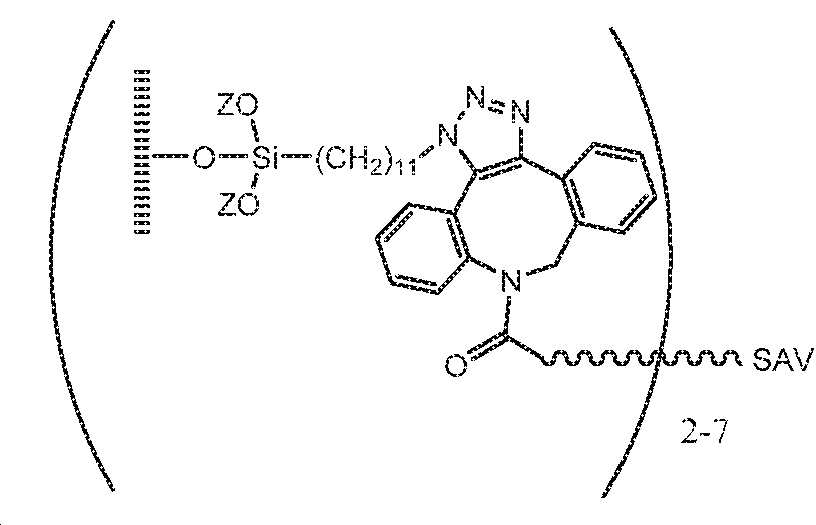
예 3. DBCO-표지된 스트렙타비딘 (SAV) 화합물 1의 합성: 5 mg 의 동결 건조된 SAV (ThermoFisher PN # S888) 를 1X PBS 에서 1 mL의 1X PBS (Gibco) 및 1 mL의 2 mM Na2CO3 (Acros) 에 용해시켰다. 10Mg 의 깔끔한 DBCO-PEG13-NHS (화합물 2, 클릭 화학 도구 PN # 1015-10) 을 0.4 mL 의 건조 DMSO에 용해시켰다. 16 uL 의 DBCO-PEG13-NHS 용액을 SAV 용액에 첨가하고 25 ℃ 에서 400 RPM으로 Eppendorf ThermoMixer에서 4 시간 동안 혼합하였다. 표지된 SAV (화합물 1) 를 반응 혼합물을 Zeba 크기 배제 크로마토 그래피 스핀 컬럼 (ThermoFisher PN #89882)을 통해 통과시킴으로써 DBCO-PEG13-NHS로부터 정제하고, 추가 정제없이 사용되었다.Example 3. Synthesis of DBCO-labeled streptavidin (SAV) compound 1 : 5 mg of lyophilized SAV (ThermoFisher PN # S888) in 1X PBS in 1 mL of 1X PBS (Gibco) and 1 mL of 2 mM Na2CO3 (Acros). 10Mg of neat DBCO-PEG13-NHS (

예 4. 스트렙타비딘 관능화된 표면을 갖는 평면 비 패턴 화 실리콘 웨이퍼의 제조. 상기 기술된 바와 같은 화학식 I 의 표면을 갖는 예 1의 생성물 실리콘 웨이퍼를 실리콘 웨이퍼를 2 마이크로몰 화합물 1을 함유하는 수용액과 접촉시킴으로써 화합물 1 (PEG 13 연결기를 갖는 예 3의 생성물 인 DBCO 연결된 스트렙타비딘 (SAV), 여기서 SAV 의 각 분자에 대해 2-7 DBCO 가 조재함) 으로 처리 하였다. 반응을 실온에서 1 시간 이상 동안 진행시켰다. 이어서 PEG 13 연결기를 포함하는 스트렙타비딘 공유결합으로 관능화된 표면을 갖는 비패턴화된 실리콘 웨이퍼를 1xPBS로 헹구었다. Example 4. Preparation of a flat non-patterned silicon wafer with a streptavidin functionalized surface . DBCO linked streptavi, a product of Example 1 with a PEG 13 linker, by contacting the product silicon wafer of Example 1 with the surface of Formula I as described above with an aqueous solution containing 2
예 5. 화합물 1 을 사용한 관능화와 비교하여 시판되는 DBCO 연결 SAV를 사용한 실리콘 웨이퍼의 관능화의 비교 SAV 개질된 표면의 비교는 반응성 아지드 모이어티의 도입의 각 단계 후 엘립 소메트리 및 접촉각 고니오메트리 (실시 예 1)에 의해 이루어졌다; 각각의 SAV 층의 도입; 이어서, 시약 농도 및 반응 조건이 동일한 비오틴화된 항-CD28을 도입 하였다. PEG13 모이어티를 포함하는 연결기를 갖는 DBCO SAV 시약을 사용하는 샘플 2 는 샘플 1의 것보다 더 강력한 SAV의 관능화를 제공하였고, 이어서 SAV 결합 부위에 비오틴화된 항-CD2 결합에 의한 보다 강력한 관능화를 제공 하였다. Example 5. Comparison of functionalization of silicon wafers using commercially available DBCO-linked SAV compared to functionalization with
(옹스트롬)Overall thickness after DBCO SAV coupling
(Angstrom)
(옹스트롬)Overall thickness after anti-CD 28 binding
(Angstrom)
이론에 구속되지 않고, 적어도 5 개의 PEG 반복 단위, 최대 약 20 개의 PEG 반복 단위의 길이를 갖는 연결기 (대안적으로, 약 20 Å 내지 약 100 Å 길이를 갖는 연결기) 가 실리콘 웨이퍼의 이 반응성 표면상의 반응성 모이어티에 우수한 수준의 커플링을 제공 할 수 있는 것으로 밝혀졌다. 이는 더 많은 SAV 결합 부위가 이용 가능하므로 샘플 웨이퍼 2에 도입된 항-CD28 층의 추가 두께에 의해 추가로 입증된다. Without being bound by theory, a linker having a length of at least 5 PEG repeat units, up to about 20 PEG repeat units (alternatively, a linker having a length of about 20
예 6. 평면 패턴화된 표면의 제조, 및 활성화 작용화를 갖지 않는 상이한 영역에 의해 분리된 복수의 영역 내에 항원 제시 표면을 제공하기 위한 추가의 구체화. 인듐 주석 산화물 (ITO) 웨이퍼가 그 ITO 상에 비정질 실리콘의 패턴화된 복수의 영역을 갖도록 제조되었다. 영역들은 a) 서로 3 미크론만큼 분리된 1 미크론 직경의 원형 비정질 실리콘 영역 또는 b) 서로 2 미크론만큼 분리된 2 미크론 사각형 비정질 실리콘 영역이었다. 도 6a 및 도 6b 는 각 유형의 패턴화된 표면의 부분들의 SEM 이미지를 도시한다. Example 6. Preparation of a planar patterned surface, and further refinement to provide an antigen presenting surface within a plurality of regions separated by different regions without activation functionalization. An indium tin oxide (ITO) wafer was made to have a plurality of patterned regions of amorphous silicon on the ITO. The regions were either a) a 1 micron diameter circular amorphous silicon region separated by 3 microns from each other or b) a 2 micron square amorphous silicon region separated by 2 microns from each other. 6A and 6B show SEM images of portions of each type of patterned surface.
패턴화된 웨이퍼를 아세톤에서 10 분 동안 초음파 처리하여 기능화하기 전에 세정하고, 탈 이온수로 린싱하고 건조시켰다 (도 6 의 단계 1). 패턴화된 웨이퍼는 그 후 100 W 전력, 240 mTorr 압력 및 440 sccm 산소 유량을 사용하여, 5 분 동안 산소 플라즈마 세정기 (Nordson Asymtek) 에서 처리되었다. The patterned wafer was sonicated in acetone for 10 minutes prior to functionalization, rinsed with deionized water and dried (
관능화 처리의 개략적인 표현이 도 6 에 도시되어 있다. ITO 표면의 초기 공유결합 개질. 웨이퍼의 인듐 주석 산화물베이스 층을 50 % N-메틸피롤리딘 (NMP) / 수용액에서 40mM 운데시닐 포스폰산 (Sikemia Catalog # SIK7110-10)과의 반응에 의해 관능화켰다 (도 6의 단계 2). 웨이퍼의 세정된 표면을 바이알 내 용액에 침지시키고 밀봉 하였다. 바이알을 50 ℃ 수조에서 밤새 유지시켰다. 다음날, 웨이퍼를 제거하고 50 % 이소프로필 알코올 / 물로 세척한 다음 이소 프로필 알코올로 세척 하였다. A schematic representation of the functionalization treatment is shown in FIG. 6. Initial covalent modification of the ITO surface. The indium tin oxide base layer of the wafer was functionalized by reaction with 50 mM N-methylpyrrolidine (NMP) / 40mM undecynyl phosphonic acid (Sikemia Catalog # SIK7110-10) in aqueous solution (
A. 패턴화된 표면의 ITO 영역의 비오틴화. 알킨 작용기화된 ITO 영역은 아지도 반응성 모이어티 (azide-SS-biotin, Broadpharm Catalog # BP-2877), 0.5 mM 아스코르브산 나트륨; 및 수중의 1mM Cu (II) SO4 / THPTA (도 6의 단계 3)에 연결된 1.5 mM 비오틴과의 반응에 의해 추가로 공유결합 개질되었다. 디술피드 함유 비오틴 시약과 접촉하기 전에 구리 리간드 및 나트륨 아스코르베이트를 예비 혼합하도록 주의를 기울였다. 표면을 1 시간 동안 비오틴 시약 용액과 접촉된 상태로 유지시켰다. 이어서 웨이퍼의 표면을 물로 세척하고, 다음 단계를 위해 제조하여 건조시켰다. A. Biotinylation of the ITO region of the patterned surface. The alkyne functionalized ITO region includes azido-reactive moieties (azide-SS-biotin, Broadpharm Catalog # BP-2877), 0.5 mM sodium ascorbate; And 1.5 mM biotin linked to 1 mM Cu (II) SO4 / THPTA (
B. 패턴화된 웨이퍼의 복수의 비정질 실리콘 영역의 표면의 공유 결합 개질. 웨이퍼의 ITO 영역 내의 비오틴화된 표면을 갖는 패턴화된 웨이퍼들은 진공 반응기의 하단의 별개의 호일 보트에서 물 반응원으로서, 황산 마그네슘 헵타하이드레이트 (0.5 g, Acros Cat# 10034-99-8) 의 존재 시에 진공 반응기의 하단의 호일 보트에서 (11-아지도운데실) 트리메톡시 실란 (화합물 3, 300 마이크로리터) 으로 진공 반응기에서 처리되었다 (도 6의 단계 4). 챔버는 그 후, 진공 펌프를 사용하여 750 mTorr 로 펌핑되었고 그 후 실링되었다. 진공 반응기는 밤새도록 110 ℃ 에서 가열된 오븐 내에 배치되었다. 이것은 개질된 표면을 웨이퍼상의 복수의 비정질 실리콘 영역에 도입하였고, 여기서 개질된 표면은 화학식 I 의 구조를 갖는다: B. Covalent modification of the surface of a plurality of amorphous silicon regions of a patterned wafer . Patterned wafers with a biotinylated surface in the ITO region of the wafer are the presence of magnesium sulfate heptahydrate (0.5 g, Acros Cat # 10034-99-8) as a water reactant in a separate foil boat at the bottom of the vacuum reactor. Was treated in a vacuum reactor with (11-azidoundecyl) trimethoxy silane (

실온으로 냉각시키고 배기된 챔버로 아르곤을 주입한 후에, 웨이퍼는 반응기로부터 제거되었다. 웨이퍼는 아세톤, 이소프로판올로 린스되고, 질소 스트림 하에서 건조되었다. 계측은 패터닝된 웨이퍼의 비오틴화된 ITO 영역이 화학식 I의 작용기 리간드의 실질적인 양의 오염을 갖지 않았으며; 10 % 이하의 오염 물질이 발견되었다.After cooling to room temperature and injecting argon into the vented chamber, the wafer was removed from the reactor. The wafer was rinsed with acetone, isopropanol and dried under a stream of nitrogen. Metrology indicated that the biotinylated ITO region of the patterned wafer had no substantial amount of contamination of functional group ligands of Formula I; Less than 10% of contaminants were found.
C.지지 모이어티를 제공하기 위해 패터닝된 웨이퍼의 비오틴-개질된 ITO 영역의 공유결합 개질. 비오틴 개질된 ITO 영역에 의해 분리된 복수의 운데실 아지도 개질된 비정질 실리콘 영역을 갖는 패턴 화된 웨이퍼를 0.02 % 아지드화 나트륨을 함유하는 PBS 중의 스트렙타비딘 (SAV, 3.84 마이크로 몰)의 용액과 반응시키고 30 분 동안 인큐베이션시켰다 (도 6 의 단계 5). 고체를 PBS 로 세척하고, 건조시킨다. C. Covalent modification of the biotin-modified ITO region of the patterned wafer to provide a support moiety. A patterned wafer with amorphous silicon regions modified with a plurality of undecyl azidoes separated by biotin-modified ITO regions was added with a solution of streptavidin (SAV, 3.84 micromolar) in PBS containing 0.02% sodium azide. The reaction was allowed to incubate for 30 minutes (
이어서, 패턴 화된 웨이퍼의 ITO 영역의 스트렙타비딘 개질된 표면은 0.02 % 나트륨 아지드를 함유하는 PBS 중 200 마이크로 몰의 비오틴-RGD 용액 (Anaspec Catalog # AS-62347)과의 반응에 의해 개질되어, 이들 표면상에서 배양될 때 T 림프구의 생존력에서의 일반적인 개선을 위한 접착제 모이어티를 제공한다 (도 6의 단계 6). 45 분 동안 인큐베이션 한 후, 웨이퍼를 PBS로 헹구고 건조시켰다.The streptavidin-modified surface of the ITO region of the patterned wafer was then modified by reaction with 200 micromolar biotin-RGD solution in PBS containing 0.02% sodium azide (Anaspec Catalog # AS-62347), Gluing moieties provide a general improvement in the viability of T lymphocytes when cultured on these surfaces (step 6 in Figure 6). After incubation for 45 minutes, the wafer was rinsed with PBS and dried.
추가의 일반화. 패터닝된 웨이퍼의 ITO 영역의 스트렙타비딘 개질된 표면은 대안 적으로 패턴화된 표면의 -활성화 영역 내에서 친수성 모이어티를 제공하기 위해 200 마이크로 몰의 비오틴-PEG-5K (Jenkem Catalog # M-BIOTIN-5000) 용액과의 반응에 의해 개질 될 수 있다. . 추가로, 스트렙타비딘 표면은 스트렙타비딘 표면을 비오틴화된 모이어티의 200 마이크로 몰 스톡 용액의 혼합물과 임의의 비, 예를 들어 1:1:1:10; 10 : 1 또는 그 사이의 임의의 비율로 반응시킴으로써 접착성 및 친수성 모이어티의 혼합물에 의해 개질될 수 있다. Additional generalizations. The streptavidin-modified surface of the ITO region of the patterned wafer is alternatively 200 micromolar biotin-PEG-5K (Jenkem Catalog # M-BIOTIN to provide a hydrophilic moiety within the active region of the patterned surface. -5000) It can be modified by reaction with solution. . Additionally, the streptavidin surface can be prepared in any ratio with a mixture of 200 micromolar stock solutions of biotinylated moieties on the streptavidin surface, for example 1: 1: 1: 10; It can be modified by a mixture of adhesive and hydrophilic moieties by reacting at a ratio of 10: 1 or between.
D. 패터닝된 웨이퍼의 복수의 아지도 관능화된 비정질 실리콘 영역에 2 차 관능화된 표면을 제공하는 단계. 0.02 % 소듐 아지드를 함유하는 PBS 중의 DBCO-SAV (Nanocs Catalog # SV1-DB-1, 2 micromolar)의 용액을 그 위에 공유적으로 부착된 지지 모이어티 (예를 들어, RGD와 같은 접착성 모티프 또는 PEG-5K와 같은 친수성 모이어티) 를 갖는 ITO 의 영역에 의해 분리된 복수의 아지도 작용화 비정질 실리콘 영역을 갖는 패턴화된 웨이퍼와 30 분의 인큐베이션 기간 동안 접촉시켜 지지 개질된 ITO 영역에 의해 분리된 스트렙타비딘 관능화된 표면을 갖는 복수의 비정질 영역을 제공한다. (도 6의 단계 7). 항원 활성화 리간드의 최종 도입까지 패턴 화된 웨이퍼를 PBS / 0.02 % 아 지드화 나트륨으로 유지시켰다. D. Providing a secondary functionalized surface to the amorphous silicon region functionalized with a plurality of ajido of the patterned wafer. A support moiety covalently attached to a solution of DBCO-SAV (Nanocs Catalog # SV1-DB-1, 2 micromolar) in PBS containing 0.02% sodium azide (eg, an adhesive motif such as RGD) Or a plurality of azido separated by regions of ITO with hydrophilic moieties such as PEG-5K) by a patterned wafer having functionalized amorphous silicon regions and contacted during a 30 minute incubation period to support modified ITO regions. It provides a plurality of amorphous regions with separated streptavidin functionalized surfaces. (
E. 패터닝된 웨이퍼의 비정질 실리콘 영역의 스트렙타비딘 개질된 표면의 기능화 (도 6의 단계 8). 단계적 관능화는 실시 예 12 에서와 유사하게 수행되고, 먼저 패턴 화된 표면을 비오틴 화된 단량체 MHC (HLA-A * 02:01 MART-1 (MBL International Corp., 카탈로그 번호 MR01008, ELAGIGILTV)에 용액중에 노출시키고 45 분 동안 배양에 노출시켰다. 워시 버퍼로 복수의 MHC 개질된 비정질 실리콘 영역을 갖는 패터닝된 웨이퍼를 린싱한 후, 패터닝된 웨이퍼를 비오틴화된 항-CD28 용액 (Miltenyi Biotec, 카탈로그 번호 130-100-144)과 접촉시키고 30-45 분 동안 인큐베이션하여 패턴 화된 웨이퍼의 지지 개질된 ITO 영역에 의해 분리된 복수의 pMHC / 항-CD28 영역을 제공한다. E. Functionalization of the streptavidin-modified surface of the amorphous silicon region of the patterned wafer (
예 7. pMHC 및 항-CD28이 연결된 복수의 영역을 포함하고, 패턴화되지 않은 표면에 비해 지지 모이어티가 연결된 영역에 의해 분리된 패턴 화된 표면을 사용하여 CD8+ T 림프구의 활성화. 실시 예 6의 생성물 패턴 화된 웨이퍼는 48- 웰 플레이트의 웰의 바닥 내에 배치하기 위해 크기가 정해졌다. 2 개의 상이한 패턴 화된 표면이 사용되었고, 첫 번째는 도 7a 에 도시된 바와 같이 직경이 1 미크론 인 원형 영역을 갖고 두번 째는 도 7b 에 도시된 바와 같이 각변이 2 미크론의 정사각형 영역을 갖는다. 동일한 수준의 MHC 펩티드 변형 및 항-CD28의 무작위 분포를 갖는 비 패턴 화 평면 제 3 표면을 제 3 48 웰 플레이트의 제 3 웰에 사용 하였다. 평면 표면에 로딩되는 한 수준의 항-CD28 항체 만이 사용되었다. 실시 예 12에 기재된 바와 같이 수득된 나이브 T- 림프구 (하기)를 웰 플레이트의 웰 내에 배치하고 패턴 화되거나 패턴 화되지 않은 웨이퍼와 접촉시켰다. 자극 프로토콜 및 배양 프로토콜은 각각 1 내지 7 일 동안 실시 예 12에서와 같이 수행되었다. 유세포 분석은 나이브 T 림프구의 활성화를 보여 주었다. 유세포 분석 결과는 도 8a 내지 도 8d 에 도시된 바와 같이 3 가지 종류의 표면 각각이 T 림프구를 활성화시킬 수 있음을 보여준다. 이들 3 가지 활성화 조건에 대한 도 8a 내지 도 8d 에 도시된 그래픽 특성은 표현형 특이성이 수득됨을 보여준다. 도 8a는 1 미크론 활성화 아일랜드 패턴, 2 미크론 활성화 아일랜드 패턴 및 비패턴 웨이퍼 표면 각각에 대해 생성물 세포 집단에서 발견된 항원 특이적 (MART1) T 세포의 백분율을 나타낸다. 도 8b는 각각의 표면 유형에 대한 각각의 생성된 세포 집단에서 발견된 MART 1 항원 특이적 T 세포의 총 수를 나타낸다. 도 8C는 각각의 표면 유형에 대한 MART 1 항원 특이적 T 세포의 배가 확장을 보여준다. 도 8d 는 각각의 표면 유형에 대한 항원 특이적 T 세포 집단 내에서 항원 특이적 T 세포를 발현시키는 CD28high 의 백분율을 보여준다. 패턴 화된 표면은 보다 재현 가능하고 제어 가능한 양의 증식, 표현형 및 실제 세포 수를 나타낸다. 더 작은 1 미크론 영역은 제시된 항원, MHC 분자 및 항-CD 28의 자연적인 바람직한 배열을 보다 효과적으로 모방 할 수 있다. 도 9 참조. Example 7. Activation of CD8 + T lymphocytes using a patterned surface comprising a plurality of regions linked with pMHC and anti-CD28 and separated by regions with support moieties compared to an unpatterned surface. The product patterned wafer of Example 6 was sized for placement within the bottom of a well of a 48-well plate. Two different patterned surfaces were used, the first one having a circular area of 1 micron in diameter as shown in FIG. 7A and the second one having a 2 micron square area on each side as shown in FIG. 7B. A non-patterned planar third surface with the same level of MHC peptide modification and random distribution of anti-CD28 was used for the third well of the third 48 well plate. Only one level of anti-CD28 antibody loaded onto a flat surface was used. The naive T-lymphocytes (below) obtained as described in Example 12 were placed in wells of well plates and contacted with patterned or unpatterned wafers. Stimulation protocol and culture protocol were performed as in Example 12 for 1 to 7 days, respectively. Flow cytometry analysis showed activation of naive T lymphocytes. The flow cytometry results show that each of the three types of surfaces can activate T lymphocytes, as shown in FIGS. 8A-8D. The graphic properties shown in FIGS. 8A-8D for these three activation conditions show that phenotypic specificity is obtained. 8A shows the percentage of antigen specific (MART1) T cells found in the product cell population for each 1 micron activated island pattern, 2 micron activated island pattern and unpatterned wafer surface. 8B shows the total number of
자극의 제 1 기간이 완료된 후, 생성된 T 세포를 웰플레이트의 동일한 웰 내에서 7-14 일 동안, 및 임의로 14-21 일 동안 재 자극하여 상기와 같은 사이토카인 첨가물을 첨가한다. 대안 적으로, 7 일 및 / 또는 14 일에, 생성된 T 림프구를 새로운 패턴 화된 웨이퍼를 갖는 새로운 웰로 이동시킬 수 있고, 실시 예 12의 프로토콜은 계속되었다. 원하는 자극 반복이 끝나면, 세포의 일부가 염색되고 활성화 정도를 결정하기 위해 유세포 분석법에 의해 검사 될 수 있다. 패턴 화된 표면 웨이퍼는 비드-기반 활성화 또는 항원 제시 수지상 세포에 의한 활성화만큼 쉽게 T 세포 활성화를 자극 할 것으로 예상된다. After the first period of stimulation is complete, the resulting T cells are re-stimulated in the same well of the well plate for 7-14 days, and optionally 14-21 days to add such a cytokine additive. Alternatively, on
예 8. 식 I 의 개질된 내부 표면을 갖는 미세유체 디바이스의 제조. 제 1 실리콘 전극 활성화 기판 및 반댁 벽에 제 2 ITO 기판, 및 2 개의 기판을 분리하는 광패턴화된 실리콘 미세유체 회로 재료를 갖는 상기 일반적 실험 섹션에서 기술된 미세유체 디바이스 (Berkeley Lights, Inc.) 는 100 W 전력, 240 mTorr 압력 및 440 sccm 산소 유량을 사용하여, 1 분 동안 산소 플라즈마 세정기 (Nordson Asymtek) 에서 처리되었다. 플라즈마 처리된 미세유체 디바이스는, 진공 반응기의 하단의 별개의 호일 보트에서 물 반응원으로서, 황산 마그네슘 헵타하이드레이트 (0.5g, Acros) 의 존재 시에 진공 반응기의 하단의 호일 보트에서 3-아지도운데실) 트리메톡시실란 (300 마이크로리터) 으로 진공 반응기에서 처리되었다. 챔버는 그 후, 진공 펌프를 사용하여 750 mTorr 로 펌핑되었고 그 후 실링되었다. 진공 반응기를 110 ℃에서 2448 시간 동안 가열된 오븐 내에 두었다. 이것은 개질된 표면을 미세유체 디바이스에 도입하였고, 여기서 개질된 표면은 화학식 I 의 구조를 가졌다 : Example 8. Preparation of a microfluidic device having a modified inner surface of formula I. The microfluidic device (Berkeley Lights, Inc.) described in the above general experimental section with a first silicon electrode activated substrate and a second ITO substrate on a half-duck wall, and a photopatterned silicon microfluidic circuit material separating the two substrates. Was treated in an oxygen plasma scrubber (Nordson Asymtek) for 1 minute, using 100 W power, 240 mTorr pressure and 440 sccm oxygen flow rate. The plasma-treated microfluidic device is a source of water in a separate foil boat at the bottom of the vacuum reactor, 3-azido in the foil boat at the bottom of the vacuum reactor in the presence of magnesium sulfate heptahydrate (0.5 g, Acros). Sil) Trimethoxysilane (300 microliters) was treated in a vacuum reactor. The chamber was then pumped to 750 mTorr using a vacuum pump and then sealed. The vacuum reactor was placed in a heated oven at 110 ° C. for 2448 hours. This introduced the modified surface to the microfluidic device, where the modified surface had the structure of formula I:

실온으로 냉각시키고 배기된 챔버로 아르곤을 주입한 후에, 미세유체 디바이스는 반응기로부터 제거되었다. 기능화된 표면을 갖는 미세유체 디바이스를 250 마이크로 리터 이상의 탈 이온수로 헹구고, 추가로 사용할 제조가되었다.After cooling to room temperature and injecting argon into the vented chamber, the microfluidic device was removed from the reactor. A microfluidic device with a functionalized surface was rinsed with at least 250 microliters of deionized water and made ready for further use.
예 9. 미세유체 디바이스 내의 T-세포 활성화 표면의 도입 Example 9. Introduction of T-cell activated surfaces in microfluidic devices
A. OptoSelect 미세유체 디바이스의 내부 표면은 실시 예 8 (화학식 I)에서와 같이 아지도 모이어티를 포함하도록 공유 변형되었다. 스트렙타비딘으로 표면을 기능화하기 위해, OptoSelect 미세 유체 디바이스를 먼저 100 % 이산화탄소로 반복적으로 플러싱 한 다음, 실시 예 4에서 생성된 바와 같이 약 0.5 내지 약 2 마이크로 몰의 농도를 갖는 DBCO- 스트렙타비딘 용액으로 로딩 하였다. DBCO 및 아지드 기들이 커플링했던 15-30 분 동안의 인큐베이션 후에, OptoSelect 미세유체 디바이스는 비결합된 DBCO-개질된 스트렙타비딘을 플러싱하기 위해 1X PBS 로 반복적으로 세척되된다. A. The inner surface of the OptoSelect microfluidic device was covalently modified to include an azido moiety as in Example 8 (Formula I). To functionalize the surface with streptavidin, the OptoSelect microfluidic device is first repeatedly flushed with 100% carbon dioxide, then DBCO-streptavidin having a concentration of about 0.5 to about 2 micromolar as produced in Example 4. It was loaded with solution. After 15-30 minutes of incubation with DBCO and azide groups coupled, the OptoSelect microfluidic device is washed repeatedly with 1X PBS to flush unbound DBCO-modified streptavidin.
이어서, 이 스트렙타비딘 표면을 비오틴화 pMHC, 및 비오틴화 항 CD28, 비오틴화 항 CD2 또는 이들의 임의의 조합 중의 선택으로 추가로 변형시킨다. 이들 분자는 약 2:1 내지 약 1:2의 pMHC 분자 대 항 CD28 / 항 CD2의 비로 약 1 내지 10 마이크로 그램 / mL의 농도로 2 % 소 혈청 알부민과 함께 PBS에 현탁된다. 이 용액은 스트렙타비딘 관능화된 표면을 갖는 OptoSelect 미세유체 디바이스를 통해 관류되어 표면과의 공액을 촉진시킨다. 1 시간의 배양 후, 세포를 로딩하기 전에 OptoSelect 미세유체 디바이스를 PBS 또는 매질로 플러싱한다.This streptavidin surface is then further modified with a choice of biotinylated pMHC, and biotinylated anti-CD28, biotinylated anti-CD2, or any combination thereof. These molecules are suspended in PBS with 2% bovine serum albumin at a concentration of about 1 to 10 micrograms / mL at a ratio of pMHC molecule to anti CD28 / anti CD2 from about 2: 1 to about 1: 2. This solution is perfused through an OptoSelect microfluidic device with a streptavidin functionalized surface to promote conjugation with the surface. After 1 hour of incubation, the OptoSelect microfluidic device is flushed with PBS or medium before loading the cells.
B. 대안 적으로, 관심있는 생체 분자는 OptoSelect 미세유체 디바이스의 아지도-개질된 표면과의 반응 전에 생체 분자의 스트렙타비딘으로의 비오틴 변형을 통해 접합된다. DBCO-스트렙타비딘 및 비오티닐레이티드 생체분자는 이하에 기술된 바와 같이, 0.5 - 2 마이크로몰의 범위에서의 농도들에서 PBS 용액에서 별개로 제조되고, 그 후 임의의 원하는 비율로 혼합될 수 있다. 비오티닐레이티드 생체분자들이 적어도 15 분 동안 스트렙타비딘 대해 컨쥬게이트하는 것을 허용한 후, 결과의 착체들은 상술된 바와 같이 아지도-개질된 OptoSelect 미세유체 디바이스의 표면을 개질하기 위해 사용될 수 있다. B. Alternatively, the biomolecule of interest is conjugated via biotin modification of the biomolecule to streptavidin prior to reaction with the azido-modified surface of the OptoSelect microfluidic device. DBCO-streptavidin and biotinylated biomolecules are prepared separately in PBS solution at concentrations in the range of 0.5-2 micromolar, as described below, and then mixed in any desired ratio. Can. After allowing biotinylated biomolecules to conjugate to streptavidin for at least 15 minutes, the resulting complexes can be used to modify the surface of an azido-modified OptoSelect microfluidic device as described above. .
세포는 하나 이상의 항원 제시 내부 표면을 갖는 미세유체 디바이스 내로 수입 될 수 있고, 실시 예 19의 항원 제시 비드에 의한 T 세포의 활성화에 대해 기술된 것과 유사하게 배양 기간 동안 활성화 될 수 있다. Cells can be imported into a microfluidic device having one or more antigen presenting inner surfaces, and can be activated during the culture period, similar to that described for activation of T cells by the antigen presenting beads of Example 19.
예 10. 실리카 비드의 공유 변형 및 기능화. Example 10. Covalent modification and functionalization of silica beads.
10A 스트렙타비딘에 연결된 공유 PEG 3 이황화 비오틴을 갖는 실리카 비드. 구형 실리카 비즈 (2.5 미크론, G 바이오 사이언스 카탈로그 번호 786-915, 실질적으로 단순한 구형 부피를 갖는 것, 예를 들어 비드의 표면적은 관계식 4πr2 +/- 10 % 이하에 의해 예측된 범위 내에있는 것)를 이소프로판올에 분산시킨 다음 건조시켰다. 건조된 비드들은 100 W 전력, 240 mTorr 압력 및 440 sccm 산소 유량을 사용하여, 5 분 동안 산소 플라즈마 세정기 (Nordson Asymtek) 에서 처리되었다. 세정된 비드들은 진공 반응기의 하단의 별개의 호일 보트에서 물 반응원으로서, 황산 마그네슘 헵타하이드레이트 (0.5 g, Acros Cat# 10034-99-8) 의 존재 시에 진공 반응기의 하단의 호일 보트에서 (11-아지도운데실) 트리메톡시 실란 (300 마이크로리터) 으로 진공 반응기에서 처리되었다. 챔버는 그 후, 진공 펌프를 사용하여 750 mTorr 로 펌핑되었고 그 후 실링되었다. 진공 반응기를 110 ℃에서 24-48 시간 동안 가열된 오븐 내에 두었다. 이것은 공유결합으로 개질된 표면을 비드들에 도입하였고, 여기서 개질된 표면은 화학식 I 의 아지드 관능화된 구조를 가졌다 : Silica beads with
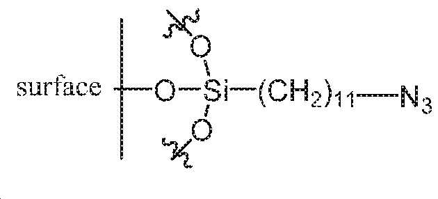
실온으로 냉각하고 배기된 챔버에 아르곤을 도입한 후, 공유결합으로 개질된 비드들이 반응기로부터 제거되었다. 아지드 반응성 모이어티들로 관능화된 공유결합으로 개질된 표면을 갖는 비드들은 아세톤, 이소프로판올로 린싱되고, 질소의 스트림 하에서 건조되었다. 공유결합으로 개질된 아지드 관능화된 비드들은 디벤질시클로옥티닐 (DBCO) S-S 비오틴 개질된-PEG3 (브로드팜, Cat. #BP-22453) 의 5.7 mM DMSO 용액 중에 1 mg/20 마이크로리터의 농도로 분산되고, 그 후 18 시간 동안 열혼합기 (thermomixer) 에서 90℃/2000 RPM 으로 배양되었다. 비오틴 개질된 비드들은 초과의 DMSO 에서 각각 3 번 세척되었고, 그 후 PBS 로 린싱되었다. PBS 에서의 비오틴 개질된 비드들은 대략 30 마이크로몰/700 마이크로리터 농도 스트렙타비딘을 함유하는 PBS 용액 중에 분산되었다. 반응 혼합물은 30 분 동안 열혼합기에서 30℃/2000 RPM 으로 쉐이킹 (shaking) 되었다. 반응 주기의 완료 시에, 공유결합으로 개질된 비드 제시 스트렙타비딘은 초과의 PBS 에서 3 번 세척되었다. FTIR 분석은 SAV 가 표면에 첨가되었다고 결정했다 (데이터 미도시). 디술파이드 함유 링커는 표면으로부터의 균열이 바람직할 수도 있다면 특히 유용할 수도 있다. 디술파이드 링커는 T 림프구 생존 능력과 양립가능한 것으로 발견된 농도들에서의 디티오트레이톨을 갖는 균열에 민감하다 (데이터 미도시).After cooling to room temperature and introducing argon into the vented chamber, covalently modified beads were removed from the reactor. Beads with a covalently modified surface functionalized with azide reactive moieties were rinsed with acetone, isopropanol and dried under a stream of nitrogen. Covalently modified azide functionalized beads are 1 mg / 20 microliters of a 5.7 mM DMSO solution of dibenzylcyclooctynyl (DBCO) SS biotin modified-PEG3 (Broadfarm, Cat. # BP-22453). Dispersed in concentration, and then incubated at 90 ° C / 2000 RPM in a thermomixer for 18 hours. Biotin-modified beads were washed three times each in excess DMSO and then rinsed with PBS. Biotin-modified beads in PBS were dispersed in PBS solution containing approximately 30 micromolar / 700 microliter concentration streptavidin. The reaction mixture was shaken at 30 ° C / 2000 RPM in a heat mixer for 30 minutes. Upon completion of the reaction cycle, covalently modified bead-presenting streptavidin was washed 3 times in excess PBS. FTIR analysis determined that SAV was added to the surface (data not shown). Disulfide-containing linkers may be particularly useful if cracking from the surface may be desirable. The disulfide linker is sensitive to cracking with dithiothreitol at concentrations found to be compatible with T lymphocyte viability (data not shown).
10B. PEG5-카르복시산 표면-차단 분자 리간드들로 희석된 스트렙타비딘에연결된 공유결합 PEG4 비오틴을 갖는 실리카 비드들. 예 10A 에서 상술된 바와 같이 준비된, 식 1 의 아지드 반응성 모이어티들로 관능화된 공유결합으로 개질된 표면을 갖는 비드들은 아세톤, 이소프로판올로 린싱되었고, 질소의 스트림 하에서 건조되었다. 공유결합으로 개질된 아지드 관능화된 비드들은 0.6 mM 디벤질시클로옥티닐 (DBCO)-개질된-PEG4-비오틴 (브로드팜, Cat. #BP-22295), 5.4 mM 디벤질시클로옥티닐 (DBCO)-개질된-PEG5-카르복시산 (브로드팜, Cat. #BP-22449), 및 100 mM 요오드화나트륨의 DMSO 용액 중에 1 mg/10 마이크로리터의 농도로 분산되었고 그 후 18 시간 동안 열혼합기에서 30℃/1000 RPM 으로 배양되었다. 비오틴 개질된 비드들은 초과의 DMSO 에서 각각 3 번 세척되었고, 그 후 PBS 로 린싱되었다. PBS 내의 비오틴 개질된 비드들은 대략 10 나노몰/1 밀리리터 농도 스트렙타비딘을 함유하는 PBS 용액에 분산되었다. 반응 혼합물은 30 분 동안 열혼합기에서 30℃/1000 RPM 으로 쉐이킹되었다. 반응 주기의 완료 시에, 공유결합으로 개질된 비드 제시 스트렙타비딘은 초과의 PBS 에서 3 번 세척되었다. FTIR 분석은 SAV 가 표면에 첨가되었다고 결정했다 (데이터 미도시). 10B. Silica beads with covalent PEG4 biotin linked to streptavidin diluted with PEG5-carboxylic acid surface-blocking molecular ligands. Beads having a covalently modified surface functionalized with azide reactive moieties of
예 11. 폴리머 비드의 항원 제시 표면의 준비. 스트렙타비딘 관능화된 (공유결합으로 커플링된) 콘볼루트된 구형 폴리머 비드들 (예를 들어, 비드의 실제 표면적은 관계 표면적 = 4πr2 +/- 10% 이하보다 큼, DynaBeadsTM (서모피셔 카탈로그 # 11205D, 6.67e8/mL 의 비드 스톡)) 은 워시 버퍼 (Wash Buffer) (DPBS (마그네슘+2 없음, 칼슘+2 없음, 244 mL); EDTA (1ml, 최종 농도 2mM); 및 BSA (5% 의 5ml, 최종 농도 0.1%) 의 1 mL 를 갖는 1.5 mL 마이크로원심분리 튜브로 전달되었고 (15 마이크로리터; 1e7 비드들), 자기 DynaBead 랙을 사용하여 분리되었다. 1 mL 의 워시 버퍼를 갖는 세척/분리는 반복되었고, 추가의 200 마이크로리터의 워시 버퍼가 후속 펄스 원심분리로 첨가되었다. 상청액 워시 버퍼는 제거되었다. Example 11. Preparation of antigen-presenting surface of polymer beads. Streptavidin functionalized (covalently coupled) convoluted spherical polymer beads (e.g., the actual surface area of the beads is greater than the relationship surface area = 4πr 2 +/- 10% or less, DynaBeads TM (ThermoFisher) Catalog # 11205D, 6.67e8 / mL bead stock)) was Wash Buffer (DPBS (no magnesium +2, no calcium +2 , 244 mL); EDTA (1ml, final concentration 2mM); and BSA (5 % 5 ml, final concentration 0.1%) was transferred to a 1.5 mL microcentrifuge tube with 1 mL (15 microliters; 1e7 beads) and separated using a magnetic DynaBead rack Wash with 1 mL wash buffer / Separation was repeated and an additional 200 microliters of wash buffer was added by subsequent pulse centrifugation.The supernatant wash buffer was removed.
1.5 마이크로그램 비오틴화된 단량체 MHC (HLA-A* 02:01 MART-1 (MBL 인터네셔널 코포레이션, 카탈로그 번호 MR01008, ELAGIGILTV) 를 함유하는 워시 버퍼 (600 마이크로리터) 는 마이크로원심분리 튜브 내로 분산되었고, 비드들은 위 아래로 피펫팅함으로써 다시 부유되었다. 단량체는 4℃ 에서 30 분 동안 결합이 허용되었다. 15 분 후에, 혼합물은 다시 위 아래로 피펫팅되었다. 튜브는 펄스 원심분리되었고 상청액은 제거되었으며, 튜브는 비드들을 제거하지 않고 더 많은 상청액을 제거하기 위해 자기 랙 내에 배치되었다. Wash buffer (600 microliters) containing 1.5 microgram biotinylated monomer MHC (HLA-A * 02:01 MART-1 (MBL International Corporation, Cat. No. MR01008, ELAGIGILTV)) was dispersed into microcentrifuge tubes and beads They were suspended again by pipetting up and down The monomer was allowed to bind for 30 minutes at 4 ° C. After 15 minutes, the mixture was pipetted up and down again The tubes were pulse centrifuged and the supernatant was removed and the tubes were removed. Was placed in a magnetic rack to remove more supernatant without removing the beads.
600 마이크로리터 워시 버퍼 내의 비오틴화된 안티-CD28 (Miltenyi Biotec, 카탈로그 # 130-100-144, 22.5 마이크로리터) 의 용액이 마이크로원심분리 튜브에 첨가되었다. 비드들은 위 아래로 피펫팅함으로써 다시 부유되었다. 비드들은 4℃ 에서 30 분 동안 배양되어, 또 다른 위 아래 피펫팅에 의해 15 분 후에 다시 부유하였다. 배양 주기의 종단에서, 튜브는 간단하게 펄스 원심분리되었다. 자기 랙에 다시 배치하고 1 분 동안 분리를 허용한 후, 버퍼 용액은 관능화된 비드들로부터 흡입되었다. MHC 단량체/안티-CD28 항원 제시 비드들은 100 마이크로리터 버퍼 워시에서 다시 부유되고, 4℃ 에서 저장되고, 추가의 조작 없이 사용되었다. 1e7 2.80 마이크론 직경 관능화된 DynaBeads 은 T 림프구 세포와 접촉을 위해 이용가능한 약 24e6 제곱 미크론의 공칭 (구의 이상적 예측된 표면적) 표면적을 갖는다. 그러나, T 림프구 세포들에 의해 반드시 액세스가능하지는 않는 이러한 클래스의 폴리머 비드의 콘볼루션들이 또한 이러한 방법으로 관능화된다. 총 리간드 카운트는 T 림프구 세포들과 접촉하고 그들을 활성화하는데 이용가능한 것을 반영하지 않을 수도 있다.A solution of biotinylated anti-CD28 (Miltenyi Biotec, catalog # 130-100-144, 22.5 microliters) in 600 microliter wash buffer was added to the microcentrifuge tube. Beads were again floated by pipetting up and down. Beads were incubated at 4 ° C. for 30 minutes, and resuspended after 15 minutes by another up and down pipetting. At the end of the incubation cycle, the tube was simply pulse centrifuged. After placing back in the magnetic rack and allowing separation for 1 minute, the buffer solution was aspirated from the functionalized beads. MHC monomer / anti-CD28 antigen presenting beads were suspended again in a 100 microliter buffer wash, stored at 4 ° C. and used without further manipulation. The 1e7 2.80 micron diameter functionalized DynaBeads has a nominal (ideal predicted surface area of the sphere) surface area of about 24e6 square microns available for contact with T lymphocyte cells. However, convolutions of polymer beads of this class that are not necessarily accessible by T lymphocyte cells are also functionalized in this way. The total ligand count may not reflect what is available to contact and activate T lymphocyte cells.
MHC 단량체/안티-CD28 항원 제시 비드들은 Alexa Fluor 488-컨쥬게이티드 Rabbit 안티 Mouse lgG (H+L) 크로스-흡착된 2차 항체 (Invitrogen 카탈로그 # A-11059) 및 APC-컨쥬게이티드 안티-HLA-A2 항체 (Biolegend 카탈로그 # 343307) 로 스테이닝 (staining) 하는 것에 의해 특성화되었고, 유세포 분석에 의해 특성화되었다.MHC monomer / anti-CD28 antigen presenting beads were Alexa Fluor 488-conjugated Rabbit anti Mouse lgG (H + L) cross-adsorbed secondary antibody (Invitrogen Catalog # A-11059) and APC-conjugated anti-HLA Characterized by staining with -A2 antibody (Biolegend catalog # 343307) and characterized by flow cytometry.
예 12. 수지상 세포들에 의한 CD8+ T 림프구들의 활성화에 비교한 항원 제시 비드들에 의한 CD8+ T 림프구들의 활성화.Example 12. Activation of CD8 + T lymphocytes by antigen presenting beads compared to activation of CD8 + T lymphocytes by dendritic cells.
세포들: CD8+ T 림프구들은 네거티브 선택에 의해 EasySepTM Human CD8 Positive Selection Kit II, 즉 StemCell Technologies Canada Inc. 로부터의 상업적으로 이용가능한 키트 (카탈로그 # 17953) 에 대한 제조자의 지시들에 따라 상업적으로 이용가능한 PBMC 들로부터의 RPMI 플러스 10% 소태아혈청 (FBS) 을 포함하는 매질에서 풍부화 되었다.Cells: CD8 + T lymphocytes are negatively selected by EasySep TM Human CD8 Positive Selection Kit II, StemCell Technologies Canada Inc. It was enriched in a medium containing RPMI plus 10% fetal bovine serum (FBS) from commercially available PBMCs according to the manufacturer's instructions for a commercially available kit from (catalog # 17953).
수지상 세포들은: 오토로고스 PBMC 들로부터 생성되었다. 오토로고스 PBMC 들 (10-50 e6) 은 10% FBS 를 포함하는 10 mL 의 예열된 RPMI 매질들내로 해동되었다. 세포들은 400xg 에서 5 분 동안 원심분리함으로써 펠릿화되었다. 세포들은 RPMI 에서 다시 부유되고 카운트되었다. Dendritic cells were produced from: Autologos PBMCs. Autologos PBMCs (10-50 e6) were thawed into 10 mL of preheated RPMI media containing 10% FBS. Cells were pelleted by centrifugation at 400xg for 5 minutes. Cells were suspended and counted again in RPMI.
세포들은 제조자의 지시들에 따라 네거티브 비드 격리 (EasySepTM Human Monocyte Isolation Kit, StemCell Technologies, 카탈로그 # 19359) 를 사용하여 단핵구들에 대해 풍부화 되었다. 결과의 모노사이트가 카운트되어 약 5% 수율을 제공하고, 그 후 17 ng/mL IL-4 및 53 ng/mL Human Granulocyte Macrophage Colony-Stimulating Fact (GM-CSF, ThermoFisher 카탈로그 # PHC2013) 을 함유하는 AIM-V® 매질 (ThermoFisher 카탈로그 # 12055091) 내의 웰 당 3mL 당 1.5- 3e6 세포들로 플레이팅되었다. 세포들은 37℃ 에서 총 6일 동안 배양되었다. 2일 및 4일째에 100 마이크로리터의 공급 매질 (AIM-V® 매질 플러스 IL-4 (167 U/mL) 및 GM-CSF (540 ng/mL)) 이 각 웰에 첨가되었고, 배양이 계속되었다.Cells were enriched for monocytes using negative bead isolation (EasySep ™ Human Monocyte Isolation Kit, StemCell Technologies, catalog # 19359) according to the manufacturer's instructions. The resulting monosite is counted to give about 5% yield, then AIM containing 17 ng / mL IL-4 and 53 ng / mL Human Granulocyte Macrophage Colony-Stimulating Fact (GM-CSF, ThermoFisher Catalog # PHC2013) Plated with 1.5-3e6 cells per 3mL per well in -V® medium (ThermoFisher Catalog # 12055091). Cells were cultured at 37 ° C. for a total of 6 days. On
6 일째에, 0.5 mL 의 숙성 칵테일이 각 웰에 첨가되었다. 숙성 칵테일은 AIM-V® 매질에 10 ng/mL TNF-알파; 2 ng/mL IL-1B; 1000 U/mL IL-6, 1000 ng/mL PGE2; 167 U/mL IL-4 및 267 U/mL GM-CSF 를 포함했다. 세포들은 37℃ 에서 추가의 24 시간 동안 배양되었다. 숙성된 DC 들이 그 후 숙성 매질로부터 수집되고, 카운트되고, 추가의 사용을 위해 준비되었다. DC 들은 CD3 (BD 카탈로그 # 344828), DC-SIGN (CD209, 바이오레전드 카탈로그 # 330104), CD14 (바이오레전드 카탈로그 # 325608), CD86 (BD 카탈로그 # 560359), Fc Block (바이오레전드 카탈로그 # 422302), 및 생존능력 (BD 카탈로그 # 565388) 에 대한 스테이닝을 특징으로하였고; FACS 버퍼에서 부유되었고; 및 FACS 유세포분석에 의해 검사되었다.On day 6, 0.5 mL of the aging cocktail was added to each well. The aging cocktail contained 10 ng / mL TNF-alpha in AIM-V® medium; 2 ng / mL IL-1B; 1000 U / mL IL-6, 1000 ng / mL PGE2; 167 U / mL IL-4 and 267 U / mL GM-CSF. Cells were incubated for an additional 24 hours at 37 ° C. The aged DCs were then collected from the ripening medium, counted and ready for further use. DCs are CD3 (BD Catalog # 344828), DC-SIGN (CD209, Bio Legend Catalog # 330104), CD14 (Bio Legend Catalog # 325608), CD86 (BD Catalog # 560359), Fc Block (Bio Legend Catalog # 422302), And staining for viability (BD Catalog # 565388); Suspended in FACS buffer; And FACS flow cytometry.
항원을 제시하는 수지상 세포는 1% HSA 에서 2e6/mL 의 농도로 플레이팅하고 항원 (MART1 펩티드, Anaspec, 커스텀 합성, 40 마이크로그램/mL) 및 베타2-마이크로글로불린 (시그마 알드리치 카탈로그 # M4890, 3 마이크로그램/mL) 으로 펄싱하고, 그 후 4 시간 동안 교반과 함께 배양함으로써 제조되었다. 펄싱된 DC 들은 50 그레이의 목표 도즈로, 사용전에 30 분 동안 Faxitron CellRad® x-레이 셀 조사기에서 조사되었다.Dendritic cells presenting antigen are plated at a concentration of 2e6 / mL in 1% HSA and antigen (MART1 peptide, Anaspec, custom synthesis, 40 micrograms / mL) and beta2-microglobulin (Sigma Aldrich catalog # M4890, 3 Micrograms / mL) and then incubated with stirring for 4 hours. The pulsed DCs were irradiated on a Faxitron CellRad® x-ray cell irradiator for 30 minutes prior to use with a 50 gray target dose.
시약 첨가를 위한 배양 매질 및 희석제 : 고급 RPMI (ThermoFisher 카탈로그 번호 12633020, 500mL); 1x GlutaMAX (ThermoFisher 카탈로그 번호 35050079, 5mL); 10 % 인간 AB 혈청 (zen-bio, Catalog # HSER-ABP 100mL, 50mL); 및 50nM 베타-메르 캅토 에탄올 (ThermoFisher 카탈로그 번호 31350010, 50nm 스톡, 0.5mL, 최종 conc 50 마이크로 몰). Culture medium and diluent for reagent addition: advanced RPMI (ThermoFisher Catalog No. 12633020, 500 mL); 1x GlutaMAX (ThermoFisher Catalog No. 35050079, 5 mL); 10% human AB serum (zen-bio, Catalog # HSER-
실험 설정 : 각 활성화 종에 대해, 단일 96-웰 조직 배양 처리 플레이트 (VWR 카탈로그 번호 10062-902)를 사용 하였다 (웰 플레이트 1 (DC); 웰 플레이트 2 (항원 제시 비드)). CD8 + T 림프구 (2e5) (80-90 % 순도)를 각각의 개별 웰에 첨가 하였다. Experimental setup: For each activated species, a single 96-well tissue culture treated plate (VWR catalog number 10062-902) was used (well plate 1 (DC); well plate 2 (antigen presenting beads)). CD8 + T lymphocytes (2e5) (80-90% purity) were added to each individual well.
펄싱된 DC를 웰 플레이트 1에서 각 웰에 대해 5e3로 첨가하고, 1:40 비율의 DC:CD8 + T 림프구를 수득 하였다 : Pulsed DC was added at 5e3 for each well in
MART1 및 항-CD28 항체를 포함하는 pMHC를 제공하는 실시 예 11에서와 같이 제조된 항원 제시 표면 폴리머 비드 (2e5)를 웰 플레이트 2의 각 웰에 첨가 하였다. pMHC를 1.5 마이크로 그램 / 1e7 비드로 로딩 하였다. 항-CD 28 항체를 3 가지 상이한 수준으로 비드 상에 로딩 하였다 : 0.25 마이크로 그램 / 1e7 비드; 0.75 마이크로 그램 / 1e7 비드; 및 2.25 마이크로 그램 / 1e7 비드. Antigen presenting surface polymer beads (2e5) prepared as in Example 11 providing pMHC comprising MART1 and anti-CD28 antibody were added to each well of
각 웰 플레이트를 37 ℃에서 배양 하였다. 0 일에, CTL 매질 중의 IL-21 (150ng / 밀리리터)을 웰 플레이트 1 및 2 의 각 웰에 첨가하여, 각 웰에서 30 ng / mL의 최종 농도를 제공 하였다. 2 일에, IL21을 웰 플레이트의 각 웰에 최종 농도 30ng / mL로 첨가 하였다. 배양은 7 일까지 계속되었다. Each well plate was incubated at 37 ° C. On
7일. 각 웰 플레이트로부터의 웰의 서브 세트를 MHC 테트라머 (Tetramer PE, MBL 카탈로그 번호 T02000, 1 마이크로 리터 / 웰), CD4 (Biolegend 카탈로그 번호 300530, 0.5 마이크로 리터 / 웰); CD8 (Biolegend Catalog # 301048, 0.5 마이크로 리터 / 웰); CD28 (Biolegend 카탈로그 번호 302906, 0.31 마이크로 리터 / 웰); CD45RO (Biolegend Catalog # 304210, 0.63 마이크로 리터 / 웰); CCR7 (CD197, Biolegend 카탈로그 번호 353208, 0.5 마이크로 리터 / 웰); 및 생존력 (BD 카탈로그 번호 565388, 0.125 마이크로 리터 / 웰)에 대해 개별적으로 염색하였다. 각 웰을 150 마이크로 리터 FACS 완충액 및 10 마이크로 리터의 카운트 브라이트TM 비즈 (ThermoFisher 카탈로그 번호 C36950)로 재현탁시켰다. FACS 분석은 FACSCelestaTM 유세포 분석기 (BD Biosciences)에서 수행되었다. 도 10은 CD8 / MART1 표현형에 대한 유세포 분석에 대한 제브라 플롯을 보여준다. 제브라 플롯의 각 행 (1010, 1020, 1030 및 1040) 에 대해, 왼쪽 플롯은 대표적인 음성 웰이고 오른쪽 플롯은 대표적인 양성 웰이다. 1010 행은 DC 자극 웰 플레이트로부터의 웰이다. 1020, 1030 및 1040 행은 항원 제시 비드 자극 웰 플레이트로부터의 결과를 보여준다. 1020 행은 항-CD28 항체 로딩의 0.25 마이크로 그램 / 1e7 비드 및 pMHC의 1.5 마이크로 그램 / 1e7 비드에 대한 결과를 보여준다. 1030 행은 0.75 마이크로 그램 / 1e7 비드 항 CD28 항체 로딩 및 1.5 마이크로 그램 / 1e7 비드 pMHC에 대한 결과를 보여준다. 1040 행은 2.25 마이크로 그램 / 1e7 비드 항 CD28 항체 로딩 및 1.5 마이크로 그램 / 1e7 비드 pMHC에 대한 결과를 보여준다. 항원 제시 비드는 항-CD28 항체의 수준을 변화시킬 때 용량 / 반응 방식으로 활성화를 개시하고, MART1이 로딩된 MHC 펩티드는 항-CD28 로딩과 조합하여 T 림프구를 DC의 그것과 유사하게 활성화시키는데 충분하다는 것을 알 수 있다. 7 days. Subsets of wells from each well plate include MHC tetramer (Tetramer PE, MBL catalog number T02000, 1 microliter / well), CD4 (Biolegend catalog number 300530, 0.5 microliter / well); CD8 (Biolegend Catalog # 301048, 0.5 microliters / well); CD28 (Biolegend catalog number 302906, 0.31 microliters / well); CD45RO (Biolegend Catalog # 304210, 0.63 microliters / well); CCR7 (CD197, Biolegend catalog number 353208, 0.5 microliters / well); And viability (BD Catalog No. 565388, 0.125 microliters / well). Each well was resuspended in 150 microliter FACS buffer and 10 microliters of Count BrightTM beads (ThermoFisher Catalog No. C36950). FACS analysis was performed on a FACSCelestaTM flow cytometer (BD Biosciences). 10 shows a zebra plot for flow cytometry analysis for the CD8 / MART1 phenotype. For each row (1010, 1020, 1030 and 1040) of the zebra plot, the left plot is a representative negative well and the right plot is a representative positive well.
7일. 재 자극. 펄스 DC 또는 항원 제시 비드의 제 2 분취량을 각각 웰 플레이트 1 및 웰 플레이트 2에서 각각 점유된 웰에 전달 하였다. IL21을 웰 플레이트의 각 웰에 최종 농도 30ng / mL로 첨가 하였다. 배양이 계속되었습니다.7 days. Re-stimulation. A second aliquot of pulsed DC or antigen presenting beads was delivered to wells occupied in
8일. 웰 플레이트 1 및 웰 플레이트 2에서 각각의 웰에 50 마이크로 리터의 IL-2 (50 IU / mL) 및 IL-7 (25ng / mL)을 첨가하여 각각 10 IU / mL 및 5 ng / mL의 최종 농도를 제공 하였다 . 배양이 계속되었다.8th. Final concentrations of 10 IU / mL and 5 ng / mL, respectively, by adding 50 microliters of IL-2 (50 IU / mL) and IL-7 (25 ng / mL) to each well in
9일. 웰 플레이트 1 및 웰 플레이트 2 의 각각의 점유된 웰에 50 마이크로 리터의 IL-21 (150ng / mL)을 첨가하여 30ng / mL의 최종 농도를 제공 하였다 . 배양이 계속되었다.9th. To each occupied well of
14일. 각 웰 플레이트로부터의 웰의 제 2 서브 세트를 개별적으로 염색하고 7 일차 분석에 대해 기재된 바와 같이 FACS 분류 하였다. 유세포 분석 결과는 도 11 에 도시되어 있다. 각 행 (1110, 1120, 1130, 1140)에 대해 대표적 덜 포지티브 웰 (각 행의 왼손 그래프) 및 높게 포지티브 웰 (각 행의 오른손 그래프)을 갖는다. 행 1110은 DC 활성화로 인한 활성화 양을 보여준다. 행 1120, 1130 및 1140은 7 일 결과에 대해 논의된 바와 같이 증가된 양의 항-CD 28에 대한 결과를 나타낸다. 1120 행은 항-CD28 항체 로딩의 0.25 마이크로 그램 / 1e7 비드 및 pMHC의 1.5 마이크로 그램 / 1e7 비드에 대한 결과를 보여준다. 1130 행은 0.75 마이크로 그램 / 1e7 비드 항 CD28 항체 로딩 및 1.5 마이크로 그램 / 1e7 비드 pMHC에 대한 결과를 보여준다. 1140 행은 2.25 마이크로 그램 / 1e7 비드 항 CD28 항체 로딩 및 1.5 마이크로 그램 / 1e7 비드 pMHC에 대한 결과를 보여준다. 공 자극 리간드의 양이 증가하는 항원 제시 비드의 경우, 항원 특이적 T 세포가 없는 웰이 없다는 것이 주목할 만하다. 특히 0.75 마이크로 그램 및 2.25 마이크로 그램 CD28 항체 로딩 수준 (1130 및 1140)에서, DC 펄스드 웰보다 많은 유의한 수의 항원 특이적 T 세포가 존재한다 (1110 행). 14th. The second subset of wells from each well plate were individually stained and FACS sorted as described for
도 12는 이들 실험으로부터의 표화된 결과를 도시한다. 1210 행은 7 일차에 T 세포 활성화 특성화의 그래픽 표현을 보여준다. 1220 행은 14 일차에 T 세포 활성화 특성화의 그래픽 표현을 보여준다. 각 행에서 왼쪽에서 오른쪽으로, y 축은 항원 특이적 T 세포의 백분율; 항원 특이적 T 세포의 총수; 항원 특이적 T 세포 배가 확장; 및 항원-특이적 T 세포 집단 내 CD28 고 발현 세포의 % 를 나타낸다. 각 그래프의 x- 축은 DC, 0.25 마이크로 그램 CD28 로딩된 비드, 0.75 마이크로 그램 CD28 비드 및 2.25 마이크로 그램 CD28 로딩된 비드 각각의 데이터 세트를 보여준다. 항원 제시 비드 자극 활성화는 DC 자극보다 초기에 느린 것으로 보이지만, 제 2 배양 기간이 끝날 때까지 생산은 동일한 수준에 도달 하였다. 표현형 결과는 항원 제시 비드를 사용한 활성화의 우수한 특이성을 보여준다. 도 12는 DC 자극 실시 예와 비교하여 항원 제시 비드 개시 실시 예에서 동등한 수준의 MART 1 활성화 T 림프구를 나타낸다. 그러나, 수지상 세포를 활성화 종으로서 사용하면, 14 일 후에 활성화된 T 림프구가 없는 웰이 존재한다. 따라서, 항원 제시 비드 활성화는 수지상 세포보다 더 제어 가능하고 재현 가능한 활성화를 제공한다. 12 shows the tabulated results from these experiments. Line 1210 shows a graphical representation of T cell activation characterization on
배양의 세 번째 기간. 다른 실험에서, 비드상의 항원 제시 표면이 바로 앞 단락에 기술된 바와 같이 사용되었지만, DC와 비교되지 않은 경우, 세 번째 자극 및 배양 기간이 수행되었다. 14 일부터 21 일까지. 배양 조건을 21 일까지 계속하는 동안 7 일 내지 14 일에 대해 상기와 같이 재 자극 및 공급을 수행 하였다. 21일에, 각 웰 플레이트로부터의 웰의 마지막 서브 세트를 개별적으로 염색하고 7 일차 분석에 대해 기재된 바와 같이 FACS 분류 하였다. 연장된 제 3 자극 서열에 대해 추가의 활성화가 관찰되었다 (데이터는 나타내지 않음). The third period of culture. In other experiments, a third stimulation and incubation period was performed when the antigen presenting surface on the beads was used as described in the preceding paragraph, but not compared to DC. From 14 to 21 days. Re-stimulation and feeding were performed as above for 7-14 days while the culture conditions continued until 21 days. On day 21, the last subset of wells from each well plate were individually stained and FACS sorted as described for
예 13. 공유 관능 화된 유리 비드의 제조. 실리카 비즈 (2.5 미크론, G 바이오 사이언스 카탈로그 번호 786-915, 실질적으로 단순한 구형 표면을 갖는 것, 예를 들어 비드의 표면적은 관계식 4πr2 +/- 10 % 이하에 의해 예측된 범위 내에있는 것)를 이소프로판올에 분산시킨 다음 건조시켰다. 건조된 비드들은 100 W 전력, 240 mTorr 압력 및 440 sccm 산소 유량을 사용하여, 5 분 동안 산소 플라즈마 세정기 (Nordson Asymtek) 에서 처리되었다. 세정된 비드들은 진공 반응기의 하단의 별개의 호일 보트에서 물 반응원으로서, 황산 마그네슘 헵타하이드레이트 (0.5 g, Acros Cat# 10034-99-8) 의 존재 시에 진공 반응기의 하단의 호일 보트에서 (11-아지도운데실) 트리메톡시 실란 (300 마이크로리터) 으로 진공 반응기에서 처리되었다. 챔버는 그 후, 진공 펌프를 사용하여 750 mTorr 로 펌핑되었고 그 후 실링되었다. 진공 반응기를 110 ℃에서 24-48 시간 동안 가열된 오븐 내에 두었다. 이것은 공유결합으로 연결된 표면 제시 반응성 아지드 모이어티를 비드에 도입하였고, 여기서 개질된 표면은 화학식 I 의 구조를 가졌다 : Example 13. Preparation of co-functionalized glass beads. Isopropanol silica beads (2.5 microns, G Bioscience Catalog No. 786-915, having a substantially simple spherical surface, e.g. the surface area of the beads is within the range predicted by the relation 4πr2 +/- 10% or less) And then dried. The dried beads were treated in an oxygen plasma scrubber (Nordson Asymtek) for 5 minutes using 100 W power, 240 mTorr pressure and 440 sccm oxygen flow rate. The washed beads are a source of water in a separate foil boat at the bottom of the vacuum reactor, in the presence of magnesium sulfate heptahydrate (0.5 g, Acros Cat # 10034-99-8) in a foil boat at the bottom of the vacuum reactor (11 -Azidoundecyl) trimethoxy silane (300 microliters) in a vacuum reactor. The chamber was then pumped to 750 mTorr using a vacuum pump and then sealed. The vacuum reactor was placed in an oven heated at 110 ° C. for 24-48 hours. This introduced a covalently linked surface-presenting reactive azide moiety to the beads, where the modified surface had the structure of Formula I:
실온으로 냉각하고 아르곤을 진공 챔버로 도입 한 후, 중간 반응성 아지드 제시 비드를 반응기로부터 제거하고 아세톤, 이소프로판올로 세정하고 질소 스트림 하에서 건조시켰다. 아지드 제시 반응성 비드 (50 mg)를 격렬한 볼텍싱/간편 초음파 처리와 함께 500 마이크로 리터 DMSO에 분산시켰다. 비드를 펠릿 화하고, 450 마이크로 리터의 DMSO를 비드로부터 흡인시켰다. 나머지 50 마이크로 리터의 DMSO에서 펠렛을 활발하게 볼텍싱하여 분산시켰다. PEG13 연결기를 갖는 실시 예 3에서 합성된 DBCO-SAV (10 마이크로 몰 농도의 52 마이크로 리터, 화합물 1)를 첨가 하였다. 비드를 팁 혼합에 의해 분산시킨 후, 볼 텍싱 하였다. 0.02 % 아지드화 나트륨 용액을 포함하는 398 마이크로 리터의 PBS를 첨가 한 후, 추가로 볼 텍싱 하였다. 반응 혼합물을 30 ℃, 1000 RPM에서 열 혼합기에서 밤새 인큐베이션 하였다. After cooling to room temperature and introducing argon into the vacuum chamber, the intermediate reactive azide present beads were removed from the reactor, washed with acetone, isopropanol and dried under a stream of nitrogen. Azide-presenting reactive beads (50 mg) were dispersed in 500 microliter DMSO with vigorous vortexing / simple sonication. The beads were pelleted and 450 microliters of DMSO was aspirated from the beads. The pellet was actively vortexed and dispersed in the remaining 50 microliters of DMSO. DBCO-SAV synthesized in Example 3 with a PEG13 linker (52 microliters of 10 micromolar concentration, compound 1) was added. The beads were dispersed by tip mixing, followed by ball texing. After adding 398 microliters PBS containing 0.02% sodium azide solution, it was further vortexed. The reaction mixture was incubated overnight at 30 ° C., 1000 RPM in a heat mixer.
16 시간 후, 10 마이크로 리터의 83.7 mM DBCO-PEG5-산을 각 샘플에 첨가하고 30 ℃ / 1,000 RPM에서 추가로 30 분 동안 배양 하였다. 비드를 PBS / 아 지드에서 3X 세척 한 후, 500 마이크로 리터의 현탁액에 현탁시켰다. After 16 hours, 10 microliters of 83.7 mM DBCO-PEG5-acid was added to each sample and incubated at 30 ° C / 1,000 RPM for an additional 30 minutes. The beads were washed 3X in PBS / azide, then suspended in 500 microliter suspension.
이들 공유 관능 화된 비드는 하기 실시 예 18에 기재된 바와 같이 1 차 활성화 분자 및 공 활성화 분자를 도입하도록 개질된다. These co-functionalized beads are modified to introduce primary and co-activating molecules as described in Example 18 below.
예 14. 공유 관능 화된 폴리스티렌 비드의 제조. 디비닐벤젠 가교 폴리스티렌 비드 (14-20 미크론, Cospheric Catalog # 786-915)를 이소프로판올에 분산시킨 다음, 유리 페트리 접시에서 건조시켰다. 건조된 비드들은 100 W 전력, 240 mTorr 압력 및 440 sccm 산소 유량을 사용하여, 40 초 동안 산소 플라즈마 세정기 (Nordson Asymtek) 에서 처리되었다. 세정된 비드들은 오븐의 동일한 선반의 별개의 호일 보트에서 물 반응원으로서, 황산 마그네슘 헵타하이드레이트 (1 g, Acros Cat# 10034-99-8) 의 존재 시에 오븐의 선반 상의 호일 보트에서 (11-아지도운데실) 트리메톡시 실란 (화합물 5, 900 마이크로리터) 으로 진공 오븐에서 처리되었다. 오븐은 그 후, 진공 펌프를 사용하여 250 mTorr 로 펌핑되었고 그 후 실링되었다. 오븐을 110 ℃에서 18-24 시간 동안 가열하였다. 이것은 공유결합으로 개질된 표면을 비드들에 도입하였고, 여기서 개질된 표면은 화학식 I 의 구조를 가졌다 : Example 14. Preparation of co-functionalized polystyrene beads. The divinylbenzene crosslinked polystyrene beads (14-20 microns, Cospheric Catalog # 786-915) were dispersed in isopropanol and then dried in a glass petri dish. The dried beads were treated in an oxygen plasma scrubber (Nordson Asymtek) for 40 seconds using 100 W power, 240 mTorr pressure and 440 sccm oxygen flow rate. The washed beads are water reactants in a separate foil boat on the same shelf of the oven, in the presence of magnesium sulfate heptahydrate (1 g, Acros Cat # 10034-99-8) in a foil boat on the shelf of the oven (11- Azidodecyl) trimethoxy silane (

오븐을 3 회 펌프 퍼지 한 후, 공유 개질된 비드를 오븐에서 제거하고 냉각시켰다. 공유적으로 개질된 아지드 관능화된 비드를 DMSO에 15 mg / 50 마이크로 리터의 농도로 분산시켰다. 여기에, 9.9 마이크로 몰 농도의 DBCO- 표지된 스트렙타비딘 (SAV) (화합물 1)의 450 마이크로 리터 용액을 첨가 하였다. 이어서, 그 용액을 열 혼합기에서 30°C / 1000 RPM에서 18 시간 동안 인큐베이션 하였다. SAV 개질된 비드는 PBS에서 3 회 세척되었다. FTIR 분석에 의해 SAV가 도 13 에 도시된 바와 같이 표면에 첨가된 것으로 확인되었다. After the oven was pump purged three times, the co-modified beads were removed from the oven and allowed to cool. Covalently modified azide functionalized beads were dispersed in DMSO at a concentration of 15 mg / 50 microliters. To this, a 450 microliter solution of DBCO-labeled streptavidin (SAV) (Compound 1) at a concentration of 9.9 micromolar was added. Subsequently, the solution was incubated for 18 hours at 30 ° C / 1000 RPM in a heat mixer. SAV modified beads were washed 3 times in PBS. It was confirmed by FTIR analysis that SAV was added to the surface as shown in FIG. 13.
도 13은 공유결합으로 관능화된 표면이 구축 될 때 관능화된 비드의 중첩된 FTIR 트레이스를 도시한다. 트레이스 1310은 폴리스티렌 비드의 원래 비 관능화된 표면을 보여 주었다. 트레이스 1320은 아 지드 관능화된 표면의 도입 후 표면의 FTIR을 보여 주었다 (화학식 I의 구조를 가짐). 트레이스 1330은 폴리스티렌 비드에 공유 결합된 PEG13- 스트렙타비딘 표면의 도입 후 표면의 FTIR을 보여 주었다. 트레이스들 1320 및 1330은 단계적 합성에서 각 화학 종 세트의 도입과 일치하는 FTIR 흡수 밴드의 도입을 보여 주었다. FIG. 13 shows superimposed FTIR traces of functionalized beads when a covalently functionalized surface was built.
예 15. 항-CD28 및 항-CD2를 갖는 비드의 항원 제시 표면의 제조. 스트렙타비딘 기능화 (공유 결합) DynaBeadsTM (ThermoFisher Catalog # 11205D), 6.67e8 / mL의 비드 스톡, 콘볼루트된 (위에 설명된대로) 폴리머 비드) 가 1mL의 세척 버퍼 (DPBS (마그네슘+2 없음, 칼슘+2 없음, 244 mL 없음)를 사용하여 1.5mL 마이크로 원심 분리 튜브에 15μL; EDTA (1ml, 최종 농도 2mM); 및 BSA (5ml의 5 %, 최종 농도 0.1 %) 에 전달되고, 및 자성 DynaBead 랙을 사용하여 분리되었다. 1 mL의 세척 완충제로 세척 / 분리를 반복하고, 추가의 펄스 원심 분리로 추가 200 마이크로 리터의 세척 완충제를 첨가 하였다. 상청액 세척 완충제를 제거 하였다. Example 15. Preparation of antigen presenting surface of beads with anti-CD28 and anti-CD2. Streptavidin functionalization (covalent) DynaBeadsTM (ThermoFisher Catalog # 11205D), 6.67e8 / mL bead stock, convoluted (as described above) polymer beads) with 1 mL wash buffer (DPBS (no magnesium + 2, calcium) 15 μL in a 1.5 mL microcentrifuge tube using +2 no, 244 mL no); EDTA (1 ml,
0.5 마이크로 그램 비오틴화된 단량체 MHC (HLA-A * 02:01 MART-1 (MBL International Corp., Catalog No. MR01008, ELAGIGILTV)를 함유하는 세척 완충액 (600 마이크로 리터)를 마이크로 원심 분리 튜브에 분배하고, 비드를 위아래로 피펫팅함으로써 재현탁시켰다 . 단량체를 4 ℃에서 30 분 동안 결합시켰다. 15 분 후, 혼합물을 다시 위아래로 피펫 팅 하였다. 튜브를 펄스 원심 분리하고 상청액을 제거하고, 튜브를 자기 랙 내에 배치하여 비드를 제거하지 않고 더 많은 상청액을 제거 하였다. Wash buffer (600 microliters) containing 0.5 microgram biotinylated monomer MHC (HLA-A * 02: 01 MART-1 (MBL International Corp., Catalog No. MR01008, ELAGIGILTV)) was dispensed into a microcentrifuge tube , Beads were resuspended by pipetting up and down The monomers were combined for 30 minutes at 4 ° C. After 15 minutes, the mixture was pipetted up and down again, pulse centrifuging the tubes and removing the supernatant, and the tubes were magnetic It was placed in a rack to remove more supernatant without removing the beads.
600 마이크로 리터 세척 완충액 중의 비오틴화 항-CD28 (Biolegend, 카탈로그 번호 302904) 및 비오틴화 항-CD2 (Biolegend, 카탈로그 번호 300204)의 용액을 마이크로 원심 분리 튜브에 첨가 하였다. 용액은 총 3 마이크로 그램의 항체를 함유 하였다. 용액에는 다음이 포함된다: 3 마이크로 그램의 항-CD28 및 0 마이크로 그램의 항-CD2, 2.25 마이크로 그램의 항-CD28 및 0.75 마이크로 그램의 항-CD2, 1.5 마이크로 그램의 항-CD28 및 1.5 마이크로 그램의 항-CD2, 0.75 마이크로 그램의 항-CD28 및 2.25 마이크로그램의 항-CD2, 또는 0 마이크로 그램의 항-CD28 및 3 마이크로 그램의 항-CD2. 비드를 위아래로 피펫 팅하여 재현탁시켰다. 비드를 4 ℃에서 30 분 동안 인큐베이션 한 다음, 15 분 후에 또 다른 상하 피펫 팅으로 재현탁시켰다. 인큐베이션 기간의 말기에, 튜브를 간단히 펄스 원심 분리 하였다. 자기 랙에 다시 넣고 1 분 동안 분리 한 후, 완충 용액을 기능화된 비드로부터 흡인시켰다. MHC 단량체 / 항 CD28 항원 제시 비드를 100 마이크로 리터 완충액 세척에 재현탁시키고, 4 ℃에서 보관하고, 추가 조작없이 사용 하였다. 1e7 2.80 미크론 직경의 기능화된 DynaBeads는 T 림프구 세포와의 접촉에 이용 가능한 공칭 표면적이 약 24e6 제곱 미크론이지만, 전술 한 바와 같이, 이러한 콘볼루트된 구형 비드는 공칭 표면적보다 10 % 이상 더 많은 실제 표면적을 갖는다. A solution of biotinylated anti-CD28 (Biolegend, catalog number 302904) and biotinylated anti-CD2 (Biolegend, catalog number 300204) in 600 microliter wash buffer was added to the microcentrifuge tube. The solution contained a total of 3 micrograms of antibody. Solutions include: 3 micrograms of anti-CD28 and 0 micrograms of anti-CD2, 2.25 micrograms of anti-CD28 and 0.75 micrograms of anti-CD2, 1.5 micrograms of anti-CD28 and 1.5 micrograms. Anti-CD2 of, 0.75 micrograms anti-CD28 and 2.25 micrograms anti-CD2, or 0 micrograms anti-CD28 and 3 micrograms anti-CD2. Beads were resuspended by pipetting up and down. Beads were incubated at 4 ° C. for 30 minutes and then resuspended by another up and down pipetting after 15 minutes. At the end of the incubation period, the tubes were briefly pulse centrifuged. After putting it back in the magnetic rack and separating for 1 minute, the buffer solution was aspirated from the functionalized beads. The MHC monomer / anti CD28 antigen presenting beads were resuspended in 100 microliter buffer wash, stored at 4 ° C. and used without further manipulation. Functionalized DynaBeads with a diameter of 1e7 2.80 microns have a nominal surface area available for contact with T lymphocyte cells of about 24e6 squared microns, but as described above, these convoluted spherical beads have at least 10% more real surface area than the nominal surface area. Have
예 16. 공유 관능 화된 폴리머 비드의 제조. 중간 반응성 합성 표면의 제조. 제조 공정의 첫 번째 단계에서 M-450 에폭시 기능화된 상자성 콘볼루팅된 폴리머 비드 (DynaBeadsTM , ThermoFisher Cat. # 14011 (상기와 동일한 의미를 갖는 콘볼루트된)) 를 테트라 부틸 암모늄 아 지드와 반응시켜 클릭 화학 상용 성 반응성기를 갖는 작용 기화 시약과 반응 할 수있는 아 지드 반응성 모이어티를 제시하는 폴리머 비드를 제조 하였다. Example 16. Preparation of co- functionalized polymer beads. Preparation of intermediate reactive synthetic surfaces. In the first step of the manufacturing process, M-450 epoxy functionalized paramagnetic convolved polymer beads (DynaBeadsTM, ThermoFisher Cat. # 14011 (convoluted with the same meaning as above)) are reacted with tetrabutyl ammonium azide to click chemical Polymer beads were prepared that present azide-reactive moieties capable of reacting with functional vaporizing reagents having compatible reactive groups.
예 17. 비드의 공유결합으로 관능화된 합성 표면의 제조. 이어서 실시 예 16으로부터의 아 지드-제조된 복잡한 비드를 디 벤조 사이클로 옥틸 (DBCO)-결합된 스트렙타비딘과 반응시켜 스트렙타비딘을 폴리머 비드에 공유적으로 부착시켰다. DBCO- 스트렙타비딘 시약은 Streptavidin을 아민 반응성 DBCO- 폴리에틸렌 글리콜 (PEG) 13-NHS 에스테르와 반응시켜 Streptavidin 단위당 하나 이상의 부착 부위를 제공함으로써 생성되었습니다. Example 17. Preparation of synthetic surfaces functionalized by covalent bonding of beads. The azide-manufactured complex beads from Example 16 were then reacted with dibenzo cyclooctyl (DBCO) -bound streptavidin to covalently attach streptavidin to the polymer beads. The DBCO-streptavidin reagent was generated by reacting Streptavidin with an amine-reactive DBCO-polyethylene glycol (PEG) 13-NHS ester to provide one or more attachment sites per Streptavidin unit.
표면 차단 분자와의 추가 반응. 실시 예 17로부터의 스트렙타비딘 작용기를 나타내는 생성된 공유결합으로 관능화된 폴리머 비드는 이어서 폴리머 비드 상에 임의의 남아있는 아 지드 반응성 모이어티와 반응하도록 DBCO 관능화된 표면-차단 분자로 처리 될 수 있다. 일부 경우에, DBCO 관능화된 표면-차단 분자는 PEG 분자를 포함 할 수 있다. 일부 경우에, DBCO PEG 분자는 DBCO PEG5- 카르 복실 산일 수 있다. 추가적인 PEG 또는 PEG- 카르 복실 산 표면-차단 분자를 포함하는 스트렙타비딘 관능화된 폴리머 비드는 우수한 물리적 거동을 제공하여 수성 환경에서 개선된 분산을 나타낸다. 추가로, 잔류 아 지드 모이어티의 표면-차단은 이 단계 또는 이후의 제조 단계 또는 활성화 단계에 존재하는 다른 관련되지 않은 / 불량 성분이 또한 폴리머 비드에 공유 결합하는 것을 방지한다. 마지막으로, 표면 차단 분자 리간드의 도입은 T 림프구 상에 존재하는 표면 분자가 반응성 아 지드 작용기와 접촉하는 것을 방지 할 수 있다. Additional reaction with surface blocking molecules. The resulting covalently functionalized polymer beads representing the streptavidin functional group from Example 17 will then be treated with DBCO functionalized surface-blocking molecules to react with any remaining azide reactive moieties on the polymer beads. Can. In some cases, the DBCO functionalized surface-blocking molecule can include a PEG molecule. In some cases, the DBCO PEG molecule can be DBCO PEG5-carboxylic acid. Streptavidin-functionalized polymer beads comprising additional PEG or PEG-carboxylic acid surface-blocking molecules provide excellent physical behavior, resulting in improved dispersion in an aqueous environment. Additionally, the surface-blocking of the residual azide moiety also prevents other unrelated / defective components present in this or subsequent manufacturing or activation steps from covalently binding to the polymer beads. Finally, the introduction of surface blocking molecular ligands can prevent surface molecules present on T lymphocytes from contacting reactive azide functional groups.
추가의 일반화. DBCO 함유 리간드 분자의 혼합물로 실시 예 16의 아 지드 작용 기화된 표면을 변형시키는 것이 바람직 할 수 있다. 예를 들어, DBCO- 폴리에틸렌 글리콜 (PEG) 13- 스트렙타비딘 (실시 예 3에서와 같이 제조된 화합물 1)을 다양한 비율로 DBCO-PEG5-COOH (표면-차단 분자)와 혼합 한 후 아지드 기능화된 비드와 접촉시킬 수 있다. . 일부 경우에, DBCO- 스트렙타비딘 분자 대 DBCO-PEG5-COOH의 비는 약 1 : 9 ; 약 1 : 6, 약 1 : 4 또는 약 1 : 3일 수도 있다. 이론에 구속되지 않고, 표면-차단 분자 리간드는 비드의 표면에 스트렙타비딘 분자의 과도한 로딩을 방지하고, 추가적인 친수성을 제공함으로써 향상된 물리 화학적 거동을 추가로 제공한다. 표면 차단 분자는 PEG5-COOH로 제한되지 않고 본원에 기재된 임의의 적합한 표면 차단 분자 일 수 있다. Additional generalizations. It may be desirable to modify the azide functionalized surface of Example 16 with a mixture of DBCO-containing ligand molecules. For example, DBCO-polyethylene glycol (PEG) 13-streptavidin (
예 18. 공유 개질된 항원 제시 비드의 제조. 펩티드 -HLA 및 단일 클론 항체 공 활성화 분자의 컨쥬 게이션. Example 18. Preparation of covalently modified antigen presenting beads. Conjugation of peptide-HLA and monoclonal antibody co-activating molecules.
재료 A. 주요 조직 적합성 복합체 (MHC) I 분자를 보유하는 항원. 비오틴화 펩티드-인간 백혈구 항원 복합체 (pMHC)는 MBL, 이뮤니트랙 (Immunitrack) 또는 바이오레간드 (Biolegend)로부터 상업적으로 입수 가능 하였다. 비오틴화된 펩타이드 -HLA 복합체는 클래스 I HLA 분자의 펩타이드-결합 그루브에 비공유적으로 결합된 항원 성 펩타이드를 포함하였고, 이는 제조되어 제조업 자에서 HLA 복합체로 폴딩되었다. 비오틴화된 펩티드 -HLA 복합체는 또한 베타 2- 마이크로 글로불린에 비공유적으로 결합되었다. 이 복합체는 제조업체에 의해 수행된 HLA의 C- 말단 펩티드 서열상의 인식된 위치에서 BirA 효소에 의해 도입된 리신 잔기의 측쇄 아민에서 공유적으로 비오틴화되었다. Material A. Antigen carrying the major histocompatibility complex (MHC) I molecule. Biotinylated peptide-human leukocyte antigen complex (pMHC) was commercially available from MBL, Imunitrack or Biolegend. The biotinylated peptide-HLA complex contained an antigenic peptide non-covalently bound to the peptide-binding groove of a class I HLA molecule, which was manufactured and folded into the HLA complex by the manufacturer. The biotinylated peptide-HLA complex also bound non-covalently to beta 2-microglobulin. This complex was co-biotinylated in the side chain amine of the lysine residue introduced by the BirA enzyme at a recognized position on the C-terminal peptide sequence of HLA performed by the manufacturer.
B. 공 활성화 분자. 비오틴화된 항체를 비용 측정에 사용하였고 뮤린 하이브리도마 배양물의 상청액으로부터 생성 하였다. 항체는 리신의 측쇄의 다수의 아민 작용기를 통해 비오틴에 접합되었으며, 항체의 표면에서 무작위로 이용 가능하다. 비오틴화된 항체는 상업적으로 입수 가능 하였다 (Biolegend, Miltenyi 또는 Thermo Fisher). B. Ball activation molecule. Biotinylated antibody was used for cost determination and generated from supernatant of murine hybridoma cultures. The antibody was conjugated to biotin via a number of amine functional groups on the side chain of lysine, and is available randomly on the surface of the antibody. Biotinylated antibodies were commercially available (Biolegend, Miltenyi or Thermo Fisher).
이들 실험에 유용한 비오틴화된 항-CD28은 클론 CD28.2, 15e8 또는 9.3으로부터 생성되었다.Biotinylated anti-CD28 useful for these experiments was generated from clone CD28.2, 15e8 or 9.3.
이들 실험에 유용한 비오틴화된 항-CD2는 클론 LT2 또는 RPA-2.10으로부터 생성되었다. 다른 클론이 또한 이들 폴리머 비드와 같은 공유 개질된 항원 제시 합성 표면의 구축에 사용될 수 있다. Biotinylated anti-CD2 useful for these experiments was generated from clone LT2 or RPA-2.10. Other clones can also be used to construct covalently modified antigen presenting synthetic surfaces such as these polymer beads.
1 차 활성화 및 공 활성화 분자의 비드의 공유결합으로 관능화된 표면으로의 접합. MHC 분자 (항원 성 분자 함유) 및 공 활성화 분자를 2 단계 공정으로 생성된 비드에 접합시켰다. 다양한 실험에서, 공 활성화 분자-이 경우 비오틴화 항-CD28 및 비오틴화 항-CD2 - 의 비는 약 100 : 1 내지 약 1 : 100; 또는 약 20 : 1 내지 약 1:20의 범위에서 변할 수 있다. 다른 실험에서, 공 활성화 분자의 비는 약 3 : 1 내지 약 1 : 3 또는 약 1 : 1이었다. 도 14a 내지 도 14d 참조. Conjugation of primary activated and co-activated molecules to the functionalized surface by covalent bonding of beads. MHC molecules (containing antigenic molecules) and co-activating molecules were conjugated to the beads produced in a two step process. In various experiments, the ratio of the co-activating molecule—in this case biotinylated anti-CD28 and biotinylated anti-CD2—is about 100: 1 to about 1: 100; Or from about 20: 1 to about 1:20. In other experiments, the ratio of co-activating molecules was about 3: 1 to about 1: 3 or about 1: 1. See FIGS. 14A-14D.
pMHC 로딩. 스트렙타비딘 기능화 (공유 결합) DynaBeadsTM (ThermoFisher Catalog # 11205D), 6.67e8 / mL의 비드 스톡, 콘볼루트된 (상기 설명된대로) 폴리머 비드)는 세척 완충액 (칼슘 또는 마그네슘이없는 둘베코 인산염 완충 식염수; 0.1 % 소 혈청 알부민; 2mM 에틸렌 디아민 테트라 아세트산) 으로 세척 됨. 세척 완충액을 튜브에 피펫 팅하고, 여기에 스트렙타비딘 비드를 첨가 하였다. 전형적으로, ~ 1e7 비드를 1 mL의 세척 완충액에 피펫 팅 하였다. 자석 (예를 들어, DYNAL DynaMag-2, ThermoFisher Cat. #12-321-D) 을 사용하여 비드를 튜브의 벽에 대해 수집 하였다. 비드가 튜브의 벽으로 이동 한 후, 비드가 유지된 벽을 피하면서 완충액을 흡인을 통해 제거 하였다. 이러한 작업을 2 회 더 반복하였다. 세 번째 세척 후, 비드를 세척 완충액에서 1.67e7 비드 / mL로 재현탁시켰다. pMHC loading. Streptavidin functionalization (covalent bond) DynaBeadsTM (ThermoFisher Catalog # 11205D), 6.67e8 / mL bead stock, convoluted (as described above) polymer beads) is a wash buffer (Dulbecco's phosphate buffered saline without calcium or magnesium) ; 0.1% bovine serum albumin; 2mM ethylene diamine tetraacetic acid). The wash buffer was pipetted into the tube, to which streptavidin beads were added. Typically, ~ 1e7 beads were pipetted into 1 mL of wash buffer. Beads were collected against the wall of the tube using a magnet (eg, DYNAL DynaMag-2, ThermoFisher Cat. # 12-321-D). After the beads were moved to the wall of the tube, the buffer was removed by suction while avoiding the walls where the beads were retained. This operation was repeated two more times. After the third wash, the beads were resuspended in wash buffer at 1.67e7 beads / mL.
[00363] 이어서 비드를 pMHC와 혼합 하였다. pMHC를 0.83 마이크로 그램의 pMHC / mL의 최종 농도로 세척 완충제 중의 비드에 첨가 하였다. 비드 및 pMHC를 볼 텍싱에 의해 완전히 혼합 한 후, 4 ℃에서 15 분 동안 인큐베이션 하였다. 비드를 다시 볼 텍싱 한 다음, 추가 15 분 동안 4 ℃에서 인큐베이션 하였다.[00363] The beads were then mixed with pMHC. pMHC was added to beads in wash buffer to a final concentration of 0.83 micrograms of pMHC / mL. Beads and pMHC were thoroughly mixed by vortexing, followed by incubation at 4 ° C for 15 minutes. The beads were again vortexed and then incubated at 4 ° C. for an additional 15 minutes.
공 활성화 분자 로딩. pMHC 관능화된 비드를 다시 자석을 통해 포획하고, pMHC 시약 혼합물을 흡인에 의해 제거 하였다. 이어서 비드를 세척 완충액에서 1.67e7 / mL로 만들었다. 이어서, 비오틴화 항-CD28 및 비오틴화 항-CD2 (사용되는 경우)를 총 항체의 총 농도 5 마이크로 그램 / mL 에서 비드에 첨가 하였다. 항-CD28 및 항-CD2가 모두 사용된 경우, 각각의 항체를 2.5 마이크로 그램 / mL로 첨가 하였다. Ball activation molecule loading. The pMHC functionalized beads were captured again through a magnet and the pMHC reagent mixture was removed by aspiration. The beads were then made to 1.67e7 / mL in wash buffer. Then, biotinylated anti-CD28 and biotinylated anti-CD2 (if used) were added to the beads at a total concentration of total antibody of 5 micrograms / mL. When both anti-CD28 and anti-CD2 were used, each antibody was added at 2.5 micrograms / mL.
비드 및 pMHC를 볼 텍싱에 의해 완전히 혼합 한 후, 4 ℃에서 15 분 동안 인큐베이션 하였다. 비드를 다시 볼 텍싱 한 다음, 추가 15 분 동안 4 ℃에서 인큐베이션 하였다.Beads and pMHC were thoroughly mixed by vortexing, followed by incubation at 4 ° C for 15 minutes. The beads were again vortexed and then incubated at 4 ° C. for an additional 15 minutes.
비오틴화된 항체에 의한 변형 후, 비드를 자석을 통해 포획하고, 항체 혼합물을 흡인에 의해 제거 하였다. 비드는 1e8 비드 / mL의 최종 밀도로 워시 버퍼에 재현탁되었다. 추가 세척없이 비드를 직접 사용 하였다.After modification with the biotinylated antibody, the beads were captured through a magnet and the antibody mixture was removed by aspiration. Beads were resuspended in wash buffer to a final density of 1e8 beads / mL. Beads were used directly without further washing.
특성화. 생성된 항원 제시 비드의 로딩 정도 및 균질성을 평가하기 위해, 비드를 pMHC에 결합하고 비드에 공 활성화 CD28 / CD2 (존재하는 경우) 항체로 염색 하였다. 이어서, 생성된 양의 염색 항체를 유세포 분석에 의해 정량화 하였다. 이어서, 비드상의 pMHC 및 공동 자극 항체의 수를 제조사의 지시에 따라 분자 정량 키트 (Quantum Simply Cellular, Bangs Labs)를 사용하여 결정하였다. Characterization. To evaluate the degree of loading and homogeneity of the resulting antigen presenting beads, the beads were bound to pMHC and stained with co-activated CD28 / CD2 (if present) antibodies. Subsequently, the generated amount of the stained antibody was quantified by flow cytometry. The number of pMHC and co-stimulatory antibodies on the beads was then determined using a molecular quantification kit (Quantum Simply Cellular, Bangs Labs) according to the manufacturer's instructions.
비드를 분석하기 위해, 2e5 비드를 1 mL의 세척 완충제와 함께 2 개의 미세 원심 분리 튜브 각각에 첨가 하였다. pMHC 정량 및 보조자극 항체 정량을 별도의 튜브에서 수행 하였다. 각각의 개별 실험에서, 비드를 자석을 사용하여 튜브의 벽에 대해 수집하고 세척 완충액을 제거 하였다. 비드를 0.1 mL의 세척 완충제 중 각 튜브에 재현탁시키고, 각 튜브를 간단히 볼 텍싱하여 튜브의 벽으로부터 비드를 분리시켰다. pMHC를 검출하기 위해, APC (클론 BB7.2, Biolegend) 에 접합된 0.5 마이크로 리터의 항-HLA-A 를 제 1 튜브에 첨가 하였다. 제 1 튜브를 다시 간단히 볼 텍싱하여 비드 및 검출 항체를 혼합 하였다. 보조자극 항체를 검출하기 위해, APC 에 접합된 0.5 마이크로 리터의 항-마우스 IgG를 제 2 튜브에 첨가 하였다. 사용된 보조 자극 항체 클론에 따라, 상이한 항-마우스 항체가 사용되었고, 예를 들어, CD28.2 (항-CD28) 및 RPA-2.10 (항-CD2)을 검출하기 위해 RMG1-1 (Biolegend)이 사용되었다. 검출 항체를 각 튜브에 대해 실온에서 어두운 곳에서 30 분 동안 비드와 함께 배양 하였다.To analyze beads, 2e5 beads were added to each of the two microcentrifuge tubes with 1 mL of wash buffer. pMHC quantification and co-stimulatory antibody quantification were performed in separate tubes. In each individual experiment, beads were collected against the wall of the tube using a magnet and wash buffer was removed. Beads were resuspended in each tube in 0.1 mL of wash buffer, and each tube was simply ball texed to separate beads from the wall of the tube. To detect pMHC, 0.5 microliter of anti-HLA-A conjugated to APC (clone BB7.2, Biolegend) was added to the first tube. Beads and detection antibodies were mixed by simply vortexing the first tube again. To detect the co-stimulatory antibody, 0.5 microliter of anti-mouse IgG conjugated to APC was added to the second tube. Depending on the co-stimulatory antibody clone used, different anti-mouse antibodies were used, for example RMG1-1 (Biolegend) to detect CD28.2 (anti-CD28) and RPA-2.10 (anti-CD2). Was used. The detection antibody was incubated with beads for 30 min in the dark at room temperature for each tube.
각각의 튜브에 대해, 비드는 자석을 통해 튜브의 벽에 붙잡히고, 염색 용액은 흡인에 의해 제거되었다. 1 mL의 세척 완충제를 각 튜브에 첨가 한 후, 흡인하여 잔류 염색 항체를 제거 하였다. 각 튜브의 비드를 0.2 mL의 세척 완충액에 재현탁시킨 후, 각 튜브의 비드를 5 mL 폴리스티렌 튜브로 옮기고, 두 세트의 비드를 분리시켰다.For each tube, the beads were held to the wall of the tube through a magnet, and the staining solution was removed by aspiration. After adding 1 mL of wash buffer to each tube, the stained antibody was removed by suction. After resuspending the beads from each tube in 0.2 mL of wash buffer, the beads from each tube were transferred to a 5 mL polystyrene tube, and the two sets of beads were separated.
상이한 종의 로딩을 정량하기 위해, 비드를 유세포 분석기 (FACS Aria 또는 FACS Celesta, BD Biosciences)에서 분석 하였다. 먼저, 염색되지 않은 산물 항원 함유 비드의 샘플이 수집된다. 단일 및 이중 비드 주위에 게이트가 그려진다. 이중 비드는 더 높은 전방 및 측면 산란 진폭에 기초하여 단일 비드와 구별된다. 일반적으로 약 10,000 개의 비드 이벤트가 기록되었다. 이어서 pMHC 및 보조 자극 항체에 대해 염색된 비드를 별도의 실험에서 분석한다. 또한, 각각의 샘플에 대해 대략 10,000 개의 비드 이벤트가 수집되었고, 단일 비드 이벤트의 APC MFI (median fluorescence intensity) 및 APC MFI (100 * [MFI의 표준 편차] / [MFI])의 변동 계수가 기록되었다. To quantify the loading of different species, beads were analyzed on a flow cytometer (FACS Aria or FACS Celesta, BD Biosciences). First, samples of unstained product antigen-containing beads are collected. Gates are drawn around single and double beads. Double beads are distinguished from single beads based on higher forward and lateral scattering amplitudes. In general, about 10,000 bead events were recorded. Beads stained for pMHC and co-stimulatory antibodies are then analyzed in separate experiments. In addition, approximately 10,000 bead events were collected for each sample, and coefficients of variation of APC MFI (median fluorescence intensity) and APC MFI (100 * [standard deviation of MFI] / [MFI]) of a single bead event were recorded. .
비드 당 pMHC 및 보조 자극 항체의 수를 결정하기 위해 분자 정량 키트가 사용된다. 키트 (Quantum Simply Cellular (Bangs Laboratories))는 특정 항체 결합 용량 (제조업체에 의해 결정됨)을 갖는 비드 세트를 포함 하였다. 이들 비드는 검출 항체를 포획하는데 사용된다. 간략하게, 정량화 비드를 포화량의 검출 결합과 함께 인큐베이션 한 다음 철저히 세척하여 과량의 항체를 제거한다. 상이한 결합 용량을 갖는 비드를 음성 대조군 비드와 함께 혼합하고 세척 완충액에 재현탁시켰다. 이어서 혼합 비드를 유세포 분석법에 의해 분석한다. 지정된 결합 능력을 갖는 각 비드의 APC MFI 가 기록되고, 결합 능력에 대한 MFI의 선형 적합이 생성된다. 이어서, aAPC의 MFI를 사용하여 aAPC 당 결합된 검출 항체의 수를 결정한다. 이 수는 비드의 (pMHC 또는 보조 자극) 항체 수와 같다. 다음 표는 다음에 대한 결과를 보여줍니다:Molecular quantification kits are used to determine the number of pMHC and co-stimulatory antibodies per bead. The kit (Quantum Simply Cellular (Bangs Laboratories)) included a set of beads with a specific antibody binding capacity (determined by the manufacturer). These beads are used to capture detection antibodies. Briefly, the quantified beads are incubated with a saturated amount of detection binding and then thoroughly washed to remove excess antibody. Beads with different binding doses were mixed with negative control beads and resuspended in wash buffer. The mixed beads are then analyzed by flow cytometry. The APC MFI of each bead with the specified binding capacity is recorded, and a linear fit of the MFI to the binding capacity is generated. Then, the MFI of aAPC is used to determine the number of detection antibodies bound per aAPC. This number is equal to the number of beads (pMHC or co-stimulator) antibody. The following table shows the results for:
A. 실시 예 16-17에서 생산되고 본 실험에서 상기 기능화된 항원 제시 콘볼루트된 폴리머 비드. A. Polymer beads produced in Examples 16-17 and functionalized antigen presenting convoluted in this experiment.
B. 실시 예 10B 에서 생성된 항원 제시 실질적 구형 실리카 비드 B. Antigen presentation substantially spherical silica beads produced in Example 10B
예 19. 항원 제시 비드에 의한 자극.Example 19. Stimulation by antigen presenting beads.
입력 세포 집단. 웰 당 플레이팅된 항원-특이적, CD8+ T 세포의 수를 증가시키기 위해, CD8+ T 세포는 시판되는 시약을 사용하여 말초 혈액 단핵 세포로부터 먼저 분리되었다. 세포는 음성 선택, 예를 들어 EasySep ™ Human CD8 + T 세포 분리 키트 (StemCell Technologies)를 사용하거나 양성 선택, 예를 들어 CliniMACS CD8 시약 (Miltenyi Biotec)을 사용하여 단리 될 수 있다. CD8+ T 세포를 제조사 권장 프로토콜에 따라 분리 하였다. 대안 적으로, T 세포의 상이한 서브 세트, 예를 들어 나이브 CD8+ T 세포 만을 단리할 수있거나 또는 덜 엄격한 정제, 예를 들어 CliniMACS CD14 시약 (Miltenyi Biotec)에 의한 단핵구의 고갈이 수행 될 수 있다. 대안 적으로, 클래스 II- 제한 항원에 특이적인 T 세포가 필요한 경우, CD4+ T 세포는 상응하는 방법에 의해 단리 될 수 있다. Input cell population. To increase the number of plated antigen-specific, CD8 + T cells per well, CD8 + T cells were first isolated from peripheral blood mononuclear cells using commercially available reagents. Cells can be isolated using negative selection, eg EasySep ™ Human CD8 + T Cell Isolation Kit (StemCell Technologies) or positive selection, eg, using CliniMACS CD8 reagent (Miltenyi Biotec). CD8 + T cells were isolated according to the manufacturer's recommended protocol. Alternatively, only different subsets of T cells, for example naive CD8 + T cells, can be isolated or less stringent purification, for example, depletion of monocytes by CliniMACS CD14 reagent (Miltenyi Biotec) can be performed. Alternatively, if T cells specific for class II-restricted antigens are required, CD4 + T cells can be isolated by corresponding methods.
첫 번째 T 세포 자극 기간. 농축된 CD8 + T 세포를 30 나노그램 / mL에서 IL-21과 함께 매질에서 1e6 / mL로 재현탁시켰다 (R & D Systems). T 세포에 사용된 매질은 10 % 인간 AB 혈청 (Corning CellGro) + GlutaMax (Thermo Fisher) 및 50 마이크로 몰 Beta-MercaptoEthanol (Thermo Fisher) 또는 ImmunoCult ™ -XF T 세포 확장 매질(StemCell Technologies)가 보충된 Advanced RPMI 1640 Medium (Thermo Fisher) 이었다.. Duration of the first T cell stimulation. Concentrated CD8 + T cells were resuspended at 30 nanograms / mL with IL-21 at 1e6 / mL in media (R & D Systems). The medium used for T cells was supplemented with 10% human AB serum (Corning CellGro) + GlutaMax (Thermo Fisher) and 50 micromolar Beta-MercaptoEthanol (Thermo Fisher) or ImmunoCult ™ -XF T cell expansion medium (StemCell Technologies) RPMI 1640 Medium (Thermo Fisher).
항원 제시 비드는 실시 예 18에 기술된 바와 같이 제조되었고, 여기에서 복잡한 폴리머 비드는 0.83 마이크로 그램의 pMHC / mL의 최종 농도로 로딩되었다. 생성된 많은 비드를 5 개의 부분으로 나누고, 다음 비율로 보조 자극 리간드를 로딩 하였다 : Antigen presenting beads were prepared as described in Example 18, where complex polymer beads were loaded to a final concentration of 0.83 micrograms of pMHC / mL. The resulting beads were divided into 5 parts, and the auxiliary stimulating ligand was loaded at the following ratio:
세트 1 : 3.00 마이크로 그램 / mL의 CD28 및 제로 농도의 CD2.Set 1: CD00 at 3.00 micrograms / mL and CD2 at zero concentration.
세트 2 : 2.25 마이크로 그램 / mL의 CD28 및 0.75 마이크로 그램 / mL의 CD2.Set 2: 2.25 micrograms / mL CD28 and 0.75 micrograms / mL CD2.
세트 3 : 1.50 마이크로 그램 / mL의 CD28 및 2.25 마이크로 그램 / mL의 CD2.Set 3: 1.50 micrograms / mL CD28 and 2.25 micrograms / mL CD2.
세트 4 : 0.75 마이크로 그램 / mL의 CD28 및 2.25 마이크로 그램 / mL의 CD2.Set 4: 0.75 microgram / mL CD28 and 2.25 microgram / mL CD2.
세트 5 : 0.00 마이크로 그램 / mL의 CD28 및 3.00 마이크로 그램 / mL의 CD2.Set 5: 0.00 microgram / mL CD28 and 3.00 microgram / mL CD2.
매질 내의 T 세포에, 각 세트의 항원 제시 비드의 분취 액을 첨가하여 세포 당 1 개의 항원 제시 비드의 최종 농도로 웰을 분리시켰다. 세포 및 항원 제시 비드를 혼합하고 조직 배양 처리된 둥근 바닥의 96- 웰 마이크로 플레이트에 시딩 하였다. 0.2 mL (2e5 세포)를 플레이트의 각 웰에 첨가 한 후, 표준 5 % CO2 , 37 ℃ 인큐베이터에 넣었다. 전형적으로, 플레이트 당 48-96 개의 웰이 사용되었다. 이틀 후, IL-21을 매질에서 150 나노 그램 / mL로 희석 하였다. 매질에 희석된 50 마이크로 리터의 IL-21을 각 웰에 첨가하고, 플레이트를 인큐베이터로 되 돌렸다.To T cells in the medium, an aliquot of each set of antigen presenting beads was added to separate the wells to a final concentration of 1 antigen presenting beads per cell. Cells and antigen presenting beads were mixed and seeded in a round bottom 96-well microplate treated with tissue culture. 0.2 mL (2e5 cells) was added to each well of the plate, and then placed in a standard 5% CO2, 37 ° C incubator. Typically, 48-96 wells per plate were used. Two days later, IL-21 was diluted in a medium to 150 nanograms / mL. 50 microliters of IL-21 diluted in medium was added to each well and the plate was returned to the incubator.
추가 5 일 (총 7 일) 동안 세포를 배양 한 후, 항원-특이적 T 세포 확장에 대해 세포를 분석 하였다. 대안 적으로, 항원 특이적 T 세포의 확장을 계속하기 위해 하기 단락에 기재된 바와 같이 제 2 자극 기간에 세포를 자극 하였다.After culturing the cells for an additional 5 days (total 7 days), cells were analyzed for antigen-specific T cell expansion. Alternatively, cells were stimulated during the second stimulation period as described in the following paragraphs to continue expansion of antigen specific T cells.
제 2 T 세포 자극 기간. 첫 번째 자극 기간이 끝날 때 상기 웰 플레이트의 각 웰로부터, 웰의 바닥에서 세포 펠렛을 방해하지 않도록 주의하면서 50 마이크로 리터의 매질을 제거 하였다. 신선한 매질에서 IL-21을 150 ng / mL로 희석하고, 상기에서 생성된 항원 제시 비드를 4e6 항원 제시 비드 / mL의 최종 밀도로 IL-21 / 매질 혼합물에 첨가 하였다. 이 IL-21 / 항원 제시 비드 / 매질 혼합물 50 마이크로 리터를 각 웰에 첨가하여, 추가의 2e5 항원 제시 비드가 각 웰에 첨가되게 하였다. 임의로, 웰 플레이트를 400xg에서 5 분 동안 원심 분리하여 항원 제시 비드를 세포 상에 펠렛화할 수 있다. 웰 플레이트를 인큐베이터로 돌려 보냈다. 2nd T cell stimulation period. At the end of the first stimulation period, 50 microliters of medium was removed from each well of the well plate, taking care not to disturb the cell pellet at the bottom of the well. In fresh medium, IL-21 was diluted to 150 ng / mL, and the antigen-presenting beads generated above were added to the IL-21 / medium mixture to a final density of 4e6 antigen-presenting beads / mL. 50 microliters of this IL-21 / antigen presenting bead / medium mixture was added to each well, so that additional 2e5 antigen presenting beads were added to each well. Optionally, the well plates can be centrifuged at 400xg for 5 minutes to pellet the antigen presenting beads onto the cells. The well plate was returned to the incubator.
다음날 (자극 실험 시작 후 8 일), 웰 플레이트를 인큐베이터에서 제거하고, 각 웰에서 50 마이크로 리터의 매질을 제거 하였다. IL-2 (R & D Systems)를 새로운 매질로 50 Units / mL로 희석 하였다. 여기에, IL-2, IL-7 (R & D Systems)을 함유하는 매질을 25ng / mL의 최종 농도로 첨가 하였다. 50 마이크로리터의 이러한 IL-21/IL-7/매질을 각 웰에 첨가하고, 웰플레이트를 인큐베이터로 되 돌렸다.The next day (8 days after the start of the stimulation experiment), the well plates were removed from the incubator and 50 microliters of medium was removed from each well. IL-2 (R & D Systems) was diluted to 50 Units / mL with fresh medium. Here, a medium containing IL-2, IL-7 (R & D Systems) was added to a final concentration of 25 ng / mL. 50 microliters of this IL-21 / IL-7 / medium was added to each well and the well plate was returned to the incubator.
다음날 (자극 실험 시작 후 9 일), 웰 플레이트를 인큐베이터에서 제거하고, 각 웰에서 50 마이크로 리터의 매질을 제거 하였다. IL-21 를 새로운 매질로 150 나노그램 / mL로 희석 하였다. 50 마이크로리터의 이러한 IL-21/매질을 각 웰에 첨가하고, 웰플레이트를 인큐베이터로 되 돌렸다.The next day (9 days after the start of the stimulation experiment), the well plates were removed from the incubator and 50 microliters of medium was removed from each well. IL-21 was diluted to 150 nanograms / mL with fresh medium. 50 microliters of this IL-21 / medium was added to each well and the well plate was returned to the incubator.
추가 5 일 (자극 실험 시작 후 14 일) 동안 세포를 배양 한 후, 항원-특이적 T 세포 확장에 대해 세포를 분석 하였다. 그러나, 항원 특이적 T 세포의 확장을 계속하기 위해 상기와 같이 다른 배양 기간 동안 세포를 보다 많은 항원 제시 비드로 재 자극 할 수 있다.After incubating cells for an additional 5 days (14 days after the start of the stimulation experiment), cells were analyzed for antigen-specific T cell expansion. However, cells can be re-stimulated with more antigen-presenting beads during different culture periods as described above to continue expansion of antigen-specific T cells.
항원 특이적 T 세포 자극 및 확장의 분석. 원하는 수의 T 세포 자극이 수행되면, 항원 제시 비드를 제조하는데 사용된 pMHC 복합체에 특이적인 T 세포의 확장에 대해 세포를 분석 하였다. 항원-특이적 T 세포는 4 pMHC 복합체에 결합된 피코에리트린 (PE) 접합된 스트렙타비딘을 사용하여 검출된다. 이러한 착물을 사량 체라고한다. 일반적으로, 항원 제시 비드의 pMHC에 사용된 동일한 펩티드로 제조된 사량 체를 사용하여 항원-특이적 T 세포를 검출 하였다. Analysis of antigen specific T cell stimulation and expansion. When the desired number of T cell stimulation was performed, cells were analyzed for expansion of T cells specific to the pMHC complex used to prepare the antigen presenting beads. Antigen-specific T cells are detected using picoerythrin (PE) conjugated streptavidin bound to a 4 pMHC complex. Such complexes are called tetramers. In general, antigen-specific T cells were detected using tetramers made of the same peptide used for pMHC of the antigen presenting beads.
항원-특이적 T 세포를 검출하고 특성화하기 위해, PE- 사량 체 (MBL, Intl) 및 다양한 형광단, 예를 들어, FITC- 접합된 항-CD28, PerCP-Cy5.5- 접합된 항-CD8을 갖는 다양한 세포 표면 마커에 특이적인 항체의 혼합물은 FACS 완충제 (칼슘 또는 마그네슘이 없는 둘베코 인산염 완충 식염수; 2 % 소 태아 혈청; 5 mM 에틸렌 디아민 테트라 아세트산, 10 mM HEPES) 에서 제조 하였다. 사용된 항체의 양은 표준 세포 샘플에 대한 적정에 의해 결정되었다. 특성화를 위해 일반적으로 사용되는 표면 마커는 다음과 같다: CD4, CD8, CD28, CD45RO, CD127 및 CD197. 또한, 살아있는 세포를 구별하고 각각 배양 물에서 세포를 발현하는 임의의 Fc-수용체의 비특이적 항체 염색을 방지하기 위해 살아있는/사멸 세포 구별 염료, 예를 들어, 좀비 Near-IR (Biolegend) 및 Fc 수용체 차단제, 예를 들어 인간 TruStain FcX ™ (Biolegend)를 첨가 하였다.To detect and characterize antigen-specific T cells, PE-tetramers (MBL, Intl) and various fluorophores such as FITC-conjugated anti-CD28, PerCP-Cy5.5-conjugated anti-CD8 Mixtures of antibodies specific to various cell surface markers with were prepared in FACS buffer (Dulbecco's phosphate buffered saline without calcium or magnesium; 2% fetal bovine serum; 5 mM ethylene diamine tetra acetic acid, 10 mM HEPES). The amount of antibody used was determined by titration against standard cell samples. Surface markers commonly used for characterization are: CD4, CD8, CD28, CD45RO, CD127 and CD197. In addition, live / dead cell distinguishing dyes, such as zombie Near-IR (Biolegend) and Fc receptor blockers, to distinguish live cells and prevent non-specific antibody staining of any Fc-receptor expressing cells in culture, respectively , Eg human TruStain FcX ™ (Biolegend) was added.
전형적으로, 웰을 다중-채널 마이크로-피펫 터를 사용하여 혼합하고, 각각의 웰로부터의 50 마이크로 리터의 세포를 신선한 비 처리된 둥근 바닥 96- 웰 마이크로 플레이트로 옮겼다. 세포를 0.2 mL의 FACS 완충제를 각 웰에 첨가하여 세척 하였다. 세포를 실온에서 5 분 동안 400xg에서 원심 분리하고 세척을 제거 하였다. 각 웰에, 25 마이크로 리터의 테트라 머, 항체, 라이브 / 데드, Fc 차단 시약 혼합물을 첨가 하였다. 세포를 실온에서 호일 하에서 30분 동안 염색하였다. 이어서 세포를 다시 세척하고, 마지막으로 CountBright Absolute Counting Beads (Thermo Fisher)를 사용하여 FACS 완충액에 재현탁시켰다. 이어서 세포를 유세포 분석 (FACS Aria 또는 FACS Celesta, BD Biosciences)에 의해 분석 하였다. 항원-특이적 T 세포의 빈도는 단일 / 생성 세포에서 먼저 게이팅 한 다음 CD8+/ Tetramer+ 세포에서 게이팅하여 결정 하였다.. 적절한 게이팅 조건은 알려진 특이성 (MBL, Intl) 이 없는 음성 대조군 테트라머 또는 항체 이소 타입 대조군과 같은 대조군 염색으로부터 결정되었다. 항원-특이적 T 세포 집단 내에서, CD127을 발현하는 세포의 수뿐만 아니라, CD45RO + / CD28High 세포의 빈도를 결정 하였다. 높은 수준의 CD28 및 CD127을 계속 발현하는 CD45RO를 발현하는 활성화된 T 세포는 메모리 전구체 효과기 세포를 포함하는 것으로 나타났다. 메모리 전구체 세포는 이들 마커를 발현하지 않는 활성화된 T 세포보다 덜 분화되고 높은 복제 가능성을 갖는 것으로 나타났다.Typically, wells are mixed using a multi-channel micro-pipetter, and 50 microliters of cells from each well are transferred to fresh untreated round bottom 96-well microplates. Cells were washed by adding 0.2 mL of FACS buffer to each well. Cells were centrifuged at 400xg for 5 min at room temperature and washing was removed. To each well, 25 microliters of tetramer, antibody, live / dead, and Fc blocking reagent mixture was added. Cells were stained for 30 minutes under foil at room temperature. Cells were then washed again and finally resuspended in FACS buffer using CountBright Absolute Counting Beads (Thermo Fisher). Cells were then analyzed by flow cytometry (FACS Aria or FACS Celesta, BD Biosciences). The frequency of antigen-specific T cells was determined by first gating in single / producing cells and then gating in CD8 + / Tetramer + cells. Appropriate gating conditions are negative control tetramer or antibody isotypes without known specificity (MBL, Intl). It was determined from the same control staining as the control. Within the antigen-specific T cell population, the number of cells expressing CD127, as well as the frequency of CD45RO + / CD28 High cells were determined. Activated T cells expressing CD45RO, which continue to express high levels of CD28 and CD127, have been shown to include memory precursor effector cells. Memory precursor cells have been shown to be less differentiated and have a higher replication potential than activated T cells that do not express these markers.
도 14a: 표시된 양 (마이크로 그램)의 항-CD28 및 / 또는 항-CD2로 제조된 항원 제시 비드로 자극 한 후 7 일 후에 MART1-특이적 T 세포 (생 세포 백분율)의 빈도. 각 점은 96 웰 마이크로 플레이트의 웰을 나타낸다. 데이터는 2 가지 독립적인 실험으로부터 나온 것이다.14A: Frequency of MART1-specific T cells (percent live cells) 7 days after stimulation with antigen presenting beads made of anti-CD28 and / or anti-CD2 in indicated amounts (micrograms). Each dot represents a well of a 96 well microplate. Data are from two independent experiments.
도 14b: 표시된 양 (마이크로 그램)의 항-CD28 및 / 또는 항-CD2로 제조된 항원 제시 비드로 자극 한 후 7 일 후에 MART1-특이적 T 세포의 총수. 각 점은 96 웰 마이크로 플레이트의 웰을 나타낸다. 데이터는 2 가지 독립적인 실험으로부터 나온 것이다.14B: Total number of MART1-
도 14c: 표시된 양 (마이크로 그램)의 항-CD28 및 / 또는 항-CD2로 제조된 aAPC 들로 자극 한 후 7 일 후에 MART1-특이적 T 세포의 배가 증식. 각 점은 96 웰 마이크로 플레이트의 웰을 나타낸다. 데이터는 2 가지 독립적인 실험으로부터 나온 것이다. 배가 확장은 7 일에 각 웰의 MART1 T 세포의 빈도를 0 일에 샘플의 MART1 T 세포의 빈도로 나눔으로써 계산된다.Figure 14C: MART1-specific T
도 14d: 표시된 양 (마이크로 그램)의 항-CD28 및 / 또는 항-CD2로 제조된 aAPC 들로 자극 한 후 7 일 후에 CD45RO 에 대해 양성이고 CD28 의 높은 수준을 발현하는 MART1-특이적 T 세포의 단편. 각 점은 96 웰 마이크로 플레이트의 웰을 나타낸다. 데이터는 2 가지 독립적인 실험으로부터 나온 것이다. 배가 확장은 7 일에 각 웰의 MART1 T 세포의 빈도를 0 일에 샘플의 MART1 T 세포의 빈도로 나눔으로써 계산된다.Figure 14d: MART1-specific T cells positive for CD45RO and expressing high levels of
광범위한 비율의 보조 자극 리간드인 항-CD28 및 항-CD2로 항원 특이적 T 세포의 생성이 가능하다는 것이 관찰되었다. 2 개의 보조 자극 리간드 중 하나만 사용하여 생산이 가능 하였다. 그러나, 약 3 : 1 내지 약 1 : 3 의 항-CD28 : 항-CD2의 비를 포함하는 항-CD28 및 항-CD2의 조합은 상기 특성 각각의 증가된 측정을 제공 하였다. It has been observed that the generation of antigen specific T cells is possible with a wide range of co-stimulatory ligands anti-CD28 and anti-CD2. Production was possible using only one of the two co-stimulatory ligands. However, the combination of anti-CD28 and anti-CD2 comprising a ratio of anti-CD28: anti-CD2 of about 3: 1 to about 1: 3 provided increased measurement of each of these properties.
도 15A-도 15E: 상기 한 바와 같이 자극된 T 세포에 대해, 상기 한 바와 같이 생성된 항원 제시 비드에서 SLC45A2 항원을 사용하여, 예시적인 유세포 분석 그래프가 도시된다. 도 15A 는 자극 ( "입력") 전에 T 세포의 결과를 보여 주었다. 대표적인 자극된 웰이 하부 패널에 나타난다 : 음의 성장 웰 (도 15B); 중간 성장 웰 (도 15C); 높은 성장 웰 (도 15D); 및 관련없는 테트라머 염색 (도 15E). 15A-15E: For T cells stimulated as described above, an exemplary flow cytometry graph is shown using the SLC45A2 antigen in the antigen presentation beads generated as described above. 15A shows the results of T cells prior to stimulation (“input”). Representative stimulated wells are shown in the lower panel: negative growth wells (FIG. 15B); Medium growth wells (Figure 15C); High growth wells (Figure 15D); And unrelated tetramer staining (FIG. 15E).
도 16: 상술 한 바와 같이 자극된 T 세포의 경우, NYESO1 항원을 사용하여, CD45RO에 대해 양성이고 높은 수준의 CD28을 발현하는 T 세포의 빈도는 위에서 설명한 단일 자극 기간 (7 일, 좌측 칼럼) 후 및 2 개의 자극 기간 후에 (14 일, 오른쪽 열) 각각 도시된다.. 항원 특이적 활성화된 T 세포의 증가된 빈도가 관찰되었다. Figure 16: For T cells stimulated as described above, using NYESO1 antigen, the frequency of T cells positive for CD45RO and expressing high levels of CD28 is after the single stimulation period described above (7 days, left column). And after two stimulation periods (14 days, right column). Increased frequency of antigen specific activated T cells was observed.
세포 독성 : 상기와 같이 생성된 SLC45A2 항원 (DCs, 블랙 바) 또는 항원 제시 비드 (SLC45A2 항원 제시)로 펄스된 수지상 세포를 사용하여 확장된 SLC45A2 특이적 T 세포에 의한 표적 종양 세포 및 비 표적 종양 세포의 사멸 (회색 빗금 바) . 도 17 참조. 표적 세포에서 카스파제-3 의 활성화에 의해 사멸을 측정 하였다. MEL526 종양 세포는 SLC45A2를 발현하고 DC 및 항원 제시 비드 둘 다를 사용하여 확장된 T 세포에 의해 사멸되었다. A375 세포는 SLC45A2를 발현하지 않으며 DC 또는 항원 제시 비드를 사용하여 확장된 T 세포에 의해 사멸되지 않았다. 항원 제시 비드 및 수지상 세포가 수행되었다. Cytotoxicity: Target tumor cells and non-target tumor cells by expanded SLC45A2 specific T cells using dendritic cells pulsed with SLC45A2 antigen (DCs, black bars) or antigen presenting beads (SLC45A2 antigen present) generated as described above. The death of a gray hatched bar. See FIG. 17. Death was measured by activation of caspase-3 in target cells. MEL526 tumor cells expressed SLC45A2 and were killed by expanded T cells using both DC and antigen presenting beads. A375 cells did not express SLC45A2 and were not killed by expanded T cells using DC or antigen presenting beads. Antigen presenting beads and dendritic cells were performed.
도 18A-18C는 수지상 세포 자극의 세포 생성물과 항원 제시 비드 자극된 세포 생성물의 비교를 보여준다. 도 18A는 항원 제시 비드 자극 실험에서 항원 특이적 (AS) 활성화된 T 세포의 백분율이 더 높다는 것을 보여 주었다. 도 18b는 항원 제시 비드 자극 실험의 세포 생성물이 수지상 세포 자극된 세포 생성물의 것에 비해 원하는 CD45RO 양성/매우 CD28 양성 표현형의 백분율이 더 높은 것을 보여 주었다. 도 18C는 항원 제시 비드 자극 실험에 의해 생성된 세포 생성물에서 항원-특이적 T 세포의 실제 수가 더 높다는 것을 보여 주었다. 전반적으로, 항원 제시 비드 자극은 보다 바람직한 세포 생성물을 제공하고, 수지상 세포 활성화의 사용보다 T 세포를 활성화시키는 보다 제어 가능하고 비용 효과적인 방법이다. 18A-18C show a comparison of cell products of dendritic cell stimulation with antigen presenting bead stimulated cell products. 18A showed that the percentage of antigen specific (AS) activated T cells in the antigen presentation bead stimulation experiment was higher. FIG. 18B showed that the cell product of the antigen presentation bead stimulation experiment had a higher percentage of the desired CD45RO positive / very CD28 positive phenotype compared to that of the dendritic cell stimulated cell product. 18C showed that the actual number of antigen-specific T cells in the cell product produced by the antigen presentation bead stimulation experiment was higher. Overall, antigen-presenting bead stimulation provides a more desirable cell product and is a more controllable and cost-effective way to activate T cells rather than using dendritic cell activation.
예 20. 단백질 단편 공 활성화 리간드를 갖는 항원 제시 비드의 제조. Example 20. Preparation of antigen presenting beads with protein fragment co-activating ligand.
20A. 리신-비오틴화된 CD80 및 CD58 을 갖는 비드의 항원 제시 표면의 제조. 스트렙타비딘 기능화된 (공유 결합된, 콘볼루트된 (위에 설명된대로) 폴리머) DynaBeadsTM (ThermoFisher Catalog # 11205D, 6.67e8/mL의 비드 스톡) 가 1mL의 세척 버퍼 (DPBS (마그네슘+2 없음, 칼슘+2 없음, 244 mL)를 사용하여 1.5mL 마이크로 원심 분리 튜브에 에 전달되고 (15 μL; 1e7 비드들), EDTA (1ml, 최종 농도 2mM); 및 BSA (5ml의 5 %, 최종 농도 0.1 %) , 및 자성 DynaBead 랙을 사용하여 분리되었다. 1 mL의 세척 완충제로 세척 / 분리를 반복하고, 추가의 펄스 원심 분리로 추가 200 마이크로 리터의 세척 완충제를 첨가 하였다. 상청액 세척 완충제를 제거 하였다. 20A. Preparation of antigen presenting surfaces of beads with lysine-biotinylated CD80 and CD58. Streptavidin functionalized (covalently bound, convoluted (as described above) polymer) DynaBeadsTM (ThermoFisher Catalog # 11205D, 6.67e8 / mL bead stock) 1 mL wash buffer (DPBS (no magnesium + 2, calcium) (2 μL; 1e7 beads), EDTA (1 ml,
0.5 마이크로 그램 비오틴화된 단량체 MHC (HLA-A * 02:01 SLC45A2 (Biolegend, Custom Product, SLYSYFQKV) 를 함유하는 세척 완충액 (600 마이크로 리터)를 마이크로 원심 분리 튜브에 분배하고, 비드를 위아래로 피펫팅함으로써 재현탁시켰다 . 단량체를 4 ℃에서 30 분 동안 결합시켰다. 15 분 후, 혼합물을 다시 위아래로 피펫 팅 하였다. 튜브를 펄스 원심 분리하고 상청액을 제거하고, 튜브를 자기 랙 내에 배치하여 비드를 제거하지 않고 더 많은 상청액을 제거 하였다. Dispense wash buffer (600 microliters) containing 0.5 microgram biotinylated monomer MHC (HLA-A * 02: 01 SLC45A2 (Biolegend, Custom Product, SLYSYFQKV)) into a microcentrifuge tube and pipette the beads up and down. The monomers were bound for 30 minutes at 4 ° C. After 15 minutes, the mixture was pipetted up and down again, pulse centrifuging the tubes, removing the supernatant, and placing the tubes in a magnetic rack to remove beads. Without removing more supernatant.
600 마이크로 리터 세척 완충액 중의 비오틴화 재조합 CD80 단백질 (R & D 시스템, 맞춤형 제품) 및 비오틴화 재조합 CD58 (R & D 시스템, 맞춤형 제품)의 용액을 마이크로 원심 분리 튜브에 첨가 하였다. CD80을 인간 IgG1 Fc 도메인에 대한 N-말단 융합으로서 제조하고, 제조자에 의해 랜덤 리신 잔기상에서 비오틴화시켰다. CD58을 동일한 방식으로 비오틴화시켰다. 용액은 총 4.5 마이크로 그램의 CD80 및 1.5 마이크로 그램의 CD58을 함유 하였다. 비드를 위아래로 피펫 팅하여 재현탁시켰다. 비드를 4 ℃에서 30 분 동안 인큐베이션 한 다음, 15 분 후에 또 다른 상하 피펫 팅으로 재현탁시켰다. 인큐베이션 기간의 말기에, 튜브를 간단히 펄스 원심 분리 하였다. 자기 랙에 다시 넣고 1 분 동안 분리 한 후, 완충 용액을 기능화된 비드로부터 흡인시켰다. MHC 단량체/CD80/CD58 항원 제시 비드를 100 마이크로 리터 세척 완충액에 재현탁시키고, 4 ℃에서 보관하고, 추가 조작없이 사용 하였다. 1e7 2.80 미크론 직경의 기능화된 DynaBead는 T 림프구 세포와의 접촉에 이용 가능한 약 24e6 제곱 미크론의 공칭 표면적을 가지며, 이는 본원에 기술된 바와 같이 pMHC 및 보조 자극 분자 리간드가 차지하는 총 표면을 반영하지 않는다. A solution of biotinylated recombinant CD80 protein (R & D system, custom product) and biotinylated recombinant CD58 (R & D system, custom product) in 600 microliter wash buffer was added to a microcentrifuge tube. CD80 was prepared as an N-terminal fusion to the human IgG1 Fc domain and biotinylated on random lysine residues by the manufacturer. CD58 was biotinylated in the same way. The solution contained a total of 4.5 micrograms of CD80 and 1.5 micrograms of CD58. Beads were resuspended by pipetting up and down. Beads were incubated at 4 ° C. for 30 minutes and then resuspended by another up and down pipetting after 15 minutes. At the end of the incubation period, the tubes were briefly pulse centrifuged. After putting it back in the magnetic rack and separating for 1 minute, the buffer solution was aspirated from the functionalized beads. MHC monomer / CD80 / CD58 antigen presenting beads were resuspended in 100 microliter wash buffer, stored at 4 ° C. and used without further manipulation. The 1e7 2.80 micron diameter functionalized DynaBead has a nominal surface area of about 24e6 square microns available for contact with T lymphocyte cells, which does not reflect the total surface occupied by pMHC and co-stimulatory molecular ligands as described herein.
20B. BirA 비오틴화된 CD80 및 CD58 을 갖는 비드의 항원 제시 표면의 제조. 스트렙타비딘 기능화된 (공유 결합된, 콘볼루트된 (위에 설명된대로) 폴리머) DynaBeadsTM (ThermoFisher Catalog # 11205D, 6.67e8/mL의 비드 스톡) 가 1mL의 세척 버퍼 (DPBS (마그네슘+2 없음, 칼슘+2 없음, 244 mL)를 사용하여 1.5mL 마이크로 원심 분리 튜브에 에 전달되고 (15 μL; 1e7 비드들), EDTA (1ml, 최종 농도 2mM); 및 BSA (5ml의 5 %, 최종 농도 0.1 %) , 및 자성 DynaBead 랙을 사용하여 분리되었다. 1 mL의 세척 완충제로 세척 / 분리를 반복하고, 추가의 펄스 원심 분리로 추가 200 마이크로 리터의 세척 완충제를 첨가 하였다. 상청액 세척 완충제를 제거 하였다. 20B. Preparation of antigen presenting surfaces of beads with BirA biotinylated CD80 and CD58. Streptavidin functionalized (covalently bound, convoluted (as described above) polymer) DynaBeadsTM (ThermoFisher Catalog # 11205D, 6.67e8 / mL bead stock) 1 mL wash buffer (DPBS (no magnesium + 2, calcium) (2 μL; 1e7 beads), EDTA (1 ml,
0.5 마이크로 그램 비오틴화된 단량체 MHC (HLA-A * 02:01 MART1 (Biolegend, Custom Product, ELAGIGILTV) 를 함유하는 세척 완충액 (600 마이크로 리터)를 마이크로 원심 분리 튜브에 분배하고, 비드를 위아래로 피펫팅함으로써 재현탁시켰다 . 단량체를 4 ℃에서 30 분 동안 결합시켰다. 15 분 후, 혼합물을 다시 위아래로 피펫 팅 하였다. 튜브를 펄스 원심 분리하고 상청액을 제거하고, 튜브를 자기 랙 내에 배치하여 비드를 제거하지 않고 더 많은 상청액을 제거 하였다. Dispense wash buffer (600 microliters) containing 0.5 microgram biotinylated monomer MHC (HLA-A * 02:01 MART1 (Biolegend, Custom Product, ELAGIGILTV) into microcentrifuge tubes, pipette beads up and down The monomers were bound for 30 minutes at 4 ° C. After 15 minutes, the mixture was pipetted up and down again, pulse centrifuging the tubes, removing the supernatant, and placing the tubes in a magnetic rack to remove beads. Without removing more supernatant.
600 마이크로 리터 세척 완충액 중의 비오틴화 재조합 CD80 단백질 (BPS Biosciences, Catalog Number 71114) 및 비오틴화 재조합 CD58 (BPS Biosciences, Catalog Number 71269)의 용액을 마이크로 원심 분리 튜브에 첨가 하였다. 재조합 단백질은 최종 C- 말단 BirA 비오틴화 부위를 갖는 인간 IgG1 Fc 도메인에 대한 N- 말단 융합으로서 제조되고, 제조자에 의해 비오틴화되었다. 용액은 총 1.5 마이크로 그램의 재조합 CD80 및 1.5 마이크로 그램의 재조합 CD58 단백질을 함유 하였다. 비드를 위아래로 피펫 팅하여 재현탁시켰다. 비드를 4 ℃에서 30 분 동안 인큐베이션 한 다음, 15 분 후에 또 다른 상하 피펫 팅으로 재현탁시켰다. 인큐베이션 기간의 말기에, 튜브를 간단히 펄스 원심 분리 하였다. 자기 랙에 다시 넣고 1 분 동안 분리 한 후, 완충 용액을 기능화된 비드로부터 흡인시켰다. MHC 단량체/CD80/CD58 항원 제시 비드를 100 마이크로 리터 세척 완충액에 재현탁시키고, 4 ℃에서 보관하고, 추가 조작없이 사용 하였다. 1e7 2.80 미크론 직경의 기능화된 DynaBead는 T 림프구 세포와의 접촉에 이용 가능한 약 24e6 제곱 미크론의 공칭 표면적을 가지며, 이는 본원에 기술된 바와 같이 pMHC 및 보조 자극 분자 리간드가 차지하는 총 표면을 반영하지 않는다. A solution of biotinylated recombinant CD80 protein (BPS Biosciences, Catalog Number 71114) and biotinylated recombinant CD58 (BPS Biosciences, Catalog Number 71269) in 600 microliter wash buffer was added to a microcentrifuge tube. Recombinant protein was prepared as an N-terminal fusion to a human IgG1 Fc domain with a final C-terminal BirA biotinylation site, and biotinylated by the manufacturer. The solution contained a total of 1.5 micrograms of recombinant CD80 and 1.5 micrograms of recombinant CD58 protein. Beads were resuspended by pipetting up and down. Beads were incubated at 4 ° C. for 30 minutes and then resuspended by another up and down pipetting after 15 minutes. At the end of the incubation period, the tubes were briefly pulse centrifuged. After putting it back in the magnetic rack and separating for 1 minute, the buffer solution was aspirated from the functionalized beads. MHC monomer / CD80 / CD58 antigen presenting beads were resuspended in 100 microliter wash buffer, stored at 4 ° C. and used without further manipulation. The 1e7 2.80 micron diameter functionalized DynaBead has a nominal surface area of about 24e6 square microns available for contact with T lymphocyte cells, which does not reflect the total surface occupied by pMHC and co-stimulatory molecular ligands as described herein.
예 21.Example 21. 재조합 단백질 보조 자극과 비교하여 항체 보조 자극으로 항원 제시 비드에 의한 CD8+ T 림프구의 활성화. Activation of CD8 + T lymphocytes by antigen presenting beads with antibody assisted stimulation compared to recombinant protein assisted stimulation.
세포 : CD8 + T 림프구는 EasySepTM 인간 CD8 + T 세포 분리 키트, 음성 선택에 의해 StemCell Technologies Canada Inc. (카탈로그 # 17953)로부터 시판되는 키트에 대한 제조업체의 지시에 따라 상업적으로 이용 가능한 PBMC로부터의 RPMI 플러스 10 % 소 태아 혈청 (FBS)을 포함하는 매질에서 농축되었다.Cells: CD8 + T lymphocytes are StemCell Technologies Canada Inc. by EasySepTM Human CD8 + T Cell Isolation Kit, negative selection. (Catalog # 17953) was concentrated in a medium containing RPMI plus 10% fetal bovine serum (FBS) from commercially available PBMCs according to the manufacturer's instructions for commercially available kits.
시약 첨가를 위한 배양 매질 및 희석제 : 고급 RPMI (ThermoFisher 카탈로그 번호 12633020, 500mL); 1x GlutaMAX (ThermoFisher 카탈로그 번호 35050079, 5mL); 10 % 인간 AB 혈청 (zen-bio, Catalog # HSER-ABP 100mL, 50mL); 및 50nM 베타-메르 캅토 에탄올 (ThermoFisher 카탈로그 번호 31350010, 50nm 스톡, 0.5mL, 최종 conc 50 마이크로 몰). Culture medium and diluent for reagent addition: advanced RPMI (ThermoFisher Catalog No. 12633020, 500 mL); 1x GlutaMAX (ThermoFisher Catalog No. 35050079, 5 mL); 10% human AB serum (zen-bio, Catalog # HSER-
실험 설정 : 각 활성화 종에 대해, 단일 96-웰 조직 배양 처리 플레이트 (VWR 카탈로그 번호 10062-902)를 사용 하였다.Experimental setup: For each activated species, a single 96-well tissue culture treated plate (VWR catalog number 10062-902) was used.
웰 플레이트 1. 항체 보조 자극을 가진 항원 제시 비드).Well
웰 플레이트 2. 무작위 비오틴화 재조합 단백질 공 활성화를 갖는 항원 제시 비드. Well
웰 플레이트 3. BirA 비오틴화된 재조합 단백질 공 활성화를 갖는 항원 제시 비드.Well
CD8 + T 림프구 (2e5) (80-90 % 순도)를 각각의 개별 웰에 첨가 하였다. CD8 + T lymphocytes (2e5) (80-90% purity) were added to each individual well.
MART1, 항-CD28 항체 및 항-CD2 항체를 포함하는 pMHC를 제시하는 실시 예 15에서 기술된 유사한 제조에 의해 제조된 항원 제시 표면 비드 (2e5)를 웰 플레이트 1의 각 웰에 첨가 하였다. pMHC를 0.5 마이크로 그램 / 1e7 비드로 로딩 하였다. 항-CD28 항체를 1.5 마이크로 그램 / 1e7 비드로 로딩 하였다. 항-CD2 항체를 1.5 마이크로 그램 / 1e7 비드로 로딩 하였다.Antigen presenting surface beads (2e5) prepared by the similar preparation described in Example 15 showing pMHC comprising MART1, anti-CD28 antibody and anti-CD2 antibody were added to each well of
MART1, 재조합 CD80 및 재조합 CD58 을 포함하는 pMHC를 제시하는 실시 예 20A에서와 같이 제조된 항원 제시 표면 폴리머 비드 (2e5)를 웰 플레이트 2의 각 웰에 첨가 하였다. pMHC를 0.5 마이크로 그램 / 1e7 비드로 로딩 하였다. 재조합 CD80 을 4.5 마이크로 그램 / 1e7 비드로 로딩 하였다. 재조합 CD58 을 1.5 마이크로 그램 / 1e7 비드로 로딩 하였다.Antigen presenting surface polymer beads (2e5) prepared as in Example 20A showing pMHC containing MART1, recombinant CD80 and recombinant CD58 were added to each well of
MART1, BirA 비오틴화된 재조합 CD80 및 재조합 CD58 을 포함하는 pMHC를 제시하는 실시 예 20B에서와 같이 제조된 항원 제시 표면 폴리머 비드 (2e5)를 웰 플레이트 3의 각 웰에 첨가 하였다. pMHC를 0.5 마이크로 그램 / 1e7 비드로 로딩 하였다. 재조합 CD80 을 1.5 마이크로 그램 / 1e7 비드로 로딩 하였다. 재조합 CD58 을 1.5 마이크로 그램 / 1e7 비드로 로딩 하였다.Antigen presenting surface polymer beads (2e5) prepared as in Example 20B showing pMHC containing MART1, BirA biotinylated recombinant CD80 and recombinant CD58 were added to each well of
각 웰 플레이트를 37 ℃에서 배양 하였다. 0 일에, CTL 매질 중의 IL-21 (150ng / 밀리리터)을 웰 플레이트 1 및 2 의 각 웰에 첨가하여, 각 웰에서 30 ng / mL의 최종 농도를 제공 하였다. 2 일에, IL21을 웰 플레이트의 각 웰에 최종 농도 30ng / mL로 첨가 하였다. 배양은 7 일까지 계속되었다. Each well plate was incubated at 37 ° C. On
7일. 재 자극. 항체 보조 자극 또는 재조합 단백질 보조 자극을 갖는 항원 제시 비드의 제 2 분취 량을 각각 웰 플레이트 1, 웰 플레이트 2 및 웰 플레이트 3에서 각각 점유된 웰에 전달 하였다. IL21을 웰 플레이트의 각 웰에 최종 농도 30ng / mL로 첨가 하였다. 배양이 계속되었다.7 days. Re-stimulation. A second aliquot of antigen-presenting beads with antibody-assisted stimulation or recombinant protein-assisted stimulation was delivered to wells occupied in
8일. 각각의 웰 플레이트에서 각각의 웰에 50 마이크로 리터의 IL-2 (50 IU / mL) 및 IL-7 (25ng / mL)을 첨가하여 각각 10 IU / mL 및 5 ng / mL의 최종 농도를 제공 하였다 . 배양이 계속되었다.8th. In each well plate, 50 microliters of IL-2 (50 IU / mL) and IL-7 (25 ng / mL) were added to each well to provide final concentrations of 10 IU / mL and 5 ng / mL, respectively. . Cultivation continued.
9일. 각각의 웰 플레이트의 각각의 점유된 웰에 50 마이크로 리터의 IL-21 (150ng / mL)을 첨가하여 30ng / mL의 최종 농도를 제공 하였다 . 배양이 계속되었다.9th. 50 microliters of IL-21 (150 ng / mL) was added to each occupied well of each well plate to provide a final concentration of 30 ng / mL. Cultivation continued.
14일. 각 웰 플레이트로부터의 웰을 MHC 테트라머 (Tetramer PE, MBL 카탈로그 번호 T02000, 1 마이크로 리터 / 웰), CD4 (Biolegend 카탈로그 번호 300530, 0.5 마이크로 리터 / 웰); CD8 (Biolegend Catalog # 301048, 0.5 마이크로 리터 / 웰); CD28 (Biolegend 카탈로그 번호 302906, 0.31 마이크로 리터 / 웰); CD45RO (Biolegend Catalog # 304210, 0.63 마이크로 리터 / 웰); CCR7 (CD197, Biolegend 카탈로그 번호 353208, 0.5 마이크로 리터 / 웰); 및 생존력 (BD 카탈로그 번호 565388, 0.125 마이크로 리터 / 웰)에 대해 개별적으로 염색하였다. 각 웰을 150 마이크로 리터 FACS 완충액 및 10 마이크로 리터의 카운트 브라이트TM 비즈 (ThermoFisher 카탈로그 번호 C36950)로 재현탁시켰다. FACS 분석은 FACSCelestaTM 유세포 분석기 (BD Biosciences)에서 수행되었다.14th. Wells from each well plate are MHC tetramer (Tetramer PE, MBL catalog number T02000, 1 microliter / well), CD4 (Biolegend catalog number 300530, 0.5 microliter / well); CD8 (Biolegend Catalog # 301048, 0.5 microliters / well); CD28 (Biolegend catalog number 302906, 0.31 microliters / well); CD45RO (Biolegend Catalog # 304210, 0.63 microliters / well); CCR7 (CD197, Biolegend catalog number 353208, 0.5 microliters / well); And viability (BD Catalog No. 565388, 0.125 microliters / well). Each well was resuspended in 150 microliter FACS buffer and 10 microliters of Count BrightTM beads (ThermoFisher Catalog No. C36950). FACS analysis was performed on a FACSCelestaTM flow cytometer (BD Biosciences).
도 19A는 항체 또는 무작위로 비오틴화된 재조합 단백질 리간드를 갖는 항원 제시 비드를 사용하여 증식된 각각의 웰에서 MART1- 특이적 T 세포 (모든 생 세포 중의 %) 의 빈도를 나타낸다. 도 19B는 항체 또는 무작위로 비오틴화된 재조합 단백질 리간드를 갖는 항원 제시 비드를 사용하여 증식된 각각의 웰에서 MART1- 특이적 T 세포의 수를 나타낸다. 도 19C 는 높은 수준의 CD28을 발현하는 MART1 T 세포의 빈도, 항체 자극 또는 무작위 비오틴화된 재조합 단백질 리간드를 비교하는 기억 전구체 표현형의 지표를 나타낸다. 19A shows the frequency of MART1-specific T cells (% of all live cells) in each well proliferated using antibody or antigen presenting beads with randomized biotinylated recombinant protein ligands. 19B shows the number of MART1-specific T cells in each well proliferated using antibody or antigen presenting beads with randomized biotinylated recombinant protein ligands. 19C shows an index of the memory precursor phenotype comparing the frequency of MART1 T cells expressing high levels of CD28, antibody stimulation or randomized biotinylated recombinant protein ligand.
도 19D는 항체 또는 재조합 단백질 BirA 리간드를 갖는 항원 제시 비드를 사용하여 증식된 각각의 웰에서 MART1- 특이적 T 세포 (모든 생 세포 중의 %) 의 빈도를 나타낸다. 도 19E는 항체 또는 재조합 단백질 BirA 리간드를 갖는 항원 제시 비드를 사용하여 증식된 각각의 웰에서 MART1- 특이적 T 세포의 수를 나타낸다. 도 19F 는 높은 수준의 CD28을 발현하는 MART1 T 세포의 빈도, 기억 전구체 표현형의 지표를 나타낸다. BirA에 의해 비오틴화된 재조합 단백질 리간드를 갖는 항원 제시 비드는 항원-특이적 CD8 + T 세포를 효과적으로 확장시키고, 확장된 세포 중 다수가 기억 전구체 표현형을 취한다는 것을 알 수 있다. 대조적으로, 무작위 비오틴화된 단백질 리간드의 사용은 상당한 항원 특이적 T 세포 집단을 초래하지 않았고 또한 세포에 기억 전구체 표현형을 제공하지 않았다. 19D shows the frequency of MART1-specific T cells (% of all live cells) in each well proliferated using antigen presenting beads with antibody or recombinant protein BirA ligand. 19E shows the number of MART1-specific T cells in each well proliferated using antigen presenting beads with antibody or recombinant protein BirA ligand. 19F shows the frequency of MART1 T cells expressing high levels of CD28, an indicator of the memory precursor phenotype. It can be seen that the antigen presenting beads with recombinant protein ligand biotinylated by BirA effectively expand antigen-specific CD8 + T cells, and many of the expanded cells take on a memory precursor phenotype. In contrast, the use of a randomized biotinylated protein ligand did not result in a significant antigen-specific T cell population and also did not give the cell a memory precursor phenotype.
예 22. 콘볼루트된 폴리머 비드와 실질적인 구형 실리카 비드의 로딩 및 그에 의한 활성화의 비교. Example 22. Comparison of loading and activation of convoluted polymer beads and substantially spherical silica beads.
실시형태 22A: 폴리머 및 실리카 항원 제시 비드에 로딩하는 활성화 종의 비교. 폴리머 및 실리카 비드 상에 침착될 수 있는 pMHC 및 보조자극 항체의 양을 측정 하였다. Embodiment 22A: Comparison of activated species loading polymer and silica antigen presenting beads. The amount of pMHC and co-stimulatory antibodies that could be deposited on the polymer and silica beads was measured.
스트렙타비딘 기능화된 (공유 결합된) DynaBeadsTM (ThermoFisher Catalog # 11205D, 6.67e8/mL의 비드 스톡) 가 1mL의 세척 버퍼 (DPBS (마그네슘+2 없음, 칼슘+2 없음, 244 mL)를 사용하여 1.5mL 마이크로 원심 분리 튜브에 에 전달되고 (15 μL; 1e7 비드들), EDTA (1ml, 최종 농도 2mM); 및 BSA (5ml의 5 %, 최종 농도 0.1 %) , 및 자성 DynaBead 랙을 사용하여 분리되었다. 1 mL의 세척 완충제로 세척 / 분리를 반복하고, 추가의 펄스 원심 분리로 추가 200 마이크로 리터의 세척 완충제를 첨가 하였다. 상청액 세척 완충제를 제거 하였다. Streptavidin functionalized (covalently bound) DynaBeads TM (ThermoFisher Catalog # 11205D, 6.67e8 / mL bead stock) was added using 1 mL wash buffer (DPBS (no magnesium + 2, no calcium + 2, 244 mL) Transferred to a 1.5 mL microcentrifuge tube (15 μL; 1e7 beads), EDTA (1 ml,
비오틴 관능화된 (공유 결합) 평활 실리카 비드를 먼저 100 마이크로 몰 스트렙타비딘에 저장함으로써 스트렙타비딘으로 코팅 하였다. 대략 5e6 비드를 마이크로 원심 분리 튜브에서 1 밀리리터의 세척 완충액으로 희석시킨 후, 1,000xg에서 1 분 동안 원심 분리하여 세척 하였다. 상청액을 흡인에 의해 조심스럽게 제거하고, 세척 과정을 2 회 더 반복 하였다. 상청액 세척 완충제를 제거 하였다.Biotin functionalized (covalent) smooth silica beads were first coated with streptavidin by storing in 100 micromolar streptavidin. Approximately 5e6 beads were diluted in a micro-centrifuge tube with 1 milliliter of wash buffer, and then washed by centrifugation at 1,000xg for 1 minute. The supernatant was carefully removed by aspiration, and the washing process was repeated twice more. The supernatant wash buffer was removed.
항원 제시 비드를 제조하기 위해, 0.5 마이크로 그램 비오틴화된 단량체 MHC (HLA-A * 02:01 SLC45A2 (Biolegend, Custom Product, SLYSYFQKV) 를 함유하는 세척 완충액 (600 마이크로 리터)를 DynaBeads 및 실리카 비드를 갖는 튜브에 분배하고, 비드를 위아래로 피펫팅함으로써 재현탁시켰다 . 단량체를 4 ℃에서 30 분 동안 결합시켰다. 15 분 후, 혼합물을 다시 위아래로 피펫 팅 하였다. 튜브를 1 분 동안 1,000xg에서 원심 분리하고 상청액을 제거 하였다.To prepare antigen presenting beads, wash buffer (600 microliters) containing 0.5 microgram biotinylated monomer MHC (HLA-A * 02: 01 SLC45A2 (Biolegend, Custom Product, SLYSYFQKV)) with DynaBeads and silica beads Dispensed into tubes and resuspended by pipetting the beads up and down The monomers were bound for 30 minutes at 4 ° C. After 15 minutes, the mixture was pipetted up and down again The tubes were centrifuged at 1,000 × g for 1 minute. And the supernatant was removed.
1.5 마이크로 그램의 비오틴화 항-CD28 및 1.5 마이크로 그램의 비오틴화 항-CD2를 갖는 세척 완충제 (600 마이크로 리터)를 사용하여 각각의 비드 샘플을 재현탁시키고 비드를 위아래로 피펫 팅하여 재현탁시켰다. 항체를 4 ℃에서 30 분 동안 결합시켰다. 15 분 후, 혼합물을 다시 위아래로 피펫 팅 하였다. 튜브를 1 분 동안 1,000xg에서 원심 분리하고 상청액을 제거 하였다. 마지막으로, 비드를 100 마이크로 리터의 세척 완충액에 재현탁시켰다.Each bead sample was resuspended using a wash buffer (600 microliters) with 1.5 micrograms of biotinylated anti-CD28 and 1.5 micrograms of biotinylated anti-CD2 and resuspended by pipetting the beads up and down. The antibody was bound at 4 ° C. for 30 minutes. After 15 minutes, the mixture was pipetted up and down again. The tube was centrifuged at 1,000xg for 1 minute and the supernatant was removed. Finally, the beads were resuspended in 100 microliters of wash buffer.
대략 2e5 폴리머 항원 제시 비드 또는 1e5 실리카 항원 제시 비드의 2 개의 샘플을 세척 완충제 (1 밀리리터)로 세척 하였다. 비드 샘플을 100 마이크로 리터의 세척 완충액에 재현탁시키고 1 마이크로 리터의 APC-접합된 항-HLA-A (Biolegend, 카탈로그 번호 343308) 또는 1 마이크로 리터의 APC- 접합된 단일 클론 항-마우스 -IgG1 (Biolegend, 카탈로그 번호 406610)의 첨가에 의해 염색하였다. 비드를 항체와 혼합하고 어둠 속에서 30 분 동안 염색시켰다. 염색 후, 비드를 세척하고 세척 완충액 (200 마이크로 리터)에 재현탁시키고 유세포 분석법에 의해 분석하기 위해 튜브로 옮겼다.Two samples of approximately 2e5 polymer antigen presenting beads or 1e5 silica antigen presenting beads were washed with wash buffer (1 milliliter). Bead samples are resuspended in 100 microliters of wash buffer and 1 microliter of APC-conjugated anti-HLA-A (Biolegend, catalog number 343308) or 1 microliter of APC-conjugated monoclonal anti-mouse -IgG1 ( Biolegend, catalog number 406610). Beads were mixed with antibody and stained for 30 minutes in the dark. After staining, the beads were washed, resuspended in wash buffer (200 microliters) and transferred to tubes for analysis by flow cytometry.
이어서, 양자 단순 세포 형광 정량 비드 (Bangs Labs, 카탈로그 번호 815) 세트를 제조하여 각각의 항원 제시 비드 샘플에 결합된 항-HLA-A 항체 및 항-마우스 IgG1 항체의 수를 결정 하였다. 정량 비드는 제조사에 의해 결정된 항체 결합 능력을 갖는다. 미리 결정된 결합능력을 갖는 각각의 비드의 드롭을 50 마이크로 리터의 세척 완충액을 갖는 마이크로 원심 분리 튜브에 넣었다. 튜브에, 5 마이크로 리터의 APC-접합된 항-HLA-A 또는 APC-접합된 항-마우스 IgG1을 첨가하고 볼 텍싱에 의해 혼합 하였다. 상기 비드는 어둠 속에서 30 분 동안 염색되었고, 상기와 동일한 방법으로 세척되었다. 결합 용량이 다른 비드를 하나의 샘플에 모으고 단일 튜브로 옮겼다. 한 방울의 블랭크 비드 (항체 결합 능력 없음)를 첨가하고 비드를 유세포 분석법으로 분석 하였다.Then, a set of quantum simple cell fluorescence quantitative beads (Bangs Labs, Catalog No. 815) was prepared to determine the number of anti-HLA-A antibodies and anti-mouse IgG1 antibodies bound to each antigen presenting bead sample. Quantitative beads have the ability to bind antibodies as determined by the manufacturer. Drops of each bead with a predetermined binding capacity were placed in microcentrifuge tubes with 50 microliters of wash buffer. To the tube, 5 microliters of APC-conjugated anti-HLA-A or APC-conjugated anti-mouse IgG1 was added and mixed by vortexing. The beads were stained for 30 minutes in the dark and washed in the same way as above. Beads with different binding capacities were collected in one sample and transferred to a single tube. One drop of blank beads (no antibody binding ability) was added and the beads were analyzed by flow cytometry.
5,000 개 이벤트를 기록함으로써 유세포 분석법 (BD FACSCelesta, Becton Dickinson 및 Company)에 의해 정량 비드를 분석 하였다. 정량 비드는 포워드 스캐터 및 사이드 스캐터에 의해 식별되었고, 각 비드의 APC 채널에서 중간 강도가 기록되었다. 이 데이터는 APC 강도 대 항체 결합 용량의 표준 곡선을 계산하는 제조사 (Bangs)가 제공 한 독점 Excel 스프레드 시트에 기록되었습니다. 교정이 선형임을 확인한 후, 항원 제시 비드 샘플을 분석 하였다. 비드는 포워드 및 사이드 스캐터에 의해 식별되었고, APC 채널에서 중간 강도가 그 스프레드 시트상에 기록되었다. 스프레드 시트는 각 항원 제시 비드에서 APC 항-HLA-A 항체 또는 APC 항-마우스 IgG1의 수를 계산한다. 1 개의 항-HLA-A 항체가 항원 제시 비드상의 하나의 pMHC에 결합한다고 가정하면, 이 값은 각 비드상의 pMHC 분자의 수를 나타낸다. 유사하게, 보조 자극 항체의 수를 결정할 수 있다.Quantitative beads were analyzed by flow cytometry (BD FACSCelesta, Becton Dickinson and Company) by recording 5,000 events. Quantitative beads were identified by forward scatter and side scatter, and medium intensity was recorded in the APC channel of each bead. This data was recorded in a proprietary Excel spreadsheet provided by the manufacturer (Bangs) that calculates the standard curve of APC strength versus antibody binding capacity. After confirming that the calibration was linear, the antigen presenting bead sample was analyzed. Beads were identified by forward and side scatter, and medium intensity in the APC channel was recorded on the spreadsheet. The spreadsheet counts the number of APC anti-HLA-A antibodies or APC anti-mouse IgG1 in each antigen presenting bead. Assuming that one anti-HLA-A antibody binds to one pMHC on antigen presenting beads, this value represents the number of pMHC molecules on each bead. Similarly, the number of auxiliary stimulating antibodies can be determined.
각각의 항원 제시 비드의 공칭 표면적으로부터, 각 종의 밀도 (분자 수 / 제곱 미크론의 비드 표면)가 결정될 수 있다. 실리카 마이크로 스피어상의 pMHC의 총 수는 대략 800,000 pMHC / 항원 제시 비드인 것으로 결정되었다. 보조 자극 항체의 총 수는 약 850,000 개 항체 / 비드 인 것으로 결정되었다. 항원 제시 비드를 제조하는데 사용된 항-CD28 및 항-CD2 클론을 구별 할 방법이 없기 때문에 (그들은 동일한 이소 타입 임), 두 항체의 비는 1 : 1 인 것으로 가정된다. 실리카 비드 표면의 규칙 성으로 인해, 표면 영역을 구에서 합리적으로 모델링 할 수 있다. 4.08 미크론 직경 마이크로스피어의 경우, 이는 약 52.3 제곱 미크론의 표면적에 해당한다. 이로부터, 비드 표면의 제곱 미크론 당 약 15,000 pMHC 및 15,000 보조 자극 항체가 표 1에 나타낸 바와 같이 실리카 항원 제시 비드에 의해 제시되는 것으로 추정 될 수 있다. 각각의 리간드 클래스에 대한 각 비드 집단에 대한 분포는 도 20a 에 도시되어 있고, 여기서 각각의 행 2010, 2020 및 2030은 좌측 그래프에서 pMHC의 분포, 및 각 유형의 비드에 대한 우측 그래프에서의 보조 자극 항체의 분포를 보여준다. 2010 행은 2.8 미크론 직경의 콘볼루트된 폴리머 비드 (Dynal)에 대한 리간드의 분포를 보여준다. 2020 행은 4.5 마이크론 직경의 콘볼루트된 폴리머 비드 (Dynal)에 대한 리간드의 분포를 보여준다. 2030 행은 실시 예 10B 에서 생성된 2.5 미크론 직경의 실질적으로 구형 인 실리카 비드에 대한 리간드의 분포를 보여준다. 엄격하게 조절된 비드 집단이 생성되었고, 실질적으로 구형 인 실리카 비드는 전체 모집단에 걸쳐 리간드의 훨씬더 엄격하게 제어된 분포를 가지고, 중간 분포는 약간 더 높다. 따라서, 실질적으로 구형 인 실리카 비드의 사용은 이들 활성화 종의 보다 재현 가능하고 제어 가능한 생산을 초래할 수 있다. 또한, 모든 리간드가 콘볼루트된 폴리머 비드 리간드 분포와 달리 T 림프구에 접근 할 수 있기 때문에, 항체와 같은 귀중한 생물학적 리간드가 보다 효율적으로 사용된다. From the nominal surface area of each antigen presenting bead, the density of each species (molecular number / square micron bead surface) can be determined. The total number of pMHCs on silica microspheres was determined to be approximately 800,000 pMHC / antigen presenting beads. The total number of co-stimulated antibodies was determined to be about 850,000 antibodies / beads. Since there is no way to distinguish the anti-CD28 and anti-CD2 clones used to prepare antigen presenting beads (they are of the same isotype), it is assumed that the ratio of the two antibodies is 1: 1. Due to the regularity of the silica bead surface, the surface area can be reasonably modeled in the sphere. For a 4.08 micron diameter microsphere, this corresponds to a surface area of about 52.3 square microns. From this, it can be estimated that about 15,000 pMHC and 15,000 co-stimulatory antibodies per square micron of the bead surface are presented by silica antigen presenting beads as shown in Table 1. The distribution for each bead population for each ligand class is shown in Figure 20A, where each
표 1. 콘볼루트된 폴리머 비드 및 실질적으로 구형 인 실리카 비드에 대한 리간드 정량 및 밀도. Table 1. Ligand quantification and density for convoluted polymer beads and substantially spherical silica beads.
폴리머 비드의 경우, 콘볼루트된 표면은 비드 직경과 표면적 사이의 관계를 덜 간단하게 만든다. 정량으로부터, M-280 DynaBeads에 기초한 폴리머 항원 제시 비드는 표면에 약 480,000 개의 pMHC 분자 및 425,000 개의 보조 자극 항체가 있는 것으로 결정되었다. 반경 1.4 미크론의 구 (M-280 DynaBeads의 공칭 반경과 동일)의 경우, 이는 표 1 에 표시된 바와 같이, 제곱 미크론 당 약 20,000 pMHC 및 17,000 보조 자극 항체에 해당한다. 그러나, 폴리머 비드의 콘볼루트된 표면으로 인해, 실제 표면적이 더 클 수 있고, 따라서 실제 밀도는 더 낮아진다. 그러나, 도 20E, 도 20F 및 도 20G 로부터, 이들 비드가 다수의 항원-특이적 T 세포를 확장시키기 위해 항원 제시 비드 기질로서 사용될 수 있으며, 여기서 증식은 실시 예 22B와 유사한 방식으로 수행됨을 알 수 있다 . 또한,도 20H 로부터, 이들 항원 제시 비드는 기억 전구체 표현형을 나타내는 CD28의 높은 발현으로 다수의 항원-특이적 T 세포를 생성 하였다.[00438] 스트렙타비딘으로 개질된 M-450 에폭시 다이나 비드를 사용하여 동일한 방식으로 항원 제시 비드를 제조 하였다. 유세포 분석으로부터, M-450 비드로부터 제조된 항원 제시 비드는 M-280 DynaBeads로 제조된 항원 제시 비드와 대략 동일한 수의 pMHC 및 보조 자극 항체 분자를 가졌다. M-450 다이나 비드가 M-280 비드보다 크기 때문에, 이는 M-450 항원 제시 비드상의 활성화 종의 밀도가 M-280 항원 제시 비드보다 약 2-3 배 더 낮음을 의미한다. 그러나, 도 20f 에서 관찰할 수 있는 바와 같이, M-450 항원 제시 비드는 SLC45A2 T 세포를 증식시키는데 사용될 때 양성 웰 (SLC45A2- 특이적 T 세포가 웰에서 살아있는 세포의 0.5 % 이상을 나타내도록 증식된) 을 생성 하였다. 도 20G 및 도 20H 로부터, 이들 웰은 높은 빈도로 SLC45A2 T 세포를 생성하였고, SLC45A2 T 세포의 수는 M-280 항원 제시 비드로부터 수득된 수와 비교할 만 하였다. 또, 도 20I 로부터, 높은 수준의 CD28을 발현하는 SLC45A2 T 세포의 단편은 SLC45A2 T 세포를 확장시키기 위해 M-280 또는 M-450 항원 제시 비드를 사용할 때 필적 하였다.For polymer beads, the convoluted surface makes the relationship between bead diameter and surface area less simple. From quantification, it was determined that the polymer antigen presenting beads based on M-280 DynaBeads had about 480,000 pMHC molecules and 425,000 co-stimulatory antibodies on the surface. For spheres with a radius of 1.4 microns (equal to the nominal radius of M-280 DynaBeads), this corresponds to about 20,000 pMHC and 17,000 co-stimulatory antibodies per square micron, as shown in Table 1. However, due to the convoluted surface of the polymer beads, the actual surface area may be larger, so the actual density is lowered. However, it can be seen from Figures 20E, 20F and 20G that these beads can be used as antigen presenting bead substrates to expand multiple antigen-specific T cells, where proliferation is performed in a similar manner as in Example 22B. have . In addition, from Figure 20H, these antigen-presenting beads generated a number of antigen-specific T cells with high expression of CD28, which represents the memory precursor phenotype. Antigen-presenting beads were prepared in the same manner using streptavidin-modified M-450 epoxy dyna beads. From flow cytometry analysis, antigen presenting beads made from M-450 beads had approximately the same number of pMHC and co-stimulating antibody molecules as antigen presenting beads made from M-280 DynaBeads. Since the M-450 dyna beads are larger than the M-280 beads, this means that the density of the activated species on the M-450 antigen presenting beads is about 2-3 times lower than the M-280 antigen presenting beads. However, as can be seen in FIG. 20F, when the M-450 antigen presenting beads were used to proliferate SLC45A2 T cells, the positive wells (SLC45A2-specific T cells proliferated to represent more than 0.5% of living cells in the wells). ). 20G and 20H, these wells produced SLC45A2 T cells with high frequency, and the number of SLC45A2 T cells was comparable to that obtained from M-280 antigen presenting beads. In addition, from Figure 20I, fragments of SLC45A2 T cells expressing high levels of CD28 were comparable when using M-280 or M-450 antigen presenting beads to expand SLC45A2 T cells.
실시형태 22B: 폴리머 대 실리카 비드에 의한 항원-특이적 T 세포의 확장. 실리카 항원 제시 비드를 사용하여 항원-특이적 T 세포의 확장을 시험하고 콘볼루트된 폴리머 비드 (폴리스티렌)와 비교 하였다. Embodiment 22B: Expansion of antigen-specific T cells by polymer to silica beads. The expansion of antigen-specific T cells was tested using silica antigen presenting beads and compared to convoluted polymer beads (polystyrene).
스트렙타비딘 기능화된 (공유 결합된, 콘볼루트된) DynaBeadsTM (ThermoFisher Catalog # 11205D, 6.67e8/mL의 비드 스톡) 가 1mL의 세척 버퍼 (DPBS (마그네슘+2 없음, 칼슘+2 없음, 244 mL)를 사용하여 1.5mL 마이크로 원심 분리 튜브에 에 전달되고 (15 μL; 1e7 비드들), EDTA (1ml, 최종 농도 2mM); 및 BSA (5ml의 5 %, 최종 농도 0.1 %) , 및 자성 DynaBead 랙을 사용하여 분리되었다. 1 mL의 세척 완충제로 세척 / 분리를 반복하고, 추가의 펄스 원심 분리로 추가 200 마이크로 리터의 세척 완충제를 첨가 하였다. 상청액 세척 완충제를 제거 하였다. Streptavidin functionalized (covalently bound, convoluted) DynaBeadsTM (ThermoFisher Catalog # 11205D, 6.67e8 / mL bead stock) with 1 mL wash buffer (DPBS (no magnesium + 2, no calcium + 2, 244 mL) Transfer to a 1.5 mL microcentrifuge tube (15 μL; 1e7 beads), EDTA (1 ml,
실시형태 10B 에서와 같이 제조된 비오틴 관능화된 (공유 결합) 평활 실리카 비드를 먼저 100 마이크로 몰 스트렙타비딘에 저장함으로써 스트렙타비딘으로 코팅 하였다. 대략 5e6 비드를 마이크로 원심 분리 튜브에서 1 밀리리터의 세척 완충액으로 희석시킨 후, 1,000xg에서 1 분 동안 원심 분리하여 세척 하였다. 상청액을 흡인에 의해 조심스럽게 제거하고, 세척 과정을 2 회 더 반복 하였다. 상청액 세척 완충제를 제거 하였다.Biotin functionalized (covalently bonded) smooth silica beads prepared as in Example 10B were first coated with streptavidin by storing in 100 micromolar streptavidin. Approximately 5e6 beads were diluted in a micro-centrifuge tube with 1 milliliter of wash buffer, and then washed by centrifugation at 1,000xg for 1 minute. The supernatant was carefully removed by aspiration, and the washing process was repeated twice more. The supernatant wash buffer was removed.
항원 제시 비드를 제조하기 위해, 0.5 마이크로 그램 비오틴화된 단량체 MHC (HLA-A * 02:01 SLC45A2 (Biolegend, Custom Product, SLYSYFQKV) 를 함유하는 세척 완충액 (600 마이크로 리터)를 DynaBeads 및 실리카 비드를 갖는 튜브에 분배하고, 비드를 위아래로 피펫팅함으로써 재현탁시켰다 . 단량체를 4 ℃에서 30 분 동안 결합시켰다. 15 분 후, 혼합물을 다시 위아래로 피펫 팅 하였다. 튜브를 1 분 동안 1,000xg에서 원심 분리하고 상청액을 제거 하였다.To prepare antigen presenting beads, wash buffer (600 microliters) containing 0.5 microgram biotinylated monomer MHC (HLA-A * 02: 01 SLC45A2 (Biolegend, Custom Product, SLYSYFQKV)) with DynaBeads and silica beads Dispensed into tubes and resuspended by pipetting the beads up and down The monomers were bound for 30 minutes at 4 ° C. After 15 minutes, the mixture was pipetted up and down again The tubes were centrifuged at 1,000 × g for 1 minute. And the supernatant was removed.
1.5 마이크로 그램의 비오틴화 항-CD28 및 1.5 마이크로 그램의 비오틴화 항-CD2를 갖는 세척 완충제 (600 마이크로 리터)를 사용하여 각각의 비드 샘플을 재현탁시키고 비드를 위아래로 피펫 팅하여 재현탁시켰다. 항체들을 4 ℃에서 30 분 동안 결합시켰다. 15 분 후, 혼합물을 다시 위아래로 피펫 팅 하였다. 튜브를 1 분 동안 1,000xg에서 원심 분리하고 상청액을 제거 하였다. 마지막으로, 비드를 100 마이크로 리터의 세척 완충액에 재현탁시켰다.Each bead sample was resuspended using a wash buffer (600 microliters) with 1.5 micrograms of biotinylated anti-CD28 and 1.5 micrograms of biotinylated anti-CD2 and resuspended by pipetting the beads up and down. Antibodies were bound for 30 min at 4 ° C. After 15 minutes, the mixture was pipetted up and down again. The tube was centrifuged at 1,000xg for 1 minute and the supernatant was removed. Finally, the beads were resuspended in 100 microliters of wash buffer.
세포 : CD8 + T 림프구는 EasySepTM 인간 CD8 + T 세포 분리 키트, 음성 선택에 의해 StemCell Technologies Canada Inc. (카탈로그 # 17953)로부터 시판되는 키트에 대한 제조업체의 지시에 따라 상업적으로 이용 가능한 PBMC로부터의 RPMI 플러스 10 % 소 태아 혈청 (FBS)을 포함하는 매질에서 농축되었다.Cells: CD8 + T lymphocytes are StemCell Technologies Canada Inc. by EasySepTM Human CD8 + T Cell Isolation Kit, negative selection. (Catalog # 17953) was concentrated in a medium containing RPMI plus 10% fetal bovine serum (FBS) from commercially available PBMCs according to the manufacturer's instructions for commercially available kits.
시약 첨가를 위한 배양 매질 및 희석제 : 고급 RPMI (ThermoFisher 카탈로그 번호 12633020, 500mL); 1x GlutaMAX (ThermoFisher 카탈로그 번호 35050079, 5mL); 10 % 인간 AB 혈청 (zen-bio, Catalog # HSER-ABP 100mL, 50mL); 및 50nM 베타-메르 캅토 에탄올 (ThermoFisher 카탈로그 번호 31350010, 50nm 스톡, 0.5mL, 최종 conc 50 마이크로 몰). Culture medium and diluent for reagent addition: advanced RPMI (ThermoFisher Catalog No. 12633020, 500 mL); 1x GlutaMAX (ThermoFisher Catalog No. 35050079, 5 mL); 10% human AB serum (zen-bio, Catalog # HSER-
실험 설정 : 각 유형의 항원 제시 비드 (이 실시 예에서 위에서 제조된 실리카 또는 폴리머)에 대해, 단일 96 조직 배양 처리 웰 플레이트 (VWR 카탈로그 번호 10062-902)를 사용 하였다. 실리카 항원 제시 비드를 ~ 1 : 2 비드 : 세포에서 CD8 + T 림프구와 혼합 하였다. CD8 + T 림프구 (2e5) (80-90 % 순도)를 대략 1e5 항원 제시 비드 (웰 플레이트 1)와 함께 각 웰에 첨가 하였다. 폴리머 항원 제시 비드는 ~ 1 : 1 비드 : 세포에서 CD8 + T 림프구와 혼합되었다. CD8 + T 림프구 (2e5) (80-90 % 순도)를 대략 2e5 항원 제시 비드 (웰 플레이트 2)와 함께 각 웰에 첨가 하였다.Experimental setup: For each type of antigen presenting beads (silica or polymer prepared above in this example), a single 96 tissue culture treated well plate (VWR catalog number 10062-902) was used. The silica antigen presenting beads were mixed with CD8 + T lymphocytes in ~ 1: 2 beads: cells. CD8 + T lymphocytes (2e5) (80-90% purity) were added to each well with approximately 1e5 antigen presenting beads (well plate 1). Polymer antigen presenting beads were mixed with CD8 + T lymphocytes in ~ 1: 1 beads: cells. CD8 + T lymphocytes (2e5) (80-90% purity) were added to each well with approximately 2e5 antigen presenting beads (well plate 2).
각 웰 플레이트를 37 ℃에서 배양 하였다. 0 일에, CTL 매질 중의 IL-21 (150ng / 밀리리터)을 웰 플레이트 1 및 2 의 각 웰에 첨가하여, 각 웰에서 30 ng / mL의 최종 농도를 제공 하였다. 2 일에, IL21을 웰 플레이트의 각 웰에 최종 농도 30ng / mL로 첨가 하였다. 배양은 7 일까지 계속되었다. Each well plate was incubated at 37 ° C. On
7일. 재 자극. 항원 제시 비드의 제 2 분취량을 웰 플레이트 1 및 웰 플레이트 2에서 대응하는 웰에 첨가하였다. 실리카 비드의 경우, 대략 1e5 비드 (이 예에서 상기에서 제조된 실리카 비드)를 첨가 하였다. 폴리머 비드의 경우, 대략 2e5 비드 (이 실시 예에서 상기 제조된 바와 같은 콘볼루트된 폴리머 비드)를 첨가 하였다. IL21을 웰 플레이트의 각 웰에 최종 농도 30ng / mL로 첨가 하였다. 배양이 계속되었다.7 days. Re-stimulation. A second aliquot of antigen presenting beads was added to the corresponding wells in
8일. 웰 플레이트 1 및 웰 플레이트 2에서 각각의 웰에 50 마이크로 리터의 IL-2 (50 IU / mL) 및 IL-7 (25ng / mL)을 첨가하여 각각 10 IU / mL 및 5 ng / mL의 최종 농도를 제공 하였다 . 배양이 계속되었다.8th. Final concentrations of 10 IU / mL and 5 ng / mL, respectively, by adding 50 microliters of IL-2 (50 IU / mL) and IL-7 (25 ng / mL) to each well in
9일. 웰 플레이트 1 및 웰 플레이트 2 의 각각의 점유된 웰에 50 마이크로 리터의 IL-21 (150ng / mL)을 첨가하여 30ng / mL의 최종 농도를 제공 하였다 . 배양이 계속되었다.9th. To each occupied well of
14일. 각 웰 플레이트로부터의 웰을 MHC 테트라머 (Tetramer PE, MBL 카탈로그 번호 T02000, 1 마이크로 리터 / 웰), CD4 (Biolegend 카탈로그 번호 300530, 0.5 마이크로 리터 / 웰); CD8 (Biolegend Catalog # 301048, 0.5 마이크로 리터 / 웰); CD28 (Biolegend 카탈로그 번호 302906, 0.31 마이크로 리터 / 웰); CD45RO (Biolegend Catalog # 304210, 0.63 마이크로 리터 / 웰); CCR7 (CD197, Biolegend 카탈로그 번호 353208, 0.5 마이크로 리터 / 웰); 및 생존력 (BD 카탈로그 번호 565388, 0.125 마이크로 리터 / 웰)에 대해 개별적으로 염색하였다. 각 웰을 150 마이크로 리터 FACS 완충액 및 10 마이크로 리터의 카운트 브라이트TM 비즈 (ThermoFisher 카탈로그 번호 C36950)로 재현탁시켰다. FACS 분석은 FACSCelestaTM 유세포 분석기 (BD Biosciences)에서 수행되었다.14th. Wells from each well plate are MHC tetramer (Tetramer PE, MBL catalog number T02000, 1 microliter / well), CD4 (Biolegend catalog number 300530, 0.5 microliter / well); CD8 (Biolegend Catalog # 301048, 0.5 microliters / well); CD28 (Biolegend catalog number 302906, 0.31 microliters / well); CD45RO (Biolegend Catalog # 304210, 0.63 microliters / well); CCR7 (CD197, Biolegend catalog number 353208, 0.5 microliters / well); And viability (BD Catalog No. 565388, 0.125 microliters / well). Each well was resuspended in 150 microliter FACS buffer and 10 microliters of Count BrightTM beads (ThermoFisher Catalog No. C36950). FACS analysis was performed on a FACSCelestaTM flow cytometer (BD Biosciences).
도 20B 는 폴리머 또는 실리카 항원 제시 비드를 사용하는 증식 후에 (SLC45A2-특이적 T 세포가 웰에서 살아있는 세포의 0.5 % 이상을 나타내도록 증식된) 양성 웰의 퍼센트를 도시한다. 도 20C 는 폴리머 또는 실리카 항원 제시 비드로 증식 한 후의 SLC45A2 T 세포 빈도 (각 웰에서의 생 세포의 %)를 나타낸다. 도 20D는 각 웰에서 SLC454A2 T 세포의 총 수를 나타낸다. 도 20E는 높은 수준의 CD28을 발현하는 웰에서 SLC45A2 T 세포의 백분율을 보여 주며, 이는 메모리 T 세포로의 분화 가능성을 나타낸다. 이들 플롯으로부터, 실리카 항원 제시 비드가 양성 웰을 생성하고, 실리카 항원 제시 비드가 폴리머 항원 제시 비드보다 SLC45A2 T 세포를 확장하거나 또는 더 우수함을 알 수 있다. 또한, 실리카 항원 제시 비드는 CD28의 높은 발현을 갖는 세포를 생성하여, 이들이 세포 생성물에 대한 원하는 표현형 인 메모리 전구체 T 세포의 형성을지지 함을 나타낸다.20B depicts the percentage of positive wells (SLC45A2-specific T cells proliferated to represent more than 0.5% of live cells in the wells) after proliferation using polymer or silica antigen presenting beads. 20C shows the SLC45A2 T cell frequency (% of live cells in each well) after proliferation with polymer or silica antigen presenting beads. 20D shows the total number of SLC454A2 T cells in each well. 20E shows the percentage of SLC45A2 T cells in wells expressing high levels of CD28, indicating the potential for differentiation into memory T cells. From these plots, it can be seen that the silica antigen presenting beads produce positive wells, and the silica antigen presenting beads expand or are superior to SLC45A2 T cells than the polymer antigen presenting beads. In addition, silica antigen presenting beads produce cells with high expression of CD28, indicating that they support the formation of memory precursor T cells, which are the desired phenotype for cell products.
폴리머 비드의 경우, 콘볼루트된 표면은 비드 직경과 표면적 사이의 관계를 덜 간단하게 만든다. 정량으로부터, M-280 DynaBeads에 기초한 폴리머 항원 제시 비드는 표면에 약 480,000 개의 pMHC 분자 및 425,000 개의 보조 자극 항체가 있는 것으로 결정되었다. 반경 1.4 미크론의 구 (M-280 DynaBeads의 공칭 반경과 동일)의 경우, 이는 제곱 미크론 당 약 20,000 pMHC 및 17,000 보조 자극 항체에 해당한다. 그러나, 폴리머 비드의 콘볼루트된 표면으로 인해, 실제 표면적이 더 클 수 있고, 따라서 실제 밀도는 더 낮아진다. 그러나, 도 20F, 도 20G 및 도 20H 로부터, 이들 비드가 다수의 항원-특이적 T 세포를 확장시키기 위해 항원 제시 비드 기질로서 사용될 수 있다. 또한,도 20I 로부터, 이들 항원 제시 비드는 기억 전구체 표현형을 나타내는 CD28의 높은 발현으로 다수의 항원-특이적 T 세포를 생성 하였다.For polymer beads, the convoluted surface makes the relationship between bead diameter and surface area less simple. From quantification, it was determined that the polymer antigen presenting beads based on M-280 DynaBeads had about 480,000 pMHC molecules and 425,000 co-stimulatory antibodies on the surface. For a sphere with a radius of 1.4 microns (equal to the nominal radius of M-280 DynaBeads), this corresponds to about 20,000 pMHC and 17,000 co-stimulatory antibodies per square micron. However, due to the convoluted surface of the polymer beads, the actual surface area may be larger, so the actual density is lowered. However, from Figures 20F, 20G and 20H, these beads can be used as antigen presenting bead substrates to expand multiple antigen-specific T cells. In addition, from FIG. 20I, these antigen presenting beads generated a number of antigen-specific T cells with high expression of CD28 indicating a memory precursor phenotype.
실시형태 23A:Embodiment 23A: 한정된 리간드 밀도를 갖는 항원 제시 비드의 제조.Preparation of antigen presenting beads with limited ligand density.
실시형태 23A.1 스트렙타비딘 제시 비드의 제조. 세척 완충액 중 pMHC (HLA-A * 02:01 SLC45A2 (Biolegend, Custom Product, SLYSYFQKV))의 3 배 연속 희석 물을 제조 하였다. 20 ㎕의 세척 완충제를 각각의 연속 희석이 수행되도록 마이크로 원심 분리기 튜브에 첨가 하였다. 제 1 연속 희석 튜브에, 10 마이크로 리터의 pMHC를 첨가 하였다. 희석된 pMHC를 볼 텍싱에 의해 혼합 하였다. 이어서, 10 uL의 희석된 pMHC 혼합물을 사용하여 총 7 회 희석을 위한 후속 연속 희석을 제조 하였다. Embodiment 23A.1 Preparation of streptavidin present beads. A three-fold serial dilution of pMHC (HLA-A * 02: 01 SLC45A2 (Biolegend, Custom Product, SLYSYFQKV)) in washing buffer was prepared. 20 μl of wash buffer was added to the microcentrifuge tube so that each successive dilution was performed. To the first serial dilution tube, 10 microliters of pMHC was added. The diluted pMHC was mixed by vortexing. Subsequent serial dilutions for a total of 7 dilutions were then made using 10 uL of diluted pMHC mixture.
용액 중 pMHC의 농도와 비드에 증착된 밀도 (분자 / 단위 면적) 사이의 관계를 결정하려면, 실시형태 10B 에서와 같이 제조된 비오틴 관능화된 (공유 결합) 평활 (예를 들어, 상기 기재된 바와 같이 실질적으로 구형) 4 미크론 단분산 실리카 비드 (Cat. # SiO2MS-1.8 4.08um - 1g, Cospheric) 을 먼저 100 마이크로 몰 스트렙타비딘에 저장함으로써 스트렙타비딘으로 코팅 하였다. 대략 1e7 비드를 마이크로 원심 분리 튜브에서 1 밀리리터의 세척 완충액으로 희석시킨 후, 1,000xg에서 1 분 동안 원심 분리하여 세척 하였다. 상청액을 흡인에 의해 조심스럽게 제거하고, 세척 과정을 2 회 더 반복 하였다. 세척 후, 대략 1e6 비드를 8 개의 미세 원심 분리 튜브에 전달하고, 다시 원심 분리하고, 상청액을 조심스럽게 제거 하였다.To determine the relationship between the concentration of pMHC in solution and the density (molecular / unit area) deposited on the beads, biotin functionalized (covalent bond) smoothing prepared as in Example 10B (e.g., as described above) Substantially spherical) 4 micron monodisperse silica beads (Cat. # SiO2MS-1.8 4.08um-1 g, Cospheric) were first coated with streptavidin by storing in 100 micromolar streptavidin. Approximately 1e7 beads were diluted in 1 milliliter of wash buffer in a microcentrifuge tube, and then washed by centrifugation at 1,000xg for 1 minute. The supernatant was carefully removed by aspiration, and the washing process was repeated twice more. After washing, approximately 1e6 beads were transferred to 8 microcentrifuge tubes, centrifuged again, and the supernatant was carefully removed.
실시형태 23A.2 MHC 농도 범위를 갖는 비드의 제조. 4.5 마이크로 그램 비오틴화된 단량체 MHC (HLA-A * 02:01 SLC45A2 (Biolegend, Custom Product, SLYSYFQKV) 를 함유하는 세척 완충액 (120 마이크로 리터)를 마이크로 원심 분리 튜브들 중 하나에 분배하고, 비드를 위아래로 피펫팅함으로써 재현탁시켰다 . 희석되지 않은 pMHC 및 pMHC의 연속 희석 물을 추가로 세척 완충제 (120 마이크로 리터)로 희석하고 비드를 재현탁시키는 데 사용하여, 5e6 비드 당 4.5, 1.5, 0.5, 0.167, 0.056, 0.019, 0.006 또는 0.002 마이크로 그램의 pMHC 단량체를 갖는 용액에 비드를 현탁시켰다. 단량체를 4 ℃에서 30 분 동안 결합시켰다. 15 분 후, 혼합물을 다시 위아래로 피펫 팅 하였다. 튜브를 원심 분리하고, 상청액을 제거하고, 비드는 대략 5e7 / 밀리리터에서 재현탁시켰다. Embodiment 23A.2 Preparation of beads with MHC concentration range. Wash buffer (120 microliters) containing 4.5 microgram biotinylated monomer MHC (HLA-A * 02: 01 SLC45A2 (Biolegend, Custom Product, SLYSYFQKV)) is dispensed into one of the microcentrifuge tubes, and the beads are up and down. Re-suspension by pipetting with: Diluted serial dilutions of undiluted pMHC and pMHC were further diluted with wash buffer (120 microliters) and used to resuspend beads, 4.5, 1.5, 0.5, 0.167 per 5e6 beads. Beads were suspended in a solution with pMHC monomers of 0.056, 0.019, 0.006 or 0.002 micrograms The monomers were bound for 30 minutes at 4 ° C. After 15 minutes, the mixture was pipetted up and down again. And the supernatant was removed and the beads resuspended at approximately 5e7 / milliliter.
각 농도의 pMHC로 제조된 대략 1e5 비드를 세척 완충제 (1 밀리리터)로 세척 하였다. 비드 샘플을 100 마이크로 리터의 세척 완충액에 재현탁시키고 1 마이크로 리터의 APC-접합된 항-HLA-A (Biolegend, 카탈로그 번호 343308) 의 첨가에 의해 염색하였다. 비드를 항체와 혼합하고 어둠 속에서 30 분 동안 염색시켰다. 염색 후, 비드를 세척하고 세척 완충액 (200 마이크로 리터)에 재현탁시키고 유세포 분석법에 의해 분석하기 위해 튜브로 옮겼다.Approximately 1e5 beads prepared with each concentration of pMHC were washed with wash buffer (1 milliliter). Bead samples were resuspended in 100 microliters of wash buffer and stained by the addition of 1 microliter APC-conjugated anti-HLA-A (Biolegend, catalog number 343308). Beads were mixed with antibody and stained for 30 minutes in the dark. After staining, the beads were washed, resuspended in wash buffer (200 microliters) and transferred to tubes for analysis by flow cytometry.
이어서, 양자 단순 세포 형광 정량 비드 (Bangs Labs, 카탈로그 번호 815) 세트를 제조하여 각각의 항원 제시 비드 샘플에 결합된 항-HLA-A 항체의 수를 결정 하였다. 정량 비드는 제조사에 의해 결정된 항체 결합 능력을 갖는다. 미리 결정된 결합능력을 갖는 각각의 비드의 드롭을 50 마이크로 리터의 세척 완충액을 갖는 마이크로 원심 분리 튜브에 넣었다. 튜브에, 5 마이크로 리터의 APC-접합된 항-HLA-A 를 첨가하고 볼 텍싱에 의해 혼합 하였다. 상기 비드는 어둠 속에서 30 분 동안 염색되었고, 상기와 동일한 방법으로 세척되었다. 결합 용량이 다른 비드를 하나의 샘플에 모으고 단일 튜브로 옮겼다. 한 방울의 블랭크 비드 (항체 결합 능력 없음)를 첨가하고 비드를 유세포 분석법으로 분석 하였다.Then, a set of quantum simple cell fluorescence quantitative beads (Bangs Labs, Catalog No. 815) was prepared to determine the number of anti-HLA-A antibodies bound to each antigen presenting bead sample. Quantitative beads have the ability to bind antibodies as determined by the manufacturer. Drops of each bead with a predetermined binding capacity were placed in microcentrifuge tubes with 50 microliters of wash buffer. To the tube, 5 microliters of APC-conjugated anti-HLA-A was added and mixed by ball texing. The beads were stained for 30 minutes in the dark and washed in the same way as above. Beads with different binding capacities were collected in one sample and transferred to a single tube. One drop of blank beads (no antibody binding ability) was added and the beads were analyzed by flow cytometry.
5,000 개 이벤트를 기록함으로써 유세포 분석법 (BD FACSCelesta, Becton Dickinson 및 Company)에 의해 정량 비드를 분석 하였다. 정량 비드는 포워드 스캐터 및 사이드 스캐터에 의해 식별되었고, 각 비드의 APC 채널에서 중간 강도가 기록되었다. 정량은 정량 비드 제조업자가 제공 한 독점적 방법을 사용하여 실시 예 22A에 기술된 바와 같이 계산되었다. 도 21A 에 도시된 바와 같이, 항원 제시 비드 표준으로부터, 목표 밀도 pMHC 의 항원 제시 비드, 예를 들어 제곱 미크론 당 대략 10,000, 1,000 또는 100 pMHC 분자를 갖는 비드를 생성하는 비드를 갖는 용액 중 pMHC의 농도를 결정할 수 있다. Quantitative beads were analyzed by flow cytometry (BD FACSCelesta, Becton Dickinson and Company) by recording 5,000 events. Quantitative beads were identified by forward scatter and side scatter, and medium intensity was recorded in the APC channel of each bead. Quantification was calculated as described in Example 22A using a proprietary method provided by the quantitative bead manufacturer. As shown in Figure 21A, from the antigen presenting bead standard, the concentration of pMHC in solution with an antigen presenting bead of target density pMHC, e.g., beads generating beads with approximately 10,000, 1,000 or 100 pMHC molecules per square micron. Can decide.
실시형태 23A.3 공 자극 분자 농도 변화. 워시 버퍼에서 비오틴화된 항-CD28 및 항-CD2의 3 배 연속 희석 물을 제조 하였다. 20 마이크로 리터의 항-CD28을 마이크로 원심 분리기 튜브에서 20 마이크로 리터의 항-CD2와 혼합 하였다. 이어서, 세척 완충액 (20 마이크로 리터)을 각각의 연속 희석을 위해 마이크로 원심 분리기 튜브에 첨가 하였다. 이어서, 항-CD28 / 항-CD2 혼합물 (10 마이크로 리터)을 제 1 연속 희석 튜브에 첨가 하였다. 용액은 보르텍서를 사용하여 혼합되었고, 이어서, 10 uL 의 희석된 항-CD28 / 항-CD2 혼합물을 사용하여 총 7 회 희석을 위한 후속 연속 희석물을 제조 하였다. Embodiment 23A.3 Change of co-stimulatory molecular concentration. 3-fold serial dilutions of biotinylated anti-CD28 and anti-CD2 were prepared in wash buffer. 20 microliters of anti-CD28 was mixed with 20 microliters of anti-CD2 in a microcentrifuge tube. Then, wash buffer (20 microliters) was added to the microcentrifuge tube for each serial dilution. Subsequently, an anti-CD28 / anti-CD2 mixture (10 microliters) was added to the first serial dilution tube. The solution was mixed using a vortexer, then a subsequent serial dilution was prepared for a total of 7 dilutions using 10 uL of a diluted anti-CD28 / anti-CD2 mixture.
용액 중의 보조 자극 항체와 비드 상에 침착된 밀도 (분자 / 단위 면적) 사이의 관계를 정량화하기 위해, 먼저 스트렙타비딘 결합 모이어티를 갖는 실시 예 23A.1에서와 같이 제조된 대략 1e7 실질적으로 구형 인 4 미크론 실리카 비드를 마이크로 원심 분리 튜브에서 1 밀리리터의 세척 완충제에 넣고 희석에 의해 먼저 세척 하였고, 1 분 동안 1,000xg에서 원심 분리 하였다. 상청액을 흡인에 의해 조심스럽게 제거하고, 세척 과정을 2 회 더 반복 하였다. 세척 후, 대략 1e6 비드를 8 개의 미세 원심 분리 튜브에 전달하고, 다시 원심 분리하고, 상청액을 조심스럽게 제거 하였다.To quantify the relationship between the co-stimulatory antibody in solution and the density (molecular / unit area) deposited on the beads, approximately 1e7 substantially spherical, prepared as in Example 23A.1, with a streptavidin binding moiety first,
비드는 먼저 세척 완충제 (1,200 마이크로 리터) 중 1.0 마이크로 그램의 pMHC로 관능 화되었다. 세척 후, 비드를 세척 완충제 (1,000 마이크로 리터)에 재현탁시켰다. 8 개의 마이크로 원심 분리 튜브에, 100 마이크로 리터의 pMHC 관능화된 비드를 분배하였다. 비드를 원심 분리하고, 상청액을 조심스럽게 제거 하였다.Beads were first functionalized with 1.0 microgram of pMHC in wash buffer (1,200 microliters). After washing, the beads were resuspended in washing buffer (1,000 microliters). In 8 microcentrifuge tubes, 100 microliters of pMHC functionalized beads were dispensed. The beads were centrifuged and the supernatant was carefully removed.
희석되지 않은 혼합된 항-CD28 및 항-CD2 및 항-CD28/항-CD2 의 연속 희석 물을 추가로 세척 완충제 (120 마이크로 리터)로 희석하고 비드를 재현탁시키는 데 사용하여, 5e6 비드 당 4.5, 1.5, 0.5, 0.167, 0.056, 0.019, 0.006 또는 0.002 마이크로 그램의 혼합된 보조 자극 항체 단량체를 갖는 용액에 비드를 현탁시켰다. 단량체를 4 ℃에서 30 분 동안 결합시켰다. 15 분 후, 혼합물을 다시 위아래로 피펫 팅 하였다. 튜브를 원심 분리하고, 상청액을 제거하고, 비드는 대략 5e7 / 밀리리터에서 재현탁시켰다.Serial dilutions of undiluted mixed anti-CD28 and anti-CD2 and anti-CD28 / anti-CD2 were further diluted with wash buffer (120 microliters) and used to resuspend the beads, 4.5 per 5e6 beads. Beads were suspended in a solution with 1.5, 0.5, 0.167, 0.056, 0.019, 0.006 or 0.002 micrograms of mixed co-stimulatory antibody monomer. The monomers were bound at 4 ° C. for 30 minutes. After 15 minutes, the mixture was pipetted up and down again. The tubes were centrifuged, the supernatant removed, and the beads were resuspended at approximately 5e7 / milliliter.
각 농도의 보조 자극 항체로 제조된 대략 1e5 비드를 세척 완충제 (1 밀리리터)로 세척 하였다. 비드 샘플을 100 마이크로 리터의 세척 완충액에 재현탁시키고 1 마이크로 리터의 APC-접합된 모노 클론 항-마우스-lgG1 (Biolegend, 카탈로그 번호 406610) 의 첨가에 의해 염색하였다. 비드를 항체와 혼합하고 어둠 속에서 30 분 동안 염색시켰다. 염색 후, 비드를 세척하고 세척 완충액 (200 마이크로 리터)에 재현탁시키고 유세포 분석법에 의해 분석하기 위해 튜브로 옮겼다.Approximately 1e5 beads prepared with each concentration of co-stimulatory antibody were washed with wash buffer (1 milliliter). Bead samples were resuspended in 100 microliters of wash buffer and stained by addition of 1 microliter APC-conjugated monoclonal anti-mouse-lgG1 (Biolegend, catalog number 406610). Beads were mixed with antibody and stained for 30 minutes in the dark. After staining, the beads were washed, resuspended in wash buffer (200 microliters) and transferred to tubes for analysis by flow cytometry.
이어서, 양자 단순 세포 형광 정량 비드 (Bangs Labs, 카탈로그 번호 815) 세트를 제조하여 각각의 항원 제시 비드 샘플에 결합된 APC 항-마우스 lgG1 항체의 수를 결정 하였다. 미리 결정된 결합능력을 갖는 각각의 비드의 드롭을 50 마이크로 리터의 세척 완충액을 갖는 마이크로 원심 분리 튜브에 넣었다. 튜브에, 5 마이크로 리터의 APC-접합된 항-마우스-lgG1 를 첨가하고 볼 텍싱에 의해 혼합 하였다. 상기 비드는 어둠 속에서 30 분 동안 염색되었고, 상기와 동일한 방법으로 세척되었다. 결합 용량이 다른 비드를 하나의 샘플에 모으고 단일 튜브로 옮겼다. 한 방울의 블랭크 비드 (항체 결합 능력 없음)를 첨가하고 비드를 유세포 분석법으로 분석 하였다.Then, a set of quantum simple cell fluorescence quantitative beads (Bangs Labs, Catalog No. 815) was prepared to determine the number of APC anti-mouse lgG1 antibodies bound to each antigen presenting bead sample. Drops of each bead with a predetermined binding capacity were placed in microcentrifuge tubes with 50 microliters of wash buffer. To the tube, 5 microliters of APC-conjugated anti-mouse-lgG1 was added and mixed by vortexing. The beads were stained for 30 minutes in the dark and washed in the same way as above. Beads with different binding capacities were collected in one sample and transferred to a single tube. One drop of blank beads (no antibody binding ability) was added and the beads were analyzed by flow cytometry.
5,000 개 이벤트를 기록함으로써 유세포 분석법 (BD FACSCelesta, Becton Dickinson 및 Company)에 의해 정량 비드를 분석 하였다. 정량 비드는 포워드 스캐터 및 사이드 스캐터에 의해 식별되었고, 각 비드의 APC 채널에서 중간 강도가 기록되었다. 정량은 정량 비드 제조업자가 제공 한 독점적 방법을 사용하여 실시 예 22A에 기술된 바와 같이 수행되었다. 이 정량 방법은 각 항원 제시 비드에서 APC 항-마우스 IgG1 항체의 수를 계산한다. 1 개의 항-마우스 lgG1 항체가 항원 제시 비드상의 하나의 보조 자극 항체에 결합한다고 가정하면, 이 값은 각 비드상의 보조 자극 항체의 수를 나타낸다. 도 21b 에 도시된 바와 같이, 항원 제시 비드 표준으로부터, 목표 밀도의 보조 자극 항체를 갖는 항원 제시 비드, 예를 들어 제곱 미크론 당 대략 10,000, 1,000 또는 100 보조 자극 분자를 갖는 비드를 생성하는 비드를 갖는 용액 중 보조 자극 항체의 농도를 결정할 수 있다. Quantitative beads were analyzed by flow cytometry (BD FACSCelesta, Becton Dickinson and Company) by recording 5,000 events. Quantitative beads were identified by forward scatter and side scatter, and medium intensity was recorded in the APC channel of each bead. Quantification was performed as described in Example 22A using a proprietary method provided by the quantitative bead manufacturer. This quantitative method counts the number of APC anti-mouse IgG1 antibodies in each antigen presenting bead. Assuming that one anti-mouse lgG1 antibody binds to one co-stimulating antibody on antigen-presenting beads, this value represents the number of co-stimulating antibodies on each bead. As shown in Figure 21B, from the antigen presenting bead standard, with beads presenting an antigen presenting bead having a target density of the auxiliary stimulating antibody, e.g., beads having approximately 10,000, 1,000 or 100 auxiliary stimulating molecules per square micron. The concentration of the co-stimulatory antibody in solution can be determined.
실시형태 23B: 상이한 리간드 밀도를 갖는 항원 제시 비드에 의한 항원-특이적 T 세포의 확장. 생성된 항원 제시 비드에 대한 pMHC 및 보조 자극 항체 농도 대 밀도의 플롯을 사용하여 (도 21A), 비드 표면의 제곱 미크론 당 ~ 10,000, ~ 1,000 또는 ~ 100 pMHC를 갖는 항원 제시 비드를 제조하기 위해 각각의 pMHC의 얼마의 농도를 사용해야 하는지를 결정 하였다. 이 공정을 반복하여 비드 표면의 제곱 미크론 당 ~ 10,000, ~ 1,000 또는 ~ 100 보조 자극 항체를 갖는 항원 제시 비드를 제조하는데 사용되는 항-CD28 및 항-CD2의 농도를 결정 하였다. Embodiment 23B: Expansion of antigen-specific T cells by antigen presenting beads with different ligand densities. Using plots of pMHC and co-stimulatory antibody concentration versus density for the generated antigen-presenting beads (Figure 21A), to prepare antigen-presenting beads with ~ 10,000, ~ 1,000 or ~ 100 pMHC per square micron of the bead surface, respectively It was decided how much concentration of pMHC should be used. This process was repeated to determine the concentration of anti-CD28 and anti-CD2 used to prepare antigen presenting beads with ~ 10,000, ~ 1,000 or ~ 100 co-stimulatory antibodies per square micron of bead surface.
실시형태 23B.1 실시형태 23.A.1 같이 제조된 비오틴 관능화된 (공유 결합) 평활 실리카 비드를 먼저 100 마이크로 몰 스트렙타비딘에 저장함으로써 스트렙타비딘으로 코팅 하였다. 대략 5e7 비드를 마이크로 원심 분리 튜브에서 1 밀리리터의 세척 완충액으로 희석시킨 후, 1,000xg에서 1 분 동안 원심 분리하여 세척 하였다. 상청액을 흡인에 의해 조심스럽게 제거하고, 세척 과정을 2 회 더 반복 하였다. 세척 후, 대략 5e6 비드를 3 개의 미세 원심 분리 튜브에 전달하고, 다시 원심 분리하고, 상청액을 조심스럽게 제거 하였다. Example 23B.1 Biotin functionalized (covalently bonded) smooth silica beads prepared as in Example 23.A.1 were first coated with streptavidin by storing in 100 micromolar streptavidin. Approximately 5e7 beads were diluted in 1 milliliter of wash buffer in a microcentrifuge tube, and then washed by centrifugation at 1,000xg for 1 minute. The supernatant was carefully removed by aspiration, and the washing process was repeated twice more. After washing, approximately 5e6 beads were transferred to three microcentrifuge tubes, centrifuged again, and the supernatant was carefully removed.
실시형태 23B.2 적정된 pMHC 를 갖는 항원 제시 비드를 제조하기 위해, 0.5, 0.056, 또는 0.006 마이크로 그램 비오틴화된 단량체 MHC (HLA-A * 02:01 MART-1 (MBL International Corp., Catalog No. MR01008, ELAGIGILTV)를 함유하는 세척 완충액 (600 마이크로 리터)를 3 개의 마이크로 원심 분리 튜브에 분배하고, 비드를 위아래로 피펫팅함으로써 재현탁시켰다 . 단량체를 4 ℃에서 30 분 동안 결합시켰다. 15 분 후, 혼합물을 다시 위아래로 피펫 팅 하였다. 튜브를 1 분 동안 1,000xg에서 원심 분리하고 상청액을 제거 하였다. Embodiment 23B.2 To prepare antigen presenting beads with titrated pMHC, 0.5, 0.056, or 0.006 microgram biotinylated monomer MHC (HLA-A * 02: 01 MART-1 (MBL International Corp., Catalog No. Wash buffer (600 microliters) containing MR01008, ELAGIGILTV) was dispensed into three microcentrifuge tubes and resuspended by pipetting the beads up and down.The monomers were bound for 30 min at 4 ° C. 15 min. After that, the mixture was pipetted up and down again The tubes were centrifuged at 1,000xg for 1 min and the supernatant was removed.
1.0 마이크로 그램의 혼합된 비오틴화 항-CD28 및 비오틴화 항-CD2를 갖는 세척 완충제 (600 마이크로 리터)를 사용하여 각각의 비드 샘플을 재현탁시키고 비드를 위아래로 피펫 팅하여 재현탁시켰다. 항체들을 4 ℃에서 30 분 동안 결합시켰다. 15 분 후, 혼합물을 다시 위아래로 피펫 팅 하였다. 튜브를 1 분 동안 1,000xg에서 원심 분리하고 상청액을 제거 하였다. 마지막으로, 비드를 100 마이크로 리터의 세척 완충액에 재현탁시켰다. 원하는 크기의 pMHC 및 항체를 갖는 비드의 로딩을 유세포 분석법 및 정량 비드와의 비교에 의해 확인 하였다.Each bead sample was resuspended using 1.0 microgram of wash buffer (600 microliters) with mixed biotinylated anti-CD28 and biotinylated anti-CD2 and resuspended by pipetting the beads up and down. Antibodies were bound for 30 min at 4 ° C. After 15 minutes, the mixture was pipetted up and down again. The tube was centrifuged at 1,000xg for 1 minute and the supernatant was removed. Finally, the beads were resuspended in 100 microliters of wash buffer. Loading of beads with the desired size of pMHC and antibody was confirmed by flow cytometry and comparison with quantitative beads.
1.0 마이크로 그램의 항-CD28 및 항-CD2를 갖는 세척 완충제 (600 마이크로 리터)를 사용하여 각각의 비드 샘플을 재현탁시키고 비드를 위아래로 피펫 팅하여 재현탁시켰다. 단량체를 4 ℃에서 30 분 동안 결합시켰다. 15 분 후, 혼합물을 다시 위아래로 피펫 팅 하였다. 튜브를 1 분 동안 1,000xg에서 원심 분리하고 상청액을 제거 하였다. 마지막으로, 비드를 100 마이크로 리터의 세척 완충액에 재현탁시켰다. 원하는 크기의 pMHC 를 갖는 비드의 로딩을 유세포 분석법 및 정량 비드와의 비교에 의해 확인 하였다.Each bead sample was resuspended using 1.0 microgram of wash buffer (600 microliters) with anti-CD28 and anti-CD2, and the beads were resuspended by pipetting up and down. The monomers were bound at 4 ° C. for 30 minutes. After 15 minutes, the mixture was pipetted up and down again. The tube was centrifuged at 1,000xg for 1 minute and the supernatant was removed. Finally, the beads were resuspended in 100 microliters of wash buffer. Loading of beads with the desired size of pMHC was confirmed by flow cytometry and comparison with quantitative beads.
실시형태 23B.3 적정된 보조 자극 항체를 갖는 항원 제시 비드를 제조하기 위해, 1.5 마이크로 그램 비오틴화된 단량체 MHC (HLA-A * 02:01 MART-1 (MBL International Corp., Catalog No. MR01008, ELAGIGILTV)를 함유하는 세척 완충액 (1,200 마이크로 리터)를 실시형태 23.B.1 로부터의 1.5e7 세척된 비드를 함유하는 마이크로 원심 분리 튜브에 분배하고, 비드를 위아래로 피펫팅함으로써 재현탁시켰다 . 단량체를 4 ℃에서 30 분 동안 결합시켰다. 15 분 후, 혼합물을 다시 위아래로 피펫 팅 하였다. 튜브를 1 분 동안 1,000xg에서 원심 분리하고 상청액을 제거 하였다. Embodiment 23B.3 1.5 microgram biotinylated monomer MHC (HLA-A * 02: 01 MART-1 (MBL International Corp., Catalog No. MR01008, to prepare antigen presenting beads with titrated co-stimulatory antibodies) ELAGIGILTV) containing wash buffer (1,200 microliters) was dispensed into microcentrifuge tubes containing 1.5e7 washed beads from Embodiment 23.B.1 and resuspended by pipetting the beads up and down. Were combined for 30 minutes at 4 ° C. After 15 minutes, the mixture was pipetted up and down again, the tube was centrifuged at 1,000 × g for 1 minute and the supernatant was removed.
이어서 비드를 세척 완충액 (900 마이크로 리터)에 재현탁시키고, 300 마이크로 리터의 비드를 3 개의 마이크로 원심 분리기 튜브로 옮겼다.The beads were then resuspended in wash buffer (900 microliters), and 300 microliters of beads were transferred to three microcentrifuge tubes.
1.0 마이크로 그램의 혼합된 항-CD28 및 항-CD2, 0.111 마이크로 그램의 혼합된 항-CD28 및 항-CD2, 또는 0.012 마이크로 그램의 혼합된 항-CD28 및 항-CD2를 갖는 세척 완충제 (300 마이크로 리터)를 3 개의 비드 샘플에 혼합하고, 비드를 위아래로 피펫 팅하여 완전히 혼합 하였다. 항체들을 4 ℃에서 30 분 동안 결합시켰다. 15 분 후, 혼합물을 다시 위아래로 피펫 팅 하였다. 튜브를 1 분 동안 1,000xg에서 원심 분리하고 상청액을 제거 하였다. 마지막으로, 비드를 100 마이크로 리터의 세척 완충액에 재현탁시켰다. 원하는 크기의 보조 자극 항체들을 갖는 비드의 로딩을 유세포 분석법 및 정량 비드와의 비교에 의해 확인 하였다.Wash buffer (300 microliters) with 1.0 microgram of mixed anti-CD28 and anti-CD2, 0.111 microgram of mixed anti-CD28 and anti-CD2, or 0.012 microgram of mixed anti-CD28 and anti-CD2 ) Were mixed into 3 bead samples, and the beads were mixed thoroughly by pipetting up and down. Antibodies were bound for 30 min at 4 ° C. After 15 minutes, the mixture was pipetted up and down again. The tube was centrifuged at 1,000xg for 1 minute and the supernatant was removed. Finally, the beads were resuspended in 100 microliters of wash buffer. Loading of beads with co-stimulatory antibodies of the desired size was confirmed by flow cytometry and comparison with quantitative beads.
실시형태 23B.4 자극. 세포 : CD8 + T 림프구는 EasySepTM 인간 CD8 + T 세포 분리 키트, 음성 선택에 의해 StemCell Technologies Canada Inc. (카탈로그 # 17953)로부터 시판되는 키트에 대한 제조업체의 지시에 따라 상업적으로 이용 가능한 PBMC로부터의 RPMI 플러스 10 % 소 태아 혈청 (FBS)을 포함하는 매질에서 농축되었다. Embodiment 23B.4 Stimulation. Cells: CD8 + T lymphocytes are StemCell Technologies Canada Inc. by EasySepTM Human CD8 + T Cell Isolation Kit, negative selection. Concentrated in a medium containing RPMI plus 10% fetal bovine serum (FBS) from commercially available PBMCs according to the manufacturer's instructions for kits commercially available from (catalog # 17953).
시약 첨가를 위한 배양 매질 및 희석제 : 고급 RPMI (ThermoFisher 카탈로그 번호 12633020, 500mL); 1x GlutaMAX (ThermoFisher 카탈로그 번호 35050079, 5mL); 10 % 인간 AB 혈청 (zen-bio, Catalog # HSER-ABP 100mL, 50mL); 및 50nM 베타-메르 캅토 에탄올 (ThermoFisher 카탈로그 번호 31350010, 50nm 스톡, 0.5mL, 최종 conc 50 마이크로 몰). Culture medium and diluent for reagent addition: advanced RPMI (ThermoFisher Catalog No. 12633020, 500 mL); 1x GlutaMAX (ThermoFisher Catalog No. 35050079, 5 mL); 10% human AB serum (zen-bio, Catalog # HSER-
실험 설정 : 각 활성화 종 적정 (pMHC 또는 보조 자극 항체), 단일 96-조직 배양 처리 플레이트 (VWR 카탈로그 번호 10062-902)를 사용 하였다. 비드 표면의 제곱 미크론 당 ~ 10,000, ~ 1,000 또는 ~ 100 pMHC 및 비드 표면의 제곱 미크론 당 ~ 10,000의 보조 자극 항체를 갖는 항원 제시 비드 (실시 예 23.B.2로부터) 는 ~ 1:2 비드:세포에서 CD8 + T 림프구와 혼합되었다 CD8 + T 림프구 (2e5) (80-90 % 순도)를 대략 1e5 항원 제시 비드 (웰 플레이트 1)와 함께 각 웰에 첨가 하였다. 비드 표면의 제곱 미크론 당 ~ 10,000 pMHC 및 비드 표면의 제곱 미크론 당 ~ 10,000, ~ 1,000 또는 ~ 100 보조 자극 항체 (실시 예 23.B.3)를 갖는 항원 제시 비드를 ~ 1:2 비드:세포에서 CD8 + T 림프구와 혼합 하였다. CD8 + T 림프구 (2e5) (80-90 % 순도)를 대략 1e5 항원 제시 비드 (웰 플레이트 2)와 함께 각 웰에 첨가 하였다.Experimental setup: Each activated species titration (pMHC or co-stimulatory antibody), single 96-tissue culture treated plate (VWR catalog number 10062-902) was used. Antigen presenting beads (from Example 23.B.2) with ~ 10,000, ~ 1,000 or ~ 100 pMHC per square micron of bead surface and ~ 10,000 co-stimulated antibodies per square micron of bead surface are ~ 1: 2 beads: Cells were mixed with CD8 + T lymphocytes CD8 + T lymphocytes (2e5) (80-90% purity) were added to each well with approximately 1e5 antigen presenting beads (well plate 1). Antigen presenting beads with ~ 10,000 pMHC per square micron of the bead surface and ~ 10,000, ~ 1,000 or ~ 100 co-stimulatory antibodies per square micron of the bead surface (Example 23.B.3) at ~ 1: 2 beads: cells Mixed with CD8 + T lymphocytes. CD8 + T lymphocytes (2e5) (80-90% purity) were added to each well with approximately 1e5 antigen presenting beads (well plate 2).
각 웰 플레이트를 37 ℃에서 배양 하였다. 0 일에, CTL 매질 중의 IL-21 (150ng / 밀리리터)을 웰 플레이트 1 및 2 의 각 웰에 첨가하여, 각 웰에서 30 ng / mL의 최종 농도를 제공 하였다. 2 일에, IL21을 웰 플레이트의 각 웰에 최종 농도 30ng / mL로 첨가 하였다. 배양은 7 일까지 계속되었다. Each well plate was incubated at 37 ° C. On
7일. 재 자극. 목표 밀도의 pMHC 또는 보조 자극 항체를 갖는 항원 제시 비드의 제 2 분취량을 웰 플레이트 1 및 웰 플레이트 2에서 대응하는 웰에 첨가하였다. IL21을 웰 플레이트의 각 웰에 최종 농도 30ng / mL로 첨가 하였다. 배양이 계속되었다.7 days. Re-stimulation. A second aliquot of antigen presenting beads with target density of pMHC or co-stimulatory antibody was added to the wells in
8일. 웰 플레이트 1 및 웰 플레이트 2에서 각각의 웰에 50 마이크로 리터의 IL-2 (50 IU / mL) 및 IL-7 (25ng / mL)을 첨가하여 각각 10 IU / mL 및 5 ng / mL의 최종 농도를 제공 하였다 . 배양이 계속되었다.8th. Final concentrations of 10 IU / mL and 5 ng / mL, respectively, by adding 50 microliters of IL-2 (50 IU / mL) and IL-7 (25 ng / mL) to each well in
9일. 웰 플레이트 1 및 웰 플레이트 2 의 각각의 점유된 웰에 50 마이크로 리터의 IL-21 (150ng / mL)을 첨가하여 30ng / mL의 최종 농도를 제공 하였다 . 배양이 계속되었다.9th. To each occupied well of
14일. 각 웰 플레이트로부터의 웰을 MHC 테트라머 (Tetramer PE, MBL 카탈로그 번호 T02000, 1 마이크로 리터 / 웰), CD4 (Biolegend 카탈로그 번호 300530, 0.5 마이크로 리터 / 웰); CD8 (Biolegend Catalog # 301048, 0.5 마이크로 리터 / 웰); CD28 (Biolegend 카탈로그 번호 302906, 0.31 마이크로 리터 / 웰); CD45RO (Biolegend Catalog # 304210, 0.63 마이크로 리터 / 웰); CCR7 (CD197, Biolegend 카탈로그 번호 353208, 0.5 마이크로 리터 / 웰); 및 생존력 (BD 카탈로그 번호 565388, 0.125 마이크로 리터 / 웰)에 대해 개별적으로 염색하였다. 각 웰을 150 마이크로 리터 FACS 완충액 및 10 마이크로 리터의 카운트 브라이트TM 비즈 (ThermoFisher 카탈로그 번호 C36950)로 재현탁시켰다. FACS 분석은 FACSCelestaTM 유세포 분석기 (BD Biosciences)에서 수행되었다. 도 21c 는 pMHC/제곱 미크론의 여러 밀도를 갖는 항원 제시 비드를 사용하여 증식된 각각의 웰에서 MART1-특이적 T 세포의 수를 나타낸다. 도 21D 는 도 21C 의 MART1- 특이적 T 세포에서 메모리 전구체 T 세포의 마커 인 CD127의 발현 수준을 보여준다. 이들 플롯으로부터, 밀도가 ~ 100 pMHC / 제곱 미크론 이상일 때 MART1-특이적 T 세포의 수 및 이들 세포에서의 CD127의 발현이 pMHC 밀도에 둔감하다는 것을 알 수 있다.14th. Wells from each well plate are MHC tetramer (Tetramer PE, MBL catalog number T02000, 1 microliter / well), CD4 (Biolegend catalog number 300530, 0.5 microliter / well); CD8 (Biolegend Catalog # 301048, 0.5 microliters / well); CD28 (Biolegend catalog number 302906, 0.31 microliters / well); CD45RO (Biolegend Catalog # 304210, 0.63 microliters / well); CCR7 (CD197, Biolegend catalog number 353208, 0.5 microliters / well); And viability (BD Catalog No. 565388, 0.125 microliters / well). Each well was resuspended in 150 microliter FACS buffer and 10 microliters of Count BrightTM beads (ThermoFisher Catalog No. C36950). FACS analysis was performed on a FACSCelestaTM flow cytometer (BD Biosciences). 21C shows the number of MART1-specific T cells in each well proliferated using antigen presenting beads with different densities of pMHC / square microns. Figure 21D shows the expression level of CD127, a marker of memory precursor T cells, in the MART1-specific T cells of Figure 21C. From these plots, it can be seen that the number of MART1-specific T cells and the expression of CD127 in these cells is insensitive to pMHC density when the density is greater than ˜100 pMHC / square micron.
도 21E 는 보조 자극 항체/제곱 미크론의 여러 밀도를 갖는 항원 제시 비드를 사용하여 증식된 각각의 웰에서 MART1-특이적 T 세포의 수를 나타낸다. 도 21F 는 도 21E 의 MART1- 특이적 T 세포에서 메모리 전구체 T 세포의 마커 인 CD127의 발현 수준을 보여준다. 이들 플롯으로부터, MART1-특이적 T 세포의 수 및 이들 세포에서의 CD127의 발현이 보조 자극 항체 밀도에 민감하다는 것을 알 수 있다. 비드의 비오틴 결합 부위를 거의 포화시키는 제곱 미크론 당 ~ 10,000 개의 보조 자극 항체로 제조된 비드 (도 21B 참조) 를 가장 많은 수의 항원-특이적 T 세포를 생성하였고, 이들 세포는 가장 높은 수준의 CD127을 발현 하였다. 보조 자극 리간드의 수가 로딩 체제의 하단으로 감소함에 따라, pMHC에 의한 1 차 자극은 효과적으로 보조-자극되지 않았으며, 세포 생성물의 표현형에 영향을 미쳤다. 21E shows the number of MART1-specific T cells in each well proliferated using antigen presenting beads with different densities of co-stimulatory antibodies / square microns. Figure 21F shows the expression level of CD127, a marker of memory precursor T cells, in the MART1-specific T cells of Figure 21E. From these plots, it can be seen that the number of MART1-specific T cells and the expression of CD127 in these cells are sensitive to co-stimulatory antibody density. Beads made with ~ 10,000 co-stimulatory antibodies per square micron (see FIG. 21B) that almost saturate the biotin binding site of the beads produced the highest number of antigen-specific T cells, and these cells had the highest level of CD127. Was expressed. As the number of co-stimulatory ligands decreased to the bottom of the loading regime, primary stimulation by pMHC was not effectively co-stimulated and affected the phenotype of the cell product.
예 24. 미세유체 디바이스 내에서 항원-특이적 세포 독성 분석의 수행Example 24. Performing an antigen-specific cytotoxicity assay in a microfluidic device
실험적 설계: Mel 526 세포 및 A375 세포를 포함한 흑색 종 세포로부터 수득 된 종양 세포주를 온칩 T 세포 사멸 분석에서 시험 하였다. 각 세포주는 표준 절차에 따라 시험관 내에서 성장한 후, CellTraceTM Far Red dye (Cat. # C34572, ThermoFisher Scientific) 로 표지되었고, 이것은 안정적인 세포 내 라벨링을 제공한다. 표지 된 종양 세포의 각 집단을 T 세포 배지 (Adv. RPMI + 10 % 인간 AB 혈청 (Cat.# 35-060-CI, 코닝) + Gln + 50uM 2- 머 캅토 에탄올 (BME, Cat.# 31350-010, Gibco, ThermoFisher Scientific) 내의 개개의 미세 유체 칩 (Berkeley Lights, Inc.) 으로 유동시켰고 10uM 형광성 Caspase-3 기질 (DEVD, Green)(Nucview® 488, Cat.# 10403, 바이오티움) 이 보충되었다 라벨링된 종양 세포들 (~ 2-10) 의 그룹은 미세유체 칩을 기울이고 중력이 종양 세포를 격리 펜으로 끌어 당김으로써 2 개의 미세유체 칩 (Mel 526 세포에 대한 하나 및 A375 세포에 대한 하나) 각각의 복수의 격리 펜 각각에 로딩되어, 각 미세 유체 칩에 대한 분석을 위해 Time = 0 에서 5uM에서 Caspase-3 기질의 최종 농도를 제공한다. Caspase-3 기질은 절단될 때까지 형광 신호를 제공하지 않으므로 Time = 0 에서 이 시약으로 인해 형광 신호가 없었다. 전술한 바와 같은 내인성 T 세포 (ETC) 프로토콜에 따라, SLC45A2 항원에 대해 확장된 T 세포를 각각의 2 개의 미세 유체 칩내로 흘렸고, 각각의 칩의 종양 세포의 상부에 중력이 로딩되었다. 전형적으로, 종양 세포 및 T 세포를 로딩 한 후, 각각의 격리 펜은 T 세포 당 0-5 개의 종양 세포를 함유 하였다. SLC45A2-특이적 T 세포 및 Mel526 종양 세포 (도 22a) 및 SLC45A2-특이적 T 세포 및 A375 세포 (도 22b) 를 함유하는 각각의 시점 및 각각의 미세 유체 칩에 대한 명시야 이미지 (BF)에 도시 된 바와 같이, 세포의 집단이 각각 존재한다. 5uM Caspase-3 기질 (녹색) (Biotium의 Nucview 488)이 보충 된 T 세포 배지 (Adv. RPMI + 10 % Human AB 혈청 + Gln + 50uM BME) 를 각 미세 유체 칩의 미세 유체 채널을 통해 관류시키고 격리 펜의 이미지를 (T 세포 로딩의 끝에서 시작하여) 7 시간 동안 30 분마다 촬영했다. CellTrace Far Red 레이블과 절단된, 이제 형광 Caspase-3 레이블을 다른 형광 큐브 (각각 Cy5, FITC)를 사용하여 시각화했다. Experimental Design: Tumor cell lines obtained from melanoma cells, including Mel 526 cells and A375 cells, were tested in an on-chip T cell killing assay. Each cell line was grown in vitro according to standard procedures and then labeled with CellTrace ™ Far Red dye (Cat. # C34572, ThermoFisher Scientific), which provides stable intracellular labeling. Each population of labeled tumor cells was treated with T cell medium (Adv. RPMI + 10% human AB serum (Cat. # 35-060-CI, Corning) + Gln + 50uM 2-mercaptoethanol (BME, Cat. # 31350- 010, Gibco, ThermoFisher Scientific) into individual microfluidic chips (Berkeley Lights, Inc.) and supplemented with 10 uM fluorescent Caspase-3 substrate (DEVD, Green) (Nucview® 488, Cat. # 10403, Biotium). The group of labeled tumor cells (~ 2-10) each tilts the microfluidic chip and gravity pulls the tumor cell into the isolation pen, so that the two microfluidic chips (one for Mel 526 cells and one for A375 cells) each Loaded into each of the multiple isolation pens, provides the final concentration of the Caspase-3 substrate at 5 uM at Time = 0 for analysis for each microfluidic chip The Caspase-3 substrate does not provide a fluorescence signal until cleavage. Therefore, at Time = 0, there was no fluorescence signal due to this reagent. According to the Silver Endogenous T Cell (ETC) protocol, T cells expanded against the SLC45A2 antigen were flowed into each of the two microfluidic chips, and gravity was loaded on top of the tumor cells of each chip. After loading T cells, each sequestering pen contained 0-5 tumor cells per T cell.SLC45A2-specific T cells and Mel526 tumor cells (Figure 22A) and SLC45A2-specific T cells and A375 cells ( As shown in brightfield images (BF) for each time point and each microfluidic chip containing Figure 22b), a population of cells is present: 5 uM Caspase-3 substrate (green) (Biotium Nucview 488) ) Supplemented with T cell medium (Adv. RPMI + 10% Human AB Serum + Gln + 50 uM BME) was perfused through the microfluidic channel of each microfluidic chip and the image of the isolation pen (started at the end of T cell loading) ) Filmed every 30 minutes for 7 hours. CellTrace Far Red labels and truncated, now fluorescent Caspase-3 labels were visualized using different fluorescent cubes (Cy5, FITC respectively).
Mel526 흑색종 세포주는 SLC45A2 종양 관련 항원을 발현하고, SLC45A2- 특이 적 T 세포에 의해 표적화되고 사멸 될 것으로 예상되었다. A375 흑색종 세포주는 SLC45A2 종양 관련 항원을 발현하지 않으며, SLC45A2- 특이적 T 세포에 의해 표적화되거나 사멸될 것으로 예상되지 않았으므로, T 세포 세포 독성에 대한 음성 대조군으로서 사용되었다. The Mel526 melanoma cell line expresses the SLC45A2 tumor-associated antigen and was expected to be targeted and killed by SLC45A2-specific T cells. The A375 melanoma cell line did not express the SLC45A2 tumor related antigen and was not expected to be targeted or killed by SLC45A2-specific T cells, so it was used as a negative control for T cell cytotoxicity.
결과: Mel526 종양 세포 (도 22A) 및 A375 종양 세포 (도 22B) 는 1 시간 시점에서 CellTrace Far Red 신호 (Cy5 형광 큐브)를 나타내었지만 Caspase-3 기질 (녹색 형광 신호, FITC 형광 큐브)의 절단과 관련된 신호는 나타내지 않았다. 시간이 지남에 따라, Caspase-3 기질의 절단과 관련된 녹색 형광 신호는 Mel526 종양 세포에서 증가 하였지만 (도 22A, 최대 7 시간 시점에서 도시됨), A375 종양 세포에는 나타나지 않았다 (도 22B, 최대 7 시간 시점에서도시됨). 결과는 Mel526 종양 세포가 SLC45A2-특이 적 T 세포에 의해 효율적으로 사멸되었으며, 도 22A에서 Mel526 종양 세포를 함유하는 8 개의 격리 펜 중 6 개가 높은 수준의 카스파제-3 기질 절단을 보여주었다. 도 22C는 실험 과정 동안 항원-특이적 Mel526 종양 세포 사멸의 정도 대 A375 비 표적화 세포의 세포 사멸의 정도의 정량화를 보여 주었다. 매우 적은 양의 SLC45A2-특이적 T 세포 (분획) 사멸이 A375 비 표적화 세포에 대해 관찰 된 반면, SLC45A2-특이적 T 세포에 의한 Mel 526 종양 세포의 표적화 된 항원-특이적 세포 사멸은 같은 7 시간 시간 기간에 0.25 프랙셔널 사멸에 접근하였다. 각각의 형광 이미지에 대한 노출 시간은 각각의 미세 유체 칩 및 각 시점에 대해 동일 하였다. Cell Trace Far Red 염색에서 Cy5 신호의 시간이 지남에 따른 감소는 종종 모든 세포들의 임의의 세트에서 관찰된다; 각 세포 유형에 대한 이러한 감소의 관찰은 예상치 못한 것이 아니었다. Results: Mel526 tumor cells (FIG. 22A) and A375 tumor cells (FIG. 22B) showed CellTrace Far Red signal (Cy5 fluorescent cube) at 1 hour time point, but with cleavage of Caspase-3 substrate (green fluorescent signal, FITC fluorescent cube) No related signal was shown. Over time, the green fluorescence signal associated with cleavage of the Caspase-3 substrate increased in Mel526 tumor cells (Figure 22A, shown at time point up to 7 hours), but was not seen in A375 tumor cells (Figure 22B, time point up to 7 hours) Shown at this point). The results showed that Mel526 tumor cells were efficiently killed by SLC45A2-specific T cells, and in FIG. 22A, 6 out of 8 isolation pens containing Mel526 tumor cells showed high levels of caspase-3 substrate cleavage. 22C showed quantification of the degree of antigen-specific Mel526 tumor cell death versus the degree of cell death of A375 non-targeted cells during the course of the experiment. A very small amount of SLC45A2-specific T cell (fraction) killing was observed for A375 non-targeting cells, whereas targeted antigen-specific cell killing of Mel 526 tumor cells by SLC45A2-specific T cells was the same 7 hours In the period of time, 0.25 fractional death was approached. The exposure time for each fluorescence image was the same for each microfluidic chip and each time point. In Cell Trace Far Red staining, a decrease in the Cy5 signal over time is often observed in any set of all cells; Observation of this reduction for each cell type was not unexpected.
예 25. 비드 자극 및 세포 생성물의 특성화 후 항원-특이적 T 림프구의 급속한 확장. 전형적으로, 이전 실험에서 기술 된 바와 같이 항원 특이 적 T 림프구 활성화의 완료 후, 항원 특이 적 농축 T 세포를 항 -CD8-PerCPCy5.5 (클론 RPA-T8, 301032, Biolegend, San Diego, CA), 항원에 특이적인 Tetramer-PE (MBL International, Woburn, MA) 및 좀비 NIR (Cat.# 423106, Biolegend, San Diego, CA) 를 갖는 FACS 완충제 (Ca2+Ma2+ 이 없는 1XDPBS (Cat. # 4190250, ThermoFisher), 5mM EDTA (Cat. # AM9260G, ThermoFisher), 10mM HEPES (Cat. # 15630080, ThermoFisher), 2 % FBS) Example 25. Rapid expansion of antigen-specific T lymphocytes after bead stimulation and characterization of cell products. Typically, after completion of antigen-specific T lymphocyte activation as described in previous experiments, antigen-specific enriched T cells were anti-CD8-PerCPCy5.5 (clone RPA-T8, 301032, Biolegend, San Diego, CA), FACS buffer with Tetramer-PE (MBL International, Woburn, MA) specific for the antigen and zombie NIR (Cat. # 423106, Biolegend, San Diego, CA) (1XDPBS without Ca 2+ Ma 2+ (Cat. # 4190250) , ThermoFisher), 5mM EDTA (Cat. # AM9260G, ThermoFisher), 10mM HEPES (Cat. # 15630080, ThermoFisher), 2% FBS)
에서 30 분 RT를 염색 한 후 FACSAria Fusion System (Becton Dickinson, San Jose, CA)에서 FACS로 분류하여 사멸 세포를 배제시켰다. 원하는 세포는 크기, 단일체, 생세포, CD8 양성 및 테트라머 양성을 CTL 배지 (고급 RPMI (Cat.# 12633020, ThermoFisher), 1x Glutamax (Cat. # 35050079, ThermoFisher), 10 % 인간 혈청 (Cat. # MT35060CI, ThermoFisher), 50uM b- 머 캅토 에탄올 (Cat. # 31350010, ThermoFisher), 2mM HEPES 내로 게이팅하여 순도 분류하였다.After staining at RT for 30 min, apoptotic cells were excluded by sorting with FACS in a FACSAria Fusion System (Becton Dickinson, San Jose, CA). Desired cells are sized, monolithic, viable, CD8 positive and tetramer positive in CTL medium (Advanced RPMI (Cat. # 12633020 , ThermoFisher), 1x Glutamax (Cat. # 35050079, ThermoFisher), 10% human serum (Cat. # MT35060CI , ThermoFisher), 50uM b-mercapto ethanol (Cat. # 31350010, ThermoFisher), and purified by gating into 2mM HEPES.
이어서, 분류된 항원-특이적 T 세포를 US 5,827,642의 Riddell에 기재된 바와 같이, 1 회 이상의 REP (Rapid Expansion Protocol)에서 확장시켰다. 림프 모세포 세포주 세포 (LCL, LCL 세포주는 Cassian Yee, MD Anderson Cancer Center의 선물이었다)에 100 Gy를 조사하고 3 개의 공여자로부터의 PBMC에 X- 선 조사기를 사용하여 50 Gy를 조사 하였다. 조사 된 세포를 10 % FBS를 함유하는 RPMI로 세척하고 1 : 5 (LCL : PBMC)의 비율로 혼합 하였다. 이들 조사 된 세포를 FACS- 분류 된 T 세포 (REP의 제 1주기 동안) 또는 200 내지 500 배 과량으로 REP의 제 1주기의 생성물에 첨가 하였다. 배양물을 50 U / mL IL-2 (Cat. # 202-IL, R & D Systems) 및 30 ng / mL 항 -CD3 항체 (Cat. # 16-0037-85, ThermoFisher) 로 보충된 T 세포 배지에 설정하였다. 세포에 2 일, 5 일 및 10 일에 신선한 IL-2를 공급하였고, 그들의 성장 속도에 따라 확장되었다. The sorted antigen-specific T cells were then expanded in one or more Rapid Expansion Protocol (REP), as described in Riddell of US 5,827,642. Lymphocyte cell line cells (LCL, LCL cell line was a gift from Cassian Yee, MD Anderson Cancer Center) were irradiated with 100 Gy and PBMCs from 3 donors were irradiated with 50 Gy using an X-ray irradiator. Irradiated cells were washed with RPMI containing 10% FBS and mixed at a ratio of 1: 5 (LCL: PBMC). These irradiated cells were added to FACS-sorted T cells (during the first cycle of REP) or 200-500 times excess to the product of the first cycle of REP. T cell medium supplemented with 50 U / mL IL-2 (Cat. # 202-IL, R & D Systems) and 30 ng / mL anti-CD3 antibody (Cat. # 16-0037-85, ThermoFisher) Set on. Cells were fed fresh IL-2 on
확장은 일반적으로 첫 번째 REP주기 동안 1,000 배이다. REP1 동안의 확장은 매우 다양 하였다 (316 - 7,800 배, 데이터는 나타내지 않음). 낮은 입력 세포 수의 부정확 한 정량화가 이 변동에 기여했을 수 있다. 도 23A 는 제 1 사이클 (n = 20 실험, 11 공여자, 12 STIM) 후 제 2 REP 프로토콜로부터 얻은 배가-확장이다. 확장은 약 200 내지 최대 약 2000 배의 범위이다. 그러나, 이들 실험에서 특정 세포 집단에 대한 REP1 및 REP2의 확장 정도 사이에는 명확한 상관 관계가 없었다.The expansion is usually 1,000 times during the first REP cycle. The expansion during REP1 was very variable (316-7,800 times, data not shown). Inaccurate quantification of low input cell numbers may have contributed to this variation. 23A is the doubling-extension obtained from the second REP protocol after the first cycle (n = 20 experiments, 11 donors, 12 STIMs). The expansion ranges from about 200 to up to about 2000 times. However, there was no clear correlation between the extent of expansion of REP1 and REP2 for specific cell populations in these experiments.
도 23b 에서, REP 집단에서 항원-특이적 T 세포의 백분율이 REP 프로토콜의 20 회의 실험에 대해 제시되어있다. 관찰 된 것은 높은 백분율의 항원-특이 적 T 세포 (% Ag +), 전형적으로 ~ 90 %가 2 회 이상의 REP 사이클 동안 유지되었다는 것이다. 대조적으로, REP1 후 낮은 % Ag +는 REP2 후 낮은 % Ag +를 초래했다. In Figure 23B, the percentage of antigen-specific T cells in the REP population is presented for 20 experiments of the REP protocol. What was observed is that a high percentage of antigen-specific T cells (% Ag +), typically ~ 90%, was maintained for 2 or more REP cycles. In contrast, low% Ag + after REP1 resulted in low% Ag + after REP2.
도 23c 에서, REP2 의 완료 후 공동 자극 수용체 CD27 및 CD28을 발현하는 항원-특이 적 T 세포의 백분율이 제시되어있다. 도 23d 에서, REP2의 완료 후 생체 내 지속성을 유지시킬 수있는 중앙 기억 표현형에 대한 마커 인 CD127을 발현하는 항원-특이 적 T 세포의 백분율이 제시되어있다. 임의의 마커의 발현 분포가 밀접하게 클러스터되지 않았고, 개별 실험 중 일부가 원하는 마커를 발현하는 세포의 (예를 들어, 몇 퍼센트) 낮게 나타 났지만, 이들 각각의 실험에서 수득 된 세포 생성물은 모든 카테고리에 걸쳐 충분히 양성인 표현형을 나타내어, 그들이 생체 내 도입을 위한 후보들이도록 했다. CD28의 발현과 같이 보여지는 디프레스된 값 중 일부는 활성화 사이클 동안 사용 된 CD28 리간드를 사용한 광범위한 자극에 기인하여, 이들 표면 마커의 디프레스된 발현을 초래할 수있다. In Figure 23C, the percentage of antigen-specific T cells expressing co-stimulatory receptors CD27 and CD28 after completion of REP2 is shown. In Figure 23d, the percentage of antigen-specific T cells expressing CD127, a marker for a central memory phenotype that can maintain persistence in vivo after completion of REP2, is shown. The expression distribution of any marker was not closely clustered, and some of the individual experiments showed lower (e.g., a few percent) of the cells expressing the desired marker, but the cell products obtained in each of these experiments were in all categories. A sufficiently positive phenotype was shown throughout, so that they were candidates for in vivo introduction. Some of the depressed values seen with the expression of CD28 can result in depressed expression of these surface markers, due to extensive stimulation with the CD28 ligand used during the activation cycle.
도 23e 에서, 2 회의 REP 후 3 개의 개별 세포 집단 각각에 대한 항원-특이 적 세포 독성 분석 결과가 도시되어있다. 표적 암 세포주로서 Mel526 세포 및 비 표적 세포주로서 A375 세포를 사용하여 실시 예 24에 기재된 바와 같이 검정을 수행하였으며, 여기서 항원 특이 적 T 세포는 SLC45A2- 특이 적 T 세포였다. 각각의 실험에서, 표적화 된 Mel526 세포의 50 % 초과가 카스파 제 3 트리거 된 형광 신호를 나타내었고, A375 비 표적화 된 세포의 소수가 카스파 제-3 기질의 형광성 절단 생성물에 의해 시그널링되는 바와 같은 세포 사멸 거동을 나타내거나 전혀 나타내지 않았다. 따라서, 활성화 된 T 세포는 모든 라운드의 활성화 및 확장 후에 여전히 항원-특이 적 세포 사멸 거동을 나타냈다. In FIG. 23E, antigen-specific cytotoxicity assay results for each of the three individual cell populations after two REPs are shown. Assays were performed as described in Example 24 using Mel526 cells as the target cancer cell line and A375 cells as the non-target cell line, where the antigen specific T cells were SLC45A2-specific T cells. In each experiment, more than 50% of the targeted Mel526 cells showed
따라서, 본원에 기술 된 바와 같이 합성 표면상의 항원 제시를 통한 활성화 과정은 면역 요법에 사용하기에 적합하게 잘 제어되고, 재현 가능하며 특성화 될 수있는 세포 제품을 제공 할 수있다. 본원에 기재된 항원-제시 표면은 현재 이용 가능한 실험 공정과 비교하여 이들 개별 요법에 대해 제조 비용이 저렴하다. Thus, the activation process through antigen presentation on synthetic surfaces, as described herein, can provide a well-controlled, reproducible and characterizable cell product suitable for use in immunotherapy. The antigen-presenting surfaces described herein are less expensive to manufacture for these individual therapies compared to currently available experimental processes.
본 개시의 일부 실시형태들의 열거Enumerating some embodiments of the present disclosure
1. T 림프구 (T 세포) 를 활성화시키기 위한 항원 제시 표면으로서, One. As an antigen presenting surface for activating T lymphocytes (T cells),
복수의 1 차 활성화 분자 리간드들로서, 각각의 1 차 활성화 분자 리간드는 T 세포의 T 세포 수용체 (TCR) 에 결합하도록 구성된 주요 조직 적합성 복합체 (MHC) 클래스 I 분자를 포함하는, 상기 복수의 1 차 활성화 분자 리간드들; 및 각각 TCR 보조 활성화 분자 또는 부 (adjunct) TCR 활성화 분자를 포함하는 복수의 보조 활성화 분자 리간드들로서, 복수의 1 차 활성화 분자 리간드들 및 복수의 보조 활성화 분자 리간드들 각각은 항원 제시 표면에 특이적으로 결합되는, 상기 복수의 보조 활성화 분자 리간드들을 포함한다. A plurality of primary activating molecular ligands, each primary activating molecular ligand comprising a major histocompatibility complex (MHC) class I molecule configured to bind the T cell receptor (TCR) of T cells, wherein the plurality of primary activating molecules Molecular ligands; And a plurality of co-activating molecule ligands each comprising a TCR co-activating molecule or an adjunct TCR activating molecule, each of the plurality of primary activating molecule ligands and the plurality of co-activating molecule ligands specifically specific to the antigen presenting surface. And a plurality of co-activating molecular ligands.
2. 실시형태 1 의 항원 제시 표면으로서, 복수의 공 활성화 분자 리간드는 TCR 공 활성화 분자 및 보조 TCR 활성화 분자를 포함한다.2. As the antigen-presenting surface of
3. 실시형태 1 또는 2 의 항원 제시 표면으로서, 복수의 공 활성화 분자 리간드의 TCR 공 활성화 분자 대 보조 TCR 활성화 분자의 비율은 약 100:1 내지 약 1:100 이다.3. As the antigen-presenting surface of
4. 실시형태 1 또는 2 의 항원 제시 표면으로서, 복수의 공 활성화 분자 리간드의 TCR 공 활성화 분자 대 보조 TCR 활성화 분자의 비율은 100:1 내지 90:1, 90:1 내지 80:1, 80:1 내지 70:1, 70:1 내지 60:1, 60:1 내지 50:1, 50:1 내지 40:1, 40:1 내지 30:1, 30:1 내지 20:1, 20:1 내지 10:1, 10:1 내지 1:1, 1:1 내지 1:10, 1:10 내지 1:20, 1:20 내지 1:30, 1:30 내지 1:40, 1:40 내지 1:50, 1:50 내지 1:60, 1:60 내지 1:70, 1:70 내지 1:80, 1:80 내지 1:90, 또는 1:90 내지 1:100 이며, 상술된 값들 각각은 “약” 에 의해 수식된다.4. The antigen-presenting surface of
5. 실시형태 1 또는 2 의 항원 제시 표면으로서, TCR 공 활성화 분자 대 보조 TCR 활성화 분자의 비율은 약 10:1 내지 약 1:20 이다.5. As the antigen presenting surface of
6. 실시형태 1 또는 2 의 항원 제시 표면으로서, 복수의 공 활성화 분자 리간드의 TCR 공 활성화 분자 대 보조 TCR 활성화 분자의 비율은 약 10:1 내지 약 1:10 이다.6. As the antigen presenting surface of
7. 실시형태 1 내지 6 중 어느 하나의 항원 제시 표면으로서, 복수의 1차 활성화 분자 리간드는 항원 제시 표면의 적어도 일부상에, 그것이 부착되는 각 부분 또는 서브 영역에서, 제곱 미크론당 약 4X10² 내지 약 3X10⁴ 분자의 밀도로 배치된다.7. The antigen presenting surface of any one of
8. 실시형태 7 의 항원 제시 표면으로서, 복수의 1차 활성화 분자 리간드는 항원 제시 표면의 적어도 일부상에 제곱 미크론당 약 4X10² 내지 약 2X10³ 분자의 밀도로 배치된다.8. As the antigen presenting surface of
9. 실시형태 7 의 항원 제시 표면으로서, 복수의 1차 활성화 분자 리간드는 항원 제시 표면의 적어도 일부상에 제곱 미크론당 약 2X10³ 내지 약 5X10³ 분자의 밀도로 배치된다.9. As the antigen-presenting surface of
10. 실시형태 7 의 항원 제시 표면으로서, 복수의 1차 활성화 분자 리간드는 항원 제시 표면의 표면의 적어도 일부상에 제곱 미크론당 약 5X10³ 내지 약 2X10⁴ 분자, 제곱 미크론당 약 1X10⁴ 내지 약 2X10⁴ 분자, 또는 제곱 미크론당 약 1.25X10⁴ 내지 약 1.75X10⁴ 분자의 밀도로 배치된다.10. As antigen presenting surface of the seventh embodiment, a plurality of primary active molecule ligand is from about 3 to about 5X10 2X10 per square micron in at least a portion of the surface of antigen-presenting molecules the surface 4, the square of about 4 to about 1X10 2X10 per micron 4 molecules, or about 1.25X10 4 to about 1.75X10 4 molecules per square micron.
11. 실시형태 7-10 중 어느 하나에 있어서, 복수의 1 차 활성화 분자 리간드가 제시된 밀도로 항원 제시 표면의 실질적으로 전체에 배치된다.11. In any one of embodiments 7-10, a plurality of primary activating molecular ligands are disposed substantially throughout the antigen presenting surface at a given density.
12.
실시형태 1 내지 11 중 어느 하나에 있어서, 복수의 표면 차단 분자 리간드들을 추가로 포함하는, 항원 제시 표면. 12.
The antigen presenting surface of any one of
13. 실시형태 1 내지 12 중 어느 하나에있어서, 부 TCR 활성화 분자가 접착 자극을 제공하도록 구성된 항원 제시 표면. 13. The antigen presenting surface of any of embodiments 1-12, wherein the minor TCR activating molecule is configured to provide adhesion stimulation.
14.
실시형태 1 내지 13 중 어느 하나에 있어서, 상기 복수의 공 활성화 분자 리간드는 상기 항원 제시 표면의 표면의 적어도 일부 상에 제곱 미크론 당 약 5X10² 내지 약 2X 10⁴ 개의 분자들 또는 제곱 미크론 당 약 5X10² 내지 약 1.5X 10⁴ 개의 분자들 의 밀도로 배치되는, T 림프구 (T 세포) 를 활성화시키기 위한 항원 제시 표면.14. The method of any one of
15.
실시형태 1 내지 14 중 어느 하나에있어서, 복수의 공 활성화 분자 리간드가 항원 제시 표면의 적어도 일부 상에 약 5X 10³ 내지 약 2X 10⁴ 제곱 미크론 당 분자, 약 5X 10³ 내지 약 1.5X 10⁴ 제곱 미크론 당 분자, 약 1X 10⁴ 내지 약 2X 10⁴ 제곱 미크론 당 분자, 약 1X 10⁴ 내지 약 1.5X 10⁴ 제곱 미크론 당 분자, 약 1.25X 10⁴ 내지 약 1.75X 10⁴ 제곱 미크론 당 분자, 또는 약 1.25X 10⁴ 내지 약 1.5X 10⁴ 제곱 미크론 당 분자의 밀도로 배치되는 항원 제시 표면. 15. The molecule of any of embodiments 1-14, wherein a plurality of co-activating molecular ligands is about
16.
실시형태 1 내지 14 중 어느 하나에 있어서, 상기 복수의 공 활성화 분자 리간드들은 상기 항원 제시 표면의 적어도 일부 상에 제곱 미크론 당 약 2X10³ 내지 약 5X 10³ 개의 분자들의 밀도로 배치되는, 항원 제시 표면.16. The antigen of any one of
17.
실시형태 1 내지 14 중 어느 하나에 있어서, 상기 복수의 공 활성화 분자 리간드들은 상기 항원 제시 표면의 표면의 적어도 일부 상에 제곱 미크론 당 약 5X10² 내지 약 2X 10³ 개의 분자들의 밀도로 배치되는, 항원 제시 표면.17. The method of any one of
18. 실시형태 14-17 중 어느 하나에 있어서, 복수의 공 활성화 분자 리간드가 제시된 밀도로 항원 제시 표면의 실질적으로 전체에 배치된다.18. In any one of embodiments 14-17, a plurality of co-activating molecular ligands are disposed substantially throughout the antigen presenting surface at a given density.
19. 실시형태 1 내지 18 중 어느 하나에 있어서, 상기 1 차 활성화 분자 리간드 대 상기 항원 제시 표면 상에 존재하는 상기 공 활성화 분자 리간드의 비가 약 1:10 내지 약 2 : 1, 약 1 : 5 내지 약 2 : 1, 약 1 : 2 내지 약 2 : 1, 약 1:10 내지 약 1 : 1, 약 1 : 5 내지 약 1 : 1, 약 1 : 1 내지 약 2 : 1 또는 약 1 : 2 내지 약 1 : 1 인, 항원 제시 표면.19. The ratio of any of the embodiments 1-18 to the primary activating molecular ligand to the co-activating molecular ligand present on the antigen presenting surface is from about 1:10 to about 2: 1, from about 1: 5 to about 2 : 1, about 1: 2 to about 2: 1, about 1:10 to about 1: 1, about 1: 5 to about 1: 1, about 1: 1 to about 2: 1 or about 1: 2 to about 1 : 1 person, antigen-presenting surface.
20. 실시형태 1-19 중 어느 하나에 있어서, 상기 항원 제시 표면은 유리, 금속, 세라믹 및 / 또는 금속 산화물 또는 이들의 임의의 조합을 포함하는, 항원 제시 표면.20. The antigen-presenting surface of any of embodiments 1-19, wherein the antigen-presenting surface comprises glass, metal, ceramic and / or metal oxide or any combination thereof.
21.
제 1 항 내지 제 20 항 중 어느 한 항에있어서, 항원 제시 표면이 폴리머 표면을 포함하는, 항원 제시 표면. 21.
21. The antigen presenting surface of any one of
22.
실시형태 20 또는 21에 있어서, 상기 표면은 자성 물질을 포함하는 항원-제시 표면. 22.
The antigen-presenting surface of
23.
실시형태 1 내지 22 중 어느 하나에 있어서, 상기 복수의 1 차 활성화 분자 리간드 각각이 결합 모이어 티에 비공유적으로 결합되고, 추가로 상기 결합 모이어티는 상기 항원 제시 표면에 공유적으로 결합되는, 항원 제시 표면.23.
The antigen presentation of any one of
24. 실시형태 23 에 있어서, 복수의 1 차 활성화 분자 리간드 각각이 비오틴을 포함하고 비오틴 결합제에 비공 유적으로 결합되고, 추가로 비오틴 결합 제가 항원 제시 표면에 공유 결합되는, 항원-제시 표면 .24. The antigen-presenting surface of embodiment 23, wherein each of the plurality of primary activating molecular ligands comprises biotin and is non-conjugated to a biotin binding agent, and further the biotin binding agent is covalently bound to the antigen presenting surface.
25.
실시형태 1 내지 22 중 어느 하나에 있어서, 상기 복수의 1 차 활성화 분자 리간드 각각이 결합 모이어 티에 비공유적으로 결합되고, 추가로 상기 결합 모이어티는 (i) 상기 항원 제시 표면에 비공유적으로 결합되는, 항원 제시 표면.25.
The binding moiety of any one of
26. 실시형태 25 에 있어서, 복수의 1 차 활성화 분자 리간드 각각이 비오틴 모이어티를 포함하고, 결합 모이어티가 비오틴 결합제를 포함하고, 비오틴 결합 제가 항원 제시 표면에공유적으로 부착된 제 2 비오틴 모이어티에 비공 유적으로 결합된, 항원-제시 표면 .26. In embodiment 25, each of the plurality of primary activating molecular ligands comprises a biotin moiety, the binding moiety comprises a biotin binding agent, and the biotin binding agent nostrils to a second biotin moiety covalently attached to the antigen presenting surface. Antigen-presenting surface, bound to the remains.
27. 실시형태 24 또는 26에 있어서, 비오틴 결합제는 스트렙티비딘인, 항원-제시 표면.27. The antigen-presenting surface of embodiment 24 or 26, wherein the biotin binding agent is streptavidin.
28.
실시형태 1 내지 27 중 어느 하나에 있어서, 상기 MHC 분자가 MHC 단백질 서열 및 베타 마이크로 글로불린을 포함하는, 항원 제시 표면. 28.
The antigen presenting surface of any one of
29.
실시형태 1 내지 28 중 어느 하나에 있어서, 상기 MHC 분자가 종양 연관 항원을 추가로 포함하는, 항원 제시 표면. 29.
The antigen presenting surface of any one of
30. 실시형태 29 에 있어서, 상기 종양 특이적 항원은 MHC 분자와 비공 유적으로 연관되는, 항원-제시 표면. 30. The antigen-presenting surface of embodiment 29, wherein the tumor specific antigen is non-conjugatively associated with an MHC molecule.
31.
실시형태 29 또는 30 에 있어서, 상기 항원이 SLC45A2, TCL1, VCX3A, MART1 또는 NYESO1 인, 항원 제시 표면. 31.
The antigen presenting surface of
32.
실시형태 1 내지 31 중 어느 하나에 있어서, 상기 TCR 공 활성화 분자가 단백질인, 항원 제시 표면. 32.
The antigen presenting surface of any one of
33. 실시형태 32 에 있어서, TCR 공 활성화 단백질 분자는 CD28과의 결합 능력을 유지하는 CD-28 결합 단백질 또는 이의 단편을 포함하는, 항원-제시 표면. 33. The antigen-presenting surface of embodiment 32, wherein the TCR co-activating protein molecule comprises a CD-28 binding protein or fragment thereof that retains its ability to bind CD28.
34. 실시형태 32 또는 33 에 있어서, TCR 공 활성화 분자는 부위-특이 적 C- 말단 바이오틴 모이어 티를 추가로 포함하는 항원-제시 표면. 34. The antigen-presenting surface of embodiment 32 or 33, wherein the TCR co-activating molecule further comprises a site-specific C-terminal biotin moiety.
35. 실시형태 33 또는 34 에 있어서, CD28 결합 단백질은 CD80 분자 또는 이의 단편을 포함하고, 여기서 상기 단편은 CD28에 대한 결합 능력을 보유하는 항원-제시 표면.35. The antigen-presenting surface of embodiment 33 or 34, wherein the CD28 binding protein comprises a CD80 molecule or fragment thereof, wherein the fragment retains the ability to bind CD28.
36. 실시형태 32-35 중 어느 하나에 있어서, TCR 공 활성화 분자는 항 -CD28 항체 또는 이의 단편을 포함하고, 여기서 그 단편은 CD28과의 결합 활성을 유지하는 항원-제시 표면. 36. The antigen-presenting surface of any one of embodiments 32-35, wherein the TCR co-activating molecule comprises an anti-CD28 antibody or fragment thereof, wherein the fragment retains its binding activity with CD28.
37.
실시형태 1 내지 36 중 어느 하나에 있어서, 부 TCR 활성화 분자 리간드는 CD2 결합 단백질 또는 이의 단편을 포함하고, 여기서 그 단편은 CD2과의 결합 능력을 유지하는하는, 항원-제시 표면. 37.
The antigen-presenting surface of any one of
38. 실시형태 37 에 있어서, CD2 결합 단백질은 부위-특이 적 C- 말단 바이오틴 모이어 티를 추가로 포함하는 항원-제시 표면.38. The antigen-presenting surface of embodiment 37, wherein the CD2 binding protein further comprises a site-specific C-terminal biotin moiety.
39. 실시형태 37 또는 38 에 있어서, 부 TCR 활성화 분자 리간드는 CD58 분자 또는 이의 단편을 포함하고, 여기서 상기 단편은 CD2 에 대한 결합 능력을 보유하는 항원-제시 표면. 39. The antigen-presenting surface of embodiment 37 or 38, wherein the minor TCR activating molecular ligand comprises a CD58 molecule or fragment thereof, wherein the fragment retains the ability to bind CD2.
40. 실시형태 1-39 중 어느 하나에 있어서, 부 TCR 활성화 분자는 항 -CD2 항체 또는 이의 단편을 포함하고, 여기서 그 단편은 CD2 과의 결합 활성을 유지하는 항원-제시 표면.40. The antigen-presenting surface of any one of embodiments 1-39, wherein the minor TCR activating molecule comprises an anti-CD2 antibody or fragment thereof, wherein the fragment retains its binding activity with CD2.
41. 실시형태 1-40 중 어느 하나에있어서, 복수의 공 활성화 분자 리간드 각각이 스트렙 타비 딘에 비공 유적으로 부착되고, 스트렙 타비 딘이 스트렙 타비 딘 결합 분자에 비공 유적으로 부착되고, 추가로 스트렙 타비 딘 결합 분자는 링커를 통해 항원-제시 표면에 공유 적으로 부착되며, 임의로 스트렙 타비 딘 결합 분자는 비오틴을 포함한다.41. In any one of embodiments 1-40, each of the plurality of co-activating molecular ligands is non-conjugated to streptavidin, streptavidin is non-conjugated to streptavidin binding molecule, and further streptavidin bond The molecule is covalently attached to the antigen-presenting surface via a linker, optionally the streptavidin binding molecule comprises biotin.
42. 실시형태 1-40 중 어느 하나에 있어서, 복수의 공 활성화 분자 리간드 각각은 링커를 통해 표면에 공유적으로 연결된다.42. In any one of embodiments 1-40, each of the plurality of co-activating molecular ligands is covalently linked to the surface via a linker.
43. 실시형태 41 내지 42 중 어느 하나에 있어서, 링커는 스트렙타비딘 결합 분자 및/또는 공 활성화 분자 리간드를 일련의 약 15, 20, 25, 30, 35, 40, 45, 50, 55, 60, 65, 70, 75, 80, 85, 95, 100, 200 결합 길이들, 또는 그 사이의 임의의 수의 결합 길이들을 통해 표면에 연결한다.43. The linker of any of embodiments 41-42, wherein the linker comprises a streptavidin binding molecule and / or a co-activating molecular ligand in a series of about 15, 20, 25, 30, 35, 40, 45, 50, 55, 60, 65. , 70, 75, 80, 85, 95, 100, 200 bond lengths, or any number of bond lengths therebetween.
44. 실시형태 1 내지 -40 중 어느 하나에 있어서, 상기 복수의 공 활성화 분자 리간드 각각이 스트렙타비딘 모이어 티에 비공유적으로 부착되고, 상기 스트렙타비딘 모이어티는 상기 항원 제시 표면에 공유적으로 부착되는, 항원 제시 표면.44. The method of any one of embodiments 1-40, wherein each of the plurality of co-activating molecular ligands is non-covalently attached to a streptavidin moiety, and the streptavidin moiety is covalently attached to the antigen presenting surface, Antigen presenting surface.
45. 실시예 42 에서, 스트렙타비딘 모이어티는 일련의 약 15, 20, 25, 30, 35, 40, 45, 50, 55, 60, 65, 70, 75, 80, 85, 95, 100, 200 결합 길이들, 또는 그 사이의 임의의 수의 결합 길이들을 통해 표면에 링커에 의해 연결된다.45. In Example 42, the streptavidin moiety is a series of about 15, 20, 25, 30, 35, 40, 45, 50, 55, 60, 65, 70, 75, 80, 85, 95, 100, 200 bonds It is linked by a linker to the surface through any length, or any number of bond lengths in between.
46.
실시형태 5 내지 45 중 어느 하나에 있어서, 46.
The method of any one of
(i) 복수의 표면-차단 분자 리간드 각각은 친수성 부분, 양친 매성 부분, 양쪽이 온성 부분 및 / 또는 음으로 하전 된 부분을 포함하고; (ii) 복수의 표면-차단 분자 리간드 각각은 링커 및 말단 표면-차단기를 포함하고, 임의로 복수의 표면-차단 분자 리간드의 링커는 길이가 동일하거나 길이가 상이하고; 또는 (iii) 복수의 표면-차단 분자 리간드 각각은 링커 및 말단 표면-차단기를 포함하고, 여기서 말단 표면-차단기는 친수성 부분, 양친 매성 부분, 양쪽이 온성 부분 및 / 또는 음으로 하전 된 부분을 포함하고, 임의로, 복수의 표면-차단 분자 리간드의 링커는 동일한 길이이거나 상이한 길이이다. (i) each of the plurality of surface-blocking molecular ligands comprises a hydrophilic moiety, an amphiphilic moiety, an amphiphilic moiety and / or a negatively charged moiety; (ii) each of the plurality of surface-blocking molecular ligands comprises a linker and a terminal surface-blocking group, and optionally the linkers of the plurality of surface-blocking molecular ligands are the same length or different lengths; Or (iii) each of the plurality of surface-blocking molecular ligands comprises a linker and a terminal surface-blocking group, wherein the terminal surface-blocking group includes a hydrophilic portion, an amphiphilic portion, an amphiphilic portion and / or a negatively charged portion. And, optionally, the linkers of the plurality of surface-blocking molecular ligands are the same length or different lengths.
47. 실시형태 46 에 있어서, 47. In embodiment 46,
(i) 복수의 표면 차단 분자 리간드는 모두 동일한 말단 표면 차단기를 갖고; 또는 (ii) 복수의 표면 차단 분자 리간드는 말단 표면-차단 기의 혼합물을 갖고; 임의로, 다수의 표면-차단 분자 리간드 각각은 폴리에틸렌 글리콜 (PEG) 부분, 카복실산 부분 또는 이들의 조합을 포함하고, 추가로 임의로 표면-차단 분자 리간드 각각의 PEG 부분은 골격 선형을 갖는다 약 10 원자 내지 약 100 원자의 사슬 길이. (i) a plurality of surface blocking molecular ligands all have the same terminal surface blocker; Or (ii) the plurality of surface blocking molecular ligands has a mixture of terminal surface-blocking groups; Optionally, each of the plurality of surface-blocking molecular ligands comprises a polyethylene glycol (PEG) portion, a carboxylic acid portion, or a combination thereof, and further optionally the PEG portion of each of the surface-blocking molecular ligands has a backbone linearity from about 10 atoms to about Chain length of 100 atoms.
48.
실시형태 5 내지 47 중 어느 하나에 있어서, 48.
The method according to any one of
(i) 복수의 표면 차단 분자 리간드 각각은 항원 제시 표면에 공유적으로 연결되고; 및/또는(i) each of the plurality of surface blocking molecular ligands is covalently linked to the antigen presenting surface; And / or
(ii) 표면 차단기 및 링커의 길이는 복수의 표면 차단 분자 리간드 내에서 변할 수 있고 임의의 조합으로 선택된 2, 3 또는 4 개의 상이한 표면 차단기 및/또는 2, 3, 4 개, 또는 그 이상의 상이한 길이의 링커들을 포함할 수있다. (ii) The length of the surface blocker and linker can vary within a plurality of surface blocking molecule ligands and 2, 3 or 4 different surface blockers and / or 2, 3, 4, or more different lengths selected in any combination. Linkers.
49.
실시형태 1 내지 48 중 어느 하나에 있어서, 다수의 접착 자극 분자 리간드를 추가로 포함하고, 임의로, 각각의 접착제 분자 리간드는 ICAM 단백질 서열을 포함하는 세포 접착 수용체에 대한 리간드를 포함한다. 49.
The antibody of any one of
50. 실시형태 49 에 있어서, 접착 자극 분자 리간드는 링커를 통해 항원 제시 표면에 공유적으로 연결된다. 50. In embodiment 49, the adhesion-stimulating molecular ligand is covalently linked to the antigen presenting surface through a linker.
51.
실시형태 50 에 있어서, 접착 자극 분자 리간드는 스트렙타비딘 모이어티에 비공유적으로 부착되고, 상기 스트렙타비딘 모이어티는 상기 항원 제시 표면에 링커를 통해 공유적으로 부착되는, 항원 제시 표면.51.
The antigen-presenting surface of
52.
실시형태 50 에 있어서, 접착 자극 분자 리간드가 스트렙 타비 딘에 비공 유적으로 부착되고, 스트렙 타비 딘은 비오틴에 비공 유적으로 부착되고, 비오틴은 링커를 통해 항원 제시 표면에 공유 적으로 부착되는, 항원-제시 표면.52.
The antigen- of
53.
실시형태 1 내지 52 중 어느 하나에 있어서, 상기 보조 TCR 활성화 분자에 대한 상기 TCR 공 활성화 분자의 비는 약 3:1 내지 약 1:3 인, 항원 제시 표면. 53.
The antigen presenting surface of any one of
54.
실시형태 1 내지 53 중 어느 하나에 있어서, 상기 보조 TCR 활성화 분자에 대한 상기 TCR 공 활성화 분자의 비는 약 1:2 내지 약 2:1 인, 항원 제시 표면. 54.
The antigen presenting surface of any one of
55.
실시형태 1 내지 54 중 어느 하나에 있어서, 상기 보조 TCR 활성화 분자에 대한 상기 TCR 공 활성화 분자의 비는 약 1:1 인, 항원 제시 표면.55.
The antigen presenting surface of any one of
56. 실시형태 1-55 중 어느 하나에 어서, 복수의 성장 자극 분자 리간드를 추가로 포함하고, 각각의 성장 자극 분자 리간드는 성장 인자 수용체 리간드를 포함하는 항원-제시 표면.56. The antigen-presenting surface of any one of embodiments 1-55, further comprising a plurality of growth stimulatory molecular ligands, each growth stimulatory molecular ligand comprising a growth factor receptor ligand.
57. 실시형태 56 있 있어서, 성장 인자 수용체 리간드는 사이토 카인 또는 이의 단편을 포함하고, 여기서 상기 단편은 수용체 결합 능력을 보유하며, 임의로 사이토 카인은 IL-21을 포함하는 항원-제시 표면.57. The antigen-presenting surface of embodiment 56, wherein the growth factor receptor ligand comprises a cytokine or fragment thereof, wherein the fragment retains receptor binding capacity, and optionally the cytokine comprises IL-21.
58.
실시형태 1 내지 57 중 어느 하나에 있어서, 항원 제시 표면이 비드인, 항원 제시 표면.58.
The antigen presenting surface of any one of
59.
실시형태 58 에 있어서, 비드가 동일한 부피 또는 직경을 갖는 구의 표면적의 10 % 이내의 표면적을 갖는, 항원-제시 표면.59.
The antigen-presenting surface of
60.
실시형태 58 에 있어서, 비드가 동일한 부피 또는 직경을 갖는 구의 표면적을 10 % 이상 초과하는 표면적을 갖는, 항원-제시 표면.60.
The antigen-presenting surface of
61.
실시형태 1 내지 57 중 어느 하나에 있어서, 항원 제시 표면이 미세유체 디바이스, 웨이퍼, 또는 튜브인, 항원 제시 표면.61.
The antigen presenting surface of any one of
62. 실시형태 61 에 있어서, 제 1 부분 및 제 2 부분을 추가로 포함하며, 여기서 복수의 1 차 활성화 분자 리간드의 분포 및 복수의 공 활성화 분자 리간드의 분포는 항원-제시 표면의 제 1 부분에 위치되고, 제 2 부분은 1 차 활성화 분자 리간드를 실질적으로 배제하도록 구성된다. 62. In embodiment 61 further comprising a first portion and a second portion, wherein the distribution of the plurality of primary activating molecular ligands and the distribution of the plurality of co-activating molecular ligands is located in the first portion of the antigen-presenting surface. , The second part is configured to substantially exclude the primary activating molecular ligand.
63. 실시형태 62에있어서, 하나 이상의 복수의 표면-차단 분자 리간드가 항원 제시 표면의 하나 이상의 내부 표면의 제 2 부분에 위치되는, 항원 제시 표면. 63. The antigen presenting surface of embodiment 62, wherein one or more plurality of surface-blocking molecular ligands are located in a second portion of one or more inner surfaces of the antigen presenting surface.
64. 실시형태 62 또는 63 에 있어서, 항원 제시 표면의 제 1 부분은 복수의 제 1 영역을 추가로 포함하고, 각각의 제 1 영역은 복수의 1 차 활성화 분자 리간드의 적어도 서브세트를 포함하며, 복수의 제 1 영역 각각은 1 차 활성화 분자 리간드를 실질적으로 배제하도록 구성된 제 2 부분에 의해 복수의 제 1 영역 중 다른 것으로부터 분리된다. 64. The embodiment 62 or 63, wherein the first portion of the antigen presenting surface further comprises a plurality of first regions, each first region comprising at least a subset of the plurality of primary activating molecular ligands, and the plurality of Each of the first regions is separated from the other of the plurality of first regions by a second portion configured to substantially exclude the primary activating molecular ligand.
65. 실시형태 64 에 있어서, 복수의 1 차 활성화 분자 리간드의 적어도 서브 세트를 포함하는 복수의 제 1 영역 각각이 복수의 공 활성화 분자 리간드의 서브 세트를 추가로 포함하는 항원-제시 표면. 65. The antigen-presenting surface of embodiment 64, wherein each of the plurality of first regions comprising at least a subset of the plurality of primary activating molecular ligands further comprises a subset of the plurality of co-activating molecular ligands.
66. 실시형태 64 또는 65 에서, 복수의 1 차 활성화 분자 리간드의 적어도 서브세트를 포함하는 복수의 제 1 영역 각각은 약 0.10 제곱 미크론 내지 약 4.0 제곱 미크론의 면적을 갖는다. 66. In embodiments 64 or 65, each of the plurality of first regions comprising at least a subset of the plurality of primary activating molecular ligands has an area from about 0.10 square microns to about 4.0 square microns.
67. 실시형태 64 내지 66 중 어느 하나에있어서, 복수의 1 차 활성화 분자 리간드의 적어도 서브 세트를 포함하는 복수의 제 1 영역 각각의 면적이 약 4.0 제곱 미크론 내지 약 0.8 제곱 미크론 인 항원-제시 표면. 67. The antigen-presenting surface of any one of embodiments 64 to 66, wherein the area of each of the plurality of first regions comprising at least a subset of the plurality of primary activating molecular ligands is about 4.0 square microns to about 0.8 square microns.
68. 실시형태 64 내지 67 중 어느 하나에 있어서, 복수의 제 1 영역 각각은 복수의 접착 자극 분자 리간드의 적어도 서브세트를 추가로 포함하고, 임의로, 각각의 접착 자극 분자 리간드는 ICAM 단백질 서열을 포함하는 세포 접착 수용체에 대한 리간드를 포함한다.68. The cell of any one of embodiments 64 to 67, wherein each of the plurality of first regions further comprises at least a subset of the plurality of adhesion stimulatory molecular ligands, and optionally, each adhesion stimulatory molecular ligand comprises an ICAM protein sequence. Ligands for adhesion receptors.
69. 실시형태 63-68 중 어느 하나에 있어서, 상기 1 차 활성화 분자 리간드를 실질적으로 배제하도록 구성된 제 2 부분은 또한 공 활성화 분자 리간드를 실질적으로 배제하도록 구성되는, 항원-제시 표면. 69. The antigen-presenting surface of any one of embodiments 63-68, wherein the second portion configured to substantially exclude the primary activating molecular ligand is also configured to substantially exclude the co-activating molecular ligand.
70. 실시형태 62-69 중 어느 하나에 어서, 상기 1 차 활성화 분자 리간드를 실질적으로 배제하도록 구성된 제 2 부분은 복수의 성장 자극 분자 리간드를 포함하도록 추가로 구성되고, 각각의 성장 자극 분자 리간드는 성장 인자 수용체 리간드를 포함하는 항원-제시 표면. 70. In any one of embodiments 62-69, the second portion configured to substantially exclude the primary activating molecular ligand is further configured to include a plurality of growth stimulating molecular ligands, each growth stimulating molecular ligand being a growth factor. Antigen-presenting surface comprising a receptor ligand.
71. 실시형태 62 내지 70 중 어느 하나에 있어서, 상기 1 차 활성화 분자 리간드를 실질적으로 배제하도록 구성된 제 2 부분은 복수의 접착 자극 분자 리간드를 포함하고, 각각의 접착 자극 분자 리간드는 ICAM 단백질 서열을 포함하는 세포 접착 수용체에 대한 리간드를 포함한다. 71. The second part of any of embodiments 62-70, configured to substantially exclude the primary activating molecular ligand comprises a plurality of adhesion stimulating molecular ligands, each adhesion stimulating molecular ligand comprising an ICAM protein sequence. Ligands for cell adhesion receptors.
72. 실시형태 61 내지 71 중 어느 하나에 있어서, 항원 제시 표면이 웨이퍼인, 항원 제시 표면.72. The antigen presenting surface of any one of embodiments 61 to 71, wherein the antigen presenting surface is a wafer.
73. 실시형태 61 내지 71 중 어느 하나에 있어서, 항원 제시 표면이 튜브인, 항원 제시 표면.73. The antigen presenting surface of any one of embodiments 61 to 71, wherein the antigen presenting surface is a tube.
74. 실시형태 61 내지 71 중 어느 하나에 있어서, 항원 제시 표면이 미세유체 디바이스인, 항원 제시 표면.74. The antigen presenting surface of any one of embodiments 61 to 71, wherein the antigen presenting surface is a microfluidic device.
75. 실시형태 74 에 있어서, 복수의 1 차 활성화 분자 리간드의 적어도 서브 세트를 포함하는 복수의 제 1 영역 각각이 항원 제시 미세유체 디바이스의 챔버 내의 적어도 하나의 표면에 배치되는, 항원 제시 미세유체 디바이스.75. The antigen presenting microfluidic device of embodiment 74, wherein each of the plurality of first regions comprising at least a subset of the plurality of primary activating molecular ligands is disposed on at least one surface in a chamber of the antigen presenting microfluidic device.
76. 실시형태 75 에 있어서, 챔버가 격리 펜인, 항원-제시 미세 유체 장치. 76. The antigen-presenting microfluidic device of embodiment 75, wherein the chamber is an isolation pen.
77. 실시형태 74-76 의 항원-제시 미세 유체 장치에 있어서, 미세 유체 장치는 제 1 유체 매질의 유동을 함유하기 위한 유동 영역으로서, 격리 펜은 제 2 유체 매질을 함유하기 위한 격리 영역을 포함하고, 격리 영역은 단일 개구를 가지며, 격리 펜의 격리 영역은 미세 유체 장치의 스윕되지 않은 영역인, 상기 유동 영역; 및 격리 영역을 유동 영역에 유체 연결하는 연결 영역을 더 포함하고; 선택적으로, 상기 미세 유체 장치는 상기 유동 영역의 적어도 일부를 포함하는 미세 유체 채널을 포함한다.77. In the antigen-presenting microfluidic device of embodiments 74-76, the microfluidic device is a flow region for containing a flow of the first fluid medium, and the isolation pen comprises an isolation region for containing the second fluid medium, The isolation region has a single opening, the isolation region of the isolation pen is the unswept region of the microfluidic device, the flow region; And a connection region fluidly connecting the isolation region to the flow region; Optionally, the microfluidic device includes a microfluidic channel comprising at least a portion of the flow region.
78. 실시형태 77 에 있어서, 미세 유체 장치는 유동 영역의 적어도 일부를 포함하는 미세 유체 채널을 포함하고, 연결 영역은 약 20 미크론 내지 약 100 미크론 범위의 폭 Wcon를 갖는 미세 유체 채널로의 근위 개구 및 격리 영역으로의 원위 개구를 포함하고, 근위 개구로부터 원위 개구까지의 연결 영역의 길이 Lcon 는 연결 영역의 근위 개구의 폭 Wcon 의 1.0 배 이상이다.78. The microfluidic device of embodiment 77, wherein the microfluidic device comprises a microfluidic channel comprising at least a portion of the flow region, and the connection region is proximal to the microfluidic channel having a width W con in the range of about 20 microns to about 100 microns. Including a distal opening to the opening and the isolation region, wherein the length L con of the connecting region from the proximal opening to the distal opening is at least 1.0 times the width W con of the proximal opening of the connecting region.
79. 실시형태 78 에 있어서, 근위 개구로부터 원위 개구까지의 연결 영역의 길이 Lcon 은 연결 영역의 근위 개구의 폭 Wcon 의 1.5 배 이상이다.79. In the embodiment 78, the length L con of the connecting region from the proximal opening to the distal opening is at least 1.5 times the width W con of the proximal opening of the connecting region.
80. 실시형태 78 에 있어서, 근위 개구로부터 원위 개구까지의 연결 영역의 길이 Lcon 은 연결 영역의 근위 개구의 폭 Wcon 의 2.0 배 이상이다.80. In embodiment 78, the length Lcon of the connecting region from the proximal opening to the distal opening is 2.0 times or more of the width Wcon of the proximal opening of the connecting region.
81. 실시형태 78-80 중 어느 하나에 있어서, 연결 영역의 근위 개구의 폭 Wcon 는 약 20 미크론 내지 약 60 미크론의 범위이다.81. In any one of embodiments 78-80, the width W con of the proximal opening of the connection region ranges from about 20 microns to about 60 microns.
82. 실시형태 78-81 중 어느 하나에 있어서, 근위 개구로부터 원위 개구까지의 연결 영역의 길이 Lcon 은 약 20 내지 약 500 미크론이다.82. The length L con of any one of embodiments 78-81, from the proximal opening to the distal opening is about 20 to about 500 microns.
83. 구현 예 78-82 중 어느 하나에있어서, 연결 영역의 근위 개구에서의 미세 유체 채널의 폭이 약 50 마이크론 내지 약 500 마이크론 인 항원-제시 미세 유체 장치.83. The antigen-presenting microfluidic device of any one of embodiments 78-82, wherein the width of the microfluidic channel at the proximal opening of the connection region is from about 50 microns to about 500 microns.
84. 실시형태 78-83 중 어느 하나에 있어서, 연결 영역의 근위 개구에서의 미세유체 채널의 높이는 약 20 미크론 내지 약 100 미크론의 범위이다. 84. In any one of embodiments 78-83, the height of the microfluidic channel in the proximal opening of the connection region ranges from about 20 microns to about 100 microns.
85. 실시형태 77-84 중 어느 하나에 있어서, 격리 영역의 부피가 약 2 x 10⁴ 내지 약 2 x 10⁶ 입방 미크론 범위인, 항원-제시 미세 유체 장치.85. The antigen-presenting microfluidic device of any one of embodiments 77-84, wherein the volume of the sequestration region ranges from about 2 x 10 4 to about 2 x 10 6 cubic microns.
86. 실시형태 77-85 중 어느 하나에 있어서, 연결 영역의 근위 개구는 유동 영역에서 제 1 매질의 유동 방향과 평행한, 항원-제시 미세 유체 장치. 86. The antigen-presenting microfluidic device of any one of embodiments 77-85, wherein the proximal opening of the connection region is parallel to the flow direction of the first medium in the flow region.
87. 실시형태 77-86 중 어느 하나에 있어서, 마이크로유체 디바이스는 베이스, 베이스 상의 마이크로유체 회로 구조, 및 마이크로유체 회로를 함께 정의하는 커버를 포함하는 인클로저를 포함하고, 마이크로유체 회로는 흐름 영역, 미세유체 채널 및 격리 펜을 포함한다..87. The microfluidic device of any one of embodiments 77-86, comprising an enclosure comprising a base, a microfluidic circuit structure on the base, and a cover defining the microfluidic circuit together, the microfluidic circuitry being a flow region, microfluidic Includes a channel and isolation pen.
88. 실시형태 77-87 중 어느 하나에 있어서, 미세 유체 회로는 제 1 매체가 유동 영역으로 유입 될 수있는 하나 이상의 유입구 및 제 1 매체가 유동 영역으로부터 제거 될 수있는 하나 이상의 배출구를 추가로 포함하는, 항원-제시 미세 유체 장치.88. The microfluidic circuit of any one of embodiments 77-87, further comprising one or more inlets through which the first medium can enter the flow zone and one or more outlet through which the first medium can be removed from the flow zone, Antigen-presenting microfluidic device.
89. 제 87 항에 있어서, 상기 커버는 상기 미세유체 회로 구조의 일체형 부분인, 항원 제시 미세유체 디바이스. 89. 88. The antigen presenting microfluidic device of claim 87, wherein the cover is an integral part of the microfluidic circuit structure.
90. 실시형태 87 또는 88 에 있어서, 미세 유체 격리 펜을 한정하는 장벽이 미세 유체 장치의 베이스 표면으로부터 미세 유체 장치의 커버 표면으로 연장되는, 항원-제시 미세 유체 장치.90. The antigen-presenting microfluidic device of embodiment 87 or 88, wherein a barrier defining a microfluidic isolation pen extends from the base surface of the microfluidic device to the cover surface of the microfluidic device.
91. 실시형태 87-90 중 어느 하나에 있어서, 상기 커버 및 상기 베이스는 미세 물체에 DEP 힘을 선택적으로 유도하기 위한 유전 영동 (DEP) 메커니즘의 일부인, 항원-제시 미세 유체 장치. 91. The antigen-presenting microfluidic device of any one of embodiments 87-90, wherein the cover and the base are part of a Dielectrophoretic (DEP) mechanism to selectively induce DEP forces on a micro-object.
92. 실시형태 87-91 중 어느 하나에 있어서, 미세 유체 장치는 제 1 전극, 전극 활성화 기판 및 제 2 전극을 추가로 포함하고, 여기서 제 1 전극은 인클로저의 제 1 벽의 일부이고, 전극 활성화 기판 및 제 2 전극은 인클로저의 제 2 벽의 일부이며, 전극 활성화 기판은 광도전성 재료, 반도체 집적 회로 또는 광 트랜지스터를 포함한다. 92. The microfluidic device of any one of embodiments 87-91, further comprising a first electrode, an electrode activation substrate and a second electrode, wherein the first electrode is part of the first wall of the enclosure, the electrode activation substrate and The second electrode is part of the second wall of the enclosure, and the electrode activation substrate comprises a photoconductive material, a semiconductor integrated circuit or a photo transistor.
93.
실시형태 92 에 있어서, 미세 유체 장치의 제 1 벽은 커버이고, 미세 유체 장치의 제 2 벽은베이스인, 항원-제시 미세 유체 장치. 93.
The antigen-presenting microfluidic device of
94.
실시형태 92 또는 93 에 있어서, 전극 활성화 기판은 광트랜지스터를 포함하는, 항원-제시 미세 유체 장치. 94.
The antigen-presenting microfluidic device of
95. 실시형태 87 내지 94 중 어느 하나에 있어서, 상기 커버 및/또는 상기 베이스는 광에 투명한, 항원 제시 미세유체 디바이스. 95. The antigen presenting microfluidic device of any of embodiments 87-94, wherein the cover and / or the base are light transparent.
96. 실시형태 61-95 중 어느 하나에 있어서, 제 2 부분은 항원 제시 미세 유체 장치의 미세 유체 채널의 적어도 하나의 표면에 배치되는, 항원 제시 미세 유체 장치. 96. The antigen presenting microfluidic device of any one of embodiments 61-95, wherein the second portion is disposed on at least one surface of the microfluidic channel of the antigen presenting microfluidic device.
97. 하나 이상의 복수의 비오틴 결합제 또는 비오틴 작용기와 하나 이상의 복수의 표면 차단 분자 리간드를 포함하는 공유결합으로 관능화된 합성 표면으로서, 비오틴 결합제 또는 비오틴 작용기 각각 및 복수의 표면 차단 분자 리간드 각각은 공유결합으로 관능화된 합성 표면에 공유적으로 결합된다. 97. A synthetic surface functionalized with a covalent bond comprising at least one biotin binder or biotin functional group and at least one surface blocking molecular ligand, each biotin binder or biotin functional group and each of the multiple surface blocking molecular ligands functional with a covalent bond Covalently bound to the synthetic surface.
98. 실시형태 97 에 있어서, 표면이 복수의 비오틴 작용기를 포함하는, 공유결합으로 관능화된 합성 표면.98. The synthetic surface of embodiment 97, wherein the surface comprises a plurality of biotin functional groups.
99. 실시형태 98 에 있어서, 표면이 비오틴 작용기를 통해 표면에 비공 유적으로 부착 된 복수의 비오틴-결합제 작용기를 추가로 포함하는, 공유결합으로 관능화된 합성 표면.99. The covalently functionalized synthetic surface of embodiment 98, wherein the surface further comprises a plurality of biotin-binding functional groups attached non-conjugatively to the surface through a biotin functional group.
100. 실시형태 97-99 중 어느 하나에 있어서, 복수의 비오틴 작용기 각각은 공유결합으로 관능화된 표면에 링커를 통해 부착된다. 100. In any one of embodiments 97-99, each of the plurality of biotin functional groups is attached via a linker to a covalently functionalized surface.
101. 실시형태 97-100 중 어느 하나에 있어서, 비오틴 결합 제가 스트렙 타비 딘 인, 공유결합으로 관능화된 합성 표면.101. The synthetic surface of any one of embodiments 97-100, wherein the biotin binding agent is streptavidin phosphorus, covalently functionalized.
102. 실시형태 97 또는 101 에 있어서, 복수의 비오틴 또는 비오틴 결합제 작용기 각각이 링커를 통해 공유결합으로 관능화된 합성 표면에 부착되는, 공유결합으로 관능화된 합성 표면. 102. The covalently functionalized synthetic surface of embodiment 97 or 101, wherein each of the plurality of biotin or biotin binder functional groups is attached via a linker to a covalently functionalized synthetic surface.
103.
실시형태 102 에 있어서, 비오틴 또는 비오틴-결합제 작용기를 연결하는 링커는 약 20 옹스트롬 내지 약 100 옹스트롬의 길이를 갖는, 공유결합으로 관능화된 합성 표면. 103.
The covalently-functionalized synthetic surface of
104.
실시형태 102 또는 103 에 있어서, 링커는 비오틴 결합제 작용기를 일련의 약 15, 20, 25, 30, 35, 40, 45, 50, 55, 60, 65, 70, 75, 80, 85, 95, 100, 200 결합 길이들, 또는 그 사이의 임의의 수의 결합 길이들을 통해 표면에 연결한다. 104.
In
105. 실시예 102 또는 103 에서, 링커는 비오틴을 일련의 약 15, 20, 25, 30, 35, 40, 45, 50, 55, 60, 65, 70, 75, 80, 85, 95, 100, 200 결합 길이들, 또는 그 사이의 임의의 수의 결합 길이들을 통해 표면에 연결한다. 105. In Examples 102 or 103, the linker binds biotin in a series of about 15, 20, 25, 30, 35, 40, 45, 50, 55, 60, 65, 70, 75, 80, 85, 95, 100, 200 The lengths, or any number of bond lengths in between, connect to the surface.
106. 실시형태 102-105 중 어느 하나에 있어서, 각각의 비오틴 또는 비오틴-결합제 작용기의 링커는 폴리에틸렌 글리콜 (PEG) 모이어티를 포함하는, 공유결합으로 관능화된 합성 표면. 106. The synthetic surface of any of embodiments 102-105, wherein the linker of each biotin or biotin-binding agent functional group comprises a polyethylene glycol (PEG) moiety.
107.
실시형태 106 에 있어서, PEG 링커가 (PEG)13 반복 서열을 포함하고, 임의로, 표면은 복수의 비오틴-결합제 작용기를 포함하는, 공유결합으로 관능화된 합성 표면.107. The synthetic surface of
108.
실시형태 106 에 있어서, PEG 링커가 (PEG)4 반복 서열을 포함하고, 임의로, 표면은 복수의 비오틴 작용기를 포함하는, 공유결합으로 관능화된 합성 표면.108. The covalently functionalized synthetic surface of
109. 실시형태 97 내지 108 중 어느 하나에 있어서, 109. The method according to any one of embodiments 97 to 108,
(i) 복수의 표면-차단 분자 리간드 각각은 친수성 모이어티, 양친매성 모이어티, 양쪽이온성 모이어티 및 / 또는 음으로 하전 된 모이어티를 포함하고; (ii) 복수의 표면-차단 분자 리간드 각각은 링커 및 말단 표면-차단기를 포함하고, 임의로 복수의 표면-차단 분자 리간드의 링커는 길이가 동일하거나 길이가 상이하고; 또는 (iii) 복수의 표면-차단 분자 리간드 각각은 링커 및 말단 표면-차단기를 포함하고, 여기서 말단 표면-차단기는 친수성 모이어티, 양친매성 모이어티, 양쪽이온성 모이어티 및 / 또는 음으로 하전 된 모이어티를 포함하고, 임의로, 복수의 표면-차단 분자 리간드의 링커는 동일한 길이이거나 상이한 길이이며; (iv) 복수의 표면-차단 분자 리간드 각각은 항원 제시 표면에 공유적으로 연결되며; 및/또는 (v) 복수의 표면-차단 분자 리간드는 임의의 조합으로 선택된 2, 3, 또는 4 개의 상이한 표면 차단기 및/또는 2, 3, 4 개 또는 그 이상의 상이한 링커 길이를 포함할 수도 있다. (i) each of the plurality of surface-blocking molecular ligands comprises a hydrophilic moiety, an amphiphilic moiety, zwitterionic moiety and / or a negatively charged moiety; (ii) each of the plurality of surface-blocking molecular ligands comprises a linker and a terminal surface-blocking group, and optionally the linkers of the plurality of surface-blocking molecular ligands are the same length or different lengths; Or (iii) each of the plurality of surface-blocking molecular ligands comprises a linker and a terminal surface-blocking group, where the terminal surface-blocking group is a hydrophilic moiety, an amphiphilic moiety, an amphoteric moiety and / or a negatively charged moiety Moieties, and optionally, the linkers of the plurality of surface-blocking molecular ligands are the same length or different lengths; (iv) each of the plurality of surface-blocking molecular ligands is covalently linked to the antigen presenting surface; And / or (v) the plurality of surface-blocking molecular ligands may comprise 2, 3, or 4 different surface blockers and / or 2, 3, 4 or more different linker lengths selected in any combination.
110.
실시형태 109 에 있어서, 110.
In
(i) 복수의 표면 차단 분자 리간드는 모두 동일한 말단 표면 차단기를 갖고; 또는 (ii) 복수의 표면 차단 분자 리간드는 말단 표면-차단 기의 혼합물을 갖고; 임의로, 복수의 표면-차단 분자 리간드 각각은 폴리에틸렌 글리콜 (PEG) 모이어티, 카복실산 모이어티 또는 이들의 조합을 포함한다. (i) a plurality of surface blocking molecular ligands all have the same terminal surface blocker; Or (ii) the plurality of surface blocking molecular ligands has a mixture of terminal surface-blocking groups; Optionally, each of the plurality of surface-blocking molecular ligands comprises a polyethylene glycol (PEG) moiety, a carboxylic acid moiety, or combinations thereof.
111.
실시형태 108 에 있어서, 각각의 표면-차단 분자 리간드의 PEG 모이어티가 약 10 원자 내지 약 100 원자의 골격 선형 사슬 길이를 갖는, 공유결합으로 관능화된 합성 표면. 111.
The covalently functionalized synthetic surface of
112.
실시형태 97-111 중 어느 하나에 있어서, 적어도 하나의 복수의 스트렙 타비 딘 모이어 티는 그것이 부착 된 각 부분 또는 서브 영역에서공유결합으로 관능화된 합성 표면 상에 제곱 미크론당 약 4X 10² 내지 약 3X 10⁴ 분자들의 밀도로 배치되는, 공유결합으로 관능화된 합성 표면.112. The method of any one of embodiments 97-111, wherein at least one of the plurality of streptavidin moieties is about
113.
실시형태 97-111 중 어느 하나에 있어서, 적어도 하나의 복수의 스트렙 타비 딘 모이어 티는 그것이 부착 된 각 부분 또는 서브 영역에서 공유결합으로 관능화된 합성 표면 상에 제곱 미크론당 약 5X 10³ 내지 약 3X 10⁴ 분자들의 밀도로 배치되는, 공유결합으로 관능화된 합성 표면.113. The method of any one of embodiments 97-111, wherein at least one of the plurality of streptavidin moieties is about
114.
실시형태 97-111 중 어느 하나에 있어서, 적어도 하나의 복수의 스트렙 타비 딘 모이어 티는 그것이 부착 된 각 부분 또는 서브 영역에서 공유결합으로 관능화된 합성 표면 상에 약 6X 10² 내지 약 5X 10³ 제곱 미크론 당 분자, 약 5X 10³ 내지 약 2X 10⁴ 제곱 미크론 당 분자, 약 1X 10⁴ 내지 약 2X 10⁴ 제곱 미크론 당 분자, 또는 약 1.25X 10⁴ 내지 약 1.75X 10⁴ 제곱 미크론 당 분자로 배치되는, 공유결합으로 관능화된 합성 표면.114. The method of any one of embodiments 97-111, wherein at least one of the plurality of streptavidin moieties is from about
115. 실시형태 97-114 중 어느 하나에 있어서, 상기 표면은 유리, 중합체, 금속, 세라믹 및 / 또는 금속 산화물을 포함하는, 공유결합으로 관능화된 합성 표면. 115. The covalently functionalized synthetic surface of any one of embodiments 97-114, wherein the surface comprises glass, polymer, metal, ceramic and / or metal oxide.
116. 실시형태 97-115 중 어느 하나에 있어서, 공유결합으로 관능화된 합성 표면은 공유결합으로 관능화된 웨이퍼, 튜브의 공유결합으로 관능화된 내부 표면, 또는 미세 유체 장치의 공유결합으로 관능화된 내부 표면인, 공유결합으로 관능화된 합성 표면. 116. The composite surface of any one of embodiments 97-115, wherein the covalently functionalized synthetic surface is a covalently functionalized wafer, a covalently functionalized inner surface of a tube, or a covalently functionalized microfluidic device. An inner surface, a synthetic surface functionalized with a covalent bond.
117.
실시형태 116 에 있어서, 튜브가 유리 또는 폴리머 튜브인, 공유결합으로 관능화된 합성 표면.117.
The covalently functionalized synthetic surface of
118. 실시형태 97 내지 115 중 어느 하나에 있어서, 공유결합으로 관능화된 합성 표면은 공유결합으로 관능화된 비드인, 공유결합으로 관능화된 합성 표면.118. The synthetic surface of any of embodiments 97-115, wherein the covalently functionalized synthetic surface is a covalently functionalized bead.
119. 실시형태 118 에 있어서, 공유결합으로 관능화된 비드는 자기 재료를 포함하는, 공유결합으로 관능화된 합성 표면. 119. The covalently functionalized synthetic surface of embodiment 118, wherein the covalently functionalized bead comprises a magnetic material.
120. 실시형태 118 또는 119 에 있어서, 비드가 동일한 부피 또는 직경을 갖는 구의 표면적의 10 % 이내의 표면적을 갖는, 공유결합으로 관능화된 합성 표면. 120. The covalently functionalized synthetic surface of embodiment 118 or 119, wherein the beads have a surface area within 10% of the surface area of a sphere having the same volume or diameter.
121. 실시형태 118-120 중 어느 하나에 있어서, 적어도 하나의 복수의 스트렙 타비 딘 또는 비오틴 모이어티는 공유결합으로 관능화된 합성 표면의 실질적으로 전부 상에 배치되는, 공유결합으로 관능화된 합성 표면.121. The covalently functionalized synthetic surface of any one of embodiments 118-120, wherein at least one of the plurality of streptavidin or biotin moieties is disposed on substantially all of the covalently functionalized synthetic surface.
122. 실시형태 97-117 중 어느 하나에 있어서, 제 1 부분 및 제 2 부분을 추가로 포함하고, 여기서 적어도 하나의 복수의 스트렙 타비 딘 또는 비오틴 관능기의 분포가 공유 적으로 개질된 합성 표면의 제 1 부분에 위치하고, 적어도 하나의 복수의 표면-차단 분자 리간드의 분포는 제 2 부분에 위치된다. 122. The first part of any one of embodiments 97-117, further comprising a first part and a second part, wherein the distribution of at least one of the plurality of streptavidin or biotin functional groups is covalently modified. And the distribution of the at least one plurality of surface-blocking molecular ligands is located in the second portion.
123.
실시형태 122 에 있어서, 제 2 복수의 표면-차단 분자 리간드가 공유결합으로 관능화된 합성 표면의 제 1 부분에 배치되는, 공유결합으로 관능화된 합성 표면. 123.
The covalently functionalized synthetic surface of
124. 실시형태 123 에 있어서, 제 2 복수의 표면-차단 분자 리간드가 공유결합으로 관능화된 합성 표면으로부터 형성된 항원-제시 합성 표면의 관능화 모이어티의 밀도를 제한하는, 공유결합으로 관능화된 합성 표면. 124. The covalently functionalized synthetic surface of embodiment 123, wherein the second plurality of surface-blocking molecular ligands limits the density of the functionalizing moiety of the antigen-presenting synthetic surface formed from the covalently functionalized synthetic surface. .
125. 실시형태 123 또는 125 에 있어서, 공유결합으로 관능화된 합성 표면의 제 1 부분은 복수의 제 1 영역을 추가로 포함하고, 각각의 제 1 영역은 복수의 스트렙티비딘 또는 비오틴 작용기의 적어도 서브세트를 포함하며, 복수의 제 1 영역 각각은 스트렙티비딘 또는 비오틴 작용기를 실질적으로 배제하도록 구성된 제 2 영역에 의해 복수의 제 1 영역 중 다른 것으로부터 분리된다. 125. The embodiment 125 or 125, wherein the first portion of the covalently functionalized synthetic surface further comprises a plurality of first regions, each first region of at least a subset of a plurality of streptavidin or biotin functional groups. Each of the plurality of first regions is separated from the other of the plurality of first regions by a second region configured to substantially exclude streptavidin or biotin functional groups.
126. 실시형태 125 에서, 복수의 스트렙티비딘 또는 비오틴 작용기의 적어도 서브세트를 포함하는 복수의 제 1 영역 각각은 약 0.10 제곱 미크론 내지 약 4.0 제곱 미크론의 면적을 갖는다. 126. In embodiment 125, each of the plurality of first regions comprising at least a subset of a plurality of streptavidin or biotin functional groups has an area from about 0.10 square microns to about 4.0 square microns.
127. 실시형태 125 내지 126 중 어느 하나에 있어서, 복수의 1 차 활성화 분자 리간드의 적어도 서브 세트를 포함하는 복수의 제 1 영역 각각의 면적이 약 4.0 제곱 미크론 내지 약 0.8 제곱 미크론 인, 공유결합으로 관능화된 합성 표면. 127. The functionalized covalent bond of any one of embodiments 125 to 126, wherein the area of each of the plurality of first regions comprising at least a subset of the plurality of primary activating molecular ligands is between about 4.0 square microns and about 0.8 square microns. Synthetic surface.
128. 실시형태 97 내지 116 또는 122 내지 127 중 어느 하나에 있어서, 공유결합으로 관능화된 합성 표면은 미세유체 디바이스의 적어도 하나의 내부 표면인, 공유결합으로 관능화된 합성 표면. 128. The covalently functionalized synthetic surface according to any of embodiments 97 to 116 or 122 to 127, wherein the covalently functionalized synthetic surface is at least one inner surface of the microfluidic device.
129.
실시형태 128 에 있어서, 복수의 비오틴 결합제 또는 비오틴 작용기의 적어도 서브 세트를 포함하는 복수의 제 1 영역 각각이 미세유체 디바이스의 챔버 내의 적어도 하나의 표면을 포함하는, 공유결합으로 관능화된 합성 표면.129.
The covalently functionalized synthetic surface of
130. 실시형태 129 에 있어서, 챔버는 격리펜인, 공유결합으로 관능화된 합성 표면. 130. The synthetic surface of embodiment 129, wherein the chamber is a sequestering pen.
131. T 림프구 (T 세포) 를 활성화시키기 위한 항원 제시 합성 표면을 제조하는 키트로서, 131. A kit for preparing an antigen-presenting synthetic surface for activating T lymphocytes (T cells),
a. 복수의 비공유적으로 또는 공유적으로 연관된 제 1 커플링제들을 포함하는, 실시형태 95 내지 128 중 어느 하나의 공유결합으로 관능화된 합성 표면; 및 b. T 세포의 T 세포 수용체와 결합하도록 구성된 복수의 주요 조직 적합성 복합체 (MHC) I 분자들을 포함하는 제 1 개질 시약을 포함하며, 또한 여기서 MHC 분자들은 공유결합으로 관능화된 합성 표면의 복수의 비공유적으로 또는 공유적으로 연관된 제 1 커플링제들의 제 1 서브 세트 중 하나에 결합하도록 구성된다.a. A synthetic surface functionalized with the covalent bond of any one of embodiments 95 to 128, comprising a plurality of non-covalently or covalently associated first coupling agents; And b. It comprises a first modification reagent comprising a plurality of major histocompatibility complex (MHC) I molecules configured to bind T cell receptors of T cells, wherein the MHC molecules are also multiple non-covalent of a synthetic surface covalently functionalized Or covalently coupled to one of the first subset of associated first coupling agents.
임의로, 제 1 커플 링제는 비오틴 결합제이다. Optionally, the first coupling agent is a biotin binder.
132. 제 131 항에 있어서, 상기 복수의 MHC 분자들 각각은 적어도 하나의 비오틴 작용기를 추가로 포함하는, 키트. 132. The kit of claim 131, wherein each of the plurality of MHC molecules further comprises at least one biotin functional group.
133.
실시형태 131 또는 132 에서, 각각 공유결합으로 관능화된 합성 표면의 복수의 비공유적으로 또는 공유적으로 연관된 제 1 커플링제들의 제 2 서브 세트 중 하나에 결합하도록 구성된 복수의 공 활성화 분자들을 포함하는 시약을 추가로 포함한다. 133.
In
134. 실시형태 133 에서, 복수의 공 활성화 분자들 각각은 비오틴 작용기를 포함한다. 134. In embodiment 133, each of the plurality of co-activating molecules comprises a biotin functional group.
135. 실시형태 134 항에 있어서, 상기 복수의 공 활성화 분자들 각각은 부위 특이적 C-말단 비오틴 모이어티를 더 포함하는, 키트.135. The kit of embodiment 134, wherein each of the plurality of co-activating molecules further comprises a site specific C-terminal biotin moiety.
136. 실시형태 133 또는 135 에서, 공 활성화 분자들 각각은 T 세포 수용체 (TCR) 공 활성화 분자, 보조 TCR 활성화 분자, 또는 이들의 임의의 조합을 포함한다. 136. In embodiments 133 or 135, each of the co-activating molecules comprises a T cell receptor (TCR) co-activating molecule, an auxiliary TCR activating molecule, or any combination thereof.
137. 실시형태 136 에서, 복수의 공 활성화 분자 리간드는 TCR 공 활성화 분자 및 부 TCR 활성화 분자를 포함한다. 137. In embodiment 136, the plurality of co-activating molecule ligands comprises a TCR co-activating molecule and a minor TCR activating molecule.
138. 실시형태 136 또는 137 에 있어서, 복수의 공 활성화 분자를 포함하는 시약을 함유하는 컨테이너는 약 100:1 내지 약 1:100 의 비율로 또는 약 3 : 1 내지 약 1:3 의 비율로 TCR 공 활성화 분자 및/또는 복수의 공 활성화 분자 리간드의 보조 TCR 활성화 분자를 함유하는, 키트. 138. The container of embodiment 136 or 137, wherein the container containing a reagent comprising a plurality of co-activating molecules is TCR co-activated at a ratio of about 100: 1 to about 1: 100 or at a ratio of about 3: 1 to about 1: 3. A kit containing an auxiliary TCR activating molecule of a molecule and / or a plurality of co-activating molecular ligands.
139. 실시형태 136 내지 138 중 어느 하나에 있어서, 복수의 공 활성화 분자를 포함하는 시약을 함유하는 컨테이너는 약 10 : 1 내지 약 1:10 또는 약 10:1 내지 약 1:20 의 비율로 TCR 공 활성화 분자 및 복수의 공 활성화 분자 리간드의 보조 TCR 활성화 분자를 함유하는, 키트.139. The container of any one of embodiments 136 to 138, wherein the container containing a reagent comprising a plurality of ball activating molecules is TCR ball activated at a ratio of about 10: 1 to about 1:10 or about 10: 1 to about 1:20. A kit, containing an auxiliary TCR activating molecule of a molecule and a plurality of co-activating molecular ligands.
140. 실시형태 136 내지 139 중 어느 하나에 있어서, 복수의 공 활성화 분자 리간드의 보조 TCR 활성화 분자에 대한 TCR 공 활성화 분자의 비는 100 : 1 내지 90 : 1, 90 : 1 내지 80 : 1, 80 : 1 내지 70 : 1, 70 : 1 내지 60 : 1, 60 : 1 내지 50 : 1, 50 : 1 내지 40 : 1 , 40 : 1 내지 30 : 1, 30 : 1 내지 20 : 1, 20 : 1 내지 10 : 1, 10 : 1 내지 1 : 1, 3:1 내지 1:3, 1 : 1 내지 1:10, 1:10 내지 1:20, 1 : 20 내지 1:30, 1:30 내지 1:40, 1:40 내지 1:50, 1:50 내지 1:60, 1:60 내지 1:70, 1:70 내지 1:80, 1:80 내지 1:90 또는 1:90 내지 1:100 이며, 상기 값들 각각은 "약"에 의해 수정된다.140. The ratio of TCR co-activating molecules to auxiliary TCR-activating molecules of a plurality of co-activating molecular ligands according to any one of embodiments 136 to 139 is 100: 1 to 90: 1, 90: 1 to 80: 1, 80: 1. To 70: 1, 70: 1 to 60: 1, 60: 1 to 50: 1, 50: 1 to 40: 1, 40: 1 to 30: 1, 30: 1 to 20: 1, 20: 1 to 10 : 1, 10: 1 to 1: 1, 3: 1 to 1: 3, 1: 1 to 1:10, 1:10 to 1:20, 1: 20 to 1:30, 1:30 to 1:40 , 1:40 to 1:50, 1:50 to 1:60, 1:60 to 1:70, 1:70 to 1:80, 1:80 to 1:90 or 1:90 to 1: 100, Each of the above values is modified by "about".
141. 실시형태 136 내지 140 중 어느 하나에 있어서, 복수의 공 활성화 분자를 포함하는 시약을 함유하는 컨테이너는 약 20 : 1 내지 약 1:20 의 비율로 TCR 공 활성화 분자 및 복수의 공 활성화 분자 리간드의 보조 TCR 활성화 분자를 함유하는, 키트.141. The container of any one of embodiments 136 to 140, wherein the container containing a reagent comprising a plurality of co-activating molecules is supplemented with a TCR co-activating molecule and a plurality of co-activating molecular ligands in a ratio of about 20: 1 to about 1:20. Kit containing TCR activating molecule.
142. 제 136 항에 있어서, 상기 복수의 공 활성화 분자를 포함하는 시약은 2 개의 컨테이너에 포함되고, 제 1 컨테이너는 T 세포 수용체 (TCR) 공 활성화 분자를 함유하고, 제 2 컨테이너는 보조 TCR 활성화 분자를 포함하는, 키트.142. 136. The reagent of claim 136, wherein the reagent comprising the plurality of co-activating molecules is contained in two containers, the first container contains a T-cell receptor (TCR) co-activating molecule, and the second container contains an auxiliary TCR-activating molecule. Included, kit.
143. 실시형태 136 내지 142 중 어느 하나에 있어서, TCR 공 활성화 분자는 CD28과의 결합 능력을 유지하는 CD28 결합 단백질 또는 이의 단편인, 키트. 143. The kit of any one of embodiments 136 to 142, wherein the TCR co-activating molecule is a CD28 binding protein or fragment thereof that retains its ability to bind CD28.
144. 구현 예 136-143 중 어느 하나에 있어서, 부 TCR 공 활성화 분자는 CD2 결합 단백질 또는 이의 단편 인, 키트.144. The kit of any one of embodiments 136-143, wherein the minor TCR co-activating molecule is a CD2 binding protein or fragment thereof.
145. 실시형태 131 내지 144 중 어느 하나에 있어서, 항원 제시 합성 표면을 제조하기위한 키트는 접착 자극 분자를 포함하는 시약을 추가로 포함 할 수 있고, 여기서 각각의 접착 자극 분자는 공유 작용 화 된 합성 표면의 복수의 비공 유적으로 또는 공유 적으로 관련된 제 1 커플링제 작용기들의 제 3 서브 세트와 반응하도록 구성된 ICAM 단백질 서열을 포함하는 세포 접착 수용체에 대한 리간드를 포함한다. 145. The kit of any one of embodiments 131 to 144, the kit for preparing an antigen presenting synthetic surface can further include a reagent comprising an adhesion stimulating molecule, wherein each adhesion stimulating molecule is a covalently functionalized synthetic surface. And a ligand for a cell adhesion receptor comprising an ICAM protein sequence configured to react with a third subset of a plurality of non-covalently or covalently related first coupling agent functional groups.
146. 실시형태 145 에서, 접착 자극 분자는 비오틴 작용기를 포함한다. 146. In embodiment 145, the adhesion-stimulating molecule comprises a biotin functional group.
147. 실시형태 131 내지 146 중 어느 하나에 있어서, 성장 자극 분자를 포함하는 시약을 추가로 포함하고, 각각의 성장 자극 분자는 성장 인자 수용체 리간드를 포함하는, 키트.147. The kit of any one of embodiments 131 to 146, further comprising a reagent comprising a growth stimulatory molecule, each growth stimulatory molecule comprising a growth factor receptor ligand.
148. 실시형태 147 에 있어서, 상기 성장 인자 수용체 리간드는 사이토카인 또는 이의 단편을 포함하는, 키트. 148. The kit of embodiment 147, wherein the growth factor receptor ligand comprises a cytokine or fragment thereof.
149. 실시형태 148 항에 있어서, 사이토카인은 IL-21 또는 이의 단편을 포함하는, 키트. 149. The kit of embodiment 148, wherein the cytokine comprises IL-21 or a fragment thereof.
150. 제 147 항 내지 제 149 항 중 어느 한 항에 있어서, 하나 이상의 추가적인 성장 자극 분자를 추가로 포함하는, 키트. 150. The kit of any one of claims 147 to 149, further comprising one or more additional growth stimulatory molecules.
151.
실시형태 150 에서, 하나 이상의 추가의 성장 자극 분자는 IL2 및 / 또는 IL7 또는 이의 단편들을 포함한다.151.
In
152. 실시형태들 148 내지 151 에 있어서, 성장 자극 분자는 공유결합으로 개질된 비드에 부착되는, 키트.152. The kit of embodiments 148-151, wherein the growth stimulation molecule is attached to a covalently modified bead.
153. 실시형태 131 내지 152 중 어느 하나에 있어서, 제 1 커플링제는 스트렙티비딘인, 키트.153. The kit of any one of embodiments 131 to 152, wherein the first coupling agent is streptavidin.
154. 복수의 비오틴 결합제 또는 비오틴 작용기 및 적어도 제 1 복수의 표면 차단 분자 리간드를 포함하는 공유결합으로 관능화된 표면을 준비하는 방법이 또한 제공되며, 상기 방법은: 복수의 연결 시약들과 중간 반응성 합성 표면의 반응성 모이어티들의 적어도 제 1 서브 세트를 반응시키는 단계로서, 각각의 연결 시약은 비오틴 결합제 또는 비오틴을 포함하는, 상기 반응성 모이어티들의 적어도 제 1 서브 세트를 반응시키는 단계; 및 복수의 표면 차단 분자들과 중간 반응성 합성 표면의 반응성 모이어티들의 적어도 제 2 서브 세트를 반응시켜, 적어도 하나의 복수의 비오틴 결합제 또는 비오틴 작용기 및 적어도 제 1 복수의 표면 차단 분자 리간드를 포함하는 공유결합으로 관능화된 합성 표면을 제공하는 단계를 포함한다. 154. Also provided is a method of preparing a functionalized surface with a covalent bond comprising a plurality of biotin binders or biotin functional groups and at least a first plurality of surface blocking molecular ligands, the method comprising: a plurality of linking reagents and an intermediate reactive synthetic surface Reacting at least a first subset of reactive moieties of, wherein each linking reagent comprises a biotin binder or biotin, reacting at least a first subset of the reactive moieties; And reacting a plurality of surface blocking molecules with at least a second subset of reactive moieties of the intermediate reactive synthetic surface, the at least one biotin binder or biotin functional group and at least a first plurality of surface blocking molecule ligands Binding to the functionalized synthetic surface.
155.
실시형태 154 에 있어서, 연결 시약이 비오틴을 포함하고, 방법은 비오틴 결합제를 비오틴 작용기와 비공유적으로 연관시키는 단계를 더 포함하는, 공유결합으로 관능화된 표면을 준비하는 방법.155.
The method of
156.
실시형태 154 또는 155 에서, 중간 반응성 합성 표면의 적어도 제 1 영역의 반응성 모이어티는 아지드 모이어티를 포함한다. 156.
In
157. 실시형태 154-156 중 어느 하나에있어서, 표면-차단 분자의 반응은 비오틴 결합제 또는 비오틴 작용기를 포함하는 연결 시약의 반응 후에 수행되는, 방법.157. The method of any one of embodiments 154-156, wherein the reaction of the surface-blocking molecule is performed after the reaction of a biotin binding agent or a linking reagent comprising a biotin functional group.
158. 실시형태 154-156 중 어느 하나에있어서, 표면-차단 분자의 반응은 복수의 연결 시약의 반응과 동시에 수행되는 방법. 158. The method of any one of embodiments 154-156, wherein the reaction of the surface-blocking molecule is performed concurrently with the reaction of a plurality of linking reagents.
159. 실시형태 154-158 중 어느 하나에있어서, 복수의 비오틴-결합제 또는 비오틴 작용기 및 적어도 제 1 복수의 표면-차단 분자 리간드는 공유결합으로 관능화된 합성 표면의 적어도 제 1 영역에 배치되는, 방법. 159. The method of any one of embodiments 154-158, wherein the plurality of biotin-binding agents or biotin functional groups and at least the first plurality of surface-blocking molecular ligands are disposed in at least a first region of a covalently functionalized synthetic surface.
160. 실시예 159 에서, 공유결합으로 관능화된 합성 표면은 복수의 비오틴 결합제 또는 비오틴 작용기들이 배제되는 제 2 영역을 포함한다. 160. In Example 159, the covalently functionalized synthetic surface comprises a second region from which a plurality of biotin binders or biotin functional groups are excluded.
161. 실시예 160 에서, 적어도 제 1 복수의 표면 차단 분자 리간드는 공유결합으로 관능화된 표면의 제 2 영역에 배치된다.161. In Example 160, at least the first plurality of surface blocking molecular ligands are disposed in the second region of the covalently functionalized surface.
162. 실시형태 161 에 있어서, 중간 반응성 합성 표면의 제 2 영역에서 표면-차단 분자를 포함하는 시약의 반응이 중간 반응성 합성 표면의 적어도 제 1 영역에서 바이오틴-결합제 또는 비오틴 작용기를 포함하는 연결 시약의 반응 전에 수행되는, 방법.162. In embodiment 161, the reaction of a reagent comprising a surface-blocking molecule in the second region of the intermediate reactive synthetic surface is prior to the reaction of a linking reagent comprising a biotin-binding agent or biotin functional group in at least the first region of the intermediate reactive synthetic surface. How it is done.
163. 실시예 162 에서, 중간 반응성 합성 표면의 적어도 제 1 영역에서 반응성 모이어티의 제 2 서브세트와 제 2 복수의 표면 차단 분자를 반응시키는 단계를 더 포함한다.163. In Example 162, further comprising reacting the second subset of surface blocking molecules with a second subset of reactive moieties in at least a first region of the intermediate reactive synthetic surface.
164. 실시형태 159 내지 163 중 어느 하나에서, 복수의 비오틴 결합제 또는 비오틴 작용기들의 반응 및 적어도 제 1 복수의 표면 차단 분자의 반응은 반응성 모이어티를 포함하는 공유적으로 제조된 합성 표면의 적어도 제 1 영역의 복수의 서브 영역에서 수행된다. 164. In any one of embodiments 159 to 163, the reaction of a plurality of biotin binders or biotin functional groups and the reaction of at least a first plurality of surface blocking molecules comprises at least a first region of a covalently prepared synthetic surface comprising a reactive moiety. It is performed in a plurality of sub-regions.
165. 실시형태 159 내지 163 중 어느 하나에서, 아지드 반응성 모이어티를 포함하는 적어도 제 1 표면 제조 시약을 반응성 합성 표면의 적어도 제 1 영역에 배치된 표면 노출 모이어티와 반응시키는 것을 포함하는, 중간 반응성 합성 표면을 제조하는 단계를 더 포함한다. 165. The intermediate reactive synthesis of any one of embodiments 159 to 163, comprising reacting at least a first surface preparation reagent comprising an azide reactive moiety with a surface exposed moiety disposed in at least a first region of the reactive synthetic surface. Further comprising the step of making the surface.
166. 실시형태 165에있어서, 반응성 합성 표면의 제 2 영역에 배치 된 표면-노출 모이어 티의 제 2 부분을 복수의 표면-차단 분자와 반응시키는 단계를 추가로 포함하는 방법. 166. The method of embodiment 165, further comprising reacting the second portion of the surface-exposed moiety tee disposed in the second region of the reactive synthetic surface with a plurality of surface-blocking molecules.
167. 실시형태 165 또는 166 에 있어서, 반응성 합성 표면의 적어도 제 1 영역의 표면 노출 모이어티들과 반응성 합성 표면의 제 2 영역의 표면 노출 모이어티들은 동일한 표면 노출 모이어티들이 아닌, 방법. 167. The method of embodiment 165 or 166, wherein the surface exposure moieties of at least the first region of the reactive synthetic surface and the surface exposure moieties of the second region of the reactive synthetic surface are not the same surface exposure moieties.
168. 실시형태 166 내지 167 중 어느 하나에서, 반응성 합성 표면의 제 2 부분은 복수의 1 차 활성화 및 보조 활성화 분자와 실질적으로 반응하지 않도록 구성된 표면 노출 모이어티를 포함한다. 168. In any one of embodiments 166 to 167, the second portion of the reactive synthetic surface comprises a surface exposure moiety configured to not substantially react with the plurality of primary activation and co-activation molecules.
169. 실시형태 166-168 중 어느 하나에있어서, 반응성 합성 표면의 제 2 부분의 표면-노출 모이어 티를 복수의 표면-차단 분자와 반응시키는 단계는 합성 표면의 제 1 부분의 표면 노출 된 모이어 티를 적어도 제 1 표면 제조 시약과 응시키기 전에 수행되어, 표면의 제 1 부분에 공유 적으로 제조 된 표면을 제공하는, 방법. 169. The method of any one of embodiments 166-168, wherein reacting the surface-exposed moieties of the second portion of the reactive synthetic surface with a plurality of surface-blocking molecules comprises at least removing the surface exposed moieties of the first portion of the synthetic surface. 1 Method, performed prior to coagulation with a surface preparation reagent, to provide a covalently prepared surface to a first portion of the surface.
170. 실시형태 165 내지 169 중 어느 하나의 방법으로서, 표면 노출 모이어티들은 친핵성 모이어티들인, 방법. 170. The method of any one of embodiments 165 to 169, wherein the surface exposed moieties are nucleophilic moieties.
171. 실시형태 165 내지 170 중 어느 하나의 방법으로서, 표면 노출 모이어티는 치환가능한 모이어티인, 방법. 171. The method of any one of embodiments 165 to 170, wherein the surface exposed moiety is a replaceable moiety.
172.
실시형태 154-171 중 어느 하나에 있어서, 공유결합으로 관능화된 합성 표면상의 복수의 비오틴 결합제 또는 비오틴 작용기의 분포는, 그것이 부착되는 각 영역에서, 제곱 미크론당 약 6X 10² 내지 약 5X 10³ 분자들인, 방법. 172. The distribution of any one of embodiments 154-171, wherein the distribution of a plurality of biotin binders or biotin functional groups on a synthetic surface functionalized with a covalent bond, in each region to which it is attached, is about
173.
실시형태 154-171 중 어느 하나에 있어서, 공유결합으로 관능화된 합성 표면상의 복수의 비오틴 결합제 또는 비오틴 작용기의 분포는, 그것이 부착되는 각 영역에서, 제곱 미크론당 약 5X 10³ 내지 약 1X 10⁴ 분자들인, 방법.173. The distribution of any one of embodiments 154-171, wherein the distribution of a plurality of biotin binders or biotin functional groups on a covalently functionalized synthetic surface, in each region to which it is attached, is about
174.
실시형태 154-171 중 어느 하나에 있어서, 공유결합으로 관능화된 합성 표면상의 복수의 비오틴 결합제 또는 비오틴 작용기의 분포는, 그것이 부착되는 각 영역에서, 약 5X 10³ 내지 약 3X 10⁴ 제곱 미크론 당 분자, 약 5X 10³ 내지 약 2X 10⁴ 제곱 미크론 당 분자, 약 1x10 104 내지 약 3X 10⁴ 제곱 미크론 당 분자, 또는 약 1X 10⁴ 내지 약 2X 10⁴ 제곱 미크론 당 분자, 또는 약 1.25X 10⁴ 내지 약 1.75X 10⁴ 제곱 미크론 당 분자인, 방법.174. The distribution of any one of embodiments 154-171, wherein the distribution of a plurality of biotin binders or biotin functional groups on a synthetic surface functionalized with a covalent bond is, in each region to which it is attached, from about
175. 실시형태 154-174 중 어느 하나에 있어서, 상기 표면은 금속, 유리, 세라믹, 폴리머, 또는 금속 산화물인, 방법.175. The method of any one of embodiments 154-174, wherein the surface is a metal, glass, ceramic, polymer, or metal oxide.
176. 실시형태 154-175 중 어느 하나에있어서, 상기 표면은 비드의 표면, 임의의 구성의 웨이퍼의 표면, 튜브의 내부 표면, 또는 미세 유체 장치의 하나 이상의 내부 표면 인, 방법.176. The method of any one of embodiments 154-175, wherein the surface is a surface of a bead, a surface of a wafer of any configuration, an inner surface of a tube, or one or more inner surfaces of a microfluidic device.
177. 실시형태 176 에 있어서, 비드가 동일한 부피 또는 직경을 갖는 구의 표면적의 10 % 이내의 표면적을 갖는, 방법.177. The method of embodiment 176, wherein the beads have a surface area within 10% of the surface area of a sphere having the same volume or diameter.
178. 실시형태 176 에 있어서, 튜브가 유리 또는 폴리머 튜브인, 방법.178. The method of embodiment 176, wherein the tube is a glass or polymer tube.
179.
실시형태 154 또는 156-178 중 어느 하나에있어서, 연결 시약은 비오틴-결합제를 포함하는, 방법.179.
The method of any one of
180. 실시형태 154-179 중 어느 하나에있어서, T 림프구 (T 세포)를 활성화시키기위한 항원-제시 표면을 제조하는 단계를 추가로 포함하는 방법 : 180. The method of any one of embodiments 154-179, further comprising preparing an antigen-presenting surface for activating T lymphocytes (T cells):
공유결합으로 관능화된 표면의 제 1 복수의 결합 모이어티들과, 각각 T 세포의 T 세포 수용체에 결합하도록 구성된 주요 조직 적합성 복합체 (MHC) 클래스 I 분자를 포함하는 복수의 1 차 활성화 분자들을 반응시키는 단계로서, 제 1 복수의 결합 모이어티들 각각은 1 차 활성화 분자에 결합하도록 구성되는, 상기 복수의 1 차 활성화 분자들을 반응시키는 단계; 및 공 활성화 분자에 결합하도록 구성된 공유결합으로 관능화된 표면의 제 2 복수의 결합 모이어티들과, 각각 T 세포 수용체 (TCR) 공 활성화 분자; 또는 보조 TCR 활성화 분자를 포함하는 복수의 보조 활성화 분자들을 반응시켜, 항원 제시 표면 상에 복수의 특이적으로 결합된 1 차 활성화 분자 리간드들 및 복수의 특이적으로 결합된 공 활성화 분자 리간드들을 제공하는 단계를 포함한다.Reacting a plurality of primary activating molecules comprising a first plurality of binding moieties of a co-functionalized surface and a major histocompatibility complex (MHC) class I molecule, each configured to bind T cell receptors of T cells Reacting the plurality of primary activation molecules, each of the first plurality of binding moieties being configured to bind a primary activation molecule; And a second plurality of binding moieties of the covalently functionalized surface configured to bind to a co-activating molecule, and a T cell receptor (TCR) co-activating molecule, respectively; Or reacting a plurality of co-activating molecules comprising an auxiliary TCR activating molecule to provide a plurality of specifically bound primary activating molecule ligands and a plurality of specifically bound co-activating molecule ligands on the antigen presenting surface. Includes steps.
181. T 림프구 (T 세포) 를 활성화시키기 위한 항원 제시 표면을 제조하는 방법으로서, 181. A method of preparing an antigen presenting surface for activating T lymphocytes (T cells),
공유결합으로 관능화된 표면의 제 1 복수의 결합 모이어티들과, 각각 T 세포의 T 세포 수용체에 결합하도록 구성된 주요 조직 적합성 복합체 (MHC) 클래스 I 분자를 포함하는 복수의 1 차 활성화 분자들을 반응시키는 단계로서, 제 1 복수의 결합 모이어티들 각각은 1 차 활성화 분자에 결합하도록 구성되는, 상기 복수의 1 차 활성화 분자들을 반응시키는 단계; 및 공 활성화 분자에 결합하도록 구성된 공유결합으로 관능화된 표면의 제 2 복수의 결합 모이어티들과, 각각 T 세포 수용체 (TCR) 공 활성화 분자; 또는 보조 TCR 활성화 분자를 포함하는 복수의 보조 활성화 분자들을 반응시켜, 항원 제시 표면 상에 복수의 특이적으로 결합된 1 차 활성화 분자 리간드들 및 복수의 특이적으로 결합된 공 활성화 분자 리간드들을 제공하는 단계를 포함한다.Reacting a plurality of primary activating molecules comprising a first plurality of binding moieties of a co-functionalized surface and a major histocompatibility complex (MHC) class I molecule, each configured to bind T cell receptors of T cells Reacting the plurality of primary activation molecules, each of the first plurality of binding moieties being configured to bind a primary activation molecule; And a second plurality of binding moieties of the covalently functionalized surface configured to bind to a co-activating molecule, and a T cell receptor (TCR) co-activating molecule, respectively; Or reacting a plurality of co-activating molecules comprising an auxiliary TCR activating molecule to provide a plurality of specifically bound primary activating molecule ligands and a plurality of specifically bound co-activating molecule ligands on the antigen presenting surface. Includes steps.
182. 실시형태 181 에서, 복수의 공 활성화 분자 리간드는 TCR 공 활성화 분자 및 부 TCR 활성화 분자를 포함한다.182. In embodiment 181, the plurality of co-activating molecule ligands comprises a TCR co-activating molecule and a minor TCR activating molecule.
183. 실시형태 181 내지 182 중 어느 하나에서, 상기 보조 TCR 활성화 분자에 대한 상기 TCR 공 활성화 분자의 비는 약 100:1 내지 약 1:100 인, 방법.183. The method of any one of embodiments 181 to 182, wherein the ratio of the TCR co-activating molecule to the auxiliary TCR activating molecule is from about 100: 1 to about 1: 100.
184. 실시형태 181 내지 183 중 어느 하나에 있어서, 상기 보조 TCR 활성화 분자에 대한 상기 TCR 공 활성화 분자의 비는 약 1:1 내지 약 2:1 인, 방법.184. The method of any one of embodiments 181 to 183, wherein the ratio of the TCR co-activating molecule to the auxiliary TCR activating molecule is from about 1: 1 to about 2: 1.
185. 실시형태 181 내지 139 중 어느 하나에 있어서, 복수의 공 활성화 분자 리간드의 보조 TCR 활성화 분자에 대한 TCR 공 활성화 분자의 비는 100 : 1 내지 90 : 1, 90 : 1 내지 80 : 1, 80 : 1 내지 70 : 1, 70 : 1 내지 60 : 1, 60 : 1 내지 50 : 1, 50 : 1 내지 40 : 1 , 40 : 1 내지 30 : 1, 30 : 1 내지 20 : 1, 20 : 1 내지 10 : 1, 10 : 1 내지 1 : 1, 3:1 내지 1:3, 1 : 1 내지 1:10, 1:10 내지 1:20, 1 : 20 내지 1:30, 1:30 내지 1:40, 1:40 내지 1:50, 1:50 내지 1:60, 1:60 내지 1:70, 1:70 내지 1:80, 1:80 내지 1:90 또는 1:90 내지 1:100 이며, 상기 값들 각각은 "약"에 의해 수정된다.185. The ratio of TCR co-activating molecules to auxiliary TCR-activating molecules of a plurality of co-activating molecular ligands according to any one of embodiments 181 to 139 is 100: 1 to 90: 1, 90: 1 to 80: 1, 80: 1. To 70: 1, 70: 1 to 60: 1, 60: 1 to 50: 1, 50: 1 to 40: 1, 40: 1 to 30: 1, 30: 1 to 20: 1, 20: 1 to 10 : 1, 10: 1 to 1: 1, 3: 1 to 1: 3, 1: 1 to 1:10, 1:10 to 1:20, 1: 20 to 1:30, 1:30 to 1:40 , 1:40 to 1:50, 1:50 to 1:60, 1:60 to 1:70, 1:70 to 1:80, 1:80 to 1:90 or 1:90 to 1: 100, Each of the above values is modified by "about".
186. 실시형태 181 내지 185 중 어느 하나에서, 상기 보조 TCR 활성화 분자에 대한 상기 TCR 공 활성화 분자의 비는 약 20:1 내지 약 1:20 또는 약 3:1 내지 약 1:3 인, 방법. 186. The method of any one of embodiments 181 to 185, wherein the ratio of the TCR co-activating molecule to the auxiliary TCR activating molecule is about 20: 1 to about 1:20 or about 3: 1 to about 1: 3.
187. 실시형태 181 내지 186 중 어느 하나에서, 복수의 표면 차단 분자를 공유결합으로 관능화된 표면의 제 3 복수의 결합 모이어티와 반응시키는 단계를 더 포함하고, 여기서 제 3 복수의 결합 모이어티들의 결합 모이어티들 각각은 표면 차단 분자에 결합하도록 구성되는, 방법. 187. In any one of embodiments 181 to 186, further comprising reacting the plurality of surface blocking molecules with a third plurality of binding moieties of the surface functionalized with a covalent bond, wherein the binding of the third plurality of binding moieties The method, wherein each of the moieties is configured to bind a surface blocking molecule.
188. 실시형태 181 내지 187 중 어느 하나에 있어서, 상기 MHC 분자가 단백질 서열 및 베타 마이크로 글로불린을 포함하는, 방법. 188. The method of any one of embodiments 181 to 187, wherein the MHC molecule comprises a protein sequence and a beta microglobulin.
189. 실시형태 181 내지 188 중 어느 하나에서, MHC 분자를 포함하는 상기 복수의 1 차 활성화 분자 각각이 종양 특이적 항원을 추가로 포함하는, 방법. 189. The method of any one of embodiments 181 to 188, wherein each of the plurality of primary activating molecules comprising an MHC molecule further comprises a tumor specific antigen.
190. 실시형태 189 에 있어서, 상기 종양 특이적 항원이 SLC45A2, TCL1, VCX3A, MART1 또는 NYESO1 인, 방법. 190. The method of embodiment 189, wherein the tumor specific antigen is SLC45A2, TCL1, VCX3A, MART1 or NYESO1.
191. 실시형태 181-190 에 있어서, 복수의 접착 자극 분자 리간드를 공유결합으로 관능화된 표면의 제 4 복수의 결합 모이어티와 반응시키는 단계를 포함하며, 여기서 각각의 접착 자극 분자 리간드는 ICAM 단백질 서열을 포함하는 세포 접착 수용체에 대한 리간드를 포함하고, 제 4 복수의 결합 모이어티의 결합 모이어티들 각각은 세포 접착 수용체 리간드 분자와 결합을 위해 구성된다. 191. The method of embodiment 181-190, comprising reacting a plurality of adhesion stimulatory molecular ligands with a fourth plurality of binding moieties of a covalently functionalized surface, wherein each adhesion stimulatory molecular ligand comprises an ICAM protein sequence. A ligand for a cell adhesion receptor comprising, each of the binding moieties of the fourth plurality of binding moieties is configured for binding with a cell adhesion receptor ligand molecule.
192. 실시형태 181-190 에 있어서, 상기 공유결합으로 관능된 표면의 상기 제 1 복수의 결합 모이어티 각각이 비오틴 결합제 또는 비오틴 모이어티를 포함하는, 방법. 192. The method of embodiment 181-190, wherein each of the first plurality of binding moieties of the covalently functionalized surface comprises a biotin binding agent or a biotin moiety.
193. 실시형태 181-192 중 어느 하나에 있어서, 제 1 복수의 결합 모이어티 및 제 2 복수의 결합 모이어티는 동일한 결합 모이어티를 포함하는, 방법. 193. The method of any of embodiments 181-192, wherein the first plurality of binding moieties and the second plurality of binding moieties comprise the same binding moiety.
194. 실시형태 181-193 중 어느 하나에 있어서, 표면-차단 분자에 결합하도록 구성된 제 2 복수의 결합 모이어티 및 제 3 복수의 결합 모이어티가 동일한 결합 모이어티를 포함하는, 방법. 194. The method of any one of embodiments 181-193, wherein the second plurality of binding moieties configured to bind the surface-blocking molecule and the third plurality of binding moieties comprise the same binding moiety.
195. 실시형태 181-194 에 있어서, 중간 반응성 표면의 반응 모이어 티의 적어도 제 1 서브 세트를 각각 결합 모이어티를 포함하는 제 1 연결 시약과 반응시킴으로써 상기 제 1 복수의 결합 모이어티를 포함하는 상기 공유결합으로 관능화된 표면을 생성하는 단계를 추가로 포함하는, 방법. 195. The covalent bond of embodiment 181-194, wherein the covalent bond comprises the first plurality of binding moieties by reacting at least a first subset of the reactive moieties of the intermediate reactive surface with a first linking reagent each comprising a binding moiety. Further comprising the step of creating a functionalized surface.
196. 실시형태 195 의 방법으로서, 결합 모이어티는 비오틴 결합제인, 방법. 196. The method of embodiment 195, wherein the binding moiety is a biotin binder.
197. 실시형태 193-196 에 있어서, 상기 제 2 복수의 결합 모이어티가 적어도 제 1 복수의 결합 모이어티의 제 2 서브 세트인, 방법. 197. The method of embodiment 193-196, wherein the second plurality of binding moieties is a second subset of at least the first plurality of binding moieties.
198. 실시형태 195-197 중 어느 하나에 있어서, 공유결합으로 관능화된 합성 표면의 제 2 복수의 결합 모이어티는 중간 반응성 표면의 반응성 모이어티들의 제 2 서브 세트인, 방법. 198. The method of any one of embodiments 195-197, wherein the second plurality of binding moieties of the covalently functionalized synthetic surface is the second subset of reactive moieties of the intermediate reactive surface.
199. 실시형태 187-198 에 있어서, 상기 표면 차단 분자에 결합하도록 구성된 제 3 의 복수의 결합 모이어티가 적어도 제 1 복수의 결합 모이어티의 제 3 서브 세트인, 방법.199. The method of embodiment 187-198, wherein the third plurality of binding moieties configured to bind the surface blocking molecule is at least a third subset of the first plurality of binding moieties.
200. 실시형태 195-198 에 있어서, 상기 표면 차단 분자에 결합하도록 구성된 제 3 의 복수의 결합 모이어티가 중간 반응성 비드의 반응성 모이어티의 추가 서브 세트인, 방법.200. The method of embodiment 195-198, wherein the third plurality of binding moieties configured to bind the surface blocking molecule is a further subset of the reactive moieties of the intermediate reactive beads.
201. 실시형태 181-200 에 있어서, 상기 공유결합으로 관능화된 표면은 금속, 유리, 세라믹, 폴리머, 금속 산화물, 또는 이들의 임의의 조합을 포함하는, 방법.201. The method of embodiment 181-200, wherein the covalently functionalized surface comprises a metal, glass, ceramic, polymer, metal oxide, or any combination thereof.
202. 실시형태 181 내지 201 중 어느 하나에 있어서, 상기 MHC 분자가 MHC 단백질 서열 및 베타 마이크로 글로불린을 포함하는, 방법. 202. The method of any one of embodiments 181 to 201, wherein the MHC molecule comprises an MHC protein sequence and a beta microglobulin.
203.
실시형태 202 에 있어서, MHC 분자가 MHC 단백질 서열의 C- 말단 연결을 통해 공유결합으로 개질된 표면에 연결되는, 방법.203.
The method of
204. 실시형태 181 내지 203 중 어느 하나에 있어서, 상기 MHC 분자가 항원 특이적 펩티드 서열을 포함하는, 방법. 204. The method of any one of embodiments 181 to 203, wherein the MHC molecule comprises an antigen specific peptide sequence.
205. 실시형태 181-204 중 어느 하나에 있어서, 항원 제시 표면 상의 복수의 1차 활성화 분자 리간드의 밀도는, 그것이 부착되는 각 부분 또는 서브 영역에서, 제곱 미크론당 약 4X 10² 내지 약 2X 10³ 분자들인, 방법.205. The density of any one of embodiments 181-204, wherein the density of the plurality of primary activating molecular ligands on the antigen presenting surface is about 4X 10 2 to about 2X 10 3 per square micron, in each portion or subregion to which it is attached. Molecules, method.
206.
실시형태 181-204 중 어느 하나에 있어서, 항원 제시 표면 상의 복수의 1차 활성화 분자 리간드의 밀도는, 그것이 부착되는 각 부분 또는 서브 영역에서, 제곱 미크론당 약 2X 10³ 내지 약 5X 10³ 분자들인, 방법.206. The density of any one of embodiments 181-204, wherein the density of the plurality of primary activating molecular ligands on the antigen presenting surface is about
207.
실시형태 181-204 중 어느 하나에 있어서, 항원 제시 표면 상의 복수의 1차 활성화 분자 리간드의 밀도는, 그것이 부착되는 각 부분 또는 서브 영역에서, 약 5X 10³ 내지 약 3X 10⁴ 제곱 미크론 당 분자, 약 5X 10³ 내지 약 2X 10⁴ 제곱 미크론 당 분자, 약 1X 10⁴ 내지 약 2X 10⁴ 제곱 미크론 당 분자, 또는 약 1.25X 10⁴ 내지 약 1.75X 10⁴ 제곱 미크론 당 분자인, 방법.207. The density of any one of embodiments 181-204, wherein the density of a plurality of primary activating molecular ligands on an antigen presenting surface is from about 5X 10 3 to about 3X 10 4 square microns, in each portion or subregion to which it is attached. A molecule, wherein the molecule is from about 5X 10 3 to about 2X 10 4 square micron sugar molecule, from about 1X 10 4 to about 2X 10 4 square micron sugar molecule, or from about 1.25
208. 구현 예 181-207 중 어느 하나에 있어서, TCR 공 활성화 분자는 CD28 결합 단백질 또는 이의 단편을 포함하는, 방법. 208. The method of any one of embodiments 181-207, wherein the TCR co-activating molecule comprises a CD28 binding protein or fragment thereof.
209. 실시형태 209 에 있어서, CD28 결합 단백질 또는 그의 단편은 부위-특이적 C-말단 비오틴 모이어티를 추가로 포함하는, 방법. 209. The method of embodiment 209, wherein the CD28 binding protein or fragment thereof further comprises a site-specific C-terminal biotin moiety.
210. 실시형태 181-209 중 어느 하나에 있어서, TCR 공 활성화 분자는 CD28 분자 또는 이의 단편을 포함하고, 여기서 그 단편은 CD28 과의 결합 활성을 유지하는, 방법. 210. The method of any one of embodiments 181-209, wherein the TCR co-activating molecule comprises a CD28 molecule or fragment thereof, wherein the fragment maintains binding activity with CD28.
211. 구현 예 181-209 중 어느 하나에 있어서, TCR 공 활성화 분자는 항-CD28 항체 또는 이의 단편을 포함하는, 방법. 211. The method of any one of embodiments 181-209, wherein the TCR co-activating molecule comprises an anti-CD28 antibody or fragment thereof.
212. 구현 예 181-211 중 어느 하나에 있어서, 보조 TCR 활성화 분자는 CD2 결합 단백질을 포함하는, 방법. 212. The method of any one of embodiments 181-211, wherein the auxiliary TCR activating molecule comprises a CD2 binding protein.
213.
실시형태 212 에 있어서, CD2 결합 단백질 또는 그의 단편은 부위-특이적 C-말단 비오틴 모이어티를 추가로 포함하는, 방법.213.
The method of
214. 실시형태 181-213 중 어느 하나에 있어서, 보조 TCR 활성화 분자는 CD58 분자 또는 이의 단편을 포함하고, 여기서 그 단편은 CD2 과의 결합 활성을 유지하는, 방법. 214. The method of any one of embodiments 181-213, wherein the auxiliary TCR activating molecule comprises a CD58 molecule or fragment thereof, wherein the fragment maintains binding activity with CD2.
215. 구현 예 181-214 중 어느 하나에 있어서, 보조 TCR 활성화 분자는 항-CD2 항체 또는 이의 단편을 포함하는, 방법.215. The method of any one of embodiments 181-214, wherein the auxiliary TCR activating molecule comprises an anti-CD2 antibody or fragment thereof.
216. 실시형태 181 내지 215 중 어느 하나에 있어서, 상기 항원 제시 표면 상에 존재하는 상기 1 차 활성화 분자 리간드 대 상기 공 활성화 분자 리간드의 비가 약 1:10 내지 약 2 : 1, 약 1 : 5 내지 약 2 : 1, 약 1 : 2 내지 약 2 : 1, 약 1:10 내지 약 1 : 1, 약 1 : 5 내지 약 1 : 1, 약 1 : 1 내지 약 2 : 1 또는 약 1 : 2 내지 약 1 : 1 인, 방법. 216. The ratio of any one of embodiments 181 to 215, wherein the ratio of the primary activated molecular ligand to the co-activated molecular ligand present on the antigen presenting surface is from about 1:10 to about 2: 1, from about 1: 5 to about 2 : 1, about 1: 2 to about 2: 1, about 1:10 to about 1: 1, about 1: 5 to about 1: 1, about 1: 1 to about 2: 1 or about 1: 2 to about 1 : 1 person, method.
217. 실시형태 181-216 중 어느 하나에 있어서, 항원 활성화 표면상의 1 차 활성화 분자 리간드 대 공 활성화 분자 리간드의 비가 약 1 : 1 인, 방법. 217. The method of any one of embodiments 181-216, wherein the ratio of primary activated molecular ligands to co-activated molecular ligands on the antigen-activated surface is about 1: 1.
218.
실시형태 181 내지 217 중 어느 하나에 있어서, 상기 방법은 실시형태 1 내지 96 중 어느 하나에 기재된 항원 제시 표면을 생성하는, 방법.218.
The method of any one of embodiments 181 to 217, wherein the method produces an antigen presenting surface according to any of
219. 제 181 항 내지 제 218 항 중 어느 한 항에 있어서, 상기 공유결합으로 관능화된 표면은 비드의 표면인, 방법. 219. The method of any one of claims 181 to 218, wherein the surface functionalized with the covalent bond is the surface of a bead.
220. 제 181 항 내지 제 218 항 중 어느 한 항에 있어서, 상기 항원 제시 표면이 항원 제시 비드인, 방법.220. The method of any one of claims 181-218, wherein the antigen presenting surface is an antigen presenting bead.
221. 실시형태 219 내지 220 중 어느 하나에 있어서, 비드가 동일한 부피 또는 직경을 갖는 구의 표면적의 10 % 이내의 표면적을 갖는, 방법.221. The method of any one of embodiments 219 to 220, wherein the beads have a surface area within 10% of the surface area of a sphere having the same volume or diameter.
222. 실시형태 219 내지 221 중 어느 하나에 있어서, 비드는 유리를 포함하는, 방법.222. The method of any one of embodiments 219 to 221, wherein the bead comprises glass.
223. 실시형태 219 내지 222 중 어느 하나에 있어서, 상기 비드는 폴리머를 포함하는, 방법.223. The method of any one of embodiments 219 to 222, wherein the bead comprises a polymer.
224. 실시형태 219 내지 223 중 어느 하나의 방법으로서, 비드는 자기 재료를 포함하는, 방법.224. The method of any one of embodiments 219 to 223, wherein the bead comprises a magnetic material.
225. 실시형태 181 내지 224 중 어느 하나에 있어서, 복수의 공 활성화 분자 리간드의 TCR 공 활성화 분자 대 보조 TCR 활성화 분자의 비는 약 3:1 내지 약 1:3 인, 방법. 225. The method of any one of embodiments 181 to 224, wherein the ratio of TCR co-activating molecules to auxiliary TCR-activating molecules of the plurality of co-activating molecular ligands is from about 3: 1 to about 1: 3.
226.
실시형태 181 내지 225 중 어느 하나에 있어서, 상기 복수의 1차 활성화 분자 리간드들은 상기 항원 제시 비드의 표면 상에 제곱 미크론 당 약 4X10² 내지 약 3X 10⁴ 개의 분자들의 밀도로 배치되는, 방법. 226. The method of any one of embodiments 181 to 225, wherein the plurality of primary activating molecular ligands are disposed on the surface of the antigen presenting beads at a density of about 4X10 2 to about
227.
실시형태 181-226 중 어느 하나에 있어서, 항원 제시 비드 상의 복수의 1차 활성화 분자 리간드의 분포는 제곱 미크론당 약 4X 10² 내지 약 2X 10³ 분자들인, 방법.227. The method of any one of embodiments 181-226, wherein the distribution of the plurality of primary activating molecular ligands on the antigen presenting beads is from about
228.
실시형태 181 내지 226 중 어느 하나에 있어서, 상기 복수의 1차 활성화 분자 리간드들은 상기 항원 제시 비드의 표면의 적어도 일부 상에 제곱 미크론 당 약 2X10³ 내지 약 3X 10⁴ 개의 분자들의 밀도로 배치되는, 방법.228. The method of any one of embodiments 181 to 226, wherein the plurality of primary activating molecular ligands are arranged on at least a portion of the surface of the antigen presenting beads at a density of about 2X10 3 to about
229.
실시형태 181 내지 226 중 어느 하나에 있어서, 상기 복수의 1차 활성화 분자 리간드는 상기 항원 제시 비드의 표면의 적어도 일부 상에 제곱 미크론 당 약 5x10³ 내지 약 2X 10⁴ 개의 분자들 또는 제곱 미크론 당 약 1x10⁴ 내지 약 2X 10⁴ 개의 분자들, 또는 제곱 미크론 당 약 1.25x10⁴ 내지 약 1.75X 10⁴ 개의 분자들의 밀도로 배치되는, 방법.229. The method of any one of embodiments 181 to 226, wherein the plurality of primary activating molecular ligands is about 5 × 10 3 to about 2 × 10 4 molecules or square microns per square micron on at least a portion of the surface of the antigen presenting beads. about 1x10 4 to about
230.
실시형태 219-229 중 어느 하나에 있어서, 복수의 공 활성화 분자 리간드의 분포는 항원 제시 비드 상에 제곱 미크론당 약 2X10 2 내지 약 1X 10³ 분자들인, 방법. 230. The method of any one of embodiments 219-229, wherein the distribution of the plurality of co-activating molecular ligands is about 2X10 2 to about
231.
실시형태 219 내지 230 중 어느 하나에 있어서, 항원 제시 비드 상의 복수의 공 활성화 분자 리간드의 분포가 약 1X 10³ 내지 약 2X 10⁴ 제곱 미크론 당 분자, 약 5X 10³ 내지 약 2X 10⁴ 제곱 미크론 당 분자, 약 5X 10³ 내지 약 1.5X 10⁴ 제곱 미크론 당 분자, 약 1X 10⁴ 내지 약 2X 10⁴ 제곱 미크론 당 분자, 약 1X 10⁴ 내지 약 1.5X 10⁴ 제곱 미크론 당 분자, 약 1.25X 10⁴ 내지 약 1.75X 10⁴ 제곱 미크론 당 분자, 또는 약 1.25X 10⁴ 내지 약 1.5X 10⁴ 제곱 미크론 당 분자인, 방법.231. The molecule of any one of embodiments 219 to 230, wherein the distribution of the plurality of co-activating molecular ligands on the antigen presenting beads is from about 1 × 10 3 to about 2 × 10 4 squared micromolecule sugar molecules, from about 5 × 10 3 to about 2 × 10 4 squared Molecules per micron, about
232. 실시형태 181 내지 218 또는 225 내지 231 중 어느 하나에 있어서, 상기 공유결합으로 관능화된 표면은 미세유체 디바이스의 내부 표면인, 방법.232. The method of any one of embodiments 181 to 218 or 225 to 231, wherein the covalently functionalized surface is the inner surface of the microfluidic device.
233. 실시형태 181 내지 218 또는 225 내지 229 또는 232 중 어느 하나에 있어서, 상기 항원 제시 표면이 미세유체 디바이스의 항원 제시 내부 표면인, 방법.233. The method of any one of embodiments 181 to 218 or 225 to 229 or 232, wherein the antigen presenting surface is an antigen presenting inner surface of a microfluidic device.
234. 실시형태 233 에 있어서, 항원 제시 내부 표면을 포함하는 상기 미세유체 디바이스는 실시형태 61-96 중 어느 하나의 미세유체 디바이스인, 방법.234. The method of embodiment 233, wherein the microfluidic device comprising an antigen presenting inner surface is a microfluidic device of any one of embodiments 61-96.
235. 실시형태 181 내지 218 또는 224 내지 229 중 어느 하나에 있어서, 상기 공유결합으로 관능화된 표면은 웨이퍼의 표면인, 방법. 235. The method of any one of embodiments 181 to 218 or 224 to 229, wherein the covalently functionalized surface is the surface of the wafer.
236. 실시형태 181 내지 218 또는 224 내지 229 또는 235 중 어느 하나에 있어서, 상기 항원 제시 표면이 항원 제시 웨이퍼인, 방법.236. The method of any one of embodiments 181 to 218 or 224 to 229 or 235, wherein the antigen presenting surface is an antigen presenting wafer.
237. 실시형태 181 내지 218 또는 224 내지 231 중 어느 하나에 있어서, 상기 공유결합으로 관능화된 표면은 튜브의 내부 표면인, 방법. 237. The method of any one of embodiments 181 to 218 or 224 to 231, wherein the covalently functionalized surface is the inner surface of the tube.
238. 실시형태 181 내지 218 또는 224 내지 229 또는 237 중 어느 하나에 있어서, 상기 항원 제시 표면이 튜브의 항원 제시 내부 표면인, 방법.238. The method of any one of embodiments 181 to 218 or 224 to 229 or 237, wherein the antigen presenting surface is the antigen presenting inner surface of the tube.
239.
실시형태 237 또는 238 에 있어서, 튜브가 (i) 유리 튜브 또는 (ii) 폴리머 튜브인, 방법.239.
The method of
240. 실시형태 181-239 중 어느 하나에있어서, 복수의 1 차 활성화 분자가 복수의 공 활성화 분자가 제 2 복수의 결합 모이어티와 반응하기 전에 제 1 복수의 결합 모이어티와 반응하는, 방법.240. The method of any one of embodiments 181-239, wherein the plurality of primary activation molecules react with the first plurality of binding moieties before the plurality of co-activation molecules react with the second plurality of binding moieties.
241. 실시형태 154-240 중 어느 하나에 있어서, 합성 반응성 표면의 적어도 제 1 부분에 배치된 적어도 제 1 복수의 표면-노출 모이어티를 복수의 중간 제조 분자와 반응시시켜, 복수의 반응성 모이어티를 포함하는 중간 반응성 표면을 생성하는 것을 포함하는, 중간 반응성 표면을 생성하는 단계를 추가로 포함하는, 방법. 241. The compound of any one of embodiments 154-240, wherein at least a first plurality of surface-exposed moieties disposed in at least a first portion of the synthetic reactive surface are reacted with a plurality of intermediate production molecules to include a plurality of reactive moieties. A method comprising the step of generating an intermediate reactive surface, the method further comprising generating an intermediate reactive surface.
242. 실시형태 241에 있어서, 중간 반응성 표면을 생성하는 단계는 반응성 합성 표면의 적어도 제 1 부분에 배치된 적어도 제 2 복수의 표면 노출 모이어티를 복수의 표면 차단 분자와 반응시키는 단계를 추가로 포함하는 방법.242. The method of embodiment 241, wherein generating the intermediate reactive surface further comprises reacting at least a second plurality of surface exposed moieties disposed in at least a first portion of the reactive synthetic surface with a plurality of surface blocking molecules. .
243.
실시형태 241 또는 242 에 있어서, 합성 반응성 표면의 제 2 부분에 배치 된 제 2 복수의 표면 노출 모이어티를 복수의 표면-차단 분자와 반응시켜, 중간 반응성 표면의 제 2 부분에서 복수의 표면-차단 분자 리간드를 제공하는 단계를 더 포함하는, 방법. 243.
The method of
244. 실시형태 243 에 있어서, 각각의 표면 차단 분자 리간드는 MHC 분자를 포함하는 1 차 활성화 분자 리간드를 배제하도록 구성되는, 방법. 244. The method of embodiment 243, wherein each surface blocking molecular ligand is configured to exclude a primary activating molecular ligand comprising an MHC molecule.
245. 실시형태 241 내지 244 중 어느 하나의 방법으로서, 표면 노출 모이어티들은 친핵성 모이어티들인, 방법. 245. The method of any one of embodiments 241 to 244, wherein the surface exposed moieties are nucleophilic moieties.
246. 실시형태 241 내지 244 중 어느 하나의 방법으로서, 표면 노출 모이어티는 치환가능한 모이어티인, 방법. 246. The method of any one of embodiments 241 to 244, wherein the surface exposed moiety is a replaceable moiety.
247. 실시형태 241 내지 246 중 어느 하나에 있어서, 반응성 합성 표면의 적어도 제 1 부분의 표면 노출 모이어티들과 반응성 합성 표면의 제 2 부분의 표면 노출 모이어티들은 동일한 표면 노출 모이어티들이 아닌, 방법.247. The method of any one of embodiments 241 to 246, wherein the surface exposure moieties of at least the first portion of the reactive synthetic surface and the surface exposure moieties of the second portion of the reactive synthetic surface are not the same surface exposure moieties.
248. 실시형태 241 내지 247 중 어느 하나에있어서, 복수의 1 차 활성화 분자의 반응 및 복수의 공 활성화 분자의 반응은 공유결합으로 관능화된 표면의 적어도 제 1 부분의 복수의 서브 영역에서 수행되고, 각각의 서브 영역은 각각의 제 1 결합 모이어티 및 제 2 결합 모이어티를 포함한다. 248. The reaction according to any of embodiments 241 to 247, wherein the reaction of the plurality of primary activating molecules and the reaction of the plurality of co-activating molecules are performed in a plurality of sub-regions of at least a first portion of a covalently functionalized surface, each of The sub-region includes each first binding moiety and second binding moiety.
249.
실시형태 248 에 있어서, 결합 모이어티를 포함하는 공유결합으로 관능화된 표면의 적어도 제 1 부분의 복수의 서브-영역에서 복수의 표면 차단 분자를 반응시키는 단계를 추가로 포함하는, 방법. 249.
The method of
250. 실시형태 249 에 있어서, 공유결합으로 관능화된 표면의 적어도 제 1 부분의 복수의 서브 영역에서 복수의 표면-차단 분자를 반응시키는 단계가 복수의 1 차 활성화 분자의 반응 및 복수의 공 활성화 분자의 반응 전에 수행되는, 방법.250. In embodiment 249, reacting a plurality of surface-blocking molecules in a plurality of subregions of at least a first portion of a covalently functionalized surface comprises reacting a plurality of primary activating molecules and reacting a plurality of coactivating molecules. Method performed before reaction.
251.
실시형태 248 에 있어서, 공유결합으로 관능화된 표면의 적어도 제 1 부분의 복수의 서브-영역에서 복수의 표면 차단 분자의 반응이 복수의 1 차 활성화 분자의 반응 및 복수의 공 활성화 분자의 반응이 복수의 하위 영역에서 수행된 후에 수행되는, 방법.251.
In
252. 실시형태 241-250 중 어느 하나에 있어서, 공유결합으로 관능화된 표면의 복수의 제 1 서브-영역 각각은 공유결합으로 관능화된 표면의 제 2 부분에 의해 복수의 제 1 서브-영역 중 다른 것으로부터 분리되는 방법. 252. In any one of embodiments 241-250, each of the plurality of first sub-regions of the covalently functionalized surface is different from the plurality of first sub-regions by the second portion of the covalently functionalized surface. How to separate from things.
253.
실시형태 252 에 있어서, 공유결합으로 관능화된 표면의 제 2 부분에 위치된 각각의 복수의 결합 모이어티들과 복수의 표면 차단 분자를 반응시키는 단계를 추가로 포함하는, 방법. 253.
The method of
254.
실시형태 252 에서, 중간 반응성 표면의 제 2 부분은 복수의 1 차 활성화 및 공 활성화 분자와 실질적으로 반응하지 않도록 구성된 표면 노출 모이어티를 포함하는, 방법. 254.
The method of
255.
실시형태 253 또는 254 에 있어서, 합성 반응성 표면의 제 2 부분의 표면-노출 모이어티를 복수의 표면-차단 분자와 반응시키는 단계는 합성 반응성 표면의 제 1 부분의 표면 노출 모이어티를 하나 이상의 표면 제조 시약과 반응시키기 전에 수행되어, 중간 반응성 표면을 제공하는, 방법. 255.
The method of
256. 실시형태 181-255 중 어느 하나에 있어서, 복수의 공 활성화 분자의 반응은 MHC 분자를 포함하는 제 1 복수의 분자의 반응 후에 수행되는, 방법. 256. The method of any one of embodiments 181-255, wherein the reaction of the plurality of co-activating molecules is performed after the reaction of the first plurality of molecules comprising MHC molecules.
257. 실시형태 227-256 중 어느 하나에 있어서, MHC 분자가 MHC 단백질 서열의 C- 말단 연결을 통해 항원 제시 표면에 연결되는, 방법.257. The method of any one of embodiments 227-256, wherein the MHC molecule is linked to the antigen presenting surface through the C-terminal linkage of the MHC protein sequence.
258.
실시형태 181-257 중 어느 하나에 있어서, 항원 제시 표면 상의 복수의 1차 활성화 분자 리간드의 분포는, 공 활성화 분자 리간드가 존재하는 항원 제시 표면의 각 부분 또는 서브 영역에서, 제곱 미크론당 약 4X 10² 내지 약 2X 10³ 분자들인, 방법.258. The distribution of any one of embodiments 181-257, wherein the distribution of the plurality of primary activating molecular ligands on the antigen presenting surface is about per square micron in each portion or subregion of the antigen presenting surface where a co-activating molecular ligand is present.
259.
실시형태 181-258 중 어느 하나에 있어서, 항원 제시 표면 상의 복수의 1차 활성화 분자 리간드의 분포는, 공 활성화 분자 리간드가 존재하는 항원 제시 표면의 각 부분 또는 서브 영역에서, 제곱 미크론당 약 2X 10³ 내지 약 5X 10³ 분자들인, 방법.259. The distribution of any one of embodiments 181-258, wherein the distribution of a plurality of primary activating molecular ligands on an antigen presenting surface is about per square micron in each portion or subregion of the antigen presenting surface where a co-activating molecular ligand is present.
260.
실시형태 181-258 중 어느 하나에 있어서, 항원 제시 웨이퍼 상의 복수의 1차 활성화 분자 리간드의 분포는, 공 활성화 분자 리간드가 존재하는 항원 제시 표면의 각 부분 또는 서브 영역에서, 약 5X 10³ 내지 약 3X 10⁴ 제곱 미크론 당 분자, 약 5X 10³ 내지 약 2X 10⁴ 제곱 미크론 당 분자, 약 1X 10⁴ 내지 약 2X 10⁴ 제곱 미크론 당 분자, 또는 약 1.25X 10⁴ 내지 약 1.75X 10⁴ 제곱 미크론 당 분자인, 방법.260. The distribution of any one of embodiments 181-258, wherein the distribution of the plurality of primary activating molecular ligands on the antigen presenting wafer is about
261. 실시형태 181-260 중 어느 하나에 있어서, 복수의 공 활성화 분자 리간드의 분포는, 공 활성화 분자 리간드가 존재하는 항원 제시 표면의 각 부분 또는 서브 영역에서, 항원 제시 표면 상에서 제곱 미크론당 약 2X10 2 내지 약 1X 10³ 분자들인, 방법. 261. The distribution of any one of embodiments 181-260, wherein the distribution of the plurality of co-activating molecular ligands is about 2X10 per square micron on the antigen-presenting surface, in each portion or sub-region of the antigen-presenting surface where the co-activating molecular ligand is present. 2 to about 1 × 10 3 molecules.
262. 실시형태 181-260 중 어느 하나에 있어서, 복수의 공 활성화 분자 리간드의 분포는, 공 활성화 분자 리간드가 존재하는 항원 제시 표면의 각 부분 또는 서브 영역에서, 항원 제시 표면 상에서 제곱 미크론당 약 1X 10³ 내지 약 5X 10³ 분자들인, 방법. 262. The distribution of any one of embodiments 181-260, wherein the distribution of the plurality of co-activating molecular ligands is about 1X per square micron on the antigen-presenting surface, in each portion or sub-region of the antigen-presenting surface where the co-activating molecular ligand is present. 10 3 to about 5 × 10 3 molecules.
263.
실시형태 181 내지 260 중 어느 하나에 있어서, 항원 제시 표면 상의 복수의 공 활성화 분자 리간드의 분포가, 공 활성화 분자 리간드가 존재하는 항원 제시 표면의 각 부분 또는 서브 영역에서, 약 5X 10³ 내지 약 2X 10⁴ 제곱 미크론 당 분자, 약 5X 10³ 내지 약 1.5X 10⁴ 제곱 미크론 당 분자, 약 1X 10⁴ 내지 약 2X 10⁴ 제곱 미크론 당 분자, 약 1X 10⁴ 내지 약 1.5X 10⁴ 제곱 미크론 당 분자, 약 1.25X 10⁴ 내지 약 1.75X 10⁴ 제곱 미크론 당 분자, 또는 약 1.25X 10⁴ 내지 약 1.5X 10⁴ 제곱 미크론 당 분자인, 방법.263. A method according to any one of embodiments 181 to 260, the distribution of the plurality of the co-activator molecule ligand on the surface of antigen-presenting, in the parts or sub-regions of the antigen-presenting surface for the co-activator molecule ligand is present, from about 5X to about 10 3 About
264.
실시형태 154 내지 263 중 어느 하나에 있어서, 비오틴 결합제는 스트렙타비딘인, 방법.264.
The method of any one of
265. T 림프구 (T 세포) 를 활성화시키는 방법은 각각 T 세포의 T 세포 수용체에 결합하도록 구성된 주요 조직 적합성 복합체 (MHC) 클래스 I 분자를 포함하는 복수의 1 차 활성화 분자 리간드들; 및 T 세포 수용체 (TCR) 공 활성화 분자 또는 보조 TCR 활성화 분자를 각각 포함하는 복수의 공 활성화 분자 리간드들을 포함하는 항원 제시 합성 표면과 복수의 T 세포들을 접촉시키는 단계; 및 항원 제시 합성 표면과 접촉하여 복수의 T 세포들을 배양함하여, 복수의 T 세포들의 적어도 일부를 활성화된 T 세포들로 변환시키는 단계를 포함한다. 265. Methods for activating T lymphocytes (T cells) include a plurality of primary activating molecular ligands, each comprising a major histocompatibility complex (MHC) class I molecule configured to bind T cell receptors of T cells; And contacting a plurality of T cells with an antigen-presenting synthetic surface comprising a plurality of co-activating molecule ligands each comprising a T cell receptor (TCR) co-activating molecule or an auxiliary TCR activating molecule; And culturing a plurality of T cells in contact with the antigen-presenting synthetic surface, thereby converting at least a portion of the plurality of T cells into activated T cells.
266. T 림프구 (T 세포)를 활성화시키는 방법은 복수의 T 세포를 실시형태 1-96 중 어느 하나의 항원 제시 합성 표면과 접촉시키는 단계; 및 항원 제시 합성 표면과 접촉하여 복수의 T 세포를 배양함으로써, 복수의 T 세포의 적어도 일부를 활성화 된 T 세포로 전환시키는 단계를 포함한다.266. Methods for activating T lymphocytes (T cells) include contacting a plurality of T cells with the antigen presenting synthetic surface of any one of embodiments 1-96; And culturing a plurality of T cells in contact with the antigen-presenting synthetic surface, thereby converting at least a portion of the plurality of T cells into activated T cells.
267.
실시형태 265 또는 266 에 있어서, 상기 T 세포는 CD8+ T 세포를 포함하는, 방법. 267.
The method of
268. 실시형태 265-267 에서, 복수의 공 활성화 분자 리간드는 TCR 공 활성화 분자 및 보조 TCR 활성화 분자를 포함한다.268. In embodiments 265-267, the plurality of co-activating molecule ligands comprises a TCR co-activating molecule and an auxiliary TCR activating molecule.
269. 실시형태 265 내지 268 중 어느 하나에 있어서, 복수의 공 활성화 분자 리간드의 TCR 공 활성화 분자 대 보조 TCR 활성화 분자의 비는 약 100:1 내지 약 1:100 인, 방법.269. The method of any one of embodiments 265 to 268, wherein the ratio of TCR co-activating molecules to auxiliary TCR-activating molecules of the plurality of co-activating molecular ligands is from about 100: 1 to about 1: 100.
270. 실시형태 265 내지 269 중 어느 하나에 있어서, 복수의 공 활성화 분자 리간드의 보조 TCR 활성화 분자에 대한 TCR 공 활성화 분자의 비는 100 : 1 내지 90 : 1, 90 : 1 내지 80 : 1, 80 : 1 내지 70 : 1, 70 : 1 내지 60 : 1, 60 : 1 내지 50 : 1, 50 : 1 내지 40 : 1 , 40 : 1 내지 30 : 1, 30 : 1 내지 20 : 1, 20 : 1 내지 10 : 1, 10 : 1 내지 1 : 1, 3:1 내지 1:3, 1 : 1 내지 1:10, 1:10 내지 1:20, 1 : 20 내지 1:30, 1:30 내지 1:40, 1:40 내지 1:50, 1:50 내지 1:60, 1:60 내지 1:70, 1:70 내지 1:80, 1:80 내지 1:90 또는 1:90 내지 1:100 이며, 상기 값들 각각은 "약"에 의해 수정된다.270. The ratio of any one of embodiments 265 to 269 to a TCR co-activating molecule to an auxiliary TCR-activating molecule of a plurality of co-activating molecular ligands is 100: 1 to 90: 1, 90: 1 to 80: 1, 80: 1. To 70: 1, 70: 1 to 60: 1, 60: 1 to 50: 1, 50: 1 to 40: 1, 40: 1 to 30: 1, 30: 1 to 20: 1, 20: 1 to 10 : 1, 10: 1 to 1: 1, 3: 1 to 1: 3, 1: 1 to 1:10, 1:10 to 1:20, 1: 20 to 1:30, 1:30 to 1:40 , 1:40 to 1:50, 1:50 to 1:60, 1:60 to 1:70, 1:70 to 1:80, 1:80 to 1:90 or 1:90 to 1: 100, Each of the above values is modified by "about".
271. 실시형태 265 내지 270 중 어느 하나에 있어서, 복수의 공 활성화 분자 리간드의 TCR 공 활성화 분자 대 보조 TCR 활성화 분자의 비는 약 20:1 내지 약 1:20 또는 약 3:1 내지 약 1:3 인, 방법.271. The ratio of any one of embodiments 265 to 270, wherein the ratio of TCR co-activating molecules to auxiliary TCR-activating molecules of the plurality of co-activating molecular ligands is from about 20: 1 to about 1:20 or from about 3: 1 to about 1: 3. , Way.
272. 실시형태 265 내지 271 중 어느 하나에 있어서, 상기 복수의 MHC 분자가 각각 MHC 단백질 서열 및 베타 마이크로 글로불린을 포함하는, 방법.272. The method of any one of embodiments 265 to 271, wherein the plurality of MHC molecules each comprise an MHC protein sequence and a beta microglobulin.
273.
실시형태 272 에 있어서, MHC 분자의 단백질 서열이 단백질 서열의 C-말단 연결을 통해 항원 제시 합성 표면에 연결되는, 방법. 273.
The method of
274. 실시형태 265-273 중 어느 하나에 있어서, MHC 분자가 비오틴 모이어티를 포함하고 비오틴 결합제와의 비공유적 상호 작용을 통해 항원 제시 합성 표면에 부착되는, 방법. 274. The method of any one of embodiments 265-273, wherein the MHC molecule comprises a biotin moiety and is attached to an antigen presenting synthetic surface via non-covalent interaction with a biotin binding agent.
275.
실시형태 274 에 있어서, 비오틴 결합제가 그 자체가 항원 제시 합성 표면에 공유 결합되는, 방법. 275.
The method of
276. 실시형태 275 에 있어서, 비오틴 결합제는 일련의 약 15, 20, 25, 30, 35, 40, 45, 50, 55, 60, 65, 70, 75, 80, 85, 95, 100, 200 결합 길이들, 또는 그 사이의 임의의 수의 결합 길이들을 통해 표면에 결합되는, 방법. 276. In embodiment 275, the biotin binder is a series of about 15, 20, 25, 30, 35, 40, 45, 50, 55, 60, 65, 70, 75, 80, 85, 95, 100, 200 binding lengths , Or any number of bond lengths therebetween.
277.
실시형태 274 에 있어서, 비오틴 결합제가 항원 제시 합성 표면에 비공유적으로 연관되는, 방법.277.
The method of
278.
실시형태 274 에 있어서, 비오틴 결합제가 비오틴과 비공유적으로 연관되고, 비오틴은 항원 제시 합성 표면에 공유 결합되는, 방법.278.
The method of
279.
실시형태 278 에 있어서, 비오틴은 일련의 약 15, 20, 25, 30, 35, 40, 45, 50, 55, 60, 65, 70, 75, 80, 85, 95, 100, 200 결합 길이들, 또는 그 사이의 임의의 수의 결합 길이들을 통해 표면에 연결기에 의해 연결되는, 방법. 279.
In
280.
실시형태 274 내지 279 중 어느 하나에 있어서, 비오틴 결합제는 스트렙타비딘인, 방법.280.
The method of any one of
281. 실시형태 265 내지 280 중 어느 하나에 있어서, 상기 MHC 분자가 항원 분자를 더 포함하는, 방법. 281. The method of any one of embodiments 265 to 280, wherein the MHC molecule further comprises an antigen molecule.
282. 실시형태 281 에 있어서, 상기 항원 분자는 SLC45A2, TCL1, VCX3A, MART1 또는 NYESO1 인, 방법. 282. The method of embodiment 281, wherein the antigen molecule is SLC45A2, TCL1, VCX3A, MART1 or NYESO1.
283. 실시형태 265-282 중 어느 하나에 있어서, 복수의 공 활성화 분자 리간드 각각은 항원 제시 합성 표면에 연결된다.283. In any one of embodiments 265-282, each of the plurality of co-activating molecular ligands is linked to an antigen presenting synthetic surface.
284. 실시형태 265 내지 282 중 어느 하나에 있어서, T 세포 수용체 (TCR) 공 활성화 분자는 CD28 과의 결합 능력을 유지하는 CD28 결합 단백질 또는 이의 단편인, 방법. 284. The method of any one of embodiments 265 to 282, wherein the T cell receptor (TCR) co-activating molecule is a CD28 binding protein or fragment thereof that retains the ability to bind CD28.
285.
실시형태 284 에 있어서, CD28 결합 단백질 또는 그의 단편은 부위-특이적 C-말단 비오틴 모이어티를 추가로 포함하는, 방법.285.
The method of
286. 실시형태 265-285 중 어느 하나에 있어서, T 세포 수용체 (TCR) 공 활성화 분자는 CD28 분자 또는 이의 단편을 포함하고, 여기서 그 단편은 CD28 과의 결합 활성을 유지하는, 방법.286. The method of any one of embodiments 265-285, wherein the T cell receptor (TCR) co-activating molecule comprises a CD28 molecule or fragment thereof, wherein the fragment maintains binding activity with CD28.
287. 구현 예 265-286 중 어느 하나에 있어서, T 세포 수용체 (TCR) 공 활성화 분자는 항-CD28 항체 또는 이의 단편을 포함하는, 방법. 287. The method of any one of embodiments 265-286, wherein the T cell receptor (TCR) co-activating molecule comprises an anti-CD28 antibody or fragment thereof.
288. 구현 예 265-287 중 어느 하나에 있어서, 보조 TCR 활성화 분자는 CD2 결합 단백질을 포함하는, 방법. 288. The method of any one of embodiments 265-287, wherein the auxiliary TCR activating molecule comprises a CD2 binding protein.
289.
실시형태 288 에 있어서, CD2 결합 단백질 또는 그의 단편은 부위-특이적 C-말단 비오틴 모이어티를 추가로 포함하는, 방법.289.
The method of
290. 실시형태 265-289 중 어느 하나에 있어서, 보조 TCR 활성화 분자는 CD58 분자 또는 이의 단편을 포함하고, 여기서 그 단편은 CD2 과의 결합 활성을 유지하는, 방법. 290. The method of any one of embodiments 265-289, wherein the auxiliary TCR activating molecule comprises a CD58 molecule or fragment thereof, wherein the fragment maintains binding activity with CD2.
291. 구현 예 265-290 중 어느 하나에 있어서, 보조 TCR 활성화 분자는 항-CD2 항체 또는 이의 단편을 포함하는, 방법.291. The method of any one of embodiments 265-290, wherein the auxiliary TCR activating molecule comprises an anti-CD2 antibody or fragment thereof.
292.
실시형태 265-291 중 어느 하나에 있어서, 복수의 1차 활성화 분자 리간드는 항원 제시 표면의 적어도 하나의 영역상에 , 그것이 부착되는 각 부분 또는 서브 영역에서, 제곱 미크론당 약 4X 10² 내지 약 2X 10³ 분자들의 밀도로 존재하는, 방법.292. The method of any one of embodiments 265-291, wherein the plurality of primary activating molecular ligands is on the at least one region of the antigen presenting surface, in each portion or subregion to which it is attached, from about
293. 실시형태 265 내지 292 중 어느 하나에 있어서, 상기 복수의 공 활성화 분자 리간드들은, 그것이 부착되는 각 부분 또는 서브 영역에서, 상기 항원 제시 합성 표면 상에서 제곱 미크론 당 약 2X10² 내지 약 1X10³ 개의 분자들의 밀도로 상기 항원 제시 표면의 적어도 일부 상에 배치되는, 방법. 293. The molecule of any one of embodiments 265 to 292, wherein the plurality of co-activating molecular ligands, from each portion or subregion to which it is attached, is about 2X10 2 to about 1X10 3 molecules per square micron on the antigen presenting synthetic surface. A method of being placed on at least a portion of the antigen presenting surface at a density of.
294. 실시형태 265 내지 292 중 어느 하나에 있어서, 상기 복수의 1차 활성화 분자 리간드들은, 그것이 부착되는 각 부분 또는 서브 영역에서, 상기 항원 제시 합성 표면의 표면의 적어도 일부 상에 제곱 미크론 당 약 5X10³ 내지 약 3x10⁴ 개의 분자들의 밀도로 배치되는, 방법. 294. The method of any one of embodiments 265 to 292, wherein the plurality of primary activating molecular ligands, in each portion or subregion to which it is attached, is about 5X10 per square micron on at least a portion of the surface of the antigen presenting synthetic surface. A method arranged at a density of 3 to about 3x10 4 molecules.
295.
실시형태 265 내지 292 또는 294 중 어느 하나에 있어서, 상기 복수의 공 활성화 분자 리간드는, 그것이 부착되는 각 부분 또는 서브 영역에서, 상기 항원 제시 합성 표면의 적어도 일부 상에 제곱 미크론 당 약 5X10³ 내지 약 2x 10⁴ 개의 분자들 또는 제곱 미크론 당 약 5X10² 내지 약 1.5X 10⁴ 개의 분자들 의 밀도로 배치되는, 방법. 295. The method of any one of embodiments 265 to 292 or 294, wherein the plurality of co-activating molecular ligands, in each portion or subregion to which it is attached, is about 5X10 3 per square micron on at least a portion of the antigen presenting synthetic surface. 5X10 about 2 to about 1.5X 10, arranged in a way that the density of the four sugar molecules to about
296.
실시형태 265-295 중 어느 하나에 있어서, 복수의 1차 활성화 분자 리간드는 항원 제시 표면의 적어도 하나의 영역상에 , 그것이 부착되는 각 부분 또는 서브 영역에서, 제곱 미크론당 약 5X 10³ 내지 약 2X 10⁴, 약 2X 10³ 내지 약 5X 10³, 약 1X 10⁴ 내지 약 2X 10⁴, 약 1.25X 10⁴ 내지 약 1.75X 10⁴ 분자들의 밀도로 존재하는, 방법.296. The method of any one of embodiments 265-295, wherein the plurality of primary activating molecular ligands is on the at least one region of the antigen presenting surface, in each portion or subregion to which it is attached, from about
297.
실시형태 265 내지 296 중 어느 하나에 있어서, 복수의 공 활성화 분자 리간드가, 그것이 부착되는 각 부분 또는 서브 영역에서, 항원 제시 표면의 적어도 일부 상에 약 5X 10³ 내지 약 2X 10⁴ 제곱 미크론 당 분자, 약 5X 10³ 내지 약 1.5X 10⁴ 제곱 미크론 당 분자, 약 1X 10⁴ 내지 약 2X 10⁴ 제곱 미크론 당 분자, 약 1X 10⁴ 내지 약 1.5X 10⁴ 제곱 미크론 당 분자, 약 1.25X 10⁴ 내지 약 1.75X 10⁴ 제곱 미크론 당 분자, 또는 약 1.25X 10⁴ 내지 약 1.5X 10⁴ 제곱 미크론 당 분자의 밀도로 배치되는, 방법. 297. The method of any one of embodiments 265 to 296, wherein a plurality of co-activating molecular ligands, in each portion or subregion to which it is attached, is on the order of at least a portion of the antigen presenting surface from about
298. 실시형태 265 내지 297 중 어느 하나에 있어서, 상기 공유결합으로 개질된 표면상의 상기 1 차 활성화 분자 리간드 대 상기 공 활성화 분자 리간드의 비가 약 1:10 내지 약 2 : 1, 약 1 : 5 내지 약 2 : 1, 약 1 : 2 내지 약 2 : 1, 약 1:10 내지 약 1 : 1, 약 1 : 5 내지 약 1 : 1, 약 1 : 1 내지 약 2 : 1 또는 약 1 : 2 내지 약 1 : 1 인, 방법. 298. The ratio of any one of embodiments 265 to 297, wherein the ratio of the primary activated molecular ligand to the co-activated molecular ligand on the covalently modified surface is from about 1:10 to about 2: 1, about 1: 5 to about 2 : 1, about 1: 2 to about 2: 1, about 1:10 to about 1: 1, about 1: 5 to about 1: 1, about 1: 1 to about 2: 1 or about 1: 2 to about 1 : 1 person, method.
299. 실시형태 265 내지 298 중 어느 하나에 있어서, 복수의 공 활성화 분자 리간드의 TCR 공 활성화 분자 대 보조 TCR 활성화 분자의 비는 약 3:1 내지 약 1:3 인, 방법.299. The method of any one of embodiments 265 to 298, wherein the ratio of TCR co-activating molecules to auxiliary TCR-activating molecules of the plurality of co-activating molecular ligands is from about 3: 1 to about 1: 3.
300. 실시형태 265 내지 299 중 어느 하나에 있어서, 복수의 공 활성화 분자 리간드의 TCR 공 활성화 분자 대 보조 TCR 활성화 분자의 비는 약 2:1 내지 약 1:2 인, 방법.300. The method of any one of embodiments 265 to 299, wherein the ratio of TCR co-activating molecules to auxiliary TCR-activating molecules of the plurality of co-activating molecular ligands is from about 2: 1 to about 1: 2.
301. 실시형태 265 내지 300 중 어느 하나에 있어서, 복수의 공 활성화 분자 리간드의 TCR 공 활성화 분자 대 보조 TCR 활성화 분자의 비는 약 1:1 인, 방법.301. The method of any one of embodiments 265 to 300, wherein the ratio of TCR co-activating molecules to auxiliary TCR-activating molecules of the plurality of co-activating molecular ligands is about 1: 1.
302. 실시형태 265-301 중 어느 하나에 있어서, 복수의 T 세포를 ICAM 분자를 포함하는 복수의 접착 자극 분자 리간드와 접촉시키는 단계를 추가로 포함하고, 여기서 복수의 접착 자극 분자 리간드 각각은 항원 제시 합성 표면에 부착되는, 방법. 302. The method of any one of embodiments 265-301, further comprising contacting the plurality of T cells with a plurality of adhesion stimulating molecular ligands comprising an ICAM molecule, wherein each of the plurality of adhesion stimulating molecular ligands is an antigen presenting synthetic surface. Attached to, how.
303.
실시형태 302 에 있어서, 복수의 접착 자극 분자 리간드가 항원 제시 합성 표면에 공유적으로 부착합되는, 방법.303.
The method of
304. 실시형태 265 내지 303 중 어느 하나에 있어서, 항원 제시 합성 표면은 복수의 표면 차단 분자 리간드들을 추가로 포함하는, 방법. 304. The method of any one of embodiments 265 to 303, wherein the antigen presenting synthetic surface further comprises a plurality of surface blocking molecular ligands.
305.
실시형태 304 에 있어서, 복수의 표면 차단 분자 리간드가 1 차 활성화 분자 리간드의 밀도 및/또는 공 활성화 분자 리간드의 밀도를 제한하는, 방법. 305.
The method of
306.
실시형태 304 또는 305 에 있어서, 복수의 표면 차단 분자 리간드가 공유 적으로 개질된 합성 표면의 선택된 영역으로부터 복수의 1 차 활성화 분자 리간드를 실질적으로 배제하는, 방법. 306.
The method of
307.
실시형태 306 에 있어서, 복수의 1 차 활성화 분자 리간드를 실질적으로 배제하도록 구성된 항원 제시 합성 표면의 선택된 영역이 미세 유체 장치의 미세 유체 채널을 포함하는, 방법. 307.
The method of
308.
실시형태 306 에 있어서, 복수의 1 차 활성화 분자 리간드가 항원-제시 합성 표면의 제 1 부분의 복수의 서브 영역에 배치되고 복수의 표면-차단 분자 리간드가 제 2 영역에 배치되며, 추가로, 항원-제시 합성 표면의 제 1 부분의 복수의 서브 영역 각각은 항원-제시 합성 표면의 제 2 영역에 의해 제 1 부분의 복수의 서브 영역의 다른 영역과 분리된다. 308.
In
309. 실시형태 308 에 있어서, 항원 제시 합성 표면의 제 1 부분의 복수의 서브 영역이 제 2 복수의 표면-차단 분자 리간드를 추가로 포함하는, 방법. 309. The method of embodiment 308, wherein the plurality of sub-regions of the first portion of the antigen presenting synthetic surface further comprises a second plurality of surface-blocking molecular ligands.
310. 실시형태 308 또는 309 에 있어서, 복수의 공 활성화 분자 리간드가 항원-제시 합성 표면의 제 1 부분의 복수의 서브 영역에 배치되는, 방법. 310. The method of embodiment 308 or 309, wherein a plurality of co-activating molecular ligands are disposed in a plurality of sub-regions of the first portion of the antigen-presenting synthetic surface.
311. 실시형태 265-310 중 하나에 있어서, 복수의 T 세포를 복수의 성장 자극 분자 리간드와 접촉시키는 단계를 추가로 포함하는, 방법. 311. The method of any one of embodiments 265-310, further comprising contacting the plurality of T cells with a plurality of growth stimulatory molecular ligands.
312. 실시형태 311 에 있어서, 성장 자극 분자 리간드들 각각은 성장 인자 수용체 리간드를 포함하는, 방법. 312. The method of embodiment 311, wherein each of the growth stimulatory molecular ligands comprises a growth factor receptor ligand.
313.
실시형태 312 에 있어서, 상기 성장 인자 수용체 리간드는 IL-21 또는 이의 단편을 포함하는, 방법. 313.
The method of
314. 실시형태 265-313 중 어느 하나에 있어서, 복수의 성장 자극 분자 리간드와 접촉시키는 단계는 1 일 이상의 제 1 배양 기간 후에 수행되는, 방법. 314. The method of any one of embodiments 265-313, wherein contacting the plurality of growth stimulatory molecular ligands is performed after a first incubation period of at least 1 day.
315. 실시형태 311-314 중 어느 하나에 있어서, 성장 인자 수용체 리간드는 항원 제시 합성 표면에 연결된다.315. In any of embodiments 311-314, the growth factor receptor ligand is linked to an antigen presenting synthetic surface.
316. 실시형태 311-315 중 어느 하나에 있어서, 복수의 성장 인자 수용체 리간드는 복수의 1 차 활성화 분자 리간드를 포함하는 항원 제시 합성 표면과 상이한 표면인 항원 제시 합성 표면에 연결되는, 방법.316. The method of any one of embodiments 311-315, wherein the plurality of growth factor receptor ligands are linked to an antigen presenting synthetic surface that is a different surface than the antigen presenting synthetic surface comprising a plurality of primary activating molecular ligands.
317. 실시형태 265 내지 316 중 어느 하나에 있어서, 상기 항원 제시 합성 표면은 실시형태 181 내지 264 중 어느 하나에 기재된 임의의 것의 생성물인, 방법.317. The method of any one of embodiments 265 to 316, wherein the antigen presenting synthetic surface is a product of any of the ones described in embodiments 181 to 264.
318. 실시형태 265 내지 317 중 어느 하나에 있어서, 상기 항원 제시 합성 표면과 접촉하여 배양하는 단계는 약 4 일 내지 약 7 일의 기간 동안 수행되는, 방법.318. The method of any one of embodiments 265 to 317, wherein culturing in contact with the antigen presenting synthetic surface is performed for a period of about 4 days to about 7 days.
319. 실시형태 265 내지 318 중 어느 하나에 있어서, 항원 제시 합성 표면이 비드 인 경우, 항원 제시 비드 대 세포의 비가 약 1 : 1 인 방법. 319. The method of any one of embodiments 265 to 318, wherein when the antigen presenting synthetic surface is beads, the ratio of antigen presenting beads to cells is about 1: 1.
320. 실시형태 265 내지 319 중 어느 하나에 있어서, 항원-제시 합성 표면이 비드 일 때, 항원-제시 비드 대 세포의 비가 배양 시작시 약 1 : 1 인 방법. 320. The method of any one of embodiments 265 to 319, wherein when the antigen-presenting synthetic surface is beads, the ratio of antigen-presenting beads to cells is about 1: 1 at the start of culture.
321. 실시형태 265 내지 320 중 어느 하나에 있어서, 항원 제시 합성 표면과 접촉하여 제 1 활성화 기간을 완료하는 단계로서, 여기서 항원 제시 합성 표면은 제 1 항원 제시 합성 표면인, 상기 제 1 활성화 기간을 완료하는 단계; 복수의 활성화된 T 세포를 각각 MHC 분자를 포함하는 복수의 1 차 활성화 분자 리간드 및 각각 T 세포 수용체 (TCR) 공 활성화 분자 또는 보조 TCR 활성화 분자를 포함하는 복수의 공 활성화 분자 리간드를 포함하는 제 2 항원-제시 합성 표면과 접촉시키는 단계; 및 상기 제 2 배양 기간 동안 상기 복수의 활성화된 T 세포를 상기 제 2 항원-제시 합성 표면과 접촉하여 배양함으로써, 확장된 복수의 활성화된 T 세포를 제공하는 단계를 포함하는, 방법. 321. The method of any one of embodiments 265 to 320, wherein contacting an antigen presenting synthetic surface completes a first activation period, wherein the antigen presenting synthetic surface is a first antigen presenting synthetic surface, completing the first activation period. step; A plurality of activated T cells each comprising a plurality of primary activating molecular ligands each comprising an MHC molecule and a plurality of activating molecular ligands each comprising a T cell receptor (TCR) co-activating molecule or an auxiliary TCR activating molecule. Contacting the antigen-presenting synthetic surface; And culturing the plurality of activated T cells in contact with the second antigen-presenting synthetic surface during the second culture period, thereby providing an expanded plurality of activated T cells.
322. 실시형태 321 에 있어서, 제 2 항원 제시 합성 표면이 실시형태 1-96 중 어느 하나의 항원 제시 비드, 항원 제시 웨이퍼 또는 항원 제시 미세 유체 장치이거나 실시형태 181- 264 중 어느 하나의 생성물인, 방법. 322. The method of embodiment 321, wherein the second antigen presenting synthetic surface is an antigen presenting bead, antigen presenting wafer or antigen presenting microfluidic device of any one of embodiments 1-96 or a product of any one of embodiments 181-264.
323.
실시형태 321 또는 322 에 있어서, 제 1 항원 제시 합성 표면이 제 1 복수의 항원 제시 비드를 포함하는 경우, 복수의 활성화 된 T 세포를 제 2 항원 제시 합성 표면과 접촉시키는 단계는 제 2 복수의 항원 제시 비드를 복수의 활성화된 T 세포에 도입하는 단계를 포함하는, 방법. 323.
The method of
324. 실시형태 323 에 있어서, 제 2 복수의 항원-제시 비드를 복수의 활성화된 T 세포에 1 : 1 비로 첨가하는 단계를 추가로 포함하는, 방법. 324. The method of embodiment 323, further comprising adding a second plurality of antigen-presenting beads in a 1: 1 ratio to the plurality of activated T cells.
325.
실시형태 323 또는 324 에 있어서, 제 1 항원 제시 합성 표면이 항원 제시 웨이퍼 또는 항원 제시 미세 유체 장치를 포함하는 경우, 복수의 활성화된 T 세포를 제 2 항원 제시 합성 표면과 접촉시키는 단계는 복수의 항원-제시 비드를 복수의 활성화 된 T 세포에 도입하는 단계를 포함하는, 방법.325.
The method of
326. 실시형태 321 내지 325 중 어느 하나에 있어서, 제 2 배양 기간 동안 제 2 복수의 성장 자극 분자 리간드를 첨가하는 단계를 추가로 포함하는 방법. 326. The method of any one of embodiments 321 to 325, further comprising adding a second plurality of growth stimulatory molecular ligands during the second incubation period.
327. 실시형태 326 에 있어서, 제 2 복수의 성장 자극 분자 리간드가 항원 제시 비드와 상이한 비드인 비드의 표면에 연결되는, 방법.327. The method of embodiment 326, wherein the second plurality of growth stimulatory molecular ligands are linked to the surface of a bead that is a different bead than the antigen presenting bead.
328. 실시형태 321-327 중 어느 한 실시형태에 있어서, 복수의 IL-2 분자 및 복수의 IL-7 분자가 첨가되어 제 2 배양 기간의 나머지 동안 활성화된 T 세포와 접촉하는, 방법. 328. The method of any one of embodiments 321-327, wherein a plurality of IL-2 molecules and a plurality of IL-7 molecules are added to contact activated T cells for the remainder of the second incubation period.
329. 실시형태 321-328 중 어느 하나에 있어서, 상기 제 2 항원 제시 합성 표면과 접촉하여 배양하는 단계는 약 4 일 내지 약 7 일의 기간 동안 수행되는, 방법.329. The method of any one of embodiments 321-328, wherein culturing in contact with the second antigen presenting synthetic surface is performed for a period of about 4 days to about 7 days.
330. 실시형태 321-329 중 어느 하나에 있어서, 제 2 항원 제시 합성 표면과 접촉하여 제 2 활성화 기간을 완료하는 단계; 증식된 복수의 활성화된 T 세포를 복수의 1 차 활성화 분자 리간드 및 각각 T 세포 수용체 (TCR) 공 활성화 분자 또는 보조 TCR 활성화 분자를 포함하는 복수의 공 활성화 분자 리간드를 포함하는 제 3 항원-제시 합성 표면과 접촉시키는 단계; 및 상기 제 3 배양 기간 동안 상기 증식된 복수의 활성화된 T 세포를 상기 제 3 항원-제시 합성 표면과 접촉하여 배양함으로써, 복수의 고도로 활성화된 T 세포를 제공하는 단계를 더 포함하는, 방법. 330. The method of any one of embodiments 321-329, comprising contacting a second antigen presenting synthetic surface to complete a second activation period; Synthesis of a proliferated plurality of activated T cells by a third antigen-presenting synthesis comprising a plurality of primary activating molecular ligands and a plurality of co-activating molecular ligands each comprising a T cell receptor (TCR) co-activating molecule or an auxiliary TCR activating molecule Contacting the surface; And culturing the proliferated plurality of activated T cells in contact with the third antigen-presenting synthetic surface during the third culture period, thereby providing a plurality of highly activated T cells.
331.
실시형태 330 에 있어서, 제 3 항원 제시 합성 표면이 실시형태 1-96 중 어느 하나의 항원 제시 비드, 항원 제시 웨이퍼 또는 항원 제시 미세 유체 장치이거나 실시형태 181- 264 중 어느 하나의 생성물인, 방법.331.
The method of
332. 실시형태 330 내지 331 중 어느 하나에 있어서, 제 3 배양 기간 동안 제 3 복수의 성장 자극 분자 리간드를 첨가하는 단계를 추가로 포함하는 방법. 332. The method of any one of embodiments 330-331, further comprising adding a third plurality of growth stimulatory molecular ligands during the third culture period.
333.
실시형태 332 에 있어서, 제 3 복수의 성장 자극 분자 리간드가 항원 제시 비드와 상이한 비드인 비드의 표면에 연결되는, 방법.333.
The method of
334. 실시형태 330-333 중 어느 한 실시형태에 있어서, 복수의 IL-2 분자 및 복수의 IL-7 분자가 첨가되어 제 3 배양 기간의 나머지 동안 활성화된 T 세포와 접촉하는, 방법. 334. The method of any one of embodiments 330-333, wherein a plurality of IL-2 molecules and a plurality of IL-7 molecules are added to contact activated T cells for the remainder of the third culture period.
335. 실시형태 330-334 중 어느 하나에 있어서, 상기 제 3 항원 제시 합성 표면과 접촉하여 배양하는 단계는 약 4 일 내지 약 7 일의 기간 동안 수행되는, 방법.335. The method of any one of embodiments 330-334, wherein culturing in contact with the third antigen presenting synthetic surface is performed for a period of about 4 days to about 7 days.
336. 실시형태 265 내지 335 중 어느 하나에 있어서, 활성화된 T 세포는 CD45RO+ 인, 방법. 336. The method of any one of embodiments 265 to 335, wherein the activated T cell is CD45RO +.
337. 실시형태 265 내지 336 중 어느 하나에 있어서, 상기 활성화된 T 세포는 CD28 양성인, 방법. 337. The method of any one of embodiments 265 to 336, wherein the activated T cell is CD28 positive.
338. 실시형태 1-96 중 어느 하나의 항원-제시 합성 표면을 포함하는, T 림프구 (T 세포) 를 활성화시키기 위한 키트.338. A kit for activating T lymphocytes (T cells) comprising the antigen-presenting synthetic surface of any one of embodiments 1-96.
339.
실시형태 338 에서, 항원 제시 합성 표면은 항원-제시 비드, 항원-제시 웨이퍼, 항원-제시 튜브 또는 항원-제시 미세 유체 장치이다. 339.
In
340.
실시형태 338 또는 339 중 어느 하나에 있어서, 복수의 성장 자극 분자 리간드를 포함하는 복수의 공유결합으로 개질된 비드를 더 포함하고, 각각의 성장 자극 분자 리간드는 성장 인자 수용체 리간드를 포함하는, 키트. 340.
The kit of any of
341. 실시형태 340 에 있어서, 상기 성장 인자 수용체 리간드는 사이토카인 또는 이의 단편을 포함하는, 키트. 341. The kit of embodiment 340, wherein the growth factor receptor ligand comprises a cytokine or fragment thereof.
342. 실시형태 341 항에 있어서, 사이토카인은 IL-21 또는 이의 단편을 포함하는, 키트. 342. The kit of embodiment 341, wherein the cytokine comprises IL-21 or a fragment thereof.
343. 실시형태 340-342 중 어느 한 항에 있어서, 하나 이상의 추가적인 성장 자극 분자를 추가로 포함하는, 키트. 343. The kit of any one of embodiments 340-342, further comprising one or more additional growth stimulatory molecules.
344. 실시형태 343 에서, 추가의 성장 자극 분자(들) 은 IL2 및/또는 IL7 또는 이의 단편들을 포함한다.344. In embodiment 343, the additional growth stimulatory molecule (s) comprises IL2 and / or IL7 or fragments thereof.
345. 실시형태 344 에 있어서, 제 2 이상의 성장 자극 분자는 공유결합으로 개질된 비드에 부착되는, 키트. 345. The kit of embodiment 344, wherein the second or more growth stimulatory molecules are attached to the covalently modified beads.
346. 항원 특이적 세포 독성 분석을 수행하기 위한 방법으로서, 346. A method for performing an antigen-specific cytotoxicity assay,
미세유체 디바이스의 격리 펜으로 하나 이상의 표적 세포들을 로딩하는 단계; Loading one or more target cells with the isolation pen of the microfluidic device;
하나 이상의 T 세포가 하나 이상의 표적 세포와 접촉할 수 있도록 상기 격리 펜에 하나 이상의 T 세포를 로딩하는 단계; Loading one or more T cells into the isolation pen so that one or more T cells can contact one or more target cells;
상기 표적 세포를 사멸 세포를 표지하는 검출 가능한 마커와 접촉시키는 단계; 및 Contacting the target cell with a detectable marker that labels apoptotic cells; And
상기 표적 세포가 세포 사멸되는지 여부를 검출하는 단계를 포함하는, 항원 특이적 세포 독성 분석을 수행하는 방법. A method of performing an antigen specific cytotoxicity assay comprising detecting whether the target cell is apoptosis.
347.
실시형태 346 에서, 미세 유체 장치는 미세 유체 채널을 추가로 포함하고, 격리 펜은 미세 유체 채널에 유체적으로 연결되도록 미세 유체 채널에 대해 개방되는 개구를 포함한다. 347.
In
348.
실시형태 346 에 있어서, 미세 유체 장치는 제 1 유체 매질의 유동을 함유하기 위한 유동 영역으로서, 격리 펜은 제 2 유체 매질을 함유하기 위한 격리 영역을 포함하고, 격리 영역은 단일 개구를 가지며, 격리 펜의 격리 영역은 미세 유체 장치의 스윕되지 않은 영역인, 상기 유동 영역; 및 격리 영역을 유동 영역에 유체 연결하는 연결 영역을 더 포함하고; 선택적으로, 흐름 영역은 미세유체 채널이다.348.
The microfluidic device of
349.
실시형태들 346 내지 348 에 있어서, 복수의 표적 세포들은 격리 펜 안으로 로딩되는, 방법. 349.
The method of
350.
실시형태들 346 내지 348 중 어느 하나에 있어서, 단일의 표적 세포가 격리 펜으로 로딩되는, 방법. 350.
The method of any one of
351.
실시형태들 346 내지 350 중 어느 하나에서, 단일의 T 세포가 격리 펜 안으로 로딩되는, 방법. 351.
The method of any one of
352.
실시형태들 346 내지 350 중 어느 하나에 있어서, 복수의 T 세포들은 격리 펜 안으로 로딩되는, 방법. 352.
The method of any one of
353.
실시형태 346 내지 352 중 어느 하나에 있어서, 표적 세포 (들) 및/또는 T 세포 (들)를 격리 펜으로 로딩하는 단계는: 353.
The method of any one of
표적 세포 (들) 및/또는 T 세포 (들)를 미세 유체 채널 내로 유동시키는 단계; 및 Flowing target cell (s) and / or T cell (s) into the microfluidic channel; And
미세 유체 장치를 중력이 표적 세포 (들) 및/또는 T 세포 (들)를 격리 펜으로 끌어 당기도록 기일이는 단계를 포함한다. The microfluidic device comprises a step of gravitating to pull the target cell (s) and / or T cell (s) into the isolation pen.
354.
실시형태 346 내지 353 중 어느 하나에 있어서, 미세 유체 장치는 DEP 구성을 포함하고 DEP 힘은 표적 세포 (들) 및/또는 T 세포 (들)를 격리 펜으로 로딩하는데 사용된다. 354.
In any one of
355. 실시형태 354 의 방법에 있어서, DEP 힘은 구조화된 광에 의해 활성화된다. 355. In the method of embodiment 354, the DEP force is activated by structured light.
356.
실시형태 346 내지 355 중 어느 하나에 있어서, 검출 가능한 마커는 미세 유체 채널을 통해 유동되는 용액에 제공되며, 이때 검출 가능한 마커는 미세 유체 채널로부터 격리 펜으로 확산되어 표적 세포와 접촉할 수있다. 356.
In any one of
357.
실시형태들 346 내지 356 중 어느 하나의 방법에 있어서, 검출가능한 마커는 효소 기질인, 방법.357.
The method of any one of
358.
실시형태들 346 내지 357 중 어느 하나의 방법에 있어서, 검출가능한 마커는 카스파제 3 기질인, 방법. 358.
The method of any one of
359.
실시형태 346 내지 356 중 어느 하나에 있어서, 검출 가능한 마커는 세포 자멸성 세포 및/또는 세포자멸체에 특이적으로 결합하는 표지된 항체이다. 359.
In any one of
360.
실시형태들 346 내지 359 에 있어서, 표적 세포들이 세포 자멸되는지 여부를 검출하는 것은 주기적으로 수행되는, 방법.360.
The method of
361.
실시형태 346 내지 360 중 어느 하나에 있어서, 표적 세포가 세포 자멸되는지 여부를 검출하는 것은 표적 세포 (들)를 검출 가능한 마커와 접촉시킨 후 2 시간 이상 후에 수행되는, 방법. 361.
The method of any one of
362.
실시형태 346 내지 실시형태 361 중 어느 하나의 방법에 있어서, 상기 표적 세포(들) 는 암 세포이다.362.
The method of any one of
363.
실시형태 346 내지 362 중 어느 하나에 있어서, 표적 세포 (들)는 암 연관 또는 암 특이적 항원을 발현하는 세포주로부터의 세포이다. 363.
In any one of
364.
실시형태 346 내지 363 중 어느 하나에 있어서, 표적 세포 (들)은 흑색 종, 유방암 또는 폐암과 연관된 항원을 발현한다.364.
In any one of
365.
실시형태 346 내지 364 중 어느 하나의 방법으로서, T 세포는 키메릭 항원 수용체 (CAR) 를 발현한다.365.
The method of any one of
366.
실시형태들 346 내지 365 중 어느 하나의 방법에 있어서, T 세포는 키메릭 항원 수용체를 발현하지 않는다.366.
In the method of any one of
367. 항원 특이적 세포 독성 분석을 수행하기 위한 키트로서,367. A kit for performing an antigen specific cytotoxicity assay,
미세유체 디바이스: 및Microfluidic devices: and
세포 자멸적 세포를 검출하기 위한 시약을 포함하는, 키트.A kit comprising a reagent for detecting apoptotic cells.
368. 실시형태 367 에 있어서, 상기 미세유체 디바이스는 실시형태 61 내지 96 중 어느 한 항에 기재된 항원 제시 미세유체 디바이스인, 키트.368. The kit according to embodiment 367, wherein the microfluidic device is an antigen-presenting microfluidic device according to any one of embodiments 61 to 96.
369. 실시형태 367 또는 368 에 있어서, 세포 자멸성 세포를 검출하기 위한 시약은 효소 기질인, 키트.369. The kit of embodiment 367 or 368, wherein the reagent for detecting apoptotic cells is an enzyme substrate.
370.
실시형태 369 에 있어서, 효소 기질은 카스파제 3 기질인, 키트. 370.
The kit of embodiment 369, wherein the enzyme substrate is a
371. 실시형태 367 내지 368 중 어느 하나에 있어서, 세포 자멸성 세포를 검출하기 위한 시약은 세포 자멸성 세포 및/또는 세포자멸체에 특이적으로 결합하는 표지된 항체이다.371. The reagent according to any of embodiments 367 to 368, wherein the reagent for detecting apoptotic cells is a labeled antibody that specifically binds to apoptotic cells and / or apoptotic bodies.
372. 전술한 실시형태 중 어느 하나에 있어서, 상기 표면은 미세 유체 장치의 내부 표면이고 상기 내부 표면의 적어도 일부는 미세 유체 장치의 격리 펜 내에 있는, 표면, 키트 또는 방법.372. The surface, kit or method of any one of the preceding embodiments, wherein the surface is an inner surface of a microfluidic device and at least a portion of the inner surface is within an isolation pen of the microfluidic device.
373. 실시형태 372 의 표면, 키트 또는 방법, 또는 실시형태 346-371 중 어느 하나의 키트 또는 방법에 있어서, 미세 유체 장치는 제 1 유체 매질의 유동을 함유하기 위한 유동 영역으로서, 격리 펜은 제 2 유체 매질을 함유하기 위한 격리 영역을 포함하고, 격리 영역은 단일 개구를 가지며, 격리 펜의 격리 영역은 미세 유체 장치의 스윕되지 않은 영역인, 상기 유동 영역; 및 격리 영역을 유동 영역에 유체 연결하는 연결 영역을 더 포함하고; 선택적으로, 상기 미세 유체 장치는 상기 유동 영역의 적어도 일부를 포함하는 미세 유체 채널을 포함한다.373. The surface, kit or method of embodiment 372, or the kit or method of any one of embodiments 346-371, wherein the microfluidic device is a flow area for containing a flow of a first fluid medium, and the isolation pen is a second fluid. The flow region, comprising an isolation region for containing a medium, the isolation region having a single opening, and the isolation region of the isolation pen is an unswept region of the microfluidic device; And a connection region fluidly connecting the isolation region to the flow region; Optionally, the microfluidic device includes a microfluidic channel comprising at least a portion of the flow region.
374. 실시형태 373 에 있어서, 미세 유체 장치는 유동 영역의 적어도 일부를 포함하는 미세 유체 채널을 포함하고, 연결 영역은 약 20 미크론 내지 약 100 미크론 범위의 폭 Wcon를 갖는 미세 유체 채널로의 근위 개구 및 격리 영역으로의 원위 개구를 포함하고, 근위 개구로부터 원위 개구까지의 연결 영역의 길이 Lcon 는 연결 영역의 근위 개구의 폭 Wcon 의 1.0 배 이상이다.374. The embodiment 373, wherein the microfluidic device comprises a microfluidic channel comprising at least a portion of the flow region, the connection region proximal to the microfluidic channel having a width W con in the range of about 20 microns to about 100 microns. It includes a distal opening to the opening and the isolation region, and the length L con of the connecting region from the proximal opening to the distal opening is at least 1.0 times the width W con of the proximal opening of the connecting region.
375. 실시형태 373 에 있어서, 근위 개구로부터 원위 개구까지의 연결 영역의 길이 Lcon 은 연결 영역의 근위 개구의 폭 Wcon 의 1.5 배 이상이다.375. In the embodiment 373, the length Lcon of the connecting region from the proximal opening to the distal opening is 1.5 times or more the width Wcon of the proximal opening of the connecting region.
376. 실시형태 373 에 있어서, 근위 개구로부터 원위 개구까지의 연결 영역의 길이 Lcon 은 연결 영역의 근위 개구의 폭 Wcon 의 2.0 배 이상이다.376. In embodiment 373, the length Lcon of the connecting region from the proximal opening to the distal opening is 2.0 times or more of the width Wcon of the proximal opening of the connecting region.
377. 실시형태 373-376 중 어느 하나에 있어서, 연결 영역의 근위 개구의 폭 Wcon 는 약 20 미크론 내지 약 60 미크론의 범위이다.377. In any of embodiments 373-376, the width Wcon of the proximal opening of the connection region ranges from about 20 microns to about 60 microns.
378. 실시형태 373-376 중 어느 하나에 있어서, 근위 개구로부터 원위 개구까지의 연결 영역의 길이 Lcon 은 약 20 내지 약 500 미크론이다.378. In any of embodiments 373-376, the length Lcon of the connecting region from the proximal opening to the distal opening is about 20 to about 500 microns.
379. 구현 예 373-378 중 어느 하나에있어서, 연결 영역의 근위 개구에서의 미세 유체 채널의 폭이 약 50 마이크론 내지 약 500 마이크론이다.379. In any one of embodiments 373-378, the width of the microfluidic channel in the proximal opening of the connection region is between about 50 microns and about 500 microns.
380. 실시형태 373-379 중 어느 하나에 있어서, 연결 영역의 근위 개구에서의 미세유체 채널의 높이는 약 20 미크론 내지 약 100 미크론의 범위이다. 380. In any of embodiments 373-379, the height of the microfluidic channel in the proximal opening of the connection region ranges from about 20 microns to about 100 microns.
381. 실시형태 373-380 중 어느 하나에 있어서, 격리 영역의 부피가 약 2 x 10⁴ 내지 약 2 x 10⁶ 입방 미크론 범위이다.381. The volume of any one of embodiments 373-380, wherein the volume of the isolation region ranges from about 2 x 10 4 to about 2 x 10 6 cubic microns.
382. 실시형태 373-381 중 어느 하나에 있어서, 연결 영역의 근위 개구는 유동 영역에서 제 1 매질의 유동 방향과 평행하다. 382. In any of embodiments 373-381, the proximal opening of the connection region is parallel to the flow direction of the first medium in the flow region.
383. 실시형태 363-382 중 어느 하나에 있어서, 마이크로유체 디바이스는 베이스, 베이스 상의 마이크로유체 회로 구조, 및 마이크로유체 회로를 함께 정의하는 커버를 포함하는 인클로저를 포함하고, 마이크로유체 회로는 흐름 영역, 미세유체 채널 및 격리 펜을 포함한다..383. The microfluidic device of any of embodiments 363-382, comprising an enclosure comprising a base, a microfluidic circuit structure on the base, and a cover that together define the microfluidic circuitry, the microfluidic circuitry being a flow region, microfluidic Includes a channel and isolation pen.
384. 실시형태 383 중 어느 하나에 있어서, 미세 유체 회로는 제 1 매체가 유동 영역으로 유입 될 수있는 하나 이상의 유입구 및 제 1 매체가 유동 영역으로부터 제거 될 수있는 하나 이상의 배출구를 추가로 포함하는, 항원-제시 미세 유체 장치.384. The antigen of any one of embodiments 383, wherein the microfluidic circuit further comprises one or more inlets through which the first medium can enter the flow region and one or more outlet through which the first medium can be removed from the flow region. Jesse microfluidic device.
385. 실시형태 383 또는 384 항에 있어서, 상기 커버는 상기 미세유체 회로 구조의 일체형 부분이다. 385. 383 or 384, wherein the cover is an integral part of the microfluidic circuit structure.
386. 실시형태 383 -385 중 어느 하나에 있어서, 미세 유체 격리 펜을 한정하는 장벽이 미세 유체 장치의 베이스 표면으로부터 미세 유체 장치의 커버 표면으로 연장된다.386. The barrier according to any of embodiments 383-385, extending from the base surface of the microfluidic device to the cover surface of the microfluidic device.
387. 실시형태 383-386 중 어느 하나에 있어서, 상기 커버 및 상기 베이스는 미세 물체에 DEP 힘을 선택적으로 유도하기 위한 유전 영동 (DEP) 메커니즘의 일부이다. 387. In any of embodiments 383-386, the cover and the base are part of a Dielectrophoretic (DEP) mechanism for selectively inducing DEP forces on micro-objects.
388. 실시형태 383-387 중 어느 하나에 있어서, 미세 유체 장치는 제 1 전극, 전극 활성화 기판 및 제 2 전극을 추가로 포함하고, 여기서 제 1 전극은 인클로저의 제 1 벽의 일부이고, 전극 활성화 기판 및 제 2 전극은 인클로저의 제 2 벽의 일부이며, 전극 활성화 기판은 광도전성 재료, 반도체 집적 회로 또는 광 트랜지스터를 포함한다. 388. The microfluidic device of any one of embodiments 383-387, further comprising a first electrode, an electrode activation substrate and a second electrode, wherein the first electrode is part of a first wall of the enclosure, the electrode activation substrate and The second electrode is part of the second wall of the enclosure, and the electrode activation substrate comprises a photoconductive material, a semiconductor integrated circuit or a photo transistor.
389. 실시형태 388 에 있어서, 미세 유체 장치의 제 1 벽은 커버이고, 미세 유체 장치의 제 2 벽은 베이스이다. 389. In embodiment 388, the first wall of the microfluidic device is a cover, and the second wall of the microfluidic device is a base.
390. 실시형태 388 또는 389 에 있어서, 전극 활성화 기판은 광트랜지스터를 포함한다. 390. In the embodiment 388 or 389, the electrode activation substrate comprises a phototransistor.
391. 실시형태 383 내지 390 중 어느 하나에 있어서, 상기 커버 및/또는 상기 베이스는 광에 투명하다. 391. In any of embodiments 383-390, the cover and / or the base are transparent to light.
392. 실시형태 265-337 중 어느 하나의 방법에 의해 생성되는 하나 이상의 활성화된 T 세포. 392. One or more activated T cells produced by the method of any one of embodiments 265-337.
393. 실시형태 265-337 중 어느 하나의 방법에 의해 생성된 활성화된 T 세포를 포함하는T 세포의 집단. 393. A population of T cells comprising activated T cells produced by the method of any one of embodiments 265-337.
394. 실시형태 392 또는 393 의 세포 또는 집단에 있어서, 상기 활성화된 T 세포는 CD45RO+ 이다. 394. In the cell or population of embodiment 392 or 393, the activated T cell is CD45RO +.
395. 실시형태 392 내지 394 중 어느 하나에 있어서, 활성화된 T 세포는 CD28+ 이다.395. In any of embodiments 392 to 394, the activated T cells are CD28 +.
396. 실시형태 265-337 또는 392-395 중 어느 하나에 있어서, 상기 활성화된 T 세포는 Cd28high 이다.396. The activated T cell of any one of embodiments 265-337 or 392-395, is Cd28 high .
397. 실시형태 265-337 또는 392-396 중 어느 하나에 있어서, 활성화된 T 세포는 CD127+ 이다. 397. In any of embodiments 265-337 or 392-396, the activated T cell is CD127 +.
398. 실시형태 265-337 또는 392-397 중 어느 하나에 있어서, 활성화된 T 세포는 CD197+ 이다.398. In any of embodiments 265-337 or 392-397, the activated T cell is CD197 +.
399. 실시형태 265-337 또는 392-398 중 어느 하나에 있어서, 활성화된 T 세포는 CD8+ 이다.399. In any one of embodiments 265-337 or 392-398, the activated T cell is CD8 +.
400. 실시형태 392-399 중 어느 한 항에 기재된 세포 또는 집단을 포함하는 미세유체 디바이스.400. A microfluidic device comprising a cell or population according to any one of embodiments 392-399.
401. 실시형태 61-96 중 어느 하나에 있어서, 실시형태 392-399 중 어느 하나의 세포 또는 집단을 포함하는, 미세 유체 장치.401. The microfluidic device of any of embodiments 61-96, comprising a cell or population of any of embodiments 392-399.
402. 실시형태 392 내지 399 중 어느 하나의 세포 또는 집단을 포함하는, 약학 조성물.402. A pharmaceutical composition comprising the cell or population of any one of embodiments 392 to 399.
403. 구현 예 257-327, 362-381 또는 382-389 중 어느 하나의 방법으로서, 여기서 상기 방법은 T 세포의 집단을 생성하는데, 여기서 T 세포의 집단의 적어도 1 %, 1.5 %, 2 %, 3 %, 4 %, 5 %, 6 %, 7 %, 8 %, 9 % 또는 10 % 는 항원-특이적 T 세포이고, 여기서 상기 값 각각은 "약"에 의해 개질된다.403. The method of any one of embodiments 257-327, 362-381 or 382-389, wherein the method produces a population of T cells, wherein at least 1%, 1.5%, 2%, 3% of the population of T cells. , 4%, 5%, 6%, 7%, 8%, 9% or 10% are antigen-specific T cells, where each of these values is modified by "about".
404.
실시형태 403 에 있어서, T 세포의 1 % -2 %, 2 % -3 %, 3 % -4 %, 4 % -5 %, 5 % -6 %, 6 % -7 %, 7 % -8 %, 8 % -9 %, 9 % -10 %, 10 % -11 % 또는 11 % -12 % 는 항원-특이적 T 세포이고, 여기서 상기 값들 각각은 "약"에 의해 수정된다.404.
In
405. 실시형태 403 또는 404 에서, 항원-특이 적 T 세포의 적어도 65 %, 70 %, 75 %, 80 %, 85 %, 86 %, 87 %, 88 %, 89 %, 90 %, 91 %, 92 %, 93 %, 94 %, 95 %, 96 %, 97 % 또는 98 % 는 CD45RO+/CD28High 세포이며, 상기 값들 각각은 " 약” 에 의해 수정될 수 있다.405. In embodiment 403 or 404, at least 65%, 70%, 75%, 80%, 85%, 86%, 87%, 88%, 89%, 90%, 91%, 92% of antigen-specific T cells , 93%, 94%, 95%, 96%, 97% or 98% are CD45RO + / CD28High cells, each of the above values can be modified by "about".
406. 암 치료가 필요한 대상체를 치료하는 방법은 대상체로부터 복수의 T 림프구 (T 세포) 를 얻는 단계; 복수의 T 세포들 각각의 T 세포 수용체에 결합하도록 구성된 복수의 주요 조직 적합성 복합체 (MHC) I 분자를 포함하는 항원 제시 합성 표면과 복수의 T 세포들을 접촉시키는 단계로서, MHC 분자는 대상체의 암에 대해 특이적인 항원을 포함하고, 항원 제시 합성 표면은 본원에 기술 된 항원 제시 표면이거나 본원에 기술 된 방법에 따라 생성되는, 상기 복수의 T 세포들을 접촉시키는 단계; 복수의 활성화된 T 세포를 생성하는 단계로서, 활성화는 대상체의 암에 대해 특이적이도록 구성되는, 상기 복수의 활성화된 T 세포를 생성하는 단계; 복수의 특이적 활성화된 T 세포를 활성화되지 않은 세포로부터 분리하는 단계; 및 복수의 항원 특이적 활성화된 T 세포를 대상체에게 도입하는 단계를 포함한다. 406. Methods for treating a subject in need of cancer treatment include obtaining a plurality of T lymphocytes (T cells) from the subject; Contacting a plurality of T cells with an antigen presenting synthetic surface comprising a plurality of major histocompatibility complex (MHC) I molecules configured to bind each of the plurality of T cells to a T cell receptor, wherein the MHC molecule is linked to a subject's cancer. Contacting the plurality of T cells, wherein the plurality of T cells comprises an antigen specific synthetic surface, wherein the antigen presenting synthetic surface is an antigen presenting surface described herein or is produced according to the methods described herein; Generating a plurality of activated T cells, wherein the activation is configured to be specific for the subject's cancer, generating the plurality of activated T cells; Isolating a plurality of specific activated T cells from non-activated cells; And introducing a plurality of antigen-specific activated T cells into the subject.
407. 실시형태 406 에 있어서, T 세포는 실시형태 365-337 중 어느 하나의 방법을 사용하여 활성화된다.407. In embodiment 406, the T cell is activated using the method of any one of embodiments 365-337.
408. 실시형태 406 또는 407 에 있어서, T 림프구를 공유적으로 개질된 합성 표면과 접촉시키기 전에 T 림프구를 포함하는 샘플을 농축하는 단계를 추가로 포함하는 방법. 408. The method of embodiment 406 or 407, further comprising concentrating the sample comprising T lymphocytes prior to contacting the T lymphocytes with a covalently modified synthetic surface.
409. 실시형태 406-408 중 어느 하나에 있어서, 상기 복수의 항원 특이적 활성화된 T 세포를 분리하는 단계는 상기 항원 특이적 활성화된 T 세포의 복수의 표면 바이오마커를 검출하는 단계를 추가로 포함하는, 방법.409. The method of any one of embodiments 406-408, wherein isolating the plurality of antigen-specific activated T cells further comprises detecting a plurality of surface biomarkers of the antigen-specific activated T cells, Way.
410. 실시형태 409 에 있어서, 상기 복수의 표면 바이오마커는 CD45RO+ 를 포함한다.410. In embodiment 409, the plurality of surface biomarkers comprises CD45RO +.
411. 실시형태 409 또는 410 에 있어서, 복수의 표면 바이오마커는 CD28+ 를 포함한다. 411. In embodiment 409 or 410, the plurality of surface biomarkers comprises CD28 +.
412. 실시형태 409 내지 411 중 어느 하나에 있어서, 복수의 표면 바이오마커는 CD28high 을 포함하는, 방법.412. The method of any one of embodiments 409 to 411, wherein the plurality of surface biomarkers comprises CD28 high .
413. 실시형태 409 내지 412 중 어느 하나에 있어서, 복수의 표면 바이오마커는 CD8 인, 방법.413. The method of any one of embodiments 409 to 412, wherein the plurality of surface biomarkers is CD8.
414. 실시형태 409 내지 413 중 어느 하나에 있어서, 복수의 표면 바이오마커는 CD127 인, 방법.414. The method of any one of embodiments 409 to 413, wherein the plurality of surface biomarkers is CD127.
415. 실시형태 409 내지 414 중 어느 하나에 있어서, 복수의 표면 바이오마커는 CD197 을 포함하는, 방법.415. The method of any one of embodiments 409 to 414, wherein the plurality of surface biomarkers comprises CD197.
416. 실시형태 406-415 중 어느 하나에 있어서, 항원 특이적 활성화된 T 세포의 증식된 집단을 제공하기 위해 항원 특이적 활성화된 T 세포를 빠르게 증식시키는 단계를 추가로 포함하는, 방법. 416. The method of any one of embodiments 406-415, further comprising rapidly proliferating the antigen specific activated T cells to provide a proliferated population of antigen specific activated T cells.
417. 실시형태 416 에 있어서, 빠른 증식은 상기 특이적 활성화된 T 세포를 활성화되지 않은 T 세포로부터 분리한 후 수행되는, 방법. 417. The method of embodiment 416, wherein rapid proliferation is performed after separating the specifically activated T cells from the unactivated T cells.
418. 실시형태 406-417 중 어느 하나에 있어서, 대상체를 치료하는 방법이 대상체에서 암의 진행을 지연시키거나 중단시키는, 방법.418. The method of any one of embodiments 406-417, wherein the method of treating the subject delays or stops the progression of cancer in the subject.
Claims (60)
a. 복수의 1 차 활성화 분자 리간드들로서, 각각의 1 차 활성화 분자 리간드는 상기 T 세포의 T 세포 수용체 (TCR) 에 결합하도록 구성된 주요 조직 적합성 복합체 (MHC) 클래스 I 분자를 포함하는, 상기 복수의 1 차 활성화 분자 리간드들; 및
b. 각각 TCR 공 활성화 분자 또는 보조 TCR 활성화 분자를 포함하는 복수의 공 활성화 분자 리간드들을 포함하고,
상기 복수의 1 차 활성화 분자 리간드들 및 상기 복수의 공 활성화 분자 리간드들 각각은 항원 제시 표면에 특이적으로 결합되는, T 림프구 (T 세포) 를 활성화시키기 위한 항원 제시 표면. As an antigen presenting surface for activating T lymphocytes (T cells),
a. A plurality of primary activating molecular ligands, each primary activating molecular ligand comprising a major histocompatibility complex (MHC) class I molecule configured to bind the T cell receptor (TCR) of the T cell, wherein the plurality of primary activating molecular ligands Activating molecular ligands; And
b. A plurality of co-activating molecule ligands each comprising a TCR co-activating molecule or an auxiliary TCR-activating molecule,
The antigen-presenting surface for activating T lymphocytes (T cells), wherein each of the plurality of primary activating molecular ligands and each of the plurality of co-activating molecular ligands are specifically bound to an antigen-presenting surface.
상기 보조 TCR 활성화 분자에 대한 상기 TCR 공 활성화 분자의 비는 약 20:1 내지 약 1:20 인, T 림프구 (T 세포) 를 활성화시키기 위한 항원 제시 표면. According to claim 1,
The antigen presenting surface for activating T lymphocytes (T cells), wherein the ratio of the TCR co-activating molecule to the auxiliary TCR activating molecule is about 20: 1 to about 1:20.
상기 복수의 1 차 활성화 분자 리간드들은 상기 항원 제시 표면의 표면의 적어도 일부 상에 제곱 미크론 당 약 4x10² 내지 약 3x 10⁴ 개의 분자들의 밀도로 배치되는, T 림프구 (T 세포) 를 활성화시키기 위한 항원 제시 표면. According to claim 1,
The plurality of primary activating molecular ligands are antigens for activating T lymphocytes (T cells), arranged at a density of about 4x10 2 to about 3x10 4 molecules per square micron on at least a portion of the surface of the antigen presenting surface Jesse surface.
복수의 표면 차단 분자 리간드들을 추가로 포함하는, T 림프구 (T 세포) 를 활성화시키기 위한 항원 제시 표면. According to claim 1,
An antigen presenting surface for activating T lymphocytes (T cells), further comprising a plurality of surface blocking molecular ligands.
상기 복수의 공 활성화 분자 리간드는 상기 항원 제시 표면의 표면의 적어도 일부 상에 제곱 미크론 당 약 5x10³ 내지 약 2x 10⁴ 개의 분자들 또는 제곱 미크론 당 약 5x10³ 내지 약 1.5x 10⁴ 개의 분자들 의 밀도로 배치되는, T 림프구 (T 세포) 를 활성화시키기 위한 항원 제시 표면. According to claim 1,
The plurality of co-activating molecular ligands comprises about 5x10 3 to about 2x10 4 molecules per square micron or about 5x10 3 to about 1.5x10 4 molecules per square micron on at least a portion of the surface of the antigen presenting surface. The antigen presenting surface for activating T lymphocytes (T cells), arranged in density.
상기 항원 제시 표면 상에 존재하는 상기 1 차 활성화 분자 리간드 대 상기 공 활성화 분자 리간드의 비가 약 1:10 내지 약 2 : 1, 약 1 : 5 내지 약 2 : 1, 약 1 : 2 내지 약 2 : 1, 약 1:10 내지 약 1 : 1, 약 1 : 5 내지 약 1 : 1, 약 1 : 1 내지 약 2 : 1 또는 약 1 : 2 내지 약 1 : 1 인, T 림프구 (T 세포) 를 활성화시키기 위한 항원 제시 표면.According to claim 1,
The ratio of the primary activating molecular ligand to the co-activating molecular ligand present on the antigen presenting surface is about 1:10 to about 2: 1, about 1: 5 to about 2: 1, about 1: 2 to about 2: 1, about 1:10 to about 1: 1, about 1: 5 to about 1: 1, about 1: 1 to about 2: 1 or about 1: 2 to about 1: 1, T lymphocytes (T cells) Antigen presenting surface for activation.
(i) 상기 항원 제시 표면은 유리, 금속, 세라믹 및/또는 금속 산화물을 포함하거나; 또는
(ii) 상기 항원 제시 표면은 폴리머 표면을 포함하는, T 림프구 (T 세포) 를 활성화시키기 위한 항원 제시 표면.According to claim 1,
(i) the antigen presenting surface comprises glass, metal, ceramic and / or metal oxide; or
(ii) The antigen presenting surface comprises a polymer surface, the antigen presenting surface for activating T lymphocytes (T cells).
상기 복수의 1 차 활성화 분자 리간드 각각이 결합 모이어티에 비공유적으로 결합되고, 추가로 상기 결합 모이어티는 (i) 상기 항원 제시 표면에 공유적으로 결합되거나 (ii) 상기 표면에 공유적으로 결합되는 제 2 결합 모이어티에 비공유적으로 결합되는, T 림프구 (T 세포) 를 활성화시키기 위한 항원 제시 표면.According to claim 1,
Each of the plurality of primary activating molecular ligands is non-covalently bound to a binding moiety, and further the binding moiety is (i) covalently bound to the antigen presenting surface or (ii) covalently bound to the surface Antigen presenting surface for activating T lymphocytes (T cells), which non-covalently binds a second binding moiety.
상기 MHC 분자가 MHC 단백질 서열 및 베타 마이크로 글로불린을 포함하는, T 림프구 (T 세포) 를 활성화시키기 위한 항원 제시 표면. According to claim 1,
The antigen presenting surface for activating T lymphocytes (T cells), wherein the MHC molecule comprises an MHC protein sequence and a beta microglobulin.
(i) 상기 TCR 공 활성화 단백질 분자는 CD-28 결합 단백질 또는 CD28 과의 결합 능력을 보유하는 이의 단편을 포함하거나; 또는
(ii) 상기 제 1 TCR 공 활성화 분자는 항-CD28 항체 또는 이의 단편을 포함하고, 상기 단편은 CD28 과의 결합 활성을 보유하는, T 림프구 (T 세포) 를 활성화시키기 위한 항원 제시 표면. According to claim 1,
(i) the TCR co-activating protein molecule comprises a CD-28 binding protein or fragment thereof that retains the ability to bind CD28; or
(ii) The first TCR co-activating molecule comprises an anti-CD28 antibody or fragment thereof, the fragment retaining binding activity with CD28, an antigen presenting surface for activating T lymphocytes (T cells).
(i) 상기 보조 자극 분자는 CD2 결합 단백질 또는 이의 단편을 포함하고, 여기서 상기 단편은 CD2와의 결합 활성을 보유하거나; 또는 (ii) 상기 보조 자극 분자는 항-CD2 항체 또는 이의 단편을 포함하고, 여기서 상기 단편은 CD2 와의 결합 활성을 보유하는, T 림프구 (T 세포) 를 활성화시키기 위한 항원 제시 표면. According to claim 1,
(i) the co-stimulatory molecule comprises a CD2 binding protein or fragment thereof, wherein the fragment retains its binding activity with CD2; Or (ii) the co-stimulatory molecule comprises an anti-CD2 antibody or fragment thereof, wherein the fragment retains binding activity with CD2, an antigen presenting surface for activating T lymphocytes (T cells).
복수의 표면-차단 분자 리간드 각각은 폴리에틸렌 (PEG) 모이어티, 카복실산 모이어티 또는 이들의 조합을 포함하는, T 림프구 (T 세포) 를 활성화시키기 위한 항원 제시 표면. The method of claim 4,
An antigen presenting surface for activating T lymphocytes (T cells), each of a plurality of surface-blocking molecular ligands comprising a polyethylene (PEG) moiety, a carboxylic acid moiety, or a combination thereof.
상기 복수의 공 활성화 분자 리간드의 상기 보조 TCR 활성화 분자에 대한 상기 TCR 공 활성화 분자의 비는 약 3:1 내지 약 1:3 인, T 림프구 (T 세포) 를 활성화시키기 위한 항원 제시 표면. According to claim 1,
The antigen presenting surface for activating T lymphocytes (T cells), wherein the ratio of the TCR coactivating molecule to the auxiliary TCR activating molecule of the plurality of coactivating molecule ligands is about 3: 1 to about 1: 3.
상기 항원 제시 표면이 비드의 표면인, T 림프구 (T 세포) 를 활성화시키기 위한 항원 제시 표면.The method according to any one of claims 1 to 15,
The antigen presenting surface for activating T lymphocytes (T cells), wherein the antigen presenting surface is the surface of a bead.
각각 상기 T 세포의 T 세포 수용체에 결합하도록 구성된 주요 조직 적합성 복합체 (MHC) 클래스 I 분자를 포함하는 복수의 1 차 활성화 분자를 공유적으로 관능화된 표면의 제 1 복수의 결합 모이어티와 반응시키는 단계로서, 상기 제 1 복수의 결합 모이어티 각각은 상기 1 차 활성화 분자에 결합하도록 구성되는, 상기 제 1 복수의 결합 모이어티와 반응시키는 단계;
상기 공 활성화 분자에 결합하도록 구성된 공유결합으로 관능화된 표면의 제 2 복수의 결합 모이어티와 복수의 공 활성화 분자를 반응시키는 단계로서, 상기 복수의 공 활성화 분자는 각각
T 세포 수용체 (TCR) 공 활성화 분자; 또는
보조 TCR 활성화 분자를 포함하는, 상기 복수의 공 활성화 분자를 반응시켜,
상기 항원 제시 표면 상에 복수의 특이적으로 결합된 1 차 활성화 분자 리간드 및 복수의 특이적으로 결합된 공 활성화 분자 리간드를 제공하는 단계를 포함하는, T 세포를 활성화시키기 위한 항원 제시 표면을 제조하는 방법.A method for preparing an antigen-presenting surface for activating T cells (T cells),
Reacting a plurality of primary activating molecules comprising a major histocompatibility complex (MHC) class I molecule, each configured to bind the T cell receptor of the T cell, with a first plurality of binding moieties of a covalently functionalized surface. As a step, each of the first plurality of binding moieties is configured to bind to the primary activation molecule, reacting with the first plurality of binding moieties;
Reacting a plurality of co-activating molecules with a second plurality of binding moieties of a surface functionalized with a covalent bond configured to bind the co-activating molecules, wherein the plurality of co-activating molecules are each
T cell receptor (TCR) co-activating molecule; or
Reacting the plurality of co-activation molecules, including an auxiliary TCR activation molecule,
Providing an antigen-presenting surface for activating T cells, comprising providing a plurality of specifically-bound primary-activating molecular ligands and a plurality of specifically-bound co-activating molecular ligands on the antigen-presenting surface. Way.
복수의 표면 차단 분자를 공유결합으로 관능화된 표면의 제 3 복수의 결합 모이어티와 반응시키는 단계를 더 포함하고, 여기서 제 3 복수의 결합 모이어티들의 결합 모이어티들 각각은 표면 차단 분자에 결합하도록 구성되는, T 세포를 활성화시키기 위한 항원 제시 표면을 제조하는 방법. The method of claim 17,
And reacting the plurality of surface blocking molecules with a third plurality of binding moieties of the surface functionalized with the covalent bond, wherein each of the binding moieties of the third plurality of binding moieties binds to the surface blocking molecule. A method of making an antigen presenting surface for activating T cells.
상기 MHC 분자가 단백질 서열 및 베타 마이크로 글로불린을 포함하는, T 세포를 활성화시키기 위한 항원 제시 표면을 제조하는 방법. The method of claim 17,
A method for producing an antigen presenting surface for activating T cells, wherein the MHC molecule comprises a protein sequence and a beta microglobulin.
MHC 분자를 포함하는 상기 복수의 1 차 활성화 분자 각각이 종양 연관 항원을 추가로 포함하는, T 세포를 활성화시키기 위한 항원 제시 표면을 제조하는 방법. The method of claim 17,
A method of making an antigen presenting surface for activating T cells, each of said plurality of primary activating molecules comprising an MHC molecule further comprising a tumor associated antigen.
상기 종양 연관 항원이 SLC45A2, TCL1, VCX3A, MART1 또는 NYESO1 인, T 세포를 활성화시키기 위한 항원 제시 표면을 제조하는 방법. The method of claim 17,
A method for producing an antigen presenting surface for activating T cells, wherein the tumor-associated antigen is SLC45A2, TCL1, VCX3A, MART1 or NYESO1.
상기 공유 관능된 표면의 상기 제 1 복수의 결합 모이어티 각각이 스트렙타비딘 또는 비오틴 모이어티를 포함하는, T 세포를 활성화시키기 위한 항원 제시 표면을 제조하는 방법. The method of claim 17,
A method of making an antigen presenting surface for activating T cells, wherein each of the first plurality of binding moieties of the covalently functionalized surface comprises a streptavidin or biotin moiety.
중간 반응성 표면의 반응 모이어티의 적어도 제 1 서브 세트를 각각 결합 모이어티를 포함하는 제 1 연결 시약과 반응시킴으로써 상기 제 1 복수의 결합 모이어티를 포함하는 상기 공유결합으로 관능화된 표면을 생성하는 단계를 추가로 포함하는, T 세포를 활성화시키기 위한 항원 제시 표면을 제조하는 방법. The method of claim 17,
Reacting at least a first subset of the reactive moieties of the intermediate reactive surface with a first linking reagent each comprising a binding moiety to produce a surface functionalized with the covalent bond comprising the first plurality of binding moieties A method of making an antigen presenting surface for activating T cells, further comprising a step.
상기 결합 모이어티가 스트렙타비딘 또는 비오틴이고, 임의로 상기 결합 모이어티가 비오틴인 경우, 상기 방법은 상기 비오틴을 스트렙타비딘과 비공유적으로 연관시키는 단계를 추가로 포함하는, T 세포를 활성화시키기 위한 항원 제시 표면을 제조하는 방법. The method of claim 24,
If the binding moiety is streptavidin or biotin, and optionally the binding moiety is biotin, the method further comprises the step of non-covalently associating the biotin with streptavidin, for activating T cells. Methods of making antigen presenting surfaces.
상기 제 2 복수의 결합 모이어티가 적어도 제 1 복수의 결합 모이어티의 제 2 서브 세트인, T 세포를 활성화시키기 위한 항원 제시 표면을 제조하는 방법. The method of claim 17,
A method of making an antigen presenting surface for activating T cells, wherein the second plurality of binding moieties is at least a second subset of the first plurality of binding moieties.
상기 표면 차단 분자에 결합하도록 구성된 제 3 의 복수의 결합 모이어티가 중간 반응성 표면의 반응성 부분의 추가 서브 세트인, T 세포를 활성화시키기 위한 항원 제시 표면을 제조하는 방법.The method of claim 19,
A method of making an antigen presenting surface for activating T cells, wherein a third plurality of binding moieties configured to bind the surface blocking molecule is an additional subset of the reactive portion of the intermediate reactive surface.
상기 항원 제시 표면이 비드의 표면인, T 세포를 활성화시키기 위한 항원 제시 표면을 제조하는 방법.The method according to any one of claims 17 to 27,
A method for preparing an antigen-presenting surface for activating T cells, wherein the antigen-presenting surface is the surface of a bead.
복수의 T 세포를 항원 제시 합성 표면과 접촉시키는 단계로서, 상기 항원 제시 합성 표면은:
각각 상기 T 세포의 T 세포 수용체에 결합하도록 구성된 주요 조직 적합성 복합체 (MHC) 클래스 I 분자를 포함하는 복수의 1 차 활성화 분자 리간드들; 및
각각 T 세포 수용체 (TCR) 공 활성화 분자 또는 보조 TCR 활성화 분자를 포함하는 복수의 공 활성화 분자 리간드들을 포함하는, 상기 복수의 T 세포를 항원 제시 합성 표면과 접촉시키는 단계; 및
상기 항원 제시 합성 표면과 접촉하여 상기 복수의 T 세포를 배양함으로써, 상기 복수의 T 세포의 적어도 일부를 활성화된 T 세포로 전환시키는 단계를 포함하는, T 림프구 (T 세포) 를 활성화시키는 방법. As a method of activating T lymphocytes (T cells),
Contacting a plurality of T cells with an antigen presenting synthetic surface, said antigen presenting synthetic surface comprising:
A plurality of primary activating molecular ligands each comprising a major histocompatibility complex (MHC) class I molecule configured to bind the T cell receptor of the T cell; And
Contacting the plurality of T cells with an antigen presenting synthetic surface, comprising a plurality of co-activating molecule ligands each comprising a T cell receptor (TCR) co-activating molecule or an auxiliary TCR activating molecule; And
A method of activating T lymphocytes (T cells), comprising culturing the plurality of T cells in contact with the antigen-presenting synthetic surface to convert at least a portion of the plurality of T cells into activated T cells.
복수의 T 세포를 제 1 항 내지 제 15 항 중 어느 한 항의 항원 제시 합성 표면과 접촉시키는 단계; 및
상기 항원 제시 합성 표면과 접촉하여 상기 복수의 T 세포를 배양함으로써, 상기 복수의 T 세포의 적어도 일부를 활성화된 T 세포로 전환시키는 단계를 포함하는, T 림프구 (T 세포) 를 활성화시키는 방법. As a method of activating T lymphocytes (T cells),
Contacting the plurality of T cells with the antigen presenting synthetic surface of any one of claims 1 to 15; And
A method of activating T lymphocytes (T cells), comprising culturing the plurality of T cells in contact with the antigen-presenting synthetic surface to convert at least a portion of the plurality of T cells into activated T cells.
상기 T 세포는 CD8+ T 세포를 포함하는, T 림프구 (T 세포) 를 활성화시키는 방법. The method of claim 30,
The T cell comprises CD8 + T cells, a method for activating T lymphocytes (T cells).
복수의 T 세포를 복수의 성장 자극 분자 리간드와 접촉시키는 단계를 추가로 포함하는, T 림프구 (T 세포) 를 활성화시키는 방법. The method of claim 30,
A method of activating T lymphocytes (T cells), further comprising contacting the plurality of T cells with a plurality of growth stimulatory molecular ligands.
성장 자극 분자 리간드들 각각은 성장 인자 수용체 리간드를 포함하는, T 림프구 (T 세포) 를 활성화시키는 방법. The method of claim 32,
A method of activating T lymphocytes (T cells), wherein each of the growth stimulatory molecular ligands comprises a growth factor receptor ligand.
상기 성장 인자 수용체 리간드는 IL-21 또는 이의 단편을 포함하는, T 림프구 (T 세포) 를 활성화시키는 방법. The method of claim 33,
The growth factor receptor ligand comprises IL-21 or a fragment thereof, a method of activating T lymphocytes (T cells).
상기 항원 제시 합성 표면과 접촉하여 배양하는 단계는 약 4 일 내지 약 7 일의 기간 동안 수행되는, T 림프구 (T 세포) 를 활성화시키는 방법.The method of claim 30,
A method of activating T lymphocytes (T cells), wherein the step of culturing in contact with the antigen-presenting synthetic surface is performed for a period of about 4 days to about 7 days.
상기 항원 제시 합성 표면과 접촉하여 제 1 활성화 기간을 완료하는 단계로서, 상기 항원 제시 합성 표면은 제 1 항원 제시 합성 표면인, 상기 제 1 활성화 기간을 완료하는 단계;
복수의 활성화된 T 세포를 각각 MHC 분자를 포함하는 복수의 1 차 활성화 분자 리간드, 및 각각 T 세포 수용체 (TCR) 공 활성화 분자 또는 보조 TCR 활성화 분자을 포함하는 복수의 공 활성화 분자 리간드를 포함하는 제 2 항원 제시 합성 표면과 접촉시키는 단계; 및
제 2 배양 기간 동안 상기 복수의 활성화된 T 세포를 상기 제 2 항원 제시 합성 표면과 접촉하여 배양함으로써, 증식된 복수의 활성화된 T 세포를 제공하는 단계를 더 포함하는, T 림프구 (T 세포) 를 활성화시키는 방법. The method of claim 30,
Completing a first activation period in contact with the antigen-presenting synthetic surface, wherein the antigen-presenting synthetic surface is a first antigen-presenting synthetic surface, completing the first activation period;
A plurality of activated T cells each comprising a plurality of primary activating molecular ligands each comprising an MHC molecule, and a second comprising a plurality of activating molecular ligands each comprising a T cell receptor (TCR) co-activating molecule or an auxiliary TCR activating molecule. Contacting the antigen presenting synthetic surface; And
T lymphocytes (T cells) further comprising the step of providing a proliferated plurality of activated T cells by culturing the plurality of activated T cells in contact with the second antigen-presenting synthetic surface during a second culture period. How to activate.
상기 제 2 항원 제시 표면이 복수의 비드의 표면이고, 상기 방법이 제 2 복수의 항원 제시 비드를 복수의 활성화된 T 세포에 대해 1 : 1 비로 첨가하는 단계를 추가로 포함하는, T 림프구 (T 세포) 를 활성화시키는 방법. The method of claim 36,
Wherein the second antigen presenting surface is the surface of a plurality of beads, and the method further comprises adding the second plurality of antigen presenting beads in a 1: 1 ratio to the plurality of activated T cells. Cells).
상기 활성화된 T 세포는 CD45RO+ 인, T 림프구 (T 세포) 를 활성화시키는 방법. The method of claim 30,
The activated T cell is CD45RO +, a method for activating T lymphocytes (T cells).
상기 활성화된 T 세포는 CD28 양성인, T 림프구 (T 세포) 를 활성화시키는 방법. The method of claim 30,
The activated T cell is CD28 positive, a method of activating T lymphocytes (T cells).
상기 항원 제시 표면이 비드의 표면인, T 림프구 (T 세포) 를 활성화시키는 방법.The method of claim 30,
A method of activating T lymphocytes (T cells), wherein the antigen presenting surface is the surface of a bead.
상기 복수의 T 세포가 항원 제시 비드와 약 1 : 1 의 항원 제시 비드 대 세포의 비율로 접촉되는, T 림프구 (T 세포) 를 활성화시키는 방법. The method of claim 40,
A method for activating T lymphocytes (T cells), wherein the plurality of T cells are contacted with an antigen presenting bead at a ratio of about 1: 1 to antigen presenting beads.
상기 대상체로부터 복수의 T 림프구 (T 세포) 를 얻는 단계;
복수의 T 세포를 상기 복수의 T 세포 각각의 T 세포 수용체에 결합하도록 구성된 복수의 주요 조직 적합성 복합체 (MHC) I 분자를 포함하는 항원 제시 합성 표면과 접촉시키는 단계로서, 상기 MHC 분자는 대상체의 암에 대해 특이적인 항원을 포함하고, 상기 항원 제시 합성 표면은 제 1 항 내지 제 15 항 중 어느 한 항의 항원 제시 표면인, 상기 항원 제시 합성 표면과 접촉시키는 단계;
복수의 활성화된 T 세포를 생성하는 단계로서, 활성화는 상기 대상체의 암에 대해 특이적이도록 구성되는, 상기 복수의 활성화된 T 세포를 생성하는 단계;
복수의 특이적 활성화된 T 세포를 활성화되지 않은 세포로부터 분리하는 단계; 및
복수의 항원 특이적 활성화된 T 세포를 상기 대상체에게 도입하는 단계를 포함하는, 암 치료가 필요한 대상체를 치료하는 방법. A method of treating a subject in need of cancer treatment,
Obtaining a plurality of T lymphocytes (T cells) from the subject;
Contacting a plurality of T cells with an antigen presenting synthetic surface comprising a plurality of major histocompatibility complex (MHC) I molecules configured to bind each of the plurality of T cells to a T cell receptor, wherein the MHC molecule is a subject's cancer A antigen-specific synthetic surface, wherein the antigen-presenting synthetic surface is the antigen-presenting surface of any one of claims 1 to 15;
Generating a plurality of activated T cells, wherein activation is configured to be specific for the subject's cancer, generating the plurality of activated T cells;
Isolating a plurality of specific activated T cells from non-activated cells; And
A method of treating a subject in need of cancer treatment, comprising introducing a plurality of antigen-specific activated T cells into the subject.
상기 복수의 항원 특이적 활성화된 T 세포를 분리하는 단계는 상기 항원 특이적 활성화된 T 세포의 표면 바이오마커를 검출하는 단계를 추가로 포함하는, 암 치료가 필요한 대상체를 치료하는 방법.The method of claim 43,
The step of isolating the plurality of antigen-specific activated T cells further comprises detecting the surface biomarkers of the antigen-specific activated T cells, a method of treating a subject in need of cancer treatment.
상기 표면 바이오마커는 CD45RO+ 또는 CD28+ 인, 암 치료가 필요한 대상체를 치료하는 방법. The method of claim 44,
The surface biomarker is CD45RO + or CD28 +, a method of treating a subject in need of cancer treatment.
항원 특이적 활성화된 T 세포의 증식된 집단을 제공하기 위해 항원 특이적 활성화된 T 세포를 빠르게 증식시키는 단계를 추가로 포함하는, 암 치료가 필요한 대상체를 치료하는 방법. The method of claim 43,
A method of treating a subject in need of cancer treatment, further comprising rapidly proliferating the antigen-specific activated T cells to provide a proliferated population of antigen-specific activated T cells.
빠른 증식은 상기 특이적 활성화된 T 세포를 상기 활성화되지 않은 T 세포로부터 분리한 후 수행되는, 암 치료가 필요한 대상체를 치료하는 방법. The method of claim 46,
A method of treating a subject in need of cancer treatment, wherein rapid proliferation is performed after separating the specific activated T cells from the non-activated T cells.
대상체를 치료하는 상기 방법이 상기 대상체에서 암의 진행을 지연시키거나 중단시키는, 암 치료가 필요한 대상체를 치료하는 방법. The method of claim 43,
A method of treating a subject in need of cancer treatment, wherein the method of treating the subject delays or stops the progression of cancer in the subject.
a. 적어도 하나의 복수의 스트렙타비딘 작용기들 및 적어도 하나의 복수의 표면 차단 분자 리간드들을 포함하는 공유결합으로 관능화된 합성 표면으로서, 상기 복수의 표면 차단 분자 리간드들은 상기 공유결합으로 관능화된 합성 표면에 공유적으로 부착되고, 상기 스트렙타비딘 작용기는 (i) 상기 공유결합으로 관능화된 합성 표면에 공유적으로 부착되거나 (ii) 상기 공유결합으로 관능화된 합성 표면에 공유적으로 부착된 비오틴 모이어티를 통해 상기 공유결합으로 관능화된 합성 표면에 비공유적으로 부착된, 상기 공유결합으로 관능화된 합성 표면; 및
b. T 세포의 T 세포 수용체와 결합하도록 구성된 복수의 주요 조직 적합성 복합체 (MHC) I 분자를 포함하는 제 1 개질 시약으로서, 추가로 상기 MHC 분자가 상기 공유결합으로 관능화된 합성 표면의 복수의 스트렙타비딘 작용기들의 제 1 서브 세트 중 하나에 결합하도록 구성된, 상기 제 1 개질 시약을 포함하는, 공유결합으로 관능화된 합성 표면을 제조하기 위한 키트. A kit for preparing a synthetic surface functionalized with a covalent bond for antigen-specific activation of T lymphocytes (T cells),
a. A synthetic surface functionalized with a covalent bond comprising at least one plurality of streptavidin functional groups and at least one plurality of surface blocking molecular ligands, wherein the plurality of surface blocking molecular ligands are synthetic surfaces functionalized with the covalent bond , And the streptavidin functional group is (i) covalently attached to the covalently functionalized synthetic surface or (ii) biotin covalently attached to the covalently functionalized synthetic surface. A synthetic surface functionalized with the covalent bond, non-covalently attached to the synthetic surface functionalized with the covalent bond through a moiety; And
b. A first modification reagent comprising a plurality of major histocompatibility complex (MHC) I molecules configured to bind T cell receptors of T cells, further comprising a plurality of streptavis on a synthetic surface wherein said MHC molecule is functionalized with said covalent bond A kit for making a covalently functionalized synthetic surface comprising the first modification reagent, configured to bind to one of the first subset of Dean functional groups.
상기 복수의 MHC 분자들 각각은 적어도 하나의 비오틴 작용기를 추가로 포함하는, 공유결합으로 관능화된 합성 표면을 제조하기 위한 키트. The method of claim 50,
A kit for preparing a synthetic surface functionalized with a covalent bond, each of the plurality of MHC molecules further comprising at least one biotin functional group.
공유결합으로 관능화된 합성 표면의 복수의 스트렙타비딘 작용기의 제 2 서브 세트 중 하나에 결합하도록 각각 구성된 복수의 공 활성화 분자를 포함하는 시약을 추가로 포함하며, 상기 공 활성화 분자 각각은 T 세포 수용체 (TCR) 공 활성화 분자 또는 보조 TCR 활성화 분자를 포함하는, 공유결합으로 관능화된 합성 표면을 제조하기 위한 키트. The method of claim 50,
Further comprising a reagent comprising a plurality of co-activating molecules each configured to bind to one of a plurality of second subsets of streptavidin functional groups on a covalently functionalized synthetic surface, each co-activating molecule comprising T cells A kit for making a covalently functionalized synthetic surface comprising a receptor (TCR) co-activating molecule or an auxiliary TCR activating molecule.
상기 복수의 공 활성화 분자는 T 세포 수용체 (TCR) 공 활성화 분자의 제 1 서브 세트 및 보조 TCR 활성화 분자의 제 2 서브 세트를 포함하는, 공유결합으로 관능화된 합성 표면을 제조하기 위한 키트. The method of claim 48,
The plurality of co-activating molecules comprises a first subset of T cell receptor (TCR) co-activating molecules and a second subset of auxiliary TCR activating molecules, a kit for making a covalently functionalized synthetic surface.
복수의 공 활성화 분자를 포함하는 시약을 함유하는 컨테이너는 약 20:1 내지 약 1:20 의 복수의 공 활성화 분자 리간드의 TCR 공 활성화 분자 대 보조 TCR 활성화 분자를 함유하는, 공유결합으로 관능화된 합성 표면을 제조하기 위한 키트.The method of claim 49,
Containers containing reagents comprising a plurality of co-activating molecules are covalently functionalized, containing a TCR co-activating molecule of a plurality of co-activated molecular ligands from about 20: 1 to about 1:20 to an auxiliary TCR-activating molecule. Kit for making synthetic surfaces.
성장 자극 분자를 포함하는 시약을 추가로 포함하고, 각각의 성장 자극 분자는 성장 인자 수용체 리간드를 포함하는, 공유결합으로 관능화된 합성 표면을 제조하기 위한 키트.The method of claim 50,
A kit for making a covalently functionalized synthetic surface further comprising a reagent comprising a growth stimulatory molecule, each growth stimulatory molecule comprising a growth factor receptor ligand.
사이토카인은 IL-21 또는 이의 단편을 포함하는, 공유결합으로 관능화된 합성 표면을 제조하기 위한 키트. The method of claim 50,
A cytokine is a kit for preparing a synthetic surface functionalized with a covalent bond, comprising IL-21 or a fragment thereof.
중간 반응성 합성 표면의 반응성 모이어티의 적어도 제 1 서브 세트를 복수의 연결 시약과 반응시키는 단계로서, 상기 복수의 연결 시약의 각각은 스트렙타비딘 또는 비오틴을 포함하는, 상기 복수의 연결 시약과 반응시키는 단계; 및
상기 중간 반응성 합성 표면의 반응성 모이어티의 적어도 제 2 서브 세트를 복수의 표면 차단 분자와 반응시켜, 적어도 하나의 복수의 스트렙타비딘 또는 비오틴 작용기와 적어도 제 1 복수의 표면 차단 분자 리간드를 포함하는 공유결합으로 관능화된 합성 표면을 제공하는 단계를 포함하고, 상기 연결 시약이 비오틴을 포함하는 경우, 상기 방법은 스트렙타비딘을 비오틴 작용기와 비공유적으로 연관시키는 단계를 추가로 포함하는, 공유결합으로 관능화된 표면을 제조하는 방법. A method for preparing a functionalized surface with a covalent bond comprising a plurality of streptavidin or biotin functional groups and at least a first plurality of surface blocking molecular ligands,
Reacting at least a first subset of reactive moieties of an intermediate reactive synthetic surface with a plurality of linking reagents, each of the plurality of linking reagents comprising streptavidin or biotin to react with the plurality of linking reagents step; And
A covalent comprising at least one plurality of streptavidin or biotin functional groups and at least a first plurality of surface blocking molecule ligands by reacting at least a second subset of the reactive moieties of the intermediate reactive synthetic surface with a plurality of surface blocking molecules. Providing a synthetic surface functionalized with a bond, and when the linking reagent comprises biotin, the method further comprises the step of non-covalently linking streptavidin with a biotin functional group. Method of making a functionalized surface.
상기 미세유체 디바이스는 제 1 액체 매질을 포함하는 흐름 영역; 및
격리 영역 및 연결 영역을 포함하는 격리 펜으로서, 상기 연결 영역은 상기 흐름 영역에 대한 근위 개구 및 상기 격리 영역에 대한 원위 개구를 가지며 상기 격리 영역은 상기 연결 영역에 대해 개방되고, 제 1 격리 펜의 격리 영역은 상기 흐름 영역의 스윕되지 않은 영역이며, 상기 방법은 :
상기 미세유체 디바이스의 격리 펜으로 하나 이상의 표적 세포들을 로딩하는 단계;
하나 이상의 T 세포가 하나 이상의 표적 세포와 접촉할 수 있도록 상기 격리 펜에 하나 이상의 T 세포를 로딩하는 단계;
상기 표적 세포를 세포자멸성 세포를 표지하는 검출 가능한 마커와 접촉시키는 단계; 및
상기 표적 세포가 세포 자멸되는지 여부를 검출하는 단계를 포함하는, 항원 특이적 세포 독성 분석을 수행하는 방법. A method for performing an antigen-specific cytotoxicity assay in a microfluidic device,
The microfluidic device comprises a flow region comprising a first liquid medium; And
An isolation pen comprising an isolation region and a connection region, wherein the connection region has a proximal opening to the flow region and a distal opening to the isolation region, the isolation region is open to the connection region, and the The isolation region is the unswept region of the flow region, and the method is:
Loading one or more target cells with an isolation pen of the microfluidic device;
Loading one or more T cells into the isolation pen so that one or more T cells can contact one or more target cells;
Contacting the target cell with a detectable marker that labels apoptotic cells; And
A method of performing an antigen specific cytotoxicity assay comprising detecting whether the target cell is apoptotic.
미세유체 디바이스: 및
세포자멸성 세포를 검출하기 위한 시약을 포함하는, 항원 특이적 세포 독성 분석을 수행하기 위한 키트.
요악서
생명과학 및 관련 분야들에서, 생체분자들 및 생물학적 미세 객체들과 같은 생체물질들을 접촉하는 장치들, 디바이스들, 및 물질들의 표면들을 개질하는 것이 유용할 수 있다. 표면 개질 및 표면 관능화 시약들, 그 제조, 및 생체물질을 이용하여 개선된 또는 변경된 성능을 제공하기 위해 표면들을 개질시키는 방법들이 본원에 설명된다.
A kit for performing an antigen specific cytotoxicity assay,
Microfluidic devices: and
A kit for performing an antigen specific cytotoxicity assay, comprising a reagent for detecting apoptotic cells.
A key book
In life sciences and related fields, it may be useful to modify devices, devices, and surfaces of materials that contact biomaterials, such as biomolecules and biological micro-objects. Described herein are methods of modifying surfaces to provide improved or altered performance using surface modification and surface functionalization reagents, their preparation, and biomaterials.
Applications Claiming Priority (7)
| Application Number | Priority Date | Filing Date | Title |
|---|---|---|---|
| US201762535742P | 2017-07-21 | 2017-07-21 | |
| US62/535,742 | 2017-07-21 | ||
| US201862660779P | 2018-04-20 | 2018-04-20 | |
| US62/660,779 | 2018-04-20 | ||
| US201862664279P | 2018-04-30 | 2018-04-30 | |
| US62/664,279 | 2018-04-30 | ||
| PCT/US2018/043146 WO2019018801A1 (en) | 2017-07-21 | 2018-07-20 | Antigen-presenting synthetic surfaces, covalently functionalized surfaces, activated t cells, and uses thereof |
Publications (1)
| Publication Number | Publication Date |
|---|---|
| KR20200030593A true KR20200030593A (en) | 2020-03-20 |
Family
ID=65015614
Family Applications (1)
| Application Number | Title | Priority Date | Filing Date |
|---|---|---|---|
| KR1020207005086A KR20200030593A (en) | 2017-07-21 | 2018-07-20 | Antigen presenting synthetic surfaces, covalently functionalized surfaces, activated T cells, and uses thereof |
Country Status (11)
| Country | Link |
|---|---|
| US (1) | US20200299351A1 (en) |
| EP (1) | EP3655027A4 (en) |
| JP (2) | JP2020528747A (en) |
| KR (1) | KR20200030593A (en) |
| CN (1) | CN111107871A (en) |
| AU (1) | AU2018304543A1 (en) |
| CA (1) | CA3070289A1 (en) |
| IL (1) | IL272151A (en) |
| SG (1) | SG11202000425QA (en) |
| TW (1) | TWI832820B (en) |
| WO (1) | WO2019018801A1 (en) |
Families Citing this family (7)
| Publication number | Priority date | Publication date | Assignee | Title |
|---|---|---|---|---|
| US10799865B2 (en) | 2015-10-27 | 2020-10-13 | Berkeley Lights, Inc. | Microfluidic apparatus having an optimized electrowetting surface and related systems and methods |
| SG10202008265XA (en) | 2016-05-26 | 2020-09-29 | Berkeley Lights Inc | Covalently modified surfaces, kits, and methods of preparation and use |
| CA3112813A1 (en) * | 2018-09-21 | 2020-03-26 | Berkeley Lights, Inc. | Functionalized well plate, methods of preparation and use thereof |
| JP2022506154A (en) * | 2018-11-01 | 2022-01-17 | バークレー ライツ,インコーポレイテッド | Methods for Assaying Living Cells in a Microfluidic Environment |
| CN114126762B (en) | 2019-04-30 | 2023-01-03 | 伯克利之光生命科技公司 | Methods for encapsulating and assaying cells |
| US20220348863A1 (en) * | 2021-04-28 | 2022-11-03 | A.U. Vista, Inc. | Tft-based cell isolation device and cell manipulation panel thereof |
| WO2023161961A1 (en) * | 2022-02-24 | 2023-08-31 | Lymphon Biologics Pvt. Ltd. | A system and method for t cell activation and immunomodulation |
Family Cites Families (44)
| Publication number | Priority date | Publication date | Assignee | Title |
|---|---|---|---|---|
| US4690915A (en) | 1985-08-08 | 1987-09-01 | The United States Of America As Represented By The Department Of Health And Human Services | Adoptive immunotherapy as a treatment modality in humans |
| US5827642A (en) | 1994-08-31 | 1998-10-27 | Fred Hutchinson Cancer Research Center | Rapid expansion method ("REM") for in vitro propagation of T lymphocytes |
| DE69628154T2 (en) * | 1995-03-08 | 2004-03-18 | The Scripps Research Institute, La Jolla | ANTIG PRESENTING SYSTEM AND ACTIVATION OF T CELLS |
| JP2000184880A (en) * | 1998-10-14 | 2000-07-04 | Kanegafuchi Chem Ind Co Ltd | Propagation and activating induction of cytotoxic t-cell specific to cancer cell and device therefor |
| US6294063B1 (en) | 1999-02-12 | 2001-09-25 | Board Of Regents, The University Of Texas System | Method and apparatus for programmable fluidic processing |
| US6942776B2 (en) | 1999-05-18 | 2005-09-13 | Silicon Biosystems S.R.L. | Method and apparatus for the manipulation of particles by means of dielectrophoresis |
| BR0011982B1 (en) | 1999-06-28 | 2009-05-05 | elastomeric structure, method of acting an elastomeric structure, method of controlling fluid or gas through an elastomeric structure, method of micro-fabricating an elastomeric structure, use of a flexible membrane, use of bonded elastomeric layers, use of a material elastomeric and micro-fabricated elastomeric structure. | |
| ATE373078T1 (en) * | 2000-02-24 | 2007-09-15 | Xcyte Therapies Inc | SIMULTANEOUS STIMULATION AND CONCENTRATION OF CELLS |
| US20020044948A1 (en) * | 2000-03-15 | 2002-04-18 | Samir Khleif | Methods and compositions for co-stimulation of immunological responses to peptide antigens |
| US20150329617A1 (en) * | 2001-03-14 | 2015-11-19 | Dynal Biotech Asa | Novel MHC molecule constructs, and methods of employing these constructs for diagnosis and therapy, and uses of MHC molecules |
| US20030170238A1 (en) | 2002-03-07 | 2003-09-11 | Gruenberg Micheal L. | Re-activated T-cells for adoptive immunotherapy |
| US7312085B2 (en) * | 2002-04-01 | 2007-12-25 | Fluidigm Corporation | Microfluidic particle-analysis systems |
| US6958132B2 (en) | 2002-05-31 | 2005-10-25 | The Regents Of The University Of California | Systems and methods for optical actuation of microfluidics based on opto-electrowetting |
| MXPA05012080A (en) * | 2003-05-08 | 2006-02-22 | Xcyte Therapies Inc | Generation and isolation of antigen-specific t cells. |
| EP1735428A4 (en) | 2004-04-12 | 2010-11-10 | Univ California | Optoelectronic tweezers for microparticle and cell manipulation |
| PL1814580T3 (en) | 2004-11-24 | 2017-03-31 | Fred Hutchinson Cancer Research Center | Methods of using il-21 for adoptive immunotherapy and identification of tumor antigens |
| PL1739166T3 (en) * | 2005-07-01 | 2012-01-31 | Txcell S A | Obtention of food- or auto-antigen specific Tr1 cells from a leukocyte or PBMC population |
| CA2665568C (en) * | 2006-10-04 | 2018-01-09 | Janssen Pharmaceutica, N.V. | Preparation of inactivated artificial antigen presenting cells and their use in cell therapies |
| US8685344B2 (en) | 2007-01-22 | 2014-04-01 | Advanced Liquid Logic, Inc. | Surface assisted fluid loading and droplet dispensing |
| WO2008119066A1 (en) | 2007-03-28 | 2008-10-02 | The Regents Of The University Of California | Single-sided lateral-field and phototransistor-based optoelectronic tweezers |
| US20080241892A1 (en) * | 2007-03-29 | 2008-10-02 | Pacific Biosciences Of California, Inc. | Modified surfaces for immobilization of active molecules |
| WO2009045308A2 (en) | 2007-10-03 | 2009-04-09 | Fred Hutchinson Cancer Research Center | Enhanced generation of cytotoxic t-lymphocytes by il-21 mediated foxp3 suppression |
| AU2011252795B2 (en) | 2010-05-14 | 2015-09-03 | Dana-Farber Cancer Institute, Inc. | Compositions and methods of identifying tumor specific neoantigens |
| US9533306B2 (en) | 2010-08-02 | 2017-01-03 | The Regents Of The University Of California | Single sided continuous optoelectrowetting (SCEOW) device for droplet manipulation with light patterns |
| US9511151B2 (en) * | 2010-11-12 | 2016-12-06 | Uti Limited Partnership | Compositions and methods for the prevention and treatment of cancer |
| US9227200B2 (en) | 2011-06-03 | 2016-01-05 | The Regents Of The University Of California | Microfluidic devices with flexible optically transparent electrodes |
| CN104136603A (en) * | 2011-12-09 | 2014-11-05 | 约翰霍普金斯大学 | Artificial antigen presenting cells having a defined and dynamic shape |
| US9857333B2 (en) | 2012-10-31 | 2018-01-02 | Berkeley Lights, Inc. | Pens for biological micro-objects |
| US9403172B2 (en) | 2012-11-08 | 2016-08-02 | Berkeley Lights, Inc. | Circuit based optoelectronic tweezers |
| CN115074413A (en) | 2013-03-28 | 2022-09-20 | 英属哥伦比亚大学 | Microfluidic device and method of use thereof in multi-cell secretion detection |
| WO2015051247A1 (en) * | 2013-10-03 | 2015-04-09 | University Of Maryland, Baltimore | Nanoparticle based artificial antigen presenting cell mediated activation of nkt cells |
| AU2014340089B2 (en) | 2013-10-22 | 2019-09-26 | Berkeley Lights, Inc. | Microfluidic devices having isolation pens and methods of testing biological micro-objects with same |
| US9889445B2 (en) | 2013-10-22 | 2018-02-13 | Berkeley Lights, Inc. | Micro-fluidic devices for assaying biological activity |
| ES2759260T3 (en) * | 2014-04-23 | 2020-05-08 | Juno Therapeutics Inc | Methods for Isolating, Cultivating, and Genetically Modifying Immune Cell Populations for Adoptive Therapy |
| CN106461696B (en) | 2014-04-25 | 2019-06-07 | 伯克利之光生命科技公司 | DEP controlling equipment and controllable electrowetting device are provided in same microfluidic device |
| US20150306598A1 (en) | 2014-04-25 | 2015-10-29 | Berkeley Lights, Inc. | DEP Force Control And Electrowetting Control In Different Sections Of The Same Microfluidic Apparatus |
| US20150306599A1 (en) | 2014-04-25 | 2015-10-29 | Berkeley Lights, Inc. | Providing DEP Manipulation Devices And Controllable Electrowetting Devices In The Same Microfluidic Apparatus |
| CN116869964A (en) * | 2014-12-24 | 2023-10-13 | 耐克西缪恩有限公司 | Nanoparticle compositions and methods for immunotherapy |
| US10520251B2 (en) | 2015-01-15 | 2019-12-31 | Heraeus Noblelight America Llc | UV light curing systems, and methods of designing and operating the same |
| WO2016166568A1 (en) * | 2015-04-16 | 2016-10-20 | Juno Therapeutics Gmbh | Methods, kits and apparatus for expanding a population of cells |
| WO2017117521A1 (en) * | 2015-12-31 | 2017-07-06 | Berkeley Lights, Inc. | Tumor infilitrating cells engineered to express a pro-inflammatory polypeptide |
| WO2017124101A2 (en) | 2016-01-15 | 2017-07-20 | The Broad Institute Inc. | Semi-permeable arrays for analyzing biological systems and methods of using same |
| CA3016925A1 (en) * | 2016-03-17 | 2017-09-21 | Xiaohua Wang | Selection and cloning of t lymphocytes in a microfluidic device |
| SG10202008265XA (en) | 2016-05-26 | 2020-09-29 | Berkeley Lights Inc | Covalently modified surfaces, kits, and methods of preparation and use |
-
2018
- 2018-07-20 EP EP18836214.9A patent/EP3655027A4/en active Pending
- 2018-07-20 CN CN201880058921.XA patent/CN111107871A/en active Pending
- 2018-07-20 SG SG11202000425QA patent/SG11202000425QA/en unknown
- 2018-07-20 JP JP2020502582A patent/JP2020528747A/en active Pending
- 2018-07-20 CA CA3070289A patent/CA3070289A1/en active Pending
- 2018-07-20 TW TW107125207A patent/TWI832820B/en active
- 2018-07-20 KR KR1020207005086A patent/KR20200030593A/en not_active Application Discontinuation
- 2018-07-20 WO PCT/US2018/043146 patent/WO2019018801A1/en unknown
- 2018-07-20 AU AU2018304543A patent/AU2018304543A1/en active Pending
-
2020
- 2020-01-15 US US16/743,849 patent/US20200299351A1/en active Pending
- 2020-01-20 IL IL272151A patent/IL272151A/en unknown
-
2023
- 2023-10-23 JP JP2023181879A patent/JP2024020231A/en active Pending
Also Published As
| Publication number | Publication date |
|---|---|
| CN111107871A (en) | 2020-05-05 |
| JP2020528747A (en) | 2020-10-01 |
| TW201908336A (en) | 2019-03-01 |
| WO2019018801A8 (en) | 2020-09-10 |
| SG11202000425QA (en) | 2020-02-27 |
| TWI832820B (en) | 2024-02-21 |
| US20200299351A1 (en) | 2020-09-24 |
| AU2018304543A1 (en) | 2020-02-13 |
| EP3655027A1 (en) | 2020-05-27 |
| EP3655027A4 (en) | 2021-04-21 |
| WO2019018801A1 (en) | 2019-01-24 |
| JP2024020231A (en) | 2024-02-14 |
| IL272151A (en) | 2020-03-31 |
| CA3070289A1 (en) | 2019-01-24 |
Similar Documents
| Publication | Publication Date | Title |
|---|---|---|
| KR20200030593A (en) | Antigen presenting synthetic surfaces, covalently functionalized surfaces, activated T cells, and uses thereof | |
| JP6902548B2 (en) | Manufacturing method of patient-specific anticancer therapeutic agent and its therapeutic method | |
| US20200139362A1 (en) | Proto-Antigen-Presenting Synthetic Surfaces, Activated T Cells, and Uses Thereof | |
| JP7287782B2 (en) | Selection and Cloning of T Lymphocytes in Microfluidic Devices | |
| JP7038100B2 (en) | Sorting of T lymphocytes with a microfluidic device | |
| US20200115680A1 (en) | Selection and Cloning of T Lymphocytes in a Microfluidic Device | |
| US20230313107A1 (en) | Systems and apparatuses for cellular therapeutics manufacture | |
| US20220325240A1 (en) | Systems, apparatuses, and methods for cellular therapeutics manufacture | |
| WO2022125874A2 (en) | Methods for identification of exchangeable mhc binding peptides and methods of use thereof | |
| CN117015597A (en) | Systems, devices, and methods for cellular therapeutic agent manufacture |
Legal Events
| Date | Code | Title | Description |
|---|---|---|---|
| E902 | Notification of reason for refusal |