KR20190109528A - System and method for harmonic compensation - Google Patents
System and method for harmonic compensation Download PDFInfo
- Publication number
- KR20190109528A KR20190109528A KR1020197025429A KR20197025429A KR20190109528A KR 20190109528 A KR20190109528 A KR 20190109528A KR 1020197025429 A KR1020197025429 A KR 1020197025429A KR 20197025429 A KR20197025429 A KR 20197025429A KR 20190109528 A KR20190109528 A KR 20190109528A
- Authority
- KR
- South Korea
- Prior art keywords
- output
- microcontroller
- machine
- current
- feed forward
- Prior art date
Links
Images


Classifications
-
- H—ELECTRICITY
- H02—GENERATION; CONVERSION OR DISTRIBUTION OF ELECTRIC POWER
- H02P—CONTROL OR REGULATION OF ELECTRIC MOTORS, ELECTRIC GENERATORS OR DYNAMO-ELECTRIC CONVERTERS; CONTROLLING TRANSFORMERS, REACTORS OR CHOKE COILS
- H02P21/00—Arrangements or methods for the control of electric machines by vector control, e.g. by control of field orientation
- H02P21/06—Rotor flux based control involving the use of rotor position or rotor speed sensors
- H02P21/08—Indirect field-oriented control; Rotor flux feed-forward control
-
- H—ELECTRICITY
- H02—GENERATION; CONVERSION OR DISTRIBUTION OF ELECTRIC POWER
- H02P—CONTROL OR REGULATION OF ELECTRIC MOTORS, ELECTRIC GENERATORS OR DYNAMO-ELECTRIC CONVERTERS; CONTROLLING TRANSFORMERS, REACTORS OR CHOKE COILS
- H02P21/00—Arrangements or methods for the control of electric machines by vector control, e.g. by control of field orientation
- H02P21/0003—Control strategies in general, e.g. linear type, e.g. P, PI, PID, using robust control
-
- H—ELECTRICITY
- H02—GENERATION; CONVERSION OR DISTRIBUTION OF ELECTRIC POWER
- H02P—CONTROL OR REGULATION OF ELECTRIC MOTORS, ELECTRIC GENERATORS OR DYNAMO-ELECTRIC CONVERTERS; CONTROLLING TRANSFORMERS, REACTORS OR CHOKE COILS
- H02P21/00—Arrangements or methods for the control of electric machines by vector control, e.g. by control of field orientation
- H02P21/06—Rotor flux based control involving the use of rotor position or rotor speed sensors
-
- H—ELECTRICITY
- H02—GENERATION; CONVERSION OR DISTRIBUTION OF ELECTRIC POWER
- H02P—CONTROL OR REGULATION OF ELECTRIC MOTORS, ELECTRIC GENERATORS OR DYNAMO-ELECTRIC CONVERTERS; CONTROLLING TRANSFORMERS, REACTORS OR CHOKE COILS
- H02P21/00—Arrangements or methods for the control of electric machines by vector control, e.g. by control of field orientation
- H02P21/12—Stator flux based control involving the use of rotor position or rotor speed sensors
-
- H—ELECTRICITY
- H02—GENERATION; CONVERSION OR DISTRIBUTION OF ELECTRIC POWER
- H02P—CONTROL OR REGULATION OF ELECTRIC MOTORS, ELECTRIC GENERATORS OR DYNAMO-ELECTRIC CONVERTERS; CONTROLLING TRANSFORMERS, REACTORS OR CHOKE COILS
- H02P29/00—Arrangements for regulating or controlling electric motors, appropriate for both AC and DC motors
- H02P29/50—Reduction of harmonics
Landscapes
- Engineering & Computer Science (AREA)
- Power Engineering (AREA)
- Control Of Ac Motors In General (AREA)
Abstract
비정현파 역 EMF 전압의 DQ 평면에서 고조파 효과를 검출 및 제거하기 위한 시스템이 제공된다. 이 시스템은 다중 위상 전기 기계, PID(proportional-integral-derivative) 제어기, 및 마이크로 제어기를 포함하는 필드 지향 제어기(field oriented controller)이다. 마이크로 제어기는 고정자 전류를 분석할 뿐만 아니라 BEMF(back electromotive force) 전압을 분석하여 EMF의 플럭스 벡터를 추출한다. 이러한 벡터는 전기 기계 고유의 기하학적 구조 및 포화 효과로 인해 왜곡을 갖는다. 따라서, 마이크로 제어기는 BEMF 벡터와 현재 회전 속도 및 전류를 포함하는 기계 작동점을 알고리즘으로 전송함으로써 이러한 결함을 보정하고, 차례로 이러한 알고리즘은 특정 작동점에 대한 DQ 프레임에서 명령 전압을 생기게 한다. 이 명령 전압은 비정현파 역 EMF 전압이 비정현파 전류를 생성하기 않도록 전류 PI 제어기의 제어 출력에 삽입된다.A system is provided for detecting and eliminating harmonic effects in the DQ plane of a non-sinusoidal inverse EMF voltage. The system is a field oriented controller including a multi-phase electric machine, a proportional-integral-derivative (PID) controller, and a microcontroller. The microcontroller not only analyzes the stator current, but also the back electromotive force (BEMF) voltage to extract the flux vector of the EMF. These vectors have distortions due to the inherent geometry and saturation effects of the electric machine. Thus, the microcontroller compensates for this defect by sending a machine operating point containing the BEMF vector and the current rotational speed and current to the algorithm, which in turn generates the command voltage in the DQ frame for that particular operating point. This command voltage is inserted into the control output of the current PI controller so that the non-sinusoidal reverse EMF voltage does not produce non-sinusoidal current.
Description
본 실용 특허 출원은 2017년 2월 14일 자로 35 U.S.C. 119(e) 하에 가출원된 제62/458,751호의 미국 가출원의 우선권을 주장한다. This utility patent application was issued on February 14, 2017, to 35 U.S.C. To assert the priority of US Provisional Application of US 62 / 458,751, which is provisionally filed under 119 (e).
본 명세서는 일반적으로 고조파 보상을 갖는 시스템에 관한 것으로, 보다 상세하게는, 다중 위상 전기 기계에서 고조파를 보정하기 위해 역기전력(back electromotive force)을 분석하는 시스템에 관한 것이다.TECHNICAL FIELD This disclosure generally relates to systems with harmonic compensation, and more particularly, to a system for analyzing back electromotive force to correct harmonics in a multiphase electric machine.
자동차 교류 발전기는, 전통적으로 전압 조정기가 일정한 DC 출력 전압을 생성하기 위해 작은 필드 전류를 변조하는 순수한 발전기로 사용하도록 제한되어 왔다. 오늘 날, 이러한 기계는 규칙적인 발전 기능 이외에도 구동 보조 또는 엔진 시동과 같은 작업에 토크를 제공하는 모터로 사용될 수 있다. 기타 모터 기능 뿐만 아니라 전압 조정은 이제 ECU(Electronic Control Unit)라고 알려진 인버터 시스템의 기능이다. 이러한 추가 기능을 실현하기 위해 많은 교류 발전기는 이제 필드 지향 제어(field oriented control, FOC)를 이용하여 발전 모드에서의 일정한 출력 전압, 또는 모터 모드에서의 요구된 토크를 생성하기 위해 교류 발전기의 토크 생성을 조정한다. FOC는 벡터로 식별될 수 있는 2개의 직교 성분으로 3상 모터의 고정자 정현파 전류를 변환한다. 측정된 위상 전류는 DQ 프레임의 좌표계에서 벡터로 변환된다. 고정자 전류 벡터의 d-축 성분은 회전자 자속 쇄교수(flux linkage)를 제어하는데 사용되고, q-축 성분은 모터 토크를 제어하는데 사용된다. 제어 알고리즘 개발을 위해 분리된 토크 및 플럭스 전류가 도출될 수 있다. 이후, PI 제어기(proportional and integral controller)와 같은 제어기는 루프 피드백 메커니즘으로 위상 전류를 조정하는데 사용된다. Automotive alternators have traditionally been restricted for use as pure generators where the voltage regulator modulates small field currents to produce a constant DC output voltage. Today, these machines can be used as motors to provide torque for tasks such as drive assistance or engine starting, in addition to regular power generation. In addition to other motor functions, voltage regulation is a function of the inverter system, now known as the electronic control unit (ECU). To realize this additional feature, many alternators now use field oriented control (FOC) to generate torque for the alternator to produce a constant output voltage in power generation mode, or the required torque in motor mode. Adjust it. The FOC converts the stator sinusoidal currents of a three-phase motor into two orthogonal components that can be identified as vectors. The measured phase current is converted into a vector in the coordinate system of the DQ frame. The d-axis component of the stator current vector is used to control the rotor flux linkage and the q-axis component is used to control the motor torque. Separate torque and flux currents can be derived for control algorithm development. Then, a controller such as a PI controller (proportional and integral controller) is used to adjust the phase current with a loop feedback mechanism.
그러나, 일부 다중 위상 전기 기계, 특히, 저가의 클로 폴(claw pole) 유형의 교류 발전기는 비정현파 역기전력(back electromotive, BEMF) 전압을 생기게 하는(develop) 경향이 있다. 이러한 교류 발전기는 발전 뿐 아니라 자동차 시동-정지 시스템, 마일드/마이크로 하이브리드 어플리케이션에 사용되도록 구성되었다. BEMF 전압은 비정현파이므로, 모터 기본 주파수보다 높은 차수의 고조파를 포함한다. FOC의 특성으로 인해, 이러한 고조파는 DQ 평면에 N-1 만큼 시프트된 AC 성분 주파수로 나타나며, 여기서 N은 고조파 차수를 나타낸다. 이러한 고조파는 루프 대역폭을 쉽게 초과할 수 있으므로 제어 알고리즘에 대한 제어 가능성 문제를 생성한다. PI 제어에 내재된 대역폭 제한으로 인하여 간단한 PI 제어기 튜닝으로는 머신의 전체 작동 rpm 범위에 걸쳐 적절한 성능을 제공할 수 없다. However, some multi-phase electric machines, especially low cost claw pole type alternators, tend to develop non-sinusoidal back electromotive force (BEMF) voltages. These alternators are designed for use in power generation as well as automotive start-stop systems and mild / micro hybrid applications. Since the BEMF voltage is non-sinusoidal, it contains harmonics of higher order than the motor fundamental frequency. Due to the nature of the FOC, these harmonics appear as AC component frequencies shifted by N-1 in the DQ plane, where N represents the harmonic order. These harmonics can easily exceed the loop bandwidth, creating a controllability problem for the control algorithm. Due to the bandwidth limitations inherent in PI control, simple PI controller tuning cannot provide adequate performance over the full operating rpm range of the machine.
이에 따라, 비정현파 BEMF 전압의 DQ 평면에서의 영향을 예측하고 제거할 수 있는 시스템을 갖는 것이 유리할 것이다.Thus, it would be advantageous to have a system that can predict and eliminate the effects in the DQ plane of non-sinusoidal BEMF voltages.
일 실시예에서, 제1 전기 출력을 생성하는 전기 기계로부터 출력되는 고조파 왜곡을 보정하기 위한 시스템이 제공된다. 이 시스템은 한 쌍의 PID(proportional-integral-derivative) 제어기와 보정 모델 및 알고리즘을 가지는 마이크로 제어기를 포함한다. 한 쌍의 PID 제어기는 제1 전기 출력을 수신하고, 제2 전기 출력을 가진다. 마이크로 제어기는 전기 기계로부터 기계 전류 벡터를 수신하고, 제1 전기 출력을 수신하도록 구성된다. 마이크로 제어기는 기계 전류 및 제1 전기 출력에 기초하여 모델 테이블을 상관시킨다. 마이크로 제어기는 제1 피드 포워드 항(a first feed forward term) 및 제2 피드 포워드 항(a second feed forward term)을 전송한다. 제1 피드 포워드 항 및 제2 피드 포워드 항은 한 쌍의 PID 제어기의 제2 전기 출력에 삽입되어서, 상기 마이크로 제어기에 의해 상기 제2 전기 출력에 전송된 보정 전압은 상기 전기 기계의 고조파를 제거한다.In one embodiment, a system is provided for correcting harmonic distortion output from an electrical machine producing a first electrical output. The system includes a pair of proportional-integral-derivative (PID) controllers and a microcontroller with calibration models and algorithms. The pair of PID controllers receive a first electrical output and have a second electrical output. The microcontroller is configured to receive the machine current vector from the electrical machine and to receive the first electrical output. The microcontroller correlates the model table based on the machine current and the first electrical output. The microcontroller transmits a first feed forward term and a second feed forward term. The first feed forward term and the second feed forward term are inserted into a second electrical output of a pair of PID controllers such that the correction voltage transmitted by the microcontroller to the second electrical output eliminates harmonics of the electrical machine. .
또 다른 실시예에서, 모델 테이블을 결정하기 위한 방법이 제공된다. 이 방법은, 마이크로 제어기가, 회전자 위치 신호, 회전자 플럭스 위치 신호, 및 DQ 평면의 회전자 토크 신호, 및 필드 전류를 분석하는 단계를 포함한다. 다음으로, 미리 결정된 샘플 레이트에 걸쳐 필드 전류와 관련하여 알려진 회전 속도에서 하나의 전기적 사이클 샘플의 역기전력을 캡쳐한다. 마이크로 제어기가, 샘플로부터 역기전력의 고조파 컨텐츠를 결정한다. 이 방법은, DQ 기준 프레임에 남아있는 복수의 고조파를 드러내는 회전자 위치 신호를 이용하여 DQZ(direct-quadrature-zero) 변환을 수행하고, 복수의 고주파 만이 DQ 기준 프레임에 남아있도록 기계 기본 주파수를 제거함으로써 계속된다. DQ 기준 프레임에 남아있는 복수의 고조파는 마이크로 제어기의 보정 알고리즘에 의해 변환되어서, 모델 테이블이 회전자 위치 신호 및 상기 특정 회전자 위치에 대한 DQ 기준 프레임에 남아있는 복수의 고조파에 대응하는 2개의 전압 값으로 채워진다.In yet another embodiment, a method for determining a model table is provided. The method includes the microcontroller analyzing the rotor position signal, the rotor flux position signal, and the rotor torque signal in the DQ plane, and the field current. Next, the back EMF of one electrical cycle sample is captured at a known rotational speed in relation to the field current over a predetermined sample rate. The microcontroller determines the harmonic content of the counter electromotive force from the sample. This method performs direct-quadrature-zero (DQZ) conversion using a rotor position signal that reveals a plurality of harmonics remaining in the DQ reference frame, and removes the machine fundamental frequency so that only a plurality of high frequencies remain in the DQ reference frame. By continuing. The plurality of harmonics remaining in the DQ reference frame are converted by a correction algorithm of the microcontroller so that the model table has two voltages corresponding to the rotor position signal and the plurality of harmonics remaining in the DQ reference frame for the specific rotor position. It is filled with values.
또 다른 실시예에서, 전기 기계에서 고조파를 보정하는 방법이 제공된다. 이 방법은 제어기가, 고정자 전류 및 역기전력 전압을 분석하는 단계를 포함한다. 다음으로, 전기 기계의 회전 및 기계 속도를 나타내는 역기전력의 한 쌍의 플럭스 벡터가 추출된다. 그런 다음, 기하학적 구조 및 포화 효과로부터의 왜곡이 결정된다. 그 후, 역기전력의 한 쌍의 플럭스 벡터는 마이크로 제어기에 의해 보정 알고리즘에 전송된다. 다음으로, 역기전력의 한 쌍의 플럭스 벡터와 상관되는 DQ 프레임에서 명령 전압이 생기게 된다. 그런 다음, 명령 전압은 보정 신호로서 마이크로 제어기에 의해 전류 PID 제어기의 제어 출력에 삽입된다. 보정 신호는 역기전력 전압이 기계의 작동 범위에 걸쳐 비정현파 전류를 생성하는 것을 방지하여 DQ 평면에서 PID 제어기 루프에 대한 제어량을 DC 값으로 유지한다.In yet another embodiment, a method of correcting harmonics in an electrical machine is provided. The method includes the controller analyzing the stator current and back electromotive voltage. Next, a pair of flux vectors of counter electromotive force representing the rotation and machine speed of the electric machine are extracted. Then, the distortion from the geometry and the saturation effect is determined. Thereafter, a pair of flux vectors of back EMF are sent to the correction algorithm by the microcontroller. Next, a command voltage is generated in a DQ frame that correlates to a pair of flux vectors of back EMF. The command voltage is then inserted by the microcontroller into the control output of the current PID controller as a correction signal. The correction signal prevents the back EMF voltage from generating non-sinusoidal currents over the operating range of the machine, keeping the control amount for the PID controller loop at DC values in the DQ plane.
본원에 기술된 실시예들에 의해 제공되는 이들 및 추가적인 특징들은 도면과 관련하여 이하의 상세한 설명을 고려하여 더 완전하게 이해될 것이다.These and additional features provided by the embodiments described herein will be more fully understood in view of the following detailed description in conjunction with the drawings.
도면에 기술된 실시예는 본질적으로 예시적이고 설명적이며, 청구범위에 의해 정의된 발명의 주제를 제한하려고 하는 것이 아니다. 예시적인 실시예들의 이하의 상세한 설명은 도면과 함께 읽는 경우에 이해될 수 있으며, 여기서 유사한 구조는 유사한 참조 번호로 표시된다.
도 1은 본원에 기술된 하나 이상의 실시예에 따른 예시적인 필드 지향 제어 시스템을 개략적으로 도시한다.
도 2는 본원에 기술되고 도시된 하나 이상의 실시예에 따른 도 1의 필드 지향 제어 시스템의 마이크로 제어기를 개략적으로 도시한다.
도 3은 본원에 기술되고 도시된 하나 이상의 실시예들에 따른 보정 알고리즘에 의해 모델 테이블을 결정하기 위한 방법의 흐름도를 개략적으로 도시한다.
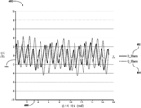
도 4는 본원에 기술되고 도시된 하나 이상의 실시예에 따라 DC 양이 제거된 D-고조파 및 Q-고조파의 플롯 그래프를 개략적으로 도시한다.
도 5는 본원에 기술되고 도시된 하나 이상의 실시예에 따라 다중 위상 전기 기계에 의해 생성된 비정현파 역기전력 전압을 보정하기 위한 방법의 흐름도를 개략적으로 도시한다.The embodiments described in the figures are illustrative and illustrative in nature and are not intended to limit the subject matter of the invention as defined by the claims. DETAILED DESCRIPTION The following detailed description of exemplary embodiments can be understood when read in conjunction with the drawings, wherein like structures are denoted by like reference numerals.
1 schematically illustrates an exemplary field oriented control system in accordance with one or more embodiments described herein.
2 schematically illustrates a microcontroller of the field oriented control system of FIG. 1 in accordance with one or more embodiments described and shown herein.
3 schematically illustrates a flowchart of a method for determining a model table by a correction algorithm in accordance with one or more embodiments described and shown herein.
4 schematically depicts a plot graph of D-harmonics and Q-harmonics with the DC amount removed in accordance with one or more embodiments described and shown herein.
5 schematically illustrates a flowchart of a method for correcting a non-sinusoidal back EMF voltage generated by a multi-phase electric machine in accordance with one or more embodiments described and shown herein.
도 1은 일반적으로 비정현파 역기전력(BEMF) 전압이 제공되는 DQ 평면에서 고조파 효과를 검출하고 제거하기 위한 시스템을 도시한다. 이 시스템은 필드 지향 제어기(field oriented controller, FOC)로서 다중 위상 전기 기계, PID 제어기, 및 마이크로 제어기를 포함한다. 마이크로 제어기는 회전자 플럭스 위치를 분석할 뿐만 아니라 BEMF 전압을 분석하여 EMF의 플럭스 벡터를 추출한다. 이러한 벡터는 동기식 다중 위상 전기 기계에 내재된 기하학적 구조 및 포화 효과로 인한 왜곡을 갖는다. BEMF 전압을 추출하고 회전자 플럭스 위치 결정을 아는 것의 결과로, 마이크로 제어기 내의 보정 알고리즘은, BEMF 벡터와 현재 회전 속도 및 전류를 포함하는 기계 작동점을 알고리즘으로 전송함으로써 이들 결함을 보정하고, 차례로 특정 작동점에 대해 DQ 프레임에서의 명령 전압을 생기게 한다. 이러한 명령 전압은 비정현파 BEMF 전압이 비정현파 전류를 생성하지 않도록 PI 제어기의 제어 출력에 삽입된다.Figure 1 illustrates a system for detecting and eliminating harmonic effects in the DQ plane, which is generally provided with a non-sinusoidal back electromotive force (BEMF) voltage. The system includes a multi-phase electric machine, a PID controller, and a microcontroller as a field oriented controller (FOC). The microcontroller not only analyzes the rotor flux position but also analyzes the BEMF voltage to extract the flux vector of the EMF. This vector has distortion due to the saturation effect and geometry inherent in synchronous multiphase electric machines. As a result of extracting the BEMF voltage and knowing the rotor flux positioning, the correction algorithm in the microcontroller compensates for these defects by sending a machine operating point containing the BEMF vector and the current rotational speed and current to the algorithm, which in turn Generates a command voltage in the DQ frame for the operating point. This command voltage is inserted into the control output of the PI controller so that the non-sinusoidal BEMF voltage does not produce non-sinusoidal current.
도 1을 참조하면, 예시적인 필드 지향 제어 회로의 개략도가 개략적으로 도시되어 있다. FOC 제어 시스템(10)은 교류 발전기와 같은 동기식 다중 위상 전기 기계(12)를 포함한다. 농형 회전자(squirrel cage rotor)를 갖는 비동기식 모터는 동기식 다중 위상 전기 기계(12)로 대체할 수 있음을 이해해야 한다. 다중 위상 전기 기계(12)는 (도시되지 않은) 고정자 및 회전자(14)를 포함한다. 전력단 인버터(22)는 다중 위상 전기 기계(12)에 통신 가능하게 결합되어 전력단 인버터(2)는 다중 위상 전기 기계(12)를 구동시킨다. Referring to FIG. 1, a schematic diagram of an exemplary field oriented control circuit is shown schematically. The FOC
여전히 도 1을 참조하면, FOC 제어 시스템(10)은 다중 위상 전기 기계(12)에 통신 가능하게 결합된 클라크 변환 모듈(Clarke transformation module)(44)을 더 포함한다. 클라크 변환 모듈(44)은 파크 변환 모듈(Park transformation module)(18)에 통신 가능하게 결합된다. 제1 비교기(54) 및 제2 비교기(56)와 마이크로 제어기(19)는 파크 변환기 모듈(18)에 통신 가능하게 결합된다. 필드 전류 신호(49)는 마이크로 제어기(19)에 통신 가능하게 결합된다. 제1 기준 신호(50)는 제1 비교기(54)에 통신 가능하게 결합되는 반면, 제2 기준 신호(52)는 제2 비교기(56)에 통신 가능하게 결합된다. 제1 비교기(54)는 제1 PI 제어기(30)에 통신 가능하게 결합된다. 제2 비교기(56)는 제2 PI 제어기(34)에 통신 가능하게 결합된다.Still referring to FIG. 1, the
여전히 도 1을 참조하면, 제1 PI 제어기(30)의 출력(27)은 제1 신호 보정 접합(35)에 통신 가능하게 결합되고, 제2 PI 제어기(34)의 출력(29)은 제2 신호 보정 접합(37)에 통신 가능하게 결합된다. 제1 피드 포워드 항(31) 또는 제1 명령 전압은 마이크로 제어기(19)로부터 제1 신호 보정 접합(35)에 통신 가능하게 결합된다. 제2 피드 포워드 항(33) 또는 제2 명령 전압은 마이크로 제어기(19)로부터 제2 신호 보정 접합(37)에 통신 가능하게 결합된다. 제1 신호 보정 접합(35)으로부터 제1 보정된 출력(28) 및 제2 신호 보정 접합(37)으로부터 제2 보정된 출력(32)은 역 파크 변환 모듈(inverse Park transformation module)(20)에 통신 가능하게 결합된다. 역 파크 변환 모듈(20)은 전력단 인버터(22)에 통신 가능하게 결합된다.Still referring to FIG. 1, the
이제 도 2를 참조하면, FOC 제어 시스템(10)의 마이크로 제어기(19)의 개략적인 회로도가 개략적으로 도시되어 있다. 도 2에 도시된 구성 요소는 메모리 모듈(72), 처리 디바이스(74), 입력 모듈(76), 통신 모듈(78) 및 데이터 저장 디바이스(80)를 포함한다. 구성 요소들은 통신 경로(82)에 의해 상호 연결된다.Referring now to FIG. 2, a schematic circuit diagram of the
여전히 도 2를 참조하면, 통신 경로(82)는, 예를 들어, 전도성 와이어, 전도성 트레이스, 광 도파관 등과 같은 신호를 전송할 수 있는 임의의 매체로부터 형성될 수 있다. 또한, 통신 경로(82)는 신호를 전송할 수 있는 매체의 조합으로부터 형성될 수 있다. 일 실시예에서, 통신 경로(82)는 프로세서, 메모리, 센서, 입력 디바이스, 출력 디바이스, 및 통신 디바이스와 같은 구성 요소로 전기 데이터 신호의 전송을 허용하도록 협력하는 전도성 트레이스, 전도성 와이어, 커넥터, 및 버스의 조합을 포함한다. "신호"라는 용어는 매체를 통해 이동할 수 있는 DC, AC, 사인파, 삼각파, 구형파, 진동 등과 같은 파형(예를 들어, 전기, 광학, 자기, 기계, 또는 전자기)을 의미한다. 통신 경로(82)는 FOC 제어 시스템(10)의 다양한 구성 요소들을 통신적으로 결합한다. 본원에서 사용되는 용어 "통신적으로 결합된"은 결합된 구성 요소가 예를 들어 전도성 매체를 통한 전기적 신호, 공기를 통한 전자기 신호, 광 도파관을 통한 광학 신호 등과 같은 데이터 신호를 다른 구성 요소와 서로 교환할 수 있음을 의미한다.Still referring to FIG. 2,
여전히 도 2를 참조하면, 처리 디바이스(74)는 기계 판독 가능한 명령을 실행할 수 있는 임의의 디바이스일 수 있다. 따라서, 처리 디바이스(74)는 제어기, 집적 회로, 마이크로칩, 컴퓨터, 또는 임의의 다른 컴퓨팅 디바이스일 수 있다. 처리 디바이스(74)는 통신 경로(82)에 의해 FOC 제어 시스템(10)의 다른 구성 요소와 통신 가능하게 결합된다. 도 2에 도시된 실시예는 단지 하나의 처리 디바이스(74)만을 포함하고, 다른 실시예는 통신 경로(82)에 의해 서로 통신적으로 결합된 다수의 프로세서를 포함할 수 있다.Still referring to FIG. 2, the
여전히 도 2를 참조하면, 입력 모듈(76)은 통신 경로(82)에 통신 가능하게 결합되고 처리 디바이스(74)에 통신 가능하게 결합된다. 입력 모듈(76)은 파크 변환 모듈(18), 필드 전류(49), 다중 위상 전기 기계(12) 및/또는 데이터 저장 디바이스(80)에 통신 가능하게 결합될 수 있다. 입력 모듈(76)은 회전자 위치 신호(16), 회전자 플럭스 성분 신호 Id(46), 회전자 토크 신호 Iq(48), 및/또는 필드 전류(49)를 수신할 수 있다. 입력 모듈은 신호(16, 46, 48, 49)를 처리 디바이스(76)에 의해 판독되는 전기 신호로 변환하거나, 및/또는 신호(16, 46, 48, 49)를 데이터 저장 디바이스(80)가 데이터를 저장하는데 사용할 수 있는 매체로 변환할 수 있으며, 이는 이하에서 기술한다.Still referring to FIG. 2,
여전히 도 2를 참조하면, FOC 제어 시스템(10)의 메모리 모듈(72)은 통신 경로(82)에 결합되고 처리 디바이스(74)에 통신 가능하게 결합된다. 메모리 모듈(72)은 휘발성 및/또는 비휘발성 컴퓨터 판독 가능한 매체로서 구성될 수 있으며, 그에 따라 (SRAM, DRAM, 및/또는 다른 유형의 랜덤 액세스 메모리를 포함하는) 랜덤 액세스 메모리, 읽기 전용 메모리(ROM), 플래시 메모리, 레지스터, 콤팩트 디스크(CD), 디지털 다기능 디스크(digital versatile discs, DVD), 및/또는 기계 판독 가능한 명령을 저장할 수 있는 다른 유형의 저장 구성 요소를 포함할 수 있어서, 기계 판독 가능한 명령이 처리 디바이스(74)에 의해 액세스되고 실행될 수 있다. 기계 판독 가능한 명령은, 예를 들어, 기계 판독 가능한 명령으로 컴파일 또는 어셈블링될 수 있고 메모리 모듈(72)에 저장될 수 있는, 프로세서에 의해 직접 실행될 수 있는 기계 언어, 또는 어셈블리 언어, 객체-지향 프로그래밍(object-oriented programming, OOP), 스크립팅 언어, 마이크로 코드 등과 같은 임의의 세대의 임의의 프로그래밍 언어로 작성된 로직 또는 알고리즘(들)을 포함할 수 있다. 대안으로, 기계 판독 가능한 명령은 필드 프로그램 가능한 게이트 어레이(field-programmable gate array, FPGA) 구성 또는 주문형 집적 회로(application-specific integrated circuit, ASIC) 또는 그들의 균등물을 통해 구현되는 로직과 같은 하드웨어 기술 언어(hardware description language, HDL)로 기록될 수 있다. 따라서, 본원에 기술된 기능은 미리 프로그래밍된 하드웨어 요소, 또는 하드웨어 및 소프트웨어 구성 요소의 조합으로서 임의의 종래의 컴퓨터 프로그래밍 언어로 구현될 수 있다. 메모리 모듈(72)은 처리 디바이스(74)에 의해 실행되는 경우 처리 디바이스(74)로 하여금 도 3과 관련하여 본원에 기술된 프로세스와 같은 다양한 프로세스를 완료하게 하는 메모리 모듈 상의 하나 이상의 프로그래밍 명령을 포함할 수 있다.Still referring to FIG. 2, the
여전히 도 2를 참조하면, 메모리 모듈(72)에 저장된 프로그래밍 명령은 복수의 소프트웨어 로직 모듈(72a)로서 구현될 수 있으며, 여기서 각 로직 모듈은 하나 이상의 작업을 완료하기 위한 프로그래밍 명령을 제공한다. 예를 들어, 도 2는 본원에서 도시되고 기술된 하나 이상의 실시예들에 따른 예시적인 로직 구성 요소(72a)를 포함하는 메모리 모듈(72)을 개략적으로 도시한다. 도 2에 도시된 바와 같이, 메모리 모듈(72)은 예를 들어, 모델 테이블(72b) 및 보정 알고리즘(72c)과 같은 다양한 처리 로직을 저장하도록 구성될 수 있다. 모델 테이블(72b)은 측정 데이터를 포함하는 룩업 테이블을 포함할 수 있으며, 이는 이하에서 더 상세히 기술될 것이다. 모델 테이블(72b)은, 이하에서 후술하는 바와 같이, 회전자(14)의 위치와 적용 가능하다면 필드 전류(49)에 기초하여 2개의 전압 값을 제공하도록 구성될 수 있다. 또한, 보정 알고리즘(72c)은 측정된 데이터를 사용하기 보다는 이들 값을 계산하는 표현 또는 모델을 포함할 수 있거나, 또는 이러한 값을 판독하여 모델 테이블(72b)을 생성하고, 적절한 보정이 요구되는 경우에 모델 테이블(72b)을 참조하도록 구성될 수 있음을 이해해야 할 것이다. 이와 같이, 보정 알고리즘(72c)은 이하에서 더 상세히 논의되는 바와 같이, BEMF 벡터(98, 100)를 결정하고, 계산하며, 및/또는 보정하기 위한 운영 시스템 및/또는 다른 소프트웨어를 포함할 수 있다. Still referring to FIG. 2, programming instructions stored in
여전히 도 2를 참조하면, 통신 모듈(78)은 통신 경로(82)에 결합되고 처리 디바이스(74)에 통신 가능하게 결합된다. 통신 모듈(78)은 네트워크를 통해 데이터를 전송 및/또는 수신할 수 있는 임의의 디바이스일 수 있다. 따라서, 통신 모듈(78)은 임의의 유선 또는 무선 통신을 보내거나 및/또는 수신하기 위한 통신 트랜시버를 포함할 수 있다. 예를 들어, 통신 모듈(78)은 다른 네트워크 및/또는 디바이스와 통신하기 위한 안테나, 모뎀, LAN 포트, Wi-Fi 카드, WiMax 카드, 모바일 통신 하드웨어, 근거리 통신 하드웨어, 위성 통신 하드웨어, 및/또는 임의의 유선 또는 무선 하드웨어를 포함할 수 있다. 일 실시예에서, 통신 모듈(78)은 블루투스® 무선 통신 프로토콜에 따라 동작하도록 구성된 하드웨어를 포함할 수 있다. 일부 실시예에서, 통신 모듈(78)은 블루투스® 4.0 통신 프로토콜에 따라 무선 신호를 전송 및/또는 수신하도록 구성된 무선 통신 모듈일 수 있다. 그러한 실시예에서, 통신 모듈(78)은 다른 에너지 효율이 낮은 무선 통신 프로토콜보다 적은 에너지를 사용하여 신호를 전송하고 수신할 수 있다. 그러나, 일부 실시예에서, 통신 모듈(78)은 블루투스® 4.0 통신 프로토콜 이외의 무선 통신 프로토콜에 따라 무선 신호를 전송 및/또는 수신하도록 구성된다. 일부 실시예는 유선 네트워크를 통해 데이터를 전송 및/또는 수신하기 위한 유선 통신 모듈을 포함하는 실시예와 같은 통신 모듈(78)을 포함하지 않을 수 있다.Still referring to FIG. 2,
여전히 도 2를 참조하면, 일반적으로 저장 매체일 수 있는 데이터 저장 디바이스(80)는 수신되고 및/또는 생성된 데이터를 저장하기 위한 하나 이상의 데이터 저장소를 포함할 수 있다. 데이터 저장 디바이스(80)는 하드 디스크 드라이브(hard disk drive, HDD), 메모리, 제거 가능한 저장 장치 등을 포함하지만, 이에 한정되지는 않는 임의의 물리적 저장 매체일 수 있다. 데이터 저장 디바이스(80)는 로컬 디바이스로 도시되어 있지만, 데이터 저장 디바이스(80)는 예를 들어, 서버 컴퓨팅 디바이스 등과 같은 원격 저장 디바이스일 수 있음을 이해해야 한다. Still referring to FIG. 2, a
여전히 도 2를 참조하면, FOC 제어 시스템(10)의 저장 디바이스(예를 들어, 데이터 저장 디바이스(80)) 내에 포함된 다양한 데이터의 블록도가 본원에 도시되고 기술된다. 데이터 저장 디바이스(80)는, 예를 들어, 회전자 위치 데이터(84), 필드 전류 데이터(85), 회전자 플럭스 위치 데이터 Id(86), 회전자 토크 데이터 Iq(88), 전류 벡터 데이터(90), 회전자 플럭스 BEMF Ud 데이터(92), 회전자 토크 BEMF Uq 데이터(84), 및/또는 데이터 베이스 데이터(96)를 포함할 수 있다.Still referring to FIG. 2, a block diagram of various data contained within a storage device (eg, data storage device 80) of the
도 2를 참조하면서 도 1을 다시 참조하면, 회전자 위치 데이터(84)는 다중 위상 전기 기계(12)에서 생성되고 마이크로 제어기(19)에 전송된 회전자 위치(16)일 수 있다. 필드 전류 데이터(85)는 회전자(14)의 필드 전류(49), 또는 각도일 수 있다. 회전자 플럭스 위치 데이터 Id(86)와 회전자 토크 데이터 Iq(88)는 각각 46 및 48로 도시된 파크 변환 모듈(18)로부터 생성된 신호일 수 있다. 전류 벡터 데이터(90)는 실제 회전자 플럭스 위치 데이터 Id(86)와 회전자 토크 데이터 Iq(88)의 합일 수 있다. 회전자 플럭스 BEMF Ud 데이터(92)는 98로 도시된 회전자 플럭스 BEMF 벡터로부터, 또는 그와 관련된 데이터를 저장할 수 있고, 회전자 플럭스 BEMF Ud 데이터(92)는 100으로 도시된 토크 BEMF 벡터로부터, 또는 그와 관련된 데이터를 저장할 수 있고, 도 3의 방법과 이하의 도 5에 더 논의된다.Referring again to FIG. 1 with reference to FIG. 2, the
도 2를 참조하면, 데이터 베이스(96)는, 이에 한정되지는 않지만, 예를 들어, 보다 상세하게 기술될 D 고조파, Q 고조파, 관찰 그래프 및/또는 그와 유사한 것들과 같은 모델 테이블(72b) 내에 포함된 데이터를 포함할 수 있다. 일부 실시예에서, 데이터 베이스 데이터(96)는 모델 테이블(72b)과 함께 작동할 수 있어서, 데이터 베이스 데이터(96)에 저장된 D, Q 고조파는 보정 알고리즘(72c)에 의해 분석될 수 있고, 모델 테이블(72b)을 채우도록 계산될 수 있어서, 회전자 위치(16) 및 적용 가능한 경우에는 필드 전류(49)에 기초하여, 마이크로 제어기(19)의 보정 알고리즘(72c)은 이하에 더 상세히 기술되는 바와 같이 각각의 회전자 위치에서 D 및 Q 고조파 값의 정규화된 값을 제공한다.With reference to FIG. 2,
도 2에 기술된 구성 요소는 단지 예시적인 것이고, 본 개시의 범위를 한정하려는 의도는 아니라는 것이 이해되어야 한다. 보다 구체적으로, 도 2의 구성 요소는 FOC 제어 시스템(10) 내에 상주하는 것으로 도시되어 있지만, 이는 제한적인 예시가 아니다. 일부 실시예에서, 하나 이상의 구성 요소는 FOC 제어 시스템(10)의 외부에 상주할 수 있다. It is to be understood that the components described in FIG. 2 are merely exemplary and are not intended to limit the scope of the present disclosure. More specifically, although the components of FIG. 2 are shown to reside within the
다시 도 1을 참조하면, 시스템 작동이 기술될 것이다. 작동 시, FOC 제어 시스템(10)은 다중 위상 전기 기계(12) 내의 회전자의 플럭스 위치와 같이 회전자(14)를 직접 모니터링하도록 구성된다. 이와 같이, 회전자 위치(16)는 파크 변환 모듈(18) 및 역 파크 변환 모듈(20)로 직접 전송된다. 전력단 인버터(22)는 이하에 더 상세히 기술되는 바와 같이 역 파크 모듈(20)로부터 수신된 보정된 입력에 기초하여 다중 위상 전기 기계(12)를 구동한다. 역 파크 변환 모듈(20)은 제1 신호 보정 접합(35)으로부터 28로 도시된, 보정된 플럭스 신호 Ud를 수신한다. 역 파크 변환 모듈(20)은 제2 신호 보정 접합(37)으로부터 32로 도시된 보정된 토크 신호 Uq를 수신한다. 플럭스 보정된 신호 Ud(28), 토크 보정된 신호 Uq, 제1 신호 보정 접합(35) 및 제2 신호 보정 접합(37)은 이하에서 더 상세히 기술될 것이다.Referring again to FIG. 1, system operation will be described. In operation, the
여전히 도 1을 참조하면, 3상 AC 모터로 도시된 다중 위상 전기 기계(12)는 대체로 3개의 120도의 공간적으로 변위된 정현파 전압을 3개의 고정자에 인가할 수 있다. 따라서, 각 위상마다 별도의 사인파와 별도의 벡터가 있을 수 있다. FOC 제어 시스템(10)은 일반적으로 벡터 제어 방식으로 알려져 있다. 즉, FOC 제어 시스템(10)은 특정 벡터로 표현되는 고정자 전류를 제어하도록 구성된다. 도시된 바와 같이, 다중 위상 전기 기계(12)는 각각 38, 40, 및 42에 도시된 바와 같이 3상 출력인, U상 전류(Iu), V상 전류(Iv), W상 전류(Iw)를 전송한다. 회전자 속도 및 3상 시간에 기인한 전류 Iu(38), Iv(40), 및 Iw(42)는 다중 위상 전기 기계(12)로부터 클라크 변환 모듈(44)로 전송된다. Still referring to FIG. 1, a multi-phase
여전히 도 1을 참조하면, 클라크 변환 모듈(44)은 일반적으로 2개의 좌표 시간 변형 시스템(α, β)을 출력하는 것으로 알려져 있다. 구체적으로, 클라크 변환 모듈의 2개의 좌표 시간 변형 시스템(α, β)은 여전히 시간과 속도에 의존하는 2차원 직교 시스템이다. 이와 같이, 각각 38, 40, 42에 도시된 전류 Iu, Iv, 및 Iw는 2개의 좌표 시간 변환 시스템(α, β)으로 변환된다. Still referring to FIG. 1, the
여전히 도 1을 참조하면, 변환된 2개의 좌표 시간 변환 시스템(α, β)은 파크 변환 모듈(18)에 대한 입력으로서 파크 변환 모듈(18)에 전송된다. 파크 변환 모듈(18)은 d, q 회전 기준 프레임에서 2상 직교 시스템(α, β)을 수정한다는 것을 이해해야 한다. 이와 같이, d 좌표는 전류 벡터에 대한 회전자 플럭스 성분과 정렬될 수 있고, q 좌표는 전류 벡터의 토크 성분과 정렬될 수 있다. 따라서, d, q 성분은 전류 벡터(α, β)에 의존한다. 이와 같이, 파크 변환 모듈(18)은 d, q 회전 기준 프레임에서 전류를 제공한다. 따라서, 각각 46, 48로 도시된 회전자 플럭스 성분 Id 및 회전자 토크 성분 Iq은 파크 변환 모듈(18)로부터 전송된다.Still referring to FIG. 1, the transformed two coordinate time conversion systems α and β are transmitted to the
여전히 도 1을 참조하면, DQ 평면에서, FOC 제어 시스템(10)은 제1 PI 제어기(30) 및 제2 PI 제어기(34)를 사용하여 벡터를 제어하기 위해 벡터를 비교할 수 있다. FOC 제어 시스템(10)에 대해 벡터를 제어하기 위해, FOC 제어 시스템(10)은 입력 기준으로서 두 상수, 회전자 플럭스 성분 Id(46) 및 회전자 토크 성분 Iq(48)을 요구할 수 있다. 당업계에 일반적으로 공지되고 이해되는 바와 같이, FOC 제어 시스템(10)은 일반적으로 정상 상태 및 과도 작업 모드 모두에서 정확하게 제어하기 위해 이러한 투영에 기초한다. Still referring to FIG. 1, in the DQ plane, the
여전히 도 1을 참조하면, 회전자 플럭스 기준 Id(50) 또는 플럭스 명령, 및 회전자 토크 기준 Iq(52) 또는 토크 명령은, 이에 제한되지는 않지만 예를 들어, (도시되지 않은) 속도 조정기, 영구 자석 동기식 모터와 같은 (도시되지 않은) 동기식 모터 각각으로부터의 출력으로서 FOC 제어 시스템(10)에 입력될 수 있다. 회전자 플럭스 성분 Id(46)은 제1 비교기(54)에서 회전자 플럭스 기준 Id(50)과 비교된다. 회전자 토크 성분 Iq(48)은 제2 비교기(56)에서 회전자 토크 기준 Iq(52)과 비교된다.Still referring to FIG. 1, the rotor flux reference I d 50 or flux command, and the rotor torque reference I q 52 or torque command may include, but are not limited to, for example, speed (not shown). It can be input to the
여전히 도 1을 참조하면, 일단 회전자 플럭스 성분 Id(46)이 회전자 플럭스 기준 Id(50)과 비교되면, Id 에러(58)가 결정되고, 제1 PI 제어기(30)로 전송된다. Id 에러(58)는 회전자 플럭스 기준 Id(50)과 회전자 플럭스 성분 Id(46) 간의 차이이다. 이와 유사하게, 일단 회전자 토크 성분 Iq(48)이 회전자 토크 기준 Iq(52)과 비교되면, Iq 에러(60)가 결정되고, 제2 PI 제어기(34)로 전송된다. Iq 에러(60)는, 회전자 토크 기준 Iq(52)과 회전자 토크 성분 Iq(48) 간의 차이이다.Still referring to FIG. 1, once the rotor flux component I d 46 is compared to the rotor flux reference I d 50, an
여전히 도 1을 참조하면, 제1 PI 제어기(30) 및 제2 PI 제어기(34)는 일정한 기준을 사용하여 토크 및 플럭스 피드백을 원하는 값으로 조정한다. 즉, PI 제어기(30, 34)의 비례 부분은 설정점과 측정된 출력 사이의 오류를 보정하려고 시도할 것이다. 적분 부분은 시간에 따른 에러를 누적하여 에러에 보정을 적용한다. 미분 부분은 시스템의 속도에 비례하여 미분기의 출력이 다중 위상 전기 기계(12)를 느리게 하도록 적용된다. 이와 같이, 제1 PI 제어기(30) 및 제2 PI 제어기(34)는 피드백 시스템의 일부로서 모터 전류를 조정하는 프로세스를 제어하는 기능을 한다.Still referring to FIG. 1, the
종래의 시스템에서, 제1 PI 제어기(30)의 출력, 27로 도시된 제어된 플럭스 성분 신호 Ud 및 제2 PI 제어기(34)의 출력, 29로 도시된 제어된 토크 성분 신호 Uq는 (도시되지는 않았지만) 직접적으로 역 파크 변환 모듈(20)로 전송된다. 그러나, 일반적으로 알려진 바와 같이, FOC 제어 시스템(10)은 전압 및 전류가 순수한 사인파인 것으로 가정하기 때문에 적절히 기능한다. 전압 및 전류가 순수한 사인파가 아닌 경우, FOC 제어 시스템(10)은 모터 전류를 조정하는데 어려움을 가진다. 다중 위상 전기 기계에서는 비정현파 BEMF 전압이 생기는 경향이 있다. 따라서, 비정현파 BEMF 전압은 제어 알고리즘에 대한 제어 가능성 문제를 만든다. 비정현파 BEMF 전압에 대항하기 위해, 비정현파 BEMF 전압의 DQ 평면에서의 영향을 예측하고 제거할 수 있는 보정 알고리즘(72c)(도 2)을 갖는 마이크로 제어기(19)가 이하에서 기술될 것이다.In a conventional system, the output of the
BEMF에서의 고조파는 (도시되지 않은) 비정현파 자속쇄교수을 생성하는 회전자(14)의 톱니의 기하학적 구조에 기인할 수 있고, 회전하는 경우에 이러한 쇄교는 (도시되지 않은) 고정자 권선에서 전압을 유도한다는 것이 이해되어야 한다. 패러데이의 유도 법칙에 따르면, 유도된 전압은 플럭스의 변화율에 비례한다는 것이 더 이해되어야 한다.The harmonics in the BEMF can be attributed to the geometry of the teeth of the
따라서, 속도에 선형으로 고조파 스케일을 포함한 모든 유도 전압은 플럭스의 변화율에 비례한다. 전류 고조파의 또 다른 알려진 원인으로 고정자 인덕턴스가 필드 전류(49)에 따라 변하는 경우가 있다. 이와 같이, 유도 전압은 기계 내의 자기 저항 경로에 내장된 플럭스 ?문일 수 있으며, 이는 고정자 Ld 및 Lq를 또한 결정하는 동일한 자기 저항 경로일 수 있다. 따라서, BEMF가 정현파가 아닌 경우, 인덕턴스는 일정하지 않을 것이다. 고조파를 적절히 처리하려면, BEMF와 변화하는 인덕턴스가 모두 피드 포워드(fed forward) 되어야한다. 인덕턴스를 변경함으로써 생성된 고조파는 다음의 식에 기인한다: ![]()
![]()
따라서, 정현파로 의도된 전류일지라도, 인덕턴스가 변한다면, 전류 정현파를 유지하기 위해 인가된 전압은 정현파가 아닐 수 있다. 따라서, 인덕턴스가 변한다면, 전류 정현파를 유지하기 위해 실제 전압에 기초하여 직각으로 수직 전압 벡터가 인가될 수 있다. 인덕턴스의 전압과 전류는 전압이 전류를 리드하도록 90도 떨어져있다. 따라서, 벡터에서, Iq 전류는 90도 각도 차이로 인해 d의 전압 벡터를 필요로 한다. 결과적으로, BEMF 및 변화하는 인덕턴스가 FOC 제어 시스템(10)으로 피드 포워드될 필요가 있을 수 있다.Thus, even if the current is intended to be sinusoidal, if the inductance changes, the voltage applied to maintain the current sinusoid may not be sinusoidal. Thus, if the inductance changes, a vertical voltage vector can be applied at right angles based on the actual voltage to maintain the current sine wave. The voltage and current of the inductance are 90 degrees apart so that the voltage leads the current. Thus, in the vector, Iq current requires a voltage vector of d due to the 90 degree angle difference. As a result, BEMF and varying inductance may need to be fed forward to the
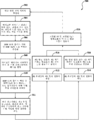
이제 도 3을 참조하면, 보정 알고리즘(72c)에 의해 모델 테이블(72b)을 결정하는 방법(300)이 기술될 것이다. 모델 테이블(72b) 및 보정 알고리즘(72c)은 FOC 제어 시스템(10)에 제1 피드 포워드 항(31) 및 제2 피드 포워드 항(33)으로서 삽입되는 보정 명령 전압을 설정한다. 302에서, 모델 테이블(76b)을 설정하기 위해, 하나의 전기적 사이클의 BEMF(98, 100)은 알려진 회전 속도로 캡쳐된다. BEMF(98, 100)은 3가지 주요 소스: (1) Ansys Maxwell과 같은 도구로부터의 시뮬레이션 데이터; (2) 단일 기계로부터 직접 측정; (3) 라인 테스트의 시스템 끝/교정 프로세스(system end of line test/calibration process)의 일부로서 직접 측정;으로부터 측정될 수 있다는 것을 이해해야 하지만, 이에 제한되지는 않는다.Referring now to FIG. 3, a
도 3을 참조하면, 304에서, BEMF(98, 100)는 고조파 충실도를 캡쳐하기에 충분히 큰 샘플 속도로 필드 전류(49)와 함께 캡쳐될 수 있다. 더욱이, 만약 다중 위상 전기 기계(12)가 클로 폴(claw pole) 교류 발전기에서 보여지는 것과 같이 외부적으로 여기되고(excited), 필드 전류(49)가 포화 효과와 같이 고조파 성분에 상당한 영향을 미친다면, 여러 역 EMF 샘플이 예상된 필드 전류(49)의 범위에 걸쳐 캡쳐될 수 있다. 306에서, 일단 다중 위상 역 EMF가 캡쳐되고 저장되면, DQ0 변환을 수행하기 위해 관련된 위치 데이터를 사용하고, 이는 310에서 DQ 기준 프레임에서 고조파를 드러낸다. 그 후, “DQ 수량”은 312에서 기계 기본 주파수의 진폭을 나타내므로 제거될 수 있다. 결과 그래프(400)(도 4)는 보정 알고리즘(72c)에 삽입되는 D 고조파 및 Q 고조파의 예시적인 관찰 플롯이어서, 단계 314에서 모델 테이블(72b)은 제1 피드 포워드 항(31)과 제2 피드 포워드 항(33)을 플로팅함으로써 생성될 수 있으며, 이는 이하에서 더 상세히 기술된다. 모델 테이블은 또한 회전자 위치에 기초하여 D 고조파 및/또는 Q 고조파에 대한 보정을 상관시킬 수 있다.Referring to FIG. 3, at 304,
여전히 도 3을 참조하면서 이제 도 4를 참조하면, “DC 수량”이 제거된 D 고조파(402)와 Q 고조파(404)의 그래프(400)가 개략적으로 도시되어 있다. 그래프의 가로 좌표는 볼트의 진폭(406)을 나타내고, -10 볼트 내지 +10 볼트의 범위로 도시되어 있지만, 이는 예시일 뿐이며 이로 한정하는 것은 아니다. 세로 좌표는 라디안으로 전기 각도(408)를 나타낸다. 그래프는 0 라디안에서 18 라디안으로 표시되지만, 이는 단지 예시일 뿐이며 이에 한정되어서는 안된다. 도시된 바와 같이, D-고조파(402)는 실선으로 표시되고 Q-고조파(404)는 점선으로 도시된다. D-고조파와 Q-고조파는 모두 양에서 음으로 가는 제로 진폭 라인을 중심으로 진동(oscillate)한다. 또한, Q-고조파는 D-고조파보다 큰 진폭을 가질 수 있다. 또한, Q-고조파와 D-고조파는 상술한 바와 같이, 서로 90도 오프셋될 수 있다.Referring now to FIG. 4 while still referring to FIG. 3, there is schematically shown a graph 400 of
도 3 및 도 4를 참조하고, 전술한 바와 같이, 모델 테이블(72b)은 FOC 알고리즘에 입력된 D-고조파(402) 및 Q-고조파(404)로 채워져서, 그래프(400)는 고조파 왜곡에 대한 관찰 모델 그래프이다. 즉, 이러한 특정 다중 위상 전기 기계(12)와 미리 결정된 공차 내의 모든 다른 다중 위상 전기 기계(12)에 대해, 모델 테이블(72b)은 보정 알고리즘(72c)에 입력된 D-고조파(402) 및 Q-고조파(404)로 채워져서, (도 1의) 회전자 위치(16) 및/또는 필드 전류(49), 또는 (도 1의) 회전자 각도에 기초하여, 적절한 피드 포워드 항 또는 명령 전압이 FOC 제어 시스템(10)에 삽입된다.3 and 4, and as described above, the model table 72b is populated with the D-
보정 알고리즘(72c)은 제1 피드 포워드 항(31) 또는 제1 명령 전압(D-고조파 보정), 및 제2 피드 포워드 항(33) 또는 제2 명령 전압(Q-고조파 보정)으로 모델 테이블(72b)을 이하의 식을 사용하여 계산하고, 채운다:The

여기서, FOC 제어 시스템(10)이 디지털 공간에서 숫자 변환을 얻는 것을 고려하면서, 스칼라(V) 및 스칼라(I)는, 전류, 인덕턴스, 및/또는 이와 유사한 것과 같은 표현에서 계산된 물리량을 마이크로 제어기(19)에서 작동하는 값으로 스케일링하기 위한 값과 동일하다. 더욱이, Here, while taking into account that the
![]()
![]()
여기서, Rpm은 회전 속도(차등 위치 벡터)와 동일하고, ![]()
![]()
![]()
![]()
다중 위상 전기 기계(12)의 전기적 주파수는 이하의 식으로 계산된다:The electrical frequency of the multiphase

마지막으로, ![]()
![]()
모델 테이블(72b), 룩업 테이블, 모델, 방정식 등 및 보정 알고리즘(72c)은 회전자(14)의 위치에 기초하여 회전자 위치(16) 및 필드 전류(49)로 전송되는 BEMF Ud(98) 및 BEMF Uq(100)의 2개의 전압 값을 제공함으로써 기능할 수 있다. 모델 테이블(72b)은 각각의 회전자 위치에서 정규화된 D 및 Q 고조파의 값을 제공할 수 있다. 이와 같이, 모델 테이블(72b)은 그 각도에서의 D 및 Q 고조파의 진폭을 나타내는 2개의 숫자와 상관되는 회전자 위치(및 적용 가능한 경우에는 필드 전류)에 피드될 수 있으며, 이는 이하에서 상세히 기술될 것이다. 이와 같이, 마이크로 제어기(19)는 신호 보정 접점(35, 37)에서 PI 제어기 출력(27, 29)에 대해 적절한 피드 포워드 항(31, 33)을 FOC 제어 시스템(10)에 제공한다. 결과적으로, 고조파를 제어하기 위한 시도로 PI 제어기 출력(27, 29)을 사용하는 종래의 방법이 필요하지 않아서, FOC 루프가 고조파에 대한 보상이 가능해야할 필요가 없다.The model table 72b, lookup table, model, equations, etc., and the
이제 도 5를 참조하면, 다중 위상 전기 기계(12)에 의해 생성된 비정현파 BEMF 전압을 보정하기 위한 방법(500)이 기술될 것이다. 상술한 바와 같이, 입력 모듈(76)은 마이크로 제어기(19)로 복수의 신호를 수신한다. 502에서, 다중 위상 전기 기계(12)가 활성화되는 경우, 504에서, 마이크로 제어기(19)는 회전자 위치(16), 회전자 플럭스 성분 Id(46), 회전자 토크 신호 Iq(48), 및/또는 필드 전류(49), 또는 회전자의 각도(14)를 분석한다. 단계 506에서, BEMF Ud의 플럭스 벡터(98) 및 BEMF Uq의 토크 벡터(100)는 추출되어서, 다중 위상 전기 기계(12)의 회전자(14)의 회전 및 다중 위상 전기 기계(12)의 회전자 속도를 표시한다.Referring now to FIG. 5, a
도 5를 참조하면, 마이크로 제어기(19)는, 508에서, 기하학적 구조 및 포화 효과로부터의 왜곡을 결정한다. 510에서, BEMF Ud의 플럭스 벡터(98) 및 BEMF Uq의 토크 벡터(100)는, 보정 알고리즘(72c)에 의해 모델 테이블(72b)과 비교된다. 511에서, 보정 알고리즘(72c)은, 전류 D 및 Q 고조파, 회전자 위치(16), 및 적용 가능하다면 필드 전류(49)에 기초하여 전류 D 및 Q 고조파(402, 404)(도 4)에 대한 적절한 명령 전압을 결정한다. 이에 따라, 512에서 모델 테이블(72b)은 BEMF Ud의 플럭스 벡터(98) 및 회전자 위치(16)를 상관시키는 DQ 프레임에서의 제1 명령 전압, 및 BEMF Uq의 토크 벡터(100)를 상관시키는 DQ 프레임에서의 제2 명령 전압을 제공한다. 512에서, DQ 프레임의 제1 명령 전압 값이 생성된다. 514에서, DQ 프레임의 제2 명령 전압이 생성된다.Referring to FIG. 5, the
516에서, BEMF Ud의 플럭스 벡터(98)에 대한 제1 명령 전압 값은 제1 피드 포워드 항(31)으로서 제1 신호 보정 접점(35)으로 삽입된다. 제1 피드 포워드 항(31)은 제1 PI 제어기(30)의 제어된 플럭스 성분 출력 Ud(27)을 보정한다. 518에서, BEMF Uq의 토크 벡터(100)에 대한 제2 명령 전압 값은 제2 피드 포워드 항(33)으로서 제2 신호 보정 접점(37)으로 삽입된다. 제2 피드 포워드 항(33)은 제2 PI 제어기(34)의 제어된 토크 성분 출력 Uq을 보정한다. 520에서, 보정된 Ud(28) 및 보정된 Uq(32)는 역 파크 변환 모듈(20)로 전송된다. 502에서, 고조파를 결정하고, 고조파 및 회전자 위치에 기초하여 값을 결정하기 위해 모델 테이블(72b)을 사용하고, 적절한 피드 포워드 항(31, 33)을 전송하는 보정 알고리즘(72c)의 이러한 프로세스는 다중 위상 전기 기계(12)가 활성화되는 동안 반복된다.At 516, the first command voltage value for
여전히 도 5를 참조하면, 제1 피드 포워드 항(31) 및 제2 피드 포워드 항(33)은 BEMF 전압(Ud 및 Uq)이 다중 위상 전기 기계(12)의 작동 범위에 걸쳐 비정현파 전류를 생성하는 것을 방지하여 DQ 평면에서 PI 제어기(30, 34) 루프에 대한 제어량을 DC 값으로 유지한다.Still referring to FIG. 5, the first feed
도 5에 도시된 프로세스는 단지 단일 방향인 것이 이해되어야만 한다. 그러나, 이는 단지 예시적으로 프로그램의 루프 또는 단일 반복을 설명하기 위한 목적이다. 프로세스의 연속적인 루프는 복수의 반복을 통한 것임을 이해해야만 한다. 이들은 단지 모델 테이블(72b)을 사용하는 예시일 뿐이며, 상술한 바와 같이, FOC 제어 시스템(10)에서 고조파를 보정하고 결정하는 다른 방법이 있다는 것을 이해해야만 한다.It should be understood that the process shown in FIG. 5 is only unidirectional. However, this is merely for illustrative purposes only to illustrate loops or single iterations of a program. It should be understood that a continuous loop of processes is through multiple iterations. These are merely examples using the model table 72b, and it should be understood that there are other ways to correct and determine harmonics in the
특정 실시에들이 본원에 도시되고 기술되어 있지만, 청구된 발명의 주제의 사상 및 범위를 벗어나지 않으면서 다양한 다른 변경 및 수정이 이루어질 수 있음을 이해해야만 한다. 또한, 청구된 발명의 주제의 다양한 양태가 본원에서 기술되었지만, 이러한 양태는 조합하여 이용되어야만 할 필요는 없다. 따라서, 첨부된 청구 범위는 청구된 발명의 주제의 범위 내에 있는 모든 변경 및 수정을 포함하는 것으로 의도된다.While specific embodiments have been shown and described herein, it should be understood that various other changes and modifications can be made without departing from the spirit and scope of the claimed subject matter. In addition, while various aspects of the claimed subject matter have been described herein, these aspects need not be used in combination. Accordingly, the appended claims are intended to cover all such alterations and modifications as fall within the scope of the claimed subject matter.
Claims (16)
한 쌍의 PID(proportional-integral-derivative) 제어기로서, 상기 한 쌍의 PID 제어기는 상기 제1 전기 출력을 수신하고, 제2 전기 출력을 가지는, 한 쌍의 PID 제어기; 및
모델 테이블 및 보정 알고리즘을 가지는 마이크로 제어기로서, 상기 마이크로 제어기는 상기 전기 기계로부터 기계 전류 벡터를 수신하고, 상기 제1 전기 출력을 수신하도록 구성된, 마이크로 제어기를 포함하고,
상기 마이크로 제어기는 상기 기계 전류 벡터에 기초하여 상기 모델 테이블을 상기 제1 전기 출력과 상관시키고, 각각 보정 전압을 가지는 제1 피드 포워드 항(a first feed forward term) 및 제2 피드 포워드 항(a second feed forward term)을 전송하고,
상기 제1 피드 포워드 항 및 상기 제2 피드 포워드 항은 상기 한 쌍의 PID 제어기의 제2 전기 출력에 삽입되어서, 상기 마이크로 제어기에 의해 상기 제2 전기 출력에 전송된 보정 전압은 상기 전기 기계의 고조파를 제거하는,
전기 기계로부터의 출력에서 고조파 왜곡을 보정하기 위한 시스템.A system for correcting harmonic distortion at an output from an electrical machine producing a first electrical output, the system comprising:
A pair of proportional-integral-derivative (PID) controllers, the pair of PID controllers receiving the first electrical output and having a second electrical output; And
A microcontroller having a model table and a calibration algorithm, the microcontroller comprising a microcontroller configured to receive a machine current vector from the electrical machine and to receive the first electrical output,
The microcontroller correlates the model table with the first electrical output based on the machine current vector, and includes a first feed forward term and a second feed forward term each having a correction voltage. feed forward term),
The first feed forward term and the second feed forward term are inserted into a second electrical output of the pair of PID controllers such that a correction voltage sent by the microcontroller to the second electrical output is a harmonic of the electrical machine. To remove,
A system for correcting harmonic distortion at the output from an electrical machine.
상기 전기 기계는 회전자를 포함하고, 상기 회전자는 위치 출력을 가지며, 상기 마이크로 제어기는 상기 위치 출력을 상기 모델 테이블의 값과 상관시키며, 상기 보정 알고리즘은 상기 제1 피드 포워드 항 및 상기 제2 피드 포워드 항을 전송하는,
전기 기계로부터의 출력에서 고조파 왜곡을 보정하기 위한 시스템.The method of claim 1,
The electric machine includes a rotor, the rotor having a position output, the microcontroller correlates the position output with a value of the model table, and the correction algorithm is configured to include the first feed forward term and the second feed. Send forward terms,
A system for correcting harmonic distortion at the output from an electrical machine.
상기 전기 기계는 필드 전류를 전송하고, 상기 마이크로 제어기는 상기 필드 전류와 상기 위치 출력을 상관시켜서, 대응하는 상기 모델 테이블의 값은 보정 알고리즘에 의해 상기 제1 피드 포워드 항 및 상기 제2 피드 포워드 항으로서 전송될 수 있는,
전기 기계로부터의 출력에서 고조파 왜곡을 보정하기 위한 시스템.The method of claim 2,
The electric machine transmits a field current, and the microcontroller correlates the field current with the position output such that the value of the corresponding model table is determined by a correction algorithm by the first feed forward term and the second feed forward term. Which can be transmitted as
A system for correcting harmonic distortion at the output from an electrical machine.
상기 모델 테이블은 룩업 테이블인,
전기 기계로부터의 출력에서 고조파 왜곡을 보정하기 위한 시스템.The method of claim 1,
The model table is a lookup table,
A system for correcting harmonic distortion at the output from an electrical machine.
상기 기계 전류 벡터는 회전하는 DQ 평면에서의 회전자 토크 신호 및 회전자 플럭스 신호의 합인,
전기 기계로부터의 출력에서 고조파 왜곡을 보정하기 위한 시스템.The method of claim 1,
Wherein the machine current vector is the sum of the rotor torque signal and rotor flux signal in the rotating DQ plane,
A system for correcting harmonic distortion at the output from an electrical machine.
상기 마이크로 제어기는 복수의 역기전력 전압을 분석해서 상기 복수의 역기전력 전압의 플럭스 벡터가 추출되는,
전기 기계로부터의 출력에서 고조파 왜곡을 보정하기 위한 시스템.The method of claim 2,
The microcontroller analyzes a plurality of back EMF voltages and extracts flux vectors of the plurality of back EMF voltages.
A system for correcting harmonic distortion at the output from an electrical machine.
상기 마이크로 제어기는, 상기 복수의 역기전력 전압의 기계 전류 벡터, 위치 출력, 및 플럭스 벡터를 상관시키는 상기 모델 테이블의 값에 기초하여 상기 제1 피드 포워드 항 및 상기 제2 피드 포워드 항을 결정하는,
전기 기계로부터의 출력에서 고조파 왜곡을 보정하기 위한 시스템.The method of claim 6,
The microcontroller determines the first feed forward term and the second feed forward term based on values of the model table that correlate mechanical current vectors, position outputs, and flux vectors of the plurality of back EMF voltages,
A system for correcting harmonic distortion at the output from an electrical machine.
상기 한 쌍의 PID 제어기는 제1 PID 제어기 및 제2 PID 제어기를 포함하고, 상기 제1 PID 제어기는 제1 제어기 출력을 전송하고, 상기 제2 PID 제어기는 제2 제어기 출력을 전송하는,
전기 기계로부터의 출력에서 고조파 왜곡을 보정하기 위한 시스템.The method of claim 7, wherein
The pair of PID controllers includes a first PID controller and a second PID controller, wherein the first PID controller sends a first controller output and the second PID controller sends a second controller output,
A system for correcting harmonic distortion at the output from an electrical machine.
상기 제1 피드 포워드 항은 상기 제1 제어기 출력에 삽입되고, 상기 제2 피드 포워드 항은 상기 제2 제어기 출력에 삽입되는,
전기 기계로부터의 출력에서 고조파 왜곡을 보정하기 위한 시스템.The method of claim 8,
Wherein the first feed forward term is inserted into the first controller output and the second feed forward term is inserted into the second controller output.
A system for correcting harmonic distortion at the output from an electrical machine.
상기 전기 기계는 다중 위상 전기 기계인,
전기 기계로부터의 출력에서 고조파 왜곡을 보정하기 위한 시스템.The method of claim 1,
The electric machine is a multi-phase electric machine,
A system for correcting harmonic distortion at the output from an electrical machine.
마이크로 제어기가, DQ 평면에서의 회전자 토크 신호, 회전자 플럭스 위치 신호, 및 회전자 위치 신호, 및 필드 전류를 분석하는 단계;
미리 결정된 샘플 레이트에 걸쳐 필드 전류와 관련하여 알려진 회전 속도에서 하나의 전기적 사이클 샘플의 역기전력을 캡쳐하는 단계;
마이크로 제어기가, 상기 샘플로부터 상기 역기전력의 고조파 컨텐츠를 결정하는 단계;
DQ 기준 프레임에 남아있는 복수의 고조파를 드러내기 위해 회전자 위치 신호를 이용하여 DQZ(direct-quadrature-zero) 변환을 수행하는 단계; 및
복수의 고주파 만이 상기 DQ 기준 프레임에 남아있도록 기계 기본 주파수를 제거하는 단계를 포함하고,
상기 DQ 기준 프레임에 남아있는 복수의 고조파는 상기 마이크로 제어기의 보정 알고리즘에 의해 변환되어서, 모델 테이블이 회전자 위치 신호 및 특정 회전자 위치에 대한 DQ 기준 프레임에 남아있는 복수의 고조파에 대응하는 2개의 전압 값으로 채워지는,
모델 테이블을 결정하기 위한 방법.As a method for determining the model table,
Analyzing, by the microcontroller, the rotor torque signal, the rotor flux position signal, and the rotor position signal, and the field current in the DQ plane;
Capturing the counter electromotive force of one electrical cycle sample at a known rotational speed in relation to the field current over a predetermined sample rate;
Determining, by the microcontroller, harmonic content of the counter electromotive force from the sample;
Performing direct-quadrature-zero (DQZ) transformation using the rotor position signal to reveal a plurality of harmonics remaining in the DQ reference frame; And
Removing the machine fundamental frequency such that only a plurality of high frequencies remain in the DQ reference frame,
The plurality of harmonics remaining in the DQ reference frame are converted by the correction algorithm of the microcontroller so that the model table corresponds to the plurality of harmonics remaining in the DQ reference frame for the rotor position signal and the specific rotor position. Filled with voltage value,
Method for determining model tables.
다중 위상 전기 기계가 외부 전기적으로 여기되고, 필드 전류가 포화 효과의 영향을 갖는 경우, 미리 결정된 샘플 레이트에 걸쳐 필드 전류 샘플과 관련하여 알려진 회전 속도에서 하나의 전기적 사이클 샘플의 역기전력을 캡쳐하는 단계를 더 포함하고,
캡쳐된 샘플은 필드 전류의 예상되는 범위를 초과하는,
모델 테이블을 결정하기 위한 방법.The method of claim 11,
If the multi-phase electric machine is externally excited and the field current has the effect of a saturation effect, capturing the counter electromotive force of one electrical cycle sample at a known rotational speed with respect to the field current sample over a predetermined sample rate. Including more,
The captured sample exceeds the expected range of field currents,
Method for determining model tables.
다중 위상 전기 기계는 필드 전류를 전송하고,
상기 마이크로 제어기는, 상기 필드 전류를, 대응하는 회전자 위치 신호 및 대응하는 2개의 전압 값을 갖는 모델 테이블의 값과 상관시키는,
모델 테이블을 결정하기 위한 방법.The method of claim 11,
Multi-phase electric machine transmits field current,
The microcontroller correlates the field current with a value in a model table having a corresponding rotor position signal and corresponding two voltage values,
Method for determining model tables.
상기 2개의 전압 값은 상기 보정 알고리즘에 의해 제1 피드 포워드 항 및 제2 피드 포워드 항으로서 전송되는,
모델 테이블을 결정하기 위한 방법.The method of claim 13,
The two voltage values are transmitted by the correction algorithm as a first feed forward term and a second feed forward term,
Method for determining model tables.
상기 모델 테이블은 룩업 테이블인,
모델 테이블을 결정하기 위한 방법.The method of claim 11,
The model table is a lookup table,
Method for determining model tables.
마이크로 제어기가, 고정자 전류 및 역기전력 전압을 분석하는 단계;
전기 기계의 회전 및 기계 속도를 나타내는 역기전력의 한 쌍의 플럭스 벡터를 추출하는 단계;
기하학적 구조 및 포화 효과로부터의 왜곡을 결정하는 단계;
상기 마이크로 제어기가, 상기 역기전력의 한 쌍의 플럭스 벡터를 보정 알고리즘으로 전송하는 단계;
역기전력의 한 쌍의 플럭스 벡터와 상관시키는 DQ 프레임에서의 명령 전압을 생기게 하는 단계; 및
마이크로 제어기가, 상기 명령 전압을 보정 신호로서 전류 PID 제어기의 제어 출력에 삽입하는 단계를 포함하고,
상기 보정 신호는 역기전력 전압이 기계의 작동 범위에 걸쳐 비정현파 전류를 생성하는 것을 방지하여 DQ 평면에서 PID 제어기 루프에 대한 제어량을 DC 값으로 유지하는,
모델 테이블을 결정하기 위한 방법.As a method of correcting harmonics in an electrical machine,
Analyzing, by the microcontroller, the stator current and back electromotive voltage;
Extracting a pair of flux vectors of back EMF representing the rotation and machine speed of the electric machine;
Determining distortion from geometry and saturation effects;
Sending, by the microcontroller, the pair of flux vectors of back EMF to a correction algorithm;
Generating a command voltage in the DQ frame that correlates with a pair of flux vectors of back EMF; And
Inserting, by the microcontroller, the command voltage as a correction signal into the control output of the current PID controller,
The correction signal prevents the back EMF voltage from generating non-sinusoidal currents over the operating range of the machine to maintain the control amount for the PID controller loop at a DC value in the DQ plane.
Method for determining model tables.
Applications Claiming Priority (3)
| Application Number | Priority Date | Filing Date | Title |
|---|---|---|---|
| US201762458751P | 2017-02-14 | 2017-02-14 | |
| US62/458,751 | 2017-02-14 | ||
| PCT/US2018/018146 WO2018152177A1 (en) | 2017-02-14 | 2018-02-14 | Systems and methods for harmonic compensation |
Publications (1)
| Publication Number | Publication Date |
|---|---|
| KR20190109528A true KR20190109528A (en) | 2019-09-25 |
Family
ID=63104865
Family Applications (1)
| Application Number | Title | Priority Date | Filing Date |
|---|---|---|---|
| KR1020197025429A KR20190109528A (en) | 2017-02-14 | 2018-02-14 | System and method for harmonic compensation |
Country Status (5)
| Country | Link |
|---|---|
| US (1) | US10411632B2 (en) |
| KR (1) | KR20190109528A (en) |
| CN (1) | CN110291714A (en) |
| DE (1) | DE112018000820T5 (en) |
| WO (1) | WO2018152177A1 (en) |
Families Citing this family (9)
| Publication number | Priority date | Publication date | Assignee | Title |
|---|---|---|---|---|
| DE102019102889A1 (en) * | 2019-02-06 | 2020-08-06 | Dr. Ing. H.C. F. Porsche Aktiengesellschaft | Method for operating an electric motor using the counter-voltage curve to regulate the electric motor |
| CN111277180B (en) * | 2020-02-19 | 2023-02-28 | 燕山大学 | Rotating speed control method of square wave permanent magnet synchronous motor under two-axis rotating coordinate system |
| CN111510037A (en) * | 2020-05-22 | 2020-08-07 | 哈尔滨理工大学 | Nine-phase half-turn coil generator vector control device and control method |
| US11876471B2 (en) * | 2021-06-25 | 2024-01-16 | Texas Instruments Incorporated | Motor controller including resonant controllers |
| US11764710B2 (en) | 2021-06-30 | 2023-09-19 | Texas Instruments Incorporated | Automatic transition of motor controller from open-loop control to closed-loop control |
| US11916496B2 (en) | 2021-06-30 | 2024-02-27 | Texas Instruments Incorporated | Motor controller and a method for controlling a motor |
| US11728751B2 (en) * | 2021-08-31 | 2023-08-15 | Texas Instruments Incorporated | Resynchronization of brushless DC motors |
| DE102022210517A1 (en) * | 2022-10-05 | 2024-04-11 | Vitesco Technologies GmbH | Harmonic calculation in an electric drive using space vector representation of the harmonic system |
| CN117792175B (en) * | 2024-02-26 | 2024-05-14 | 峰岹科技(深圳)股份有限公司 | Three-phase claw pole stepping motor driving method and system |
Family Cites Families (18)
| Publication number | Priority date | Publication date | Assignee | Title |
|---|---|---|---|---|
| US6683428B2 (en) | 2002-01-30 | 2004-01-27 | Ford Global Technologies, Llc | Method for controlling torque in a rotational sensorless induction motor control system with speed and rotor flux estimation |
| US20040100220A1 (en) * | 2002-11-25 | 2004-05-27 | Zhenxing Fu | Weighted higher-order proportional-integral current regulator for synchronous machines |
| US20040107973A1 (en) * | 2002-12-09 | 2004-06-10 | Atwell Charles Gary | Foam injection device and method of filling cavities |
| JP4604493B2 (en) * | 2004-01-13 | 2011-01-05 | 日本精工株式会社 | Control device for electric power steering device |
| EP1777806A2 (en) * | 2005-10-21 | 2007-04-25 | NSK Ltd. | Motor drive control apparatus and electric power steering apparatus |
| EP2012424A1 (en) * | 2006-04-11 | 2009-01-07 | NSK Ltd. | Motor control device and motor-driven power steering device using the same |
| JP5167631B2 (en) * | 2006-11-30 | 2013-03-21 | 株式会社デンソー | Motor control method and motor control apparatus using the same |
| CN101515780B (en) * | 2009-04-03 | 2010-09-01 | 东南大学 | Control method for compensating location torque of permanent-magnet motor by injecting current harmonics |
| CN101951211B (en) * | 2010-07-23 | 2012-06-06 | 南京航空航天大学 | Brushless direct current motor electromagnetic torque observation method based on self-adapting slipform observer |
| US8729839B2 (en) | 2010-10-29 | 2014-05-20 | Rohm Co., Ltd. | Driving apparatus for sensorless fan motor |
| JP2012105406A (en) * | 2010-11-08 | 2012-05-31 | Rohm Co Ltd | Driving device for sensorless fan motor, cooling device and electronic device using the same, and activation method for sensorless fan motor |
| FR2971377B1 (en) * | 2011-02-09 | 2013-02-01 | Renault Sa | METHOD AND DEVICE FOR CONTROLLING A RELUCTANCE ELECTRIC MACHINE |
| CN102201770A (en) * | 2011-05-30 | 2011-09-28 | 重庆大学 | Method for injecting harmonic voltage to restrain harmonic current of PMSM (permanent magnet synchronous motor) |
| EP2706659A1 (en) * | 2012-09-06 | 2014-03-12 | Siemens Aktiengesellschaft | System for correcting an estimated position of a rotor of an electrical machine |
| KR101422942B1 (en) | 2012-12-06 | 2014-07-23 | 삼성전기주식회사 | Apparatus and method for motor drive control, and motor using the same |
| EP2747273B1 (en) * | 2012-12-20 | 2015-05-27 | Siemens Aktiengesellschaft | Method and arrangement for torque estimation of a synchronous machine |
| CN103281030A (en) * | 2013-05-31 | 2013-09-04 | 东南大学 | Vector control method for mixed excitation motor no-position sensor |
| CN103490694B (en) * | 2013-10-13 | 2016-02-24 | 中国船舶重工集团公司第七一二研究所 | A kind of multiphase induction motor specifies primary current waveform controlling method |
-
2018
- 2018-02-14 CN CN201880011714.9A patent/CN110291714A/en active Pending
- 2018-02-14 DE DE112018000820.7T patent/DE112018000820T5/en not_active Withdrawn
- 2018-02-14 KR KR1020197025429A patent/KR20190109528A/en unknown
- 2018-02-14 US US15/896,996 patent/US10411632B2/en not_active Expired - Fee Related
- 2018-02-14 WO PCT/US2018/018146 patent/WO2018152177A1/en active Application Filing
Also Published As
| Publication number | Publication date |
|---|---|
| US20180234043A1 (en) | 2018-08-16 |
| DE112018000820T5 (en) | 2019-10-31 |
| US10411632B2 (en) | 2019-09-10 |
| CN110291714A (en) | 2019-09-27 |
| WO2018152177A1 (en) | 2018-08-23 |
Similar Documents
| Publication | Publication Date | Title |
|---|---|---|
| KR20190109528A (en) | System and method for harmonic compensation | |
| Zhang et al. | Discrete-time low-frequency-ratio synchronous-frame full-order observer for position sensorless IPMSM drives | |
| Tang et al. | A new V/f-based sensorless MTPA control for IPMSM drives | |
| US8674638B2 (en) | Determining initial rotor position of an alternating current motor | |
| JP5982901B2 (en) | Electric motor control device and electric motor control method | |
| Harnefors et al. | Unified sensorless vector control of synchronous and induction motors | |
| JP5332400B2 (en) | Torque pulsation suppression device and suppression method for electric motor | |
| KR101799134B1 (en) | Current control gain adjusting method for pm motor, current control method, and control device | |
| KR101485989B1 (en) | Motor control device | |
| Derammelaere et al. | Load angle estimation for two‐phase hybrid stepping motors | |
| Khlaief et al. | Model reference adaptive system based adaptive speed estimation for sensorless vector control with initial rotor position estimation for interior permanent magnet synchronous motor drive | |
| JP2011176950A (en) | Torque controller for motor | |
| JP5488043B2 (en) | Motor torque control device | |
| JP2017139892A (en) | Current command table automatic generation system and current command table automatic generation method for embedded magnet synchronous motor | |
| KR102228441B1 (en) | Sensorless control system and method for permanent magnet synchronous motor | |
| Accetta et al. | Space‐vector state dynamic model of SynRM considering self‐and cross‐saturation and related parameter identification | |
| DK2747273T3 (en) | Method and apparatus for assessing the torque of a synchronous machine | |
| Zhang et al. | MTPA-based high-frequency square wave voltage signal injection strategy for IPMSM control | |
| Harnefors et al. | Regenerating-Mode Stabilization of the “Statically Compensated Voltage Model” | |
| KR20100094764A (en) | Sensorless speed control system of induction motor | |
| KR20090015709A (en) | Method for reducting torque ripple by compensating control of position error | |
| JP2013039015A (en) | Method for controlling driving of permanent-magnet synchronous motor | |
| Altuna et al. | Deadbeat controller applied to induction motor direct torque control with low-speed operation | |
| Brock et al. | Reducing Energy Losses for Fan Applications with V/f control of PMSMs | |
| JP2007082380A (en) | Synchronous motor control device |