KR20180122354A - Apparatus and methods for adaptive computation of quantization parameters in display stream compression - Google Patents
Apparatus and methods for adaptive computation of quantization parameters in display stream compression Download PDFInfo
- Publication number
- KR20180122354A KR20180122354A KR1020187026666A KR20187026666A KR20180122354A KR 20180122354 A KR20180122354 A KR 20180122354A KR 1020187026666 A KR1020187026666 A KR 1020187026666A KR 20187026666 A KR20187026666 A KR 20187026666A KR 20180122354 A KR20180122354 A KR 20180122354A
- Authority
- KR
- South Korea
- Prior art keywords
- value
- buffer
- fullness
- adjustment value
- video information
- Prior art date
Links
Images


Classifications
-
- H—ELECTRICITY
- H04—ELECTRIC COMMUNICATION TECHNIQUE
- H04N—PICTORIAL COMMUNICATION, e.g. TELEVISION
- H04N19/00—Methods or arrangements for coding, decoding, compressing or decompressing digital video signals
- H04N19/10—Methods or arrangements for coding, decoding, compressing or decompressing digital video signals using adaptive coding
- H04N19/102—Methods or arrangements for coding, decoding, compressing or decompressing digital video signals using adaptive coding characterised by the element, parameter or selection affected or controlled by the adaptive coding
- H04N19/124—Quantisation
-
- H—ELECTRICITY
- H04—ELECTRIC COMMUNICATION TECHNIQUE
- H04N—PICTORIAL COMMUNICATION, e.g. TELEVISION
- H04N19/00—Methods or arrangements for coding, decoding, compressing or decompressing digital video signals
- H04N19/10—Methods or arrangements for coding, decoding, compressing or decompressing digital video signals using adaptive coding
- H04N19/102—Methods or arrangements for coding, decoding, compressing or decompressing digital video signals using adaptive coding characterised by the element, parameter or selection affected or controlled by the adaptive coding
- H04N19/103—Selection of coding mode or of prediction mode
- H04N19/105—Selection of the reference unit for prediction within a chosen coding or prediction mode, e.g. adaptive choice of position and number of pixels used for prediction
-
- H—ELECTRICITY
- H04—ELECTRIC COMMUNICATION TECHNIQUE
- H04N—PICTORIAL COMMUNICATION, e.g. TELEVISION
- H04N19/00—Methods or arrangements for coding, decoding, compressing or decompressing digital video signals
- H04N19/10—Methods or arrangements for coding, decoding, compressing or decompressing digital video signals using adaptive coding
- H04N19/102—Methods or arrangements for coding, decoding, compressing or decompressing digital video signals using adaptive coding characterised by the element, parameter or selection affected or controlled by the adaptive coding
- H04N19/124—Quantisation
- H04N19/126—Details of normalisation or weighting functions, e.g. normalisation matrices or variable uniform quantisers
-
- H—ELECTRICITY
- H04—ELECTRIC COMMUNICATION TECHNIQUE
- H04N—PICTORIAL COMMUNICATION, e.g. TELEVISION
- H04N19/00—Methods or arrangements for coding, decoding, compressing or decompressing digital video signals
- H04N19/10—Methods or arrangements for coding, decoding, compressing or decompressing digital video signals using adaptive coding
- H04N19/134—Methods or arrangements for coding, decoding, compressing or decompressing digital video signals using adaptive coding characterised by the element, parameter or criterion affecting or controlling the adaptive coding
- H04N19/146—Data rate or code amount at the encoder output
- H04N19/15—Data rate or code amount at the encoder output by monitoring actual compressed data size at the memory before deciding storage at the transmission buffer
-
- H—ELECTRICITY
- H04—ELECTRIC COMMUNICATION TECHNIQUE
- H04N—PICTORIAL COMMUNICATION, e.g. TELEVISION
- H04N19/00—Methods or arrangements for coding, decoding, compressing or decompressing digital video signals
- H04N19/10—Methods or arrangements for coding, decoding, compressing or decompressing digital video signals using adaptive coding
- H04N19/134—Methods or arrangements for coding, decoding, compressing or decompressing digital video signals using adaptive coding characterised by the element, parameter or criterion affecting or controlling the adaptive coding
- H04N19/146—Data rate or code amount at the encoder output
- H04N19/152—Data rate or code amount at the encoder output by measuring the fullness of the transmission buffer
-
- H—ELECTRICITY
- H04—ELECTRIC COMMUNICATION TECHNIQUE
- H04N—PICTORIAL COMMUNICATION, e.g. TELEVISION
- H04N19/00—Methods or arrangements for coding, decoding, compressing or decompressing digital video signals
- H04N19/10—Methods or arrangements for coding, decoding, compressing or decompressing digital video signals using adaptive coding
- H04N19/169—Methods or arrangements for coding, decoding, compressing or decompressing digital video signals using adaptive coding characterised by the coding unit, i.e. the structural portion or semantic portion of the video signal being the object or the subject of the adaptive coding
- H04N19/17—Methods or arrangements for coding, decoding, compressing or decompressing digital video signals using adaptive coding characterised by the coding unit, i.e. the structural portion or semantic portion of the video signal being the object or the subject of the adaptive coding the unit being an image region, e.g. an object
- H04N19/176—Methods or arrangements for coding, decoding, compressing or decompressing digital video signals using adaptive coding characterised by the coding unit, i.e. the structural portion or semantic portion of the video signal being the object or the subject of the adaptive coding the unit being an image region, e.g. an object the region being a block, e.g. a macroblock
-
- H—ELECTRICITY
- H04—ELECTRIC COMMUNICATION TECHNIQUE
- H04N—PICTORIAL COMMUNICATION, e.g. TELEVISION
- H04N19/00—Methods or arrangements for coding, decoding, compressing or decompressing digital video signals
- H04N19/10—Methods or arrangements for coding, decoding, compressing or decompressing digital video signals using adaptive coding
- H04N19/189—Methods or arrangements for coding, decoding, compressing or decompressing digital video signals using adaptive coding characterised by the adaptation method, adaptation tool or adaptation type used for the adaptive coding
- H04N19/196—Methods or arrangements for coding, decoding, compressing or decompressing digital video signals using adaptive coding characterised by the adaptation method, adaptation tool or adaptation type used for the adaptive coding being specially adapted for the computation of encoding parameters, e.g. by averaging previously computed encoding parameters
- H04N19/197—Methods or arrangements for coding, decoding, compressing or decompressing digital video signals using adaptive coding characterised by the adaptation method, adaptation tool or adaptation type used for the adaptive coding being specially adapted for the computation of encoding parameters, e.g. by averaging previously computed encoding parameters including determination of the initial value of an encoding parameter
Landscapes
- Engineering & Computer Science (AREA)
- Multimedia (AREA)
- Signal Processing (AREA)
- Compression Or Coding Systems Of Tv Signals (AREA)
- Computing Systems (AREA)
- Theoretical Computer Science (AREA)
Abstract
복수의 비디오 샘플들을 갖는 비디오 정보를 코딩하기 위한 방법들 및 장치가 개시되어 있다. 비디오 데이터의 블록들은 각각의 블록마다의 양자화 파라미터 (QP) 에 기초하여 인코더에 의해 코딩되는, 각각의 블록에 이용된 QP 는 최대 QP 값으로 제한될 수도 있다. 버퍼 유닛에서 현재 점유된 비트들의 수와 버퍼 유닛의 현재 용량 사이의 비를 나타내는 버퍼 유닛의 버퍼 충만도가 결정될 수도 있다. 인코더는 결정된 버퍼 충만도에 기초하여 최대 QP 에 대한 조정 값을 결정할 수도 있다. 비디오 데이터의 블록들을 코딩하기 위하여 최대 QP 를 동적으로 조정하는 것에 의해, 양자화로부터의 왜곡이 감소될 수도 있으면서 버퍼 유닛이 오버플로우 또는 비어 있는 것을 방지한다.Methods and apparatus for coding video information having a plurality of video samples are disclosed. Blocks of video data are coded by the encoder based on the quantization parameter (QP) for each block, the QP used in each block may be limited to the maximum QP value. The buffer fullness of the buffer unit indicating the ratio between the number of currently occupied bits in the buffer unit and the current capacity of the buffer unit may be determined. The encoder may determine an adjustment to the maximum QP based on the determined buffer fullness. By dynamically adjusting the maximum QP to code blocks of video data, distortion from the quantization may be reduced to prevent buffer units from overflowing or being emptied.
Description
본 개시는 비디오 코딩 및 압축의 분야에 관한 것이고 특히, 디스플레이 링크들을 통한 송신을 위한 비디오 압축에 관한 것이다.This disclosure relates to the field of video coding and compression and more particularly to video compression for transmission over display links.
디지털 비디오 능력들은, 디지털 텔레비전, 개인 휴대 정보 단말기 (PDA들), 랩톱 컴퓨터들, 데스크톱 모니터들, 디지털 카메라들, 디지털 레코딩 디바이스들, 디지털 미디어 플레이어들, 비디오 게임용 디바이스들, 비디오 게임 콘솔, 셀룰러 또는 무선 라디오 전화기들, 화상 원격회의 디바이스들 등을 포함하는 광범위한 디바이스들에 통합될 수 있다. 디스플레이 링크들은 적절한 소스 디바이스들에 디스플레이들을 접속하는데 이용된다. 디스플레이 링크들의 대역폭 요건들은 디스플레이들의 해상도에 비례하며, 따라서, 고해상도 디스플레이들은 큰 대역폭 디스플레이 링크들을 요구한다. 일부 디스플레이 링크들은 고해상도 디스플레이들을 지원하는 대역폭을 갖고 있지 않다. 더 낮은 대역폭 디스플레이 링크들이 고해상도 디스플레이들에 디지털 비디오를 제공하는데 이용될 수 있도록 대역폭 요건들을 감소시키는데 비디오 압축이 이용될 수 있다.Digital video capabilities include, but are not limited to, digital television, personal digital assistants (PDAs), laptop computers, desktop monitors, digital cameras, digital recording devices, digital media players, video game devices, Wireless radio telephones, video teleconferencing devices, and the like. Display links are used to connect displays to appropriate source devices. The bandwidth requirements of the display links are proportional to the resolution of the displays, therefore, high resolution displays require large bandwidth display links. Some display links do not have the bandwidth to support high resolution displays. Video compression can be used to reduce bandwidth requirements so that lower bandwidth display links can be used to provide digital video to high resolution displays.
본 개시의 시스템들, 방법들 및 디바이스들 각각은 여러 혁신적인 양태들을 가지며, 이들 중 어느 것도 본원에서 개시된 바람직한 속성들에 대해 단독으로 책임지는 것은 아니다.Each of the systems, methods, and devices of this disclosure has several innovative aspects, none of which is solely responsible for the desired attributes disclosed herein.
일 양태에서, 비디오 정보의 디스플레이 스트림 압축에서 최대 양자화 파라미터 (quantization parameter; QP) 값을 결정하기 위한 방법이 제공된다. 본 방법은 비디오 정보의 블록을 코딩하는데 이용된 버퍼 유닛에 이용가능한 비트들의 수를 결정하는 단계를 포함한다. 본 방법은 비디오 정보의 이전 블록을 코딩하는데 소비된 비트들의 수에 기초하여 유도된 복잡도 값을 결정하는 단계를 더 포함한다. 본 방법은 버퍼 유닛에서 이용가능한 비트들의 수에 기초하여 그리고/또는 결정된 복잡도 값에 기초하여 현재 블록에 대한 최대 QP 값에 대한 조정 값을 결정하는 단계를 더 포함한다.In an aspect, a method is provided for determining a maximum quantization parameter (QP) value in a display stream compression of video information. The method includes determining the number of bits available to a buffer unit used to code a block of video information. The method further comprises determining a derived complexity value based on the number of bits spent in coding the previous block of video information. The method further comprises determining an adjustment to the maximum QP value for the current block based on the number of bits available in the buffer unit and / or based on the determined complexity value.
일부 실시형태들에서, 비디오 정보를 코딩하기 위한 장치가 제공된다. 본 장치는 코딩된 비디오 정보를 저장하도록 구성된 버퍼 유닛을 포함한다. 본 장치는 버퍼 유닛의 버퍼 충만도를 결정하도록 구성되고, 버퍼 충만도는 버퍼 유닛에서 현재 점유된 비트들의 수와 버퍼 유닛의 현재 용량 사이의 비를 나타낸다. 하드웨어 프로세서는 또한, 초기 최대 양자화 파라미터 (QP) 값을 결정하도록 구성된다. 하드웨어 프로세서는 또한, 버퍼 유닛의 결정된 버퍼 충만도에 적어도 부분적으로 기초하여 조정 값을 결정하도록 구성된다. 하드웨어 프로세서는 또한, 결정된 조정 값을 이용하여 초기 최대 QP 값을 조정하도록 구성되고, 조정된 최대 QP 값은 비디오 정보의 현재 블록을 코딩하는데 이용될 수도 있는 최대 QP 값을 특정한다. 하드웨어 프로세서는 또한, QP 값이 조정된 최대 QP 값을 초과하지 않을 수도 있다는 제약에 따라, 디스플레이 또는 송신을 위하여 비디오 데이터 비트스트림을 형성하도록 QP 값에 기초하여 비디오 정보의 현재 블록을 코딩하도록 구성된다.In some embodiments, an apparatus is provided for coding video information. The apparatus includes a buffer unit configured to store coded video information. The apparatus is configured to determine a buffer fullness of a buffer unit and the buffer fullness represents a ratio between the number of currently occupied bits in the buffer unit and the current capacity of the buffer unit. The hardware processor is also configured to determine an initial maximum quantization parameter (QP) value. The hardware processor is further configured to determine the adjustment value based at least in part on the determined buffer fullness of the buffer unit. The hardware processor is also configured to adjust the initial maximum QP value using the determined adjustment value and the adjusted maximum QP value specifies a maximum QP value that may be used to code the current block of video information. The hardware processor is also configured to code the current block of video information based on the QP value to form a video data bitstream for display or transmission, subject to the constraint that the QP value may not exceed the adjusted maximum QP value .
일부 실시형태들에서, 비디오 정보를 코딩하기 위한 방법이 제공된다. 본 방법은 코딩된 비디오 정보를 저장하도록 구성된 버퍼 유닛의 버퍼 충만도를 결정하는 단계를 포함하고, 버퍼 충만도는 버퍼 유닛에서 현재 점유된 비트들의 수와 버퍼 유닛의 현재 용량 사이의 비를 나타낸다. 본 방법은 초기 최대 양자화 파라미터 (QP) 값을 결정하는 단계를 더 포함한다. 본 방법은 버퍼 유닛의 결정된 버퍼 충만도에 적어도 부분적으로 기초하여 조정 값을 결정하는 단계를 더 포함한다. 본 방법은 결정된 조정 값을 이용하여 초기 최대 QP 값을 조정하는 단계를 더 포함하고, 조정된 최대 QP 값은 비디오 정보의 현재 블록을 코딩하는데 이용될 수도 있는 최대 QP 값을 특정한다. 본 방법은 QP 값이 조정된 최대 QP 값을 초과하지 않을 수도 있다는 제약에 따라, 디스플레이 또는 송신을 위하여 비디오 데이터 비트스트림을 형성하도록 QP 값에 기초하여 비디오 정보의 현재 블록을 코딩하는 단계를 더 포함한다.In some embodiments, a method is provided for coding video information. The method includes determining a buffer fullness of a buffer unit configured to store coded video information, wherein the buffer fullness represents a ratio between the number of currently occupied bits in the buffer unit and the current capacity of the buffer unit. The method further includes determining an initial maximum quantization parameter (QP) value. The method further includes determining an adjustment value based at least in part on the determined buffer fullness of the buffer unit. The method further comprises adjusting the initial maximum QP value using the determined adjustment value and the adjusted maximum QP value specifies a maximum QP value that may be used to code the current block of video information. The method further includes coding the current block of video information based on the QP value to form a video data bitstream for display or transmission, subject to the constraint that the QP value may not exceed the adjusted maximum QP value do.
일부 실시형태들에서, 비디오 정보를 코딩하기 위한 장치가 제공된다. 본 장치는 코딩된 비디오 정보를 저장하기 위한 버퍼 수단을 포함한다. 본 장치는 버퍼 수단의 버퍼 충만도를 결정하기 위한 수단을 더 포함하고, 버퍼 충만도는 버퍼 수단에서 현재 점유된 비트들의 수와 버퍼 수단의 현재 용량 사이의 비를 나타낸다. 본 장치는 초기 최대 양자화 파라미터 (QP) 값을 결정하기 위한 수단을 더 포함한다. 본 장치는 버퍼 수단의 결정된 버퍼 충만도에 적어도 부분적으로 기초하여 조정 값을 결정하기 위한 수단을 더 포함한다. 본 장치는 결정된 조정 값을 이용하여 초기 최대 QP 값을 조정하기 위한 수단을 더 포함하고, 조정된 최대 QP 값은 비디오 정보의 현재 블록을 코딩하는데 이용될 수도 있는 최대 QP 값을 특정한다. 본 장치는 QP 값이 조정된 최대 QP 값을 초과하지 않을 수도 있는다는 제약에 따라, 디스플레이 또는 송신을 위하여 비디오 데이터 비트스트림을 형성하도록 QP 값에 기초하여 비디오 정보의 현재 블록을 코딩하기 위한 수단을 더 포함한다.In some embodiments, an apparatus is provided for coding video information. The apparatus includes buffer means for storing coded video information. The apparatus further comprises means for determining a buffer fullness of the buffer means, wherein the buffer fullness represents a ratio between the number of currently occupied bits in the buffer means and the current capacity of the buffer means. The apparatus further comprises means for determining an initial maximum quantization parameter (QP) value. The apparatus further comprises means for determining an adjustment value based at least in part on the determined buffer fullness of the buffer means. The apparatus further comprises means for adjusting the initial maximum QP value using the determined adjustment value and the adjusted maximum QP value specifies a maximum QP value that may be used to code the current block of video information. The apparatus comprises means for coding a current block of video information based on a QP value to form a video data bit stream for display or transmission, subject to the constraint that the QP value may not exceed the adjusted maximum QP value .
도 1a 는 본 개시에서 설명하는 양태들에 따른 기법들을 이용할 수도 있는 예시적인 비디오 인코딩 및 디코딩 시스템을 예시하는 블록도이다.
도 1b 는 본 개시에서 설명하는 양태들에 따른 기법들을 수행할 수도 있는 다른 예시적인 비디오 인코딩 및 디코딩 시스템을 예시하는 블록도이다.
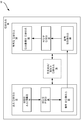
도 2a 는 본 개시에서 설명하는 양태들에 따른 기법들을 구현할 수도 있는 예시적인 비디오 인코더의 예를 예시하는 블록도이다.
도 2b 는 본 개시에서 설명하는 양태들에 따른 기법들을 구현할 수도 있는 예시적인 비디오 디코더의 예를 예시하는 블록도이다.
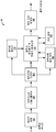
도 3 은 델타 사이즈 유닛-가변 길이 코딩 (Delta size unit-variable length coding; DSU-VLC) 을 이용하여 비디오 데이터의 예시의 코딩의 기능 블록도를 나타낸다.
도 4 는 일부 실시형태들에 따라, 비디오 데이터의 주어진 P x Q 블록의 샘플들을 복수의 샘플 벡터들 (그룹들) 로 파티셔닝하는 일 예를 예시한다.
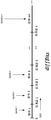
도 5 는 K 개의 임계값들을 이용하여 diffBits 을 K+1 범위들로 세그먼트화하는 것에 의해 QpAdj 를 결정하는 예시적 방법을 예시하는 그래프이다.
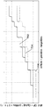
도 6 은 디폴트 방법 및 방법-P1 에 대한 diffBits 의 함수로서 델타 Qp 의 관계를 예시하는 그래프를 나타낸다.
도 7 은 일부 실시형태들에 따라 디폴트 방법, 방법-Q1 및 방법-Q2 에 대한 diffBits 의 함수로서 델타 Qp 의 관계를 예시하는 그래프를 나타낸다.
도 8a 는 저 복잡도 및 고 복잡도 이미지 데이터의 혼합을 갖는 예시적 이미지를 예시한다.
도 8b 및 도 8c 는 도 8a 의 이미지의 상이한 공간 영역들을 코딩하는데 있어 인코더에 의해 이용될 수도 있는 QP 값들을 맵핑하는 예시적 QP 맵들을 예시하며, 여기에서 최대 QP 값은 각각 고정 또는 동적으로 조정된다.
도 9 는 버퍼 충만도 (BF) 의 상이한 범위들에 대한 오프셋 델타 값을 선택하기 위한 예시적 방식의 그래프를 나타낸다.
도 10 은 버퍼 충만도 (BF) 의 상이한 범위들에 대한 오프셋 델타 값을 선택하기 위한 예시적 방식의 그래프를 나타낸다.
도 11 은 비디오 데이터의 블록들을 코딩하기 위한 최대 QP 값을 조정하는 예시적 프로세스의 플로우차트를 나타낸다.1A is a block diagram illustrating an exemplary video encoding and decoding system that may utilize techniques in accordance with aspects described in this disclosure.
1B is a block diagram illustrating another exemplary video encoding and decoding system that may perform techniques in accordance with aspects described in this disclosure.
2A is a block diagram illustrating an example of an exemplary video encoder that may implement techniques in accordance with aspects described in this disclosure.
2B is a block diagram illustrating an example of an exemplary video decoder that may implement techniques in accordance with aspects described in this disclosure.
Figure 3 shows a functional block diagram of coding of an example of video data using Delta size unit-variable length coding (DSU-VLC).
Figure 4 illustrates an example of partitioning samples of a given P x Q block of video data into a plurality of sample vectors (groups), in accordance with some embodiments.
5 is a graph illustrating an exemplary method for determining QpAdj by segmenting diffBits into K + 1 ranges using K thresholds.
6 is a function of diffBits to the default method and method -P 1 shows a graph illustrating the relation delta Qp.
Figure 7 shows a graph illustrating the relationship of delta Qp as a function of diffBits for the default method, method-Q1 and method-Q2, in accordance with some embodiments.
Figure 8A illustrates an exemplary image with a mixture of low complexity and high complexity image data.
8B and 8C illustrate exemplary QP maps that map QP values that may be used by an encoder in coding different spatial regions of the image of FIG. 8A, wherein the maximum QP values are each fixed or dynamically adjusted do.
Figure 9 shows a graph of an exemplary scheme for selecting an offset delta value for different ranges of buffer fullness BF.
Figure 10 shows a graph of an exemplary scheme for selecting an offset delta value for different ranges of buffer fullness BF.
11 shows a flowchart of an exemplary process for adjusting a maximum QP value for coding blocks of video data.
일반적으로, 본 개시는 디스플레이 스트림들을 수반하는데 이용되는 이들 기술들과 같이 비디오 압축 기술을 개선하는 방법들에 관한 것이다. 보다 구체적으로, 본 개시는 QP 조정 값을 계산하는 적절한 기법의 선택을 통하여 양자화 파라미터 (QP) 의 업데이트를 개선하는 시스템들 및 방법들에 관한 것이다.In general, the present disclosure relates to methods for improving video compression techniques, such as those techniques used to accompany display streams. More particularly, this disclosure relates to systems and methods for improving the update of a quantization parameter (QP) through the selection of an appropriate technique for computing a QP adjustment value.
특정 실시형태들이 디스플레이 스트림 압축 (Display Stream Compression; DSC) 표준의 환경에서 본원에 설명되어 있지만, 본원에 개시된 시스템들 및 방법들은 임의의 적절한 비디오 코딩 표준에 적용가능할 수도 있다. 예를 들어, 본원에서 개시된 실시형태들은 다음 표준들 중 하나 이상에 적용가능할 수도 있다: ITU-T (ITU (International Telecommunication Union) Telecommunication Standardization Sector) H.261, ISO/IEC (International Organization for Standardization/International Electrotechnical Commission) MPEG 1 (Moving Picture Experts Group-1) Visual, ITU-T H.262 또는 ISO/IEC MPEG-2 Visual, ITU-T H.263, ISO/IEC MPEG 4 Visual, ITU-T H.264 (또한 ISO/IEC MPEG-4 AVC 로서 알려짐), HEVC (High Efficiency Video Coding), 및 이러한 표준들에 대한 임의의 확장들. 본원에 설명된 기법들은 버퍼 모델을 통합하는 표준들 또는 코딩 기법들에 특히 적용가능할 수도 있다. 여러 실시형태들에서, 일정 비트 레이트 (constant bit rate; CBR) 또는 가변 비트 레이트 (variable bit rate; VBR) 버퍼 모델이 이용될 수도 있다. 또한, 본 개시에 설명된 기법들은 장래에 개발된 표준들의 부분일 수도 있다. 즉, 본 개시에 설명된 기법들은 이전에 개발된 비디오 코딩 표준들, 현재 개발중인 비디오 코딩 표준들, 및 앞으로의 비디오 코딩 표준들에 적용가능할 수도 있다.Although certain embodiments are described herein in the context of the Display Stream Compression (DSC) standard, the systems and methods disclosed herein may be applicable to any suitable video coding standard. For example, the embodiments disclosed herein may be applicable to one or more of the following standards: ITU-T (International Telecommunication Union) Telecommunication Standardization Sector H.261, International Organization for Standardization / International ITU-T H.264 or ISO / IEC MPEG-2 Visual, ITU-T H.263, ISO / IEC MPEG 4 Visual, ITU-T H.264 (Also known as ISO / IEC MPEG-4 AVC), High Efficiency Video Coding (HEVC), and any extensions to these standards. The techniques described herein may be particularly applicable to standards or coding techniques that incorporate a buffer model. In various embodiments, a constant bit rate (CBR) or variable bit rate (VBR) buffer model may be used. In addition, the techniques described in this disclosure may be part of standards developed in the future. That is, the techniques described in this disclosure may be applicable to previously developed video coding standards, video coding standards currently under development, and future video coding standards.
VESA (Video Electronics Standards Association) 에 의해 최근에 마무리된 3:1 디스플레이 스트림 압축 (display stream compression; DSC) v1.0 솔루션의 발생은 본질적으로 4K 와 같은 고해상도 디스플레이들에 대하여 향후 모바일 마켓 요건들을 이끌기에 충분하지 못하다. 따라서, 향후 디맨드들에 대처하기 위해, VESA 는 4:1 이상의 압축 비들을 타겟으로 하는 차세대 DSC 솔루션을 개발하기 위하여 CfT (call for technology) 를 릴리즈하였다.The development of the recently completed 3: 1 display stream compression (DSC) v1.0 solution by the Video Electronics Standards Association (VESA) essentially leads to future mobile market requirements for high-resolution displays such as 4K Not enough. Therefore, in order to cope with future demand, VESA released call for technology (CfT) to develop a next generation DSC solution targeting compression ratios of 4: 1 or higher.
일반적으로, DSC 코더는 낮은 비용, 고정된 레이트의 시각적으로 무손실성인 압축을 제공한다. 코더는 (블록 사이즈 P x Q 를 갖고) 블록 기반 접근방식에 기초하여 설계되고 다수의 코딩 모드들로 구성된다. 예를 들어, 각각의 블록에 대한 이용가능한 코딩 옵션들은 변환 (예를 들어, DCT, 하다마드), 블록 예측, DPCM, 패턴, 미드-포인트 예측 (mid-point prediction; MPP), 및 미드-포인트 예측 폴백 (mid-point predication fall back; MPPF) 모드이다. 수개의 코딩 모드들은 상이한 유형들의 컨텐츠들 또는 이미지들을 효율적으로 압축하기 위하여 코더에 이용된다. 예를 들어, 텍스트 이미지들은 패턴 모드에 의해 효율적으로 압축될 수 있는 한편, 자연 이미지는 변환 모드에 의해 효율적으로 캡처될 수 있다.In general, a DSC coder provides visually lossless compression of a low cost, fixed rate. The coder is designed based on a block-based approach (with block size P x Q) and is composed of multiple coding modes. For example, the available coding options for each block may be a transform (e.g., DCT, Hadamard), block prediction, DPCM, pattern, mid-point prediction And a mid-point predication fall back (MPPF) mode. Several coding modes are used in the coder to efficiently compress different types of content or images. For example, text images can be efficiently compressed by the pattern mode, while natural images can be efficiently captured by the conversion mode.
각각의 블록은 모드의 레이크와 왜곡 양쪽 모두를 고려하는 것에 의해 각각의 블록에 대해 최상의 모드를 선택하려는 목적으로 레이트-제어 메카니즘에 기초하여 복수의 코딩 모드들로부터 하나의 코딩 모드를 선택할 수 있다. 레이트 제어 메카니즘은 버퍼 모델에 의해 지원되고, 이는 버퍼 (예를 들어, 버퍼 유닛) 가 결코 언더플로우 (버퍼에서 제로 비트들보다 더 적음) 또는 오버플로우 (버퍼 사이즈가 설정된 최대 사이즈를 너머서 증가함) 상태에 있지 않는다는 코덱의 설계 요건이다.Each block can select one coding mode from a plurality of coding modes based on a rate-control mechanism for the purpose of selecting the best mode for each block by considering both rake and distortion of the mode. The rate control mechanism is supported by the buffer model, which means that the buffer (e.g., buffer unit) never underflows (less than zero bits in the buffer) or overflows (the buffer size increases beyond the set maximum size ) State of the codec.
비디오 코딩 방법들은 이전에 계산된 QP 값을 QP 조정 값으로 업데이트하는 것에 의해 QP 값을 계산할 수도 있다. QP 조정 값은 이전 블록과 현재 블록 사이의 차이, 예를 들어, 이전 블록을 코딩하는데 요구되는 비트들과, 현재 블록을 코딩하는 비트들의 목표 수 사이의 차이에 기초하여 계산될 수도 있다.The video coding methods may calculate the QP value by updating the previously calculated QP value with the QP adjustment value. The QP adjustment value may be calculated based on the difference between the previous block and the current block, e.g., the difference between the bits required to code the previous block and the target number of bits coding the current block.
그러나, 통상의 기법에 의해 결정된 QP 조정값은 특정한 상황 하에서 현저한 아티팩트들을 야기할 수도 있거나 코딩 비효율성들을 가져올 수도 있다. 예를 들어, QP 조정 값을 결정하기 위한 통상의 기술들은 이미지의 플랫 영역으로부터 복잡한 영역으로 천이하기에 충분히 어그래시브하지 않다 (예를 들어, QP 조정값은 현저한 아티팩트들 없이 보다 양호한 코딩 효율을 가져오는 보다 바람직한 QP 조정값 보다는 더 작을 수도 있다). 플랫 및 복잡한 영역들의 개념들은 아래 보다 자세하게 설명될 것이다.However, the QP adjustment value determined by conventional techniques may cause significant artifacts under certain circumstances or may lead to coding inefficiencies. For example, conventional techniques for determining a QP adjustment value are not sufficiently grayscale to transition from a flat region of an image to a complex region (e.g., the QP adjustment value may provide better coding efficiency without significant artifacts May be less than the more desirable QP adjustment value to import). The concepts of flat and complex regions will be described in more detail below.
추가적으로, 버퍼의 충만도가 비어있거나 또는 충만되어 있는 임계값 내에 있을 때, QP 조정 값을 계산하는 통상의 기술들은 너무 어그래시브할 수도 있어, 디코더에 의해 복원된 이미지에 아티팩트들을 가져온다. 예를 들어, 통상의 기술들에 의해 계산된 QP 조정 값은 QP 조정 값은 복원된 이미지에서 아티팩트가 현저하지 않게 하는 보다 바람직한 QP 조정 값보다 더 클 수도 있다.Additionally, when the fullness of the buffer is within a threshold that is empty or full, the usual techniques for calculating the QP adjustment value may be too graceful, bringing artifacts back into the image restored by the decoder. For example, the QP adjustment value calculated by conventional techniques may be greater than the more preferable QP adjustment value, which makes artifacts less noticeable in the reconstructed image.
따라서 본 개시의 양태들은 위에 나타낸 문제들을 적어도 해결하도록 교시된다. 특정 양태들에서, 이는 위에 나타낸 문제들과 연관될 수도 있는 조건들의 검출 또는 결정을 통하여 그리고 검출된 조건들 하에서 QP 조정 값을 계산하기 위한 하나 이상의 대체 기법들을 적용하는 것을 통하여 실현될 수도 있다.Accordingly, aspects of the disclosure are taught to at least solve the problems set forth above. In certain aspects, this may be accomplished through the detection or determination of conditions that may be associated with the problems presented above and by applying one or more alternative techniques to calculate the QP adjustment value under the detected conditions.
비디오 코딩 표준들Video coding standards
디지털 이미지, 이를 테면, 비디오 레코더, TV 이미지, 정지 화상 또는 비디오 리코더 또는 컴퓨터에 의해 생성된 이미지는 수평 및 수직 라인들에 배열된 픽셀들 또는 샘플들을 포함할 수도 있다. 단일 이미지에서 픽셀들의 수는 일반적으로 수 만 개이다. 각각의 픽셀은 일반적으로 휘도 및 색차 정보를 포함한다. 압축이 없다면, 이미지 인코더로부터 이미지 디코더로 전달되는 정보의 순전한 양은 실시간 이미지 송신을 불가능하게 만들 것이다. 송신되는 정보의 양을 감소시키기 위해, JPEG, MPEG 및 H.263 표준들과 같은, 다수의 상이한 압축 방법들이 개발되었다.A digital image, such as a video recorder, TV image, still image or video recorder, or an image generated by a computer, may contain pixels or samples arranged on horizontal and vertical lines. The number of pixels in a single image is typically tens of thousands. Each pixel typically includes luminance and chrominance information. Without compression, the precise amount of information that is passed from the image encoder to the image decoder will make real-time image transmission impossible. In order to reduce the amount of information to be transmitted, a number of different compression methods have been developed, such as JPEG, MPEG and H.263 standards.
비디오 코딩 표준들은 ITU-T H.261, ISO/IEC MPEG-1 Visual, ITU-T H.262 또는 ISO/IEC MPEG-2 Visual, ITU-T H.263, ISO/IEC MPEG-4 Visual, (또한, ISO/IEC MPEG-4 AVC 로서 알려진) ITU-T H.264, 및 이러한 표준들의 확장을 포함하는 HEVC 를 포함한다.Video coding standards are defined in ITU-T H.261, ISO / IEC MPEG-1 Visual, ITU-T H.262 or ISO / IEC MPEG-2 Visual, ITU-T H.263, ITU-T H.264, also known as ISO / IEC MPEG-4 AVC), and an HEVC including an extension of these standards.
추가로 비디오 코딩 표준, 즉 DSC 는 VESA 에 의해 개발되었다. DSC 표준은 디스플레이 링크들을 통한 송신을 위하여 비디오를 압축할 수 있는 비디오 압축 표준이다. 디스플레이들의 해상도가 증가함에 따라, 디스플레이들을 구동시키는데 요구되는 비디오 데이터의 대역폭도 대응하여 증가한다. 일부 디스플레이 링크들은 이러한 해상도들에 대하여 디스플레이에 비디오 데이터 모두를 송신하기 위한 데역폭을 갖지 않을 수도 있다. 이에 따라, DSC 표준은 디스플레이 링크들을 통한 상호연동가능한 시각적 무손실 압축을 위한 압축 표준을 특정한다.In addition, the video coding standard, DSC, was developed by VESA. The DSC standard is a video compression standard capable of compressing video for transmission over display links. As the resolution of displays increases, the bandwidth of video data required to drive displays also increases correspondingly. Some display links may not have a bandwidth to transmit all of the video data to the display for these resolutions. Accordingly, the DSC standard specifies a compression standard for interlaced visual lossless compression over display links.
DSC 표준은 다른 비디오 코딩 표준들, 이를 테면, H.264 및 HEVC 과는 상이하다. DSC 는 인트라-프레임 압축을 포함하지만, 인터-프레임 압축을 포함하지 않는데, 이는 시간 정보가 비디오 데이터를 코딩함에 있어서 DSC 표준에 의해 이용되지 않을 수도 있음을 의미한다. 이와 대조적으로, 다른 비디오 코딩 표준들은 이들의 비디오 코딩 기법에서 인터-프레임 압축을 채택할 수도 있다.The DSC standard differs from other video coding standards, such as H.264 and HEVC. DSC includes intra-frame compression, but does not include inter-frame compression, which means that the temporal information may not be used by the DSC standard in coding video data. In contrast, other video coding standards may adopt inter-frame compression in their video coding schemes.
비디오 코딩 시스템Video coding system
이하, 신규 시스템들, 장치들 및 방법들의 다양한 양태들이 첨부 도면들을 참조하여 보다 충분히 설명된다. 그러나, 본 개시는 많은 다른 형태들로 구현될 수도 있고, 이 개시 전반에서 제시된 임의의 특정 구조 또는 기능으로 제한되는 것으로 간주되지 않아야 한다. 오히려, 이러한 양태들이 제공되어 본 개시가 철저하고 완벽하게 될 것이고, 당업자들에게 본 개시의 범위을 충분히 전달할 것이다. 본원에서의 교시들에 기초하여, 당업자는 본 개시의 범위가 본 개시의 임의의 다른 양태와 독립적으로 구현되든 그와 결합되든, 본원에서 개시된 신규한 시스템들, 장치들, 및 방법들의 임의의 양태를 포괄하도록 의도되는 것으로 이해하여야 한다. 예를 들어, 본원에 제시된 임의의 수의 양태들을 이용하여 장치가 구현될 수도 있거나 방법이 실시될 수도 있다. 또한, 본 개시의 범위는 본원에서 개시된 본 개시의 여러 양태들에 추가하여 또는 이 이외에, 다른 구조, 기능, 또는 구조 및 기능을 이용하여 실행되는 장치 또는 방법을 포괄하도록 의도된다. 본원에 개시된 개시의 임의의 양태는 청구항의 하나 이상의 요소들에 의해 구체화될 수도 있다.BRIEF DESCRIPTION OF THE DRAWINGS Various aspects of the novel systems, devices and methods are described more fully hereinafter with reference to the accompanying drawings. This disclosure, however, may be embodied in many different forms and should not be construed as limited to any specific structure or function presented in this disclosure. Rather, these aspects are provided so that this disclosure will be thorough and complete, and will fully convey the scope of the disclosure to those skilled in the art. Based on the teachings herein, one of ordinary skill in the art will readily recognize that any scope of the present disclosure, whether implemented independently of any other aspect of the disclosure, And the like. For example, an apparatus may be implemented or a method implemented using any number of aspects set forth herein. Further, the scope of the present disclosure is intended to cover an apparatus or method that is implemented using other structures, functions, or structures and functions in addition to or in addition to the various aspects of the disclosure disclosed herein. Any aspect of the disclosure disclosed herein may be embodied by one or more elements of the claims.
비록 특정 양태들이 본원에서 설명되지만, 이러한 양태들의 많은 변형예들 및 치환예들이 본 개시의 범위 내에 속한다. 비록 바람직한 양태들의 일부 이득들 및 이점들이 언급되었지만, 본 개시의 범위는 특정 이득들, 용도들, 또는 목적들로 제한되고자 하지 않는다. 오히려, 본 개시들의 양태들은 상이한 기술들, 시스템 구성들, 네트워크들, 및 프로토콜들에 널리 적용되고자 하며, 본 개시의 양태들 중 일부는 도면들에서 그리고 다음의 바람직한 양태들의 설명에서 예로서 예시된다. 상세한 설명 및 도면들은 제한하는 것이기 보다는 단지 본 개시의 예시일 뿐이며, 본 개시의 범위는 첨부된 청구항들 및 그의 등가물들에 의해 정의된다.Although specific embodiments are described herein, many variations and permutations of such aspects are within the scope of the present disclosure. Although some benefits and advantages of the preferred embodiments are mentioned, the scope of the present disclosure is not intended to be limited to any particular benefit, use, or purpose. Rather, aspects of the present disclosure are intended to be broadly applicable to different techniques, system configurations, networks, and protocols, and some of the aspects of the disclosure are illustrated by way of example in the drawings and in the description of the following preferred aspects . The description and drawings are by way of example only and not restrictive; the scope of the present disclosure is defined by the appended claims and their equivalents.
첨부의 도면들은 실시형태들을 예시한다. 첨부된 도면들에서 도면 부호들로 나타내어진 엘리먼트들은 다음의 설명에서 유사한 도면 부호들로 나타내어진 요소들에 대응한다. 본 개시에 있어서, 서수적 어구들 (예를 들면, "제 1", "제 2", "제 3" 등) 로 시작하는 명칭들을 갖는 엘리먼트들은 그 엘리먼트들이 반드시 특정한 순서를 갖는 것을 의미하는 것은 아니다. 다만, 이러한 서수적 어구들은, 단지, 동일한 또는 유사한 형태의 상이한 엘리먼트들을 지칭하기 위해 사용된다.The accompanying drawings illustrate embodiments. Elements designated by reference numerals in the accompanying drawings correspond to elements designated by like reference numerals in the following description. In the present disclosure, elements with names beginning with a numerical phrase (e.g., "first", "second", "third", etc.) mean that the elements have a particular order no. However, such descriptive phrases are used merely to refer to different elements of the same or similar type.
도 1a 는 본 개시에서 설명된 양태들에 따른 기법들을 이용할 수도 있는 예시적인 비디오 코딩 시스템 (10) 을 예시하는 블록도이다. 여기에서 이용되어 설명된 바와 같이, 용어 "비디오 코더" 또는 "코더" 는 일반적으로 비디오 인코더들 및 비디오 디코더들 양쪽 모두를 지칭한다. 본 개시에서, 용어들 "비디오 코딩" 또는 "코딩" 은 일반적으로 비디오 인코딩 또는 비디오 디코딩을 지칭할 수도 있다. 비디오 인코더들 및 비디오 디코더들에 더하여, 본원에서 설명된 양태들은 다른 관련 디바이스들, 이를 테면, 트랜스코더들 (예를 들어, 비트스트림을 디코딩하고 다른 비트스트림을 재-인코딩할 수 있는 디바이스들) 및 미들박스들 (middleboxes) (예를 들어, 비트스트림을 수정하고, 변환하고, 및/또는 달리 조작할 수 있는 디바이스들) 로 확장될 수도 있다.1A is a block diagram illustrating an exemplary
도 1a 에 나타낸 바와 같이, 비디오 코딩 시스템 (10) 은 목적지 디바이스 (14) 에 의해 추후 디코딩될 인코딩된 비디오 데이터를 생성하는 소스 디바이스 (12) 를 포함한다. 도 1a 의 예에서, 소스 디바이스 (12) 및 목적지 디바이스 (14) 는 별개의 디바이스들을 구성한다. 그러나, 소스 디바이스 (12) 및 목적지 디바이스 (14) 는 도 1b 의 예에 나타낸 바와 같이 동일한 디바이스 상에 있거나 또는 부분일 수도 있다는 점에 유의한다.As shown in FIG. 1A, the
다시 한번, 도 1a 를 참조하면, 소스 디바이스 (12) 및 목적지 디바이스 (14) 는 데스크톱 컴퓨터들, 노트북 (예를 들어, 랩톱) 컴퓨터들, 태블릿 컴퓨터들, 셋톱 박스들, 전화기 핸드셋들, 이를 테면, 소위 "스마트" 폰들, 소위 "스마트" 패드들, 텔레비전들, 카메라들, 디스플레이 디바이스들, 디지털 미디어 플레이어들, 비디오 게임 콘솔들, 차량내 컴퓨터들, 비디오 스트리밍 디바이스들, 엔티티 (예를 들어, 인간, 동물 및/또는 다른 제어된 디바이스들) 에 의해 (엔티티에) 웨어러블 (또는 제거가능하게 탈착가능한) 디바이스들, 이를 테면, 아이웨어 및/또는 웨어러블 컴퓨터, 엔티티 내에 소비, 섭취 또는 위치되는 디바이스들 또는 장치들 등을 포함한, 광범위한 디바이스들 중 어느 것을 각각 포함할 수도 있다. 여러 실시형태들에서, 소스 디바이스 (12) 및 목적지 디바이스 (14) 는 무선 통신을 위해 설치될 수도 있다.1A, the
목적지 디바이스 (14) 는 디코딩될 인코딩된 비디오 데이터를 링크 (16) 를 통해서 수신할 수도 있다. 링크 (16) 는 인코딩된 비디오 데이터를 소스 디바이스 (12) 로부터 목적지 디바이스 (14) 로 이동시킬 수 있는 임의 종류의 매체 또는 디바이스를 포함할 수도 있다. 도 1a 의 예에서, 링크 (16) 는 소스 디바이스 (12) 로 하여금 인코딩된 비디오 데이터를 목적지 디바이스 (14) 로 실시간으로 송신할 수 있게 하는 통신 매체를 포함할 수도 있다. 인코딩된 비디오 데이터는 무선 통신 프로토콜과 같은 통신 표준에 따라서 변조되어 목적지 디바이스 (14) 로 송신될 수도 있다. 통신 매체는 임의의 무선 또는 유선 통신 매체, 이를 테면 무선 주파수 (RF) 스펙트럼 또는 하나 이상의 물리적 송신 라인들을 포함할 수도 있다. 통신 매체는 패킷 기반의 네트워크, 예컨대 근거리 통신망(local area network), 원거리 통신망(wide-area network), 또는 인터넷과 같은 글로벌 네트워크의 일부를 형성할 수도 있다. 통신 매체는 라우터들, 스위치들, 기지국들, 또는 소스 디바이스 (12) 로부터 목적지 디바이스 (14) 로 통신을 용이하게 하는데 유용할 수도 있는 임의의 다른 장비를 포함할 수도 있다.The destination device 14 may receive the encoded video data to be decoded via the
도 1a 의 예에서, 소스 디바이스 (12) 는 비디오 소스 (18), 비디오 인코더 (20), 및 출력 인터페이스 (22) 를 포함한다. 일부의 경우, 출력 인터페이스 (22) 는 변조기/복조기 (모뎀) 및/또는 송신기를 포함할 수도 있다. 소스 디바이스 (12) 에서, 비디오 소스 (18) 는 비디오 캡처 디바이스, 예를 들어 비디오 카메라와 같은 소스, 이전에 캡처된 비디오를 포함하는 비디오 아카이브, 비디오 컨텐츠 공급자로부터 비디오를 수신하는 비디오 피드 인터페이스, 및/또는 소스 비디오로서 컴퓨터 그래픽 데이터를 생성하는 컴퓨터 그래픽 시스템, 또는 이러한 소스들의 조합을 포함할 수도 있다. 일 예로서, 비디오 소스 (18) 가 비디오 카메라이면, 소스 디바이스 (12) 및 목적지 디바이스 (14) 는 도 1b 의 예에 예시된 바와 같이, 소위 "카메라 폰들" 또는 "비디오 폰들"을 형성할 수도 있다. 그러나, 본 개시에서 설명된 기술들은 일반적으로 비디오 코딩에 적용가능할 수도 있으며, 무선 및/또는 유선 애플리케이션들에 적용될 수도 있다.In the example of FIG. 1A, the
캡처된, 프리캡처된, 또는 컴퓨터에 의해 생성된 비디오는 비디오 인코더 (20) 에 의해 인코딩될 수도 있다. 인코딩된 비디오 데이터는 소스 디바이스 (12) 의 출력 인터페이스 (22) 를 통해서 목적지 디바이스 (14) 에 직접 송신될 수도 있다. 인코딩된 비디오 데이터는 또한 (또는, 대안적으로) 디코딩 및/또는 플레이백을 위해, 목적지 디바이스 (14) 또는 다른 디바이스들에 의한 추후 액세스를 위해, 저장 디바이스 (31) 상에 저장될 수도 있다. 도 1a 및 도 1b 에 예시된 비디오 인코더 (20) 는 도 2a 에 예시된 비디오 인코더 (20) 또는 본원에서 설명되는 임의의 다른 비디오 인코더를 포함할 수도 있다.The captured, prepcaptured, or computer generated video may be encoded by the
도 1a 의 예에서, 목적지 디바이스 (14) 는 입력 인터페이스 (28), 비디오 디코더 (30), 및 디스플레이 디바이스 (32) 를 포함한다. 일부 경우, 입력 인터페이스 (28) 는 수신기 및/또는 모뎀을 포함할 수도 있다. 목적지 디바이스 (14) 의 입력 인터페이스 (28) 는 링크 (16) 를 통해서 및/또는 저장 디바이스 (31) 로부터 인코딩된 비디오 데이터를 수신할 수도 있다. 링크 (16) 를 통해서 통신되거나, 또는 저장 디바이스 (31) 상에 제공되는 인코딩된 비디오 데이터는, 비디오 데이터를 디코딩할 때에, 비디오 디코더 (30) 와 같은 비디오 디코더에 의해 이용하기 위한, 비디오 인코더 (20) 에 의해 생성되는 다양한 신택스 엘리먼트들을 포함할 수도 있다. 이러한 신택스 엘리먼트들은 통신 매체 상에서 송신되거나, 저장 매체 상에 저장되거나, 또는 파일 서버 상에 저장된 인코딩된 비디오 데이터와 함께 포함될 수도 있다. 도 1a 및 도 1b 에 예시된 비디오 디코더 (30) 는 도 2b 에 예시된 비디오 디코더 (30) 또는 본원에서 설명되는 임의의 다른 비디오 디코더를 포함할 수도 있다.In the example of FIG. 1A, the destination device 14 includes an
디스플레이 디바이스 (32) 는 목적지 디바이스 (14) 와 통합될 수도 있거나 또는 목적지 디바이스 (14) 외부에 있을 수도 있다. 일부 예들에서, 목적지 디바이스 (14) 는 통합 디스플레이 디바이스를 포함할 수도 있고 외부 디스플레이 디바이스와 인터페이스하도록 또한 구성될 수도 있다. 다른 예들에서, 목적지 디바이스 (14) 는 디스플레이 디바이스일 수도 있다. 일반적으로, 디스플레이 디바이스 (32) 는 디코딩된 비디오 데이터를 사용자에게 디스플레이하고, 액정 디스플레이 (LCD), 플라즈마 디스플레이, 유기 발광 다이오드 (OLED) 디스플레이, 또는 다른 유형의 디스플레이 디바이스와 같은 다양한 디스플레이 디바이스들 중 어는 것을 포함할 수도 있다.The
관련된 양태들에서, 도 1b 는 예시적인 비디오 인코딩 및 디코딩 시스템 (10') 을 나타내며, 여기서 소스 디바이스 (12) 및 목적지 디바이스 (14) 는 디바이스 (11) 상에 있거나 또는 그 부분이다. 디바이스 (11) 는 "스마트" 폰 등과 같은, 전화기 핸드셋일 수도 있다. 디바이스 (11) 는 소스 디바이스 (12) 및 목적지 디바이스 (14) 와 동작적으로 통신하는 프로세서/제어기 디바이스 (13)(선택적으로 존재함) 를 포함할 수도 있다. 도 1b 의 비디오 코딩 시스템 (10') 및 이들의 컴포넌트들은 그 외에, 도 1a 의 비디오 코딩 시스템 (10) 및 이들의 컴포넌트들과 유사하다.1B illustrates an exemplary video encoding and decoding system 10 'in which
비디오 인코더 (20) 및 비디오 디코더 (30) 는 비디오 압축 표준, 이를 테면, DSC 에 따라 동작할 수도 있다. 이의 대안으로, 비디오 인코더 (20) 및 비디오 디코더 (30) 는 MPEG 4, Part 10, AVC, HEVC 또는 이러한 표준의 확장으로서 대안적으로 지칭되는 다른 독점적 또는 산업 표준들에 따라 동작할 수도 있다. 그러나, 본 개시의 기술들은 임의의 특정 코딩 표준에 제한되지 않는다. 비디오 압축 표준들의 다른 예들은 MPEG-2 및 ITU-T H.263 을 포함한다.
도 1a 및 도 1b 의 예에 나타내지는 않지만, 비디오 인코더 (20) 및 비디오 디코더 (30) 는 오디오 인코더 및 디코더와 각각 통합될 수도 있으며, 오디오 및 비디오 양쪽의 인코딩을 공통 데이터 스트림 또는 별개의 데이터 스트림들에서 처리하기에 적합한 MUX-DEMUX 유닛들, 또는 다른 하드웨어 및 소프트웨어를 포함할 수도 있다. 적용 가능하다면, 일부 예들에서, MUX-DEMUX 유닛들은 ITU H.223 멀티플렉서 프로토콜, 또는 유저 데이터그램 프로토콜 (UDP) 과 같은 다른 프로토콜을 따를 수도 있다.Although not shown in the example of FIGS. 1A and 1B,
비디오 인코더 (20) 및 비디오 디코더 (30) 각각은 하나 이상의 마이크로프로세서들, 디지털 신호 프로세서들 (DSP들), 주문형 집적회로들 (ASIC들), 필드 프로그래밍가능 게이트 어레이들 (FPGA들), 이산 로직, 소프트웨어, 하드웨어, 펌웨어 또는 임의의 이들의 조합들과 같은, 다양한 적합한 인코더 회로 중 임의의 회로로 구현될 수도 있다. 상기 기술이 부분적으로 소프트웨어로 구현되는 경우, 디바이스는 그 소프트웨어에 대한 명령들을 적절한 비일시적 컴퓨터 판독가능 매체에 저장할 수도 있고, 본 개시의 기술들을 수행하기 위해 하나 이상의 프로세서들을 사용하는 하드웨어에서 그 명령들을 실행할 수도 있다. 비디오 인코더 (20) 및 비디오 디코더 (30) 각각은 하나 이상의 인코더들 또는 디코더들에 포함될 수도 있으며, 이들 중 어느 한쪽은 각각 디바이스에서 결합된 인코더/디코더의 부분으로서 통합될 수도 있다.
비디오 코딩 프로세스Video coding process
위에서 간단히 언급한 바와 같이, 비디오 인코더 (20) 는 비디오 데이터를 인코딩한다. 비디오 데이터는 픽쳐들의 하나 이상의 픽처들을 포함할 수도 있다. 픽처들 각각은 비디오의 일부를 형성하는 정지 화상이다. 일부 사례들에서, 픽처는 비디오 "프레임"으로 지칭될 수도 있다. 비디오 인코더 (20) 가 비디오 데이터를 인코딩할 때, 비디오 인코더 (20) 는 비트스트림을 생성할 수도 있다. 비트스트림은 비디오 데이터의 코딩된 표현을 형성하는 비트들의 시퀀스를 포함할 수도 있다. 비트스트림은 코딩된 픽처들 및 연관된 데이터를 포함할 수도 있다. 코딩된 픽처는 픽처의 코딩된 표현이다.As briefly mentioned above,
비트스트림을 생성하기 위해, 비디오 인코더 (20) 는 비디오 데이터에서 각각의 픽처에 관해 인코딩 동작들을 수행할 수도 있다. 비디오 인코더 (20) 가 픽처들에 관해 인코딩 동작들을 수행할 때, 비디오 인코더 (20) 는 일련의 코딩된 픽처들 및 연관되는 데이터를 생성할 수도 있다. 연관된 데이터는 코딩 파라미터들의 세트, 이를 테면, QP 를 포함할 수도 있다. 코딩된 픽처를 생성하기 위해, 비디오 인코더 (20) 는 픽처를 동일-사이즈의 비디오 블록들로 파티셔닝할 수도 있다. 비디오 블록은 샘플들의 2 차원 어레이일 수도 있다. 코딩 파라미터들은 코딩 옵션 (예를 들어, 코딩 모드) 를 비디오 데이터의 매 블록마다 정의할 수도 있다. 코딩 옵션은 원하는 레이트 왜곡 성능을 실현하기 위하여 선택될 수도 있다.To generate the bitstream, the
일부 예들에서, 비디오 인코더 (20) 는 픽처를 복수의 슬라이스들로 파티셔닝할 수도 있다. 슬라이스들 각각은 이미지 (예를 들어, 프레임) 에서의 공간적으로 별개인 영역을 포함할 수도 있고, 이 영역은 이미지 또는 프레임에서 나머지 영역들로부터의 정보 없이 독립적으로 디코딩될 수 있다. 각각의 이미지 또는 비디오 프레임이 단일의 슬라이스에서 인코딩될 수도 있거나 각각의 이미지 또는 비디오가 수개의 슬라이스들에서 인코딩될 수도 있다. DSC 에서, 각각의 슬라이스를 인코딩하도록 할당된 타겟 비트들은 실질적으로 일정할 수도 있다. 픽처에 대해 인코딩 동작을 수행하는 부분으로서, 비디오 인코더 (20) 는 그 픽처의 각각의 슬라이스에 대해 인코딩 동작들을 수행할 수도 있다. 비디오 인코더 (20) 가 슬라이스에 대해 인코딩 동작을 수행할 때, 비디오 인코더 (20) 는 그 슬라이스와 연관되는 인코딩된 데이터를 생성할 수도 있다. 슬라이스와 연관된 인코딩된 데이터는 "코딩된 슬라이스" 로서 지칭될 수도 있다.In some instances, the
DSC 비디오 인코더DSC video encoder
도 2a 는 본 개시에서 설명하는 양태들에 따른 기법들을 구현할 수도 있는 예시적인 비디오 인코더 (20) 의 예를 예시하는 블록도이다. 비디오 인코더 (20) 는 본 개시의 기법들 중 일부 또는 모두를 수행하도록 구성될 수도 있다. 일부 예들에서, 본 개시에 설명된 기법들은 비디오 인코더 (20) 의 여러 컴포넌트들 사이에 공유될 수도 있다. 일부 예들에서, 추가적으로 또는 대안적으로, 프로세서 (미도시) 는 본 개시에 설명되는 기법들 중 임의의 기법 또는 모두를 수행하도록 구성될 수도 있다.2A is a block diagram illustrating an example of an
설명의 목적을 위해, 본 개시는 DSC 코딩의 맥락에서 비디오 인코더 (20) 를 기술한다. 그러나, 본 개시의 기술들은 다른 코딩 표준들 또는 방법들에 적용될 수도 있다.For purposes of explanation, the present disclosure describes a
도 2a 의 예에서, 비디오 인코더 (20) 는 복수의 기능적 컴포넌트들을 포함한다. 비디오 인코더 (20) 의 기능적 컴포넌트들은 컬러-공간 컨버터 (105), 버퍼 (110), 플랫화도 검출기 (115), 레이트 제어기 (120), 예측기, 양자화기 및 복원기 컴포넌트 (125), 라인 버퍼 (130), 인덱싱된 컬러 이력 (135), 엔트로피 인코더 (140), 서브스트림 멀티플렉서 (145) 및 레이트 버퍼 (150) 를 포함한다. 다른 예들에서, 비디오 인코더 (20) 는 더 많거나, 더 적거나, 또는 상이한 기능적 컴포넌트들을 포함할 수도 있다.In the example of FIG. 2A,
컬러-공간 컨버터 (105) 는 입력 컬러-공간을 코딩 구현에 이용된 컬러 공간으로 변환할 수도 있다. 예를 들어, 일 예시적 실시형태에서, 입력 비디오 데이터의 컬러-공간은 적색, 녹색 및 청색 (RGB) 에 있으며, 코딩은 루미넌스 (Y), 크로미넌스 그린 (Cg), 및 크로미넌스 오렌지 (Co)(YCgCo) 컬러-공간에서 구현된다. 컬러 공간 변환은 비디오 데이터에 대한 시프트들 및 추가를 포함하는 방법(들)에 의해 수행될 수도 있다. 다른 컬러-공간들에서의 입력 비디오 데이터가 프로세싱될 수도 있고 다른 컬러-공간들에 대한 변환들이 또한 수행될 수도 있음을 주지해야 한다.The color-
관련 양태들에서, 비디오 인코더 (20) 는 버퍼 (110), 라인 버퍼 (130) 및/또는 레이트 버퍼 (150) 를 포함할 수도 있다. 예를 들어, 버퍼 (110) 는 비디오 인코더 (20) 의 다른 부분들에 의한 버퍼 (110) 의 이용 전에 컬러 공간 변환된 비디오 데이터를 홀딩할 수도 있다. 다른 예에서, 비디오 데이터는 RGB 컬러-공간에 저장될 수도 있고, 컬러-공간 변환된 데이터가 더 많은 비트들을 필요로 할 수도 있기 때문에 컬러-공간 변환이 필요에 따라 수행될 수도 있다.In related aspects, the
레이트 버퍼 (150) 는 레이트 제어기 (120) 와 연계하여 아래 보다 자세하게 설명된 비디오 인코더 (20) 에서의 레이트 제어 메카니즘의 부분으로서 기능할 수도 있다. 각각의 블록을 인코딩할 때 소요되는 비트들은 블록의 특성에 매우 실질적으로 기초하여 변동할 수 있다. 레이트 버퍼 (150) 는 압축된 비디오에서 레이트 변동들을 평활하게 할 수 있다. 일부 실시형태들에서, CBR 버퍼 모델 또는 동작 모드가 채택되어, 비트들이 일정한 비트 레이트에서 버퍼로부터 취출된다. 다른 실시형태들에서, VBR 버퍼 모델 또는 동작 모드가 채택될 수도 있어, 비트들이 가변 레이트 (일정하지 않은 비트 레이트) 에서 버퍼로부터 취출된다. 일부 실시형태들에서, 비디오 인코더 (20) 가 너무 많은 비트들을 비트스트림에 추가하면 (예를 들어, 레이트 비트들 보다 더 높은 레이트에서 버퍼로부터 취출되면), 레이트 버퍼 (150) 가 오버플로우할 수도 있다. 한편, 비디오 인코더 (20) 는 또한, 레이트 버퍼 (150) 의 언더플로우를 방지하기 위하여 충분한 비트들을 추가할 필요가 있을 수도 있다.The rate buffer 150 may serve as part of the rate control mechanism in the
비디오 디코더 측에서, 비트들은 일정한 비트 레이트에서 비디오 디코더 (30) 의 레이트 버퍼 (155) 에 추가될 수도 있고 (아래 보다 자세하게 설명될 도 2b 를 참조함), 비디오 디코더 (30) 는 각각의 블록마다 가변 수의 비트들을 제거할 수도 있다. 적절한 디코딩을 보장하기 위하여, 비디오 디코더 (30) 의 레이트 버퍼 (155) 는 압축된 비트스트림의 디코딩 동안 "언더플로우" 또는 "오버플로우"하지 않아야 한다.On the video decoder side, the bits may be added to the
일부 실시형태들에서, 버퍼 충만도 (BF) 는 버퍼에서 현재 비트들의 수를 표현하는 BufferCurrentSize 와 레이트 버퍼 (150) 의 사이즈, 즉, 임의의 시점에서 레이트 버퍼 (150) 에 저장될 수 있는 비트들의 최대 수를 표현하는 BufferMaxSize 의 값들에 기초하여 정의될 수 있다. BF 는 다음과 같이 계산될 수도 있다:In some embodiments, the buffer fullness BF is a function of the BufferCurrentSize representing the number of current bits in the buffer and the size of the rate buffer 150, i. E., The number of bits that can be stored in the rate buffer 150 at any time Can be defined based on the values of BufferMaxSize representing the maximum number. BF may be calculated as follows:
BF = ((BufferCurrentSize * 100) / BufferMaxSize)BF = ((BufferCurrentSize * 100) / BufferMaxSize)
BF 를 계산하는 위의 접근방식은 단지 일 예시에 불과하며, BF 는 특정 구현 또는 문맥에 따라 임의의 수의 상이한 방식들로 계산될 수도 있음을 주지한다.It should be noted that the above approach of calculating BF is merely exemplary and that BF may be computed in any number of different ways depending on the particular implementation or context.
플랫화도 검출기 (115) 는 비디오 데이터에서의 복잡한 (즉, 비-플랫) 영역으로부터 비디오 데이터에서의 플랫 (즉, 단순 또는 균일한) 영역으로의 변화들 또는 플랫 영역으로부터 복잡한 영역으로의 변화들을 검출할 수 있다. 용어 "복잡" 및 "플랫" 은 본원에서, 비디오 인코더 (20) 가 비디오 데이터의 개별적인 영역들을 인코딩하는 데 있어 난이도를 일반적으로 지칭하는데 이용될 것이다. 따라서, 본원에 이용된 용어, 복잡은 일반적으로, 비디오 인코더 (20) 가 인코딩하는데 복잡한 것으로서 비디오 데이터의 영역을 기술하고 예를 들어, 텍스처링된 비디오 데이터, 높은 공간 주파수 및/또는 인코딩하게 복잡한 다른 피처들을 포함할 수도 있다. 본원에 이용된 용어, 플랫은 일반적으로, 비디오 인코더 (20) 가 인코딩하는데 단순한 것으로서 비디오 데이터의 영역을 기술하고 예를 들어, 비디오 데이터에서의 평활한 기울기, 낮은 공간 주파수 및/또는 인코딩하게 단순한 다른 피처들을 포함할 수도 있다. 복잡한 영역으로부터 플랫 영역으로의 천이들은 비디오 인코더 (20) 에 의해, 인코딩된 비디오 데이터에서의 양자화 아티팩트들을 감소시키는데 이용될 수도 있다. 구체적으로 레이트 제어기 (120) 및 예측기, 양자화기 및 복원기 컴포넌트 (125) 는 복잡한 영역으로부터 플랫 영역으로의 천이들이 식별될 때 이러한 양자화 아티팩트들을 감소시킬 수 있다. 이와 유사하게, 플랫 영역으로부터 복잡한 영역으로의 천이들은 비디오 인코더 (20) 에 의해, 현재 블록을 코딩하는데 요구되는 예상 레이트를 감소시키기 위하여 QP 를 증가시키는데 이용될 수도 있다.The
레이트 제어기 (120) 는 코딩 파라미터들의 세트, 예를 들어, QP 를 결정한다. QP 는 레이트 버퍼 (150) 가 오버플로우 또는 언더플로우하지 않음을 보장하는 타겟 비트레이트에 대한 픽처 품질을 최대로 하기 위해, 레이트 버퍼 (150) 의 버퍼 충만도 및 비디오 데이터의 이미지 액티비티 (예를 들어, 복잡한 영역으로부터 플랫 영역으로의 천이 또는 그 반대의 천이) 에 기초하여 레이트 제어기 (120) 에 의해 조정될 수도 있다. 레이트 제어기 (120) 는 또한 최적의 레이트-왜곡 성능을 실현하기 위하여 비디오 데이터의 각각의 블록마다 특정 코딩 옵션 (예를 들어, 특정 모드) 를 선택한다. 레이트 제어기 (120) 는 왜곡이 비트-레이트 제약을 만족하도록, 즉 전체적인 실제 코딩 레이트가 타겟 비트 레이트 내에 맞추어지도록 복원된 이미지들의 왜곡을 최소화한다. 따라서, 레이트 제어기 (120) 의 일 목적은 레이트 왜곡 성능을 최대로 하면서 레이트에 대한 순시적 평균 제약을 만족하도록 코딩 파라미터들의 세트, 이를 테면, QP(들), 코딩 모드(들) 등의 세트를 결정하는 것이다.
예측기, 양자화기 및 복원기 컴포넌트 (125) 는 비디오 인코더 (20) 의 적어도 3 개의 인코딩 동작들을 수행할 수도 있다. 예측기, 양자화기 및 복원기 컴포넌트 (125) 는 복수의 상이한 모드들에서 예측을 수행할 수도 있다. 하나의 일 예의 예측 모드는 메디안 적응적 예측 (median-adaptive prediction) 의 수정된 버전이다. 메디안 적응적 예측은 무손실성 JPEG 표준 (lossless JPEG standard; JPEG-LS) 에 의해 구현될 수도 있다. 예측기, 양자화기 및 복원기 컴포넌트 (125) 에 의해 수행될 수도 있는 메디안-적응적 예측의 수정된 버전은 3 개의 연속하는 샘플 값들의 병렬 예측을 고려할 수도 있다. 다른 예의 예측 모드는 블록 예측이다. 블록 예측에서, 위의 라인에서 이전에 복원된 픽셀들로부터 또는 동일한 라인에서 좌측으로 샘플들이 예측된다. 일부 실시형태들에서, 비디오 인코더 (20) 및 비디오 디코더 (30) 는 양쪽이 복원된 픽셀들에 대한 동일한 검색을 수행하여 블록 예측 이용을 결정할 수도 있고, 이에 따라 블록 예측 모드에서 비트들이 전송될 필요가 없다. 다른 실시형태들에서, 비디오 인코더 (20) 는 검색을 수행하고 비트스트림에서 블록 예측 벡터들을 시그널링할 수도 있어, 비디오 디코더 (30) 가 별도의 검색을 수행할 필요가 없다. 중점 예측 모드가 또한 구현될 수도 있고, 여기에서 샘플들이 컴포넌트 범위의 중점을 이용하여 예측된다. 중점 예측 모드는 최악의 경우의 샘플에서도 압축된 비디오에 대하여 요구되는 수의 비트들의 번들링을 가능하게 할 수도 있다.The predictor, quantizer and restorer component 125 may perform at least three encoding operations of the
예측기, 양자화기 및 복원기 컴포넌트 (125) 는 또한 양자화를 수행한다. 예를 들어, 양자화는 시프터를 이용하여 구현될 수 있는 2 의 누승의 양자화기를 통하여 수행될 수도 있다. 다른 양자화 기법들이 2 의 누승 양자화기 대신에 구현될 수도 있다. 예측기, 양자화기 및 복원기 컴포넌트 (125) 에 의해 수행된 양자화는 레이트 제어기 (120) 에 의해 결정된 QP 에 기초할 수도 있다. 마지막으로, 예측기, 양자화기 및 복원기 컴포넌트 (125) 는 또한, 역 양자화 잔차를 예측된 값에 가산하고 결과가 샘플 값들의 유효 범위의 밖에 들지 않는 것을 보장하는 것을 포함하는 복원을 수행한다.The predictor, quantizer and restorer component 125 also performs quantization. For example, the quantization may be performed through a power of two, which may be implemented using a shifter. Other quantization techniques may be implemented instead of a scalar quantizer of 2. The quantization performed by the predictor, quantizer and restorer component 125 may be based on the QP determined by the
예측기, 양자화기 및 복원기 컴포넌트 (125) 에 의해 수행된 예측, 양자화 및 복원에 대한 위의 설명된 예의 접근방식들은 단지 일 예에 불과하며 다른 접근 방식들이 구현될 수도 있음을 주지한다. 또한, 예측기, 양자화기 및 복원기 컴포넌트 (125) 는 예측, 양자화 및/또는 복원을 수행하는 서브컴포넌트(들)을 포함할 수도 있음을 주지한다. 추가로, 예측, 양자화 및/또는 복원은 예측기, 양자화기 및 복원기 컴포넌트 (125) 대신에 수개의 별개의 인코더 컴포넌트들에 의해 수행될 수도 있음을 주지한다.It should be noted that the above described example approaches to prediction, quantization and reconstruction performed by the predictor, quantizer and restorer component 125 are merely exemplary and other approaches may be implemented. It is also noted that the predictor, quantizer, and restorer component 125 may include subcomponent (s) for performing prediction, quantization, and / or reconstruction. It is further noted that prediction, quantization, and / or reconstruction may be performed by several separate encoder components instead of predictor, quantizer, and reconstructor component 125. [
라인 버퍼 (130) 는 예측기, 양자화기 및 복원기 컴포넌트 (125) 로부터의 출력을 홀딩하여, 예측기, 양자화기 및 복원기 컴포넌트 (125) 및 인덱싱된 컬러 이력 (135) 이 버퍼링된 비디오 데이터를 이용할 수 있게 된다. 인덱싱된 컬러 이력 (135) 은 최근에 이용된 픽셀 값들을 저장한다. 이들 최근에 이용된 픽셀 값들은 전용 신택스를 통하여 비디오 인코더 (20) 에 의해 직접 참조될 수 있다.The
엔트로피 인코더 (140) 는 인덱싱된 컬러 이력 (135) 및 플랫화도 검출기 (115) 에 의해 식별된 플랫화도 천이들에 기초하여 예측기, 양자화기 및 복원기 컴포넌트 (125) 로부터 수신된 에측 잔차들 및 임의의 다른 데이터 (예를 들어, 예측기, 양자화기 및 복원기 컴포넌트 (125) 에 의해 식별된 인덱스들) 를 인코딩한다. 일부 예들에서, 엔트로피 인코더 (140) 는 서브스트림 인코더 마다의 클록 당 3 개의 샘플들을 인코딩할 수도 있다. 서브스트림 멀티플렉서 (145) 는 무헤더 패킷 멀티플렉싱 방식에 기초하여 비트스트림을 멀티플렉싱할 수도 있다. 이는 비디오 디코더 (30) 가 3 개의 엔트로피 디코더들을 병렬로 구동하게 허용하여 클록 당 3 개의 픽셀들의 디코딩을 용이하게 한다. 서브스트림 멀티플렉서 (145) 는 패킷들이 비디오 디코더 (30) 에 의해 효율적으로 디코딩될 수 있도록 패킷순서를 최적화할 수 있다. 엔트로피 코딩에 대한 상이한 접근 방식들이 구현될 수도 있고 이는 클록 당 2 의 누승 픽셀들 (예를 들어, 2 픽셀들/클록 또는 4 픽셀들/클록) 의 디코딩을 용이하게 할 수도 있음을 주지한다.The
DSC 비디오 디코더DSC video decoder
도 2b 는 본 개시에서 설명하는 양태들에 따른 기법들을 구현할 수도 있는 예시적인 비디오 디코더 (30) 의 예를 예시하는 블록도이다. 비디오 디코더 (30) 는 본 개시의 기법들 중 일부 또는 모두를 수행하도록 구성될 수도 있다. 일부 예들에서, 본 개시에서 설명하는 기법들은 비디오 디코더 (30) 의 여러 컴포넌트들 사이에 공유될 수도 있다. 일부 예들에서, 추가적으로 또는 대안적으로, 프로세서 (미도시) 는 본 개시에 설명되는 기법들 중 임의의 기법 또는 모두를 수행하도록 구성될 수도 있다.2B is a block diagram illustrating an example of an
설명의 목적을 위해, 본 개시는 DSC 코딩의 맥락에서의 비디오 디코더 (30) 를 기술한다. 그러나, 본 개시의 기술들은 다른 코딩 표준들 또는 방법들에 적용될 수도 있다.For purposes of explanation, the present disclosure describes a
도 2b 의 예에서, 비디오 디코더 (30) 는 복수의 기능적 컴포넌트들을 포함한다. 비디오 디코더 (30) 의 기능적 컴포넌트들은 레이트 버퍼 (155), 서브스트림 디멀티플렉서 (160), 엔트로피 디코더 (165), 레이트 제어기 (170), 예측기, 양자화기 및 복원기 컴포넌트 (175), 인덱싱된 컬러 이력 (180), 라인 버퍼 (185), 및 컬러-공간 컨버터 (190) 를 포함한다. 비디오 디코더 (30) 의 예시된 컴포넌트들은 도 2a 에서의 비디오 인코더 (20) 와 연계하여 위에 설명된 대응 컴포넌트들과 유사하다. 이로써, 비디오 디코더 (30) 의 컴포넌트들 각각은 위에 설명된 비디오 인코더 (20) 의 대응 컴포넌트들과 유사한 방식으로 동작할 수도 있다.In the example of FIG. 2B,
양자화 파라미터 (QP)The quantization parameter (QP)
위에 논의된 바와 같이, 인코더 (20) 의 예측기, 양자화기 및 복원기 컴포넌트 (125) 는 비디오 데이터의 블록에서 왜곡을 도입할 수도 있는 양자화를 수행할 수도 있다. 왜곡의 양은 블록의 양자화 파라미터 (QP) 에 의해 제어될 수 있다. 예를 들어, 인코더 (20) 는 블록의 비디오 데이터의 컬러 컴포넌트 값들을 양자화하는 양자화 스텝 사이즈를 결정하기 위해 블록에 대한 QP 를 이용할 수도 있다. 일부 실시형태들에서, 인코더 (20) 가 각각의 QP 에 대한 양자화 스텝 사이즈를 저장하는 것에 대신하여, 인코더 (20) 는 QP 의 함수로서 스케일링 매트릭스를 특정할 수도 있다. 각각의 QP 에 대한 양자화 스텝 사이즈는 스케일링 매트릭스로부터 유도될 수 있고, 여기에서 유도된 값은 반드시 2 의 누승일 필요가 있는 것은 아니며, 예를 들어, 유도된 값은 또한 2 의 누승이 아닐 수 있다.As discussed above, the predictor, quantizer and restorer component 125 of
DSC 테스트 모델의 일부 실시형태들에서, 루미넌스 채널에 대한 개별적인 최소 및 최대 QP 는 8bpc 에 대해 16 및 56 으로 설정된다. 각각의 루미넌스 QP 에 대해, 온 더 플라이 (on the fly) 방식으로 유도될 수 있거나 룩업 테이블로부터 추론될 수 있는 연관 크로미넌스 QP 가 있을 수도 있다.In some embodiments of the DSC test model, the individual minimum and maximum QP for the luminance channel is set to 16 and 56 for 8 bpc. For each luminance QP, there may be an associated chrominance QP that can be derived on-the-fly or deduced from the look-up table.
스킵 모드Skip Mode
비디오 데이터의 주어진 블록에서의 단일 컴포넌트의 모든 값들이 제로이면 인코더 (20) 는 스킵 모드를 이용하여 블록을 효율적으로 코딩할 수도 있다. 스킵 모드 코딩의 일부 실시형태들에서, 인코더 (20) 는 디코더 (30) 에 의해 판독될 수도 있는 1-비트 플래그를 시그널링할 수도 있어, 현재 블록이 (모든 값들이 제로이면) 스킵 모드를 이용하여 코딩되는지 또는 (블록에서의 적어도 하나의 값이 비제로이면) 스킵 모드에 있지 않은지를 표시한다.If all values of a single component in a given block of video data are zero then the
델타 사이즈 유닛-가변 길이 코딩Delta size unit - variable length coding
도 3 은 델타 사이즈 유닛-가변 길이 코딩 (DSU-VLC) 을 이용한 비디오 데이터의 코딩의 일 예를 나타낸다. 일부 실시형태들에서, 인코더 (20) 는 DSU-VLC 프로세서 (304) 를 이용하여 K-길이 샘플 벡터 (302)(또한 "그룹"으로서 지칭됨) 의 양자화된 잔차 값들을 비트들의 코딩된 시퀀스 (306) 로 코딩할 수도 있다. 비트들의 코딩된 시퀀스 (306) 는 프리픽스 (308) 및 서픽스 (310) 를 포함할 수도 있고, 여기에서 서픽스 (310) 는 복수의 서픽스 부분들을 포함한다. DSU-VLC 프로세서 (304) 는 도 2a 에 예시된 엔트로피 인코더 (140) 에 대응할 수도 있다. 본원에 이용된 샘플들은 단일의 컬러 컴포넌트에서의 값을 지칭할 수도 있고, 예를 들어, RGB 444 에 대해 각각의 픽셀은 3 개의 샘플들을 갖는다.Figure 3 shows an example of coding of video data using delta size unit-variable length coding (DSU-VLC). In some embodiments, the
프리픽스 (308) 는 서픽스 (310) 의 서픽스 부분들 각각의 잔차 값의 사이즈 (예를 들어, 비트들의 길이)(사이즈는 B 비트들로 표기됨) 를 표시한다. 일부 실시형태들에서 프리픽스 (308) 는 1진수 코드를 이용하여 코딩되고 가변 길이로 이루어질 수도 있다. 서픽스 (310) 는 샘플 벡터 (302) 에서의 모든 샘플들의 실제 잔차 값들을 표시한다 (예를 들어, 서픽스 (310) 의 각각의 서픽스 부분은 샘플 벡터 (302) 의 샘플에 대응할 수도 있다). 인코더 (20) 는 샘플 벡터 (302) 에서 모든 K 잔차 값들을 코딩하여, 특정 포맷 (예를 들어 2 의 보수) 을 이용하여 그리고 각각의 잔차 값에 대해 동일한 수의 비트들 (예를 들어, B 비트들) 을 이용하여 서픽스 (310) 를 형성할 수도 있다.The
일 예로서, 샘플 벡터 (302) 가 값들 [1, -2, -1, 0] 을 갖는 4 개의 샘플들을 포함하면, 인코더 (20) 는 2 의 보수 표현을 이용하여 샘플 벡터 (302) 의 각각의 샘플을 코딩하기 위해 B = 2 비트들을 필요로 할 수도 있다. 이로써 프리픽스 (308) 는 001 의 값을 가질 수도 있고 이는 값 B=2 의 1진수 코드를 표현한다. 서픽스 (310) 는 [01, 10, 11, 00] 의 값들을 갖는 서픽스 부분들을 포함할 수도 있고, 이는 각각 B=2 비트들을 이용하여 샘플 벡터 (302) 의 코딩된 샘플 값들 각각을 개별적으로 표현한다. 단일의 클록 사이클에서의 통상 행해진 프리픽스 (308) 를 디코딩하는 것에 의해, 디코더 (30) 는 서픽스 (310) 의 4 개의 샘플들 모두를 병렬로 디코딩가능할 수도 있다.As an example, if the
DSC 에서의 엔트로피 코딩Entropy coding in DSC
도 4 는 일부 실시형태들에 따라, 비디오 데이터의 주어진 P x Q 블록의 샘플들을 복수의 샘플 벡터들 (그룹들) 로 파티셔닝하는 일 예를 예시한다. 도 4 에 예시된 바와 같이, 블록 (402) 은 16 개의 샘플들을 포함하는 2 x 8 블록일 수도 있다. 블록 (402) 의 각각의 샘플은 블록 (402) 에 대응하는 비디오 데이터의 특정 컬러 컴포넌트의 양자화된 잔차 값에 대응할 수도 있다. 샘플들이 DSU-VLC 프로세서 (304) 를 이용하여 코딩되기 전에, 인코더 (20) 는 복수의 샘플 벡터들로 샘플들을 파티셔닝할 수도 있다. 예를 들어, 도 4 는 각각이 4 개의 샘플들을 포함하는 4 개의 샘플 벡터들 (예를 들어, 샘플 벡터들 (404A, 404B, 404C, 및 404D)) 로 파티셔닝되는 블록 (402) 의 16 개의 샘플들을 예시한다. DSU-VLC 프로세서 (304) 는 각각이 프리픽스 및 서픽스를 갖는 (예를 들어, 도 3 에 예시되어 있음) 코드들 (도시 생략) 을 생성하도록 샘플 벡터들 (404A-404D) 을 코딩할 수도 있다. 위에 설명된 바와 같이, 디코더 (30)(도 2b 에 예시되어 있음) 는 코드들 각각의 프리픽스 및 서픽스를 병렬로 디코딩가능할 수도 있어 디코더 (30) 가 클록 사이클마다 4 개의 샘플들을 디코딩하게 허용한다.Figure 4 illustrates an example of partitioning samples of a given P x Q block of video data into a plurality of sample vectors (groups), in accordance with some embodiments. As illustrated in FIG. 4, block 402 may be a 2 x 8 block containing 16 samples. Each sample of block 402 may correspond to a quantized residual value of a particular color component of the video data corresponding to block 402. [ Before the samples are coded using the DSU-
블록 (402) 의 샘플들을 그룹들로 파티셔닝하기 위해 인코더 (20) 를 이용하는 것에 의해, 코딩된 그룹들을 디코딩할 때, 클록당 다수의 샘플들의 스루풋이 디코더 (30) 에 의해 실현될 수 있다. 도 4 는 샘플 벡터들 (404) 로 균일하게 파티셔닝되는 블록 (402) 의 샘플들을 예시하지만, 인코더 (20) 는 균일하게 또는 불균일하게 N 개의 샘플 벡터들로 샘플들의 블록을 파티셔닝할 수도 있다. 균일한 그룹핑 방법에서, 모든 N 개의 샘플 벡터들 (404) 은 균등한 수의 샘플들을 가질 것이다. 한편, 각각의 샘플 벡터 (404) 에서의 샘플들의 수는 불균일 그룹핑 방법을 이용할 때 다를 수도 있다.By using the
일부 실시형태들에서 블록 (402) 의 파티셔닝이 균일한지 또는 불균일한지의 여부는 블록 (402) 과 연관된 코딩 모드에 기초할 수도 있다. 예를 들어, 인코더 (20) 는 변환 모드에서 불균일 그룹핑 방법들을 이용하는 한편, 블록 예측 및 DPCM 모드들에서 균일 그룹핑 방법들을 이용할 수도 있다.Whether the partitioning of block 402 is uniform or non-uniform in some embodiments may be based on the coding mode associated with block 402. [ For example, the
QP 계산QP calculation
일부 실시형태들에서, 레이트 제어기 (120) 는 비디오 데이터의 현재 블록에 대한 QP (currQP 로서 표기됨) 를 유도 또는 계산할 수도 있다. QP 를 계산하는 기법은 2015년 4월 13일 출원된 미국 특허 출원 제14/685,430호에 개시되어 있으며, 현재, 이 출원은 미국 공개 공보 2015/0296206 로서 공개되어 있고, 그 전체 내용을 여기서는 참조로서 포함한다. 본원에 설명된 바와 같이, 레이트 제어기 (120) 는 비디오 데이터의 이전 블록 (예를 들어, 코딩 순서에서 비디오 데이터의 이전 블록) 의 QP 에 기초하고 그리고 다음 식을 이용하여 현재 블록에 대한 QP (currQP) 를 유도할 수도 있다:In some embodiments,
![]()
![]()
여기에서, prevQP 는 이전 블록가 연관된 QP 이고, diffBits 는 previousBlockBits 과 targetBits 사이의 차이를 표현하고, QpAdj 는 diffBits 의 크기에 기초하여 계산된 QP 오프셋 값이다. previousBlockBits 는 이전 블록을 코딩하는데 이용되었던 복수의 비트들에 대응하는 한편, targetBits 는 현재 블록을 인코딩하기 위한 타겟 개수의 비트들에 대응한다.Where prevQP is the QP associated with the previous block, diffBits represents the difference between previousBlockBits and targetBits , and QpAdj is the QP offset value computed based on the size of diffBits . previousBlockBits corresponds to the plurality of bits used to code the previous block while targetBits corresponds to the target number of bits for encoding the current block.
위의 식에서 알 수 있는 바와 같이, previousBlockBits > targetBits 일 때, diffBits 는 양이고, 레이트 제어기 (120) 는 오프셋 QpAdj 을 prevQP 에 가산하는 것에 의해 현재 블록 QP 를 유도한다. 즉, QP 값은 prevQP 에 비교될 때 감소하도록 허용되지 않는다. previousBlockBits < targetBits 일 때, diffBits 는 음이고, currQP 는 prevQP 에 비교될 때 증가하도록 허용되지 않는다.As can be seen from the above equation, when previousBlockBits > targetBits , diffBits is positive and
도 5 는 diffBits 의 값에 기초하여 QpAdj 를 결정하는 예시적 방법을 예시하는 그래프를 나타낸다. 보다 구체적으로, 도 5 의 차트는 0 에서부터, 방향 (502) 으로 감소하는 diffBits 의 값을 표현하는 수평축을 나타낸다. diffBits 의 값들은 k 임계 값들을 이용하여 k+1 범위들로 세그먼트되고 (예를 들어, 임계값 1, 임계값 2, 임계값 3,… 임계값 k), 여기에서 k 는 정수값이다. 예를 들어, 도 5 에 예시된 바와 같이 "범위 1" 은 0 과 "임계값 1" 사이의 diffBits 값들에 대응할 수도 있는 한편 "임계값 k" 를 넘는 diffBits 값들에 대응하는 "범위 k+1" 일 때까지 "범위 2" 는 "임계값 1" 과 "임계값 2" 사이의 diffBits 값들에 대응하고 "범위 3"은 "임계값 2" 와 "임계값 3" 사이의 diffBits 값들에 대응하는 등으로 된다.Figure 5 shows a graph based on the value of diffBits illustrating an exemplary method for determining a QpAdj. More specifically, the chart of FIG. 5 shows a horizontal axis representing the value of diffBits decreasing in
diffBits 범위들 (예를 들어, 범위 1, 범위 2,… 범위 k+1) 각각은 특정 QpAdj 값 (예를 들어, QpAdj 1, QpAdj 2,… QpAdj k+1) 과 연관될 수도 있다. QpAdj 1 내지 QpAdj k+1 의 값들은 범위가 증가함에 따라 증가할 수도 있다 (예를 들어, QpAdj 1 ≤ QpAdj 2 ≤ QpAdj 3 … ≤ QpAdj k+1). 이로써, 일부 실시형태들에서, 레이트 제어기 (120) 는 diffBits 의 크기가 증가함에 따라 QpAdj 가 단조적으로 증가하는 방식으로, diffBits 의 함수로서 오프셋 값 QpAdj 를 계산할 수도 있다. Each of the diffBits ranges (e.g.,
한편, diffBits <=0 (도시 생략) 일 때, diffBits 의 절대값은 j 개의 임계값들을 이용하여 j+1 범위들로 분류될 수 있고, 여기에서, j 는 정수에 대응한다. 또한, 특정 QpAdj 값은 각각의 범위와 연관될 수도 있다. 일부 실시형태들에서, j+1 범위들 각각과 연관된 QpAdj 값들은 diffBits 의 절대값이 증가할수록 증가할 수도 있다. 본원에 이용된 바에서, QpAdj 를 계산하는 이 방법은 "디폴트 방법" 으로서 지칭된다.On the other hand, when diffBits <= 0 (not shown), the absolute value of diffBits can be classified into j + 1 ranges using j threshold values, where j corresponds to an integer. Also, a particular QpAdj value may be associated with each range. In some embodiments, the QpAdj values associated with each of the j + 1 ranges may increase as the absolute value of diffBits increases. As used herein, this method of calculating QpAdj is referred to as the " default method ".
또한, 일부 실시형태들에서 레이트 제어기 (120) 는 버퍼 (150) 의 언더플로우 및 오버플로우를 방지하기 위하여, 레이트 버퍼 (150)(또한, 버퍼 (150) 로서 이후 지칭됨) 의 상태에 기초하여 currQP 를 조정할 수도 있다. 버퍼 (150) 의 상태는 버퍼 (150) 에 저장될 수도 있는 비트들의 총 수에 대한, 버퍼 (150) 에 현재 저장된 비트들의 수를 측정하는 버퍼 충만도 (BF) 의 항으로 표현될 수도 있다. 예를 들어, 일부 실시형태들에서, BF 가 특정 임계값 (예를 들어, P1) 을 초과할 때, 레이트 제어기 (120) 는 currQP += p1 이도록 currQP 를 고정된 오프셋 (예를 들어, p1) 만큼 증분시키는 것에 의해 currQP 의 값을 조정할 수도 있다. 한편, BF 가 특정 임계값 (예를 들어, Q1) 아래로 떨어질 때, 레이트 제어기 (120) 는 currQP -= q1 이도록 고정된 오프셋 (예를 들어, q1) 만큼 감분시키는 것에 의해 currQP 를 조정할 수도 있다. 일부 실시형태들에서, 단일의 임계값 P1 (또는 Q1) 대신에, 레이트 제어기 (120) 는 다수의 버퍼 충만도 임계값들에 기초하여 currQP 를 조정할 수도 있고 여기에서, 각각의 버퍼 충만도 임계값은 currQP 를 조정하기 위한 상이한 대응 오프셋 값과 연관된다.Further, in some embodiments, the
일부 실시형태들에서, 레이트 제어기 (120) 는 또한, 비디오 데이터의 현재 블록이 플랫 영역과 연관되어 있는지의 여부 또는 복잡 영역으로부터 플랫 영역으로의 천이에 기초하여 currQP 값을 결정할 수도 있다. 예를 들어, 플랫화도 검출기 (115) 는 복잡한 영역으로부터 플랫 영역으로의 천이가 비디오 데이터의 블록 내에서 발생한다고 결정할 수 있거나 또는 비디오 데이터의 블록이 플랫 영역을 포함하고 있다고 결정한다. 플랫화도 검출기 (115) 에 의한 결정에 응답하여, 레이트 제어기 (120) 는 currQP 를 미리 정해진 값으로 설정할 수도 있다.In some embodiments,
DSC 에서의 QP 업데이트 모드들QP update modes in the DSC
DSC 에서, 버퍼 (150) 의 버퍼 충만도에 기초하여 비디오 데이터의 현재 블록의 QP 를 업데이트하기 위해 레이트 제어기 (120) 에 의해 여러 모드들이 이용될 수도 있다. 예를 들어, 일부 실시형태들에서 버퍼 (150) 의 버퍼 충만도가 특정 임계값 아래로 떨어지거나 임계값을 초과할 때, QpAdj 를 계산하는 디폴트 방법을 이용하는 대신에, currQP 를 결정하기 위하여 QpAdj 를 계산하기 위해 레이트 제어기 (120) 에 의해 여러 방법들이 이용될 수도 있다.In the DSC, various modes may be used by the
버퍼는 임계 한계를 초과한다.The buffer exceeds the threshold limit.
위에 논의된 바와 같이, 일부 실시형태들에서, 레이트 제어기 (120) 는 버퍼 (150) 의 버퍼 충만도의 양에 의존하여 QpAdj 의 값을 다르게 계산할 수도 있다. 예를 들어, 일부 실시형태들에서, 레이트 제어기 (120) 는 복수의 임계 값들 [P 1 , P 2 ,… P n ] 을 유지할 수도 있으며, 이 임계 값들은 단조적으로 감소하는 순서로 배열된 n 개의 임계 값들에 대응할 수도 있다. 추가로, 레이트 제어기 (120) 는 QpAdj 를 계산하는데 이용될 수도 있는 복수의 개별적인 방법들 [방법-P1, 방법-P2, … 방법-Pn] 을 유지할 수도 있다. 레이트 제어기 (120) 는 버퍼 (150) 의 버퍼 충만도와 복수의 임계값들 사이의 관계에 기초하여 QpAdj 를 계산하기 위한 특정 방법을 선택할 수도 있다. 예를 들어, 일부 실시형태들에서:As discussed above, in some embodiments,
(버퍼 충만도 >= P 1 ) 이면(Buffer fullness > = P 1 )
방법-P1 은 QpAdj 를 계산하는데 이용된다; Method - P 1 is used to calculate the QpAdj;
그렇지 않고 (버퍼 충만도 >= P 2 ) 이면Otherwise (buffer fullness > = P 2 )
방법-P2 는 QpAdj 를 계산하는데 이용된다; Method - P 2 is used to calculate the QpAdj;
......
그렇지 않고 (버퍼 충만도 >= P n ) 이면Otherwise (buffer fullness > = P n )
방법-Pn 은 QpAdj 를 계산하는데 이용된다; Method - P n is used to calculate QpAdj ;
일부 실시형태들에서, diffBits > 0 일 때, diffBits 의 주어진 값에 대하여, 방법-P1 을 이용하여 계산된 QpAdj 의 값 >= 방법-P2 를 이용하여 계산된 QpAdj 의 값 >= … 방법-Pn 을 이용하여 계산된 QpAdj 의 값 >= 디폴트 방법을 이용하여 계산된 QpAdj 값.In some embodiments, diffBits> 0, the value of QpAdj calculated using method 1 -P for a given value of diffBits> = the value of the method QpAdj calculated using -P 2> = ... Method - Value of QpAdj computed using P n > = QpAdj computed using the default method.
한편, diffBits < 0 일 때, 방법-P1 을 이용하여 계산된 QpAdj 의 값 <= 방법-P2 를 이용하여 계산된 QpAdj 의 값 <= … 방법-Pn 을 이용하여 계산된 QpAdj 의 값 <= 디폴트 방법을 이용하여 계산된 QpAdj 값. 즉, 일부 실시형태들에 따르면, 버퍼 (150) 가 더 충만한 상태일수록, 레이트 제어기 (120) 에 의해 계산되는 currQP 의 값이 더 높아질 수도 있다.On the other hand, diffBits <0, the value of the method QpAdj calculated using -P 1 <= value of the method QpAdj calculated using -P 2 <= ... Method - Value of QpAdj computed using P n <= QpAdj computed using the default method. That is, according to some embodiments, the more full the buffer 150 is, the higher the value of currQP calculated by the
도 6 은 (예를 들어, 버퍼 충만도의 임계량에 대응하여) 디폴트 방법 및 방법-P1 에 대한 diffBits 의 함수로서 델타 Qp 의 관계를 예시하는 그래프를 나타낸다. 본원에 이용된 바와 같이, 델타 QP 는 일반적으로 currQP 가 PrevQP 와 얼만큼 다른지를 지칭한다. 예를 들어, 델타 QP 는 QpAdj*(diffBits>0 ? 1:-1) 로서 정의될 수도 있다. 즉, QpAdj 는 델타 QP 의 절대 값으로서 고려될 수도 있다. 일부 실시형태들에서, diffBits 가 양의 값을 가질 때 델타 QP 는 양이고 diffBits 가 음의 값을 가질 때 델타 QP 는 음의 값이다.Figure 6 (e. G., In response to a threshold amount of buffer fullness) shows as a function of diffBits to the default method and method 1 -P a graph illustrating the relation delta Qp. As used herein, delta QP generally refers to how far currQP is different from PrevQP. For example, the delta QP may be defined as QpAdj * ( diffBits > 0? 1: -1). That is, QpAdj may be considered as the absolute value of the delta QP. In some embodiments, when it has the value of the delta QP diffBits the amount is the amount and delta QP is a negative value when it has a value of diffBits is negative.
도 6 의 그래프는 diffBits 의 값에 대응하는 x-축, 및 델타 QP 의 값에 대응하는 y-축을 나타낸다. 그래프는 버퍼 (150) 의 버퍼 충만도가 P1 임계값 미만일 때에 응답하여 디폴트 함수를 이용하여 레이트 제어기 (120) 에 의해 결정된 델타 QP 에 대응하는 제 1 의 하위 곡선 (602) 을 나타낸다. 이에 더하여, 그래프는 버퍼 (150) 의 버퍼 충만도가 P1 임계값에 만나거나 이를 초과하지만 P2 임계값 미만일 때에 이용되는, 방법-P1 을 이용하여 레이트 제어기 (120) 에 의해 결정된 델타 QP 에 대응하는 제 2 상위 곡선 (604) 을 나타낸다. 제 1 하위 곡선 (602) 및 제 2 상위 곡선 (604) 은 실질적으로 스텝 기능의 형태로 될 수도 있다.The graph of FIG. 6 shows the x-axis corresponding to the value of diffBits and the y-axis corresponding to the value of delta QP. The graph represents the first sub-curve 602 corresponding to the delta QP determined by the
도 6 의 그래프에 예시된 바와 같이, 0 보다 더 큰 diffBits 의 주어진 값에 대해, 레이트 제어기 (120) 에 의해 방법-P1 을 이용하여 계산된 QpAdj 의 값은 디폴트 방법을 이용하여 계산된 QpAdj 의 값 이상일 것이다. 한편, diffBits <= 0 에 대해, 방법-P1 을 이용하여 계산된 QpAdj 의 값 (델타 QP 의 절대 값임) 은 디폴트 방법을 이용하여 계산된 QpAdj 값 미만일 것이다. 즉, diffBits 의 주어진 값에 대해, 델타 QP (및 결과적으로 currQP) 는 일반적으로, 버퍼 (150) 의 버퍼 충만도가 P1 을 초과하지 않을 때에 비하여, 버퍼 (150) 의 버퍼 충만도가 P1 의 임계 양을 초과할 때 더 높을 것이다.As illustrated in the graph of Figure 6, for a given value of diffBits greater than zero, the value of the QpAdj calculated using the method -P 1 by the
버퍼는 임계 한계 미만으로 떨어진다.The buffer falls below the threshold limit.
일부 실시형태에서, 레이트 제어기 (120) 는 버퍼 (150) 의 버퍼 충만도가 하나 이상의 임계값들 미만인 것에 기초하여 델타 QP (및 결과적으로 currQP) 의 값을 계산하는 상이한 방법들을 이용할 수도 있다. 예를 들어, 일부 실시형태들에서, 레이트 제어기 (120) 는 단조적으로 증가하는 순서로 배열된 m 개의 임계값들 [Q 1 , Q 2 ,… Q m ] 및 QpAdj 를 계산하기 위해 레이트 제어기 (120) 에 의해 이용된 개개의 방법들 [방법-Q1, 방법-Q2, … 방법-Qm] 을 유지할 수도 있다. 예를 들어, 일부 실시형태들에서 레이트 제어기 (120) 는 하기에 기초하여 QpAdj 를 계산하기 위한 특정 방법을 선택할 수도 있다:In some embodiments,
(버퍼 충만도 <= Q 1 ) 이면(Buffer fullness < = Q 1 )
방법-Q1 은 QpAdj 를 계산하는데 이용된다; Method - Q 1 is used to calculate QpAdj ;
그렇지 않고 (버퍼 충만도 <= Q 2 ) 이면Otherwise (buffer fullness <= Q 2 )
방법-Q2 는 QpAdj 를 계산하는데 이용된다; Method - Q 2 is used to calculate QpAdj ;
......
그렇지 않고 (버퍼 충만도 <= Q m ) 이면Otherwise (buffer fullness <= Q m )
방법-Qm 은 QpAdj 를 계산하는데 이용된다; Method - Q m is used to calculate QpAdj ;
일부 실시형태들에서, diffBits > 0 의 주어진 값에 대해, 디폴트 방법을 이용하여 계산된 QpAdj 의 값 >= 방법-Q1 을 이용하여 계산된 QpAdj 의 값 >= 방법-Q2 를 이용하여 계산된 QpAdj 의 값 >= … 방법-Qm 을 이용하여 계산된 QpAdj 값. 한편, diffBits <= 0 의 주어진 값에 대해, 디폴트 방법을 이용하여 계산된 QpAdj 의 값 <= 방법-Q1 을 이용하여 계산된 QpAdj 의 값 <= 방법-Q2 를 이용하여 계산된 QpAdj 의 값 <= … 방법-Qm 을 이용하여 계산된 QpAdj 값. 즉, 일부 실시형태들에 따르면, 버퍼 (150) 의 충만도가 낮아질 수록, 레이트 제어기 (120) 에 의해 계산되는 currQP 의 값이 더 낮아질 수도 있다.A In some embodiments, diffBits> value of the QpAdj calculated using a default method, for a given value of 0> = the value of the method QpAdj calculated using the -Q 1> = calculated using the method -Q 2 The value of QpAdj > = ... Method- QpAdj value calculated using Q m . On the other hand, diffBits <= 0 for a given value of the value of the QpAdj calculated using the default method <= value of the method QpAdj calculated using the -Q 1 <= value of the method QpAdj calculated using -Q 2 <= ... Method- QpAdj value calculated using Q m . That is, according to some embodiments, the lower the fullness of the buffer 150, the lower the value of currQP calculated by the
도 7 은 일부 실시형태들에 따라 디폴트 방법, 방법-Q1 및 방법-Q2 에 대한 diffBits 의 함수로서 델타 Qp 의 관계를 예시하는 그래프를 나타낸다. 도 6 에서와 마찬가지로, 도 7 에 예시된 그래프는 diffBits 의 값에 대응하는 x-축, 및 델타 QP 의 값에 대응하는 y-축을 나타낸다. 그래프는 버퍼 (150) 의 버퍼 충만도가 Q1 임계값 보다 클 때에 이용된, 디폴트 함수를 이용하여 결정되는 델타 QP 에 대응하는 제 1 의 상위 곡선 (702)(실선으로서 예시됨) 을 나타낸다. 그래프는 또한 방법-Q1 및 방법-Q2 를 이용하여 결정된 델타 QP 에 개별적으로 대응하는, 제 2 의 중간 곡선 (704)(파선으로 예시됨) 및 제 3 의 하위 곡선 (706)(점선으로 예시됨) 을 나타낸다. 위에 언급된 바와 같이, 레이트 제어기 (120) 는 버퍼 (150) 의 버퍼 충만도가 Q1 임계값과 Q2 임계값 사이에 있을 때 QpAdj (및 이에 따라 델타 QP) 를 계산하기 위해 방법-Q1 를 이용할 수도 있다. 레이트 제어기는 버퍼 충만도가 Q2 임계값과 Q3 임계값 사이에 있을 때 델타 QP 를 계산하기 위해 방법-Q2 를 이용할 수도 있다. 도 6 과 유사하게, 곡선들 (702, 704, 및 706) 각각은 실질적으로 스텝 함수의 형상으로 이루어질 수도 있다.Figure 7 shows a graph illustrating the relation delta Qp as a function of diffBits for the default method, the method -Q 1 -Q 2 and method in accordance with some embodiments. As in FIG. 6, the graph illustrated in FIG. 7 represents the x-axis corresponding to the value of diffBits and the y-axis corresponding to the value of delta QP. The graph shows a first upper curve 702 (illustrated as a solid line) corresponding to the delta QP determined using the default function, which is used when the buffer fullness of the buffer 150 is greater than the Q1 threshold. The graph also includes a second intermediate curve 704 (illustrated by the dashed line) and a third sub-curve 706 (illustrated by the dashed line) that correspond individually to the delta QP determined using method-Q1 and method- ). As noted above,
도 7 의 그래프에 예시된 바와 같이, 0 보다 더 큰 diffBits 의 주어진 값에 대해, 레이트 제어기 (120) 에 의해 방법-Q1 을 이용하여 계산된 QpAdj 의 값은 디폴트 방법을 이용하여 계산된 QpAdj 의 값 이하이고 방법-Q2 을 이용하여 계산된 QpAdj 의 값 이상이다. 한편, diffBits <= 0 에 대해, 방법-Q1 을 이용하여 계산된 QpAdj 의 값 (델타 QP 의 절대 값임) 은 디폴트 방법을 이용하여 계산된 QpAdj 값 이하이며, 방법-Q2 을 이용하여 계산된 QpAdj 의 값 이상이다. 즉, diffBits 의 주어진 값에 대해, 델타 QP (및 결과적으로 currQP) 는 일반적으로, 버퍼 (150) 의 버퍼 충만도가 Q1 보다 높을 때에 비하여, 버퍼 (150) 의 버퍼 충만도가 Q1 의 임계 양보다 낮을 때 더 낮을 것이다.As illustrated in the graph of Figure 7, for a given value of diffBits greater than zero, the value of the QpAdj calculated using the method -Q 1 by the
버퍼 충만도 계산Calculate buffer fullness
일부 실시형태들에서, 버퍼 (150) 의 상태에 기초하여 비디오 데이터의 현재 블록의 QP 값 (currQP) 을 조정할 수 있기 위하여, 레이트 제어기 (120) 는 버퍼 (150) 에 대한 정확한 버퍼 충만도 (BF) 값을 결정할 필요가 있을 수도 있다. 일부 실시형태들에서, 버퍼 (150) 에서 이용가능한 비트들의 최대 수는 인코더 (20) 가 비디오 데이터의 블록들을 인코딩할 때 조정될 수도 있다. 예를 들어, 슬라이스의 단부에서 버퍼 (150) 의 사이즈 (예를 들어, 슬라이스의 단부에서 버퍼 (150) 에 포함될 수 있는 비트들의 최대 수) 가 maxBufferBitsAtSliceEnd 에 의해 표기될 수도 있는 방식으로, 버퍼 (150) 의 사이즈는 슬라이스에서의 일부 고정된 수의 블록들을 코딩한 후에 일정한 레이트에서 선형으로 감소할 수도 있다. 이로써, 비디오 데이터의 주어진 슬라이스의 단부에서, 버퍼 (150) 의 BF 는 BufferCurrentSize = maxBufferBitsAtSliceEnd 이면 100 % 이다.In some embodiments, the
특정 시간에서의 버퍼 (150) 의 사이즈가 bufAdjSize 에 의해 표기될 수도 있고, 슬라이스에서의 비디오 데이터의 블록들이 코딩될 때 버퍼 (150) 의 사이즈가 감소하는 레이트는 bufferRateReductionPerBlock 으로 표기될 수도 있다. 이로써, 레이트 제어기 (120) 는 버퍼 (150) 의 BF 를 다음으로서 계산할 수도 있다:The size of the buffer 150 at a particular time may be denoted by bufAdjSize and the rate at which the size of the buffer 150 decreases when blocks of video data at the slice are coded may be denoted by bufferRateReductionPerBlock . Thereby, the
![]()
![]()
(1)(One)
여기에서, bufferAdjSize = BufferMaxSize - offset, offset = ((bufferRateReductionPerBlock) * (numBlocksCoded - numBlocksTh)) 이다. 본원에 이용된 바와 같이, numBlocksCoded 는 지금까지 슬라이스에서 인코더 (20) 에 의해 코딩된 블록들의 수를 표현할 수도있고, numBlocksTh 는 인코더 (20) 에 의해 구성가능한 임계 파라미터에 대응할 수도 있다.Here, bufferAdjSize = BufferMaxSize - offset, offset = ((bufferRateReductionPerBlock) * (numBlocksCoded - numBlocksTh)) . As used herein, numBlocksCoded may represent the number of blocks coded by the
일부 실시형태들에서, 버퍼 (150) 는 코딩된 비디오 데이터의 블록마다 그 사이즈를 선형으로 조정할 수도 있다. 일부 실시형태들에서, 버퍼 (150) 가 블록 마다 그 사이즈를 조정하였던 레이트 bufferRateReductionPerBlock= diffSize / (TotalnumberofBlocksInSlice - numBlocksTh) 로서 계산될 수도 있고, 여기에서 diffSize = BufferMaxSize- maxBufferBitsAtSliceEnd 이거나 또는 버퍼 (150) 의 최대 사이즈와 슬라이스 단부에서의 버퍼 (150) 의 최대 사이즈 사이의 총 차이이다. 본원에 그 전체를 참조로서 포함하는 2015년 8월 6일 출원된 미국 특허 출원 제 14/820,404 호는 버퍼 충만도 (BF) 를 계산하는데 기술하는 방법을 설명한다.In some embodiments, the buffer 150 may adjust its size linearly for each block of coded video data. In some embodiments, the buffer 150 may be computed as the rate bufferRateReductionPerBlock = diffSize / (TotalnumberofBlocksInSlice - numBlocksTh) that adjusted its size per block, where diffSize = BufferMaxSize - maxBufferBitsAtSliceEnd , or the maximum size of the buffer 150 And the maximum size of the buffer 150 at the slice end. U.S. Patent Application Serial No. 14 / 820,404, filed August 6, 2015, which is incorporated herein by reference in its entirety, describes a method for describing the calculation of the buffer fullness (BF).
일부 실시형태들에서, 레이트 제어기 (210) 는 하드웨어 및/또는 소프트웨어를 통하여 위의 식 (1) 에 기초하여 버퍼 (150) 의 버퍼 충만도를 계산할 수도 있다. 그러나, 식 (1) 은 제산 연산을 포함하고, 식 (1) 에서의 분모 값은 슬라이스에서의 현재 블록의 위치에 따라 변화하여, 계산이 잠재적으로 고가가 되게 한다. 버퍼 충만도를 계산하는 대안의 방식은 2016년 3월 8일 출원된 미국 특허 출원 제 62/305,314 호에서 제안되며, 여기서는 그 전체 내용을 참조로서 포함한다. 일부 실시형태들에서, 오프셋 값은 식 1 에서의 분모로부터 분자로 이동되어, 분모가 bufAdjSize 로부터 BufferMaxSize 로 변경된다. BufferMaxSize 가 슬라이스에서의 현재 블록의 위치와 무관하게 일정하게 유지되면, 결과적인 식은 레이트 제어기 (120) 가 계산하기에 휠씬 더 쉽게 될 수도 있다. 이로써, 식 (1) 은 다음과 같이 수정될 수도 있다:In some embodiments, rate controller 210 may calculate the buffer fullness of buffer 150 based on equation (1) above via hardware and / or software. However, equation (1) involves a division operation and the denominator value in equation (1) changes with the position of the current block in the slice, making the calculation potentially expensive. An alternative scheme for computing the buffer fullness is proposed in U.S. Patent Application No. 62 / 305,314, filed March 8, 2016, which is incorporated herein by reference in its entirety. In some embodiments, the offset value is shifted from the denominator in

![]()
![]()
식 (2) 에서의 오프셋 값은 위에 설명된 것과 동일한 방식으로 계산될 수도 있다. 식 (2) 에서의 분모가 슬라이스 전반에 걸쳐 일정한 값이기 때문에, 레이트 제어기 (120) 는 식 (2) 에서의 분모를 예비연산할 수도 있으며, 이는 코덱의 파라미터 세트가 (예를 들어, 룩업 테이블 (look up table; LUT) 또는 다른 데이터 구조로서) 저장될 수 있다.The offset value in equation (2) may be calculated in the same manner as described above. Since the denominator in equation (2) is a constant value throughout the slice, the
최대 QP 값 설정Set the maximum QP value
일부 실시형태들에서, 레이트 제어기 (120) 는 비디오 데이터의 현재 블록에 대한 QP 값을 계산할 때 최대 QP 값을 강화할 수도 있다. 최대 QP 값 (또한 임계 QP 값으로서 지칭됨) 은 비디오 데이터를 코딩할 때 양자화 손실 또는 왜곡의 허용가능한 양을 표시하는 상한값으로서 역할을 할 수도 있다. 예를 들어, 일부 실시형태들에서, 레이트 제어기 (120) 는 위에 설명된 기법들의 어느 것을 이용하여 비디오 데이터의 현재 블록에 대한 currQP 값을 계산할 수도 있다. 레이트 제어기 (120) 는 그후, 계산된 currQP 를 최대 QP 값과 비교할 수도 있다. 계산된 currQP 가 최대 QP 값을 초과하면, 레이트 제어기 (120) 는 currQP 를 최대 QP 값 이하이도록 설정할 수도 있다.In some embodiments,
일부 실시형태들에서, 레이트 제어기 (120) 에 의해 강화된 최대 QP 는 미리 정의된 고정 값으로 설정될 수도 있다. 그러나, 최대 QP 를 단일의 고정된 값으로 설정하는 것은 비디오 컨텐츠의 모든 유형에 대해 효율적으로 작동하는 것은 아닐 수도 있다. 일부 실시형태들에서, 고정된 최대 QP 값을 강화하는 레이트 제어기 (120) 는 높은 QP 값이 불필요할 때 비디오 데이터의 블록들에 대한 QP 값들을 인위적으로 상승시킬 수도 있다. 예를 들어, 버퍼 (150) 가 빈 상태에 가까울 경우, 레이트 제어기 (120) 가 하위 최대 QP 값을 강화하는 것이 바람직할 수도 있다. 이는 양자화로 인하여 손실 또는 왜곡을 감소시키는 것 및 비디오 데이터의 블록들을 코딩하기 위해 인코더 (20) 에 의해 이용된 비트들의 수를 증가시키는 것에 의해 버퍼 (150) 가 빈 상태가 되는 것을 방지하는 것일 수도 있다. 한편, 버퍼 (150) 가 가득 찬 상태에 가까우면, 비디오 데이터의 블록들을 코딩하기 위하여 인코더 (20) 에 의해 이용된 비트들의 수를 감소시키는 것에 의해 잠재적인 오버플로우를 방지하기 위하여, 강화된 최대 QP 값은 더 높게 할 필요가 있을 수도 있다.In some embodiments, the maximum QP enhanced by
일부 실시형태들에서, 버퍼 (150) 는 인코더 (20) 에 의해 인코딩된 코딩된 비디오 데이터를 수신하여 저장하고 코딩된 비디오 데이터를 비디오 데이터 비트스트림으로 출력한다. 이로써, 어떠한 주어진 시간에, 버퍼 (150) 의 복수의 비트들이 코딩된 비디오 데이터 (예를 들어, 인코더 (20) 에 의해 코딩되었지만 비디오 데이터 비트스트림으로 아직 출력되지 않은 비디오 데이터) 에 의해 점유될 수도 있다. 위에 논의된 바와 같이, 버퍼 (150) 의 버퍼 충만도는 버퍼 (150) 에 현재 점유된 수의 비트들 및 버퍼 (150) 의 현재 용량의 비율을 표시할 수도 있다. 버퍼 (150) 의 버퍼 충만도는 버퍼 (150) 에 저장된 코딩된 비디오 데이터가 비트스트림으로 출력되는 레이트 및 비디오 데이터의 이전 블록들을 코딩하기 위해 인코더 (20) 에 의해 이용된 비트들의 수 사이의 관계에 기초하여 변경할 수도 있다.In some embodiments, the buffer 150 receives and stores the coded video data encoded by the
일부 실시형태들에서, 인코더 (20) 는 고정된 레이트 코덱을 이용하여 비디오 데이터를 코딩할 수도 있어, 버퍼 (150) 가 비디오 데이터 비트스트림을 형성하기 위해 특정 (예를 들어, 일정한) 레이트에서 비디오 데이터의 비트들을 출력하도록 구성되게 된다. 예를 들어, 인코더가 비디오 데이터의 블록을 코딩가능한 기간 동안, 버퍼 (150) 는 고정된 수의 비트들로부터 비트스트림으로 출력하도록 구성될 수도 있다. 따라서, 인코더 (20) 가 평균적으로 고정된 수보다 더 많은 비트들을 이용하여 비디오 데이터의 블록들을 코딩중에 있다면, 버퍼 (150) 는 필 업 (예를 들어, 버퍼 충만도를 증가시키는 것) 을 시작할 수도 있고 잠재적으로 오버플로우하기 시작할 수도 있다. 한편 인코더 (20) 가 평균적으로 고정된 수 미만의 비트들을 이용하여 비디오 데이터의 블록을 코딩중이라면, 버퍼 (150) 는 버퍼 충만도에서 감소할 수도 있고 잠재적으로 비어있는 상태로 될 수도 있다.In some embodiments, the
일부 실시형태들에서, 레이트 제어기 (120) 는 최대 QP 값을 "온 더 플라이" 식으로 (예를 들어 동작 동안) 조정하도록 구성될 수도 있다. 동작 동안 최대 QP 값을 동적으로 조정가능한 것에 의해 인코더 (20) 는 레이트 버퍼 (150) 가 오버플로우되지 않거나 비어있는 상태가 아님을 보장하면서 하위 평균 QP 값을 이용하여 비디오 데이터를 코딩가능할 수도 있다 (양자화를 통한 손실을 거의 없게 한다).In some embodiments, the
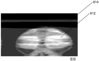
도 8a 는 저 복잡도 및 고 복잡도 이미지 데이터의 혼합을 갖는 예시적 이미지 (800) 를 예시한다. 예를 들어, 도 8a 에 예시된 바와 같이, 이미지 (800) 는 실질적 플랫 백그라운드 (802)(저 복잡도) 및 복잡한 포어그라운드 (804)(고 복잡도) 를 갖는다.8A illustrates an
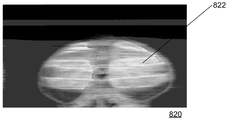
도 8b 는 고정된 최대 QP 값을 이용하여 이미지 (800) 의 상이한 공간적 영역들을 코딩함에 있어서 인코더 (20) 에 의해 이용될 수도 있는 QP 값들을 나타내는 QP 값 맵 (810) 을 예시한다. QP 값 맵 (810) 은 이미지 (800) 의 공간 영역들에 대응하는 더 밝은 영역들 (812) 을 포함할 수도 있고 여기에서 인코더 (20) 는 이들 영역들과 연관된 비디오 데이터의 블록들을 코딩하는데 있어서 더 높은 (higher) QP 값들을 이용한다. 추가로, QP 값 맵 (810) 의 더 어두운 영역들 (814) 이 이미지 (800) 의 공간 영역들에 대응하고, 여기에서, 인코더 (20) 는 이미지 (800) 의 영역을 코딩하는데 있어 더 낮은 (lower) QP 값들을 이용한다. 예를 들어, QP 값 맵 (810) 의 더 밝은 영역 (812) 은 이미지 (800) 의 복잡한 포어그라운드 (804) 에 대응할 수도 있고, 더 높은 QP 값들을 이용하여 인코더 (20) 에 의해 코딩되어, 더 큰 양의 양자화 손실을 야기할 수도 있다. 한편, QP 값 맵 (810) 의 더 어두운 영역 (814) 은 이미지 (800) 의 실질적으로 플랫한 백그라운드 (802) 에 대응할 수도 있고, 여기에서 인코더 (20) 는 비디오 데이터를 코딩하는데 있어 더 낮은 QP 값들을 이용한다.8B illustrates a
도 8c 는 이미지 (800) 의 상이한 공간 영역들을 코딩하는데 있어서 인코더 (20) 에 의해 이용될 수도 있는 QP 값을 나타내는 다른 QP 값 맵 (820) 을 예시하며, 여기에서 인코더 (20) 는 최대 QP 값을 동적으로 조정가능하다. 도 8c 에 예시된 바와 같이, 최대 QP 값을 동적으로 조정하는 것에 의해, 이미지에 걸친 평균 QP 값이 감소될 수도 있어, 이미지 품질을 가능성있게 개선하고 왜곡을 감소시킨다. 예를 들어, 이미지의 (QP 값 맵 (810) 의 영역 (812) 에 대응하는) 영역 (822) 을 코딩하는데 있어 인코더 (20) 에 의해 이용된 QP 값은, (도 8b 에 예시된 바와 같이) 고정된 최대 QP 값이 이용될 때에 비해 인코더 (20) 가 최대 QP 값을 동적으로 조정가능할 때 더 낮을 수도 있다.8C illustrates another
일부 실시형태들에서, 최대 QP 는 루미넌스 채널에만 대응하는 값을 지칭할 수도 있거나 또는 루미넌스 채널 및 크로미넌스 채널 양쪽을 지칭할 수도 있다. 대안으로서, 최대 QP 는 개별적인 루미넌스 및 크로미넌스 최대 QP 값들이 (예를 들어, 룩업 테이블 (LUT) 또는 다른 데이터 구조로부터) 계산 또는 추론되게 하는 마스터 최대 QP 값을 지칭할 수도 있다.In some embodiments, the maximum QP may refer to a value corresponding only to a luminance channel, or may refer to both a luminance channel and a chrominance channel. Alternatively, the maximum QP may refer to a master maximum QP value that causes individual luminance and chrominance maximum QP values to be calculated or deduced (e.g., from a look-up table (LUT) or other data structure).
일부 실시형태들에서, 레이트 제어기 (120) 는 (예를 들어, 버퍼 (150) 의 버퍼 충만도로서 측정된) 버퍼 (150) 에서의 복수의 비트들에 기초하여 최대 QP 를 조정할 수도 있다. 일부 실시형태들에서, 레이트 제어기 (120) 는 비디오 데이터의 이전에 코딩된 블록들의 복잡도 정보 (예를 들어, 복잡도 값) 에 기초하여 최대 QP 를 계산할 수도 있다. 예를 들어, 비디오 데이터의 이전에 코딩된 블록들이 고 복잡도 값들을 가지면, 레이트 제어기 (120) 는 더 높은 값으로 최대 QP 값을 조정할 수도 있어, 비디오 데이터의 후속 블록들이 더 적은 비트들을 이용하여 코딩될 수 있게 된다. 한편, 비디오 데이터의 이전에 코딩된 블록들이 저 복잡도 값들을 가지면, 레이트 제어기 (120) 는 더 낮은 값으로 최대 QP 값을 조정할 수도 있어, 비디오 데이터의 후속 블록들이 더 많은 수의 비트들을 이용하여 코딩될 수 있게 된다. 일부 실시형태들에서, 레이트 제어기 (120) 는 비디오 데이터의 하나 이상의 이전에 코딩된 블록들의 복잡도 값이 하나 이상의 임계 값들을 충족하는지의 여부의 결정에 기초하여 비디오 데이터의 현재 블록을 코딩하기 위하여 최대 QP 값을 조정하기 위한 양을 결정할 수도 있다. 일부 실시형태들에서 복잡도 정보는 플랫화도 검출기 (115) 에 의해 계산될 수도 있다.In some embodiments, the
일부 실시형태들에서, 비디오 데이터의 복잡도 값은 변환, 예를 들어, 하다마드, DCT 등을 이용하여 블록으로부터 도출될 수도 있다. 일부 실시형태들에서, 블록에 대한 복잡도 값은 블록을 코딩하는데 소모되는 복수의 비트들, 및 블록의 연관 QP 값 및 모드 정보 (예를 들어, 블록을 코딩하는데 이용된 코딩 모드) 에 기초하여 유도될 수도 있다.In some embodiments, the complexity value of the video data may be derived from the block using transforms, e.g., Hadamard, DCT, and the like. In some embodiments, the complexity value for the block is determined based on a plurality of bits consumed in coding the block, and an associated QP value of the block and mode information (e.g., the coding mode used to code the block) .
일부 실시형태들에서, 비디오 데이터의 하나 이상의 이전에 코딩된 블록들의 복잡도 값은 버퍼 (150) 의 버퍼 충만도로부터 추론될 수도 있다. 예를 들어, 일부 실시형태들에서, 버퍼 (150) 의 버퍼 충만도가 높을 때 (예를 들어, 버퍼 (150) 가 거의 차있을 때) 하나 이상의 이전에 코딩된 블록들이 고 복잡도 값을 갖는 것으로 추론될 수도 있다. 한편, 버퍼 (150) 의 버퍼 충만도가 낮을 때, 하나 이상의 이전에 코딩된 블록들이 저 복잡도 값을 갖는 것으로 추론될 수도 있다.In some embodiments, the complexity value of one or more previously coded blocks of video data may be deduced from the buffer fullness of buffer 150. [ For example, in some embodiments, one or more previously coded blocks have a high complexity value when the buffer fullness of the buffer 150 is high (e.g., when the buffer 150 is nearly full) It can be inferred. On the other hand, when the buffer fullness of the buffer 150 is low, one or more previously coded blocks may be deduced to have low complexity values.
일부 실시형태들에서, 레이트 제어기 (120) 는 최대 QP 값을 조정하도록 이전에 코딩된 블록들의 복잡도 값 및 버퍼 (150) 의 상태 (예를 들어, 버퍼 충만도) 양쪽을 이용할 수도 있다.In some embodiments,
일부 실시형태들에 따르면, maxFixedQp 는 인코더 (20) 에 의해 유지된 디폴트 최대 QP 값 (예를 들어, 미리 정해진 값) 을 표현할 수도 있는 한편, maxCalQp 는 (예를 들어, 레이트 제어기 (120) 에 의해) 조정된 최대 QP 값을 표현할 수도 있다. δ 는 maxFixedQp 을 조정하여 maxCalQp 를 결정하는데 이용되는 오프셋 값 (또한 조정 값으로서 지칭됨) 을 표기한다. 즉, 조정된 최대 QP 는 maxCalQp=maxFixedQp-δ 로서 계산될 수도 있다. 일부 실시형태들에서, δ 는 버퍼 (150) 의 버퍼 충만도 (BF) 에만 기초하여 결정된다. 다른 구현에서, 레이트 제어기 (120) 는 δ 오프셋 값을 유도하기 위해 하나 이상의 이전에 코딩된 블록들의 복잡도 값 및 BF 양쪽 모두를 결합할 수도 있다.According to some embodiments, maxFixedQp may represent a default maximum QP value (e.g., a predetermined value) maintained by
일부 실시형태들에서, BF 가 제 1 더 작은 임계값 (S n ) 과 제 2 더 큰 임계값 (L m ) 사이에 있을 때, S n <BF<L m 이도록, 레이트 제어기 (120) 는 maxCalQp 를 계산하기 위해 디폴트 비제로 양의 오프셋 값 δ=δ default >0 을 이용할 수도 있다. 예를 들어, 더 높은 값의 maxFixedQp 를 이용하는 대신에, 레이트 제어기 (120) 는 더 낮은 값의 maxCalQp 를 결정하도록 고정된 오프셋만큼 maxFixedQp 를 감소시키고, 이 maxCalQp 는 슬라이스에서의 연속하는 블록들을 인코딩하는데 이용될 수도 있다 (예를 들어, 슬라이스에서의 인코딩된 연속하는 블록들에 이용된 QP 값은 더 높은 maxFixedQp 대신에 더 낮은 maxCalQp 에 의해 제한될 수도 있다).In some embodiments, BF a first smaller threshold value (S n) and the second time is between the larger threshold value (L m), S n such that <BF <L m, the
위에 논의된 바와 같이, 버퍼 (150) 의 버퍼 충만도는 비디오 데이터의 블록들을 코딩하기 위해 인코더 (20) 에 의해 이용된 비트들의 수에 의해 영향을 받을 수도 있다. 예를 들어, 인코더 (20) 가 평균 수의 비트들을 이용하여 비디오 데이터의 블록들을 코딩중일 때, 버퍼 (150) 의 충만도는 실질적으로 일정하게 유지될 수도 있다. 한편, 인코더 (20) 가 평균 수 미만의 비트들을 이용하여 비디오 데이터의 블록들을 코딩중일 때, 버퍼 (150) 의 버퍼 충만도는 감소하기 시작할 수도 있다. 인코더 (20) 가 평균수 보다 더 많은 수의 비트들을 이용하여 비디오 데이터의 블록들을 코딩하고 있을 때, 버퍼 (150) 의 버퍼 충만도는 증가할 수도 있다.As discussed above, the buffer fullness of the buffer 150 may be affected by the number of bits used by the
일부 실시형태들에서, 인코더 (20) 가 예를 들어, 연속하는 블록들에서의 텍스처링된/복잡한 비주얼 정보에 기인하여 평균 수 보다 더 큰 수의 비트들을 이용하여 비디오 데이터의 연속하는 블록들에서의 비주얼 정보를 효과적으로 코딩하도록 계산된 maxCalQp 가 충분히 낮을 때, 버퍼 (150) 의 버퍼 충만도는 임계값 (L m ) 을 초과하여 증가할 수도 있다. 버퍼 충만도가 L m 의 임계값을 초과할 때, 레이트 제어기 (120) 는 δ default 값을 감소시키고, 감소된 오프셋 값을 이용하여 비디오 데이터의 다음 연속하는 블록들을 코딩하는데 있어 인코더 (20) 에 대한 새로운 maxCalQp 를 유도할 수도 있다. 이로써, maxCalQp 는 더 높게 되어, 인코더 (20) 가 더 높은 QP 값들로 비디오 데이터의 블록들을 인코딩하는 것을 허용한다. 이 새로운 최대 값이 추가의 증가된 버퍼 충만도를 가져오면, 감소된 오프셋 값은 추가로 감소된다. 레이트 제어기 (120) 는 버퍼 (150) 가 오버플로우하는 것을 방지하기 위하여 버퍼 충만도가 미리 정해진 임계값보다 더 낮아질 때까지 오프셋 값을 계속해서 감소시키고 maxCalQp 를 계산하는 단계들을 반복할 수도 있다. 특정 경우, 음의 오프셋은 버퍼가 오버플로우하는 것을 방지하도록 허용할 수도 있다.In some embodiments, the
한편, maxCalQp 가 (예를 들어, 인코더 (20) 가 평균 수 미만의 비트들을 이용하여 비디오 데이터의 연속하는 블록들에서의 비주얼 정보를 코딩하기에 maxCalQp 가 충분히 높은 것에 기인하여) 임계값 (S n ) 을 너머 감소하는 버퍼 충만도를 가져올 때, 레이트 제어기 (120) 는 오프셋 값을 증가시킬 수도 있어 maxCalQp 의 보다 낮은 값들을 가져온다. 더 낮은 maxCalQp 값들은 인코더 (20) 로 하여금 더 낮은 QP 값들을 이용하여 비디오 데이터의 블록들을, 따라서 더 많은 수의 비트들을 평균적으로 코딩하게 할 수도 있다. 일부 실시형태들에서, 오프셋 값은 버퍼 충만도가 임계값 (Sn) 미만으로 감소할 때 변경되지 않을 수도 있다.On the other hand, if maxCalQp is less than the threshold S n (for example, due to the fact that maxCalQp is sufficiently high for the
도 9 는 버퍼 충만도 (BF) 의 상이한 범위들에 대한 오프셋 델타 값을 선택하기 위한 예시적 방식의 그래프를 나타낸다. 일부 실시형태들에서, 레이트 제어기 (120) 는 복수의 상이한 버퍼 충만도 임계값들에 기초하여 maxCalQp 를 결정하기 위하여 오프셋 (δ) 을 조정할 수도 있다. 도 9 는 축의 좌측에 최소 값 (Min BF) 내지 축의 우측에 최대 값 (Max BF) 의 범위에 있는 버퍼 (150) 의 버퍼 충만도 값들에 대응하는 수평축을 예시한다. 복수의 임계값들은 n 개의 보다 작은 버퍼 값들 ([S 1 , S 2, … S n ]) 및 m 개의 보다 큰 버퍼 값들 ([L 1 , L 2 ,… L m ]) 을 포함하여, 수평축을 따라 위치된다. 임계 값들은 S1≤,S2≤,…≤Sn 및 L1≥,L2≥,…≥Lm≥Sn 이도록 배열된다.Figure 9 shows a graph of an exemplary scheme for selecting an offset delta value for different ranges of buffer fullness BF. In some embodiments, the
인접하는 임계값들의 각각의 쌍 ([S 1 , S 2, … S n ] 및 [L 1 , L 2 ,… L m ]) 은 maxCalQp 를 결정하기 위하여 레이트 제어기 (120) 에 의해 이용될 수도 있는 특정 오프셋 값과 연관된 버퍼 충만도 범위를 정의할 수도 있다. 예를 들어, Sn 과 Lm 사이의 버퍼 충만도 값들의 범위는 디폴트 오프셋 값 (δdefault) 과 연관될 수도 있다. 인접하는 더 작은 임계값들 ([S 1 , S 2, … S n ]) 에 의해 정의된 각각의 범위는 개별적인 오프셋 값 ([δ1″,δ2″,…,δn″]) 과 연관될 수도 있고, 여기서, δ1″≥ δ2″≥…≥δn″≥ δdefault 이다. 예를 들어, 도 9 에 예시된 바와 같이, 오프셋 값 δ1″ 는 Min BF 와 S 1 사이의 BF 값들의 범위와 연관되는 한편, 오프셋 값 δn″ 는 Sn-1 과 Sn 사이의 BF 값들의 범위와 연관된다.Each pair of threshold values which are adjacent ([S 1, S 2, ... S n] and [L 1, L 2, ... L m]) is which may be used by the
추가로, 인접하는 더 큰 임계값들 ([L 1 , L 2 ,… L m ]) 에 의해 정의된 각각의 범위는 개별적인 오프셋 값 ([δ1′,δ2′,…,δm′]) 과 연관될 수도 있고, 여기에서, δ1′≤ δ2′≤…≤δm′≤ δdefault 이다. 예를 들어, 도 9 에 예시된 바와 같이, 오프셋 값 δ1′ 는 L1 과 Max BF 사이의 BF 값들의 범위와 연관되는 한편, 오프셋 값 δm′ 는 L m 과 L m-1 사이의 BF 값들의 범위와 연관된다.In addition, each range defined by adjacent larger thresholds ([ L 1 , L 2 , ... L m ]) may be represented by an individual offset value ([δ 1 ', δ 2 ', ..., δ m ' ), ≪ / RTI > where < RTI ID = 0.0 > ≤ δ m '≤ δ default . For example, as illustrated in Figure 9, the offset values δ 1 'is L1 and that is associated with the range of BF value between Max BF On the other hand, the offset value δ m' is BF value between L m and L m-1 ≪ / RTI >
일부 실시형태들에서, 레이트 제어기 (120) 는 다음의 의사코드에 기초하여 버퍼 (150) 의 버퍼 충만도 (BF) 에 기초하여 최대 QP 를 조정하기 위한 오프셋 값 (δ) 을 계산할 수도 있다.In some embodiments, the
δ=δdefault;δ = δ default ;
(BF >= L 1 )이면(BF > = L 1 )
![]()
![]()
그렇지 않고 (BF >= L 2 ) 이면Otherwise (BF > = L 2 )
![]()
![]()
......
그렇지 않고 (BF >= L m ) 이면Otherwise (BF > = L m )
![]()
![]()
(BF <= ![]()
![]()
![]()
![]()
그렇지 않고 (BF <= ![]()
![]()
![]()
![]()
......
그렇지 않고 (BF <= ![]()
![]()
![]()
![]()
위에 논의된 바와 같이, 레이트 제어기 (120) 는 오프셋 값 (δ) 을 이용하여 최대 QP 값을 maxCalQp=maxFixedQp-δ 로서 조정할 수도 있다. 위의 구현에서, "이하" 의 지정은 엄격하게 "미만" 으로 대체될 수 있다. 이와 유사하게, "이상"의 지정은 엄격하게 "초과" 로 대체될 수 있다. 일부 실시형태들에서, n 과 m 은 동일할 수도 있거나 동일하지 않을 수도 있다.As discussed above, the
이와 같이, 도 9 에서 위에 설명된 바와 같이, 버퍼 (150) 의 버퍼 충만도가 낮을 때 (예를 들어, S n 보다 낮을 때), 레이트 제어기 (120) 는 오프셋 (δ) 의 값을 δdefault 보다 더 높은 값으로 설정하여, 더 낮은 maxCalQp 를 가져올 수도 있다. 이로써, 인코더 (20) 는 버퍼 (150) 의 충만도를 가능성있게 증가시키는 보다 큰 수의 비트들을 이용하여 비디오 데이터의 연속적인 블록들을 코딩할 수도 있다.9, when the buffer fullness of the buffer 150 is low (for example, lower than S n ), the
한편, 버퍼 (150) 의 버퍼 충만도가 높을 때 (예를 들어, L m 을 초과할 때), 레이트 제어기 (120) 는 오프셋 (δ) 의 값을 δdefault 보다 더 낮은 값으로 설정하여, 더 높은 maxCalQp 를 가져올 수도 있다. 이로써, 인코더 (20) 는 버퍼 (150) 의 충만도를 가능성있게 감소시키는 보다 적은 수의 비트들을 이용하여 비디오 데이터의 연속적인 블록들을 코딩할 수도 있다.On the other hand, when the buffer fullness of the buffer 150 is high (e.g., exceeds L m ), the
일부 실시형태들에서, 버퍼 임계값들 ([L 1 , L 2 ,… L m ] 및/또는 [S 1 , S 2, … S n ]) 은 루마 및 크로마 컴포넌트 양쪽 모두에 대해 동일할 수도 있다. 다른 구현에서, 이들은 루마 및 크로마 컴포넌트들에 대해 상이할 수도 있다. 다른 예에서, 각각의 버퍼 임계값에 대한 오프셋 값 (δ) 은 루마 및 크로마 컴포넌트에 대하여 동일 또는 상이할 수도 있다.In some embodiments, the buffer thresholds ([ L 1 , L 2 , ... L m ] and / or [ S 1 , S 2, ... S n ]) may be the same for both luma and chroma components . In other implementations, these may be different for luma and chroma components. In another example, the offset value [delta] for each buffer threshold may be the same or different for the luma and chroma components.
임계값들 ([L 1 , L 2 ,… L m ]) 은 위에 논의된 바와 같이, QP 모드들 [Q 1 , Q 2 ,… Q m ] 을 결정하기 위해 이용된 동일한 m 개의 임계값들일 수도 있거나 아닐 수도 있다. 이와 유사하게, 임계값들 ([S 1 , S 2, … S n ]) 은 QP 모드들 [P 1 , P 2 ,… P m ] 을 결정하기 위해 이용된 동일한 n 개의 임계값들일 수도 있거나 아닐 수도 있다.The thresholds ([ L 1 , L 2 , ... L m ]) can be calculated using QP modes [ Q 1 , Q 2 , ... L m ] Lt; RTI ID = 0.0 > ; Qm ]. ≪ / RTI > Similarly, the thresholds [ S 1 , S 2, ... S n ] are used to determine the QP modes [ P 1 , P 2 , ... Lt ; RTI ID = 0.0 & gt ; Pm ]. ≪ / RTI >
일부 실시형태들에서, 하나 이상의 버퍼 충만도 임계 값들에 기초하여 최대 QP 를 조정하기 위한 오프셋 델타 값을 결정하는 대신에, 레이트 제어기 (120) 는 미리 정해진 함수 또는 식에 기초하여 버퍼 (150) 의 현재 버퍼 충만도 (BF) 로부터 오프셋 델타 값을 결정할 수도 있다.In some embodiments, instead of determining an offset delta value for adjusting the maximum QP based on one or more buffer fullness thresholds, the
일부 실시형태들에서, 최대 QP 를 조정하는데 이용된 오프셋 델타 값은 주기적으로 (예를 들어, 특정 시구간에서, 특정 수의 블록들이 코딩된 후에 등) 결정될 수도 있다. 예를 들어, 레이트 제어기 (120) 는 버퍼 (150) 의 현재 버퍼 충만도에 기초하여 인코더 (20) 에 의해 코딩될 비디오 데이터의 각각의 블록마다 최대 QP 를 조정하기 위한 오프셋 델타 값을 결정할 수도 있다.In some embodiments, the offset delta value used to adjust the maximum QP may be determined periodically (e.g., after a certain number of blocks have been coded, at a particular time interval, etc.). For example, the
본원에 개시된 기법들은 인코더 (20) 에서만 적용될 수도 있다. 예를 들어, 인코더 (20) 는 최대 QP 를 조정하기 위한 오프셋 값을 결정하고, 디코더 (30) 에 결정된 오프셋을 (예를 들어, 링크 (16) 를 통하여 디코더 (30) 에 송신된 코딩된 비디오 데이터 비트스트림의 부분으로서) 시그널링할 수도 있다. 다른 대안으로서, 본원에 제안된 기법들은 인코더 (20) 와 디코더 (30) 양쪽에 적용될 수 있다. 본원에 제안된 기법이 인코더 (20) 와 디코더 (30) 양쪽에 적용된 후의 일부 실시형태들에서, 인코더 (20) 는 디코더 (30) 에 오프셋 값을 시그널링할 필요가 없다.The techniques disclosed herein may only be applied to the
예시적인 실시형태Exemplary embodiments
도 10 은 버퍼 충만도 (BF) 의 상이한 범위들에 대한 오프셋 델타 값을 선택하기 위한 예시적 방식의 그래프를 나타낸다. 도 10 에 예시된 그래프는 도 9 에 예시된 그래프와 유사하며, 버퍼 (150) 의 버퍼 충만도 값들은 축의 좌측에 최소 BF (Min BF) 내지 축의 우측에 최대 BF (Max BF) 의 범위에 있는 수평축 상에 도시된다. 일부 실시형태들에서, 축 상에 표현된 BF 값들은 백분율 값들에 대응할 수도 있다. 예를 들어, Min BF 는 0% 에 대응할 수도 있고, Max BF 는 100% 에 대응할 수도 있다. 추가로, 도 9 에서와 같이, 도 10 의 그래프는 수평축을 따라 위치된 복수의 임계 값들을 나타낸다. 도 10 에 예시된 방식에서, 레이트 제어기 (120) 는 [12, 24] 의 값들을 갖는 n= 2 의 보다 작은 임계 값들 [S 1 , S 2 ] (수평 축의 좌측에 도시됨), 및 [88, 76] 의 값들을 갖는 m= 2 의 보다 큰 임계값들 [L 1 , L 2 ] (수평 축의 우측에 도시됨) 을 유지할 수도 있다.Figure 10 shows a graph of an exemplary scheme for selecting an offset delta value for different ranges of buffer fullness BF. The graph illustrated in FIG. 10 is similar to the graph illustrated in FIG. 9, wherein the buffer fullness values of the buffer 150 are in the range of a minimum BF (Min BF) to the left of the axis to a maximum BF (Max BF) Is shown on the horizontal axis. In some embodiments, the BF values represented on the axis may correspond to percent values. For example, Min BF may correspond to 0%, and Max BF may correspond to 100%. Further, as in FIG. 9, the graph of FIG. 10 shows a plurality of threshold values located along the horizontal axis. In the manner illustrated in Figure 10, the
버퍼 충만도를 표현하는 수평 축을 따르는 인접하는 임계값들의 각각의 쌍은 최대 QP 를 조정하기 위하여 레이트 제어기 (120) 에 의해 이용가능한 특정 오프셋 값에 대응할 수도 있다. 예를 들어, 버퍼 (150) 의 버퍼 충만도가 24% 와 76% 사이에 있을 때, 레이트 제어기 (120) 는 δdefault=4 의 오프셋 만큼 최대 QP 를 조정할 수도 있다. 버퍼 충만도가 76% 및 88% 일 때, 오프셋은 δ2′=2 일 수도 있다. 버퍼 충만도가 88% 위에 있을 때, 레이트 제어기 (120) 는 δ1′=0 의 오프셋을 이용할 수도 있다.Each pair of adjacent thresholds along the horizontal axis representing the buffer fullness may correspond to a particular offset value available by the
한편, 도 9 에 예시된 실시형태에서, 버퍼 충만도가 24 의 임계값 미만으로 감소할 때 오프셋 값은 감소하지 않을 수도 있다. 예를 들어, 12 미만의 버퍼 충만도 범위들에 대응할 수도 있는 오프셋들 δ1″ 및 δ2″ 은 각각, 4 의 값에 양쪽이 대응할 수도 있다. 임계값들 [L 1 , L 2 ] 및 [S 1 , S 2 ] 은 루마 및 크로마 채널 양쪽에 대해 동일할 수도 있다.On the other hand, in the embodiment illustrated in FIG. 9, the offset value may not decrease when the buffer fullness decreases below the threshold of 24. For example, offsets [delta] l " and delta 2 " that may correspond to ranges of buffer fullness less than 12 may correspond to a value of four, respectively. The thresholds [ L 1 , L 2 ] and [ S 1 , S 2 ] may be the same for both luma and chroma channels.
픽처 파라미터들에 기초한 Max QP 에 대한 조정들Adjustments for Max QP based on picture parameters
일부 실시형태들에서, 레이트 제어기 (120) 는 추가로 코딩될 비디오 데이터와 연관된 하나 이상의 픽처 파라미터들 (예를 들어, 소스 비트 심도, 압축 비트레이트 등) 에 기초하여 max QP 를 추가로 조정할 수도 있다. 예를 들어, 일부 실시형태들에서, 비디오 데이터의 소스 비트 심도에 대한 디폴트 값은 예를 들어, 컴포넌트마다 8 비트들일 수도 있다. 이러한 경우, max QP 가 다음과 같이 조정될 수도 있다:In some embodiments, the
maxQp=maxQp+((bitDepth-8)≪a)maxQp = maxQp + ((bitDepth-8) " a)
여기에서, 파라미터는 튜닝될 수도 있다 (예를 들어, 파라미터는 레이트 제어기 (120) 에 의해 수정될 수도 있다). 예를 들어, 어드밴스드 DSC (Advanced DSC; A-DSC) 에서, a=2 의 디폴트 값이 이용될 수도 있다.Here, the parameter may be tuned (e.g., the parameter may be modified by the rate controller 120). For example, in Advanced DSC (A-DSC), a default value of a = 2 may be used.
다른 실시형태들에서, max QP 에 대한 위의 식은 소스 비트 심도에 대한 디폴트 값에서의 변동들에 기초하여 수정될 수도 있다. 예를 들어, 식은 아래와 같이 수정될 수도 있고 여기에서 파라미터 (bd) 는 디폴트 비트 심도 값 (예를 들어, 컴포넌트 마다 비트들의 디폴트 수) 을 표시할 수도 있다.In other embodiments, the above equation for max QP may be modified based on variations in the default value for the source bit depth. For example, the expression may be modified as follows, where the parameter bd may represent a default bit depth value (e.g., the default number of bits per component).
maxQp=maxQp+((bitDepth-bd)≪a)maxQp = maxQp + ((bitDepth-bd) " a)
일부 실시형태들에서, 레이트 제어기 (120) 는 압축된 비트레이트 값에 기초하여 max QP 를 조정할 수도 있다. 다른 실시형태들에서, 레이트 제어기 (120) 는 압축된 비트레이트 또는 비트 심도 중 적어도 하나에 기초하여 max QP 를 조정할 수도 있다.In some embodiments, the
일부 실시형태들에서, 디폴트된 압축된 비트레이트는 6 bpp (8 bpc 소스 컨텐츠에 대해 4:1 압축) 일 수도 있다. A-DSC 코덱에서, 압축된 비트레이트는 m 개의 부분 비트들을 이용하여 정의될 수 있고, 이는 6 bpp 의 압축된 비트레이트가 (6≪m) 으로서 내부적으로 저장될 것임을 의미한다. 예를 들어, m = 4 일 때, 내부적으로 저장된 값은 6<<4 = 96 일 수도 있다.In some embodiments, the default compressed bit rate may be 6 bpp (4: 1 compression for 8 bpc source content). In the A-DSC codec, the compressed bit rate can be defined using m partial bits, which means that the compressed bit rate of 6 bpp will be stored internally as (6m). For example, when m = 4, the internally stored value may be 6 << 4 = 96.
디폴트 압축된 비트레이트가 6 bpp 와 동일하다고 보는 일부 실시형태들에서, 6bpp 미만의 값을 갖는 압축된 비트레이트에 대해, 레이트 제어기 (120) 는 다음과 같이 max QP 를 조정할 수도 있다.In some embodiments where the default compressed bit rate is equal to 6 bpp, for a compressed bit rate with a value less than 6 bpp, the
maxQp=maxQp+(((96-bpp)≫m)≪b0)maxQp = maxQp + (((96 -bpp) »m) «b 0)
이와 반대로, 6bpp 위의 비트레이트에 대해, 레이트 제어기 (120) 는 다음과 같이 max QP 를 조정할 수도 있다:Conversely, for a bit rate above 6 bpp, the
maxQp=maxQp-(((bpp-96)≫m)≪b1)maxQp = maxQp - (((bpp-96) <
여기에서, b0 및 b1 은 오프셋 양을 maxQp 로 스케일링하는 미리 정해진 고정된 값들에 대응할 수도 있다. 일부 실시형태들에서, m, b0, 및 b1 의 값들은 m=4,b0=3,b1=2 일 수도 있다. 다른 실시형태들에서, max QP 에 대하여 위의 식들은 디폴트 압축된 비트레이트 값에서의 변동들에 기초하여 수정될 수도 있다.Here, b 0 and b 1 may correspond to predetermined fixed values that scale the amount of offset to max Qp. In some embodiments, the values of m, b 0 , and b 1 may be m = 4, b 0 = 3, b 1 = 2. In other embodiments, the above equations for max QP may be modified based on variations in the default compressed bit rate value.
소스 비트 심도 및 압축된 비트레이트 양쪽이 이들의 디폴트 값들 (예를 들어, 각각 8 bpc 및 6 bpp) 과는 상이한 일부 실시형태들에서, 레이트 제어기 (120) 는 다음과 같이 (순서적으로 반드시 이러할 필요가 있는 것은 아님) max QP 를 2 배로 조정할 수도 있다.In some embodiments in which both the source bit depth and the compressed bit rate are different from their default values (e.g., 8 bpc and 6 bpp, respectively), the
![]()
![]()
![]()
![]()
일부 실시형태들에서, 픽처 파라미터들에 기초하여 max QP 를 조정한 후, 레이트 제어기 (120) 는 (예를 들어, 버퍼 (150) 의 버퍼 충만도에 기초하여) 이전의 섹션에서 설명된 기법을 이용하여 코더에 의해 온 더 플라이 방식으로 max QP 를 동적으로 추가로 조정할 수도 있다. 예를 들어, 일부 실시형태들에서, 레이트 제어기 (120) 는 소스 비트 심도 및 압축된 비트 레이트와 같은 픽처 파라미터들에 기초하여 max QP 값을 초기에 조정할 수도 있다. 조정된 max QP 값은 버퍼 (150) 의 버퍼 충만도에 기초하여 온 더 플라이 방식으로 max QP 값을 조정하는 목적을 위하여 maxFixedQp 값으로서 이용될 수도 있다.In some embodiments, after adjusting the max QP based on the picture parameters, the
프로세스 플로우Process flow
도 11 은 비디오 데이터의 블록들을 코딩하기 위한 최대 QP 값을 조정하는 예시적 프로세스의 플로우차트를 나타낸다. 블록 1102 에서, 레이트 제어기 (120) 는 디폴트 최대 QP 값을 결정할 수도 있다. 일부 실시형태들에서, 최대 QP 값은 미리 정해진 값일 수도 있다.11 shows a flowchart of an exemplary process for adjusting a maximum QP value for coding blocks of video data. At
블록 1104 에서, 레이트 제어기 (120) 는 하나 이상의 픽처 파라미터들에 기초하여 최대 QP 값을 조정할 수도 있다. 일부 실시형태들에서, 픽처 파라미터들은 소스 비트 심도 또는 압축된 비트레이트에 대응할 수도 있다. 일부 실시형태들에서, 레이트 제어기 (120) 는 먼저 소스 비트 심도에 기초한 다음 압축된 비트레이트에 기초하여 최대 QP 값을 조정할 수도 있다. 일부 실시형태들에서, 레이트 제어기 (120) 는 소스 비트 심도에만 기초하여 또는 압축된 비트레이트에만 기초하여 최대 QP 값을 조정할 수도 있다. 일부 실시형태들에서, 레이트 제어기 (120) 는 소스 비트 심도 또는 압축된 비트레이트가 디폴트 값으로부터 벗어나면, 소스 비트 심도 또는 압축된 비트레이트에 기초하여 최대 QP 값을 단지 조정할 수도 있다. 일부 실시형태들에서, 조정된 최대 QP 값은 maxFixedQp 값으로서 지칭될 수도 있다.At
블록 1106 에서, 레이트 제어기 (120) 는 버퍼 (150) 의 버퍼 충만도의 양의 표시를 수신할 수도 있다. 블록 1108 에서, 레이트 제어기는 버퍼의 버퍼 충만도에 기초하여 최대 QP 오프셋을 결정할 수도 있다. 일부 실시형태들에서, 레이트 제어기 (120) 는 오프셋 값을 결정하기 위해 하나 이상의 임계 값들에 대비하여 버퍼 충만도 값을 비교한다. 예를 들어, 하나 이상의 임계값들은 하나 이상의 버퍼 충만도 범위들을 정의할 수도 있고, 여기에서 상이한 오프셋 값들이 상이한 버퍼 충만도 값들과 연관될 수도 있다. 블록 1110 에서, 레이트 제어기 (120) 는 조정된 최대 QP (예를 들어 블록 1104 에서 결정된 maxFixedQp) 및 결정된 오프셋 값에 기초하여 최대 QP 값을 결정할 수도 있다. 예를 들어 레이트 제어기 (120) 는 maxFixedQp 와 결정된 오프셋 값 사이의 차이로서 최대 QP 값 (maxCalQp) 을 결정할 수도 있다. 결정된 최대 QP 값은 그 후, 비디오 데이터의 블록들을 코딩하는데 있어 인코더 (20) 에 의해 이용된다.At block 1106, the
일부 실시형태들에서, 블록들 1106 내지 1110 은 인코더 (20) 가 비디오 데이터의 연속하는 블록들을 코딩할 때마다 반복할 수도 있다. 예를 들어, 일부 실시형태들에서, 레이트 제어기 (120) 는 주기적 간격들로 (예를 들어, 특정 시구간들에서 또는 특정 수의 블록들이 코딩된 후) 버퍼 충만도의 표시자들을 수신할 수도 있다 (블록 1106). 레이트 제어기 (120) 는 그 후, 비디오 데이터의 후속 블록들을 코딩하기 위하여 인코더 (20) 에 의해 이용될 새로운 오프셋 및 최대 QP 값 (블록 1108, 1110) 을 결정할 수도 있다. 이 루프는 인코더 (20) 가 비디오 데이터의 모든 블록들을 코딩할 때까지 반복할 수도 있다.In some embodiments, blocks 1106 through 1110 may be repeated each
버퍼 충만도에 기초하여 비디오 데이터의 블록들을 코딩하는데 이용된 최대 QP 값을 동적으로 조정하는 것에 의해 레이트 제어기 (120) 는 버퍼 (150) 가 비어 있는 상태로 되거나 오버플로우하는 것을 방지하면서 비디오 데이터의 블록들을 코딩하는데 이용된 최대 QP 값을 가능성있게 제한할 수도 있다. 예를 들어, 버퍼 충만도가 낮을 때 (예를 들어, 특정 임계값들 미만일 때) 오프셋 값을 증가시키는 것 (그리고 이에 따라 최대 QP 값을 감소시키는 것) 에 의해, 인코더 (20) 는 인코더가 달리 이용할 수도 있었던 것보다 더 작은 QP 값을 이용하여 비디오 데이터의 블록들을 인코딩하여, 양자화 손실들을 감소시키고 버퍼가 빈 상태가 되는 것을 방지한다.By dynamically adjusting the maximum QP value used to code the blocks of video data based on the buffer fullness, the
본원에 개시된 정보 및 신호들은 다양한 상이한 기술들 및 기법들 중 임의의 것을 이용하여 표현될 수도 있다. 예를 들어, 설명을 통해 참조될 수도 있는 데이터, 명령들, 커맨드들, 정보, 신호들, 비트들, 심볼들, 및 칩들은 전압들, 전류들, 전자기파들, 자기장들 또는 자기 입자들, 광학 필드들 또는 입자들, 이들의 임의의 조합에 의해 표현될 수도 있다.The information and signals disclosed herein may be represented using any of a variety of different techniques and techniques. For example, data, instructions, commands, information, signals, bits, symbols, and chips that may be referenced throughout the description may include voltages, currents, electromagnetic waves, magnetic fields or magnetic particles, Fields or particles, or any combination thereof.
당업자라면, 본원에서 개시된 실시형태들과 연계하여 설명된 다양한 예시적인 논리 블록들 및 알고리즘 단계들이 전자 하드웨어, 컴퓨터 소프트웨어, 또는 이들 양자 모두의 조합들로서 구현될 수도 있다. 하드웨어 및 소프트웨어의 이러한 상호 교환성을 명확하게 설명하기 위해, 여러 예증적인 컴포넌트들, 블록들 및 단계들을 그들의 기능적 관점에서 설명하였다. 그러한 기능이 하드웨어 또는 소프트웨어로 구현되는지 여부는 특정 애플리케이션 및 전체 시스템에 부과되는 설계 제약들에 따라 달라진다. 당업자들은 각각의 특정 애플리케이션을 위해 다양한 방식들로 설명된 기능을 구현할 수도 있으나, 그러한 구현 결정들이 본 개시의 범위로부터 벗어나게 하는 것으로 해석되어서는 안된다.Those skilled in the art will appreciate that the various illustrative logical blocks and algorithms described in connection with the embodiments disclosed herein may be implemented as electronic hardware, computer software, or combinations of both. In order to clearly illustrate this interchangeability of hardware and software, various illustrative components, blocks, and steps have been described in terms of their functionality. Whether such functionality is implemented as hardware or software depends upon the particular application and design constraints imposed on the overall system. Skilled artisans may implement the described functionality in varying ways for each particular application, but such implementation decisions should not be interpreted as causing a departure from the scope of the present disclosure.
따라서, 본원에서 설명된 기능들은 하드웨어, 소프트웨어, 펌웨어, 또는 이들의 임의의 조합으로 구현될 수도 있다. 이러한 기술은 무선 통신 디바이스 핸드셋, 자동차, 가전기기, 웨어러블 및/또는 다른 디바이스들에서의 애플리케이션을 포함하는 다수의 용도를 갖는, 범용 컴퓨터, 무선 통신 디바이스 핸드셋, 또는 집적 회로 디바이스들과 같은 다양한 디바이스들 중 어느 것에서 구현될 수도 있다. 디바이스들 또는 컴포넌트들로서 설명된 임의의 피쳐들은 집적된 로직 디바이스에서 함께 또는 별개이지만 상호 연동이 가능한 (interoperable) 로직 디바이스들로서 개별적으로 구현될 수도 있다. 소프트웨어로 구현되면, 상기 기법들은, 실행시 상술한 방법들의 적어도 하나를 수행하는 명령들을 포함하는 컴퓨터 판독가능 저장 매체에 의해 적어도 부분적으로 실현될 수도 있다. 컴퓨터 판독가능 데이터 저장 매체는 컴퓨터 프로그램 제품의 일부를 형성할 수도 있고, 컴퓨터 프로그램 제품은 포장재료들을 포함할 수도 있다. 컴퓨터 판독가능 매체는 유형의 컴퓨터 판독가능 저장 매체, 예컨대 SDRMA (synchronous dynamic random access memory) 과 같은 RAM (random access memory), ROM (read-only memory), NVRAM (non-volatile random access memory), EEPROM (electrically erasable programmable read-only memory), 플래시 메모리, 자기 또는 광학 데이터 저장 매체 등을 포함할 수도 있다. 상기 기술들은, 추가적으로, 또는 대안적으로, 명령들 또는 데이터 구조들의 형태의 코드를 전달 또는 통신하며 컴퓨터에 의해 액세스, 판독, 및/또는 실행될 수 있는 컴퓨터 판독가능 통신 매체에 의해 적어도 부분적으로 실현될 수도 있다.Thus, the functions described herein may be implemented in hardware, software, firmware, or any combination thereof. Such techniques may be used in a variety of devices, such as a general purpose computer, a wireless communication device handset, or integrated circuit devices, with multiple uses including applications in wireless communication device handsets, automotive, consumer electronics, wearable and / ≪ / RTI > Any of the features described as devices or components may be implemented separately in logic devices that are interoperable or separate but interoperable in an integrated logic device. If implemented in software, the techniques may be at least partially realized by a computer-readable storage medium including instructions that, when executed, perform at least one of the methods described above. The computer readable data carrier may form part of a computer program product, which may include packaging materials. The computer-readable medium may be any type of computer-readable storage medium, such as random access memory (RAM), read-only memory (ROM), non-volatile random access memory (NVRAM), EEPROM (electrically erasable programmable read-only memory), flash memory, magnetic or optical data storage media, and the like. The techniques may additionally or alternatively be implemented at least in part by a computer readable communication medium that can communicate or communicate code in the form of instructions or data structures and which may be accessed, read, and / or executed by a computer It is possible.
하나 이상의 디지털 신호 프로세서 (digital signal processor; DSP) 들, 범용 마이크로프로세서들, ASIC (application specification integrated circuit), FPGA (field programmable gate array), 또는 임의의 다른 균등의 분산 또는 집적 로직 회로부와 같은 하나 이상의 프로세서들을 포함할 수도 있는 프로세서에 의해 프로그램 코드가 실행될 수도 있다. 이러한 프로세서는 본 개시에서 설명되는 기술들 중 어느 것을 수행하도록 구성될 수도 있다. 범용 프로세서는 마이크로프로세서일 수도 있지만, 대안으로, 프로세서는 임의의 통상의 프로세서, 제어기, 마이크로컨트롤러, 또는 상태 머신일 수도 있다. 프로세서는 또한 컴퓨팅 디바이스들의 조합, 예를 들면, DSP와 마이크로프로세서의 조합, 복수의 마이크로프로세서들, DSP 코어와 연계한 하나 이상의 마이크로프로세서들, 또는 임의의 다른 그러한 구성으로 구현될 수도 있다. 따라서, 본원에서 이용되는 바와 같은 용어 "프로세서" 는 앞서 언급한 구조, 또는 본원에서 설명된 기법들을 구현하기에 적합한 임의의 다른 구조 또는 장치의 임의의 조합을 지칭할 수도 있다. 또한, 몇몇 양태들에서, 본원에서 사용된 기능은, 인코딩 및 디코딩을 위해 구성된 전용 소프트웨어 또는 하드웨어 내에서 제공되거나, 또는 결합된 비디오 인코더-디코더 (CODEC) 에 통합될 수도 있다. 또한, 상기 기술들은 하나 이상의 회로들 또는 로직 소자들에서 완전히 구현될 수 있다.Such as one or more digital signal processors (DSPs), general purpose microprocessors, application specification integrated circuits (ASICs), field programmable gate arrays (FPGAs), or any other equivalent distributed or integrated logic circuitry. The program code may be executed by a processor that may include processors. Such a processor may be configured to perform any of the techniques described in this disclosure. A general purpose processor may be a microprocessor, but, in the alternative, the processor may be any conventional processor, controller, microcontroller, or state machine. The processor may also be implemented in a combination of computing devices, e.g., a combination of a DSP and a microprocessor, a plurality of microprocessors, one or more microprocessors in conjunction with a DSP core, or any other such configuration. Thus, the term " processor " as used herein may refer to any of the above-mentioned structures, or any other structure or device suitable for implementing the techniques described herein. Also, in some aspects, the functions used herein may be provided in dedicated software or hardware configured for encoding and decoding, or may be incorporated in a combined video encoder-decoder (CODEC). In addition, the techniques may be fully implemented in one or more circuits or logic elements.
본 개시의 기술들은, 무선 헤드셋, 집적 회로(IC) 또는 ICs의 세트 (예를 들면, 칩세트) 를 포함하는 다양한 디바이스들 또는 장치들에서 구현될 수도 있다. 개시된 기술들을 수행하도록 구성된 디바이스들의 기능적 양태를 강조하기 위해 다양한 소자들, 모듈들, 또는 유닛들이 본 개시에서 설명되었지만, 반드시 상이한 하드웨어 유닛들에 의해 실현될 필요는 없다. 대신, 상술한 바와 같이, 다양한 유닛들은, 적절한 소프트웨어 및/또는 펌웨어와 연계하여, 코덱 하드웨어 유닛에 통합되거나 또는 상술한 하나 이상의 프로세서들을 포함하여 상호 동작적인 하드웨어 유닛들의 집합에 의해 제공될 수도 있다.The techniques of the present disclosure may be implemented in a variety of devices or devices including a wireless headset, an integrated circuit (IC) or a set of ICs (e.g., a chipset). Although various elements, modules, or units have been described in this disclosure to emphasize the functional aspects of the devices configured to perform the disclosed techniques, they need not necessarily be realized by different hardware units. Instead, as described above, the various units may be provided by a set of interoperable hardware units, either integrated into the codec hardware unit or in conjunction with one or more processors as described above, in conjunction with appropriate software and / or firmware.
상술한 설명은 여러 상이한 실시형태들과 연계하여 설명되었지만, 일 실시형태로부터의 피처들 또는 엘리먼트들이 이 개시의 교시에 벗어남이 없이 다른 실시형태들과 결합될 수도 있다. 그러나, 개개의 실시형태들 간의 피처들의 조합은 반드시 이들로 한정되는 것은 아니다. 본 개시의 여러 양태들이 설명되었다. 이들 및 다른 실시형태들은 하기의 청구범위의 범위 내에 있다.Although the foregoing description has been described in connection with various different embodiments, it is to be understood that the features or elements from one embodiment may be combined with other embodiments without departing from the teachings of this disclosure. However, the combination of features between the individual embodiments is not necessarily limited to these. Various aspects of the present disclosure have been described. These and other embodiments are within the scope of the following claims.
Claims (27)
코딩된 비디오 정보를 저장하도록 구성된 버퍼 유닛; 및
하드웨어 프로세서를 포함하고,
상기 하드웨어 프로세서는:
상기 버퍼 유닛의 버퍼 충만도를 결정하는 것으로서, 상기 버퍼 충만도는 상기 버퍼 유닛에서 현재 점유된 비트들의 수와 상기 버퍼 유닛의 현재 용량 사이의 비를 나타내는, 상기 버퍼 충만도를 결정하고;
초기 최대 양자화 파라미터 (quantization parameter; QP) 값을 결정하고;
상기 버퍼 유닛의 결정된 상기 버퍼 충만도에 적어도 부분적으로 기초하여 조정 값을 결정하고;
결정된 상기 조정 값을 이용하여 초기 최대 QP 값을 조정하는 것으로서, 조정된 상기 최대 QP 값은 상기 비디오 정보의 현재 블록을 코딩하는데 이용될 수도 있는 최대 QP 값을 특정하는, 상기 초기 최대 QP 값을 조정하고; 그리고
QP 값이 상기 조정된 최대 QP 값을 초과하지 않을 수도 있다는 제약에 따라, 디스플레이 또는 송신을 위하여 비디오 데이터 비트스트림을 형성하도록 상기 QP 값에 기초하여 상기 비디오 정보의 현재 블록을 코딩하도록 구성되는, 비디오 정보를 코딩하기 위한 장치.An apparatus for coding video information,
A buffer unit configured to store coded video information; And
Hardware processor,
The hardware processor comprising:
Determining a buffer fullness of the buffer unit, the buffer fullness indicating a ratio between a number of currently occupied bits in the buffer unit and a current capacity of the buffer unit;
Determining an initial maximum quantization parameter (QP) value;
Determine an adjustment value based at least in part on the determined buffer fullness of the buffer unit;
Adjusting the initial maximum QP value using the determined adjustment value, wherein the adjusted maximum QP value specifies a maximum QP value that may be used to code the current block of video information, and; And
And adapted to code a current block of video information based on the QP value to form a video data bit stream for display or transmission, subject to a constraint that the QP value may not exceed the adjusted maximum QP value. Apparatus for coding information.
상기 하드웨어 프로세서는 또한, 상기 버퍼 유닛의 상기 버퍼 충만도가, 더 높은 제 1 충만도 임계값과 더 낮은 제 2 충만도 임계값 사이의 레벨에 있을 때 상기 조정 값을 디폴트 조정 값으로 설정하도록 구성되고, 상기 디폴트 조정 값은 0 보다 큰, 비디오 정보를 코딩하기 위한 장치.The method according to claim 1,
The hardware processor is further configured to set the adjustment value to a default adjustment value when the buffer fullness of the buffer unit is at a level between a higher first fullness threshold and a lower second fullness threshold And wherein the default adjustment value is greater than zero.
상기 하드웨어 프로세서는 또한, 상기 버퍼 유닛의 상기 버퍼 충만도가 상기 제 2 충만도 임계값보다 더 낮은 상태에서는, 상기 조정 값을 상기 디폴트 조정 값보다 더 높은 값으로 설정하도록 구성되는, 비디오 정보를 코딩하기 위한 장치.3. The method of claim 2,
Wherein the hardware processor is further configured to set the adjustment value to a value higher than the default adjustment value when the buffer fullness of the buffer unit is lower than the second fullness threshold, / RTI >
상기 하드웨어 프로세서는 또한, 상기 버퍼 유닛의 상기 버퍼 충만도가 상기 제 1 충만도 임계값보다 더 높은 상태에서는, 상기 조정 값을 상기 디폴트 조정 값보다 더 낮은 값으로 설정하도록 구성되는, 비디오 정보를 코딩하기 위한 장치.3. The method of claim 2,
Wherein the hardware processor is further configured to set the adjustment value to a value lower than the default adjustment value when the buffer fullness of the buffer unit is higher than the first fullness threshold, / RTI >
상기 하드웨어 프로세서는 또한, 비디오 정보의 이전 블록을 코딩하는데 소비된 비트들의 수에 적어도 부분적으로 기초하여 유도된 복잡도 값을 결정하도록 구성되고, 상기 조정 값은 또한 결정된 상기 복잡도 값에 적어도 부분적으로 기초하는, 비디오 정보를 코딩하기 위한 장치.The method according to claim 1,
The hardware processor is also configured to determine a complexity value derived based at least in part on the number of bits spent in coding a previous block of video information, the adjustment value also being based at least in part on the determined complexity value , And for coding video information.
상기 QP 값은 또한 상기 버퍼 유닛의 상기 버퍼 충만도에 적어도 부분적으로 기초하는, 비디오 정보를 코딩하기 위한 장치.The method according to claim 1,
Wherein the QP value is also based at least in part on the buffer fullness of the buffer unit.
상기 조정 값은 또한 코딩되는 상기 비디오 정보의 비트 심도에 적어도 부분적으로 기초하는, 비디오 정보를 코딩하기 위한 장치.The method according to claim 1,
Wherein the adjustment value is also based at least in part on the bit depth of the video information to be coded.
상기 조정 값은 또한 코딩되는 상기 비디오 정보의 압축된 비트레이트에 적어도 부분적으로 기초하는, 비디오 정보를 코딩하기 위한 장치.The method according to claim 1,
Wherein the adjustment value is also based at least in part on a compressed bit rate of the video information to be coded.
상기 버퍼 유닛은 또한, 코딩된 비디오 데이터의 비트들을 상기 비디오 데이터 비트스트림으로 고정된 레이트에서 출력하도록 구성되는, 비디오 정보를 코딩하기 위한 장치.The method according to claim 1,
Wherein the buffer unit is further configured to output bits of the coded video data at a fixed rate to the video data bitstream.
코딩된 비디오 정보를 저장하도록 구성된 버퍼 유닛의 버퍼 충만도를 결정하는 단계로서, 상기 버퍼 충만도는 상기 버퍼 유닛에서 현재 점유된 비트들의 수와 상기 버퍼 유닛의 현재 용량 사이의 비를 나타내는, 상기 버퍼 충만도를 결정하는 단계;
초기 최대 양자화 파라미터 (QP) 값을 결정하는 단계;
상기 버퍼 유닛의 결정된 상기 버퍼 충만도에 적어도 부분적으로 기초하여 조정 값을 결정하는 단계;
결정된 상기 조정 값을 이용하여 초기 최대 QP 값을 조정하는 단계로서, 조정된 상기 최대 QP 값은 상기 비디오 정보의 현재 블록을 코딩하는데 이용될 수도 있는 최대 QP 값을 특정하는, 상기 초기 최대 QP 값을 조정하는 단계; 및
QP 값이 상기 조정된 최대 QP 값을 초과하지 않을 수도 있다는 제약에 따라, 디스플레이 또는 송신을 위하여 비디오 데이터 비트스트림을 형성하도록 상기 QP 값에 기초하여 상기 비디오 정보의 현재 블록을 코딩하는 단계를 포함하는, 비디오 정보를 코딩하기 위한 방법.CLAIMS 1. A method for coding video information,
Determining a buffer fullness of a buffer unit configured to store coded video information, the buffer fullness indicating a ratio between a number of currently occupied bits in the buffer unit and a current capacity of the buffer unit; Determining a fullness degree;
Determining an initial maximum quantization parameter (QP) value;
Determining an adjustment value based at least in part on the determined buffer fullness of the buffer unit;
Adjusting the initial maximum QP value using the determined adjustment value, wherein the adjusted maximum QP value specifies the maximum maximum QP value that may be used to code the current block of video information, Adjusting; And
Coding the current block of video information based on the QP value to form a video data bit stream for display or transmission, in accordance with a constraint that the QP value may not exceed the adjusted maximum QP value , And coding the video information.
상기 버퍼 유닛의 상기 버퍼 충만도가, 더 높은 제 1 충만도 임계값과 더 낮은 제 2 충만도 임계값 사이의 레벨에 있을 때 상기 조정 값을 디폴트 조정 값으로 설정하는 단계를 더 포함하고, 상기 디폴트 조정 값은 0 보다 큰, 비디오 정보를 코딩하기 위한 방법.11. The method of claim 10,
Further comprising setting the adjustment value to a default adjustment value when the buffer fullness of the buffer unit is at a level between a higher first fullness threshold and a lower second fullness threshold, Wherein the default adjustment value is greater than zero.
상기 버퍼 유닛의 상기 버퍼 충만도가 상기 제 2 충만도 임계값보다 더 낮은 상태에서는, 상기 조정 값을 상기 디폴트 조정 값보다 더 높은 값으로 설정하는 단계를 더 포함하는, 비디오 정보를 코딩하기 위한 방법.12. The method of claim 11,
And setting the adjustment value to a value higher than the default adjustment value when the buffer fullness of the buffer unit is lower than the second fullness threshold value. .
상기 버퍼 유닛의 상기 버퍼 충만도가 상기 제 1 충만도 임계값보다 더 높은 상태에서는, 상기 조정 값을 상기 디폴트 조정 값보다 더 낮은 값으로 설정하는 단계를 더 포함하는, 비디오 정보를 코딩하기 위한 방법.12. The method of claim 11,
Further comprising setting the adjustment value to a value lower than the default adjustment value when the buffer fullness of the buffer unit is higher than the first fullness threshold value .
비디오 정보의 이전 블록을 코딩하는데 소비된 비트들의 수에 적어도 부분적으로 기초하여 유도된 복잡도 값을 결정하는 단계를 더 포함하고, 상기 조정 값은 또한 결정된 상기 복잡도 값에 적어도 부분적으로 기초하는, 비디오 정보를 코딩하기 위한 방법.11. The method of claim 10,
Further comprising determining a complexity value derived based at least in part on the number of bits spent in coding a previous block of video information, wherein the adjustment value is also based on at least a portion of the video information / RTI >
상기 QP 값은 또한 상기 버퍼 유닛의 상기 버퍼 충만도에 적어도 부분적으로 기초하는, 비디오 정보를 코딩하기 위한 방법.11. The method of claim 10,
Wherein the QP value is also based at least in part on the buffer fullness of the buffer unit.
상기 조정 값은 또한 코딩되는 상기 비디오 정보의 비트 심도에 적어도 부분적으로 기초하는, 비디오 정보를 코딩하기 위한 방법.11. The method of claim 10,
Wherein the adjustment value is also based at least in part on the bit depth of the video information to be coded.
상기 조정 값은 또한 코딩되는 상기 비디오 정보의 압축된 비트레이트에 적어도 부분적으로 기초하는, 비디오 정보를 코딩하기 위한 방법.11. The method of claim 10,
Wherein the adjustment value is also based at least in part on a compressed bit rate of the video information to be coded.
상기 버퍼 유닛은 또한, 코딩된 비디오 데이터의 비트들을 상기 비디오 데이터 비트스트림으로 고정된 레이트에서 출력하도록 구성되는, 비디오 정보를 코딩하기 위한 방법.11. The method of claim 10,
Wherein the buffer unit is further configured to output the bits of the coded video data at a fixed rate to the video data bitstream.
코딩된 비디오 정보를 저장하기 위한 버퍼 수단;
상기 버퍼 수단의 버퍼 충만도를 결정하기 위한 수단으로서, 상기 버퍼 충만도는 상기 버퍼 수단에서 현재 점유된 비트들의 수와 상기 버퍼 수단의 현재 용량 사이의 비를 나타내는, 상기 버퍼 충만도를 결정하기 위한 수단;
초기 최대 양자화 파라미터 (QP) 값을 결정하기 위한 수단;
상기 버퍼 수단의 결정된 상기 버퍼 충만도에 적어도 부분적으로 기초하여 조정 값을 결정하기 위한 수단;
결정된 상기 조정 값을 이용하여 초기 최대 QP 값을 조정하기 위한 수단으로서, 조정된 상기 최대 QP 값은 상기 비디오 정보의 현재 블록을 코딩하는데 이용될 수도 있는 최대 QP 값을 특정하는, 상기 초기 최대 QP 값을 조정하기 위한 수단; 및
QP 값이 상기 조정된 최대 QP 값을 초과하지 않을 수도 있다는 제약에 따라, 디스플레이 또는 송신을 위하여 비디오 데이터 비트스트림을 형성하도록 상기 QP 값에 기초하여 상기 비디오 정보의 현재 블록을 코딩하기 위한 수단을 포함하는, 비디오 정보를 코딩하기 위한 장치.An apparatus for coding video information,
Buffer means for storing coded video information;
Means for determining a buffer fullness of the buffer means, the buffer fullness indicating a ratio between a number of currently occupied bits in the buffer means and a current capacity of the buffer means; Way;
Means for determining an initial maximum quantization parameter (QP) value;
Means for determining an adjustment value based at least in part on the determined buffer fullness of the buffer means;
Means for adjusting the initial maximum QP value using the determined adjustment value, wherein the adjusted maximum QP value specifies the maximum maximum QP value that may be used to code the current block of video information, Means for adjusting the angle of rotation; And
And means for coding the current block of video information based on the QP value to form a video data bit stream for display or transmission, in accordance with the constraint that the QP value may not exceed the adjusted maximum QP value And to encode the video information.
상기 조정 값을 결정하기 위한 수단은 상기 버퍼 수단의 상기 버퍼 충만도가, 더 높은 제 1 충만도 임계값과 더 낮은 제 2 충만도 임계값 사이의 레벨에 있을 때 상기 조정 값을 디폴트 조정 값으로 설정하도록 구성되고, 상기 디폴트 조정 값은 0 보다 큰, 비디오 정보를 코딩하기 위한 장치.20. The method of claim 19,
Wherein the means for determining the adjustment value is adapted to adjust the adjustment value to a default adjustment value when the buffer fullness of the buffer means is at a level between a higher first fullness threshold and a lower second fullness threshold And wherein the default adjustment value is greater than zero.
상기 조정 값을 결정하기 위한 수단은 또한, 상기 버퍼 수단의 상기 버퍼 충만도가 상기 제 2 충만도 임계값보다 더 낮은 상태에서는, 상기 조정 값을 상기 디폴트 조정 값보다 더 높은 값으로 설정하도록 구성되는, 비디오 정보를 코딩하기 위한 장치.21. The method of claim 20,
Wherein the means for determining the adjustment value is further configured to set the adjustment value to a value higher than the default adjustment value when the buffer fullness of the buffer means is lower than the second fullness threshold value , And for coding video information.
상기 조정 값을 결정하기 위한 수단은 또한, 상기 버퍼 수단의 상기 버퍼 충만도가 상기 제 1 충만도 임계값보다 더 높은 상태에서는, 상기 조정 값을 상기 디폴트 조정 값보다 더 낮은 값으로 설정하도록 구성되는, 비디오 정보를 코딩하기 위한 장치.21. The method of claim 20,
Wherein the means for determining the adjustment value is further configured to set the adjustment value to a value lower than the default adjustment value when the buffer fullness of the buffer means is higher than the first fullness threshold value , And for coding video information.
비디오 정보의 이전 블록을 코딩하는데 소비된 비트들의 수에 적어도 부분적으로 기초하여 유도된 복잡도 값을 결정하기 위한 수단을 더 포함하고, 상기 조정 값은 또한 결정된 상기 복잡도 값에 적어도 부분적으로 기초하는, 비디오 정보를 코딩하기 위한 장치.20. The method of claim 19,
Further comprising means for determining a complexity value derived based at least in part on the number of bits consumed in coding a previous block of video information, the adjustment value also being based on at least in part, Apparatus for coding information.
상기 QP 값은 또한 버퍼 유닛의 상기 버퍼 충만도에 적어도 부분적으로 기초하는, 비디오 정보를 코딩하기 위한 장치.20. The method of claim 19,
Wherein the QP value is also based at least in part on the buffer fullness of the buffer unit.
상기 조정 값은 또한 코딩되는 상기 비디오 정보의 비트 심도에 적어도 부분적으로 기초하는, 비디오 정보를 코딩하기 위한 장치.20. The method of claim 19,
Wherein the adjustment value is also based at least in part on the bit depth of the video information to be coded.
상기 조정 값은 또한 코딩되는 상기 비디오 정보의 압축된 비트레이트에 적어도 부분적으로 기초하는, 비디오 정보를 코딩하기 위한 장치.20. The method of claim 19,
Wherein the adjustment value is also based at least in part on a compressed bit rate of the video information to be coded.
상기 버퍼 수단은 또한, 코딩된 비디오 데이터의 비트들을 상기 비디오 데이터 비트스트림으로 고정된 레이트에서 출력하도록 구성되는, 비디오 정보를 코딩하기 위한 장치.20. The method of claim 19,
Wherein the buffer means is further configured to output bits of the coded video data at a fixed rate to the video data bitstream.
Applications Claiming Priority (7)
| Application Number | Priority Date | Filing Date | Title |
|---|---|---|---|
| US201662311586P | 2016-03-22 | 2016-03-22 | |
| US62/311,586 | 2016-03-22 | ||
| US201662329160P | 2016-04-28 | 2016-04-28 | |
| US62/329,160 | 2016-04-28 | ||
| US15/465,328 | 2017-03-21 | ||
| US15/465,328 US20170280139A1 (en) | 2016-03-22 | 2017-03-21 | Apparatus and methods for adaptive calculation of quantization parameters in display stream compression |
| PCT/US2017/023604 WO2017165529A1 (en) | 2016-03-22 | 2017-03-22 | Apparatus and methods for adaptive calculation of quantization parameters in display stream compression |
Publications (1)
| Publication Number | Publication Date |
|---|---|
| KR20180122354A true KR20180122354A (en) | 2018-11-12 |
Family
ID=59899111
Family Applications (1)
| Application Number | Title | Priority Date | Filing Date |
|---|---|---|---|
| KR1020187026666A KR20180122354A (en) | 2016-03-22 | 2017-03-22 | Apparatus and methods for adaptive computation of quantization parameters in display stream compression |
Country Status (9)
| Country | Link |
|---|---|
| US (1) | US20170280139A1 (en) |
| EP (1) | EP3434017B1 (en) |
| JP (1) | JP2019512970A (en) |
| KR (1) | KR20180122354A (en) |
| CN (1) | CN108702513B (en) |
| BR (1) | BR112018069086A2 (en) |
| CA (1) | CA3014931A1 (en) |
| TW (1) | TWI743098B (en) |
| WO (1) | WO2017165529A1 (en) |
Families Citing this family (7)
| Publication number | Priority date | Publication date | Assignee | Title |
|---|---|---|---|---|
| US10638133B2 (en) | 2018-01-31 | 2020-04-28 | Qualcomm Incorporated | Delta quantization parameter (QP) coding options for video |
| US10924739B2 (en) * | 2018-10-31 | 2021-02-16 | Ati Technologies Ulc | Efficient quantization parameter prediction method for low latency video coding |
| KR102621118B1 (en) * | 2018-11-01 | 2024-01-04 | 삼성전자주식회사 | Encoding apparatus and method of image using quantization table adaptive to image |
| MX2022005099A (en) * | 2019-10-28 | 2022-08-15 | Lg Electronics Inc | Method and device for encoding/decoding image using color space conversion, and method for transmitting bitstream. |
| CN113038136B (en) * | 2019-12-25 | 2022-10-11 | 成都鼎桥通信技术有限公司 | Video self-adaptive adjustment method and device |
| US11381830B2 (en) | 2020-06-11 | 2022-07-05 | Tencent America LLC | Modified quantizer |
| CN117676141A (en) * | 2022-09-08 | 2024-03-08 | 华为技术有限公司 | Image coding and decoding method, device, encoder, decoder and system |
Family Cites Families (13)
| Publication number | Priority date | Publication date | Assignee | Title |
|---|---|---|---|---|
| US7313318B2 (en) * | 1998-06-17 | 2007-12-25 | Victor Company Of Japan, Limited | Video signal encoding and recording apparatus with variable transmission rate |
| US6535251B1 (en) * | 1999-10-26 | 2003-03-18 | Sharplabs Of America, Inc. | Video encoder and method for adjusting quantization step in real time |
| JP4492777B2 (en) * | 2001-08-28 | 2010-06-30 | 日本電気株式会社 | Video encoding device |
| US20090310672A1 (en) * | 2008-06-13 | 2009-12-17 | W&W Communications, Inc. | Method and System for Rate Control in a Video Encoder |
| US8879623B2 (en) * | 2009-09-02 | 2014-11-04 | Sony Computer Entertainment Inc. | Picture-level rate control for video encoding a scene-change I picture |
| US8483272B2 (en) * | 2010-09-24 | 2013-07-09 | Intel Corporation | System and method for frame level bit rate control without pre-analysis |
| US20130142250A1 (en) * | 2011-12-06 | 2013-06-06 | Broadcom Corporation | Region based classification and adaptive rate control method and apparatus |
| CN102724510B (en) * | 2012-06-21 | 2014-05-28 | 中科开元信息技术(北京)有限公司 | Code rate control algorithm based on fullness degree of virtual encoding buffer area |
| US9883180B2 (en) * | 2012-10-03 | 2018-01-30 | Avago Technologies General Ip (Singapore) Pte. Ltd. | Bounded rate near-lossless and lossless image compression |
| KR20150058324A (en) * | 2013-01-30 | 2015-05-28 | 인텔 코포레이션 | Content adaptive entropy coding for next generation video |
| GB2516021A (en) * | 2013-07-05 | 2015-01-14 | Canon Kk | Method, device, and computer program for pre-encoding and post-decoding high bit-depth content in video encoder and decoder |
| US9848193B2 (en) | 2014-04-15 | 2017-12-19 | Qualcomm Incorporated | System and method for selecting quantization parameter (QP) in display stream compression (DSC) |
| US9979970B2 (en) * | 2014-08-08 | 2018-05-22 | Qualcomm Incorporated | System and method for determining buffer fullness for display stream compression |
-
2017
- 2017-03-21 US US15/465,328 patent/US20170280139A1/en not_active Abandoned
- 2017-03-22 TW TW106109611A patent/TWI743098B/en active
- 2017-03-22 WO PCT/US2017/023604 patent/WO2017165529A1/en active Application Filing
- 2017-03-22 CN CN201780015800.2A patent/CN108702513B/en active Active
- 2017-03-22 EP EP17719370.3A patent/EP3434017B1/en active Active
- 2017-03-22 JP JP2018549570A patent/JP2019512970A/en active Pending
- 2017-03-22 KR KR1020187026666A patent/KR20180122354A/en not_active Application Discontinuation
- 2017-03-22 BR BR112018069086A patent/BR112018069086A2/en not_active IP Right Cessation
- 2017-03-22 CA CA3014931A patent/CA3014931A1/en active Pending
Also Published As
| Publication number | Publication date |
|---|---|
| EP3434017B1 (en) | 2024-02-28 |
| US20170280139A1 (en) | 2017-09-28 |
| CN108702513B (en) | 2022-06-07 |
| CA3014931A1 (en) | 2017-09-28 |
| BR112018069086A2 (en) | 2019-01-22 |
| EP3434017C0 (en) | 2024-02-28 |
| JP2019512970A (en) | 2019-05-16 |
| CN108702513A (en) | 2018-10-23 |
| TWI743098B (en) | 2021-10-21 |
| TW201737708A (en) | 2017-10-16 |
| WO2017165529A1 (en) | 2017-09-28 |
| EP3434017A1 (en) | 2019-01-30 |
Similar Documents
| Publication | Publication Date | Title |
|---|---|---|
| EP3284253B1 (en) | Rate-constrained fallback mode for display stream compression | |
| US10284849B2 (en) | Quantization parameter (QP) calculation for display stream compression (DSC) based on complexity measure | |
| CN108702513B (en) | Apparatus and method for adaptive computation of quantization parameters in display stream compression | |
| EP3132602B1 (en) | System and method for selecting quantization parameter (qp) in display stream compression (dsc) | |
| EP3132605B1 (en) | System and method for lagrangian parameter calculation for display stream compression (dsc) | |
| US9936203B2 (en) | Complex region detection for display stream compression | |
| CN111726628B (en) | System and method for fixed point approximation in Display Stream Compression (DSC) | |
| US10356428B2 (en) | Quantization parameter (QP) update classification for display stream compression (DSC) | |
| KR102175662B1 (en) | Systems and methods for calculating distortion in display stream compression (DSC) | |
| KR102112942B1 (en) | Apparatus and methods for perceptual quantization parameter (QP) weighting for display stream compression | |
| US10123045B2 (en) | Modification to block size for transform mode in display stream compression |
Legal Events
| Date | Code | Title | Description |
|---|---|---|---|
| E902 | Notification of reason for refusal | ||
| E601 | Decision to refuse application |