EP3284253B1 - Rate-constrained fallback mode for display stream compression - Google Patents
Rate-constrained fallback mode for display stream compression Download PDFInfo
- Publication number
- EP3284253B1 EP3284253B1 EP16716347.6A EP16716347A EP3284253B1 EP 3284253 B1 EP3284253 B1 EP 3284253B1 EP 16716347 A EP16716347 A EP 16716347A EP 3284253 B1 EP3284253 B1 EP 3284253B1
- Authority
- EP
- European Patent Office
- Prior art keywords
- slice
- current block
- video
- block
- prediction mode
- Prior art date
- Legal status (The legal status is an assumption and is not a legal conclusion. Google has not performed a legal analysis and makes no representation as to the accuracy of the status listed.)
- Active
Links
- 230000006835 compression Effects 0.000 title description 29
- 238000007906 compression Methods 0.000 title description 29
- 238000000034 method Methods 0.000 claims description 88
- 230000004044 response Effects 0.000 claims description 15
- 238000004891 communication Methods 0.000 description 14
- 239000000523 sample Substances 0.000 description 12
- YJZYDPRMWYWYCG-UHFFFAOYSA-N mppf Chemical compound COC1=CC=CC=C1N1CCN(CCN(C(=O)C=2C=CC(F)=CC=2)C=2N=CC=CC=2)CC1 YJZYDPRMWYWYCG-UHFFFAOYSA-N 0.000 description 11
- 238000013139 quantization Methods 0.000 description 11
- 238000013459 approach Methods 0.000 description 10
- 230000007704 transition Effects 0.000 description 9
- 238000010586 diagram Methods 0.000 description 7
- 230000000007 visual effect Effects 0.000 description 7
- 230000005540 biological transmission Effects 0.000 description 6
- 238000013500 data storage Methods 0.000 description 4
- 230000006870 function Effects 0.000 description 4
- 230000008901 benefit Effects 0.000 description 3
- 238000004422 calculation algorithm Methods 0.000 description 3
- 238000006243 chemical reaction Methods 0.000 description 3
- 230000000295 complement effect Effects 0.000 description 3
- 230000007246 mechanism Effects 0.000 description 3
- 238000003491 array Methods 0.000 description 2
- 238000004364 calculation method Methods 0.000 description 2
- 230000006837 decompression Effects 0.000 description 2
- 238000013461 design Methods 0.000 description 2
- 238000001514 detection method Methods 0.000 description 2
- 230000000694 effects Effects 0.000 description 2
- 238000005516 engineering process Methods 0.000 description 2
- 230000003287 optical effect Effects 0.000 description 2
- 239000002245 particle Substances 0.000 description 2
- 238000005192 partition Methods 0.000 description 2
- 238000007792 addition Methods 0.000 description 1
- 230000006399 behavior Effects 0.000 description 1
- 230000001413 cellular effect Effects 0.000 description 1
- 238000004590 computer program Methods 0.000 description 1
- 238000011161 development Methods 0.000 description 1
- 239000004973 liquid crystal related substance Substances 0.000 description 1
- 230000008520 organization Effects 0.000 description 1
- 239000005022 packaging material Substances 0.000 description 1
- 230000008569 process Effects 0.000 description 1
- 238000012545 processing Methods 0.000 description 1
- 230000000644 propagated effect Effects 0.000 description 1
- 230000002441 reversible effect Effects 0.000 description 1
- 238000001228 spectrum Methods 0.000 description 1
- 230000001360 synchronised effect Effects 0.000 description 1
- 230000002123 temporal effect Effects 0.000 description 1
- 239000013598 vector Substances 0.000 description 1
Images


Classifications
-
- H—ELECTRICITY
- H04—ELECTRIC COMMUNICATION TECHNIQUE
- H04N—PICTORIAL COMMUNICATION, e.g. TELEVISION
- H04N19/00—Methods or arrangements for coding, decoding, compressing or decompressing digital video signals
- H04N19/10—Methods or arrangements for coding, decoding, compressing or decompressing digital video signals using adaptive coding
- H04N19/169—Methods or arrangements for coding, decoding, compressing or decompressing digital video signals using adaptive coding characterised by the coding unit, i.e. the structural portion or semantic portion of the video signal being the object or the subject of the adaptive coding
- H04N19/17—Methods or arrangements for coding, decoding, compressing or decompressing digital video signals using adaptive coding characterised by the coding unit, i.e. the structural portion or semantic portion of the video signal being the object or the subject of the adaptive coding the unit being an image region, e.g. an object
- H04N19/176—Methods or arrangements for coding, decoding, compressing or decompressing digital video signals using adaptive coding characterised by the coding unit, i.e. the structural portion or semantic portion of the video signal being the object or the subject of the adaptive coding the unit being an image region, e.g. an object the region being a block, e.g. a macroblock
-
- H—ELECTRICITY
- H04—ELECTRIC COMMUNICATION TECHNIQUE
- H04N—PICTORIAL COMMUNICATION, e.g. TELEVISION
- H04N19/00—Methods or arrangements for coding, decoding, compressing or decompressing digital video signals
- H04N19/50—Methods or arrangements for coding, decoding, compressing or decompressing digital video signals using predictive coding
- H04N19/593—Methods or arrangements for coding, decoding, compressing or decompressing digital video signals using predictive coding involving spatial prediction techniques
-
- G—PHYSICS
- G09—EDUCATION; CRYPTOGRAPHY; DISPLAY; ADVERTISING; SEALS
- G09G—ARRANGEMENTS OR CIRCUITS FOR CONTROL OF INDICATING DEVICES USING STATIC MEANS TO PRESENT VARIABLE INFORMATION
- G09G5/00—Control arrangements or circuits for visual indicators common to cathode-ray tube indicators and other visual indicators
- G09G5/003—Details of a display terminal, the details relating to the control arrangement of the display terminal and to the interfaces thereto
- G09G5/006—Details of the interface to the display terminal
-
- G—PHYSICS
- G09—EDUCATION; CRYPTOGRAPHY; DISPLAY; ADVERTISING; SEALS
- G09G—ARRANGEMENTS OR CIRCUITS FOR CONTROL OF INDICATING DEVICES USING STATIC MEANS TO PRESENT VARIABLE INFORMATION
- G09G5/00—Control arrangements or circuits for visual indicators common to cathode-ray tube indicators and other visual indicators
- G09G5/02—Control arrangements or circuits for visual indicators common to cathode-ray tube indicators and other visual indicators characterised by the way in which colour is displayed
- G09G5/026—Control of mixing and/or overlay of colours in general
-
- H—ELECTRICITY
- H04—ELECTRIC COMMUNICATION TECHNIQUE
- H04N—PICTORIAL COMMUNICATION, e.g. TELEVISION
- H04N19/00—Methods or arrangements for coding, decoding, compressing or decompressing digital video signals
- H04N19/10—Methods or arrangements for coding, decoding, compressing or decompressing digital video signals using adaptive coding
- H04N19/102—Methods or arrangements for coding, decoding, compressing or decompressing digital video signals using adaptive coding characterised by the element, parameter or selection affected or controlled by the adaptive coding
- H04N19/103—Selection of coding mode or of prediction mode
- H04N19/11—Selection of coding mode or of prediction mode among a plurality of spatial predictive coding modes
-
- H—ELECTRICITY
- H04—ELECTRIC COMMUNICATION TECHNIQUE
- H04N—PICTORIAL COMMUNICATION, e.g. TELEVISION
- H04N19/00—Methods or arrangements for coding, decoding, compressing or decompressing digital video signals
- H04N19/10—Methods or arrangements for coding, decoding, compressing or decompressing digital video signals using adaptive coding
- H04N19/102—Methods or arrangements for coding, decoding, compressing or decompressing digital video signals using adaptive coding characterised by the element, parameter or selection affected or controlled by the adaptive coding
- H04N19/103—Selection of coding mode or of prediction mode
- H04N19/112—Selection of coding mode or of prediction mode according to a given display mode, e.g. for interlaced or progressive display mode
-
- H—ELECTRICITY
- H04—ELECTRIC COMMUNICATION TECHNIQUE
- H04N—PICTORIAL COMMUNICATION, e.g. TELEVISION
- H04N19/00—Methods or arrangements for coding, decoding, compressing or decompressing digital video signals
- H04N19/10—Methods or arrangements for coding, decoding, compressing or decompressing digital video signals using adaptive coding
- H04N19/102—Methods or arrangements for coding, decoding, compressing or decompressing digital video signals using adaptive coding characterised by the element, parameter or selection affected or controlled by the adaptive coding
- H04N19/124—Quantisation
-
- H—ELECTRICITY
- H04—ELECTRIC COMMUNICATION TECHNIQUE
- H04N—PICTORIAL COMMUNICATION, e.g. TELEVISION
- H04N19/00—Methods or arrangements for coding, decoding, compressing or decompressing digital video signals
- H04N19/10—Methods or arrangements for coding, decoding, compressing or decompressing digital video signals using adaptive coding
- H04N19/134—Methods or arrangements for coding, decoding, compressing or decompressing digital video signals using adaptive coding characterised by the element, parameter or criterion affecting or controlling the adaptive coding
- H04N19/146—Data rate or code amount at the encoder output
- H04N19/147—Data rate or code amount at the encoder output according to rate distortion criteria
-
- H—ELECTRICITY
- H04—ELECTRIC COMMUNICATION TECHNIQUE
- H04N—PICTORIAL COMMUNICATION, e.g. TELEVISION
- H04N19/00—Methods or arrangements for coding, decoding, compressing or decompressing digital video signals
- H04N19/10—Methods or arrangements for coding, decoding, compressing or decompressing digital video signals using adaptive coding
- H04N19/134—Methods or arrangements for coding, decoding, compressing or decompressing digital video signals using adaptive coding characterised by the element, parameter or criterion affecting or controlling the adaptive coding
- H04N19/146—Data rate or code amount at the encoder output
- H04N19/15—Data rate or code amount at the encoder output by monitoring actual compressed data size at the memory before deciding storage at the transmission buffer
-
- H—ELECTRICITY
- H04—ELECTRIC COMMUNICATION TECHNIQUE
- H04N—PICTORIAL COMMUNICATION, e.g. TELEVISION
- H04N19/00—Methods or arrangements for coding, decoding, compressing or decompressing digital video signals
- H04N19/10—Methods or arrangements for coding, decoding, compressing or decompressing digital video signals using adaptive coding
- H04N19/134—Methods or arrangements for coding, decoding, compressing or decompressing digital video signals using adaptive coding characterised by the element, parameter or criterion affecting or controlling the adaptive coding
- H04N19/157—Assigned coding mode, i.e. the coding mode being predefined or preselected to be further used for selection of another element or parameter
- H04N19/159—Prediction type, e.g. intra-frame, inter-frame or bidirectional frame prediction
-
- H—ELECTRICITY
- H04—ELECTRIC COMMUNICATION TECHNIQUE
- H04N—PICTORIAL COMMUNICATION, e.g. TELEVISION
- H04N19/00—Methods or arrangements for coding, decoding, compressing or decompressing digital video signals
- H04N19/10—Methods or arrangements for coding, decoding, compressing or decompressing digital video signals using adaptive coding
- H04N19/169—Methods or arrangements for coding, decoding, compressing or decompressing digital video signals using adaptive coding characterised by the coding unit, i.e. the structural portion or semantic portion of the video signal being the object or the subject of the adaptive coding
- H04N19/17—Methods or arrangements for coding, decoding, compressing or decompressing digital video signals using adaptive coding characterised by the coding unit, i.e. the structural portion or semantic portion of the video signal being the object or the subject of the adaptive coding the unit being an image region, e.g. an object
- H04N19/174—Methods or arrangements for coding, decoding, compressing or decompressing digital video signals using adaptive coding characterised by the coding unit, i.e. the structural portion or semantic portion of the video signal being the object or the subject of the adaptive coding the unit being an image region, e.g. an object the region being a slice, e.g. a line of blocks or a group of blocks
-
- H—ELECTRICITY
- H04—ELECTRIC COMMUNICATION TECHNIQUE
- H04N—PICTORIAL COMMUNICATION, e.g. TELEVISION
- H04N19/00—Methods or arrangements for coding, decoding, compressing or decompressing digital video signals
- H04N19/10—Methods or arrangements for coding, decoding, compressing or decompressing digital video signals using adaptive coding
- H04N19/169—Methods or arrangements for coding, decoding, compressing or decompressing digital video signals using adaptive coding characterised by the coding unit, i.e. the structural portion or semantic portion of the video signal being the object or the subject of the adaptive coding
- H04N19/186—Methods or arrangements for coding, decoding, compressing or decompressing digital video signals using adaptive coding characterised by the coding unit, i.e. the structural portion or semantic portion of the video signal being the object or the subject of the adaptive coding the unit being a colour or a chrominance component
-
- H—ELECTRICITY
- H04—ELECTRIC COMMUNICATION TECHNIQUE
- H04N—PICTORIAL COMMUNICATION, e.g. TELEVISION
- H04N19/00—Methods or arrangements for coding, decoding, compressing or decompressing digital video signals
- H04N19/42—Methods or arrangements for coding, decoding, compressing or decompressing digital video signals characterised by implementation details or hardware specially adapted for video compression or decompression, e.g. dedicated software implementation
- H04N19/423—Methods or arrangements for coding, decoding, compressing or decompressing digital video signals characterised by implementation details or hardware specially adapted for video compression or decompression, e.g. dedicated software implementation characterised by memory arrangements
-
- H—ELECTRICITY
- H04—ELECTRIC COMMUNICATION TECHNIQUE
- H04N—PICTORIAL COMMUNICATION, e.g. TELEVISION
- H04N19/00—Methods or arrangements for coding, decoding, compressing or decompressing digital video signals
- H04N19/44—Decoders specially adapted therefor, e.g. video decoders which are asymmetric with respect to the encoder
-
- H—ELECTRICITY
- H04—ELECTRIC COMMUNICATION TECHNIQUE
- H04N—PICTORIAL COMMUNICATION, e.g. TELEVISION
- H04N19/00—Methods or arrangements for coding, decoding, compressing or decompressing digital video signals
- H04N19/60—Methods or arrangements for coding, decoding, compressing or decompressing digital video signals using transform coding
- H04N19/61—Methods or arrangements for coding, decoding, compressing or decompressing digital video signals using transform coding in combination with predictive coding
-
- H—ELECTRICITY
- H04—ELECTRIC COMMUNICATION TECHNIQUE
- H04N—PICTORIAL COMMUNICATION, e.g. TELEVISION
- H04N19/00—Methods or arrangements for coding, decoding, compressing or decompressing digital video signals
- H04N19/60—Methods or arrangements for coding, decoding, compressing or decompressing digital video signals using transform coding
- H04N19/625—Methods or arrangements for coding, decoding, compressing or decompressing digital video signals using transform coding using discrete cosine transform [DCT]
-
- G—PHYSICS
- G09—EDUCATION; CRYPTOGRAPHY; DISPLAY; ADVERTISING; SEALS
- G09G—ARRANGEMENTS OR CIRCUITS FOR CONTROL OF INDICATING DEVICES USING STATIC MEANS TO PRESENT VARIABLE INFORMATION
- G09G2340/00—Aspects of display data processing
- G09G2340/02—Handling of images in compressed format, e.g. JPEG, MPEG
-
- G—PHYSICS
- G09—EDUCATION; CRYPTOGRAPHY; DISPLAY; ADVERTISING; SEALS
- G09G—ARRANGEMENTS OR CIRCUITS FOR CONTROL OF INDICATING DEVICES USING STATIC MEANS TO PRESENT VARIABLE INFORMATION
- G09G2340/00—Aspects of display data processing
- G09G2340/06—Colour space transformation
-
- G—PHYSICS
- G09—EDUCATION; CRYPTOGRAPHY; DISPLAY; ADVERTISING; SEALS
- G09G—ARRANGEMENTS OR CIRCUITS FOR CONTROL OF INDICATING DEVICES USING STATIC MEANS TO PRESENT VARIABLE INFORMATION
- G09G2360/00—Aspects of the architecture of display systems
- G09G2360/12—Frame memory handling
- G09G2360/127—Updating a frame memory using a transfer of data from a source area to a destination area
Definitions
- This disclosure relates to the field of video coding and compression, and particularly, to video compression for transmission over display links, such as display stream compression (DSC).
- DSC display stream compression
- Digital video capabilities can be incorporated into a wide range of displays, including digital televisions, personal digital assistants (PDAs), laptop computers, desktop monitors, digital cameras, digital recording devices, digital media players, video gaming devices, video game consoles, cellular or satellite radio telephones, video teleconferencing devices, and the like.
- Display links are used to connect displays to appropriate source devices. The bandwidth requirements of display links are proportional to the resolution of the displays, and thus, high-resolution displays require large bandwidth display links. Some display links do not have the bandwidth to support high resolution displays. Video compression can be used to reduce the bandwidth requirements such that lower bandwidth display links can be used to provide digital video to high resolution displays.
- the Video Electronics Standards Association has developed display stream compression (DSC) as a standard for display link video compression.
- DSC display stream compression
- the display link video compression technique should provide, among other things, picture quality that is visually lossless (i.e., pictures having a level of quality such that users cannot tell the compression is active).
- the display link video compression technique should also provide a scheme that is easy and inexpensive to implement in real-time with conventional hardware.
- DSC Display Stream Compression
- a method for coding video information relating to a slice of an image wherein the slice includes one or more blocks.
- the method may involve identifying one or more prediction modes for a fixed-rate codec, wherein each prediction mode has associated with it a rate-distortion cost.
- the method may involve selecting, for a current block, a prediction mode that has the lowest rate-distortion cost from among the one more prediction modes not previously selected.
- the method may involve determining whether the selected prediction mode would result in overflow or underflow of a buffer of the fixed-rate codec.
- the method may involve determining whether the selected prediction mode would result in remaining bits in the slice being insufficient to code remaining blocks of the slice.
- the method may involve utilizing a fallback mode to code the current block in response to each of the selected one or more prediction modes resulting in at least one of (i) overflow or underflow of the buffer and (ii) insufficient remaining bits in the slice to code the remaining blocks of the slice.
- the fallback mode may involve determining a midpoint value of the current block and predicting current block samples from the midpoint value.
- a device may include a memory configured to store video information relating to a slice of an image, wherein the slice includes one or more blocks.
- the device may include at least one processor circuit coupled to the memory and configured to: identify one or more prediction modes for a fixed-rate codec, each prediction mode having a rate-distortion cost; select, for a current block, a prediction mode that has the lowest rate-distortion cost from among the one more prediction modes not previously selected; determine whether the selected prediction mode would result in overflow or underflow of a buffer of the fixed-rate codec; determine whether the selected prediction mode would result in remaining bits in the slice being insufficient to code remaining blocks of the slice; and utilize a fallback mode to code the current block in response to each of the selected one or more prediction modes resulting in at least one of (i) overflow or underflow of the buffer and (ii) insufficient remaining bits in the slice to code the remaining blocks of the slice, wherein the fallback mode may include determining a midpoint value of the current block and
- the present disclosure relates to techniques of improving video compression techniques such as display stream compression (DSC). More specifically, this disclosure relates to systems and methods for detecting a transition from a flat or smooth region to a complex region of an image to be coded. Described herein are techniques for complex region detection in video data in the context of video compression techniques, such as, for example, DSC. Aspects of this disclosure relate to ensuring that underflow or overflow of the rate buffer during coding is avoided.
- DSC display stream compression
- embodiments disclosed herein may be applicable to any suitable video coding standard.
- embodiments disclosed herein may be applicable to one or more of the following standards: International Telecommunication Union (ITU) Telecommunication Standardization Sector (ITU-T) H.261, International Organization for Standardization/International Electrotechnical Commission (ISO/IEC) Moving Picture Experts Group-1 (MPEG-1) Visual, ITU-T H.262 or ISO/IEC MPEG-2 Visual, ITU-T H.263, ISO/IEC MPEG-4 Visual, ITU-T H.264 (also known as ISO/IEC MPEG-4 AVC), High Efficiency Video Coding (HEVC), and any extensions to such standards.
- ISO/IEC International Telecommunication Union
- ISO/IEC International Organization for Standardization/International Electrotechnical Commission
- MPEG-1 Moving Picture Experts Group-1
- ITU-T H.262 or ISO/IEC MPEG-2 Visual
- ITU-T H.263 ISO/IEC MPEG-4 Visual
- ITU-T H.264 also known as ISO/IEC
- the techniques described herein may be particularly applicable to standards which incorporate a constant bit rate (CBR) buffer model. Also, the techniques described in this disclosure may become part of standards developed in the future. In other words, the techniques described in this disclosure may be applicable to previously developed video coding standards, video coding standards currently under development, and forthcoming video coding standards.
- CBR constant bit rate
- the concepts of this disclosure may be integrated in or a be part of a codec (e.g., DSC) that includes several elements and/or modes aimed at encoding/decoding various types of content with substantially visually lossless performance.
- a codec e.g., DSC
- This disclosure provides a complex region detection algorithm that detects the transition from a smooth/flat region (e.g., a region that is easy to code) to a complex region (e.g., a region that is relatively difficult to code or requires a higher number of bits to code).
- the quantization parameter (QP) used in the codec is increased to a high value in order to reduce the expected rate required to code the current block.
- the low rate is desirable to prevent the coder from spending too many bits on a complex block (e.g., well in excess of the target bit rate).
- a digital image such as a video image, a TV image, a still image or an image generated by a video recorder or a computer, may include pixels or samples arranged in horizontal and vertical lines.
- the number of pixels in a single image is typically in the tens of thousands.
- Each pixel typically contains luminance and chrominance information.
- JPEG, MPEG and H.263 standards have been developed.
- Video coding standards include ITU-T H.261, ISO/IEC MPEG-1 Visual, ITU-T H.262 or ISO/IEC MPEG-2 Visual, ITU-T H.263, ISO/IEC MPEG-4 Visual, ITU-T H.264 (also known as ISO/IEC MPEG-4 AVC), and HEVC including extensions of such standards.
- the DSC standard is a video compression standard which can compress video for transmission over display links.
- the DSC standard specifies a compression standard for interoperable, visually lossless compression over display links.
- the DSC standard is different from other video coding standards, such as H.264 and HEVC.
- DSC includes intra-frame compression, but does not include inter-frame compression, meaning that temporal information may not be used by the DSC standard in coding the video data.
- other video coding standards may employ inter-frame compression in their video coding techniques.
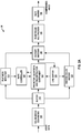
- FIG. 1A is a block diagram that illustrates an example video coding system 10 that may utilize techniques in accordance with aspects described in this disclosure.
- video coder or “coder” refers generically to both video encoders and video decoders.
- video coding or “coding” may refer generically to video encoding and video decoding.
- the aspects described in the present application may be extended to other related devices such as transcoders (e.g., devices that can decode a bitstream and re-encode another bitstream) and middleboxes (e.g., devices that can modify, transform, and/or otherwise manipulate a bitstream).
- transcoders e.g., devices that can decode a bitstream and re-encode another bitstream
- middleboxes e.g., devices that can modify, transform, and/or otherwise manipulate a bitstream.
- video coding system 10 includes a source device 12 that generates encoded video data to be decoded at a later time by a destination device 14.
- the source device 12 and destination device 14 constitute separate devices. It is noted, however, that the source device 12 and destination device 14 may be on or part of the same device, as shown in the example of FIG. 1B .
- the source device 12 and the destination device 14 may respectively comprise any of a wide range of devices, including desktop computers, notebook (e.g., laptop) computers, tablet computers, set-top boxes, telephone handsets such as so-called “smart” phones, so-called “smart” pads, televisions, cameras, display devices, digital media players, video gaming consoles, in-car computers, video streaming devices, devices that are wearable (or removeably attachable) by (to) an entity (e.g., a human, an animal, and/or another controlled device) such as eyewear and/or a wearable computer, devices or apparatus that can be consumed, ingested, or placed within an entity, and/or the like.
- the source device 12 and the destination device 14 may be equipped for wireless communication.
- the destination device 14 may receive, via link 16, the encoded video data to be decoded.
- the link 16 may comprise any type of medium or device capable of moving the encoded video data from the source device 12 to the destination device 14.
- the link 16 may comprise a communication medium to enable the source device 12 to transmit encoded video data to the destination device 14 in real-time.
- the encoded video data may be modulated according to a communication standard, such as a wireless communication protocol, and transmitted to the destination device 14.
- the communication medium may comprise any wireless or wired communication medium, such as a radio frequency (RF) spectrum or one or more physical transmission lines.
- the communication medium may form part of a packet-based network, such as a local area network, a wide-area network, or a global network such as the Internet.
- the communication medium may include routers, switches, base stations, or any other equipment that may be useful to facilitate communication from the source device 12 to the destination device 14.
- the source device 12 includes a video source 18, video encoder 20 and the output interface 22.
- the output interface 22 may include a modulator/demodulator (modem) and/or a transmitter.
- the video source 18 may include a source such as a video capture device, e.g., a video camera, a video archive containing previously captured video, a video feed interface to receive video from a video content provider, and/or a computer graphics system for generating computer graphics data as the source video, or a combination of such sources.
- the video source 18 is a video camera
- the source device 12 and the destination device 14 may form so-called "camera phones" or "video phones", as illustrated in the example of FIG. 1B .
- the techniques described in this disclosure may be applicable to video coding in general, and may be applied to wireless and/or wired applications.
- the captured, pre-captured, or computer-generated video may be encoded by the video encoder 20.
- the encoded video data may be transmitted to the destination device 14 via the output interface 22 of the source device 12.
- the encoded video data may also (or alternatively) be stored onto the storage device 31 for later access by the destination device 14 or other devices, for decoding and/or playback.
- the video encoder 20 illustrated in FIG. 1A and 1B may comprise the video encoder 20 illustrated FIG. 2A or any other video encoder described herein.
- the destination device 14 includes the input interface 28, a video decoder 30, and a display device 32.
- the input interface 28 may include a receiver and/or a modem.
- the input interface 28 of the destination device 14 may receive the encoded video data over the link 16 and/or from the storage device 31.
- the encoded video data communicated over the link 16, or provided on the storage device 31 may include a variety of syntax elements generated by the video encoder 20 for use by a video decoder, such as the video decoder 30, in decoding the video data.
- Such syntax elements may be included with the encoded video data transmitted on a communication medium, stored on a storage medium, or stored a file server.
- the video decoder 30 illustrated in FIG. 1A and 1B may comprise the video decoder 30 illustrated in FIG. 2B or any other video decoder described herein.
- the display device 32 may be integrated with, or external to, the destination device 14.
- the destination device 14 may include an integrated display device and also be configured to interface with an external display device.
- the destination device 14 may be a display device.
- the display device 32 displays the decoded video data to a user, and may comprise any of a variety of display devices such as a liquid crystal display (LCD), a plasma display, an organic light emitting diode (OLED) display, or another type of display device.
- LCD liquid crystal display
- OLED organic light emitting diode
- FIG. 1B shows an example video coding system 10' wherein the source device 12 and the destination device 14 are on or part of a device 11.
- the device 11 may be a telephone handset, such as a "smart" phone or the like.
- the device 11 may include a processor/controller device 13 (optionally present) in operative communication with the source device 12 and the destination device 14.
- the video coding system 10' of FIG. 1B and components thereof, are otherwise similar to the video coding system 10 of FIG. 1A , and components thereof.
- the video encoder 20 and the video decoder 30 may operate according to a video compression standard, such as DSC.
- a video compression standard such as DSC.
- the video encoder 20 and the video decoder 30 may operate according to other proprietary or industry standards, such as the ITU-T H.264 standard, alternatively referred to as MPEG-4, Part 10, AVC, HEVC or extensions of such standards.
- the techniques of this disclosure are not limited to any particular coding standard.
- Other examples of video compression standards include MPEG-2 and ITU-T H.263.
- the video encoder 20 and the video decoder 30 may each be integrated with an audio encoder and decoder, and may include appropriate MUX-DEMUX units, or other hardware and software, to handle encoding of both audio and video in a common data stream or separate data streams. If applicable, in some examples, MUX-DEMUX units may conform to the ITU H.223 multiplexer protocol, or other protocols such as the user datagram protocol (UDP).
- MUX-DEMUX units may conform to the ITU H.223 multiplexer protocol, or other protocols such as the user datagram protocol (UDP).
- the video encoder 20 and the video decoder 30 each may be implemented as any of a variety of suitable encoder circuitry, such as one or more microprocessors, digital signal processors (DSPs), application specific integrated circuits (ASICs), field programmable gate arrays (FPGAs), discrete logic, software, hardware, firmware or any combinations thereof.
- DSPs digital signal processors
- ASICs application specific integrated circuits
- FPGAs field programmable gate arrays
- a device may store instructions for the software in a suitable, non-transitory computer-readable medium and execute the instructions in hardware using one or more processors to perform the techniques of this disclosure.
- Each of the video encoder 20 and the video decoder 30 may be included in one or more encoders or decoders, either of which may be integrated as part of a combined encoder/decoder in a respective device.
- the video encoder 20 encodes video data.
- the video data may comprise one or more pictures. Each of the pictures is a still image forming part of a video. In some instances, a picture may be referred to as a video "frame.”
- the video encoder 20 may generate a bitstream.
- the bitstream may include a sequence of bits that form a coded representation of the video data.
- the bitstream may include coded pictures and associated data.
- a coded picture is a coded representation of a picture.
- the video encoder 20 may perform encoding operations on each picture in the video data.
- the video encoder 20 may generate a series of coded pictures and associated data.
- the associated data may include a set of coding parameters such as a QP.
- the video encoder 20 may partition a picture into equally-sized video blocks.
- a video block may be a two-dimensional array of samples.
- the coding parameters may define a coding option (e.g., a coding mode) for every block of the video data.
- the coding option may be selected in order to achieve a desired rate-distortion performance.
- the video encoder 20 may partition a picture into a plurality of slices.
- Each of the slices may include a spatially distinct region in an image (e.g., a frame) that can be decoded independently without information from the rest of the regions in the image or frame.
- Each image or video frame may be encoded in a single slice or each image or video frame may be encoded in several slices.
- the target bits allocated to encode each slice may be substantially constant.
- the video encoder 20 may perform encoding operations on each slice of the picture.
- the video encoder 20 may generate encoded data associated with the slice.
- the encoded data associated with the slice may be referred to as a "coded slice.”
- FIG. 2A is a block diagram illustrating an example of the video encoder 20 that may implement techniques in accordance with aspects described in this disclosure.
- the video encoder 20 may be configured to perform some or all of the techniques of this disclosure.
- the techniques described in this disclosure may be shared among the various components of the video encoder 20.
- a processor (not shown) may be configured to perform some or all of the techniques described in this disclosure.
- this disclosure describes the video encoder 20 in the context of DSC coding.
- the techniques of this disclosure may be applicable to other coding standards or methods.
- the video encoder 20 includes a plurality of functional components.
- the functional components of the video encoder 20 include a color-space converter 105, a buffer, 110, a flatness detector 115, a rate controller 120, a predictor, quantizer, and reconstructor component 125, a line buffer 130, an indexed color history 135, an entropy encoder 140, a substream multiplexor 145, and a rate buffer 150.
- the video encoder 20 may include more, fewer, or different functional components.
- the color-space converter 105 may convert an input color-space to the color-space used in the coding implementation.
- the color-space of the input video data is in the red, green, and blue (RGB) color-space and the coding is implemented in the luminance Y, chrominance green Cg, and chrominance orange Co (YCoCg) color-space.
- the color-space conversion may be performed by method(s) including shifts and additions to the video data. It is noted that input video data in other color-spaces may be processed and conversions to other color-spaces may also be performed.
- the video encoder 20 may include the buffer 110, the line buffer 130, and/or the rate buffer 150.
- the buffer 110 may hold the color-space converted video data prior to its use by other portions of the video encoder 20.
- the video data may be stored in the RGB color-space and color-space conversion may be performed as needed, since the color-space converted data may require more bits.
- the rate buffer 150 may function as part of the rate control mechanism in the video encoder 20, which will be described in greater detail below in connection with rate controller 120.
- the bits spent on encoding each block can vary highly substantially based on the nature of the block.
- the rate buffer 150 can smooth the rate variations in the compressed video.
- a CBR buffer model is employed in which bits are taken out from the buffer at a constant bit rate. In the CBR buffer model, if the video encoder 20 adds too many bits to the bitstream, the rate buffer 150 may overflow. On the other hand, the video encoder 20 must add enough bits in order to prevent underflow of the rate buffer 150.
- the bits may be added to rate buffer 155 of the video decoder 30 (see FIG. 2B which is described in further detail below) at a constant bit rate, and the video decoder 30 may remove variable numbers of bits for each block.
- the rate buffer 155 of the video decoder 30 should not "underflow” or "overflow” during the decoding of the compressed bit stream.
- the buffer fullness can be defined based on the values BufferCurrentSize representing the number of bits currently in the buffer and BufferMaxSize representing the size of the rate buffer 150, i.e., the maximum number of bits that can be stored in the rate buffer 150 at any point in time.
- the flatness detector 115 can detect changes from complex (i.e., non-flat) areas in the video data to flat (i.e., simple or uniform) areas in the video data, and/or vice versa.
- complex i.e., non-flat
- flat i.e., simple or uniform
- the terms “complex” and “flat” will be used herein to generally refer to the difficulty for the video encoder 20 to encode the respective regions of the video data.
- complex as used herein generally describes a region of the video data as being complex for the video encoder 20 to encode and may, for example, include textured video data, high spatial frequency, and/or other features which are complex to encode.
- the term flat as used herein generally describes a region of the video data as being simple for the video encoder 20 to encoder and may, for example, include a smooth gradient in the video data, low spatial frequency, and/or other features which are simple to encode.
- the transitions from complex to flat regions may be used by the video encoder 20 to reduce quantization artifacts in the encoded video data.
- the rate controller 120 and the predictor, quantizer, and reconstructor component 125 can reduce such quantization artifacts when the transitions from complex to flat regions are identified.
- transitions from flat to complex regions may be used by the video encoder 20 to increase the QP in order to reduce the expected rate required to code a current block.
- the rate controller 120 determines a set of coding parameters, e.g., a QP.
- the QP may be adjusted by the rate controller 120 based on the buffer fullness of the rate buffer 150 and image activity of the video data (e.g., a transition from complex to flat regions or vice versa) in order to maximize picture quality for a target bit rate which ensures that the rate buffer 150 does not overflow or underflow.
- the rate controller 120 also selects a particular coding option (e.g., a particular mode) for each block of the video data in order to achieve the optimal rate-distortion performance.
- the rate controller 120 minimizes the distortion of the reconstructed images such that it satisfies the bit-rate constraint, i.e., the overall actual coding rate fits within the target bit rate.
- the rate controller 120 determines a set of coding parameters, such as QP(s), coding mode(s), etc., to satisfy instantaneous and average constraints on rate while maximizing rate-distortion performance.
- the predictor, quantizer, and reconstructor component 125 may perform at least three encoding operations of the video encoder 20.
- the predictor, quantizer, and reconstructor component 125 may perform prediction in a number of different modes.
- One example predication mode is a modified version of median-adaptive prediction.
- Median-adaptive prediction may be implemented by the lossless JPEG standard (JPEG-LS).
- JPEG-LS lossless JPEG standard
- the modified version of median-adaptive prediction which may be performed by the predictor, quantizer, and reconstructor component 125 may allow for parallel prediction of three consecutive sample values.
- Another example prediction mode is block prediction. In block prediction, samples are predicted from previously reconstructed pixels in the line above or to the left in the same line.
- the video encoder 20 and the video decoder 30 may both perform an identical search on reconstructed pixels to determine the block prediction usages, and thus, no bits need to be sent in the block prediction mode.
- the video encoder 20 may perform the search and signal block prediction vectors in the bitstream, such that the video decoder 30 need not perform a separate search.
- a midpoint prediction mode may also be implemented in which samples are predicted using the midpoint of the component range. The midpoint prediction mode may enable bounding of the number of bits required for the compressed video in even the worst-case sample.
- the predictor, quantizer, and reconstructor component 125 also performs quantization. For example, quantization may be performed via a power-of-2 quantizer which may be implemented using a shifter. It is noted that other quantization techniques may be implemented in lieu of the power-of-2 quantizer. The quantization performed by the predictor, quantizer, and reconstructor component 125 may be based on the QP determined by the rate controller 120. Finally, the predictor, quantizer, and reconstructor component 125 also performs reconstruction which includes adding the inverse quantized residual to the predicted value and ensuring that the result does not fall outside of the valid range of sample values.
- predictor, quantizer, and reconstructor component 125 are merely illustrative and that other approaches may be implemented. It is also noted that the predictor, quantizer, and reconstructor component 125 may include subcomponent(s) for performing the prediction, the quantization, and/or the reconstruction. It is further noted that the prediction, the quantization, and/or the reconstruction may be performed by several separate encoder components in lieu of the predictor, quantizer, and reconstructor component 125.
- the line buffer 130 holds the output from the predictor, quantizer, and reconstructor component 125 so that the predictor, quantizer, and reconstructor component 125 and the indexed color history 135 can use the buffered video data.
- the indexed color history 135 stores recently used pixel values. These recently used pixel values can be referenced directly by the video encoder 20 via a dedicated syntax.
- the entropy encoder 140 encodes the prediction residuals and any other data (e.g., indices identified by the predictor, quantizer, and reconstructor component 125) received from the predictor, quantizer, and reconstructor component 125 based on the indexed color history 135 and the flatness transitions identified by the flatness detector 115.
- the entropy encoder 140 may encode three samples per clock per substream encoder.
- the substream multiplexor 145 may multiplex the bitstream based on a headerless packet multiplexing scheme. This allows the video decoder 30 to run three entropy decoders in parallel, facilitating the decoding of three pixels per clock.
- the substream multiplexor 145 may optimize the packet order so that the packets can be efficiently decoded by the video decoder 30. It is noted that different approaches to entropy coding may be implemented, which may facilitate the decoding of power-of-2 pixels per clock (e.g., 2 pixels/clock or 4pixels/clock).
- FIG. 2B is a block diagram illustrating an example of the video decoder 30 that may implement techniques in accordance with aspects described in this disclosure.
- the video decoder 30 may be configured to perform some or all of the techniques of this disclosure.
- the techniques described in this disclosure may be shared among the various components of the video decoder 30.
- a processor (not shown) may be configured to perform some or all of the techniques described in this disclosure.
- this disclosure describes the video decoder 30 in the context of DSC coding.
- the techniques of this disclosure may be applicable to other coding standards or methods.
- the video decoder 30 includes a plurality of functional components.
- the functional components of the video decoder 30 include a rate buffer 155, a substream demultiplexor 160, an entropy decoder 165, a rate controller 170, a predictor, quantizer, and reconstructor component 175, an indexed color history 180, a line buffer 185, and a color-space converter 190.
- the illustrated components of the video decoder 30 are analogous to the corresponding components described above in connection with the video encoder 20 in FIG. 2A . As such, each of the components of the video decoder 30 may operate in a similar fashion to the corresponding components of the video encoder 20 as described above.
- prevQP is the QP associated with the previous block
- diffBits represents the difference between the previousBlockBits and targetBits
- QpAdj is the QP offset value (e.g., QP adjustment value) that is calculated based on the magnitude of diffBits
- previousBlockBits represents the number of bits used to code the previous block
- targetBits represents a target number
- the current block QP may be derived by adding the offset value QpAdj to the prevQP value.
- the QP value does not decrease in value from the prevQP value when diffBits is positive.
- previousBlockBits ⁇ targetBits diffBits is negative or zero, and currQP does not increase from the prevQP value.
- the offset value QpAdj may be calculated, for example, as a function of diffBits in such a way that QpAdj monotonically increases as the magnitude of diffBits increases.
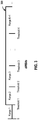
- FIG. 3 provides a graph 300 including an axis on which values of diffBits starting a zero are plotted.
- diffBits may be classified into K+1 ranges using K threshold values. These threshold values are illustrated by the labels Threshold 1, Threshold 2, Threshold 3, ..., and Threshold K and the ranges are illustrated by the labels Range 1, Range 2, Range 3, ..., and Range K+1.
- Threshold 1, Threshold 2, Threshold 3, ..., and Threshold K are illustrated by the labels Range 1, Range 2, Range 3, ..., and Range K+1.
- Each range may be associated with a specific QpAdj value, where the QpAdj value increases as the range index increases.
- the absolute value of diffBits may be classified into J+1 ranges using J threshold values (not illustrated), and there may be a specific QpAdj value assigned for each of the J+1 ranges.
- the currQP value may be adjusted based on the fullness of the buffer (which may be represented in terms of buffer fullness BF), in order to prevent underflow and/or overflow of the buffer.
- a certain threshold e.g., P 1
- currQP may be incremented by a fixed offset value (e.g., p 1 ).
- a plurality of thresholds may be employed, and for each threshold there may be a corresponding offset value to adjust currQP.
- the currQP may be set to a low value (e.g., a value below a defined currQP value), as described in further detail below.
- a fallback mode for a block-based codec having a multitude of prediction/coding modes, each aimed at coding a content type.
- a rate control mechanism may be utilized to select among the prediction modes for each block in an image via considering both the rate and the distortion of each prediction mode.
- a rate-distortion cost may be calculated for each of the prediction modes, and the respective rate-distortion costs may be considered when considering the available prediction modes.
- the rate-control mechanism may be supported by, for example, a hypothetical reference decoder (HRD) buffer model, and it may be a design requirement of the codec that the buffer is never in a state of underflow (e.g., fewer than zero bits in the buffer) or overflow (e.g. buffer size has increased past a set maximum size).
- HRD hypothetical reference decoder
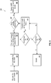
- the method 400 may involve calculating a rate-distortion cost for each prediction mode.
- D mode denotes distortion for a prediction mode.
- D mode may be calculated as a sum of absolute differences (or as a weighted sum of absolute differences) for YCoCg or another color-space. It is noted, however, that other distortion metrics may be used in addition to or in lieu of such metrics based on the sum of absolute differences or the weighted sum of absolute differences.
- R mode denotes bit rate for the prediction mode.
- ⁇ denotes a Lagrangian parameter. The Lagrangian parameter may be a function of bit rate and buffer fullness.
- the method 400 may involve sorting or ranking the prediction modes based on their respective rate-distortion costs. Starting at block 430, the method 400 may involve selecting the prediction mode m with the smallest rate-distortion cost among the available prediction modes (not previously selected) to determine if the selected mode satisfies certain conditions/criteria. In the example of FIG. 4 , the conditions/criteria are Condition A (at block 440) and Condition B (at block 450).
- Condition A at decision block 440 is whether the selection of the prediction mode m ensures that the buffer does not end up in a state of overflow and/or underflow for the fixed-rate codec.
- Condition B at decision block 450 is whether the selection of the prediction mode m results in sufficient remaining bits in the slice to code the remaining blocks of the slice.
- Condition A at decision block 440 is satisfied (i.e.., that the selection of the prediction mode m ensures that the buffer does not end up in a state of overflow and/or underflow for the fixed-rate codec)
- the method 400 may advance to decision block 450 to determine whether Condition B is met (i.e., that the selection of the prediction mode m results in sufficient remaining bits in the slice to code the remaining blocks of the slice). If Condition B is met, then the method 400 may advance to block 460 to break or end.
- Condition A at decision block 440 or Condition B at decision block 450 is not satisfied, then the method 400 may advance to block 470, where the prediction mode m is disabled for the current block, and then advance to decision block 480 ,where the method may determine if there are remaining prediction modes remaining for the current block.
- the method 400 may return to block 430 to select the next prediction mode having the smallest rate-distortion cost among the remaining prediction modes. This selected prediction mode is then tested to determine whether or not this selected prediction mode satisfies Conditions A and B.
- MPP Fallback mode may be abbreviated as MPPF mode.
- each sample in a block may be predicted from a pre-defined midpoint value.
- This midpoint value may be computed in several different ways, as explained in further detail below.
- the midpoint value for the current block can either be fixed, or may depend on neighboring pixel values (e.g., may be calculated based at least in part on the neighboring pixel values).
- calculating the midpoint value may involve calculating the midpoint value based on a mean of pixel values neighboring the current block.
- calculating the midpoint value may involve defaulting to half of a dynamic range of a color-space component of the current block in response to the current block being the first block in the slice.
- the midpoint may be equal to 256.
- the midpoint value may default to 256 if chroma is in range [0, 511] or may default to 0 if chroma is in the range [-256, 255].
- the selection or calculation of the midpoint may be based in part on whether the current block is within the first line of a slice (FLS) or not within the first line in a slice (NFLS). For example, if the current block is within a FLS, but not the first block in the slice, then the previous reconstructed block from the current line may be used to compute the midpoint. In another example, if the current block within a NFLS, then the previous reconstructed line may be used to compute the midpoint.
- FLS first line of a slice
- NFLS slice
- calculating the midpoint value may involve computing the midpoint value based on at least one of a previous reconstructed block and a previous reconstructed line. For example, computing the midpoint value may be based on the previous reconstructed block in response to the current block being within a first line of a slice. In another example, computing the midpoint value may be based on the previous reconstructed line in response to the current block not being within a first line of a slice.
- the midpoint may be calculated based on a dynamic range of a current sample of the current block and/or a step size of a quantizer of the fallback mode.
- DR denotes the dynamic range of the current sample
- stepSize denotes the current step size of the quantizer.
- the value x may be based on either the previous reconstructed block or previous reconstructed line depending on, for example, whether the current block is in a FLS or NFLS.
- x may be calculated as the mean of the previous reconstructed block.
- a simple power-of-2 quantizer may be used, such that the step size determines the number of bitplanes to truncate. This midpoint will be in the following range: MP ⁇ DR 2 , DR 2 + 1 ⁇ stepSize ⁇ 1
- the offset may be omitted. That is, each sample may be predicted from half the dynamic range only.
- a dynamic approach may be utilized in which the encoder decides per-block whether to add an offset to the midpoint prediction or not. Such information may be signaled, for example, by transmitting one bit to the decoder.
- a dynamic approach may be utilized which is implicit rather than explicit. That is, the encoder and decoder can both make a decision whether to add an offset to the midpoint based on data from the previous reconstructed block or the previous reconstructed line.
- the neighbors used for computing the midpoint may be from the previous reconstructed block (same line), rather than the previous reconstructed line.
- the midpoint value may be computed as a mean of the neighboring pixel values, but not clipped by computing the modulus of the current bit depth.
- the current block samples may be predicted from the midpoint value, and the residual may be quantized and signaled to the decoder. It is noted that midpoint value computed for the current block will be identical between encoder and decoder.
- the quantized residuals may be coded using a fixed number of bits per sample. This also has the effect of ensuring a worst-case behavior for MPPF mode.
- the quantized residuals may be grouped and entropy coded, or coded using an alternate variable-length code, such as, for example, Exponential Golomb, Huffman table, etc.
- the current block may be partitioned into a set of sub-blocks.
- a 2x8 block may be partitioned into four 1x4 sub-blocks.
- a separate midpoint value may be calculated for each sub-block.
- Each sample in the current block may be predicted from the midpoint with which it intersects. For example, given a sub-block size of 1x4, the first four pixels in the current block may be predicted from the same midpoint value (e.g., MP 0 ). The next four samples will may be predicted from MP 1 , etc.
- the number of bits per sample for the MPPF mode may be selected based in part on the desired application.
- the total rate for an MPPF block should be strictly less than 96 bits.
- a less than or equal to ( ⁇ ) notation may be used in lieu of the less than ( ⁇ ) notation, such that each MPPF block should be less than or equal to 96 bits.
- the proposed MPPF mode can be tuned to have a worst-case rate per block. This is desirable as the codec can ensure ahead of time that a given number of bits are substantially available for any block within the current slice.
- the only requirement may be that the MPPF mode rate is less than the target compressed bit rate in order to prevent buffer overflow.
- the proposed fallback mode is well-suited for encoding random noise regions, which may have maximum entropy. Since spatial correlation may be zero for such cases, prediction may not provide any rate savings. Therefore, simply predicting from the mean of the random distribution may be optimal. For example, all residuals may be uniformly distributed between [-2 N -1 , 2 N -1 - 1], for a bit depth of N. For noise which is not uniform over [0,2 N - 1], the prediction portion of MPPF mode may further involve reducing the expected rate.
- the video information may include a slice of an image, and the slice may include one or more blocks.
- FIG. 5 is a flowchart illustrating a method 500 for coding video information, according to an embodiment of the present disclosure.
- the steps illustrated in FIG. 5 may be performed by a video encoder (e.g., the video encoder 20 in FIG. 2A ), a video decoder (e.g., the video decoder 30 in FIG. 2B ), or component(s) thereof, such as for example, the rate controller 120, the predictor, quantizer, and reconstructor component 125, the entropy encoder 140, and the rate buffer 150.
- a video coder also simply referred to as coder
- coder may be the video encoder 20, the video decoder 30, or another component.
- the coder or component(s) thereof may be implemented on device that includes an integrated global memory shared by a plurality of programmable compute units that includes a buffer, wherein the buffer may include a first-in-first-out (FIFO) buffer.
- the device may further include an integrated circuit (IC) comprising that includes a graphics processing unit (GPU), wherein the GPU may include one or more programmable compute units.
- IC integrated circuit
- GPU graphics processing unit
- the method 500 begins at block 510.
- the coder identifies one or more prediction modes for a fixed rate codec, each prediction mode having a rate-distortion cost.
- the one or more prediction modes may include, for example, one or more of a DCT mode, a block prediction mode, and a pattern prediction mode.
- the coder selects, for a current block, a prediction mode that has the lowest rate-distortion cost from among the one more prediction modes not previously selected.
- the coder determines whether the selected prediction mode would result in overflow or underflow of a buffer of the fixed rate codec.
- the coder determines whether the selected prediction mode would result in remaining bits in the slice being insufficient to code remaining blocks of the slice.
- the coder in response to each of the selected one or more prediction modes resulting in at least one of (i) overflow or underflow of the buffer and (ii) insufficient remaining bits in the slice to code the remaining blocks of the slice, the coder utilizes a fallback mode to code the current block.
- the fallback mode may involve determining a midpoint value of the current block and predicting current block samples from the midpoint value.
- block 550 may involve the coder determining the midpoint value by defaulting to half of a dynamic range of a color-space component of the current block in response to the current block being the first block in the slice. In another example, block 550 may involve the coder determining the midpoint value based on a mean of pixel values neighboring the current block.
- block 550 may involve the coder determining the midpoint value based on at least one of a previous reconstructed block and a previous reconstructed line. For example, the coder may calculate or compute the midpoint value based on the previous reconstructed block in response to the current block being within a first line of a slice. In another example, the coder may calculate or compute the midpoint value based on the previous reconstructed line in response to the current block not being within a first line of a slice.
- the coder may determine the midpoint based on a dynamic range of a current sample of the current block and a step size of a quantizer of the fallback mode.
- Information and signals disclosed herein may be represented using any of a variety of different technologies and techniques.
- data, instructions, commands, information, signals, bits, symbols, and chips that may be referenced throughout the above description may be represented by voltages, currents, electromagnetic waves, magnetic fields or particles, optical fields or particles, or any combination thereof.
- the techniques described herein may be implemented in hardware, software, firmware, or any combination thereof. Such techniques may be implemented in any of a variety of devices such as general purposes computers, wireless communication device handsets, or integrated circuit devices having multiple uses including applications in wireless communication device handsets, automotive, appliances, wearables, and/or other devices. Any features described as devices or components may be implemented together in an integrated logic device or separately as discrete but interoperable logic devices. If implemented in software, the techniques may be realized at least in part by a computer-readable data storage medium comprising program code including instructions that, when executed, performs one or more of the methods described above.
- the computer-readable data storage medium may form part of a computer program product, which may include packaging materials.
- the computer-readable medium may comprise memory or data storage media, such as random access memory (RAM) such as synchronous dynamic random access memory (SDRAM), read-only memory (ROM), non-volatile random access memory (NVRAM), electrically erasable programmable read-only memory (EEPROM), FLASH memory, magnetic or optical data storage media, and the like.
- RAM random access memory
- SDRAM synchronous dynamic random access memory
- ROM read-only memory
- NVRAM non-volatile random access memory
- EEPROM electrically erasable programmable read-only memory
- FLASH memory magnetic or optical data storage media, and the like.
- the techniques additionally, or alternatively, may be realized at least in part by a computer-readable communication medium that carries or communicates program code in the form of instructions or data structures and that can be accessed, read, and/or executed by a computer, such as propagated signals or waves.
- the program code may be executed by a processor, which may include one or more processors, such as one or more digital signal processors (DSPs), general purpose microprocessors, an application specific integrated circuits (ASICs), field programmable logic arrays (FPGAs), or other equivalent integrated or discrete logic circuitry.
- DSPs digital signal processors
- ASICs application specific integrated circuits
- FPGAs field programmable logic arrays
- a general purpose processor may be a microprocessor; but in the alternative, the processor may be any conventional processor, controller, microcontroller, or state machine.
- a processor may also be implemented as a combination of computing devices, e.g., a combination of a DSP and a microprocessor, a plurality of microprocessors, one or more microprocessors in conjunction with a DSP core, or any other such configuration.
- processor may refer to any of the foregoing structure, any combination of the foregoing structure, or any other structure or apparatus suitable for implementation of the techniques described herein.
- functionality described herein may be provided within dedicated software or hardware configured for encoding and decoding, or incorporated in a combined video encoder-decoder (CODEC).
- CODEC combined video encoder-decoder
- the techniques could be fully implemented in one or more circuits or logic elements.
- the techniques of this disclosure may be implemented in a wide variety of devices or apparatuses, including a wireless handset, an IC or a set of ICs (e.g., a chip set).
- Various components, or units are described in this disclosure to emphasize functional aspects of devices configured to perform the disclosed techniques, but do not necessarily require realization by different hardware units. Rather, as described above, various units may be combined in a codec hardware unit or provided by a collection of inter-operative hardware units, including one or more processors as described above, in conjunction with suitable software and/or firmware.
Description
- This disclosure relates to the field of video coding and compression, and particularly, to video compression for transmission over display links, such as display stream compression (DSC).
- Digital video capabilities can be incorporated into a wide range of displays, including digital televisions, personal digital assistants (PDAs), laptop computers, desktop monitors, digital cameras, digital recording devices, digital media players, video gaming devices, video game consoles, cellular or satellite radio telephones, video teleconferencing devices, and the like. Display links are used to connect displays to appropriate source devices. The bandwidth requirements of display links are proportional to the resolution of the displays, and thus, high-resolution displays require large bandwidth display links. Some display links do not have the bandwidth to support high resolution displays. Video compression can be used to reduce the bandwidth requirements such that lower bandwidth display links can be used to provide digital video to high resolution displays.
- Others have tried to utilize image compression on the pixel data. However, such schemes are sometimes not visually lossless or can be difficult and expensive to implement in conventional display devices.
- The Video Electronics Standards Association (VESA) has developed display stream compression (DSC) as a standard for display link video compression. The display link video compression technique, such as DSC, should provide, among other things, picture quality that is visually lossless (i.e., pictures having a level of quality such that users cannot tell the compression is active). The display link video compression technique should also provide a scheme that is easy and inexpensive to implement in real-time with conventional hardware.
- Display Stream Compression (DSC) Standard v1.1, VESA STANDARD, VESA, US vol. V1.1 1 August 2014 (2014-08-01), pages 1-125, XP008177954 describes the Vesa display stream compression standard. This document describes how DSC specifies the algorithms used for compressing and decompressing image display streams, including the specification of the syntax and semantics of the compressed video bitstream. It also describes how DSC is designed for real-time systems, with real-time compression, transmission, decompression, and display. It also describes how systems that use DSC must follow a suitable transport specification in which the Transport Layer conveys DSC streams, from source to destination. Finally it describes how DSC is a compression and decompression standard for display streams between two distinct devices, either from one box level product to another, or from one chip to another within a box-level product, by way of a display stream interface.
- The invention is defined in the appended claims to which reference should now be made. The systems, methods and devices of this disclosure each have several innovative aspects, no single one of which is solely responsible for the desirable attributes disclosed herein.
- In one aspect, there is provided a method for coding video information relating to a slice of an image, wherein the slice includes one or more blocks. The method may involve identifying one or more prediction modes for a fixed-rate codec, wherein each prediction mode has associated with it a rate-distortion cost. The method may involve selecting, for a current block, a prediction mode that has the lowest rate-distortion cost from among the one more prediction modes not previously selected. The method may involve determining whether the selected prediction mode would result in overflow or underflow of a buffer of the fixed-rate codec. The method may involve determining whether the selected prediction mode would result in remaining bits in the slice being insufficient to code remaining blocks of the slice. The method may involve utilizing a fallback mode to code the current block in response to each of the selected one or more prediction modes resulting in at least one of (i) overflow or underflow of the buffer and (ii) insufficient remaining bits in the slice to code the remaining blocks of the slice. In related aspects, the fallback mode may involve determining a midpoint value of the current block and predicting current block samples from the midpoint value.
- In another aspect, there is provided a device that may include a memory configured to store video information relating to a slice of an image, wherein the slice includes one or more blocks. The device may include at least one processor circuit coupled to the memory and configured to: identify one or more prediction modes for a fixed-rate codec, each prediction mode having a rate-distortion cost; select, for a current block, a prediction mode that has the lowest rate-distortion cost from among the one more prediction modes not previously selected; determine whether the selected prediction mode would result in overflow or underflow of a buffer of the fixed-rate codec; determine whether the selected prediction mode would result in remaining bits in the slice being insufficient to code remaining blocks of the slice; and utilize a fallback mode to code the current block in response to each of the selected one or more prediction modes resulting in at least one of (i) overflow or underflow of the buffer and (ii) insufficient remaining bits in the slice to code the remaining blocks of the slice, wherein the fallback mode may include determining a midpoint value of the current block and predicting current block samples from the midpoint value.
-
-
FIG. 1A is a block diagram illustrating an example video encoding and decoding system that may utilize techniques in accordance with aspects described in this disclosure. -
FIG. 1B is a block diagram illustrating another example video encoding and decoding system that may perform techniques in accordance with aspects described in this disclosure. -
FIG. 2A is a block diagram illustrating an example of a video encoder that may implement techniques in accordance with aspects described in this disclosure. -
FIG. 2B is a block diagram illustrating an example of a video decoder that may implement techniques in accordance with aspects described in this disclosure. -
FIG. 3 shows an example approach to determining quantization parameter (QP) adjustment value(s). -
FIG. 4 is a flowchart illustrating an example method for coding a current block of a slice based on rate-distortion criteria for a fixed-rate codec, in accordance with aspects described in this disclosure. -
FIG. 5 is a flowchart illustrating an example method for coding video information, in accordance with aspects described in this disclosure. - In general, the present disclosure relates to techniques of improving video compression techniques such as display stream compression (DSC). More specifically, this disclosure relates to systems and methods for detecting a transition from a flat or smooth region to a complex region of an image to be coded. Described herein are techniques for complex region detection in video data in the context of video compression techniques, such as, for example, DSC. Aspects of this disclosure relate to ensuring that underflow or overflow of the rate buffer during coding is avoided.
- While certain embodiments are described herein in the context of the DSC standard, one having ordinary skill in the art would appreciate that systems and methods disclosed herein may be applicable to any suitable video coding standard. For example, embodiments disclosed herein may be applicable to one or more of the following standards: International Telecommunication Union (ITU) Telecommunication Standardization Sector (ITU-T) H.261, International Organization for Standardization/International Electrotechnical Commission (ISO/IEC) Moving Picture Experts Group-1 (MPEG-1) Visual, ITU-T H.262 or ISO/IEC MPEG-2 Visual, ITU-T H.263, ISO/IEC MPEG-4 Visual, ITU-T H.264 (also known as ISO/IEC MPEG-4 AVC), High Efficiency Video Coding (HEVC), and any extensions to such standards. The techniques described herein may be particularly applicable to standards which incorporate a constant bit rate (CBR) buffer model. Also, the techniques described in this disclosure may become part of standards developed in the future. In other words, the techniques described in this disclosure may be applicable to previously developed video coding standards, video coding standards currently under development, and forthcoming video coding standards.
- The concepts of this disclosure may be integrated in or a be part of a codec (e.g., DSC) that includes several elements and/or modes aimed at encoding/decoding various types of content with substantially visually lossless performance. This disclosure provides a complex region detection algorithm that detects the transition from a smooth/flat region (e.g., a region that is easy to code) to a complex region (e.g., a region that is relatively difficult to code or requires a higher number of bits to code). When such a transition is detected, the quantization parameter (QP) used in the codec is increased to a high value in order to reduce the expected rate required to code the current block. This is desirable as the complexity of visual information in the complex region may mask artifacts more so than would occur for a smooth/flat region. In addition, the low rate is desirable to prevent the coder from spending too many bits on a complex block (e.g., well in excess of the target bit rate).
- A digital image, such as a video image, a TV image, a still image or an image generated by a video recorder or a computer, may include pixels or samples arranged in horizontal and vertical lines. The number of pixels in a single image is typically in the tens of thousands. Each pixel typically contains luminance and chrominance information. Without compression, the sheer quantity of information to be conveyed from an image encoder to an image decoder would render real-time image transmission impractical. To reduce the amount of information to be transmitted, a number of different compression methods, such as JPEG, MPEG and H.263 standards, have been developed.
- Video coding standards include ITU-T H.261, ISO/IEC MPEG-1 Visual, ITU-T H.262 or ISO/IEC MPEG-2 Visual, ITU-T H.263, ISO/IEC MPEG-4 Visual, ITU-T H.264 (also known as ISO/IEC MPEG-4 AVC), and HEVC including extensions of such standards.
- In addition, a video coding standard, namely DSC, has been developed by VESA. The DSC standard is a video compression standard which can compress video for transmission over display links. As the resolution of displays increases, the bandwidth of the video data required to drive the displays increases correspondingly. Some display links may not have the bandwidth to transmit all of the video data to the display for such resolutions. Accordingly, the DSC standard specifies a compression standard for interoperable, visually lossless compression over display links.
- The DSC standard is different from other video coding standards, such as H.264 and HEVC. DSC includes intra-frame compression, but does not include inter-frame compression, meaning that temporal information may not be used by the DSC standard in coding the video data. In contrast, other video coding standards may employ inter-frame compression in their video coding techniques.
- Various aspects of the novel systems, apparatuses, and methods are described more fully hereinafter with reference to the accompanying drawings. This disclosure may, however, be embodied in many different forms and should not be construed as limited to any specific structure or function presented throughout this disclosure. Rather, these aspects are provided so that this disclosure will be thorough and complete, and will fully convey the scope of the disclosure to those skilled in the art. Based on the teachings herein one skilled in the art should appreciate that the scope of the disclosure is intended to cover any aspect of the novel systems, apparatuses, and methods disclosed herein, whether implemented independently of, or combined with, any other aspect of the present disclosure. For example, an apparatus may be implemented or a method may be practiced using any number of the aspects set forth herein. In addition, the scope of the present disclosure is intended to cover such an apparatus or method which is practiced using other structure, functionality, or structure and functionality in addition to or other than the various aspects of the present disclosure set forth herein. It should be understood that any aspect disclosed herein may be embodied by one or more elements of a claim.
- Although particular aspects are described herein, many variations and permutations of these aspects fall within the scope of the disclosure. Although some benefits and advantages of the preferred aspects are mentioned, the scope of the disclosure is not intended to be limited to particular benefits, uses, or objectives. Rather, aspects of the disclosure are intended to be broadly applicable to different wireless technologies, system configurations, networks, and transmission protocols, some of which are illustrated by way of example in the figures and in the following description of the preferred aspects. The detailed description and drawings are merely illustrative of the disclosure rather than limiting, the scope of the disclosure being defined by the appended claims and equivalents thereof.
- The attached drawings illustrate examples. Elements indicated by reference numbers in the attached drawings correspond to elements indicated by like reference numbers in the following description. In this disclosure, elements having names that start with ordinal words (e.g., "first," "second," "third," and so on) do not necessarily imply that the elements have a particular order. Rather, such ordinal words are merely used to refer to different elements of a same or similar type.
-
FIG. 1A is a block diagram that illustrates an examplevideo coding system 10 that may utilize techniques in accordance with aspects described in this disclosure. As used described herein, the term "video coder" or "coder" refers generically to both video encoders and video decoders. In this disclosure, the terms "video coding" or "coding" may refer generically to video encoding and video decoding. In addition to video encoders and video decoders, the aspects described in the present application may be extended to other related devices such as transcoders (e.g., devices that can decode a bitstream and re-encode another bitstream) and middleboxes (e.g., devices that can modify, transform, and/or otherwise manipulate a bitstream). - As shown in
FIG. 1A ,video coding system 10 includes asource device 12 that generates encoded video data to be decoded at a later time by adestination device 14. In the example ofFIG. 1A , thesource device 12 anddestination device 14 constitute separate devices. It is noted, however, that thesource device 12 anddestination device 14 may be on or part of the same device, as shown in the example ofFIG. 1B . - With reference once again, to
FIG. 1A , thesource device 12 and thedestination device 14 may respectively comprise any of a wide range of devices, including desktop computers, notebook (e.g., laptop) computers, tablet computers, set-top boxes, telephone handsets such as so-called "smart" phones, so-called "smart" pads, televisions, cameras, display devices, digital media players, video gaming consoles, in-car computers, video streaming devices, devices that are wearable (or removeably attachable) by (to) an entity (e.g., a human, an animal, and/or another controlled device) such as eyewear and/or a wearable computer, devices or apparatus that can be consumed, ingested, or placed within an entity, and/or the like. In various embodiments, thesource device 12 and thedestination device 14 may be equipped for wireless communication. - The
destination device 14 may receive, vialink 16, the encoded video data to be decoded. Thelink 16 may comprise any type of medium or device capable of moving the encoded video data from thesource device 12 to thedestination device 14. In the example ofFIG. 1A , thelink 16 may comprise a communication medium to enable thesource device 12 to transmit encoded video data to thedestination device 14 in real-time. The encoded video data may be modulated according to a communication standard, such as a wireless communication protocol, and transmitted to thedestination device 14. The communication medium may comprise any wireless or wired communication medium, such as a radio frequency (RF) spectrum or one or more physical transmission lines. The communication medium may form part of a packet-based network, such as a local area network, a wide-area network, or a global network such as the Internet. The communication medium may include routers, switches, base stations, or any other equipment that may be useful to facilitate communication from thesource device 12 to thedestination device 14. - In the example of
FIG. 1A , thesource device 12 includes avideo source 18,video encoder 20 and theoutput interface 22. In some cases, theoutput interface 22 may include a modulator/demodulator (modem) and/or a transmitter. In thesource device 12, thevideo source 18 may include a source such as a video capture device, e.g., a video camera, a video archive containing previously captured video, a video feed interface to receive video from a video content provider, and/or a computer graphics system for generating computer graphics data as the source video, or a combination of such sources. As one example, if thevideo source 18 is a video camera, thesource device 12 and thedestination device 14 may form so-called "camera phones" or "video phones", as illustrated in the example ofFIG. 1B . However, the techniques described in this disclosure may be applicable to video coding in general, and may be applied to wireless and/or wired applications. - The captured, pre-captured, or computer-generated video may be encoded by the
video encoder 20. The encoded video data may be transmitted to thedestination device 14 via theoutput interface 22 of thesource device 12. The encoded video data may also (or alternatively) be stored onto the storage device 31 for later access by thedestination device 14 or other devices, for decoding and/or playback. Thevideo encoder 20 illustrated inFIG. 1A and1B may comprise thevideo encoder 20 illustratedFIG. 2A or any other video encoder described herein. - In the example of
FIG. 1A , thedestination device 14 includes theinput interface 28, avideo decoder 30, and adisplay device 32. In some cases, theinput interface 28 may include a receiver and/or a modem. Theinput interface 28 of thedestination device 14 may receive the encoded video data over thelink 16 and/or from the storage device 31. The encoded video data communicated over thelink 16, or provided on the storage device 31, may include a variety of syntax elements generated by thevideo encoder 20 for use by a video decoder, such as thevideo decoder 30, in decoding the video data. Such syntax elements may be included with the encoded video data transmitted on a communication medium, stored on a storage medium, or stored a file server. Thevideo decoder 30 illustrated inFIG. 1A and1B may comprise thevideo decoder 30 illustrated inFIG. 2B or any other video decoder described herein. - The
display device 32 may be integrated with, or external to, thedestination device 14. In some examples, thedestination device 14 may include an integrated display device and also be configured to interface with an external display device. In other examples, thedestination device 14 may be a display device. In general, thedisplay device 32 displays the decoded video data to a user, and may comprise any of a variety of display devices such as a liquid crystal display (LCD), a plasma display, an organic light emitting diode (OLED) display, or another type of display device. - In related aspects,
FIG. 1B shows an example video coding system 10' wherein thesource device 12 and thedestination device 14 are on or part of adevice 11. Thedevice 11 may be a telephone handset, such as a "smart" phone or the like. Thedevice 11 may include a processor/controller device 13 (optionally present) in operative communication with thesource device 12 and thedestination device 14. The video coding system 10' ofFIG. 1B , and components thereof, are otherwise similar to thevideo coding system 10 ofFIG. 1A , and components thereof. - The
video encoder 20 and thevideo decoder 30 may operate according to a video compression standard, such as DSC. Alternatively, thevideo encoder 20 and thevideo decoder 30 may operate according to other proprietary or industry standards, such as the ITU-T H.264 standard, alternatively referred to as MPEG-4,Part 10, AVC, HEVC or extensions of such standards. The techniques of this disclosure, however, are not limited to any particular coding standard. Other examples of video compression standards include MPEG-2 and ITU-T H.263. - Although not shown in the examples of
FIGs. 1A and1B , thevideo encoder 20 and thevideo decoder 30 may each be integrated with an audio encoder and decoder, and may include appropriate MUX-DEMUX units, or other hardware and software, to handle encoding of both audio and video in a common data stream or separate data streams. If applicable, in some examples, MUX-DEMUX units may conform to the ITU H.223 multiplexer protocol, or other protocols such as the user datagram protocol (UDP). - The
video encoder 20 and thevideo decoder 30 each may be implemented as any of a variety of suitable encoder circuitry, such as one or more microprocessors, digital signal processors (DSPs), application specific integrated circuits (ASICs), field programmable gate arrays (FPGAs), discrete logic, software, hardware, firmware or any combinations thereof. When the techniques are implemented partially in software, a device may store instructions for the software in a suitable, non-transitory computer-readable medium and execute the instructions in hardware using one or more processors to perform the techniques of this disclosure. Each of thevideo encoder 20 and thevideo decoder 30 may be included in one or more encoders or decoders, either of which may be integrated as part of a combined encoder/decoder in a respective device. - As mentioned briefly above, the
video encoder 20 encodes video data. The video data may comprise one or more pictures. Each of the pictures is a still image forming part of a video. In some instances, a picture may be referred to as a video "frame." When thevideo encoder 20 encodes the video data, thevideo encoder 20 may generate a bitstream. The bitstream may include a sequence of bits that form a coded representation of the video data. The bitstream may include coded pictures and associated data. A coded picture is a coded representation of a picture. - To generate the bitstream, the
video encoder 20 may perform encoding operations on each picture in the video data. When thevideo encoder 20 performs encoding operations on the pictures, thevideo encoder 20 may generate a series of coded pictures and associated data. The associated data may include a set of coding parameters such as a QP. To generate a coded picture, thevideo encoder 20 may partition a picture into equally-sized video blocks. A video block may be a two-dimensional array of samples. The coding parameters may define a coding option (e.g., a coding mode) for every block of the video data. The coding option may be selected in order to achieve a desired rate-distortion performance. - In some examples, the
video encoder 20 may partition a picture into a plurality of slices. Each of the slices may include a spatially distinct region in an image (e.g., a frame) that can be decoded independently without information from the rest of the regions in the image or frame. Each image or video frame may be encoded in a single slice or each image or video frame may be encoded in several slices. In DSC, the target bits allocated to encode each slice may be substantially constant. As part of performing an encoding operation on a picture, thevideo encoder 20 may perform encoding operations on each slice of the picture. When thevideo encoder 20 performs an encoding operation on a slice, thevideo encoder 20 may generate encoded data associated with the slice. The encoded data associated with the slice may be referred to as a "coded slice." -
FIG. 2A is a block diagram illustrating an example of thevideo encoder 20 that may implement techniques in accordance with aspects described in this disclosure. Thevideo encoder 20 may be configured to perform some or all of the techniques of this disclosure. In some examples, the techniques described in this disclosure may be shared among the various components of thevideo encoder 20. In some examples, additionally or alternatively, a processor (not shown) may be configured to perform some or all of the techniques described in this disclosure. - For purposes of explanation, this disclosure describes the
video encoder 20 in the context of DSC coding. However, the techniques of this disclosure may be applicable to other coding standards or methods. - In the example of
FIG. 2A , thevideo encoder 20 includes a plurality of functional components. The functional components of thevideo encoder 20 include a color-space converter 105, a buffer, 110, a flatness detector 115, arate controller 120, a predictor, quantizer, andreconstructor component 125, aline buffer 130, an indexedcolor history 135, anentropy encoder 140, asubstream multiplexor 145, and arate buffer 150. In other examples, thevideo encoder 20 may include more, fewer, or different functional components. - The color-
space converter 105 may convert an input color-space to the color-space used in the coding implementation. For example, in one exemplary embodiment, the color-space of the input video data is in the red, green, and blue (RGB) color-space and the coding is implemented in the luminance Y, chrominance green Cg, and chrominance orange Co (YCoCg) color-space. The color-space conversion may be performed by method(s) including shifts and additions to the video data. It is noted that input video data in other color-spaces may be processed and conversions to other color-spaces may also be performed. - In related aspects, the
video encoder 20 may include thebuffer 110, theline buffer 130, and/or therate buffer 150. For example, thebuffer 110 may hold the color-space converted video data prior to its use by other portions of thevideo encoder 20. In another example, the video data may be stored in the RGB color-space and color-space conversion may be performed as needed, since the color-space converted data may require more bits. - The
rate buffer 150 may function as part of the rate control mechanism in thevideo encoder 20, which will be described in greater detail below in connection withrate controller 120. The bits spent on encoding each block can vary highly substantially based on the nature of the block. Therate buffer 150 can smooth the rate variations in the compressed video. In some embodiments, a CBR buffer model is employed in which bits are taken out from the buffer at a constant bit rate. In the CBR buffer model, if thevideo encoder 20 adds too many bits to the bitstream, therate buffer 150 may overflow. On the other hand, thevideo encoder 20 must add enough bits in order to prevent underflow of therate buffer 150. - On the video decoder side, the bits may be added to rate buffer 155 of the video decoder 30 (see
FIG. 2B which is described in further detail below) at a constant bit rate, and thevideo decoder 30 may remove variable numbers of bits for each block. To ensure proper decoding, therate buffer 155 of thevideo decoder 30 should not "underflow" or "overflow" during the decoding of the compressed bit stream. - In some embodiments, the buffer fullness (BF) can be defined based on the values BufferCurrentSize representing the number of bits currently in the buffer and BufferMaxSize representing the size of the
rate buffer 150, i.e., the maximum number of bits that can be stored in therate buffer 150 at any point in time. The BF may be calculated as:
- It is noted that the above approach to calculating BF is merely exemplary, and that the BF may be calculated in any number of different ways, depending on the particular implementation or context.
- The flatness detector 115 can detect changes from complex (i.e., non-flat) areas in the video data to flat (i.e., simple or uniform) areas in the video data, and/or vice versa. The terms "complex" and "flat" will be used herein to generally refer to the difficulty for the
video encoder 20 to encode the respective regions of the video data. Thus, the term complex as used herein generally describes a region of the video data as being complex for thevideo encoder 20 to encode and may, for example, include textured video data, high spatial frequency, and/or other features which are complex to encode. The term flat as used herein generally describes a region of the video data as being simple for thevideo encoder 20 to encoder and may, for example, include a smooth gradient in the video data, low spatial frequency, and/or other features which are simple to encode. The transitions from complex to flat regions may be used by thevideo encoder 20 to reduce quantization artifacts in the encoded video data. Specifically, therate controller 120 and the predictor, quantizer, andreconstructor component 125 can reduce such quantization artifacts when the transitions from complex to flat regions are identified. Similarly, transitions from flat to complex regions may be used by thevideo encoder 20 to increase the QP in order to reduce the expected rate required to code a current block. - The
rate controller 120 determines a set of coding parameters, e.g., a QP. The QP may be adjusted by therate controller 120 based on the buffer fullness of therate buffer 150 and image activity of the video data (e.g., a transition from complex to flat regions or vice versa) in order to maximize picture quality for a target bit rate which ensures that therate buffer 150 does not overflow or underflow. Therate controller 120 also selects a particular coding option (e.g., a particular mode) for each block of the video data in order to achieve the optimal rate-distortion performance. Therate controller 120 minimizes the distortion of the reconstructed images such that it satisfies the bit-rate constraint, i.e., the overall actual coding rate fits within the target bit rate. Thus, one purpose of therate controller 120 is to determine a set of coding parameters, such as QP(s), coding mode(s), etc., to satisfy instantaneous and average constraints on rate while maximizing rate-distortion performance. - The predictor, quantizer, and
reconstructor component 125 may perform at least three encoding operations of thevideo encoder 20. The predictor, quantizer, andreconstructor component 125 may perform prediction in a number of different modes. One example predication mode is a modified version of median-adaptive prediction. Median-adaptive prediction may be implemented by the lossless JPEG standard (JPEG-LS). The modified version of median-adaptive prediction which may be performed by the predictor, quantizer, andreconstructor component 125 may allow for parallel prediction of three consecutive sample values. Another example prediction mode is block prediction. In block prediction, samples are predicted from previously reconstructed pixels in the line above or to the left in the same line. In some embodiments, thevideo encoder 20 and thevideo decoder 30 may both perform an identical search on reconstructed pixels to determine the block prediction usages, and thus, no bits need to be sent in the block prediction mode. In other embodiments, thevideo encoder 20 may perform the search and signal block prediction vectors in the bitstream, such that thevideo decoder 30 need not perform a separate search. A midpoint prediction mode may also be implemented in which samples are predicted using the midpoint of the component range. The midpoint prediction mode may enable bounding of the number of bits required for the compressed video in even the worst-case sample. - The predictor, quantizer, and
reconstructor component 125 also performs quantization. For example, quantization may be performed via a power-of-2 quantizer which may be implemented using a shifter. It is noted that other quantization techniques may be implemented in lieu of the power-of-2 quantizer. The quantization performed by the predictor, quantizer, andreconstructor component 125 may be based on the QP determined by therate controller 120. Finally, the predictor, quantizer, andreconstructor component 125 also performs reconstruction which includes adding the inverse quantized residual to the predicted value and ensuring that the result does not fall outside of the valid range of sample values. - It is noted that the above-described example approaches to prediction, quantization, and reconstruction performed by the predictor, quantizer, and
reconstructor component 125 are merely illustrative and that other approaches may be implemented. It is also noted that the predictor, quantizer, andreconstructor component 125 may include subcomponent(s) for performing the prediction, the quantization, and/or the reconstruction. It is further noted that the prediction, the quantization, and/or the reconstruction may be performed by several separate encoder components in lieu of the predictor, quantizer, andreconstructor component 125. - The
line buffer 130 holds the output from the predictor, quantizer, andreconstructor component 125 so that the predictor, quantizer, andreconstructor component 125 and the indexedcolor history 135 can use the buffered video data. The indexedcolor history 135 stores recently used pixel values. These recently used pixel values can be referenced directly by thevideo encoder 20 via a dedicated syntax. - The
entropy encoder 140 encodes the prediction residuals and any other data (e.g., indices identified by the predictor, quantizer, and reconstructor component 125) received from the predictor, quantizer, andreconstructor component 125 based on the indexedcolor history 135 and the flatness transitions identified by the flatness detector 115. In some examples, theentropy encoder 140 may encode three samples per clock per substream encoder. Thesubstream multiplexor 145 may multiplex the bitstream based on a headerless packet multiplexing scheme. This allows thevideo decoder 30 to run three entropy decoders in parallel, facilitating the decoding of three pixels per clock. Thesubstream multiplexor 145 may optimize the packet order so that the packets can be efficiently decoded by thevideo decoder 30. It is noted that different approaches to entropy coding may be implemented, which may facilitate the decoding of power-of-2 pixels per clock (e.g., 2 pixels/clock or 4pixels/clock). -
FIG. 2B is a block diagram illustrating an example of thevideo decoder 30 that may implement techniques in accordance with aspects described in this disclosure. Thevideo decoder 30 may be configured to perform some or all of the techniques of this disclosure. In some examples, the techniques described in this disclosure may be shared among the various components of thevideo decoder 30. In some examples, additionally or alternatively, a processor (not shown) may be configured to perform some or all of the techniques described in this disclosure. - For purposes of explanation, this disclosure describes the
video decoder 30 in the context of DSC coding. However, the techniques of this disclosure may be applicable to other coding standards or methods. - In the example of
FIG. 2B , thevideo decoder 30 includes a plurality of functional components. The functional components of thevideo decoder 30 include arate buffer 155, asubstream demultiplexor 160, anentropy decoder 165, arate controller 170, a predictor, quantizer, andreconstructor component 175, an indexedcolor history 180, aline buffer 185, and a color-space converter 190. The illustrated components of thevideo decoder 30 are analogous to the corresponding components described above in connection with thevideo encoder 20 inFIG. 2A . As such, each of the components of thevideo decoder 30 may operate in a similar fashion to the corresponding components of thevideo encoder 20 as described above. - In one approach, the QP for the current block (denoted as currQP) may be derived or calculated based on the following equation:

where prevQP is the QP associated with the previous block, diffBits represents the difference between the previousBlockBits and targetBits, QpAdj is the QP offset value (e.g., QP adjustment value) that is calculated based on the magnitude of diffBits, previousBlockBits represents the number of bits used to code the previous block, and targetBits represents a target number of bits in which to code the current block. When previousBlockBits > targetBits, diffBits is positive, and the current block QP may be derived by adding the offset value QpAdj to the prevQP value. In other words, the QP value does not decrease in value from the prevQP value when diffBits is positive. When previousBlockBits ≤ targetBits, diffBits is negative or zero, and currQP does not increase from the prevQP value. It is noted that the offset value QpAdj may be calculated, for example, as a function of diffBits in such a way that QpAdj monotonically increases as the magnitude of diffBits increases. - One technique, referred to herein as a default technique, for calculating the QP adjustment value QpAdj will now be described with reference to
FIG. 3. FIG. 3 provides agraph 300 including an axis on which values of diffBits starting a zero are plotted. In the default technique, when diffBits > 0, diffBits may be classified into K+1 ranges using K threshold values. These threshold values are illustrated by thelabels Threshold 1,Threshold 2,Threshold 3, ..., and Threshold K and the ranges are illustrated by thelabels Range 1,Range 2,Range 3, ..., and Range K+1. In the default technique ofFIG. 3 , there is shown one approach to segmenting diffBits into K+1 ranges using K threshold values. Each range may be associated with a specific QpAdj value, where the QpAdj value increases as the range index increases. When diffBits ≤ 0, the absolute value of diffBits may be classified into J+1 ranges using J threshold values (not illustrated), and there may be a specific QpAdj value assigned for each of the J+1 ranges. - In other aspects, the currQP value may be adjusted based on the fullness of the buffer (which may be represented in terms of buffer fullness BF), in order to prevent underflow and/or overflow of the buffer. In particular, when BF exceeds a certain threshold (e.g., P1), currQP may be incremented by a fixed offset value (e.g., p1). For example, currQP may be adjusted as follows: currQP += p1. Further, when BF falls below a certain threshold (e.g., Q1), currQP may be decremented by q1, e.g., currQP -= q1. In certain aspect, a plurality of thresholds may be employed, and for each threshold there may be a corresponding offset value to adjust currQP.
- When a transition from a complex region to a flat region is identified or when a flat region is identified, the currQP may be set to a low value (e.g., a value below a defined currQP value), as described in further detail below.
- In accordance with one or more aspects of the present disclosure, there is provided a fallback mode for a block-based codec having a multitude of prediction/coding modes, each aimed at coding a content type. In one implementation, a rate control mechanism may be utilized to select among the prediction modes for each block in an image via considering both the rate and the distortion of each prediction mode.
- For example, a rate-distortion cost may be calculated for each of the prediction modes, and the respective rate-distortion costs may be considered when considering the available prediction modes. The rate-control mechanism may be supported by, for example, a hypothetical reference decoder (HRD) buffer model, and it may be a design requirement of the codec that the buffer is never in a state of underflow (e.g., fewer than zero bits in the buffer) or overflow (e.g. buffer size has increased past a set maximum size). Such a technique is applicable to any codec that utilizes a rate buffer where the buffer underflow/overflow should be prevented, which is typical for fixed-rate codecs (e.g., DSC).
- With reference to
FIG. 4 , there is shown a flowchart for anexample method 400 that involves selecting a prediction mode for coding a current block of a slice based on rate-distortion criteria. Atblock 410, themethod 400 may involve calculating a rate-distortion cost for each prediction mode. For example, the rate-distortion cost may be calculated according to the following equation: Cmode = Dmode + λ Rmode. - Dmode denotes distortion for a prediction mode. In one example Dmode may be calculated as a sum of absolute differences (or as a weighted sum of absolute differences) for YCoCg or another color-space. It is noted, however, that other distortion metrics may be used in addition to or in lieu of such metrics based on the sum of absolute differences or the weighted sum of absolute differences. Rmode denotes bit rate for the prediction mode. λ denotes a Lagrangian parameter. The Lagrangian parameter may be a function of bit rate and buffer fullness.
- At
block 420, themethod 400 may involve sorting or ranking the prediction modes based on their respective rate-distortion costs. Starting atblock 430, themethod 400 may involve selecting the prediction mode m with the smallest rate-distortion cost among the available prediction modes (not previously selected) to determine if the selected mode satisfies certain conditions/criteria. In the example ofFIG. 4 , the conditions/criteria are Condition A (at block 440) and Condition B (at block 450). - Condition A at
decision block 440 is whether the selection of the prediction mode m ensures that the buffer does not end up in a state of overflow and/or underflow for the fixed-rate codec. Condition B atdecision block 450 is whether the selection of the prediction mode m results in sufficient remaining bits in the slice to code the remaining blocks of the slice. - If Condition A at
decision block 440 is satisfied (i.e.., that the selection of the prediction mode m ensures that the buffer does not end up in a state of overflow and/or underflow for the fixed-rate codec), then themethod 400 may advance to decision block 450 to determine whether Condition B is met (i.e., that the selection of the prediction mode m results in sufficient remaining bits in the slice to code the remaining blocks of the slice). If Condition B is met, then themethod 400 may advance to block 460 to break or end. - If either Condition A at
decision block 440 or Condition B atdecision block 450 is not satisfied, then themethod 400 may advance to block 470, where the prediction mode m is disabled for the current block, and then advance to decision block 480 ,where the method may determine if there are remaining prediction modes remaining for the current block. - If it is determined at
decision block 480 that that there are more prediction modes remaining for the current block, then themethod 400 may return to block 430 to select the next prediction mode having the smallest rate-distortion cost among the remaining prediction modes. This selected prediction mode is then tested to determine whether or not this selected prediction mode satisfies Conditions A and B. - If it is determined at
decision block 480 that that there are no more prediction modes remaining for the current block, then themethod 400 may advance to block 490 where a Midpoint Prediction (MPP) Fallback mode is selected. MPP Fallback mode may be abbreviated as MPPF mode. - With the MPPF mode, each sample in a block may be predicted from a pre-defined midpoint value. This midpoint value may be computed in several different ways, as explained in further detail below. In related aspects, the midpoint value for the current block can either be fixed, or may depend on neighboring pixel values (e.g., may be calculated based at least in part on the neighboring pixel values). For example, calculating the midpoint value may involve calculating the midpoint value based on a mean of pixel values neighboring the current block.
- In one aspect, calculating the midpoint value may involve defaulting to half of a dynamic range of a color-space component of the current block in response to the current block being the first block in the slice. In one example, for RGB888 content, the midpoint may be 1<<(8-1)=128. In another example, for YCoCg content with 9 bits per chroma component, the midpoint may be equal to 256. Here, the midpoint value may default to 256 if chroma is in range [0, 511] or may default to 0 if chroma is in the range [-256, 255].
- In another aspect, the selection or calculation of the midpoint may be based in part on whether the current block is within the first line of a slice (FLS) or not within the first line in a slice (NFLS). For example, if the current block is within a FLS, but not the first block in the slice, then the previous reconstructed block from the current line may be used to compute the midpoint. In another example, if the current block within a NFLS, then the previous reconstructed line may be used to compute the midpoint.
- As such, calculating the midpoint value may involve computing the midpoint value based on at least one of a previous reconstructed block and a previous reconstructed line. For example, computing the midpoint value may be based on the previous reconstructed block in response to the current block being within a first line of a slice. In another example, computing the midpoint value may be based on the previous reconstructed line in response to the current block not being within a first line of a slice.
- In yet another aspect, the midpoint may be calculated based on a dynamic range of a current sample of the current block and/or a step size of a quantizer of the fallback mode. In one implementation, the midpoint may be computed according to the following equations:


- DR denotes the dynamic range of the current sample, and stepSize denotes the current step size of the quantizer. The value x may be based on either the previous reconstructed block or previous reconstructed line depending on, for example, whether the current block is in a FLS or NFLS.
- For example, x may be calculated as the mean of the previous reconstructed block. In this scenario, a simple power-of-2 quantizer may be used, such that the step size determines the number of bitplanes to truncate. This midpoint will be in the following range:

- The above range is biased towards positive values because the quantized residual will have one additional code in the negative region than in the positive region, due to the extra code in 2's complement arithmetic. Example codewords for 2-
bit 2's complement values are provided in the table below. It is noted that this range [-2,1] has one additional negative code.Code 2's complement 00 0 01 +1 10 -2 11 -1 - In another implementation, the offset may be omitted. That is, each sample may be predicted from half the dynamic range only. In yet another implementation, a dynamic approach may be utilized in which the encoder decides per-block whether to add an offset to the midpoint prediction or not. Such information may be signaled, for example, by transmitting one bit to the decoder.
- In still another implementation, a dynamic approach may be utilized which is implicit rather than explicit. That is, the encoder and decoder can both make a decision whether to add an offset to the midpoint based on data from the previous reconstructed block or the previous reconstructed line.
- In another implementation, the neighbors used for computing the midpoint may be from the previous reconstructed block (same line), rather than the previous reconstructed line. In yet another implementation, the midpoint (MP) value may be calculated based on the following equation, wherein % denotes the modulo of x with respect to (1 <<stepSize):

- In still another implementation, the midpoint value may be computed as a mean of the neighboring pixel values, but not clipped by computing the modulus of the current bit depth.
- Once the midpoint values have been computed for the current block, the current block samples may be predicted from the midpoint value, and the residual may be quantized and signaled to the decoder. It is noted that midpoint value computed for the current block will be identical between encoder and decoder.
- Since the MPPF mode may be intended for use in random noise regions, where no spatial correlation is available, and the rate is highly-constrained, the quantized residuals may be coded using a fixed number of bits per sample. This also has the effect of ensuring a worst-case behavior for MPPF mode.
- In one aspect, the quantized residuals may be grouped and entropy coded, or coded using an alternate variable-length code, such as, for example, Exponential Golomb, Huffman table, etc.
- In another aspect, the current block may be partitioned into a set of sub-blocks. For example, a 2x8 block may be partitioned into four 1x4 sub-blocks. A separate midpoint value may be calculated for each sub-block. Each sample in the current block may be predicted from the midpoint with which it intersects. For example, given a sub-block size of 1x4, the first four pixels in the current block may be predicted from the same midpoint value (e.g., MP 0). The next four samples will may be predicted from MP 1, etc.
- In yet another aspect, the number of bits per sample for the MPPF mode may be selected based in part on the desired application. In one suggested approach, the total number of bits for an MPPF block may be less than the target bit rate of the encoder. For example, if the source content is RGB888 (24 bits/pixel), the block size is 2x8, and the compression rate is 4:1, the target bit rate may be calculated according to the following equation:

- In the above example, the total rate for an MPPF block should be strictly less than 96 bits. In a variation of the above example, a less than or equal to (≤) notation may be used in lieu of the less than (<) notation, such that each MPPF block should be less than or equal to 96 bits.
- It is noted that the proposed MPPF mode can be tuned to have a worst-case rate per block. This is desirable as the codec can ensure ahead of time that a given number of bits are substantially available for any block within the current slice. In one example, the only requirement may be that the MPPF mode rate is less than the target compressed bit rate in order to prevent buffer overflow.
- It is further noted that the proposed fallback mode is well-suited for encoding random noise regions, which may have maximum entropy. Since spatial correlation may be zero for such cases, prediction may not provide any rate savings. Therefore, simply predicting from the mean of the random distribution may be optimal. For example, all residuals may be uniformly distributed between [-2 N-1, 2 N-1 - 1], for a bit depth of N. For noise which is not uniform over [0,2 N - 1], the prediction portion of MPPF mode may further involve reducing the expected rate.
- With reference to
FIG. 5 , an example procedure for coding video information will be described. The video information may include a slice of an image, and the slice may include one or more blocks. -
FIG. 5 is a flowchart illustrating amethod 500 for coding video information, according to an embodiment of the present disclosure. The steps illustrated inFIG. 5 may be performed by a video encoder (e.g., thevideo encoder 20 inFIG. 2A ), a video decoder (e.g., thevideo decoder 30 inFIG. 2B ), or component(s) thereof, such as for example, therate controller 120, the predictor, quantizer, andreconstructor component 125, theentropy encoder 140, and therate buffer 150. For convenience,method 500 is described as performed by a video coder (also simply referred to as coder), which may be thevideo encoder 20, thevideo decoder 30, or another component. - The coder or component(s) thereof may be implemented on device that includes an integrated global memory shared by a plurality of programmable compute units that includes a buffer, wherein the buffer may include a first-in-first-out (FIFO) buffer. The device may further include an integrated circuit (IC) comprising that includes a graphics processing unit (GPU), wherein the GPU may include one or more programmable compute units.
- The
method 500 begins atblock 510. Atblock 510, the coder identifies one or more prediction modes for a fixed rate codec, each prediction mode having a rate-distortion cost. The one or more prediction modes may include, for example, one or more of a DCT mode, a block prediction mode, and a pattern prediction mode. Atblock 520, the coder selects, for a current block, a prediction mode that has the lowest rate-distortion cost from among the one more prediction modes not previously selected. - At
block 530, the coder determines whether the selected prediction mode would result in overflow or underflow of a buffer of the fixed rate codec. Atblock 540, the coder determines whether the selected prediction mode would result in remaining bits in the slice being insufficient to code remaining blocks of the slice. - At
block 550, in response to each of the selected one or more prediction modes resulting in at least one of (i) overflow or underflow of the buffer and (ii) insufficient remaining bits in the slice to code the remaining blocks of the slice, the coder utilizes a fallback mode to code the current block. The fallback mode may involve determining a midpoint value of the current block and predicting current block samples from the midpoint value. - In one example, block 550 may involve the coder determining the midpoint value by defaulting to half of a dynamic range of a color-space component of the current block in response to the current block being the first block in the slice. In another example, block 550 may involve the coder determining the midpoint value based on a mean of pixel values neighboring the current block.
- In yet another example, block 550 may involve the coder determining the midpoint value based on at least one of a previous reconstructed block and a previous reconstructed line. For example, the coder may calculate or compute the midpoint value based on the previous reconstructed block in response to the current block being within a first line of a slice. In another example, the coder may calculate or compute the midpoint value based on the previous reconstructed line in response to the current block not being within a first line of a slice.
- In still another example, the coder may determine the midpoint based on a dynamic range of a current sample of the current block and a step size of a quantizer of the fallback mode.
- It should be noted that aspects of this disclosure have been described from the perspective of an encoder, such as the
video encoder 20 inFIG. 2A . However, those skilled in the art will appreciate that the reverse operations to those described above may be applied to decode the generated bitstream by, for example, thevideo decoder 30 inFIG. 2B . - Information and signals disclosed herein may be represented using any of a variety of different technologies and techniques. For example, data, instructions, commands, information, signals, bits, symbols, and chips that may be referenced throughout the above description may be represented by voltages, currents, electromagnetic waves, magnetic fields or particles, optical fields or particles, or any combination thereof.
- The various illustrative logical blocks, and algorithm steps described in connection with the embodiments disclosed herein may be implemented as electronic hardware, computer software, or combinations of both. To clearly illustrate this interchangeability of hardware and software, various illustrative components, blocks, and steps have been described above generally in terms of their functionality. Whether such functionality is implemented as hardware or software depends upon the particular application and design constraints imposed on the overall system. Skilled artisans may implement the described functionality in varying ways for each particular application, but such implementation decisions should not be interpreted as causing a departure from the scope of the present disclosure.
- The techniques described herein may be implemented in hardware, software, firmware, or any combination thereof. Such techniques may be implemented in any of a variety of devices such as general purposes computers, wireless communication device handsets, or integrated circuit devices having multiple uses including applications in wireless communication device handsets, automotive, appliances, wearables, and/or other devices. Any features described as devices or components may be implemented together in an integrated logic device or separately as discrete but interoperable logic devices. If implemented in software, the techniques may be realized at least in part by a computer-readable data storage medium comprising program code including instructions that, when executed, performs one or more of the methods described above. The computer-readable data storage medium may form part of a computer program product, which may include packaging materials. The computer-readable medium may comprise memory or data storage media, such as random access memory (RAM) such as synchronous dynamic random access memory (SDRAM), read-only memory (ROM), non-volatile random access memory (NVRAM), electrically erasable programmable read-only memory (EEPROM), FLASH memory, magnetic or optical data storage media, and the like. The techniques additionally, or alternatively, may be realized at least in part by a computer-readable communication medium that carries or communicates program code in the form of instructions or data structures and that can be accessed, read, and/or executed by a computer, such as propagated signals or waves.
- The program code may be executed by a processor, which may include one or more processors, such as one or more digital signal processors (DSPs), general purpose microprocessors, an application specific integrated circuits (ASICs), field programmable logic arrays (FPGAs), or other equivalent integrated or discrete logic circuitry. Such a processor may be configured to perform any of the techniques described in this disclosure. A general purpose processor may be a microprocessor; but in the alternative, the processor may be any conventional processor, controller, microcontroller, or state machine. A processor may also be implemented as a combination of computing devices, e.g., a combination of a DSP and a microprocessor, a plurality of microprocessors, one or more microprocessors in conjunction with a DSP core, or any other such configuration. Accordingly, the term "processor," as used herein may refer to any of the foregoing structure, any combination of the foregoing structure, or any other structure or apparatus suitable for implementation of the techniques described herein. In addition, in some aspects, the functionality described herein may be provided within dedicated software or hardware configured for encoding and decoding, or incorporated in a combined video encoder-decoder (CODEC). Also, the techniques could be fully implemented in one or more circuits or logic elements.
- The techniques of this disclosure may be implemented in a wide variety of devices or apparatuses, including a wireless handset, an IC or a set of ICs (e.g., a chip set). Various components, or units are described in this disclosure to emphasize functional aspects of devices configured to perform the disclosed techniques, but do not necessarily require realization by different hardware units. Rather, as described above, various units may be combined in a codec hardware unit or provided by a collection of inter-operative hardware units, including one or more processors as described above, in conjunction with suitable software and/or firmware.
- Although the foregoing has been described in connection with various different embodiments, features or elements from one embodiment may be combined with other embodiments without departing from the teachings of this disclosure. However, the combinations of features between the respective embodiments are not necessarily limited thereto. Various embodiments of the disclosure have been described. These and other embodiments are within the scope of the following claims.
Claims (12)
- A method for coding video information relating to a slice of an image, the slice comprising one or more blocks of video data, the method comprising:identifying (510) a plurality of prediction modes for a fixed-rate codec, each prediction mode having a rate-distortion cost associated with the one or more blocks of video data;selecting (520), for a current block associated with the one or more blocks of the slice, a prediction mode that has the lowest rate-distortion cost from among the plurality of prediction modes;determining (530, 540) whether the selected prediction mode would result in overflow or underflow of a buffer of the fixed-rate codec or whether the selected prediction mode would result in remaining bits in the slice being insufficient to code remaining blocks of the slice;determining (550) that the current block is a random noise region; coding the current block utilizing a fallback mode when the selected prediction mode would result in at least one of (i) overflow or underflow of the buffer or (ii) insufficient remaining bits in the slice to code the remaining blocks of the slice, wherein the fallback mode comprises determining a midpoint value; andpredicting samples for the current block from the midpoint value, wherein the midpoint value is determined based on a mean of pixel value video data neighboring the current block.
- The method of claim 1, wherein determining the midpoint value comprises defaulting to half of a dynamic range of a color-space component of the current block in response to the current block being the first block in the slice.
- The method of claim 1, wherein the determining of the midpoint value is based on at least one of a previous reconstructed block and a previous reconstructed line.
- The method of claim 3, the determining of the midpoint value is further based on the previous reconstructed block in response to the current block being within a first line of a slice.
- The method of claim 3, the determining of the midpoint value is further based on the previous reconstructed line in response to the current block not being within a first line of a slice.
- The method of claim 1, wherein the one or more prediction modes comprise one or more of a discrete cosine transform (DCT) mode, a block prediction mode, and a pattern prediction mode.
- An apparatus for coding video information relating to a slice of an image, the slice comprising one or more blocks, the apparatus comprising:means for identifying a plurality of prediction modes for a fixed-rate codec, each prediction mode having a rate-distortion cost associated with the one or more blocks of video data;means for selecting, a current block associated with the one or more blocks of the slice, a prediction mode that has the lowest rate-distortion cost from among the plurality of prediction modes;means for determining whether the selected prediction mode would result in overflow or underflow of a buffer of the fixed-rate codec or whether the selected prediction mode would result in remaining bits in the slice being insufficient to code remaining blocks of the slice;means for determining that the current block is a random noise region;means for coding the current block utilizing a fallback mode when the selected prediction mode would result in at least one of (i) overflow or underflow of the buffer or (ii) insufficient remaining bits in the slice to code the remaining blocks of the slice, wherein the fallback mode comprises determining a midpoint value; andmeans for predicting samples for the current block from the midpoint value, wherein the midpoint value is determined based on a mean of pixel value video data neighboring the current block.
- The apparatus of claim 7 8 , wherein the means for determining the midpoint
value comprises means for defaulting to half of a dynamic range of a color-space component of the current block in response to the current block being the first block in the slice. - The apparatus of claim 7, wherein the means for determining comprises
means for calculating the midpoint value based on at least one of a previous reconstructed block and a previous reconstructed line. - The apparatus of claim 9, wherein the means for calculating comprises
means for calculating the midpoint value based on the previous reconstructed block in response to the current block being within a first line of a slice or wherein the means for calculating comprises means for calculating the midpoint value based on the previous reconstructed line in response to the current block not being within a first line of a slice. - The apparatus of claim 7, wherein the one or more prediction modes comprise one or more of a discrete cosine transform (DCT) mode, a block prediction mode, and a pattern prediction mode.
- A non-transitory computer readable storage medium having stored thereon video information relating to a slice of an image, the slice comprising one or more blocks, wherein the storage medium further has stored thereon instructions that, when executed, cause a processor of a device to execute the method of any one of claims 1 to 6.
Applications Claiming Priority (3)
| Application Number | Priority Date | Filing Date | Title |
|---|---|---|---|
| US201562146911P | 2015-04-13 | 2015-04-13 | |
| US15/078,792 US10244255B2 (en) | 2015-04-13 | 2016-03-23 | Rate-constrained fallback mode for display stream compression |
| PCT/US2016/024010 WO2016167935A1 (en) | 2015-04-13 | 2016-03-24 | Rate-constrained fallback mode for display stream compression |
Publications (2)
| Publication Number | Publication Date |
|---|---|
| EP3284253A1 EP3284253A1 (en) | 2018-02-21 |
| EP3284253B1 true EP3284253B1 (en) | 2020-06-03 |
Family
ID=57112951
Family Applications (1)
| Application Number | Title | Priority Date | Filing Date |
|---|---|---|---|
| EP16716347.6A Active EP3284253B1 (en) | 2015-04-13 | 2016-03-24 | Rate-constrained fallback mode for display stream compression |
Country Status (7)
| Country | Link |
|---|---|
| US (1) | US10244255B2 (en) |
| EP (1) | EP3284253B1 (en) |
| JP (1) | JP2018516491A (en) |
| KR (1) | KR20170137090A (en) |
| CN (1) | CN107409219B (en) |
| TW (1) | TW201639363A (en) |
| WO (1) | WO2016167935A1 (en) |
Families Citing this family (13)
| Publication number | Priority date | Publication date | Assignee | Title |
|---|---|---|---|---|
| TWI538480B (en) * | 2014-05-27 | 2016-06-11 | 敦泰電子股份有限公司 | Image compression system for dynamically adjusting compression parameters by content sensitive detection in video signal |
| US9936203B2 (en) | 2015-04-13 | 2018-04-03 | Qualcomm Incorporated | Complex region detection for display stream compression |
| US10356428B2 (en) | 2015-04-13 | 2019-07-16 | Qualcomm Incorporated | Quantization parameter (QP) update classification for display stream compression (DSC) |
| US10284849B2 (en) | 2015-04-13 | 2019-05-07 | Qualcomm Incorporated | Quantization parameter (QP) calculation for display stream compression (DSC) based on complexity measure |
| US20170310969A1 (en) * | 2016-04-20 | 2017-10-26 | Mediatek Inc. | Image encoding method and apparatus with color space transform performed upon predictor and associated image decoding method and apparatus |
| US20170339423A1 (en) * | 2016-05-23 | 2017-11-23 | Mediatek Inc. | Image encoder using shared mean value calculation circuit and/or shared clipping circuit and associated image encoding method |
| US10706779B2 (en) | 2017-02-23 | 2020-07-07 | Synaptics Incorporated | Device and method for image data processing |
| US10368079B2 (en) * | 2017-03-31 | 2019-07-30 | Ati Technologies Ulc | Method and apparatus for image compression that employs multiple indexed color history buffers |
| US10567803B2 (en) | 2017-04-12 | 2020-02-18 | Qualcomm Incorporated | Midpoint prediction error diffusion for display stream compression |
| US10970881B2 (en) | 2018-12-21 | 2021-04-06 | Samsung Display Co., Ltd. | Fallback modes for display compression |
| US11244476B2 (en) * | 2020-04-06 | 2022-02-08 | Samsung Display Co., Ltd. | Systems and methods for low-complexity near lossless fixed-rate hybrid data compression codecs |
| CN116527942A (en) * | 2022-07-27 | 2023-08-01 | 杭州海康威视数字技术股份有限公司 | Image coding and decoding method and device |
| CN117579839B (en) * | 2024-01-15 | 2024-03-22 | 电子科技大学 | Image compression method based on rate-distortion optimized color space conversion matrix |
Family Cites Families (51)
| Publication number | Priority date | Publication date | Assignee | Title |
|---|---|---|---|---|
| US4922273A (en) | 1987-04-02 | 1990-05-01 | Konica Corporation | Compression method of halftone image data |
| JP2507215B2 (en) | 1991-09-02 | 1996-06-12 | 松下電器産業株式会社 | Image coding device |
| US5398078A (en) | 1991-10-31 | 1995-03-14 | Kabushiki Kaisha Toshiba | Method of detecting a motion vector in an image coding apparatus |
| JP3152765B2 (en) | 1991-10-31 | 2001-04-03 | 株式会社東芝 | Image coding device |
| JPH06245199A (en) | 1993-02-19 | 1994-09-02 | Sharp Corp | Picture encoding device |
| US5933451A (en) | 1994-04-22 | 1999-08-03 | Thomson Consumer Electronics, Inc. | Complexity determining apparatus |
| US5619341A (en) * | 1995-02-23 | 1997-04-08 | Motorola, Inc. | Method and apparatus for preventing overflow and underflow of an encoder buffer in a video compression system |
| US6160846A (en) | 1995-10-25 | 2000-12-12 | Sarnoff Corporation | Apparatus and method for optimizing the rate control in a coding system |
| US7016413B2 (en) | 1998-03-20 | 2006-03-21 | International Business Machines Corporation | Adaptively encoding a picture of contrasted complexity having normal video and noisy video portions |
| FI116819B (en) * | 2000-01-21 | 2006-02-28 | Nokia Corp | Procedure for transferring images and an image encoder |
| DE10048735A1 (en) | 2000-09-29 | 2002-04-11 | Bosch Gmbh Robert | Methods for coding and decoding image sequences and devices therefor |
| US8054880B2 (en) | 2004-12-10 | 2011-11-08 | Tut Systems, Inc. | Parallel rate control for digital video encoder with multi-processor architecture and picture-based look-ahead window |
| KR100540655B1 (en) * | 2003-01-23 | 2006-01-10 | 삼성전자주식회사 | Rate control method and apparatus in video coding |
| US20050030944A1 (en) * | 2003-05-27 | 2005-02-10 | General Instrument Corporation | Method and apparatus for reducing packet size employing payload header suppression (PHS) |
| JP4074868B2 (en) * | 2004-12-22 | 2008-04-16 | 株式会社東芝 | Image coding control method and apparatus |
| US7751478B2 (en) * | 2005-01-21 | 2010-07-06 | Seiko Epson Corporation | Prediction intra-mode selection in an encoder |
| US8363717B2 (en) | 2005-05-17 | 2013-01-29 | Canon Kabushiki Kaisha | Image processing apparatus |
| US20060280242A1 (en) | 2005-06-13 | 2006-12-14 | Nokia Corporation | System and method for providing one-pass rate control for encoders |
| US8879857B2 (en) | 2005-09-27 | 2014-11-04 | Qualcomm Incorporated | Redundant data encoding methods and device |
| KR101348365B1 (en) | 2006-08-02 | 2014-01-10 | 삼성전자주식회사 | An video encoding/decoding method and apparatus |
| US8787445B2 (en) | 2007-03-15 | 2014-07-22 | Nvidia Corporation | Allocation of available bits to represent different portions of video frames captured in a sequence |
| KR101172430B1 (en) | 2007-08-17 | 2012-08-08 | 삼성전자주식회사 | Method and apparatus for bit rate control |
| WO2009045683A1 (en) | 2007-09-28 | 2009-04-09 | Athanasios Leontaris | Video compression and tranmission techniques |
| US8363719B2 (en) | 2007-10-29 | 2013-01-29 | Canon Kabushiki Kaisha | Encoding apparatus, method of controlling thereof, and computer program |
| JP5111128B2 (en) | 2008-01-22 | 2012-12-26 | キヤノン株式会社 | Encoding apparatus, encoding apparatus control method, and computer program |
| KR100952340B1 (en) | 2008-01-24 | 2010-04-09 | 에스케이 텔레콤주식회사 | Method and Apparatus for Determing Encoding Mode by Using Temporal and Spartial Complexity |
| WO2010005691A1 (en) | 2008-06-16 | 2010-01-14 | Dolby Laboratories Licensing Corporation | Rate control model adaptation based on slice dependencies for video coding |
| WO2010036772A2 (en) | 2008-09-26 | 2010-04-01 | Dolby Laboratories Licensing Corporation | Complexity allocation for video and image coding applications |
| KR20110091000A (en) | 2008-11-07 | 2011-08-10 | 미쓰비시덴키 가부시키가이샤 | Image encoding device and image decoding device |
| US8897365B2 (en) | 2008-11-19 | 2014-11-25 | Nvidia Corporation | Video rate control processor for a video encoding process |
| US8867613B2 (en) | 2008-12-29 | 2014-10-21 | Thomson Licensing | Method and apparatus for rate control for compression of video frames |
| US9473792B2 (en) | 2009-11-06 | 2016-10-18 | Texas Instruments Incorporated | Method and system to improve the performance of a video encoder |
| KR101282193B1 (en) | 2009-11-10 | 2013-07-04 | 한국전자통신연구원 | Method for Rate Control of Video Encoder using Kalman Filter and FIR Filter |
| KR20110060181A (en) | 2009-11-30 | 2011-06-08 | 한국전자통신연구원 | Apparatus and method for lossless/near-lossless image compression |
| KR101464423B1 (en) | 2010-01-08 | 2014-11-25 | 노키아 코포레이션 | An apparatus, a method and a computer program for video processing |
| US20120026394A1 (en) | 2010-07-30 | 2012-02-02 | Emi Maruyama | Video Decoder, Decoding Method, and Video Encoder |
| MX2013003868A (en) * | 2010-10-05 | 2013-06-24 | Gen Instrument Corp | Method and apparatus for feature based video coding. |
| PL2661892T3 (en) | 2011-01-07 | 2022-08-16 | Nokia Technologies Oy | Motion prediction in video coding |
| WO2012170910A1 (en) | 2011-06-10 | 2012-12-13 | Bytemobile, Inc. | Macroblock-level adaptive quantization in quality-aware video optimization |
| JP5988577B2 (en) | 2011-12-28 | 2016-09-07 | キヤノン株式会社 | Image coding apparatus, image coding method, and program |
| RU2607998C9 (en) | 2012-03-28 | 2017-07-07 | ДжейВиСи КЕНВУД КОРПОРЕЙШН | Picture coding device, picture coding method, and picture coding program, and picture decoding device, picture decoding method, and picture decoding program |
| US9451250B2 (en) * | 2012-10-03 | 2016-09-20 | Broadcom Corporation | Bounded rate compression with rate control for slices |
| US9299166B2 (en) | 2012-12-13 | 2016-03-29 | Qualcomm Incorporated | Image compression method and apparatus for bandwidth saving |
| US9538190B2 (en) | 2013-04-08 | 2017-01-03 | Qualcomm Incorporated | Intra rate control for video encoding based on sum of absolute transformed difference |
| US9565440B2 (en) | 2013-06-25 | 2017-02-07 | Vixs Systems Inc. | Quantization parameter adjustment based on sum of variance and estimated picture encoding cost |
| CN104346132B (en) * | 2013-08-08 | 2017-06-09 | 上海复旦微电子集团股份有限公司 | It is applied to the control device and smart card virtual machine of smart card virtual machine operation |
| GB2523736B (en) | 2014-02-19 | 2020-03-25 | Advanced Risc Mach Ltd | Rate control in video encoding |
| US9661329B2 (en) | 2014-04-30 | 2017-05-23 | Intel Corporation | Constant quality video coding |
| US10356428B2 (en) | 2015-04-13 | 2019-07-16 | Qualcomm Incorporated | Quantization parameter (QP) update classification for display stream compression (DSC) |
| US9936203B2 (en) | 2015-04-13 | 2018-04-03 | Qualcomm Incorporated | Complex region detection for display stream compression |
| US10284849B2 (en) | 2015-04-13 | 2019-05-07 | Qualcomm Incorporated | Quantization parameter (QP) calculation for display stream compression (DSC) based on complexity measure |
-
2016
- 2016-03-23 US US15/078,792 patent/US10244255B2/en active Active
- 2016-03-24 KR KR1020177028733A patent/KR20170137090A/en unknown
- 2016-03-24 CN CN201680019289.9A patent/CN107409219B/en active Active
- 2016-03-24 WO PCT/US2016/024010 patent/WO2016167935A1/en active Application Filing
- 2016-03-24 EP EP16716347.6A patent/EP3284253B1/en active Active
- 2016-03-24 JP JP2017553089A patent/JP2018516491A/en active Pending
- 2016-04-12 TW TW105111395A patent/TW201639363A/en unknown
Non-Patent Citations (1)
| Title |
|---|
| None * |
Also Published As
| Publication number | Publication date |
|---|---|
| WO2016167935A1 (en) | 2016-10-20 |
| TW201639363A (en) | 2016-11-01 |
| US10244255B2 (en) | 2019-03-26 |
| KR20170137090A (en) | 2017-12-12 |
| US20160301950A1 (en) | 2016-10-13 |
| CN107409219B (en) | 2020-02-21 |
| CN107409219A (en) | 2017-11-28 |
| JP2018516491A (en) | 2018-06-21 |
| EP3284253A1 (en) | 2018-02-21 |
Similar Documents
| Publication | Publication Date | Title |
|---|---|---|
| EP3284253B1 (en) | Rate-constrained fallback mode for display stream compression | |
| US10574988B2 (en) | System and methods for reducing slice boundary visual artifacts in display stream compression (DSC) | |
| US10284849B2 (en) | Quantization parameter (QP) calculation for display stream compression (DSC) based on complexity measure | |
| US10631005B2 (en) | System and method for coding in block prediction mode for display stream compression (DSC) | |
| US9848193B2 (en) | System and method for selecting quantization parameter (QP) in display stream compression (DSC) | |
| US9936203B2 (en) | Complex region detection for display stream compression | |
| EP3132603B1 (en) | System and method for flatness detection for display stream compression (dsc) | |
| US10356428B2 (en) | Quantization parameter (QP) update classification for display stream compression (DSC) | |
| KR102112942B1 (en) | Apparatus and methods for perceptual quantization parameter (QP) weighting for display stream compression | |
| US9843816B2 (en) | System and method for coding in pattern mode for display stream compression (DSC) | |
| US10123045B2 (en) | Modification to block size for transform mode in display stream compression |
Legal Events
| Date | Code | Title | Description |
|---|---|---|---|
| STAA | Information on the status of an ep patent application or granted ep patent |
Free format text: STATUS: THE INTERNATIONAL PUBLICATION HAS BEEN MADE |
|
| PUAI | Public reference made under article 153(3) epc to a published international application that has entered the european phase |
Free format text: ORIGINAL CODE: 0009012 |
|
| STAA | Information on the status of an ep patent application or granted ep patent |
Free format text: STATUS: REQUEST FOR EXAMINATION WAS MADE |
|
| 17P | Request for examination filed |
Effective date: 20171009 |
|
| AK | Designated contracting states |
Kind code of ref document: A1 Designated state(s): AL AT BE BG CH CY CZ DE DK EE ES FI FR GB GR HR HU IE IS IT LI LT LU LV MC MK MT NL NO PL PT RO RS SE SI SK SM TR |
|
| AX | Request for extension of the european patent |
Extension state: BA ME |
|
| DAV | Request for validation of the european patent (deleted) | ||
| DAX | Request for extension of the european patent (deleted) | ||
| STAA | Information on the status of an ep patent application or granted ep patent |
Free format text: STATUS: EXAMINATION IS IN PROGRESS |
|
| 17Q | First examination report despatched |
Effective date: 20180727 |
|
| GRAP | Despatch of communication of intention to grant a patent |
Free format text: ORIGINAL CODE: EPIDOSNIGR1 |
|
| STAA | Information on the status of an ep patent application or granted ep patent |
Free format text: STATUS: GRANT OF PATENT IS INTENDED |
|
| INTG | Intention to grant announced |
Effective date: 20200103 |
|
| GRAS | Grant fee paid |
Free format text: ORIGINAL CODE: EPIDOSNIGR3 |
|
| GRAA | (expected) grant |
Free format text: ORIGINAL CODE: 0009210 |
|
| STAA | Information on the status of an ep patent application or granted ep patent |
Free format text: STATUS: THE PATENT HAS BEEN GRANTED |
|
| AK | Designated contracting states |
Kind code of ref document: B1 Designated state(s): AL AT BE BG CH CY CZ DE DK EE ES FI FR GB GR HR HU IE IS IT LI LT LU LV MC MK MT NL NO PL PT RO RS SE SI SK SM TR |
|
| REG | Reference to a national code |
Ref country code: GB Ref legal event code: FG4D |
|
| REG | Reference to a national code |
Ref country code: DE Ref legal event code: R082 Ref document number: 602016037449 Country of ref document: DE |
|
| REG | Reference to a national code |
Ref country code: CH Ref legal event code: EP Ref country code: AT Ref legal event code: REF Ref document number: 1278298 Country of ref document: AT Kind code of ref document: T Effective date: 20200615 |
|
| REG | Reference to a national code |
Ref country code: DE Ref legal event code: R096 Ref document number: 602016037449 Country of ref document: DE |
|
| REG | Reference to a national code |
Ref country code: LT Ref legal event code: MG4D |
|
| PG25 | Lapsed in a contracting state [announced via postgrant information from national office to epo] |
Ref country code: FI Free format text: LAPSE BECAUSE OF FAILURE TO SUBMIT A TRANSLATION OF THE DESCRIPTION OR TO PAY THE FEE WITHIN THE PRESCRIBED TIME-LIMIT Effective date: 20200603 Ref country code: LT Free format text: LAPSE BECAUSE OF FAILURE TO SUBMIT A TRANSLATION OF THE DESCRIPTION OR TO PAY THE FEE WITHIN THE PRESCRIBED TIME-LIMIT Effective date: 20200603 Ref country code: SE Free format text: LAPSE BECAUSE OF FAILURE TO SUBMIT A TRANSLATION OF THE DESCRIPTION OR TO PAY THE FEE WITHIN THE PRESCRIBED TIME-LIMIT Effective date: 20200603 Ref country code: GR Free format text: LAPSE BECAUSE OF FAILURE TO SUBMIT A TRANSLATION OF THE DESCRIPTION OR TO PAY THE FEE WITHIN THE PRESCRIBED TIME-LIMIT Effective date: 20200904 Ref country code: NO Free format text: LAPSE BECAUSE OF FAILURE TO SUBMIT A TRANSLATION OF THE DESCRIPTION OR TO PAY THE FEE WITHIN THE PRESCRIBED TIME-LIMIT Effective date: 20200903 |
|
| REG | Reference to a national code |
Ref country code: NL Ref legal event code: MP Effective date: 20200603 |
|
| PG25 | Lapsed in a contracting state [announced via postgrant information from national office to epo] |
Ref country code: BG Free format text: LAPSE BECAUSE OF FAILURE TO SUBMIT A TRANSLATION OF THE DESCRIPTION OR TO PAY THE FEE WITHIN THE PRESCRIBED TIME-LIMIT Effective date: 20200903 Ref country code: RS Free format text: LAPSE BECAUSE OF FAILURE TO SUBMIT A TRANSLATION OF THE DESCRIPTION OR TO PAY THE FEE WITHIN THE PRESCRIBED TIME-LIMIT Effective date: 20200603 Ref country code: HR Free format text: LAPSE BECAUSE OF FAILURE TO SUBMIT A TRANSLATION OF THE DESCRIPTION OR TO PAY THE FEE WITHIN THE PRESCRIBED TIME-LIMIT Effective date: 20200603 Ref country code: LV Free format text: LAPSE BECAUSE OF FAILURE TO SUBMIT A TRANSLATION OF THE DESCRIPTION OR TO PAY THE FEE WITHIN THE PRESCRIBED TIME-LIMIT Effective date: 20200603 |
|
| REG | Reference to a national code |
Ref country code: AT Ref legal event code: MK05 Ref document number: 1278298 Country of ref document: AT Kind code of ref document: T Effective date: 20200603 |
|
| PG25 | Lapsed in a contracting state [announced via postgrant information from national office to epo] |
Ref country code: AL Free format text: LAPSE BECAUSE OF FAILURE TO SUBMIT A TRANSLATION OF THE DESCRIPTION OR TO PAY THE FEE WITHIN THE PRESCRIBED TIME-LIMIT Effective date: 20200603 Ref country code: NL Free format text: LAPSE BECAUSE OF FAILURE TO SUBMIT A TRANSLATION OF THE DESCRIPTION OR TO PAY THE FEE WITHIN THE PRESCRIBED TIME-LIMIT Effective date: 20200603 |
|
| PG25 | Lapsed in a contracting state [announced via postgrant information from national office to epo] |
Ref country code: AT Free format text: LAPSE BECAUSE OF FAILURE TO SUBMIT A TRANSLATION OF THE DESCRIPTION OR TO PAY THE FEE WITHIN THE PRESCRIBED TIME-LIMIT Effective date: 20200603 Ref country code: SM Free format text: LAPSE BECAUSE OF FAILURE TO SUBMIT A TRANSLATION OF THE DESCRIPTION OR TO PAY THE FEE WITHIN THE PRESCRIBED TIME-LIMIT Effective date: 20200603 Ref country code: EE Free format text: LAPSE BECAUSE OF FAILURE TO SUBMIT A TRANSLATION OF THE DESCRIPTION OR TO PAY THE FEE WITHIN THE PRESCRIBED TIME-LIMIT Effective date: 20200603 Ref country code: ES Free format text: LAPSE BECAUSE OF FAILURE TO SUBMIT A TRANSLATION OF THE DESCRIPTION OR TO PAY THE FEE WITHIN THE PRESCRIBED TIME-LIMIT Effective date: 20200603 Ref country code: CZ Free format text: LAPSE BECAUSE OF FAILURE TO SUBMIT A TRANSLATION OF THE DESCRIPTION OR TO PAY THE FEE WITHIN THE PRESCRIBED TIME-LIMIT Effective date: 20200603 Ref country code: RO Free format text: LAPSE BECAUSE OF FAILURE TO SUBMIT A TRANSLATION OF THE DESCRIPTION OR TO PAY THE FEE WITHIN THE PRESCRIBED TIME-LIMIT Effective date: 20200603 Ref country code: PT Free format text: LAPSE BECAUSE OF FAILURE TO SUBMIT A TRANSLATION OF THE DESCRIPTION OR TO PAY THE FEE WITHIN THE PRESCRIBED TIME-LIMIT Effective date: 20201006 Ref country code: IT Free format text: LAPSE BECAUSE OF FAILURE TO SUBMIT A TRANSLATION OF THE DESCRIPTION OR TO PAY THE FEE WITHIN THE PRESCRIBED TIME-LIMIT Effective date: 20200603 |
|
| PG25 | Lapsed in a contracting state [announced via postgrant information from national office to epo] |
Ref country code: SK Free format text: LAPSE BECAUSE OF FAILURE TO SUBMIT A TRANSLATION OF THE DESCRIPTION OR TO PAY THE FEE WITHIN THE PRESCRIBED TIME-LIMIT Effective date: 20200603 Ref country code: PL Free format text: LAPSE BECAUSE OF FAILURE TO SUBMIT A TRANSLATION OF THE DESCRIPTION OR TO PAY THE FEE WITHIN THE PRESCRIBED TIME-LIMIT Effective date: 20200603 Ref country code: IS Free format text: LAPSE BECAUSE OF FAILURE TO SUBMIT A TRANSLATION OF THE DESCRIPTION OR TO PAY THE FEE WITHIN THE PRESCRIBED TIME-LIMIT Effective date: 20201003 |
|
| REG | Reference to a national code |
Ref country code: DE Ref legal event code: R097 Ref document number: 602016037449 Country of ref document: DE |
|
| PLBE | No opposition filed within time limit |
Free format text: ORIGINAL CODE: 0009261 |
|
| STAA | Information on the status of an ep patent application or granted ep patent |
Free format text: STATUS: NO OPPOSITION FILED WITHIN TIME LIMIT |
|
| PG25 | Lapsed in a contracting state [announced via postgrant information from national office to epo] |
Ref country code: DK Free format text: LAPSE BECAUSE OF FAILURE TO SUBMIT A TRANSLATION OF THE DESCRIPTION OR TO PAY THE FEE WITHIN THE PRESCRIBED TIME-LIMIT Effective date: 20200603 |
|
| 26N | No opposition filed |
Effective date: 20210304 |
|
| PG25 | Lapsed in a contracting state [announced via postgrant information from national office to epo] |
Ref country code: SI Free format text: LAPSE BECAUSE OF FAILURE TO SUBMIT A TRANSLATION OF THE DESCRIPTION OR TO PAY THE FEE WITHIN THE PRESCRIBED TIME-LIMIT Effective date: 20200603 |
|
| PG25 | Lapsed in a contracting state [announced via postgrant information from national office to epo] |
Ref country code: MC Free format text: LAPSE BECAUSE OF FAILURE TO SUBMIT A TRANSLATION OF THE DESCRIPTION OR TO PAY THE FEE WITHIN THE PRESCRIBED TIME-LIMIT Effective date: 20200603 |
|
| REG | Reference to a national code |
Ref country code: CH Ref legal event code: PL |
|
| REG | Reference to a national code |
Ref country code: BE Ref legal event code: MM Effective date: 20210331 |
|
| PG25 | Lapsed in a contracting state [announced via postgrant information from national office to epo] |
Ref country code: CH Free format text: LAPSE BECAUSE OF NON-PAYMENT OF DUE FEES Effective date: 20210331 Ref country code: LI Free format text: LAPSE BECAUSE OF NON-PAYMENT OF DUE FEES Effective date: 20210331 Ref country code: LU Free format text: LAPSE BECAUSE OF NON-PAYMENT OF DUE FEES Effective date: 20210324 Ref country code: IE Free format text: LAPSE BECAUSE OF NON-PAYMENT OF DUE FEES Effective date: 20210324 |
|
| PG25 | Lapsed in a contracting state [announced via postgrant information from national office to epo] |
Ref country code: BE Free format text: LAPSE BECAUSE OF NON-PAYMENT OF DUE FEES Effective date: 20210331 |
|
| PGFP | Annual fee paid to national office [announced via postgrant information from national office to epo] |
Ref country code: FR Payment date: 20230209 Year of fee payment: 8 |
|
| PGFP | Annual fee paid to national office [announced via postgrant information from national office to epo] |
Ref country code: GB Payment date: 20230208 Year of fee payment: 8 Ref country code: DE Payment date: 20230210 Year of fee payment: 8 |
|
| PG25 | Lapsed in a contracting state [announced via postgrant information from national office to epo] |
Ref country code: CY Free format text: LAPSE BECAUSE OF FAILURE TO SUBMIT A TRANSLATION OF THE DESCRIPTION OR TO PAY THE FEE WITHIN THE PRESCRIBED TIME-LIMIT Effective date: 20200603 |
|
| PG25 | Lapsed in a contracting state [announced via postgrant information from national office to epo] |
Ref country code: HU Free format text: LAPSE BECAUSE OF FAILURE TO SUBMIT A TRANSLATION OF THE DESCRIPTION OR TO PAY THE FEE WITHIN THE PRESCRIBED TIME-LIMIT; INVALID AB INITIO Effective date: 20160324 |
|
| PG25 | Lapsed in a contracting state [announced via postgrant information from national office to epo] |
Ref country code: MK Free format text: LAPSE BECAUSE OF FAILURE TO SUBMIT A TRANSLATION OF THE DESCRIPTION OR TO PAY THE FEE WITHIN THE PRESCRIBED TIME-LIMIT Effective date: 20200603 |
|
| PGFP | Annual fee paid to national office [announced via postgrant information from national office to epo] |
Ref country code: DE Payment date: 20240209 Year of fee payment: 9 Ref country code: GB Payment date: 20240208 Year of fee payment: 9 |