KR20180098255A - Apparatus and method for measuring height in the presence of a thin layer - Google Patents
Apparatus and method for measuring height in the presence of a thin layer Download PDFInfo
- Publication number
- KR20180098255A KR20180098255A KR1020187017326A KR20187017326A KR20180098255A KR 20180098255 A KR20180098255 A KR 20180098255A KR 1020187017326 A KR1020187017326 A KR 1020187017326A KR 20187017326 A KR20187017326 A KR 20187017326A KR 20180098255 A KR20180098255 A KR 20180098255A
- Authority
- KR
- South Korea
- Prior art keywords
- measuring
- optical
- measurement
- interferometer
- optical beam
- Prior art date
Links
Images


Classifications
-
- G—PHYSICS
- G01—MEASURING; TESTING
- G01B—MEASURING LENGTH, THICKNESS OR SIMILAR LINEAR DIMENSIONS; MEASURING ANGLES; MEASURING AREAS; MEASURING IRREGULARITIES OF SURFACES OR CONTOURS
- G01B11/00—Measuring arrangements characterised by the use of optical techniques
- G01B11/02—Measuring arrangements characterised by the use of optical techniques for measuring length, width or thickness
- G01B11/06—Measuring arrangements characterised by the use of optical techniques for measuring length, width or thickness for measuring thickness ; e.g. of sheet material
- G01B11/0616—Measuring arrangements characterised by the use of optical techniques for measuring length, width or thickness for measuring thickness ; e.g. of sheet material of coating
- G01B11/0675—Measuring arrangements characterised by the use of optical techniques for measuring length, width or thickness for measuring thickness ; e.g. of sheet material of coating using interferometry
-
- G—PHYSICS
- G01—MEASURING; TESTING
- G01B—MEASURING LENGTH, THICKNESS OR SIMILAR LINEAR DIMENSIONS; MEASURING ANGLES; MEASURING AREAS; MEASURING IRREGULARITIES OF SURFACES OR CONTOURS
- G01B9/00—Measuring instruments characterised by the use of optical techniques
- G01B9/02—Interferometers
- G01B9/02015—Interferometers characterised by the beam path configuration
- G01B9/02017—Interferometers characterised by the beam path configuration with multiple interactions between the target object and light beams, e.g. beam reflections occurring from different locations
- G01B9/02021—Interferometers characterised by the beam path configuration with multiple interactions between the target object and light beams, e.g. beam reflections occurring from different locations contacting different faces of object, e.g. opposite faces
-
- G—PHYSICS
- G01—MEASURING; TESTING
- G01B—MEASURING LENGTH, THICKNESS OR SIMILAR LINEAR DIMENSIONS; MEASURING ANGLES; MEASURING AREAS; MEASURING IRREGULARITIES OF SURFACES OR CONTOURS
- G01B9/00—Measuring instruments characterised by the use of optical techniques
- G01B9/02—Interferometers
- G01B9/02015—Interferometers characterised by the beam path configuration
- G01B9/02027—Two or more interferometric channels or interferometers
-
- G—PHYSICS
- G01—MEASURING; TESTING
- G01B—MEASURING LENGTH, THICKNESS OR SIMILAR LINEAR DIMENSIONS; MEASURING ANGLES; MEASURING AREAS; MEASURING IRREGULARITIES OF SURFACES OR CONTOURS
- G01B9/00—Measuring instruments characterised by the use of optical techniques
- G01B9/02—Interferometers
- G01B9/02041—Interferometers characterised by particular imaging or detection techniques
- G01B9/02044—Imaging in the frequency domain, e.g. by using a spectrometer
-
- G—PHYSICS
- G01—MEASURING; TESTING
- G01B—MEASURING LENGTH, THICKNESS OR SIMILAR LINEAR DIMENSIONS; MEASURING ANGLES; MEASURING AREAS; MEASURING IRREGULARITIES OF SURFACES OR CONTOURS
- G01B9/00—Measuring instruments characterised by the use of optical techniques
- G01B9/02—Interferometers
- G01B9/02055—Reduction or prevention of errors; Testing; Calibration
- G01B9/02056—Passive reduction of errors
- G01B9/02057—Passive reduction of errors by using common path configuration, i.e. reference and object path almost entirely overlapping
-
- G—PHYSICS
- G01—MEASURING; TESTING
- G01B—MEASURING LENGTH, THICKNESS OR SIMILAR LINEAR DIMENSIONS; MEASURING ANGLES; MEASURING AREAS; MEASURING IRREGULARITIES OF SURFACES OR CONTOURS
- G01B9/00—Measuring instruments characterised by the use of optical techniques
- G01B9/02—Interferometers
- G01B9/02055—Reduction or prevention of errors; Testing; Calibration
- G01B9/02062—Active error reduction, i.e. varying with time
- G01B9/02064—Active error reduction, i.e. varying with time by particular adjustment of coherence gate, i.e. adjusting position of zero path difference in low coherence interferometry
- G01B9/02065—Active error reduction, i.e. varying with time by particular adjustment of coherence gate, i.e. adjusting position of zero path difference in low coherence interferometry using a second interferometer before or after measuring interferometer
-
- G—PHYSICS
- G01—MEASURING; TESTING
- G01B—MEASURING LENGTH, THICKNESS OR SIMILAR LINEAR DIMENSIONS; MEASURING ANGLES; MEASURING AREAS; MEASURING IRREGULARITIES OF SURFACES OR CONTOURS
- G01B9/00—Measuring instruments characterised by the use of optical techniques
- G01B9/02—Interferometers
- G01B9/0209—Low-coherence interferometers
-
- G—PHYSICS
- G01—MEASURING; TESTING
- G01B—MEASURING LENGTH, THICKNESS OR SIMILAR LINEAR DIMENSIONS; MEASURING ANGLES; MEASURING AREAS; MEASURING IRREGULARITIES OF SURFACES OR CONTOURS
- G01B2210/00—Aspects not specifically covered by any group under G01B, e.g. of wheel alignment, caliper-like sensors
- G01B2210/40—Caliper-like sensors
- G01B2210/44—Caliper-like sensors with detectors on both sides of the object to be measured
-
- G—PHYSICS
- G01—MEASURING; TESTING
- G01B—MEASURING LENGTH, THICKNESS OR SIMILAR LINEAR DIMENSIONS; MEASURING ANGLES; MEASURING AREAS; MEASURING IRREGULARITIES OF SURFACES OR CONTOURS
- G01B2210/00—Aspects not specifically covered by any group under G01B, e.g. of wheel alignment, caliper-like sensors
- G01B2210/40—Caliper-like sensors
- G01B2210/48—Caliper-like sensors for measurement of a wafer
-
- G—PHYSICS
- G01—MEASURING; TESTING
- G01B—MEASURING LENGTH, THICKNESS OR SIMILAR LINEAR DIMENSIONS; MEASURING ANGLES; MEASURING AREAS; MEASURING IRREGULARITIES OF SURFACES OR CONTOURS
- G01B2290/00—Aspects of interferometers not specifically covered by any group under G01B9/02
- G01B2290/35—Mechanical variable delay line
Landscapes
- Physics & Mathematics (AREA)
- General Physics & Mathematics (AREA)
- Length Measuring Devices By Optical Means (AREA)
Abstract
얇은 층들의 존재 하에서 높이를 측정하기 위한 장치 및 방법
본 발명은 이러한 웨이퍼와 같은 측정 물체(24) 상의 높이들 및/또는 두께들을 측정하기 위한 장치에 관한 것으로서, (i) 하나의 분광계(18)에서, 기준 광학 빔(17)과 상기 측정 물체(24)의 경계면들 상에서 이 광의 반사들로부터 발생하는 측정 광학 빔(16)을 결합하기 위해 배치되어, 스펙트럼 변조 주파수들을 가지는 홈이 있는 스펙트럼 신호(41)를 생성하게 되는, 제1 낮은-코히어런스 간섭계, (ii) 이 상대적인 광학적 길이를 나타내는 위치 정보 항목을 측정하기 위한 수단, (iii) 상기 측정 광학 빔(16)과 상기 기준 광학 빔(17) 사이의 광학적 경로의 차이를 나타내는 적어도 하나의 스펙트럼 변조 주파수를 결정하고, 또한 상기 위치 정보 항목 및 상기 적어도 하나의 스펙트럼 변조 주파수를 이용하는 것에 의해, 상기 측정 물체(24) 상의 적어도 하나의 높이 및/또는 두께를 결정하기 위해 배치되는 전자적 및 계산 수단(20), 및 (iv) 상기 측정 빔(16)에 반대되는 제2 면 상에 상기 측정 물체(24) 상에 입사되는 제2 측정 빔(28)을 가지고 거리 및/또는 두께(27)를 측정하기 위한 제2 광학적 수단을 포함한다.
본 발명은 또한 이 장치에 구현되는 방법에 관한 것이다. Apparatus and method for measuring height in the presence of thin layers
The invention relates to an apparatus for measuring heights and / or thicknesses on a measurement object (24) such as a wafer, the apparatus comprising: (i) a reference optical beam (17) and a measurement object 24 that are arranged to couple the measurement optical beam 16 originating from the reflections of this light on the interfaces of the first low-coherence gratings 24, 24 to produce a spectrally- (Ii) means for measuring a position information item indicative of the relative optical length; (iii) means for measuring at least one optical path difference between the measurement optical beam 16 and the reference optical beam 17, Determining at least one height on the measurement object (24) and / or at least one measurement object (24) by determining the spectral modulation frequency and using the position information item and the at least one spectral modulation frequency. (Iv) a second measurement beam (28) incident on the measurement object (24) on a second surface opposite to the measurement beam (16), the electronic and computation means Or second optical means for measuring the distance and /
The invention also relates to a method embodied in the apparatus.
Description
본 발명은 얇은 층들의 존재 하에서 와이퍼들와 같은 샘플들의 두께 또는 높이를 측정하기 위한 장치 및 방법에 관한 것이다. The present invention relates to an apparatus and method for measuring the thickness or height of samples such as wipers in the presence of thin layers.
본 발명의 기술 분야는 보다 상세하게는, 이에 한정되지는 않지만, 반도체 산업에 있어서 광학 측정 시스템들의 기술 분야이다. The technical field of the present invention is more specifically, but not exclusively, a technical field of optical measurement systems in the semiconductor industry.
반도체 부품들의 제조 프로세스들 동안 웨이퍼들 상의 높이, 형태 또는 두께의 측정들을 수행할 필요가 종종 있다. 이러한 측정들은 예를 들어 표면 형태들 또는 편평도, 전체 두께들, 또는 층들의 두께들과 관련될 수 있다.It is often necessary to perform measurements of height, shape or thickness on wafers during manufacturing processes of semiconductor components. These measurements may be related to, for example, surface shapes or flatness, overall thicknesses, or thicknesses of the layers.
이를 위해, 광학적 기술들의 사용은, 특히 와이드-스펙트럼 광학 소스를 구현하는 낮은 코히어런스 간섭계(low-coherence interferometry) 기술들을 포함하여, 알려져 있다. 이러한 기술들은 필수적으로 2 가지 종류들이 있다: To this end, the use of optical techniques is known, including low-coherence interferometry techniques, particularly for implementing wide-spectrum optical sources. These techniques are essentially of two kinds:
- 시간 도메인에서 검출을 이용하는 기술들; Techniques using detection in the time domain;
- 주파수 도메인에서 검출을 이용하는 기술들. Techniques that use detection in the frequency domain.
시간 도메인에서 검출을 이용하는 기술들은, 측정될 물체의 경계면들에 의해 반사되는 측정 파형들의 전파 지연을 재생하고 이들과 기준 파형과의 간섭을 야기시키는 것을 가능하게 해주는 시간 지연선(time delay line)을 이용한다. 물체의 경계면들의 위치를 나타내는 간섭 피크들은 이로써 검출기 상에서 획득된다. 이러한 시간적 기술들은 지연선의 길이에 의해서만 한정되는, 의미있는 측정 범위들에 도달하는 것이 가능하게 해준다. 적외부에서 방출되는 와이드-스펙트럼 소스를 이용하는 것에 의해, 실리콘과 같은 반도체 물질들의 두께들을 측정하는 것을 가능하게 해준다. 측정될 수 있는 최소 두께들은 인터페로그램들(interferograms)의 엔벨롭(envelope)의 폭에 의해 한정되는데, 이것은 소스의 스펙트럼의 형태와 폭에 종속된다. Techniques that use detection in the time domain include a time delay line that reproduces the propagation delays of the measurement waveforms reflected by the interfaces of the object to be measured and allows them to cause interference with the reference waveform . Interference peaks indicating the position of the interface surfaces of the object are thus obtained on the detector. These temporal techniques make it possible to reach meaningful measurement ranges, which are limited only by the length of the delay line. It makes it possible to measure the thicknesses of semiconductor materials such as silicon by using a wide-spectrum source that is emitted from the outside. The minimum thicknesses that can be measured are defined by the width of the envelope of the interferograms, which is dependent on the shape and width of the source's spectrum.
그러므로, 적외부(예를 들어 1310 nm 또는 1550 nm)에서 방출되는 초발광 다이오드를 이용하면, 수십 마이크론에서 수 밀리미터 차수의 투명 층들 또는 실리콘의 두께들을 측정하는 것이 가능하다. Therefore, it is possible to measure the thicknesses of transparent layers or silicon in the order of a few millimeters to several tens of microns, using ultra-light emitting diodes emitting in the infrared outside (e.g., 1310 nm or 1550 nm).
주파수-도메인 낮은-코히어런스 간섭계에 기초하는 기술들은 일반적으로 수십 나노미터들에서 수백 마이크론 차수의, 얇은 층들의 측정들을 더 위한 것이다. 측정될 물체의 경계면들에 의해 반사되는 광은 분광계에서 분석된다. 반사들의 원천에서 물체의 경계면들 사이의 두께들 또는 거리들은 검출된 스펙트럼에 변조들을 도입하는데, 이것은 이들을 측정가능하게 해준다. Techniques based on frequency-domain low-coherence interferometry are generally for measurements of thin layers, in the order of tens of nanometers to hundreds of microns. The light reflected by the boundaries of the object to be measured is analyzed in the spectrometer. The thicknesses or distances between the object's interfaces at the source of the reflections introduce modulation into the detected spectrum, which makes them measurable.
예를 들어, 문헌 EP 0 747 666은 알려져 있는데, 이것은, 측정되어야 할 스펙트럼의 파상들의 위상의 수학적 모델링에 기초하여, 경계면들 사이의 거리들이 얇은 층들의 존재에서 측정되는 것을 허용하는, 주파수-도메인 낮은-코히어런스 간섭계에 기초하는 시스템을 기술하고 있다. For example, document EP 0 747 666 is known, which is based on a mathematical modeling of the phases of the waves of the spectrum to be measured, in which the distances between the interfaces are measured in the presence of thin layers, Describes a system based on a low-coherence interferometer.
실제에 있어서, 그 두께를 측정하고자 하는 웨이퍼들은 투명한 물질의 얇은 층들로 덮여질 수 있다. 예를 들어, 10 ㎛ 차수의 두께를 가지는 폴리이미드 층으로 덮인, 300 ㎛ 내지 700 ㎛의 두께를 가지는 실리콘 웨이퍼들의 두께를 측정하고자 하는 구성들을 만날 수 있다. 이 구성은 상기에서 언급된 기술들이 전체 두께의 만족스러운 측정을 허용하지 않기 때문에 문제가 있다:In practice, wafers whose thickness is to be measured can be covered with thin layers of transparent material. For example, it is possible to encounter configurations for measuring the thickness of silicon wafers having a thickness of 300 mu m to 700 mu m covered with a polyimide layer having a thickness of 10 mu m. This configuration is problematic because the above-mentioned techniques do not allow satisfactory measurements of the overall thickness:
- (적외부 소스 및) 시간 도메인에서 검출을 이용하는 낮은-코히어런스 간섭계의 기술들은 실리콘의 두께가 측정되는 것을 허용하지만, 폴리이미드의 얇은 층의 경계면들이 구별되는 것을 허용하지 않고, 이것은 인터페로그램들의 폭에 비하여 너무 가깝다. 얇은 층의 두께를 알고 싶지 않더라도, 이것은 그 두께의 차수의 측정 불확실성을 초래한다;The techniques of the low-coherence interferometer using detection in the (external external source and) time domain allow the thickness of the silicon to be measured but do not allow the interface of the thin layer of polyimide to be distinguished, It is too close to the width of the grams. Even if you do not want to know the thickness of the thin layer, this leads to measurement uncertainty of the thickness order;
- 주파수 도메인에서 검출을 이용하는 낮은-코히어런스 간섭계의 기술들은 얇은 층의 두께가 측정되는 것을 허용하지만, 이들의 측정 범위는 실리콘의 두께를 측정하는 것으로 너무 한정된다. The techniques of low-coherence interferometry using detection in the frequency domain allow the thickness of the thin layer to be measured, but their measurement range is too limited to measure the thickness of the silicon.
본 발명의 목적은 얇은 층의 존재 하에서 웨이퍼와 같은 물체들의 높이들을 측정하기 위한 장치 및 방법을 제안하는 데 있다. It is an object of the present invention to propose an apparatus and a method for measuring heights of objects such as wafers in the presence of a thin layer.
본 발명의 다른 목적은 얇은 층들의 존재 하에서 웨이퍼와 같은 물체들의 두께들을 측정하기 위한 장치 및 방법을 제안하는 데 있다. It is another object of the present invention to propose an apparatus and a method for measuring thicknesses of objects such as wafers in the presence of thin layers.
본 발명의 다른 목적은 측정 정확도의 저하 없이 얇은 층들의 존재 하에서 웨이퍼와 같은 물체들의 높이 또는 두께를 측정하기 위한 장치 및 방법을 제안하는 데 있다. It is another object of the present invention to propose an apparatus and method for measuring the height or thickness of objects such as wafers in the presence of thin layers without degrading the measurement accuracy.
본 발명의 다른 목적은, 넓은 측정 범위 및 해상도 모두가 얇은 층들이 측정되는 것을 허용하는, 웨이퍼와 같은 물체들의 높이 또는 두께를 측정하기 위한 장치 및 방법을 제안하는 데 있다. It is a further object of the present invention to propose an apparatus and method for measuring the height or thickness of objects such as wafers, allowing both wide measurement ranges and resolutions to be measured for thin layers.
이 목적은 이러한 웨이퍼와 같은 측정 물체 상의 높이들 및/또는 두께들을 측정하기 위한 장치로 달성되는데, 이 장치는, This object is achieved with an apparatus for measuring heights and / or thicknesses on a measuring object, such as a wafer,
다색 광에 의해 조명되고 또한 하나의 분광계에서, 기준 표면 상에서 이 광의 반사로부터 발생하는 기준 광학 빔과 상기 측정 물체의 경계면들 상에서 이 광의 반사들로부터 발생하는 측정 광학 빔을 결합하기 위해 배치되어, 스펙트럼 변조 주파수들을 가지는 홈이 있는 스펙트럼 신호를 생성하게 되는, 제1 낮은-코히어런스 간섭계를 포함하고, Arranged to combine, in a single spectrometer, a reference optical beam originating from reflection of this light on a reference surface and a measurement optical beam originating from the reflections of this light on the interfaces of the measurement object, A first low-coherence interferometer for generating a spectral signal with a groove having modulation frequencies,
- 상기 측정 광학 빔과 상기 기준 광학 빔의 상대적인 광학적 길이를 변경시키기 위한 변위 수단, 및 상기 상대적인 광학적 길이를 나타내는 위치 정보 항목을 측정하기 위한 수단, Displacement means for changing the relative optical length of the measurement optical beam and the reference optical beam, means for measuring a position information item indicating the relative optical length,
- 상기 측정 광학 빔과 상기 기준 광학 빔 사이의 광학적 경로의 차이를 나타내는 적어도 하나의 스펙트럼 변조 주파수를 결정하고, 또한 상기 위치 정보 항목 및 상기 적어도 하나의 스펙트럼 변조 주파수를 이용하는 것에 의해, 상기 측정 물체 상의 적어도 하나의 높이 및/또는 두께를 결정하기 위해 배치되는 전자적 및 계산 수단, 및Determining at least one spectral modulation frequency indicative of a difference in the optical path between the measurement optical beam and the reference optical beam and using the position information item and the at least one spectral modulation frequency, Electronic and computing means arranged to determine at least one height and / or thickness, and
- 상기 측정 빔에 반대되는 제2 면 상에 상기 측정 물체 상에 입사되는 제2 측정 빔을 가지고 거리 및/또는 두께를 측정하기 위한 제2 광학적 수단을 더 포함하는 것을 특징으로 한다. And second optical means for measuring the distance and / or thickness with a second measuring beam incident on the measuring object on a second surface opposite to the measuring beam.
상기 측정 광학 빔과 상기 기준 광학 빔의 상대적인 광학적 길이(또는 다시 말하면, 상기 측정 광학 빔과 상기 기준 광학 빔의 광학적 길에 있어서의 차이)를 변경시키기 위한 변위 수단은, 예를 들어 The displacement means for changing the relative optical length of the measurement optical beam and the reference optical beam (or in other words, the difference in optical length between the measurement optical beam and the reference optical beam)
- 상기 기준 광학 빔의 길이를 변경하기 위해, 상기 간섭계의 빔 분리 요소에 대한 기준 표면; A reference surface for the beam splitting element of the interferometer, for changing the length of the reference optical beam;
- 상기 측정 광학 빔의 길이를 변경하기 위해, 측정되는 상기 물체에 대한 전체 간섭계, 또는 상기 간섭계에 대한 물체를 움직이기 위한 기계적인 병진운동 장치를 포함할 수 있다. A total interferometer for the object to be measured, or a mechanical translator for moving an object to the interferometer, to change the length of the measuring optical beam.
위치 정보 항목을 측정하기 위한 수단은, 이동 요소의 위치를 측정하기 위한, 광학적 측정자 또는 레이저 거리측정기와 같은, 어떠한 수단이라도 포함할 수 있다. Means for measuring the positional information item may include any means, such as an optical or laser range finder, for measuring the position of the moving element.
다색 광은 가시광선 파장들 및/또는 적외선 파장들로 연장되는 스펙트럼을 포함할 수 있다. The multicolor light can include visible light wavelengths and / or spectra extending to infrared wavelengths.
스펙트럼 신호는 상기 측정 광학 빔과 상기 기준 광학 빔의 상대적인 광학적 길이에 있어서의 차이가 스펙트럼 신호에서 (따라서 스펙트럼 신호의 스펙트럼 폭에 걸쳐서) 적어도 하나의 스펙트럼 변조 주기의 확인을 허용할 정도로 충분히 클 때 "홈이 있는(grooved)" ("홈이 있는 스펙트럼") 으로 언급된다. 이 경우에 있어서, 스펙트럼 신호는 파장 또는 주파수의 함수로서의 진동들, 즉 파장 또는 주파수를 가지고 주기적으로 변경되는 진폭을 보여준다. 물론, 스펙트럼 신호는 또한 매우 얇은 층들에 대응하여, 스펙트럼 신호의 스펙트럼 폭보다 더 큰 주기의 변조들을 포함할 수 있다. A spectral signal is generated when the difference in the relative optical length of the measurement optical beam and the reference optical beam is large enough to allow identification of at least one spectral modulation period in the spectral signal (and thus across the spectral width of the spectral signal) Quot; grooved " (" grooved spectrum "). In this case, the spectral signal shows the vibrations as a function of wavelength or frequency, i.e. the amplitude which is periodically changed with wavelength or frequency. Of course, the spectral signal may also include periods of modulation that are much larger than the spectral width of the spectral signal, corresponding to very thin layers.
실시예들에 따르면, 본 발명에 따른 장치는 상기 기준 표면을 가지는 측정 헤드, 및 상기 측정 광학 빔의 광학 축에 실질적으로 평행한 방향으로 상기 측정 헤드와 상기 측정 물체의 상대적 변위에 적절한 병진 운동을 위한 수단을 포함할 수 있다. According to embodiments, an apparatus according to the invention comprises a measuring head having said reference surface and a translational motion suitable for the relative displacement of said measuring head and said measuring object in a direction substantially parallel to the optical axis of said measuring optical beam And < / RTI >
이 경우에 있어서, 이 변위 수단은 상기 기준 빔에 대한 상기 측정 빔의 광학적 길이를 변경시키는 것을 가능하게 해준다. In this case, this displacement means makes it possible to change the optical length of the measuring beam with respect to the reference beam.
실시예들에 따르면, 본 발명에 따른 장치는 상기 측정 광학 빔의 경로에 삽입되는 반-반사 판(semi-reflective plate)의 형태인 기준 표면을 포함할 수 있다. According to embodiments, the apparatus according to the invention may comprise a reference surface in the form of a semi-reflective plate inserted in the path of the measuring optical beam.
다른 실시예들에 따르면, 본 발명에 따른 장치는 별도의 측정 및 기준 광학 빔들을 생성하기에 적절한 빔-분리 광학 요소를 가지는 측정 헤드를 포함할 수 있다. According to other embodiments, the apparatus according to the invention may comprise a measuring head having a beam-separating optical element suitable for producing separate measuring and reference optical beams.
본 발명에 따른 장치는 특히 상기 측정 광학 빔과 상기 기준 광학 빔을 생성하기 위한, 미라우(Mirau), 리닉(Linnick), 마이켈슨(Michelson) 종류들 중 하나의, 제1 간섭계를 가지는 측정 헤드를 포함할 수 있다. The apparatus according to the invention is particularly suitable for use with a measurement head having a first interferometer, one of the Mirau, Linnick, Michelson types for producing the measurement optical beam and the reference optical beam, . ≪ / RTI >
미라우 간섭계는 입사 빔의 축에 수직하는 반-반사 판 및 이 입사 빔의 중심에 삽입되는 미러의 형태인 기준 표면을 가지는 빔-분리 광학 요소를 포함한다.The interlaced interferometer includes a beam-separating optical element having a semi-reflective plate perpendicular to the axis of the incident beam and a reference surface in the form of a mirror inserted into the center of the incident beam.
마이켈슨 간섭계 또는 리닉 간섭계는 실질적으로 수직인 측정 빔 및 기준 빔을 생성하기 위해 배치되는 반-반사 판 또는 분리기 큐브, 및 이 기준 빔 내에 삽입되는 미러의 형태인 기준 표면을 가지는 빔-분리 광학 요소를 포함할 수 있다. The Michelson interferometer or the interferometer includes a semi-reflective plate or a separator cube disposed to produce a substantially vertical measurement beam and a reference beam, and a beam-separation optical element having a reference surface in the form of a mirror inserted into the reference beam. . ≪ / RTI >
리닉 간섭계는 상기 기준 빔과 상기 측정 빔에 대응하는 간섭계의 암들 내에 삽입되는 렌즈들 또는 대물렌즈들을 더 포함한다. The liner interferometer further includes lenses or objective lenses inserted in the arms of the interferometer corresponding to the reference beam and the measurement beam.
본 발명에 따른 장치는 상기 측정 빔의 광학 축에 실질적으로 수직한 평면에서 상기 측정 광학 빔과 상기 측정 물체의 상대적 변위에 적절한 제2 병진운동 수단을 더 포함할 수 있다. The apparatus according to the present invention may further comprise a second translating means adapted to the relative displacement of the measuring optical beam and the measuring object in a plane substantially perpendicular to the optical axis of the measuring beam.
이러한 제2 병진운동 수단은 상기 물체에 대하여 상기 측정 광학 빔을 (또는 그 반대로) 변위시키는 것을 가능하게 해주어, 상기 물체의 다른 점들에서 높이 및/또는 두께들을 측정하기에 적절하게 된다. This second translational motion means makes it possible to displace the measuring optical beam with respect to the object (or vice versa), making it suitable for measuring heights and / or thicknesses at different points of the object.
본 발명에 따른 장치는 상기 측정 물체, 및 지지부의 일부를 형성하거나 또는 그 위에 배치되는 알려진 높이 및/또는 알려진 두께들을 가지는 기준 물체를 수신하기에 적절한 지지부를 더 포함할 수 있다. The apparatus according to the present invention may further comprise a support suitable for receiving the measurement object and a reference object having a known height and / or known thickness, which are formed on or disposed on a part of the support.
이 지지부는 웨이퍼의 형태인 측정 물체를 수신하기 위한, 예를 들어, 웨이퍼 척일 수 있다. The support may be, for example, a wafer chuck for receiving a measurement object in the form of a wafer.
상기 기준 물체는 예를 들어 이 지지부와 통합된 또는 그 위에 배치되는 알려진 특성들을 가지는 웨이퍼의 일 부분일 수 있다. 이것은 또한 조정된 높이의 척 또는 지지부의 일 부분에 의해 구성될 수 있다. The reference object may be, for example, a portion of a wafer having known characteristics integrated with or placed on the support. It may also be constituted by a portion of the chuck or support of the adjusted height.
상기 기준 물체는 또한 측정될 물체를 수신하고자 하는 지지부의 내력 면, 또는 내력 면과 동일 평면에 있는 표면에 의해 구성될 수 있다. The reference object may also be constituted by a load bearing surface of a support portion to be received, or a surface which is flush with the load bearing surface.
상기 기준 물체는, 이 표면 상에서 알려진 높이들 및/또는 두께들의 측정을 수행하는 것에 의해, 측정 시스템이 조정되는 것을 허용한다. The reference object allows the measurement system to be adjusted by performing measurements of known heights and / or thicknesses on the surface.
실시예들에 따르면, 본 발명에 따른 장치는 가시광선 스펙트럼에서 광을 방출하는, 다색 광에 의해 조명되는 제1 낮은-코히어런스 간섭계(first low-coherence interferometer)를 포함할 수 있다. According to embodiments, an apparatus according to the present invention may include a first low-coherence interferometer that is illuminated by a multicolor light that emits light in the visible light spectrum.
상당히 짧은 파장들을 가지는 이러한 와이드-스펙트럼 소스는 얇은 층들, 예를 들어 수십 나노미터에서 수 마이크론까지의 투명한 유전체 물질들의 측정들을 수행하는 것을 가능하게 해준다. Such a wide-spectrum source with fairly short wavelengths makes it possible to carry out measurements of thin layers, for example transparent dielectric materials from a few tens of nanometers to a few microns.
상기에서 설명된 바와 같이, 본 발명에 따른 장치는 상기 측정 빔에 반대되는 제2 면 상에서 측정되는 물체 상에 입사되는 제2 측정 빔을 가지고 거리 및/또는 두께를 측정하기 위한 제2 광학 수단을 더 포함할 수 있다. As described above, the apparatus according to the present invention comprises a second optical means for measuring a distance and / or a thickness with a second measuring beam incident on an object to be measured on a second face opposite to the measuring beam .
이 구성은 예를 들어 상기 측정 물체 상의 전체 두께의 측정들을 수행하기 위해, 캘리퍼(calliper) 측정들을 수행하는 것을 가능하게 해준다. 전체 두께의 이 측정들은 특히 상기 측정 물체의 일 측면 상에서 수행되는 거리들의 측정들로부터 추정될 수 있다. This arrangement makes it possible to carry out caliper measurements, for example to perform measurements of the total thickness on the measuring object. These measurements of overall thickness can be in particular deduced from measurements of distances performed on one side of the measuring object.
거리 및/또는 두께를 측정하기 위한 제2 광학 수단은 또한 상기 기준 물체 상에서 측정들을 수행하는 것에 의해 조정될 수 있다. The second optical means for measuring distance and / or thickness may also be adjusted by performing measurements on the reference object.
다른 실시예들에 따르면, 본 발명에 따른 장치는 상기 측정 빔에 반대되는 측정되어야 할 물체의 제2 면에 접촉하는 기계적 프로브를 가지고 거리를 측정하기 위한 제2 기계적 수단을 더 포함할 수 있다. According to other embodiments, the apparatus according to the invention may further comprise a second mechanical means for measuring the distance with a mechanical probe in contact with the second surface of the object to be measured opposite to the measuring beam.
실시예들에 따르면, 본 발명에 따른 장치는 According to embodiments, a device according to the invention comprises
- 주파수-도메인 낮은-코히어런스 간섭계,- frequency-domain low-coherence interferometer,
- 공촛점 시스템,- Confocal systems,
과 같은 유형 중 하나의 거리 및/또는 두께를 측정하기 위한 제2 광학 수단을 포함할 수 있다. And / or thickness of one of the types such as < RTI ID = 0.0 > and / or < / RTI >
주파수-도메인 낮은-코히어런스 간섭계의 경우에 있어서, 이것은 제1 간섭계와 동일하거나 또는 다를 수 있다. 이것은 또한 가시광선 및/또는 적외선 파장들을 가지는 광을 구현할 수 있다. In the case of a frequency-domain low-coherence interferometer, this may be the same as or different from the first interferometer. It can also implement light having visible and / or infrared wavelengths.
공촛점 시스템(chromatic confocal system)은 서로 다른 거리들에서 서로 다른 파장들의 초점을 맞추기 위한 분산형 광학 요소, 및 반사되는 파장들 및 이로써 이 반사들을 발생시키는 경계면들의 위치를 확인하기 위한 주파수 검출을 이용하는 측정 시스템이다. A chromatic confocal system includes a decentralized optical element for focusing different wavelengths at different distances and using frequency detection to identify the positions of the reflected wavelengths and thus the boundaries producing these reflections Measurement system.
실시예들에 따르면, 본 발명에 따른 장치는 시간-도메인 낮은-코히어런스 간섭계를 가지고 거리 및/또는 두께를 측정하기 위한 제2 광학 수단을 포함할 수 있다. According to embodiments, an apparatus according to the present invention may comprise a second optical means for measuring distance and / or thickness with a time-domain low-coherence interferometer.
이 시간-도메인 낮은-코히어런스 간섭계는 변경되는 광학 빔들 사이의 (시간) 지연을 허용하는 지연선(delay line)을 포함할 수 있다.This time-domain low-coherence interferometer may include a delay line that allows (time) delays between the optical beams to be changed.
실시예들에 따르면, 상기 시간-도메인 낮은-코히어런스 간섭계는 상기 적외부에서 방출하는 광 소스를 포함할 수 있다. According to embodiments, the time-domain low-coherence interferometer may comprise a light source emitting from the outside.
실시예들에 따르면, 상기 시간-도메인 낮은-코히어런스 간섭계는 인코딩 간섭계 및 디코딩 간섭계를 가지는, 이중 마이켈슨 간섭계, 및 상기 제2 측정 광학 빔을 생성하기 위한 시준기(collimator)를 가지는 측정 광학섬유(measurement optical fiber)를 포함할 수 있다. According to embodiments, the time-domain low-coherence interferometer includes a dual michelson interferometer having an encoding interferometer and a decoding interferometer, and a measurement optical fiber having a collimator for generating the second measurement optical beam. and a measurement optical fiber.
디코딩 간섭계는 기준 빔과 상기 측정 물체의 경계면들 상의 반사들로부터 발생하는 측정 빔 사이의 광학적 지연을 재생하기 위해 배치되는 지연선을 포함할 수 있다. 이 지연선은 예를 들어 상기 광학 빔의 축을 따라 병진운동할 수 있는 미러, 또는 광학적 경로를 변경시키기 위한 당업자에게 알려진 다른 수단(평행한 면들을 가지는 판을 신장, 회전시키는 광학 섬유들 등)을 포함할 수 있다. The decoding interferometer may include a delay line disposed to reproduce an optical delay between the reference beam and a measurement beam originating from the reflections on the interfaces of the measurement object. The delay line may be, for example, a mirror that can translate along the axis of the optical beam, or other means known to those skilled in the art for changing the optical path (such as optical fibers that stretch and rotate the plate with parallel sides) .
상기 기준 빔은, 예를 들어 상기 측정 광학섬유의 끝단과 공기 사이의 인터페이스에서 프레즈넬 반사에 의해 시준기 내에 생성될 수 있다. The reference beam may be generated in the collimator, for example by Fresnel reflection at the interface between the end of the measuring optical fiber and the air.
이러한 간섭계의 장점은, 간섭계의 핵심은 상기 측정 물체로부터 떨어질 수 있고 단지 시준기만 이 물체의 근방에 배치되어야 하기 때문에, 쉽게 통합될 수 있다는 데 있다. An advantage of such an interferometer is that the core of the interferometer can be separated from the measurement object and can be easily integrated because only the collimator needs to be placed near the object.
이것은 선택되는 지연선에 따라서, (수 밀리미터 또는 수 센티미터의) 넓은 측정 범위들을 허용하는 장점을 가진다. This has the advantage of allowing a wide measurement range (of a few millimeters or a few centimeters), depending on the selected delay line.
이것은 또한 상기 시준기 내의 기준 빔의 생성 점으로부터 상기 물체의 경계면들까지의 "실제" 거리들의 측정들을 허용하는 장점을 가지는데, 이것은 (예를 들어 100 nm 차수로) 정확하고 또한 특히 측정 광학섬유 내에서, 섭동(perturbations)에 민감하다. 게다가, 거리들은 하나의 동일한 기준으로부터 측정되기 때문에, 상기 측정 물체의 층들의 스택 구조를 분명하게 재구성하는 것이 가능하다. This also has the advantage of allowing measurements of " real " distances from the point of origin of the reference beam in the collimator to the interface of the object, which is accurate (e.g. in the order of 100 nm) , It is sensitive to perturbations. In addition, since the distances are measured from one and the same reference, it is possible to clearly reconstruct the stack structure of the layers of the measurement object.
적외 광 소스의 이용은 거리들 및 두께들의 측정들이 (가시광선에는 불투명하지만 적외부에는 충분히 투명한 실리콘과 같은 물질들을 관통하는 것을 포함하여) 가능하게 해준다. The use of an infrared light source enables measurements of distances and thicknesses (including through silicon-like materials that are opaque to visible light but sufficiently transparent to the outside world).
다른 측면에 따르면, 이러한 웨이퍼와 같은 측정 물체 상의 높이들 및/또는 두께들을 측정하기 위한 방법이 제안되는데, 다색 광에 의해 조명되고 또한 하나의 분광계에서, 기준 표면 상에서 이 광의 반사로부터 발생하는 기준 광학 빔과 상기 측정 물체의 경계면들 상에서 이 광의 반사들로부터 발생하는 측정 광학 빔을 결합하기 위해 배치되어, 스펙트럼 변조 주파수들을 가지는 홈이 있는 스펙트럼 신호를 생성하게 되는, 제1 낮은-코히어런스 간섭계를 구현하고, 이 방법은 According to another aspect, a method for measuring heights and / or thicknesses on a measurement object, such as a wafer, is proposed, which is illuminated by a multicolor light and, in one spectrometer, A first low-coherence interferometer arranged to couple a measuring optical beam originating from the reflections of this light on the interfaces of the beam and the measurement object, thereby producing a groove-like spectral signal having spectral modulation frequencies, , And the method
- 상기 측정 광학 빔과 상기 기준 광학 빔의 상대적인 광학적 길이를 나타내는 위치 정보 항목을 측정하는 단계, Measuring a positional information item indicative of a relative optical length of the measurement optical beam and the reference optical beam,
- 상기 측정 광학 빔과 상기 기준 광학 빔 사이의 광학적 경로의 차이를 나타내는 적어도 하나의 스펙트럼 변조 주파수를 결정하는 단계, - determining at least one spectral modulation frequency indicative of a difference in the optical path between the measurement optical beam and the reference optical beam,
- 상기 위치 정보 항목 및 상기 적어도 하나의 스펙트럼 변조 주파수를 이용하는 것에 의해, 상기 측정 물체 상의 적어도 하나의 높이 및/또는 두께를 결정하는 단계, - determining at least one height and / or thickness on the measurement object by using the position information item and the at least one spectral modulation frequency,
- 상기 측정 빔에 반대되는 제2 면 상에 상기 측정 물체 상에 입사되는 제2 측정 빔을 가지고 거리 및/또는 두께를 측정하기 위한 제2 광학적 수단을 이용해 높이 및/또는 두께들에 대한 제2 정보 항목을 측정하여, 상기 측정되어야 할 물체의 두께 정보 항목을 결정하는 단계를 포함한다. Or - a second optical means for measuring the distance and / or thickness with a second measuring beam incident on the measuring object on a second surface opposite to the measuring beam, And determining the thickness information item of the object to be measured by measuring the information item.
본 발명에 따른 방법은 상기 측정 광학 빔과 상기 기준 광학 빔의 상대적인 광학적 길이의 변화와 함께 그 값이 변하는 스펙트럼 변조 주파수들을 확인하는 단계를 더 포함할 수 있다. The method according to the invention may further comprise the step of ascertaining the spectral modulation frequencies whose values vary with the change in the relative optical length of the measurement optical beam and the reference optical beam.
본 발명에 따른 방법은 상기 측정 광학 빔과 상기 기준 광학 빔의 상대적인 광학적 길이를 변경하여, 미리 결정된 값들의 범위 내에서 적어도 하나의 스펙트럼 변조 주파수를 획득하는 단계를 더 포함할 수 있다. The method according to the invention may further comprise changing the relative optical length of the measuring optical beam and the reference optical beam to obtain at least one spectral modulation frequency within a range of predetermined values.
구현의 몇몇의 방법들에 따르면, 본 발명에 따른 방법은, According to some methods of implementation, the method according to the present invention comprises:
- 상기 홈이 있는 스펙트럼 신호의 퓨리에 변환의 진폭을 나타내는 스펙트럼 변조 신호를 계산하는 단계,Calculating a spectral modulated signal representative of the amplitude of the Fourier transform of said grooved spectral signal,
- 상기 스펙트럼 변조 신호에서 스펙트럼 변조 주파수들을 나타내는 진폭 피크들을 확인하는 단계를 더 포함할 수 있다. - identifying amplitude peaks representing spectral modulation frequencies in the spectral modulated signal.
구현 모드들에 따르면, 본 발명에 따른 방법은 알려진 높이 및/또는 두께의 기준 물체 상에서 높이 및/또는 두께의 측정을 포함하는 조정 단계를 더 포함할 수 있고, 이로써 상기 기준 표면의 적어도 하나의 위치 정보 항목, 적어도 하나의 스펙트럼 변조 주파수, 및 적어도 하나의 높이 및/또는 두께 사이의 관계를 설립하게 된다.According to the implementation modes, the method according to the invention can further comprise an adjustment step comprising a measurement of height and / or thickness on a reference object of known height and / or thickness, whereby at least one position Information item, at least one spectral modulation frequency, and at least one height and / or thickness.
구현 모드들에 따르면, 높이 및/또는 두께들에 대한 제2 정보 항목의 측정은, According to the implementation modes, the measurement of the second information item with respect to the height and /
- 측정 광학섬유 및 시준기를 이용해 제2 기준 광학 빔 및 상기 제2 측정 광학 빔을 생성하는 단계, - generating a second reference optical beam and said second measurement optical beam using a measuring optical fiber and a collimator,
- 시간 지연선이 마련된, 인코딩 간섭계 및 디코딩 간섭계를 가지는 이중 마이켈슨 간섭계를 이용해, 상기 측정 물체 상에서 반사되는 상기 제2 측정 광학 빔과 상기 기준 빔 사이의 광학적 경로의 차이를 결정하는 단계를 포함할 수 있다. - determining a difference in optical path between the second measuring optical beam and the reference beam reflected on the measurement object using a dual Michelson interferometer with an encoding interferometer and a decoding interferometer provided with a time delay line .
특히 유리한 측면에 따르면, 본 발명에 따른 측정 방법은 상대적으로 큰 측정 범위들에 걸쳐서 절대적인 거리들의 측정들을 수행하는 것을 가능하게 해주는 구성에서 주파수 모드 검출을 가지는 낮은-코히어런스 간섭계를 구현한다. 이로써 이러한 종류의 주파수 검출의 장점을 이용하는 것이 가능하고, 이것은 매우 근접한 경계면들을 구별하고, 또한 높은 해상도 (또는 근접한 경계면들을 구별하는 능력) 뿐만 아니라 큰 측정 범위를 결합하는 거리들 및/또는 두께들을 측정하는 방법 및 장치를 획득하는 것을 가능하게 해준다. According to a particularly advantageous aspect, the measuring method according to the invention implements a low-coherence interferometer with frequency mode detection in a configuration which makes it possible to carry out measurements of absolute distances over relatively large measuring ranges. This makes it possible to take advantage of this kind of frequency detection, which distinguishes very close boundaries and also measures distances and / or thicknesses that combine a large measurement range as well as a high resolution (or the ability to distinguish nearby boundaries) Lt; RTI ID = 0.0 > and / or < / RTI >
이를 위해: for teeth:
측정 광학 빔과 기준 광학 빔의 상대적인 광학적 길이에 있어서의 차이는 알려진 방식으로 간섭계의 요소(또는 측정 물체)를 변위시키는 것에 의해 조정되어, 홈이 있는 스펙트럼 신호의 대응하는 스펙트럼 변조 주파수는 좋은 조건들 하에서 측정될 수 있는 값들의 범위 내에 있게 되고; The difference in the relative optical length of the measurement optical beam and the reference optical beam is adjusted by displacing the element (or measuring object) of the interferometer in a known manner so that the corresponding spectral modulation frequency of the slotted spectral signal ≪ / RTI > within a range of values that can be measured;
- 측정되는 주파수들의 스펙트럼 변조 주파수 뿐만 아니라 간섭계의 요소의 변위에 대한 이 정보 항목은 측정 물체의 절대적 높이를 계산하는 데 사용되고; - the spectral modulation frequency of the frequencies being measured; this information item on the displacement of the elements of the interferometer as well as the frequency is used to calculate the absolute height of the measuring object;
- 측정은 절대적 높이와 간섭계의 요소의 변위에 대한 정보 항목 사이의 관계를 설립하기 위해 알려진 높이의 기준 물체 상에서 조정된다. - The measurement is adjusted on a reference object of known height to establish the relationship between the absolute height and the information items on the displacement of the elements of the interferometer.
물체의 두께를 측정하기 위해, 유사한 또는 다른 장치, 광학적 또는 기계적인 (접촉 프로브)를 가지고, 다른 측정이 물체의 반대 면 상에서 수행된다. To measure the thickness of an object, a similar or different device, optical or mechanical (contact probe), is used to perform another measurement on the opposite side of the object.
상기에서 설명된 것과 같이, 유리하게도 큰 측정 범위를 가지는 적외부에서 작동하는 시간-도메인 낮은-코히어런스 간섭계가 사용될 수 있는데, 이것은 적외부에서 투명한 물체의 층들의 구조의 완전한 측정을 획득하는 것을 가능하게 해준다. 이러한 방식으로 매우 보완적인 2 개의 측정 기술들은 결합되어, 물체의 매우 완전한 특성을 획득하는 것을 가능하게 해준다. As described above, advantageously a time-domain low-coherence interferometer operating externally with a large measuring range can be used, which achieves a complete measurement of the structure of the layers of the transparent object outside . In this way, two highly complementary measurement techniques combine to make it possible to obtain very complete properties of an object.
본 발명의 다른 장점들 및 특성들은 첨부된 도면들과 함께, 한정하지 않는 실시예의 상세한 설명의 검토로 명백해질 것이다.
도 1은 본 발명에 따른 장치의 일 실시예를 보여준다.
도 2는 마이켈슨 간섭계의 형태인 간섭계의 일 실시예를 보여준다.
도 3은 미라우 간섭계의 형태인 간섭계의 일 실시예를 보여준다.
도 4는 (a) 홈이 있는 스펙트럼 신호, 및 (b) 홈이 있는 스펙트럼의 퓨리에 변환을 보여준다.
도 5는 본 발명에 따른 방법의 단계들을 보여준다.
도 6은 제2 광학 측정 수단의 일 실시예를 보여준다. Other advantages and features of the present invention will become apparent upon review of the detailed description of an embodiment which, together with the accompanying drawings, does not limit it.
Figure 1 shows an embodiment of a device according to the invention.
Figure 2 shows an embodiment of an interferometer in the form of a Michelson interferometer.
Figure 3 shows an embodiment of an interferometer in the form of a micro-interferometer.
Figure 4 shows the Fourier transform of (a) a slotted spectral signal, and (b) a slotted spectrum.
Figure 5 shows the steps of the method according to the invention.
Fig. 6 shows an embodiment of the second optical measuring means.
이하에서 설명될 실시예들은 한정하고자 하는 것을 아님이 이해되어야 한다. 특히, 전혀 한정하지 않는 특성의 선택만을 포함하는, 본 발명의 변형들을 상상하는 것이 가능하다. 설명되는 다른 특성들로부터 분리되어, 이 특성의 선택이 종래 기술의 상태에 대하여 본 발명을 구별하거나 또는 기술적인 장점을 부여하기에 충분하다면, 이하에서 설명되는 것을 포함하는 본 발명의 변형들을 예상하는 것이 가능하다. 이 선택은 적어도 하나의, 바람직한 기능적인, 구조적인 상세사항들 없이, 또는 이 부분 단독으로 종래 기술의 상태에 대하여 본 발명을 구별하거나 또는 기술적인 장점을 부여하기에 충분하다면 단지 구조적인 상세사항들의 일 부분만을 가지는, 특성을 포함한다. It is to be understood that the embodiments described below are not intended to be limiting. In particular, it is possible to envisage variations of the present invention, including only selection of properties that are not at all limiting. If the choice of this property is sufficient to distinguish the invention from the others or to impart technical advantages to the state of the art, it is contemplated that variations of the invention, including those described below, It is possible. This selection may be made without the need for at least one, preferred, functional, structural detail, or only part of the structural details, if this is sufficient to distinguish the invention from the state of the art, Having only one part, < / RTI >
특히, 설명된 모든 실시예들 및 모든 변형들은 이러한 결합이 기술적으로 배제되지 않는다면 함께 결합될 수 있다. In particular, all of the embodiments described and all modifications may be combined together if such combinations are not technically excluded.
도면들에 있어서, 수 개의 도면들에 공통된 요소들은 동일한 참조 부호를 유지한다. In the drawings, elements common to the several figures retain the same reference numerals.
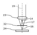
측정 물체들(24)의 높이 또는 두께를 측정하기 위한 본 발명에 따른 장치의 제1 실시예는 도 1을 참조하여 설명될 것이다. A first embodiment of a device according to the present invention for measuring the height or thickness of measurement objects 24 will be described with reference to Fig.
제시된 실시예에 있어서, 본 발명에 따른 장치는 보다 상세하게는 이들이 프로세싱될 때 웨이퍼들(24)의 형태인 측정 물체들(24)을 측정하고자 한다. In the embodiment shown, the apparatus according to the invention more specifically seeks to measure measurement objects 24 in the form of
도시된 바와 같이, 이 웨이퍼들(24)은 그 표면 상에 증착되는 하나 또는 그 이상의 얇은 층들(25)을 포함할 수 있다. As shown, the
이 웨이퍼들(24)은 예를 들어 450 ㎛내지 700 ㎛의 실리콘의 두께 및 수 나노미터에서 수 마이크론의 다른 투명한 유전체 또는 폴리이미드, 실리콘 산화물, 실리콘 니트라이드의 층을 포함할 수 있다. The
보통 이러한 얇은 층들은 가시광선 파장들에서 적어도 부분적으로 투명하다. 실리콘은 적외선 파장들에서 투명하다. 하지만, 샘플들에 따라서, 실리콘 층은 불투명한 층들(부품, 트랜지스터들, 금속 층들 또는 트랙들 등)을 포함할 수 있다. Usually these thin layers are at least partially transparent at visible light wavelengths. Silicon is transparent at infrared wavelengths. However, depending on the samples, the silicon layer may comprise opaque layers (parts, transistors, metal layers or tracks, etc.).
이러한 조건들 하에서, 상기에서 설명된 바와 같이, 웨이퍼의 전체 두께를 측정하기 위한 이미 알려진 방법들은, 특히 이들이 측정 파장들에서 투명할 때, 얇은 층들의 경계면들을 구분 또는 분석하기에 전반적으로 적절하지 않다. 이러한 층들의 두께를 측정하기를 원치 않고, 단지 웨이퍼(24)의 전체 두께만 측정하고자 한다면, 측정 정확도는 얇은 층들(25)의 경계면들의 검출에 있어서의 불확실성에 의해 제한된다. Under these conditions, as already explained above, the already known methods for measuring the overall thickness of the wafer are not generally suitable for discriminating or analyzing the interfaces of the thin layers, especially when they are transparent at the measured wavelengths . If we do not want to measure the thickness of these layers but only measure the total thickness of the
반대로, 충분히 넓은 범위의 주파수들을 가지는 스펙트럼을 가지는 광 소스를 이용해, 이러한 얇은 층들은 측정되거나 또는 그 경계면들이 주파수 도메인에서 작동하는 낮은-코히어런스 간섭계의 기술들을 이용해 구별될 수 있다. 그럼에도 불구하고, 이러한 기술들은, 홈이 있는 스펙트럼의 진동들이 검출기에 의해 샘플링되기에는 너무 가까워지기 때문에, (700 ㎛의 실리콘과 같이, 3.5 차수인, 실리콘의 굴절율을 고려한 후 2 mm 이상의 광학적 두께에 대응하는) 큰 광학적 두께들을 측정하기 위해서는 사용될 수 없다. Conversely, with a light source having a spectrum with a sufficiently wide range of frequencies, such thin layers can be measured or distinguished using techniques of low-coherence interferometers whose interfaces operate in the frequency domain. Nonetheless, these techniques are not compatible with optical thicknesses of more than 2 mm after consideration of the refractive index of silicon, which is a 3.5 order, such as 700 탆 silicon, since the vibrations of the groove spectrum are too close to being sampled by the detector Can not be used to measure large optical thicknesses.
게다가, 측정될 웨이퍼들(24)은 상당히 변형될 수 있는데, 이것은 넓은 측정 범위를 가지는 측정 시스템을 필요로 한다. In addition, the
본 발명에 따른 측정 장치의 핵심은 측정 헤드(10)에 통합되는 낮은-코히어런스 간섭계에 의해 구성된다. The core of the measuring device according to the invention is constituted by a low-coherence interferometer incorporated in the measuring
측정 헤드(10)는, 병진운동 단이 고정되는 장치의 프레임에 대하여 축 Z를 따라 변위되는 것을 허용하는, 동력에 의한 병진운동 단을 가지는 변위 수단(21)에 고정된다. 이 병진운동 단에는 광학적 측정자의 형태로 위치 정보 항목을 측정하기 위한 수단이 구비되어, 이 변위 및 그 위치가 정확하게 측정되게 해준다. The measuring
간섭계는 광대역 광 소스(11)에 의해 조명되는데, 이것은 가시광선 스펙트럼 내에서 다색 광(1)을 방출한다. 제시된 실시예에 있어서, 이 소스는 할로겐 소스, 또는 듀테륨 할로겐 소스를 포함하고, 이 스펙트럼은 자외부에서 30 nm까지 연장된다. The interferometer is illuminated by the
간섭계는 빔 분리기(13)를 포함하는데, 이것은 소스로부터 측정될 물체(24)로 광을 안내한다. The interferometer includes a
광의 일부는 기준 광학 빔(17)을 형성하기 위해, 반-반사 판(14)에 의해 구성되는 기준 표면(14) 상에서 반사된다.A portion of the light is reflected on a
소스로부터의 광의 일부는 측정 광학 빔(16)을 형성하기 위해, 반-반사 판(14)을 관통한다. 이 측정 광학 빔(16)은 대물렌즈 또는 렌즈(15)에 의해 측정될 물체(24)(웨이퍼(24)) 상에 촛점이 맞춰진다. A portion of the light from the source passes through the
측정 광학 빔(16)은 측정 물체(24)에 대하여 위치되어 그 광학 축(19)이 이 물체(24)의 경계면들에 실질적으로 수직하다. 제시된 실시예에 있어서, 이 광학 축(19)은 변위 수단(21)의 변위 축 Z에 실질적으로 평행하다. The measurement
측정 빔(16)의 광은 측정되는 물체(24)의 경계면들 상에서 특히, 도시된 예에 있어서, 얇은 층(25)의 경계면들에 의해, 반사된다. The light of the
반사된 측정 빔(16) 및 기준 빔(17)은 검출 분광계(18)로 빔 분리기(13)를 지나 안내된다. The reflected
이 분광계(18)는 회절 격자, 이것은 광학적 주파수들의 함수로서 측정 빔(16)과 기준 빔(17)의 결합 광을 공간적으로 분산시키고, 또한 선형 센서(CCD 또는 CMOS)를 포함하는데, 그 각각의 화소가 광학적 주파수들의 특정 범위에 대응하는 회절 격자로부터 발생하는 광을 수신한다. The
분광계는 컴퓨터(20)의 형태로 전자적 및 계산 수단(20)에 연결된다.The spectrometer is connected to the electronic and computing means 20 in the form of a
측정되는 물체(24)는, 도시된 실시예에 있어서, 웨이퍼(24)이고, 지지부(23) 상에 위치되는데, 이것은 웨이퍼 척(23)의 형태를 가진다. The
이 장치는 알려진 두께의 웨이퍼(26)의 일 부분의 형태로 기준 물체(26)를 더 포함한다. 이 기준 물체(26)는 웨이퍼 척(23) 상에 위치된다.The apparatus further includes a
웨이퍼 척(23)은 측정 빔(16)의 광학 축(19)에 실질적으로 수직하는 X-Y 평면에서 (예를 들어 장치의 프레임에 대하여) 그 변위를 보장하는 병진운동 단(22)의 형태로 제2 병진운동 수단(22) 상에 고정된다. The
이 제2 병진운동 수단(22)은 기준 물체(26) 상에 그리고 웨이퍼(24)의 표면의 모든 점에 측정 빔(16)을 위치시키는 것을 가능하게 해준다. This second translating
본 발명에 따른 장치는 측정 빔(16)에 반대되는 제2 면 상에 측정되는 물체(24) 상에 입사되는 제2 측정 빔(28)을 가지고 거리 및/또는 두께(27)를 측정하기 위한 제2 광학 수단을 더 포함한다. The apparatus according to the invention has a
제시된 실시예에 있어서, 이 제2 광학 측정 수단(27)은, 시간 지연선을 가지고, 시간 도메인에서 작동하는 낮은-코히어런스 간섭계(27)를 포함하는데, 이것은 광학적 경로에 있어서의 변화(variation) 또는 가변적인 지연을 도입하는 것을 가능하게 해준다. In the embodiment shown, this second optical measuring means 27 comprises a low-
이러한 간섭계들은 당업자에게 알려져 있어, 단지 일반적인 원리들만 여기에 소환될 것이다. Such interferometers are known to those skilled in the art, and only general principles will be recited herein.
넓은-스펙트럼 소스로부터 발생하는 광은 내부 기준 빔과 측정되는 물체 상에 입사되는 측정 빔(28)으로 분리된다. 측정 빔(28)은 물체의 경계면들 상에서 반사된다. 각각의 반사는 고려되는 경계면까지의 광학적 경로에 비례하는 지연에 종속된다. 이 지연은 지연선 내에서 재생되어 측정 및 기준 빔들을 다시 위상으로 가져오고 이로써 지연선의 변위 동안 간섭 피크들을 생성하게 된다. 이 지연선의 변위에 대한 이해는 간섭 피크들을 발생시키는 경계면들의 위치를 결정하는 것을 가능하게 해준다. The light originating from the wide-spectrum source is split into an internal reference beam and a
바람직하게 적외선의 광원이 사용되는데(예를 들어 대략 1310 nm), 이것은 실리콘을 관통하는 것을 가능하게 해주고 이로써 필요하다면 웨이퍼 내부의 층들 상에서 측정들을 수행하는 것을 가능하게 해준다. Preferably a source of infrared light is used (e.g., approximately 1310 nm), which allows penetration of the silicon and thereby makes it possible to perform measurements on the layers inside the wafer if necessary.
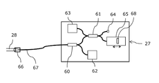
도 6은 시간 도메인에서 작동하는, 이 종류의 낮은-코히어런스 간섭계(27)의 대략적인 도시를 보여준다. Figure 6 shows a schematic view of this kind of low-
간섭계(27)의 핵심은, 인코딩 간섭계(60) 및 디코딩 간섭계(61)을 가지는, 단일 모드 광학섬유들에 기초한 이중 마이켈슨 간섭계이다. 이것은 섬유 광 소스(62)에 의해 조명되는데, 이것은 60 nm 차수의 스펙트럼 폭 및 그 중심 파장이 1310 nm 내지 1550 nm 차수인, 초발광 다이오드(superluminescent diode, SLD)이다. 이 파장의 선택은 특히 요소들의 이용가능성의 기준에 기초한다. The core of the
소스(62)로부터의 광은, 제2 측정 빔(28)을 구성하기 위해 커플러(60) 및 측정 광학섬유(67)를 통해 시준기(66)까지 안내되는데, 커플러는 인코딩 간섭계(60)로 구성된다. 소스(62)로부터 발생하는 빔의 일부는, 내부 기준 빔을 구성하기 위해, 시준기(66)에서 측정 섬유(67) 내에서 반사된다. 보다 상세하게는, 제시된 실시예에 있어서, 기준 빔은 시준기 안의 공기와 측정 광학섬유(67)의 끝단 사이의 경계면에서 프레즈넬 반사에 의해 생성된다. 이 반사는 대략 4% 정도이다. The light from the
웨이퍼(24)의 경계면들로부터 발생하는 역반사들은 섬유(67) 내에서 커플링되고 또한 섬유 커플러(61) 주위에 구축된 디코딩 간섭계(61)로 기준 파를 가지고 안내된다. 이 디코딩 간섭계는 그 2 개의 암들 각각이, 고정 기준(64) 및 시간 지연선(65)인, 광학적 상관기(optical correlator)로서 기능한다. 기준(64) 및 지연선(65)에서 반사된 신호들은, 커플러(61)를 통해, 광다이오드인, 검출기(63) 상에서 결합된다. 지연선(65)의 기능은 입사파와 반사파 사이의 광학적 지연을 도입하는 것이고, 이것은 알려진 방식으로 시간에 대하여 가변이다. 이 지연은 예를 들어 광학 빔의 축을 따라 움직이는, 미러(68)의 변위에 의해 획득된다. Retroreflections originating from the interfaces of the
디코딩 간섭계(61)의 암들(64 및 65)의 길이는 조정되어 지연선(65)을 가지고, 시준기(66)에서 반사되는 기준 파와 측정되는 물체(24)로부터의 역반사들 사이의 광학적 경로의 차이들을 재생하는 것을 가능하게 해준다. 이 광학적 경로의 차이가 미러(68)의 위치를 위해 재생될 때, 소스(62)의 스펙트럼 특성들에 따라 달라지는(소스(62)의 스펙트럼이 넓어질수록, 간섭 피크는 좁아지는), 간섭 피크 형태 및 그 폭이 검출기(43) 상에서 획득된다. The lengths of the
이로써, 측정 범위는 디코딩 간섭계(61)의 암들(64 및 65) 사이의 광학적 길이에 있어서의 차이에 의해, 및 지연선(65)의 최대 길이에 의해 결정된다. 이 종류의 간섭계들은 이로써 넓은 측정 범위들을 허용하는 장점을 가진다. 게다가, 측정되는 물체(24)의 연속하는 경계면들은 (예를 들어 미러(68)의 이동에 의해 재생되는 바와 같이) 이러한 경계면들을 분리하는 광학적 거리들에 의해 분리되는 간섭 피크들의 연속들로서 보이기 때문에, 다수의 층들의 스택들은 명확하게 측정될 수 있다. As such, the measurement range is determined by the difference in optical length between the
인코딩 간섭계(60) 및 디코딩 간섭계(61)를 가지는, 이중 간섭계 시스템을 구현하고, 또한 측정 섬유(67)의 끝단에서 기준을 생성하는 것에 의해, 시스템이 측정 섬유(67) 내의 섭동들에 민감하지 않도록 만드는 것이 가능하다. 이로써, 시준기와 측정되는 물체(24)의 경계면들 사이의 실제 광학적 거리들은 매우 정확하게 측정될 수 있다. By implementing a dual interferometer system with encoding
게다가, 측정 광학섬유(67)를 가지는 이 구성은 간섭계(27)를 멀리 이동시키는 것을 가능하게 해준다. 이로써, 단지 시준기(67)만 측정되는 물체(24) 근방에 있게 된다. 이것은 측정되는 물체(24)가 웨이퍼 척(23) 상의 웨이퍼(24)인 경우 중요한 장점인데, 이것은 웨이퍼 척(23) 상의 그 면을 통한 접근이 더 어렵기 때문이다. In addition, this configuration with the measuring
"캘리퍼" 구성에 있어서 측정되는 물체(24)의 일 측 상에서 2 개의 측정 빔들(16, 28)의 이용은, 측정 시스템들에 대하여 일 측 상의 그 면들의 거리들을 측정하는 것에 의해, 이 물체(24) 상의 두께의 측정들을 수행하는 것을 가능하게 해준다. 그러므로 사용되는 측정 파장들에서 투명하든, 불투명하든, 또는 부분적으로 불투명하든, 모든 경우들에 있어서, 물체(24)의 두께를 결정하는 것이 가능하다. The use of two
물론, 제2 병진운동 수단(22) 또한 제2 측정 빔(28)이 제1 측정 빔(16)에 반대되는 기준 물체(26)의 제2 면 상에, 또한 웨이퍼(24)의 제2 표면의 어떠한 점에 위치되도록 허용한다. Of course, the second translation means 22 also allows the
- 매우 넓은 스펙트럼을 가지는 광 소스를 이용해 또한 주파수 도메인에서 작동하는 낮은-코히어런스 간섭의 기술- a technique of low-coherence interference operating in the frequency domain using a very broad spectrum light source
- 및 적외부에서 시간 도메인에서 작동하는 낮은-코히어런스 간섭의 기술, - a technique of low-coherence interference operating in the time domain outside the enemy,
- 상기에서 설명된 바와 같은 캘리퍼 구성에서의 결합은, 이러한 측정 기술들의 큰 상보성으로 인해, 유전체의 얇은 층들을 가지는 웨이퍼들과 같은 샘플들의 매우 완전한 특성을 허용한다는 것에 유의해야 한다. It should be noted that the coupling in the caliper configuration as described above allows very complete characteristics of the samples, such as wafers with thin layers of dielectric due to the large complementarity of these measurement techniques.
도 2 및 도 3은 측정 빔(16) 및 기준 빔(17)을 공간적으로 분리하는 장점을 가지는 간섭계의 실시예들의 변형들을 보여준다. 이러한 구성들은 특히 측정 빔(16)과 기준 빔(17) 사이의 광학적 경로의 차이를 증가시키지 않고 간섭계와 측정되는 물체(24) 사이의 작업 거리를 증가시키는 것을 가능하게 해준다. Figures 2 and 3 show variants of embodiments of the interferometer having the advantage of spatially separating the
도 2는 마이켈슨 간섭계의 구성을 보여준다. 소스로부터의 광은 물체(24) 상으로 안내되는 측정 빔(16) 및 미러(14)의 형태인 기준 표면 상으로 안내되는 기준 빔(17)을 형성하기 위해 분리기 큐브(31)에 의해 분리된다. 측정 및 기준 빔들은 실질적으로 수직이다. Figure 2 shows the configuration of a Michelson interferometer. The light from the source is separated by the
도 3은 미라우 간섭계의 구성을 보여준다. 소스로부터의 광은 물체(24) 상으로 안내되는 측정 빔(16) 및 미러(14)의 형태인 기준 표면 상으로 안내되는 기준 빔(17)을 형성하기 위해 입사 빔의 광학 축(19)에 거의 수직인 반-반사 판(32)에 의해 분리된다. 이 경우에 있어서 기준 미러(14)는 입사 빔의 광학 축(19) 상에 있어, 중심 차광을 형성하게 된다. 3 shows the configuration of a micro-interferometer. The light from the source is incident on the
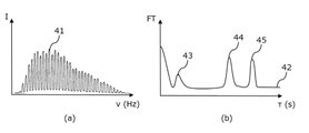
도 4(a)는 분광계(18)의 출력에서 획득되는 것과 같은 홈이 있는 스펙트럼 신호(41)를 보여준다. Fig. 4 (a) shows a spectrally scaled
이 신호는 광학적 주파수(ν)의 함수로서 표현되는 스펙트럼 세기 I(ν)를 나타낸다. 이 세기 I(ν)는 그 각각이 분광계(18) 상에 입사되는 2 개의 파들 사이의 간섭 신호에 대응되는 i 조화 함수들의 합으로서 나타낼 수 있다: This signal represents the spectral intensity I (v) expressed as a function of the optical frequency (v). This intensity I (v) can be represented as the sum of the i harmonics corresponding to the interference signal between the two waves, each of which is incident on the spectrometer 18:
I(ν) ~ A 0 (ν) + ∑ i { A i (ν) cos[(2π/c) 2L i ν+ φ i ] } I (ν) ~ A 0 ( ν) + Σ i {A i (ν) cos [(2π / c) 2L i ν + φ i]}
이때 Ao 및 Ai는 세기 계수들이고, φi는 위상 계수이고, c는 광의 속도이고, 2Li는 2 개의 간섭하는 파들 사이의 광학적 경로 차이이다. Where Ao and Ai are intensity coefficients,? I is a phase coefficient, c is the speed of light, and 2Li is the optical path difference between two interfering waves.
"이 조화 함수들 각각의 스펙트럼 변조의 "주파수"는 (사실 시간의 차원을 가지고 또한 간섭하는 2 개의 파들 사이의 지연에 대응하는)&Quot; The " frequency " of the spectral modulation of each of these harmonics functions (which in fact corresponds to the delay between the two waves interfering with the dimension of time)
τ i = (2L i /c).τ i = (2L i / c) .
로 기재될 수 있다. . ≪ / RTI >
이 스펙트럼 변조의 "주파수"는 그러므로 간섭하는 2 개의 파들 사이의 광학적 경로의 차이 2Li를 나타낸다. The " frequency " of this spectrum modulation thus represents the difference 2Li of the optical path between the two interfering waves.
스펙트럼 세기 I(ν)의 신호를 분석하기 위해, 퓨리에 변환이 이에 수행되고, 도 4(b)에 도시된 바와 같이, 진폭 스펙트럼 또는 스펙트럼 변조 신호(42)가 획득된다. 이 스펙트럼 변조 신호(42)는 측정 빔(16) 및 기준 빔(17)의 시간의 자기상관 함수의 엔벨롭을 나타내는 것에 유의해야 한다. 이것은 간섭하는 2 개의 파들 사이의 광학적 경로의 차이 2Li에 대응되는 각각의 지연 τ i 에 대한 진폭 피크(43, 44, 45)를 포함한다. To analyze the signal of the spectral intensity I (v), a Fourier transform is performed on it and an amplitude spectrum or spectral modulated
도 4(b)에 도시된 스펙트럼 변조 신호(42)는 도 1에 도시된 상황에 질적으로 대응되는데, 여기서 얇은 층(25)을 가지는 측정 물체(24)를 가진다. The spectral modulated
물론, 도 4(a) 및 도 4(b)에 도시된 신호들은 순수하게 도시된 것이다. Of course, the signals shown in Figs. 4 (a) and 4 (b) are shown purely.
스펙트럼 변조 신호(42)는 광학적 경로 차이 2E에 대응되는 지연 τ에 중심이 맞춰진 제1 피크(43)를 포함하는데, E는 얇은 층(25)의 광학적 두께이다. 제1 피크(43)은 그러므로 얇은 층(25)의 일 측 상에 위치되는 물체(24)의 2 개의 경계면들 상에서 반사되는 측정 빔(16)의 2 개의 성분들 사이의 간섭에 대응한다. The spectral modulated
이것은 또한 그 각각이 얇은 층(25)의 일 측 상에 위치되는 물체(24)의 개별적인 경계면들 상에서 반사되는 측정 빔(16)의 성분들과 기준 빔(17) 사이의 간섭들에 대응하는 제2 피크(44) 및 제3 피크(45)를 포함한다. Which also corresponds to interferences between the
단지 이러한 제2 및 제3 피크들(44, 45) 및 연관된 스펙트럼 변조 주파수들은 측정 광학 빔(16)과 기준 광학 빔(17) 사이의 광학적 경로 차이를 나타낸다. 그러므로, 이러한 제2 및 제3 피크들(44, 45)만 물체의 절대적인 높이에 대한 정보를 포함한다. Only these second and
그러므로, 물체(24) 상에서 높이 측정을 수행하기 위해, 측정 빔(16)의 성분들 사이의 간섭들에 의한 피크들(43) 및 이것만 유용한 정보를 포함하는 기준 빔(17)과 측정 빔(16) 사이의 간섭들로 인한 관심 피크들(44, 45)이 구분될 수 있어야 한다. A
이를 위해, 측정 헤드(10)는 변위 수단(21)을 가지고 측정되는 물체(24)에 대하여 변위되는데, 이것은 측정 빔(16)과 기준 빔(17) 사이의 광학적 경로 차이를 변화시키게 된다. 기준 빔(17)과 측정 빔(16) 사이의 간섭들로 인한 관심 피크들(44, 45)만 측정 범위에서 변위되고, 이것이 이들이 정지 상태로 남아 있는 나머지들과 구별되는 것을 가능하게 해준다. 게다가, 이로써 이들을 좋은 조건들 하에서 구별 및 측정될 수 있는 측정 범위의 바람직한 영역에 위치시키는 것이 가능하다. 이를 위해, 관심 피크들(44, 45)은: To this end, the measuring
- 이용가능한 측정 범위에 위치된다(지연들 τ 또는 광학적 경로 차이들 2L의 측면에서). 이 측정 범위는 0(0 지연)으로부터 스펙트럼 변조 주파수들이 더 이상 분광계의 스펙트럼 해상도로 인해 샘플링될 수 없는 지연들까지 연장된다. - in the available measurement range (in terms of delays tau or optical path differences 2L). This measurement range extends from 0 (zero delay) to delays where the spectral modulation frequencies can no longer be sampled due to the spectral resolution of the spectrometer.
- 바람직하게 물체(24)의 얇은 층들(25)의 두께에 대응하는 것보다 더 큰 지연들 τ 또는 광학적 경로 차이들 2L에 대응하는 측정 범위의 영역에 위치된다. Is preferably located in the region of the measurement range corresponding to delays? Or optical path differences 2L that are larger than those corresponding to the thickness of the
물체(24)의 얇은 층(25)의 두께가 충분히 크다면, 측정 헤드(10)는 또한 물체(24)에 대하여 위치되어 얇은 층(25)의 개별적인 경계면들에 의해 반사될 때 기준 광학 빔(17)의 광학적 경로의 길이가 측정 빔(16)의 광학적 경로들의 길이들 사이의 중간에 있을 수 있다. 이 경우에 있어서, 기준 표면(14)은 얇은 층(25)의 경계면들 사이에 있는 것처럼 광학적으로 보이고, 관심 피크들(44, 45)은 물체(24)의 얇은 층(25)의 두께에 대응하는 것보다 작은 지연들 τ(또는 광학적 경로 차이들 2L)에 위치된다. If the thickness of the
- 이로써 전체 측정 범위는 변위 수단(21)의 타격에 의해 필수적으로 결정되고, Whereby the entire measuring range is essentially determined by the impact of the displacement means 21,
- 해상도, 즉 근접한 경계면들을 구별할 수 있는 능력은, 스펙트럼 검출의 해상도에 의해 결정되는 것에 유의해야 한다. It should be noted that the resolution, i.e. the ability to distinguish adjacent boundaries, is determined by the resolution of the spectral detection.
상기에서 설명된 바와 같이, 간섭계는 물체(24)의 경계면들에 의해 반사되는 측정 빔과 기준 빔 사이의 광학적 경로 차이들(2Li)을 결정하는 것을 가능하게 해준다. 그러므로 간섭계 내에서 광학적 경로의 등가성에 의해 정의되는 원점에 대한 이 경계면들의 광학적 높이들(Li)을 결정하는 것을 가능하게 해준다. As described above, the interferometer makes it possible to determine the optical path differences 2Li between the measurement beam and the reference beam reflected by the interfaces of the
광학적 거리들 또는 높이들은 가로지르는 매체의 굴절율에 의해 곱해지는 기하학적 거리들 또는 높이들에 대응한다는 것이 상기될 것이다. 도 1의 실시예에 있어서, 이 높이들 Li는 Z 축을 따라 물체(24)의 경계면들과 기준 표면(14) 사이의 광학적 거리에 대응한다. It will be recalled that the optical distances or heights correspond to geometric distances or heights that are multiplied by the refractive index of the transverse medium. In the embodiment of FIG. 1, these heights Li correspond to the optical distance between the interface surfaces of the
도 1에 도시된 바와 같은 좌표 시스템(X, Y, Z)의 원점에 대한 물체(24)의 경계면들의 광학적 높이 Hui를 계산하기 위해, Z 축을 따라 측정 헤드(10)의 또는 간섭계의 위치 PH를 고려하는 것이 필요하다. 이 위치 PH는, 조정(calibration) 후 병진운동 단(21)의 위치 측정 수단에 의해 주어진다. Z 축을 따라 방향지어지는 광학적 거리들 Hui 및 위치 PH를 고려하여, 물체(24)의 경계면들의 광학적 높이 Hui는To calculate the optical height Hui of the interfaces of the
Hui = PH - LiHui = P H - Li
의 관계에 의해 주어진다.. ≪ / RTI >
제2 광학적 측정 수단(27)을 가지고 유사한 방식으로 그 반대되는 면 상의 측정 물체(24)의 경계면들의 광학적 높이 Hlj의 측정들을 획득하는 것 또한 가능하다. 바람직하게, 광학적 높이 Hlj의 이 측정들은 좌표 시스템(X, Y, Z)의 동일한 원점에 대하여 측정된다. It is also possible to obtain measurements of the optical height Hlj of the interfaces of the measuring
물체의 광학적 두께들 T는 그후 물체(24)의 2 개의 면들 상에서 획득되는 광학적 높이들 Hu 및 Hl를 더하는 것(또는 부호 규칙에 따른 감산)에 의해 결정될 수 있다. The optical thicknesses T of the object can then be determined by adding optical heights Hu and Hl (or subtraction in accordance with the code rules) obtained on two sides of the
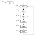
도 5를 참조하면, 본 발명의 장치를 사용하는 거리들 및/또는 두께를 측정하기 위한 방법이 이제 설명될 것이다. Referring now to FIG. 5, a method for measuring distances and / or thickness using the apparatus of the present invention will now be described.
측정을 수행하기 위해: To perform the measurement:
- 측정 빔은 제2 병진운동 수단(22)을 이용해 측정되는 물체(24)의 표면 상에 위치된다(단계 50); The measuring beam is located on the surface of the
- 측정 헤드(10)는 측정 빔(16)과 기준 빔(17) 사이의 광학적 경로 차이를 변화시키기 위한 변위 수단(21)을 가지고, 측정되는 물체(24)에 대하여 Z 방향으로 변위된다(단계 51); The measuring
- 관심 피크 또는 피크들(44, 45)은 상기에서 설명된 바와 같이 확인되거나 및/또는 측정 범위의 바람직한 영역 내에 위치된다(단계 52); The interest peaks or
- 이 관심 피크들(44, 45)에 대응하는 광학적 경로 차이 또는 차이들 Li는 (측정 빔(16)과 기준 빔(17)의 광학적 경로들의 등가성에 대응하는 0 지연에 대하여) 간섭계의 측정 범위 내에서 측정된다(단계 53); The optical path differences or differences Li corresponding to these
- 상기에서 설명된 바와 같이 간섭계의 위치 PH를 고려하여, 물체(24)의 경계면들의 광학적 높이 Hui는 계산된다(단계 54); Taking into account the position P H of the interferometer as described above, the optical height Hui of the interfaces of the
- 물체의 두께를 계산하기 위해, 측정 물체(24)의 경계면들의 광학적 높이 Hlj의 측정 또한 제2 광학적 측정 수단(27)을 가지고 그 반대 면 상에서 수행되고, 광학적 높이들 Hu 및 Hl은 (광학적) 두께 T를 결정하기 위해 결합된다(단계 55). A measurement of the optical height Hlj of the interfaces of the measuring
측정 빔들은 그후 다른 측정을 수행하고 이로써 물체(24)의 매핑 또는 토폴로지를 생성하기 위해 물체(24)의 표면의 다른 점으로 이동될 수 있다. The measurement beams can then be moved to different points on the surface of the
측정 헤드(10)의 변위의 단계 51은 관심 피크들의 확인이 유지된다면 물체의 표면에서 측정 점들 사이에서 생략될 수 있다. The
본 발명에 따른 방법은 또한, Z 축을 따라 측정 헤드(10) 또는 간섭계의 위치 PH의 값을 결정하는 것을 가능하게 해주는, 조정 단계 56을 포함한다. 이를 위해, 하나 또는 그 이상의 측정들이 그 높이 Hu가 알려진 기준 물체(26) 상에서 수행되고, 위치 PH의 값은 이로부터 추정된다. 유사한 방식으로, 제2 광학적 측정 수단(27)을 조정하는 것이 가능하다. The method according to the invention also comprises an
이 조정 절차는 물체(24)의 표면 상에서의 측정들의 세트를 수행하기 전에 한번 수행될 수 있다. This adjustment procedure may be performed once before performing a set of measurements on the surface of the
물론, 본 발명은 설명된 예들에 한정되지 않고 수많은 조정들이 본 발명의 범위를 초과하지 않으면서 이 예들에 적용될 수 있다. Of course, the invention is not limited to the described examples, and numerous adjustments may be made to these examples without exceeding the scope of the invention.
Claims (18)
다색 광(12)에 의해 조명되고 또한 하나의 분광계(18)에서, 기준 표면(14) 상에서 이 광의 반사로부터 발생하는 기준 광학 빔(17)과 상기 측정 물체(24)의 경계면들 상에서 이 광의 반사들로부터 발생하는 측정 광학 빔(16)을 결합하기 위해 배치되어, 스펙트럼 변조 주파수들을 가지는 홈이 있는 스펙트럼 신호(41)를 생성하게 되는, 제1 낮은-코히어런스 간섭계를 포함하고,
- 상기 측정 광학 빔(16)과 상기 기준 광학 빔(17)의 상대적인 광학적 길이를 변경시키기 위한 수단(21), 및 상기 상대적인 광학적 길이를 나타내는 위치 정보 항목을 측정하기 위한 수단,
- 상기 측정 광학 빔(16)과 상기 기준 광학 빔(17) 사이의 광학적 경로의 차이를 나타내는 적어도 하나의 스펙트럼 변조 주파수를 결정하고, 또한 상기 위치 정보 항목 및 상기 적어도 하나의 스펙트럼 변조 주파수를 이용하는 것에 의해, 상기 측정 물체(24) 상의 적어도 하나의 높이 및/또는 두께를 결정하기 위해 배치되는 전자적 및 계산 수단(20), 및
- 상기 측정 빔(16)에 반대되는 제2 면 상에 상기 측정 물체(24) 상에 입사되는 제2 측정 빔(28)을 가지고 거리 및/또는 두께(27)를 측정하기 위한 제2 광학적 수단을 더 포함하는 것을 특징으로 하는, 장치. An apparatus for measuring heights and / or thicknesses on a measurement object (24), such as a wafer,
Is illuminated by the polychromatic light 12 and in a single spectrometer 18 on the interface surfaces of the reference optical beam 17 and the measurement object 24 resulting from the reflection of this light on the reference surface 14, And a first low-coherence interferometer arranged to couple the measurement optical beam (16) originating from the first low-coherence interferometer
- means (21) for changing the relative optical length of the measuring optical beam (16) and the reference optical beam (17), means for measuring a position information item indicating the relative optical length,
- determining at least one spectral modulation frequency indicative of a difference in the optical path between the measurement optical beam (16) and the reference optical beam (17), and also using the position information item and the at least one spectral modulation frequency Electronic and computing means (20) arranged to determine at least one height and / or thickness on the measuring object (24)
Or - a second optical means for measuring the distance and / or thickness (27) with a second measuring beam (28) incident on the measuring object (24) on a second surface opposite to the measuring beam ≪ / RTI >
- 주파수-도메인 낮은-코히어런스 간섭계,
- 공촛점 시스템,
종류들 중 하나의 거리 및/또는 두께(27)를 측정하기 위한 제2 광학 수단을 포함하는, 장치. 9. The method according to any one of claims 1 to 8,
- frequency-domain low-coherence interferometer,
- Confocal systems,
And second optical means for measuring the distance and / or thickness (27) of one of the types.
다색 광(12)에 의해 조명되고 또한 하나의 분광계(18)에서, 기준 표면(14) 상에서 이 광의 반사로부터 발생하는 기준 광학 빔(17)과 상기 측정 물체(24)의 경계면들 상에서 이 광의 반사들로부터 발생하는 측정 광학 빔(16)을 결합하기 위해 배치되어, 스펙트럼 변조 주파수들을 가지는 홈이 있는 스펙트럼 신호(41)를 생성하게 되는, 제1 낮은-코히어런스 간섭계를 이용하고,
- 상기 측정 광학 빔(16)과 상기 기준 광학 빔(17)의 상대적인 광학적 길이를 나타내는 위치 정보 항목을 측정하는 단계,
- 상기 측정 광학 빔(16)과 상기 기준 광학 빔(17) 사이의 광학적 경로의 차이를 나타내는 적어도 하나의 스펙트럼 변조 주파수를 결정하는 단계,
- 상기 위치 정보 항목 및 상기 적어도 하나의 스펙트럼 변조 주파수를 이용하는 것에 의해, 상기 측정 물체(24) 상의 적어도 하나의 높이 및/또는 두께를 결정하는 단계,
- 상기 측정 빔(16)에 반대되는 제2 면 상에 상기 측정 물체(24) 상에 입사되는 제2 측정 빔(28)을 가지고 거리 및/또는 두께를 측정하기 위한 제2 광학적 수단을 이용해 높이 및/또는 두께들에 대한 제2 정보 항목을 측정하여, 상기 측정되어야 할 물체의 두께 정보 항목을 결정하는 단계를 더 포함하는 것을 특징으로 하는, 방법.A method for measuring heights and / or thicknesses on a measurement object (24), such as a wafer,
Is illuminated by the polychromatic light 12 and in a single spectrometer 18 on the interface surfaces of the reference optical beam 17 and the measurement object 24 resulting from the reflection of this light on the reference surface 14, Using a first low-coherence interferometer arranged to combine the measurement optical beam (16) emanating from the first spatial light modulator (12) and generating a spectrally-scaled spectral signal (41) with spectral modulating frequencies,
- measuring a positional information item indicative of the relative optical length of the measurement optical beam (16) and the reference optical beam (17)
- determining at least one spectral modulation frequency indicative of a difference in optical path between the measurement optical beam (16) and the reference optical beam (17)
- determining at least one height and / or thickness on the measurement object (24) by using the position information item and the at least one spectral modulation frequency,
A second measuring beam (28) which is incident on the measuring object (24) on a second surface opposite to the measuring beam (16), and a second optical means for measuring the distance and / And / or measuring a second information item on thicknesses to determine a thickness information item of the object to be measured.
- 상기 홈이 있는 스펙트럼 신호(41)의 퓨리에 변환의 진폭을 나타내는 스펙트럼 변조 신호(42)를 계산하는 단계,
- 상기 스펙트럼 변조 신호(42)에서 스펙트럼 변조 주파수들을 나타내는 진폭 피크들(43, 44, 45)을 확인하는 단계를 더 포함하는, 방법. 16. The method according to any one of claims 13 to 15,
- calculating a spectral modulated signal (42) representative of the amplitude of the Fourier transform of said grooved spectral signal (41)
- identifying amplitude peaks (43, 44, 45) representative of the spectral modulation frequencies in said spectral modulated signal (42).
- 측정 광학섬유(67) 및 시준기(66)를 이용해 제2 기준 광학 빔 및 상기 제2 측정 광학 빔(28)을 생성하는 단계,
- 시간 지연선이 마련된, 인코딩 간섭계(60) 및 디코딩 간섭계(61)를 가지는 이중 마이켈슨 간섭계를 이용해, 상기 측정 물체(24) 상에서 반사되는 상기 제2 측정 광학 빔(28)과 상기 기준 빔 사이의 광학적 경로의 차이를 결정하는 단계를 포함하는, 방법. 18. A method according to any one of claims 13 to 17, wherein the measurement of the second information item with respect to height and /
- generating a second reference optical beam and the second measuring optical beam (28) using the measuring optical fiber (67) and the collimator (66)
Using a dual Michelson interferometer with an encoding interferometer (60) and a decoding interferometer (61) with a time delay line between the second measurement optical beam (28) and the reference beam reflected on the measurement object (24) And determining a difference in the optical path of the light beam.
Applications Claiming Priority (3)
| Application Number | Priority Date | Filing Date | Title |
|---|---|---|---|
| FR1563128A FR3045813B1 (en) | 2015-12-22 | 2015-12-22 | DEVICE AND METHOD FOR MEASURING HEIGHT IN THE PRESENCE OF THIN FILMS |
| FR1563128 | 2015-12-22 | ||
| PCT/EP2016/080005 WO2017108400A1 (en) | 2015-12-22 | 2016-12-07 | Device and method for measuring height in the presence of thin layers |
Publications (1)
| Publication Number | Publication Date |
|---|---|
| KR20180098255A true KR20180098255A (en) | 2018-09-03 |
Family
ID=55346108
Family Applications (1)
| Application Number | Title | Priority Date | Filing Date |
|---|---|---|---|
| KR1020187017326A KR20180098255A (en) | 2015-12-22 | 2016-12-07 | Apparatus and method for measuring height in the presence of a thin layer |
Country Status (7)
| Country | Link |
|---|---|
| US (1) | US20180364028A1 (en) |
| EP (1) | EP3394560A1 (en) |
| KR (1) | KR20180098255A (en) |
| CN (1) | CN108431545A (en) |
| FR (1) | FR3045813B1 (en) |
| TW (1) | TW201728869A (en) |
| WO (1) | WO2017108400A1 (en) |
Families Citing this family (17)
| Publication number | Priority date | Publication date | Assignee | Title |
|---|---|---|---|---|
| FR3064349B1 (en) * | 2017-03-21 | 2023-06-30 | Fogale Nanotech | DEVICE AND METHOD FOR LOW COHERENCE REFLECTOMETRY WITH TIME-FREQUENCY DETECTION |
| TWI794416B (en) * | 2018-02-28 | 2023-03-01 | 美商賽格股份有限公司 | Metrology of multi-layer stacks and interferometer system |
| US10782120B2 (en) * | 2018-07-03 | 2020-09-22 | Kla Corporation | Dual-interferometry wafer thickness gauge |
| CN108917626A (en) | 2018-08-01 | 2018-11-30 | 深圳中科飞测科技有限公司 | A kind of detection device and detection method |
| CN109000571B (en) * | 2018-09-11 | 2021-05-14 | 中国科学院光电技术研究所 | Thickness consistency detection device |
| FR3089286B1 (en) * | 2018-11-30 | 2022-04-01 | Unity Semiconductor | Method and system for measuring a surface of an object comprising different structures by low coherence interferometry |
| DE102019102873B4 (en) * | 2019-02-06 | 2022-01-20 | Carl Mahr Holding Gmbh | Sensor system and method for determining geometric properties of a measurement object and coordinate measuring machine |
| CN110108716A (en) * | 2019-05-06 | 2019-08-09 | 华侨大学 | A kind of automation substrate wafer defect and thickness detecting system |
| DE102019114167A1 (en) * | 2019-05-27 | 2020-12-03 | Precitec Optronik Gmbh | Optical measuring device and method |
| CN112747681A (en) * | 2019-10-31 | 2021-05-04 | 佳陞科技有限公司 | Non-destructive optical detection system |
| CN115176147B (en) * | 2020-02-24 | 2024-05-10 | 诺威有限公司 | Optical metrology system and method |
| CN112762820A (en) * | 2020-12-11 | 2021-05-07 | 深圳市菲森科技有限公司 | Calibration device and calibration method of confocal three-dimensional measurement system |
| US11486694B2 (en) * | 2020-12-18 | 2022-11-01 | Mitutoyo Corporation | Chromatic range sensor system for measuring workpiece thickness |
| CN113483679B (en) * | 2021-07-06 | 2022-07-22 | 东北大学秦皇岛分校 | Contact lens parameter measuring device and method |
| CN113251936A (en) * | 2021-07-09 | 2021-08-13 | 成都太科光电技术有限责任公司 | Vertical semiconductor wafer TTV interference testing device |
| CN114166119A (en) * | 2021-11-29 | 2022-03-11 | 湖北亿纬动力有限公司 | Battery size measuring method, device, equipment and storage medium |
| EP4325166A1 (en) * | 2022-08-15 | 2024-02-21 | JENOPTIK Industrial Metrology Germany GmbH | Optical inspection apparatus |
Family Cites Families (12)
| Publication number | Priority date | Publication date | Assignee | Title |
|---|---|---|---|---|
| GB2301884A (en) | 1995-06-06 | 1996-12-18 | Holtronic Technologies Ltd | Characterising multilayer thin film systems by interferometry |
| JP5112588B2 (en) * | 2000-01-25 | 2013-01-09 | ザイゴ コーポレーション | Method and apparatus for measuring the shape and geometric dimensions of precision industrial parts |
| JP3907518B2 (en) * | 2002-05-13 | 2007-04-18 | 株式会社神戸製鋼所 | Shape measuring device |
| KR100988454B1 (en) * | 2008-01-31 | 2010-10-18 | 에스엔유 프리시젼 주식회사 | Method for measuring thickness |
| JP5473265B2 (en) * | 2008-07-09 | 2014-04-16 | キヤノン株式会社 | Multilayer structure measuring method and multilayer structure measuring apparatus |
| CN101509828B (en) * | 2009-03-06 | 2010-12-08 | 北京理工大学 | Differential confocal-low coherent interference combination refractivity and thickness measurement method and apparatus |
| CN102080949B (en) * | 2009-12-01 | 2013-11-06 | 无锡华润上华半导体有限公司 | Silicon epitaxial film thickness measuring method and device |
| FR2959305B1 (en) * | 2010-04-26 | 2014-09-05 | Nanotec Solution | OPTICAL DEVICE AND METHOD FOR INSPECTING STRUCTURED OBJECTS. |
| US9714825B2 (en) * | 2011-04-08 | 2017-07-25 | Rudolph Technologies, Inc. | Wafer shape thickness and trench measurement |
| FR2994734B1 (en) * | 2012-08-21 | 2017-08-25 | Fogale Nanotech | DEVICE AND METHOD FOR MAKING DIMENSION MEASUREMENTS ON MULTI-LAYER OBJECTS SUCH AS WAFERS. |
| ITBO20130403A1 (en) * | 2013-07-26 | 2015-01-27 | Marposs Spa | METHOD AND EQUIPMENT FOR OPTICAL CONTROL BY INTERFEROMETRY OF THE THICKNESS OF A PROCESSED OBJECT |
| FR3026481B1 (en) * | 2014-09-25 | 2021-12-24 | Fogale Nanotech | SURFACE PROFILOMETRY DEVICE AND METHOD FOR IN-PROCESS WAFER CONTROL |
-
2015
- 2015-12-22 FR FR1563128A patent/FR3045813B1/en active Active
-
2016
- 2016-12-07 US US16/061,268 patent/US20180364028A1/en not_active Abandoned
- 2016-12-07 WO PCT/EP2016/080005 patent/WO2017108400A1/en active Application Filing
- 2016-12-07 EP EP16816597.5A patent/EP3394560A1/en not_active Withdrawn
- 2016-12-07 KR KR1020187017326A patent/KR20180098255A/en unknown
- 2016-12-07 CN CN201680074722.9A patent/CN108431545A/en active Pending
- 2016-12-14 TW TW105141398A patent/TW201728869A/en unknown
Also Published As
| Publication number | Publication date |
|---|---|
| WO2017108400A1 (en) | 2017-06-29 |
| CN108431545A (en) | 2018-08-21 |
| TW201728869A (en) | 2017-08-16 |
| FR3045813A1 (en) | 2017-06-23 |
| EP3394560A1 (en) | 2018-10-31 |
| FR3045813B1 (en) | 2020-05-01 |
| US20180364028A1 (en) | 2018-12-20 |
Similar Documents
| Publication | Publication Date | Title |
|---|---|---|
| KR20180098255A (en) | Apparatus and method for measuring height in the presence of a thin layer | |
| US9714825B2 (en) | Wafer shape thickness and trench measurement | |
| US9587932B2 (en) | System for directly measuring the depth of a high aspect ratio etched feature on a wafer | |
| KR101842291B1 (en) | Optical Device and Method for Inspecting Structured Objects | |
| KR102549714B1 (en) | Optical phase measurement method and system | |
| KR101815325B1 (en) | System for directly measuring the depth of a high aspect ratio etched feature on a wafer | |
| JP7138734B2 (en) | Dual interferometric sample thickness gauge | |
| KR20200118218A (en) | Measurement of multilayer stacks | |
| EP2998693B1 (en) | Surface-geometry measurement method and device used therein | |
| US20080174785A1 (en) | Apparatus for the contact-less, interferometric determination of surface height profiles and depth scattering profiles | |
| US20100183188A1 (en) | Optical measuring device | |
| JP2006250826A (en) | Measuring element, processing device and measuring method, and measuring element of refractive index | |
| KR101541602B1 (en) | Optical gap sensor apparatus and the gap sensing method thereof for measuring multi-degree of freedom measurements | |
| JP2005084019A (en) | Temperature measuring method of substrate | |
| US20150022817A1 (en) | Profilometer with partial coherence interferometer adapted for avoiding... | |
| CN107894204B (en) | Interferometer and imaging method thereof | |
| KR101722815B1 (en) | Measuring method of surface of specimen and measurement apparatus of surface of specimen | |
| CN110603423B (en) | Apparatus and method for low coherence reflection with time-frequency detection | |
| US10890434B2 (en) | Inspecting a multilayer sample | |
| JP2010014536A (en) | Measuring method and measuring apparatus for object under measurement mounted on processing apparatus | |
| US11885609B2 (en) | Wafer thickness, topography, and layer thickness metrology system | |
| JP2008309638A (en) | Dimension measuring device and dimension measuring method | |
| Hall | Rapid thickness and profile measurement of bonded multi-layer structures | |
| Skiba et al. | Displacement measurement method for advanced electronic packaging | |
| JPH1183637A (en) | Method for evaluating coherence of semiconductor laser |