KR20180058729A - Arthroscopic device - Google Patents
Arthroscopic device Download PDFInfo
- Publication number
- KR20180058729A KR20180058729A KR1020187009053A KR20187009053A KR20180058729A KR 20180058729 A KR20180058729 A KR 20180058729A KR 1020187009053 A KR1020187009053 A KR 1020187009053A KR 20187009053 A KR20187009053 A KR 20187009053A KR 20180058729 A KR20180058729 A KR 20180058729A
- Authority
- KR
- South Korea
- Prior art keywords
- assembly
- curved
- snare wire
- bone
- drive
- Prior art date
Links
Images


Classifications
-
- A—HUMAN NECESSITIES
- A61—MEDICAL OR VETERINARY SCIENCE; HYGIENE
- A61B—DIAGNOSIS; SURGERY; IDENTIFICATION
- A61B17/00—Surgical instruments, devices or methods, e.g. tourniquets
- A61B17/16—Bone cutting, breaking or removal means other than saws, e.g. Osteoclasts; Drills or chisels for bones; Trepans
- A61B17/1642—Bone cutting, breaking or removal means other than saws, e.g. Osteoclasts; Drills or chisels for bones; Trepans for producing a curved bore
-
- A—HUMAN NECESSITIES
- A61—MEDICAL OR VETERINARY SCIENCE; HYGIENE
- A61B—DIAGNOSIS; SURGERY; IDENTIFICATION
- A61B17/00—Surgical instruments, devices or methods, e.g. tourniquets
- A61B17/00234—Surgical instruments, devices or methods, e.g. tourniquets for minimally invasive surgery
-
- A—HUMAN NECESSITIES
- A61—MEDICAL OR VETERINARY SCIENCE; HYGIENE
- A61B—DIAGNOSIS; SURGERY; IDENTIFICATION
- A61B17/00—Surgical instruments, devices or methods, e.g. tourniquets
- A61B17/04—Surgical instruments, devices or methods, e.g. tourniquets for suturing wounds; Holders or packages for needles or suture materials
- A61B17/0469—Suturing instruments for use in minimally invasive surgery, e.g. endoscopic surgery
-
- A—HUMAN NECESSITIES
- A61—MEDICAL OR VETERINARY SCIENCE; HYGIENE
- A61B—DIAGNOSIS; SURGERY; IDENTIFICATION
- A61B17/00—Surgical instruments, devices or methods, e.g. tourniquets
- A61B17/04—Surgical instruments, devices or methods, e.g. tourniquets for suturing wounds; Holders or packages for needles or suture materials
- A61B17/0482—Needle or suture guides
-
- A—HUMAN NECESSITIES
- A61—MEDICAL OR VETERINARY SCIENCE; HYGIENE
- A61B—DIAGNOSIS; SURGERY; IDENTIFICATION
- A61B17/00—Surgical instruments, devices or methods, e.g. tourniquets
- A61B17/04—Surgical instruments, devices or methods, e.g. tourniquets for suturing wounds; Holders or packages for needles or suture materials
- A61B17/06—Needles ; Sutures; Needle-suture combinations; Holders or packages for needles or suture materials
- A61B17/062—Needle manipulators
- A61B17/0625—Needle manipulators the needle being specially adapted to interact with the manipulator, e.g. being ridged to snap fit in a hole of the manipulator
-
- A—HUMAN NECESSITIES
- A61—MEDICAL OR VETERINARY SCIENCE; HYGIENE
- A61B—DIAGNOSIS; SURGERY; IDENTIFICATION
- A61B17/00—Surgical instruments, devices or methods, e.g. tourniquets
- A61B17/16—Bone cutting, breaking or removal means other than saws, e.g. Osteoclasts; Drills or chisels for bones; Trepans
- A61B17/1604—Chisels; Rongeurs; Punches; Stamps
-
- A—HUMAN NECESSITIES
- A61—MEDICAL OR VETERINARY SCIENCE; HYGIENE
- A61B—DIAGNOSIS; SURGERY; IDENTIFICATION
- A61B17/00—Surgical instruments, devices or methods, e.g. tourniquets
- A61B17/16—Bone cutting, breaking or removal means other than saws, e.g. Osteoclasts; Drills or chisels for bones; Trepans
- A61B17/1613—Component parts
- A61B17/1615—Drill bits, i.e. rotating tools extending from a handpiece to contact the worked material
-
- A—HUMAN NECESSITIES
- A61—MEDICAL OR VETERINARY SCIENCE; HYGIENE
- A61B—DIAGNOSIS; SURGERY; IDENTIFICATION
- A61B17/00—Surgical instruments, devices or methods, e.g. tourniquets
- A61B17/56—Surgical instruments or methods for treatment of bones or joints; Devices specially adapted therefor
-
- A—HUMAN NECESSITIES
- A61—MEDICAL OR VETERINARY SCIENCE; HYGIENE
- A61B—DIAGNOSIS; SURGERY; IDENTIFICATION
- A61B17/00—Surgical instruments, devices or methods, e.g. tourniquets
- A61B17/04—Surgical instruments, devices or methods, e.g. tourniquets for suturing wounds; Holders or packages for needles or suture materials
- A61B17/0483—Hand-held instruments for holding sutures
-
- A—HUMAN NECESSITIES
- A61—MEDICAL OR VETERINARY SCIENCE; HYGIENE
- A61B—DIAGNOSIS; SURGERY; IDENTIFICATION
- A61B17/00—Surgical instruments, devices or methods, e.g. tourniquets
- A61B17/04—Surgical instruments, devices or methods, e.g. tourniquets for suturing wounds; Holders or packages for needles or suture materials
- A61B17/06—Needles ; Sutures; Needle-suture combinations; Holders or packages for needles or suture materials
- A61B17/06004—Means for attaching suture to needle
- A61B2017/06028—Means for attaching suture to needle by means of a cylindrical longitudinal blind bore machined at the suture-receiving end of the needle, e.g. opposite to needle tip
-
- A—HUMAN NECESSITIES
- A61—MEDICAL OR VETERINARY SCIENCE; HYGIENE
- A61B—DIAGNOSIS; SURGERY; IDENTIFICATION
- A61B17/00—Surgical instruments, devices or methods, e.g. tourniquets
- A61B17/04—Surgical instruments, devices or methods, e.g. tourniquets for suturing wounds; Holders or packages for needles or suture materials
- A61B17/06—Needles ; Sutures; Needle-suture combinations; Holders or packages for needles or suture materials
- A61B17/06004—Means for attaching suture to needle
- A61B2017/06042—Means for attaching suture to needle located close to needle tip
-
- A—HUMAN NECESSITIES
- A61—MEDICAL OR VETERINARY SCIENCE; HYGIENE
- A61B—DIAGNOSIS; SURGERY; IDENTIFICATION
- A61B17/00—Surgical instruments, devices or methods, e.g. tourniquets
- A61B17/04—Surgical instruments, devices or methods, e.g. tourniquets for suturing wounds; Holders or packages for needles or suture materials
- A61B17/06—Needles ; Sutures; Needle-suture combinations; Holders or packages for needles or suture materials
- A61B17/06066—Needles, e.g. needle tip configurations
- A61B2017/0608—J-shaped
Landscapes
- Health & Medical Sciences (AREA)
- Life Sciences & Earth Sciences (AREA)
- Surgery (AREA)
- Molecular Biology (AREA)
- General Health & Medical Sciences (AREA)
- Biomedical Technology (AREA)
- Heart & Thoracic Surgery (AREA)
- Medical Informatics (AREA)
- Nuclear Medicine, Radiotherapy & Molecular Imaging (AREA)
- Animal Behavior & Ethology (AREA)
- Engineering & Computer Science (AREA)
- Public Health (AREA)
- Veterinary Medicine (AREA)
- Orthopedic Medicine & Surgery (AREA)
- Dentistry (AREA)
- Oral & Maxillofacial Surgery (AREA)
- Surgical Instruments (AREA)
Abstract
뼈에 제 1의 및 제 2의 전반적인 직선 채널의 형성 다음에 유용한 관절경 뼈 채널 형성 및 봉합 시스템으로서, 제 2 채널은 제 1 채널과 교차하지 않으며, 시스템은, 제 1 채널 내로 삽입될 수 있도록 구성된 만곡형 뼈 천자 바늘, 제 1 채널과 제 2 채널 사이에 만곡된 접합부를 형성하도록 만곡형 바늘을 조작하도록 구성된 만곡형 바늘 구동 어셈블리, 뼈의 제 2 채널을 통해 봉합사 스네어 와이어 픽-업 위치로 봉합사 스네어 와이어를 삽입하도록 구성된 봉합사 스네어 와이어 어셈블리, 및 봉합사 스네어 와이어가 봉합사 픽 업 위치로부터 접합부를 통해 제 1 채널을 통해서 당겨지게끔 만곡형 바늘 구동 어셈블리 및 봉합사 스네어 와이어 어셈블리를 협조된 동작으로 동작시키기 위하여 동작이 가능한 협조 다기능 구동 어셈블리를 포함한다.A system for forming and sealing an arthroscopic bone channel that is useful following the formation of first and second general linear channels in a bone, wherein the second channel does not intersect the first channel and the system is adapted to be inserted into the first channel A curved needle puncture needle configured, a curved needle drive assembly configured to manipulate the curved needle to form a curved joint between the first channel and the second channel, a curved needle drive assembly configured to move the suture wire to the suture snare wire pick- A suture snare wire assembly configured to insert a suture snare wire and a suture snare wire assembly configured to operatively move the curved needle drive assembly and the suture snare wire assembly from the suture pick up position through the abutment through the first channel And includes a cooperating multifunctional drive assembly operable to operate the machine.
Description
관련 출원들에 대한 참조Reference to Related Applications
본 출원과 관련된 것으로 여겨지는 다음의 PCT 특허 출원들 및 미국 가특허 출원들에 대한 참조가 이루어지며, 이로써 이들의 내용들이 본원에 참조로서 포함된다:Reference is made to the following PCT patent applications and US patent applications which are regarded as relating to the present application, the contents of which are incorporated herein by reference:
"Arthroscopic Surgical Device"라는 명칭으로 2014년 09월 09일에 공개된 공개 PCT 특허 출원 제WO/2014/147619호;Published PCT Patent Application No. WO / 2014/147619, entitled "Arthroscopic Surgical Device ", issued on September 09, 2014;
"Arthroscopic Surgical Device"라는 명칭으로 2013년 07월 11일에 공개된 공개 PCT 특허 출원 제WO/2013/102909호.Published PCT Patent Application No. WO / 2013/102909, entitled "Arthroscopic Surgical Device ", issued Jul. 11,
"Arthroscopic Surgical Device"라는 명칭으로 2013년 02월 28일에 공개된 공개 PCT 특허 출원 제WO/2013/027209호.Published PCT Patent Application No. WO / 2013/027209, published February 28, 2013 entitled "Arthroscopic Surgical Device ".
"Circular Bone Tunneling Device Employing a Stabilizing Element"라는 명칭으로 2013년 02월 28일에 공개된 공개 PCT 특허 출원 제WO/2013/027210호.Published PCT Patent Application No. WO / 2013/027210, published February 28, 2013 entitled " Circular Bone Tunneling Device Employing a Stabilizing Element ".
"Circular Bone Tunneling Device"라는 명칭으로 2011년 07월 1일에 공개된 공개 PCT 특허 출원 제2012/007941호.Published PCT Patent Application No. 2012/007941, entitled " Circular Bone Tunneling Device "
"Arthroscopic Surgical Device"라는 명칭으로 2013년 03월 18일에 출원된 미국 가특허 출원 일련번호 제61/802,958호.No. 61 / 802,958 filed on March 18, 2013 entitled "Arthroscopic Surgical Device ".
"Arthroscopic Surgical Device"라는 명칭으로 2013년 10월 07일에 출원된 미국 가특허 출원 일련번호 제61/887,561호.U. S. Patent Application Serial No. 61 / 887,561, filed October 07, 2013 entitled "Arthroscopic Surgical Device ".
"Circular Bone Tunneling Device Employing a Stabilizing Element"라는 명칭으로 2012년 04월 23일에 출원된 미국 가특허 출원 일련번호 제61/636,751호;U. S. Patent Application Serial No. 61 / 636,751, filed April 23, 2012 entitled " Circular Bone Tunneling Device Employing a Stabilizing Element ";
"Circular Bone Tunneling Device"라는 명칭으로 2011년 08월 24일에 출원된 미국 가특허 출원 일련번호 제61/526,717호;U.S. Provisional Patent Application Serial No. 61 / 526,717 filed on August 24, 2011 entitled "Circular Bone Tunneling Device";
"Arthroscopic Surgical Device"라는 명칭으로 2012년 10월 17일에 출원된 미국 가특허 출원 일련번호 제61/714,813호; 및U. S. Patent Application Serial No. 61 / 714,813, filed October 17, 2012 under the name "Arthroscopic Surgical Device "; And
"Circular Bone Tunneling Device"라는 명칭으로 2012년 01월 08일에 출원된 미국 가특허 출원 일련번호 제61/584,267호.U.S. Provisional Patent Application Serial No. 61 / 584,267 filed on January 08, 2012 entitled " Circular Bone Tunneling Device ".
기술분야Technical field
본 발명은 관절경 수술 디바이스들에 관한 것으로서, 더 구체적으로는 관절경 뼈 터널링(bone tunneling) 디바이스들에 관한 것이다.The present invention relates to arthroscopic surgical devices, and more particularly to arthroscopic bone tunneling devices.
정형외과 수술을 포함하여 다양한 애플리케이션들에 대하여 다양한 유형들의 관절경 수술 기구들이 공지되어 있다.Various types of arthroscopic instruments are known for a variety of applications, including orthopedic surgery.
용어들 '터널' 및 '채널'이 본 발명의 설명에서 상호교환적으로 사용되며 이들이 뼈에 형성된 원통형의 원형 중공 구멍(hollow bore)과 같은 중공 구멍을 지칭한다는 것이 이해될 것이다. 용어들 '터널링(tunneling)' 및 '채널링(channeling)'이 본 발명의 설명에서 상호교환적으로 사용되며 이들이 뼈에 원통형의 원형 중공 구멍과 같은 중공 구멍을 형성하는 방법을 지칭한다는 것이 또한 이해될 것이다.It will be appreciated that the terms " tunnels " and " channels " are used interchangeably in the description of the present invention and refer to hollow holes such as cylindrical circular hollow bores formed in the bone. It will also be appreciated that the terms " tunneling " and " channeling " are used interchangeably in the description of the present invention and refer to a method in which they form hollow holes, such as cylindrical hollow holes, will be.
본 발명의 설명 전체에 걸쳐 사용되는 용어 "봉합사(suture)"는 임의의 적절한 봉합사를 지칭하며, 또한 뼈를 통해 봉합사를 당기기 위해 사용되는 전달 와이어(transfer wire)를 지칭한다는 것, 및 본 발명의 설명 전체에 걸쳐 사용되는 용어 "스네어 와이어(snare wire)"의 사용이 전달 와이어 또는 봉합사 중 하나를 지칭한다는 것이 추가로 이해될 것이다. 전형적으로, 전달 와이어는 본 발명의 시스템 및 방법과 함께 사용되며, 니티놀로 형성된다. 전형적으로, 본 발명의 시스템 및 방법과 함께 사용되는 전달 와이어는 일 단부에 루프(loop)를 형성하기 위하여 접힌다.The term "suture " used throughout the description of the present invention refers to any suitable suture and also refers to a transfer wire used to pull the suture through the bone, It will be further understood that the use of the term "snare wire " as used throughout the description refers to either the delivery wire or the suture. Typically, a delivery wire is used with the system and method of the present invention and is formed of Nitinol. Typically, the transmission wire used with the system and method of the present invention is folded to form a loop at one end.
본 발명의 설명 전체에 걸쳐 사용되는 용어 "6각 렌치"는 일반적으로는 "L" 형상으로 형성된 6각형의 길이 방향 형상을 갖는 임의의 적절한 렌치를 지칭한다는 것이 추가로 이해될 것이다. 6각 렌치는 또한 때때로 알렌 렌치들 또는 6각 키(key)들로서 지칭된다.It will be further understood that the term "hexagonal wrench" used throughout the description of the present invention refers to any suitable wrench having a hexagonal, longitudinal shape generally formed in an "L" The hexagonal wrenches are also sometimes referred to as Allen wrenches or hexagonal keys.
본 발명은 개선된 관절경 뼈 터널링 및 봉합 디바이스를 제공하는 것을 추구한다.The present invention seeks to provide an improved arthroscopic bone tunneling and sealing device.
따라서, 본 발명의 선호되는 실시예에 따르면, 뼈에 제 1의 전반적인 직선 채널을 형성하도록 구성된 펀치(punch) 및 뼈에 제 2의 전반적인 직선 채널을 형성하도록 구성된 드릴에 유용한 관절경 뼈 채널 형성 및 봉합 시스템이 제공되며, 시스템은, 제 1의 전반적인 직선 채널 내로 삽입이 가능하도록 구성된 만곡형(curved) 뼈 천자(puncture) 바늘, 제 1의 전반적인 직선 채널과 제 2의 전반적인 직선 채널 사이에 만곡된 접합부(junction)를 형성하기 위하여 만곡형 바늘을 조작하도록 구성된 만곡형 바늘 구동(driving) 어셈블리, 뼈의 제 2의 전반적인 직선 채널을 통해 봉합사 스네어 와이어 픽-업(pick-up) 위치로 봉합사 스네어 와이어를 삽입하도록 구성된 봉합사 스네어 와이어 어셈블리, 및 봉합사 스네어 와이어가 봉합사 픽 업 위치로부터 그리고 접합부를 통해 제 1의 전반적인 직선 채널을 통해서 당겨지게끔 만곡형 바늘 구동 어셈블리 및 봉합사 스네어 와이어 어셈블리를 협조된 동작으로 동작시키기 위하여 동작이 가능한 협조(coordinated) 다기능 구동 어셈블리를 포함한다.Thus, according to a preferred embodiment of the present invention, arthroscopic bone channel formation for use in a punch configured to form a first overall linear channel in bone and a drill configured to form a second overall linear channel in bone, and There is provided a stitching system comprising a curved bone puncture needle configured to be insertable into a first overall linear channel, a curved needle threaded between a first generally straight channel and a second generally straight channel, A curved needle driving assembly configured to manipulate a curved needle to form a junction, a suture snare wire to a pick-up position through a second general linear channel of the bone, , And a suture snare wire assembly configured to receive the suture snare wire from the suture pick up position and through the abutment In order to operate in cooperation with one of the overall typically gets pulled through the straight channel and the curved needle drive assembly suture snare wire assembly operation and a possible coordination (coordinated) multi-functional drive assembly operation.
바람직하게는, 협조 다기능 구동 어셈블리는 반복되는 수동 작동들에 응답하여 자동으로 동작한다. 추가적으로 또는 대안적으로, 협조 다기능 구동 어셈블리는, 만곡형 바늘이 제 1의 전반적인 직선 채널 내에 삽입되기 시작한 이후에 그렇지만 만곡형 바늘이 접합부를 통해 봉합사를 당기는 것을 시작하기 이전에 만곡형 바늘을 인출(withdraw)하도록 선택적으로 동작하는 오버라이드(override) 서브-어셈블리를 포함한다.Preferably, the coordinated multifunctional drive assembly operates automatically in response to repeated manual operations. Additionally or alternatively, the cooperating multifunctional drive assembly may be configured to withdraw the curved needle after the curved needle begins to be inserted into the first overall straight channel, but before the curved needle begins to pull the suture through the abutment and an override sub-assembly that selectively operates to withdraw the data.
본 발명의 선호되는 실시예에 따르면, 관절경 뼈 채널 형성 및 봉합 시스템은 또한 관절경 수술 디바이스, 작업 채널 어셈블리, 스네어 와이어 카트리지 어셈블리 및 만곡형 샤프트 어셈블리를 포함한다. 추가적으로 또는 대안적으로, 관절경 뼈 채널 형성 및 봉합 시스템은 또한 뼈 펀치 어셈블리, 빠른 연결 엘리먼트, 드릴 비트(drill bit) 어셈블리 및 수동 오버라이드 기어 시프터(shifter) 중 적어도 하나를 포함한다.According to a preferred embodiment of the present invention, the arthroscopic bone channel forming and sealing system also includes an arthroscopic surgical device, a working channel assembly, a snare wire cartridge assembly, and a curved shaft assembly. Additionally or alternatively, the arthroscopic bone channel forming and sealing system also includes at least one of a bone punch assembly, a fast connection element, a drill bit assembly, and a manual override gear shifter.
바람직하게는, 작업 채널 어셈블리는, 중공 세장형(elongate) 튜브, 작업 채널 허브(hub), 그 안에 작업 채널 허브가 적어도 부분적으로 안착되는 랙-획정(rack-defining) 중간 엘리먼트, 및 유지 캡(retaining cap) 엘리먼트를 포함하며, 중공 세장형 튜브는 길이 방향 축을 따라 연장하고 작업 채널 허브 내에 형성된 소켓 내에 고정적으로 장착되는 경사진 전방 에지 및 후방 에지를 갖는다. 추가적으로, 작업 채널 허브는, 횡방향(transverse) 구멍을 갖는 전방 소켓-획정 부분, 전방 소켓-획정 부분 및 축 방향 중심 구멍의 후방에 배치되는 메인 원통형 부분, 및 후방 단부에 배치되는 플랜지(flange)를 포함하는 일체로 형성된 엘리먼트이다.Preferably, the working channel assembly includes a hollow elongate tube, a working channel hub, a rack-defining intermediate element in which the working channel hub is at least partially seated, and a retaining cap retaining cap element, the hollow elongate tube having a tapering front edge and a rear edge extending along a longitudinal axis and fixedly mounted within a socket formed in the working channel hub. Additionally, the working channel hub may include a front socket-defining portion having a transverse hole, a front socket-defining portion and a main cylindrical portion disposed behind the axial center hole, and a flange disposed at the rear end, As shown in Fig.
본 발명의 선호되는 실시예에 따르면, 랙-획정 중간 엘리먼트는, 길이 방향 축을 따라 연장하는 축 방향 구멍을 가지고 형성된 메인 원통형 부분 및 선형 래칫(ratchet) 기어 랙을 포함한다. 추가적으로 또는 대안적으로, 스네어 와이어 카트리지 어셈블리는, 메인 하우징 부분, 2차 하우징 부분, 메인 및 2차 하우징 부분들 상에 장착되는 세장형 중공 샤프트, 세장형 중공 샤프트 위에 장착되는 압축 스프링, 메인 하우징 부분 내에 장착되는 인장 스프링, 메인 하우징 부분 내에 위치되며 기어 티쓰(gear teeth)의 원형의 대칭적인 어레이를 갖는 스네어 와이어 권취(winding) 드럼, 루프가 세장형 중공 샤프트의 전방 단부에 위치되며 부분적으로 스네어 와이어 권취 드럼 둘레에 감긴 상태로 세장형 중공 내에 부분적으로 위치되며 미리-형성된 루프를 획정하는 스네어 와이어의 접힌 길이(folded over length), 및 스네어 와이어 권취 드럼과 함께 동작하는 스네어 와이어 인장 엘리먼트를 포함한다.According to a preferred embodiment of the present invention, the rack-defining intermediate element comprises a main cylindrical portion and a linear ratchet gear rack formed with an axial bore extending along the longitudinal axis. Additionally or alternatively, the snare wire cartridge assembly may include a main housing portion, a secondary housing portion, a elongated hollow shaft mounted on the main and secondary housing portions, a compression spring mounted on the elongated hollow shaft, A snare wire winding drum positioned within the main housing portion and having a symmetrical array of circular teeth of gear teeth, a loop positioned at the front end of the elongate hollow shaft, A folded over length of the snare wire partially positioned within the elongated hollow and wrapped around the take-up drum to define a pre-formed loop, and a snare wire tension element that cooperates with the snare wire take-up drum.
본 발명의 선호되는 실시예에 따르면, 인장 엘리먼트는, 중심 개구 및 경사진 스프링 맞물림 표면 및 접합부 맞물림 표면을 획정하는 스프링 맞물림 돌출부를 갖는 디스크(disc) 부분 및 전반적으로 스프링 맞물림 돌출부에 대향되는 방향으로 디스크 부분으로부터 밖으로 방사상으로 연장하며 스네어 와이어 권취 드럼의 기어 티쓰의 원형의 대칭적인 어레이와 래칫-형 맞물림을 위하여 구성된 기어 티쓰의 만곡된 선형 어레이를 포함하는 가요성 래칫 기어 맞물림 부분을 포함한다. 추가적으로, 스네어 와이어 권취 드럼 상의 인장 하에서 감긴 스네어 와이어를 당기는 것은, 스네어 와이어 권취 드럼이 메인 하우징 부분의 접합부와의 스프링 맞물림 돌출부의 접합부 맞물림 표면의 맞물림에 기인하여 더 이상 회전할 수 없을 때까지 스네어 와이어 권취 드럼을 스프링의 강제(urging)에 대하여 회전시키며, 이에 의하여 스네어 와이어에 대한 계속되는 당김은 스네어 와이어가 스네어 와이어 권취 드럼으로부터 자유롭게 풀려서 세장형 중공 샤프트를 통해 전방으로 끌어 당겨지는 것을 가능하게 한다.According to a preferred embodiment of the present invention, the tensioning element comprises a disc portion having a central opening and an inclined spring engaging surface and a spring engaging projection for defining a engaging engagement surface, and a disc portion generally in a direction opposite to the spring engaging projection And a flexible ratchet gear engagement portion extending radially outward from the disc portion and including a linear symmetrical array of gear teeth of the snare-wire take-up drum and a curved linear array of gear teeth configured for ratchet-type engagement. Additionally, pulling the coiled snare wire under tension on the snare-wire take-up drum will cause the snare-wire take-up drum to rotate further until the snare-wire take-up drum is no longer able to rotate due to engagement of the abutment engagement surface of the spring- The spinning drum is rotated about the urging of the spring so that the subsequent pulling on the snare wire allows the snare wire to be freely released from the snare-wire take-up drum and pulled forward through the elongate hollow shaft.
바람직하게는, 만곡형 샤프트 어셈블리는 만곡형 샤프트 어셈블리 외부 엘리먼트들의 쌍, 만곡형 샤프트 어셈블리 내부 엘리먼트들의 쌍, 및 만곡형 샤프트 어셈블리 내부 엘리먼트들의 쌍의 대응하는 단부들에 맞물리며 관절경 수술 디바이스 내의 고정된 축 상 위치에 유지되고, 관절경 수술 디바이스에 대하여 만곡형 샤프트 어셈블리의 위치의 축 방향 조정 능력을 제공하는 만곡형 샤프트 어셈블리 위치결정(location) 링을 포함한다.Preferably, the curved shaft assembly engages a pair of curved shaft assembly outer elements, a pair of curved shaft assembly inner elements, and corresponding ends of a pair of curved shaft assembly inner elements, And a curved shaft assembly locating ring maintained in an axial position and providing axial adjustment of the position of the curved shaft assembly relative to the arthroscopic device.
본 발명의 선호되는 실시예에 따르면, 만곡형 뼈 천자 바늘은, 약간 둥근 배후(back) 단부 표면으로부터 테이퍼진(tapered) 팁(tip)까지 연장하는 방사상으로 안쪽을 향한 전반적으로 만곡된 에지(edge) 표면, 배후 단부 표면에서의 전반적으로 둥글지 않은 코너로부터 상단 돌출부까지 그리고 여기를 넘어서 이로부터 전방으로 방사상으로 바깥쪽을 향한 전반적으로 만곡된 표면 부분이 연장하는 숄더(shoulder)까지 연장하는 후방의 방사상으로 바깥쪽으로 향한 전반적으로 만곡된 표면 부분, 및 각각이 테이퍼진 팁 측면 표면을 포함하는 만곡된 측면 표면들의 쌍을 갖도록 형성된다.According to a preferred embodiment of the present invention, the curved bone puncture needle comprises a radially inwardly generally curved edge extending from a slightly rounded back end surface to a tapered tip, ) Surface, a rearwardly extending portion extending from the generally non-rounded corner at the rear end surface to the top protrusion, and extending from the base to the shoulder extending generally beyond the radially outwardly radially outward surface portion thereof A generally radially outwardly curved surface portion, and a pair of curved side surfaces each including a tapered tip side surface.
바람직하게는, 관절경 수술 디바이스는, 제 1 및 제 2 하우징 부분들, 제 1 및 제 2 하우징 부분들에 의해 둘러싸인 관절경 수술 메커니즘, 구동 방향 선택기 레버 및 제 1 및 제 2 하우징 부분들을 함께 만곡형 샤프트 어셈블리 위에 그리고 이와 맞물리게 유지하기 위하여 동작하는 유지 콘(retaining cone)을 포함한다. 추가적으로, 관절경 수술 메커니즘은 작업 채널 어셈블리의 견인(retraction)을 위하여 동작할 수 있는 다음의 엘리먼트들을 포함한다: 다수의 기어 티쓰의 각각 상에 구동 표면들을 획정하여 결과적으로 선형 래칫 기어 트랙과 맞물려서 작업 채널 어셈블리의 부분을 형성하는 래칫 기어, 이의 제 1 단부 상에 래칫 기어가 장착되는 원통형 액슬(axle)을 포함하며 바람직하게는 이와 일체로 형성되는 액슬-장착형 기어, 스프링 단부 암(arm)들의 코일 쌍을 갖는 회전 강제(urging) 스프링, 및 관절경 수술 디바이스에 대하여 작업 채널 어셈블리를 선택적으로 로킹(lock)하고 릴리즈(release)하는 작업 채널 어셈블리 유지 후크(hook) 엘리먼트.Preferably, the arthroscopic device includes an arthroscopic surgical mechanism surrounded by the first and second housing portions, the first and second housing portions, the drive direction selector lever and the first and second housing portions, Type shaft assembly and a retaining cone that operates to engage and retain the same. In addition, the arthroscopic surgical mechanism includes the following elements that can operate for retraction of the working channel assembly: defining drive surfaces on each of the plurality of gear teeth and consequently engaging the linear ratchet gear track A ratchet gear forming part of the channel assembly, an axle-mounted gear including a cylindrical axle on which a ratchet gear is mounted on a first end thereof, and which is preferably formed integrally therewith, a coil of spring end arms, And a working channel assembly retaining hook element for selectively locking and releasing the working channel assembly relative to the arthroscopic device.
본 발명의 선호되는 실시예에 따르면, 구동 방향 선택기 레버는 후방으로 및 전방으로 틸팅(tilt)된 동작 배향들을 갖는다.According to a preferred embodiment of the present invention, the drive direction selector lever has operating orientations tilted back and forward.
본 발명의 선호되는 실시예에 따르면, 관절경 수술 메커니즘은 또한 카트리지 어셈블리 유지 엘리먼트, 유지 암을 획정하는 카트리지 어셈블리 유지 스프링 및 수동 작동가능 구동 엔진 어셈블리를 포함한다. 추가적으로, 수동 작동가능 구동 엔진 어셈블리는 다음의 엘리먼트들 중 적어도 5개를 포함한다: 메인 섀시(chassis), 보조 섀시, 카트리지 푸셔(pusher), 카트리지 푸셔 커넥터, 손으로 쥘 수 있는 구동 핸들, 메인 구동 방향 시프팅 엘리먼트, 시프트가능(shiftable) 엘리먼트, 구동 방향 선택기 레버 응답 토글(toggle) 엘리먼트, 방향-시프팅 스프링, 후방 구동 기어 랙, 전방 구동 기어 랙, 클러치(clutch), 메인 구동 기어, 바늘 구동 래칫 암, 전방 구동 기어, 작업 채널 견인 래칫 암, 피봇가능(pivotable) 암 및 시프트가능 링크. 추가적으로 또는 대안적으로, 수동 작동가능 구동 엔진 어셈블리는 다음의 엘리먼트들 중 적어도 하나를 포함한다: 구동 핸들 스프링, 메인 구동 방향 시프팅 엘리먼트 스프링, 핸들 피봇 액슬, 구동 핀 및 래칫 암 강제 스프링.According to a preferred embodiment of the present invention, the arthroscopic surgical mechanism also includes a cartridge assembly retaining element, a cartridge assembly retention spring defining a retaining arm, and a manually operable drive engine assembly. Additionally, the manually operable drive engine assembly includes at least five of the following elements: a main chassis, a secondary chassis, a cartridge pusher, a cartridge pusher connector, a hand-held drive handle, a main drive A directional shifting element, a shiftable element, a drive direction selector lever response toggle element, a direction-shifting spring, a rear drive gear rack, a forward drive gear rack, a clutch, a main drive gear, A ratchet arm, a forward drive gear, a working channel towed ratchet arm, a pivotable arm and a shiftable link. Additionally or alternatively, the manually operable drive engine assembly includes at least one of the following elements: a drive handle spring, a main drive direction shifting element spring, a handle pivot axle, a drive pin and a ratchet arm forcible spring.
본 발명의 선호되는 실시예에 따르면, 카트리지 어셈블리 유지 엘리먼트의 분리는 작업 채널 어셈블리로부터의 스네어 와이어 카트리지 어셈블리의 즉각적이고 부분적인 축 방향 견인을 생성한다.According to a preferred embodiment of the present invention, detachment of the cartridge assembly retaining element creates an immediate and partial axial retraction of the snare wire cartridge assembly from the working channel assembly.
바람직하게는, 협조 다기능 구동 어셈블리는 메인 구동 축을 획정하며, 메인 구동 축에 대하여 120 도 내지 140 도로 각이 진 손으로 쥘 수 있는 구동 핸들 부분을 포함한다. 추가적으로 또는 대안적으로, 협조 다기능 구동 어셈블리는 메인 구동 축을 획정하며, 메인 구동 축에 대하여 132.5 도로 각이 진 손으로 쥘 수 있는 구동 핸들 부분을 포함한다.Preferably, the cooperating multifunctional drive assembly defines a main drive shaft and includes a hand gripable handle portion angled from 120 to 140 degrees with respect to the main drive shaft. Additionally or alternatively, the cooperating multifunction drive assembly defines a main drive shaft and includes a hand gripable handle portion angled at 132.5 degrees with respect to the main drive shaft.
본 발명의 다른 선호되는 실시예에 따른 스네어 와이어 카트리지 어셈블리가 제공되며, 스네어 와이어 카트리지 어셈블리는, 메인 하우징 부분, 2차 하우징 부분, 메인 및 2차 하우징 부분들 상에 장착되는 세장형 중공 샤프트, 세장형 중공 샤프트 위에 장착되는 압축 스프링, 메인 하우징 부분 내에 장착되는 인장 스프링, 메인 하우징 부분 내에 위치되며 기어 티쓰의 원형의 대칭적인 어레이를 갖는 스네어 와이어 권취 드럼, 루프가 세장형 중공 샤프트의 전방 단부에 위치되며 부분적으로 스네어 와이어 권취 드럼 둘레에 감긴 상태로 세장형 중공 내에 부분적으로 위치되며 미리-형성된 루프를 획정하는 스네어 와이어의 접힌 길이, 및 스네어 와이어 권취 드럼과 함께 동작하는 스네어 와이어 인장 엘리먼트를 포함한다.There is provided a snare wire cartridge assembly in accordance with another preferred embodiment of the present invention, wherein the snare wire cartridge assembly comprises a main housing portion, a secondary housing portion, a elongated hollow shaft mounted on the main and secondary housing portions, A compression spring mounted on the elongate hollow shaft, a tension spring mounted within the main housing portion, a snare wire retracting drum positioned within the main housing portion and having a symmetrical array of gear teeth, a loop disposed at the front end of the elongate hollow shaft And a snare wire tensioning element that partially cooperates with the snare wire winding drum, partially folded around the snare-wire winding drum and partially located within the elongated hollow, defining a pre-formed loop.
바람직하게는, 인장 엘리먼트는, 중심 개구 및 경사진 스프링 맞물림 표면 및 접합부 맞물림 표면을 획정하는 스프링 맞물림 돌출부를 갖는 디스크 부분 및 전반적으로 스프링 맞물림 돌출부에 대향되는 방향으로 디스크 부분으로부터 밖으로 방사상으로 연장하며 스네어 와이어 권취 드럼의 기어 티쓰의 원형의 대칭적인 어레이와 래칫-형 맞물림을 위하여 구성된 기어 티쓰의 만곡된 선형 어레이를 포함하는 가요성 래칫 기어 맞물림 부분을 포함한다.Preferably, the tensioning element comprises a disk portion having a central opening and an inclined spring engaging surface and a spring engaging projection defining a abutment engaging surface, and a disk portion extending radially outwardly from the disk portion in a direction generally opposite the spring engaging projection, And a flexible ratchet gear engagement portion comprising a symmetrical array of gear teeth of a wire-winding drum and a curved linear array of gear teeth configured for ratchet-type engagement.
본 발명의 선호되는 실시예에 따르면, 스네어 와이어 권취 드럼 상의 인장 하에서 감긴 스네어 와이어를 당기는 것은, 스네어 와이어 권취 드럼이 메인 하우징 부분의 접합부와의 스프링 맞물림 돌출부의 접합부 맞물림 표면의 맞물림에 기인하여 더 이상 회전할 수 없을 때까지 스네어 와이어 권취 드럼을 스프링의 강제에 대하여 회전시키며, 이에 의하여 스네어 와이어에 대한 계속되는 당김은 스네어 와이어가 스네어 와이어 권취 드럼으로부터 자유롭게 풀려서 세장형 중공 샤프트를 통해 전방으로 끌어 당겨지는 것을 가능하게 한다.According to a preferred embodiment of the present invention, pulling the snare wire wound under tension on the snare-wire take-up drum is no longer necessary due to the engagement of the snare-wire take-up drum with the abutment engagement surface of the spring- The snare wire winding drum is rotated about the spring force until it can not rotate so that the subsequent pulling on the snare wire causes the snare wire to be released from the snare wire winding drum and pulled forward through the elongate hollow shaft .
본 발명의 또 다른 선호되는 실시예에 따르면 만곡형 샤프트 어셈블리가 제공되며, 만곡형 샤프트 어셈블리는 만곡형 샤프트 어셈블리 외부 엘리먼트들의 쌍, 만곡형 샤프트 어셈블리 내부 엘리먼트들의 쌍, 및 만곡형 샤프트 어셈블리 내부 엘리먼트들의 쌍의 대응하는 단부들에 맞물리며 관절경 수술 디바이스 내의 고정된 축 상 위치에 유지되고, 관절경 수술 디바이스에 대하여 만곡형 샤프트 어셈블리의 위치의 축 방향 조정 능력을 제공하는 만곡형 샤프트 어셈블리 위치결정 링을 포함한다.According to another preferred embodiment of the present invention, a curved shaft assembly is provided, wherein the curved shaft assembly comprises a pair of curved shaft assembly outer elements, a pair of curved shaft assembly inner elements, and a pair of curved shaft assembly inner elements A pair of curved shaft assembly positioning rings that engage corresponding ends of the pair and are maintained in a fixed axial position within the arthroscopic device and provide axial adjustment of the position of the curved shaft assembly relative to the arthroscopic device .
바람직하게는, 외부 엘리먼트들은 금속으로 형성되며, 내부 엘리먼트들은 플라스틱으로 형성된다. Preferably, the outer elements are formed of metal and the inner elements are formed of plastic.
본 발명의 또 다른 선호되는 실시예에 따르면 만곡형 뼈 천자 바늘이 추가로 제공되며, 만곡형 뼈 천자 바늘은, 약간 둥근 후방 단부 표면으로부터 테이퍼진 팁까지 연장하는 방사상으로 안쪽을 향한 전반적으로 만곡된 에지 표면, 후방 단부 표면에서의 전반적으로 둥글지 않은 코너로부터 상단 돌출부까지 그리고 여기를 넘어서 이로부터 전방으로 방사상으로 바깥쪽을 향한 전반적으로 만곡된 표면 부분 및 각각이 테이퍼진 팁 측면 표면을 포함하는 만곡된 측면 표면들의 쌍이 연장하는 숄더까지 연장하는 후방의 방사상으로 바깥쪽으로 향한 전반적으로 만곡된 표면 부분을 포함한다.According to another preferred embodiment of the present invention, a curved bone puncture needle is additionally provided, wherein the curved bone puncture needle comprises a generally radially inwardly curved, generally curved bone needle extending from a slightly rounded rear end surface to a tapered tip Generally curved surface portions radially outwardly directed from the generally non-rounded corner to the top protrusion at and beyond the edge surface at the rear end surface, and a generally curved surface portion extending radially outwardly therefrom, And a rear radially outwardly generally curved surface portion extending to a shoulder extending from the pair of side surfaces.
본 발명의 또 다른 선호되는 실시예에 따르면 관절경 수술 디바이스가 추가로 제공되며, 관절경 수술 디바이스는, 제 1 및 제 2 하우징 부분들, 제 1 및 제 2 하우징 부분들에 의해 둘러싸인 관절경 수술 메커니즘, 구동 방향 선택기 레버 및 제 1 및 제 2 하우징 부분들을 함께 만곡형 샤프트 어셈블리 위에 그리고 이와 맞물리게 유지하기 위하여 동작하는 유지 콘을 포함한다.According to yet another preferred embodiment of the present invention, an arthroscopic surgical device is additionally provided, wherein the arthroscopic device comprises a first and a second housing portions, an arthroscopic surgeon surrounded by the first and second housing portions Mechanism, a drive direction selector lever, and a retaining cone operable to hold the first and second housing portions together and in engagement with the curved shaft assembly.
바람직하게는, 관절경 수술 메커니즘은 작업 채널 어셈블리의 견인을 위하여 동작할 수 있는 다음의 엘리먼트들: 다수의 기어 티쓰의 각각 상에 구동 표면들을 획정하여 결과적으로 선형 래칫 기어 트랙과 맞물려서 작업 채널 어셈블리의 부분을 형성하는 래칫 기어, 이의 제 1 단부 상에 래칫 기어가 장착되는 원통형 액슬을 포함하며 바람직하게는 이와 일체로 형성되는 액슬-장착형 기어, 스프링 단부 암들의 코일 쌍을 갖는 회전 강제 스프링, 및 관절경 수술 디바이스에 대하여 작업 채널 어셈블리를 선택적으로 로킹하고 릴리즈하는 작업 채널 어셈블리 유지 후크 엘리먼트를 포함한다.Advantageously, the arthroscopic surgical mechanism comprises the following elements operable for traction of the working channel assembly: defining drive surfaces on each of the plurality of gear teeth, resulting in engagement with the linear ratchet gear track, An axle-mounted gear including a cylindrical axle on which a ratchet gear is mounted, preferably integrally formed with the ratchet gear, a rotary urging spring having a coil pair of spring end arms, And a working channel assembly retention hook element for selectively locking and releasing the working channel assembly relative to the synoptome device.
본 발명의 선호되는 실시예에 따르면, 관절경 수술 메커니즘은 또한 카트리지 어셈블리 유지 엘리먼트, 유지 암을 획정하는 카트리지 어셈블리 유지 스프링; 및 수동 작동가능 구동 엔진 어셈블리를 포함한다.According to a preferred embodiment of the present invention, the arthroscopic surgical mechanism also includes a cartridge assembly retention element, a cartridge assembly retention spring defining a retaining arm; And a manually operable drive engine assembly.
본 발명의 또 다른 선호되는 실시예에 따르면 관절경 수술 디바이스가 제공되며, 관절경 수술 디바이스는, 메인 구동 축을 획정하며 메인 구동 축에 대하여 120 도 내지 140 도의 각도로 각이 진 손으로 쥘 수 있는 구동 핸들 부분을 포함하는 하우징을 포함한다.According to yet another preferred embodiment of the present invention, an arthroscopic surgical device is provided, wherein the arthroscopic device comprises an arthroscopic device, which defines a main drive shaft and is angled with an angle of 120 to 140 degrees relative to the main drive shaft And a housing including a drive handle portion.
바람직하게는, 손으로 쥘 수 있는 구동 핸들 부분은 메인 구동 축에 대하여 132.5 도의 각도로 각이 진다.Preferably, the hand-held drive handle portion is angled at an angle of 132.5 degrees with respect to the main drive shaft.
본 발명의 또 다른 선호되는 실시예에 따르면 뼈에 제 1의 전반적인 직선 채널 및 제 2의 전반적인 직선 채널의 형성 다음에 유용한 관절경 뼈 채널 형성 및 봉합 방법이 추가로 제공되며, 방법은, 만곡형 뼈 천자 바늘을 제 1의 전반적인 직선 채널 내에 삽입하는 단계, 제 1의 전반적인 직선 채널과 제 2의 전반적인 직선 채널 사이에 만곡된 접합부를 형성하기 위하여 만곡형 바늘을 조작하는 단계, 뼈의 제 2의 전반적인 직선 채널을 통해 봉합사 스네어 와이어 픽-업 위치에 봉합사 스네어 와이어를 삽입하는 단계, 및 봉합사 스네어 와이어가 봉합사 픽 업 위치로부터 그리고 접합부를 통해 제 1의 전반적인 직선 채널을 통해서 당겨지는 것을 초래하는 단계를 포함한다.According to another preferred embodiment of the present invention, there is additionally provided a method of forming and sealing an arthroscopic bone channel which is useful following the formation of a first general linear channel and a second general linear channel in the bone, Manipulating the curved needle to form a curved joint between the first overall linear channel and the second generally linear channel, inserting the bone puncture needle into the first overall linear channel, Inserting the suture snare wire into the suture snare wire pick-up position through the overall straight channel and causing the suture snare wire to be pulled through the first overall straight channel from the suture pick up position and through the abutment .
바람직하게는, 초래하는 단계는 반복되는 수동 작동들에 응답하여 동작한다. 추가적으로 또는 대안적으로, 관절경 뼈 채널 형성 및 봉합 방법은 또한, 만곡형 바늘이 제 1의 전반적인 직선 채널 내에 삽입되기 시작한 이후에 그렇지만 만곡형 바늘이 접합부를 통해 봉합사를 당기는 것을 시작하기 이전에 만곡형 바늘을 인출하는 단계를 포함한다.Preferably, the resulting step operates in response to repeated manual operations. Additionally or alternatively, the arthroscopic bone channel formation and suturing method may also be performed after the curved needle begins to be inserted within the first overall straight channel, but before the curved needle begins to pull the suture through the abutment, And withdrawing the needle.
도면들과 함께 취해질 때 다음의 상세한 설명으로부터 본 발명이 이해되고 인식될 것이다.
도 1a 및 도 1b는 대향되는 도면들을 도시하는 본 발명의 선호되는 실시예에 따라 구성되고 동작하는 관절경 수술 어셈블리의 간략화된 도식적 예시들이다.
도 2a 및 도 2b는 도 1a 및 도 1b의 관절경 수술 어셈블리의 부분을 형성하는 펀치 어셈블리의 간략화된 예시들이다.
도 3a 및 도 3b는 도 1a 및 도 1b의 관절경 수술 어셈블리의 부분을 형성하는 작업 채널 어셈블리의 간략화된 예시들이다.
도 3c, 도 3d, 도 3e 및 도 3f는 각기, 도 3a 및 도 3b의 작업 채널 어셈블리의 부분을 형성하는, 작업 채널 허브의 전방을 향한 도식적 예시; 후방을 향한 도식적 예시, 측면도 예시 및 전방을 향한 후방 단면도 예시이다.
도 3g, 도 3h, 도 3i 및 도 3j는 각기, 도 3a 및 도 3b의 작업 채널 어셈블리의 부분을 형성하는, 랙-획정 중간 엘리먼트의 전방을 향한 도식적 예시; 후방을 향한 도식적 예시, 측면도 예시 및 전방을 향한 후방 단면도 예시이다.
도 3k, 도 3l, 도 3m, 도 3n, 도 3o 및 도 3p는 각기, 도 3a 및 도 3b의 작업 채널 어셈블리의 부분을 형성하는, 유지 캡 엘리먼트의 전방을 향한 도식적 예시; 상단의 후방을 향한 도식적 예시, 하단의 후방을 향한 도식적 예시, 후방을 향한 전방 단면도 예시, 및 제 1 및 제 2 내부 측면도 예시들이다.
도 4a, 도 4b, 도 4c 및 도 4d는, 도 1a 및 도 1b의 관절경 수술 어셈블리의 부분을 형성하는 빠른 연결 엘리먼트의 간략화된 예시들이다.
도 5a 및 도 5b는, 도 1a 및 도 1b의 관절경 수술 어셈블리의 부분을 형성하는 드릴 비트 어셈블리의 간략화된 예시들이다.
도 6a, 도 6b, 도 6c 및 도 6d는, 도 1a 및 도 1b의 관절경 수술 어셈블리의 부분을 형성하는, 스네어 와이어 카트리지 어셈블리의 간략화된 개별적인 후방을 향한 도식적 예시 및 전방을 향한 도식적 예시, 및 후방을 향한 분해도 예시 및 전방을 향한 분해도 예시이다.
도 6e, 도 6f, 도 6g 및 도 6h는 스네어 와이어 카트리지 어셈블리의 메인 하우징 부분의 간략화된 개별적인 내부 평면도, 제 1 및 제 2 내부 도식도 및 후방을 향한 단면도 예시들이다.
도 6i, 도 6j, 도 6k 및 도 6l은 스네어 와이어 카트리지 어셈블리의 2차 하우징 부분의 간략화된 개별적인 내부 평면도, 제 1 및 제 2 내부 도식도 및 후방을 향한 단면도 예시들이다.
도 6m, 도 6n, 도 6o 및 도 6p는, 스네어 와이어 카트리지 어셈블리의 부분을 형성하는 스네어 와이어 권취 드럼의 간략화된 개별적인 평면도, 제 1 및 제 2 도식도 및 에지 도면 예시들이다.
도 6q 및 도 6r은 스네어 와이어 권취 드럼과 함께 동작하는 인장 엘리먼트의 간략화된 제 1 및 제 2 내부 도식도 예시들이다.
도 6s는 스네어 와이어 카트리지 어셈블리의 간략화된 측면도 예시이다.
도 7a, 도 7b, 도 7c, 도 7d, 도 7e, 도 7f, 도 7g, 도 7h, 도 7i, 도 7j, 도 7k, 도 7l, 도 7m, 도 7n, 도 7o, 도 7p는, 도 1a 및 도 1b의 관절경 수술 어셈블리의 부분을 형성하는 만곡형 샤프트 어셈블리의 간략화된 예시들이다.
도 8a, 도 8b, 도 8c, 도 8d, 도 8e, 도 8f, 도 8g, 도 8h, 도 8i, 도 8j, 도 8k, 도 8l, 도 8m, 도 8n, 도 8o, 도 8p, 도 8q, 도 8r, 도 8s, 도 8t, 도 8u, 도 8v, 도 8w, 도 8x, 도 8y, 도 8z, 도 8aa, 도 8ab, 도 8ac, 도 8ad, 도 8ae, 도 8af, 도 8ag, 도 8ah, 도 8ai, 도 8aj, 도 8ak, 도 8al, 도 8am, 도 8an, 도 8ao, 도 8ap, 도 8aq, 도 8ar, 도 8as, 도 8at, 도 8au, 도 8av, 도 8aw, 도 8ax, 도 8ay, 도 8az, 도 8ba, 도 8bb, 도 8bc, 도 8bd, 도 8be, 도 8bf, 도 8bg, 도 8bh, 도 8bi, 도 8bj, 도 8bk, 도 8bl, 도 8bm, 도 8bn, 도 8bo, 도 8bp, 도 8bq, 도 8br, 도 8bs, 도 8bt, 및 도 8bu는, 도 1a 및 도 1b의 관절경 수술 어셈블리의 부분을 형성하는 관절경 수술 디바이스의 간략화된 예시들이다.
도 9a, 도 9b 및 도 9c는, 도 1a 및 도 1b의 관절경 수술 어셈블리의 동작에 유용한 수동 오버라이드 엘리먼트의 간략화된 개별적인 상면도, 측면도 및 저면도 예시들이다.
도 9d, 도 9e 및 도 9f는, 도 1a 및 도 1b의 관절경 수술 어셈블리의 동작에서의 수동 오버라이드의 개별적인 애플리케이션들의 간략화된 예시들이다.
도 10a, 도 10b, 도 10c, 도 10d, 도 10e, 도 10f, 도 10g, 도 10h, 도 10i, 도 10j, 도 10k, 도 10l, 도 10m, 도 10n, 도 10o, 도 10p, 도 10q, 도 10r, 도 10s, 도 10t, 도 10u, 도 10v, 도 10w, 도 10x, 도 10y, 도 10z, 도 10aa, 도 10ab, 도 10ac, 도 10ad, 도 10ae, 도 10af, 도 10ag, 도 10ah, 도 10ai, 도 10aj, 도 10ak, 도 10al, 도 10am 및 도 10an은 도 1a 내지 도 9f의 관절경 수술 어셈블리의 동작의 세부사항들의 간략화된 예시들이다.
도 11a, 도 11b, 도 11c, 도 11d, 도 11e, 도 11f, 도 11g, 도 11h, 도 11i, 도 11j, 도 11k, 도 11l, 도 11m, 도 11n, 도 11o, 도 11p, 도 11q, 도 11r, 도 11s 및 도 11t는 임상적 맥락에서 도 1a 내지 도 10an의 관절경 수술 디바이스의 동작의 간략화된 예시들이다.The present invention will be understood and appreciated from the following detailed description when taken in conjunction with the drawings.
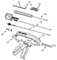
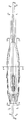
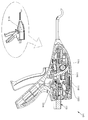
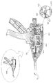
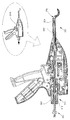
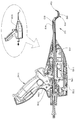
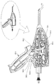
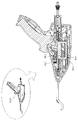
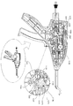
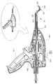
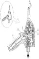
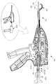
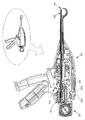
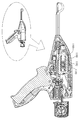
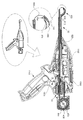
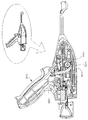
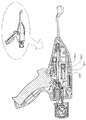
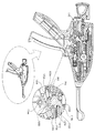
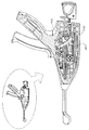
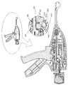
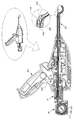
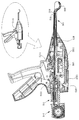
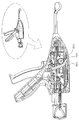
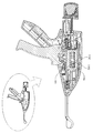
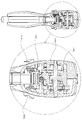
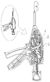
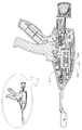
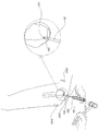
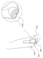
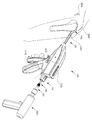
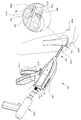
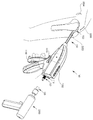
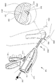
Figures 1A and 1B are simplified schematic illustrations of an arthroscopic surgical assembly constructed and operative in accordance with a preferred embodiment of the present invention, showing opposite views.
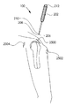
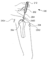
Figures 2a and 2b are simplified illustrations of a punch assembly forming part of the arthroscopic surgical assembly of Figures 1a and 1b.
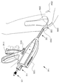
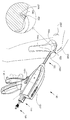
Figures 3a and 3b are simplified illustrations of a working channel assembly that forms part of the arthroscopic surgical assembly of Figures 1a and 1b.
Figures 3c, 3d, 3e, and 3f illustrate a forward view of the working channel hub, each forming part of the working channel assembly of Figures 3a and 3b; A rear view, a side view, and a frontward rear view are examples.
Figures 3g, 3h, 3i and 3j are schematic front views of a rack-defining intermediate element, each forming part of the working channel assembly of Figures 3a and 3b; A rear view, a side view, and a frontward rear view are examples.
Figures 3k, 3l, 3m, 3n, 3o and 3p illustrate a forward view of the retaining cap element, each forming part of the working channel assembly of Figures 3a and 3b; A top view of the rear, a bottom view of the rear, a rear view of the front, and first and second interior views.
Figures 4A, 4B, 4C and 4D are simplified illustrations of fast coupling elements forming part of the arthroscopic surgical assembly of Figures 1A and 1B.
Figures 5A and 5B are simplified illustrations of a drill bit assembly forming part of the arthroscopic surgical assembly of Figures 1A and 1B.
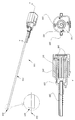
Figures 6a, 6b, 6c, and 6d illustrate simplified simplified backward and forward looking schematic views of a snare wire cartridge assembly, forming part of the arthroscopic surgical assembly of Figures 1a and 1b, and Examples of decomposition toward the rear and decomposition toward the front are examples.
Figs. 6e, 6f, 6g, and 6h are simplified individual interior plan views, first and second interior views, and rearward section views of the main housing portion of the snare wire cartridge assembly.
Figures 6i, 6j, 6k, and 61 l illustrate simplified simplified interior plan views, first and second internal views, and rearward section views of the secondary housing portion of the snare wire cartridge assembly.
6M, 6N, 6O, and 6P are simplified, separate top, first, second, and edge drawing illustrations of a snare-wire take-up drum forming part of a snare wire cartridge assembly.
Figures 6q and 6r are simplified first and second internal schematic illustrations of a tension element that cooperate with the snare-wire take-up drum.
6S is an illustration of a simplified side view of the snare wire cartridge assembly.
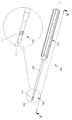
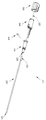
7A, 7B, 7C, 7D, 7E, 7F, 7G, 7H, 7I, 7J, 7K, 7L, 7M, 7N, 7O, Figures 1a and 1b are simplified illustrations of a curved shaft assembly forming part of the arthroscopic surgical assembly.
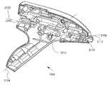
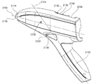
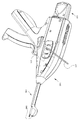
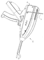
8A, 8B, 8C, 8D, 8E, 8F, 8G, 8H, 8I, 8J, 8K, 8L, 8M, 8N, 8O, 8P, 8Q 8a, 8a, 8a, 8a, 8a, 8b, 8c, 8y, 8z, 8aa, 8ab, 8ac, 8a, 8a, 8a, 8a, 8a, 8a, 8an, 8a, 8a, 8a, 8ar, 8as, 8at, 8au, 8av, 8aw, 8ax, 8b, 8b, 8b, 8b, 8b, 8b, 8b, 8b, 8b, 8b, 8b, 8b, 8b, 8b, 8b, 8b, 8b, 8bp, 8bq, 8br, 8bs, 8bt and 8bu are simplified illustrations of the arthroscopic device forming part of the arthroscopic surgical assembly of FIGS. 1a and 1b.
Figs. 9A, 9B and 9C are simplified top, side and bottom views of a manual override element useful in the operation of the arthroscopic surgery assemblies of Figs. 1A and 1B.
9D, 9E and 9F are simplified illustrations of the individual applications of manual override in the operation of the arthroscopic surgery assemblies of FIGS. 1A and 1B.
10a, 10b, 10c, 10d, 10e, 10f, 10g, 10h, 10i, 10j, 10k, 10l, 10m, 10n, 10o, 10p, 10q 10, 10, 10, 10, 10, 10v, 10w, 10x, 10y, 10z, 10aa, 10ab, 10ac, 10ad, 10ae, 10af, 10ag, 10ah, 10ai, 10aj, 10ak, 10al, 10am, and 10an are simplified illustrations of the details of the operation of the arthroscopic surgery assembly of FIGS. 1a-9f.
11a, 11b, 11c, 11d, 11e, 11f, 11g, 11h, 11i, 11j, 11k, 11l, 11m, 11n, 11o, 11p, 11q , Figures 11r, 11s and 11t are simplified illustrations of the operation of the arthroscopic device of Figures 1a-10an in a clinical context.
용어들 '터널' 및 '채널'이 본 발명의 설명에서 상호교환적으로 사용되며 이들이 뼈에 형성된 원통형의 원형 중공 구멍과 같은 중공 구멍을 지칭한다는 것이 이해될 것이다. 용어들 '터널링' 및 '채널링'이 본 발명의 설명에서 상호교환적으로 사용되며 이들이 뼈에 원통형의 원형 중공 구멍과 같은 중공 구멍을 형성하는 방법을 지칭한다는 것이 또한 이해될 것이다.It will be appreciated that the terms " tunnel " and " channel " are used interchangeably in the description of the present invention and refer to hollow holes such as cylindrical circular hollow holes formed in the bone. It will also be appreciated that the terms " tunneling " and " channeling " are used interchangeably in the description of the present invention and refer to a method in which they form a hollow hole, such as a cylindrical circular hole, in the bone.
본 발명의 설명 전체에 걸쳐 사용되는 용어 "봉합사"는 임의의 적절한 봉합사를 지칭하며, 또한 뼈를 통해 봉합사를 당기기 위해 사용되는 전달 와이어를 지칭한다는 것, 및 본 발명의 설명 전체에 걸쳐 사용되는 용어 "스네어 와이어"의 사용이 전달 와이어 또는 봉합사 중 하나를 지칭한다는 것이 추가로 이해될 것이다. 전형적으로, 스네어 와이어는 본 발명의 시스템 및 방법과 함께 사용되며, 니티놀로 형성된다. 전형적으로, 본 발명의 시스템 및 방법과 함께 사용되는 스네어 와이어는 일 단부에 루프를 형성하기 위하여 접힌다(folded over).The term "suture" used throughout the description of the present invention refers to any suitable suture, and also refers to a delivery wire used to pull the suture through the bone, and the terms used throughout the description of the present invention It will be further understood that the use of a "snare wire" refers to either a delivery wire or a suture. Typically, snare wires are used with the systems and methods of the present invention and are formed of Nitinol. Typically, the snare wire used with the system and method of the present invention is folded over to form a loop at one end.
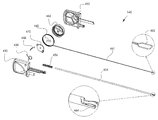
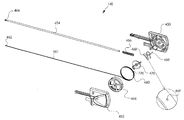
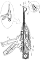
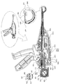
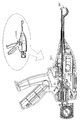
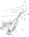
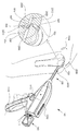
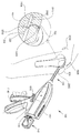
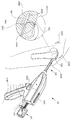
이제, 대향되는 도면들을 도시하는 본 발명의 선호되는 실시예에 따라 구성되고 동작하는 관절경 수술 어셈블리의 간략화된 도식적 예시들인 도 1a 및 도 1b와 이하에서 특히 언급되는 다양한 추가 도면들에 대한 참조가 이루어진다.Reference is now made to Figs. 1a and 1b, which are simplified schematic illustrations of arthroscopic surgery assemblies constructed and operative in accordance with the preferred embodiment of the present invention showing opposing views, and various further drawings referred to in particular below .
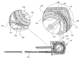
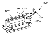
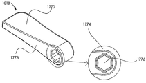
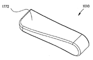
도 1a 및 도 1b에서 보여지는 바와 같이, 도 1a 및 도 1b의 관절경 수술 어셈블리는, 도 2a 및 도 2b에 도시된 뼈 펀치 어셈블리(100); 도 3a 및 도 3b에 도시된 작업 채널 어셈블리(110); 도 4a, 도 4b, 도 4c 및 도 4d에 도시된 빠른 연결 엘리먼트(120); 도 5a 및 도 5b에 도시된 드릴 비트 어셈블리(130); 도 6a 및 도 6b에 도시된 스네어 와이어 카트리지 어셈블리(140); 도 7a 및 도 7b에 도시된 만곡형 샤프트 어셈블리(150); 도 8a 및 도 8b에 도시된 관절경 수술 디바이스(160) 및 도 9a, 도 9b, 도 9c, 도 9d, 도 9e 및 도 9f에 도시되며 수동 오버라이드 기어 시프터(171) 및 2.5 mm 6각 렌치(172)를 포함하는 수동 오버라이드 엘리먼트들(170)을 포함한다.As shown in FIGS. 1A and 1B, the arthroscopic surgical assembly of FIGS. 1A and 1B includes a
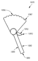
이제 도 2a 및 도 2b를 추가적으로 참조하면, 뼈 펀치 어셈블리(100)가 도시되며, 이는 바람직하게는, 전형적으로 플라스틱으로 형성되며 바람직하게는 130mm 길이인 핸들 부분(202), 전형적으로 강철로 형성되며 바람직하게는 85mm 길이인 중간 부분(204), 및 전형적으로 또한 강철로 형성되고 바람직하게는 20mm 길이이며 뾰족한 팁(208)을 갖는 전방 부분(206)을 포함한다. 바람직하게는 펀치를 사용하는 외과의에게 뼈 침투의 희망되는 정도를 나타내기 위하여 원주 마킹(circumferential marking)(210)이 전방 부분(206) 상에 형성된다. 예시된 실시예에 있어서, 표지 "8"은, 원주 마킹이 뾰족한 팁(208)의 포인트로부터 8 mm에 존재한다는 것을 나타낸다. 전반적으로 볼록한 충돌 표면(212)은 바람직하게는 수술 해머에 의한 충돌을 위하여 펀치(100)의 후방 단부 상에 형성된다.2A and 2B, a
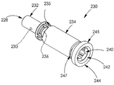
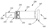
이제, 도 3a, 도 3b, 도 3c, 도 3d, 도 3e, 도 3f, 도 3g, 도 3h, 도 3i, 도 3j, 도 3k, 도 3l, 도 3m, 도 3n, 도 3o, 및 도 3p에 대한 참조가 이루어지며, 이들은 도 1a 및 도 1b의 관절경 수술 어셈블리의 부분을 형성하는 작업 채널 어셈블리(110)의 간략화된 예시들이다. 도 3a 내지 도 3p에서 보여지는 바와 같이, 작업 채널 어셈블리(110)는 바람직하게는, 전형적으로 스테인리스 강철로 형성되며 바람직하게는 3.2 mm의 외부 직경 및 2.7 mm의 내부 직경 그리고 길이 방향 축(222)을 따라 연장하는 대략 231 mm의 총 길이를 갖는 중공 세장형 튜브(220)를 포함한다. 바람직하게는, 세장형 튜브(220)의 전면 에지(224)는 축(222)에 대하여 100 도만큼 경사진다.3C, 3D, 3E, 3F, 3G, 3H, 3I, 3J, 3K, 3L, 3M, 3N, 3O, and 3P Which are simplified illustrations of a working
세장형 튜브(220)의 후방 단부(226)는 작업 채널 허브(230) 내에 형성된 소켓(228) 내에 고정적으로 장착된다. 작업 채널 허브(230)는 도 3c, 도 3d, 도 3e 및 도 3f에 도시되며, 이들은 각기 도 3a 및 도 3b의 작업 채널 어셈블리의 부분을 형성하는, 작업 채널 허브의 전방을 향한 도식적 예시; 후방을 향한 도식적 예시, 측면도 예시 및 전방을 향한 후방 단면도 예시이다.The
도 3c 내지 도 3f에서 보여지는 바와 같이, 작업 채널 허브(230)는, 횡방향 구멍(233)을 갖는 전방 소켓-획정 부분(232)을 갖는 전반적으로 원형의 원통형으로 일체로 형성된 엘리먼트이다. 전방 소켓-획정 부분(232)의 후방에는, 전방 환형 표면(235)을 가지며 바람직하게는 그것의 전방 단부에 형성된 복수의, 바람직하게는 4개의 방위각적으로(azimuthally)-분포된 컷 아웃(cut out)들(236)을 갖는 메인 원통형 부분(234)이 존재한다. 메인 원통형 부분(234)은 바람직하게는, 꽃-모양의 단면 구성을 가지며 그리고 바람직하게는 6각형으로 홈이 파인(chamfered) 중간 입구(entry) 부분(240) 및 허브(230)의 후방 단부(244)에 인접한 원형으로 홈이 파인 후방 입구 부분(242)을 갖는 축 방향 중심 구멍(238)을 갖도록 형성된다. 플랜지(245)가 허브(230)의 후방 단부(244)에 제공되며, 전방을 향한 원주방향(circumferential) 플랜지 표면(246)을 획정한다.3C-3F, the working
메인 원통형 부분(234)은 바람직하게는, 유지 클립 엘리먼트(248)(도 3b)를 착탈가능하게 수용하는 부분적인 원주방향 슬롯(247)을 가지고 그것의 후방 단부(244)에 인접하여 형성된다. 슬롯(247)은 축 방향 중심 구멍(238)과 연통하여, 삽입될 때 클립 엘리먼트(248)가 그 안의 2개의 방위각적 위치들에서 축 방향 중심 구멍(238)을 횡단한다.The main
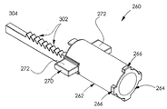
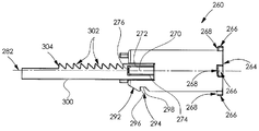
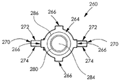
작업 채널 허브(230)는 랙-획정 중간 엘리먼트(260) 내에 부분적으로 안착된다. 각기, 도 3a 및 도 3b의 작업 채널 어셈블리(110)의 부분을 형성하는, 랙-획정 중간 엘리먼트(260)의 전방을 향한 도식적 예시; 후방을 향한 도식적 예시, 측면도 예시 및 전방을 향한 후방 단면도 예시인 도 3g, 도 3h, 도 3i 및 도 3j에 랙-획정 중간 엘리먼트(260)가 예시된다.The working
도 3g 내지 도 3j에서 보여지는 바와 같이, 랙-획정 중간 엘리먼트(260)는, 각각이 홈이 파인 전방을 향한 표면(268)을 갖는 4개의 방위각적으로 분포되고 방사상으로 연장하는 돌출부들(266)을 갖는 후방 표면(264)을 갖는 메인 원통형 부분(262)을 포함한다. 각각의 전방을 향한 표면(276)에 의해 결합되는 상부 표면(272) 및 하부 표면(274)을 갖는 날개-모양의 돌출부들(270)이 메인 원통형 부분(262)으로부터 대향되는 방향으로 방사상으로 바깥쪽으로 연장한다.3G-3J, the rack-defining
메인 원통형 부분(262)은 축 방향 구멍(280)을 갖도록 형성되며, 이는 축(282)을 따라 연장하고 홈이 파인 후방을 향한 에지(286)를 갖는 어느 정도 좁아진 전방 구멍 개구(284)를 갖는다. 메인 원통형 부분(262)의 전방 단부(290)에는 횡방향의 각이 진 평평한 부분(292)이 제공되며, 이의 후방에는, 후방을 향한 표면(296) 및 전반적으로 직각으로 표면(296)과 결합하는 횡방향 표면(298)을 갖는 횡방향 언더컷(undercut)(294)이 형성된다.The main
전반적으로 직사각형 단면의 샤프트(300)가 메인 원통형 부분(262)의 전방 단부(290)로부터 전방으로 연장하며, 이는 선형 래칫 기어 랙(304)을 획정하는 래칫 티쓰(302)의 로우(row)을 갖도록 형성된다.A generally
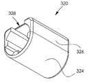
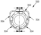
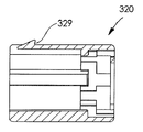
이제, 각기, 도 3a 및 도 3b의 작업 채널 어셈블리의 부분을 형성하는, 유지 캡 엘리먼트(320)의 전방을 향한 도식적 예시; 상단의 후방을 향한 도식적 예시, 하단의 후방을 향한 도식적 예시, 후방을 향한 전방 단면도 예시, 및 제 1 및 제 2 내부 측면도 예시들인 도 3k, 도 3l, 도 3m, 도 3n, 도 3o 및 도 3p에 대한 참조가 이루어진다.A schematic front view of the retaining
도 3k 내지 도 3p에서 보여지는 바와 같이, 유지 캡 엘리먼트(320)는, 전반적으로 평평한 상단 표면(322), 만곡되고 결합된 하단 및 하부 측면 표면(324) 및 전반적으로 평평한 측면 표면들(326)을 갖는 전반적으로 원통형 엘리먼트이다. 후방을 향한 유지 표면(329)을 갖는 언더컷 후크형(hooked) 맞물림 핑거(finger)(328)가 상단 표면(322) 상에 제공된다. 후방 표면(330)은, 랙-획정 중간 엘리먼트(260)의 돌출부를 잠금식으로 수용하도록 구성된 복수의 개구부들(332)을 갖도록 형성된다.3K-3P, the retaining
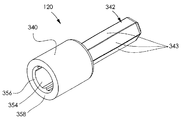
이제, 각기, 도 1a 및 도 1b의 관절경 수술 어셈블리의 부분을 형성하는, 전형적으로 플라스틱으로 형성되며 바람직하게는 56 mm 길이인 빠른 연결 엘리먼트(120)의 간략화된 전방을 향한 도식적 예시, 후방을 향한 도식적 예시, 측면도 예시 및 전방을 향한 후방 단면 예시인 도 4a, 도 4b, 도 4c 및 도 4d에 대한 참조가 이루어진다.Now, a simplified frontward schematic illustration of a
도 4a 내지 도 4d에서 보여지는 바와 같이, 빠른 연결 엘리먼트(120)는, 바람직하게는 35 mm 길이의 전방의 전반적으로 원형의 원통형 부분(340), 및 6개의 세장형의 평평한 표면들(343)을 갖는 바람직하게는 21 mm 길이 및 6 mm 직경을 갖는 후방의 6각형의 원통형 연장부(342)를 포함한다. 원형의 원통형 섹션(340)의 후방에는 테이퍼진(tapered) 섹션(344)이 존재하며, 이는 후방을 향한 평평한 표면(346)까지 아래로 테이퍼진다. 6각형 연장부(342)의 평평한 표면들(343)을 결합하는 복수의 테이퍼진 6각형 부분들(348)이 후방을 향한 평평한 표면(346)으로부터 연장한다.4A-4D, the
6각형 연장부(342)의 후방에는, 테이퍼진 표면들(352)에 의해 세장형의 평평한 표면(343)에 결합되는 6각형 형상의 후방을 향한 평평한 표면(350)이 존재한다.Behind the
원통형 부분(340)의 내부는 바람직하게는, 빠른 연결 엘리먼트(120)의 후방 단부(358)에 인접하여 꽃-모양의 단면 구성을 가지며 그리고 바람직하게는 6각형으로 홈이 파인 중간 입구 부분(356)을 갖는 축 방향 중심 구멍(354)을 갖도록 형성된다. 이러한 구멍은, 도 5a 및 도 5b에 도시되며 이하에서 설명되는 바와 같은 드릴 비트 어셈블리의 샤프트 부분(420)과 맞물리기 위한 소켓으로서 역할한다.The interior of the
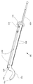
이제 도 5a 및 도 5b에 대한 참조가 이루어지며, 이들은 도 1a 및 도 1b의 관절경 수술 어셈블리의 부분을 형성하는 드릴 비트 어셈블리(130)의 간략화된 예시들이다. 도 5a 및 도 5b에서 보여지는 바와 같이, 드릴 비트 어셈블리(130)는, 전형적으로 강철로 형성되며 바람직하게는 약 289 mm의 총 길이를 가지고, 그것의 전방 단부에 형성된 전형적으로 12 mm 길이의 날카롭게 갈린 나선형 드릴 팁(402)을 갖는 세장형 샤프트 부분(400)을 포함한다. 바람직하게는, 샤프트 부분(400)의 후방 부분(404) 위에 바람직하게는 플라스틱으로 형성되며 32.1 mm 길이의 맞물림 부분(406)이 오버몰딩(overmold)된다.Reference is now made to Figs. 5A and 5B, which are simplified illustrations of a
맞물림 부분(406)은 바람직하게는 평평한 후방을 향한 환형 표면(408)을 포함한다. 테이퍼진 골이 있는(ribbed) 그래스핑(grasping) 부분(410)이 평평한 후방을 향한 환형 표면(408)의 전방에 존재한다. 작업 채널 허브(230)의 축 방향 중심 구멍(238)과 구동 맞물림을 위하여 구성된 6각형 외부 단면을 갖는 바람직하게는 세장형 작업 채널 구동 샤프트 부분(412)이 테이퍼진 골이 있는 그래스핑 부분(410)의 전방에 존재한다. 클립 엘리먼트(248)(도 3b)를 수용하기 위하여 얕은 원주방향 리세스(recess)(414)가 작업 채널 구동 샤프트 부분(412)에 형성되며, 이는 그 사이의 상대적인 길이 방향 변위에 대하여 작업 채널 구동 샤프트 부분(412)을 작업 채널 허브(230)의 축 방향 중심 구멍(238) 내에 유지한다. 세장형 작업 채널 구동 샤프트 부분(412)은 전방으로 테이퍼진 전방 면(416)에서 끝나며, 이는 허브(230)의 후방 단부(244)에 인접한 6각형 홈이 파인 중간 입구 부분(240)의 원형으로 홈이 파인 후방 입구 부분(242)과 맞물린다.The
6각형 외부 단면 및 홈이 파인 단부 면(422)을 갖는 샤프트 부분(420)이 평평한 후방을 향한 환형 표면(408)의 후방에 존재한다. 샤프트 부분(420)은 이에 의해 구동되기 위한 빠른 연결 엘리먼트(120)의 구멍(354)과 맞물린다.A
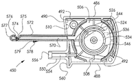
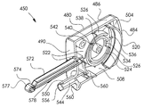
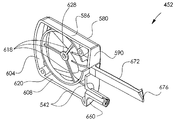
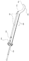
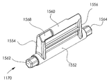
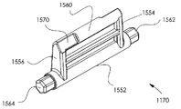
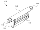
이제, 도 1a 및 도 1b의 관절경 수술 어셈블리의 부분을 형성하는, 스네어 와이어 카트리지 어셈블리(140)의 간략화된 개별적인 후방을 향한 도식적 예시 및 전방을 향한 도식적 예시, 및 후방을 향한 분해도 예시 및 전방을 향한 분해도 예시인 도 6a, 도 6b, 도 6c 및 도 6d에 대하여; 스네어 와이어 카트리지 어셈블리의 메인 하우징 부분의 간략화된 개별적인 내부 평면도, 제 1 및 제 2 내부 도식도 및 후방을 향한 단면도 예시들인 도 6e, 도 6f, 도 6g 및 도 6h에 대하여; 스네어 와이어 카트리지 어셈블리의 2차 하우징 부분의 간략화된 개별적인 내부 평면도, 제 1 및 제 2 내부 도식도 및 후방을 향한 단면도 예시들인 도 6i, 도 6j, 도 6k 및 도 6l에 대하여; 스네어 와이어 카트리지 어셈블리의 부분을 형성하는 스네어 와이어 권취 드럼의 간략화된 개별적인 평면도, 제 1 및 제 2 도식도 및 에지 도면 예시들인 도 6m, 도 6n, 도 6o 및 도 6p에 대하여; 스네어 와이어 권취 드럼과 함께 동작하는 인장 엘리먼트의 간략화된 제 1 및 제 2 내부 도식도 예시들인 도 6q 및 도 6r에 대하여; 도 6b에서 라인 S-S를 따라 취한 간략화된 섹션 예시인 도 6s에 대한 참조가 이루어진다.A simplified simplified rearward and schematic illustration of a snare
이제, 바람직하게는 313.5 mm의 총 길이를 갖는 스네어 와이어 카트리지 어셈블리(140)의 간략화된 개별적인 후방을 향한 도식적 예시 및 전방을 향한 도식적 예시, 및 후방을 향한 분해도 예시 및 전방을 향한 분해도 예시인 도 6a, 도 6b, 도 6c 및 도 6d를 참조하면, 스네어 와이어 카트리지 어셈블리(140)는 바람직하게는 메인 하우징 부분(45)과 2차 하우징 부분(452), 및 메인 및 2차 하우징 부분들(450 및 452) 상에 장착되는, 개구(455)를 가지며 바람직하게는 스테인리스 강철로 형성되고 메인 및 2 차 하우징 부분들(450 및 452)로부터 외부로 255.8 mm 연장하는 세장형 중공 샤프트(454)를 포함한다는 것이 확인된다.6A, which is a simplified simplified rearward and schematic illustration of a snare
메인 하우징 부분(450)은 도 6e, 도 6f, 도 6g 및 도 6h를 참조하여 이하에서 상세하게 설명되며, 2차 하우징 부분(452)은 도 6i, 도 6j, 도 6k 및 도 6i를 참조하여 이하에서 상세하게 설명된다.The
이하에서 설명되는 바와 같이, 압축 스프링(456)은 그것의 후방 단부에 인접하여 샤프트(454) 위에 장착되며, 인장 스프링(458)은 메인 하우징 부분(450) 내에 장착된다.
미리-형성된 루프(462)를 또한 획정하는 스네어 와이어(461)의 접힌 길이(460)는 부분적으로 중공 샤프트(454) 내에 위치되어, 루프(462)는 그것의 세장형 중공 샤프트(454)의 전방 단부(464)에 장착되고 메인 하우징 부분(450) 내에 위치된 스네어 와이어 권취 드럼(466) 둘레에 부분적으로 감기며 와이어 통과 개구(469)를 갖는 탄성 유지 엘리먼트(468)에 의해 그 위에 유지된다. 드럼은 도 6m 내지 도 6p를 참조하여 이하에서 상세하게 설명된다. 스네어 와이어(461)의 희망되는 인장은 스네어 와이어 권취 드럼(466)과 함께 동작하는 인장 엘리먼트(470)에 의해 제공된다. 인장 엘리먼트(470)는 이하에서 도 6q 및 도 6r을 참조하여 상세하게 설명된다.The folded
이제 메인 하우징 부분(450)을 예시하는 도 6e, 도 6f, 도 6g 및 도 6h에 대하여 추적인 참조가 이루어진다. 도 6a 내지 도 6d 및 도 6e 내지 도 6g에서 보여지는 바와 같이, 메인 하우징 부분(450)은, 핑거 맞물림 디텐트(detent)(482), 만곡된 후방을 향한 에지(484), 개별적인 상단 및 하단 에지들(486 및 488) 및 전방을 향한 에지(490)를 갖는 전반적으로 직사각형의 외부 표면(480)을 포함한다.Reference is now made to FIG. 6E, FIG. 6F, FIG. 6G and FIG. 6H which now illustrate the
메인 하우징 부분(450)의 내부는 원주방향 벽 표면(492)에 의해 경계가 지어지며, 이는 만곡된 후방을 향한 에지(484)에 대응하는 후방 벽 표면(504), 개별적인 상단 및 하단 에지들(486 및 488)에 대응하는 개별적인 상단 및 하단 벽 표면들(506 및 508), 및 전방을 향한 에지(490)에 대응하는 전방 벽 표면(510)을 포함한다.The interior of the
전반적으로 원형의 후방 내부 벽(520)이 후방 벽 표면(504)에 인접하여 위치되며, 전반적으로 원형의 전방 내부 벽(522)이 전방 벽 표면(510)에 인접하여 위치된다. 개별적인 개구부들(534 및 536)을 획정하는 내부 및 외부의 전반적으로 원형의 상호 포개진 벽들(524 및 526)이 중심 돌기(boss)(538)를 둘러싼다. 상호 정렬된 각이 진 슬릿들(540 및 542)이 개별적인 벽들(524 및 526) 내에 형성된다. 벽(526) 내의 개구부(536)가 접합부들(544 및 546)을 획정한다.A generally circular rear
압축 스프링(456)에 대한 후방 스프링 시트(seat)를 획정하는 넓어진 전방을 향한 리세스(556) 및 샤프트(454)의 후방 단부를 수용하기 위한 구멍(554)을 갖는 샤프트 장착 소켓 획정 중공 돌출부(550)가 전방을 향한 에지(490)로부터 전방으로 연장한다. 돌출부(550)는 벽(560) 아래에 그리고 이의 후방에 위치된다.A shaft-mounted socket defining hollow protrusion (not shown) having an enlarged forward facing
또한 카트리지 어셈블리 유지 샤프트 부분(572)이 전반적으로 원형의 전방 내부 벽(522)에 형성된 개구부(570)에서 전방을 향한 에지(490)로부터 전방으로 연장한다. 샤프트(572)는 경사진 전방을 향한 표면(575) 및 경사진 후방을 향한 표면(576)을 갖는 상단을 향한 노치(notch)(574)를 갖는다. 노치(574)는 그것의 원형 전방 단부(577) 및 샤프트(572)의 하단을 향한 표면 상에 노치(574)의 후방에 형성된 유지 표면(579)을 획정하는 하단을 향한 투쓰(tooth)(578)에 인접하여 형성된다.The cartridge assembly
이제 2차 하우징 부분(452)을 예시하는 도 6i, 도 6j, 도 6k 및 도 6l에 대하여 추가적인 참조가 이루어진다. 도 6a 내지 도 6d 및 도 6i 내지 도 6l에서 보여지는 바와 같이, 2차 하우징 부분(452)은, 핑거 맞물림 디텐트(582), 만곡된 후방을 향한 에지(584), 개별적인 상단 및 하단 에지들(586 및 588) 및 전방을 향한 에지(590)를 갖는 전반적으로 직사각형의 외부 표면(580)을 포함한다.Additional reference is now made to Figs. 6i, 6j, 6k and 61l illustrating the
2차 하우징 부분(452)의 내부는 원주방향 벽 표면(592)에 의해 경계가 지어지며, 이는 만곡된 후방을 향한 에지(584)에 대응하는 후방 벽 표면(604), 개별적인 상단 및 하단 에지들(586 및 588)에 대응하는 개별적인 상단 및 하단 벽 표면들(606 및 608), 및 전방을 향한 에지(590)에 대응하는 전방 벽 표면(610)을 포함한다.The interior of the
3개의 방사상으로 연장하는 돌출부들(618)이 전반적으로 원형의 내부 벽(620)을 중심 돌기(628)에 연결한다.Three radially extending
스프링 유지 돌출부들(658)을 갖는, 압축 스프링(456)에 대한 후방 스프링 시트(seat)를 획정하는 넓어진 전방을 향한 리세스(656) 및 샤프트(454)의 후방 단부를 수용하기 위한 구멍(654)을 갖는 샤프트 장착 소켓 획정 중공 돌출부(650)가 전방을 향한 에지(590)로부터 전방으로 연장한다. 돌출부(650)는 벽(660) 아래에 그리고 이의 후방에 위치된다.An enlarged forwardly facing
또한 카트리지 어셈블리 유지 샤프트 부분(672)이 전반적으로 원형의 전방 내부 벽(620)에 형성된 개구부(670)를 통해 전방을 향한 에지(590)로부터 전방 및 후방으로 연장한다. 샤프트 부분(672)은 인접한 경사진 표면들(676 및 678)을 획정하는 이중으로 테이퍼진 전면 단부(674)를 갖는다. 표면(676)은 바람직하게는 상단을 향한 노치(574)를 갖는 샤프트(572)의 표면(575)와 동일 평면이다. 도 6b 및 도 6l에서 구체적으로 보여지는 바와 같이, 샤프트 부분(672)은 바람직하게는 그것의 수동 맞물림을 위한 보조개(dimple) 모양의 돌출부(680)를 갖도록 형성된다. 샤프트 부분(672)은 2차 하우징 부분(452)에 대하여 캔틸레버(cantilever)되어, 보조개 모양의 돌출부(680)가 사용자에 의해 눌려질 때, 샤프트 부분(672)이 카트리지 어셈블리 유지 샤프트 부분(572)에 더 가깝게 이동되며, 그에 따라서 관절경 수술 디바이스(160)와의 스냅-핏(snap-fit) 맞물림으로부터 카트리지 어셈블리(140)를 릴리즈한다는 것이 이해될 것이다.The cartridge assembly
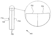
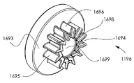
이제 도 6m, 도 6n, 도 6o 및 도 6p에 대한 추가적인 참조가 이루어지며, 이러한 도면들은 스네어 와이어 카트리지 어셈블리의 부분을 형성하는 스네어 와이어 권취 드럼(466)의 간략화된 개별적인 평면도, 제 1 및 제 2 도식도 및 에지 도면 예시들이다.Additional references to Figures 6m, 6n, 6o and 6p are now made, which illustrate simplified individual plan views of the snare-wire take-
도 6m 내지 도 6p에서 보여지는 바와 같이, 스네어 와이어 권취 드럼(466)은 전반적으로 원형의 대칭적인 엘리먼트로서, 이는 바람직하게는 플라스틱으로 사출-몰딩(injection-mold)되며, 그 사이에 최소 반경의 링을 획정하기 위하여 상호 경사진 2개의 상호 경사진 에지 부분들(702 및 704)에 의해 획정되는 원주방향 외부 에지 부분(700)을 갖는다. 횡방향 슬롯(706)은 에지 부분(704)의 에지에서 개구부(707)를 가지며, 이에 걸쳐서 그리고 에지 부분(702) 내로 연장한다.As shown in Figures 6m-6p, the snare-
원주방향 외부 에지 부분(700)은, 중심 영역(716)에서 결합되는 크로스 피스들(714)의 쌍 및 환형 링 부분(712)을 갖는 전반적으로 평평한 베이스 부분(710)과 일체로 형성된다. 중공 액슬(718)은 축(720)을 따라서 전반적으로 평평한 베이스 부분(710)에 수직으로 연장한다. 중공 액슬(718)은 이와 동축인 짧은 부분(722) 및 더 긴 부분(724)을 포함한다.Circumferential
축(720)이 대칭적인 축이며 스네어 와이어 권취 드럼(466)의 회전 축이라는 것이 이해될 것이다. 경사진 에지 부분(702)의 에지 영역(726)이 전반적으로 평평한 베이스 부분(710)을 넘어 연장한다는 것이 또한 보여진다.It will be appreciated that the
내부를 향한 원형 표면(732)을 갖는 내부 링 부분(730)이 외부 에지 부분(700)의 내부에 배치되며 액슬(718)의 더 긴 부분(724)에 대하여 원형의 대칭적인 배열로 연장한다. 전반적으로 평평한 베이스 부분(710)에 인접한 내부를 향한 원형 표면(732)의 원형의 대칭적인 부분은 기어 티쓰의 원형의 대칭적인 어레이(734)를 갖도록 형성된다. 립(rib)(736)은 내부 링 부분(730)의 방사상으로 바깥쪽을 향한 표면으로부터 전반적으로 방사상으로 바깥쪽으로 연장하며 외부 에지 부분(700)의 방사상으로 안쪽을 향한 표면과 결합한다.An
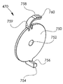
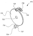
이제 도 6q 및 도 6r에 대한 추가적인 참조가 이루어지며, 이러한 도면들은 스네어 와이어 권취 드럼(466)과 함께 동작하는 인장 엘리먼트(470)의 간략화된 제 1 및 제 2 내부 도식도 예시들이다. 인장 엘리먼트(470)는 바람직하게는 중심 개구(752)를 갖는 디스크 부분(750) 및 디스크 부분(750)의 일 측으로부터 및 일 측으로 방사상으로 바깥쪽으로 연장하는 스프링 맞물림 돌출부(754)를 포함한다. 스프링 맞물림 돌출부(754)는 경사진 스프링 맞물림 표면(756) 및 접합부 맞물림 표면(757)을 획정한다.Additional references to Figs. 6q and 6r are now made, which illustrate simplified first and second internal schematics of the
방사상으로 바깥쪽으로 연장하는 가요성 래칫 기어 맞물림 부분(758)이 스프링 맞물림 돌출부(754)에 전반적으로 대향되는 방향으로 디스크 부분(75)으로부터 방사상으로 바깥쪽으로 연장하며 그런 다음 디스크 부분(750)에 형성된 리세스(759)로부터 원주방향으로 연장한다. 가요성 래칫 기어 맞물림 부분(758)은 그것의 원주방향 외측 부분에, 스네어 와이어 권취 드럼(466)의 기이 티스의 원형의 대칭적인 어레이(734)와의 래칫-형 맞물림을 위하여 구성된 기어 티쓰의 만곡된 선형 어레이(760)를 포함한다.A radially outwardly extending flexible ratchet
이제, 스네어 와이어 카트리지 어셈블리(140)의 간략화된 측면도 예시인 도 6s에 대한 추가적인 참조가 이루어진다. 도 6s에서 보여지는 바와 같이, 스네어 와이어(461)의 단부 부분(770)은 패드(468) 내의 개구(469)를 통해 삽입되어, 결과적으로 립(736)에 인접한 원주방향 외부 에지 부분(700)의 방사상으로 내부를 향한 표면과 내부 링 부분(730)의 방사상으로 외부를 향한 표면 사이에 위치된다.Additional reference is now made to Fig. 6S, which is an illustration of a simplified side view of snare
스네어 와이어(461)은 슬롯(706)을 통해 단부 부분(770)으로부터 연장하며, 스네어 와이어 권취 드럼(466)의 원주방향 외부 에지 부분(700)의 외부 표면 둘레에 감기고 세장형 중공 샤프트(454)를 통해 연장한다.The
가요성 래칫 기어 맞물림 부분(758)의 만곡된 선형 어레이(760)가 스네어 와이어 권취 드럼(466) 상의 기어 티쓰의 만곡된 선형 어레이(734)와 맞물려서, 인장 엘리먼트(470)의 반시계 방향 회전이 도 6s의 의미에서 스네어 와이어 권취 드럼(466)의 대응하는 반시계 방향 회전을 생성한다는 것이 보여진다. 따라서, 스프링 맞물림 돌출부(754)의 접합부 맞물림 표면(757)과 스프링(458)의 맞물림이 도 6s의 의미에서 인장 엘리먼트(470) 및 스네어 와이어 권취 드럼(466) 둘 모두의 반시계 방향 회전을 강제하여 스네어 와이어(461)를 인장한다는 것이 이해될 것이다.The curved
이하에서 설명될 바와 같이, 장력 하에서 스네어 와이어 권취 드럼(466) 상에 감긴 스네어 와이어(461)를 당기는 것은, 스프링(458)의 강제에 대하여 도 6s의 의미에서 시계 방향으로 드럼(466)을 회전시킨다. 이러한 시계 방향 회전은, 드럼이 메인 하우징 부분(450)의 접합부(546)와 스프링 맞물림 돌출부(754)의 접합부 맞물림 표면(757)의 맞물림에 기인하여 더 이상 회전하지 않을 때까지 계속된다. 이러한 단계에서, 스네어 와이어(461) 상의 계속되는 당김은, 와이어가 탄성 유지 엘리먼트(468)로부터 분리되고 그런 다음 드럼(466)으로부터 자유롭게 풀려서 세장형 중공 샤프트(454)를 통해 전방으로 인출될 수 있게끔 한다.Pulling the
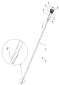
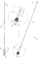
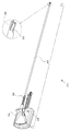
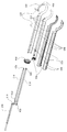
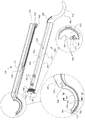
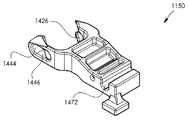
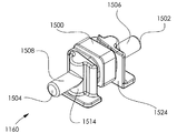
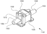
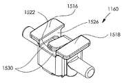
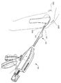
이제 도 7a, 도 7b, 도 7c, 도 7d, 도 7e, 도 7f, 도 7g, 도 7h, 도 7i, 도 7j, 도 7k, 도 7l, 도 7m, 도 7n, 도 7o, 도 7p에 대한 참조가 이루어지며, 이러한 도면들은 도 1a 및 도 1b의 관절경 수술 어셈블리의 부분을 형성하는 만곡형 샤프트 어셈블리(150)의 간략화된 예시들이다.7A, 7B, 7C, 7D, 7E, 7F, 7G, 7H, 7I, 7J, 7K, 7L, 7M, 7N, 7O, 7P, Reference is made to these drawings, which are simplified illustrations of a
도 7a 및 도 7b는 만곡형 샤프트 어셈블리(150)의 간략화된 개별적인 후방을 향한 그리고 전방을 향한 도식적 예시들이며, 도 7c 및 도 7d는 만곡형 샤프트 어셈블리(150)의 간략화된 개별적인 후방을 향한 그리고 전방을 향한 분해도 예시들이다. 도 7a 내지 도 7d에서 보여지는 바와 같이, 만곡형 샤프트 어셈블리(150)는 바람직하게는, 서로 바람직하게는 거울 이미지들이며, 금속으로 형성되고 정렬 핀들(801)에 의해 그리고 바람직하게는 또한 레이저 용접에 의해 결합되는 만곡형 샤프트 어셈블리 외부 엘리먼트들(800)의 쌍을 포함한다. 바람직하게는 서로 거울 이미지들이고 플라스틱으로 형성된 만곡형 샤프트 어셈블리 내부 엘리먼트들(802)의 쌍이 외부 구조적 엘리먼트들(800)의 내부에 배치된다. 정렬 핀들(801)은 엘리먼트들(800 및 802)에 형성된 대응하는 정렬된 개구들(803)을 통해 연장한다.Figures 7a and 7b are simplified simplified rearward and frontward illustrations of the
내부에 나사산이 형성된 만곡형 샤프트 어셈블리 위치결정 링(804)이 내부 엘리먼트들(802)의 대응하는 나사산이 형성된 단부들(806)에 나사결합으로 맞물리며, 관절경 수술 디바이스(160)의 하우징 내의 고정된 축 방향 위치에 유지된다. 링(804)과 내부 엘리먼트들(802) 사이의 나사결합 맞물림은 제조 동안 관절경 수술 디바이스(160)의 나머지 부분에 대한 만곡형 샤프트 어셈블리(150)의 위치의 축 방향 조정가능성을 제공한다는 것이 이해될 것이다.A curved shaft
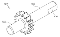
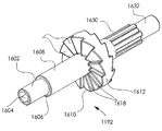
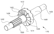
구부릴 수 있는 푸셔 스트립들(810 및 812)의 쌍이 내부 엘리먼트들(802)을 통해 연장하며, 바람직하게는, 도 7p의 확대도 C에서 구체적으로 보여지는 바와 같이, 세장형 푸시 막대(rod)(820)의 상단 돌출부(818)와의 구동 맞물림을 위한 푸시 막대 맞물림 개구들(814 및 816)을 갖도록 형성된다. 푸셔 스트립들(810 및 812)은 또한, 도 7p의 확대도 B에서 구체적으로 보여지는 바와 같이, 뼈 천자 바늘(840)의 상단 돌출부(830)와의 구동 맞물림을 위한 뼈 천자 바늘 맞물림 개구들(824 및 826)을 갖도록 형성된다.A pair of bendable pusher strips 810 and 812 extend through the
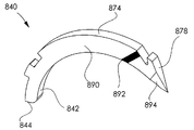
이제 도 7e, 도 7f 및 도 7g에 대한 참조가 또한 이루어지며, 이러한 도면들은 바람직하게는 스테인리스 강철로 형성되는 뼈 천자 바늘(840)을 예시한다. 뼈 천자 바늘(840)은 전반적으로 직사각형 단면을 갖는 전반적으로 만곡된 바늘이라는 것이 보여진다. 뼈 천자 바늘(840)은 바람직하게는, 도 7p의 확대도 A에서 구체적으로 보여지는 바와 같이, 약간 둥근 후방 단부 표면(844)으로부터 이것이 어느 정도 평평한 표면(868)을 갖는 테이퍼진 팁(866)까지 연장하는 방사상으로 안쪽을 향한 전반적으로 만곡된 에지 표면(842)을 갖도록 형성된다. 뼈 천자 바늘(840)은, 도 7p의 확대도 B에서 구체적으로 보여지는 바와 같이, 후방 단부 표면(844)에서의 전반적으로 비-원형 코너(870)로부터 상단 돌출부(830)(도 7c 및 도 7d)로 그리고 이를 넘어서 전방의 방사상으로 바깥쪽을 향한 전반적으로 만곡된 표면 부분(874)이 이로부터 연장하는 숄더(872)까지 연장하는, 후방의 방사상으로 바깥쪽을 향한 전반적으로 만곡된 표면 부분(869)을 갖도록 형성된다. 상단 돌출부(830)는, 개별적인 구부릴 수 있는 푸시 스트립들(810 및 812)에 의해 구동되기 위하여 개별적인 구부릴 수 있는 푸시 스트립들(810 및 812)의 푸시 막대 맞물림 개구들(824 및 826)과 맞물린다.Reference is now also made to Figs. 7e, 7f and 7g, which illustrate bone puncture needles 840, which are preferably formed of stainless steel. The
전방의 방사상으로 바깥쪽을 향한 전반적으로 만곡된 표면 부분(874)은, 도 7p의 확대도 A에서 구체적으로 보여지는 바와 같이, 후크를 획정하는 전방으로 그리고 방사상으로 안쪽을 경사진 노치(876)로, 그리고 이를 넘어서 전방의 전반적으로 평평한 테이퍼진 상단 팁 표면(878)으로 연장한다.The forwardly radially outwardly generally
뼈 천자 바늘(840)은, 서로 거울 이미지들이며 바람직하게는 적절하게 위치된 카메라를 사용하여 수술자에게 용이하게 보일 수 있는 마킹(892)을 포함하는 만곡된 측면 표면들(890)의 쌍을 포함한다. 만곡된 측면 표면들(890)은 각각 테이퍼진 팁 측면 표면(894)을 포함한다.Bone puncture needles 840 include pairs of curved
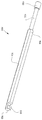
이제 세장형 푸시 막대(820)를 예시하는 도 7h 및 도 7i에 대한 참조가 이루어진다. 세장형 푸시 막대(820)는 바람직하게는 스테인리스 강철로 형성되며, 도 7p의 확대도 C 및 확대도 D에서 구체적으로 보여지는 바와 같이, 제 1 반경을 갖는 원통형 후방 부분(900), 제 1 반경보다 더 작은 제 2 반경을 갖는 중간 후방 부분(902), 및 제 1 반경과 동일한 전체 반경을 가지며 그것의 대향되는 측면들 상에 평평한 측면 표면들(906)을 갖는 메인 부분(904)을 포함한다. 세장형 푸시 막대(820)의 전방 단부(908)에는, 도 7p의 확대도 C에서 구체적으로 보여지는 바와 같이, 개별적인 구부릴 수 있는 푸셔 스트립들(810 및 812)의 푸시 막대 맞물림 개구들(814 및 816)과 구동이 가능하게(drivingly) 맞물리는 상단 돌출부(818)(도 7c 및 도 7d)가 형성된다.Reference is now made to Figs. 7h and 7i illustrating the
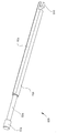
이제, 만곡형 샤프트 어셈블리 외부 엘리먼트들(800) 중 하나를 예시하는 도 7j 및 도 7k에 대한 참조가 이루어진다. 도 7j 및 도 7k에서 보여지는 바와 같이, 만곡형 샤프트 어셈블리 외부 엘리먼트들(800)의 각각은 상단 및 하단 만곡된 세장형 부분들(912 및 914) 각각 및 그 사이에서 연장하는 평평한 세장형 부분(916)을 갖는 세장형 메인 부분(910)을 포함한다. 도 7p의 확대도 D에서 구체적으로 보여지는 바와 같이, 개구들(918)의 쌍이 그것의 후방 단부(919)에 인접하여 평평한 세장형 부분 상에 형성된다.Reference is now made to Figs. 7J and 7K illustrating one of the curved shaft assembly
전반적으로 볼록한 단면을 갖는 만곡된 외부 표면(922) 및 전반적으로 오목한 단면을 갖는 만곡된 내부 표면(924)을 갖는 후크 부분(920)이 메인 부분(910)이 전방에 배치되며, 이들 둘 모두는 전방 에지(926)에서 끝난다.A
이제 만곡형 샤프트 어셈블리 내부 엘리먼트들(802) 중 하나를 예시하는 도 7l 및 도 7m에 대한 참조가 이루어진다. 도 7l 및 도 7m에서 보여지는 바와 같이, 만곡형 샤프트 어셈블리 내부 엘리먼트들(802)의 각각은 각기 상단 및 하단 만곡된 세장형 부분들(932 및 934) 및 그 사이에서 연장하는 평평한 세장형 부분(936)을 갖는 세장형 메인 부분(930)을 포함한다. 정렬 돌출부들(938)의 쌍이 그것의 후방 단부에 인접하여 평평한 세장형 부분 상에 형성되며, 대응하는 만곡형 샤프트 어셈블리 외부 엘리먼트들(800) 상의 대응하는 개구들(918)을 통해 연장하도록 배열된다.Reference is now made to Figures 7l and 7m illustrating one of the curved shaft assembly
둘 모두가 전방 에지(946)에서 끝나는 전반적으로 볼록한 단면을 갖는 만곡된 외부 표면(942) 및 내부 표면(944)을 갖는 후크 부분(940)이 메인 부분(930)의 전반에 배치된다. 나사산이 형성된 반원통형 외부 표면(952)을 갖는 단부 부분(950)이 메인 부분(93)의 후방에 존재하며, 이는, 도 7p의 확대도 D에서 구체적으로 보여지는 바와 같이, 다른 만곡형 샤프트 어셈블리 내부 엘리먼트(802) 상의 유사한 표면과 함께 나사산이 형성된 단부(806)(도 7c 및 도 7d)을 획정한다.A curved
도 7l에서 보여지는 바와 같이, 반원통형 표면(960)은 단부 부분(950)으로부터 메인 부분(930)을 통해 경사진 전방 개구부(962)로 연장하며, 다른 만곡형 샤프트 어셈블리 내부 엘리먼트(802) 상의 유사한 표면과 함께 전방 개구부(964)를 갖는 작업 채널 어셈블리(110)(도 3a 내지 도 4d)를 수용하는 구멍을 획정한다.The
세장형 리세스(972)를 갖는 전반적으로 원통형 표면(970)이 반원통형 표면(960) 상에 배치된다. 원통형 표면(970)은 숄더(974)까지 전방으로 연장하며, 세장형 리세스(972)는 거기를 넘어서 메인 부분(930) 및 후크 부분(940)을 완전히 관통하여 전방 에지(946)까지 전방으로 연장한다. 세장형 리세스(972)는 구부릴 수 있는 푸셔 스트립들(810 및 812)을 수용한다.A generally
후크 부분(940)의 내부 표면(944)은 바람직하게는, 뼈 천자 바늘(840)의 개별적인 표면들(874, 890 및 842)에 대한 슬라이딩 가능 맞물림을 위하여 각기 976, 978 및 980으로 지정된 3개의 지지 표면들을 획정한다. 후크 부분(940)의 내부 표면(944)은 미리 형성된 루프(462)에 대한 수용 리세스(982)를 또한 획정하며, 이러한 리세스는 전방 에지(946)에 플레어형(flared) 개구부(984)를 갖는다.The inner surface 944 of the
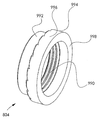
이제, 만곡형 샤프트 어셈블리 위치결정 링(804)을 예시하는 도 7n 및 도 7o에 대한 추가적인 참조가 이루어진다. 만곡형 샤프트 어셈블리 위치결정 링(804)은 바람직하게는 나사산이 형성된 내부 구멍(990)을 갖는 전반적인 원통형 링이며, 이는, 도 7p의 확대도 D에서 구체적으로 보여지는 바와 같이, 만곡형 샤프트 어셈블리 내부 엘리먼트(802)의 나사산이 형성된 반원통형 외부 표면들(952) 위에 선택적인 나사결합으로 축 방향으로 위치될 수 있다. 링(804)은 바깥쪽을 향한 원통형 표면(992) 및 바깥쪽을 향한 원통형 플랜지 표면(996) 및 전방을 향한 환형 플랜지 표면(998)을 갖는 플랜지(994)를 획정한다.Additional reference is now made to Figs. 7n and 7o illustrating a curved shaft
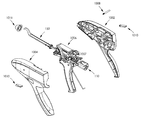
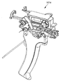
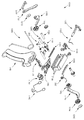
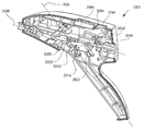
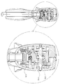
이제 도 8a, 도 8b, 도 8c, 도 8d, 도 8e, 도 8f, 도 8g, 도 8h, 도 8i, 도 8j, 도 8k, 도 8l, 도 8m, 도 8n, 도 8o, 도 8p, 도 8q, 도 8r, 도 8s, 도 8t, 도 8u, 도 8v, 도 8w, 도 8x, 도 8y, 도 8z, 도 8aa, 도 8ab, 도 8ac, 도 8ad, 도 8ae, 도 8af, 도 8ag, 도 8ah, 도 8ai, 도 8aj, 도 8ak, 도 8al, 도 8am, 도 8an, 도 8ao, 도 8ap, 도 8aq, 도 8ar, 도 8as, 도 8at, 도 8au, 도 8av, 도 8aw, 도 8ax, 도 8ay, 도 8az, 도 8ba, 도 8bb, 도 8bc, 도 8bd, 도 8be, 도 8bf, 도 8bg, 도 8bh, 도 8bi, 도 8bj, 도 8bk, 도 8bl, 도 8bm, 도 8bn, 도 8bo, 도 8bp, 도 8bq, 도 8br, 도 8bs, 도 8bt, 및 도 8bu에 대한 참조가 이루어지며, 이러한 도면들은 도 1a 및 도 1b의 관절경 수술 어셈블리의 부분을 형성하는 관절경 수술 디바이스(160)의 간략화된 예시들이다.8A, 8B, 8C, 8D, 8E, 8F, 8G, 8H, 8I, 8J, 8K, 8L, 8M, 8N, 8O, 8P, 8q, 8r, 8s, 8t, 8u, 8v, 8w, 8x, 8y, 8z, 8aa, 8ab, 8ac, 8ad, 8ae, 8f, 8ag, 8A, 8A, 8A, 8A, 8A, 8A, 8A, 8A, 8A, 8A, 8A, 8A, 8A, 8A, 8A, 8A, 8b, 8b, 8b, 8b, 8b, 8b, 8b, 8b, 8b, 8b, 8b, 8b, 8b, 8b, 8b, 8b, 8bp, 8bq, 8br, 8bs, 8bt, and 8bu, which illustrate an arthroscopic device (FIG. 8a) that forms part of the arthroscopic surgical assembly of FIGS. 1a and
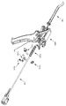
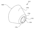
도 8a 및 도 8b는 각기 관절경 수술 디바이스(160)의 후방을 향한 분해도 예시 및 전방을 향한 부분적인 분해도 예시이다. 도 8a 및 도 8b에서 보여지는 바와 같이, 관절경 수술 디바이스(160)는 제 1 및 제 2 하우징 부분들(1002 및 1004)을 포함하며, 이들은, 작업 채널 어셈블리(110)(도 3a 내지 도 3n) 및 만곡형 샤프트 어셈블리(150)(도 7a 내지 도 7p)을 포함하는 것으로 도시된 관절경 수술 메커니즘(1006) 및 작업 채널 어셈블리(110)와 연관된 스프링(1007)을 봉입한다. 도 8a 및 도 8b에서 또한 보여지는 바와 같이, 스토퍼 핀(stopper pin)(1008), 구동 방향 선택기 레버(1010), 및 제 1 및 제 2 하우징 부분들(1002 및 1004)을 함께 만곡형 샤프트 어셈블리(150) 위에 그리고 이와 맞물리게 유지하기 위하여 동작하는 유지 콘(1011)이 존재한다.FIGS. 8A and 8B are an illustration of an exploded view of the
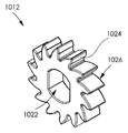
도 8c는, 작업 채널 어셈블리(110)의 견인을 위하여 동작하는 엘리먼트들(1012, 1014, 1016 및 1018)이 개별적으로 도시되는 관절경 수술 메커니즘(1006)의 부분적인 분해도를 도시한다. 도 8d에서 구체적으로 보여지는 바와 같이, 엘리먼트(1012)는 비-원형 개구(1022)를 가지며 다수의 기어 티쓰(1026)의 각각 상에 구동 표면들(1024)을 획정하여 결과적으로 선형 래칫 기어 트랙(304)(도 3h - 도 3j)과 맞물리는 래칫 기어이다.Figure 8c shows a partial exploded view of the arthroscopic
엘리먼트(1014)는 도 8e 및 도 8f에 도시되며, 거기를 따라 중간에 위치되는 래칫 기어 부분(1032)을 가지며 그것의 다수의 기어 티쓰(1036)의 각각 상에 구동 표면들(1034)을 획정하는 원통형 액슬(1030)을 포함하고 바람직하게는 이와 일체로 형성되는 액슬-장착형 기어이다. 원통형 액슬(1030)의 제 1 단부(1038)에는, 바람직하게는 6각형 단면 및 대향적으로 향하는 평평한 측면 표면 부분들(1042)의 쌍이 제공된다. 래칫 기어(1012)는 바람직하게는 원통형 액슬(1030)의 제 1 단부(1038) 상에 장착된다.The
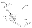
도 8g에 도시된 엘리먼트(1016)는, 축(1045) 둘레로 배열된 코일(1044) 및 축(1045)에 대하여 방사상으로 연장하는 스프링 단부 암들(1046 및 1048)의 쌍을 갖는 회전 강제 스프링이다.The
엘리먼트(1018)는 대향되는 방향들로부터 도 8h 및 도 8i에 도시되며, 이는, 관절경 수술 디바이스(160)에 대하여 작업 채널 어셈블리(110)를 선택적으로 로킹하고 릴리즈하는 작업 채널 어셈블리 유지 후크 엘리먼트이다. 작업 채널 어셈블리 유지 후크 엘리먼트(1016)는 바람직하게는 플라스틱으로 일체로 형성되며, 그것의 극단 단부에서 언더컷 후크(1054)를 갖는 암이 그것의 측면으로부터 연장하는 원통형 액슬 부분(1050)을 포함한다. 후크(1054)는 경사진 외부 표면(1056) 및 경사진 내부 표면(1058)을 포함한다. 횡방향 구멍(1060)는 표면(1056) 아래의 후크(1054)를 통해 연장하며, 스프링 단부 암(1046)을 수용한다.The
암(1052)은, 중간 암 부분(1064)에 의해 후크(1054)로부터 분리된 만곡된 캠(cam) 표면(1062)을 포함한다.The
후크(1054)가 스프링(1016)에 의해 작업 채널 어셈블리(110)의 메인 원통형 부분(234)의 횡방향 언더컷(294)와 맞물리도록 강제되어 작업 채널 어셈블리(110)를 관절경 수술 디바이스(160)에 대하여 로킹한다는 것이 이해될 것이다.The
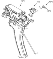
이제 관절경 수술 메커니즘(1006)의 추가적이고 부분적인 분해도를 도시하는 도 8j에 대한 추가적인 참조가 이루어지며, 이러한 도면에서 카트리지 어셈블리 유지 엘리먼트(1070), 유지 암(1073)을 획정하는 카트리지 어셈블리 유지 스프링(1072) 및 수동 작동가능 구동 엔진 어셈블리(1074)가 분리된다. 카트리지 어셈블리 유지 엘리먼트(1070)는 도 8k, 도 8l 및 도 8m에 예시되며, 바람직하게는 플라스틱으로 만들어진 일체로 형성된 엘리먼트이다. 카트리지 유지 엘리먼트(1070)는 바람직하게는, 축(1081)을 따라 연장하며 그것의 측면으로부터 연장하는 카트리지 유지 암(1082)을 갖는 액슬(1080)을 포함한다. 암(1082)은 단부 표면(1083) 및 측면 표면(1084)을 획정한다.8J, which illustrates an additional, partial exploded view of the arthroscopic
수동으로 맞물릴 수 있는 회전자(rotator) 표면 획정 부분(1085)이 암(1082)의 방향과 전반적으로 대향되는 방향으로 액슬(1080)의 측면으로 연장하며, 이는, 표면(1086)과의 수동 맞물림이 충분하지 않을 때, 축(1081) 둘레로 카트리지 유지 엘리먼트(1070)의 회전을 제공하기 위하여 레버(미도시)에 의한 그 사이의 맞물림을 위한 노치(1080), 후방의 볼록한 표면(1087), 및 최전방의 볼록한 표면(1087)을 포함하는 스플라인이 형성된(splined) 엄지 맞물림 표면(1086)을 획정한다.A manually engageable rotator
캠 표면(1092)을 획정하는 카트리지 릴리즈 캠 부분(1090)이 또한 부분(1085)에 인접한 액슬(1080)의 측면으로부터 연장한다.A cartridge
이제 도 8n 및 도 8o, 및 도 8p 및 도 8q에 대한 참조가 이루어지며, 이러한 도면들은 각기, 각각의 쌍이 대향되는 방향으로부터 취해진 수동 작동가능 구동 엔진 어셈블리(1074)의 조립된 도면 및 분해된 도면 예시들의 쌍들이다.Reference is now made to Figs. 8n and 8o and Figs. 8p and 8q, which illustrate an assembled view of the manually operable
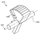
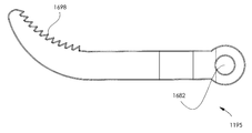
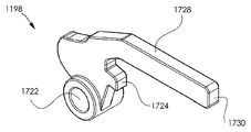
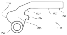
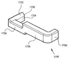
도 8n 내지 도 8q에서 보여지는 바와 같이, 수동 작동가능 구동 엔진 어셈블리(1074)는, 이하에서 도 8r 내지 도 8u를 참조하여 상세하게 설명되는 메인 섀시(1100), 이하에서 도 8v 내지 도 8y를 참조하여 상세하게 설명되는 보조 섀시(1110), 이하에서 도 8z 내지 도 8ab를 참조하여 상세하게 설명되는 카트리지 푸셔(1120); 이하에서 도 8ac를 참조하여 상세하게 설명되는 카트리지 푸셔 커넥터(1130); 이하에서 도 8ad 내지 도 8ag를 참조하여 상세하게 설명되는 손으로 쥘 수 있는 구동 핸들(1140); 이하에서 도 8ah 내지 도 8ak를 참조하여 상세하게 설명되는 메인 구동 방향 시프팅 엘리먼트(1150); 이하에서 도 8al 내지 도 8ao를 참조하여 상세하게 설명되는 시프트가능 엘리먼트(1160); 이하에서 도 8ap 내지 도 8ar을 참조하여 상세하게 설명되는 구동 방향 선택기 레버 응답 토글 엘리먼트(1170); 이하에서 도 8as를 참조하여 상세하게 설명되는 구동-시프팅 스프링(1180); 이하에서 도 8at 내지 도 8au를 참조하여 상세하게 설명되는 후방 구동 방향 기어 랙(1190), 이하에서 도 8av 내지 도 8aw를 참조하여 상세하게 설명되는 전방 구동 기어 랙(1191); 이하에서 도 8ax 내지 도 8ay를 참조하여 상세하게 설명되는 클러치(1192); 이하에서 도 8az를 참조하여 상세하게 설명되는 후방 구동 기어(1193); 이하에서 도 8ba를 참조하여 상세하게 설명되는 메인 구동 기어(1194); 이하에서 도 8bb 및 도 8bc를 참조하여 상세하게 설명되는 바늘 구동 래칫 암(1195); 이하에서 도 8bd를 참조하여 상세하게 설명되는 전방 구동 기어(1196); 이하에서 도 8be 및 도 8bf를 참조하여 상세하게 설명되는 작업 채널 견인 래칫 암(1197); 이하에서 도 8bg 및 도 8bh를 참조하여 상세하게 설명되는 피봇가능 암(1198) 및 이하에서 도 8bi 및 도 8bj를 참조하여 상세하게 설명되는 쉬프트가능 링크(1199)를 포함한다.As shown in Figures 8n-8q, the manually operable
수동 작동가능 구동 엔진 어셈블리(1074)는 또한, 단부들(1202 및 1203)을 갖는 구동 핸들 스프링(1201); 메인 구동 방향 시프팅 엘리먼트 스프링(1204), 핸들 피봇 액슬(1206), 구동 핀(1208); 제 1 및 제 2 와셔들(1210 및 1212); 및 래칫 암 강제 스프링(1222)을 포함한다.The manually operable
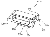
이제 메인 섀시(1100)를 도시하는 도 8r 내지 도 8u에 대한 참조가 이루어진다. 도 8r 내지 도 8u에서 보여지는 바와 같이, 메인 새시(1100)는, 상단 부분(1250), 하단 부분(1252), 전방 측면 부분(1254), 후방 측면 부분(1256), 전방 측면 부분(1254)로부터 연장하며 에지 표면(1259)을 갖는 전방으로 향해진 돌출부(1258) 및 상단 부분(1250)으로부터 후방으로 연장하는 후방 연장 돌출부(1260)를 갖는 전반적인 직사각형 엘리먼트이다.Reference is now made to Figs. 8r-8u illustrating the
전방 측면 부분(1254)과 후방 측면 부분(1256) 사이에서 상단 부분(1250) 아래에 후방 구동 기어 랙(1190)을 수용하는 소켓(1262)이 배치된다.A
전방 측면 부분(1254)과 후방 측면 부분(1256) 사이에서 하단 부분(1252) 위에 전방 구동 기어 랙(1191)을 수용하는 소켓(1270)이 배치된다.Between the
도 8r에서 보여지는 바와 같이, 세장형 상단 표면(1274) 및 세장형 에지 표면(1276)을 갖는 세장형 돌출부(1272)가 하단 부분(1252)의 일 측면을 따라 배치된다. 도 8r의 풍선꼴 윤곽에서 보여지는 바와 같이, 카트리지 푸셔 커넥터(1130)와 맞물리도록 함께 작동하는 개구(12778), 리세스된 표면(1278) 및 반원형 세장형 돌출부(1279)가 메인 섀시(1100)의 후방 측면 상에서 후방 측면 부분(1256)에 대향되어 존재한다. 카트리지 푸셔 커넥터(1130)의 횡방향 부분(1398)은 개구(1277) 내에 안착되며, 카트리지 푸셔 커넥터(1130)의 만곡된 중간 부분(1397)은 리세스된 표면(1278)에 기대어 존재하고 추가로 반원형 세장형 돌출부(1279)에 의해 지지된다. 도 8s에서 보여지는 바와 같이, 세장형 상단 표면(1284) 및 세장형 에지 표면(1286)을 갖는 세장형 돌출부(1282)가 하단 부분(1252)의 대향되는 측면을 따라 배치된다.As shown in FIG. 8r,
도 8t에서 보여지는 바와 같이, 세장형 상단 표면(1294) 및 세장형 에지 표면(1296)을 갖는 세장형 돌출부(1292)가 상단 부분(1250)의 일 측면을 따라 배치된다. 도 8r에서 보여지는 바와 같이, 세장형 상단 표면(1304) 및 세장형 에지 표면(1306)을 갖는 세장형 돌출부(1302)가 상단 부분(1250)의 대향되는 측면을 따라 배치된다. 푸시 막대(820)의 부분(902)과 맞물리는 세장형 푸시 막대 유지 소켓(1310)이 전방 측면 부분(1254)로부터 후방으로 연장한다. 푸시 막대(820)의 부분(900)을 수용하는 리세스(1312)가 소켓(1310)의 후방에 존재한다.As shown in Figure 8t,
만곡된 전방으로 그리고 아래쪽으로 지향된 캠 표면(1322)을 획정하는 캠 돌출부(1320)가 후방 측면 부분(1256)으로부터 후방으로 그리고 횡방향으로 연장한다. 후방으로 연장하는 돌출부(1260)는 만곡된 후방으로 그리고 아래쪽으로 연장하는 캠 표면(1328)을 포함하며, 또한 위쪽을 향한 표시기 표면(1332)을 갖는 위쪽으로 그리고 횡방향으로 연장하는 부분(1330)을 획정한다.A cam protrusion 1320 that defines a curved forward and downwardly directed cam surface 1322 extends rearwardly and laterally from the
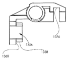
이제 보조 섀시(1110)를 도시하는 도 8v 내지 도 8y에 대한 참조가 이루어진다. 보조 섀시(1110)는, 도 8p의 의미에서 경사진 평평한 표면(1352)으로 전방으로 연장하는 상단의 전반적으로 평평한 표면(1350)을 포함한다. 액슬 장착형 기어 엘리먼트(1014)의 원통형 액슬(1030)을 회전가능하게 수용하는 전반적으로 원통형 소켓(1354)이 평평한 표면(1350) 아래에 존재하며 횡방향으로 연장한다. 소켓(1354)의 후방으로, 보조 섀시(1110)는 그것의 외부 표면들(1358 및 1360)이 함께 스프링(1007)(도 8a 내지 도 8c)에 대한 스프링 시트를 획정하는 전반적으로 원통형 축 방향 소켓(1356)을 획정한다.
보조 섀시(1110)는 또한 표면들(1372, 1374 및 1376)에 의해 획정되는 장착 소켓(1370)을 획정한다.Reference is now made to Figs. 8V through 8Y illustrating the
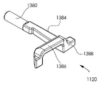
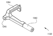
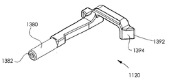
이제 카트리지 푸셔(1120)를 예시하는 도 8z 내지 도 8ab에 대한 참조가 이루어진다. 카트리지 푸셔(1120)는 바람직하게는, 카트리지 푸셔 커넥터(1130)의 단부를 수용하는 세장형 구멍(1382)을 갖는 전반적인 원통형 부분(1380)을 포함한다. 원통형 부분(1380)의 후방에는, 횡방향으로 연장하는 후방 부분(1386)까지 연장하며 후방을 향한 표면(1388)을 가지고 및 제 1 단부 부분(1390) 및 경사진 평평한 표면(1394)을 갖는 제 2 단부 부분(1392)을 갖는 중간 암 부분(1384)이 존재한다.Reference is now made to Figs. 8z to 8ab illustrating the
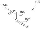
이제 카트리지 푸셔 커넥터(1130)을 예시하며, 카트리지 푸셔(1120)의 세장형 구멍(1382) 내에 안착되는 축 방향 부분(1396), 만곡된 중간 부분(1397) 및 메인 섀시 부분(1100) 내에 형성된 개구(1277) 내에 안착되는 횡방향 부분(1398)을 포함하는 도 8ac에 대한 참조가 이루어진다.Illustrating the
이제 손으로 쥘 수 있는 구동 핸들(1140)을 예시하는 도 8ad 내지 도 8ag에 대한 참조가 이루어진다. 손으로 쥘 수 있는 구동 핸들(1140)은 바람직하게는 하나의 피스로서 플라스틱으로부터 몰딩되며, 그립 부분(1400) 및 받침(rest) 부분(1402)을 포함한다. 손으로 쥘 수 있는 구동 핸들(1140)은 바람직하게는 전반적으로 평행한 직립 부분들(1404 및 1406)의 쌍을 포함하며, 이들의 각각은 전방 개구(1408) 및 후방 개구(1410)를 갖도록 형성된다. 직립 부분들(1404 및 1406)의 전방 개구들(1408)은 횡방향으로 상호 정렬되며, 구동 핀(1208)을 수용한다. 직립 부분들(1404 및 1406)의 후방 개구들(1410)은 횡방향으로 상호 정렬되며, 핸들 피봇 액슬(1206)을 수용한다.Reference is now made to Figs. 8ad-8ag illustrating a hand-
직립 부분들(1404 및 1406)은 각각 정지부(stop) 맞물림 표면(1411)을 획정한다.The
도 8af에서 구체적으로 보여지는 바와 같이, 전반적으로 평행한 직립 부분들(1404 및 1406)의 쌍은 함께 상부 및 하부 스프링 유지 슬롯들(1412 및 1414)을 획정한다.The pair of generally parallel
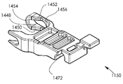
이제 메인 구동 방향 시프팅 엘리먼트(1150)를 도시하는 도 8ah 내지 도 8ak에 대한 참조가 이루어진다. 도 8ah 내지 도 8ak에서 보여지는 바와 같이, 메인 구동 방향 시프팅 엘리먼트(1150)는 그것의 전방 부분에서 개방 소켓(1418)을 획정하는 제 1 암(1416) 및 제 1 암(1416)으로부터 이격되며 폐쇄 소켓(1422)을 획정하는 제 2 암(1420)을 포함한다. 개방 소켓(1418) 및 폐쇄 소켓(1422)은 함께 메인 구동 방향 시프팅 엘리먼트(1150)을 슬라이딩가능하게 수용한다.Reference is now made to Figs. 8ah-8ak showing the main drive
개방 소켓(1418)은, 그 중에서도, 반-원통형 표면(1424) 및 개별적인 상단 및 하단의 전방 테이퍼진 표면(1426 및 1428)에 의해 획정된다. 제 1 암(1416)은 또한, 안쪽으로 향한 각이 진 하단 에지 표면(1430), 안쪽으로 향한 각이 진 상단 에지 표면(1432), 아크-형의 안쪽으로 향한 표면(1434)에 의해 획정된다. 개별적인 상단 및 하단 전방 돌출부들(1436 및 1438)은 개별적인 에지 표면들(1430 및 1432)의 전방으로 연장한다. 폐쇄 소켓(1422)은, 그 중에서도, 반-원통형 표면(1444) 및 개별적인 상단 및 하단의 후방 테이퍼진 표면(1446 및 1448)에 의해 획정된다. 제 2 암(1420)은 또한, 안쪽으로 향한 각이 진 하단 에지 표면(1450), 안쪽으로 향한 각이 진 상단 에지 표면(1452), 개별적인 외부 및 내부 아크-형의 안쪽으로 향한 표면들(1454 및 1456)에 의해 획정된다.The open socket 1418 is defined by, among other things, the
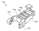
측벽들(1460 및 1462) 및 횡방향 벽들(1464, 1466 및 1468)을 포함하는 중심 부분이 제 1 및 제 2 암들(1416 및 1420)의 후방으로 연장한다. 측벽(1462)은 스프링(1204)을 수용하기 위한 스프링 단부 맞물림 개구(1470)를 갖도록 형성된다. 중심 부분의 후방에는, 피봇가능하게 구동 방향 선택기 레버 응답 토글 엘리먼트(1170)를 수용하는 횡방향 반원통형의 아래쪽으로 향한 횡방향 소켓(1472)을 포함하는 단부 부분이 존재한다.A central portion including sidewalls 1460 and 1462 and
소켓(1472)의 후방에는, 전방 에지 표면(1478)을 갖는 위쪽으로 지향된 테이블(1476)을 획정하는 단부 부분(1474)이 제공된다.At the rear of the
이제, 메인 구동 방향 시프팅 엘리먼트(1150)의 개별적인 개방 및 폐쇄 소켓들(1416 및 1420)에 의해 슬라이딩이 가능하게 유지되는 시프트가능 엘리먼트(1160)를 예시하는 도 8al 내지 도 8ao에 대한 참조가 이루어진다. 시프트가능 엘리먼트(1160)는 바람직하게는 플라스틱으로 사출 몰딩되며, 각기 개방 소켓(1416) 및 폐쇄 소켓(1420)과 맞물리는 개별적인 액슬들(1506 및 1508)을 갖는 동일한 제 1 및 제 2 측면 부분들(1502 및 1504) 및 중심 부분(1500)을 포함한다.Reference is now made to Figures 8al to 8ao illustrating a
제 1 및 제 2 측면 부분들(1502 및 1504)은 개별적인 전반적으로 볼록한 캠 맞물림 표면들(1512 및 1514)을 획정하며, 그 각각이 개별적인 아래쪽을 향한 평평한 표면들(1516 및 1518)을 획정한다. 중심 부분(1500)은 바람직하게는 거의 원주방향 스프링 맞물림 표면(1520) 및 방향-시프팅 스프링(1180)과의 맞물림을 위한 거의 원주방향 에지 표면(1522)을 획정한다. 표면들(1520 및 1522)은 방향-시프팅 스프링(1180)에 대한 스프링 시트(1530)를 획정하기 위하여 제 1 및 제 2 측면 부분들의 대응하여 향한 에지 표면들(1524 및 1526)과 협력한다.First and
이제 구동 방향 선택기 레버 응답 토글 엘리먼트(1170)를 예시하는 도 8ap 내지 도 8ar에 대한 참조가 이루어진다. 구동 방향 선택기 레버 응답 토글 엘리먼트(1170)는 바람직하게는 단일 엘리먼트이며, 플라스틱으로 사출 몰딩되고, 측면 지향된 암들(1554 및 1556)의 쌍 및 그 사이에서 연장하는 세장형 부분들(1158 및 1560)의 쌍을 포함하는, 횡방향 부분(1552) 및 메인 축 방향 부분(1550)을 포함한다.Reference is now made to Figs. 8ap to 8ar illustrating a drive direction selector lever
메인 축 방향 부분(1550)은 바람직하게는, 축 방향 단부 돌출부들(1562 및 1564)의 쌍을 포함하며, 이들은 바람직하게는 6각형 단면을 갖는다. 세장형 부분(1560)은 바람직하게는 평평한 캠 표면들(1568 및 1570)의 쌍을 포함하며, 메인 구동 방향 시프팅 엘리먼트(1150)의 반원통형의 아래쪽으로 향한 횡방향 소켓(1472)과 맞물린다.The main axial portion 1550 preferably includes a pair of
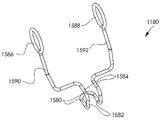
이제 방향 시프팅 스프링(1180)을 예시하는 도 8as에 대한 참조가 이루어진다. 도 8as에서 보여지는 바와 같이, 방향 시프팅 스프링(1180)은, 제 1의 전반적으로 평평한 중간 부분(1582)을 획정하기 위하여 약 90도만큼 구부러지고 제 2의 전반적으로 평평한 중간 부분(1584)을 획정하기 위하여 약 90도만큼 더 구부러진 중심의 전반적으로 평평한 루프 부분(1580)을 포함한다. 부분들(1580, 1582 및 1584)은 바람직하게는 시프트가능 엘리먼트(1160)의 스프링 시트(1530)와 맞물린다.Reference is now made to Fig. 8as illustrating the
폐쇄 루프 링들(1586 및 1588)의 쌍이 스프링 암들(1590 및 1592)의 개별적인 단부들을 획정하며, 이들은 결과적으로 제 2의 전반적으로 평평한 중간 부분(1584)의 개별적인 단부들의 연장부들이다.The pairs of closed loop rings 1586 and 1588 define the individual ends of the
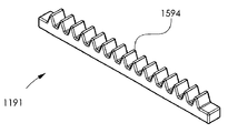
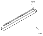
이제 전방 구동 기어 랙(1191)을 예시하는 도 8at 내지 도 8au에 대한 참조가 이루어진다. 전방 구동 기어 랙(1191)이 각기 후방을 향한 맞물림 표면(1596)을 갖는 다수의 선형으로 배열된 기어 티쓰(1594)를 포함한다는 것이 보여진다.Reference is now made to Figs. 8at to 8au illustrating the front
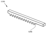
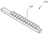
이제 후방 구동 기어 랙(1190)을 예시하는 도 8av 내지 도 8aw에 대한 참조가 이루어진다. 후방 구동 기어 랙(1190)이 각기 전방을 향한 맞물림 표면(1598)을 갖는 다수의 선형으로 배열된 기어 티쓰(1597)를 포함한다는 것이 보여진다.Reference is now made to Figs. 8av through 8aw illustrating a rear
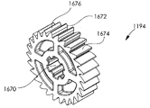
이제 클러치(1192)를 예시하는 도 8ax 및 도 8ay에 대한 참조가 이루어진다. 도 8ax 및 도 8ay에서 보여지는 바와 같이, 클러치(1192)는 그 안에 형성된 6각형 리세스(1604)를 가지며 제 1 직경을 갖는 제 1의 전반적인 원형의 원통형 단부 부분(1602)을 갖는 세장형 액슬(1600)를 포함한다. 제 1 단부 부분(1602)는 제 1 직경보다 더 큰 제 2 직경을 갖는 제 2의 원형의 원통형 부분(1608)을 구비한 숄더(1606)를 획정한다.Reference is now made to Figs. 8ax and 8ay illustrating clutch 1192. Fig. As shown in Figures 8ax and 8ay, clutch 1192 has a
제 2 부분(1608)은 기어 디스크 부분(1612)의 제 1 환형 표면(1610)에서 끝나며, 이는 또한 제 2 환형 표면(1614)을 갖도록 형성된다. 제 1 환형 표면(1610)은 기어 티스(1616)의 원형 어레이를 갖도록 형성되며, 이들의 각각은 도 8ax의 의미에서 그것의 반시계방향을 향한 에지 상에 배열된 투쓰 맞물림 표면(1618)을 갖는다. 제 2 환형 표면(1614)은 기어 티스(1620)의 원형 어레이를 갖도록 형성되며, 이들의 각각은 도 8ax의 의미에서 그것의 반시계방향을 향한 에지 상에 그리고 도 8ay의 의미에서 그것의 시계방향을 향한 에지 상에 배열된 투쓰 맞물림 표면(1622)을 갖는다.The
제 2 직경과 동일한 제 3 직경을 갖는 제 3의 원형의 원통형 부분(1628)이 제 2 환형 표면(1614)를 넘어 연장하며, 도 8ax의 의미에서 거기를 넘어 외부를 향한 선형적으로 스플라인이 형성된 부분(1630)이 존재하여, 제 1의 원형의 원통형 부분(1602)의 직경과 동일한 직경을 갖는 제 4의 원형의 원통형 부분(1632)이 이어진다.A third circular
이제 후방 구동 기어(1193)를 예시하는 도 8az에 대한 참조가 이루어진다. 도 8az에서 보여지는 바와 같이, 후방 구동 기어(1193)는 이의 하나의 평평한 표면으로부터 복합 기어 티쓰(1654)의 원형 어레이(1652)가 연장하는 디스크-형 부분(1650)을 포함한다. 각각의 투쓰(1654)에는 볼록한 대향적으로 향한 구동 표면들(1656)이 구비되는 것이 보여진다. 이에 더하여, 각각의 투쓰에는 도 8az의 의미에서 평평한 시계방향을 향한 구동되는 표면(1658)이 구비된다. 후방 구동 기어(1193)에는, 클러치(1192)의 제 3의 원형의 원통형 부분(1628)을 수용하는 중심 구멍(1660)이 구비된다는 것이 또한 보여진다.Reference is now made to Fig. 8az illustrating the
이제 메인 구동 기어(1194)를 예시하는 도 8ba에 대한 참조가 이루어진다. 도 8b에서 보여지는 바와 같이, 메인 구동 기어(1194)는 전반적으로 디스크-형 구성이며, 클러치(1192)의 구동을 위하여 외부를 향한 선형적으로 스플라인이 형성된 부분(1630)을 수용하는 중심 스플라인이 형성된 구멍(1670)을 갖도록 형성된다. 메인 구동 기어는, 각각이 시계방향을 향한 전반적으로 평평한 구동되는 표면(1676)을 갖는 기어 티쓰(1674)의 원형 어레이를 포함한다.Reference is now made to Figure 8ba, which illustrates the
이제 바늘-구동 래칫 암(1195)을 예시하는 도 8bb 및 도 8bc에 대한 참조가 이루어진다. 도 8bb 및 도 8bc에서 보여지는 바와 같이, 바늘-구동 래칫 암은 구동 핀(1208)을 피봇가능하게 수용하기 위한 피봇 액슬 수용 개구(1682)를 포함하는 피봇 부분(1680)을 포함하며, 래칫 암(1195)은, 각각이 전반적으로 평평한 구동 표면(1692)을 갖는 기어 티쓰(1690)의 만곡된 세장형 어레이(1688)를 그것의 내부 만곡된 표면 상에 갖는 만곡된 기어 맞물림 부분(1686)이 이로부터 연장하는 전반적으로 직선의 중간 부분(1684)을 포함한다.Reference is now made to Figs. 8bb and 8bc illustrating the needle-driven
이제 전방 구동 기어(1196)를 예시하는 도 8bd에 대한 참조가 이루어진다. 도 8bd에서 보여지는 바와 같이, 전방 구동 기어(1196)는, 이의 하나의 평평한 표면으로부터 복합 기어 티쓰(1695)의 원형 어레이(1694)가 연장하는 디스크-형 부분(1693)을 포함한다. 각각의 투쓰(1695)에는 볼록한 대향하여 향한 구동 표면들(1696)의 쌍이 구비된다. 이에 더하여, 각각의 투쓰에는 도 8bd의 의미에서 평평한 반시계 방향을 향한 구동되는 표면(1698)이 구비된다. 전방 구동 기어(1196)에는, 클러치(1192)의 제 2의 원형의 원통형 부분(1608)을 수용하는 중심 구멍(1699)이 구비되는 것이 또한 보여진다.Reference is now made to Fig. 8bd illustrating forward drive
이제 작업 채널 견인 래칫 암(1197)을 예시하는 도 8be 및 도 8bf에 대한 참조가 이루어진다. 도 8be 및 도 8bc에서 보여지는 바와 같이, 작업 채널 견인 래칫 암(1197)은 구동 핀(1208)을 피봇가능하게 수용하기 위한 피봇 액슬 수용 개구(1702)를 포함하는 피봇 부분(1700)을 포함하며, 래칫 암(1197)은, 각각이 전반적으로 평평한 구동 표면(1712)을 갖는 기어 티쓰(1710)의 만곡된 세장형 어레이(1708)를 그것의 외부 만곡된 표면 상에 갖는 만곡된 기어 맞물림 부분(1706)이 이로부터 연장하는 전반적으로 직선의 중간 부분(1704)을 포함한다.Reference is now made to Figs. 8B and 8BF illustrating the working channel towing
이제 피봇가능 암(1198)을 예시하는 도 8bg 및 도 8bh에 대한 참조가 이루어진다. 도 8bg 및 도 8bh에서 보여지는 바와 같이, 피봇가능 암(1198)은, 작업 채널 어셈블리 유지 후크 엘리먼트(1018)를 피봇가능하게 수용하기 위한 피봇 액슬 수용 개구(1722)를 포함하는 피봇 부분(1720)을 포함한다. 피봇가능 암(1198)은, 작업 채널 어셈블리 유지 후크 엘리먼트(1018)의 중간 암 부분(1064)과 맞물리는 볼록한 표면(1725) 및 볼록한 표면(1726)을 획정하는 돌출부(1724)를 갖는 중간 부분(1723)을 포함한다. 세장형 부분(1727)은 중간 부분(1723)으로부터 바깥쪽으로 연장하며, 상단 표면(1728), 하단 표면(1729) 및 단부 표면(1730)을 갖는다.Reference is now made to Figs. 8bg and 8bh illustrating
이제 시프트가능 링크(1199)를 예시하는 도 8bi 및 도 8bj에 대한 참조가 이루어진다. 도 8bi 및 도 8bj에서 보여지는 바와 같이, 시프트가능 링크(1199)는, 전방 및 상단을 향한 만곡된 세장형 부분(1752) 및 전반적으로 평평한 전방을 향한 세장형 부분(1754)을 포함하는 제 1 암 부분(1750)을 포함한다. 제 1 세장형 부분(1756)이 제 1 암 부분(1750)에 수직으로 연장하며, 이는 제 1 세장형 부분(1756)에 대하여 위쪽으로 오프셋(offset)된 제 2 세장형 부분(1758)까지 연장한다. 제 2 암 부분(1760)은 제 2 세장형 부분(1758)로부터 그리고 전반적으로 이에 대하여 수직으로 연장하며, 후방을 향한 전반적으로 평평한 표면(1762)을 획정한다.Reference is now made to Figs. 8bi and 8bj illustrating the
이제 구동 방향 선택기 레버(1010)를 예시하는 도 8bk 및 도 8bl에 대한 참조가 이루어진다. 도 8bk 및 도 8bl에서 보여지는 바와 같이, 구동 방향 선택기 레버(1010)는 상부 및 하부 핑거 접촉 표면들(1770 및 1772) 각각, 내부 표면(1773) 및 축 방향 단부 돌출부들(1562 및 1564) 중 하나를 수용하기 위한 6각형 리세스(1776)를 갖는 피봇 부분(1774)을 포함한다.Reference is now made to Figures 8bk and 8b, which illustrate the drive
이제 스토퍼 핀(1008)을 예시하는 도 8bm에 대한 참조가 이루어진다. 스토퍼 핀(1008)은, 메인 부분(1778), 나사산이 형성된 단부(1780) 및 나사산이 형성된 단부(1780)에 대향되는 단부(1784)에서의 6각형 소켓(1782)을 갖는 전반적으로 원통형 엘리먼트이다.Reference is now made to Fig. 8bm illustrating the
이제 전반적으로 중공형 유지 콘(1011)을 예시하는 도 8bn 및 도 8bo에 대한 참조가 이루어진다. 유지 콘(1011)은 바람직하게는 외부의 전반적으로 절두 원뿔형 표면(1790)을 갖는다. 그것의 좁은 단부(1792)에서, 유지 콘(1011)은 경사진 환형 표면(1794)을 획정한다. 경사진 환형 표면의 내부에 그 안에 형성된 라운드형(rounded) 직사각형 개구(1798)를 갖는 전반적으로 평평한 표면(1796)이 형성된다.Reference is now made to Figs. 8Bn and 8Bo, which generally illustrate the
그것의 넓은 단부(1800)에서, 유지 콘(1011)은, 원주방향 내부 리세스된 벽(1810)으로 평평한 표면(1802)의 내부로 연장하는 3개의 전반적으로 균일하게 방위각적으로 분포된 리세스들(1808)을 포함하는 내부 원주방향 개구 벽(1806)을 갖는 원형 개구(1804)를 포함하는 평평한 표면(1802)을 획정한다.At its
이제, 각기 제 1 하우징 부분(1002)의 내부 및 외부 표면들의 간략화된 도식적 예시들 및 제 1 하우징 부분의 내부 하우징 표면의 평면도 예시인 도 8bp, 도 8bq 및 도 8br에 대한 참조가 이루어진다.Reference is now made to Figs. 8bp, 8bq and 8br, which are illustrative of simplified schematic illustrations of the inner and outer surfaces of the
도 8bp 내지 도 8br에서 보여지는 바와 같이, 제 1 하우징 부분(1002)이 메인 구동 축(1900) 및 바람직하게는 132.5도만큼 메인 구동 축(1900)에 대하여 각이 진 축(1904)을 갖는 손으로 쥘 수 있는 구동 핸들 부분(1902)을 획정하는 것이 보여진다. 제 1 하우징 부분(1002)의 전방 단부에는, 바람직하게는 유지 콘(1011)의 넓은 단부(1800)와 맞물리는 콘 맞물림 표면(1906)이 획정된다. 콘 맞물림 표면(1906)의 전방에는 콘 맞물림 표면(1906)에 인접한 원주방향 리세스(1910)를 갖는 반원통형 콘 맞물림가능 부분(1908)이 존재한다. 원주방향 리세스(1910)의 전방에는 원주방향 돌출부(1912)가 존재하며, 원주방향 돌출부(1912)의 전방에는 다른 원주방향 리세스(1914)가 존재한다. 리세스들(1910 및 1912) 및 돌출부(1914)는 유지 콘(1011)의 원주방향 개구 벽(1806)과 스냅-핏 맞물림을 위하여 배열된다.As shown in Figures 8bp-8br, the
제 1 하우징 부분(1002)의 외부 표면은, 개구(1922)를 포함하며 구동 방향 선택기 레버(1010)를 수용하기 위한 리세스(1920)를 획정한다. 도 8bp 및 도 8br에서 구체적으로 보여지는 바와 같이, 제 1 하우징 부분(1002)은 만곡된 개구들(1924)의 쌍 및 라운드 개구들(1926)의 쌍을 갖도록 형성되며, 이들의 전부는 중심 개구(1928)를 둘러싼다.The outer surface of the
개구(1930) 및 개구(1932)는 제 1 상단 에지 컷 아웃(1934) 및 제 2 상단 에지 컷 아웃(1936)과 마찬가지로 제 1 하우징 부분 내에 또한 형성되며, 이는 돌출부들(1938 및 1940)의 쌍을 포함한다.The
이제 도 8bq 및 도 8br을 특히 참조하면, 제 1 하우징 부분(1002)의 내부 표면이 만곡형 샤프트 어셈블리(150)를 수용하는 전방의 전반적으로 오목한 표면(1950)을 포함하는 것이 보여진다. 오목한 표면(1950)은 만곡형 샤프트 어셈블리(150)의 핀들(938)을 수용하는 리세스들(1952)의 쌍을 획정한다. 리세스(1954)는 표면(1950)의 후방에 획정되며, 만곡형 샤프트 어셈블리 위치결정 링(804)을 수용한다. 리세스(1954)의 후방 벽은 오목한 표면(1956)을 획정하며, 이는 또한 만곡형 샤프트 어셈블리 위치결정 링(804)을 수용한다.Referring now specifically to Figures 8bq and 8br, it is shown that the inner surface of the
개별적인 돌출부들(1964 및 1966) 상의 세장형의 서로 이격되어 향하는 표면들(1960 및 1962)의 쌍이 함께 메인 섀시(1100)의 하단 부분(1252)의 세장형 돌출부(1272)의 개별적인 표면들(1274 및 1276)에 대한 슬라이딩가능 경로를 획정한다.The pair of elongated, spaced-apart facing
세장형의 서로 이격되어 향하는 표면들(1980 및 1982)의 쌍은 함께 메인 섀시(1100)의 상단 부분(1250)의 세장형 돌출부(1302)의 개별적인 표면들(1304 및 1306)에 대한 슬라이딩가능 경로를 획정한다.The pair of elongated spaced apart facing
돌기(1984)는, 메인 구동 방향 시프팅 엘리먼트(1150)의 제 2 측면 액슬(1508)을 슬라이딩가능하게 수용하는 소켓(1986)을 획정한다.The
부분적인 원통형 돌출부(1990)는 내부 원통형 표면(1992) 및 부분적인 환형 표면(1993)을 획정하며, 그 안에 형성된 경사진 컷(1994)을 갖는다. 개별적인 돌출부들(1964 및 1966)을 통해 연장하는 서로 이격된 벽들(1997 및 1998)을 갖는 경로(1996)이 경사진 컷(1994)과 대각선으로 정렬되며, 클러치(1192)의 제 1 단부 부분(1602)을 수용하는 돌출 소켓(1999)이 부분적인 원통형 돌출부(1990) 및 주변 개구(1928)의 안쪽으로 그리고 이와 동축으로 배치된다. 원통형 돌출부(1990)의 내부 원통형 표면(1992)이 제 2 와셔(1212)뿐만 아니라 폐쇄 루프 링(1586)을 수용한다. 경로(1996)는 방향 시프팅 스프링(1180)의 중심의 전반적으로 평평한 루프 부분(1580)의 단부(1590)를 수용한다. 표면(1993)은 전방 구동 기어(1196)에 의해 회전가능하게 맞물린다.The partial
돌기(2000)는, 메인 구동 방향 시프팅 엘리먼트 스프링(1204)에 대한 스프링 시트를 획정하는 소켓(2002)을 획정한다.The
정지부 획정 돌출부(2010)는, 손으로 쥘 수 있는 구동 핸들(1140)의 후방 모션에 대한 이동 제한 정지부 및 그것의 정지부 맞물림 표면들(1411)과의 맞물림을 제공하기 위하여 제공된다.The
후크 형상의 돌출부(2012)는, 작업 채널 견인 래칫 암(1197) 및 구동 핀(1208)에 대한 슬라이딩가능 이동 경로를 획정하는 내부 표면(2016) 및 에지 표면(2014)을 획정한다.The hook shaped protrusion 2012 defines an
돌기(2020)는, 핸들 피봇 액슬(1206)을 회전가능하게 수용하는 소켓(2022)을 획정한다. 돌기(2024)는, 작업 채널 어셈블리 유지 후크 엘리먼트(1018)의 원통형 액슬 부분(1050)을 회전가능하게 수용하는 소켓(2026)을 획정한다.The
돌기(2030)는, 결과적으로 구동 핸들 스프링(1201)의 단부(1202)와 맞물리기 위한 스프링 시트를 획정하는 소켓(2032)을 획정한다.The
돌기(2034)는, 결과적으로 회전 강제 스프링 엘리먼트(1016)의 하부 스프링 단부 암(1048)과 맞물리기 위한 스프링 시트를 획정하는 소켓(2036)을 획정한다.The
오목한 표면(2040)이 제 1 하우징 부분(1002)의 후방 단부에 획정되며, 이는 작업 채널(110)의 유지 캡 엘리먼트(320)를 슬라이딩가능하게 수용한다. 세장형 리세스(2041)가 오목한 표면(2040) 내에서 전반적으로 중심에 위치된다. 리세스(2041)는 랙 획정 중간 엘리먼트(260)의 날개-형 돌출부(270)와 맞물린다. 작업 채널(110)의 랙 획정 중간 엘리먼트(260)를 슬라이딩가능하게 수용하는 더 좁은 오목한 표면(2042)이 오목한 표면(2040)의 안쪽에 존재한다.A
돌출부(2044)는 보조 섀시(1110)의 장착 소켓 개구부(1370)과의 맞물림을 위하여 제공된다.The
돌기(2050)는, 개구(1930)를 둘러싸고 액슬 장착형 기어 엘리먼트(1014)의 원통형 액슬(1030)을 회전가능하게 수용하는 소켓(2052)을 획정한다.The
돌기(2050)의 후방에는, 카트리지 푸셔(1120)의 제 1 단부 부분(1390)을 슬라이딩 가능하게 수용하는 개별적인 돌출부들(2064 및 2066)의 서로 이격되며 서로를 향하는 평평한 표면들(2060 및 2062)의 쌍이 존재한다. 돌출부(2066)는 또한, 유지 캡 엘리먼트(320)의 언더컷 후크형 맞물림 핑거(328)과 맞물리는 홈이 파인 에지 표면(2067)을 획정한다. 돌출부(2064)는 또한 경사진 에지 표면(2068)을 획정한다. 돌기(2070)는 도 8br에서 보여지는 바와 같이 제 1 하우징 부분(1002)의 후방 상부 코너 근처에 획정되며, 이는 카트리지 유지 엘리먼트(1070)의 액슬(1080)을 받아들이는 소켓(2072)을 포함한다. 돌기(2070)에 인접하여 그리고 이의 후방에, 돌기(2070)보다 더 작은 직경을 가지며 카트리지 어셈블리 유지 스프링(1072)의 유지 암(1073)을 받아들이는 소켓(2082)을 포함하는 돌기(2080)가 획정된다. 세장형의 평평한 후면 표면(2084)은 제 1 하우징 부분(1002)의 상단 표면에 비하여 리세스된다. 후면 표면(2084)의 후방에 그리고 이에 수직으로 정지부 부분(2086)이 존재한다. 정지부 부분(2086)은, 오목한 리세스(2089)를 갖는 후방을 향한 평평한 측면(2088) 및 전방을 향한 평평한 측면(2087)을 포함한다. 오목한 리세스는 스플라인이 형성된 엄지 맞물림 표면(1086)의 최전방의 볼록한 표면에 대한 정지부로서 역할한다. 돌출부(2066)는 정지부(2090)를 추가로 획정한다. 정지부(2090)는 카트리지 어셈블리 유지 엘리먼트(1070)의 카트리지 유지 암(1082)에 대한 정지부로서 역할한다.At the rear of the
이제, 각기 제 2 하우징 부분(1002)의 내부 및 외부 표면들의 간략화된 도식적 예시들 및 제 2 하우징 부분의 내부 하우징 표면의 평면도 예시인 도 8bs, 도 8bt 및 도 8bu에 대한 참조가 이루어진다.Reference is now made to Figures 8b, 8b, and 8b, which illustrate simplified schematic illustrations of the inner and outer surfaces of the
도 8bs 내지 도 8bu에서 보여지는 바와 같이, 제 2 하우징 부분(1002)이 메인 구동 축(2100) 및 바람직하게는 132.5도만큼 메인 구동 축(2100)에 대하여 각이 진 축(2104)을 갖는 손으로 쥘 수 있는 구동 핸들 부분(2102)을 획정하는 것이 보여진다. 제 2 하우징 부분(1002)의 전방 단부에는, 바람직하게는 유지 콘(1011)의 넓은 단부(1800)와 맞물리는 콘 맞물림 표면(2106)이 획정된다. 콘 맞물림 표면(2106)의 전방에는 콘 맞물림 표면(2106)에 인접한 원주방향 리세스(2110)를 갖는 반원통형 콘 맞물림가능 부분(2108)이 존재한다. 원주방향 리세스(2110)의 전방에는 원주방향 돌출부(2112)가 존재하며, 원주방향 돌출부(2112)의 전방에는 다른 원주방향 리세스(2114)가 존재한다. 리세스들(2110 및 2112) 및 돌출부(2114)는 유지 콘(1011)의 원주방향 개구 벽(1806)과 스냅-핏 맞물림을 위하여 배열된다.The
제 2 하우징 부분(1002)의 외부 표면은, 개구(2122)를 포함하며 구동 방향 선택기 레버(1010)를 수용하기 위한 리세스(2120)를 획정한다. 도 8bs 및 도 8bu에서 구체적으로 보여지는 바와 같이, 제 2 하우징 부분(1002)은 중심 개구(2128)를 갖도록 형성된다.The outer surface of the
소켓(2132)을 포함하는 돌기(2131)은 제 1 상단 에지 컷 아웃(2134) 및 제 2 상단 에지 컷 아웃(2136)과 마찬가지로 제 2 하우징 부분 내에 또한 형성되며, 이는 돌출부들(2138 및 2140)의 쌍을 포함한다.The
이제 도 8bt 및 도 8bu을 특히 참조하면, 제 2 하우징 부분(1002)의 내부 표면이 만곡형 샤프트 어셈블리(150)를 수용하는 전방의 전반적으로 오목한 표면(2150)을 포함하는 것이 보여진다. 오목한 표면(2150)은 만곡형 샤프트 어셈블리(150)의 핀들(938)을 수용하는 리세스들(2152)의 쌍을 획정한다. 리세스(2154)는 표면(2150)의 후방에 획정되며, 만곡형 샤프트 어셈블리 위치결정 링(804)을 수용한다. 리세스(2154)의 후방 벽은 오목한 표면(2156)을 획정하며, 이는 또한 만곡형 샤프트 어셈블리 위치결정 링(804)을 수용한다.Referring now specifically to Figures 8b and 8b, it is seen that the inner surface of the
개별적인 돌출부들(2164 및 2166) 상의 세장형의 서로 이격되어 향하는 표면들(2160 및 2162)의 쌍이 함께 메인 섀시(1100)의 하단 부분(1252)의 세장형 돌출부(1272)의 개별적인 표면들(1274 및 1276)에 대한 슬라이딩가능 경로를 획정한다. 돌출부(2167)는, 도 8bu의 의미에서, 돌출부(2164) 위에 그리고 이에 평행하게 위치된다. 개별적인 돌출부들(2164 및 2167) 상의 세장형의 서로 이격되어 향하는 표면들(2168 및 2169)의 다른 쌍이 함께 메인 섀시(1100)의 전방으로 지향된 돌출부(1258)의 에지 표면(1259)에 대한 슬라이딩가능 경로를 획정한다.The pair of elongated, spaced-apart facing
세장형의 서로 이격되어 향하는 표면들(2180 및 2182)의 쌍은 함께 메인 섀시(1100)의 상단 부분(1250)의 세장형 돌출부(1302)의 개별적인 표면들(1304 및 1306)에 대한 슬라이딩가능 경로를 획정한다.The pair of elongated, spaced apart facing
돌기(2184)는, 메인 구동 방향 시프팅 엘리먼트(1150)의 제 1 측면 액슬(1506)을 슬라이딩가능하게 수용하는 소켓(2186)을 획정한다.The
부분적인 원통형 돌출부(2190)는 내부 원통형 표면(2192) 및 부분적인 환형 표면(2193)을 획정하며, 그 안에 형성된 경사진 컷(2194)을 갖는다. 개별적인 돌출부들(2164 및 2166)을 통해 연장하는 서로 이격된 벽들(2197 및 2198)을 갖는 경로(2196)이 경사진 컷(2194)과 대각선으로 정렬되며, 클러치(1192)의 제 1 단부 부분(1602)을 수용하는 돌출 소켓(2199)이 부분적인 원통형 돌출부(2190) 및 주변 개구(2128)의 안쪽으로 그리고 이와 동축으로 배치된다. 원통형 돌출부(2190)의 내부 원통형 표면(2192)이 제 2 와셔(1212)뿐만 아니라 폐쇄 루프 링(1586)을 수용한다. 경로(2196)는 방향 시프팅 스프링(1180)의 중심의 전반적으로 평평한 루프 부분(1580)의 단부(1590)를 수용한다. 표면(2193)은 전방 구동 기어(1196)에 의해 회전가능하게 맞물린다.The partial cylindrical protrusion 2190 defines an inner
돌기(2200)는, 메인 구동 방향 시프팅 엘리먼트 스프링(1204)에 대한 스프링 시트를 획정하는 소켓(2202)을 획정한다.The protrusion 2200 defines a socket 2202 defining a spring seat for the main drive direction shifting
정지부 획정 돌출부(2210)는, 손으로 쥘 수 있는 구동 핸들(1140)의 후방 모션에 대한 이동 제한 정지부 및 그것의 정지부 맞물림 표면들(1411)과의 맞물림을 제공하기 위하여 제공된다.The stopping projection 2210 is provided to provide engagement with the movement restricting stopper and its
후크 형상의 돌출부(2212)는, 작업 채널 견인 래칫 암(1197) 및 구동 핀(1208)에 대한 슬라이딩가능 이동 경로를 획정하는 내부 표면(2216) 및 에지 표면(2214)을 획정한다.The hook shaped protrusion 2212 defines an
돌기(2220)는, 핸들 피봇 액슬(1206)을 회전가능하게 수용하는 소켓(2222)을 획정한다. 돌기(2224)는, 작업 채널 어셈블리 유지 후크 엘리먼트(1018)의 원통형 액슬 부분(1050)을 회전가능하게 수용하는 소켓(2226)을 획정한다.The
돌기(2230)는, 결과적으로 구동 핸들 스프링(1201)의 단부(1202)와 맞물리기 위한 스프링 시트를 획정하는 소켓(2232)을 획정한다.The projection 2230 defines a socket 2232 defining a spring seat for engaging the
돌기(2234)는, 결과적으로 회전 강제 스프링 엘리먼트(1016)의 하부 스프링 단부 암(1048)과 맞물리기 위한 스프링 시트를 획정하는 소켓(2236)을 획정한다.The projection 2234 defines a socket 2236 that defines a spring seat for engaging the lower
오목한 표면(2240)이 제 2 하우징 부분(1002)의 후방 단부에 획정되며, 이는 작업 채널(110)의 유지 캡 엘리먼트(320)를 슬라이딩가능하게 수용한다. 작업 채널(110)의 랙 획정 중간 엘리먼트(260)를 슬라이딩가능하게 수용하는 더 좁은 오목한 표면(2242)이 오목한 표면(2240)의 안쪽에 존재한다.A
돌출부(2244)는 보조 섀시(1110)의 장착 소켓 개구부(1370)과의 맞물림을 위하여 제공된다.The protrusion 2244 is provided for engagement with the mounting
돌기(2250)는, 개구(2130)를 둘러싸고 액슬 장착형 기어 엘리먼트(1014)의 원통형 액슬(1030)을 회전가능하게 수용하는 소켓(2252)을 획정한다.The protrusion 2250 defines a
돌기(2250)의 후방에는, 카트리지 푸셔(1120)의 제 1 단부 부분(1390)을 슬라이딩 가능하게 수용하는 개별적인 돌출부들(2264 및 2266)의 서로 이격되며 서로를 향하는 평평한 표면들(2260 및 2262)의 쌍이 존재한다. 돌출부(2266)는 또한, 유지 캡 엘리먼트(320)의 언더컷 후크형 맞물림 핑거(328)과 맞물리는 홈이 파인 에지 표면(2267)을 획정한다. 돌출부(2264)는 또한 경사진 에지 표면(2268)을 획정한다. 돌기(2270)는 도 8bu에서 보여지는 바와 같이 제 2 하우징 부분(1004)의 후방 상부 코너 근처에 획정되며, 이는 카트리지 유지 엘리먼트(1070)의 액슬(1080)을 받아들이는 소켓(2272)을 포함한다.At the rear of the projection 2250 there are spaced apart
캠 표면들(2280)은 상부 캠 표면(2282), 캠 표면 램프(ramp)(2284) 및 하부 캠 표면(2286)을 포함한다. 캠 표면들(2280)은 카트리지 푸셔(1120)의 경사진 평평한 표면(1394)와 맞물린다.The cam surfaces 2280 include a
이제 도 9a, 도 9b 및 도 9c에 대한 참조가 이루어지며, 이러한 도면들은 도 1a 및 도 1b의 관절경 수술 어셈블리의 동작에 유용한 수동 오버라이드 엘리먼트의 간략화된 개별적인 상면도, 측면도 및 저면도 예시들이다. 그것의 내부 표면(2353) 상에 2개의 세장형 돌출부들(2352)을 갖는 수동 오버라이드 기어 시프터(171)가 보여지며, 각각의 돌출부는 기어 맞물림 표면(2354)을 갖는다. 각이 진 맞물림 표면들(2358) 및 로킹 맞물림 표면들(2360)을 포함하는 2개의 스냅 핏 암들(2356)이 또한 수동 오버라이드 기어 시프터(171)의 내부 표면(2353) 상에 위치된다. 2개의 엄지 맞물림 표면들(2362) 및 중심 개구(2364)가 수동 오버라이드 기어 시프터(171)의 외부 표면(2361) 상에 존재한다. 수동 오버라이드 기어 시프터(171)는 특히 도 6d를 참조하여 이하에서 설명되는 바와 같은 3개의 수동 오버라이드 애플리케이션의 제 1 애플리케이션에서 사용된다.Reference is now made to Figs. 9A, 9B and 9C, which are simplified top views, side views and bottom views of a manual override element useful in the operation of the arthroscopic surgery assemblies of Figs. 1A and 1B. A manual
이제 도 9d, 도 9e 및 도 9f에 대한 참조가 이루어지며, 이러한 도면들은 도 1a 및 도 1b의 관절경 수술 어셈블리의 동작에서의 수동 오버라이드의 개별적인 애플리케이션들의 간략화된 예시들이다.Reference is now made to Figs. 9D, 9E and 9F, which are simplified illustrations of the individual applications of manual override in the operation of the arthroscopic surgery assemblies of Figs. 1A and 1B.
이제, 제 1 수동 오버라이드 배향의 간략화된 예시인 도 9d에 대한 구체적인 참조가 이루어진다. 일단 뼈 천자 바늘(840)이 부분적으로 또는 완전히 연장되었을 때 사용자가 디바이스의 수동 오버라이드를 달성하고자 하는 경우들에 있어서, 수동 오버라이드 기어 시프터(171)는, 2개의 스냅 핏 암들(2356)을 이들이 맞물릴 때까지 만곡된 개구들(1924)의 쌍 내로 삽입함으로써 제 1 하우징(1002)의 외부에 부착된다. 동시에, 도 8bp의 예에 대하여 보여지는 바와 같이, 2개의 세장형 돌출부들(2352)이 또한 제 1 하우징 부분(1002)의 외부 상의 라운드 개구들(1926)의 쌍 내로 삽입된다. 따라서, 수동 오버라이드 기어 시프터(171)가 제 1 하우징 부분(1002) 상에 맞물릴 때, 2개의 세장형 돌출부들(2352)의 기어 맞물림 표면들(2354)은 방향 시프팅 스프링(1180)의 폐쇄 루프 링(1586)에 대하여 눌려지며, 이는 결과적으로 제 2 와셔(121)가 클러치(1192)를 후방 위치로 밀도록 강제한다.Reference is now made to Fig. 9d, which is a simplified illustration of a first passive override orientation. In the case where the user wishes to achieve a manual override of the device once the
도 9d에서 보여지는 바와 같이, 수동 오버라이드 기어 시프터(171)는 관절경 수술 디바이스(160)의 제 1 하우징 부분(1002) 상에 맞물렸다. 따라서, 일단 수동 오버라이드 기어 시프터(171)가 제 1 하우징 부분(1002) 상에 맞물리면, 2.5 mm 6각 렌치(172)가 (도시된 바와 같은) 중심 개구(1928) 내에 삽입될 수 있으며, 그에 따라서 이것이 관절경 수술 디바이스(160) 내의 클러치(1192)의 6각 리세스(1604) 내에 진입하게끔 한다. 따라서, 6각 렌치(172)가 삽입되면, 클러치(1192)는 6각 렌치(172)를 반시계 방향으로 돌림으로써 회전될 수 있다. 이는, 뼈 천자 바늘(840)이 만곡형 샤프트 어셈블리(150) 내로 인출되게끔 한다.As shown in FIG. 9D, the manual
이제 제 2 수동 오버라이드 배향의 간략화된 예시인 도 9e에 대한 구체적인 참조가 이루어진다. 도 9e에서 보여지는 바와 같이, 작업 채널 어셈블리(110)는 관절경 수술 디바이스(160) 내에 맞물린다. 이러한 배향에서, 2.5 mm 6각 렌치(172)가 제 1 하우징 부분(1002)의 개구(1930)를 통해 삽입되었다. 6각 렌치(172)는 관절경 수술 디바이스(160) 내의 액슬 장착형 기어 엘리먼트(1014)의 리세스(1040) 내로 연장한다. 이제 6각 렌치(172)는, 작업 채널 어셈블리(110)가 관절경 수술 디바이스(160)의로부터 인출되게끔 하기 위하여 시계방향으로 회전될 수 있다.A specific reference is now made to Figure 9E, which is a simplified illustration of a second passive override orientation. As shown in FIG. 9E, the working
이제, 제 3 수동 오버라이드 배향의 간략화된 예시인 도 9f에 대한 구체적인 참조가 이루어진다. 도 9f에서 보여지는 바와 같이, 뼈 천자 바늘(840)은 만곡형 샤프트 어셈블리(150)를 통해 연장한다. 뼈 천자 바늘(840)이 부분적으로 또는 완전히 연장될 수 있다는 것이 이해될 것이다. 이러한 배향에서, 2.5 mm 6각 렌치(172)가 제 1 하우징 부분(1002)의 개구(1932)를 통해 삽입되었다. 6각 렌치(172)는 관절경 수술 디바이스(160) 내의 스토퍼 핀(1008)의 6각 소켓(1782) 내로 연장한다. 이제 6각 렌치(172)는, 스토퍼 핀(1008)이 관절경 수술 디바이스(160)로부터 나사가 풀려서 릴리즈되게끔 하기 위하여 반시계 방향으로 회전될 수 있다. 스토퍼 핀(1008)의 제거는, 메인 섀시(1100)가 전방으로 이동하여 결과적으로 뼈 천자 바늘(840)이 만곡형 샤프트 어셈블리(150) 내로부터 릴리즈되는 것을 가능하게 한다.Reference is now made to Figure 9f, which is a simplified illustration of a third passive override orientation. As shown in FIG. 9F,
이제 도 10a 내지 도 10an에 대한 참조가 이루어지며, 이러한 도면들은 도 1a 내지 도 9c의 관절경 수술 어셈블리의 동작의 세부사항들의 간략화된 예시들이다. 도 10a는 도 10b 내지 도 10an에서 참조되는 다양한 절단 라인들의 위치를 도시하는 관절경 수술 디바이스(160)의 간략화된 상면도 예시이다.Reference is now made to Figs. 10A-10An, which are simplified illustrations of the details of the operation of the arthroscopic surgical assembly of Figs. 1A-9C. FIG. 10A is an illustration of a simplified top view of
이제 도 10b 내지 도 10e에 대한 참조가 이루어지며, 이러한 도면들은 도 10a의 개별적인 절단 라인들 B - B, C - C, D - D 및 E - E를 따라 취해진 확대도들을 포함하고, 이들은, 구동 방향 선택기 레버(101)의 상승되고 회전된 배향에 의해 표시되는 바와 같은, 전방 모션을 위해 설정된 관절경 수술 디바이스(160)의 제 1 동작 배향을 예시한다.Reference is now made to Figs. 10B-10E, which illustrate enlarged views taken along the individual cutting lines B-B, C-C, D-D and E-E in Fig. 10A, Illustrate the first operational orientation of the
도 10b 내지 도 10e에서 보여지는 바와 같이, 뼈 천자 바늘(840)은, 위쪽으로 향한 표시기 표면(1332)의 위치에 의해 표시되는 바와 같이, 메인 섀시(1100)가 최후방 동작 배향에 있다는 사실에 응답하여 만곡형 샤프트 어셈블리(150)의 전방 단부에서의 완전히 견인된 동작 배향으로 존재한다. 뼈 천자 바늘(840)의 견인된 배향은 구부릴 수 있는 푸셔 스트립들(810 및 812)의 견인에 기인하며, 이는 결과적으로 메인 섀시(1100)에 고정적으로 연결된 세장형 푸시 막대(820)의 견인에 의해 견인된다.10B-10E, the
도 10b 및 도 10c에서 보여지는 바와 같이, 구동 방향 선택기 레버 응답 토글 엘리먼트(1170)는 구동 방향 선택기 레버(1010)의 배향에 응답하여 전방으로 틸팅(tilt)된 동작 배향에 있는 것으로 보여진다. 작업 채널 어셈블리(110)는 견인된 동작 배향인 것으로 보여진다. 도 10b에서 구체적으로 보여지는 바와 같이, 작업 채널 어셈블리 유지 후크 엘리먼트(1018)는 아래쪽으로 배향된 위치에 있다. 도 10b에서 또한 보여지는 바와 같이, 피봇가능 암(1198)은 위쪽으로 배향된 위치에 있다. 작업 채널 어셈블리 유지 후크 엘리먼트(1018)가 아래쪽 위치에 있기 때문에, 작업 채널 어셈블리(110)는 관절경 수술 디바이스(160)에 의해 맞물릴 수 없다.As shown in FIGS. 10B and 10C, the drive direction selector lever
이제 도 10c 및 도 10d에 대한 참조가 이루어진다. 도 10c에서 구체적으로 보여지는 바와 같이, 바늘 구동 래칫 암(1195)은, 래칫 암 강제 스프링(1222)(도 8ba)의 강제 하에서 메인 구동 기어(1194)의 기어 티쓰(1674)와 동작가능하게 맞물린다. 도 10c 및 도 10d에 추가로 도시된 바와 같이, 메인 섀시(1100)의 횡방향으로 연장하는 부분(1330)의 아래쪽으로 연장하는 캠 표면(1328)이 카트리지 어셈블리 유지 엘리먼트(1070)의 카트리지 릴리즈 캠 부분(1090) 상의 캠 표면(1092)을 향하며, 따라서 카트리지 어셈블리 유지 엘리먼트(1070)의 관절경 수술 디바이스(106)에 대한 위쪽으로의 반시계 방향 회전을 제한한다. 메인 섀시(1100)의 횡방향으로 연장하는 부분(1330)의 아래쪽으로 연장하는 캠 표면(1328)에 의해 제공되는 제한은, 스네어 와이어 카트리지 어셈블리가 카트리지 어셈블리 유지 엘리먼트(1070)에 의해 맞물리는 것을 방지한다. 도 10d는, 메인 섀시(1100) 내에 장착된 전방 구동 기어 랙(1191)과의 전방 구동 기어(1196)의 맞물림을 예시한다.Reference is now made to Figures 10c and 10d. 10C, the needle-operated
도 10e에서 구체적으로 보여지는 바와 같이, 구동 방향 선택기 레버 응답 토글 엘리먼트(1170)의 동작 배향은 클러치(1192)가 전방 구동 기어(1196)와 맞물리게끔 한다.10A, the operational orientation of the drive direction selector lever
이제, 도 10a의 절단 라인들 B - B를 따라 취해진, 도 1a 내지 도 9c의 관절경 수술 어셈블리의 제 2 동작 배향을 도시하는 도 10f에 대한 참조가 이루어진다. 드릴 비트 어셈블리(130)가 작업 채널 어셈블리(110) 내에 부분적으로 삽입되는 것이 보여진다. 작업 채널 어셈블리(110)의 클립 엘리먼트(248)는 드릴 비트 어셈블리(130)의 얕은 원주방향 리세스(414)와 맞물린다. 드릴 비트 어셈블리(130)의 세장형 샤프트 부분(400)의 날카롭게 갈린 나선형 드릴 팁(402)이 만곡형 샤프트 어셈블리(150)의 개구부(964)로부터 돌출하지 않는다는 것이 보여진다.Reference is now made to Fig. 10F, which shows a second operational orientation of the arthroscopic surgery assembly of Figs. 1A-9C taken along the cutting lines B-B in Fig. 10A. It is shown that the
이제, 도 1a 내지 도 9c의 관절경 수술 어셈블리의 제 3 동작 배향을 도시하는, 도 10a의 절단 라인들 B - B를 따라 취해진 도 10g, 도 10a의 절단 라인들 C - C를 따라 취해진 도 10h, 도 10a의 절단 라인들 D - D를 따라 취해진 도 10i, 도 10a의 절단 라인들 J - J를 따라 취해진 도 10j에 대한 참조가 이루어진다. 이러한 동작 배향에서, 손으로 쥘 수 있는 구동 핸들(1140)은 핸들 피봇 축(1206)에 대하여 후방으로 회전된다. 이는 메인 섀시(1100)가 전방으로 움직이게끔 하며, 그럼으로써 세장형 푸시 막대(820)를 전방으로 변위시키고, 그럼으로써 구부릴 수 있는 푸셔 스트립들(810 및 812)를 전방으로 변위시켜서, 위쪽으로 향한 표시기 표면(1332)의 위치에 의해 보여지는 바와 같이, 뼈 천자 바늘(840)이 후크 부분(920)의 전방 단부(926)로부터 드러나게끔 한다.10g taken along the cutting lines B-B in Fig. 10a, 10h taken along the cutting lines C-c in Fig. 10a, which shows the third operational orientation of the arthroscopic surgery assembly of Figs. 1a-9c, , A reference is made to FIG. 10J taken along the cutting lines J - J of FIG. 10I, FIG. 10A taken along the cutting lines D - D of FIG. 10A. In this operational orientation, the hand-
도 10h에서 구체적으로 보여지는 바와 같이, 손으로 쥘 수 있는 구동 핸들(1140)의 후방 회전은 구동 핀(1208)에 의해 그 위에 피봇가능하게 장착된 바늘 구동 래칫 암(1195)이 메인 구동 기어(1194)와 맞물려 있는 동안 아래쪽으로 변위되게끔 하며, 그럼으로써 도 10h의 의미에서 메인 구동 기어(1194)의 시계방향 회전을 생성한다. 메인 구동 기어(1194)의 시계방향 회전은 클러치(1192)의 대응하는 회전을 생성한다.10h, the backward rotation of the hand-held
도 10h 및 도 10i에서 구체적으로 보여지는 바와 같이, 클러치(1192)의 회전은 전방 구동 기어(1196)를 도 10h의 의미에서 시계방향으로 회전시킨다. 도 10i에서 구체적으로 보여지는 바와 같이, 메인 섀시(1100) 내에 위치된 전방 구동 기어 랙(1191)과 맞물린 상태에서 도 10i의 의미에서의 전방 구동 기어(1196)의 반시계 방향 회전은 메인 섀시(1100)의 전방 변위를 생성한다.As shown in Figs. 10H and 10I, the rotation of the clutch 1192 rotates the
도 10h 및 도 10i에서 또한 구체적으로 보여지는 바와 같이, 메인 섀시(1100)의 횡방향으로 연장하는 부분(1330)의 아래쪽으로 연장하는 캠 표면(1328)이 카트리지 어셈블리 유지 엘리먼트(1070)의 카트리지 릴리즈 캠 부분(1090) 상의 캠 표면(1092)과 분리되며, 따라서 카트리지 어셈블리 유지 엘리먼트(1070)을 관절경 수술 디바이스(160)에 대하여 하강된 위치로 릴리즈한다.A
도 10g, 도 10h, 도 10i 및 도 10j에서 구체적으로 보여지는 바와 같이, 작업 채널 어셈블리 유지 후크 엘리먼트(1018)는 위쪽으로 배향된 위치에 있다. 도 10j에서 구체적으로 보여지는 바와 같이, 피봇가능 암(1198)은 아래쪽으로 배향된 위치에 있다. 작업 채널 어셈블리 유지 후크 엘리먼트(1018)가 위쪽 위치에 있기 때문에, 이제 작업 채널 어셈블리(110)는 관절경 수술 디바이스(160)에 의해 맞물릴 수 있다.As shown in Figures 10g, 10h, 10i and 10j, the working channel assembly
도 10j에 추가로 도시된 바와 같이, 메인 섀시(1100)의 횡방향으로 연장하는 부분(1330)의 아래쪽으로 연장하는 캠 표면(1328)이 더 이상 카트리지 어셈블리 유지 엘리먼트(1070)의 카트리지 릴리즈 캠 부분(1090) 상의 캠 표면(1092)을 향하지 않으며, 따라서 카트리지 어셈블리 유지 엘리먼트(1070)의 관절경 수술 디바이스(106)에 대한 위쪽으로의 반시계 방향 회전을 더 이상 제한하지 않는다. 카트리지 어셈블리 유지 엘리먼트(1070)가 카트리지 어셈블리 유지 엘리먼트(1070)의 위쪽으로의 반시계 방향 회전을 더 이상 제한하지 않기 때문에, 이제 스네어 와이어 카트리지 어셈블리(140)는 카트리지 어셈블리 유지 엘리먼트(1070)에 의해 맞물릴 수 있다.The
이제, 도 1a 내지 도 9c의 관절경 수술 어셈블리의 제 4 동작 배향을 도시하는, 도 10a의 절단 라인들 B - B를 따라 취해진 도 10k, 도 10a의 절단 라인들 C - C를 따라 취해진 도 10l, 및 도 10a의 절단 라인들 D - D를 따라 취해진 도 10m에 대한 참조가 이루어진다. 이러한 동작 배향에서, 손으로 쥘 수 있는 구동 핸들(1140)은 다시 핸들 피봇 축(1206)에 대하여 후방으로 회전된다. 이는 메인 섀시(1100)가 전방으로 더 움직이게끔 하며, 그럼으로써 세장형 푸시 막대(820)를 전방으로 더 변위시키고, 그럼으로써 구부릴 수 있는 푸셔 스트립들(810 및 812)를 전방으로 더 변위시켜서, 위쪽으로 향한 표시기 표면(1332)의 위치에 의해 보여지는 바와 같이, 뼈 천자 바늘(840)이 후크 부분(920)의 전방 단부(926)로부터 더 드러나게끔 한다. 표시기 표면(1332)이, 마킹(892)와 관련하여 도 10l 및 도 10m에서 또한 보여지는 바와 같이, 뼈 천자 바늘(840)의 8mm가 후크 부분(920)의 전방 단부(926)로부터 돌출한다는 것을 나타내는 돌출부들(1938 및 2138)과 정렬된다.10K, taken along the cutting lines C-C in Figs. 10K and 10A taken along the cutting lines B-B in Fig. 10A, showing the fourth operational orientation of the arthroscopic surgical assembly of Figs. 1A-9C , And a reference to FIG. 10M taken along the cutting lines D-D of FIG. 10A. In this operational orientation, the hand-held
도 10l에서 구체적으로 보여지는 바와 같이, 손으로 쥘 수 있는 구동 핸들(1140)의 이러한 추가적인 후방 회전은 구동 핀(1208)에 의해 그 위에 피봇가능하게 장착된 바늘 구동 래칫 암(1195)이 메인 구동 기어(1194)와 맞물려 있는 동안 아래쪽으로 더 변위되게끔 하며, 그럼으로써 도 10l의 의미에서 메인 구동 기어(1194)의 추가적인 시계방향 회전을 생성한다. 메인 구동 기어(1194)의 이러한 추가적인 시계방향 회전은 클러치(1192)의 대응하는 추가적인 회전을 생성한다.This additional rearward rotation of the hand-held
도 10m에서 구체적으로 보여지는 바와 같이, 메인 섀시(1100) 내에 위치된 전방 구동 기어 랙(1191)과 맞물린 상태에서 클러치(1192)의 회전은 전방 구동 기어(1196)를 도 10i의 의미에서 반시계 방향으로 추가로 회전시키며, 그럼으로써 메인 섀시(1100)의 추가적인 전방 변위를 생성한다.The rotation of the clutch 1192 in engagement with the front
이제, 도 10a의 절단 라인들 B - B를 따라 취해진, 도 1a 내지 도 9c의 관절경 수술 어셈블리의 제 5 동작 배향을 도시하는 도 10n에 대한 참조가 이루어진다. 도 10n에서 보여지는 바와 같이, 통상적인 수술 드릴(2300)은 구동 빠른 연결 엘리먼트(120)로서 보이며, 이는 결과적으로 드릴 비트 어셈블리를 회전적으로 그리고 선형적으로 전방으로 구동한다. 결과적으로, 작업 채널 어셈블리(110)의 중공 세장형 튜브(220)가 후크 부분(920)을 넘어 개구부(964)로부터 전방으로 연장한다.Reference is now made to FIG. 10n, which illustrates a fifth operational orientation of the arthroscopic surgical assembly of FIGS. 1A-9C taken along the cutting lines B-B of FIG. 10A. As shown in FIG. 10n, a
작업 채널 어셈블리 유지 후크 엘리먼트(1018)은 작업 채널 어셈블리(110)의 랙 획정 중간 엘리먼트(260)와 맞물리며, 작업 채널 어셈블리(110)를 관절경 수술 디바이스(160)에 대한 선형적인 모션에 대하여 로킹한다. 따라서, 작업 채널 어셈블리(110) 및 드릴 비트 어셈블리(130)는 도 10n에서 보여지는 바와 같이 관절경 수술 디바이스(160) 내에 완전히 맞물리게 된다.The working channel assembly
이제, 도 10a의 절단 라인들 B - B를 따라 취해진, 도 1a 내지 도 9c의 관절경 수술 어셈블리의 제 6 동작 배향을 도시하는 도 10o에 대한 참조가 이루어진다. 도 10o에서 보여지는 바와 같이, 수술 드릴(2300) 및 구동 빠른 연결 엘리먼트(120)는 드릴 비트 어셈블리(130)로부터 분리된다.Reference is now made to Fig. 10O, which shows a sixth operational orientation of the arthroscopic surgical assembly of Figs. 1A-9C taken along the cutting lines B-B in Fig. 10A. As shown in FIG. 10o, the
이제, 도 10a의 절단 라인들 B - B를 따라 취해진, 도 1a 내지 도 9c의 관절경 수술 어셈블리의 제 7 동작 배향을 도시하는 도 10p에 대한 참조가 이루어진다. 도 10p에서 보여지는 바와 같이, 드릴 비트 어셈블리(130)는, 작업 채널 어셈블리(110) 및 중공 세장형 튜브(220)를 제 위치에 남겨두면서 개구부(964)로부터 돌출하여 관절경 수술 디바이스(160)로부터 부분적으로 인출된다.Reference is now made to FIG. 10P, which illustrates a seventh operational orientation of the arthroscopic surgical assembly of FIGS. 1A-9C, taken along the cutting lines B-B of FIG. 10A. The
이제, 도 10a의 절단 라인들 B - B를 따라 취해진, 도 1a 내지 도 9c의 관절경 수술 어셈블리의 제 8 동작 배향을 도시하는 도 10q에 대한 참조가 이루어진다. 도 10q에서 보여지는 바와 같이, 스네어 와이어 카트리지 어셈블리(140)는 작업 채널 어셈블리(110)와 동작가능하게 맞물리도록 완전히 삽입된 것으로 보여진다. 세장형 중공 샤프트(454)의 전방 단부(464)는 중공 세장형 튜브(220)의 전방 단부의 전방으로 연장한다. 메인 하우징 부분(450)의 상단을 향한 노치는 카트리지 어셈블리 유지 엘리먼트(1070)의 카트리지 유지 암(1082)과 맞물린다.Reference is now made to Fig. 10q, which illustrates the eighth operating orientation of the arthroscopic surgery assembly of Figs. IA-9C, taken along the cutting lines B-B of Fig. 10A. As shown in Figure 10q, the snare
이제, 도 10a의 절단 라인들 B - B를 따라 취해진, 도 1a 내지 도 9c의 관절경 수술 어셈블리의 제 9 동작 배향을 도시하는 도 10r에 대한 참조가 이루어지며, 이는 손으로 쥘 수 있는 구동 핸들(1140)의 복수의 후방 회전들 다음의 순간적인 시점에 일어난다. 도 10r에서 보여지는 바와 같이, 카트리지 푸셔 커넥터(1130)(도 8p 및 도 8ac)에 의해 메인 섀시(1100)에 연결된 카트리지 푸셔(1120)는 카트리지 어셈블리 유지 엘리먼트(1070)의 카트리지 유지 암(1082)과 접촉하고 있다. 이러한 순간에, 세장형 중공 샤프트(454)의 전방 단부(464)의 개구(455)는 뼈 천자 바늘(840)에 의해 침투된다.Reference is now made to Fig. 10r, which shows the ninth operating orientation of the arthroscopic surgery assembly of Figs. 1a-9c, taken along the cutting lines B-B of Fig. 10a, Lt; RTI ID = 0.0 > 1140 < / RTI > 10r, the
이제, 도 10a의 절단 라인들 B - B를 따라 취해진, 도 1a 내지 도 9c의 관절경 수술 어셈블리의 제 10 동작 배향을 도시하는 도 10s에 대한 참조가 이루어지며, 이는 도 10r에 도시된 순간적인 시점 바로 이후에 일어난다. 카트리지 푸셔(1120)의 횡방향으로 연장하는 후방 부분(1386)은 카트리지 어셈블리 유지 엘리먼트(1070)의 카트리지 유지 암(1082)과 맞물리고, 그에 따라서 이것이 카트리지 어셈블리 유지 샤프트(572)의 상단을 향한 노치(574)로부터 분리되게끔 하며, 이는 작업 채널 어셈블리(110)로부터의 스네어 와이어 카트리지 어셈블리(140)의 중간의 부분적인 축 방향 견인을 생성하고, 바람직하게는 유지 캡 엘리먼트(320)의 후방 표면(330)과 스네어 와이어 카트리지 어셈블리(140)의 메인 및 2차 하우징 부분들(450 및 452)의 전방을 향한 벽들(550 및 660) 사이에 적어도 8mm의 간극(gap)을 획정한다.Reference is now made to Fig. 10s, which illustrates the tenth operating orientation of the arthroscopic surgery assembly of Figs. 1a-9c, taken along the cutting lines B-B of Fig. 10a, It happens just after the point. The laterally extending
이러한 단계에서, 스네어 와이어(461)의 미리 형성된 루프(462)가 뼈 천자 바늘(840) 위에 루프로 감기며(looped), 세장형 중공 샤프트(454)는 작업 채널 어셈블리(110)의 중공 세장형 튜브(220) 내로 견인되는 것이 보여진다. 메인 섀시(1100)가 관절경 수술 디바이스(160)의 스토퍼 핀(1008)과 맞물린 상태로 최전방 위치에 있는 것이 또한 보여진다.At this stage the preformed
이러한 단계에서, 위쪽으로 향한 표시기 표면(1332)이 뼈 천자 바늘(940)이 이동의 전방 한계를 나타내는 돌출부들(1940 및 2140)에 위치되는 것이 추가로 보여진다.At this step it is additionally shown that the upwardly directed
이러한 단계에서, 압축 스프링(456) 및 카트리지 푸셔(1120)가 스네어 와이어 카트리지 어셈블리(140)를 견인하였으며, 그 결과 유지 캡 엘리먼트(320)의 언더컷 후크형 맞물림 핑거(328)의 후방을 향한 유지 표면(329)이 메인 하우징 부분(450)의 하단을 향한 투쓰(578)의 유지 표면(579)과 스냅 핏으로 맞물리게 되어 스네어 와이어 카트리지 어셈블리(140)를 유지하고 임의의 선형적인 전방 변위를 중지시킨다는 것이 추가로 보여진다.In this step, the
이러한 단계에서, 인장 엘리먼트(470) 및 스네어 와이어 권취 드럼(466)이, 도 10s의 의미에서, 인장 스프링(458)의 강제에 대하여 시계방향으로 회전한다.At this stage, the
이제, 도 1a 내지 도 9c의 관절경 수술 어셈블리의 제 11 동작 배향을 도시하는, 도 10a의 절단 라인들 B - B를 따라 취해진 도 10t 및 도 10a의 절단 라인들 E - E를 따라 취해진 도 10u에 대한 참조가 이루어진다. 도 10t 및 도 10u에서 보여지는 바와 같이, 뼈 천자 바늘(840)이 완전히 연장된다.
10 (a) taken along the cutting lines B-B of Fig. 10 (a) and 10 (b) taken along the cutting lines E-E of Fig. 10 . ≪ / RTI > As shown in Figures 10t and 10u, the
이제, 구동 방향 선택기 레버 응답 토글 엘리먼트(1170)는 구동 방향 선택기 레버(1010)의 하강된 배향에 응답하여 후방으로 틸팅된 동작 배향인 것으로 보여진다.Now, the drive direction selector lever
도 10u에서 구체적으로 보여지는 바와 같이, 구동 방향 선택기 레버 응답 토글 엘리먼트(1170)의 동작 배향은 이제 클러치(1192)가 후방 구동 기어(1193)와 맞물리게끔 한다.As shown in detail in FIG. 10U, the operational orientation of the drive direction selector lever
이제, 도 1a 내지 도 9c의 관절경 수술 어셈블리의 제 12 동작 배향을 예시하는, 도 10a의 절단 라인들 B - B를 따라 취해진 도 10v, 도 10a의 절단 라인들 C - C를 따라 취해진 도 10w 및 도 10a의 절단 라인들 X - X를 따라 취해진 도 10x에 대한 참조가 이루어진다.10b, taken along the cutting lines B-B in Fig. 10a, illustrating the twelfth operating orientation of the arthroscopic surgery assembly of Figs. 1a-9c, and Fig. 10w And a reference to FIG. 10X taken along the cutting lines X - X in FIG. 10A.
이러한 동작 배향에서, 손으로 쥘 수 있는 구동 핸들(1140)은 핸들 피봇 축(1206)에 대하여 후방으로 회전된다. 이는 메인 섀시(1100)가 후방으로 움직이게끔 하여, 세장형 푸시 막대(820)를 후방으로 변위시키고 구부릴 수 있는 푸셔 스트립들(810 및 812)을 후방으로 변위시키며, 이는 뼈 천자 바늘(840)이 위쪽으로 향한 표시기 표면(1332)의 위치에 의해 보여지는 바와 같이 부분적으로 견인되게끔 한다.In this operational orientation, the hand-
뼈 천자 바늘(840)의 이러한 부분적인 견인은 루프(462)가 뼈 천자 바늘(840)의 전방으로 그리고 방사상으로 안쪽으로 경사진 노치(876)와 맞물리게끔 한다.This partial pulling of the
이러한 단계에서, 인장 엘리먼트(470) 및 스네어 와이어 권취 드럼(466)은, 도 10v의 의미에서, 인장 스프링(458)의 강제에 대하여 시계방향으로 추가로 회전한다.At this stage, the
도 10w에서 구체적으로 보여지는 바와 같이, 손으로 쥘 수 있는 구동 핸들(1140)의 후방 회전은, 구동 핀(1208)에 의해 그 위에 피봇가능하게 장착된 바늘 구동 래칫 암(1195)이 메인 구동 기어(1194)와 맞물린 상태에서 아래쪽으로 변위되게끔 하며, 그럼으로써 도 10w의 의미에서 메인 구동 기어(1194)의 시계방향 회전을 생성한다. 메인 구동 기어(1194)의 시계방향 회전은, 도 10w의 의미에서, 클러치(1192)의 대응하는 회전을 생성한다.10W, the backward rotation of the hand-held
도 10w 및 도 10x에서 구체적으로 보여지는 바와 같이, 클러치(1192)의 회전은 후방 구동 기어(1193)를 도 10x의 의미에서 시계방향으로 회전시킨다. 도 10x에서 구체적으로 보여지는 바와 같이, 메인 섀시(1100) 내에 위치된, 후방 구동 기어 랙(1190)과 맞물린 상태에서 도 10x의 의미에서 후방 구동 기어(1193)의 시계방향 회전은 메인 섀시(1100)의 후방 변위를 생성한다.As shown in Figs. 10W and 10X, the rotation of the clutch 1192 rotates the
이제, 도 1a 내지 도 9c의 관절경 수술 어셈블리의 제 13 동작 배향을 예시하는, 도 10a의 절단 라인들 B - B를 따라 취해진 도 10y, 도 10a의 절단 라인들 C - C를 따라 취해진 도 10z 및 도 10a의 절단 라인들 X - X를 따라 취해진 도 10aa에 대한 참조가 이루어진다.10y taken along the cutting lines B-B in Fig. 10a, illustrating the thirteenth operational orientation of the arthroscopic surgical assembly of Figs. 1a-9c, Fig. 10z taken along the cutting lines C- And a reference to Fig. 10aa taken along the cutting lines X-X in Fig. 10a.
이러한 동작 배향에서, 손으로 쥘 수 있는 구동 핸들(1140)은 핸들 피봇 축(1206)에 대하여 후방으로 추가적으로 회전된다. 이는, 메인 섀시(1100)가 최후방 위치로 추가적으로 후방으로 움직이게끔 한다. 메인 섀시(1100)의 이러한 후방 모션은 세장형 푸시 막대(820)를 후방으로 변위시켜서 구부릴 수 있는 푸셔 스트립들(810 및 812)을 후방으로 변위시키며, 이는 뼈 천자 바늘(840)이 위쪽으로 향한 표시기 표면(1332)의 위치에 의해 보여지는 바와 같이 완전히 견인되게끔 한다.In this operating orientation, the hand-held
뼈 천자 바늘(840)의 이러한 완전한 견인은, 뼈 천자 바늘(840)의 전방으로 그리고 방사상으로 안쪽으로 경사진 노치(876)와 맞물리는 미리-형성된 루프(462)의 힘에 의해 스네어 와이어(461)의 미리-형성된 루프(462)가 만곡형 샤프트 어셈블리(150)의 후크 부분(920) 내의 수용 리세스(982)의 플레어형 개구부(982)를 통해 당겨지게끔 한다.This complete traction of
이러한 단계에서, 인장 엘리먼트(470) 및 스네어 와이어 권취 드럼(466)은, 도 10y의 의미에서, 인장 스프링(458)에 강제에 대하여 시계방향으로 계속 더 회전하는 것이 보여진다.At this stage, the
도 10z에서 구체적으로 보여지는 바와 같이, 손으로 쥘 수 있는 구동 핸들(1140)의 후방 회전은, 구동 핀(1208)에 의해 그 위에 피봇가능하게 장착된 바늘 구동 래칫 암(1195)이 메인 구동 기어(1194)와 맞물린 상태에서 아래쪽으로 변위되게끔 하며, 그럼으로써 도 10z의 의미에서 메인 구동 기어(1194)의 시계방향 회전을 생성한다. 메인 구동 기어(1194)의 시계방향 회전은 클러치(1192)의 대응하는 회전을 생성한다.10Z, the backward rotation of the hand-held
도 10z 및 도 10aa에서 구체적으로 보여지는 바와 같이, 클러치(1192)의 회전은 후방 구동 기어(1193)를 도 10aa의 의미에서 시계방향으로 회전시킨다. 도 10aa에서 구체적으로 보여지는 바와 같이, 후방 구동 기어(1193)가 더 이상 메인 섀시 내에 위치된 후방 구동 기어 랙(1190)과 맞물리지 않기 때문에, 도 10aa의 의미에서 후방 구동 기어(1193)의 시계방향 회전은 어떠한 메인 섀시(1100)의 추가적인 후방 변위도 생성하지 않는다.As shown in Figs. 10z and 10aa, the rotation of the clutch 1192 rotates the
이제, 도 1a 내지 도 9c의 관절경 수술 어셈블리의 제 14 동작 배향을 예시하는, 도 10a의 절단 라인들 J - J를 따라 취해진 도 10ab, 도 10a의 절단 라인들 AC - AC를 따라 취해진 도 10ac 및 도 10a의 절단 라인들 AD - AD를 따라 취해진 도 10ad에 대한 참조가 이루어진다.10ab taken along the cutting lines J-J of FIG. 10a, illustrating the 14th operating orientation of the arthroscopic surgery assembly of FIGS. 1a-9c, 10ac taken along the cutting lines AC-AC of FIG. And a reference to Fig. 10ad taken along the cutting lines AD-AD in Fig. 10a.
이러한 동작 배향에서, 최후방 동작 배향에 있는 메인 섀시(1100)의 세장형 돌출부(1272)의 세장형 상단 표면(1274)은 피봇가능 암(1198)의 오목한 표면(1725)과 맞물리며, 이는 피봇가능 암(1198)이, 도 10ab의 의미에서, 작업 채널 어셈블리 유지 후크 엘리먼트(1018)의 원통형 액슬 부분(1050)에 대하여 반시계 방향으로 피봇하게끔 한다. 피봇가능 암(1198)의 이러한 반시계 방향 피봇 모션은, 회전 강제 스프링 엘리먼트(1016)의 강제에 대하여, 작업 채널 어셈블리 유지 후크 엘리먼트(1018)의 중간 암 부분(1064)를 작업 채널 어셈블리 유지 후크 엘리먼트(1018)의 원통형 액슬 부분(1050)에 대하여 피봇시킨다. 작업 채널 어셈블리 유지 후크 엘리먼트(1018)의 이러한 피봇 움직임은 작업 채널 어셈블리(110)의 랙 획정 중간 엘리먼트(260)의 횡방향 언더컷(294)으로부터의 언더컷 후크(1054)의 분리를 초래한다.In this operating orientation the elongate
래칫 암 강제 스프링(1222)의 강제 하에서, 작업 채널 견인 래칫 암(1197)은 구동 핀(1208)에 대하여 피봇하며, 시프트가능 링크(1199)의 제 1 암 부분(1750)을 피봇가능 암(1198)의 돌출부(1724) 아래로 그리고 이와 맞물리게 로킹하도록 밀며, 그럼으로써 피봇가능 암(1198)을 위쪽 위치의 제 자리에 로킹한다. 이는, 작업 채널 견인 래칫 암(1197)이 래칫 기어 엘리먼트(1012)와 구동가능하게 맞물리는 것을 가능하게 한다.The working channel
도 10ac에서 구체적으로 보여지는 바와 같이, 래칫 암 강제 스프링(1222)의 강제 하에서, 작업 채널 견인 래칫 암(1197)은 액슬-장착형 기어 엘리먼트(1014)와 동축으로 연결된 래칫 기어 엘리먼트(1012)와 맞물린다.10C, under the force of ratchet
도 10ad에서 구체적으로 보여지는 바와 같이, 액슬-장착형 기어 엘리먼트(1014)는 랙-획정 중간 엘리먼트(260)와 맞물린다(다시 도 10n을 참조하라). 액슬 장착형 기어(1014)의 다수의 기어 티쓰(1036)는 랙 획정 중간 엘리먼트(260)의 샤프트(300) 상의 선형 래칫 기어 랙(304) 상의 래칫 티쓰(302)의 로우(row)와 맞물린다.As shown in detail in Fig. 10ad, the axle-
이제, 도 1a 내지 도 9c의 관절경 수술 어셈블리의 제 15 동작 배향을 예시하는, 도 10a의 절단 라인들 B - B를 따라 취해진 도 10ae, 도 10a의 절단 라인들 AC - AC를 따라 취해진 도 10af 및 도 10a의 절단 라인들 AD - AD를 따라 취해진 도 10ag에 대한 참조가 이루어진다.10A, taken along the cutting lines B-B in FIG. 10A, and FIG. 10AF, taken along the cutting lines AC-AC in FIG. 10A, illustrating the fifteenth operating orientation of the arthroscopic surgical assembly of FIGS. 1A- And a reference to Fig. 10ag taken along the cutting lines AD-AD in Fig. 10a.
이러한 동작 배향에서, 손으로 쥘 수 있는 구동 핸들(1140)은 핸들 피봇 축(1206)에 대하여 후방으로 추가적으로 회전된다. 이는, 작업 채널 어셈블리(110)가 스네어 와이어 카트리지 어셈블리(140)와 함께 그들의 최후방 위치들로 후방으로 움직이게끔 한다. 스네어 와이어 카트리지 어셈블리(140)와 함께하는 작업 채널 어셈블리(110)의 이러한 후방 모션은, 스네어 와이어(461)의 단부 부분(770)이 스네어 와이어 권취 드럼(466) 내에 장착된 탄성 유지 엘리먼트(468)의 와이어 횡단(traversing) 개구(469)로부터 분리되게끔 한다.In this operating orientation, the hand-held
스네어 와이어 카트리지 어셈블리(140)와 함께하는 작업 채널 어셈블리(110)의 이러한 완전한 견인은, 작업 채널 어셈블리(110) 내의 중공 세장형 튜브(220)의 전면 에지(224) 및 스네어 와이어 카트리지 어셈블리(140) 내의 세장형 중공 샤프트(454)의 전방 단부(464)가 만곡형 샤프트 어셈블리(150) 내로 완전히 견인되게끔 한다.This complete traction of the working
도 10af에서 구체적으로 보여지는 바와 같이, 손으로 쥘 수 있는 구동 핸들(1140)의 후방 회전은, 구동 핀(1208)에 의해 그 위에 피봇가능하게 장착된 작업 채널 견인 래칫 암(1197)이 래칫 기어 엘리먼트(1012)와 맞물린 상태에서 아래쪽으로 변위되게끔 하며, 그럼으로써 도 10af의 의미에서 래칫 기어 엘리먼트(1012)의 시계방향 회전을 생성한다. 래칫 기어 엘리먼트(1012)의 시계방향 회전은 액슬 장착형 기어 엘리먼트(1014)의 대응하는 시계방향 회전을 생성한다.10 (a), the backward rotation of the hand-held
도 10ag에서 구체적으로 보여지는 바와 같이, 래칫 기어 엘리먼트(1012)의 회전은 액슬 장착형 기어 엘리먼트(1014)를 도 10af의 의미에서 시계방향으로 회전시킨다. 도 10ag에서 추가로 보여지는 바와 같이, 액슬 장착형 기어 엘리먼트(1014)의 반시계 방향 회전은, 액슬 장착형 기어 엘리먼트(1014)가 더 이상 랙 획정 중간 엘리먼트(260)의 샤프트(300) 상의 선형 래칫 기어 랙(304) 상의 래칫 티쓰(302)의 로우의 구동 맞물림을 하지 않기 때문에, 작업 채널 어셈블리(110) 또는 스네어 와이어 카트리지 어셈블리(140)의 어떠한 추가적인 후방 변위도 생성하지 않는다. 스네어 와이어 권취 드럼(466) 내에 장착된 탄성 유지 엘리먼트(468)의 와이어 횡단 개구(469)로부터의 스네어 와이어(461)의 단부 부분(770)의 분리 다음에, 스네어 와이어 카트리지 어셈블리(140)는 2차 하우징 부분(452)의 카트리지 어셈블리 유지 샤프트 부분(672)에 의해 유지된다. 2차 하우징 부분(452) 상의 카트리지 어셈블리 유지 샤프트 부분(672)의 상부의 인접한 경사진 표면(676)은 제 1 하우징 부분(1002) 내의 오목한 표면(2240)과 맞물린다.As shown in Figure 10ag, the rotation of the
이제 도 10ah 내지 도 10ak에 대한 참조가 이루어지며, 이러한 도면들은 도 10a의 개별적인 절단 라인들 B - B, C - C, D - D 및 E - E를 따라 취해진 확대도들을 포함하고, 이들은, 구동 방향 선택기 레버(101)의 상승되고 회전된 배향에 의해 표시되는 바와 같은, 전방 모션을 위해 설정된 관절경 수술 디바이스(160)의 제 16 동작 배향을 예시한다.Reference is now made to Figs. 10ah-10ak, which illustrate magnified views taken along individual cutting lines B-B, C-C, D-D and E-E in Fig. 10a, Illustrates the sixteenth motion orientation of the
도 10ah 내지 도 10ak에서 보여지는 바와 같이, 이러한 배향에서, 뼈 천자 바늘(840)은, 위쪽으로 향한 표시기 표면(1332)의 위치에 의해 표시되는 바와 같이, 메인 섀시(1100)가 최후방 동작 배향에 있다는 사실에 응답하여 만곡형 샤프트 어셈블리(150)의 전방 단부에서의 완전히 견인된다. 뼈 천자 바늘(840)의 견인된 배향은 구부릴 수 있는 푸셔 스트립들(810 및 812)의 견인에 기인하며, 이는 결과적으로 메인 섀시(1100)에 고정적으로 연결된 세장형 푸시 막대(820)의 견인에 의해 견인된다.10A to 10Ak, in this orientation, the
도 10ah 및 도 10ai에서 보여지는 바와 같이, 구동 방향 선택기 레버 응답 토글 엘리먼트(1170)는 구동 방향 선택기 레버(1010)의 배향에 응답하여 전방으로 틸팅된 동작 배향에 있는 것으로 보여진다. 작업 채널 어셈블리(110)는 견인된 동작 배향인 것으로 보여진다. 도 10ah에서 구체적으로 보여지는 바와 같이, 작업 채널 어셈블리 유지 후크 엘리먼트(1018)는 아래쪽으로 배향된 위치에 있다. 도 10ah에서 또한 보여지는 바와 같이, 피봇가능 암(1198)은 위쪽으로 배향된 위치에 있다. 작업 채널 어셈블리 유지 후크 엘리먼트(1018)가 아래쪽 위치에 있기 때문에, 작업 채널 어셈블리(110)는 관절경 수술 디바이스(160)에 의해 맞물릴 수 없다.As shown in FIGS. 10ah and 10ai, the drive direction selector lever
도 10ai에서 구체적으로 보여지는 바와 같이, 바늘 구동 래칫 암(1195)은, 래칫 암 강제 스프링(1222)(도 8ba)의 강제 하에서 메인 구동 기어(1194)의 기어 티쓰(1674)와 동작가능하게 맞물린다. 도 10ai 및 도 10aj에 추가로 도시된 바와 같이, 메인 섀시(1100)의 횡방향으로 연장하는 부분(1330)의 아래쪽으로 연장하는 캠 표면(1328)이 카트리지 어셈블리 유지 엘리먼트(1070)의 카트리지 릴리즈 캠 부분(1090) 상의 캠 표면(1092)을 향하며, 따라서 카트리지 어셈블리 유지 엘리먼트(1070)의 관절경 수술 디바이스(106)에 대한 위쪽으로의 반시계 방향 회전을 제한한다. 메인 섀시(1100)의 횡방향으로 연장하는 부분(1330)의 아래쪽으로 연장하는 캠 표면(1328)에 의해 제공되는 제한은, 스네어 와이어 카트리지 어셈블리가 카트리지 어셈블리 유지 엘리먼트(1070)에 의해 맞물리는 것을 방지한다. 도 10aj는, 메인 섀시(1100) 내에 장착된 전방 구동 기어 랙(1191)과의 전방 구동 기어(1196)의 맞물림을 예시한다.The needle-driven
도 10ak에서 구체적으로 보여지는 바와 같이, 구동 방향 선택기 레버 응답 토글 엘리먼트(1170)의 동작 배향은 클러치(1192)가 전방 구동 기어(1196)와 맞물리게끔 한다.10A, the operational orientation of the drive direction selector lever
이제, 도 1a 내지 도 9c의 관절경 수술 어셈블리의 제 17 동작 배향을 도시하는, 도 10a의 절단 라인들 B - B를 따라 취해진 도 10al, 도 10a의 절단 라인들 C - C를 따라 취해진 도 10am, 및 도 10a의 절단 라인들 D - D를 따라 취해진 도 10an에 대한 참조가 이루어진다. 이러한 동작 배향에서, 손으로 쥘 수 있는 구동 핸들(1140)은 핸들 피봇 축(1206)에 대하여 후방으로 회전된다. 이는 메인 섀시(1100)가 전방으로 움직이게끔 하며, 그럼으로써 세장형 푸시 막대(820)를 전방으로 변위시키고, 그럼으로써 구부릴 수 있는 푸셔 스트립들(810 및 812)를 전방으로 변위시켜서, 위쪽으로 향한 표시기 표면(1332)의 위치에 의해 보여지는 바와 같이, 뼈 천자 바늘(840)이 후크 부분(920)의 전방 단부(926)로부터 드러나게끔 한다. 표시기 표면(1332)이, 마킹(892)와 관련하여 도 10am 및 도 10an에서 또한 보여지는 바와 같이, 뼈 천자 바늘(840)의 8mm가 후크 부분(920)의 전방 단부(926)로부터 돌출한다는 것을 나타내는 돌출부들(1938 및 2138)과 정렬된다.10A, taken along the cutting lines B-B in FIG. 10A, along the cutting lines C-C in FIG. 10A, showing the seventeenth working orientation of the arthroscopic surgical assembly of FIGS. 1A-9C, , And a reference to Fig. 10an taken along the cutting lines D-D in Fig. 10a. In this operational orientation, the hand-
도 10al 내지 도 10an에서 보여지는 바와 같이, 만곡형 샤프트 어셈블리(150)의 후크 부분(920)의 전방 단부(962)로부터 뼈 천자 바늘(840)이 나오는 것은, 뼈 천자 바늘(840)의 전방으로 그리고 방사상으로 안쪽으로 경사진 노치(876)로부터 스네어 와이어(461)의 미리 형성된 루프를 릴리즈한다.The emergence of the
도 10am에서 구체적으로 보여지는 바와 같이, 손으로 쥘 수 있는 구동 핸들(1140)의 이러한 추가적인 후방 회전은 구동 핀(1208)에 의해 그 위에 피봇가능하게 장착된 바늘 구동 래칫 암(1195)이 메인 구동 기어(1194)와 맞물려 있는 동안 아래쪽으로 더 변위되게끔 하며, 그럼으로써 도 10am의 의미에서 메인 구동 기어(1194)의 추가적인 시계방향 회전을 생성한다. 메인 구동 기어(1194)의 이러한 추가적인 시계방향 회전은 클러치(1192)의 대응하는 추가적인 회전을 생성한다.10A, this additional backward rotation of the hand-held
도 10an에서 구체적으로 보여지는 바와 같이, 메인 섀시(1100) 내에 위치된 전방 구동 기어 랙(1191)과 맞물린 상태에서 클러치(1192)의 회전은 전방 구동 기어(1196)를 도 10an의 의미에서 반시계 방향으로 추가로 회전시키며, 그럼으로써 메인 섀시(1100)의 추가적인 전방 변위를 생성한다.10A, rotation of the clutch 1192 in engagement with the front
이제, 도 11a, 도 11b, 도 11c, 도 11d, 도 11e, 도 11f, 도 11g, 도 11h, 도 11i, 도 11j, 도 11k, 도 11l, 도 11m, 도 11n, 도 11o, 도 11p, 도 11q, 도 11r, 도 11s 및 도 11t에 대한 참조가 이루어지며, 이러한 도면들은 임상적 맥락에서 도 1a 내지 도 10an의 관절경 수술 디바이스의 동작의 간략화된 예시들이다.11A, 11B, 11C, 11D, 11E, 11F, 11G, 11H, 11I, 11J, 11K, 11L, 11M, 11N, 11O, 11P, Reference is made to Figs. 11q, 11r, 11s and 11t, which are simplified illustrations of the operation of the arthroscopic device of Figs. 1a-10an in a clinical context.
먼저, 상완골과 같은 뼈에 소켓을 형성하기 위하여 뼈 펀치 어셈블리(100)(도 1a 및 도 1b)를 사용하는 최초 단계들을 도시하는 도 11a 내지 도 11d에 대한 참조가 이루어진다. 뼈 펀치 어셈블리(100)를 사용하기 이전에, 외과의는 바람직하게는 환자의 상부 어깨에 적어도 3개의 절개부들(2500, 2502 및 2504)을 형성한다. 뼈 펀치 어셈블리(100)는 절개부(2500)를 통해서 뼈와 맞물린다. 절개부(2504)는 카메라(미도시)의 삽입을 위하여, 그리고 뼈로부터 살을 분리하기 위한 유체를 도입하여 뼈가 카메라를 통해 보여지는 것을 가능하게 하는 뼈에서의 명확한 시야 공간을 생성하기 위하여 이용된다.First, reference is made to Figs. 11A-11D showing the initial steps of using the bone punch assembly 100 (Figs. IA and IB) to form a socket in a bone such as the humerus. Prior to using the
도 11b에서 보여지는 바와 같이, 외과의는 처음에 터널을 생성하기 위하여 절개부(2500)를 통해서 뼈 펀치 어셈블리(100)의 전방 부분의 뾰족한 팁(208)을 희망되는 위치에 정확하게 위치시킨다. 외과의는 카메라를 사용하여 이러한 위치 및 뾰족한 팁(208)의 배치를 본다. 일단 외과의가 뾰족한 팁(208)의 위치 및 배향이 정확하다고 만족하면, 도 11c에서 보여지는 바와 같이, 그는 뾰족한 팁(208)을 뼈 내로 드라이브하여 소켓(2506)을 생성하기 위해 전반적으로 볼록한 충돌 표면(212)과 맞물리는 수술 해머를 이용한다. 소켓(2506)의 희망되는 깊이, 바람직하게는 8mm는 카메라를 사용하여 그리고 전방 부분(206) 상의 원주방향 마킹(210)을 사용하여 외과의에게 보여질 수 있다.As shown in FIG. 11B, the surgeon precisely positions the
그런 다음, 외과의는, 도 11d에서 보여지는 바와 같이, 소켓(2506)을 그대로 남겨두면서 뼈 펀치 어셈블리(100)를 절개부(2500)를 통해서 제거한다.The surgeon then removes the
이제, 도 10f에 도시된 바와 같은 제 2 동작 배향인 관절경 수술 디바이스(160)의 만곡형 샤프트 어셈블리(150)의 후크 부분(920)의 절개부(2502)를 통한 환자의 살 내로의 초기 삽입을 예시하는 도 11e에 대한 참조가 이루어진다. 그 이후에, 관절경 수술 디바이스(160)는 이것이 도 11e에 도시된 바와 같이 배향되어 있는 동안에 도 10g 내지 도 10i에 도시된 제 3 동작 배향을 취하게 된다.The initial insertion into the patient's flesh through the
도 11f 내지 도 11h에서 보여지는 바와 같이, 관절경 수술 디바이스(160)는 도 10k 내지 도 10m에 도시된 제 4 동작 배향을 취하게 된다. 이러한 동작 배향에 있는 동안, 관절경 수술 디바이스(160)는, 뼈 천자 바늘(840)의 테이퍼진 팁(866)이 뼈 펀치(100)에 의해 뼈에 형성된 소켓(2506) 내에 적어도 부분적으로 위치되도록 조종된다.As shown in FIGS. 11F-11H, the
이제, 절개부(2502)를 통한 관절경 수술 디바이스(160)의 만곡형 샤프트 어셈블리(150)의 후크 부분(920)의 추가적인 삽입을 도시하는 도 11f에 대한 참조가 이루어진다. 뼈 천자 바늘(840)의 테이퍼진 팁(866)이 후크 부분(920)의 전방 에지(926)의 전방으로 연장하는 것이 보여진다. 테이퍼진 팁(866)이 소켓(2506)을 맞은편에 놓이는 것이 또한 보여진다.Reference is now made to Fig. 11f which illustrates the additional insertion of the
이제 도 11g에 대한 참조가 이루어지면, 이러한 도면은 절개부(2502)를 통한 관절경 수술 디바이스(160)의 만곡형 샤프트 어셈블리(150)의 후크 부분(920)의 더 추가적인 삽입, 소켓(2506)에 대한 후크 부분(920)의 아래쪽으로의 시프팅 및 시계방향 회전을 도시하며, 예컨대 뼈 천자 바늘(840)의 테이퍼진 팁(866)은 소켓(2506) 내에 적어도 부분적으로 놓이며, 만곡형 샤프트 어셈블리(150)의 전방 개구부(964)는 뼈의 표면에 기대어 놓인다.11g, this view shows the further insertion of the
이제 도 11h에 대한 참조가 이루어지며, 이러한 도면은, 뼈에 대하여 도 11g에 도시된 것과 동일한 배향의 관절경 수술 디바이스(160)의 만곡형 샤프트 어셈블리(150)의 후크 부분(920) 및 드릴 비트 어셈블리(130)에 대한 수술 드릴(2300) 및 빠른 연결 엘리먼트(120)의 부착을 도시한다.Reference is now made to FIG. 11H, which illustrates the
이제 도 11i에 대한 참조가 이루어지며, 이러한 도면은, 뼈에 대하여 도 11g 및 도 11h에 도시된 것과 동일한 배향으로 도 10n에 도시된 제 5 동작 배향에 있는 관절경 수술 디바이스(160)의 만곡형 샤프트 어셈블리(150)의 후크 부분(920)을 도시한다. 중공 세장형 튜브(220)를 통해 드릴 비트 어셈블리(130)의 세장형 샤프트 부분(400)의 날카롭게 갈린 나선형 드릴 팁을 회전시키고 전진시키기 위한 수술 드릴(2300)의 사용은, 날카롭게 갈린 나선형 드릴 비트(402)가 중공 세장형 튜브(220)의 전면 에지(224)를 빠져 나와 뼈에 구멍(2508)을 생성하게끔 한다. 구멍(2508)은 외부 뼈 표면에 가깝게 더 넓은 직경 부분(2510)을 가지며, 더 좁은 직경 부분(2512)은 도 11i에 도시된 바와 같이 뼈 내로 더 깊게 삽입된다.Reference is now made to Fig. 11i, which shows a curved shape of the
이제 도 11j에 대한 참조가 이루어지며, 이러한 도면은, 이제 뼈에 대하여 도 11g 및 도 11h에 도시된 것과 동일한 배향으로 도 10o에 도시된 바와 같은 제 6 동작 배향에 있는 관절경 수술 디바이스(160)를 도시한다. 도 11j는, 작업 채널 어셈블리(110) 내에 계속해서 완전히 맞물려 있는 드릴 비트 어셈블리(130)로부터 인출된, 빠른 연결 엘리먼트(120)에 부착된 수술 드릴(2300)을 도시한다.Reference is now made to Fig. 11J, which now shows an
이제 도 11k에 대한 참조가 이루어지며, 이러한 도면은 이제 뼈에 대하여 도 11g 및 도 11h에 도시된 것과 동일한 배향으로 도 10p에 도시된 바와 같은 제 7 동작 배향에 있는 관절경 수술 디바이스(160)를 도시한다. 도 11k에서 보여지는 바와 같이, 드릴 비트 어셈블리(130)는 구멍(2508), 구체적으로 구멍(2508)의 더 작은 직경 부분(2512)로부터 인출되었으며, 작업 채널 어셈블리(110)로부터 완전히 분리되었다.Reference is now made to FIG. 11k, which now shows an
이제 도 11l에 대한 참조가 이루어지며, 이러한 도면은, 이제 뼈에 대하여 도 11g 및 도 11h에 도시된 것과 동일한 배향으로 도 10q에 도시된 바와 같은 제 8 동작 배향에 있는 관절경 수술 디바이스(160)를 도시한다. 이러한 제 8 동작 배향에서, 스네어 와이어 카트리지 어셈블리(140)가 전개되었으며, 작업 채널 어셈블리(110) 내에 완전히 맞물린다. 스네어 와이어 카트리지 어셈블리(140)는 작업 채널 어셈블리(110)의 중공 세장형 튜브(220)를 통해 연장하고, 중공 세장형 튜브(220)의 전면 에지(224)로부터 구멍(2508) 내로 돌출하며, 특히 구멍(2508)의 더 작은 직경 부분(2512) 내로 연장하는 것으로 보여진다. 그 이후에, 관절경 수술 디바이스(160)는 이것이 도 11l에 도시된 바와 같이 배향되어 있는 동안에 도 10r에 도시된 제 9 동작 배향을 취하게 된다.Reference is now made to Fig. 111, which now shows an
이제 도 11m에 대한 참조가 이루어지며, 이러한 도면은, 이제 뼈에 대하여 도 11g 및 도 11h에 도시된 것과 동일한 배향이지만, 뼈 천자 바늘(840)의 테이퍼진 팁(866)이 뼈 소켓(2506)을 추가로 브리치(breech)하고 구멍(2508)의 더 작은 직경 부분(2512)의 양 측면들 내로 연장하며 그리고 이를 통과하는 상태로, 도 10s에 도시된 바와 같은 제 10 동작 배향에 있는 관절경 수술 디바이스(160)를 도시한다. 뼈 천자 바늘(840)의 테이퍼진 팁(866)이 또한 스네어 와이어(461)의 미리-형성된 루프(462)를 통과하는 것이 보여진다. 일단 뼈 천자 바늘(840)이 완전히 연장되면, 스네어 와이어 어셈블리(140)는, 도 11m에서 보여지는 바와 같이 스네어 와이어 루프(462)가 뼈 천자 바늘(840)에 대하여 팽팽하게 당겨지는 동안 카트리지 어셈블리 유지 엘리먼트(1070)로부터 릴리즈되고 이로부터 분리되게 된다. 전방으로 그리고 방사상으로 안쪽으로 경사진 노치(876)가 스네어 와이어 루프(462)를 통과하였다는 것이 도 11m에서 추가적으로 보여진다.Reference is now made to Fig. 11m, which now has the same orientation as shown in Figs. 11g and 11h with respect to the bone, but the tapered
이제 도 11n에 대한 참조가 이루어지며, 이러한 도면은, 이제 뼈에 대하여 도 11g 및 도 11h에 도시된 것과 동일한 배향으로 도 10t 및 도 10u에 도시된 바와 같은 제 11 동작 배향에 있는 관절경 수술 디바이스(160)를 도시한다. 구동 방향 선택기 레버(1010)가 시계 방향으로 아래쪽으로 눌려진 것이 보여진다.Reference is now made to Fig. 11n, which now shows the arthroscopic device in the eleventh operating orientation, as shown in Figs. 10t and 10u in the same orientation as shown in Figs. 11g and 11h, FIG. It is seen that the drive
이제 도 11o에 대한 참조가 이루어지며, 이러한 도면은 이제 뼈에 대하여 도 11g 및 도 11h에 도시된 것과 동일한 배향으로 도 10v, 도 10w 및 도 10x에 도시된 바와 같은 제 12 동작 배향에 있는 관절경 수술 디바이스(160)를 도시한다. 이러한 동작 배향에서, 도 11o에서 보여지는 바와 같이, 뼈 천자 바늘(840)의 전방으로 그리고 방사상으로 안쪽으로 경사진 노치(876)는, 스네어 와이어 루프(462)가 뼈 천자 바늘(840)의 전방으로 그리고 방사상으로 안쪽으로 경사진 노치(876)에 의해 맞물릴 때까지 만곡형 샤프트 어셈블리(150)의 후크 부분(920)의 전방 에지(926) 내로 그리고 결과적으로 스네어 와이어 루프(462)를 통해 시계 방향으로 부분적으로 인출되었다.Reference is now made to Fig. 11 o, which now shows the same orientation as shown in Figs. 11G and 11H with respect to the bones, in the twelfth motion orientation, as shown in Figs. 10v, 10w and 10x,
이제 도 11p에 대한 참조가 이루어지며, 이러한 도면은, 이제 뼈에 대하여 도 11g 및 도 11h에 도시된 것과 동일한 배향으로 도 10y, 도 10z 및 도 10aa에 도시된 바와 같은 제 13 동작 배향에 있는 관절경 수술 디바이스(160)를 도시한다. 이러한 동작 배향에서, 도 11p에서 보여지는 바와 같이, 뼈 천자 바늘(840)은 만곡형 샤프트 어셈블리(150)의 후크 부분(920) 내로 시계 방향으로 완전히 인출되었으며, 결과적으로, 스네어 와이어(461)는, 도 11o에서 보여지는 바와 같이, 뼈 천자 바늘(840)의 전방으로 그리고 방사상으로 안쪽으로 경사진 노치(876)에 의해 맞물리는 스네어 와이어 루프(462)로 인해 후크 부분(920) 내로 당겨졌다.Reference is now made to Fig. 11p, which now shows the joints in the thirteenth motion orientation as shown in Figs. 10y, 10z and 10aa in the same orientation as shown in Figs. 11g and 11h for the bones FIG. In this operating orientation, the
이제 도 11q에 대한 참조가 이루어지며, 이러한 도면은, 이제 뼈에 대하여 도 11g 및 도 11h에 도시된 것과 동일한 배향으로 도 10ab, 도 10ac 및 도 10ad에 도시된 바와 같은 제 14 동작 배향에 있는 관절경 수술 디바이스(160)를 도시한다. 이러한 동작 배향에서, 도 11q에서 보여지는 바와 같이, 스네어 와이어 어셈블리(140) 및 작업 채널 어셈블리(110)가 관절경 수술 디바이스(160)로부터 부분적으로 후방으로 인출되었지만 분리되지는 않았다.Reference is now made to Fig. 11q, which now shows the joints in the 14th motion orientation as shown in Figs. 10ab, 10ac and 10ad in the same orientation as shown in Figs. 11g and 11h relative to the bones FIG. In this operational orientation, the
이제 도 11r에 대한 참조가 이루어지며, 이러한 도면은, 이제 도 10ae 내지 도 10ag에 도시된 바와 같은 제 15 동작 배향에 있는 관절경 수술 디바이스(160)를 도시한다. 이러한 동작 배향에서, 도 11r에서 보여지는 바와 같이, 작업 채널 어셈블리(110) 및 스네어 와이어 카트리지 어셈블리(140)가 뼈로부터 완전히 인출되었다. 작업 채널 어셈블리(110) 및 스네어 와이어 카트리지 어셈블리(140) 만곡형 샤프트 어셈블리(150) 내로 뒤로 당겨졌으며, 이는 이들과 함께 스네어 와이어(461)를 당긴다. 도 11r에 도시된 바와 같이, 스네어 와이어(461)는, 절개부(2502) 외부로 연장하는, 뼈 내에 남아 있는 관절경 수술 디바이스(160)의 유일한 부분이다.Reference is now made to Fig. 11 r, which shows the
이제 도 11s에 대한 참조가 이루어지며, 이러한 도면은, 이제 도 10ah 내지 도 10ak에 도시된 바와 같은 제 16 동작 배향에 있는 관절경 수술 디바이스(160)를 도시한다. 이러한 동작 배향에서, 구동 방향 선택기 레버(1010)가 전방 위치로 반시계 방향으로 회전되었다.Reference is now made to Fig. 11s, which shows an
이제 도 11t에 대한 참조가 이루어지며, 이러한 도면은, 이제 도 10al 내지 도 10an에 도시된 바와 같은 제 17 동작 배향에 있는 관절경 수술 디바이스(160)를 도시한다. 뼈 천자 바늘(840)의 테이퍼진 팁(866)이 후크 부분(920)의 전방 에지(926)로부터 전방으로 연장하며, 이는 스네어 와이어(461)의 미리-형성된 루프(462)를 뼈 천자 바늘(840)의 전반으로 그리고 방사상으로 안쪽으로 경사진 노치(876)로부터 릴리즈한다는 것이 보여진다.Reference is now made to Fig. 11t, which illustrates an
이상에서 설명된 바와 같은 관절경 수술 디바이스의 동작이 다른 수술 절차들에 대해 예비적이라는 것이 이해될 것이다. 전형적으로, 일단 스네어 와이어가 뼈 내의 채널들의 쌍 둘 모두를 통해 당겨져서 빠져 나왔으면, 스네어 와이어는, 봉합사들이 스네어 와이어 대신에 채널들 둘 모두를 통해서 그리고 그 밖으로 연장하도록 2개의 채널들 내로 그리고 이를 통해서 봉합사들을 당기기 위하여 사용될 수 있다. 그런 다음, 봉합사는 인대 또는 힘줄과 같은 조직을 뼈에 묶고 조직을 뼈에 고정시키기 위하여 사용될 수 있다.It will be appreciated that the operation of the arthroscopic device as described above is preliminary to other surgical procedures. Typically, once the snare wire has been pulled out through both pairs of channels in the bone, the snare wire is moved into and out of the two channels so that the sutures extend out of and through both channels instead of the snare wire. Can be used to pull sutures through. The suture can then be used to tie tissue such as ligaments or tendons to the bone and fix the tissue to the bone.
적어도 본 방법에 따라 사용될 수 있는 대상 디바이스 및/또는 그것의 컴포넌트들을 포함하는 키트(kit)들이 이상에서 설명된 발명과 함께 제공된다. 본 키트들은, 예를 들어, 이상에서 설명된, 적어도 뼈 펀치 어셈블리, 드릴 비트 어셈블리, 스네어 와이어 카트리지 어셈블리, 만곡형 샤프트 어셈블리, 수동 오버라이드 기어 시프터, 작업 채널 어셈블리, 빠른 연결 엘리먼트 및 적어도 하나의 스네어 와이어를 포함한다. 키트들은, 예를 들어, 추가적인 스네어 와이어 카트리지 어셈블리들, 추가적인 수동 오버라이드 기어 시프터들, 드릴, 봉합사들, 추가적인 스네어 와이어들, 하나 이상의 6각 렌치들, 다른 대체 컴포넌트들 및 유사한 것과 같은, 주어진 수술 절차에서 사용될 하나 이상의 컴포넌트들을 더 포함할 수 있다. 키트들의 컴포넌트들은 희망되는 경우 살균 패키징으로 제공될 수 있으며, 여기에서 다양한 컴포넌트들은 주어진 패키징 내에 결합될 수 있거나 또는 그 자체의 패키징으로 각각의 컴포넌트로 존재할 수 있다. At least a kit comprising a target device and / or its components that can be used in accordance with the present method is provided with the invention described above. The kits may include, for example, at least a bone punch assembly, a drill bit assembly, a snare wire cartridge assembly, a curved shaft assembly, a manual override gear shifter, a work channel assembly, a quick connect element, and at least one snare wire, . The kits may be used to perform a given surgical procedure, such as, for example, additional snare wire cartridge assemblies, additional manual override gear shifters, drills, sutures, additional snare wires, one or more hexagonal wrenches, May further include one or more components to be used. The components of the kits may be provided with sterilization packaging, if desired, wherein the various components may be combined within a given package or may be present as individual components in their own packaging.
특정 실시예들에 있어서, 본원에서 개시된 키트들은 디바이스들을 사용하기 위한 지시들과 같은 지시들을 포함한다. 디바이스들을 사용하기 위한 지시들은 일반적으로 적절한 기록 매체 상에 기록된다. 예를 들어, 지시들은 종이 또는 플라스틱 등과 같은 기판 상에 인쇄될 수 있다. 이와 같이, 지시들은 키트 또는 그것의 컴포넌트들(즉, 패키징 또는 서브패키징 등과 연관된)의 컨테이너의 라벨링에 패키지 삽입물로서 키트들 내에 존재할 수 있다. 다른 실시예들에 있어서, 지시들은, 적절한 컴퓨터 판독가능 저장 매체, 예를 들어, 휴대용 플래시 드라이브, CD-ROM, 디스켓 등 상에 존재하는 전자적인 저장 데이터 파일로서 존재한다. 지시들은, 디바이스를 사용하기 위한 방법에 대한 완전한 지시들 또는 지시가 포스팅된 월드와이드 웹에 액세스할 수 있는 웹사이트 주소를 포함하여 임의의 형태를 취할 수 있다. In certain embodiments, the kits disclosed herein include instructions such as instructions for using the devices. Instructions for using the devices are generally recorded on a suitable recording medium. For example, the instructions may be printed on a substrate such as paper or plastic. As such, the instructions may be present in the kits as a package insert in the labeling of the container of the kit or its components (i.e., associated with packaging or sub-packaging, etc.). In other embodiments, the instructions exist as an electronic stored data file residing on a suitable computer readable storage medium, e.g., a portable flash drive, CD-ROM, diskette, or the like. The instructions may take any form, including complete instructions on how to use the device, or a website address from which the World Wide Web on which the instructions are posted can be accessed.
이에 더하여, 개시된 키트들 또는 그들의 컴포넌트들의 실시예들은 본원에서 설명된 방법들 또는 그 조합들의 실시예들 중 임의의 실시예에 따라 사용될 수 있다.In addition, embodiments of the disclosed kits or components thereof may be used in accordance with any of the embodiments of the methods or combinations thereof described herein.
비제한적으로, 뼈 펀치 어셈블리, 드릴 비트 어셈블리, 스네어 와이어 카트리지 어셈블리, 드릴, 만곡형 샤프트 어셈블리, 수동 오버라이드 기어 시프터, 작업 채널 어셈블리, 빠른 연결 엘리먼트, 스네어 와이어들 또는 봉합사들 및 알렌 렌치들을 포함하는 본 발명의 관절경 수술 디바이스 및 그것의 컴포넌트들은 일회용일 수 있거나 및/또는 재사용되기 위하여 살균이 가능할 수 있다. 전형적으로, 보통 재사용이 가능한 것이 아니라 일회용인 스네어 와이어들 및 봉합사들을 제외하고는, 컴포넌트들이 살균될 수 있고 재사용이 가능하다.Including, but not limited to, bone punch assemblies, drill bit assemblies, snare wire cartridge assemblies, drills, curved shaft assemblies, manual override gear shifters, work channel assemblies, quick connect elements, snare wires or sutures, and Allen wrenches. The arthroscopic device of the invention and its components may be disposable and / or may be sterilizable to be reused. Typically, components can be sterilized and reusable, except for snare wires and sutures that are not normally reusable but disposable.
이상에서 언급된 바와 같이, 용어들 '터널링' 및 '채널링'이 본 발명의 설명에서 상호교환적으로 사용되며 이들이 뼈에 원통형의 원형 중공 구멍과 같은 중공 구멍을 형성하는 방법을 지칭한다는 것이 이해될 것이다.As noted above, it is to be understood that the terms " tunneling " and " channeling " are used interchangeably in the description of the present invention and refer to a method of forming a hollow hole such as a cylindrical circular hole in the bone will be.
본 발명이 이상에서 구체적으로 도시되고 설명된 것에 의해 제한되지 않는다는 것이 당업자들에게 이해될 것이다. 오히려, 본 발명의 범위는, 당업자들이 이상의 설명을 숙독할 때 일어날 수 있으며 종래 기술에 포함되지 않는, 이상에서 설명된 특징들의 다양한 특징들의 조합들 및 서브조합들뿐만 아니라 이들의 수정예들을 포함한다.It will be understood by those skilled in the art that the present invention is not limited by what has been particularly shown and described hereinabove. Rather, the scope of the invention includes combinations and subcombinations of the various features of the features described above, which can occur when those skilled in the art peruses the above description and are not included in the prior art, as well as modifications thereof .
Claims (36)
상기 제 1의 전반적인 직선 채널 내로 삽입될 수 있도록 구성된 만곡형(curved) 뼈 천자(puncture) 바늘;
상기 제 1의 전반적인 직선 채널과 상기 제 2의 전반적인 직선 채널 사이에 만곡된 접합부(junction)를 형성하도록 상기 만곡형 바늘을 조작하도록 구성된 만곡형 바늘 구동 어셈블리;
상기 뼈의 상기 제 2의 전반적인 직선 채널을 통해 봉합사 스네어 와이어(snare wire) 픽-업(pick-up) 위치로 봉합사 스네어 와이어를 삽입하도록 구성된 봉합사 스네어 와이어 어셈블리; 및
상기 봉합사 스네어 와이어가 상기 봉합사 픽 업 위치로부터 상기 접합부를 통해 상기 제 1의 전반적인 직선 채널을 통해서 당겨지게끔 상기 만곡형 바늘 구동 어셈블리 및 상기 봉합사 스네어 와이어 어셈블리를 협조된 동작으로 동작시키기 위하여 동작이 가능한 협조(coordinated) 다기능 구동 어셈블리를 포함하는, 관절경 뼈 채널 형성 및 봉합 시스템.
A system for forming and sealing an arthroscopic bone channel for use in a punch configured to form a first overall linear channel in a bone and a drill configured to form a second overall linear channel in the bone, And wherein the arthroscopic bone channel forming and sealing system comprises:
A curved bone puncture needle configured to be inserted into the first overall linear channel;
A curved needle drive assembly configured to manipulate the curved needle to form a curved junction between the first general linear channel and the second general linear channel;
A suture snare wire assembly configured to insert a suture snare wire into a suture snare wire pick-up position through the second overall linear channel of the bone; And
Operable to operate the curved needle driver assembly and the suture snare wire assembly in a coordinated motion to cause the suture snare wire to be pulled through the first overall linear channel from the suture pick- An arthroscopic bone channel forming and sealing system, comprising a coordinated multifunctional drive assembly.
상기 협조 다기능 구동 어셈블리는 반복되는 수동 작동들에 응답하여 자동으로 동작하는, 관절경 뼈 채널 형성 및 봉합 시스템.
The method according to claim 1,
Wherein the cooperating multifunctional drive assembly is automatically operated in response to repeated manual operations.
상기 협조 다기능 구동 어셈블리는, 상기 만곡형 바늘이 상기 제 1의 전반적인 직선 채널 내에 삽입되기 시작한 이후에 그렇지만 상기 만곡형 바늘이 상기 접합부를 통해 상기 봉합사를 당기는 것을 시작하기 이전에 상기 만곡형 바늘을 인출(withdraw)하도록 선택적으로 동작하는 오버라이드(override) 서브-어셈블리를 포함하는, 관절경 뼈 채널 형성 및 봉합 시스템.
The method according to claim 1 or 2,
The cooperating multifunctional drive assembly is configured to withdraw the curved needle after the curved needle has begun to be inserted into the first overall straight channel but before the curved needle begins to pull the suture through the abutment and an override sub-assembly operable to selectively withdraw from the bone.
관절경 수술 디바이스;
작업 채널 어셈블리;
스네어 와이어 카트리지 어셈블리; 및
만곡형 샤프트 어셈블리를 포함하는, 관절경 뼈 채널 형성 및 봉합 시스템.
10. A method according to any one of the preceding claims,
Arthroscopic surgical devices;
Working channel assembly;
A snare wire cartridge assembly; And
An arthroscopic bone channel forming and sealing system, comprising a curved shaft assembly.
뼈 펀치 어셈블리;
빠른 연결(quick connection) 엘리먼트;
드릴 비트(drill bit) 어셈블리; 및
수동 오버라이드 기어 시프터(shifter) 중 적어도 하나를 포함하는, 관절경 뼈 채널 형성 및 봉합 시스템.
10. A method according to any one of the preceding claims,
Bone punch assembly;
A quick connection element;
Drill bit assembly; And
And at least one of a manual override gear shifter.
상기 작업 채널 어셈블리는,
중공 세장형(elongate) 튜브;
작업 채널 허브(hub);
그 안에 상기 작업 채널 허브가 적어도 부분적으로 안착되는 랙-획정(rack-defining) 중간 엘리먼트; 및
유지 캡(retaining cap) 엘리먼트를 포함하며,
상기 중공 세장형 튜브는 길이 방향 축을 따라 연장하고 상기 작업 채널 허브 내에 형성된 소켓 내에 고정적으로 장착되는 경사진 전방 에지 및 후방 에지를 갖는, 관절경 뼈 채널 형성 및 봉합 시스템.
The method according to claim 4 or 5,
The working channel assembly includes:
A hollow elongate tube;
Working channel hub;
A rack-defining intermediate element within which the working channel hub is at least partially seated; And
Comprising a retaining cap element,
Wherein the hollow elongate tube has a tapered front edge and a rear edge extending along a longitudinal axis and being fixedly mounted within a socket formed in the working channel hub.
상기 작업 채널 허브는,
횡방향(transverse) 구멍을 갖는 전방 소켓-획정 부분;
상기 전방 소켓-획정 부분 및 축 방향 중심 구멍의 후방에 배치되는 메인 원통형 부분; 및
후방 단부에 배치되는 플랜지(flange)를 포함하는 일체로 형성된 엘리먼트인, 관절경 뼈 채널 형성 및 봉합 시스템.
The method of claim 6,
The work channel hub comprises:
A front socket-defining portion having a transverse hole;
A main cylindrical portion disposed behind the front socket-defining portion and the axial center hole; And
And an integrally formed element comprising a flange disposed at a posterior end of the arthroscopic bone channel forming and sealing system.
상기 랙-획정 중간 엘리먼트는,
길이 방향 축을 따라 연장하는 축 방향 구멍을 갖도록 형성된 메인 원통형 부분; 및
선형 래칫(ratchet) 기어 랙을 포함하는, 관절경 뼈 채널 형성 및 봉합 시스템.
The method according to claim 6 or 7,
The rack-
A main cylindrical portion formed to have an axial bore extending along a longitudinal axis; And
An arthroscopic bone channel forming and sealing system, comprising a linear ratchet gear rack.
상기 스네어 와이어 카트리지 어셈블리는,
메인 하우징 부분;
2차 하우징 부분;
상기 메인 및 2차 하우징 부분들 상에 장착되는 세장형 중공 샤프트;
상기 세장형 중공 샤프트 위에 장착되는 압축 스프링;
상기 메인 하우징 부분 내에 장착되는 인장 스프링;
상기 메인 하우징 부분 내에 위치되며 기어 티쓰(gear teeth)의 원형의 대칭적인 어레이를 갖는 스네어 와이어 권취 드럼(winding drum);
루프(loop)가 상기 세장형 중공 샤프트의 전방 단부에 위치되며 부분적으로 상기 스네어 와이어 권취 드럼 둘레에 감긴 상태로, 상기 세장형 중공 내에 부분적으로 위치되며 미리-형성된 루프를 획정하는 스네어 와이어의 접힌 길이(folded over length); 및
상기 스네어 와이어 권취 드럼과 함께 동작하는 스네어 와이어 인장 엘리먼트를 포함하는, 관절경 뼈 채널 형성 및 봉합 시스템.
The method according to any one of claims 4 to 8,
The snare wire cartridge assembly includes:
A main housing portion;
A secondary housing portion;
A elongated hollow shaft mounted on said main and secondary housing portions;
A compression spring mounted on said elongate hollow shaft;
A tension spring mounted within the main housing portion;
A snare wire winding drum positioned within the main housing portion and having a symmetrical array of circular teeth of gear teeth;
A folded length of the snare wire partially defining the elongated hollow and defining a pre-formed loop with a loop positioned at the front end of the elongated hollow shaft and partially wound around the snare wire retracted drum, folded over length; And
And a snare wire tension element that cooperates with the snare wire take-up drum.
상기 인장 엘리먼트는,
중심 개구 및, 경사진 스프링 맞물림 표면 및 접합부(abutment) 맞물림 표면을 획정하는 스프링 맞물림 돌출부를 갖는 디스크(disc) 부분; 및
전반적으로 상기 스프링 맞물림 돌출부에 대향되는 방향으로 상기 디스크 부분으로부터 방사상으로 바깥쪽으로 연장하며, 상기 스네어 와이어 권취 드럼의 기어 티쓰의 상기 원형의 대칭적인 어레이와 래칫-형(ratchet-like) 맞물림을 위하여 구성된 기어 티쓰의 만곡된 선형 어레이를 포함하는 가요성 래칫 기어(ratchet gear) 맞물림 부분을 포함하는, 관절경 뼈 채널 형성 및 봉합 시스템.
The method of claim 9,
The tensile element comprises:
A disc portion having a central aperture and a spring engaging projection defining an inclined spring engaging surface and abutment engaging surface; And
Extending generally radially outwardly from the disk portion in a direction opposite the spring engaging projection and configured for ratchet-like engagement with the circular symmetrical array of gear teeth of the snare-wire retracting drum And a flexible ratchet gear engagement portion including a curved linear array of gear teeth.
상기 스네어 와이어 권취 드럼 상의 인장 하에서 감긴 상기 스네어 와이어를 당기는 것은, 상기 스네어 와이어 권취 드럼이 상기 메인 하우징 부분의 접합부와의 상기 스프링 맞물림 돌출부의 접합부 맞물림 표면의 맞물림에 기인하여 더 이상 회전할 수 없을 때까지 상기 스네어 와이어 권취 드럼을 스프링의 강제(urging)에 대하여 회전시키며, 이에 의하여 상기 스네어 와이어에 대한 계속되는 당김은 상기 스네어 와이어가 상기 스네어 와이어 권취 드럼으로부터 자유롭게 풀려서 상기 세장형 중공 샤프트를 통해 전방으로 당겨지는 것을 가능하게 하는, 관절경 뼈 채널 형성 및 봉합 시스템.
The method of claim 10,
Pulling the snare wire wound under tension on the snare-wire take-up drum is not possible when the snare-wire take-up drum is no longer able to rotate due to engagement of the abutment engagement surface of the spring engagement protrusion with the abutment of the main housing portion Wherein the snare wire is released from the snare wire winding drum and pulled forward through the elongate hollow shaft so that the snare wire can be pulled out of the snare wire winding drum, Gt; a < / RTI > arthroscopic bone channeling and sealing system.
상기 만곡형 샤프트 어셈블리는,
만곡형 샤프트 어셈블리 외부 엘리먼트들의 쌍;
만곡형 샤프트 어셈블리 내부 엘리먼트들의 쌍; 및
상기 만곡형 샤프트 어셈블리 내부 엘리먼트들의 쌍의 대응하는 단부들에 맞물리며, 상기 관절경 수술 디바이스 내의 고정된 축 방향 위치에 유지되고, 상기 관절경 수술 디바이스에 대하여 상기 만곡형 샤프트 어셈블리의 위치의 축 방향 조정 능력을 제공하는 만곡형 샤프트 어셈블리 위치결정(location) 링을 포함하는, 관절경 뼈 채널 형성 및 봉합 시스템.
The method according to any one of claims 4 to 11,
The curved shaft assembly includes:
A pair of curved shaft assembly outer elements;
A pair of curved shaft assembly inner elements; And
A shaft assembly adapted to engage corresponding ends of the pair of curvilinear shaft inner elements and to be held in a fixed axial position within the arthroscopic device and configured for axial adjustment of the position of the curved shaft assembly relative to the arthroscopic device; Wherein the articulating bone channel forming and sealing system includes a curved shaft assembly locating ring that provides the ability to provide an articulating bone.
만곡형 뼈 천자 바늘은,
약간 둥근 배후(back) 단부 표면으로부터 테이퍼진(tapered) 팁(tip)까지 연장하는 방사상으로 안쪽을 향한 전반적으로 만곡된 에지(edge) 표면;
배후 단부 표면에서의 전반적으로 둥글지 않은 코너로부터 상단 돌출부까지 그리고 여기를 넘어서 이로부터 전방으로 방사상으로 바깥쪽을 향한 전반적으로 만곡된 표면 부분이 연장하는 숄더(shoulder)까지 연장하는 후방의 방사상으로 바깥쪽으로 향한 전반적으로 만곡된 표면 부분; 및
각각이 테이퍼진 팁 측면 표면을 포함하는 만곡된 측면 표면들의 쌍을 갖도록 형성되는, 관절경 뼈 채널 형성 및 봉합 시스템.
10. A method according to any one of the preceding claims,
The curved bone puncture needle,
A generally radially inwardly curved edge surface extending from a slightly rounded back end surface to a tapered tip;
A radially outwardly extending rearward portion extending from the generally non-rounded corner at the rear end surface to the upper projecting portion and extending beyond and beyond the generally radially outward facing portion of the generally curved surface portion to a shoulder extending therefrom The generally curved surface portion facing towards the surface; And
Wherein each of the first and second tapered tip side surfaces is formed to have a pair of curved side surfaces each including a tapered tip side surface.
상기 관절경 수술 디바이스는,
제 1 및 제 2 하우징 부분들;
상기 제 1 및 제 2 하우징 부분들에 의해 둘러싸인 관절경 수술 메커니즘;
구동 방향 선택기 레버; 및
상기 제 1 및 제 2 하우징 부분들을 함께 상기 만곡형 샤프트 어셈블리 위에 그리고 이와 맞물리게 유지하기 위하여 동작하는 유지 콘(retaining cone)을 포함하는, 관절경 뼈 채널 형성 및 봉합 시스템.
10. A method according to any one of the preceding claims,
Wherein the arthroscopic device comprises:
First and second housing portions;
An arthroscopic surgical mechanism surrounded by the first and second housing portions;
A drive direction selector lever; And
And a retaining cone operative to retain said first and second housing portions together and in engagement with said curved shaft assembly. ≪ Desc / Clms Page number 20 >
상기 구동 방향 선택기 레버는 후방으로 및 전방으로 틸팅(tilt)된 동작 배향들을 갖는, 관절경 뼈 채널 형성 및 봉합 시스템.
15. The method of claim 14,
Wherein the drive direction selector lever has operational orientations that are tilted back and forward.
상기 관절경 수술 메커니즘은 상기 작업 채널 어셈블리의 견인(retraction)을 위하여 동작할 수 있는 하기의 엘리먼트들을 포함하며, 상기 엘리먼트들은,
상기 작업 채널 어셈블리의 부분을 형성하는 선형 래칫 기어 트랙과 맞물리는 다수의 기어 티쓰의 각각 상에 구동 표면들을 획정하는 래칫 기어;
제 1 단부 상에 상기 래칫 기어가 장착되는 원통형 액슬(axle)을 포함하며 바람직하게는 이와 일체로 형성되는 액슬-장착형 기어(axle-mounted gear);
스프링 단부 암(arm)들의 코일 쌍을 갖는 회전 강제(urging) 스프링; 및
상기 관절경 수술 디바이스에 대하여 상기 작업 채널 어셈블리를 선택적으로 로킹(lock)하고 릴리즈(release)하는 작업 채널 어셈블리 유지 후크(hook) 엘리먼트를 포함하는, 관절경 뼈 채널 형성 및 봉합 시스템.
The method according to claim 14 or 15,
Wherein the arthroscopic surgical mechanism includes the following elements operable for retraction of the working channel assembly,
A ratchet gear defining drive surfaces on each of a plurality of gear teeth engaged with a linear ratchet gear track forming part of the working channel assembly;
An axle-mounted gear comprising a cylindrical axle on which the ratchet gear is mounted, preferably integrally formed with the axle;
A rotating urging spring having a coil pair of spring end arms; And
And a working channel assembly retention hook element that selectively locks and releases the working channel assembly relative to the arthroscopic device.
상기 관절경 수술 메커니즘은 또한,
카트리지 어셈블리 유지 엘리먼트;
유지 암을 획정하는 카트리지 어셈블리 유지 스프링; 및
수동 작동가능 구동 엔진 어셈블리를 포함하는, 관절경 뼈 채널 형성 및 봉합 시스템.
18. The method of claim 16,
The arthroscopic surgical mechanism may also include,
A cartridge assembly retention element;
A cartridge assembly retention spring defining a retaining arm; And
An articulated bone channel forming and sealing system, comprising a manually operable drive engine assembly.
상기 수동 작동가능 구동 엔진 어셈블리는 하기의 엘리먼트들 중 적어도 5개를 포함하며, 상기 엘리먼트들은,
메인 섀시(chassis);
보조 섀시;
카트리지 푸셔(pusher);
카트리지 푸셔 커넥터;
손으로 쥘 수 있는 구동 핸들;
메인 구동 방향 시프팅 엘리먼트;
시프트가능(shiftable) 엘리먼트;
구동 방향 선택기 레버 응답 토글(toggle) 엘리먼트;
방향-시프팅 스프링;
후방 구동 기어 랙;
전방 구동 기어 랙;
클러치(clutch);
메인 구동 기어;
바늘 구동 래칫 암;
전방 구동 기어;
작업 채널 견인 래칫 암;
피봇가능(pivotable) 암; 및
시프트가능 링크를 포함하는, 관절경 뼈 채널 형성 및 봉합 시스템.
18. The method of claim 17,
Wherein the manually operable drive engine assembly includes at least five of the following elements,
A main chassis;
Secondary chassis;
A cartridge pusher;
Cartridge pusher connector;
A hand-held drive handle;
A main drive direction shifting element;
A shiftable element;
Drive direction selector lever response toggle element;
Direction-shifting spring;
A rear drive gear rack;
Forward drive gear rack;
A clutch;
Main drive gear;
A needle-driven ratchet arm;
Forward drive gear;
Working channel towing ratchet arm;
Pivotable arms; And
And a shiftable link.
상기 수동 작동가능 구동 엔진 어셈블리는 하기의 엘리먼트들 중 적어도 하나를 포함하며, 상기 엘리먼트들은,
구동 핸들 스프링;
메인 구동 방향 시프팅 엘리먼트 스프링;
핸들 피봇 액슬;
구동 핀; 및
래칫 암 강제 스프링을 포함하는, 관절경 뼈 채널 형성 및 봉합 시스템.
19. The method of claim 18,
Wherein the manually operable drive engine assembly includes at least one of the following elements,
Drive handle spring;
A main drive direction shifting element spring;
Handle pivot axle;
Drive pin; And
An articulating bone channel forming and sealing system, comprising a ratchet arm forcible spring.
상기 카트리지 어셈블리 유지 엘리먼트의 분리는 상기 작업 채널 어셈블리로부터의 상기 스네어 와이어 카트리지 어셈블리의 즉각적이고 부분적인 축 방향 견인을 생성하는, 관절경 뼈 채널 형성 및 봉합 시스템.
18. The method of claim 16,
Wherein disengagement of the cartridge assembly retaining element creates immediate and partial axial retraction of the snare wire cartridge assembly from the working channel assembly.
상기 협조 다기능 구동 어셈블리는 메인 구동 축을 획정하며, 상기 메인 구동 축에 대하여 120 도 내지 140 도로 각이 진 손으로 쥘 수 있는 구동 핸들 부분을 포함하는, 관절경 뼈 채널 형성 및 봉합 시스템.
10. A method according to any one of the preceding claims,
Wherein the cooperating multifunctional drive assembly defines a main drive shaft and includes a hand-gripable handle portion angled from 120 to 140 degrees relative to the main drive shaft.
상기 협조 다기능 구동 어셈블리는 메인 구동 축을 획정하며, 상기 메인 구동 축에 대하여 132.5 도로 각이 진 손으로 쥘 수 있는 구동 핸들 부분을 포함하는, 관절경 뼈 채널 형성 및 봉합 시스템.
10. A method according to any one of the preceding claims,
Wherein the cooperating multifunctional drive assembly defines a main drive shaft and includes a hand-gripable handle portion angled at 132.5 degrees with respect to the main drive shaft.
메인 하우징 부분;
2차 하우징 부분;
상기 메인 및 2차 하우징 부분들 상에 장착되는 세장형 중공 샤프트;
상기 세장형 중공 샤프트 위에 장착되는 압축 스프링;
상기 메인 하우징 부분 내에 장착되는 인장 스프링;
상기 메인 하우징 부분 내에 위치되며 기어 티쓰의 원형의 대칭적인 어레이를 갖는 스네어 와이어 권취 드럼;
루프가 상기 세장형 중공 샤프트의 전방 단부에 위치되며 부분적으로 상기 스네어 와이어 권취 드럼 둘레에 감긴 상태로 상기 세장형 중공 내에 부분적으로 위치되며 미리-형성된 루프를 획정하는 스네어 와이어의 접힌 길이; 및
상기 스네어 와이어 권취 드럼과 함께 동작하는 스네어 와이어 인장 엘리먼트를 포함하는, 스네어 와이어 카트리지 어셈블리.
A snare wire cartridge assembly,
A main housing portion;
A secondary housing portion;
A elongated hollow shaft mounted on said main and secondary housing portions;
A compression spring mounted on said elongate hollow shaft;
A tension spring mounted within the main housing portion;
A snare wire winding drum positioned within the main housing portion and having a circular symmetrical array of gear teeth;
A folded length of the snare wire defining a pre-formed loop, the loop partially positioned within the elongate hollow with the loop positioned at the front end of the elongated hollow shaft and partially wrapped around the snare wire retracted drum; And
And a snare wire tensioning element that cooperates with the snare wire winding drum.
상기 인장 엘리먼트는,
중심 개구 및, 경사진 스프링 맞물림 표면 및 접합부 맞물림 표면을 획정하는 스프링 맞물림 돌출부를 갖는 디스크 부분; 및
전반적으로 상기 스프링 맞물림 돌출부에 대향되는 방향으로 상기 디스크 부분으로부터 방사상으로 바깥쪽으로 연장하며, 상기 스네어 와이어 권취 드럼의 기어 티쓰의 상기 원형의 대칭적인 어레이와 래칫-형 맞물림을 위하여 구성된 기어 티쓰의 만곡된 선형 어레이를 포함하는 가요성 래칫 기어 맞물림 부분을 포함하는, 스네어 와이어 카트리지 어셈블리.
24. The method of claim 23,
The tensile element comprises:
A disk portion having a central opening and a spring engaging projection for defining an inclined spring engaging surface and a abutment engaging surface; And
And a radially outwardly extending portion extending radially outwardly from the disc portion in a direction generally opposite to the spring engaging projection and configured for ratchet-type engagement with the circular symmetrical array of gear teeth of the snare- A snare wire cartridge assembly comprising a flexible ratchet gear engagement portion including a linear array.
상기 스네어 와이어 권취 드럼 상의 인장 하에서 감긴 상기 스네어 와이어를 당기는 것은, 상기 스네어 와이어 권취 드럼이 상기 메인 하우징 부분의 접합부와의 상기 스프링 맞물림 돌출부의 접합부 맞물림 표면의 맞물림에 기인하여 더 이상 회전할 수 없을 때까지 상기 스네어 와이어 권취 드럼을 스프링의 강제에 대하여 회전시키며, 이에 의하여 상기 스네어 와이어에 대한 계속되는 당김은 상기 스네어 와이어가 상기 스네어 와이어 권취 드럼으로부터 자유롭게 풀려서 상기 세장형 중공 샤프트를 통해 전방으로 당겨지는 것을 가능하게 하는, 스네어 와이어 카트리지 어셈블리.
24. The method of claim 23,
Pulling the snare wire wound under tension on the snare-wire take-up drum is not possible when the snare-wire take-up drum is no longer able to rotate due to engagement of the abutment engagement surface of the spring engagement protrusion with the abutment of the main housing portion The snare wire winding drum is rotated about the spring force so that the subsequent pulling of the snare wire can be released from the snare wire winding drum and pulled forward through the elongate hollow shaft Snare wire cartridge assembly.
만곡형 샤프트 어셈블리 외부 엘리먼트들의 쌍;
만곡형 샤프트 어셈블리 내부 엘리먼트들의 쌍; 및
상기 만곡형 샤프트 어셈블리 내부 엘리먼트들의 쌍의 대응하는 단부들에 맞물리며, 관절경 수술 디바이스 내의 고정된 축 방향 위치에 유지되고, 상기 관절경 수술 디바이스에 대하여 상기 만곡형 샤프트 어셈블리의 위치의 축 방향 조정 능력을 제공하는 만곡형 샤프트 어셈블리 위치결정 링을 포함하는, 만곡형 샤프트 어셈블리.
A curved shaft assembly comprising:
A pair of curved shaft assembly outer elements;
A pair of curved shaft assembly inner elements; And
A plurality of angled shaft assemblies, a plurality of angled shaft assemblies, a plurality of angled shaft assemblies, a plurality of angled shaft assemblies, Wherein the shaft comprises a locating ring.
상기 외부 엘리먼트들은 금속으로 형성되며, 상기 내부 엘리먼트들은 플라스틱으로 형성되는, 만곡형 샤프트 어셈블리.
27. The method of claim 26,
Wherein the outer elements are formed of metal and the inner elements are formed of plastic.
약간 둥근 배후 단부 표면으로부터 테이퍼진 팁까지 연장하는 방사상으로 안쪽을 향한 전반적으로 만곡된 에지 표면;
배후 단부 표면에서의 전반적으로 둥글지 않은 코너로부터 상단 돌출부까지 그리고 여기를 넘어서 이로부터 전방으로 방사상으로 바깥쪽을 향한 전반적으로 만곡된 표면 부분이 연장하는 숄더까지 연장하는 후방의 방사상으로 바깥쪽으로 향한 전반적으로 만곡된 표면 부분; 및
각각이 테이퍼진 팁 측면 표면을 포함하는 만곡된 측면 표면들의 쌍을 포함하는, 만곡형 뼈 천자 바늘.
A curved bone puncture needle,
A generally radially inwardly curved edge surface extending from the slightly rounded rear end surface to the tapered tip;
A generally radially outwardly directed overall portion extending from the generally non-rounded corner at the rear end surface to the top protrusion and extending from and beyond the generally rounded surface portion radially outwardly therefrom to an extending shoulder, A curved surface portion; And
Each pair of curved side surfaces including a tapered tip side surface.
제 1 및 제 2 하우징 부분들;
상기 제 1 및 제 2 하우징 부분들에 의해 둘러싸인 관절경 수술 메커니즘;
구동 방향 선택기 레버; 및
상기 제 1 및 제 2 하우징 부분들을 함께 상기 만곡형 샤프트 어셈블리 위에 그리고 이와 맞물리게 유지하기 위하여 동작하는 유지 콘을 포함하는, 관절경 수술 디바이스.
As an arthroscopic surgical device,
First and second housing portions;
An arthroscopic surgical mechanism surrounded by the first and second housing portions;
A drive direction selector lever; And
And a retaining cone operable to hold said first and second housing portions together and in engagement with said curved shaft assembly.
상기 관절경 수술 메커니즘은 상기 작업 채널 어셈블리의 견인을 위하여 동작할 수 있는 하기의 엘리먼트들을 포함하며, 상기 엘리먼트들은,
상기 작업 채널 어셈블리의 부분을 형성하는 선형 래칫 기어 트랙과 맞물리는 다수의 기어 티쓰의 각각 상에 구동 표면들을 획정하는 래칫 기어;
제 1 단부 상에 상기 래칫 기어가 장착되는 원통형 액슬을 포함하며 바람직하게는 이와 일체로 형성되는 액슬-장착형 기어;
스프링 단부 암들의 코일 쌍을 갖는 회전 강제 스프링; 및
상기 관절경 수술 디바이스에 대하여 상기 작업 채널 어셈블리를 선택적으로 로킹하고 릴리즈하는 작업 채널 어셈블리 유지 후크 엘리먼트를 포함하는, 관절경 수술 디바이스.
29. The method of claim 29,
Wherein the arthroscopic surgical mechanism comprises the following elements operable for traction of the working channel assembly,
A ratchet gear defining drive surfaces on each of a plurality of gear teeth engaged with a linear ratchet gear track forming part of the working channel assembly;
An axle-mountable gear including a cylindrical axle on which the ratchet gear is mounted on a first end, and preferably integrally formed therewith;
A rotating force spring having a coil pair of spring end arms; And
And a working channel assembly retention hook element for selectively locking and releasing the working channel assembly relative to the arthroscopic device.
상기 관절경 수술 메커니즘은 또한,
카트리지 어셈블리 유지 엘리먼트;
유지 암을 획정하는 카트리지 어셈블리 유지 스프링; 및
수동 작동가능 구동 엔진 어셈블리를 포함하는, 관절경 수술 디바이스.
32. The method of claim 30,
The arthroscopic surgical mechanism may also include,
A cartridge assembly retention element;
A cartridge assembly retention spring defining a retaining arm; And
A manually operable drive engine assembly, comprising: an arthroscopic device;
And a housing including a drive handle portion that defines a main drive axis and is angled by hand at an angle of 120 to 140 degrees relative to the main drive axis.
상기 손으로 쥘 수 있는 구동 핸들 부분은 상기 메인 구동 축에 대하여 132.5 도의 각도로 각이 진, 관절경 수술 디바이스.
33. The method of claim 32,
Wherein the hand-held drive handle portion is angled at an angle of 132.5 degrees relative to the main drive shaft.
만곡형 뼈 천자 바늘을 상기 제 1의 전반적인 직선 채널 내에 삽입하는 단계;
상기 제 1의 전반적인 직선 채널과 상기 제 2의 전반적인 직선 채널 사이에 만곡된 접합부를 형성하기 위하여 상기 만곡형 바늘을 조작하는 단계;
상기 뼈의 상기 제 2의 전반적인 직선 채널을 통해 봉합사 스네어 와이어 픽-업 위치에 봉합사 스네어 와이어를 삽입하는 단계; 및
상기 봉합사 스네어 와이어가 봉합사 상기 픽 업 위치로부터 그리고 상기 접합부를 통해 상기 제 1의 전반적인 직선 채널을 통해서 당겨지는 것을 초래하는 단계를 포함하는, 관절경 뼈 채널 형성 및 봉합 방법.
A method of forming and sealing an arthroscopic bone channel that is useful following the formation of a first general linear channel and a second general linear channel in a bone, wherein the second overall linear channel does not intersect the first overall linear channel, The arthroscopic bone channel forming and sealing method comprises:
Inserting a curved bone puncture needle into the first overall linear channel;
Manipulating the curved needle to form a curved joint between the first generally linear channel and the second generally linear channel;
Inserting a suture snare wire into the suture snare wire pick-up position through the second overall linear channel of the bone; And
And causing the suture snare wire to be pulled through the first general linear channel from the suture pick up position and through the abutment.
상기 초래하는 단계는 반복되는 수동 작동들에 응답하여 동작하는, 관절경 뼈 채널 형성 및 봉합 방법.
35. The method of claim 34,
Wherein the effecting step operates in response to repeated manual operations.
상기 만곡형 바늘이 상기 제 1의 전반적인 직선 채널 내에 삽입되기 시작한 이후에 그렇지만 상기 만곡형 바늘이 상기 접합부를 통해 상기 봉합사를 당기는 것을 시작하기 이전에 상기 만곡형 바늘을 인출하도록 선택적으로 동작할 수 있는 오버라이드 기능을 포함하는, 관절경 뼈 채널 형성 및 봉합 방법.35. The method of claim 34 or 35,
Which is operable to selectively withdraw the curved needle after the curved needle has begun to be inserted into the first overall linear channel but before the curved needle has begun to pull the suture through the abutment A method of forming and suturing an arthroscopic bone channel, the method comprising override function.
Applications Claiming Priority (1)
| Application Number | Priority Date | Filing Date | Title |
|---|---|---|---|
| PCT/IL2015/050978 WO2017051404A1 (en) | 2015-09-24 | 2015-09-24 | Arthroscopic surgical device |
Publications (1)
| Publication Number | Publication Date |
|---|---|
| KR20180058729A true KR20180058729A (en) | 2018-06-01 |
Family
ID=58386291
Family Applications (1)
| Application Number | Title | Priority Date | Filing Date |
|---|---|---|---|
| KR1020187009053A KR20180058729A (en) | 2015-09-24 | 2015-09-24 | Arthroscopic device |
Country Status (10)
| Country | Link |
|---|---|
| US (2) | US10849613B2 (en) |
| EP (1) | EP3352687A4 (en) |
| JP (1) | JP6773769B2 (en) |
| KR (1) | KR20180058729A (en) |
| CN (1) | CN108430346A (en) |
| AU (1) | AU2015409833A1 (en) |
| CA (1) | CA2997050A1 (en) |
| HK (1) | HK1259295A1 (en) |
| IL (1) | IL257793A (en) |
| WO (1) | WO2017051404A1 (en) |
Families Citing this family (11)
| Publication number | Priority date | Publication date | Assignee | Title |
|---|---|---|---|---|
| AU2012298197B2 (en) | 2011-08-24 | 2016-12-01 | Mininvasive Ltd. | Arthroscopic surgical device |
| WO2013027210A1 (en) | 2011-08-24 | 2013-02-28 | Mininvasive Ltd. | Circular bone tunneling device employing a stabilizing element |
| US10231740B2 (en) | 2012-01-08 | 2019-03-19 | Mininvasive Ltd. | Arthroscopic surgical device |
| AU2013337680B2 (en) | 2012-11-05 | 2019-04-18 | Relievant Medsystems, Inc. | Systems and methods for creating curved paths through bone and modulating nerves within the bone |
| WO2014147619A1 (en) | 2013-03-18 | 2014-09-25 | Mininvasive Ltd. | Arthroscopic surgical device |
| EP3191019B1 (en) | 2014-09-09 | 2018-07-18 | Mininvasive Ltd. | Padded transosseous suture |
| WO2017051404A1 (en) * | 2015-09-24 | 2017-03-30 | Mininvasive Ltd. | Arthroscopic surgical device |
| US10835234B2 (en) | 2015-12-31 | 2020-11-17 | Mininvasive Ltd. | Arthroscopic surgical device |
| CN109124858B (en) * | 2018-10-17 | 2020-06-30 | 王英 | Antiskid ring ware of getting that falls |
| CN109498090B (en) * | 2018-12-29 | 2023-12-15 | 北京派尔特医疗科技股份有限公司 | Electric endoscope anastomat resetting device and electric endoscope anastomat |
| CN112451020A (en) * | 2020-11-30 | 2021-03-09 | 重庆德川医疗器械有限公司 | Endoscope anastomat of adjustable anastomotic mechanism |
Family Cites Families (80)
| Publication number | Priority date | Publication date | Assignee | Title |
|---|---|---|---|---|
| US2579192A (en) | 1950-08-15 | 1951-12-18 | George H Sciaroni | Suturing instrument |
| US4600006A (en) | 1984-01-31 | 1986-07-15 | Baker John W | Cranial perforator |
| DK166600B1 (en) * | 1991-01-17 | 1993-06-21 | Therkel Bisgaard | TOOL USE TOUCH BY SUTURING IN DEEP OPERATING OPENINGS OR BODY SPACES |
| US5637112A (en) | 1992-06-08 | 1997-06-10 | Orthopedic Systems, Inc. | Apparatus for attaching suture to bone |
| US5250055A (en) * | 1992-06-08 | 1993-10-05 | Orthopedic Systems Inc. | Method and apparatus for tying suture to bone |
| US5540704A (en) | 1992-09-04 | 1996-07-30 | Laurus Medical Corporation | Endoscopic suture system |
| US5330479A (en) | 1993-03-11 | 1994-07-19 | Whitmore Henry B | Reciprocating bone punch |
| US5509918A (en) | 1993-05-11 | 1996-04-23 | David Romano | Method and apparatus for drilling a curved bore in an object |
| US5656605A (en) | 1994-01-26 | 1997-08-12 | Institute Of Molecular Biology, Inc. | Device to promote drug-induced nerve regeneration |
| US5499991A (en) | 1994-12-19 | 1996-03-19 | Linvatec Corporation | Endoscopic needle with suture retriever |
| US5665096A (en) | 1995-03-07 | 1997-09-09 | Yoon; Inbae | Needle driving apparatus and methods of suturing tissue |
| US5681333A (en) | 1995-11-08 | 1997-10-28 | Arthrex, Inc. | Method and apparatus for arthroscopic rotator cuff repair utilizing bone tunnels for suture attachment |
| IL119151A0 (en) | 1996-06-10 | 1996-11-14 | Influence Med Tech Ltd | Surgical suture insertion device and method for treatment of urinary stress incontinence using fixation to bone |
| US5776150A (en) | 1996-06-10 | 1998-07-07 | Ethicon Endo Surgery, Inc. | Suture assist device |
| IL128261A0 (en) | 1999-01-27 | 1999-11-30 | Disc O Tech Medical Tech Ltd | Expandable element |
| IL130307A0 (en) | 1999-06-04 | 2000-06-01 | Influence Med Tech Ltd | Bone suturing device |
| IL135832A0 (en) * | 1999-06-04 | 2001-05-20 | Influence Med Tech Ltd | Bone suturing device |
| US6523417B1 (en) | 1999-08-17 | 2003-02-25 | Electrical Power & Design, Inc. | End of line seat function and motion tester |
| EP2314257B9 (en) | 2000-05-01 | 2013-02-27 | ArthroSurface, Inc. | System for joint resurface repair |
| US6443963B1 (en) | 2000-07-26 | 2002-09-03 | Orthopaedic Biosystems, Ltd. | Apparatus and method for repairing or reattaching soft tissue |
| US6692516B2 (en) | 2000-11-28 | 2004-02-17 | Linvatec Corporation | Knotless suture anchor and method for knotlessly securing tissue |
| US6893448B2 (en) | 2001-10-23 | 2005-05-17 | Arthrex, Inc. | Endoscopic capsular suture plication instrument and method |
| US7494496B2 (en) | 2002-05-17 | 2009-02-24 | Ucl Biomedica Plc | Device for transfixing and joining tissue |
| US7041111B2 (en) | 2002-08-02 | 2006-05-09 | Boston Scientific Scimed, Inc. | Placing sutures |
| US7166116B2 (en) | 2003-06-23 | 2007-01-23 | Ethicon, Inc. | Tissue grasper/suture passer instrument |
| AU2005277078A1 (en) | 2004-08-20 | 2006-03-02 | Arthrosurface, Inc. | System and method for retrograde procedure |
| US8123764B2 (en) | 2004-09-20 | 2012-02-28 | Endoevolution, Llc | Apparatus and method for minimally invasive suturing |
| US9463012B2 (en) * | 2004-10-26 | 2016-10-11 | P Tech, Llc | Apparatus for guiding and positioning an implant |
| US8088130B2 (en) | 2006-02-03 | 2012-01-03 | Biomet Sports Medicine, Llc | Method and apparatus for coupling soft tissue to a bone |
| US7871423B2 (en) | 2005-04-29 | 2011-01-18 | Bovie Medical Corporation | Forceps for performing endoscopic or arthroscopic surgery |
| US20060271060A1 (en) | 2005-05-26 | 2006-11-30 | Arthrocare Corporation | Threaded knotless suture anchoring device and method |
| US20070005067A1 (en) | 2005-06-21 | 2007-01-04 | Brian Dross | Arthoscopic method and apparatus for tissue attachment to bone |
| JP4614451B2 (en) * | 2005-12-26 | 2011-01-19 | 日本シャーウッド株式会社 | Medical suture tool |
| US8709021B2 (en) | 2006-11-07 | 2014-04-29 | Boston Scientific Scimed, Inc. | Suturing instrument |
| US8992533B2 (en) | 2007-02-22 | 2015-03-31 | Spinal Elements, Inc. | Vertebral facet joint drill and method of use |
| DE102007013426A1 (en) | 2007-03-13 | 2008-09-18 | Karl Storz Gmbh & Co. Kg | Device for attaching a surgical thread to a bone |
| US20090012538A1 (en) | 2007-07-03 | 2009-01-08 | Justin Saliman | Methods and devices for continuous suture passing |
| US8123747B2 (en) | 2007-08-16 | 2012-02-28 | Nutek Orthopaedics, Inc. | Apparatus for external fixation of a fractured distal radius with angularly adjustable pin clamping means |
| EP2033583B1 (en) | 2007-08-27 | 2013-03-13 | Arthrex, Inc. | In-line suture passer |
| US7963972B2 (en) | 2007-09-12 | 2011-06-21 | Arthrocare Corporation | Implant and delivery system for soft tissue repair |
| WO2009035650A2 (en) | 2007-09-12 | 2009-03-19 | Synecor, Llc. | Device for minimally invasive surgical procedures |
| CA2703129C (en) | 2007-10-18 | 2016-02-16 | Neochord Inc. | Minimially invasive repair of a valve leaflet in a beating heart |
| US8236013B2 (en) | 2007-10-19 | 2012-08-07 | Boston Scientific Scimed, Inc. | Apparatus for placing medical implants |
| WO2009061504A1 (en) * | 2007-11-05 | 2009-05-14 | Revolutionary Surgical Device, Llc | Suture passing instrument and method |
| US20090131956A1 (en) * | 2007-11-08 | 2009-05-21 | Jonathan Dewey | Method and apparatus for passing suture through the labrum of a hip joint in order to secure the labrum to the acetabulum |
| US7819296B2 (en) | 2008-02-14 | 2010-10-26 | Ethicon Endo-Surgery, Inc. | Surgical stapling apparatus with retractable firing systems |
| US10478173B2 (en) | 2008-02-28 | 2019-11-19 | T.A.G. Medical Devices—Agriculture Cooperative Ltd. | Medical apparatus and method for attaching a suture to a bone |
| US20090270862A1 (en) | 2008-04-25 | 2009-10-29 | Greg Arcenio | Medical device with one-way rotary drive mechanism |
| US20090312782A1 (en) | 2008-06-13 | 2009-12-17 | Maxwell Choongwon Park | Method and apparatus for repairing tendons |
| US20100121337A1 (en) | 2008-11-13 | 2010-05-13 | Pandya Rajiv D | Device for drilling angled osteal tunnels |
| US8157834B2 (en) | 2008-11-25 | 2012-04-17 | Ethicon Endo-Surgery, Inc. | Rotational coupling device for surgical instrument with flexible actuators |
| CN102292033A (en) | 2009-01-26 | 2011-12-21 | 斯恩蒂斯有限公司 | Bi-directional suture passer |
| US8556911B2 (en) | 2009-01-27 | 2013-10-15 | Vishal M. Mehta | Arthroscopic tunnel guide for rotator cuff repair |
| US8523902B2 (en) | 2009-01-30 | 2013-09-03 | Kfx Medical Corporation | System and method for attaching soft tissue to bone |
| US20110106124A1 (en) * | 2009-06-16 | 2011-05-05 | Marc Beauchamp | Method and apparatus for arthroscopic rotator cuff repair using transosseous tunnels |
| EP2442732A1 (en) | 2009-06-16 | 2012-04-25 | Marc Beauchamp | Method and apparatus for arthroscopic rotator cuff repair using transosseous tunnels |
| DK200970073A (en) * | 2009-07-22 | 2011-01-23 | Coloplast As | Suturing system and assembly |
| WO2011055700A1 (en) * | 2009-11-09 | 2011-05-12 | オリンパスメディカルシステムズ株式会社 | Implant placement device, connection support tool, treatment tool for endoscope, and implant placement method |
| DE102010020927A1 (en) * | 2010-05-10 | 2011-11-10 | Karl Storz Gmbh & Co. Kg | Medical instrument with removable handle |
| US20130090731A1 (en) | 2010-06-22 | 2013-04-11 | Peter Michael Sutherland Walker | Ligament Retainer Device and Method |
| CA2804255C (en) | 2010-07-11 | 2018-03-27 | Mininvasive Ltd. | Circular bone tunneling device |
| FR2965168A1 (en) | 2010-09-23 | 2012-03-30 | Tornier Inc | SUTURE IMPLANT COMPONENT AND SUTURE IMPLANT DEVICE COMPRISING SUCH COMPONENT |
| US8986382B2 (en) | 2011-05-03 | 2015-03-24 | Boston Scientific Neuromodulation Corporation | Tissue fixation and repair systems and methods |
| WO2013027210A1 (en) | 2011-08-24 | 2013-02-28 | Mininvasive Ltd. | Circular bone tunneling device employing a stabilizing element |
| AU2012298197B2 (en) * | 2011-08-24 | 2016-12-01 | Mininvasive Ltd. | Arthroscopic surgical device |
| US9314241B2 (en) | 2011-11-10 | 2016-04-19 | Biomet Sports Medicine, Llc | Apparatus for coupling soft tissue to a bone |
| WO2013071234A1 (en) | 2011-11-11 | 2013-05-16 | Venture Md | Transosseous attachment instrument and anchor |
| US9962149B2 (en) | 2011-11-14 | 2018-05-08 | Arthrocare Corporation | Tissue repair assembly |
| US10231740B2 (en) * | 2012-01-08 | 2019-03-19 | Mininvasive Ltd. | Arthroscopic surgical device |
| US9060763B2 (en) | 2012-05-07 | 2015-06-23 | Medos International Sàrl | Systems, devices, and methods for securing tissue |
| US9320512B2 (en) | 2012-08-17 | 2016-04-26 | Arthrex, Inc. | Self-cinching soft anchors |
| KR20140099122A (en) | 2013-02-01 | 2014-08-11 | 삼성전자주식회사 | Electronic device, position detecting device, system and method for setting of speakers |
| US9402620B2 (en) | 2013-03-04 | 2016-08-02 | Howmedica Osteonics Corp. | Knotless filamentary fixation devices, assemblies and systems and methods of assembly and use |
| SG11201507297QA (en) | 2013-03-12 | 2015-10-29 | Ziptek Llc | Apparatus and method for securing tissue |
| WO2014147619A1 (en) * | 2013-03-18 | 2014-09-25 | Mininvasive Ltd. | Arthroscopic surgical device |
| US9877714B2 (en) | 2014-06-04 | 2018-01-30 | Neotract, Inc. | System with reloadable handle for delivering an anchor |
| EP3191019B1 (en) | 2014-09-09 | 2018-07-18 | Mininvasive Ltd. | Padded transosseous suture |
| WO2017051404A1 (en) | 2015-09-24 | 2017-03-30 | Mininvasive Ltd. | Arthroscopic surgical device |
| US10835234B2 (en) * | 2015-12-31 | 2020-11-17 | Mininvasive Ltd. | Arthroscopic surgical device |
| US20180256147A1 (en) | 2017-03-07 | 2018-09-13 | Mininvasive Ltd. | Bone suture assembly |
-
2015
- 2015-09-24 WO PCT/IL2015/050978 patent/WO2017051404A1/en active Application Filing
- 2015-09-24 KR KR1020187009053A patent/KR20180058729A/en not_active Application Discontinuation
- 2015-09-24 AU AU2015409833A patent/AU2015409833A1/en not_active Abandoned
- 2015-09-24 EP EP15904697.8A patent/EP3352687A4/en not_active Withdrawn
- 2015-09-24 CA CA2997050A patent/CA2997050A1/en not_active Abandoned
- 2015-09-24 CN CN201580083302.2A patent/CN108430346A/en active Pending
- 2015-09-24 US US15/760,496 patent/US10849613B2/en active Active
- 2015-09-24 JP JP2018511485A patent/JP6773769B2/en active Active
-
2018
- 2018-02-28 IL IL257793A patent/IL257793A/en unknown
-
2019
- 2019-01-30 HK HK19101659.9A patent/HK1259295A1/en unknown
-
2020
- 2020-09-22 US US17/028,567 patent/US20210077090A1/en not_active Abandoned
Also Published As
| Publication number | Publication date |
|---|---|
| EP3352687A4 (en) | 2019-10-16 |
| AU2015409833A1 (en) | 2018-03-29 |
| US20210077090A1 (en) | 2021-03-18 |
| EP3352687A1 (en) | 2018-08-01 |
| CN108430346A (en) | 2018-08-21 |
| JP6773769B2 (en) | 2020-10-21 |
| US20180242983A1 (en) | 2018-08-30 |
| US10849613B2 (en) | 2020-12-01 |
| IL257793A (en) | 2018-04-30 |
| JP2018529418A (en) | 2018-10-11 |
| WO2017051404A1 (en) | 2017-03-30 |
| HK1259295A1 (en) | 2019-11-29 |
| CA2997050A1 (en) | 2017-03-30 |
Similar Documents
| Publication | Publication Date | Title |
|---|---|---|
| KR20180058729A (en) | Arthroscopic device | |
| US10835234B2 (en) | Arthroscopic surgical device | |
| US10912554B2 (en) | Arthroscopic surgical device | |
| US20190231345A1 (en) | Arthroscopic surgical device | |
| US20060069399A1 (en) | Expandable needle suture apparatus and associated handle assembly with rotational suture manipulation system | |
| US20090171147A1 (en) | Surgical instrument | |
| EP3517059B1 (en) | Adaptor for use with a driver, a drill, and a cannula for drilling into bone | |
| JPH06277221A (en) | Apparatus for operation | |
| CN112869797A (en) | Conveyor, wire passing device, tunnel type wire passing system and operation method thereof | |
| JP2020018844A (en) | Rotation knob assemblies and surgical instruments including the same | |
| JP2021000522A (en) | Arthroscopic surgical apparatus | |
| CN112869802A (en) | Locator, conveyer and tunnel type wire passing system | |
| CN112869798A (en) | Positioner, conveyor, tunnel threading system and operation method thereof | |
| CN112869800A (en) | Conveyor, wire passing device, tunnel type wire passing system and operation method thereof | |
| CN112869804A (en) | Positioner, conveyor, tunnel threading system and operation method thereof | |
| JP2014529440A (en) | Arthroscopic surgical device | |
| JP2004267241A (en) | Suturing device | |
| JP2010051547A (en) | Manipulating handle for successive clip treatment device, and successive clip treatment device using the same |
Legal Events
| Date | Code | Title | Description |
|---|---|---|---|
| WITB | Written withdrawal of application |