CN102292033A - Bi-directional suture passer - Google Patents
Bi-directional suture passer Download PDFInfo
- Publication number
- CN102292033A CN102292033A CN2010800050532A CN201080005053A CN102292033A CN 102292033 A CN102292033 A CN 102292033A CN 2010800050532 A CN2010800050532 A CN 2010800050532A CN 201080005053 A CN201080005053 A CN 201080005053A CN 102292033 A CN102292033 A CN 102292033A
- Authority
- CN
- China
- Prior art keywords
- shuttle
- syringe needle
- moving element
- frame arm
- instrument
- Prior art date
- Legal status (The legal status is an assumption and is not a legal conclusion. Google has not performed a legal analysis and makes no representation as to the accuracy of the status listed.)
- Pending
Links
Images


Classifications
-
- A—HUMAN NECESSITIES
- A61—MEDICAL OR VETERINARY SCIENCE; HYGIENE
- A61B—DIAGNOSIS; SURGERY; IDENTIFICATION
- A61B17/00—Surgical instruments, devices or methods, e.g. tourniquets
- A61B17/04—Surgical instruments, devices or methods, e.g. tourniquets for suturing wounds; Holders or packages for needles or suture materials
- A61B17/0482—Needle or suture guides
-
- A—HUMAN NECESSITIES
- A61—MEDICAL OR VETERINARY SCIENCE; HYGIENE
- A61B—DIAGNOSIS; SURGERY; IDENTIFICATION
- A61B17/00—Surgical instruments, devices or methods, e.g. tourniquets
- A61B17/04—Surgical instruments, devices or methods, e.g. tourniquets for suturing wounds; Holders or packages for needles or suture materials
-
- A—HUMAN NECESSITIES
- A61—MEDICAL OR VETERINARY SCIENCE; HYGIENE
- A61B—DIAGNOSIS; SURGERY; IDENTIFICATION
- A61B17/00—Surgical instruments, devices or methods, e.g. tourniquets
-
- A—HUMAN NECESSITIES
- A61—MEDICAL OR VETERINARY SCIENCE; HYGIENE
- A61B—DIAGNOSIS; SURGERY; IDENTIFICATION
- A61B17/00—Surgical instruments, devices or methods, e.g. tourniquets
- A61B17/04—Surgical instruments, devices or methods, e.g. tourniquets for suturing wounds; Holders or packages for needles or suture materials
- A61B17/0469—Suturing instruments for use in minimally invasive surgery, e.g. endoscopic surgery
-
- A—HUMAN NECESSITIES
- A61—MEDICAL OR VETERINARY SCIENCE; HYGIENE
- A61B—DIAGNOSIS; SURGERY; IDENTIFICATION
- A61B17/00—Surgical instruments, devices or methods, e.g. tourniquets
- A61B17/04—Surgical instruments, devices or methods, e.g. tourniquets for suturing wounds; Holders or packages for needles or suture materials
- A61B17/06—Needles ; Sutures; Needle-suture combinations; Holders or packages for needles or suture materials
- A61B17/062—Needle manipulators
- A61B17/0625—Needle manipulators the needle being specially adapted to interact with the manipulator, e.g. being ridged to snap fit in a hole of the manipulator
-
- A—HUMAN NECESSITIES
- A61—MEDICAL OR VETERINARY SCIENCE; HYGIENE
- A61B—DIAGNOSIS; SURGERY; IDENTIFICATION
- A61B17/00—Surgical instruments, devices or methods, e.g. tourniquets
- A61B17/56—Surgical instruments or methods for treatment of bones or joints; Devices specially adapted therefor
-
- A—HUMAN NECESSITIES
- A61—MEDICAL OR VETERINARY SCIENCE; HYGIENE
- A61B—DIAGNOSIS; SURGERY; IDENTIFICATION
- A61B17/00—Surgical instruments, devices or methods, e.g. tourniquets
- A61B17/04—Surgical instruments, devices or methods, e.g. tourniquets for suturing wounds; Holders or packages for needles or suture materials
- A61B17/06—Needles ; Sutures; Needle-suture combinations; Holders or packages for needles or suture materials
- A61B17/06066—Needles, e.g. needle tip configurations
-
- A—HUMAN NECESSITIES
- A61—MEDICAL OR VETERINARY SCIENCE; HYGIENE
- A61B—DIAGNOSIS; SURGERY; IDENTIFICATION
- A61B17/00—Surgical instruments, devices or methods, e.g. tourniquets
- A61B2017/00477—Coupling
-
- A—HUMAN NECESSITIES
- A61—MEDICAL OR VETERINARY SCIENCE; HYGIENE
- A61B—DIAGNOSIS; SURGERY; IDENTIFICATION
- A61B17/00—Surgical instruments, devices or methods, e.g. tourniquets
- A61B2017/00831—Material properties
- A61B2017/00867—Material properties shape memory effect
-
- A—HUMAN NECESSITIES
- A61—MEDICAL OR VETERINARY SCIENCE; HYGIENE
- A61B—DIAGNOSIS; SURGERY; IDENTIFICATION
- A61B17/00—Surgical instruments, devices or methods, e.g. tourniquets
- A61B17/04—Surgical instruments, devices or methods, e.g. tourniquets for suturing wounds; Holders or packages for needles or suture materials
- A61B2017/0496—Surgical instruments, devices or methods, e.g. tourniquets for suturing wounds; Holders or packages for needles or suture materials for tensioning sutures
Landscapes
- Health & Medical Sciences (AREA)
- Life Sciences & Earth Sciences (AREA)
- Surgery (AREA)
- Molecular Biology (AREA)
- Engineering & Computer Science (AREA)
- Biomedical Technology (AREA)
- Heart & Thoracic Surgery (AREA)
- Medical Informatics (AREA)
- Nuclear Medicine, Radiotherapy & Molecular Imaging (AREA)
- Animal Behavior & Ethology (AREA)
- General Health & Medical Sciences (AREA)
- Public Health (AREA)
- Veterinary Medicine (AREA)
- Orthopedic Medicine & Surgery (AREA)
- Surgical Instruments (AREA)
- Infusion, Injection, And Reservoir Apparatuses (AREA)
Abstract
A bi-directional suture passing instrument is configured to approach soft tissues perpendicularly, enables safer and more efficient surgical repairs and minimally invasive techniques to be employed, and is useful in areas such as annulus repair, meniscal repair, shoulder arthroscopy, hernia repair, laproscopic repair, and wound closure.
Description
The cross reference of related application
The application requires the priority of U.S. Provisional Patent Application 61/147251, and the applying date of this U.S. Provisional Patent Application 61/147251 is on January 26th, 2009, and the content of the document is whole to be incorporated herein by reference.
Background technology
Stitching thread is by being used for the reparation of soft tissue defective.Stitching thread is attached at free syringe needle or unidirectional stitching thread usually by (make stitching thread can only along the instrument of a direction by tissue) on the instrument, is used for surgical operation.
Two-way stitching thread can have by instrument (make stitching thread can along the instrument that forwards passes tissue to (away from the user) and backward directions (towards the user)) and is better than a plurality of advantages of unidirectional stitching thread by instrument.A lot of unidirectional stitching thread need additional step manually to fetch in opposite direction and pass through stitching thread by device, thereby have increased the complexity and the processing procedure time of surgery operating technology.Some unidirectional stitching thread allow to utilize the instrument stitching thread of fetching and reload by device design, so that stitching thread is passed through; But, these designs need tissue that enough flexibilities are arranged, and it can be raise so that first and second sides that will organize are exposed to the far-end of instrument, thereby make stitching thread pass through in opposite direction, and these designs also need to be used to reload sutural additional step.Two-way stitching thread has been eliminated the step of manually fetching by instrument, has reduced the complexity and the processing procedure time of surgery operating technology, has improved the multiformity of operable suture construction, and has increased the systemic number that can use surgical repair.
Two-way stitching thread more known in the art need be roughly parallel to tissue ground near tissue defects by the device design, and this is very difficult for a lot of surgical treatment processes, and for example the intervertebral disc endless belt is repaired (owing to the surgical method near intervertebral disc space).Therefore, may wish to construct a kind of stitching thread by device, it can utilize generally perpendicularly instrument near tissue defects to carry out two-way stitching thread to pass through.
And other two-way stitching thread needs sharp-pointed needle point to pass tissue along both direction by the device design.Along a direction as seen such syringe needle passes through, and invisible along other direction, when working near the zone nerve root, blood vessel, intestinal or other responsive anatomical structure, this may cause surgical operation complicated.Therefore, also may wish to constitute a kind of two-way stitching thread by instrument, it can make sharp needle pass when organizing all as seen at it at every turn, thereby increases operating safety when operating in the zone in responsive anatomical structure.
And current two-way stitching thread can not make stitching thread removably be connected with syringe needle effectively by the device design.Therefore, may wish to constitute novel characteristics, be used to make stitching thread removably to be connected, thereby improve the efficient of instrument with syringe needle.
Summary of the invention
Below introduction is arranged to pass through the various embodiment of instrument near the two-way stitching thread of soft tissue defective.In one embodiment, two-way stitching thread can comprise by instrument: body part; Frame arm, this frame arm is stretched out from the far-end of body part; And syringe needle, this syringe needle can receive back and forth translation between progressive position and retracted position in the conduit at the syringe needle of body part.Frame arm can comprise and body part frame arm housing at interval, and tissue reception gap can be arranged between frame arm housing and the body part.The frame arm housing can limit the locking linking part, and syringe needle can limit connected structure.The moving element of shuttle can removably be connected with the frame arm housing with syringe needle.Like this, the moving element of shuttle can comprise with the corresponding connected structure of the connected structure of syringe needle and with the corresponding locking mechanism of locking linking part of frame arm housing.The rotation of syringe needle makes the connected structure of syringe needle engage with the connected structure of the moving element of shuttle, thereby makes the moving element of shuttle removably be connected with syringe needle.The rotation of the moving element of syringe needle and shuttle makes the locking mechanism of the moving element of shuttle engage with the locking linking part of frame arm housing, thereby makes the moving element of shuttle removably be connected with the frame arm housing.
In another embodiment, stitching thread can comprise by instrument: body part; Frame arm, this frame arm is stretched out from body part; And syringe needle, this syringe needle can receive back and forth translation between progressive position and retracted position in the conduit at the syringe needle of body part.Frame arm can comprise and body part frame arm housing at interval, receives the gap thereby limit tissue between them.The frame arm housing limits the locking linking part, and syringe needle can comprise conduit and connected structure, and this connected structure is arranged in the conduit and between extended position and retracted position.When being in extended position, connected structure can be so that the moving element of shuttle removably be connected with syringe needle, and when be in retracted position, connected structure makes shuttle move element and syringe needle disengagement.
In another embodiment, stitching thread can comprise by instrument: body part; Frame arm, this frame arm is stretched out from the far-end of body part; And syringe needle, this syringe needle can back and forth translation between progressive position and retracted position in the conduit of body part.Syringe needle can comprise bar and the head that stretches out from this bar.Sleeve can arrange that sleeve is arranged to allow the translation relative to each other of sleeve or syringe needle around the bar of syringe needle.Syringe needle and sleeve can be received by the hole that extends through the moving element of shuttle.Syringe needle or telescopic translation make the moving element of shuttle removably be connected with syringe needle.
Also introduced the method for two-way stitching thread of operating by the different embodiment of instrument.For example, in one embodiment, syringe needle can rotate, and makes the connected structure of syringe needle engage with the connected structure of the moving element of shuttle, thereby makes the moving element of shuttle removably be connected with syringe needle.Then, the moving element of syringe needle and shuttle can pass tissue and enter in the frame arm housing.By making the syringe needle rotation once more, the locking mechanism of the moving element of shuttle engages with the locking linking part of frame arm housing, thereby makes the moving element of shuttle removably be connected with the frame arm housing.Being further rotated of syringe needle makes syringe needle and the moving element of shuttle throw off, and syringe needle can return, and makes the moving element of shuttle stay in the frame arm housing simultaneously.These steps can repeat repeatedly as required.
Description of drawings
To understand the general introduction of front and back DETAILED DESCRIPTION OF THE PREFERRED when read in conjunction with the accompanying drawings better to the application's instrument.The stitching thread that the application is described for example has been represented preferred embodiment by the device instrument in the accompanying drawing.But should be known in definite structure and the instrument of the application shown in being not limited to.In the accompanying drawing:
Figure 1A is according to the two-way stitching thread of the embodiment of the invention vertical view by instrument;
Figure 1B be the two-way stitching thread shown in Figure 1A by instrument, pass the sectional side view that line 1B-1B cuts open;
Fig. 1 C is the interior amplification sectional side view of window 1C of Figure 1B, has represented framework (boom) arm of instrument and the part of body elements;
Fig. 2 A is the side view of the handle of the instrument shown in Figure 1A-1B;
Fig. 2 B is the vertical view of the handle shown in Fig. 2 A;
Fig. 2 C is the front view of the handle shown in Fig. 2 A;
Fig. 2 D is the sectional side view of the handle cut open along the line 2D-2D among Fig. 2 C;
Fig. 2 E is the forward cutaway view of the handle cut open along the line 2E-2E among Fig. 2 D;
Fig. 2 F is the bottom, cross-sectional view of the handle cut open along the line 2F-2F among Fig. 2 D;
Fig. 2 G is the sectional side view of the handle in the avette regional 2G of Fig. 2 D;
Fig. 2 H is the sectional side view of the handle in the avette regional 2H of Fig. 2 D;
Fig. 3 A is the segmentation vertical view of the actuator element of the instrument shown in Figure 1A-1B;
Fig. 3 B is the section side view of the actuator element shown in Fig. 3 A;
Fig. 3 C is the front view of the actuator element shown in Fig. 3 A;
Fig. 3 D is the rearview of the actuator element shown in Fig. 3 A;
Fig. 4 A is the side view of the thumb rings of the instrument shown in Figure 1A-1B;
Fig. 4 B is the vertical view of the thumb rings shown in Fig. 4 A;
Fig. 4 C is the front view of the thumb rings shown in Fig. 4 A;
Fig. 5 A is the side perspective of the actuator stopping element of the instrument shown in Figure 1A-1B;
Fig. 5 B is the front view of the actuator stopping element shown in Fig. 5 A;
Fig. 5 C is the side view of the actuator stopping element shown in Fig. 5 A;
Fig. 6 A is the front view of the thumb rings locking member of the instrument shown in Figure 1A-1B;
Fig. 6 B is the right view of the thumb rings locking member shown in Fig. 6 A;
Fig. 7 A is the vertical view of the thumb rings locking cap element of the instrument shown in Figure 1A-1B;
Fig. 7 B is the side view of the thumb rings locking cap element shown in Fig. 7 A;
Fig. 8 A is the segmentation vertical view of the body elements of the instrument shown in Figure 1A-1B;
Fig. 8 B is the forward cutaway view that the 8B-8B along the line of the body elements shown in Fig. 8 A cuts open;
Fig. 8 C is the front view of the body elements shown in Fig. 8 A;
Fig. 8 D is the sectional side view that the 8D-8D along the line of the body elements shown in Fig. 8 C cuts open;
Fig. 9 A is the front view of the most advanced and sophisticated actuator element of the instrument shown in Figure 1A-1B;
Fig. 9 B is the amplification front elevation of most advanced and sophisticated actuator element in the avette regional 9B of Fig. 9 A;
Fig. 9 C is the left side view of the most advanced and sophisticated actuator element shown in Fig. 9 A;
Fig. 9 D is the right side view of the most advanced and sophisticated actuator element shown in Fig. 9 A;
Figure 10 A is the section side view of the instrument shown in Figure 1A, has represented the frame arm at its far-end in detail;
Figure 10 B is the vertical view of the frame arm shown in Figure 10 A;
Figure 10 C is the sectional side view of the frame arm shown in Figure 10 A;
Figure 10 D is the rearview of the frame arm shown in Figure 10 A;
Figure 10 E is the front view of the frame arm shown in Figure 10 A;
Figure 10 F is the amplification rearview in the avette regional 10F of Figure 10 D;
Figure 10 G is the sectional side view in the avette regional 10G of Figure 10 C;
Figure 10 H is the amplification front elevation in the avette regional 10H of Figure 10 E;
Figure 11 A has represented the segmentation vertical view of the syringe needle of the instrument shown in Figure 1A-1B;
Figure 11 B is the forward cutaway view that the 11B-11B along the line of the syringe needle shown in Figure 11 A cuts open;
Figure 11 C is the side view of syringe needle in the avette regional 11C of Figure 11 A;
Figure 11 D is the amplification plan view of syringe needle in the avette regional 11D of Figure 11 A, has represented the far-end of syringe needle in detail;
Figure 11 E is the partial side view of the syringe needle far-end shown in Figure 11 D;
Figure 12 A is the vertical view of the moving element of shuttle of the instrument shown in Figure 1A-1B;
Figure 12 B is the side view of the moving element of the shuttle shown in Figure 12 A;
Figure 12 C is the cutaway view that the moving element 12C-12C along the line of the shuttle shown in Figure 12 B cuts open;
Figure 12 D is the front view of the moving element of the shuttle shown in Figure 12 A;
Figure 12 E is the sectional side view that the moving element 12E-12E along the line of the shuttle shown in Figure 12 C cuts open;
Figure 13 is the vertical view of the stitching thread stretcher element of the instrument shown in Figure 1A-1B;
Figure 14 A is the side perspective of the two-way stitching thread shown in Figure 1A-1B by instrument, and the expression syringe needle is in retracted position and is connected with this syringe needle with the moving element of shuttle;
Figure 14 B is the amplification side perspective of the far-end of the instrument shown in Figure 14 A;
Figure 14 C is the side perspective of the instrument shown in Figure 14 A, and the expression syringe needle is in progressive position and is connected with this syringe needle with the moving element of shuttle;
Figure 14 D is the amplification side perspective of the far-end of the instrument shown in Figure 14 C;
Figure 14 E is the side perspective of the instrument shown in Figure 14 A, and the expression syringe needle is in progressive position and is connected with frame arm with the moving element of shuttle;
Figure 14 F is the amplification side perspective of the far-end of the instrument shown in Figure 14 E;
Figure 14 G is the side perspective of the instrument shown in Figure 14 A, and the expression syringe needle is in retracted position and is connected with frame arm with the moving element of shuttle;
Figure 14 H is the amplification side perspective of the far-end of the instrument shown in Figure 14 G;
Figure 14 I is the side perspective of the instrument shown in Figure 14 A, and the expression syringe needle is in progressive position and is connected with frame arm with the moving element of shuttle;
Figure 14 J is the amplification side perspective of the far-end of the instrument shown in Figure 14 I;
Figure 14 K is the side perspective of the instrument shown in Figure 14 A, and the expression syringe needle is in progressive position and the moving element of shuttle and frame arm and throws off;
Figure 14 L is the amplification side perspective of the far-end of the instrument shown in Figure 14 K;
Figure 14 M is the side perspective of the instrument shown in Figure 14 A, and the expression syringe needle is in retracted position and is connected with syringe needle with the moving element of shuttle;
Figure 15 is the partial side view of another embodiment of the two-way stitching thread instrument of expression, and this two-way stitching thread instrument has the ring-type shuttle to move element, and the moving element of this ring-type shuttle selectively is connected with the frame arm housing, and this frame arm housing is represented with cutaway view in order to know;
Figure 16 A is the partial side view of the two-way stitching thread of expression by another embodiment of instrument, and wherein, stitching thread forms the ring around syringe needle, and is arranged to selectively be connected with the frame arm housing, and this frame arm housing is represented with cutaway view in order to know;
Figure 16 B is the cutaway view that the two-way stitching thread shown in Figure 16 A is cut open by line 16B-16B by instrument;
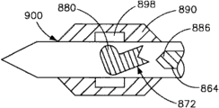
Figure 17 A is the amplification side perspective of two-way stitching thread by another embodiment of instrument, and this two-way stitching thread comprises the syringe needle with otch by instrument, and this otch is arranged to catch and the stitching thread strand is sent to the frame arm housing;
Figure 17 B is the sectional side view of the frame arm housing shown in Figure 17 A, and the expression syringe needle is in retracted position;
Figure 17 C is the sectional side view of the frame arm housing shown in Figure 17 B, and the expression syringe needle advances towards the frame arm housing;
Figure 17 D is the sectional side view of the frame arm housing shown in Figure 17 C, and the expression syringe needle fully advances in the frame arm housing;
Figure 17 E is the sectional side view of the frame arm housing shown in Figure 17 D, and the expression syringe needle is rotated into and makes the locking linking part of frame arm housing can catch the stitching thread strand;
Figure 18 A is the partial cross-sectional side-elevation view of two-way stitching thread by another embodiment of instrument, and this two-way stitching thread has configurable line retainer by instrument, is used to make the moving element of shuttle removably to be connected with syringe needle;
Figure 18 B is the partial cross-sectional side-elevation view of the instrument shown in Figure 18 A, and expression line retainer is in complete configuration status;
Figure 19 A is the partial cross-sectional side-elevation view of the instrument shown in Figure 18 A, and this instrument has shuttle to move element, and the moving element of this shuttle defines recess, and this recess is arranged to engage with the line retainer;
Figure 19 B is the partial cross-sectional side-elevation view of the instrument shown in Figure 19 A, and wherein, the line retainer disposes fully, and engages with the recess of the moving element of shuttle;
Figure 20 A as shown in Figure 18 A, have the partial cross-sectional side-elevation view of the two-way stitching thread of line retainer by instrument, the expression syringe needle is in retracted position;
Figure 20 B is the partial cross-sectional side-elevation view of the instrument shown in Figure 20 A, and the expression syringe needle is in complete progressive position, and wherein, the moving element of shuttle is contained in the frame arm housing;
Figure 20 C is the partial cross-sectional side-elevation view of the instrument shown in Figure 20 B, and the line retainer of expression syringe needle is withdrawn fully;
Figure 20 D is the partial cross-sectional side-elevation view of the instrument shown in Figure 20 C, and the expression syringe needle is in complete retracted position, and the moving element of shuttle is connected with the frame arm housing;
Figure 21 A is two-way stitching thread by the partial cross-sectional side-elevation view of another embodiment of instrument, and wherein, syringe needle comprises throws off pipe and wedge, but this wedge engage with the deflects finger that limits by the moving element of shuttle so that make shuttle move element and syringe needle disengagement;
Figure 21 B is the partial cross-sectional side-elevation view of the instrument shown in Figure 21 A, and the expression wedge is in complete progressive position;
Figure 21 C is the partial cross-sectional side-elevation view of the instrument shown in Figure 21 B, and expression is thrown off pipe and is in complete progressive position;
Figure 21 D is the partial cross-sectional side-elevation view of the instrument shown in Figure 21 C, and the expression syringe needle is in complete retracted position, and throws off with the moving element of shuttle;
Figure 21 E is the partial cross-sectional side-elevation view of the instrument shown in Figure 21 D, and the expression syringe needle advances towards the moving element of shuttle;
Figure 21 F is the partial cross-sectional side-elevation view of the instrument shown in Figure 21 E, and moving element of expression shuttle and syringe needle reconnect;
Figure 22 A is the partial cross-sectional side-elevation view of two-way stitching thread by another embodiment of instrument, and wherein, configurable ball retainer is used to make the moving element of shuttle removably to be connected with syringe needle;
Figure 22 B is the partial cross-sectional side-elevation view of the instrument shown in Figure 22 A, the configuration fully by wedge of expression ball retainer;
Figure 23 A is the partial cross-sectional side-elevation view of the instrument shown in Figure 22 A, and this instrument has shuttle to move element, and the moving element of this shuttle defines recess, and this recess is arranged to engage with the ball retainer;
Figure 23 B is the partial cross-sectional side-elevation view of the instrument shown in Figure 23 A, and expression ball retainer disposes fully by wedge, and engages with the recess of the moving element of shuttle;
Figure 24 A is the partial cross-sectional side-elevation view of two-way stitching thread by another embodiment of instrument, and wherein, the configurable line retainer with domed top and triangular base is used to make the moving element of shuttle removably to be connected with syringe needle;
Figure 24 B is the partial cross-sectional side-elevation view of the instrument shown in Figure 24 A, the configuration fully by wedge of expression ball retainer;
Figure 24 C is the partial cross-sectional side-elevation view of the instrument shown in Figure 24 A, and this instrument has shuttle to move element, and the moving element of this shuttle defines recess, and this recess is arranged to engage with the ball retainer;
Figure 24 D is the partial cross-sectional side-elevation view of the instrument shown in Figure 24 C, and expression ball retainer disposes fully by wedge, and engages with the recess of the moving element of shuttle;
Figure 25 A is the partial cross-sectional side-elevation view of two-way stitching thread by another embodiment of instrument, and wherein, configurable finger retainer is used to make the moving element of shuttle removably to be connected with syringe needle;
Figure 25 B is the partial cross-sectional side-elevation view of the instrument shown in Figure 25 A, the configuration fully by wedge of expression finger retainer;
Figure 26 A is the partial cross-sectional side-elevation view of the instrument shown in Figure 25 A, and this instrument has shuttle to move element, and the moving element of this shuttle defines recess, and this recess is arranged to engage with the finger retainer;
Figure 26 B is the partial cross-sectional side-elevation view of the instrument shown in Figure 26 A, and expression finger retainer disposes fully by wedge, and engages with the recess of the moving element of shuttle;
Figure 27 A is the partial cross-sectional side-elevation view of two-way stitching thread by another embodiment of instrument, and wherein, configurable scissor retainer is used to make the moving element of shuttle removably to be connected with syringe needle;
Figure 27 B is the partial cross-sectional side-elevation view of the instrument shown in Figure 27 A, the configuration fully by wedge of expression scissor retainer;
Figure 28 A is the partial cross-sectional side-elevation view of the instrument shown in Figure 27 A, and this instrument has shuttle to move element, and the moving element of this shuttle defines recess, and this recess is arranged to engage with the scissor retainer;
Figure 28 B is the partial cross-sectional side-elevation view of the instrument shown in Figure 28 A, and expression scissor retainer disposes fully by wedge, and engages with the recess of the moving element of shuttle;
Figure 29 A is the partial cross-sectional side-elevation view of two-way stitching thread by another embodiment of instrument, and wherein, configurable boot-shaped retainer is used to make the moving element of shuttle removably to be connected with syringe needle;
Figure 29 B is the partial cross-sectional side-elevation view of the instrument shown in Figure 29 A, the configuration fully by wedge of expression boot-shaped retainer;
Figure 30 A is the partial cross-sectional side-elevation view of the instrument shown in Figure 29 A, and this instrument has shuttle to move element, and the moving element of this shuttle defines recess, and this recess is arranged to engage with the boot-shaped retainer;
Figure 30 B is the partial cross-sectional side-elevation view of the instrument shown in Figure 30 A, and expression boot-shaped retainer disposes fully by wedge, and engages with the recess of the moving element of shuttle;
Figure 31 A is the partial cross-sectional side-elevation view of two-way stitching thread by another embodiment of instrument, and wherein, the rotation wing plate is used to make the moving element of shuttle removably to be connected with syringe needle;
Figure 31 B is the partial cross-sectional side-elevation view of the instrument shown in Figure 31 A, and expression rotation wing plate aligns with the slit that is limited by the moving element of shuttle;
Figure 31 C is the partial cross-sectional side-elevation view of the instrument shown in Figure 31 B, and expression rotation wing plate is configured, thereby makes the moving element of shuttle be connected with syringe needle;
Figure 32 A is the partial cross-sectional side-elevation view of two-way stitching thread by another embodiment of instrument, and wherein, inflatable needle tip is used to make the moving element of shuttle removably to be connected with syringe needle;
Figure 32 B is the partial cross-sectional side-elevation view of the instrument shown in Figure 32 A, represents that inflatable needle tip disposes by wedge, thereby makes the moving element of shuttle be connected with syringe needle;
Figure 33 A is the partial cross-sectional side-elevation view of two-way stitching thread by another embodiment of instrument, and wherein, inflatable sleeve is used to make the moving element of shuttle removably to be connected with syringe needle;
Figure 33 B is the partial cross-sectional side-elevation view of the instrument shown in Figure 33 A, and the expression inflatable sleeve disposes against the near-end of syringe needle head by promoting it, thereby makes the moving element of shuttle be connected with syringe needle;
Figure 34 A is the partial cross-sectional side-elevation view of two-way stitching thread by another embodiment of instrument, and wherein, optionally inflatable sleeve is used to make the moving element of shuttle removably to be connected with syringe needle;
Figure 34 B is the partial cross-sectional side-elevation view of the instrument shown in Figure 34 A, and the expression inflatable sleeve disposes along the needle shaft withdrawal by making it, thereby makes the moving element of shuttle be connected with syringe needle;
Figure 34 C is the partial cross-sectional side-elevation view of two-way stitching thread by another embodiment of instrument, and wherein, the optional inflatable sleeve with expanded radially projection is used to make the moving element of shuttle removably to be connected with syringe needle;
Figure 34 D is the partial cross-sectional side-elevation view of the instrument shown in Figure 34 C, represents that expandable sleeve disposes along the needle shaft withdrawal by making it, thereby makes the moving element of shuttle be connected with syringe needle;
Figure 35 A is the partial cross-sectional side-elevation view of two-way stitching thread by another embodiment of instrument, and wherein, inflatable split ring is used to make the moving element of shuttle removably to be connected with syringe needle;
Figure 35 B is the partial cross-sectional side-elevation view of the instrument shown in Figure 35 A, represents that inflatable split ring disposes by wedge, thereby makes the moving element of shuttle be connected with syringe needle;
Figure 36 A is the partial cross-sectional side-elevation view of two-way stitching thread by another embodiment of instrument, and wherein, inflatable cage is used to make the moving element of shuttle removably to be connected with syringe needle;
Figure 36 B is the partial cross-sectional side-elevation view of the instrument shown in Figure 36 A, represents that inflatable cage by being disposed by the sleeve compresses cage, is connected with syringe needle thereby make shuttle move element;
Figure 37 A is the partial cross-sectional side-elevation view of two-way stitching thread by another embodiment of instrument, wherein, has the inflatable cage that radially extends projection and is used to make the moving element of shuttle removably to be connected with syringe needle;
Figure 37 B is the partial cross-sectional side-elevation view of the instrument shown in Figure 37 A, represents that inflatable cage by being disposed by the sleeve compresses cage, is connected with syringe needle thereby make shuttle move element;
Figure 38 A is the partial cross-sectional side-elevation view of two-way stitching thread by another embodiment of instrument, and wherein, the cage with expandable part is used to make the moving element of shuttle removably to be connected with syringe needle;
Figure 38 B is the partial cross-sectional side-elevation view of the instrument shown in Figure 38 A, and the expandable part of expression cage is connected with syringe needle thereby make shuttle move element by being disposed by the sleeve compresses cage;
Figure 39 A is the partial cross-sectional side-elevation view of two-way stitching thread by another embodiment of instrument, and wherein, oval syringe needle head is used to make the moving element of shuttle removably to be connected with syringe needle;
Figure 39 B is the partial cross-sectional side-elevation view of the instrument shown in Figure 39 A, represents that oval syringe needle head revolves to turn 90 degrees by syringe needle to dispose, thereby makes the moving element of shuttle be connected with syringe needle;
Figure 40 A is the partial cross-sectional side-elevation view of two-way stitching thread by another embodiment of instrument, and wherein, the cross member of load on spring is used for the moving element of shuttle is remained on the frame arm housing;
Figure 40 B is the partial cross-sectional side-elevation view of the instrument shown in Figure 40 A, and the proximal of the moving element of expression cross member and shuttle engages, thereby makes shuttle move the element connection and remain in the frame arm housing;
Figure 41 A is the partial cross-sectional side-elevation view of the instrument shown in Figure 40 A, wherein, the transverse beam of load on spring be arranged to be formed at the moving element of shuttle in recess engage;
Figure 41 B is the partial cross-sectional side-elevation view of the instrument shown in Figure 41 A, and the expression beam engages with the recess of the moving element of shuttle;
Figure 42 A is the partial cross-sectional side-elevation view of two-way stitching thread by another embodiment of instrument, and wherein, the flexible polymer pipe is used for the moving element of shuttle is remained on the frame arm housing;
Figure 42 B is the partial cross-sectional side-elevation view of the instrument shown in Figure 42 A, and the proximal of the moving element of expression flexible pipe and shuttle engages, thereby makes shuttle move the element connection and remain in the frame arm housing;
Figure 43 A is the partial cross-sectional side-elevation view of the instrument shown in Figure 42 A, expression flexible polymer property management be arranged to be formed at the moving element of shuttle in recess engage;
Figure 43 B is the partial cross-sectional side-elevation view of the instrument shown in Figure 43 A, and the expression pipe engages with the recess of the moving element of shuttle;
Figure 44 A is the partial cross-sectional side-elevation view of two-way stitching thread by another embodiment of instrument, and wherein, C clamp is used for the moving element of shuttle is remained on the frame arm housing;
Figure 44 B is the partial cross-sectional side-elevation view of the instrument shown in Figure 44 A, and the proximal of the moving element of expression C clamp and shuttle engages, thereby makes shuttle move the element connection and remain in the frame arm housing;
Figure 44 C is the front view of the C clamp shown in Figure 44 A, and this C clamp is in not clamped position;
Figure 44 D is the front view of the C clamp shown in Figure 44 A, and this C clamp is in clamped position;
Figure 45 A is the partial cross-sectional side-elevation view of the instrument shown in Figure 44 A, wherein, C clamp be arranged to be formed at the moving element of shuttle in recess engage;
Figure 45 B is the partial cross-sectional side-elevation view of the instrument shown in Figure 45 A, and the expression C clamp engages with the recess of the moving element of shuttle;
Figure 46 A is the partial cross-sectional side-elevation view of two-way stitching thread by another embodiment of instrument, and wherein, sheet spring finger is used for the moving element of shuttle is remained on the frame arm housing;
Figure 46 B is the partial cross-sectional side-elevation view of the instrument shown in Figure 46 A, and expression sheet spring finger engages with the proximal of the moving element of shuttle, thereby makes shuttle move the element connection and remain in the frame arm housing;
Figure 47 A is the partial cross-sectional side-elevation view of the instrument shown in Figure 46 A, wherein, sheet spring finger be arranged to be formed at the moving element of shuttle in recess engage;
Figure 47 B is the partial cross-sectional side-elevation view of the instrument shown in Figure 47 A, and the expression finger engages with the recess of the moving element of shuttle;
Figure 48 A is the partial cross-sectional side-elevation view of two-way stitching thread by another embodiment of instrument, and wherein, line support member (buttress) is used for the moving element of shuttle is remained on the frame arm housing;
Figure 48 B is the partial cross-sectional side-elevation view of the instrument shown in Figure 48 A, and expression line support member engages with the proximal of the moving element of shuttle, thereby makes shuttle move the element connection and remain in the frame arm housing;
Figure 49 A is the partial cross-sectional side-elevation view of the instrument shown in Figure 48 A, wherein, the line support member be arranged to be formed at the moving element of shuttle in recess engage;
Figure 49 B is the partial cross-sectional side-elevation view of the instrument shown in Figure 49 A, and expression line support member engages with the recess of the moving element of shuttle;
Figure 50 A is the partial cross-sectional side-elevation view of two-way stitching thread by another embodiment of instrument, and wherein, the door of load on spring is used for the moving element of shuttle is remained on the frame arm housing;
Figure 50 B is the partial cross-sectional side-elevation view of the instrument shown in Figure 50 A, and wherein, the door of load on spring is arranged to engage with the near-end of the moving element of shuttle;
Figure 51 A is the partial top view of two-way stitching thread by another embodiment of instrument, and wherein, series of grooves is used to make the moving element of syringe needle and shuttle removably to be connected with catcher and makes the moving element of shuttle removably be connected with the frame arm housing;
Figure 51 B is the partial top view of the instrument shown in Figure 51 A, and the moving element of expression syringe needle and shuttle engages with the frame arm housing;
Figure 51 C is the perspective view that moves element with the shuttle that the instrument shown in Figure 51 A uses;
Figure 51 D is the front view of the moving element of the shuttle shown in Figure 51 C;
Figure 51 E is the side view of the moving element of the shuttle shown in Figure 51 C;
Figure 52 A is the partial side view of two-way stitching thread by another embodiment of instrument, and wherein, characteristic threads is used to make the moving element of syringe needle and shuttle removably to be connected and makes the moving element of shuttle removably be connected with the frame arm housing;
Figure 52 B is the local upwarding cutaway view of the instrument shown in Figure 52 A, and the expression syringe needle is in complete progressive position;
Figure 52 C is the fragmentary, perspective view of the instrument shown in Figure 52 A, and the moving element of expression syringe needle and shuttle is in complete retracted position;
Figure 52 D is the fragmentary, perspective view of the instrument shown in Figure 52 C, and the expression syringe needle advances in the frame arm housing;
Figure 52 E is the fragmentary, perspective view of the instrument shown in Figure 52 D, and the moving element of expression syringe needle and shuttle is rotated, thereby selectively makes the moving element of shuttle be connected with the frame arm housing;
Figure 52 F is the fragmentary, perspective view of the instrument shown in Figure 52 E, and the expression syringe needle is further rotated, so that make syringe needle and the moving element of shuttle throw off;
Figure 52 G is the fragmentary, perspective view of the instrument shown in Figure 52 F, the withdrawal of expression syringe needle, and the moving element of shuttle keeps being connected with the frame arm housing simultaneously;
Figure 52 H is the fragmentary, perspective view of the instrument shown in Figure 52 G, and the expression syringe needle is in complete retracted position;
Figure 52 I is the fragmentary, perspective view of the instrument shown in Figure 52 H, and the expression syringe needle advances in the frame arm housing;
Figure 52 J is the fragmentary, perspective view of the instrument shown in Figure 52 I, and the expression syringe needle is rotated, thereby makes the moving element of syringe needle and shuttle be connected;
Figure 52 K is the fragmentary, perspective view of the instrument shown in Figure 52 J, and the moving element of expression syringe needle and shuttle is rotated, thereby makes moving element of shuttle and frame arm housing throw off;
Figure 52 L is the fragmentary, perspective view of the instrument shown in Figure 52 K, and the moving element of expression syringe needle and shuttle is withdrawn from the frame arm housing;
Figure 53 A is the partial sectional view of two-way stitching thread by another embodiment of instrument, and wherein, syringe needle has external screw thread, and the moving element of shuttle has female thread, so that make the moving element of syringe needle and shuttle removably be connected;
Figure 53 B is the partial sectional view of the instrument shown in Figure 53 A, and the moving element of expression syringe needle and shuttle is in complete progressive position;
Figure 53 C is the partial sectional view of the instrument shown in Figure 53 B, and the expression syringe needle is in complete retracted position, and the moving element of shuttle is connected with the frame arm housing;
Figure 54 A is the vertical view with syringe needle of wing plate;
Figure 54 B is the left side view of the syringe needle shown in Figure 54 A;
Figure 54 C is a vertical view of being arranged to the moving element of the shuttle that removably is connected with the syringe needle shown in Figure 54 A;
Figure 54 D is the left side view of the moving element of the shuttle shown in Figure 54 C;
Figure 54 E is the rearview of the moving element of the shuttle shown in Figure 54 D;
Figure 54 F is the vertical view that is configured to receive the frame arm housing of the moving element of the shuttle shown in Figure 54 C;
Figure 54 G is the left side view of the frame arm housing shown in Figure 54 F;
Figure 54 H is the rearview of the frame arm housing shown in Figure 54 G;
Figure 54 I is the partial top view of the instrument shown in Figure 54 A-54H, and the moving element of expression syringe needle and shuttle is in complete retracted position;
Figure 54 J is the partial top view of the instrument shown in Figure 54 I, and the moving element of expression syringe needle and shuttle advances in the frame arm housing;
Figure 54 K is the partial top view of the instrument shown in Figure 54 J, and the moving element of expression syringe needle and shuttle is rotated, thereby selectively makes the moving element of shuttle be connected with the frame arm housing;
Figure 54 L is the partial top view of the instrument shown in Figure 54 K, the withdrawal of expression syringe needle, and the moving element of shuttle keeps being connected with the frame arm housing simultaneously;
Figure 54 M is the partial top view of the instrument shown in Figure 54 L, and the expression syringe needle advances in the moving element of shuttle;
Figure 54 N is the partial top view of the instrument shown in Figure 54 M, and the moving element of expression syringe needle and shuttle is rotated, so that make moving element of shuttle and frame arm housing throw off;
Figure 55 is two-way stitching thread by the perspective view of another embodiment of instrument, this two-way stitching thread by the instrument class shown in instrument and Figure 54 A-54N seemingly, except the inverted configuration of qualification engagement features on syringe needle and the moving element of shuttle;
Figure 56 A is the side perspective of two-way stitching thread by another embodiment of instrument, represents operable supplementary features;
Figure 56 B is the elevational perspective view of the driver that can use with the instrument shown in Figure 56 A;
Figure 56 C is the side perspective that can move element with the shuttle that the instrument shown in Figure 56 A uses;
Figure 56 D is the rear perspective of the frame arm that can use with the instrument shown in Figure 56 A;
Figure 57 A is the side view of two-way stitching thread by another embodiment of instrument, is arranged in and produces path in the bone structure, and stitching thread can pass through this path;
Figure 57 B is the side view of the instrument shown in Figure 57 A, and this instrument has collision bar;
Figure 57 C is the side view of the instrument shown in Figure 57 A, and this instrument has the collision bar of being arranged to catch syringe needle;
Figure 57 D is the front view of the anchor clamps that are associated with the collision bar shown in Figure 57 C;
Figure 57 E is the front views in the closed position of the anchor clamps shown in Figure 57 D;
Figure 58 A is the side view of simple suture;
Figure 58 B is the side view of horizontal box-like cotton-padded mattress formula suture;
Figure 58 C is the side view of horizontal cotton-padded mattress formula suture;
Figure 58 D is the side view of reverse horizontal cotton-padded mattress formula suture;
Figure 58 E is the side view of vertical cotton-padded mattress formula suture;
Figure 58 F is the side view of oppositely vertical cotton-padded mattress formula suture; And
Figure 58 G-58I is the side view that is used near the sewing method of the soft tissue repair the bone element.
The specific embodiment
Some term that uses in the following description is for convenience, rather than limits.Direction among the figure of word " right side ", " left side ", the reference of " bottom " and " top " expression institute.Word " inboard " or " distally " and " outside " or " nearside " be meant respectively towards with away from patient body or stitching thread direction by the geometric center of device instrument and its associated components.Word " front ", " back ", " top ", " following " and correlation word and/or phrase are meant the optimum position and the orientation of the human body of institute's reference, rather than limit.Term comprises the speech of above-mentioned word, derivative words and the similar meaning.
With reference to figure 1A-1C, two-way stitching thread passes through instrument 10 L extension along the longitudinal direction, and comprises near-end P and far-end D.As shown in the figure, instrument 10 comprises handle 14, the slender body 18 that is connected with this handle 14 and the frame arm 22 that is connected with the far-end of this slender body 18.Frame arm 22 comprises arm 190, and this arm 190 is connected with the far-end of slender body 18, and support framework arm housing 198, receives gap 202 so that limit tissue between slender body 18 and frame arm housing 198.Instrument 10 also comprises: actuator element 26; Syringe needle 34, this syringe needle 34 is connected with the far-end of actuator element 26; And handle 30, this handle 30 is connected with the near-end of actuator element 26.Actuator element 26 and syringe needle 34 can be at handle 14 inner and slender body 18 inside in withdrawal (rear portion) position with stretch out or the reciprocal translation between (front portion) position of advancing.Instrument 10 also comprises: syringe needle shape shuttle moves element 40, and the moving element 40 of this shuttle is arranged to carry one stitching thread, inserts so that pass tissue defects; And frame arm housing 198.Described in more detail as the back, when the moving element 40 of shuttle was connected with syringe needle 34, the moving element 40 of shuttle can pass tissue defects.In case the moving element 40 of shuttle passes tissue defects, the moving element 40 of shuttle just can removably be connected with frame arm housing 198.
Shown in Figure 1A-1B and 2A-2H, handle 14 comprises body 50, and this body 50 has the handle 54 that extends from the lower surface of body 50 downwards.Body 50 is elongated and rectangular shape roughly.As shown in Fig. 2 D, the hole 58 of first size L is along the longitudinal direction passed the hole 62 that body 50 distad extends to second size from the near-end of body 50.Second hole 62 continues distad to extend in the hole 66 of the 3rd size, and the remote extension of body 50 is passed in the hole of the 3rd size.Each hole 58,62,66 is sized to hold the specific part of instrument 10.For example, actuator element 26 can translation in hole 58, and syringe needle 34 can translation in hole 62, and body part 18 is fixed in the hole 66.
According to illustrated embodiment, first hole 58 is a substantial cylindrical, and can receive actuator element 26, as shown in Figure 1B.Particularly, actuator element 26 can back and forth translation in first hole 58.With reference to figure 2D and 2H, the 4th hole 70 extends through the basal surface of body 50 transverse to longitudinal direction L and stretches in first hole 58.As shown in the figure, the 4th hole 70 comprises fit structure, and for example the bulb plunger 74, and this bulb plunger 74 is suitable for engaging with actuator element 26 directly or indirectly.
Shown in Fig. 3 A-3D, actuator element 26 comprises cylindrical body 76, and this cylindrical body 76 has at first Connection Element 78 of its far-end with at its second Connection Element 82 of proximal end.The body 76 of actuator element 26 defines mating feature, and locating slot (detent) 86 for example, this locating slot 86 are arranged to and the bump bonds of stretching out from locking piece.First Connection Element 78 is arranged to actuator element 26 is attached on the syringe needle 34, and second Connection Element 82 is arranged to actuator element 26 is attached on the thumb rings 30.Therefore, when actuator element 78 during by user's translation, syringe needle 34 is with translation.
As shown in Fig. 4 A-4C, handle 30 can be the thumb rings that comprises body 98, and this body 98 has proximad to stretch into hole 102 in the body 98.Hole 102 is suitable for receiving second Connection Element 82 of actuator element 26.Body 98 defines ring 106, and this ring 106 can receive user's opposing thumb, makes the user to apply power to thumb rings 30 at an easy rate, thereby makes actuator element 26 and 34 translations forward or backward of (therefore) syringe needle.
In order to limit the stroke of actuator element 26 and syringe needle 34, stitching thread comprises actuator retainer 110 by device 10.As shown in Figure 1B and 5A-5C, actuator retainer 110 is the substantial cylindrical body 114 in second hole 62 that is arranged in handle 14.As shown in Fig. 5 A-5C, the body 114 of actuator retainer 110 comprises erose hole 118, is used for receiving and being attached at syringe needle 34.The irregularly shaped Any shape that means, except ideal cylindrical.
The body 114 of actuator retainer 110 also defines two fit structures, for example is formed at the locating slot 122 in its outer surface, is used for receiving the corresponding fit structure that can be arranged in handle 14, for example the bulb plunger.As shown in the figure, locating slot 122 is with respect to the longitudinal axis of actuator retainer 110 90 degree radially separated from one another.For the embodiment of the instrument 10 that needs syringe needle 34 rotations, locating slot 122 is configured to receive the bulb plunger 126 that is arranged in the handle 14, so that the rotation of restriction or control syringe needle 34.Therefore, the rotation of syringe needle 34 is limited in 90 degree.Should be known in that actuator retainer 110 is not limited to such design, it is contemplated that other design.For example, actuator retainer 110 can be implemented by making second hole 62 of handle 14 narrow down.Narrowed portion near the coupling part of actuator 26 and syringe needle 34, contact when in this case, will be arranged in actuator 26 with respect to handle 14 translation set-points with the far-end of actuator element 26.
Stitching thread can comprise locking piece 130 by device 10, and this locking piece 130 can be operable to the lengthwise position of fixing actuator 26 and (therefore) syringe needle 34, makes that actuator 26 and syringe needle 34 no longer can translations when locking.Locking piece 130 comprises: locking member 134, as shown in Figure 6A and 6B; And locking cap 138, as shown in Figure 7A and 7B, this locking cap 138 interacts with locking member 134, so that the position of fixedly locked element 134.With reference to figure 6A and 6B, locking member 134 comprises head 142 and the body 146 that stretches out from this head 142.Body 146 defines two bigger locating slots 148, three less locating slots 150 and stretches into hole 152 in the end of body 146.Body also defines the projection 153 of extending between two big locating slots 148.When locking member 134 is located such that actuator is received in the big locating slot 148, the bulb plunger 74 that is included in the 4th hole 70 of handle will engage with a less locating slot 150 in outside, and actuator 26 can be forward and translation backward.But, when the bulb plunger 74 in the 4th hole 70 that is included in handle engages with the less locating slot 150 in center, locking member 134 is located such that projection 153 engages with the locating slot 86 of actuator 26, and actuator 26 can not move, so with actuator 26 and syringe needle 34 locks in place.
Locking cap 138 is arranged to engage with the hole 152 of locking member 134.As shown in Figure 7A and 7B, locking cap 138 comprises head 154 and the body 156 that stretches out from this head 154.Body 156 is cylindrical, and is arranged to engage with the hole 152 of locking member 134.When the body 156 of locking cap 138 engages with the hole 152 of locking member 134, the position of locking member will be fixed.
As shown in Figure 1A and 8A-8D, body part 18 is vertically elongated, and defines the conduit 160 that longitudinal extension passes the whole length of body part 18.As shown in Figure 1B, syringe needle 34 can translation in the conduit 160 of body part 18.Conduit 160 comprises first conduit part and the second conduit part 164, and this second conduit part 164 is arranged in the distally of first conduit part, and has than the bigger diameter of first conduit part.The size of conduit 160 can be arranged to hold syringe needle 34, makes syringe needle 34 to move back and forth between (front portion) position and withdrawal (rear portion) position stretching out or advance.Preferably, the second conduit part 164 has than the bigger diameter of first conduit part.Therefore, the second bigger conduit part 164 can receive the moving element 40 of shuttle when syringe needle 34 is in retracted position, thereby with acting on the sheath that syringe needle and shuttle move element.
As shown in Figure 1A, 8A-8B and 9A-9D, body part 18 also defines actuator slit 168, and this actuator slit 168 extends through outer surface along the direction of roughly crossing conduit 160.Actuator slit 168 stretches in first conduit part of conduit 160 in the proximal end of body part 18.Stitching thread comprises most advanced and sophisticated actuator 180 by instrument 10, and this tip actuator 180 is arranged to drive syringe needle 34, thereby makes the moving element 40 of shuttle be connected or throw off with syringe needle 34.As shown in Figure 1A and 9A-9D, most advanced and sophisticated actuator 180 extends through actuator slit 168, and is attached on the syringe needle 34.Particularly, most advanced and sophisticated actuator 180 comprises keyhole 188, and this keyhole 188 receives syringe needle 34 at certain position, so syringe needle 34 comprises similar key tee section, makes most advanced and sophisticated actuator 180 rotatably be connected with main syringe needle 34.Most advanced and sophisticated actuator 180 is protruding from body part 18, and can be engaged by the user, so that make syringe needle 34 revolve the angular range that turn 90 degrees around the longitudinal axes L of instrument 10 between latched position and lockset position of coupler.When in latched position, the moving element 40 of shuttle is connected with frame arm housing 198.When at lockset position of coupler, the moving element 40 of shuttle is thrown off with frame arm housing 198.Most advanced and sophisticated actuator 180 also comprises the labelling 189 of indicating tip position.This labelling can illustrate " unblanking in the tip " (as shown in Fig. 9 C) or " most advanced and sophisticated locking " (as shown in Fig. 9 D).But should be known in other embodiment of instrument 10 translation that the moving element 40 of shuttle can be by connected structure or other similar structures or actuate (different) and removably be connected with frame arm housing 198 with the rotation of most advanced and sophisticated actuator 180.Therefore, should be known in that most advanced and sophisticated actuator 180 can also be arranged to make connected structure or other similar structures translation.
As shown in Figure 1A-1B and 10A-10H, frame arm 22 is stretched out from slender body 18.Particularly, frame arm 22 comprises arm 190, and this arm 190 is connected with the far-end of slender body parts 18, and distad extends to frame arm housing 198.Frame arm housing 198 stretches out from the far-end approximate vertical of frame arm 22, and is configured to receive the moving element 40 of shuttle.Therefore we can say that frame arm 22 comprises the frame arm housing 198 of the far-end that is bearing in frame arm 22.Tissue receives gap 202 and is arranged between the far-end of frame arm housing 198 and slender body 18.Tissue reception gap 202 is configured to receive has a for example block organization of breach of tissue defects, and this tissue defects will be repaired by sewing up instrument 10.
As shown in Figure 11 A-11E, main syringe needle 34 comprises elongate rod 230 and the syringe needle element 234 that stretches out from the far-end of this bar 230.As shown in Figure 11 A-B, bar 230 is a substantial cylindrical, and comprises key shape part 238, and the shape of this key shape part 238 is corresponding with the keyhole 188 of most advanced and sophisticated actuator 180.The key shape part 238 of bar 230 is alignd with actuator slit 168.Therefore, key shape part 238 is arranged in actuator retainer 110 and the position that most advanced and sophisticated actuator 180 is connected with main syringe needle 34, and the keyhole 188 that therefore passes most advanced and sophisticated actuator 180 extends.Therefore, when most advanced and sophisticated actuator 180 is rotated by the user, syringe needle 34 also will rotate in the above described manner.Syringe needle 34 also comprises Connection Element 242, and this Connection Element 242 extends back from bar 230, and is arranged to actuator element 26 is attached on the main syringe needle 34.Connection Element 242 can be to allow hexagon or the head part of syringe needle 34 with respect to actuator element 26 rotations.Therefore, syringe needle 34 can rotate, and actuator element keeps static simultaneously.
As shown in Figure 11 D and 11E, syringe needle element 234 comprises cylindrical body 246, and this cylindrical body 246 has needle tip 250 and connected structure 252, and this connected structure 252 is limited by two fins 254 that extend radially outwardly from cylindrical body 246.Each fin 254 comprises angled front 258 and inclined rear face 262. Inclined surface 258 and 262 makes fin 254 and (therefore) syringe needle element 234 can more easily engage and snap in the moving element 40 of shuttle and breaks away from the moving element 40 of shuttle.
As shown in Figure 12 A-12E, the moving element 40 of shuttle comprises syringe needle bonding part 300 and the tissue engagement portion 304 of extending previously in syringe needle bonding part 300.Syringe needle bonding part 300 is arranged to be connected with the syringe needle element 234 of syringe needle 34.According to illustrated embodiment, syringe needle bonding part 300 defines hole 308, and this hole 308 is configured to receive the syringe needle element 234 of syringe needle 34.Groove 312 is formed in the syringe needle bonding part 300, and stretches in the hole 308.Groove 312 forms connected structure 314, and this connected structure 314 is corresponding with the connected structure 252 of syringe needle 34.Therefore, groove 312 is configured to receive the fin 254 of syringe needle 34, thereby makes the moving element 40 of syringe needle 34 and shuttle removably be connected.Hole 316 is used for firmly keeping sutural end in the front of groove 312.Two-way stitching thread instrument 10 can assembled in advance be fixed on the stitching thread on the moving element 40 of shuttle, and perhaps instrument 10 can provide a plurality of shuttles moving element 40, and the moving element 40 of each shuttle has one stitching thread that is fixed on above it.
In order to make the stitching thread strand keep stretching, stitching thread instrument 10 can comprise the stitching thread stretcher 350 that is connected with handle 14.As shown in Figure 1A and 13, stitching thread stretcher 350 can be arranged to keep and the fixing lax end of suture material, and in the stitching thread strand, keep stretching, thereby make the stitching thread strand can under extended state, be pulled through stitching thread stretcher element 350.Stitching thread stretcher 350 is arranged to suture material is kept and is fixed on each side of handle 14, and can arrange by handle 14, perhaps can implement a side that is arranged in handle 14 by two stitching thread stretcher elements 350.Stretcher 350 comprises two slits, a side at handle 14, and the stitching thread strand passes one in two slits, so that make strand keep stretching.
In operation, operator are bonded on the syringe needle 34 by making the fin 254 of syringe needle snap in to make the shuttle that is attached with the stitching thread strand move elements 40 in the groove 312 of the moving element 40 of shuttle, and selectively make stitching thread be arranged through stitching thread stretcher 250, as shown in Figure 14 A.Then, operator catch handle 14 with forefinger and middle finger, and thumb is arranged through thumb rings 30, and wherein, actuator 26 is from the position of handle 14 proximads withdrawal.The tissue that comprises tissue defects (for example passing the crack of the annulus fibrosis of intervertebral disc) is received in the tissue reception gap 202 that is arranged between frame arm housing 198 and the body part 18.Be in the driving of thumb ring lock 130 by thumb rings locking cap 138 and open or when unblanking structure, thumb rings 30 is with respect to distad translation of handle 14, thereby make actuator 26 and syringe needle 34 distad advance with respect to handle 14, and make the far-end of syringe needle 34 and the stitching thread that is attached at the moving element 40 of shuttle on this syringe needle and be attached on the moving element 40 of shuttle pass near the tissue of defective, and force formation contact between the far-end of moving element 40 of shuttle and frame arm 22, as shown in Figure 14 C.Then, drive most advanced and sophisticated actuator 180, make syringe needle 34 revolve and turn 90 degrees, thereby make the locking mechanism 320 of the moving element 40 of shuttle engage, as shown in Figure 14 E with the locking linking part 214 of frame arm housing 198.
When syringe needle 34 withdrawal, the moving element 40 of shuttle will discharge from syringe needle 34, and maintenance selectively is connected with frame arm housing 198, thereby the maintenance shuttle moves element 40, and the stitching thread strand is connected near the defective the bottom side of organizing.Then, syringe needle 34 is retracted in the protection sheath that is formed by body part 18, as shown in Figure 14 G.Then, frame arm 22 is handled (for example rotation) near another zone on the bottom side of organizing the defective under the situation that syringe needle 34 safety is covered, for example in the relative bottom side of defective, in case reorientate best, syringe needle 34 utilizes thumb rings 30 and again with respect to distad translation of handle 14, and thumb ring lock 130 and thumb rings locking cap 134 remained on lockset position of coupler, thereby force near second position of syringe needle 34 defective to pass through to the bottom side of tissue from the top side, and make the far-end of syringe needle 34 engage again or block and be back in the moving element 40 of shuttle, as shown in Figure 14 K.Then, most advanced and sophisticated actuator 180 drives again or revolves along the direction of rotation opposite with first driving of most advanced and sophisticated actuator 198 and turn 90 degrees, thereby makes the moving element 40 of shuttle unclamp from frame arm housing 198.Then, thumb rings 30 is withdrawn with respect to handle 14 proximads, thereby make actuator 26 and syringe needle 34 corresponding withdrawals, and therefore make syringe needle 34 far-end and have the moving element 40 of sutural shuttle and throw off with frame arm 22, and pass outwards through near the top side of the tissue the defective near the bottom side of the tissue the defective, as shown in Figure 14 M.According to the size of defective and the feature of tissue, these steps can repeat one or many when needed.
In another embodiment, with reference to Figure 15, can use the ring-type shuttle to move element.As shown in Figure 15, two-way stitching thread can comprise that by instrument 10 the ring-type shuttle moves element 300, and the moving element 300 of this ring-type shuttle is clasped above being arranged in syringe needle 308.As shown in the figure, syringe needle 308 comprises the syringe needle element 312 that stretches out from bar 316.Syringe needle 308 also comprises for example rib 320 of the connected structure that forms around the far-end of bar 316.The part of syringe needle element 312 and bar 316 part is at least passed the moving element 300 of shuttle and back and forth translation.Releasing tube 322 arranges that around bar 316 this releasing tube 322 has the inclination composition surface 323 at its far-end.Pipe 322 is arranged to slide along bar 316, so that make the inclined surface 323 of pipe 322 contact with the moving element 300 of shuttle, throws off with syringe needle 308 thereby help the moving element 300 of shuttle.
The moving element 300 of shuttle comprises annular body 324, and this annular body 324 has passes the hole 328 that body 324 extends.Stitching thread strand 326 is attached on the body 324.Body 324 comprises the groove 330 in the inner surface that is formed at hole 328, and this groove 330 defines and the corresponding connected structure of the connected structure of syringe needle 308.Preferably, body 324 has the spring-like feature, so that can expand along diametric(al).The expanded radially of body 324 will make connected structure to be bonded with each other at an easy rate and to throw off.Body 324 comprises that also locking mechanism for example is formed at the groove 342 in the outer surface of body 324.This groove 342 makes the moving element of shuttle selectively to be connected with the frame arm housing of frame arm, for example the frame arm housing 350 shown in Figure 15.
As shown in the figure, frame arm housing 350 comprises opening 354, and this opening 354 provides the import of leading to chamber 358.Chamber 358 is a convergent, and is configured to receive moving element 300 of shuttle and syringe needle 308.Chamber 358 comprises locking linking part 362, and this locking linking part 362 is corresponding with the locking mechanism 338 on being formed at the moving element 300 of shuttle.As shown in the figure, locking linking part 362 comprises that the maintenance packing ring 366 of load on spring, this maintenance packing ring 366 are contained in the maintenance groove in the inner surface that is formed at chamber 358.The packing ring 366 of load on spring is arranged to engage with groove 342 in the body 324 that is formed at the moving element 300 of shuttle.In order to help the moving element 300 of shuttle to throw off from frame arm housing 350, chamber 358 is included in the conical releasing device 370 of its far-end, so that make the moving element 300 of shuttle can outwards eject and engage again with syringe needle 308.
In operation, syringe needle 308, the moving element 300 of shuttle, outside releasing tube 322 and stitching thread 326 pass tissue by the actuator of actuating instrument from first side direction, second side.Then, the moving element 300 of shuttle receives in the frame arm housing 350 in second side of tissue, the moving element 300 of shuttle is locked in the frame arm housing 350 by being clasped between the locking groove 342 on keeping the moving element 300 of packing ring 366 and shuttle, thereby stitching thread is positioned on second side of tissue.Being clasped between moving element 300 of shuttle and syringe needle 308 preferably by when syringe needle 308 is withdrawn a little, keeping original position to discharge the moving element 300 of shuttle by outside releasing tube 322.In case the release that is clasped between moving element 300 of shuttle and syringe needle 308, syringe needle 308 and outside releasing tube 322 further are retracted at the retracted position of stitching thread by the inside, hole of the body part of device instrument 100, and outside releasing tube 322 further is retracted to its initial position with respect to syringe needle 308.Then, frame arm can move to another zone of second side of tissue.In case reorientate, syringe needle 308 and outside releasing tube 322 are actuated and pass tissue from first side direction, second side, and in second side, syringe needle 308 moves element 300 with shuttle again by being clasped and engages.Then, syringe needle 308, the moving element 300 of shuttle, outside releasing tube 322 and stitching thread 326 are withdrawn fully, thereby the moving element of shuttle is discharged the snap fit engagement of frame arm housing 350 from it, and therefore stitching thread are taken back to first tissue sides from second tissue sides.
In another embodiment, with reference to figure 16A and 16B, can use the wire suture loop to replace shuttle to move element.As shown in Figure 16 A, two-way stitching thread can comprise the wire suture loop 400 with shape memory characteristics by instrument 10, rather than can be captured in the moving element of shuttle in the frame arm housing (for example the frame arm housing 404) of frame arm.As shown in the figure, suture loop 400 can be arranged around syringe needle 408.When suture loop 400 was arranged around syringe needle 408, tensile force was applied on the ring 400, makes it can remain on the syringe needle 408.Suture loop 400 is load on spring preferably, makes it can catch and remain in the maintenance groove or groove 412 that is formed in the frame arm housing 404.Load on spring for example can provide by comprising Nitinol owing to the line that has shape memory, is connected with sutural far-end produces.Like this, suture loop and syringe needle can be thought connected structure.
In another embodiment, with reference to figure 17A-17E, two-way stitching thread can comprise syringe needle 450 by instrument 10, and this syringe needle 450 has is arranged to catch and carries one sutural otch 454.Has sutural syringe needle 450 by making thumb rings and advance or driving simple trigger mechanism and pass tissue from first side direction, second side.Syringe needle 450 deflection by the finger 456 of stretching out from frame arm housing 460, then, stitching thread is received and is captured in the frame arm 460 at second side joint of tissue.Then, syringe needle 450 is retracted in the protection sheath, and stitching thread remains on second side of tissue simultaneously.In order to catch stitching thread again, syringe needle 450 advances in the frame arm housing 460, then rotation.When syringe needle 450 withdrawals, stitching thread will be caught again by otch 454.
In another embodiment, with reference to figure 18A and 18B, two-way stitching thread can comprise syringe needle 500 and configurable line retainer 504 by instrument 10, and this line retainer 504 can translation in the conduit 508 of syringe needle 500.As shown in the figure, conduit 508 passes the center of syringe needle 500 and extends, and ends at opening 512 places of nearside of the far-end of syringe needle 500.Configurable line retainer 504 can translation between extended position (as shown in Figure 18 B) and retracted position (as shown in Figure 18 A) in conduit 508.When line retainer 504 is in extended position, line retainer 504 leaves opening 512, so that provide, thereby the moving element 516 of shuttle caught online retainer 504 and be formed between the support member 520 on the upper surface of syringe needle 500 against the support member of the front end of the moving element 516 of tubulose shuttle (the moving element 516 of this tubulose shuttle is arranged around syringe needle 500).Support member 520 can be the ring that extends around syringe needle 500 fully, perhaps even single globule.Also can select, line retainer 504 can stretch in the recess 524 in the inner surface in the hole 528 that is formed at the moving element 516 of shuttle, as shown in Figure 19 A and 19B.Like this, the moving element 516 of line retainer 504, support member 520 and shuttle can limit connected structure separately, so that make the moving element 516 of shuttle selectively to be connected with syringe needle 500.The front side and the rear side that should be known in the moving element of shuttle can be thought connected structure.
As shown in Figure 20 A-20D, shuttle moves element 516, syringe needle 500 and line retainer 504 can be with respect to frame arm housing (for example the frame arm housing 540) back and forth translation back and forth.Frame arm housing 540 comprises hole 544 and at the locking linking part 548 of the opening nearside of frame arm housing 540.Locking linking part 548 comprises the elastomer member 552 that stretches out from the inner surface in the hole 544 of housing 540.Elastomer member 552 can be taked elastomeric form, maybe can be the shape different with O shape ring, such as, but be not limited to: square, triangle, cylindrical, conical, ellipse etc.Also can select, can use ring spring to replace elastomer member.
In operation, syringe needle 500 moves in the hole 528 of the moving element 516 of shuttle, engages (promptly against) with support member 520 on being formed at syringe needle 500 up to the near-end of the moving element 516 of shuttle.Then, line retainer 504 moves to extended position, thereby moves the distal engagement of element 516 or form support member with shuttle.Then, syringe needle 500 and catch the moving element 516 of shuttle between online retainer 504 and the support member 520 and can pass together and organize translation and enter in the frame arm housing 540.When the moving element 516 of shuttle contacted with elastomer member 552, parts 552 carried out bias voltage, so that allow the moving element 516 of shuttle to enter frame arm housing 540.In case the moving element of shuttle is in the housing 540 fully, elastomer member 552 returns its original shape, as shown in Figure 20 B.
For the moving element 516 of shuttle is remained in the frame arm housing 540, line retainer 504 is retracted in the conduit 508, and syringe needle 500 is with 504 withdrawals of line retainer.When syringe needle 500 withdrawal, elastomer member 552 prevents that the moving element of shuttle 516 from withdrawing with syringe needle, as shown in Figure 20 D, thereby the moving element 516 of shuttle is stayed in the frame arm housing 540.According to the size of defective and the feature of tissue, these steps can repeat one or many as required.Should be known in that configurable line retainer 504 can comprise two or more lines that leave syringe needle 500, wherein, each line radially separates the angle (not shown) between 0 and 360 degree.And configurable one or more line retainers 504 can be circle, square, rectangle, triangle or other shape arbitrarily known in the art.
In another embodiment,, can utilize wedge to replace configurable line retainer, so that make the moving element of shuttle removably be connected with the distal part of syringe needle with reference to figure 21A-21F.As shown in the figure, two-way stitching thread can comprise by instrument 10: syringe needle 600; Wedge 604, this wedge 604 can translation in the conduit in being formed at syringe needle 600 608; And throw off pipe 612, but this throws off the outer surface translation of pipe 612 cast-over heads 600.The near-end of syringe needle 600, wedge 604 and throw off pipe 612 can be together in the reciprocal translation in inside of the body part of instrument 10.
As shown in the figure, conduit 608 is formed in the top surface of syringe needle 600, and extends along the very big length of syringe needle 600.The wedge 604 that is arranged in the conduit 608 can translation in conduit 608, and comprises angled front 624, and this angled front 624 is arranged to discharge the moving element 620 of the shuttle that removably is connected with syringe needle 600.
As shown in the figure, the moving element 620 of shuttle comprises: body 632; Hole 636, this hole 636 are passed body 632 and are extended; And one or more axial finger 640, in these finger 640 incision bodies 632.Hole 636 is configured to receive syringe needle 600.But axially finger 640 deflections, and comprise projection 644, this projection 644 stretches in the hole 636 of the moving component body 632 of shuttle.
In operation, syringe needle 600 moves in the hole 636 of the moving element 620 of shuttle, stretches in the conduit 608 of syringe needle 600 up to the projection 644 of finger 640, so that make the moving element 620 of shuttle removably be connected with syringe needle 600.Like this, finger 640 can be described as the connected structure that makes that moving element 620 of shuttle and syringe needle 600 selectively are connected with conduit 608.Throw off pipe 612 and engage, promote the moving element 620 of shuttle when translating across tissue and entering in the frame arm with convenient syringe needle 600 with the moving element 620 of shuttle.In order to discharge the moving element 620 of shuttle, wedge 604 translations forward in conduit 608 by the driving of most advanced and sophisticated actuator, inclined surface 624 up to wedge 604 contacts and upwards pushes this finger 640 with the finger 640 of the moving element 620 of shuttle, as shown in Figure 21 B.Simultaneously, most advanced and sophisticated actuator makes that throwing off pipe 612 advances, thereby the moving element of shuttle is pushed away syringe needle 600, as shown in Figure 21 C.Advancing of wedge 604 and disengagement pipe 612 makes the finger 640 of the moving element 620 of shuttle raise, thereby makes the moving element 620 of shuttle from syringe needle 600 releases, and makes the moving element 620 of shuttle be connected releasedly with the distal part of frame arm.Then, syringe needle 600, wedge 604 and disengagement pipe 612 are retracted in the protection sheath that is formed by the instrument body simultaneously, and the moving element 620 of shuttle is stayed in the distal part of frame arm simultaneously.In order to make the moving element 620 of shuttle reconnect with syringe needle 600, syringe needle 600 can advance in the hole 636 of the moving element 620 of shuttle, stretches into once more in the conduit 608 of syringe needle 600, as shown in Figure 21 E and 21F up to the projection 644 of finger 640.When the projection 644 of finger 640 stretched in the syringe needle conduit 608, the moving element 620 of shuttle can be with the distal part withdrawal of syringe needle 600 from frame arm.
In another embodiment,, can utilize configurable ball retainer to replace configurable line retainer, so that make the moving element of shuttle removably be connected with the distal part of syringe needle with reference to figure 22A and 22B.As shown in Figure 22 A, two-way stitching thread instrument 10 can comprise: syringe needle 670; Wedge 674, this wedge 674 can translation in the conduit 678 of syringe needle 670; And configurable ball retainer 682, this ball retainer 682 is arranged in the wedge 674 forward conduits 678.As shown in the figure, conduit 678 extends through the center of syringe needle 670, and ends at the nearside of the far-end of syringe needle 670.Opening 686 is at the end of conduit 678 nearside, and this opening 686 makes at least a portion of ball retainer 682 can selectively stretch out conduit 678 and outwards protrude from syringe needle 670.Wedge 674 is included in the inclined-plane 690 of its far-end, and can translation between extended position (as shown in Figure 22 B) and retracted position (as shown in Figure 22 A) in conduit 678.When wedge 674 was in extended position, ball retainer 682 rode on the inclined-plane 690 of wedge 674 and passes opening 686, makes the part of ball retainer 682 stretch out from opening 686.The ball retainer 682 that protrudes is as the support member that moves the front end of element 694 against the tubulose shuttle, the moving element 694 of this tubulose shuttle arranges around syringe needle 670, thereby the moving element 694 of shuttle is captured in ball retainer 682 and is formed between the support member 698 on the upper surface of syringe needle 670.Also can select, ball retainer 682 can stretch in the recess 704 in the hole 708 that is formed at the moving element 694 of shuttle, as shown in Figure 23 A and 23B.Like this, the moving element 694 of ball retainer 682, support member 698 and shuttle can limit connected structure separately, so that make the moving element 694 of shuttle selectively to be connected with syringe needle 670.
Should be known in that ball retainer 682 can comprise other structure, for example, as shown in Figure 24 A-24D, can use ball retainer 710 with domed top 714 and triangular base 718.As shown in the figure, when wedge is advanced forward, the wedge 722 that has inclined-plane 726 at far-end will contact with the triangular base 718 of ball retainer 710, thereby make domed top 714 protrude from the opening of syringe needle, so as the moving element of shuttle to be captured in the domed top 714 of ball retainer and the support member 728 that stretches out from the surface of syringe needle between.It will be appreciated by those skilled in the art that other shape (for example (not shown) such as rectangle, square, triangle, polygon) can be used as support component, to replace above-mentioned hemispherical.
In another embodiment,, can utilize configurable finger to replace configurable line retainer, thereby make the moving element of shuttle removably be connected with the distal part of syringe needle with reference to figure 25A and 25B.As shown in Figure 25 A, two-way stitching thread instrument 10 can comprise: syringe needle 740; Wedge 744, this wedge 744 can translation in the conduit 748 of syringe needle 740; And configurable finger retainer 752, this finger retainer 752 is arranged in the wedge 744 forward conduits 748.As shown in the figure, conduit 748 passes the center of syringe needle 740 and extends, and ends at the nearside of the far-end of syringe needle 740.Opening 756 is at the nearside of the far-end of conduit 748, and this opening 756 makes at least a portion of finger retainer 752 can selectively stretch out conduit 748 and outwards protrude from syringe needle 740.Finger retainer 752 stretches out from the distal wall 760 of conduit 748, and comprises arm 764 and the head 768 that stretches out from this arm 764.As shown in the figure, head 768 comprises angled front 772.Wedge 744 is included in the inclined-plane 776 of its far-end, and can translation between extended position (as shown in Figure 25 B) and retracted position (as shown in Figure 25 A) in conduit 748.When wedge 744 was in extended position, the inclined surface of finger retainer 752 772 contacts and riding on the inclined-plane 776 of wedge 744, and pass opening 756 made the part of head 768 of finger retainer 752 protrude from opening 756.The finger retainer 752 that protrudes is as the support member that moves the front end of element 782 against the tubulose shuttle, the moving element 782 of this tubulose shuttle arranges around syringe needle 740, thereby the moving element 782 of shuttle is captured in finger retainer 752 and is formed between the support member 790 on the upper surface of syringe needle 740.Also can select, finger retainer 752 can stretch in the recess 794 in the hole 798 that is formed at the moving element 782 of shuttle, as shown in Figure 26 A and 26B.Like this, the moving element 782 of finger retainer 752, support member 790 and shuttle can limit connected structure separately, so that make the moving element 782 of shuttle selectively to be connected with syringe needle 740.
In another embodiment,, can utilize a pair of configurable scissor finger to replace configurable line retainer, so that make the moving element of shuttle removably be connected with the distal part of syringe needle with reference to figure 27A and 27B.As shown in Figure 27 A, two-way stitching thread instrument 10 can comprise: syringe needle 800; Wedge 804, this wedge 804 can translation in the conduit 808 of syringe needle 800; And configurable scissor retainer 812, this scissor retainer 812 is arranged in the wedge 804 forward conduits 808.Scissor retainer 812 comprises two finger 816, and these two finger 816 can be around pivot 820 rotations.Each finger 816 comprises arm 824 and the head 828 that stretches out from the end of this arm 824.The arm 824 of finger 816 intersects at pivot 820 places, thereby is created in the wedge contact cavity 832 of pivot 820 back.As shown in the figure, conduit 808 passes the center of syringe needle 800 and extends, and ends at the nearside of the far-end of syringe needle 800.Opening 836 is at the nearside of the far-end of conduit 808, and this opening 836 makes that at least a portion of each finger 816 can be by selectively stretching out conduit 808 by wedge 804 drivings and outwards protruding from syringe needle 800.Wedge 804 comprises leg-of-mutton end 838, and can translation between extended position (as shown in Figure 27 B) and retracted position (as shown in Figure 27 A) in conduit 808.When wedge 804 was in extended position, the shaping end 838 of wedge 804 contacted with the cavity 832 that is limited by finger arm 824, and makes arm 824 pivot around pivot 820, protruded from each opening 836 up to the part of the head 828 of finger 816.The head 828 that protrudes is as the support member that moves the front end of element 840 against the tubulose shuttle, the moving element 840 of this tubulose shuttle arranges around syringe needle 800, thereby the moving element 840 of shuttle is captured in scissor retainer 812 and is formed between the lip-deep support member 844 of syringe needle 800.Also can select, scissor retainer 812 can stretch in the recess 850 in the hole 854 that is formed at the moving element 840 of shuttle, as shown in Figure 28 A and 28B.Like this, the moving element 840 of scissor retainer 812, support member 844 and shuttle can limit connected structure separately, so that make the moving element 840 of shuttle selectively to be connected with syringe needle 800.
In another embodiment,, can utilize configurable rotation shoe to replace configurable line retainer, so that make the moving element of shuttle removably be connected with the distal part of syringe needle with reference to figure 29A and 29B.As shown in Figure 29 A, two-way stitching thread instrument 10 can comprise: syringe needle 860; Wedge 864, this wedge 864 can translation in the conduit 868 of syringe needle 860; And configurable boot-shaped retainer 872, this boot-shaped retainer 872 is arranged in the wedge 864 forward conduits 868.Boot-shaped retainer 872 can pivot around pivot 876, and comprises the head part 880 of stretching out from supporting leg 882.As shown in the figure, supporting leg defines cavity 883.As shown in the figure, conduit 868 passes the center of syringe needle 860 and extends, and ends at the nearside of the far-end of syringe needle 860.Opening 884 is at the nearside of the far-end of conduit 868, and this opening 884 makes at least a portion of head 880 of boot-shaped retainer 872 can selectively stretch out conduit 868 by being driven by wedge 864 and outwards protrude from syringe needle 860.Wedge 864 comprises leg-of-mutton end 886, and can translation between extended position (as shown in Figure 29 B) and retracted position (as shown in Figure 29 A) in conduit 868.When wedge 864 is in extended position, the shaping end 886 of wedge 864 contacts with the cavity 883 that supporting leg 882 by shoe limits, and make boot-shaped retainer 872 pivot around pivot 876, till the part of the head 880 of boot-shaped retainer 872 is protruded from opening 884.The head 880 that protrudes is as the support member that moves the front end of element 890 against the tubulose shuttle, the moving element 890 of this tubulose shuttle arranges around syringe needle 860, thereby the moving element 890 of shuttle is captured in boot-shaped retainer 872 and is formed between the lip-deep support member 894 of syringe needle 860.Also can select, boot-shaped retainer 872 can stretch in the recess 898 in the hole 900 that is formed at the moving element 890 of shuttle, as shown in Figure 30 A and 30B.Like this, the moving element 890 of boot-shaped retainer 872, support member 894 and shuttle can limit connected structure separately, so that make the moving element 890 of shuttle selectively to be connected with syringe needle 860.
In another embodiment,, can utilize configurable rotation wing plate to replace configurable line retainer, so that make the moving element of shuttle removably be connected with the distal part of syringe needle with reference to figure 31A-31C.As shown in 31A, two-way stitching thread instrument 10 can comprise syringe needle 920, and this syringe needle 920 has two wing plates 924, and these two wing plates 924 rotatably are connected with the outer surface of syringe needle 920.Rotation wing plate 924 is connected with syringe needle 920 by pin 928.One or more lines are attached on the rotation wing plate 924, and this line makes wing plate 924 be connected with actuating mechanism.As shown in the figure, syringe needle 920 engages with the hole 932 of the moving element 936 of shuttle.The moving element 936 of shuttle comprises axial slots 940, and this axial slots 940 passes the moving element 936 of shuttle and extends, and aligns with the wing plate 924 of syringe needle 920.Therefore, when wing plate 924 was in aligned position, as shown in Figure 31 A-31B, they can pass slit 940 and enter in the hole 932 of the moving element of shuttle.As shown in the figure, groove or recess 948 are formed in the inner surface in hole 932.Recess 940 basic in the hole 932 middle part, in case and be arranged to wing plate 924 rotations and just engage with wing plate.
In operation, when line advanced, wing plate 924 will be around pin 928 rotation, and the end of wing plate 924 stretches in the recess 948 of the moving element 936 of shuttle, thereby made the moving element 936 of shuttle be connected with syringe needle 920, as shown in Figure 31 C.Like this, the moving element 936 of wing plate 924 and shuttle can limit connected structure separately, so that make the moving element 936 of shuttle selectively to be connected with syringe needle 920.
In another embodiment,, can utilize inflatable syringe needle head to replace configurable line retainer, so that make the moving element of shuttle removably be connected with the distal part of syringe needle with reference to figure 32A and 32B.As shown in Figure 32 A, two-way stitching thread instrument 10 can comprise: syringe needle 950, and this syringe needle 950 has the inflatable head 954 that is connected with bar 956; And cover tubular wedge 958, this cover tubular wedge 958 is arranged around the bar 956 of syringe needle 950.The inflatable head 954 of syringe needle 950 has two or more interior slits 962 of near-end of incision syringe needle head 954, and this slit 962 makes syringe needle head 954 to expand when bias voltage.The bar 956 of syringe needle 950 or cover tubular wedge 958 can be connected with actuating mechanism, so that make syringe needle 950 or 958 translations toward each other of cover tubular wedge.
In operation, when head 954 was in unswollen state, syringe needle 950 can advance by the hole 966 of the moving element 970 of shuttle, as shown in Figure 32 A.In case head 954 passes hole 966, cover tubular wedge 958 can be along bar 956 translations, and enter in the slit 962 of inflatable syringe needle head 954, thereby make syringe needle head 954 expand, and provide support part, this support member passes through the far-end of the near-end of inflation needle head portion 954 against the moving element 970 of shuttle, as shown in Figure 32 B.Also can select, syringe needle head 954 can stretch in the recess in the hole that is formed at the moving element 970 of shuttle.Like this, the moving element 970 of syringe needle head 954 and shuttle can limit connected structure separately, so that make the moving element 970 of shuttle selectively to be connected with syringe needle 950.
In another embodiment,, can utilize inflatable sleeve to replace configurable line retainer, so that make the moving element of shuttle removably be connected with the distal part of syringe needle with reference to figure 33A and 33B.As shown in Figure 33 A, two-way stitching thread instrument 10 can comprise: syringe needle 990, and this syringe needle 990 has the head 994 that stretches out from bar 998; And sleeve 1002, this sleeve 1002 is arranged around the bar 998 of syringe needle 990.As shown in the figure, the nearside of head 994 comprises beveled surface 1006, and this beveled surface 1006 interacts with sleeve 1002.The far-end of sleeve 1002 has axial slits, this axial slits define when the time by bias voltage forward can deflection deflectable arm 1010.Each arm 1010 comprises the projection 1014 that extends radially outwardly.Bar 998 or sleeve 1002 can be connected with actuating mechanism, thereby make bar 998 or relative to each other translation of sleeve 1002.
In operation, syringe needle 990 can advance by the hole 1020 of the moving element 1024 of shuttle, as shown in Figure 33 A.In case the head 994 of syringe needle 990 suitably is arranged in the hole 1020, sleeve 1002 can be along bar 998 translations, thereby make the deflectable arm 1010 of sleeve 1002 ride on the beveled surface 1006, as shown in Figure 33 B.When arm 1010 deflections, the projection 1014 of arm 1010 stretches in the recess 1030 in the inner surface that is formed at hole 1020, thereby makes the moving element 1024 of shuttle be connected with syringe needle 990.Like this, the moving element 1024 of deflectable arm 1010 and shuttle can limit connected structure separately, so that make the moving element 1024 of shuttle selectively to be connected with syringe needle 990.But, should be known in that the projection 1014 of arm 1010 can be stretched out, so that form against the support member of the far-end of the moving element 1024 of shuttle.
In another embodiment, with reference to figure 34A-34D, sleeve can be by making the bottom cutting portion withdrawal of sleeve from be formed at syringe needle expand.As shown in Figure 34 A, two-way stitching thread instrument 10 can comprise: syringe needle 1050, and this syringe needle 1050 has the head 1054 that stretches out from bar 1058; And sleeve 1062, this sleeve 1062 is arranged around the bar 1058 of syringe needle 1050.As shown in the figure, bar 1058 is included in the tapered portion 1066 of its far-end generation, and its near-end at head 1054 produces bottom cutting portion 1070.Sleeve 1062 comprises hole 1074, and there is the tapered portion 1078 at its far-end in this hole 1074 so that form head 1080, this head 1080 be arranged to be formed at syringe needle 1050 in bottom cutting portion 1070 engage, as shown in Figure 34 A.Bar 1058 or sleeve 1062 can be connected with actuating mechanism, thereby make bar 1058 or sleeve 1062 translation relative to each other.
In operation, syringe needle 1050 can advance and pass the hole 1082 of the moving element 1086 of shuttle, as shown in Figure 34 A.In case the head 1054 of syringe needle 1050 suitably is arranged in the hole 1082, sleeve 1062 just can be along bar 1058 translation back, so that make the head 1080 of sleeve 1062 and bottom cutting portion 1070 throw off, thereby make the head 1082 of sleeve 1062 ride on the bar 1058, as shown in Figure 34 B.When sleeve 1062 withdrawal, the head 1082 of sleeve 1062 stretches in the recess 1090 in the inner surface that is formed at hole 1082, thereby makes the moving element 1086 of shuttle be connected with syringe needle 1050.Like this, the moving element 1086 of sleeve 1062 and shuttle can limit connected structure separately, so that make the moving element 1086 of shuttle selectively to be connected with syringe needle 1050.The head 1082 that but should be known in sleeve 1062 can stretch out, so that form against the support member of the far-end of the moving element 1086 of shuttle.
As shown in Figure 34 A and 34B, the head 1080 of sleeve 1062 can comprise spike 1098, and this spike 1098 engages with the recess 1090 of the moving element 1086 of shuttle.As shown in Figure 34 A, when the head 1080 of sleeve 1062 joined with bottom cutting portion 1070, the outer surface of the head 1054 of syringe needle 1050 alignd with the outer surface of sleeve 1062.Also can select, the head 1080 of sleeve 1062 can comprise projection 1102, and this projection 1102 engages with the recess 1090 of the moving element 1086 of shuttle, as shown in Figure 34 C and 34D.In any above-mentioned inflatable sleeve embodiment, inflatable sleeve can have additional supporting structure, for example one or more teeth.It will be appreciated by those skilled in the art that preferably rectangle of additional supporting construction, but can be flat, circular, at present known other shape arbitrarily of triangle or this area.In the additional version of the foregoing description, the distal tip of inflatable sleeve (it comprises any additional supporting structure) can alternatively be configured in the some place in the moving element distally of shuttle.
In another embodiment,, can utilize inflatable split ring retainer to replace configurable line retainer, so that make the moving element of shuttle removably be connected with the distal part of syringe needle with reference to figure 35A and 35B.As shown in Figure 35 A, two-way stitching thread instrument 10 can comprise: syringe needle 1110, and this syringe needle 1110 has the head 1114 that stretches out from bar 1118; Sleeve 1122, this sleeve 1122 is arranged around bar 1118; And split ring retainer 1126, this split ring retainer 1126 is arranged between sleeve 1122 and the head 1114 around bar 1118.The nearside of head 1114 has beveled surface 1132, and the far-end of sleeve 1122 has beveled surface 1136, and the corresponding beveled surface 1140 of each beveled surface and split ring 1126 is joined.Bar 1118 or sleeve 1122 can be connected with actuating mechanism, thereby make bar 1118 or sleeve 1122 translation relative to each other.
In operation, syringe needle 1110 can advance and pass the hole 1142 of the moving element 1144 of shuttle, as shown in Figure 35 A.In case the head 1114 of syringe needle 1110 suitably is arranged in the hole 1142, sleeve 1122 just can be along bar 1118 translation forward, and perhaps syringe needle 1110 just can translation back in sleeve 1122, thereby makes split ring retainer 1126 backup syringe needle heads 1114.When sleeve 1122 further forward during translation, the beveled surface 1136 of sleeve 1122 and the beveled surface 1132 of syringe needle head 1114 engage with the corresponding beveled surface 1140 of split ring retainer 1126, thereby split ring 1126 is pushed in the recess 1160 in the inner surface that is formed at hole 1142, thereby make the moving element 1144 of shuttle be connected, shown in Figure 35 B with syringe needle 1110.Like this, the moving element 1144 of split ring retainer 1126 and shuttle can limit connected structure separately, so that make the moving element 1144 of shuttle selectively to be connected with syringe needle 1110.Can there be additional support feature at the edge that but should be known in split ring 1126, for example one or more teeth.It will be appreciated by those skilled in the art that preferably rectangle of additional support feature, but can be flat, circular, at present known other shape arbitrarily of triangle or this area.
In another embodiment,, can utilize inflatable cage to replace configurable line retainer, so that make the moving element of shuttle removably be connected with the distal part of syringe needle with reference to figure 36A and 36B.As shown in Figure 36 A, two-way stitching thread instrument 10 can comprise: syringe needle 1200, and this syringe needle 1200 has the head 1204 that stretches out from bar 1208; Sleeve 1212, this sleeve 1212 is arranged around the bar 1208 of syringe needle 1200; And inflatable cage 1216, this inflatable cage 1216 is arranged between syringe needle head 1204 and the sleeve 1212 around bar 1208.Inflatable cage 1216 is a tubulose, and, the two or more axial slots that comprise cutting along the longitudinal axis of pipe are arranged, and makes that the near-end of inflatable cage 1216 and far-end are solid (solid) rings of material.Bar 1208 or sleeve 1212 can be connected with actuating mechanism, thereby make bar 1208 or sleeve 1212 translation relative to each other.
In operation, syringe needle 1200 can advance by the hole 1220 of the moving element 1224 of shuttle, as shown in Figure 36 A.In case the head 1204 of syringe needle 1200 suitably is arranged in the hole 1220, sleeve 1212 just can be along bar 1208 translation forward, so that between syringe needle head 1204 and sleeve 1212, compress inflatable cage 1216, thereby force inflatable cage 1216 radially outward to expand and enter in the recess 1232 in the hole 1220 that is formed at the moving element 1224 of shuttle, as shown in Figure 36 B.Expansion cage 1216 makes the moving element 1224 of shuttle be connected with syringe needle 1200.Also can select, syringe needle 1200 can be retracted in the sleeve 1212, so that make cage 1216 expanded radiallys, thereby makes the moving element 1224 of shuttle be connected with syringe needle 1200.Like this, the moving element 1224 of inflatable cage 1216 and shuttle can limit connected structure separately, so that make the moving element 1224 of shuttle selectively to be connected with syringe needle 1200.
Inflatable cage can have additional support feature and structure.For example, inflatable cage 1216 can comprise projection 1233, and this projection 1233 engages with the recess of the moving element of shuttle, as shown in Figure 37 A and 37B.It will be appreciated by those skilled in the art that preferably rectangle of additional support feature, but can be flat, circular, at present known other shape arbitrarily of triangle or this area.And inflatable cage 1216 can comprise expandable part 1234, and this expandable part 1234 can be configured in the recess of the moving element of shuttle, as shown in Figure 38 A and 38B.As shown in the figure, expandable part 1234 is formed at the nearside at the middle part of cage 1216.Expandable part 1234 is cage 1216 parts of radially outward protruding when cage 1216 is compressed.
In another embodiment, with reference to figure 39A and 39B, can utilize configurable ellipse of revolution shape needle tip to bring in and make the moving element of shuttle removably be connected with the distal part of syringe needle.As shown in the figure, two-way stitching thread instrument 10 can comprise: syringe needle 1270, and this syringe needle 1270 has the oval head 1274 of stretching out from bar 1278; And sleeve 1282, this sleeve 1282 is arranged around bar 1278.Although do not need, bar 1278 can be for cylindrical, and can be at sleeve 1282 internal rotation.Oval head 1274 has smaller diameter side 1286 and than larger diameter side 1290.
In operation, syringe needle 1270 can advance by the slotted eye 1294 of the moving element 1298 of shuttle, as shown in Figure 39 A.As shown in the figure, the diameter of smaller diameter side 1286 is less than the diameter in hole 1294.In case the head 1274 of syringe needle 1270 passes hole 1294, syringe needle 1270 and (therefore) oval head 1274 are just revolved by actuating mechanism and are turn 90 degrees, make the moving element 1298 of shuttle can be captured in syringe needle head 1274 than larger diameter side 1290 and be formed between the support member 1302 on the outer surface of sleeve 1282, shown in Figure 39 B.The moving element 1298 of the shuttle of catching then, will be connected with syringe needle 1270.Like this, the moving element 1298 of oval head 1274, support member 1302 and shuttle can limit connected structure separately, so that make the moving element 1298 of shuttle selectively to be connected with syringe needle 1270.It will be appreciated by those skilled in the art that any rectangular shape (for example rectangle, rhombus etc.) to replace elliptical shape and be used for syringe needle head, sleeve and shuttle and move element.
Two-way stitching thread can comprise and different structure described in Figure 20 A-20D by the frame arm housing of device 10.For example, in another embodiment,, can utilize the cross member of load on spring, rather than elastomer member remains on the moving element of shuttle in the frame arm housing with reference to figure 40A and 40B.As shown in Figure 40 A, two-way stitching thread instrument 10 can comprise frame arm housing 1300, and this frame arm housing 1300 has: body 1304; Hole 1308, this hole 1308 are passed body 1304 and are extended; And locking linking part 1312.As shown in Figure 40 A, locking linking part 1312 comprises the cross member 1316 with hole 1320.Parts 1316 are load on spring, make it can be biased between latched position and the lockset position of coupler, in this latched position, do not align with the hole 1308 of enclosure body 1304 in the hole 1320 of parts 1316, at this lockset position of coupler, align with the hole 1308 of enclosure body 1304 in the hole 1320 of parts 1316.As shown in Figure 40 A, when parts 1316 were in lockset position of coupler, the moving element 1330 of shuttle can enter frame arm housing 1300.As shown in Figure 40 B, when parts 1316 were in latched position, the part 1338 of parts 1316 engaged with the dorsal part of the moving element 1330 of shuttle, thereby the moving element of shuttle is remained in the frame arm housing 1300.Actuating mechanism can be used for selectively biasing member 1316 between latched position and lockset position of coupler.
Locking linking part 1312 can be positioned near the near-end of frame arm housing 1300, and is as shown in Figure 40 A and 40B, perhaps basic at the middle part of frame arm housing 1300, as shown in Figure 41 A and 41B.If locking linking part 1312 is positioned at the nearside at middle part, as shown in Figure 41 A and 41B, then the moving element 1330 of shuttle can comprise recess 1342, and this recess 1342 is arranged to engage with the part 1338 of parts 1316 when locking linking part 1312 is in latched position, as shown in Figure 41 B.
In another embodiment,, can utilize flexible polymer property management, rather than elastomer member remains on the moving element of shuttle in the frame arm housing with inner strand mechanism with reference to figure 42A and 42B.As shown in Figure 42 A, two-way stitching thread instrument 10 can comprise frame arm housing 1350, and this frame arm housing 1350 has body 1354, passes hole 1358 and locking linking part 1362 that this body 1354 extends.As shown in Figure 42 A, locking linking part 1362 comprises the flexible polymer property management 1366 with inner strand mechanism 1370.The flexible polymer property management is placed in the interior groove or recess 1374 that forms in the inner surface in hole 1358.In case the moving element 1378 of shuttle advances through recess 1374, flexible polymer property management 1366 is just shunk by pulling inner strand 1370, so that provide against the support member of the near-end of the moving element 1378 of shuttle, as shown in Figure 42 B.Then, syringe needle can be withdrawn, and the moving element 1378 of shuttle will be stayed in the frame arm housing 1350.
Locking linking part 1362 can be positioned near the near-end of frame arm housing 1350, and is as shown in Figure 42 A and 42B, perhaps basic at the middle part of frame arm housing 1350, as shown in Figure 43 A and 43B.If locking linking part 1362 is positioned at the nearside at middle part, as shown in Figure 43 A and 43B, then the moving element 1378 of shuttle can comprise recess 1382, and this recess is arranged to engage with flexible polymer property management 1366 when inner strand 1370 shrinks, as shown in Figure 43 B.
In another embodiment,, can utilize C clamp, rather than elastomer member remains on the moving element of shuttle in the frame arm housing with reference to figure 44A-44D.As shown in Figure 44 A, two-way stitching thread instrument 10 can comprise frame arm housing 1400, and this frame arm housing 1400 has body 1404, passes hole 1408 and locking linking part 1412 that this body 1404 extends.As shown in Figure 44 C and 44D, locking linking part 1412 comprises C clamp 1416, and this C clamp 1416 has the projection 1420 at its far-end.As shown in Figure 44 A, C clamp 1416 is placed in the external slot or recess 1424 that forms in the enclosure body 1404, makes projection 1420 stretch in the hole 1408.C clamp 1416 is as spring, and expansion (as shown in Figure 44 C) is so that make the moving element 1428 of shuttle can pass through C clamp 1416, as shown in Figure 44 A.In case the moving element 1428 of shuttle advances through C clamp 1416, this C clamp 1416 just shrinks, and the projection 1420 on the end of C clamp 1416 is used as against the support member of the near-end of the moving element 1428 of shuttle, as shown in Figure 44 B.Then, syringe needle can be withdrawn, and the moving element 1428 of shuttle will be stayed in the frame arm housing 1400.
Locking linking part 1412 can be positioned near the near-end of frame arm housing 1400, and is as shown in Figure 44 A and 44B, perhaps basic at the middle part of frame arm housing 1400, as shown in Figure 45 A and 45B.If locking linking part 1412 is positioned at the nearside at middle part, as shown in Figure 45 A and 45B, then the moving element 1420 of shuttle can comprise recess 1432, and this recess 1432 is arranged to engage with the projection 1420 of C clamp 1416 when C clamp 1416 shrinks, as shown in Figure 45 B.
In another embodiment,, can utilize sheet spring finger, rather than elastomer member remains on the moving element of shuttle in the frame arm housing with reference to figure 46A and 46B.As shown in Figure 46 A, two-way stitching thread instrument 10 can comprise frame arm housing 1450, and this frame arm housing 1450 has body 1454, passes hole 1458 and locking linking part 1462 that this body 1454 extends.Locking linking part 1462 is sheet spring finger 1466, and this sheet spring finger 1466 has the arm 1470 that stretches out from the antetheca 1474 of body 1454 and from arm 1470 upwardly extending protruding 1478.But finger 1466 deflections, and in the recess 1482 that when the moving element 1486 of shuttle advances in the hole 1458, is limited by biased downward to inner surface by hole 1458.The process projection 1478 in case the moving element 1486 of shuttle advances, finger 1466 is bias voltage upwards, and projection 1478 is as the support member that moves the near-end of element 1486 against shuttle, as shown in Figure 46 B.Then, syringe needle can be withdrawn, and the moving element 1486 of shuttle will be stayed in the frame arm housing 1450.
Locking linking part 1462 can be positioned near the near-end of frame arm housing 1450, and is as shown in Figure 46 A and 46B, perhaps basic at the middle part of frame arm housing 1450, as shown in Figure 47 A and 47B.If locking linking part 1462 is positioned at the nearside at middle part, as shown in Figure 47 A and 47B, then the moving element 1486 of shuttle can comprise recess 1490, and this recess 1490 is arranged to engage with the projection 1478 of finger 1466 when finger 1466 is biased upwardly, as shown in Figure 47 B.
In another embodiment,, can utilize the line support member, rather than elastomer member remains on the moving element of shuttle in the frame arm housing with reference to figure 48A and 48B.As shown in Figure 48 A, two-way stitching thread instrument 10 can comprise frame arm housing 1500, and this frame arm housing 1500 has body 1504, passes hole 1508 and locking linking part 1512 that this body 1504 extends.Locking linking part 1512 is line retainers 1516, and it is manually extended to the hole 1508 from hole 1518, so that as the support member that moves the near-end of element 1520 against shuttle.In case the moving element 1520 of shuttle advances through via hole 1518, by making line 1516 dispose this line 1516 above advancing to the moving element 1520 of shuttle, thereby provide against the support member of the near-end of the moving element 1520 of shuttle, as shown in Figure 48 B.Then, the syringe needle withdrawal, the moving element 1520 of shuttle will be stayed in the frame arm housing 1500.
Locking linking part 1512 can be positioned near the near-end of frame arm housing 1500, and is as shown in Figure 48 A and 48B, perhaps basic at the middle part of frame arm housing 1500, as shown in Figure 49 A and 49B.If locking linking part 1512 is positioned at the nearside at middle part, as shown in Figure 49 A and 49B, then the moving element 1520 of shuttle can comprise recess 1524, and this recess 1524 is arranged to engage with this line 1516 when line 1516 stretches out, as shown in Figure 49 B.Line 1516 can be an arbitrary shape, comprises cylindrical, square etc.
In another embodiment,, can utilize the door of load on spring, rather than elastomer member remains on the moving element of shuttle in the frame arm housing with reference to figure 50A and 50B.As shown in Figure 50 A, two-way stitching thread instrument 10 can comprise frame arm housing 1550, and this frame arm housing 1550 has body 1554, passes hole 1558 and locking linking part 1562 that this body 1554 extends.Locking linking part 1562 comprises door 1566, and this door 1566 is by spring 1570 bias voltage that makes progress.As shown in the figure, door 1566 is included in the inclined surface 1574 of its upper end, and the part is stretched in the hole 1558 when it is biased upwardly.Door 1566 is as the support member that moves the near-end of element against shuttle.In operation, the moving element of syringe needle or shuttle contacts with the inclined surface 1574 of door 1566, thereby with its biased downward.When door during by biased downward, the moving element of shuttle can enter hole 1558, and in case enter fully, and door 1566 can be by spring 1570 bias voltage upwards, thereby makes the moving element of shuttle be connected with frame arm housing 1550.Then, syringe needle can be withdrawn, and the moving element of shuttle is stayed in the frame arm housing 1550 simultaneously.
In another embodiment, with reference to figure 51A-51E, can utilize a series of groove and catcher to make the moving element of shuttle removably be connected and make shuttle move element and removably be connected with the frame arm housing with syringe needle.As shown in the figure, two-way stitching thread instrument 10 can comprise that the tubulose shuttle moves element 1600, and the moving element 1600 of this tubulose shuttle has the body 1604 of limiting hole 1608, and this hole 1608 engages with syringe needle 1612.Syringe needle 1612 comprises: body 1616, and this body 1616 has connected structure, for example from body 1616 upwardly extending a plurality of external ribs 1620; And a plurality of triangle catchers 1624, these catchers 1624 are formed in the body 1616 at the nearside of rib 1620.Catcher 1624 keeps at a certain distance away with rib 1620, so that make the moving element 1600 of shuttle can place on the body 1616.The body 1604 of the moving element 1600 of shuttle comprises axial slots 1628, and these axial slots 1628 are arranged to align with each rib 1620 of syringe needle 1612.A plurality of ribs 1632 stretch out from the outer surface of body 1604, and align with slit 1628.The moving element 1600 of shuttle comprises that also being formed at shuttle moves the near-end of component body 1604 and the triangle catcher 1640 on the far-end.Catcher 1640 on the far-end of the moving element 1600 of shuttle departs from the rib 1620 of syringe needle 1612, and biased so that receive and catch the proximal tips of rib when wishing that the moving element 1600 of shuttle is connected with syringe needle 1612.Then, syringe needle 1612 can advance to the frame arm housing with the moving element 1600 of the shuttle that is connected.
In operation, make shuttle move the hole 1658 that element 1604 enters frame arm housing 1650 by making the external rib 1632 of the moving element 1604 of shuttle align with the axial slots of housing 1650.When syringe needle 1612 is advanced further, align with axial slots in the opposing force element at the external rib on the syringe needle 1,612 1620, pass the opposing force element thereby make syringe needle 1612 to advance.Simultaneously, the moving element 1604 of shuttle advances through the axial slots in the frame arm housing 1650, and meet with the plane surface of opposing force element, this opposing force element is pushed the moving element 1604 of shuttle the near-end of framework to, thereby the triangle catcher on the far-end of the axial slots in the triangle catcher 1640 on the near-end of the moving element 1604 of shuttle and the frame arm housing 1650 interacts and make the moving element 1604 of shuttle rotate when being caught by it.The rotation of the moving element 1604 of shuttle makes the axial slots 1628 in the moving element 1604 of shuttle align with the axial slots of opposing force element and the external rib 1620 of syringe needle 1612; thereby make syringe needle 1612 freely to withdraw from frame arm housing 1650; and be retracted in the protection sheath that body comprises; thereby staying the moving element 1604 of shuttle removably is connected with distally frame arm housing 1650; therefore keep shuttle to move element 1604, and the stitching thread strand is connected near the bottom side of the tissue the defective.
Then, frame arm is in situation lower-pilot (for example rotation) that syringe needle 1612 is covered by safety another zone near the bottom side of the tissue the defective, for example in the relative bottom side of defective, and in case reorientate best, syringe needle 1612 is by using thumb rings and thumb ring lock and thumb rings locking cap being remained on lockset position of coupler and once more with respect to distad translation of handle, thereby force near second position of syringe needle 1612 defective to lead to the bottom side, and make the far-end of syringe needle 1612 engage again with the moving element 1604 of shuttle from the top side of tissue.In motion distad, move the translation in axial slots 1628 of element 1604 inside at the external rib on the syringe needle 1,612 1620 at shuttle.When syringe needle 1612 was advanced further, the triangle catcher 1640 on the near-end of the triangle catcher 1624 of the nearside of the far-end of syringe needle 1612 and the moving element 1604 of shuttle contact, and engages with the moving element 1604 of this shuttle, rotates thereby make shuttle move element 1604.At this position of rotation, external rib 1620 on syringe needle 1612 no longer aligns with the axial slots 1628 of moving element 1604 inside of shuttle, but align with triangle catcher 1640 on the far-end of the moving element 1604 of shuttle, thereby make the moving element 1604 of shuttle be caught again by syringe needle 1612, therefore the moving element 1604 of shuttle is connected with syringe needle 1612 when syringe needle 1612 withdrawals.
In another embodiment, with reference to figure 52A-52L, can utilize threads engage structure and thread lock linking part to make moving element of shuttle and syringe needle removably be connected and make shuttle move element and removably be connected with the frame arm housing.As shown in Figure 52 A and 52B, two-way stitching thread instrument 10 can comprise intubate syringe needle 1670 and the moving element 1674 of both-end head shuttle, and the moving element 1674 of this shuttle selectively is connected with syringe needle 1670.Syringe needle 1670 comprises body 1678, and this body 1678 has hole or the conduit 1682 that extends through this body 1678.The far-end in hole 1682 comprises for example female thread 1686 of connected structure.The moving element 1674 of shuttle removably is connected with the far-end of syringe needle 1670.
The moving element 1674 of shuttle comprises: body 1690, this body 1690 define and are used for stitching thread is fixed on radial slot 1694 on the moving element 1674 of shuttle; First head 1698, this first head 1698 extends back from body 1690; And second head 1702, this second head 1702 extends forward from body 1690.First head 1698 comprises for example external screw thread 1706 of connected structure, and this external screw thread 1706 is arranged to engage with the female thread 1686 of syringe needle 1670.Second head 1702 comprises for example external screw thread 1710 and at these external screw thread 1710 forward needle points 1714 of locking mechanism.External screw thread 1706 and external screw thread 1710 have opposite screw thread.For example, external screw thread 1706 is a left hand thread, and external screw thread 1710 is a right-handed thread, and this will make the moving element 1674 of syringe needle 1670 and shuttle separate.Female thread can have different pitches with external screw thread.
Preferably, the moving element 1674 of shuttle can be thrown off with syringe needle 1670 in frame arm housing (for example the frame arm housing 1718) by actuating of most advanced and sophisticated actuator.Frame arm housing 1718 comprises body 1722, and this body 1722 has the hole 1726 of the extension of passing.The far-end in hole 1726 comprises for example female thread 1730 of locking linking part, and this female thread 1730 is arranged to engage with the external screw thread 1710 of the moving element 1674 of shuttle.The near-end of the moving element 1674 of shuttle comprises gap 1740, so that produce the sutural space that is used to be attached on the moving element 1674 of shuttle.
In operation, operator make the moving element 1674 of shuttle engage with stitching thread on being attached at syringe needle 1670, and selectively stitching thread are arranged through the stitching thread stretcher.Operator catch handle with his forefinger and middle finger, and his thumb is arranged through thumb rings, and actuator is in from the position of handle proximad withdrawal.The distal part of frame arm is arranged to pass tissue defects from the top side of tissue to the bottom side of tissue, for example pass the crack of the annulus fibrosis of intervertebral disc, and be rotated or otherwise be positioned near the defective, be in and be used near tissue defects, passing stitching thread so that make the approaching optimum structure of defective.Thumb rings is with respect to distad translation of handle, thereby make actuator and syringe needle 1670 distad advance with respect to handle, and make the far-end of syringe needle 1670 and the stitching thread that is attached at the moving element 1674 of shuttle on this syringe needle and be attached on the moving element 1674 of this shuttle pass near the tissue of defective, and force formation contact between moving element 1674 of shuttle and frame arm housing 1718.When the distal tip of the moving element 1674 of shuttle contacts with the near-end of the female thread 1730 of frame arm housing 1718, most advanced and sophisticated actuator drives (being that dextrorotation is rotated), thereby make moving element 1674 rotations of syringe needle 1670 and shuttle, so the external screw thread 1710 of the moving element 1674 of shuttle engages with the female thread 1730 of frame arm housing 1718.Being further rotated of syringe needle 1670 makes moving element 1674 of threaded shuttle and syringe needle 1670 throw off, and is connected with frame arm housing 1718 thereby stay the moving element 1674 of shuttle.In other words, at certain some place, when syringe needle 1670 rotations, the moving element 1674 of shuttle stops the rotation in frame arm housing 1718, and syringe needle 1670 continuation rotations, thereby makes the moving element 1674 of syringe needle 1670 and shuttle throw off.Can throw off like this is because the external screw thread 1706 and the external screw thread 1710 of the moving element 1674 of shuttle are opposite threads.
Then, syringe needle 1674 is retracted in the protection sheath that body comprises.Then, frame arm is handled (for example rotation) another zone near the bottom side of the tissue the defective under the situation that syringe needle 1670 is covered by safety, for example in the relative bottom side of defective, and in case reorientate best, syringe needle 1670 by using thumb rings once more with respect to distad translation of handle, thereby force near second position of syringe needle 1670 defective to lead to the bottom side, and make the far-end of syringe needle 1670 contact with the proximal of the external screw thread 1706 of the moving element 1674 of shuttle from the top side of tissue.Then, most advanced and sophisticated actuator drives (being left-handed rotation) again, therefore thereby make syringe needle 1670 rotate in opposite direction, make that the external screw thread 1706 on the near-end of female thread 1686 and the moving element 1674 of shuttle of syringe needle 1670 engages, and make shuttle move element 1674 to be connected with syringe needle 1670.Being further rotated of syringe needle 1670 makes moving element 1674 of shuttle and frame arm housing 1718 throw off.Then, thumb rings is withdrawn with respect to the handle proximad, thereby make actuator and syringe needle 1670 corresponding withdrawals, and therefore make syringe needle 1670 far-end and to have a moving element 1674 of sutural shuttle suitable in public by near the top side of the tissue the defective near the bottom side of the tissue the defective.According to the size of defective and the feature of tissue, these steps can repeat one or many when needed.
In another embodiment, with reference to figure 53A-53C, syringe needle comprises external screw thread, rather than female thread.As shown in Figure 53 A, two-way stitching thread instrument 10 can comprise syringe needle 1750 and the moving element 1754 of shuttle, and the moving element 1754 of this shuttle selectively is connected with the outer surface of syringe needle 1750.Syringe needle 1750 comprises body 1758, and this body 1758 has connected structure, for example at its external screw thread 1766 of nearside of far-end.The moving element 1754 of shuttle removably is connected with the far-end of syringe needle 1750.
The moving element 1754 of shuttle comprises body 1770, and this body 1770 has the axial hole 1774 of the extension of passing.As shown in the figure, hole 1774 comprises for example female thread 1778 of connected structure, and this female thread 1778 is arranged to engage with the external screw thread 1766 of syringe needle 1750.The moving component body 1754 of shuttle also comprises locking mechanism, and for example external screw thread 1780.Female thread 1778 and external screw thread 1780 have opposite screw thread.For example, female thread 1778 is a left hand thread, and external screw thread 1780 is a right-handed thread, and this will make the moving element 1674 of syringe needle 1670 and shuttle separate.
The moving element 1754 of shuttle is preferably thrown off with syringe needle 1750 in frame arm housing (for example the frame arm housing 1784) by the driving of most advanced and sophisticated actuator.Frame arm housing 1784 comprises body 1788, and this body 1788 has the hole 1792 of the extension of passing.Hole 1792 comprises for example female thread 1796 of locking linking part, and this female thread 1796 is arranged to engage with the external screw thread 1780 of the moving element 1754 of shuttle.The moving element 1754 of shuttle can be connected with frame arm housing 1784 with reference to the similar mode of the described embodiment of figure 52A-52L, as shown in Figure 53 B and 53C.Should be known in that the moving element 1754 of shuttle is not limited to described structure, and double ended can be arranged, described in Figure 52 A-52L, wherein, first head has the hole that limits female thread, and this female thread is arranged to engage with the external screw thread 1766 of syringe needle 1750.
In another embodiment,, can utilize wing plate, rather than screw thread makes the moving element of syringe needle and shuttle removably be connected and make the moving element of shuttle removably be connected with the frame arm housing with reference to figure 54A-54N.As shown in the figure, two-way stitching thread instrument 10 can include the syringe needle 1800 of wing plate, and this syringe needle 1800 removably is connected with the moving element 1804 of the shuttle that wing plate is arranged.As shown in the figure, syringe needle 1800 comprises body 1808, and this body 1808 has connected structure, for example near the wing plate 1812 that radially outward stretches out from the outer surface of body 1808 distal crown of syringe needle 1800.Each wing plate 1812 comprises angled front 1816.As shown in the figure, wing plate 1812 extends at the opposite side of spike body 1808, and is arranged to engage with the moving element 1804 of shuttle.
The moving element 1804 of shuttle comprises: body 1820, and this body 1820 has locking mechanism, for example near the wing plate 1824 that radially outward stretches out from the outer surface of body 1820 far-end 1828 of syringe needle shape; And hole 1832, this hole 1832 is stretched into the body 1820 from the near-end of body 1820.Each wing plate 1824 comprises angled front 1830, so that make that the moving element 1804 of shuttle can be at an easy rate by tissue.The moving element 1804 of shuttle comprises hole 1832, there is a pair of axial slots 1836 in this hole 1832, should be directed in the connected structure axial slit 1836, for example radial slit 1840, this connected structure is arranged to engage with the wing plate 1812 of syringe needle 1800, so that make the moving element 1804 of shuttle removably be connected with syringe needle 1800.
Moving element 1804 of shuttle and syringe needle 1800 can advance in the frame arm housing (for example the frame arm housing 1850).As shown in the figure, frame arm housing 1850 is similar with the near-end of the moving element 1804 of shuttle.In other words, frame arm housing 1850 comprises hole 1854, and this hole 1854 defines the axial slots 1858 that is directed in the locking linking part (for example radial slit 1862), and this locking linking part is arranged to engage with the wing plate 1824 of the moving element 1804 of shuttle.
In operation, syringe needle 1800 is by making wing plate 1812 align with the axial slots 1836 of the moving element 1804 of shuttle and being connected with the moving element 1804 of shuttle.Then, syringe needle 1800 readvances by slit 1836 and enters in the radial slit 1840.Then, syringe needle Rotate 180 degree (dextrorotation rotation), the linking part between wing plate 1812 and radial slit 1840 make the moving element 1804 of shuttle be connected with syringe needle 1800.Then, moving element 1804 of shuttle and syringe needle 1800 are towards 1850 translations of frame arm housing.The moving element 1804 of shuttle aligns with the axial slots 1858 of frame arm housing 1850 by the wing plate 1824 that makes shuttle move element 1804 and engages with frame arm housing 1850.The moving element 1804 of shuttle is advanced further, up to wing plate 1824 with till the radial slit 1862 of frame arm housing 1850 engages.Then, syringe needle 1800 selectively is connected with frame arm housing 1850 thereby make shuttle move element 1804 with moving element 1804 rotations of shuttle.Then, syringe needle 1800 can be withdrawn, thereby the moving element 1804 of shuttle is stayed in the frame arm housing 1850.According to the size of defective and the feature of tissue, these steps can repeat one or many when needed.
Also can select, the connected structure of the embodiment shown in Figure 54 A-54N can be put upside down.For example, as shown in Figure 55, two-way stitching thread can comprise syringe needle 1870 by instrument 10, and this syringe needle 1870 removably is connected with the moving element 1874 of shuttle.As shown in the figure, syringe needle 1870 comprises body 1878, the recess 1882 that this body 1878 has connected structure for example to extend radially inwardly from the outer surface of body 1878.Recess 1882 proximads extend to the radial slit 1886 that limits rear wall 1890.As shown in the figure, recess 1882 is arranged to engage with the moving element 1874 of shuttle.
The moving element 1874 of shuttle comprises body 1894, this body 1894 porose 1898 and locking mechanism, and this locking mechanism is basic identical with the connected structure of syringe needle 1870.Hole 1898 comprises axial projection, and this axial projection limits for example radial slit of connected structure, and this connected structure is arranged to engage with the recess and the rear wall of syringe needle 1870, thereby makes the moving element 1874 of shuttle removably be connected with syringe needle 1870.
Moving element 1874 of shuttle and syringe needle 1870 can advance in the frame arm housing (for example the frame arm housing 1906).As shown in the figure, frame arm housing 1906 is similar with the near-end of the moving element 1874 of shuttle.In other words, frame arm housing 1906 comprises hole 1910, this hole 1910 defines axial projection 1912, this axial projection 1912 defines connected structure, radial slit for example, this connected structure is arranged to engage with the recess and the rear wall of the moving element 1874 of shuttle, so that make the moving element 1874 of shuttle removably be connected with frame arm housing 1906.
As shown in Figure 56 A-56D, two-way stitching thread can comprise further feature and design by device 10.For example, as shown in Figure 56 A, two-way stitching thread can comprise handle 1920, pass the parts 1924 of these handle 1920 extensions and the frame arm 1928 of stretching out from the end of these parts 1924 by device 10.Two-way stitching thread can also comprise driver 1932 by device 10, and this driver 1932 can translation in the hole of parts 1924.As shown in Figure 56 B, bar 1940 that driver 1932 comprises knob 1936, stretch out from this knob 1936 and the syringe needle 1944 that stretches out from the far-end of this bar 1940.Syringe needle 1944 and similar with reference to the described syringe needle of figure 53A-53C, and comprise connected structure, this connected structure comprises the outside screw thread 1948 that extends, and is used to make the moving element of syringe needle 1944 and shuttle (for example moving element 1950 of the shuttle shown in Figure 53 C) to be connected.The screw thread of the moving element 1950 of syringe needle 1944 and shuttle can be connected or the mode that is rotatably connected is bonded with each other with ratchet.
As shown in Figure 56 C, the moving element of shuttle comprises body 1951, and this body 1951 has syringe needle bonding part 1952 and tissue engagement portion 1953.As shown in the figure, syringe needle bonding part 1953 comprises hole 1954, and there is inner surface in this hole 1954, and this inner surface limits for example screw thread of connected structure.The screw thread of syringe needle bonding part 1953 is arranged to engage with the screw thread 1948 of syringe needle 1944, so that make the moving element 1950 of syringe needle 1944 and shuttle removably be connected.As shown in the figure, tissue engagement portion 1953 distad extends, and comprises for example external screw thread 1955 of locking mechanism.The latch-up structure that screw thread 1955 is arranged to frame arm housing 1956 (seeing Figure 56 D) by frame arm 1928 limits engages.
As shown in Figure 56 D, frame arm housing 1956 has the hole 1960 of the extension of passing.There is the inner surface that limits female thread 1964 in hole 1960.Frame arm 1928 also comprises slit 1970, and this slit 1970 extends through the body of frame arm 1928.Slit 1970 makes frame arm housing 1956 to separate a little when the moving element 1950 of shuttle is arranged in the hole 1960.Therefore, for the embodiment that utilizes screw thread, amount of spin can reduce, because the moving element of shuttle can connect by ratchet.In order to remove the moving element of shuttle from frame arm housing 1956, the moving element of shuttle can rotate or rotate, so that make the moving element of shuttle get loose from frame arm housing 1956.
With reference to figure 57A-57E, two-way stitching thread can be arranged in by instrument 10 and produce path in the bone structure, and stitching thread can pass through this path.As shown in the figure, two-way stitching thread instrument 10 can comprise frame arm 2000, and this frame arm 2000 has awl point 2004, and this awl point 2004 is arranged so that frame arm 2000 can produce path in bone structure, and stitching thread can pass through this path.Also can select, two-way stitching thread instrument 10 can comprise syringe needle 2008, and this syringe needle 2008 has awl point 2012, and this awl point 2012 is arranged so that the tip of syringe needle 2008 can produce path in bone structure, and stitching thread can pass through this path.Should be known in that frame arm and syringe needle can comprise the awl point.
As shown in Figure 57 B, collision bar 2016 can be attached on the instrument 10, and can be arranged to contact the impact walls that is formed on the frame arm 2000.Also can select, collision bar 2016 can comprise anchor clamps 2020, and as shown in Figure 57 C-57E, these anchor clamps 2020 are arranged to clamp and keep syringe needle 2008 when syringe needle 2008 will be collided.Two-way stitching thread with such feature can be used to repair the endless belt edge by instrument 10 and tear.
Two-way stitching thread instrument 10 can be used to utilize various stitching thread to repair the soft tissue defective by structure, for example passes through structure at the stitching thread shown in Figure 58 A-58F.For example, simple suture 2100 is as shown in Figure 58 A, box-like cotton-padded mattress formula suture 2104 is as shown in Figure 58 B, cotton-padded mattress formula suture 2108 is as shown in Figure 58 C, oppositely cotton-padded mattress formula suture 2112 is as shown in Figure 58 D, vertically cotton-padded mattress formula suture 2116 is as shown in Figure 58 E, and oppositely vertical cotton-padded mattress formula suture 2120 is as shown in Figure 58 F.Sutural final structure around defective can be the combination of single straight ring, cotton-padded mattress formula suture or cotton-padded mattress formula suture, perhaps can comprise ring, this ring comprises that arthroscope, peritoneoscope, plastic surgery, cardiovascular or common surgical procedures field are known, is used for any a plurality of suture figures of soft tissue repair.
As shown in Figure 58 A, simple suture 2100 forms by making stitching thread pass the whole thickness of tissue and regain at the whole thickness that the opposite side of defective passes tissue in a side of defective.Stitching thread can at first lead to the outside (i.e. Zu Zhi first side to the second side) from the inboard, the outside from tissue is retracted to inboard (i.e. second side to the first side) then, perhaps can at first lead to the inboard from the outside, leads to the outside from the inboard of tissue then.Can use the outside to the inboard and inboard combination in any of passing through to the outside.
As shown in Figure 58 B, box-like suture 2104 can be by making stitching thread flatly cross defective and forming from the outside that the nearside of dish leads to dish then.Then, stitching thread back crosses defective, and sutural free end fastens into knot again, thereby finishes suture.Knot is arranged on the outside of endless belt defective.
As shown in Figure 58 C, cotton-padded mattress formula suture 2108 crosses defective then at a certain angle and forms towards the nearside that coils by making stitching thread lead to the distally of dish from the nearside of dish.These steps repeat, and sutural free end is tied in a knot again, so that finish suture.Knot is arranged on the outside of endless belt defective.As shown in Figure 58 D, for reverse cotton-padded mattress formula suture 2112, knot is arranged on the inside of endless belt wall and is lower than defective, is used for zero profile sealing.
As shown in Figure 58 E and 58F, vertical cotton-padded mattress formula suture and oppositely vertical cotton-padded mattress formula suture can cross defective and form towards the distally of coiling then at a certain angle by making stitching thread cross defective at the nearside of dish.These steps repeat, and finish suture.As shown in the figure, knot can be in the outside of endless belt defective (as shown in Figure 58 E) or in the inboard of defective (as shown in Figure 58 F).
Two-way stitching thread instrument 10 can also be arranged so that stitching thread passes through, and is used near the soft tissue repair bone element (for example vertebral body), and represents in Figure 58 G-58I.As shown in the figure, sutural free end 2200 the most close defective, pass the whole thickness of endless belt wall away from a side of the defective of vertebral body, then near defective via through bone near (transosseus approach) by the hole, described hole is passed this vertebral body and is formed.This hole can be used as top and be produced with reference to described awl point of figure 57A-57D or awl prong head, perhaps can get out in advance.Stitching thread can at first pass vertebral body, passes the whole thickness of endless belt then.Such method can also be arranged near other soft tissue the bone element, the rotation tendon of for example tearing be attached at again humerus than on the lesser tubercle.
It will be appreciated by those skilled in the art that under the situation that does not break away from broad sense inventive concept of the present invention and can change the foregoing description.Therefore, should be known in that the present invention is not limited to described specific embodiments, but will cover the variation in the spirit and scope of the present invention that limit by this description.For example, other connected structure can be used to make the moving element of syringe needle and shuttle removably to be connected, and other mechanism can be used to make the moving element of shuttle removably to be connected with the frame arm housing, and for example Morse taper connects, magnetic keeps, interference fit connects and various other mechanical connection known in the art.And the arbitrary characteristics of a described embodiment can be used for other embodiment described here.For example, the moving element of described each shuttle can be tubular, and can be enclosed within on the syringe needle, and perhaps the moving element of each shuttle can comprise syringe needle shape tip, has to be arranged to the near-end that is connected with syringe needle.
Claims (73)
1. a two-way stitching thread is by instrument, and described two-way stitching thread is arranged near the soft tissue defective by instrument, and described two-way stitching thread comprises by instrument:
Body part, described body part limits syringe needle and receives conduit;
Frame arm, described frame arm is extended from body part, and described frame arm has the frame arm housing, and described frame arm housing and body part wherein, are provided with tissue and receive the gap at interval between frame arm housing and body part;
Syringe needle, described syringe needle can be in the conduit of body part back and forth translation between progressive position and retracted position, at described progressive position, the remote extension of syringe needle is in the frame arm housing, at described retracted position, the far-end of syringe needle is withdrawn from the frame arm housing; And
Shuttle moves element, and the moving element of described shuttle is arranged to be detachably connected on syringe needle and the frame arm housing;
Wherein, (i) when the moving element of shuttle removably is connected with syringe needle, syringe needle makes the moving element of shuttle removably be connected with the frame arm housing with respect to the rotation of frame arm housing; And (ii) when the moving element of shuttle removably is connected with the frame arm housing, syringe needle makes syringe needle and shuttle move element with respect to the rotation of the moving element of shuttle removably to be connected.
2. two-way stitching thread according to claim 1 is by instrument, and wherein: (i) syringe needle comprises connected structure; (ii) the moving element of shuttle comprises connected structure; And (iii) when the moving element of shuttle removably is connected with the frame arm housing, syringe needle makes the connected structure of syringe needle engage with the connected structure that shuttle moves element with respect to the rotation of the moving element of shuttle, removably is connected so that make syringe needle and shuttle move element.
3. two-way stitching thread according to claim 2 is by instrument, wherein: (i) the moving element of shuttle comprises locking mechanism; (ii) the frame arm housing comprises the locking linking part; And (iii) when the moving element of shuttle removably is connected with syringe needle, syringe needle makes the locking mechanism of the moving element of shuttle engage with the locking linking part of frame arm housing with respect to the rotation of frame arm housing, so that make the moving element of shuttle removably be connected with the frame arm housing.
4. two-way stitching thread according to claim 3 is by instrument, wherein: the locking mechanism of the connected structure of the moving element of shuttle and the moving element of shuttle is rightabout screw thread.
5. two-way stitching thread according to claim 2 is by instrument, wherein: the connected structure of the moving element of the connected structure of syringe needle and shuttle is a screw thread, and the screw thread of syringe needle is arranged to the threads engage with the moving element of shuttle.
6. two-way stitching thread according to claim 5 is by instrument, wherein: the screw thread of syringe needle extends from the outer surface of syringe needle.
7. two-way stitching thread according to claim 6 is by instrument, wherein: (i) the moving element limiting hole of shuttle; (ii) the screw thread of the moving element of shuttle stretches out from the inner surface in hole; And (iii) the hole is configured to receive syringe needle.
8. two-way stitching thread according to claim 7 is by instrument, wherein: the hole extends fully through the moving element of shuttle, and syringe needle is arranged to extend through the hole of the moving element of shuttle.
9. two-way stitching thread according to claim 5 is by instrument, and wherein: syringe needle comprises the hole, and the screw thread of syringe needle stretches out from the inner surface in hole.
10. two-way stitching thread according to claim 9 is by instrument, wherein: (i) screw thread of the moving element of shuttle stretches out from the outer surface of the moving element of shuttle; And (ii) the hole of syringe needle is configured to receive the moving element of shuttle.
11. two-way stitching thread according to claim 3 is by instrument, wherein: (i) locking mechanism of the moving element of shuttle and the locking linking part of frame arm housing are screw threads; (ii) the screw thread of the moving element of shuttle stretches out from the outer surface of the moving element of shuttle; (iii) the screw thread of frame arm housing stretches out from the inner surface in the hole that limited by the frame arm housing; And (iv) the screw thread of the moving element of shuttle is arranged to threads engage with the frame arm housing.
12. two-way stitching thread according to claim 3 is by instrument, wherein: (i) connected structure of syringe needle comprises from the outwardly directed wing plate of the body of syringe needle; (ii) the moving element of shuttle comprises the hole, and the hole of the moving element of described shuttle defines axial slots, and described axial slots is configured to receive the wing plate of syringe needle; (iii) axial slots extends in the connected structure of the moving element of shuttle; (iv) the connected structure of the moving element of shuttle comprises radial slit; And (v) the rotation of syringe needle makes the wing plate of syringe needle engage with the radial slit of the moving element of shuttle, thereby makes the moving element of shuttle removably be connected with syringe needle.
13. two-way stitching thread according to claim 12 is by instrument, wherein: (i) locking mechanism of the moving element of shuttle comprises from the outwardly directed wing plate of body of the moving element of shuttle; (ii) the frame arm housing comprises the hole, and the hole of described frame arm housing defines axial slots, and described axial slots is configured to receive the wing plate of the moving element of shuttle; (iii) axial slots extends in the locking linking part of frame arm housing; (iv) the locking linking part of frame arm housing comprises radial slit; And (v) the rotation of the moving element of shuttle makes the wing plate of the moving element of shuttle engage with the radial slit of frame arm housing, thereby makes the moving element of shuttle removably be connected with the frame arm housing.
14. two-way stitching thread according to claim 1 also comprises by instrument: most advanced and sophisticated actuator, described most advanced and sophisticated actuator is connected with syringe needle, and wherein, the rotation of most advanced and sophisticated actuator makes syringe needle rotate.
15. two-way stitching thread according to claim 1 by instrument, also comprises: the actuation component that is connected with the near-end of syringe needle, wherein, the translation of actuation component makes the syringe needle translation.
16. two-way stitching thread according to claim 1 is by instrument, wherein: frame arm housing or syringe needle comprise the awl point.
17. one kind makes stitching thread pass through the method for soft tissue defective, described method comprises:
Make the syringe needle rotation, thereby make the connected structure of syringe needle engage, make the moving element of shuttle removably be connected thus with syringe needle with the connected structure of the moving element of shuttle;
The moving element of syringe needle and shuttle is advanced in the frame arm housing; And
Make the moving element rotation of shuttle, thereby make the locking mechanism of the moving element of shuttle engage, make the moving element of shuttle removably be connected thus with the frame arm housing with the locking linking part of frame arm housing.
18. method according to claim 17 also comprises:
Make the syringe needle rotation, so that syringe needle and the moving element of shuttle are thrown off; And
Make syringe needle from the withdrawal of frame arm housing, the moving element of shuttle keeps being connected with the frame arm housing simultaneously.
19. method according to claim 18 also comprises:
Syringe needle is advanced in the frame arm housing;
Make the syringe needle rotation, thereby make the connected structure of syringe needle engage again, make moving element of shuttle and syringe needle reconnect thus with the connected structure of the moving element of shuttle;
Make the moving element rotation of shuttle, thereby make the locking mechanism of the moving element of shuttle and the locking linking part of frame arm housing throw off, make moving element of shuttle and frame arm housing throw off thus; And
Make the moving element of syringe needle and shuttle pass the withdrawal of soft tissue defective from the frame arm housing.
20. method according to claim 17, wherein: the connected structure of the moving element of syringe needle and shuttle is a screw thread.
21. method according to claim 20, wherein: the screw thread of syringe needle stretches out from the outer surface of syringe needle.
22. method according to claim 21, wherein: (i) the moving element limiting hole of shuttle; (ii) the screw thread of the moving element of shuttle stretches out from the inner surface in hole; And (iii) the hole is configured to receive syringe needle.
23. method according to claim 22, wherein: the hole extends fully through the moving element of shuttle, and syringe needle is arranged to extend through the hole of the moving element of shuttle.
24. method according to claim 17, wherein: (i) when the moving element of shuttle is connected with the frame arm housing, the moving element of shuttle stops the rotation; And (ii) the continuation rotation of syringe needle makes syringe needle and the moving element of shuttle throw off.
25. method according to claim 17, wherein: (i) the moving element of shuttle rotates along first direction, so that make the moving element of shuttle be connected with the frame arm housing; And (ii) the moving element of shuttle rotates along the second direction opposite with first direction, so that moving element of shuttle and frame arm housing are thrown off.
26. a two-way stitching thread is by instrument, described two-way stitching thread is arranged near the soft tissue defective by instrument, and described two-way stitching thread comprises by instrument:
Body part, described body part limits syringe needle and receives conduit;
Frame arm, described frame arm is stretched out from body part, and described frame arm has the frame arm housing, and described frame arm housing and body part receive the gap thereby tissue is set at interval between frame arm housing and body part;
Syringe needle, described syringe needle can be in the conduit of body part back and forth translation between progressive position and retracted position, at described progressive position, the far-end of syringe needle stretches in the frame arm housing, at described retracted position, the far-end of syringe needle is from frame arm housing withdrawal, and described syringe needle comprises conduit and connected structure, and described connected structure is arranged in the conduit between extended position and retracted position at least partly; And
Shuttle moves element, and the moving element of described shuttle is arranged to carry screw thread;
Wherein, (i) in extended position, connected structure makes the moving element of shuttle removably be connected with syringe needle, and in retracted position, connected structure makes moving element of shuttle and syringe needle throw off.
27. two-way stitching thread according to claim 26 is by instrument, wherein: (i) the moving element of shuttle has the hole, and described hole is configured to receive syringe needle.
28. two-way stitching thread according to claim 26 is by instrument, wherein: connected structure be can translation in the syringe needle conduit the line retainer, make that when the line retainer is in extended position the distal part of line retainer is moved element with shuttle and engaged.
29. two-way stitching thread according to claim 26 by instrument, also comprises: wedge, described wedge can translations in the conduit of syringe needle, and wedge is arranged to engage with connected structure.
30. two-way stitching thread according to claim 29 passes through instrument, wherein: (i) connected structure is the axial finger that is limited by the moving element of shuttle, described axial finger has projection, and when finger was in extended position, described projection engaged with the conduit of syringe needle; And (ii) wedge distad translation make the conduit of axial finger and syringe needle throw off.
31. two-way stitching thread according to claim 30 also comprises by instrument: sleeve, described liner ring cast-over head arrange that described sleeve is arranged to when the conduit of axial finger and syringe needle is thrown off the moving element of shuttle be pushed away syringe needle.
32. two-way stitching thread according to claim 29 is by instrument, wherein: (i) connected structure is the ball retainer; And (ii) wedge distad translation make the ball retainer stretch out and engage with the moving element of shuttle from the conduit of syringe needle.
33. two-way stitching thread according to claim 32 is by instrument, wherein: the ball retainer comprises domed top and triangular base.
34. two-way stitching thread according to claim 29 is by instrument, wherein: (i) connected structure is the finger retainer that stretches out from the distal wall of conduit; And (ii) wedge distad translation make the finger retainer stretch out from conduit, and engages with the moving element of shuttle, make shuttle move element thus and removably be connected with syringe needle.
35. two-way stitching thread according to claim 34 is by instrument, wherein: the finger retainer comprises inclined surface, and described inclined surface is engaged by wedge.
36. two-way stitching thread according to claim 29 is by instrument, wherein: (i) connected structure is the scissor retainer, and described scissor retainer comprises two finger that are attached on the single pivotal point; And (ii) wedge distad translation make finger rotate around pivotal point separately, make the head of each finger stretch out and engage thus with the moving element of shuttle from conduit.
37. two-way stitching thread according to claim 29 is by instrument, wherein: (i) connected structure is the boot-shaped retainer, and described boot-shaped retainer can be around single pivotal point rotation; And (ii) wedge distad translation make the boot-shaped retainer rotate around pivotal point, thereby make the part of boot-shaped retainer stretch out and engage with the moving element of shuttle from conduit.
38. two-way stitching thread according to claim 27 is by instrument, wherein: when connected structure is in extended position, the distal engagement of the moving element of connected structure and shuttle.
39. two-way stitching thread according to claim 27 is by instrument, wherein: the hole of the moving element of shuttle limits recess, and when connected structure was driven, described connected structure stretched in the recess.
40. two-way stitching thread according to claim 27 is by instrument, wherein: the frame arm housing comprises the locking linking part, and described locking linking part is arranged to the moving element of shuttle is remained in the frame arm housing.
41. pass through instrument according to the described two-way stitching thread of claim 40, wherein: the locking linking part comprises elastomer, described elastomer is arranged to engage with the moving element of shuttle when the moving arrangements of elements of shuttle is in the frame arm housing.
42. pass through instrument according to the described two-way stitching thread of claim 40, wherein: (i) frame arm housing limiting hole; (ii) lock linking part and comprise the foraminous cross member of tool; And (iii) described cross member is arranged in bias voltage between latched position and the lockset position of coupler, and in described latched position, do not align with the hole of frame arm housing in the hole of cross member, and at described lockset position of coupler, align with the hole of frame arm housing in the hole of cross member.
43. pass through instrument according to the described two-way stitching thread of claim 40, wherein: (i) the locking linking part comprises the flexible polymer property management, and described flexible polymer pipe has inner strand mechanism; And (ii) described rope mechanism is arranged to shrink, and makes polymer pipe shrink thus and engages the moving element of shuttle.
44. pass through instrument according to the described two-way stitching thread of claim 40, wherein: (i) the locking linking part comprises C clamp, and described C clamp has the projection of stretching out from its inner surface; And (ii) C clamp is arranged to shrink, thereby makes the moving element of projection and shuttle engage.
45. pass through instrument according to the described two-way stitching thread of claim 40, wherein: (i) the locking linking part comprises flexible fingers, and described flexible fingers is stretched out from the distal wall of frame arm housing; And (ii) described finger comprises projection, and described projection is arranged to engage with the moving element of shuttle.
46. by instrument, wherein: (i) the frame arm housing comprises the hole according to the described two-way stitching thread of claim 40, described hole is configured to receive the moving element of shuttle; And (ii) lock linking part and comprise line, described line can translation in transverse holes, makes the part of line can stretch in the hole of frame arm housing, engages with the moving element of shuttle thus.
47. pass through instrument according to the described two-way stitching thread of claim 40, wherein: the locking linking part engages with the near-end of the moving element of shuttle.
48. pass through instrument according to the described two-way stitching thread of claim 40, wherein: the locking linking part is the door of load on spring.
49. pass through instrument according to the described two-way stitching thread of claim 40, wherein: the moving element of shuttle limits recess, and the locking linking part is arranged to engage with described recess.
50. pass through instrument according to the described two-way stitching thread of claim 40, wherein: frame arm housing or syringe needle comprise the awl point.
51. one kind makes stitching thread pass through the method for soft tissue defective, described method comprises:
Connected structure is advanced pass the conduit of syringe needle, thereby make that the part of connected structure is protruding from conduit,, make the moving element of shuttle removably be connected thus with syringe needle so that engage with the moving element of shuttle;
The moving element of syringe needle and shuttle is advanced in the frame arm housing;
Connected structure is retracted in the conduit of syringe needle, so that make moving element of shuttle and syringe needle throw off; And
Make the syringe needle withdrawal, the moving element of shuttle is retained in the frame arm housing simultaneously.
52. according to the described method of claim 51, wherein: the connected structure in the conduit of syringe needle is the line retainer.
53. according to the described method of claim 51, wherein: (i) the moving element limiting hole of shuttle; (ii) described hole limits recess; (iii) connected structure engages with described recess, so that make the moving element of shuttle removably be connected with syringe needle.
54. a two-way stitching thread is by instrument, described two-way stitching thread is arranged near the soft tissue defective by instrument, and described two-way stitching thread comprises by instrument:
Body part, described body part have syringe needle and receive conduit;
Frame arm, described frame arm is stretched out from the far-end of body part, and described frame arm has the frame arm housing, and described frame arm housing and body part wherein, are provided with tissue and receive the gap at interval between frame arm housing and body part;
Syringe needle, described syringe needle can be in the conduit of body part back and forth translation between progressive position and retracted position, at described progressive position, the far-end of syringe needle stretches in the frame arm housing, at described retracted position, the far-end of syringe needle is from the withdrawal of frame arm housing, the head that described syringe needle has bar and stretches out from described bar;
Sleeve, the bar of described liner ring cast-over head arranges that described sleeve is arranged so that sleeve or syringe needle can be with respect to another translations in them; And
Shuttle moves element, and the moving element of described shuttle has the hole, and described hole is configured to receive syringe needle and sleeve;
Wherein, (i) syringe needle or telescopic translation make the moving element of shuttle removably be connected with syringe needle.
55. pass through instrument according to the described two-way stitching thread of claim 54, wherein: (i) the syringe needle head limits slit; And (ii) syringe needle or telescopic translation make head expand, and engage with the moving element of shuttle.
56. pass through instrument according to the described two-way stitching thread of claim 54, wherein: (i) the syringe needle head limits inclined surface; (ii) telescopic far-end comprises deflectable arm; And (iii) syringe needle or telescopic translation make described deflectable arm ride on the inclined surface of syringe needle head, and engage with the moving element of shuttle.
57. pass through instrument according to the described two-way stitching thread of claim 54, wherein: (i) the far-end convergent of bar, thus bottom cutting portion produced with the syringe needle head; (ii) sleeve comprises head at its far-end, and described telescopic head is arranged to engage with bottom cutting portion; And (iii) telescopic withdrawal makes telescopic head and bottom cutting portion throw off, and engages thereby make the part of described head move element with shuttle.
58. pass through instrument according to the described two-way stitching thread of claim 57, wherein: telescopic head comprises the projection that engages with the moving element of shuttle.
59. pass through instrument according to the described two-way stitching thread of claim 57, wherein: the hole of the moving element of shuttle limits recess, and telescopic head is arranged to stretch in the described recess.
60. pass through instrument according to the described two-way stitching thread of claim 54, also comprise: inflatable ring, described inflatable ring is arranged between sleeve and the syringe needle head around the bar of syringe needle, wherein, syringe needle or telescopic translation make inflatable ring expand, and stretch in the recess that the hole by the moving element of shuttle limits.
61. pass through instrument according to the described two-way stitching thread of claim 54, also comprise: inflatable cage, described inflatable cage is arranged between sleeve and the syringe needle head around the bar of syringe needle, wherein, syringe needle or telescopic translation make cage expand, and stretch in the recess that the hole by the moving element of shuttle limits.
62. by instrument, wherein: cage comprises projection according to the described two-way stitching thread of claim 61, described projection is arranged to stretch in the recess of the moving element of shuttle.
63. by instrument, wherein: cage comprises expandable part according to the described two-way stitching thread of claim 61, described expandable part is arranged to stretch in the recess of the moving element of shuttle.
64. a two-way stitching thread is by instrument, described two-way stitching thread is arranged near the soft tissue defective by instrument, and described two-way stitching thread comprises by instrument:
Body part, described body part have syringe needle and receive conduit;
Frame arm, described frame arm is stretched out from the far-end of body part, and described frame arm has the frame arm housing, and described frame arm housing and body part wherein, are provided with tissue and receive the gap at interval between frame arm housing and body part;
Syringe needle, described syringe needle can be in the conduit of body part back and forth translation between progressive position and retracted position, at described progressive position, the far-end of syringe needle stretches in the frame arm housing, at described retracted position, the far-end of syringe needle is from frame arm housing withdrawal, and described syringe needle is limited to the connected structure on the outer surface of syringe needle; And
Shuttle moves element, and the moving element of described shuttle has the hole, and described hole limits connected structure;
Wherein, (i) when syringe needle was received in the hole of the moving element of shuttle, the connected structure of the moving element of syringe needle and shuttle was bonded with each other, and makes the moving element of shuttle removably be connected with syringe needle thus.
65. according to the described two-way stitching thread of claim 64 by instrument, wherein: the connected structure of syringe needle is the fin that the outer surface from syringe needle extends radially outwardly, and the connected structure of the moving element of shuttle is the groove that is configured to receive described fin.
66. by instrument, wherein: the connected structure of syringe needle is from the upwardly extending rib of the outer surface of syringe needle according to the described two-way stitching thread of claim 64, the connected structure of the moving element of shuttle is the recess that is configured to receive described rib.
67. pass through instrument according to the described two-way stitching thread of claim 64, wherein: (i) the moving element of shuttle also comprises locking mechanism; (ii) the frame arm housing limits the locking linking part; (iii) locking mechanism is the projection that limits slit; And (iv) slit is arranged to engage with the locking linking part of frame arm housing.
68. pass through instrument according to the described two-way stitching thread of claim 64, wherein: (i) the moving element of shuttle also comprises locking mechanism; (ii) the frame arm housing limits the locking linking part; (iii) locking mechanism is the recess that is limited by the moving element of shuttle; And (iv) recess is configured to receive the locking linking part that is limited by the frame arm housing.
69. a two-way stitching thread is by instrument, described two-way stitching thread is arranged near the soft tissue defective by instrument, and described two-way stitching thread comprises by instrument:
Body part, described body part have syringe needle and receive conduit;
Frame arm, described frame arm is stretched out from the far-end of body part, and described frame arm has the frame arm housing, and described frame arm housing and body part wherein, are provided with tissue and receive the gap at interval between frame arm housing and body part;
Syringe needle, described syringe needle can be in the conduit of body part back and forth translation between progressive position and retracted position, at described progressive position, the far-end of syringe needle stretches in the frame arm housing, at described retracted position, the far-end of syringe needle is withdrawn from the frame arm housing; And
The stitching thread strand, described stitching thread strand directly removably is connected with syringe needle;
Wherein, (i) the stitching thread strand can be connected with the frame arm housing, makes syringe needle to be contracted, and the stitching thread strand remains in the frame arm housing simultaneously.
70. by instrument, wherein: syringe needle comprises the otch of being arranged to catch the stitching thread strand according to the described two-way stitching thread of claim 69.
71. pass through instrument according to the described two-way stitching thread of claim 69, wherein: stitching thread strand stop collar, and comprise shape-memory material.
72. one kind makes stitching thread pass through the method for soft tissue defective, described method comprises:
Make the moving element of syringe needle and shuttle advance and lead to the frame arm housing by a block organization;
The far-end ratchet of the moving element of shuttle is connected in the hole that is limited by the frame arm housing, makes the moving element of shuttle be connected thus with the frame arm housing;
Make the syringe needle rotation, so that make syringe needle and the moving element of shuttle throw off; And
Make syringe needle from the withdrawal of frame arm housing, the moving element of shuttle remains in the hole of frame arm housing simultaneously.
73., also comprise according to the described method of claim 68:
Make syringe needle rotation, make the distal advancement of syringe needle to the hole that the near-end by the moving element of shuttle limits, make shuttle move element thus and syringe needle reconnects.
Applications Claiming Priority (3)
| Application Number | Priority Date | Filing Date | Title |
|---|---|---|---|
| US14725109P | 2009-01-26 | 2009-01-26 | |
| US61/147,251 | 2009-01-26 | ||
| PCT/US2010/022081 WO2010085793A2 (en) | 2009-01-26 | 2010-01-26 | Bi-directional suture passer |
Publications (1)
| Publication Number | Publication Date |
|---|---|
| CN102292033A true CN102292033A (en) | 2011-12-21 |
Family
ID=42101446
Family Applications (1)
| Application Number | Title | Priority Date | Filing Date |
|---|---|---|---|
| CN2010800050532A Pending CN102292033A (en) | 2009-01-26 | 2010-01-26 | Bi-directional suture passer |
Country Status (8)
| Country | Link |
|---|---|
| US (1) | US9011466B2 (en) |
| EP (1) | EP2389118B1 (en) |
| JP (1) | JP2012515636A (en) |
| KR (1) | KR20110113176A (en) |
| CN (1) | CN102292033A (en) |
| BR (1) | BRPI1006941A2 (en) |
| CA (1) | CA2750377A1 (en) |
| WO (1) | WO2010085793A2 (en) |
Cited By (12)
| Publication number | Priority date | Publication date | Assignee | Title |
|---|---|---|---|---|
| CN104887285A (en) * | 2015-06-04 | 2015-09-09 | 江苏省中医药研究院 | Novel minimally invasive percutaneous intervertebral disc surgery fibrous ring stitching instrument used under endoscope |
| CN106901810A (en) * | 2011-08-24 | 2017-06-30 | 迷你纳瓦斯武有限公司 | Arthrocsopic surgery equipment |
| CN107106195A (en) * | 2014-12-25 | 2017-08-29 | 奥林巴斯株式会社 | Medical apparatus and medical system |
| CN107252329A (en) * | 2011-06-23 | 2017-10-17 | 新特斯有限责任公司 | Suture anchor system and method |
| CN107822680A (en) * | 2017-10-12 | 2018-03-23 | 二零二零(北京)医疗科技有限公司 | Disposable fibrous ring stitching unstrument |
| CN110545875A (en) * | 2017-04-19 | 2019-12-06 | 瓦伦西亚地区促进健康与生物医学研究基金会 | Dural sealing system |
| CN111603214A (en) * | 2020-06-08 | 2020-09-01 | 河南省中医院(河南中医药大学第二附属医院) | Arthroscope line passing device for orthopedics department |
| US10835234B2 (en) | 2015-12-31 | 2020-11-17 | Mininvasive Ltd. | Arthroscopic surgical device |
| US10849613B2 (en) | 2015-09-24 | 2020-12-01 | Mininvasive Ltd. | Arthroscopic surgical device |
| US10912554B2 (en) | 2011-08-24 | 2021-02-09 | Mininvasive Ltd. | Arthroscopic surgical device |
| CN113576567A (en) * | 2021-07-26 | 2021-11-02 | 二零二零(北京)医疗科技有限公司 | Puncture needle with thread and suture knot |
| CN113645910A (en) * | 2019-01-31 | 2021-11-12 | 利杜斯医疗有限公司 | Stapling instrument |
Families Citing this family (64)
| Publication number | Priority date | Publication date | Assignee | Title |
|---|---|---|---|---|
| US8702731B2 (en) | 2007-07-03 | 2014-04-22 | Ceterix Orthopaedics, Inc. | Suturing and repairing tissue using in vivo suture loading |
| US9861354B2 (en) | 2011-05-06 | 2018-01-09 | Ceterix Orthopaedics, Inc. | Meniscus repair |
| US9211119B2 (en) | 2007-07-03 | 2015-12-15 | Ceterix Orthopaedics, Inc. | Suture passers and methods of passing suture |
| US9314234B2 (en) | 2007-07-03 | 2016-04-19 | Ceterix Orthopaedics, Inc. | Pre-tied surgical knots for use with suture passers |
| US10441273B2 (en) | 2007-07-03 | 2019-10-15 | Ceterix Orthopaedics, Inc. | Pre-tied surgical knots for use with suture passers |
| US8465505B2 (en) | 2011-05-06 | 2013-06-18 | Ceterix Orthopaedics, Inc. | Suture passer devices and methods |
| US8663253B2 (en) | 2007-07-03 | 2014-03-04 | Ceterix Orthopaedics, Inc. | Methods of meniscus repair |
| US8500809B2 (en) | 2011-01-10 | 2013-08-06 | Ceterix Orthopaedics, Inc. | Implant and method for repair of the anterior cruciate ligament |
| US20110130773A1 (en) * | 2007-07-03 | 2011-06-02 | Saliman Justin D | Methods for continuous suture passing |
| US20100130990A1 (en) * | 2007-07-03 | 2010-05-27 | Saliman Justin D | Methods of suturing and repairing tissue using a continuous suture passer device |
| US8911456B2 (en) | 2007-07-03 | 2014-12-16 | Ceterix Orthopaedics, Inc. | Methods and devices for preventing tissue bridging while suturing |
| WO2010019973A1 (en) * | 2008-08-19 | 2010-02-25 | A.M.I. Agency For Medical Innovations Gmbh | Surgical device |
| US8591529B2 (en) * | 2009-10-01 | 2013-11-26 | Covidien Lp | Wound closure device including direct-driven needle |
| US9011454B2 (en) | 2009-11-09 | 2015-04-21 | Ceterix Orthopaedics, Inc. | Suture passer with radiused upper jaw |
| WO2011057245A2 (en) | 2009-11-09 | 2011-05-12 | Suturepro Technologies, Inc. | Devices, systems and methods for meniscus repair |
| US11744575B2 (en) | 2009-11-09 | 2023-09-05 | Ceterix Orthopaedics, Inc. | Suture passer devices and methods |
| US9848868B2 (en) | 2011-01-10 | 2017-12-26 | Ceterix Orthopaedics, Inc. | Suture methods for forming locking loops stitches |
| WO2011140486A1 (en) * | 2010-05-06 | 2011-11-10 | Synthes Usa, Llc | Soft tissue defect device and associated method |
| US8906042B2 (en) | 2010-07-29 | 2014-12-09 | Covidien Lp | Wound closure device including mesh barrier |
| US9913638B2 (en) | 2011-01-10 | 2018-03-13 | Ceterix Orthopaedics, Inc. | Transosteal anchoring methods for tissue repair |
| US8864777B2 (en) | 2011-01-28 | 2014-10-21 | Anchor Orthopedics Xt Inc. | Methods for facilitating tissue puncture |
| CN104039252B (en) * | 2011-07-08 | 2019-10-15 | 史密夫和内修有限公司 | Orthopaedic instrumentation |
| US9662105B2 (en) | 2011-07-08 | 2017-05-30 | Smith & Nephew, Inc. | Suture passer and method |
| US9357997B2 (en) | 2011-07-08 | 2016-06-07 | Smith & Nephew, Inc. | Suture passer and method |
| US9955963B2 (en) | 2011-07-08 | 2018-05-01 | Smith & Nephew, Inc. | Soft tissue repair |
| WO2013024466A2 (en) * | 2011-08-18 | 2013-02-21 | Anchor Orthopedics Xt | Suture passing instrumentation and methods of use thereof |
| US10524778B2 (en) | 2011-09-28 | 2020-01-07 | Ceterix Orthopaedics | Suture passers adapted for use in constrained regions |
| US9782165B2 (en) | 2011-11-11 | 2017-10-10 | VentureMD Innovations, LLC | Transosseous attachment |
| US10675014B2 (en) | 2011-11-16 | 2020-06-09 | Crossroads Extremity Systems, Llc | Knotless soft tissue attachment |
| US9131937B2 (en) | 2011-11-16 | 2015-09-15 | VentureMD Innovations, LLC | Suture anchor |
| US10470756B2 (en) | 2011-11-16 | 2019-11-12 | VentureMD Innovations, LLC | Suture anchor and method |
| US10548585B2 (en) | 2011-11-16 | 2020-02-04 | VentureMD Innovations, LLC | Soft tissue attachment |
| US20170020510A1 (en) * | 2012-02-29 | 2017-01-26 | Marker Medical, Llc | Suture passing systems and methods |
| US20130274768A1 (en) | 2012-02-29 | 2013-10-17 | Marker Medical, Llc | Surgical apparatus and method |
| WO2014049543A2 (en) * | 2012-09-29 | 2014-04-03 | Sarnaik Swati | Multifunctional surgical device |
| US9687221B2 (en) | 2013-02-13 | 2017-06-27 | Venture MD Innovations, LLC | Method of anchoring a suture |
| JP6563819B2 (en) * | 2013-03-15 | 2019-08-21 | アンカー オーソペディックス エックスティー インコーポレイテッドAnchor Orthopedics Xt Inc. | Cartridge, system and use thereof for loading sutures |
| CN103191520B (en) * | 2013-04-02 | 2015-05-13 | 四川大学 | Rolling telescopic separation type electrotherapy needle |
| US9247935B2 (en) | 2013-09-23 | 2016-02-02 | Ceterix Orthopaedics, Inc. | Arthroscopic knot pusher and suture cutter |
| WO2015095133A1 (en) | 2013-12-16 | 2015-06-25 | Ceterix Orthopaedics, Inc. | Automatically reloading suture passer devices having pre-tied knots and methods |
| EP2929841B1 (en) | 2014-04-08 | 2017-11-15 | Ceterix Orthopaedics, Inc. | Suture passers adapted for use in constrained regions |
| US10226245B2 (en) | 2015-07-21 | 2019-03-12 | Ceterix Orthopaedics, Inc. | Automatically reloading suture passer devices that prevent entanglement |
| US10221089B2 (en) * | 2015-09-10 | 2019-03-05 | Corning Incorporated | Optical fiber with low fictive temperature |
| EP3316795B1 (en) * | 2015-09-29 | 2020-09-09 | Boston Scientific Scimed, Inc. | Twist needle passer closure device |
| US10405853B2 (en) | 2015-10-02 | 2019-09-10 | Ceterix Orthpaedics, Inc. | Knot tying accessory |
| US10624687B2 (en) | 2016-03-01 | 2020-04-21 | Advanced Orthopaedic Solutions, Inc. | Suture passing apparatus and method of using same |
| JP6905532B2 (en) * | 2016-08-23 | 2021-07-21 | 株式会社カネカ | Medical bidirectional suturing device |
| KR102379413B1 (en) | 2017-02-22 | 2022-03-28 | 보스톤 싸이엔티픽 싸이메드 인코포레이티드 | Suture-based closure device |
| CN111182838B (en) * | 2017-06-26 | 2024-03-26 | 康曼德公司 | Multi-suture threading device |
| US10667842B2 (en) * | 2017-11-24 | 2020-06-02 | Rainbow Medical Ltd. | Pericardial needle mechanism |
| JP7187530B2 (en) * | 2018-02-20 | 2022-12-12 | 株式会社カネカ | Medical two-way suturing device and its operating method |
| CA3095615A1 (en) | 2018-03-30 | 2019-10-03 | Maruho Medical, Inc. | Method and apparatus for passing suture |
| US11553909B2 (en) | 2018-05-25 | 2023-01-17 | Boston Scientific Scimed, Inc. | Device and method for applying a cinch to a suture |
| US20190380562A1 (en) | 2018-06-19 | 2019-12-19 | Boston Scientific Scimed, Inc. | Endoscopic suturing control handle |
| EP3813684A1 (en) | 2018-06-27 | 2021-05-05 | Boston Scientific Scimed, Inc. | Endoscope attachment mechanism for use with suture based closure device |
| JP7374997B2 (en) | 2018-09-06 | 2023-11-07 | ボストン サイエンティフィック サイムド,インコーポレイテッド | Suture needle device and suture thread attachment method |
| WO2020071012A1 (en) | 2018-10-01 | 2020-04-09 | 株式会社カネカ | Medical-use bidirectional suture device |
| WO2020232369A1 (en) | 2019-05-16 | 2020-11-19 | Boston Scientific Scimed, Inc. | Suture based closure device for use with endoscope |
| EP4003184A4 (en) * | 2019-07-22 | 2023-07-19 | Smith & Nephew, Inc. | Suture passers |
| US11399822B2 (en) * | 2020-01-03 | 2022-08-02 | Maruho Medical, Inc. | Method and apparatus for passing suture |
| WO2021167811A1 (en) | 2020-02-18 | 2021-08-26 | Boston Scientific Scimed, Inc. | Suture based closure device for use with endoscope |
| WO2021167848A1 (en) | 2020-02-19 | 2021-08-26 | Boston Scientific Scimed, Inc. | High power atherectomy system with multiple safety limits |
| EP4125626A1 (en) | 2020-03-31 | 2023-02-08 | Boston Scientific Scimed Inc. | Suture based closure device |
| US20220265267A1 (en) * | 2021-02-25 | 2022-08-25 | Stryker Corporation | Devices and methods for passing and retrieving suture through tissue |
Citations (4)
| Publication number | Priority date | Publication date | Assignee | Title |
|---|---|---|---|---|
| US5792153A (en) * | 1994-03-23 | 1998-08-11 | University College London | Sewing device |
| EP1354558A2 (en) * | 2002-04-15 | 2003-10-22 | Nipro Corporation | Intracardiac suture device |
| US20050154402A1 (en) * | 2004-01-14 | 2005-07-14 | Lsi Solutions, Inc. | Sew-right running stitch instrument |
| WO2008045376A2 (en) * | 2006-10-05 | 2008-04-17 | Tyco Healthcare Group Lp | Axial stitching device |
Family Cites Families (11)
| Publication number | Priority date | Publication date | Assignee | Title |
|---|---|---|---|---|
| US4345601A (en) * | 1980-04-07 | 1982-08-24 | Mamoru Fukuda | Continuous suturing device |
| US5336229A (en) * | 1993-02-09 | 1994-08-09 | Laparomed Corporation | Dual ligating and dividing apparatus |
| DE60028772T2 (en) | 1999-07-02 | 2007-03-29 | Quickpass, Inc. | SURGICAL SEWING DEVICE |
| US6626930B1 (en) * | 1999-10-21 | 2003-09-30 | Edwards Lifesciences Corporation | Minimally invasive mitral valve repair method and apparatus |
| US6551330B1 (en) * | 2000-09-21 | 2003-04-22 | Opus Medical, Inc. | Linear suturing apparatus and methods |
| US6533796B1 (en) * | 2000-10-11 | 2003-03-18 | Lsi Solutions, Inc. | Loader for surgical suturing instrument |
| US6997931B2 (en) * | 2001-02-02 | 2006-02-14 | Lsi Solutions, Inc. | System for endoscopic suturing |
| US8313496B2 (en) * | 2001-02-02 | 2012-11-20 | Lsi Solutions, Inc. | System for endoscopic suturing |
| JP3921681B2 (en) * | 2001-10-01 | 2007-05-30 | ニプロ株式会社 | Intracardiac suture device |
| US7381210B2 (en) * | 2003-03-14 | 2008-06-03 | Edwards Lifesciences Corporation | Mitral valve repair system and method for use |
| US8255226B2 (en) * | 2006-12-22 | 2012-08-28 | Broadcom Corporation | Efficient background audio encoding in a real time system |
-
2010
- 2010-01-26 EP EP10702783.1A patent/EP2389118B1/en active Active
- 2010-01-26 WO PCT/US2010/022081 patent/WO2010085793A2/en active Application Filing
- 2010-01-26 KR KR1020117016932A patent/KR20110113176A/en not_active Application Discontinuation
- 2010-01-26 JP JP2011548214A patent/JP2012515636A/en not_active Abandoned
- 2010-01-26 US US12/693,820 patent/US9011466B2/en active Active
- 2010-01-26 CN CN2010800050532A patent/CN102292033A/en active Pending
- 2010-01-26 CA CA2750377A patent/CA2750377A1/en not_active Abandoned
- 2010-01-26 BR BRPI1006941A patent/BRPI1006941A2/en not_active IP Right Cessation
Patent Citations (5)
| Publication number | Priority date | Publication date | Assignee | Title |
|---|---|---|---|---|
| US5792153A (en) * | 1994-03-23 | 1998-08-11 | University College London | Sewing device |
| EP1354558A2 (en) * | 2002-04-15 | 2003-10-22 | Nipro Corporation | Intracardiac suture device |
| US20050154402A1 (en) * | 2004-01-14 | 2005-07-14 | Lsi Solutions, Inc. | Sew-right running stitch instrument |
| US7407505B2 (en) * | 2004-01-14 | 2008-08-05 | Lsi Solutions, Inc. | Running stitch suturing device |
| WO2008045376A2 (en) * | 2006-10-05 | 2008-04-17 | Tyco Healthcare Group Lp | Axial stitching device |
Cited By (16)
| Publication number | Priority date | Publication date | Assignee | Title |
|---|---|---|---|---|
| CN107252329A (en) * | 2011-06-23 | 2017-10-17 | 新特斯有限责任公司 | Suture anchor system and method |
| CN106901810A (en) * | 2011-08-24 | 2017-06-30 | 迷你纳瓦斯武有限公司 | Arthrocsopic surgery equipment |
| CN106901810B (en) * | 2011-08-24 | 2019-08-27 | 迷你纳瓦斯武有限公司 | Arthrocsopic surgery equipment |
| US10912554B2 (en) | 2011-08-24 | 2021-02-09 | Mininvasive Ltd. | Arthroscopic surgical device |
| CN107106195A (en) * | 2014-12-25 | 2017-08-29 | 奥林巴斯株式会社 | Medical apparatus and medical system |
| CN107106195B (en) * | 2014-12-25 | 2019-08-23 | 奥林巴斯株式会社 | Medical apparatus and medical system |
| CN104887285A (en) * | 2015-06-04 | 2015-09-09 | 江苏省中医药研究院 | Novel minimally invasive percutaneous intervertebral disc surgery fibrous ring stitching instrument used under endoscope |
| US10849613B2 (en) | 2015-09-24 | 2020-12-01 | Mininvasive Ltd. | Arthroscopic surgical device |
| US10835234B2 (en) | 2015-12-31 | 2020-11-17 | Mininvasive Ltd. | Arthroscopic surgical device |
| CN110545875A (en) * | 2017-04-19 | 2019-12-06 | 瓦伦西亚地区促进健康与生物医学研究基金会 | Dural sealing system |
| CN107822680A (en) * | 2017-10-12 | 2018-03-23 | 二零二零(北京)医疗科技有限公司 | Disposable fibrous ring stitching unstrument |
| CN113645910A (en) * | 2019-01-31 | 2021-11-12 | 利杜斯医疗有限公司 | Stapling instrument |
| CN111603214A (en) * | 2020-06-08 | 2020-09-01 | 河南省中医院(河南中医药大学第二附属医院) | Arthroscope line passing device for orthopedics department |
| CN111603214B (en) * | 2020-06-08 | 2021-06-18 | 河南省中医院(河南中医药大学第二附属医院) | Arthroscope line passing device for orthopedics department |
| CN113576567A (en) * | 2021-07-26 | 2021-11-02 | 二零二零(北京)医疗科技有限公司 | Puncture needle with thread and suture knot |
| CN113576567B (en) * | 2021-07-26 | 2022-10-14 | 二零二零(北京)医疗科技有限公司 | Puncture needle with thread |
Also Published As
| Publication number | Publication date |
|---|---|
| KR20110113176A (en) | 2011-10-14 |
| US20110028998A1 (en) | 2011-02-03 |
| EP2389118B1 (en) | 2019-05-15 |
| JP2012515636A (en) | 2012-07-12 |
| EP2389118A2 (en) | 2011-11-30 |
| CA2750377A1 (en) | 2010-07-29 |
| WO2010085793A2 (en) | 2010-07-29 |
| WO2010085793A3 (en) | 2010-09-10 |
| US9011466B2 (en) | 2015-04-21 |
| BRPI1006941A2 (en) | 2016-09-27 |
Similar Documents
| Publication | Publication Date | Title |
|---|---|---|
| CN102292033A (en) | Bi-directional suture passer | |
| US10820894B2 (en) | Methods for approximating a tissue defect using an anchor assembly | |
| US10806565B2 (en) | Medical device delivery system and method | |
| KR101947349B1 (en) | Meniscus repair | |
| AU2003204950B2 (en) | Suture anchor | |
| CN103156678B (en) | Unknotted type suture anchor | |
| CN202960627U (en) | Suture passer device | |
| US7604659B2 (en) | Method and apparatus for repair of torn rotator cuff tendons | |
| AU2009308357B2 (en) | Arthroscopic suture passing devices and methods | |
| US8414613B2 (en) | Medical device and procedure for attaching tissue to bone | |
| CA2510080C (en) | Minimally invasive stitching device | |
| US8137381B2 (en) | Knotless suture anchor having discrete polymer components and related methods | |
| CN106794014B (en) | Suture the device and method of tissue | |
| CN105491963A (en) | Method and apparatus for passing suture | |
| CN104487004A (en) | Multi-suture knotless anchor for attaching tissue to bone and related method | |
| CN102341047A (en) | Threadable knot soft tissue defect repair system | |
| CN109199482A (en) | Method and apparatus for unknotted type suture anchoring | |
| CN109247964A (en) | Method and apparatus for unknotted type suture anchoring | |
| US20140107672A1 (en) | Suture Passer and Subcortical Knot Placement | |
| CN110215247A (en) | The more suture holdfasts of circle sheath and implanted device | |
| CN108567457A (en) | Method and apparatus for unknotted type suture anchoring | |
| CN212346610U (en) | Meniscus sewing system | |
| CN110215245A (en) | Circle sheath suture holdfast and implanted device | |
| US20230329694A1 (en) | Repair device for deploying anchors into tissue | |
| US20220378415A1 (en) | Medical device for joining materials |
Legal Events
| Date | Code | Title | Description |
|---|---|---|---|
| C06 | Publication | ||
| PB01 | Publication | ||
| C10 | Entry into substantive examination | ||
| SE01 | Entry into force of request for substantive examination | ||
| C02 | Deemed withdrawal of patent application after publication (patent law 2001) | ||
| WD01 | Invention patent application deemed withdrawn after publication |
Application publication date: 20111221 |