KR20180021086A - Illuminator - Google Patents
Illuminator Download PDFInfo
- Publication number
- KR20180021086A KR20180021086A KR1020187001779A KR20187001779A KR20180021086A KR 20180021086 A KR20180021086 A KR 20180021086A KR 1020187001779 A KR1020187001779 A KR 1020187001779A KR 20187001779 A KR20187001779 A KR 20187001779A KR 20180021086 A KR20180021086 A KR 20180021086A
- Authority
- KR
- South Korea
- Prior art keywords
- reflective polarizer
- optical axis
- reflective
- light
- light source
- Prior art date
Links
- 230000010287 polarization Effects 0.000 claims abstract description 93
- 230000003287 optical effect Effects 0.000 claims description 137
- 238000000034 method Methods 0.000 claims description 18
- 238000000926 separation method Methods 0.000 claims description 2
- 210000001747 pupil Anatomy 0.000 description 17
- 239000000853 adhesive Substances 0.000 description 7
- 230000001070 adhesive effect Effects 0.000 description 7
- 210000000887 face Anatomy 0.000 description 7
- 230000001149 cognitive effect Effects 0.000 description 5
- 229920000642 polymer Polymers 0.000 description 5
- 239000012790 adhesive layer Substances 0.000 description 4
- 239000011248 coating agent Substances 0.000 description 4
- 238000000576 coating method Methods 0.000 description 4
- 230000003098 cholesteric effect Effects 0.000 description 2
- 238000003384 imaging method Methods 0.000 description 2
- 238000012544 monitoring process Methods 0.000 description 2
- 238000000465 moulding Methods 0.000 description 2
- 229920003229 poly(methyl methacrylate) Polymers 0.000 description 2
- 239000004926 polymethyl methacrylate Substances 0.000 description 2
- NIXOWILDQLNWCW-UHFFFAOYSA-M Acrylate Chemical compound [O-]C(=O)C=C NIXOWILDQLNWCW-UHFFFAOYSA-M 0.000 description 1
- OAICVXFJPJFONN-UHFFFAOYSA-N Phosphorus Chemical compound [P] OAICVXFJPJFONN-UHFFFAOYSA-N 0.000 description 1
- XUIMIQQOPSSXEZ-UHFFFAOYSA-N Silicon Chemical compound [Si] XUIMIQQOPSSXEZ-UHFFFAOYSA-N 0.000 description 1
- 230000006978 adaptation Effects 0.000 description 1
- 230000004397 blinking Effects 0.000 description 1
- 239000000919 ceramic Substances 0.000 description 1
- 239000003086 colorant Substances 0.000 description 1
- -1 cyclic olefin Chemical class 0.000 description 1
- 230000001934 delay Effects 0.000 description 1
- 238000010586 diagram Methods 0.000 description 1
- 230000004424 eye movement Effects 0.000 description 1
- 230000004418 eye rotation Effects 0.000 description 1
- 210000000744 eyelid Anatomy 0.000 description 1
- 230000004438 eyesight Effects 0.000 description 1
- 230000006870 function Effects 0.000 description 1
- 230000004927 fusion Effects 0.000 description 1
- 239000011521 glass Substances 0.000 description 1
- 238000000227 grinding Methods 0.000 description 1
- 238000001746 injection moulding Methods 0.000 description 1
- 239000004973 liquid crystal related substance Substances 0.000 description 1
- 238000010801 machine learning Methods 0.000 description 1
- 238000003754 machining Methods 0.000 description 1
- 239000000463 material Substances 0.000 description 1
- 230000006996 mental state Effects 0.000 description 1
- JRZJOMJEPLMPRA-UHFFFAOYSA-N olefin Natural products CCCCCCCC=C JRZJOMJEPLMPRA-UHFFFAOYSA-N 0.000 description 1
- 230000005019 pattern of movement Effects 0.000 description 1
- 238000000059 patterning Methods 0.000 description 1
- 230000008447 perception Effects 0.000 description 1
- 239000004033 plastic Substances 0.000 description 1
- 229920003023 plastic Polymers 0.000 description 1
- 238000005498 polishing Methods 0.000 description 1
- 239000004417 polycarbonate Substances 0.000 description 1
- 229920000515 polycarbonate Polymers 0.000 description 1
- 230000004044 response Effects 0.000 description 1
- 230000004434 saccadic eye movement Effects 0.000 description 1
- 229910052710 silicon Inorganic materials 0.000 description 1
- 239000010703 silicon Substances 0.000 description 1
- 230000016776 visual perception Effects 0.000 description 1
Images


Classifications
-
- G—PHYSICS
- G02—OPTICS
- G02B—OPTICAL ELEMENTS, SYSTEMS OR APPARATUS
- G02B27/00—Optical systems or apparatus not provided for by any of the groups G02B1/00 - G02B26/00, G02B30/00
- G02B27/0093—Optical systems or apparatus not provided for by any of the groups G02B1/00 - G02B26/00, G02B30/00 with means for monitoring data relating to the user, e.g. head-tracking, eye-tracking
-
- G—PHYSICS
- G02—OPTICS
- G02B—OPTICAL ELEMENTS, SYSTEMS OR APPARATUS
- G02B27/00—Optical systems or apparatus not provided for by any of the groups G02B1/00 - G02B26/00, G02B30/00
- G02B27/01—Head-up displays
- G02B27/017—Head mounted
- G02B27/0172—Head mounted characterised by optical features
-
- G—PHYSICS
- G02—OPTICS
- G02B—OPTICAL ELEMENTS, SYSTEMS OR APPARATUS
- G02B27/00—Optical systems or apparatus not provided for by any of the groups G02B1/00 - G02B26/00, G02B30/00
- G02B27/10—Beam splitting or combining systems
- G02B27/12—Beam splitting or combining systems operating by refraction only
- G02B27/126—The splitting element being a prism or prismatic array, including systems based on total internal reflection
-
- G—PHYSICS
- G02—OPTICS
- G02B—OPTICAL ELEMENTS, SYSTEMS OR APPARATUS
- G02B27/00—Optical systems or apparatus not provided for by any of the groups G02B1/00 - G02B26/00, G02B30/00
- G02B27/28—Optical systems or apparatus not provided for by any of the groups G02B1/00 - G02B26/00, G02B30/00 for polarising
- G02B27/283—Optical systems or apparatus not provided for by any of the groups G02B1/00 - G02B26/00, G02B30/00 for polarising used for beam splitting or combining
- G02B27/285—Optical systems or apparatus not provided for by any of the groups G02B1/00 - G02B26/00, G02B30/00 for polarising used for beam splitting or combining comprising arrays of elements, e.g. microprisms
-
- G—PHYSICS
- G02—OPTICS
- G02B—OPTICAL ELEMENTS, SYSTEMS OR APPARATUS
- G02B27/00—Optical systems or apparatus not provided for by any of the groups G02B1/00 - G02B26/00, G02B30/00
- G02B27/28—Optical systems or apparatus not provided for by any of the groups G02B1/00 - G02B26/00, G02B30/00 for polarising
- G02B27/286—Optical systems or apparatus not provided for by any of the groups G02B1/00 - G02B26/00, G02B30/00 for polarising for controlling or changing the state of polarisation, e.g. transforming one polarisation state into another
-
- G—PHYSICS
- G02—OPTICS
- G02B—OPTICAL ELEMENTS, SYSTEMS OR APPARATUS
- G02B5/00—Optical elements other than lenses
- G02B5/04—Prisms
-
- G—PHYSICS
- G03—PHOTOGRAPHY; CINEMATOGRAPHY; ANALOGOUS TECHNIQUES USING WAVES OTHER THAN OPTICAL WAVES; ELECTROGRAPHY; HOLOGRAPHY
- G03B—APPARATUS OR ARRANGEMENTS FOR TAKING PHOTOGRAPHS OR FOR PROJECTING OR VIEWING THEM; APPARATUS OR ARRANGEMENTS EMPLOYING ANALOGOUS TECHNIQUES USING WAVES OTHER THAN OPTICAL WAVES; ACCESSORIES THEREFOR
- G03B21/00—Projectors or projection-type viewers; Accessories therefor
- G03B21/14—Details
- G03B21/20—Lamp housings
- G03B21/2066—Reflectors in illumination beam
-
- G—PHYSICS
- G03—PHOTOGRAPHY; CINEMATOGRAPHY; ANALOGOUS TECHNIQUES USING WAVES OTHER THAN OPTICAL WAVES; ELECTROGRAPHY; HOLOGRAPHY
- G03B—APPARATUS OR ARRANGEMENTS FOR TAKING PHOTOGRAPHS OR FOR PROJECTING OR VIEWING THEM; APPARATUS OR ARRANGEMENTS EMPLOYING ANALOGOUS TECHNIQUES USING WAVES OTHER THAN OPTICAL WAVES; ACCESSORIES THEREFOR
- G03B21/00—Projectors or projection-type viewers; Accessories therefor
- G03B21/14—Details
- G03B21/20—Lamp housings
- G03B21/2073—Polarisers in the lamp house
-
- G—PHYSICS
- G03—PHOTOGRAPHY; CINEMATOGRAPHY; ANALOGOUS TECHNIQUES USING WAVES OTHER THAN OPTICAL WAVES; ELECTROGRAPHY; HOLOGRAPHY
- G03B—APPARATUS OR ARRANGEMENTS FOR TAKING PHOTOGRAPHS OR FOR PROJECTING OR VIEWING THEM; APPARATUS OR ARRANGEMENTS EMPLOYING ANALOGOUS TECHNIQUES USING WAVES OTHER THAN OPTICAL WAVES; ACCESSORIES THEREFOR
- G03B21/00—Projectors or projection-type viewers; Accessories therefor
- G03B21/14—Details
- G03B21/20—Lamp housings
- G03B21/208—Homogenising, shaping of the illumination light
-
- G—PHYSICS
- G02—OPTICS
- G02B—OPTICAL ELEMENTS, SYSTEMS OR APPARATUS
- G02B27/00—Optical systems or apparatus not provided for by any of the groups G02B1/00 - G02B26/00, G02B30/00
- G02B27/01—Head-up displays
- G02B27/017—Head mounted
- G02B2027/0178—Eyeglass type
Abstract
접힌 광 경로 조명기(folded light path illuminator)가 제공된다. 조명기는 입력 면, 출력 면 및 이미저 면(imager face)을 갖는 편광 빔 스플리터, 입력 면에 인접하게 배치되고 입력 면 상의 입력 활성 영역을 한정하는 광원, 및 광원으로부터 방출된 광을 수신하고 패턴화된 광 - 이는 수렴 패턴화된 광(converging patterned light)일 수 있음 - 을 방출하기 위해 이미저 면에 인접하게 배치된 이미지 형성 디바이스를 포함할 수 있다. 이미지 형성 디바이스는 출력 면 상의 출력 활성 영역을 한정하는 가장 큰 이미지 영역을 가질 수 있다. 입력 활성 영역 및 출력 활성 영역 중 하나 또는 둘 모두는 가장 큰 이미지 영역의 약 절반보다 작을 수 있다. 편광 빔 스플리터는 제1 및 제2 프리즘들을 포함할 수 있고, 제1 프리즘의 체적은 제2 프리즘의 체적의 절반 이하일 수 있다.A folded light path illuminator is provided. The illuminator includes a polarization beam splitter having an input surface, an output surface, and an imager face, a light source disposed adjacent the input surface and defining an input active area on the input surface, And an image forming device disposed adjacent to the imager surface to emit the emitted light, which may be converging patterned light. The image forming device may have a largest image area that defines an output active area on the output surface. One or both of the input active area and the output active area may be smaller than about half of the largest image area. The polarizing beam splitter may comprise first and second prisms and the volume of the first prism may be less than or equal to half the volume of the second prism.
Description
프로젝션 시스템은 광원, 및 광원에 의해 제공된 광의 편광을 회전시킴으로써 동작하여 이미지를 생성하는 편광-회전 이미지-형성 디바이스를 포함할 수 있다. 직교 편광 상태들을 갖는 광을 분리하기 위해 편광 빔 스플리터가 포함될 수 있다.The projection system may include a light source and a polarization-rotated image-forming device that operates by rotating the polarization of light provided by the light source to produce an image. A polarization beam splitter may be included to separate light having orthogonal polarization states.
본 명세서의 일부 양태들에서, 편광 빔 스플리터, 광원 및 이미지 형성 디바이스를 포함하는 조명기가 제공된다. 편광 빔 스플리터는 입력 면, 출력 면 및 제1 빗면을 갖는 제1 프리즘; 이미저 면(imager face) 및 제2 빗면을 갖는 제2 프리즘 - 제2 빗면은 제1 빗면에 인접하게 배치됨 -; 및 제1 빗면과 제2 빗면 사이에 배치된 반사 편광기를 포함한다. 광원은 입력 면에 인접하게 배치되고 입력 면 상의 입력 활성 영역을 한정한다. 이미지 형성 디바이스는 광원으로부터 방출된 광을 수신하고 패턴화된 광을 방출하기 위해 이미저 면에 인접하게 배치된다. 이미지 형성 디바이스는 출력 면 상의 출력 활성 영역을 한정하는 가장 큰 이미지 영역을 갖는다. 입력 활성 영역 및 출력 활성 영역 중 하나 또는 둘 모두는 가장 큰 이미지 영역의 약 절반보다 작다.In some aspects of the disclosure, a fixture is provided that includes a polarization beam splitter, a light source, and an image-forming device. The polarizing beam splitter includes a first prism having an input surface, an output surface, and a first oblique surface; A second prism-second oblique surface having an imager face and a second oblique surface is disposed adjacent to the first oblique surface; And a reflective polarizer disposed between the first and second oblique faces. The light source is disposed adjacent the input surface and defines an input active area on the input surface. The image forming device is disposed adjacent to the imager surface to receive the light emitted from the light source and emit the patterned light. The image forming device has the largest image area that defines the output active area on the output surface. One or both of the input active area and the output active area is smaller than about half of the largest image area.
본 명세서의 일부 양태들에서, 편광 빔 스플리터, 편광 빔 스플리터의 제1 표면에 인접하게 배치된 제1 반사 컴포넌트, 및 제1 표면의 반대편인 편광 빔 스플리터의 제2 표면에 인접하게 배치된 렌즈를 포함하는 조명기가 제공된다. 제1 반사 컴포넌트는 가장 큰 활성 영역을 갖고, 렌즈는 제1 반사 컴포넌트에 의해 방출된 광을 수신한다. 가장 큰 활성 영역은 가장 큰 활성 영역의 약 절반 이하인 렌즈의 가장 큰 수용 영역을 한정한다.In some aspects of the disclosure, a polarizing beam splitter, a first reflective component disposed adjacent a first surface of the polarizing beam splitter, and a lens disposed adjacent a second surface of the polarizing beam splitter opposite the first surface, An illuminator is provided. The first reflective component has the largest active area, and the lens receives the light emitted by the first reflective component. The largest active area defines the largest receiving area of the lens that is less than about half the largest active area.
본 명세서의 일부 양태들에서, 광원, 광원과 광학적으로 연결되는 반사 편광기, 및 반사 편광기와 광학적으로 연결되는 렌즈를 포함하는 조명기가 제공된다. 반사 편광기는, 반사 편광기를 전체적으로 포함하고 광원에 의해 방출된 중심 광선에 수직인 표면을 갖는 가장 작은 가상 직육면체를 한정한다. 광원의 적어도 일부분 또는 렌즈의 적어도 일부분은 가상 직육면체 내부에 배치된다.In some aspects of the disclosure, a fixture is provided that includes a light source, a reflective polarizer optically coupled to the light source, and a lens optically coupled to the reflective polarizer. The reflective polarizer defines the smallest virtual parallelepiped having a reflective polarizer as a whole and having a surface perpendicular to the central ray emitted by the light source. At least a portion of the light source or at least a portion of the lens is disposed within the virtual parallelepiped.
본 명세서의 일부 양태들에서, 반사 편광기, 제1 체적을 갖는 제1 프리즘, 및 제2 체적을 갖는 제2 프리즘을 포함하는 편광 빔 스플리터가 제공된다. 제1 체적은 제2 체적의 약 절반 이하이다. 제1 프리즘은 제1 면, 제1 면에 인접하며 제1 및 제2 면들 사이의 각도가 90도와 실질적으로 동일한 제2 면, 및 각도의 반대편인 제1 빗면을 포함한다. 제2 프리즘은 제3 및 제4 면들 및 제2 빗면을 포함한다. 제2 빗면은 제1 빗면에 인접하게 배치되고, 제1 및 제2 빗면들은 실질적으로 동일한 표면적을 갖는다. 제3 면은 제1 면의 반대편에 있고 제1 면과 실질적으로 평행하고, 제4 면은 제2 면의 반대편에 있고 제2 면과 실질적으로 평행하다. 반사 편광기는 제1 빗면과 제2 빗면 사이에 배치된다.In some aspects of the disclosure, a polarizing beam splitter is provided that includes a reflective polarizer, a first prism having a first volume, and a second prism having a second volume. The first volume is less than about half of the second volume. The first prism includes a first surface, a second surface adjacent to the first surface and having an angle substantially equal to 90 degrees between the first and second surfaces, and a first oblique surface opposite the angle. The second prism includes third and fourth surfaces and a second oblique surface. The second oblique surface is disposed adjacent to the first oblique surface, and the first and second oblique surfaces have substantially the same surface area. The third surface is opposite the first surface and is substantially parallel to the first surface, the fourth surface is opposite the second surface, and is substantially parallel to the second surface. The reflective polarizer is disposed between the first oblique surface and the second oblique surface.
본 명세서의 일부 양태들에서, 광원으로부터 광을 수신하도록 구성되고 광원에 의해 방출된 중심 광선의 광학 경로에 의해 한정된 접힌 광축(folded optical axis)을 중심으로 위치되는 편광 빔 분리 시스템이 제공된다. 편광 빔 분리 시스템은 광축에 실질적으로 수직인 입력 표면, 반사 편광기, 광축에 실질적으로 수직인 제2 반사 컴포넌트, 및 광축에 실질적으로 수직인 출력 면을 포함한다. 광은 입력 표면을 통과함으로써 편광 빔 분리 시스템에 들어가고, 출력 표면을 통과함으로써 편광 빔 분리 시스템에서 나온다. 광축은 입력 표면과 반사 편광기 사이의 길이(d1), 제1 반사 컴포넌트와 반사 편광기 사이의 길이(d2), 제2 반사 컴포넌트와 반사 편광기 사이의 길이(d3), 및 출력 표면과 반사 편광기 사이의 길이(d4)를 갖는다. d1 및 d4 중 하나 또는 둘 모두는 d2 및 d3 중 작은 것보다 작다.In some aspects of the disclosure, a polarization beam splitting system is provided that is centered around a folded optical axis defined by an optical path of a central light beam configured to receive light from a light source and emitted by the light source. The polarization beam splitting system includes an input surface substantially perpendicular to the optical axis, a reflective polarizer, a second reflective component substantially perpendicular to the optical axis, and an output surface substantially perpendicular to the optical axis. Light enters the polarization beam splitting system by passing through the input surface, and emerges from the polarization beam splitting system by passing through the output surface. The optical axis is defined by the length d1 between the input surface and the reflective polarizer, the length d2 between the first reflective component and the reflective polarizer, the length d3 between the second reflective component and the reflective polarizer, And a length d4. One or both of d1 and d4 is smaller than the smaller of d2 and d3.
본 명세서의 일부 양태들에서, 광원으로부터 광을 수신하도록 구성되고 광원에 의해 방출된 중심 광선의 광학 경로에 의해 한정된 접힌 광축을 중심으로 위치되는 편광 빔 분리 시스템이 제공된다. 편광 빔 분리 시스템은 광축에 실질적으로 수직인 입력 표면, 가장 큰 측방향 치수(d5)를 갖는 반사 편광기, 광축에 실질적으로 수직인 제1 반사 컴포넌트, 광축에 실질적으로 수직인 제2 반사 컴포넌트, 및 광축에 실질적으로 수직인 출력 면을 포함한다. 광은 입력 표면을 통과함으로써 편광 빔 분리 시스템에 들어가고, 출력 표면을 통과함으로써 편광 빔 분리 시스템에서 나온다. 광축은 입력 표면과 반사 편광기 사이의 길이(d1), 제1 반사 컴포넌트와 반사 편광기 사이의 길이(d2), 제2 반사 컴포넌트와 반사 편광기 사이의 길이(d3), 및 출력 표면과 반사 편광기 사이의 길이(d4)를 갖는다. d1 및 d4 중 하나 또는 둘 모두는 d5/4보다 작다.In some aspects of the disclosure, a polarization beam splitting system is provided that is positioned about a folded optical axis defined by an optical path of a central light beam configured to receive light from a light source and emitted by the light source. The polarization beam splitting system includes an input surface substantially perpendicular to the optical axis, a reflective polarizer having a largest lateral dimension (d5), a first reflective component substantially perpendicular to the optical axis, a second reflective component substantially perpendicular to the optical axis, And an output surface that is substantially perpendicular to the optical axis. Light enters the polarization beam splitting system by passing through the input surface, and emerges from the polarization beam splitting system by passing through the output surface. The optical axis is defined by the length d1 between the input surface and the reflective polarizer, the length d2 between the first reflective component and the reflective polarizer, the length d3 between the second reflective component and the reflective polarizer, And a length d4. One or both of d1 and d4 is less than d5 / 4.
본 명세서의 일부 양태들에서, 광원, 렌즈, 및 광원으로부터 광을 수신하고 렌즈를 통하여 광을 출력하도록 구성된 편광 빔 분리 시스템을 포함하는 조명기가 제공된다. 편광 빔 분리 시스템은 광원에 의해 방출된 중심 광선의 광학 경로에 의해 한정된 접힌 광축을 중심으로 위치된다. 편광 빔 분리 시스템은 반사 편광기, 광축에 실질적으로 수직이고 광원의 반대편인 반사 편광기에 근접하게 배치된 제1 반사 컴포넌트, 및 광축에 실질적으로 수직이고 렌즈의 반대편인 반사 편광기에 근접하게 배치된 제2 반사 컴포넌트를 포함한다. 광축은 광원과 반사 편광기 사이의 길이(d1), 제1 반사 컴포넌트와 반사 편광기 사이의 길이(d2), 제2 반사 컴포넌트와 반사 편광기 사이의 길이(d3), 및 렌즈와 반사 편광기 사이의 길이(d4)를 갖는다. d1 및 d4 중 하나 또는 둘 모두는 d2 및 d3 중 작은 것보다 작다.In some aspects of the disclosure, a fixture is provided that includes a light source, a lens, and a polarization beam splitting system configured to receive light from the light source and output light through the lens. The polarization beam splitting system is positioned about a folded optical axis defined by the optical path of the central ray emitted by the light source. The polarizing beam splitting system comprises a reflective polarizer, a first reflective component disposed proximate to the reflective polarizer substantially perpendicular to the optical axis and opposite the light source, and a second reflective component disposed substantially adjacent to the reflective polarizer, Reflection component. The optical axis represents the length (d1) between the light source and the reflective polarizer, the length (d2) between the first reflective component and the reflective polarizer, the length (d3) between the second reflective component and the reflective polarizer, and the length d4. One or both of d1 and d4 is smaller than the smaller of d2 and d3.
본 명세서의 일부 양태들에서, 광원, 렌즈, 및 광원으로부터 광을 수신하고 렌즈를 통하여 광을 출력하도록 구성된 편광 빔 분리 시스템을 포함하는 조명기가 제공된다. 편광 빔 분리 시스템은 광원에 의해 방출된 중심 광선의 광학 경로에 의해 한정된 접힌 광축을 중심으로 위치된다. 편광 빔 분리 시스템은 가장 큰 측방향 치수(d5)를 갖는 반사 편광기, 광축에 실질적으로 수직이고 광원의 반대편인 반사 편광기에 근접하게 배치된 제1 반사 컴포넌트, 광축에 실질적으로 수직이고 렌즈의 반대편인 반사 편광기에 근접하게 배치된 제2 반사 컴포넌트를 포함한다. 광축은 광원과 반사 편광기 사이의 길이(d1), 제1 반사 컴포넌트와 반사 편광기 사이의 길이(d2), 제2 반사 컴포넌트와 반사 편광기 사이의 길이(d3), 및 렌즈와 반사 편광기 사이의 길이(d4)를 갖는다. d1 및 d4 중 하나 또는 둘 모두는 d5/4보다 작다.In some aspects of the disclosure, a fixture is provided that includes a light source, a lens, and a polarization beam splitting system configured to receive light from the light source and output light through the lens. The polarization beam splitting system is positioned about a folded optical axis defined by the optical path of the central ray emitted by the light source. The polarization beam splitting system comprises a reflective polarizer having a largest lateral dimension (d5), a first reflective component disposed proximate a reflective polarizer substantially perpendicular to the optical axis and opposite the light source, substantially perpendicular to the optical axis and opposite And a second reflective component disposed proximate to the reflective polarizer. The optical axis represents the length (d1) between the light source and the reflective polarizer, the length (d2) between the first reflective component and the reflective polarizer, the length (d3) between the second reflective component and the reflective polarizer, and the length d4. One or both of d1 and d4 is less than d5 / 4.
본 명세서의 일부 양태들에서, 광원, 반사 편광기, 제1 반사 컴포넌트, 제2 반사 컴포넌트 및 렌즈를 포함하는 조명기가 제공된다. 조명기는, 광원에 의해 방출된 중심 광선이 순차적으로, 반사 편광기를 통과하고, 제1 반사 컴포넌트로부터 다시 반사 편광기를 향해 반사되고, 반사 편광기로부터 제2 반사 컴포넌트를 향해 반사되고, 제2 반사 컴포넌트로부터 다시 반사 편광기를 향해 반사되고, 반사 편광기를 통과하고, 이어서 렌즈를 통하여 조명기에서 나오도록 구성된다.In some aspects of the disclosure, a fixture is provided that includes a light source, a reflective polarizer, a first reflective component, a second reflective component, and a lens. The illuminator is configured such that the central ray emitted by the light source sequentially passes through the reflective polarizer, is reflected from the first reflective component back toward the reflective polarizer, is reflected from the reflective polarizer toward the second reflective component, Reflected back towards the reflective polarizer, through the reflective polarizer, and then out of the illuminator through the lens.
본 명세서의 일부 양태들에서, 반사 편광기를 포함하고, 반사 편광기를 향해 광원에 의해 방출된 중심 광선의 광학 경로에 의해 한정된 접힌 광축을 갖는 편광 빔 분리 시스템이 제공된다. 접힌 광축은 중첩되는 제1 및 제2 세그먼트들 및 중첩되는 제3 및 제4 세그먼트들을 포함한다. 제1 세그먼트를 따른 광학 경로는 제1 방향을 갖고, 제2 세그먼트를 따른 광학 경로는 제1 방향과 반대인 제2 방향을 갖는다. 제3 세그먼트를 따른 광학 경로는 제3 방향을 갖고, 제4 세그먼트를 따른 광학 경로는 제3 방향과 반대인 제4 방향을 갖는다. 제1 방향과 제3 방향은 실질적으로 직교한다.In some aspects of the disclosure, a polarizing beam splitting system is provided that includes a reflective polarizer and has a folded optical axis defined by the optical path of the central beam emitted by the light source toward the reflective polarizer. The folded optical axis includes overlapping first and second segments and overlapping third and fourth segments. The optical path along the first segment has a first direction and the optical path along the second segment has a second direction opposite to the first direction. The optical path along the third segment has a third direction and the optical path along the fourth segment has a fourth direction that is opposite to the third direction. The first direction and the third direction are substantially orthogonal.
본 명세서의 일부 양태들에서, 이미지를 투영하는 방법이 제공된다. 이 방법은 편광 빔 스플리터를 통하여 반사 컴포넌트로 광을 지향시키는 단계, 광의 적어도 일부를 다시 편광 빔 스플리터를 향해 반사시키는 단계, 광의 적어도 일부를 편광 빔 스플리터로부터 이미지 형성 디바이스를 향해 반사시키는 단계, 및 광의 적어도 일부를 이미지 형성 디바이스로부터 수렴 패턴화된 광(converging patterned light)으로서 반사시키는 단계를 포함한다.In some aspects of the disclosure, a method of projecting an image is provided. The method includes directing light to a reflective component through a polarizing beam splitter, reflecting at least a portion of the light back toward the polarizing beam splitter, reflecting at least a portion of the light from the polarizing beam splitter towards the image forming device, And reflecting at least a portion of the light from the image forming device as converging patterned light.
본 명세서의 일부 양태들에서, 이미지를 투영하는 방법이 제공된다. 이 방법은 접힌 광학 경로 조명기를 통하여 이미지 형성 디바이스 상으로 광 빔을 지향시키는 단계, 및 이미지 형성 디바이스로부터 수렴 패턴화된 광을 반사시키는 단계를 포함한다.In some aspects of the disclosure, a method of projecting an image is provided. The method includes directing a light beam onto an image forming device through a folded optical path illuminator, and reflecting the converged patterned light from the image forming device.
도 1은 편광 빔 스플리터의 측면도이다.
도 2는 조명기의 측면도이다.
도 3은 조명기의 측면도이다.
도 4a는 조명기의 측면도이다.
도 4b는 렌즈의 측면도이다.
도 5a 및 도 5b는 조명기의 측면도이다.
도 5c는 반사 편광기의 평면도이다.
도 6은 조명기의 개략 측면도이다.
도 7은 조명기의 개략 측면도이다.
도 8은 머리 장착형 시스템의 개략도이다.1 is a side view of a polarization beam splitter.
2 is a side view of the illuminator.
3 is a side view of the illuminator.
4A is a side view of the illuminator.
4B is a side view of the lens.
5A and 5B are side views of the illuminator.
Figure 5c is a top view of the reflective polarizer.
6 is a schematic side view of the illuminator.
7 is a schematic side view of the illuminator.
8 is a schematic view of a head mounted system.
하기 설명에서, 본 명세서의 일부를 형성하고 다양한 실시예들이 예시로서 도시되어 있는 첨부 도면을 참조한다. 도면은 반드시 축척대로 그려진 것은 아니다. 다른 실시예들이 고려되며 본 개시내용의 범주 또는 사상으로부터 벗어남이 없이 이루어질 수 있다는 것이 이해되어야 한다. 따라서, 하기의 상세한 설명은 제한적 의미로 해석되어서는 안 된다.In the following description, reference is made to the accompanying drawings, which form a part hereof and in which is shown by way of illustration various embodiments. The drawings are not necessarily drawn to scale. It is to be understood that other embodiments may be contemplated and may be made without departing from the scope or spirit of the disclosure. The following detailed description is, therefore, not to be taken in a limiting sense.
때때로 프로젝션 시스템은 소형인 것이 바람직하다. 예를 들어, 핸드-헬드 피코-프로젝터 및 머리 장착형 디스플레이는 전형적으로 소형 프로젝션 시스템을 이용한다. 이러한 소형 프로젝터는 광원, 편광 빔 스플리터, 및 광원에 의해 제공된 광의 편광을 회전시킴으로써 동작하여 이미지를 생성하는 편광-회전 이미지-형성 디바이스를 포함할 수 있다. 편광 빔 스플리터는 종종 2개의 직각 삼각형 프리즘들 사이에 배치된 반사 편광기를 포함한다. 두 프리즘들은 모두 전형적으로 동일한 체적을 가지며, 편광 빔 스플리터는 전형적으로 동일한 면적을 갖는 서로 반대편에 있는 면들을 갖는다. 본 명세서에 따르면, 예를 들어, 종래의 조명기들보다 더 소형일 수 있고 프로젝션 시스템에서의 사용에 적합할 수 있는 조명기가 제공된다. 조명기는 상이한 기하학적 구조들을 갖는 제1 및 제2 프리즘들을 갖는 편광 빔 스플리터를 포함할 수 있다. 예를 들어, 제1 프리즘은 제2 프리즘보다 실질적으로 작은 체적을 가질 수 있고/있거나 제2 프리즘의 면들의 대응하는 영역들보다 실질적으로 작은 영역들을 갖는 면들을 가질 수 있다. 본 명세서의 조명기는 렌즈 및/또는 광원이 종래의 시스템들보다 반사 편광기에 더 가깝게 배치됨으로써 보다 소형의 디자인을 달성하게 할 수 있다. 일부 실시예들에서, 소형 디자인은 이미지 형성 디바이스로부터 렌즈로의 수렴 패턴화된 광을 제공하는 접힌 광 경로 조명기를 이용함으로써 달성될 수 있다.Sometimes the projection system is preferably small. For example, hand-held pico-projectors and head-mounted displays typically use miniature projection systems. Such miniature projectors may include a light source, a polarization beam splitter, and a polarization-rotated image-forming device that operates by rotating the polarization of light provided by the light source to produce an image. The polarizing beam splitter often includes a reflective polarizer disposed between two right triangular prisms. Both prisms have typically the same volume, and the polarizing beam splitter typically has faces that are opposite to each other with the same area. According to the present disclosure, an illuminator is provided that can be, for example, smaller than conventional illuminators and suitable for use in a projection system. The illuminator may include a polarizing beam splitter having first and second prisms with different geometries. For example, the first prism may have a substantially smaller volume than the second prism and / or may have faces that have regions substantially smaller than corresponding regions of the faces of the second prism. The illuminator herein can enable the lens and / or light source to be placed closer to the reflective polarizer than conventional systems, thereby achieving a smaller design. In some embodiments, the compact design can be achieved by using a folded light path illuminator that provides convergent patterned light from the imaging device to the lens.
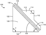
도 1은 제1 프리즘(110), 제2 프리즘(120), 및 반사 편광기(130)를 포함하는 편광 빔 스플리터(100)의 개략 측면도이다. 제1 프리즘(110)은 제1 면(112), 제2 면(114), 제1 빗면(116), 및 제1 및 제2 면들(112, 114)로부터 연장되는 부분(118)을 포함한다. 제1 빗면은 부분(118)의 주 표면을 포함한다. 제2 프리즘(120)은 제3 면(122), 제4 면(124) 및 제2 빗면(126)을 포함한다. 제2 빗면(126)은 제1 빗면(116)에 인접하게 배치되고 반사 편광기(130)는 제1 빗면(116)과 제2 빗면(126) 사이에 배치된다. 편광 빔 스플리터(100)는, 편광 빔 스플리터(100)를 포함하고 예를 들어 하나 이상의 반사 컴포넌트와 같은 하나 이상의 추가 광학 컴포넌트를 포함할 수 있는 편광 빔 분리 시스템의 일부일 수 있다. 편광 빔 스플리터(100)는, 편광 빔 스플리터(100)를 포함하고 예를 들어 광원 및/또는 이미지 형성 디바이스와 같은 하나 이상의 추가 광학 컴포넌트를 포함할 수 있는 조명기의 일부일 수 있다. 조명기에서 사용될 때, 제1 면(112)은 광원으로부터 광을 수신하도록 배치된 입력 면일 수 있고, 제2 면(114)은 출력 면일 수 있으며, 제4 면(124)은 이미지 형성 디바이스에 인접하게 배치된 이미저 면일 수 있다. 다른 실시예들에서, 조명기에서 사용될 때, 제3 면(122)은 광원으로부터 광을 수신하도록 배치된 입력 면일 수 있고, 제2 면(114)은 출력 면일 수 있으며, 제4 면(124)은 이미지 형성 디바이스에 인접하게 배치된 이미저 면일 수 있다.1 is a schematic side view of a
제2 면(114)은 제1 및 제2 면들(112, 114) 사이에 각도(α)를 가지면서 제1 면(112)에 인접한다. 각도(α)는 예를 들어, 80도 내지 100도일 수 있거나, 90도와 동일하거나 실질적으로 동일할 수 있다. 제4 면(124)은 제3 및 제4 면들(122, 124) 사이에 각도(β)를 가지면서 제3 면(122)에 인접한다. 각도(β)는 예를 들어, 80도 내지 100도일 수 있거나, 90도와 동일하거나 실질적으로 동일할 수 있다. 일부 실시예들에서, 제3 면(122)은 제1 면(112)의 반대편에 있고 제1 면(112)과 실질적으로 평행하다. 일부 실시예들에서, 제4 면(124)은 제2 면(114)의 반대편에 있고 제2 면(114)과 실질적으로 평행하다. 일부 실시예들에서, 제2 프리즘(120)은 실질적으로 직각 삼각형 프리즘이다. 일부 실시예들에서, 제1 및 제2 빗면들(116, 126)은 실질적으로 동일한 표면적을 갖는다.The
반사 편광기와 제4 면(124) 사이의 각도(γ)는 예를 들어, 약 30도 또는 약 40도 내지 약 50도 또는 약 60도의 범위 내에 있을 수 있다. 본 명세서의 다른 곳에서 기술된 바와 같이, 편광 빔 스플리터(100)를 포함하는 조명기는 제4 면(124)과 실질적으로 평행한 세그먼트를 갖는 접힌 광축을 가질 수 있고 제4 면(124)에 실질적으로 수직인 다른 세그먼트를 가질 수 있다. 광축과 반사 편광기 사이의 각도는 각도(γ)와 동일할 수 있거나 90도 마이너스 γ와 동일할 수 있다. 일부 실시예들에서, 반사 편광기와 광축 사이의 각도는 약 40도 내지 약 60도 사이이다.The angle [gamma] between the reflective polarizer and the
일부 실시예들에서, 제1 프리즘(110)은 제1 체적을 갖고, 제2 프리즘(120)은 제2 체적을 가지며, 제1 체적은 제2 체적의 약 절반 이하이다. 일부 실시예들에서, 제1 체적은 제2 체적의 35 퍼센트 미만, 또는 40 퍼센트 미만, 또는 50 퍼센트 미만, 또는 60퍼센트 미만이다.In some embodiments, the
일부 실시예들에서, 제1 면(112)은, 가장 큰 영역(제1 면(112)의 전체 면적)이 제3 면(122)의 가장 큰 영역(제3 면(122)의 전체 면적)의 약 절반보다 작고/작거나 제4 면(124)의 가장 큰 영역(제4 면(124)의 전체 면적)의 약 절반보다 작다. 일부 실시예들에서, 제1 면(112)의 가장 큰 영역은 제3 면(122)의 가장 큰 영역의 60 퍼센트 미만, 또는 50 퍼센트 미만, 또는 40 퍼센트 미만, 또는 35 퍼센트 미만이다. 일부 실시예들에서, 제1 면(112)의 가장 큰 영역은 제4 면(124)의 가장 큰 영역의 60 퍼센트 미만, 또는 50 퍼센트 미만, 또는 40 퍼센트 미만, 또는 35 퍼센트 미만이다. 일부 실시예들에서, 제2 면(114)은, 가장 큰 영역(제2 면(114)의 전체 면적)이 제3 면(122)의 가장 큰 영역(제3 면(122)의 전체 면적)의 약 절반보다 작고/작거나 제4 면(124)의 가장 큰 영역(제4 면(124)의 전체 면적)의 약 절반보다 작다. 일부 실시예들에서, 제2 면(114)의 가장 큰 영역은 제3 면(122)의 가장 큰 영역의 60 퍼센트 미만, 또는 50 퍼센트 미만, 또는 40 퍼센트 미만, 또는 35 퍼센트 미만이다. 일부 실시예들에서, 제2 면(114)의 가장 큰 영역은 제4 면(124)의 가장 큰 영역의 60 퍼센트 미만, 또는 50 퍼센트 미만, 또는 40 퍼센트 미만, 또는 35 퍼센트 미만이다. 일부 실시예들에서, 제1 면(112)의 가장 큰 영역 및 제2 면(114)의 가장 큰 영역 각각은 제3 면(122)의 가장 큰 영역 및 제4 면(124)의 가장 큰 영역 중 작은 것의 약 절반보다 작다.In some embodiments, the
도 1에서의 프리즘들 및 반사 편광기는 도시의 명확성을 위해 이격되어 도시된다. 그러나, 다양한 컴포넌트들이 예를 들어 광학적으로 투명한 접착제를 통하여 부착되거나 직접 접촉될 수 있음을 이해해야 한다. 일부 실시예들에서, 반사 편광기(130)는 광학적으로 투명한 접착제(들)를 통하여 제1 및 제2 프리즘들(110, 120) 중 하나 또는 둘 모두에 접합된다.The prisms and the reflective polarizer in Figure 1 are shown spaced apart for clarity of illustration. However, it should be understood that the various components may be attached or directly in contact, for example, through optically transparent adhesives. In some embodiments, the
반사 편광기(130)는 예를 들어 중합체 다층 반사 편광기, 와이어 그리드 편광기, 맥네일(MacNeille) 반사 편광기, 또는 콜레스테릭 반사 편광기와 같은 임의의 적합한 유형의 반사 편광기일 수 있다. 적합한 중합체 다층 반사 편광기들은 예를 들어 미국 특허 제5,882,774호(Jonza 등) 및 미국 특허 제6,609,795호(Weber 등)에 기술되어 있으며, 쓰리엠 컴퍼니(3M Company)(미국 미네소타주 세인트 폴 소재)로부터 입수가능한 어드밴스드 편광 필름(Advanced Polarizing Film, APF)을 포함한다.The
제1 및 제2 프리즘들(110, 120)은 예를 들어 유리, 세라믹 또는 광학 플라스틱(예를 들어, 폴리카보네이트, 폴리메틸메타크릴레이트(PMMA)와 같은 아크릴레이트, 환형 올레핀, 또는 다른 중합체)과 같은 임의의 적합한 재료들로 제조될 수 있다. 제1 및 제2 프리즘들은 예를 들어 성형, 기계 가공, 연삭 및/또는 연마와 같은 임의의 적합한 공정에 의해 제조될 수 있다. 선택된 재료는 낮은 복굴절을 가져서, 광이 제1 또는 제2 프리즘들(110, 120)을 통과함에 따라 편광 상태가 현저히 변경되지 않도록 할 수 있다. 일부 실시예들에서, 반사 편광기(130)의 차단 축(block axis)을 따른 편광을 갖는 광의 약 5 퍼센트, 또는 3 퍼센트, 또는 2 퍼센트, 또는 1 퍼센트 이하가 편광 빔 스플리터(100)를 통하여 투과된다. 일부 실시예들에서, 제1 및 제2 프리즘들(110, 120)에 접합된 반사 편광기(130)의 조합된 반사율은 반사 편광기(130)에 대한 통과 축(pass axis)을 따라 편광된 광에 대해 5 퍼센트 미만, 또는 3 퍼센트 미만, 또는 2 퍼센트 미만, 또는 1 퍼센트 미만이다.The first and
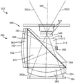
도 2는 편광 빔 스플리터(200) 및 제1 및 제2 반사 컴포넌트들(232, 234)을 포함하는 편광 빔 분리 시스템(204)을 포함하는 조명기(202)의 개략 측면도이다. 조명기(202)는 렌즈(240) 및 광원(250)을 추가로 포함한다. 편광 빔 스플리터(100)에 대응할 수 있는 편광 빔 스플리터(200)는 제1 및 제2 프리즘들(210, 220) 및 반사 편광기(230)를 포함한다. 제1 프리즘(210)은 입력 면(212), 출력 면(214) 및 제1 빗면(216)을 포함한다. 입력 면(212)은 입력 활성 영역(213)을 갖고, 출력 면(214)은 출력 활성 영역(215)을 갖는다. 렌즈(240)는 가장 큰 수용 영역(243)을 갖는다. 제2 프리즘(220)은 이미저 면(224) 및 제2 빗면(226)을 갖는다. 반사 편광기(230)는 제1 및 제2 빗면들(216, 226) 사이에 배치된다. 광원(250)은 제1, 제2, 제3 및 제4 세그먼트들(257a 내지 257d)을 갖는 접힌 광축(257)을 한정하는 중심 광선(256) 및 엔벨로프(252)를 갖는 광 빔을 생성한다. 제1 반사 컴포넌트(232)는 광원(250)의 반대편인 편광 빔 스플리터(200)에 인접하게 배치되고, 제2 반사 컴포넌트(234)는 렌즈(240)의 반대편인 편광 빔 스플리터(200)에 인접하게 배치된다.2 is a schematic side view of a
제2 반사 컴포넌트(234)는 가장 큰 활성 영역(236)을 갖는다. 제2 반사 컴포넌트(234)는 이미지 형성 디바이스일 수 있고, 가장 큰 활성 영역(236)은 이미지 형성 디바이스의 가장 큰 이미지 영역일 수 있다. 광은 엔벨로프(254) 내에서 제2 반사 컴포넌트(234)로부터 (예를 들어, 반사됨으로써) 방출된다. 제1 및 제2 반사 컴포넌트들(232, 234) 중 하나 또는 둘 모두는 경면 반사율이 70 퍼센트 초과, 또는 80 퍼센트 초과, 또는 90 퍼센트 초과일 수 있다. 제1 및/또는 제2 반사 컴포넌트들(232, 234)은 편평하거나 하나 이상의 축에서 만곡되어 있을 수 있다.The second
일부 실시예들에서, 제2 반사 컴포넌트(234)는 그에 입사되는 광을 변조하도록 구성된다. 예를 들어, 제2 반사 컴포넌트(234)는 공간적으로 변조된 편광 상태를 갖는 광을 반사시키는 이미지 형성 디바이스일 수 있다. 제2 반사성 컴포넌트(234)는 픽셀화될 수 있고, 패턴화된 광을 생성할 수 있다. 엔벨로프(254) 내에서 제2 반사 컴포넌트(234)로부터 반사된 광은 수렴 패턴화된 광일 수 있다. 제2 반사 컴포넌트(234)로서 이용될 수 있는 적합한 이미지 형성 디바이스들은 액정 온 실리콘(Liquid Crystal on Silicon, LCoS) 디바이스들을 포함한다. LCoS 디바이스는 편평하거나 하나 이상의 축에서 만곡될 수 있다.In some embodiments, the second
도 2에서의 다양한 컴포넌트들은 도시의 명확성을 위해 이격되어 도시된다. 그러나, 다양한 컴포넌트들이 예를 들어 광학적으로 투명한 접착제를 통하여 부착되거나 직접 접촉될 수 있음을 이해해야 한다. 일부 실시예들에서, 반사 편광기(230)는 광학적으로 투명한 접착제 층들을 사용하여 제1 및 제2 프리즘들(210, 220) 중 하나 또는 둘 모두에 부착된다. 일부 실시예들에서, 렌즈(240)는 광학적으로 투명한 접착제로 출력 면(214)에 부착된다. 일부 실시예들에서, 광원(250)은 입력 면(212)에 바로 인접할 수 있거나 광학적으로 투명한 접착제 층을 통하여 입력 면(212)에 부착될 수 있다. 일부 실시예들에서, 제1 및/또는 제2 반사 컴포넌트들(232, 234)은 광학적으로 투명한 접착제로 제2 프리즘(220)에 부착될 수 있다.The various components in FIG. 2 are shown spaced apart for clarity of illustration. However, it should be understood that the various components may be attached or directly in contact, for example, through optically transparent adhesives. In some embodiments, the
접힌 광축(257)은 광원(250)으로부터 제1 반사 컴포넌트(232)로의 제1 방향(양의 x-방향)으로 연장되는 제1 세그먼트(257a), 제1 방향과 반대인 제2 방향(음의 x-방향)으로 연장되는 제2 세그먼트(257b), 제3 방향(음의 y-방향)으로 연장되는 제3 세그먼트(257c), 및 제3 방향과 반대인 제4 방향(양의 y-방향)으로 연장되는 제4 세그먼트(257d)를 포함한다. 제1 및 제2 세그먼트들(257a, 257b)은 설명을 용이하게 하기 위해 도 2에서 작은 간극을 두고 도시되어 있지만 이들은 중첩되어 있다. 유사하게, 제3 및 제4 세그먼트들(257c, 257d)은 설명을 용이하게 하기 위해 도 2에서 작은 간극을 두고 도시되어 있지만 이들은 중첩되어 있다. 제1 및 제2 방향들은 제3 및 제4 방향들에 실질적으로 직교한다. 제1 반사 컴포넌트(232)는 제1 세그먼트(257a)에 실질적으로 수직이고, 제2 반사 컴포넌트(234)는 제3 세그먼트(257c)에 실질적으로 수직이다.The folded
광원(250)은 엔벨로프(252)를 갖는 광 빔을 생성하고, 이것은 조명기(202)에 의해 사용되는 광원(250)으로부터의 광으로 조명되는 입력 면(212)의 영역으로서 입력 활성 영역(213)을 한정한다. 광원(250)은 실질적으로 엔벨로프(252)의 외측에 광을 생성하지 않을 수 있거나, 또는 이러한 엔벨로프 외측에 생성되는 임의의 광은 렌즈(240)에 들어가지 않고서 조명기로부터 빠져나가는 각도로 있다.The
광원(250)으로부터의 광의 적어도 일부분은 순서대로, 제1 프리즘(210)을 통하여 투과되고, 반사 편광기(230)을 통하여 투과되고, 제2 프리즘(220)을 통하여 투과되고, 제1 반사 컴포넌트(232)로부터 반사되고, 제2 프리즘(220)을 통하여 다시 투과되고, 반사 편광기(230)로부터 반사되고, 제2 프리즘(220)을 통하여 투과되어 제2 반사 컴포넌트(234) 상에 입사되고, 제2 반사 컴포넌트(234)로부터 반사되고, 제2 프리즘(220) 및 반사 편광기(230) 및 제1 프리즘(210)을 통하여 투과되고, 마지막으로 렌즈(240)를 통하여 조명기에서 나온다. 이것은 중심 광선(256)에 대해 도 2에 도시되어 있다. 일부 실시예들에서, 제1 반사 컴포넌트(232)는 편광 회전기를 포함하며, 이는 1/4 파장 지연기일 수 있다. 반사 편광기(230)의 통과 축(pass axis)을 따른 편광을 갖는 광원(250)으로부터의 광은 반사 편광기(230)을 통하여 투과되고 이어서 제1 반사 컴포넌트(232)로부터 다시 반사 편광기(230)을 향해 반사될 것이다. 제1 반사 컴포넌트(232)가 1/4 파장 지연기를 포함하는 실시예들에서, 그러한 광은 다시 반사 편광기(230)를 향해 반사될 때 1/4 파장 지연기를 2번 통과한다. 이러한 광은 이어서 반사 편광기(230)의 통과 축에 실질적으로 직교하는 편광을 가져서, 반사 편광기(230)로부터 제2 반사 컴포넌트(234)를 향해 반사되며, 제2 반사 컴포넌트는 공간적으로 변조된 광을 다시 반사 편광기(230)를 향해 방출할(예를 들어, 반사시킬) 수 있다. 공간적으로 변조된 광은 공간적으로 변조된 편광을 가질 수 있다. 반사 편광기(230)의 통과 축을 따른 편광을 갖는 공간적으로 변조된 광의 부분은 이미징된 광으로서 반사 편광기(230)를 통과하고, 출력 활성 영역(215)을 통하여 제1 프리즘(210)에서 나오고, 렌즈(240)를 통하여 조명기에서 나올 것이다.At least a portion of the light from the
조명기(202)는, 접힌 광 경로 조명기(202)를 통하여 이미지 형성 디바이스(제2 반사 컴포넌트(234)) 상으로 광 빔을 (엔벨로프(252) 내에서) 지향시키고, 이미지 형성 디바이스로부터 수렴 패턴화된 광을 (엔벨로프(254) 내에서) 반사시킴으로써 이미지가 투영되도록 한다. 접힌 광 경로 조명기(202)를 통하여 광 빔을 지향시키는 단계는, 편광 빔 스플리터(200)를 통하여 제1 반사 컴포넌트(232)로 광을 지향시키는 단계, 광의 적어도 일부를 다시 편광 빔 스플리터(200)를 향해 반사시키는 단계, 및 광의 적어도 일부를 편광 빔 스플리터(200)로부터 이미지 형성 디바이스를 향해 반사시키는 단계를 포함한다. 수렴 패턴화된 광의 적어도 일부는 편광 빔 스플리터(200)를 통하여 그리고 렌즈(240)를 통하여 투과된다.The
광원(250)으로부터의 광은, 광이 제1 반사 컴포넌트(232) 및 반사 편광기(230)로부터 반사된 후에 제2 반사 컴포넌트(234)의 최대 영역을 조명한다. 이러한 최대 영역은 가장 큰 활성 영역(236)과 동일할 수 있다. 대안적으로, 가장 큰 활성 영역(236)은 반사성인 제2 반사성 컴포넌트(234)의 가장 큰 영역일 수 있다. 예를 들어, 제2 반사 컴포넌트(234)는 가장 큰 이미지 면적을 갖는 이미지 형성 디바이스일 수 있다. 가장 큰 이미지 영역 외측의 이미지 형성 디바이스 상에 입사되는 임의의 광은 렌즈(240)를 향해 반사되지 않을 수 있다. 이 경우, 가장 큰 활성 영역(236)은 이미지 형성 디바이스의 가장 큰 이미지 영역일 것이다. 가장 큰 활성 영역(236)은 출력 면(214) 상의 출력 활성 영역(215) 및 렌즈(240)의 가장 큰 수용 영역(243)을 한정하는데, 이는 광이 엔벨로프(254) 내에서 가장 큰 활성 영역(236)으로부터 렌즈(240)를 향해 반사되며, 이는 실질적으로 출력 활성 영역(215)에서만 출력 면(214)을 조명하고 실질적으로 가장 큰 수용 영역(243)에서만 렌즈(240)를 조명하기 때문이다. 조명기(202)는, 제2 반사 컴포넌트(234)로부터 반사되고 렌즈(240)를 통과하는 엔벨로프(254) 내의 광이 제2 반사 컴포넌트(234)와 렌즈(240) 사이에서 수렴하도록 구성된다. 이 결과, 가장 큰 활성 영역(236)은 출력 활성 영역(215)보다 작고, 출력 활성 영역(215)은 가장 큰 활성 영역(236)보다 작게 된다.Light from the
일부 실시예들에서, 입력 활성 영역(213) 및/또는 출력 활성 영역(215)은, 가장 큰 이미지 영역일 수 있는 가장 큰 활성 영역(236)의 약 60 퍼센트 미만, 또는 약 50 퍼센트 미만(즉, 약 절반보다 작음), 또는 약 40 퍼센트 미만, 또는 약 35 퍼센트 미만이다. 일부 실시예들에서, 입력 면(212)의 가장 큰 표면적(입력 면(212)의 전체 면적)은 가장 큰 이미지 영역의 약 절반보다 작다. 일부 실시예들에서, 출력 면(214)의 가장 큰 표면적(출력 면(214)의 전체 면적)은 가장 큰 이미지 영역의 약 절반보다 작다.In some embodiments, the input
광원(250), 또는 본 명세서의 광원들 중 임의의 광원은 하나 이상의 실질적으로 단색의 발광 요소를 포함할 수 있다. 예를 들어, 광원(250)은 적색, 녹색 및 청색 발광 다이오드(LED)들을 포함할 수 있다. 청록색(cyan) 및 황색과 같은 다른 색들도 포함될 수 있다. 대안적으로, 또는 추가적으로, 광역 스펙트럼(예를 들어, 백색 또는 실질적으로 백색) 광원들이 이용될 수 있다. 일부 실시예들에서, 광원(250)은 청색 방출체 및 인광체를 포함한다. 일부 실시예들에서, 광원(250)은 별개의 광원들로부터의 광을 조합하는 데 이용될 수 있는 적분기를 포함한다(예를 들어, 적분기는 적색, 녹색 및 청색 LED들로부터의 광을 조합할 수 있다). 광원(250)은 편광 요소를 포함하여서, 실질적으로 단일 편광 상태를 갖는 광이 반사 편광기(230)을 향해 제1 프리즘(210) 내로 지향되도록 할 수 있다. 일부 실시예들에서, 광원(250)은 LED, 유기 발광 다이오드(OLED), 레이저, 레이저 다이오드, 백열 조명 요소, 및 아크 램프 중 하나 이상일 수 있거나 이를 포함할 수 있다. 광원(250)은 또한 LED(들)와 같은 발광 요소(들)에 더하여, 집광 렌즈(condenser lens)와 같은 렌즈를 포함할 수 있다.
일부 실시예들에서, 제1 또는 제2 프리즘들은 원하는 광학 굴절력(optical power)을 제공하기 위해 하나 이상의 만곡된 면을 가질 수 있다. 도 3은 편광 빔 스플리터(300) 및 제1 및 제2 반사 컴포넌트들(332, 334)을 포함하는 편광 빔 분리 시스템(304)을 포함하는 조명기(302)의 측면도이다. 조명기(302)는 투영 렌즈(344)의 요소일 수 있는 렌즈(340), 및 광원(350)을 추가로 포함한다. 편광 빔 스플리터(300)는 제1 및 제2 프리즘들(310, 320) 및 반사 편광기(330)를 포함한다. 제1 프리즘(310)은 입력 면(312) 및 출력 면(314)을 포함한다. 제2 프리즘(320)은 이미저 면(324) 및 제2 면(322)을 갖는다. 반사 편광기(330)는 제1 및 제2 프리즘들(310, 320)의 제1 및 제2 빗면들 사이에 배치된다.In some embodiments, the first or second prisms may have more than one curved surface to provide the desired optical power. 3 is a side view of the
제2 프리즘(320)은 예를 들어 하나 이상의 광학적으로 투명한 접착제를 통하여 제2 프리즘(320)의 몸체(364)에 부착될 수 있는 하나 이상의 컴포넌트(360) 및 하나 이상의 컴포넌트(362)를 포함한다. 일부 실시예들에서, 컴포넌트들(360, 362)은 몸체(364)로부터 (예를 들어, 공기 간극을 두고) 분리될 수 있다. 일부 실시예들에서, 몸체(364)는 직각 삼각형 프리즘일 수 있다. 일부 실시예들에서, 컴포넌트들(360, 362) 중 하나 또는 둘 모두는 예를 들어 사출 성형에 의해 또는 임의의 다른 적합한 성형 공정에 의해 몸체(364)와 일체로 형성될 수 있다. 일부 실시예들에서, 입력 면(312) 및/또는 출력 면(314)은 제1 프리즘(310)의 몸체에 부착된 만곡된 표면(들)을 갖는 하나 이상의 컴포넌트를 유사하게 포함할 수 있거나, 또는 제1 프리즘(310)과 일체로 형성된 만곡된 표면을 포함할 수 있다.The
도시된 실시예들에서, 제1 반사 컴포넌트(332)는 제2 프리즘(320)의 제2 면(322)에 적용된 반사 코팅이고, 1/4 파장 지연기(365)가 본체(364)와 컴포넌트들(362) 사이에 배치된다. 다른 실시예들에서, 컴포넌트(362)는 몸체(364)와 일체로 형성될 수 있고, 1/4 파장 지연기가 제2 면(322)에 적용될 수 있으며, 이어서 반사 코팅이 1/4 파장 지연기에 적용될 수 있다.In the illustrated embodiments, the first
광원(350)은 중심 광선(356) 및 외측 엔벨로프 광선들(352a, 352b)을 생성한다. 광선(352b)(및 광선(352a) 및 중심 광선(356)에 대해서도 유사함)은 반사 편광기(330)의 통과 축을 따른 편광을 가지면서 광원(350)에 의해 방출된다. 광선(352b)은 순서대로, 제1 프리즘(310)을 통과하고, 반사 편광기(330)를 통과하고, 제2 프리즘(320)의 몸체(364)를 통과하고, 1/4 파장 지연기(365)를 통과하고, 컴포넌트들(362)을 통과하고, 제1 반사 컴포넌트(332)에 의해 반사되고, 컴포넌트(362)들을 다시 통과하고, 이어서 다시 1/4 파장 지연기(365)를 그리고 반사 편광기(330)를 향해 다시 본체(364)를 통과한다. 광선(352b)은 1/4 파장 지연기를 2번 통과했으므로, 그것은 반사 편광기(330)의 통과 축에 실질적으로 직교하는 편광을 갖는다. 따라서 광선(352b)은 반사 편광기(330)로부터 반사되고, 몸체(364) 및 컴포넌트들(360)을 통과하고 이어서 제2 반사 컴포넌트(334)로부터 다시 컴포넌트들(360) 및 몸체(364)를 통하여 반사 편광기(330)를 향해 반사된다. 제2 반사 컴포넌트(334)는 제2 반사 컴포넌트(334)로부터 반사된 광의 편광을 공간적으로 변조하는 이미지 형성 디바이스일 수 있다. 이러한 경우들에서, 제2 반사 컴포넌트(334)로부터 반사된 광의 일부분은 반사 편광기(330)의 통과 축을 따른 편광을 가질 수 있다. 이것은 제2 반사 컴포넌트(334)로부터 반사된 후에 반사 편광기(330)를 통과하는 광선(352b)에 해당한다. 이어서 광선(352b)은 제1 프리즘(310)을 통과하고 출력 면(314)을 통하여 나온다. 광선(352b)은 이어서 투영 렌즈(344)를 통과하고 이어서 조명기(302)에서 나온다.The
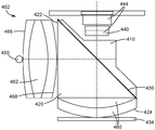
일부 경우들에서, 광원을 보다 작은 프리즘이 아닌, 보다 큰 프리즘에 인접하게 두는 것이 유용할 수 있다. 예시적인 실시예가 도 4에 도시되며, 이는 제1 프리즘(410), 제2 프리즘(420), 반사 편광기(430), 광원(450), 투영 렌즈(444)의 요소인 렌즈(440), 및 제2 프리즘(420)의 면(422)과 광원(450) 사이에 배치된 렌즈(462)를 포함하는 조명기(402)의 측면도이다. 제2 프리즘(420)은 또한 면(424)을 갖고, 제2 프리즘(420)의 몸체와 일체로 형성될 수 있거나 또는 예를 들어 광학적으로 투명한 접착제로 제2 프리즘(420)의 몸체에 부착될 수 있는 컴포넌트들(460)을 포함한다. 렌즈(462)는 각각 제1 및 제2 표면(466, 468)을 갖는다. 광원(450)은 본 명세서의 다른 곳에서 기술된 광원들 중 임의의 것에 대응할 수 있다.In some cases, it may be useful to place the light source adjacent a larger prism, rather than a smaller prism. An exemplary embodiment is shown in Figure 4, which includes a
일부 실시예들에서, 도 4b에 도시된 바와 같이, 제1 표면(466)은 제1 표면(466) 상에 배치된 1/4 파장 지연기(465), 및 1/4 파장 지연기(465) 상에 배치된 반사기(432)(예를 들어, 반사 코팅)를 포함한다. 일부 실시예들에서, 1/4 파장 지연기는 제1 표면(466)에 인접하게(가능하게는, 바로 인접해야 하는 것은 아님) 배치될 수 있고, 반사기가 제1 표면(466)의 반대편인 1/4 파장 지연기에 인접하게(가능하게는, 바로 인접해야 하는 것은 아님) 배치될 수 있다. 반사기는, 광원(450)으로부터 방출된 광이 렌즈(462) 내로 통과하도록, 광원(450)의 방출 면 위의 개구(433)를 포함한다. 개구는 선택적으로 1/4 파장 지연기(465) 내로 연장될 수 있다. 반사 편광기(439)는 제2 표면(468)에 부착될 수 있다. 대안적인 실시예들에서, 반사 편광기(439)는 제2 표면(468)에 인접할 수 있지만 바로 인접해야 하는 것은 아니다.4B, the
반사기(432), 1/4 파장 지연기(465) 및 반사 편광기(439)의 배열은 광원(450)에 편광 변환기를 제공한다. 반사 편광기(439)에 대한 통과 방향을 따른 편광을 갖는 반사 편광기(439) 상에 입사되는 광은 제2 프리즘(420) 내를 향하여 렌즈(462)에서 나온다. 직교 편광을 갖는 광은 반사 편광기(439)로부터 반사되고, 렌즈(462) 및 1/4 파장 지연기(465)를 통과하고, 이어서 반사기(432)로부터 반사되고 반사 편광기(439)를 향해 다시 1/4 파장 지연기(465)를 통과한다. 광은 1/4 파장 지연기(465)를 2번 통과했으므로, 이제 그것은 반사 편광기(439)의 통과 축을 따라 편광되어서, 그것은 제2 프리즘(420) 내를 향하여 반사 편광기(439)를 통과한다.The arrangement of
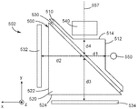
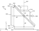
도 5a 및 도 5b는 제1 및 제2 프리즘들(510, 520), 제1 및 제2 프리즘들(510, 520)의 빗면들 사이에 배치된 반사 편광기(530), 제1 및 제2 반사 컴포넌트들(532, 534), 투영 렌즈의 요소일 수 있는 렌즈(540), 및 광원(550)을 포함하는 조명기(502)의 측면도이다. 제1 프리즘(510)은 입력 표면(512) 및 출력 표면(514)을 포함한다. 제2 프리즘(320)은 제1 표면(522) 및 제2 표면(524)을 갖는다. 광원(550)에 의해 방출된 중심 광선은, 중심 광선(256)이 접힌 광축(257)을 한정하는 것과 유사한 방식으로, 접힌 광축(557)을 한정한다. 접힌 광축(557)은 입력 표면(512)과 반사 편광기(530) 사이의 길이(d1), 제1 반사 컴포넌트(532)와 반사 편광기(530) 사이의 길이(d2), 제2 반사 컴포넌트(534)와 반사 편광기(530) 사이의 길이(d3), 및 출력 표면(514)과 반사 편광기(530) 사이의 길이(d4)를 갖는다. 일부 실시예들에서, d1 및 d4 중 하나 또는 둘 모두는 d2 및 d3 중 작은 것보다 작거나, 또는 d2 및 d3 중 작은 것의 0.9배보다 작거나, 또는 d2 및 d3 중 작은 것의 0.85배보다 작다. 일부 실시예들에서, 반사 편광기(530)는 d5의 가장 큰 측방향 치수(본 명세서의 다른 곳에서 추가로 설명됨)를 갖고 d1 및 d4 중 하나 또는 둘 모두는 d5/4보다 작거나, 또는 d5의 0.2배보다 작거나 d5의 0.15배보다 작다.5A and 5B illustrate first and
조명기(502)의 기하학적 구조를 기술하는 데 유용할 수 있는 다른 길이들이 도 5b에 도시되어 있다. 접힌 광축(557)은 광원(550)과 반사 편광기(530) 사이의 길이(d1'), 제2 표면(524)과 반사 편광기(530) 사이의 길이(d2'), 제1 표면(522)과 반사 편광기(530) 사이의 길이(d3'), 및 렌즈(540)와 반사 편광기(530) 사이의 길이(d4')를 갖는다. 일부 실시예들에서, d1' 및 d4' 중 하나 또는 둘 모두는 d2 및 d3 중 작은 것보다 작거나, 또는 d2 및 d3 중 작은 것의 0.9배보다 작거나, 또는 d2 및 d3 중 작은 것의 0.85배보다 작다. 일부 실시예들에서, d1' 및 d4' 중 하나 또는 둘 모두는 d2' 및 d3' 중 작은 것보다 작거나, 또는 d2' 및 d3' 중 작은 것의 0.9배보다 작거나, 또는 d2' 및 d3' 중 작은 것의 0.85배보다 작다. 일부 실시예들에서, 반사 편광기(530)는 d5의 가장 큰 측방향 치수를 갖고, d1' 및 d4' 중 하나 또는 둘 모두는 d5/4보다 작거나, 또는 d5의 0.2배보다 작거나 d5의 0.15배보다 작다.Other lengths that may be useful in describing the geometry of the
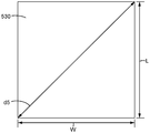
도 5c에 도시된 바와 같이, 반사 편광기(530)은 가장 큰 측방향 치수(d5)를 가질 수 있다. 반사 편광기가 치수들(L, W)을 갖는 변들을 갖는 직사각형 형상인 경우들에서, 반사 편광기(530)의 가장 큰 측방향 치수(d5)는 d5 = (L2+W2)½에 의해 주어진다. 가장 큰 측방향 치수(d5)는 d1의 4배 또는 5배보다 클 수 있고/있거나 d4의 4배 또는 5배보다 클 수 있다. 가장 큰 측방향 치수(d5)는 d1'의 4배 또는 5배보다 클 수 있고/있거나 d4'의 4배 또는 5배보다 클 수 있다. 일부 실시예들에서, 제2 프리즘은 직각 삼각형 프리즘이고, L 및 W는 실질적으로 동일하다. 그러면 길이들(d2', d3')은 대략 L(또는 W)을 2√2로 나눈 것일 수 있고, d5는 대략 d2'의 4배와 동일하거나 대략 d3'의 4배와 동일할 수 있다.As shown in FIG. 5C, the
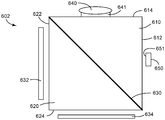
일부 실시예들에서, 접힌 광학계 디자인은 제1 프리즘이 제2 프리즘보다 실질적으로 작은 체적을 갖는 것을 허용한다. 다른 실시예들에서, 제1 및 제2 프리즘들은 실질적으로 동일한 체적을 가질 수 있고, 접힌 광학계 디자인은 작은 수용 영역을 갖는 렌즈와 함께 그리고/또는 작은 방출 영역을 갖는 광원과 함께 사용될 수 있다. 이것은 도 6에 도시되어 있으며, 이것은 제1 및 제2 프리즘(610, 620), 제1 및 제2 프리즘(610, 620) 사이에 배치된 반사 편광기(630), 제1 및 제2 반사 컴포넌트들(632, 634), 및 방출 영역(651)을 갖는 광원(650)을 포함하는 조명기(602)의 측면도이다. 제1 프리즘(610)은 제1 및 제2 표면들(612, 614)을 포함하고, 제2 프리즘(620)은 제1 및 제2 표면들(622, 624)을 포함한다. 조명기(602)는 선택적으로 광학적으로 투명한 접착제 층(641)으로 제1 프리즘(610)에 접합될 수 있는 렌즈(640)를 추가로 포함한다. 제1 반사 컴포넌트(632)는 본 명세서의 다른 곳에서 기술된 바와 같이 1/4 파장 지연기를 포함할 수 있고, 제2 반사 컴포넌트(634)는 본 명세서의 다른 곳에서 기술된 바와 같이 이미지 형성 디바이스일 수 있고 렌즈(640)를 향해 수렴 패턴화된 광을 방출할 수 있다. 광원(650)의 방출 영역(651) 및/또는 렌즈(640)의 수용 영역은 제2 반사 컴포넌트(634)의 가장 큰 활성 영역의 또는 가장 큰 이미지 영역의 60 퍼센트 미만, 또는 50 퍼센트 미만, 또는 40 퍼센트 미만, 또는 35 퍼센트 미만일 수 있다.In some embodiments, the folded optical system design allows the first prism to have a substantially smaller volume than the second prism. In other embodiments, the first and second prisms may have substantially the same volume, and the folded optical system design may be used with a lens having a small receiving area and / or with a light source having a small emitting area. This is illustrated in FIG. 6, which includes first and
도 7은 광원(750), 광원(750)과 광학적으로 연결되는 반사 편광기(730), 및 반사 편광기와 광학적으로 연결되는 렌즈(740)를 포함하는 조명기(702)의 측면도이다. 반사 편광기(730)는, 반사 편광기(730)를 전체적으로 포함하고 광원(750)에 의해 방출된 중심 광선(756)에 수직인 표면(표면들(772, 774))을 갖는 가장 작은 가상 직육면체(770)를 한정한다. 광원(750)의 적어도 일부분 또는 렌즈(740)의 적어도 일부분은 가상 직육면체(770) 내부에 배치된다. 일부 실시예들에서, 광원(750)의 적어도 일부분 및 렌즈(740)의 적어도 일부분은 가상 직육면체(770) 내부에 배치된다. 일부 실시예들에서, 광원(750)의 전부 또는 실질적으로 전부 또는 렌즈(740)의 전부 또는 실질적으로 전부는 가상 직육면체(770) 내부에 배치된다. 일부 실시예들에서, 광원(750)의 전부 및 실질적으로 전부 및 렌즈(740)의 전부 또는 실질적으로 전부는 가상 직육면체(770) 내부에 배치된다.7 is a side view of an
일부 실시예들에서, 렌즈(740)는 투영 렌즈의 요소이다. 일부 실시예들에서, 조명기(702)는 또한 가상 직육면체(770)의 표면(표면들(772, 774))에 실질적으로 수직인 이미지 형성 디바이스(734)를 포함한다. 일부 실시예들에서, 조명기(702)는 본 명세서에 기술된 실시예들 중 임의의 실시예의 제1 및 제2 프리즘들에 대응하는 제1 및/또는 제2 프리즘들을 포함하고/하거나, 예를 들어 도 2 내지 도 5b 중 임의의 도면에 도시된 바와 같은 표면(772)에 근접한 반사 컴포넌트를 포함한다.In some embodiments,
본 명세서의 조명기들은, 예를 들어, 소형 프로젝션이 바람직할 때 유용하다. 본 명세서의 일부 양태들에서, 머리 장착형 디스플레이와 같은 머리 장착형 시스템이 제공된다. 머리 장착형 시스템들은 예를 들어 PCT 공개 WO 2015/034801호(Ouderkirk) 및 미국 가출원 제61/977171호(Ouderkirk 등)에 기술되어 있으며, 이들 각각은 본 명세서와 모순되지 않는 범위에서 본 명세서에 참조로서 포함된다.The fixtures herein are useful, for example, when small projections are desired. In some aspects of the present disclosure, a head mounted system such as a head mounted display is provided. Head-mounted systems are described, for example, in PCT Publications WO 2015/034801 (Ouderkirk) and U.S. Provisional Patent Application 61/977171 (Ouderkirk et al.), Each of which is incorporated herein by reference in its entirety .
도 8은 제1 및 제2 렌즈들(882, 884)을 포함하는 프레임(880)에 장착된 유닛(809)을 포함하는 머리 장착형 시스템(801)의 개략도이다. 유닛(809)은 제1 렌즈(882)에 광을 제공하고/하거나 그로부터 광을 수신하도록 배치된다. 일부 실시예들에서, 제2 유닛이 제1 렌즈(882)에 광을 제공하고/하거나 그로부터 광을 수신하도록 프레임(880)에 장착된다. 유닛(809)은 본 명세서의 조명기들, 편광 빔 스플리터들, 또는 편광 빔 분리 시스템들 중 임의의 것이거나 그를 포함할 수 있다.8 is a schematic diagram of a head mounted
머리 장착형 시스템(801)은 유닛(809)에 포함될 수 있는 눈 모니터링 시스템을 포함할 수 있다. 시스템은 눈의 전방에 위치된 제1 렌즈(882)를 통하여 이미징 센서 및 프로세서로 동공의 직경 및 위치를 모니터링할 수 있다. 제1 렌즈(882)는 그에 인접하거나 그에 내장된, 부분적으로 투명한 반사기를 포함할 수 있으며, 여기서 반사기는 센서 상에 동공의 이미지를 생성한다. 시스템은 주변 광 조건들을 고려한 동공 응답에 기초하여 시스템의 사용자의 피로(fatigue) 및 인지적 처리 부하를 정량화할 수 있고, 이력 데이터에 기초하여 사용자에게 개인맞춤화될 수 있다. 정량화된 정보는 인력 관리 프로그램 또는 스마트폰 애플리케이션과 같은 소프트웨어 애플리케이션을 통하여 보고되고 시각화될 수 있다.The head mounted
눈 모니터링 시스템이 검출할 수 있는 눈의 이들 속성은 눈의 관찰 방향, 동공의 직경 및 직경의 변화, 눈꺼풀의 깜박임, 눈 추적 물체 및 단속성 움직임(saccade movement) 중 하나 이상을 포함할 수 있다. 눈 추적 파라미터들은 눈 회전의 속도, 및 물체의 움직임과 눈의 움직임 사이의 지연 또는 위상을 포함할 수 있다. 단속성 움직임은 움직임의 지속기간, 속도 및 패턴을 포함할 수 있다.These attributes of the eye, which the eye monitoring system can detect, can include one or more of an observation direction of the eye, a change in diameter and diameter of the pupil, blinking of the eyelid, eye tracking object, and saccade movement. The eye tracking parameters may include the speed of the eye rotation and the delay or phase between the motion of the object and the motion of the eye. However, attribute movements can include the duration, velocity and pattern of movement.
일부 실시예들에서, 머리 장착형 시스템(801)은, 유닛(809)에 포함될 수 있고 눈의 이미지를 캡처할 수 있는 카메라(예를 들어, 적-녹-청(RGB) 카메라 또는 적외선(IR) 카메라)를 포함한다. 눈 이미지의 평균 IR 휘도는 주변 광 레벨들을 나타내므로, 주변 광 조건들을 결정하는 데 IR 카메라가 사용될 수 있다. 일부 실시예들에서, 머리 장착형 시스템(801)은 유닛(809)에 포함될 수 있는 임베디드 시스템 상에서 실행되는 컴퓨터 시각 알고리즘을 구현하도록 구성된다.In some embodiments, the head mounted
일부 실시예들에서, 머리 장착형 시스템은 동공 크기의 변화들을 검출하고 그 정보를 이용하여 사용자 피로 및 인지적 처리 부하를 정량화하도록 구성된 눈 추적 시스템을 포함한다. 일부 실시예들에서, 머리 장착형 시스템(801)은 (예를 들어, 임베디드 프로세서 상에서 실행되는 알고리즘을 사용하여) 다음 단계들 중 하나 이상 또는 전부를 구현하도록 구성된다:In some embodiments, the head-mounted system includes an eye tracking system configured to detect changes in pupil size and use the information to quantify user fatigue and cognitive processing load. In some embodiments, the head-mounted
단계 1: 눈의 그레이스케일 이미지를 캡처.Step 1: Capture a grayscale image of the eye.
단계 2: (예를 들어, 가우시안 필터를 사용하여) 노이즈를 필터링.Step 2: Filter the noise (for example, using a Gaussian filter).
단계 3: 눈의 이미지에서의 각각의 픽셀에 대한 구배(gradient) 크기 및 방향을 계산.Step 3: Calculate the gradient magnitude and direction for each pixel in the image of the eye.
단계 4: 더 높은 구배 크기들을 갖는 픽셀들을 식별(이들은 물체의 에지일 가능성이 있음).Step 4: Identify pixels with higher gradient magnitudes (these may be the edges of the object).
단계 5: 예를 들어, 사람의 시각적 지각의 인지의 헬름홀츠 원리(Helmholtz Principle)에 따라 이전 단계에서 식별된 픽셀들을 연결함으로써 에지들을 식별.Step 5: Identify the edges by concatenating the pixels identified in the previous step, for example according to the Helmholtz Principle of perception of a person's visual perception.
단계 6: 에지 선분들을 다항식에 의해 정의되는 타원 또는 다른 형상의 수학식과 비교. 가장 작은 타원형 형상은 동공으로 식별될 수 있다. 홍채의 면적이 또한 결정될 수 있고, 정확도를 향상시키기 위해 사용될 수 있다. 이미지 내에 있을 수 있는 다른 타원 형상들, 예컨대 반짝임(glint)은 제거될 수 있다.Step 6: Compare the edge lines with an ellipse or other form of the equation defined by the polynomial. The smallest elliptical shape can be identified as a pupil. The area of the iris can also be determined and used to improve accuracy. Other elliptical shapes that may be in the image, such as glint, may be eliminated.
단계 7: 이전에 행해진 라인 피팅(line fitting) 및 눈과 카메라 사이의 거리에 기초하여 동공 크기(예를 들어, 직경 또는 면적)를 계산.Step 7: Calculate the pupil size (e.g., diameter or area) based on the previously performed line fitting and the distance between the eye and the camera.
단계 8: 주변 광 조건들을 고려하기 위해 조정 인자를 결정하고 이를 계산된 동공 크기에 적용. 주변 광 조건들은 머리 장착형 시스템 내에 포함된 추가 센서를 사용하여, 또는 캡처된 이미지의 휘도 분석을 통하여 결정될 수 있다.Step 8: Determine the adjustment factor to account for ambient light conditions and apply it to the calculated pupil size. Ambient light conditions may be determined using additional sensors included within the head mounted system, or through a luminance analysis of the captured image.
단계 9: 인지적 처리 부하 및 피로도의 이력 비교 및 분석을 위해, 조정된 동공 크기를 데이터베이스(보안 데이터베이스일 수 있음)에 저장. 이러한 데이터베이스는 가능하게는, 사용자의 정신 상태를 추가로 분석하기 위해 센서 융합 알고리즘에 사용될 수 있는 다른 생물학적 데이터(예를 들어, 심박수, 피부 전도율, 뇌파도(EEG) 등)를 보유할 수 있다. 동공 크기는 시간의 함수로서 기록될 수 있고 시계열(time-series)(시간 경과에 따라 만들어진 일련의 데이터 포인트들)로서 저장될 수 있다.Step 9: Cognitive processing. Store the adjusted pupil size in a database (which can be a security database) for historical comparisons and analysis of load and fatigue. Such a database may possibly have other biological data (e.g., heart rate, skin conductivity, EEG, etc.) that may be used in the sensor fusion algorithm to further analyze the mental state of the user. The pupil size can be recorded as a function of time and can be stored as a time-series (a series of data points made over time).
피로 및 인지적 부하 분석의 방법은 이력 데이터를 이용하여, 현재 레벨들이 임계치를 초과하는지 여부를 결정할 수 있다. 이러한 임계치는 사람마다 다를 수 있으며, 일단 전술된 시스템 및 절차에 의해 충분한 이력 데이터가 수집되면, 기계 학습 알고리즘을 사용하여 결정될 수 있다. 피로도 또는 인지적 처리 부하의 임계치가 초과되는 경우, 예를 들어 사용자 또는 중앙 사무소 관리자에게 경보하기 위해 소프트웨어 애플리케이션이 이용될 수 있다. 또한, 이력 데이터(예를 들어, 동공 직경들의 시계열)는 현재 인지 상태들의 신속한 표시를 위해 소프트웨어 애플리케이션에서 (예를 들어, 시간에 따른 동공 크기의 선 그래프로) 시각화될 수 있다. 눈 추적 시스템은 또한 시간 경과에 따라 시스템에 의해 캡처된 이미지에서의 동공의 위치를 저장함으로써 눈의 움직임을 추적할 수 있다. 동공의 이러한 위치를 시계열로 포함하는 것은 눈이 얼마나 빨리 움직이고 있는지에 대한 정보를 제공할 수 있으며, 이는 느리게 움직이는 눈이 빠르게 움직이는 눈보다 더 피로하므로 피로가 측정될 수 있는 다른 방법을 제공한다.The method of fatigue and cognitive load analysis can use the historical data to determine whether current levels exceed the threshold. These thresholds may vary from person to person and once sufficient history data has been collected by the system and procedures described above, it may be determined using a machine learning algorithm. If the threshold of fatigue or cognitive processing load is exceeded, a software application may be used to alert the user or central office administrator, for example. In addition, the historical data (e.g., time series of pupil diameters) may be visualized in a software application (e.g., with a line graph of pupil size over time) for rapid display of current perceived states. The eye tracking system can also track eye movement by storing the pupil's position in the image captured by the system over time. Including this position of the pupil in a time series can provide information on how fast the eye is moving, which provides another way for fatigue to be measured because slow-moving eyes are more fatigued than fast-moving eyes.
하기는 예시적인 실시예들의 목록이다.The following is a list of exemplary embodiments.
실시예 1은 조명기로서,Example 1 is an illuminator,
편광 빔 스플리터 - 편광 빔 스플리터는,Polarizing Beam Splitter - A polarizing beam splitter,
입력 면, 출력 면 및 제1 빗면을 갖는 제1 프리즘; A first prism having an input surface, an output surface, and a first oblique surface;
이미저 면 및 제2 빗면을 갖는 제2 프리즘 - 제2 빗면은 제1 빗면에 인접하게 배치됨 -; 및 A second prism having an imperforate face and a second oblique face, the second oblique face being disposed adjacent to the first oblique face; And
제1 빗면과 제2 빗면 사이에 배치된 반사 편광기를 포함함 -; And a reflective polarizer disposed between the first and second oblique planes;
입력 면에 인접하게 배치되고 입력 면 상의 입력 활성 영역을 한정하는 광원; 및A light source disposed adjacent the input surface and defining an input active area on the input surface; And
광원으로부터 방출된 광을 수신하고 패턴화된 광을 방출하기 위해 이미저 면에 인접하게 배치된 이미지 형성 디바이스 - 이미지 형성 디바이스는 가장 큰 이미지 영역을 가지며, 가장 큰 이미지 영역은 출력 면 상의 출력 활성 영역을 한정함 - 를 포함하며,An image forming device disposed adjacent the imager surface for receiving light emitted from the light source and emitting the patterned light, the image forming device having a largest image area, the largest image area having an output active area And -
입력 활성 영역 및 출력 활성 영역 중 하나 또는 둘 모두는 가장 큰 이미지 영역의 약 절반보다 작은, 조명기이다.One or both of the input active area and the output active area is an illuminator that is smaller than about half of the largest image area.
실시예 2는 실시예 1의 조명기로서, 입력 활성 영역은 가장 큰 이미지 영역의 약 절반보다 작은, 조명기이다.Example 2 is the illuminator of Example 1 wherein the input active area is an illuminator that is less than about half the largest image area.
실시예 3은 실시예 1의 조명기로서, 출력 활성 영역은 가장 큰 이미지 영역의 약 절반보다 작은, 조명기이다.Example 3 is the illuminator of Example 1 wherein the output active area is an illuminator that is smaller than about half of the largest image area.
실시예 4는 실시예 1의 조명기로서, 입력 활성 영역 및 출력 활성 영역 각각은 가장 큰 이미지 영역의 약 절반보다 작은, 조명기이다.Embodiment 4 is the illuminator of
실시예 5는 실시예 1의 조명기로서, 입력 면의 가장 큰 표면적은 가장 큰 이미지 영역의 약 절반보다 작은, 조명기이다.Example 5 is the illuminator of Example 1, wherein the largest surface area of the input surface is less than about half of the largest image area.
실시예 6은 실시예 1의 조명기로서, 출력 면의 가장 큰 표면적은 가장 큰 이미지 영역의 약 절반보다 작은, 조명기이다.Example 6 is the illuminator of Example 1 wherein the largest surface area of the output surface is less than about half of the largest image area.
실시예 7은 실시예 1의 조명기로서, 입력 면의 가장 큰 표면적은 가장 큰 이미지 영역의 약 절반보다 작고, 출력 면의 가장 큰 표면적은 가장 큰 이미지 영역의 약 절반보다 작은, 조명기이다.Example 7 is the illuminator of Example 1 wherein the largest surface area of the input surface is less than about half the largest image area and the largest surface area of the output surface is less than about half of the largest image area.
실시예 8은 실시예 1의 조명기로서, 광원의 반대편인 편광 빔 스플리터에 인접하게 배치된 반사 컴포넌트를 추가로 포함하는, 조명기이다.Example 8 is an illuminator of Example 1, further comprising a reflective component disposed adjacent a polarizing beam splitter that is opposite to the light source.
실시예 9는 실시예 1의 조명기로서, 반사 편광기는 중합체 다층 반사 편광기, 와이어 그리드 편광기, 맥네일 반사 편광기, 또는 콜레스테릭 반사 편광기인, 조명기이다.Example 9 is the illuminator of Example 1 wherein the reflective polarizer is a polymer multilayer reflective polarizer, a wire grid polarizer, a McNeil reflective polarizer, or a cholesteric reflective polarizer.
실시예 10은 실시예 1의 조명기로서, 반사 편광기는 중합체 다층 반사 편광기인, 조명기이다.Example 10 is an illuminator of Example 1, wherein the reflective polarizer is a polymer multilayer reflective polarizer.
실시예 11은 조명기로서,Example 11 is an illuminator,
편광 빔 스플리터,Polarized beam splitter,
편광 빔 스플리터의 제1 표면에 인접하게 배치된 제1 반사 컴포넌트 - 제1 반사 컴포넌트는 가장 큰 활성 영역을 가짐 -,A first reflective component disposed adjacent a first surface of the polarizing beam splitter, the first reflective component having a largest active area,
제1 표면의 반대편인 편광 빔 스플리터의 제2 표면에 인접하게 배치된 렌즈 - 렌즈는 제1 반사 컴포넌트에 의해 방출된 광을 수신함 - 를 포함하며,A lens-lens disposed adjacent a second surface of the polarizing beam splitter that is opposite the first surface receives light emitted by the first reflective component,
가장 큰 활성 영역은 렌즈의 가장 큰 수용 영역을 한정하고, 가장 큰 수용 영역은 가장 큰 활성 영역의 약 절반 이하인, 조명기이다.The largest active area defines the largest receiving area of the lens, and the largest receiving area is an illuminator that is less than about half the largest active area.
실시예 12는 실시예 11의 조명기로서, 렌즈는 투영 렌즈의 광학 요소인, 조명기이다.Example 12 is the illuminator of Example 11, wherein the lens is an optical element of the projection lens.
실시예 13은 실시예 11의 조명기로서, 렌즈는 접착제 층을 통하여 제2 표면에 접합되는, 조명기이다.Example 13 is the illuminator of Example 11 wherein the lens is bonded to the second surface through an adhesive layer.
실시예 14는 실시예 11의 조명기로서, 제1 반사 컴포넌트는 이미지 형성 디바이스이고 가장 큰 활성 영역은 이미지 형성 디바이스의 가장 큰 이미지 영역인, 조명기이다.Embodiment 14 is the illuminator of embodiment 11 wherein the first reflective component is an image forming device and the largest active area is the largest image area of the image forming device.
실시예 15는 실시예 11의 조명기로서, 편광 빔 스플리터의 제3 표면에 인접하게 배치된 광원을 추가로 포함하며, 제3 표면은 제1 및 제2 표면들과 상이한, 조명기이다.Example 15 is the illuminator of Example 11 further comprising a light source disposed adjacent a third surface of the polarization beam splitter, wherein the third surface is an illuminator different from the first and second surfaces.
실시예 16은 실시예 15의 조명기로서, 광원은 제3 표면 상의 입력 활성 영역을 한정하며, 입력 활성 영역은 가장 큰 활성 영역의 약 절반 이하인, 조명기이다.Example 16 is the illuminator of Example 15 wherein the light source defines an input active area on the third surface and the input active area is an illuminator that is less than about half of the largest active area.
실시예 17은 실시예 15의 조명기로서, 제3 표면의 반대편인 편광 빔 스플리터의 제4 표면에 인접하게 배치된 제2 반사 컴포넌트를 추가로 포함하는, 조명기이다.Example 17 is an illuminator of Example 15, further comprising a second reflective component disposed adjacent a fourth surface of the polarizing beam splitter that is opposite to the third surface.
실시예 18은 광원, 광원과 광학적으로 연결되는 반사 편광기, 및 반사 편광기와 광학적으로 연결되는 렌즈를 포함하는 조명기로서, 반사 편광기는 반사 편광기를 전체적으로 포함하는 가장 작은 가상 직육면체를 한정하고 광원에 의해 방출된 중심 광선에 수직인 표면을 가지며, 광원의 적어도 일부분 또는 렌즈의 적어도 일부분은 가상 직육면체 내부에 배치되는, 조명기이다.Example 18 is an illuminator comprising a light source, a reflective polarizer optically coupled to the light source, and a lens optically coupled to the reflective polarizer, wherein the reflective polarizer defines the smallest virtual rectangle including the entire reflective polarizer, Wherein at least a portion of the light source or at least a portion of the lens is disposed within the virtual parallelepiped.
실시예 19는 실시예 18의 조명기로서, 렌즈는 투영 렌즈의 광학 요소인, 조명기이다.Example 19 is the illuminator of Example 18, in which the lens is an optical element of the projection lens.
실시예 20은 실시예 18의 조명기로서, 표면에 실질적으로 수직인 이미지 형성 디바이스를 추가로 포함하는, 조명기이다.Example 20 is the illuminator of Example 18, further comprising an image forming device substantially perpendicular to the surface.
실시예 21은 실시예 18의 조명기로서,Example 21 is the illuminator of Example 18,
제1 및 제2 면들을 갖고 제1 빗면을 갖는 제1 프리즘, 및A first prism having first and second surfaces and having a first oblique surface, and
제3 및 제4 면들 및 제2 빗면을 갖는 제2 프리즘을 추가로 포함하며, 제3 면은 제1 면의 반대편에 있고, 제4 면은 제2 면의 반대편에 있으며, 반사 편광기는 제1 빗면과 제2 빗면 사이에 그리고 이들에 인접하게 배치되는, 조명기이다.Wherein the third surface is on the opposite side of the first side and the fourth side is on the opposite side of the second side and the reflective polarizer comprises a first prism having a third, And is disposed between and adjacent to the oblique and second oblique faces.
실시예 22는 실시예 21의 조명기로서, 광원은 제1 면에 인접하게 배치되고 렌즈는 제2 면에 인접하게 배치되는, 조명기이다.Example 22 is the illuminator of Example 21 wherein the light source is disposed adjacent the first side and the lens is disposed adjacent the second side.
실시예 23은 실시예 21의 조명기로서, 제4 면에 인접하게 배치된 이미지 형성 디바이스를 추가로 포함하는, 조명기이다.Embodiment 23 is the illuminator of Embodiment 21, further comprising an image forming device disposed adjacent to the fourth surface.
실시예 24는 실시예 21의 조명기로서, 제3 면에 인접하게 배치된 반사 컴포넌트를 추가로 포함하는, 조명기이다.Embodiment 24 is the illuminator of embodiment 21, further comprising a reflective component disposed adjacent to the third surface.
실시예 25는 실시예 21의 조명기로서, 제1 및 제2 면들 중 하나 또는 둘 모두는 제4 면의 가장 큰 영역의 약 절반 이하인 가장 큰 영역을 갖는, 조명기이다.Example 25 is an illuminator of Example 21 wherein one or both of the first and second sides have a largest area that is less than about half the largest area of the fourth side.
실시예 26은 편광 빔 스플리터로서,Example 26 is a polarizing beam splitter,
반사 편광기,Reflective polarizer,
제1 프리즘 - 제1 프리즘은 제1 체적을 갖고,The first prism-first prism has a first volume,
제1 면; A first side;
제1 면에 인접한 제2 면 - 제1 및 제2 면들 사이의 각도는 실질적으로 90도와 동일함 -; The second side adjacent to the first side - the angle between the first and second sides being substantially equal to 90 degrees;
각도의 반대편인 제1 빗면을 포함함 -; 및 A first oblique surface opposite the angle; And
제2 체적을 갖는 제2 프리즘 - 제2 프리즘은 제3 및 제4 면들을 갖고 제2 빗면을 갖는 직각 삼각 프리즘이며, 제2 빗면은 제1 빗면에 인접하게 배치되고, 제1 및 제2 빗면들은 실질적으로 동일한 표면적을 가지며, 제3 면은 제1 면의 반대편에 있고 제1 면과 실질적으로 평행하며, 제4 면은 제2 면의 반대편에 있고 제2 면과 실질적으로 평행함 - 을 포함하며,A second prism having a second volume and a second prism is a right triangular prism having third and fourth surfaces and a second oblique surface, the second oblique surface is disposed adjacent to the first oblique surface, The third surface being on the opposite side of the first surface and being substantially parallel to the first surface and the fourth surface being on the opposite side of the second surface and being substantially parallel to the second surface In addition,
반사 편광기는 제1 빗면과 제2 빗면 사이에 배치되고,The reflective polarizer is disposed between the first and second oblique surfaces,
제1 체적은 제2 체적의 약 절반 이하인, 편광 빔 스플리터이다.The first volume is a polarization beam splitter that is less than about half of the second volume.
실시예 27은 실시예 26의 편광 빔 스플리터로서, 제1 면은, 가장 큰 영역이 제3 면의 가장 큰 영역의 약 절반보다 작고 제4 면의 가장 큰 영역의 약 절반보다 작은, 편광 빔 스플리터이다.Embodiment 27 is a polarizing beam splitter of Embodiment 26 wherein the first surface is a polarizing beam splitter having the largest area smaller than about half of the largest area of the third surface and less than about half of the largest area of the fourth surface, to be.
실시예 28은 실시예 26의 편광 빔 스플리터로서, 제2 면은, 가장 큰 영역이 제3 면의 가장 큰 영역의 약 절반보다 작고 제4 면의 가장 큰 영역의 약 절반보다 작은, 편광 빔 스플리터이다.Embodiment 28 is a polarizing beam splitter of Embodiment 26 in which the second surface is a polarizing beam splitter having the largest area smaller than about half of the largest area of the third surface and less than about half of the largest area of the fourth surface, to be.
실시예 29는 실시예 26의 편광 빔 스플리터로서, 제1 면의 가장 큰 영역 및 제2 면의 가장 큰 영역 각각은 제3 면의 가장 큰 영역 및 제4 면의 가장 큰 영역 중 작은 것의 약 절반보다 작은, 편광 빔 스플리터이다.Embodiment 29 is the polarized beam splitter of Embodiment 26, wherein the largest region of the first surface and the largest region of the second surface are the largest region of the third surface and the largest region of the fourth surface, Polarized beam splitter.
실시예 30은 실시예 26의 편광 빔 스플리터로서, 제1 및 제2 측면들로부터 연장되는 일부분을 추가로 포함하며, 제1 빗면은 상기 부분의 주 표면을 포함하는, 편광 빔 스플리터이다.Embodiment 30 is the polarizing beam splitter of Embodiment 26 further comprising a portion extending from the first and second sides, wherein the first oblique plane comprises the major surface of the portion.
실시예 31은 광원으로부터 광을 수신하도록 구성되고 광원에 의해 방출된 중심 광선의 광학 경로에 의해 한정된 접힌 광축을 중심으로 위치되는 편광 빔 분리 시스템으로서, 편광 빔 분리 시스템은,Embodiment 31 is a polarization beam splitting system configured to receive light from a light source and positioned about a folded optical axis defined by an optical path of a central ray emitted by the light source,
광축에 실질적으로 수직인 입력 표면 - 광은 입력 표면을 통과함으로써 편광 빔 분리 시스템에 들어감 -;Input surface substantially perpendicular to the optical axis - light entering the polarization beam splitting system by passing through the input surface;
반사 편광기 - 광축은 입력 표면과 반사 편광기 사이에서 길이(d1)를 가짐 -;Reflective Polarizer - The optical axis has a length (d1) between the input surface and the reflective polarizer;
광축에 실질적으로 수직인 제1 반사 컴포넌트 - 광축은 제1 반사 컴포넌트와 반사 편광기 사이에서 길이(d2)를 가짐 -;A first reflective component substantially perpendicular to the optical axis, the optical axis having a length (d2) between the first reflective component and the reflective polarizer;
광축에 실질적으로 수직인 제2 반사 컴포넌트 - 광축은 제2 반사 컴포넌트와 반사 편광기 사이에서 길이(d3)를 가짐 -; 및A second reflective component substantially perpendicular to the optical axis, the optical axis having a length (d3) between the second reflective component and the reflective polarizer; And
광축에 실질적으로 수직인 출력 면을 포함하며,And an output surface substantially perpendicular to the optical axis,
광은 출력 표면을 통과함으로써 편광 빔 분리 시스템에서 나오고, 광축은 출력 표면과 반사 편광기 사이에서 길이(d4)를 가지며, d1 및 d4 중 하나 또는 둘 모두는 d2 및 d3 중 작은 것보다 작은, 편광 빔 분리 시스템이다.The light exits the polarization beam splitting system by passing through the output surface and the optical axis has a length d4 between the output surface and the reflective polarizer and one or both of d1 and d4 is smaller than the smaller of d2 and d3, Separation system.
실시예 32는 실시예 31의 편광 빔 분리 시스템으로서, d4는 d2 및 d3 중 작은 것보다 작은, 편광 빔 분리 시스템이다.Embodiment 32 is the polarization beam splitting system of Embodiment 31, wherein d4 is a polarization beam splitting system smaller than the smaller of d2 and d3.
실시예 33은 실시예 31의 편광 빔 분리 시스템으로서, d1은 d2 및 d3 중 작은 것보다 작은, 편광 빔 분리 시스템이다.Example 33 is a polarizing beam splitting system of Example 31 wherein d1 is a polarization beam splitting system smaller than the smaller of d2 and d3.
실시예 34는 실시예 31의 편광 빔 분리 시스템으로서, d1 및 d4 둘 모두는 d2 및 d3 중 작은 것보다 작은, 편광 빔 분리 시스템이다.Embodiment 34 is the polarizing beam splitting system of Embodiment 31, wherein d1 and d4 are both smaller than the smaller of d2 and d3, the polarization beam splitting system.
실시예 35는 실시예 31의 편광 빔 분리 시스템으로서, d1 및 d4 중 하나 또는 둘 모두는 d2 및 d3 중 작은 것의 0.9배보다 작은, 편광 빔 분리 시스템이다.Embodiment 35 is the polarization beam splitting system of Embodiment 31, wherein one or both of d1 and d4 is less than 0.9 times smaller than d2 and d3, whichever is smaller.
실시예 36은 실시예 31의 편광 빔 분리 시스템으로서, 반사 편광기는 d5의 가장 큰 측방향 치수를 가지며, d1 및 d4 중 하나 또는 둘 모두는 d5/4보다 작은, 편광 빔 분리 시스템이다.Example 36 is a polarizing beam splitting system of Example 31 wherein the reflective polarizer has the largest lateral dimension of d5, and one or both of d1 and d4 is less than d5 / 4.
실시예 37은 실시예 36의 편광 빔 분리 시스템으로서, d1 및 d4 각각은 d5/4보다 작은, 편광 빔 분리 시스템이다.Example 37 is the polarizing beam splitting system of Example 36, wherein d1 and d4 are each less than d5 / 4.
실시예 38은 실시예 36의 편광 빔 분리 시스템으로서, d1 및 d4 중 하나 또는 둘 모두는 d5의 0.2배보다 작은, 편광 빔 분리 시스템이다.Embodiment 38 is the polarizing beam splitting system of Embodiment 36, wherein one or both of d1 and d4 is less than 0.2 times d5.
실시예 39는 실시예 31의 편광 빔 분리 시스템으로서, 제2 반사 컴포넌트는 그에 입사되는 광을 변조하도록 구성되는, 편광 빔 분리 시스템이다.Embodiment 39. The polarized beam splitting system of embodiment 31, wherein the second reflective component is configured to modulate light incident thereon.
실시예 40은 실시예 31의 편광 빔 분리 시스템으로서, 제2 반사 컴포넌트는 픽셀화되는, 편광 빔 분리 시스템이다.Example 40 is a polarizing beam splitting system of Example 31, wherein the second reflecting component is a polarized beam splitting system.
실시예 41은 실시예 31의 편광 빔 분리 시스템으로서, 반사 편광기와 광축 사이의 각도는 약 40도 내지 60도 사이인, 편광 빔 분리 시스템이다.Example 41 is a polarizing beam splitting system of Example 31 wherein the angle between the reflective polarizer and the optical axis is between about 40 degrees and about 60 degrees.
실시예 42는 실시예 31의 편광 빔 분리 시스템으로서, 제1 반사 컴포넌트는 약 80%보다 큰 경면 반사율을 갖는, 편광 빔 분리 시스템이다.Example 42 is a polarizing beam splitting system of Example 31 wherein the first reflecting component is a polarizing beam splitting system having a mirror reflectance greater than about 80%.
실시예 43은 실시예 31의 편광 빔 분리 시스템으로서, 제2 반사 컴포넌트는 약 80%보다 큰 경면 반사율을 갖는, 편광 빔 분리 시스템이다.Example 43 is a polarizing beam splitting system of Example 31 wherein the second reflecting component is a polarizing beam splitting system having a mirror reflectance greater than about 80%.
실시예 44는 광원으로부터 광을 수신하도록 구성되고 광원에 의해 방출된 중심 광선의 광학 경로에 의해 한정된 접힌 광축을 중심으로 위치되는 편광 빔 분리 시스템으로서, 편광 빔 분리 시스템은,Embodiment 44 is a polarization beam splitting system configured to receive light from a light source and positioned about a folded optical axis defined by an optical path of a central light beam emitted by the light source,
광축에 실질적으로 수직인 입력 표면 - 광은 입력 표면을 통과함으로써 편광 빔 분리 시스템에 들어감 -;Input surface substantially perpendicular to the optical axis - light entering the polarization beam splitting system by passing through the input surface;
가장 큰 측방향 치수(d5)를 갖는 반사 편광기 - 광축은 입력 표면과 반사 편광기 사이에서 길이(d1)를 가짐 -;A reflective polarizer having a largest lateral dimension, d5, the optical axis having a length d1 between the input surface and the reflective polarizer;
광축에 실질적으로 수직인 제1 반사 컴포넌트 - 광축은 제1 반사 컴포넌트와 반사 편광기 사이에서 길이(d2)를 가짐 -;A first reflective component substantially perpendicular to the optical axis, the optical axis having a length (d2) between the first reflective component and the reflective polarizer;
광축에 실질적으로 수직인 제2 반사 컴포넌트 - 광축은 제2 반사 컴포넌트와 반사 편광기 사이에서 길이(d3)를 가짐 -; 및A second reflective component substantially perpendicular to the optical axis, the optical axis having a length (d3) between the second reflective component and the reflective polarizer; And
광축에 실질적으로 수직인 출력 면 - 광은 출력 표면을 통과함으로써 편광 빔 분리 시스템에서 나오고, 광축은 출력 표면과 반사 편광기 사이에서 길이(d4)를 가짐 - 을 포함하며,An output surface substantially perpendicular to the optical axis - light exiting the polarization beam splitting system by passing through the output surface, the optical axis having a length (d4) between the output surface and the reflective polarizer,
d1 및 d4 중 하나 또는 둘 모두는 d5/4보다 작은, 편광 빔 분리 시스템이다.One or both of d1 and d4 is a polarization beam splitting system that is less than d5 / 4.
실시예 45는 실시예 44의 편광 빔 분리 시스템으로서, d1은 d5/4보다 작은, 편광 빔 분리 시스템이다.Example 45 is the polarizing beam splitting system of Example 44, wherein d1 is a polarization beam splitting system smaller than d5 / 4.
실시예 46은 실시예 44의 편광 빔 분리 시스템으로서, d4는 d5/4보다 작은, 편광 빔 분리 시스템이다.Example 46 is a polarizing beam splitting system of Example 44, wherein d4 is a polarization beam splitting system smaller than d5 / 4.
실시예 47은 실시예 44의 편광 빔 분리 시스템으로서, d1 및 d4 각각은 d5/4보다 작은, 편광 빔 분리 시스템이다.Example 47 is the polarizing beam splitting system of Example 44, wherein d1 and d4 are each less than d5 / 4.
실시예 48은 실시예 44의 편광 빔 분리 시스템으로서, d1 및 d4 중 하나 또는 둘 모두는 d5의 0.2배보다 작은, 편광 빔 분리 시스템이다.Embodiment 48 is the polarization beam splitting system of Embodiment 44, wherein one or both of d1 and d4 is less than 0.2 times d5.
실시예 49는 실시예 44의 편광 빔 분리 시스템으로서, d1 및 d4 중 하나 또는 둘 모두는 d2 및 d3 중 작은 것보다 작은, 편광 빔 분리 시스템이다.Embodiment 49. The polarization beam splitting system of embodiment 44, wherein one or both of d1 and d4 is a polarization beam splitting system smaller than the smaller of d2 and d3.
실시예 50은 실시예 49의 편광 빔 분리 시스템으로서, d1은 d2 및 d3 중 작은 것보다 작은, 편광 빔 분리 시스템이다.Example 50 is a polarizing beam splitting system of Example 49, wherein d1 is a polarization beam splitting system smaller than the smaller of d2 and d3.
실시예 51는 실시예 49의 편광 빔 분리 시스템으로서, d4는 d2 및 d3 중 작은 것보다 작은, 편광 빔 분리 시스템이다.Embodiment 51 is the polarization beam splitting system of Embodiment 49, wherein d4 is a polarization beam splitting system smaller than the smaller of d2 and d3.
실시예 52는 실시예 49의 편광 빔 분리 시스템으로서, d1 및 d4 각각은 d2 및 d3 중 작은 것보다 작은, 편광 빔 분리 시스템이다.Embodiment 52. The polarization beam splitting system of embodiment 49, wherein d1 and d4 are each a polarization beam splitting system smaller than the smaller of d2 and d3.
실시예 53은 실시예 52의 편광 빔 분리 시스템으로서, d1 및 d4 각각은 d2 및 d3 중 작은 것의 0.9배보다 작은, 편광 빔 분리 시스템이다.Embodiment 53 is the polarization beam splitting system of Embodiment 52, wherein d1 and d4 are each less than 0.9 times smaller than d2 and d3, respectively.
실시예 54는 실시예 44의 편광 빔 분리 시스템으로서, 제1 반사 컴포넌트는 약 80%보다 큰 경면 반사율을 갖는, 편광 빔 분리 시스템이다.Example 54 is a polarizing beam splitting system of Example 44 wherein the first reflecting component is a polarizing beam splitting system having a mirror reflectance greater than about 80%.
실시예 55는 실시예 44의 편광 빔 분리 시스템으로서, 제2 반사 컴포넌트는 약 80%보다 큰 경면 반사율을 갖는, 편광 빔 분리 시스템이다.Example 55 is a polarizing beam splitting system of Example 44 wherein the second reflecting component is a polarizing beam splitting system having a mirror reflectance greater than about 80%.
실시예 56은 광원, 렌즈, 및 광원으로부터 광을 수신하고 렌즈를 통하여 광을 출력하도록 구성된 편광 빔 분리 시스템을 포함하는 조명기로서, 편광 빔 분리 시스템은 광원에 의해 방출된 중심 광선의 광학 경로에 의해 한정된 접힌 광축을 중심으로 위치되며, 편광 빔 분리 시스템은,Example 56 is an illuminator comprising a light source, a lens, and a polarizing beam splitting system configured to receive light through the lens and to receive light from the light source, wherein the polarizing beam splitting system is configured by an optical path of the central ray emitted by the light source The polarization beam splitting system being positioned about a limited folded optical axis,
반사 편광기 - 광축은 광원과 반사 편광기 사이에서 길이(d1)를 가짐 -;Reflective polarizer - the optical axis has a length (d1) between the light source and the reflective polarizer;
광축에 실질적으로 수직이고, 광원의 반대편인 반사 편광기에 근접하게 배치된 제1 반사 컴포넌트 - 광축은 제1 반사 컴포넌트와 반사 편광기 사이에서 길이(d2)를 가짐 -;A first reflective component-optical axis substantially perpendicular to the optical axis and disposed adjacent to a reflective polarizer opposite the light source, the optical axis having a length (d2) between the first reflective component and the reflective polarizer;
광축에 실질적으로 수직이고, 렌즈의 반대편인 반사 편광기에 근접하게 배치된 제2 반사 컴포넌트 - 광축은 제2 반사 컴포넌트와 반사 편광기 사이에서 길이(d3)를 가짐 - 를 포함하며,A second reflective component-optical axis substantially perpendicular to the optical axis and disposed proximate to a reflective polarizer opposite the lens, the optical axis having a length (d3) between the second reflective component and the reflective polarizer,
광축은 렌즈와 반사 편광기 사이에서 길이(d4)를 갖고, d1 및 d4 중 하나 또는 둘 모두는 d2 및 d3 중 작은 것보다 작은, 조명기이다.The optical axis has a length d4 between the lens and the reflective polarizer, and one or both of d1 and d4 is an illuminator that is smaller than the smaller of d2 and d3.
실시예 57은 실시예 56의 조명기로서, d4는 d2 및 d3 중 작은 것보다 작은, 조명기이다.Example 57 is the illuminator of Example 56, wherein d4 is an illuminator smaller than the smaller of d2 and d3.
실시예 58은 실시예 56의 조명기로서, d1은 d2 및 d3 중 작은 것보다 작은, 조명기이다.Example 58 is the illuminator of Example 56, wherein d1 is an illuminator smaller than the smaller of d2 and d3.
실시예 59는 실시예 56의 조명기로서, d1 및 d4 둘 모두는 d2 및 d3 중 작은 것보다 작은, 조명기이다.Embodiment 59. The illuminator of embodiment 56, wherein d1 and d4 are both smaller than d2 and d3, the illuminator.
실시예 60은 실시예 56의 조명기로서, d1 및 d4 중 하나 또는 둘 모두는 d2 및 d3 중 작은 것의 0.9배보다 작은, 조명기이다.Example 60 is the illuminator of Example 56, wherein one or both of d1 and d4 is an illuminator less than 0.9 times smaller than d2 and d3.
실시예 61은 실시예 56의 조명기로서, 반사 편광기는 d5의 가장 큰 측방향 치수를 가지며, d1 및 d4 중 하나 또는 둘 모두는 d5/4보다 작은, 조명기이다.Example 61 is the illuminator of Example 56 wherein the reflective polarizer has the largest lateral dimension of d5, and one or both of d1 and d4 is less than d5 / 4.
실시예 62는 실시예 61의 조명기로서, d1 및 d4 각각은 d5/4보다 작은, 조명기이다.Example 62 is the illuminator of Example 61, wherein each of d1 and d4 is an illuminator smaller than d5 / 4.
실시예 63은 실시예 61의 조명기로서, d1 및 d4 중 하나 또는 둘 모두는 d5의 0.2배보다 작은, 조명기이다.Example 63 is the illuminator of Example 61, wherein one or both of d1 and d4 is an illuminator less than 0.2 times d5.
실시예 64는 실시예 56의 조명기로서, 제2 반사 컴포넌트는 그에 입사되는 광을 변조하도록 구성되는, 조명기이다.Embodiment 64. The illuminator of embodiment 56 wherein the second reflective component is an illuminator configured to modulate light incident thereon.
실시예 65은 실시예 56의 조명기로서, 제2 반사 컴포넌트는 픽셀화되는, 조명기이다.Example 65 is the illuminator of Example 56, and the second reflective component is a pixellated illuminator.
실시예 66은 실시예 56의 조명기로서, 반사 편광기와 광축 사이의 각도는 약 40도 내지 60도 사이인, 조명기이다.Example 66 is the illuminator of Example 56 wherein the angle between the reflective polarizer and the optical axis is between about 40 degrees and about 60 degrees.
실시예 67은 실시예 56의 조명기로서, 제1 반사 컴포넌트는 약 80%보다 큰 경면 반사율을 갖는, 조명기이다.Example 67 is the illuminator of Example 56 wherein the first reflective component is a fixture having a specular reflectance greater than about 80%.
실시예 68은 실시예 56의 조명기로서, 제2 반사 컴포넌트는 약 80%보다 큰 경면 반사율을 갖는, 조명기이다.Example 68 is an illuminator of Example 56 wherein the second reflective component is a fixture having a specular reflectance greater than about 80%.
실시예 69는 광원, 렌즈, 및 광원으로부터 광을 수신하고 렌즈를 통하여 광을 출력하도록 구성된 편광 빔 분리 시스템을 포함하는 조명기로서, 편광 빔 분리 시스템은 광원에 의해 방출된 중심 광선의 광학 경로에 의해 한정된 접힌 광축을 중심으로 위치되며, 편광 빔 분리 시스템은,Embodiment 69 is an illuminator comprising a light source, a lens, and a polarizing beam splitting system configured to receive light through a lens and to receive light from the light source, wherein the polarizing beam splitting system is configured by an optical path of a central ray emitted by the light source The polarization beam splitting system being positioned about a limited folded optical axis,
가장 큰 측방향 치수(d5)를 갖는 반사 편광기 - 광축은 광원과 반사 편광기 사이에서 길이(d1)를 가짐 -;A reflective polarizer having a largest lateral dimension (d5), the optical axis having a length (d1) between the light source and the reflective polarizer;
광축에 실질적으로 수직이고, 광원의 반대편인 반사 편광기에 근접하게 배치된 제1 반사 컴포넌트 - 광축은 제1 반사 컴포넌트와 반사 편광기 사이에서 길이(d2)를 가짐 -;A first reflective component-optical axis substantially perpendicular to the optical axis and disposed adjacent to a reflective polarizer opposite the light source, the optical axis having a length (d2) between the first reflective component and the reflective polarizer;
광축에 실질적으로 수직이고, 렌즈의 반대편인 반사 편광기에 근접하게 배치된 제2 반사 컴포넌트 - 광축은 제2 반사 컴포넌트와 반사 편광기 사이에서 길이(d3)를 가짐 - 를 포함하며,A second reflective component-optical axis substantially perpendicular to the optical axis and disposed proximate to a reflective polarizer opposite the lens, the optical axis having a length (d3) between the second reflective component and the reflective polarizer,
광축은 렌즈와 반사 편광기 사이에서 길이(d4)를 갖고, d1 및 d4 중 하나 또는 둘 모두는 d5/4보다 작은, 조명기이다.The optical axis is a fixture having a length d4 between the lens and the reflective polarizer, and one or both of d1 and d4 is less than d5 / 4.
실시예 70은 실시예 69의 조명기로서, d1은 d5/4보다 작은, 조명기이다.Example 70 is the illuminator of Example 69, wherein d1 is an illuminator less than d5 / 4.
실시예 71은 실시예 69의 조명기로서, d4는 d5/4보다 작은, 조명기이다.Example 71 is the illuminator of Example 69, wherein d4 is an illuminator less than d5 / 4.
실시예 72는 실시예 69의 조명기로서, d1 및 d4 각각은 d5/4보다 작은, 조명기이다.Example 72 is the illuminator of Example 69 wherein each of d1 and d4 is an illuminator less than d5 / 4.
실시예 73은 실시예 69의 조명기로서, d1 및 d4 중 하나 또는 둘 모두는 d5의 0.2배보다 작은, 조명기이다.Embodiment 73 is the illuminator of embodiment 69 wherein one or both of d1 and d4 is an illuminator that is less than 0.2 times d5.
실시예 74는 실시예 69의 조명기로서, d1 및 d4 중 하나 또는 둘 모두는 d2 및 d3 중 작은 것보다 작은, 조명기이다.Embodiment 74. The illuminator of embodiment 69 wherein one or both of d1 and d4 is an illuminator that is smaller than the smaller of d2 and d3.
실시예 75은 실시예 74의 조명기로서, d1은 d2 및 d3 중 작은 것보다 작은, 조명기이다.Embodiment 75 is the illuminator of embodiment 74, wherein d1 is a smaller illuminator than d2 and d3, whichever is smaller.
실시예 76은 실시예 74의 조명기로서, d4는 d2 및 d3 중 작은 것보다 작은, 조명기이다.Embodiment 76 is the illuminator of embodiment 74, wherein d4 is an illuminator smaller than the smaller of d2 and d3.
실시예 77은 실시예 74의 조명기로서, d1 및 d4 각각은 d2 및 d3 중 작은 것보다 작은, 조명기이다.Embodiment 77 is the illuminator of embodiment 74, wherein d1 and d4 are each an illuminator smaller than the smaller of d2 and d3.
실시예 78은 실시예 74의 조명기로서, d1 및 d4 각각은 d2 및 d3 중 작은 것의 0.9배보다 작은, 조명기이다.Embodiment 78. The illuminator of embodiment 74 wherein d1 and d4 are each an illuminator less than 0.9 times smaller than d2 and d3.
실시예 79는 실시예 69의 조명기로서, 제1 반사 컴포넌트는 약 80%보다 큰 경면 반사율을 갖는, 조명기이다.Embodiment 79. The illuminator of embodiment 69 wherein the first reflective component is an illuminator having a mirror reflectance greater than about 80%.
실시예 80은 실시예 69의 조명기로서, 제2 반사 컴포넌트는 약 80%보다 큰 경면 반사율을 갖는, 조명기이다.Embodiment 80 is the illuminator of Embodiment 69, wherein the second reflective component is an illuminator having a mirror reflectance greater than about 80%.
실시예 81은 광원, 반사 편광기, 제1 반사 컴포넌트, 제2 반사 컴포넌트 및 렌즈를 포함하는 조명기로서, 조명기는, 광원에 의해 방출된 중심 광선이 순서대로, 반사 편광기를 통과하고, 제1 반사 컴포넌트로부터 다시 반사 편광기를 향해 반사되고, 반사 편광기로부터 제2 반사 컴포넌트를 향해 반사되고, 제2 반사 컴포넌트로부터 다시 반사 편광기를 향해 반사되고, 반사 편광기를 통과하고 이어서 렌즈를 통하여 조명기에서 나오도록 구성되는, 조명기이다.Example 81 is an illuminator comprising a light source, a reflective polarizer, a first reflective component, a second reflective component and a lens, wherein the illuminator is arranged such that the central light rays emitted by the light source, in order, pass through the reflective polarizer, Is reflected back from the reflective polarizer toward the second reflective component, reflected from the second reflective component back toward the reflective polarizer, passed through the reflective polarizer and then out of the fixture through the lens, It is a fixture.
실시예 82는 실시예 81의 조명기로서, 제2 반사 컴포넌트로부터 반사되고 렌즈를 통과하는 광이 제2 반사 컴포넌트와 렌즈 사이에서 수렴하도록 구성되는, 조명기이다.Example 82 is the illuminator of Example 81 wherein the light reflected from the second reflective component and passing through the lens is configured to converge between the second reflective component and the lens.
실시예 83은 실시예 81의 조명기로서, 제2 반사 컴포넌트는 그에 입사되는 광을 변조하도록 구성되는, 조명기이다.Embodiment 83 is the illuminator of Embodiment 81, wherein the second reflecting component is configured to modulate the light incident thereon.
실시예 84는 실시예 81의 조명기로서, 제2 반사 컴포넌트는 픽셀화되는, 조명기이다.Example 84 is the illuminator of Example 81, and the second reflective component is a pixellated illuminator.
실시예 85는 실시예 81의 조명기로서, 제1 반사 컴포넌트는 약 80%보다 큰 경면 반사율을 갖는, 조명기이다.Embodiment 85. The illuminator of embodiment 81 wherein the first reflective component is a fixture having a mirror reflectance greater than about 80%.
실시예 86은 실시예 81의 조명기로서, 제2 반사 컴포넌트는 약 80%보다 큰 경면 반사율을 갖는, 조명기이다.Example 86 is an illuminator of Example 81 wherein the second reflective component is a mirror having a mirror reflectance greater than about 80%.
실시예 87는 반사 편광기를 포함하고 반사 편광기를 향해 광원에 의해 방출된 중심 광선의 광학 경로에 의해 한정된 접힌 광축을 갖는 편광 빔 분리 시스템으로서, 접힌 광축은,Example 87 is a polarization beam splitting system comprising a reflective polarizer and having a folded optical axis defined by the optical path of the central beam emitted by the light source toward the reflective polarizer,
중첩되는 제1 및 제2 세그먼트들 - 광학 경로는 제1 방향을 갖는 제1 세그먼트를 따르며, 광학 경로는 제1 방향과 반대인 제2 방향을 갖는 제2 세그먼트를 따름 -; 및The overlapping first and second segments - the optical path follows a first segment having a first direction and the optical path follows a second segment having a second direction opposite to the first direction; And
중첩되는 제3 및 제4 세그먼트들 - 광학 경로는 제3 방향을 갖는 제3 세그먼트를 따르며, 광학 경로는 제3 방향과 반대인 제4 방향을 갖는 제4 세그먼트를 따름 - 을 포함하며,The third and fourth segments overlapping - the optical path follows a third segment having a third direction, and the optical path follows a fourth segment having a fourth direction opposite to the third direction,
제1 방향과 제3 방향은 실질적으로 직교하는, 편광 빔 분리 시스템이다.Wherein the first direction and the third direction are substantially orthogonal.
실시예 88은 실시예 87의 편광 빔 분리 시스템으로서, 제1 세그먼트에 실질적으로 수직인 제1 반사 컴포넌트 및 제3 세그먼트에 실질적으로 수직인 제2 반사 컴포넌트를 추가로 포함하는, 편광 빔 분리 시스템이다.Embodiment 88 is a polarizing beam splitting system of Embodiment 87 further comprising a first reflective component substantially perpendicular to the first segment and a second reflective component substantially perpendicular to the third segment .
실시예 89는 실시예 88의 편광 빔 분리 시스템으로서, 제2 반사 컴포넌트는 그에 입사되는 광을 변조하도록 구성되는, 편광 빔 분리 시스템이다.Embodiment 89. The polarized beam splitting system of embodiment 88, wherein the second reflective component is configured to modulate light incident thereon.
실시예 90은 실시예 88의 편광 빔 분리 시스템으로서, 제2 반사 컴포넌트는 픽셀화되는, 편광 빔 분리 시스템이다.Example 90 is a polarizing beam splitting system of Example 88 wherein the second reflective component is a polarized beam splitting system.
실시예 91은 실시예 88의 편광 빔 분리 시스템으로서, 제1 반사 컴포넌트는 약 80%보다 큰 경면 반사율을 갖는, 편광 빔 분리 시스템이다.Example 91 is a polarizing beam splitting system of Example 88 wherein the first reflecting component is a polarizing beam splitting system having a mirror reflectance greater than about 80%.
실시예 92는 실시예 88의 편광 빔 분리 시스템으로서, 제2 반사 컴포넌트는 약 80%보다 큰 경면 반사율을 갖는, 편광 빔 분리 시스템이다.Example 92 is a polarizing beam splitting system of Example 88, wherein the second reflecting component is a polarizing beam splitting system having a mirror reflectance greater than about 80%.
실시예 93은 실시예 88의 편광 빔 분리 시스템으로서, 제1 및 제2 프리즘들을 추가로 포함하며, 반사 편광기는 제1 프리즘의 빗면과 제2 프리즘의 빗면 사이에 배치되고, 제1 반사 컴포넌트는 제2 프리즘의 제1 면에 인접하고, 제2 반사 컴포넌트는 제2 프리즘의 제2 면에 인접한, 편광 빔 분리 시스템이다.Embodiment 93. The polarized beam splitting system of embodiment 88, further comprising first and second prisms, wherein the reflective polarizer is disposed between the oblique plane of the first prism and the oblique plane of the second prism, The second reflective component is adjacent to the first side of the second prism and the second reflective component is adjacent to the second side of the second prism.
실시예 94는 실시예 93의 편광 빔 분리 시스템으로서, 제1 프리즘의 체적은 제2 프리즘의 체적의 절반 이하인, 편광 빔 분리 시스템이다.Example 94 is a polarizing beam splitting system of Example 93, wherein the volume of the first prism is less than or equal to half the volume of the second prism.
실시예 95는 이미지을 투영하는 방법으로서,Example 95 is a method for projecting an image,
편광 빔 스플리터를 통하여 반사 컴포넌트로 광을 지향시키는 단계;Directing light through the polarizing beam splitter to the reflective component;
광의 적어도 일부를 다시 편광 빔 스플리터를 향해 반사시키는 단계;Reflecting at least a portion of the light back toward the polarizing beam splitter;
광의 적어도 일부를 편광 빔 스플리터로부터 이미지 형성 디바이스를 향해 반사시키는 단계; 및Reflecting at least a portion of the light from the polarization beam splitter toward the image forming device; And
광의 적어도 일부를 이미지 형성 디바이스로부터 수렴 패턴화된 광으로서 반사시키는 단계를 포함하는, 방법이다.And reflecting at least a portion of the light as converged patterned light from the image forming device.
실시예 96은 실시예 95의 방법으로서, 수렴 패턴화된 광의 적어도 일부를 편광 빔 스플리터를 통하여 투과시키는 단계를 추가로 포함하는, 방법이다.Embodiment 96 is the method of embodiment 95, further comprising transmitting at least a portion of the converged patterned light through a polarizing beam splitter.
실시예 97은 실시예 96의 방법으로서, 수렴 패턴화된 광의 적어도 일부를 렌즈를 통하여 투과시키는 단계를 추가로 포함하는, 방법이다.Embodiment 97 is the method of Embodiment 96, further comprising the step of transmitting at least a portion of the converged patterned light through the lens.
실시예 98은 이미지을 투영하는 방법으로서,Example 98 is a method for projecting an image,
접힌 광 경로 조명기를 통하여 이미지 형성 디바이스 상으로 광 빔을 지향시키는 단계; 및Directing a light beam onto an image forming device through a folded optical path illuminator; And
이미지 형성 디바이스로부터 수렴 패턴화된 광을 반사시키는 단계를 포함하는, 방법이다.And reflecting the converged patterned light from the image forming device.
실시예 99는 실시예 98의 방법으로서, 접힌 광 경로 조명기는 광원, 반사 편광기, 반사 컴포넌트 및 렌즈를 포함하며, 조명기는, 광원에 의해 방출된 중심 광선이 순차적으로, 반사 편광기를 통과하고, 반사 컴포넌트로부터 다시 반사 편광기를 향해 반사되고, 반사 편광기로부터 이미지 형성 디바이스를 향해 반사되고, 이미지 형성 디바이스로부터 다시 반사 편광기를 향해 반사되고, 반사 편광기를 통과하고, 이어서 렌즈를 통하여 조명기에서 나오도록 구성되는, 방법이다.Example 99 is the method of embodiment 98 wherein the folded optical path illuminator comprises a light source, a reflective polarizer, a reflective component, and a lens, wherein the central light emitted by the light source sequentially passes through the reflective polarizer, Reflected from the component back toward the reflective polarizer, reflected from the reflective polarizer toward the image-forming device, reflected from the image-forming device back toward the reflective polarizer, passed through the reflective polarizer, Method.
실시예 100은 실시예 98의 방법으로서, 광 빔을 지향시키는 단계는,
편광 빔 스플리터를 통하여 반사 컴포넌트로 광을 지향시키는 단계;Directing light through the polarizing beam splitter to the reflective component;
광의 적어도 일부를 다시 편광 빔 스플리터를 향해 반사시키는 단계; 및Reflecting at least a portion of the light back toward the polarizing beam splitter; And
광의 적어도 일부를 편광 빔 스플리터로부터 이미지 형성 디바이스를 향해 반사시키는 단계를 포함하는, 방법이다.And reflecting at least a portion of the light from the polarization beam splitter towards the image forming device.
실시예 101은 조명기들에 관한 선행하는 실시예들 중 어느 한 실시예의 조명기를 포함하거나, 편광 빔 분리 시스템들에 관한 임의의 선행하는 실시예들 중 어느 한 실시예의 편광 빔 분리 시스템을 포함하거나, 또는 편광 빔 스플리터들에 관한 선행하는 실시예들 중 어느 한 실시예의 편광 빔 스플리터를 포함하는 머리 장착형 시스템이다.Embodiment 101 may include a polarizing beam splitting system of any one of the preceding embodiments with respect to polarizing beam splitting systems, or may include a polarizing beam splitting system of any of the preceding embodiments with respect to polarizing beam splitting systems, Or a polarizing beam splitter of any one of the preceding embodiments with respect to polarizing beam splitters.
실시예 102는 실시예 101의 머리 장착형 시스템으로서, 눈 추적 시스템을 추가로 포함하는, 머리 장착형 시스템이다.Embodiment 102 is a head mounted system of Embodiment 101, which further includes an eye tracking system.
실시예 103은 실시예 102의 머리 장착형 시스템으로서, 눈 추적 시스템은 동공 크기를 결정하도록 구성되는, 머리 장착형 시스템이다.Embodiment 103 is the head mounted system of Embodiment 102, wherein the eye tracking system is configured to determine pupil size.
실시예 104는 실시예 103의 머리 장착형 시스템으로서, 눈 추적 시스템은 동공 직경들의 시계열을 기록하도록 구성되는, 머리 장착형 시스템이다.Embodiment 104 is the head mounted system of Embodiment 103, wherein the eye tracking system is a head mounted system configured to record a time series of pupil diameters.
실시예 105는 실시예 104의 머리 장착형 시스템으로서, 눈 추적 시스템은 동공 위치들의 시계열을 기록하도록 구성되는, 머리 장착형 시스템이다.Embodiment 105 is the head mounted system of Embodiment 104, wherein the eye tracking system is a head mounted system configured to record a time series of pupil positions.
도면 내의 요소에 대한 설명은, 달리 지시되지 않는 한, 다른 도면 내의 대응하는 요소에 동등하게 적용되는 것으로 이해되어야 한다. 특정 실시예들이 본 명세서에 예시되고 기술되어 있지만, 당업자는 본 개시내용의 범주로부터 벗어나지 않고서 다양한 대안적인 그리고/또는 등가의 구현예들이 도시되고 기술된 특정 실시예들을 대신할 수 있다는 것을 이해할 것이다. 본 출원은 본 명세서에 논의된 특정 실시예들의 임의의 개조 또는 변형을 포함하도록 의도된다. 따라서, 본 개시내용은 오직 청구범위 및 이의 등가물에 의해서만 제한되는 것으로 의도된다.It should be understood that the description of the elements in the figures applies equally to the corresponding elements in the different drawings unless otherwise indicated. Although specific embodiments are illustrated and described herein, those skilled in the art will appreciate that various alternative and / or equivalent implementations may be substituted for the specific embodiments shown and described without departing from the scope of this disclosure. This application is intended to cover any adaptations or variations of the specific embodiments discussed herein. Accordingly, the present disclosure is intended to be limited solely by the claims and their equivalents.
Claims (15)
편광 빔 스플리터 - 편광 빔 스플리터는,
입력 면, 출력 면 및 제1 빗면을 갖는 제1 프리즘;
이미저 면(imager face) 및 제2 빗면을 갖는 제2 프리즘 -
제2 빗면은 제1 빗면에 인접하게 배치됨 -; 및
제1 빗면과 제2 빗면 사이에 배치된 반사 편광기를 포함함 -;
입력 면에 인접하게 배치되고 입력 면 상의 입력 활성 영역을 한정하는 광원; 및
광원으로부터 방출된 광을 수신하고 패턴화된 광을 방출하기 위해 이미저 면에 인접하게 배치된 이미지 형성 디바이스 - 이미지 형성 디바이스는 가장 큰 이미지 영역을 가지며, 가장 큰 이미지 영역은 출력 면 상의 출력 활성 영역을 한정함 - 를 포함하며,
입력 활성 영역 및 출력 활성 영역 중 하나 또는 둘 모두는 가장 큰 이미지 영역의 약 절반보다 작은, 조명기.As a fixture,
Polarizing Beam Splitter - A polarizing beam splitter,
A first prism having an input surface, an output surface, and a first oblique surface;
An imager face and a second prism-
A second oblique surface disposed adjacent the first oblique surface; And
And a reflective polarizer disposed between the first and second oblique planes;
A light source disposed adjacent the input surface and defining an input active area on the input surface; And
An image forming device disposed adjacent the imager surface for receiving light emitted from the light source and emitting the patterned light, the image forming device having a largest image area, the largest image area having an output active area And -
One or both of the input active area and the output active area is less than about half of the largest image area.
편광 빔 스플리터,
편광 빔 스플리터의 제1 표면에 인접하게 배치된 제1 반사 컴포넌트 - 제1 반사 컴포넌트는 가장 큰 활성 영역을 가짐 -; 및
제1 표면의 반대편인 편광 빔 스플리터의 제2 표면에 인접하게 배치된 렌즈 - 렌즈는 제1 반사 컴포넌트에 의해 방출된 광을 수신함 - 를 포함하며,
가장 큰 활성 영역은 렌즈의 가장 큰 수용 영역을 한정하고, 가장 큰 수용 영역은 가장 큰 활성 영역의 약 절반 이하인, 조명기.As a fixture,
Polarized beam splitter,
A first reflective component disposed adjacent a first surface of the polarizing beam splitter, the first reflective component having a largest active area; And
A lens-lens disposed adjacent a second surface of the polarizing beam splitter that is opposite the first surface receives light emitted by the first reflective component,
Wherein the largest active area defines the largest receiving area of the lens and the largest receiving area is less than about half the largest active area.
제1 및 제2 면들을 갖고 제1 빗면을 갖는 제1 프리즘, 및
제3 및 제4 면들 및 제2 빗면을 갖는 제2 프리즘을 추가로 포함하며,
제3 면은 제1 면의 반대편에 있고, 제4 면은 제2 면의 반대편에 있으며, 반사 편광기는 제1 빗면과 제2 빗면 사이에 그리고 이들에 인접하게 배치되는, 조명기.The method of claim 3,
A first prism having first and second surfaces and having a first oblique surface, and
Further comprising a second prism having third and fourth surfaces and a second oblique surface,
Wherein the third side is on the opposite side of the first side and the fourth side is on the opposite side of the second side and the reflective polarizer is disposed between and adjacent the first and second oblique faces.
반사 편광기,
제1 프리즘 - 제1 프리즘은 제1 체적을 갖고,
제1 면;
제1 면에 인접한 제2 면 - 제1 및 제2 면들 사이의 각도는
실질적으로 90도와 동일함 -;
각도의 반대편인 제1 빗면을 포함함 -; 및
제2 체적을 갖는 제2 프리즘 - 제2 프리즘은 제3 및 제4 면들을 갖고 제2 빗면을 갖는 직각 삼각 프리즘이며, 제2 빗면은 제1 빗면에 인접하게 배치되고, 제1 및 제2 빗면들은 실질적으로 동일한 표면적을 갖고, 제3 면은 제1 면의 반대편에 있고 제1 면과 실질적으로 평행하며, 제4 면은 제2 면의 반대편에 있고 제2 면과 실질적으로 평행함 - 을 포함하며,
반사 편광기는 제1 빗면과 제2 빗면 사이에 배치되고,
제1 체적은 제2 체적의 약 절반 이하인, 편광 빔 스플리터.A polarization beam splitter,
Reflective polarizer,
The first prism-first prism has a first volume,
A first side;
The second side adjacent to the first side-the angle between the first and second sides-
Substantially equal to 90;
A first oblique surface opposite the angle; And
A second prism having a second volume and a second prism is a right triangular prism having third and fourth surfaces and a second oblique surface, the second oblique surface is disposed adjacent to the first oblique surface, The third surface is opposite the first surface and is substantially parallel to the first surface, and the fourth surface is opposite the second surface and substantially parallel to the second surface In addition,
The reflective polarizer is disposed between the first and second oblique surfaces,
Wherein the first volume is less than or equal to about half of the second volume.
광축에 실질적으로 수직인 입력 표면 - 광은 입력 표면을 통과함으로써 편광 빔 분리 시스템에 들어감 -;
반사 편광기 - 광축은 입력 표면과 반사 편광기 사이에서 길이(d1)를 가짐 -;
광축에 실질적으로 수직인 제1 반사 컴포넌트 - 광축은 제1 반사 컴포넌트와 반사 편광기 사이에서 길이(d2)를 가짐 -;
광축에 실질적으로 수직인 제2 반사 컴포넌트 - 광축은 제2 반사 컴포넌트와 반사 편광기 사이에서 길이(d3)를 가짐 -; 및
광축에 실질적으로 수직인 출력 면을 포함하며,
광은 출력 표면을 통과함으로써 편광 빔 분리 시스템에서 나오고, 광축은 출력 표면과 반사 편광기 사이에서 길이(d4)를 가지며, d1 및 d4 중 하나 또는 둘 모두는 d2 및 d3 중 작은 것보다 작은, 편광 빔 분리 시스템.A polarization beam splitting system configured to receive light from a light source and centered on a folded optical axis defined by an optical path of a central light beam emitted by the light source,
Input surface substantially perpendicular to the optical axis - light entering the polarization beam splitting system by passing through the input surface;
Reflective Polarizer - The optical axis has a length (d1) between the input surface and the reflective polarizer;
A first reflective component substantially perpendicular to the optical axis, the optical axis having a length (d2) between the first reflective component and the reflective polarizer;
A second reflective component substantially perpendicular to the optical axis, the optical axis having a length (d3) between the second reflective component and the reflective polarizer; And
And an output surface substantially perpendicular to the optical axis,
The light exits the polarization beam splitting system by passing through the output surface and the optical axis has a length d4 between the output surface and the reflective polarizer and one or both of d1 and d4 is smaller than the smaller of d2 and d3, Separation system.
광축에 실질적으로 수직인 입력 표면 - 광은 입력 표면을 통과함으로써 편광 빔 분리 시스템에 들어감 -;
가장 큰 측방향 치수(d5)를 갖는 반사 편광기 - 광축은 입력 표면과 반사 편광기 사이에서 길이(d1)를 가짐 -;
광축에 실질적으로 수직인 제1 반사 컴포넌트 - 광축은 제1 반사 컴포넌트와 반사 편광기 사이에서 길이(d2)를 가짐 -;
광축에 실질적으로 수직인 제2 반사 컴포넌트 - 광축은 제2 반사 컴포넌트와 반사 편광기 사이에서 길이(d3)를 가짐 -; 및
광축에 실질적으로 수직인 출력 면 - 광은 출력 표면을 통과함으로써 편광 빔 분리 시스템에서 나오고, 광축은 출력 표면과 반사 편광기 사이에서 길이(d4)를 가짐 - 을 포함하며,
d1 및 d4 중 하나 또는 둘 모두는 d5/4보다 작은, 편광 빔 분리 시스템.A polarization beam splitting system configured to receive light from a light source and positioned about a folded optical axis defined by an optical path of a central light beam emitted by the light source,
Input surface substantially perpendicular to the optical axis - light entering the polarization beam splitting system by passing through the input surface;
A reflective polarizer having a largest lateral dimension, d5, the optical axis having a length d1 between the input surface and the reflective polarizer;
A first reflective component substantially perpendicular to the optical axis, the optical axis having a length (d2) between the first reflective component and the reflective polarizer;
A second reflective component substantially perpendicular to the optical axis, the optical axis having a length (d3) between the second reflective component and the reflective polarizer; And
An output surface substantially perpendicular to the optical axis - light exiting the polarization beam splitting system by passing through the output surface, the optical axis having a length (d4) between the output surface and the reflective polarizer,
One or both of d1 and d4 is less than d5 / 4.
반사 편광기 - 광축은 광원과 반사 편광기 사이에서 길이(d1)를 가짐 -;
광축에 실질적으로 수직이고, 광원의 반대편인 반사 편광기에 근접하게 배치된 제1 반사 컴포넌트 - 광축은 제1 반사 컴포넌트와 반사 편광기 사이에서 길이(d2)를 가짐 -; 및
광축에 실질적으로 수직이고, 렌즈의 반대편인 반사 편광기에 근접하게 배치된 제2 반사 컴포넌트 - 광축은 제2 반사 컴포넌트와 반사 편광기 사이에서 길이(d3)를 가짐 - 를 포함하며,
광축은 렌즈와 반사 편광기 사이에서 길이(d4)를 갖고, d1 및 d4 중 하나 또는 둘 모두는 d2 및 d3 중 작은 것보다 작은, 조명기.A illuminator comprising a light source, a lens, and a polarizing beam splitting system configured to receive light from the light source and output light through the lens, wherein the polarizing beam splitting system comprises a collimated optical axis defined by the optical path of the center ray emitted by the light source And the polarization beam splitting system comprises:
Reflective polarizer - the optical axis has a length (d1) between the light source and the reflective polarizer;
A first reflective component-optical axis substantially perpendicular to the optical axis and disposed adjacent to a reflective polarizer opposite the light source, the optical axis having a length (d2) between the first reflective component and the reflective polarizer; And
A second reflective component-optical axis substantially perpendicular to the optical axis and disposed proximate to a reflective polarizer opposite the lens, the optical axis having a length (d3) between the second reflective component and the reflective polarizer,
The optical axis has a length (d4) between the lens and the reflective polarizer, and one or both of d1 and d4 is smaller than the smaller of d2 and d3.
가장 큰 측방향 치수(d5)를 갖는 반사 편광기 - 광축은 광원과 반사 편광기 사이에서 길이(d1)를 가짐 -;
광축에 실질적으로 수직이고, 광원의 반대편인 반사 편광기에 근접하게 배치된 제1 반사 컴포넌트 - 광축은 제1 반사 컴포넌트와 반사 편광기 사이에서 길이(d2)를 가짐 -; 및
광축에 실질적으로 수직이고, 렌즈의 반대편인 반사 편광기에 근접하게 배치된 제2 반사 컴포넌트 - 광축은 제2 반사 컴포넌트와 반사 편광기 사이에서 길이(d3)를 가짐 - 를 포함하며,
광축은 렌즈와 반사 편광기 사이에서 길이(d4)를 갖고, d1 및 d4 중 하나 또는 둘 모두는 d5/4보다 작은, 조명기.A illuminator comprising a light source, a lens, and a polarizing beam splitting system configured to receive light from the light source and output light through the lens, wherein the polarizing beam splitting system comprises a collimated optical axis defined by the optical path of the central ray emitted by the light source And the polarization beam splitting system comprises:
A reflective polarizer having a largest lateral dimension (d5), the optical axis having a length (d1) between the light source and the reflective polarizer;
A first reflective component-optical axis substantially perpendicular to the optical axis and disposed adjacent to a reflective polarizer opposite the light source, the optical axis having a length (d2) between the first reflective component and the reflective polarizer; And
A second reflective component-optical axis substantially perpendicular to the optical axis and disposed proximate to a reflective polarizer opposite the lens, the optical axis having a length (d3) between the second reflective component and the reflective polarizer,
The optical axis has a length (d4) between the lens and the reflective polarizer, and one or both of d1 and d4 is less than d5 / 4.
중첩되는 제1 및 제2 세그먼트들 - 광학 경로는 제1 방향을 갖는 제1 세그먼트를 따르며, 광학 경로는 제1 방향과 반대인 제2 방향을 갖는 제2 세그먼트를 따름 -; 및
중첩되는 제3 및 제4 세그먼트들 - 광학 경로는 제3 방향을 갖는 제3 세그먼트를 따르며, 광학 경로는 제3 방향과 반대인 제4 방향을 갖는 제4 세그먼트를 따름 - 을 포함하며,
제1 방향과 제3 방향은 실질적으로 직교하는, 편광 빔 분리 시스템.A polarization beam splitting system comprising a reflective polarizer and having a folded optical axis defined by an optical path of a central ray emitted by the light source toward the reflective polarizer,
The overlapping first and second segments - the optical path follows a first segment having a first direction and the optical path follows a second segment having a second direction opposite to the first direction; And
The third and fourth segments overlapping - the optical path follows a third segment having a third direction, and the optical path follows a fourth segment having a fourth direction opposite to the third direction,
Wherein the first direction and the third direction are substantially orthogonal.
편광 빔 스플리터를 통하여 반사 컴포넌트로 광을 지향시키는 단계;
광의 적어도 일부를 다시 편광 빔 스플리터를 향해 반사시키는 단계;
광의 적어도 일부를 편광 빔 스플리터로부터 이미지 형성 디바이스를 향해 반사시키는 단계; 및
광의 적어도 일부를 이미지 형성 디바이스로부터 수렴 패턴화된 광(converging patterned light)으로서 반사시키는 단계를 포함하는, 방법.A method of projecting an image,
Directing light through the polarizing beam splitter to the reflective component;
Reflecting at least a portion of the light back toward the polarizing beam splitter;
Reflecting at least a portion of the light from the polarization beam splitter toward the image forming device; And
And reflecting at least a portion of the light as converging patterned light from the image forming device.
접힌 광 경로 조명기를 통하여 이미지 형성 디바이스 상으로 광 빔을 지향시키는 단계; 및
이미지 형성 디바이스로부터 수렴 패턴화된 광을 반사시키는 단계를 포함하는, 방법.A method of projecting an image,
Directing a light beam onto an image forming device through a folded optical path illuminator; And
And reflecting the converged patterned light from the image forming device.
Applications Claiming Priority (3)
| Application Number | Priority Date | Filing Date | Title |
|---|---|---|---|
| US201562186944P | 2015-06-30 | 2015-06-30 | |
| US62/186,944 | 2015-06-30 | ||
| PCT/US2016/038028 WO2017003719A2 (en) | 2015-06-30 | 2016-06-17 | Illuminator |
Publications (1)
| Publication Number | Publication Date |
|---|---|
| KR20180021086A true KR20180021086A (en) | 2018-02-28 |
Family
ID=56292966
Family Applications (1)
| Application Number | Title | Priority Date | Filing Date |
|---|---|---|---|
| KR1020187001779A KR20180021086A (en) | 2015-06-30 | 2016-06-17 | Illuminator |
Country Status (6)
| Country | Link |
|---|---|
| US (3) | US11061233B2 (en) |
| JP (2) | JP7043262B2 (en) |
| KR (1) | KR20180021086A (en) |
| CN (2) | CN107710050A (en) |
| TW (2) | TW201713990A (en) |
| WO (2) | WO2017003719A2 (en) |
Families Citing this family (11)
| Publication number | Priority date | Publication date | Assignee | Title |
|---|---|---|---|---|
| WO2017003719A2 (en) * | 2015-06-30 | 2017-01-05 | 3M Innovative Properties Company | Illuminator |
| IL255795B (en) * | 2017-11-20 | 2019-05-30 | Elbit Systems Ltd | A conical optical combiner |
| CN110927962B (en) * | 2018-09-20 | 2021-02-09 | 上海微电子装备(集团)股份有限公司 | Prism design method, self-reference interferometer and design method and alignment system thereof |
| US10705026B2 (en) * | 2018-10-26 | 2020-07-07 | Kla Corporation | Scanning differential interference contrast in an imaging system design |
| FR3091114B1 (en) * | 2018-12-19 | 2021-06-11 | Valeo Comfort & Driving Assistance | image capture device and associated driver monitoring system |
| US11867921B2 (en) | 2019-09-13 | 2024-01-09 | Meta Platforms Technologies, Llc | Short distance illumination of a spatial light modulator using a curved reflector |
| JP2022547250A (en) * | 2019-09-13 | 2022-11-11 | メタ プラットフォームズ テクノロジーズ, リミテッド ライアビリティ カンパニー | Short range illumination of spatial light modulators using a single reflector |
| DE102020205937A1 (en) | 2020-05-12 | 2021-11-18 | Robert Bosch Gesellschaft mit beschränkter Haftung | Spectacle device and method for adjusting a brightness of the at least one image |
| US11592899B1 (en) * | 2021-10-28 | 2023-02-28 | Tectus Corporation | Button activation within an eye-controlled user interface |
| US11619994B1 (en) | 2022-01-14 | 2023-04-04 | Tectus Corporation | Control of an electronic contact lens using pitch-based eye gestures |
| US11874961B2 (en) | 2022-05-09 | 2024-01-16 | Tectus Corporation | Managing display of an icon in an eye tracking augmented reality device |
Family Cites Families (211)
| Publication number | Priority date | Publication date | Assignee | Title |
|---|---|---|---|---|
| US3462604A (en) | 1967-08-23 | 1969-08-19 | Honeywell Inc | Control apparatus sensitive to eye movement |
| US4755043A (en) | 1985-02-15 | 1988-07-05 | Somec, Inc. | Portable scanning digital pupillometer and method of use thereof |
| JPS6332624A (en) | 1986-07-28 | 1988-02-12 | Canon Inc | Information processor |
| US4891630A (en) | 1988-04-22 | 1990-01-02 | Friedman Mark B | Computer vision system with improved object orientation technique |
| JPH02103253U (en) * | 1989-02-02 | 1990-08-16 | ||
| US6702809B1 (en) | 1989-02-06 | 2004-03-09 | Visx, Inc. | System for detecting, measuring and compensating for lateral movements of a target |
| US5090797A (en) | 1989-06-09 | 1992-02-25 | Lc Technologies Inc. | Method and apparatus for mirror control |
| JPH03156421A (en) * | 1989-11-15 | 1991-07-04 | Mitsubishi Rayon Co Ltd | Polarized light source device |
| EP0422661A3 (en) | 1989-10-13 | 1992-07-01 | Mitsubishi Rayon Co., Ltd | Polarization forming optical device and polarization beam splitter |
| JPH03126910A (en) * | 1989-10-13 | 1991-05-30 | Mitsubishi Rayon Co Ltd | Polarization light source device and polarization beam splitter |
| JP2915467B2 (en) | 1990-02-22 | 1999-07-05 | キヤノン株式会社 | LCD projector |
| JP3289953B2 (en) | 1991-05-31 | 2002-06-10 | キヤノン株式会社 | Gaze direction detection device |
| FR2685100A1 (en) | 1991-12-17 | 1993-06-18 | Thomson Csf | OPTICAL POLARIZATION SEPARATOR AND APPLICATION TO A VISUALIZATION SYSTEM. |
| JPH05181014A (en) | 1991-12-27 | 1993-07-23 | Sony Corp | Polarization beam splitter |
| DE4330265B4 (en) | 1992-09-07 | 2004-07-29 | Canon K.K. | Device for detecting the visual axis of an eye of a person operating an optical device |
| JPH06138379A (en) | 1992-09-14 | 1994-05-20 | Nikon Corp | Camera provided with device for detecting line of sight |
| IL108672A (en) | 1993-02-19 | 1997-07-13 | Phoenix Laser Systems | System for detecting, measuring and compensating for lateral movements of a target |
| US5539578A (en) * | 1993-03-02 | 1996-07-23 | Olympus Optical Co., Ltd. | Image display apparatus |
| US5882774A (en) | 1993-12-21 | 1999-03-16 | Minnesota Mining And Manufacturing Company | Optical film |
| US5481622A (en) | 1994-03-01 | 1996-01-02 | Rensselaer Polytechnic Institute | Eye tracking apparatus and method employing grayscale threshold values |
| US5422690A (en) | 1994-03-16 | 1995-06-06 | Pulse Medical Instruments, Inc. | Fitness impairment tester |
| DE4419489A1 (en) | 1994-06-03 | 1995-12-07 | Amtech Ges Fuer Angewandte Mic | Device for measuring the pupil reaction of an eye |
| US5617872A (en) | 1994-07-25 | 1997-04-08 | Beth Israel Hospitcal Assoc. Inc. | Hypersensitive constriction velocity method for diagnosing Alzheimer's disease in a living human |
| US5596451A (en) | 1995-01-30 | 1997-01-21 | Displaytech, Inc. | Miniature image generator including optics arrangement |
| US5583795A (en) | 1995-03-17 | 1996-12-10 | The United States Of America As Represented By The Secretary Of The Army | Apparatus for measuring eye gaze and fixation duration, and method therefor |
| US5649061A (en) | 1995-05-11 | 1997-07-15 | The United States Of America As Represented By The Secretary Of The Army | Device and method for estimating a mental decision |
| DE59609821D1 (en) | 1995-05-15 | 2002-11-28 | Leica Mikroskopie Systeme Ag H | METHOD AND DEVICE FOR PARALLELLY DETECTING VISUAL INFORMATION |
| CN1204437A (en) | 1995-12-15 | 1999-01-06 | 英国电讯公司 | Network management system |
| US6386706B1 (en) | 1996-07-31 | 2002-05-14 | Virtual-Eye.Com | Visual function testing with virtual retinal display |
| US5864384A (en) | 1996-07-31 | 1999-01-26 | Mcclure; Richard J. | Visual field testing method and apparatus using virtual reality |
| US6542081B2 (en) | 1996-08-19 | 2003-04-01 | William C. Torch | System and method for monitoring eye movement |
| US6847336B1 (en) | 1996-10-02 | 2005-01-25 | Jerome H. Lemelson | Selectively controllable heads-up display system |
| US6036316A (en) | 1996-10-02 | 2000-03-14 | Canon Kabushiki Kaisha | Visual axis detecting device and apparatus including visual axis detecting device |
| JPH10170706A (en) | 1996-12-13 | 1998-06-26 | Chinon Ind Inc | Polarized light-separating prism |
| US6070098A (en) | 1997-01-11 | 2000-05-30 | Circadian Technologies, Inc. | Method of and apparatus for evaluation and mitigation of microsleep events |
| US6310713B2 (en) | 1997-04-07 | 2001-10-30 | International Business Machines Corporation | Optical system for miniature personal displays using reflective light valves |
| AU1091099A (en) | 1997-10-16 | 1999-05-03 | Board Of Trustees Of The Leland Stanford Junior University | Method for inferring mental states from eye movements |
| CA2372376C (en) | 1998-04-29 | 2007-11-20 | Carnegie Mellon University | Apparatus and method of monitoring a subject's eyes using two different wavelengths of light |
| US6120467A (en) | 1998-04-30 | 2000-09-19 | Medtronic Inc. | Spinal cord simulation systems with patient activity monitoring and therapy adjustments |
| US5943171A (en) | 1998-06-03 | 1999-08-24 | International Business Machines Corporation | Head mounted displays utilizing reflection light valves |
| GB9813041D0 (en) | 1998-06-16 | 1998-08-12 | Scient Generics Ltd | Eye tracking technique |
| GB9823977D0 (en) | 1998-11-02 | 1998-12-30 | Scient Generics Ltd | Eye tracking method and apparatus |
| DE19859086A1 (en) | 1998-12-20 | 2000-06-21 | Reinhard Beise | Pupillograph for continuous measurement of eye pupil diameter uses holder in form of spectacles frame or helmet worn on head incorporating light-emitting diodes and optoelectronic sensor device |
| AU767533B2 (en) | 1999-01-27 | 2003-11-13 | Compumedics Limited | Vigilance monitoring system |
| US6335838B1 (en) | 1999-02-23 | 2002-01-01 | Minolta Co., Ltd. | Image display apparatus |
| JP2000241750A (en) * | 1999-02-23 | 2000-09-08 | Minolta Co Ltd | Video display device |
| US6090051A (en) | 1999-03-03 | 2000-07-18 | Marshall; Sandra P. | Method and apparatus for eye tracking and monitoring pupil dilation to evaluate cognitive activity |
| JP3234199B2 (en) * | 1999-03-31 | 2001-12-04 | 新潟県 | Processed food made mainly from squid and pizza dough or bread dough |
| US6116736A (en) | 1999-04-23 | 2000-09-12 | Neuroptics, Inc. | Pupilometer with pupil irregularity detection capability |
| US6820979B1 (en) | 1999-04-23 | 2004-11-23 | Neuroptics, Inc. | Pupilometer with pupil irregularity detection, pupil tracking, and pupil response detection capability, glaucoma screening capability, intracranial pressure detection capability, and ocular aberration measurement capability |
| US6346887B1 (en) | 1999-09-14 | 2002-02-12 | The United States Of America As Represented By The Secretary Of The Navy | Eye activity monitor |
| FR2799911B1 (en) | 1999-10-13 | 2001-12-28 | Eastman Kodak Co | STRESS CONTROL SYSTEM |
| JP2001166252A (en) | 1999-12-03 | 2001-06-22 | Sony Corp | Image display device |
| EP1127534A3 (en) | 2000-02-24 | 2002-05-29 | Matsushita Electric Works, Ltd. | Non-invasive brain function examination |
| DE20006333U1 (en) | 2000-04-07 | 2001-06-07 | Clarke Andrew A | Device for head-fixed positioning of measuring devices, in particular devices for measuring eye movements |
| JP2001344352A (en) | 2000-05-31 | 2001-12-14 | Toshiba Corp | Life assisting device, life assisting method and advertisement information providing method |
| KR100386725B1 (en) | 2000-07-31 | 2003-06-09 | 주식회사 대양이앤씨 | Optical System for Head Mount Display |
| US6542307B2 (en) | 2000-10-20 | 2003-04-01 | Three-Five Systems, Inc. | Compact near-eye illumination system |
| GB0027143D0 (en) | 2000-10-31 | 2000-12-20 | Malvern Scient Solutions Ltd | Optical tracking method and apparatus |
| US6836309B2 (en) | 2000-11-30 | 2004-12-28 | Hana Microdisplay Technologies, Inc. | High contrast reflective light valve |
| WO2002064031A2 (en) | 2001-02-09 | 2002-08-22 | Sensomotoric Instruments Gmbh | Multidimensional eye tracking and position measurement system |
| GB2372683A (en) | 2001-02-23 | 2002-08-28 | Ibm | Eye tracking display apparatus |
| US6572562B2 (en) | 2001-03-06 | 2003-06-03 | Eyetracking, Inc. | Methods for monitoring affective brain function |
| IL143597A0 (en) | 2001-06-06 | 2002-04-21 | Suchard Eytan | Method and apparatus for inferring physical/mental fitness through eye response analysis |
| US6609795B2 (en) | 2001-06-11 | 2003-08-26 | 3M Innovative Properties Company | Polarizing beam splitter |
| US6714350B2 (en) | 2001-10-15 | 2004-03-30 | Eastman Kodak Company | Double sided wire grid polarizer |
| US6873714B2 (en) | 2002-02-19 | 2005-03-29 | Delphi Technologies, Inc. | Auto calibration and personalization of eye tracking system using larger field of view imager with higher resolution |
| AU2003213290A1 (en) | 2002-02-28 | 2003-09-16 | 3M Innovative Properties Company | Compound polarization beam splitters |
| AUPS254302A0 (en) | 2002-05-24 | 2002-06-13 | Resmed Limited | A sleepiness test |
| JP3659637B2 (en) | 2002-06-28 | 2005-06-15 | シャープ株式会社 | Projection-type image display device |
| CN1204437C (en) | 2002-08-28 | 2005-06-01 | 扬明光学股份有限公司 | Reflection type optical valve projection system |
| CN101317763B (en) | 2002-10-15 | 2013-04-03 | 沃尔沃技术公司 | Method and arrangement for interpreting a subjects head and eye activity |
| US7347551B2 (en) | 2003-02-13 | 2008-03-25 | Fergason Patent Properties, Llc | Optical system for monitoring eye movement |
| US7682024B2 (en) | 2003-03-13 | 2010-03-23 | Plant Charles P | Saccadic motion sensing |
| WO2005076869A2 (en) * | 2004-02-04 | 2005-08-25 | Displaytech, Inc. | Compact electronic viewfinder |
| US7384399B2 (en) | 2004-02-11 | 2008-06-10 | Jamshid Ghajar | Cognition and motor timing diagnosis and training system and method |
| JP4604190B2 (en) | 2004-02-17 | 2010-12-22 | 国立大学法人静岡大学 | Gaze detection device using distance image sensor |
| JP3971405B2 (en) | 2004-03-30 | 2007-09-05 | 株式会社 ワック | Pupil reaction confirmation device and fatigue recovery promotion device |
| CN1960670B (en) | 2004-04-01 | 2011-02-23 | 威廉·C·托奇 | Biosensors, communicators, and controllers for monitoring eye movement and methods for using them |
| KR100601678B1 (en) * | 2004-05-22 | 2006-07-14 | 삼성전자주식회사 | Projection diaplay |
| WO2006011870A1 (en) | 2004-06-25 | 2006-02-02 | Fergason James L | Optical system for monitoring eye movement |
| JP4081686B2 (en) | 2004-07-05 | 2008-04-30 | ソニー株式会社 | Biological information processing apparatus and video / audio reproduction apparatus |
| US20060077581A1 (en) | 2004-08-31 | 2006-04-13 | Jim Schwiegerling | Multipurpose optical imaging device, system and method |
| US7545571B2 (en) | 2004-09-08 | 2009-06-09 | Concurrent Technologies Corporation | Wearable display system |
| GB0421215D0 (en) | 2004-09-23 | 2004-10-27 | Procyon Instr Ltd | Pupillometers |
| EP1811890A4 (en) | 2004-11-01 | 2009-09-09 | Eye Diagnostics Pty Ltd | Device and method for investigating changes in the eye |
| TWI287166B (en) * | 2004-11-15 | 2007-09-21 | Young Optics Inc | Projection display system |
| JP4497305B2 (en) | 2004-12-08 | 2010-07-07 | 株式会社デンソー | Driver status determination device |
| WO2006091893A2 (en) | 2005-02-23 | 2006-08-31 | Eyetracking, Inc. | Mental alertness level determination |
| WO2006096135A1 (en) | 2005-03-08 | 2006-09-14 | National University Of Singapore | A system and method for monitoring mental fatigue |
| US7255441B1 (en) | 2005-03-30 | 2007-08-14 | Koami Elom A | Pupil measuring device |
| KR100718761B1 (en) | 2005-07-15 | 2007-05-15 | 미루 엔터프라이즈 | Eyeball sensor and method |
| FR2888742A1 (en) | 2005-07-22 | 2007-01-26 | Univ Nice Sophia Antipolis Eta | Cognitive/attentive/perceptive process investigating method for use during e.g. browsing Internet page, involves detecting ocular fixations in record, and deducing data on cognitive processes of individual from fixations and potentials |
| US8358337B2 (en) | 2005-08-23 | 2013-01-22 | National University Corporation Shizuoka University | Pupil detection device and pupil detection method |
| US8696113B2 (en) | 2005-10-07 | 2014-04-15 | Percept Technologies Inc. | Enhanced optical and perceptual digital eyewear |
| US8066375B2 (en) | 2005-10-10 | 2011-11-29 | Tobii Technology Ab | Eye tracker having an extended span of operating distances |
| JP2007144113A (en) | 2005-10-25 | 2007-06-14 | Olympus Corp | Biological information collecting and presenting apparatus, and pupil diameter measuring device |
| US7744216B1 (en) | 2006-01-06 | 2010-06-29 | Lockheed Martin Corporation | Display system intensity adjustment based on pupil dilation |
| US9107608B2 (en) | 2006-01-20 | 2015-08-18 | Clarity Medical Systems, Inc. | Apparatus and method for operating a real time large diopter range sequential wavefront sensor |
| JP2009530071A (en) | 2006-03-13 | 2009-08-27 | アイモーションズ−エモーション テクノロジー エー/エス | Visual attention and emotional reaction detection display system |
| WO2007111223A1 (en) | 2006-03-24 | 2007-10-04 | Pioneer Corporation | Device and method for detecting mental conditions of driver |
| JP2007279136A (en) | 2006-04-03 | 2007-10-25 | Matsushita Electric Ind Co Ltd | Optical element, optical element module having the same, optical device equipped with the module, and method for manufacturing optical element |
| US20080013051A1 (en) | 2006-07-14 | 2008-01-17 | 3M Innovative Properties Company | Polarizing beam splitters incorporating reflective and absorptive polarizers and image display systems thereof |
| KR20090034369A (en) * | 2006-07-31 | 2009-04-07 | 쓰리엠 이노베이티브 프로퍼티즈 컴파니 | Optical projection subsystem |
| JP5092357B2 (en) | 2006-11-07 | 2012-12-05 | ソニー株式会社 | Imaging display device and imaging display method |
| CA2683728C (en) | 2007-04-13 | 2016-03-29 | Nike International Ltd. | Vision cognition and coordination testing and training |
| US20080255949A1 (en) | 2007-04-13 | 2008-10-16 | Lucid Systems, Inc. | Method and System for Measuring Non-Verbal and Pre-Conscious Responses to External Stimuli |
| TWI333592B (en) * | 2007-04-19 | 2010-11-21 | Coretronic Corp | Projection apparatus |
| JP4883580B2 (en) | 2007-06-05 | 2012-02-22 | 独立行政法人産業技術総合研究所 | Method, apparatus and program for detecting mental fatigue |
| US20080309616A1 (en) | 2007-06-13 | 2008-12-18 | Massengill R Kemp | Alertness testing method and apparatus |
| US7750286B2 (en) * | 2007-06-19 | 2010-07-06 | Alcatel-Lucent Usa Inc. | Compact image projector having a mirror for reflecting a beam received from a polarization beam splitter back to the polarization beam splitter |
| ES2308939A1 (en) | 2007-06-28 | 2008-12-01 | Universidad Politecnica De Madrid | Electronic system, based on fpga, for the real time detection of tiredness or drowsiness of drivers of automobile vehicles. (Machine-translation by Google Translate, not legally binding) |
| US20090012419A1 (en) | 2007-07-06 | 2009-01-08 | Mckee Geoffrey R | system and method for performing physiological assessments |
| US20090036755A1 (en) | 2007-07-30 | 2009-02-05 | Neurofocus, Inc. | Entity and relationship assessment and extraction using neuro-response measurements |
| WO2009018582A2 (en) | 2007-08-02 | 2009-02-05 | Miralex Systems Incorporated | Apparatus and methods for configuration and optimization of image sensors for gaze tracking applications |
| US7543938B2 (en) | 2007-09-17 | 2009-06-09 | Tsutomu Nakada | Methods and devices for prevention and treatment of myopia and fatigue |
| US20090082692A1 (en) | 2007-09-25 | 2009-03-26 | Hale Kelly S | System And Method For The Real-Time Evaluation Of Time-Locked Physiological Measures |
| US7614745B2 (en) | 2007-11-02 | 2009-11-10 | Visionetx, Inc. | System for analyzing eye responses to automatically determine impairment of a subject |
| DE102007056528B3 (en) | 2007-11-16 | 2009-04-02 | Seereal Technologies S.A. | Method and device for finding and tracking pairs of eyes |
| GB2454916A (en) | 2007-11-23 | 2009-05-27 | Dimuth Jayawarna | Fatigue monitoring using facial images |
| JP2009150974A (en) | 2007-12-19 | 2009-07-09 | Olympus Corp | Projection type display device |
| US7938785B2 (en) | 2007-12-27 | 2011-05-10 | Teledyne Scientific & Imaging, Llc | Fusion-based spatio-temporal feature detection for robust classification of instantaneous changes in pupil response as a correlate of cognitive response |
| US8265743B2 (en) | 2007-12-27 | 2012-09-11 | Teledyne Scientific & Imaging, Llc | Fixation-locked measurement of brain responses to stimuli |
| US20100185113A1 (en) | 2009-01-21 | 2010-07-22 | Teledyne Scientific & Imaging, Llc | Coordinating System Responses Based on an Operator's Cognitive Response to a Relevant Stimulus and to the Position of the Stimulus in the Operator's Field of View |
| WO2009094399A1 (en) * | 2008-01-22 | 2009-07-30 | The Arizona Board Of Regents On Behalf Of The University Of Arizona | Head-mounted projection display using reflective microdisplays |
| WO2009095406A1 (en) * | 2008-01-28 | 2009-08-06 | Upstream Engineering Oy | Double-reverse total-internal-reflection-prism optical engine |
| JP2009180792A (en) | 2008-01-29 | 2009-08-13 | Olympus Corp | Projection-type display device |
| US7959578B2 (en) | 2008-02-01 | 2011-06-14 | Lonky Martin L | Methods and techniques to measure, map and correlate ocular micro-movement and ocular micro-tremor (OMT) signals with cognitive processing capabilities in ADD/ADHD individuals |
| DE102008028751A1 (en) | 2008-03-18 | 2009-09-24 | Bude, Friedrich, Dr. | Method and device for maintaining, regaining or increasing the alertness and alertness of a fatigued person |
| AT506667B1 (en) | 2008-04-03 | 2013-06-15 | Gesunde Arbeitsplatzsysteme Gmbh | METHOD FOR CHECKING THE TIRED DEGRESSION OF A PERSON OPERATING A DEVICE |
| JP2009265140A (en) | 2008-04-22 | 2009-11-12 | Olympus Corp | Projection apparatus |
| JP5363061B2 (en) * | 2008-10-10 | 2013-12-11 | 富士フイルム株式会社 | Single-panel projection display |
| EP2389095B1 (en) | 2009-01-26 | 2014-10-01 | Tobii Technology AB | Detection of gaze point assisted by optical reference signals |
| US20100195056A1 (en) | 2009-02-05 | 2010-08-05 | Jinn-Chou Yoo | Hybrid polarization beam splitter architecture and optical projection system thereof |
| US8363721B2 (en) | 2009-03-26 | 2013-01-29 | Cisco Technology, Inc. | Reference picture prediction for video coding |
| US20100324454A1 (en) | 2009-06-22 | 2010-12-23 | Kircher John C | Deception detection using oculomotor movements |
| US8100532B2 (en) | 2009-07-09 | 2012-01-24 | Nike, Inc. | Eye and body movement tracking for testing and/or training |
| EP2275020B1 (en) | 2009-07-16 | 2018-02-21 | Tobii AB | Eye detection system and method using sequential data flow |
| US8323216B2 (en) | 2009-09-29 | 2012-12-04 | William Fabian | System and method for applied kinesiology feedback |
| GB0920809D0 (en) | 2009-11-27 | 2010-01-13 | Qinetiq Ltd | Eye tracking apparatus |
| CN104410788B (en) | 2009-12-28 | 2019-05-10 | 株式会社尼康 | Photographic device |
| US20110164227A1 (en) * | 2010-01-06 | 2011-07-07 | Dongha Kim | Optical system for a digital light projection system including a multi-light path lens |
| JP2011175126A (en) | 2010-02-25 | 2011-09-08 | Panasonic Corp | Image display device |
| US8964298B2 (en) * | 2010-02-28 | 2015-02-24 | Microsoft Corporation | Video display modification based on sensor input for a see-through near-to-eye display |
| GB201004346D0 (en) | 2010-03-16 | 2010-04-28 | Qinetiq Ltd | Eye tracking apparatus |
| JP2013535018A (en) * | 2010-05-19 | 2013-09-09 | スリーエム イノベイティブ プロパティズ カンパニー | Polarized projection light irradiator |
| EP2572231A2 (en) * | 2010-05-19 | 2013-03-27 | 3M Innovative Properties Company | Fly eye integrator polarization converter |
| EP2571417A1 (en) | 2010-05-20 | 2013-03-27 | BAE Systems PLC | Eye monitor for monitoring the size of a pupil |
| JP5958825B2 (en) | 2010-06-17 | 2016-08-02 | 日本電気株式会社 | KANSEI evaluation system, KANSEI evaluation method, and program |
| US20140187322A1 (en) | 2010-06-18 | 2014-07-03 | Alexander Luchinskiy | Method of Interaction with a Computer, Smartphone or Computer Game |
| US20120050144A1 (en) | 2010-08-26 | 2012-03-01 | Clayton Richard Morlock | Wearable augmented reality computing apparatus |
| KR20130108358A (en) | 2010-09-22 | 2013-10-02 | 쓰리엠 이노베이티브 프로퍼티즈 컴파니 | Tilted dichroic color combiner ii |
| WO2012039895A1 (en) | 2010-09-22 | 2012-03-29 | 3M Innovative Properties Company | Tilted dichroic color combiner iii |
| US20130169937A1 (en) | 2010-09-22 | 2013-07-04 | 3M Innovative Properties Company | Tilted dichroic color combiner i |
| DE102010047053A1 (en) | 2010-09-29 | 2012-03-29 | Carl Zeiss Meditec Ag | Method and device for the interferometric determination of different biometric parameters of an eye |
| JP5762086B2 (en) * | 2011-03-31 | 2015-08-12 | キヤノン株式会社 | Polarization separation element and image projection apparatus |
| CN102759801A (en) * | 2011-04-25 | 2012-10-31 | 旭丽电子(广州)有限公司 | Three-dimensional optical element, manufacture method thereof and projector |
| CN103281959A (en) | 2011-05-20 | 2013-09-04 | 松下电器产业株式会社 | Visual fatigue-easuring apparatus, method thereof, visual fatigue-measuring system and three-dimensional glasses |
| US9526455B2 (en) | 2011-07-05 | 2016-12-27 | Saudi Arabian Oil Company | Systems, computer medium and computer-implemented methods for monitoring and improving health and productivity of employees |
| US9710788B2 (en) | 2011-07-05 | 2017-07-18 | Saudi Arabian Oil Company | Computer mouse system and associated, computer medium and computer-implemented methods for monitoring and improving health and productivity of employees |
| JP5891628B2 (en) * | 2011-07-15 | 2016-03-23 | 株式会社リコー | Image forming apparatus |
| US20140330159A1 (en) | 2011-09-26 | 2014-11-06 | Beth Israel Deaconess Medical Center, Inc. | Quantitative methods and systems for neurological assessment |
| US20130090562A1 (en) | 2011-10-07 | 2013-04-11 | Baycrest Centre For Geriatric Care | Methods and systems for assessing cognitive function |
| CA2754835C (en) | 2011-10-07 | 2021-06-15 | Baycrest Centre For Geriatric Care | Methods and systems for assessing cognitive function |
| WO2013062930A1 (en) | 2011-10-24 | 2013-05-02 | 3M Innovative Properties Company | Tilted dichroic polarized color combiner |
| TWI595306B (en) | 2011-10-24 | 2017-08-11 | 3M新設資產公司 | A color combiner and an image projector |
| WO2013078462A1 (en) | 2011-11-22 | 2013-05-30 | Dignity Health | System and method for using microsaccade dynamics to measure attentional response to a stimulus |
| US8611015B2 (en) | 2011-11-22 | 2013-12-17 | Google Inc. | User interface |
| KR101607181B1 (en) | 2011-12-05 | 2016-03-29 | 에이에스엠엘 네델란즈 비.브이. | Lithographic apparatus and device manufacturing method |
| WO2013086075A1 (en) | 2011-12-08 | 2013-06-13 | Volk Optical, Inc. | Retinal imaging device including position-sensitive optical tracking sensor |
| TWI530788B (en) | 2011-12-30 | 2016-04-21 | 富智康(香港)有限公司 | System and method for visual fatigue relief of using electronic device |
| EP2798525A4 (en) | 2011-12-30 | 2015-08-26 | Intel Corp | Cognitive load assessment for digital documents |
| GB201200122D0 (en) | 2012-01-05 | 2012-02-15 | Univ Aberdeen | An apparatus and a method for psychiatric evaluation |
| CN104160325B (en) | 2012-01-06 | 2017-05-10 | E-视觉智能光学公司 | Eyewear docking station and electronic module |
| CA2860701C (en) | 2012-01-24 | 2018-09-18 | The Arizona Board Of Regents On Behalf Of The University Of Arizona | Compact eye-tracked head-mounted display |
| FR2987918B1 (en) | 2012-03-08 | 2014-12-26 | Essilor Int | METHOD FOR DETERMINING AT LEAST ONE POSTURE CHARACTERISTIC OF THE HEAD OF A BEARER OF A PAIR OF EYEWEAR |
| US8749886B2 (en) | 2012-03-21 | 2014-06-10 | Google Inc. | Wide-angle wide band polarizing beam splitter |
| WO2013140725A1 (en) | 2012-03-21 | 2013-09-26 | パナソニック株式会社 | Ocular fatigue determination device and ocular fatigue determination method |
| US9082011B2 (en) | 2012-03-28 | 2015-07-14 | Texas State University—San Marcos | Person identification using ocular biometrics with liveness detection |
| US10617351B2 (en) | 2012-04-23 | 2020-04-14 | Sackett Solutions & Innovations Llc | Cognitive biometric systems to monitor emotions and stress |
| PL2844146T3 (en) | 2012-04-24 | 2016-12-30 | System and method of measuring attention | |
| US8864310B2 (en) | 2012-05-01 | 2014-10-21 | RightEye, LLC | Systems and methods for evaluating human eye tracking |
| US9004687B2 (en) | 2012-05-18 | 2015-04-14 | Sync-Think, Inc. | Eye tracking headset and system for neuropsychological testing including the detection of brain damage |
| US20130332160A1 (en) | 2012-06-12 | 2013-12-12 | John G. Posa | Smart phone with self-training, lip-reading and eye-tracking capabilities |
| US8808179B1 (en) | 2012-08-06 | 2014-08-19 | James Z. Cinberg | Method and associated apparatus for detecting minor traumatic brain injury |
| US8951046B2 (en) | 2012-08-10 | 2015-02-10 | Sync-Think, Inc. | Desktop-based opto-cognitive device and system for cognitive assessment |
| CN104781723B (en) | 2012-08-21 | 2017-09-15 | 3M创新有限公司 | Viewing apparatus |
| US9345402B2 (en) | 2012-09-11 | 2016-05-24 | Augmented Vision, Inc. | Compact eye imaging and eye tracking apparatus |
| EP2712541B1 (en) | 2012-09-27 | 2015-12-30 | SensoMotoric Instruments Gesellschaft für innovative Sensorik mbH | Tiled image based scanning for head and/or eye position for eye tracking |
| US10888274B2 (en) | 2012-11-14 | 2021-01-12 | Victor M. Pedro | Method for diagnosis of and therapy for a subject having a central nervous system disorder |
| US10085688B2 (en) | 2012-11-20 | 2018-10-02 | El-Mar Inc. | Method of identifying an individual with a disorder or efficacy of a treatment of a disorder |
| US20140154651A1 (en) | 2012-12-04 | 2014-06-05 | Sync-Think, Inc. | Quantifying peak cognitive performance using graduated difficulty |
| WO2014093085A1 (en) | 2012-12-10 | 2014-06-19 | 3M Innovative Properties Company | Reflective fly eye array illuminator |
| US9039180B2 (en) | 2012-12-11 | 2015-05-26 | Elwah LLC | Self-aligning unobtrusive active eye interrogation |
| US9039179B2 (en) | 2012-12-11 | 2015-05-26 | Elwha Llc | Unobtrusive active eye interrogation |
| US20140163329A1 (en) | 2012-12-11 | 2014-06-12 | Elwha Llc | Unobtrusive Active Eye Interrogation with Gaze Attractor |
| EP2931113A4 (en) | 2012-12-11 | 2016-09-14 | Allen L Brown Jr | Unobtrusive active eye interrogation |
| US9101297B2 (en) | 2012-12-11 | 2015-08-11 | Elwha Llc | Time-based unobtrusive active eye interrogation |
| US9958699B2 (en) * | 2012-12-21 | 2018-05-01 | 3M Innovative Properties Company | Hybrid polarizing beam splitter |
| US20140211173A1 (en) * | 2013-01-30 | 2014-07-31 | 3M Innovative Properties Company | Optical projection subsystem |
| US9063331B2 (en) * | 2013-02-26 | 2015-06-23 | Microsoft Technology Licensing, Llc | Optical system for near-eye display |
| US9179833B2 (en) | 2013-02-28 | 2015-11-10 | Carl Zeiss Meditec, Inc. | Systems and methods for improved ease and accuracy of gaze tracking |
| KR102179931B1 (en) | 2013-03-11 | 2020-11-18 | 칠드런스 헬스케어 오브 애틀란타, 인크. | Systems and methods for detection of cognitive and developmental conditions |
| EP2991541A4 (en) | 2013-03-13 | 2016-12-14 | Henry M Jackson Found Advancement Military Medicine Inc | Enhanced neuropsychological assessment with eye tracking |
| GB2511868B (en) | 2013-03-15 | 2020-07-15 | Tobii Ab | Eye/gaze tracker and method of tracking the position of an eye and/or a gaze point of a subject |
| US9801539B2 (en) | 2013-05-23 | 2017-10-31 | Stiftung Caesar—Center Of Advanced European Studies And Research | Ocular Videography System |
| JP6462696B2 (en) | 2013-09-06 | 2019-01-30 | スリーエム イノベイティブ プロパティズ カンパニー | Head mounted display with eye tracking function |
| US9756300B2 (en) * | 2013-11-20 | 2017-09-05 | Texas Instruments Incorporated | Compact optical projection apparatus |
| CN106164745B (en) | 2014-04-09 | 2020-04-24 | 3M创新有限公司 | Head mounted display and low conspicuity pupil illuminator |
| EP3154526B1 (en) | 2014-06-13 | 2019-03-06 | ratiopharm GmbH | Solid state forms of sofosbuvir |
| WO2017003719A2 (en) | 2015-06-30 | 2017-01-05 | 3M Innovative Properties Company | Illuminator |
-
2016
- 2016-06-17 WO PCT/US2016/038028 patent/WO2017003719A2/en active Application Filing
- 2016-06-17 KR KR1020187001779A patent/KR20180021086A/en not_active Application Discontinuation
- 2016-06-17 JP JP2017567626A patent/JP7043262B2/en active Active
- 2016-06-17 CN CN201680037640.7A patent/CN107710050A/en active Pending
- 2016-06-17 US US15/737,380 patent/US11061233B2/en active Active
- 2016-06-22 WO PCT/US2016/038659 patent/WO2017003778A2/en active Application Filing
- 2016-06-22 US US15/737,445 patent/US10514553B2/en active Active
- 2016-06-22 JP JP2017567625A patent/JP6873061B2/en active Active
- 2016-06-22 CN CN201680037627.1A patent/CN107735719B/en active Active
- 2016-06-29 TW TW105120609A patent/TW201713990A/en unknown
- 2016-06-29 TW TW105120595A patent/TW201716826A/en unknown
-
2019
- 2019-11-19 US US16/688,223 patent/US11693243B2/en active Active
Also Published As
| Publication number | Publication date |
|---|---|
| US20190004327A1 (en) | 2019-01-03 |
| US11693243B2 (en) | 2023-07-04 |
| US20200089005A1 (en) | 2020-03-19 |
| JP6873061B2 (en) | 2021-05-19 |
| TW201713990A (en) | 2017-04-16 |
| JP7043262B2 (en) | 2022-03-29 |
| US11061233B2 (en) | 2021-07-13 |
| US20180180980A1 (en) | 2018-06-28 |
| WO2017003778A3 (en) | 2017-02-16 |
| JP2018523157A (en) | 2018-08-16 |
| CN107710050A (en) | 2018-02-16 |
| WO2017003719A3 (en) | 2017-02-23 |
| US10514553B2 (en) | 2019-12-24 |
| WO2017003778A2 (en) | 2017-01-05 |
| TW201716826A (en) | 2017-05-16 |
| CN107735719A (en) | 2018-02-23 |
| CN107735719B (en) | 2024-01-26 |
| WO2017003719A2 (en) | 2017-01-05 |
| JP2018523158A (en) | 2018-08-16 |
Similar Documents
| Publication | Publication Date | Title |
|---|---|---|
| US11693243B2 (en) | Polarizing beam splitting system | |
| US11675191B2 (en) | Head mounted display and low conspicuity pupil illuminator | |
| US10459220B2 (en) | Systems, devices, and methods for laser eye tracking in wearable heads-up displays | |
| EP3973333A1 (en) | Optical waveguide beam splitter | |
| US10466496B2 (en) | Compact multi-color beam combiner using a geometric phase lens | |
| US10025101B2 (en) | Dynamic draft for Fresnel lenses | |
| US10725292B2 (en) | Gaze-tracking system and aperture device | |
| US10133076B2 (en) | Hybrid fresnel lens with reduced artifacts | |
| KR20230151053A (en) | Method and system for tracking eye movement in conjunction with a light scanning projector | |
| US10592739B2 (en) | Gaze-tracking system and method of tracking user's gaze | |
| EP3899639A1 (en) | Holographic in-field illuminator | |
| JP7302592B2 (en) | Information detection device, video projection device, information detection method, and video projection method | |
| EP3899611A1 (en) | Holographic pattern generation for head-mounted display (hmd) eye tracking using a diffractive optical element | |
| US20240004465A1 (en) | Eye gaze tracking system and virtual image display device | |
| JP2016049261A (en) | Illumination imaging device and visual axis detecting apparatus | |
| US11205069B1 (en) | Hybrid cornea and pupil tracking | |
| US11561405B1 (en) | Wavefront sensing with in-field illuminators |
Legal Events
| Date | Code | Title | Description |
|---|---|---|---|
| E902 | Notification of reason for refusal | ||
| E601 | Decision to refuse application |