JP7302592B2 - Information detection device, video projection device, information detection method, and video projection method - Google Patents
Information detection device, video projection device, information detection method, and video projection method Download PDFInfo
- Publication number
- JP7302592B2 JP7302592B2 JP2020510489A JP2020510489A JP7302592B2 JP 7302592 B2 JP7302592 B2 JP 7302592B2 JP 2020510489 A JP2020510489 A JP 2020510489A JP 2020510489 A JP2020510489 A JP 2020510489A JP 7302592 B2 JP7302592 B2 JP 7302592B2
- Authority
- JP
- Japan
- Prior art keywords
- light
- eyeball
- scanning
- scanning mirror
- reflected
- Prior art date
- Legal status (The legal status is an assumption and is not a legal conclusion. Google has not performed a legal analysis and makes no representation as to the accuracy of the status listed.)
- Active
Links
Images


Classifications
-
- G—PHYSICS
- G02—OPTICS
- G02B—OPTICAL ELEMENTS, SYSTEMS OR APPARATUS
- G02B27/00—Optical systems or apparatus not provided for by any of the groups G02B1/00 - G02B26/00, G02B30/00
- G02B27/0093—Optical systems or apparatus not provided for by any of the groups G02B1/00 - G02B26/00, G02B30/00 with means for monitoring data relating to the user, e.g. head-tracking, eye-tracking
-
- G—PHYSICS
- G06—COMPUTING; CALCULATING OR COUNTING
- G06F—ELECTRIC DIGITAL DATA PROCESSING
- G06F3/00—Input arrangements for transferring data to be processed into a form capable of being handled by the computer; Output arrangements for transferring data from processing unit to output unit, e.g. interface arrangements
- G06F3/01—Input arrangements or combined input and output arrangements for interaction between user and computer
- G06F3/011—Arrangements for interaction with the human body, e.g. for user immersion in virtual reality
- G06F3/013—Eye tracking input arrangements
-
- A—HUMAN NECESSITIES
- A61—MEDICAL OR VETERINARY SCIENCE; HYGIENE
- A61B—DIAGNOSIS; SURGERY; IDENTIFICATION
- A61B3/00—Apparatus for testing the eyes; Instruments for examining the eyes
- A61B3/10—Objective types, i.e. instruments for examining the eyes independent of the patients' perceptions or reactions
- A61B3/113—Objective types, i.e. instruments for examining the eyes independent of the patients' perceptions or reactions for determining or recording eye movement
-
- G—PHYSICS
- G02—OPTICS
- G02B—OPTICAL ELEMENTS, SYSTEMS OR APPARATUS
- G02B27/00—Optical systems or apparatus not provided for by any of the groups G02B1/00 - G02B26/00, G02B30/00
- G02B27/0025—Optical systems or apparatus not provided for by any of the groups G02B1/00 - G02B26/00, G02B30/00 for optical correction, e.g. distorsion, aberration
- G02B27/0031—Optical systems or apparatus not provided for by any of the groups G02B1/00 - G02B26/00, G02B30/00 for optical correction, e.g. distorsion, aberration for scanning purposes
-
- G—PHYSICS
- G02—OPTICS
- G02B—OPTICAL ELEMENTS, SYSTEMS OR APPARATUS
- G02B27/00—Optical systems or apparatus not provided for by any of the groups G02B1/00 - G02B26/00, G02B30/00
- G02B27/18—Optical systems or apparatus not provided for by any of the groups G02B1/00 - G02B26/00, G02B30/00 for optical projection, e.g. combination of mirror and condenser and objective
Landscapes
- Physics & Mathematics (AREA)
- Engineering & Computer Science (AREA)
- General Physics & Mathematics (AREA)
- Optics & Photonics (AREA)
- Health & Medical Sciences (AREA)
- Life Sciences & Earth Sciences (AREA)
- Human Computer Interaction (AREA)
- General Engineering & Computer Science (AREA)
- Theoretical Computer Science (AREA)
- Ophthalmology & Optometry (AREA)
- Biophysics (AREA)
- Biomedical Technology (AREA)
- Heart & Thoracic Surgery (AREA)
- Medical Informatics (AREA)
- Molecular Biology (AREA)
- Surgery (AREA)
- Animal Behavior & Ethology (AREA)
- General Health & Medical Sciences (AREA)
- Public Health (AREA)
- Veterinary Medicine (AREA)
- Eye Examination Apparatus (AREA)
Description
本技術は、情報検出装置、映像投影装置、情報検出方法、及び映像投影方法に関する。より詳細には、本技術は、瞳孔位置を検出することができる情報検出装置、映像投影装置、情報検出方法、及び映像投影方法に関する。 The present technology relates to an information detection device, a video projection device, an information detection method, and a video projection method. More specifically, the present technology relates to an information detection device, an image projection device, an information detection method, and an image projection method capable of detecting a pupil position.
近年、例えば現実の風景などの外界の光景に映像を重ねて表示する技術に注目が集まっている。当該技術は、拡張現実(AR)技術とも呼ばれる。この技術を利用した製品の一つとして、ヘッドマウントディスプレイが挙げられる。ヘッドマウントディスプレイは、ユーザの頭部に装着して使用される。ヘッドマウントディスプレイを用いた映像表示方法では、例えば外界からの光に加えてヘッドマウントディスプレイからの光がユーザの眼に照射されることで、外界の像に映像が重畳的に表示される。 2. Description of the Related Art In recent years, attention has been focused on a technique for superimposing and displaying an image on an external scene such as a real landscape. The technology is also called augmented reality (AR) technology. One of the products that use this technology is a head-mounted display. A head-mounted display is used by being worn on the user's head. In an image display method using a head-mounted display, for example, light from the head-mounted display in addition to light from the outside world is applied to the user's eyes, so that an image is displayed superimposed on an image of the outside world.
ヘッドマウントディスプレイにより映像をユーザに提示するために、ユーザの視線方向又は瞳孔位置を把握することが行われうる。ユーザの視線方向又は瞳孔位置を把握するための技術に関して、例えば、下記特許文献1に記載には、スキャン型ディスプレイ装置の光学系を共用しながら使用者の視線方向を検出する視線検出装置を組み込んだことを特徴とするスキャン型ディスプレイ装置が記載されている。また、下記特許文献2に記載の瞳孔検出装置は、眼球の表面に入射した光束のうちその眼球の表面において反射した光束の強度を反射光束の強度信号として検出する検出部と、その検出部から出力された強度信号によって表される前記反射光束の強度変化に基づき、前記瞳孔の位置を求める処理部とを備えている。また、下記特許文献3に記載のカメラの焦点距離制御装置は、撮影者がファインダ中のいずれの部分を注視しているかを撮影者の視線方向によって検出する視線検出手段を有するカメラにおいて、当該視線検出手段により検出されたファインダ視野における撮影者の視線方向を確認し、この確認結果に基づきカメラの焦点距離値を設定する手段を具備することを特徴とする。
In order to present an image to a user through a head-mounted display, it is possible to grasp the user's line-of-sight direction or pupil position. Regarding the technology for grasping the user's line-of-sight direction or pupil position, for example,
ヘッドマウントディスプレイは、ユーザの頭部に装着して使用されるので、より小型化することが求められている。また、ヘッドマウントディスプレイの消費電力をより少なくすることも求められている。 Since the head mounted display is worn on the user's head and used, there is a demand for further miniaturization. There is also a demand for reducing the power consumption of head-mounted displays.
本技術は、例えば視線方向又は瞳孔位置などの情報を検出するための新たな技術を提供することを目的とする。特には、本技術は、当該情報を検出するための装置を小型化し及び/又は低消費電力化することを目的とする。 An object of the present technology is to provide a new technology for detecting information such as a line-of-sight direction or a pupil position. In particular, the present technology aims to reduce the size and/or power consumption of a device for detecting the information.
本技術は、眼球に光を照射する照射部と、
前記眼球からの反射光を走査する走査ミラーと、
前記走査ミラーにより走査された反射光を検出する検出部と、
を備えている情報検出装置を提供する。
また、本技術は、眼球に光を照射する照射部と、
前記照射部から照射された光を前記眼球へ到達させる導光部と、
前記眼球からの反射光を走査する走査ミラーと、
前記走査ミラーにより走査された反射光を検出する検出部と、
を備えており、
前記導光部は、当該導光部の一部の位置において、当該位置に入射する波長の異なる複数の光を、波長の違いにより異なる方向へ反射する、
情報検出装置も提供する。
本技術の一つの実施態様に従い、前記情報検出装置は、前記検出部により検出された反射光に基づき、前記眼球の瞳孔位置又は視線方向の推定処理を行う制御部をさらに備えていてよい。
本技術の一つの実施態様に従い、前記制御部が、前記走査ミラーの走査振角と前記検出部により検出された反射光とに基づき前記眼球の瞳孔位置又は視線方向を推定しうる。
本技術の一つの実施態様に従い、前記制御部が、前記走査ミラーの走査振角と前記検出部により検出された反射光の強度とに基づき前記眼球の瞳孔位置又は視線方向を推定しうる。
本技術の一つの実施態様に従い、前記照射部が、前記走査ミラーを介さずに前記光を前記眼球に照射するように構成されていてよい。
本技術の一つの実施態様に従い、前記照射部が、前記走査ミラーを介して前記光を前記眼球に照射するように構成されていてよい。
本技術の一つの実施態様に従い、前記情報検出装置は、前記照射部と前記導光部の間にハーフミラーが配置され、当該ハーフミラーは、反射光を透過し、それ以外の光は反射するように構成されてよい。
本技術の一つの実施態様に従い、前記複数種の光は、赤外光及び映像表示光であってよい。
本技術の一つの実施態様に従い、前記眼球に照射される光が赤外光であってよい。
本技術の一つの実施態様に従い、前記眼球に照射される光がビーム状の光であってよい。
This technology consists of an irradiation unit that irradiates the eyeball with light,
a scanning mirror for scanning reflected light from the eyeball;
a detection unit that detects reflected light scanned by the scanning mirror;
To provide an information detection device comprising:
Further, the present technology includes an irradiation unit that irradiates the eyeball with light,
a light guide unit for causing the light emitted from the irradiation unit to reach the eyeball;
a scanning mirror for scanning reflected light from the eyeball;
a detection unit that detects reflected light scanned by the scanning mirror;
and
The light guide part reflects, at a position of a part of the light guide part, a plurality of lights with different wavelengths incident on that position in different directions due to the difference in wavelength.
An information detection device is also provided.
According to one embodiment of the present technology, the information detection device may further include a control unit that performs estimation processing of the pupil position or line-of-sight direction of the eyeball based on the reflected light detected by the detection unit.
According to one embodiment of the present technology, the control unit may estimate the pupil position or line-of-sight direction of the eyeball based on the scanning swing angle of the scanning mirror and the reflected light detected by the detection unit.
According to one embodiment of the present technology, the control unit may estimate the pupil position or line-of-sight direction of the eyeball based on the scanning swing angle of the scanning mirror and the intensity of reflected light detected by the detection unit.
According to one embodiment of the present technology, the irradiation unit may be configured to irradiate the eyeball with the light without passing through the scanning mirror.
According to one embodiment of the present technology, the irradiation unit may be configured to irradiate the eyeball with the light via the scanning mirror.
According to one embodiment of the present technology, in the information detection device, a half mirror is arranged between the irradiation unit and the light guide unit, and the half mirror transmits reflected light and reflects other light. It may be configured as
According to one embodiment of the present technology, the multiple types of light may be infrared light and image display light.
According to one embodiment of the present technology, the light irradiated to the eyeball may be infrared light.
According to one embodiment of the present technology, the light irradiated to the eyeball may be beam-shaped light.
また、本技術は、眼球に光を照射する照射部と、
前記眼球からの反射光を走査する走査ミラーと、
前記走査ミラーにより走査された反射光を検出する検出部と、
前記検出部により検出された反射光に基づき、前記眼球の瞳孔位置の推定処理を行う制御部と、
前記制御部により推定された瞳孔位置を映像表示光が通過するように映像表示光を照射する映像表示光照射部と
を備えている映像投影装置も提供する。
また、本技術は、眼球に光を照射する照射部と、
前記照射部から照射された光を前記眼球へ到達させる導光部と、
前記眼球からの反射光を走査する走査ミラーと、
前記走査ミラーにより走査された反射光を検出する検出部と、
前記検出部により検出された反射光に基づき、前記眼球の瞳孔位置の推定処理を行う制御部と、
前記制御部により推定された瞳孔位置を映像表示光が通過するように映像表示光を照射する映像表示光照射部と
を備えており、
前記導光部は、当該導光部の一部の位置において、当該位置に入射する波長の異なる複数の光を、波長の違いにより異なる方向へ反射する、
映像投影装置も提供する。
本技術の一つの実施態様に従い、前記映像表示光が、瞳孔付近に集光されそして網膜に照射されうる。
本技術の一つの実施態様に従い、前記映像表示光が、前記走査ミラーを介して眼球に照射されうる。
本技術の一つの実施態様に従い、前記映像投影装置がアイウェアディスプレイでありうる。
Further, the present technology includes an irradiation unit that irradiates the eyeball with light,
a scanning mirror for scanning reflected light from the eyeball;
a detection unit that detects reflected light scanned by the scanning mirror;
a control unit for estimating the pupil position of the eyeball based on the reflected light detected by the detection unit;
and an image display light irradiation unit that irradiates image display light so that the image display light passes through the pupil position estimated by the control unit.
Further, the present technology includes an irradiation unit that irradiates the eyeball with light,
a light guide unit for causing the light emitted from the irradiation unit to reach the eyeball;
a scanning mirror for scanning reflected light from the eyeball;
a detection unit that detects reflected light scanned by the scanning mirror;
a control unit for estimating the pupil position of the eyeball based on the reflected light detected by the detection unit;
an image display light irradiation unit that irradiates image display light so that the image display light passes through the pupil position estimated by the control unit;
and
The light guide part reflects, at a position of a part of the light guide part, a plurality of lights with different wavelengths incident on that position in different directions due to the difference in wavelength.
A video projection device is also provided.
According to one embodiment of the present technology, the image display light may be focused near the pupil and projected onto the retina.
According to one embodiment of the present technology, the image display light may be applied to an eyeball via the scanning mirror.
According to one embodiment of the present technology, the video projection device can be an eyewear display.
また、本技術は、眼球に光を照射する照射工程と、
前記眼球からの反射光を走査ミラーによって走査する走査工程と、
前記走査ミラーにより走査された反射光を検出する検出工程と、
を含む情報検出方法も提供する。
また、本技術は、眼球に光を照射する照射工程と、
前記照射工程において照射された光を、導光部によって前記眼球へ到達させる導光工程と、
前記眼球からの反射光を走査ミラーによって走査する走査工程と、
前記走査ミラーにより走査された反射光を検出する検出工程と、
を含み、
前記導光工程において、当該導光部の一部の位置において、当該位置に入射する波長の異なる複数の光が、波長の違いにより異なる方向へ反射される、
情報検出方法も提供する。
Further, the present technology includes an irradiation step of irradiating the eyeball with light,
a scanning step of scanning the reflected light from the eyeball with a scanning mirror;
a detection step of detecting reflected light scanned by the scanning mirror;
Also provided is an information detection method comprising:
Further, the present technology includes an irradiation step of irradiating the eyeball with light,
a light guiding step of causing the light irradiated in the irradiating step to reach the eyeball by a light guiding portion;
a scanning step of scanning the reflected light from the eyeball with a scanning mirror;
a detection step of detecting reflected light scanned by the scanning mirror;
including
In the light guide step, a plurality of lights with different wavelengths incident on a part of the light guide part are reflected in different directions due to the difference in wavelength.
An information detection method is also provided.
また、本技術は、眼球に光を照射する照射工程と、
前記眼球からの反射光を走査ミラーによって走査する走査工程と、
前記走査ミラーにより走査された反射光を検出する検出工程と、
前記検出工程において検出された反射光に基づき、前記眼球の瞳孔位置を推定する推定工程と、
前記推定工程において推定された瞳孔位置を映像表示光が通過するように映像表示光を照射する映像表示光照射工程と
を含む映像投影方法も提供する。
また、本技術は、眼球に光を照射する照射工程と、
前記照射工程において照射された光を、導光部によって前記眼球へ到達させる導光工程と、
前記眼球からの反射光を走査ミラーによって走査する走査工程と、
前記走査ミラーにより走査された反射光を検出する検出工程と、
前記検出工程において検出された反射光に基づき、前記眼球の瞳孔位置を推定する推定工程と、
前記推定工程において推定された瞳孔位置を映像表示光が通過するように映像表示光を照射する映像表示光照射工程と
を含み、
前記導光工程において、当該導光部の一部の位置において、当該位置に入射する波長の異なる複数の光が、波長の違いにより異なる方向へ反射される、
映像投影方法も提供する。
Further, the present technology includes an irradiation step of irradiating the eyeball with light,
a scanning step of scanning the reflected light from the eyeball with a scanning mirror;
a detection step of detecting reflected light scanned by the scanning mirror;
an estimating step of estimating a pupil position of the eyeball based on the reflected light detected in the detecting step;
and an image display light irradiation step of irradiating the image display light so that the image display light passes through the pupil position estimated in the estimation step.
Further, the present technology includes an irradiation step of irradiating the eyeball with light,
a light guiding step of causing the light irradiated in the irradiating step to reach the eyeball by a light guiding portion;
a scanning step of scanning the reflected light from the eyeball with a scanning mirror;
a detection step of detecting reflected light scanned by the scanning mirror;
an estimating step of estimating a pupil position of the eyeball based on the reflected light detected in the detecting step;
an image display light irradiation step of irradiating the image display light so that the image display light passes through the pupil position estimated in the estimation step;
including
In the light guide step, a plurality of lights with different wavelengths incident on a part of the light guide part are reflected in different directions due to the difference in wavelength.
A video projection method is also provided.
本技術において、眼球からの反射光が走査ミラーを介して検出される。そのため、検出部を小型化し且つ低消費電力化することができる。
なお、本技術により奏される効果は、ここに記載された効果に必ずしも限定されるものではなく、本明細書中に記載されたいずれかの効果であってもよい。In this technique, reflected light from the eyeball is detected through a scanning mirror. Therefore, it is possible to reduce the size and power consumption of the detection unit.
Note that the effects achieved by the present technology are not necessarily limited to the effects described herein, and may be any of the effects described in this specification.
以下、本技術を実施するための好適な形態について説明する。なお、以下に説明する実施形態は、本技術の代表的な実施形態を示したものであり、本技術の範囲がこれらの実施形態に限定されることはない。なお、本技術の説明は以下の順序で行う。
1.第1の実施形態(情報検出装置)
(1)第1の実施形態の説明
(2)第1の実施形態の第1の例(情報検出装置)
(3)第1の実施形態の第2の例(情報検出装置)
2.第2の実施形態(映像投影装置)
(1)第2の実施形態の説明
(2)第2の実施形態の第1の例(映像投影装置)
(3)第2の実施形態の第2の例(映像投影装置)
(4)第2の実施形態の第3の例(映像投影装置)
3.第3の実施形態(情報検出方法)
(1)第3の実施形態の説明
(2)第3の実施形態の例(情報検出方法)
4.第4の実施形態(映像投影方法)
(1)第4の実施形態の説明
(2)第4の実施形態の例(映像投影方法)
5.装置の構成例
6.実施例
(1)実施例1(第1の実施形態の第1の例のシミュレーション)
(2)実施例2(第1の実施形態の第2の例のシミュレーション)
(3)実施例3(第1の実施形態の第2の例のシミュレーション)
(4)実施例4(第2の実施形態の第1の例のシミュレーション)
(5)実施例5(第2の実施形態の第2の例のシミュレーション)
(6)実施例6(第2の実施形態の第3の例のシミュレーション)A preferred embodiment for implementing the present technology will be described below. It should be noted that the embodiments described below show typical embodiments of the present technology, and the scope of the present technology is not limited to these embodiments. Note that the present technology will be described in the following order.
1. 1st embodiment (information detection device)
(1) Description of the first embodiment (2) First example of the first embodiment (information detection device)
(3) Second example of the first embodiment (information detection device)
2. Second embodiment (video projection device)
(1) Description of Second Embodiment (2) First Example of Second Embodiment (Video Projector)
(3) Second example of the second embodiment (video projection device)
(4) Third example of the second embodiment (video projection device)
3. Third Embodiment (Information Detection Method)
(1) Description of the third embodiment (2) Example of the third embodiment (information detection method)
4. Fourth Embodiment (Video Projection Method)
(1) Description of the fourth embodiment (2) Example of the fourth embodiment (video projection method)
5. Example configuration of apparatus6. Example (1) Example 1 (simulation of first example of first embodiment)
(2) Example 2 (simulation of second example of first embodiment)
(3) Example 3 (simulation of second example of first embodiment)
(4) Example 4 (simulation of first example of second embodiment)
(5) Example 5 (Simulation of Second Example of Second Embodiment)
(6) Example 6 (simulation of the third example of the second embodiment)
1.第1の実施形態(情報検出装置) 1. 1st embodiment (information detection device)
(1)第1の実施形態の説明 (1) Description of the first embodiment
本技術に従う情報検出装置は、眼球に光を照射する照射部と、前記眼球からの反射光を走査する走査ミラーと、前記走査ミラーにより走査された反射光を検出する検出部とを備えている。すなわち、眼球からの反射光が走査ミラーを介して検出部に到達する。その結果、検出された反射光に基づき眼球に関する情報、例えば視線方向又は瞳孔位置などに関する情報を検出することができる。
また、上記のとおり眼球からの反射光が走査ミラーを介して検出部に到達するので、走査ミラーを駆動することによって、眼球の種々の位置からの反射光を、例えば一つの光検出素子によって検出することができる。そのため、検出部を小型化することができる。また、本技術に従う装置の検出部を構成する光検出素子の数は少なくてよいので、当該装置は消費電力が少ない。
また、上記のとおり眼球からの反射光が走査ミラーを介して検出部に到達するので、例えば環境光又は迷光などのノイズ成分を排除することができる。An information detection device according to the present technology includes an irradiation unit that irradiates an eyeball with light, a scanning mirror that scans the reflected light from the eyeball, and a detection unit that detects the reflected light scanned by the scanning mirror. . That is, the reflected light from the eye reaches the detector via the scanning mirror. As a result, based on the detected reflected light, it is possible to detect information about the eyeball, for example, information about the line-of-sight direction or the position of the pupil.
As described above, the reflected light from the eyeball reaches the detection unit via the scanning mirror. By driving the scanning mirror, the reflected light from various positions of the eyeball is detected by, for example, one photodetector element. can do. Therefore, the detection unit can be miniaturized. In addition, since the number of photodetector elements constituting the detection unit of the device according to the present technology may be small, the device consumes less power.
In addition, as described above, the reflected light from the eye reaches the detection unit via the scanning mirror, so noise components such as environmental light or stray light can be eliminated.
上記特許文献1に記載の視線検出装置には、眼球で反射した赤外線を検出するために、例えば4つの赤外線センサが眼前の凹面鏡に設けられている。これらの複数の赤外線センサのそれぞれが、眼球で反射した赤外線を検出する。そして、当該装置は、検出された複数の検出値に基づき、眼球の位置を検出する。しかしながら、このような検出の仕方では、検出精度が十分ではない場合がある。また、当該装置は、複数の赤外線センサを含むので、その消費電力が大きい。
本技術に従う情報検出装置は、眼球での反射光は走査ミラーを介して検出部に到達する。すなわち、本技術に従う情報検出装置は、眼球の種々の位置からの反射光を検出することができる。そのため、本技術に従う情報検出装置は検出精度が高い。また、本技術に従う情報検出装置は、走査ミラーを駆動することによって、眼球の種々の位置からの反射光を例えば一つの光検出素子によって検出することができる。そのため、本技術に従う情報検出装置は消費電力が小さい。In the line-of-sight detection device described in
In the information detection device according to the present technology, the reflected light from the eye reaches the detection unit via the scanning mirror. That is, the information detection device according to the present technology can detect reflected light from various positions of the eyeball. Therefore, the information detection device according to the present technology has high detection accuracy. In addition, the information detection device according to the present technology can detect reflected light from various positions of the eyeball with, for example, one photodetection element by driving the scanning mirror. Therefore, the information detection device according to the present technology has low power consumption.
上記特許文献2に記載の瞳孔検出装置は、赤外線を走査して眼に照射する。当該文献には、眼から反射した赤外光を、集光レンズを介して受光する瞳孔検出部が開示されている。しかしながら、集光レンズを介して赤外光を受光した場合、環境光又は迷光の影響を受けやすい。
上記特許文献3に記載の焦点距離制御装置においても、眼球で反射した赤外光が受光レンズによって集光される。そのため、当該装置は、やはり環境光又は迷光の影響を受けやすい。
本技術に従う情報検出装置を用いて光検出を行う場合、眼球からの反射光が走査ミラーを介して検出部に到達する。すなわち、検出部に到達する光の角度が限定される。そのため、本技術に従う情報検出装置を用いることによって、例えば環境光又は迷光などのノイズ成分の影響を減少することができる。The pupil detection device described in Patent Document 2 scans and irradiates the eye with infrared rays. This document discloses a pupil detector that receives infrared light reflected from the eye via a condenser lens. However, when infrared light is received through a condenser lens, it is susceptible to environmental light or stray light.
In the focal length control device described in Patent Document 3 as well, the infrared light reflected by the eyeball is condensed by the light-receiving lens. As such, the device is still susceptible to ambient or stray light.
When light detection is performed using the information detection device according to the present technology, reflected light from the eyeball reaches the detection unit via the scanning mirror. That is, the angle of light reaching the detector is limited. Therefore, by using the information detection device according to the present technology, the influence of noise components such as ambient light or stray light can be reduced.
(2)第1の実施形態の第1の例(情報検出装置) (2) First example of the first embodiment (information detection device)
以下で、本技術に従う情報検出装置の例を、図1を参照しながら説明する。図1は、本技術に従う情報検出装置の模式図である。当該模式図において、当該情報検出装置により情報検出を行うための光の進行方向が矢印により示されている。 An example of an information detection device according to the present technology will be described below with reference to FIG. FIG. 1 is a schematic diagram of an information detection device according to the present technology. In the schematic diagram, the direction of travel of light for detecting information by the information detection device is indicated by an arrow.
図1に示されるとおり、情報検出装置100は、照射部101、導光部102、走査ミラー103、検出部104、及び制御部105を備えている。
As shown in FIG. 1 , the
照射部101は、眼球150に対して光161を照射する。照射される光161は、眼球に関する情報を検出するためのものである。照射される光161は、好ましくは非可視光であり、より好ましくは赤外光である。照射される光が非可視光、特には赤外光であることによって、情報検出の際の眼の負担が軽減される。加えて、ユーザが認識する外界風景又は映像に及ぼす影響が少なくなる。
例えば情報検出装置100がメガネ状装置である場合、照射部101は例えば当該メガネ状装置のリム又はレンズのいずれかの位置に取り付けられていてよく、又は、リム又はレンズの一部として形成されていてもよい。
照射部101は、光161が導光部102を通過して眼球150に到達するように設けられていてよい。例えば、当該メガネ状装置のリム又はレンズの眼球側面とは反対側の面に照射部101が設けられていてよい。代替的には、照射部101は、光161が導光部102を通過せずに眼球150に到達するように設けられていてもよい。この場合、例えば、照射部101は、当該メガネ状装置のリム又はレンズの眼球側に設けられていてよい。照射部101は、例えば平面光源であってよい。
好ましくは、光161は、平行光として眼球に照射される。これにより、より正確な情報検出が可能となる。例えば、光161が導光部102を通過して眼球150に到達するように照射部101が構成されている場合、導光部102によって、光161が平行化されうる。又は、例えば光161が導光部102を通過せずに眼球150に到達するように設けられている場合、照射部101自体が光161を平行光として出力できるように構成されていてよい。
照射部101により照射される光161は、導光部102のみを介して眼球150に照射される。すなわち、光161は、走査ミラー103を介さずに眼球150に照射される。そのため、照射される光161は、走査ミラー103の反射率による影響を受けない。The
For example, if the
The
Preferably, the light 161 is applied to the eyeball as parallel light. This enables more accurate information detection. For example, if the
The light 161 emitted by the
導光部102は、照射部101から照射された光161を透過する特性を有するものであってよい。また、導光部102は、眼球からの反射光162を走査ミラー103に向けて反射する特性を有しうる。このような特性を有する導光部として、例えばホログラフィック光学素子を挙げることができる。
照射部101から照射される光が平行光でない場合、導光部102は好ましくは当該光を平行化させる光学特性を有しうる。
例えば情報検出装置100がメガネ状装置である場合、導光部102は例えばメガネ状装置のレンズ自体であってよく、又は、レンズの一部として構成されていてもよい。The
If the light emitted from the
For example, when the
走査ミラー103は、例えばMEMSミラーであってよい。走査ミラー103は、導光部102で反射された眼球からの反射光162を走査する。走査ミラー103を駆動させて走査ミラー103の面の向きを変更することで、眼球150の種々の位置で反射された反射光162が走査ミラー103で反射されて検出部104へ進む。
走査ミラー103は、導光部102によって反射された反射光162を検出部104に到達させるように構成されうる。導光部102によって反射された反射光162を走査ミラー103に到達させるために、導光部102と走査ミラー103との間の反射光の進路上に、光学系が適宜設けられてよい。また、走査ミラー103によって反射された反射光162を検出部104に到達させるために、走査ミラー103と検出部104との間の反射光の進路上にも、光学的が適宜設けられてよい。
例えば情報検出装置100がメガネ状装置である場合、走査ミラー103は当該メガネ状装置のテンプル111のいずれかの位置に取り付けられていてよく、又は、テンプルに含まれるように設けられていてもよい。
The
For example, when the
本技術において、走査とは、眼球の種々の反射位置で反射された反射光を走査ミラーによって所定の光検出素子に導くことを包含しうる。例えば、本技術において、走査は、眼球の或る点から他の或る点までの各反射位置において反射された反射光を、走査ミラーを駆動させることによって、一つの光検出素子に導くことを包含する。光検出素子に導かれる反射光の反射位置は、一次元的に移動されてよく、又は二次元的に移動されてもよい。好ましくは、光検出素子に導かれる反射光の反射位置は、二次元的に移動されうる。これにより、眼球に関する情報をより正確に把握することができる。 In the present technology, scanning may include directing reflected light reflected at various reflection positions of the eyeball to a predetermined photodetector by a scanning mirror. For example, in the present technology, scanning is performed by driving a scanning mirror to guide the reflected light reflected at each reflection position from a certain point of the eyeball to another certain point to one photodetector element. contain. The reflection position of the reflected light guided to the photodetector may be moved one-dimensionally or two-dimensionally. Preferably, the reflection position of the reflected light guided to the photodetector can be moved two-dimensionally. Thereby, the information about the eyeball can be grasped more accurately.
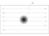
図2に、走査ミラー103の走査線の例を示す。図2に示されるとおり、走査ミラーによって走査される反射光の位置が、走査ミラー103を駆動させることによって、位置aから位置bへと移動する。次に、走査ミラーによって走査される反射光の位置は、位置cから位置dへと移動する。同様に、走査ミラーによって走査される反射光の位置は、位置eから位置fへ、位置gから位置hへ、位置iから位置jへ、そして、位置kから位置lへと移動する。このように、走査ミラー103によって走査される反射光の反射位置は、二次元的に移動されうる。位置eから位置fへの走査線上及び位置gから位置hへの走査線上で、眼球(又は瞳孔)150で反射した反射光が検出される。眼球150の位置が変わることに応じて、眼球150で反射した反射光が検出される走査線又は走査線上の位置が変わりうる。
FIG. 2 shows an example of scanning lines of the
検出部104は、走査ミラー103で反射された反射光162を検出する。検出部104は、例えばフォトダイオードを含む。検出部104の種類は、検出されるべき光の種類に応じて、当業者により適宜選択されてよい。例えば反射光162が赤外光である場合、検出部104は赤外線センサを含む。
検出部104は、例えば反射光162の強度を検出しうる。反射光162が反射された眼球150の位置によって、反射光162の強度は異なる。例えば、瞳孔部分で反射された反射光の強度は、虹彩部分で反射された反射光の強度と異なる。また、眼球の表面(例えば角膜)で反射された反射光の強度は、眼球の眼底(例えば網膜)によって反射された散乱光よりも強い。そのため、走査ミラー103の面の向き又は走査振角と、検出部104により検出された光強度とに基づき、瞳孔位置及び/又は視線方向を推定することができる。
また、他の実施態様において、検出部104は、検出された反射光162に基づき、画像を生成してもよい。例えば、検出部104は、反射光162に基づく画像を生成するために、例えばCMOS又はCCDなどのイメージセンサ、特には赤外線イメージセンサを含みうる。例えば制御部105が、反射光162に基づき生成された画像を画像処理することで、眼球に関する情報(例えば瞳孔位置又は視線方向など)が取得されうる。
検出部104は、制御部105と接続されていてよい。検出部104により検出された光に関する情報、例えば強度などが制御部105によって処理されうる。
例えば、情報検出装置100がメガネ状装置である場合、検出部104は当該メガネ状装置のテンプルのいずれかの位置に取り付けられていてよく、又は、テンプルに含まれるように設けられていてもよい。The
The
Also, in another embodiment, the
The
For example, when the
制御部105は、検出部104によって検出された反射光(例えば反射光の強度など)に基づき、前記眼球に関する情報(例えば瞳孔位置、視線方向、又は眼球の回転角度など)を取得しうる。例えば制御部105は、当該反射光に基づき、前記眼球の瞳孔位置又は視線方向の推定処理を行いうる。
また、制御部105は、走査ミラー103を制御できるように、走査ミラー103と接続されていてよい。例えば、制御部105は、所定の走査振角の範囲内で、走査ミラー103を駆動させうる。制御部105は、走査ミラー103に関する情報、例えば走査ミラーの面の向き又は走査振角など、に関する情報を取得することができる。
好ましくは、制御部105は、走査ミラー103に関する情報と検出部104によって検出された反射光に関する情報とに基づき、眼球に関する情報を取得しうる。例えば、制御部105は、走査ミラー103の走査振角と検出部104によって検出された反射光(特には反射光の強度)とに基づき、例えば瞳孔位置、視線方向、又は眼球の回転角度などの推定処理を行いうる。The
Also, the
Preferably, the
制御部105は、例えばCPUなどのプロセッサ、並びに、例えばRAM及び/又はROMなどのメモリを含みうる。メモリに、本技術に従う情報検出方法又は映像投影方法を装置に実行させるためのプログラムなどが記憶されうる。プロセッサにより、制御部105の機能が実現されうる。
制御部105は、照射部101による光の照射を制御しうる。例えば、制御部105は、照射部101による光の照射のオン若しくはオフを切り替え、又は、照射される光の強度又は種類を変更しうる。また、制御部105は、走査ミラー103の駆動を制御しうる。例えば、制御部105は、走査ミラー103の走査振角を変更しうる。また、制御部105は、検出部104による検出を制御しうる。例えば、制御部105は、検出部104による検出動作のオン又はオフを切り替えうる。
例えば、情報検出装置100がメガネ状装置である場合、制御部105は当該メガネ状装置のテンプルに含まれるように設けられていてもよく、又は、当該メガネ状装置とは別の装置内に設けられており且つ当該メガネ状装置と有線又は無線で接続されていてもよい。The
The
For example, when the
例えば、走査ミラー103の面が図1の左に示されるとおりの方向を向いている場合、眼球150上の位置171を通る反射光(例えば表面反射光又は角膜反射光などを含む)が、走査ミラー103によって反射され、そして検出部104によって検出される。走査ミラー103の面の向きが図1の右に示されるとおりの方向へと変更された場合、眼球150の位置172を通る反射光(例えば虹彩で反射した散乱光など)が、走査ミラー103によって反射され、そして検出部104によって検出される。位置171を通る反射光と位置172を通る反射光の強度は異なる。このように、走査ミラー103の面の向きによって、検出部104に到達する反射光の眼球150上の反射位置が異なる。そのため、走査ミラー103を駆動させることで、眼球150上の種々の位置で反射した反射光に関する情報を取得することができる。
For example, if the plane of
取得された反射光に関する情報は、例えば走査ミラー103の面の向き又は走査振角に対応する。そのため、取得された光に関する情報と走査ミラー103の面の向き又は走査振角とに基づき、眼球150に関する情報を取得することができる。
The acquired information about the reflected light corresponds to, for example, the orientation of the surface of the
また、情報検出装置100の照射部101からの光は、下記「(3)第1の実施形態の第2の例(情報検出装置)」で述べる情報検出装置300の場合と異なり、走査ミラー又はハーフミラーを介さずに眼球に照射される。そのため、情報検出装置100の照射部101からの光の利用効率は、情報検出装置300における照射部301からのものよりも高くすることができる。また、情報検出装置100は、走査ミラー又はハーフミラーに起因する迷光による影響を受けにくい。
Further, the light from the
(3)第1の実施形態の第2の例(情報検出装置) (3) Second example of the first embodiment (information detection device)
以下で、本技術に従う情報検出装置の他の例を、図3を参照しながら説明する。図3は、本技術に従う情報検出装置の模式図である。当該模式図において、当該情報検出装置により情報検出を行うための光の進行方向が矢印により示されている。 Another example of the information detection device according to the present technology will be described below with reference to FIG. FIG. 3 is a schematic diagram of an information detection device according to the present technology. In the schematic diagram, the direction of travel of light for detecting information by the information detection device is indicated by an arrow.
図3に示されるとおり、情報検出装置300は、照射部301、導光部302、走査ミラー303、検出部304、及び制御部305を備えている。情報検出装置300は、さらにハーフミラー306を備えている。これらの構成要素のうち、走査ミラー303、検出部304、及び制御部305は、上記「(2)第1の実施形態の第1の例(情報検出装置)」で述べた走査ミラー103、検出部104、及び制御部105と同じである。情報検出装置100は、照射部101により照射される光を走査ミラー103を介さないで眼球に照射するように構成されているのに対し、情報検出装置300は、照射部301により照射される光が走査ミラー303を介して眼球に照射される。そのため、以下では主に照射部301及び導光部302について説明する。
As shown in FIG. 3 , the
照射部301は、走査ミラー303を介して光361を眼球に対して照射するように構成されている。すなわち、光361は、走査されて眼球に照射される。
好ましくは、光361は、ビーム状の光(特にはレーザ光)として照射部301から照射されてよい。より好ましくは、照射部301は、ビーム状の赤外光を照射する。照射部301は、例えば赤外レーザ光を照射するものであってよい。これにより、例えば瞳孔部分から出る反射光をより明確に検出することができる。そのため、瞳孔位置をより正確に推定することができる。
照射部301により照射された光361は、ハーフミラー306によって反射されて走査ミラー303に到達し、走査ミラー303によってさらに反射されて導光部302に到達し、そして、導光部302によってさらに反射されて眼球に到達する。
例えば、情報検出装置300がメガネ状装置である場合、照射部301は当該メガネ状装置のテンプルのいずれかの位置に取り付けられていてよく、又は、テンプルに含まれるように設けられていてもよい。また、照射部301は、制御部305により制御可能に制御部305と接続されていてよい。
ハーフミラー306は、照射部301からの光を反射し且つ眼球からの反射光を透過する特性を有しうる。検出部304は、走査ミラー303で反射されそしてハーフミラー306を透過した反射光362を検出する。The
Preferably, the light 361 may be emitted from the
For example, when the
The
導光部302は、照射部301から照射された光361を反射し且つ眼球からの反射光362を反射する特性を有するものであってよい。導光部302によって、眼球からの反射光362が走査ミラー303に向けて反射される。上記特性を有する素子として、例えばホログラフィック光学素子を挙げることができる。
導光部302は、例えばグレーティング又はグレーティングレンズであってもよい。導光部302がグレーティングである場合、所定の波長を有する光のみを選択的に反射することができる。導光部302がグレーティングレンズである場合、所定の波長を有する光のみを選択的に反射し且つ眼球に向けて光を集光させることができる。
また、情報検出装置300は、走査ミラー303と導光部302との間に、コリメートレンズなどの他の光学素子をさらに含んでもよい。The
走査ミラー303は、例えばMEMSミラーであってよい。走査ミラー303は、上記のとおり、照射部301により照射された光361を走査し、且つ、眼球での反射された反射光362を走査する。すなわち、本例における情報検出装置300は、照明光を走査する走査ミラー303によって、眼球からの反射光が走査される。
例えば、走査ミラー303の面が図3の左に示されるとおりの方向を向いている場合、眼球上の位置371を通る反射光(例えば表面反射光又は角膜反射光など)が、走査ミラー303によって反射され、そして検出部304によって検出される。走査ミラー303の面の向きが図1の右に示されるとおりの方向へと変更された場合、眼球上の位置372を通る反射光(例えば虹彩で反射した散乱光など)が、走査ミラー303によって反射され、そして検出部304によって検出される。位置371を通る反射光と位置372を通る反射光の強度は異なる。このように、走査ミラー303の面の向きによって、検出部304に到達する反射光の眼球上の反射位置が異なる。そのため、走査ミラー303を駆動させることで、眼球上の種々の位置で反射した反射光に関する情報を取得することができる。
For example, if the plane of
取得された光に関する情報は、例えば走査ミラー303の面の向き又は走査振角に対応する。そのため、取得された光に関する情報と走査ミラー303の面の向き又は走査振角とに基づき、眼球に関する種々の情報を取得することができる。
The acquired information about the light corresponds to, for example, the orientation of the surface of the
情報検出装置300は、眼球に照射される光及び反射光の進路上の光学系(例えば走査ミラー)が共有される。そのため、情報検出装置300は、上記「(2)第1の実施形態の第1の例(情報検出装置)」で述べた情報検出装置100よりも小型化することができる。
また、情報検出装置300の照射部301からの光は、ハーフミラー306及び走査ミラー303を介して眼球に照射される。そのため、当該光の利用効率が、上記「(2)第1の実施形態の第1の例(情報検出装置)」で述べた情報検出装置100よりも低くなる場合がある。しかしながら、ハーフミラー306及び走査ミラー303それぞれの光の透過率又は反射率を上げることで、当該光の利用効率を上げることができる。The
Also, the light from the
2.第2の実施形態(映像投影装置) 2. Second embodiment (video projection device)
(1)第2の実施形態の説明 (1) Description of the second embodiment
本技術に従う映像投影装置は、上記「1.第1の実施形態(情報検出装置)」で説明した構成要素に加えて、前記制御部により推定された瞳孔位置を映像表示光が通過するように映像表示光を照射する映像表示光照射部を備えている。
本技術に従う映像投影装置は、上記「1.第1の実施形態(情報検出装置)」で述べた効果を奏する。さらに、本技術に従う映像投影装置は、映像表示光を適切な位置に照射することができるという効果を奏する。A video projection device according to the present technology has, in addition to the components described in “1. First Embodiment (Information Detecting Device)” above, a video display light that passes through the pupil position estimated by the control unit. An image display light irradiation unit for irradiating image display light is provided.
The image projection device according to the present technology has the effects described in the above “1. First embodiment (information detection device)”. Furthermore, the video projection device according to the present technology has the effect of being able to irradiate the video display light onto an appropriate position.
(2)第2の実施形態の第1の例(映像投影装置) (2) First example of the second embodiment (video projection device)
以下で、本技術に従う映像投影装置の例を、図4を参照しながら説明する。図4は、本技術に従う映像投影装置の模式図である。当該模式図において、当該映像投影装置により情報検出を行うための光の進行方向及び映像表示光の方向が点線の矢印により示されている。 An example of a video projection device according to the present technology will be described below with reference to FIG. FIG. 4 is a schematic diagram of a video projection device according to the present technology. In the schematic diagram, the direction of travel of light for information detection by the image projection device and the direction of image display light are indicated by dotted arrows.
図4に示されるとおり、映像投影装置400は、照射部401、導光部402、走査ミラー403、検出部404、及び制御部405を備えている。映像投影装置400はさらに、映像表示光照射部420を備えている。これらの構成要素のうち、照射部401、走査ミラー403、検出部404、及び制御部405は、上記1.の「(2)第1の実施形態の第1の例(情報検出装置)」で述べた照射部101、走査ミラー103、検出部104、及び制御部105と同じである。そのため、上記1.の「(2)第1の実施形態の第1の例(情報検出装置)」で述べたとおりの情報(例えば瞳孔位置)を検出することができる。
映像投影装置400は、上記1.の「(2)第1の実施形態の第1の例(情報検出装置)」において説明した情報検出装置100に、映像表示光照射部420が追加された装置である。以下では、主に導光部402及び映像表示光照射部420について説明する。As shown in FIG. 4 , the
The
導光部402は、照射部401から照射された照明光を透過し且つ眼球からの反射光を反射する特性を有しうる。照射部401から照射される光が平行光でない場合、導光部402は好ましくは当該光を平行化させる光学特性を有しうる。
さらに、導光部402は、映像表示光照射部420により照射された映像表示光を反射する特性を有するものであってよい。導光部402は、好ましくは映像表示光照射部420から照射された映像表示光が瞳孔付近に集光されそして網膜に照射されるように、当該映像表示光を反射する。すなわち、映像表示光が瞳孔を直進するように、導光部402は映像表示光を回折しうる。これにより、いわゆるマクスウェル視によりユーザに映像を提示することができる。そのため、鮮明な映像をユーザに提示することができる。
本技術において、映像表示光は瞳孔付近で集光されてよく、例えば瞳孔上で集光されてもよく又は光軸方向に瞳孔から数mm~十数mm程度(例えば1mm~20mm、特には2mm~15mm)ずれてもよい。後者のとおり焦点が瞳孔上になくても、マックスウェル視を実現することができる。焦点を光軸方向にずらすことで、映像がずれても、ユーザが映像を失いにくくすることができる。前記映像表示光は、より具体的には、瞳孔上、水晶体レンズ内、又は、角膜表面と瞳孔との間において集光されうる。
例えば映像投影装置400がメガネ状装置である場合、導光部102は例えば当該メガネ状装置のレンズ自体であってよく、又は、レンズの一部として構成されていてもよい。The
Furthermore, the
In the present technology, the image display light may be condensed in the vicinity of the pupil, for example, may be condensed on the pupil, or about several mm to ten and several mm (eg, 1 mm to 20 mm, particularly 2 mm) from the pupil in the optical axis direction. ~15 mm). Maxwell vision can be achieved even if the focal point is not on the pupil as in the latter case. By shifting the focal point in the optical axis direction, it is possible to prevent the user from losing the image even if the image is shifted. The image display light can be more specifically focused on the pupil, within the crystalline lens, or between the corneal surface and the pupil.
For example, when the
映像表示光照射部420は、映像表示光を導光部402に向けて照射する。照射される映像表示光は、放射状に照射されうる。映像表示光照射部420は、制御部405によって制御されうる。例えば、制御部405は、制御部405により推定された瞳孔位置にて映像表示光が集光するように、映像表示光照射部420による映像表示光の照射を制御しうる。これにより、ユーザに映像をより確実に提示することができる。
映像表示光は、例えばマクスウェル視によりユーザに映像を提示することができるものでありうる。映像表示光は、例えばLED又はCRTにより照射される光であってよい。
例えば映像投影装置400がメガネ状装置である場合、映像表示光照射部420は例えば当該メガネ状装置のテンプル部分に取り付けられてよく、又は、テンプル部分に含まれてもよい。映像表示光照射部420により映像がユーザに提示されることによって、当該メガネ状装置のレンズを介してユーザが見る外界風景に当該映像が重畳される。The image display
The image display light may be capable of presenting an image to the user, for example, in Maxwell's vision. The image display light may be light emitted by an LED or a CRT, for example.
For example, if the
(3)第2の実施形態の第2の例(映像投影装置) (3) Second example of the second embodiment (video projection device)
本技術に従う映像投影装置の他の例を、図5を参照しながら説明する。図5は、本技術に従う映像投影装置の模式図である。当該模式図において、本技術に従い情報検出を行うための光の進行方向及び映像表示光の進行方向が点線の矢印により示されている。 Another example of a video projection device according to the present technology will be described with reference to FIG. FIG. 5 is a schematic diagram of a video projection device according to the present technology. In the schematic diagram, the direction of travel of light for detecting information according to the present technology and the direction of travel of image display light are indicated by dotted arrows.
図5に示されるとおり、映像投影装置500は、照射部501、導光部502、走査ミラー503、検出部504、及び制御部505を備えている。映像投影装置500は、さらにハーフミラー506及び映像表示光照射部520を備えている。
これらの構成要素のうち、照射部501、導光部502、走査ミラー503、検出部504、制御部505、及びハーフミラー506は、上記1.の「(3)第1の実施形態の第2の例(情報検出装置)」において説明した照射部301、導光部302、走査ミラー303、検出部304、制御部305、及びハーフミラー306に対応する。そのため、上記1.の「(3)第1の実施形態の第2の例(情報検出装置)」で述べたとおりの情報(例えば瞳孔位置)を検出することができる。
映像投影装置500は、上記1.の「(3)第1の実施形態の第2の例(情報検出装置)」において説明した情報検出装置300に、映像表示光照射部520が追加された装置であるともいえる。以下では、主に導光部502及び映像表示光照射部520について説明する。As shown in FIG. 5 , the
Among these components, the
The
導光部502は、照射部501から照射された照明光を反射し且つ眼球からの反射光を反射する特性を有しうる。
The
さらに、導光部502は、映像表示光照射部520により照射された映像表示光を反射する特性を有しうる。導光部502は、好ましくは映像表示光照射部520から照射された映像表示光が瞳孔付近に集光されそして網膜に照射されるように、当該映像表示光を反射する。すなわち、映像表示光が瞳孔を直進するように、導光部502は映像表示光を回折しうる。これにより、いわゆるマクスウェル視によりユーザに映像を提示することができる。そのため、鮮明な映像をユーザに提示することができる。
Furthermore, the
映像表示光照射部520は、映像表示光を導光部502に向けて照射する。照射される映像表示光は、放射状に照射されうる。映像表示光照射部520は、制御部505によって制御されうる。例えば、制御部505は、制御部505により推定された瞳孔位置にて映像表示光が集光するように、例えば映像表示光照射部520による映像表示光の照射を制御しうる。これにより、ユーザに映像をより確実に提示することができる。映像表示光は、例えばマクスウェル視によりユーザに映像を提示することができるものでありうる。映像表示光は、例えばLED又はCRTにより照射される光であってよい。
例えば映像投影装置500がメガネ状装置である場合、映像表示光照射部520は例えば当該メガネ状装置のテンプル部分に取り付けられてよく、又は、テンプル部分に含まれてもよい。映像表示光照射部520により映像がユーザに提示されることによって、当該メガネ状装置のレンズを介してユーザが見る外界風景に当該映像が重畳される。The image display
For example, if the
(4)第2の実施形態の第3の例(映像投影装置) (4) Third example of the second embodiment (video projection device)
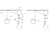
本技術に従う映像投影装置の他の例を、図6を参照しながら説明する。図6は、本技術に従う映像投影装置の模式図である。当該模式図において、当該映像投影装置により情報検出を行うための光の進行方向及び映像表示光の進行方向が点線の矢印により示されている。 Another example of a video projection device according to the present technology will be described with reference to FIG. FIG. 6 is a schematic diagram of a video projection device according to the present technology. In the schematic diagram, the direction of travel of light for detecting information by the image projection device and the direction of travel of image display light are indicated by dotted arrows.
図6に示されるとおり、映像投影装置600は、照射部601、導光部602、走査ミラー603、検出部604、及び制御部605を備えている。映像投影装置600はさらにハーフミラー606を備えている。
As shown in FIG. 6 , the
照射部601は、走査ミラー603を介して照明光661を眼球650に対して照射するように構成されている。すなわち、照明光661は、走査されて眼球に照射される。
好ましくは、照明光661は、ビーム状の光として照射部601から照射されてよい。より好ましくは、照射部601は、ビーム状の赤外光、特には赤外線レーザ光を照射する。
照射部601により照射された照明光661は、ハーフミラー606によって反射されて走査ミラー603に到達し、走査ミラー603によってさらに反射されて導光部602に到達し、そして、導光部602によってさらに反射されて眼球650に到達する。
照射部601は、照明光661に加えて、映像表示光663を照射することができるように構成されている。例えば、照明光661及び映像表示光663は、合波された状態で照射部601により出力されてよい。映像表示光663によって、ユーザに映像が提示される。
照射部601は、例えば映像表示光及び照明光が合波されたレーザ光、特には赤、緑、及び青のレーザ光及び赤外線レーザ光が合波されたレーザ光を出力しうる。
例えば映像投影装置600がメガネ状装置である場合、照射部601は当該メガネ状装置のテンプルのいずれかの位置に取り付けられていてよく、又は、テンプルに含まれるように設けられていてもよい。照射部601により映像がユーザに提示されることによって、当該メガネ状装置のレンズを介してユーザが見る外界風景に当該映像が重畳される。The
Preferably, the
The
The
For example, when the
導光部602は、照射部601から照射された照明光661及び映像表示光663を反射し且つ眼球からの反射光662を反射する特性を有するものであってよい。導光部602は、好ましくは、照明光661が眼球上の走査されるべき位置に到達するように反射し且つ映像表示光663が瞳孔位置で集光されて(特には瞳孔の中心を通って)網膜に照射されるように反射する特性を有しうる。これらの特性を有する導光部として、当技術分野で公知の光学素子を用いることができる。当該光学素子として、例えばホログラフィック光学素子を挙げることができる。
例えば図6の左に示されるとおり、導光部602の位置673に照明光661及び映像表示光663が到達した場合、照明光661及び映像表示光663のいずれもが瞳孔の中心671を通るように反射される。例えば図6の右に示されるとおりに、導光部602の位置674に照明光661及び映像表示光663が到達した場合、照明光661は瞳孔の中心からはずれた位置672に照射されるように反射され、及び、映像表示光663は、瞳孔の中心671を通るように反射される。The
For example, as shown on the left side of FIG. 6, when the
走査ミラー603は、例えばMEMSミラーであってよい。走査ミラー603は、上記のとおり、照射部601により照射された照明光661及び映像表示光663(又はこれらの合波)を走査し、且つ、眼球650での反射された反射光662を走査する。すなわち、本例における映像投影装置600において、照明光を走査する走査ミラーによって、眼球反射光及び映像表示光も走査される。
照明光が眼球に照射されることで、反射光が生じ、そして、当該反射光を走査することで、眼球に関する情報を取得することができる。
また、映像表示光が網膜上に走査されることにより、ユーザに映像が提示される。映像表示光は、当該走査によって、例えば瞳孔付近に集光されそして網膜に照射される。すなわち、映像表示光が瞳孔を直進する。これにより、いわゆるマクスウェル視によりユーザに映像を提示することができる。そのため、鮮明な映像をユーザに提示することができる。
By irradiating the eyeball with the illumination light, reflected light is generated, and by scanning the reflected light, information about the eyeball can be obtained.
In addition, an image is presented to the user by scanning the retina with the image display light. The image display light is focused, for example, near the pupil by the scanning and projected onto the retina. That is, the image display light travels straight through the pupil. Accordingly, it is possible to present an image to the user by so-called Maxwell's vision. Therefore, a clear image can be presented to the user.
例えば、走査ミラー603の面が図6の左に示されるとおりの方向を向いている場合、眼球650の中心671を通る反射光(例えば表面反射光又は角膜反射光などを含む)が、導光部602そして走査ミラー603によって反射され、ハーフミラー606を透過し、そして検出部604によって検出される。走査ミラー603の面の向きが図6の右に示されるとおりの方向へと変更された場合、眼球650の位置672を通る反射光(例えば虹彩で反射した散乱光などを含む)が、導光部602そして走査ミラー603によって反射され、ハーフミラー606を透過し、そして検出部604によって検出される。このように、走査ミラー603の面の向きによって、検出部604に到達する反射光が反射される眼球650上の位置が異なり、反射される眼球上の位置によって反射光の強度は異なる。そのため、走査ミラー603を駆動させることで、眼球650上の種々の位置で反射した反射光に関する情報を取得することができる。
For example, if the surface of
検出部604は、走査ミラー603で反射されそしてハーフミラー606を透過した反射光662を検出する。
The
制御部605は、検出部604によって検出された反射光に関する情報(例えば反射光の強度など)を処理しうる。例えば制御部605は、当該反射光に関する情報に基づき、眼球についての情報(例えば眼球の回転角度、瞳孔の位置、及び視線の方向など)を取得しうる。好ましくは、制御部605は、検出部604により検出された反射光に基づき、前記眼球の瞳孔位置の推定処理を行いうる。
また、制御部605は、走査ミラー603を制御可能に構成されていてよい。例えば、制御部605は、所定の走査振角の範囲内で、走査ミラー603を駆動させうる。制御部605は、走査ミラー603に関する情報、例えば走査ミラーの面の向き又は走査振角など、に関する情報を取得することができる。
好ましくは、制御部605は、走査ミラー603に関する情報と検出部604によって検出された反射光に関する情報とに基づき、眼球についての情報を取得しうる。例えば、制御部605は、走査ミラー603の走査振角と検出部604によって検出された反射光(例えば反射光の強度)とに基づき、瞳孔位置、視線方向、又は眼球の回転角度を推定しうる。
また、制御部605は、取得された眼球についての情報に基づき、照射部601を制御して、照射される映像表示光を調整しうる。これにより、ユーザの視野中の適切な位置に映像を表示することができる。The
Also, the
Preferably, the
Further, the
制御部605は、例えばCPUなどのプロセッサ、並びに、例えばRAM及び/又はROMなどのメモリを含みうる。メモリに、本技術に従う情報検出方法又は映像投影方法を装置に実行させるためのプログラムなどが記憶されうる。プロセッサにより、制御部605の機能が実現されうる。
制御部605は、照射部601による照明光及び/又は映像表示光の照射を制御しうる。例えば、制御部605は、照射部601による照明光及び又は映像表示光の照射のオン若しくはオフを切り替え、又は、照射される照明光及び又は映像表示光の強度又は種類を変更しうる。また、制御部605は、走査ミラー603の駆動を制御しうる。例えば、制御部605は、走査ミラー603の走査振角を変更しうる。また、制御部605は、検出部604による検出を制御しうる。例えば、制御部605は、検出部604による検出動作のオン又はオフを切り替えうる。The
The
ハーフミラー606は、照明光661及び映像表示光663(又はこれらの合波)を反射し且つ反射光662を透過する特性を有しうる。これにより、反射光662だけを選択的に検出部604に到達させることができる。
The
映像投影装置600は、上記のとおり照射部601が照明光及び映像表示光を照射することができるように構成されているので、当該装置を小型化することが可能である。また、照明光、映像表示光、及び反射光の経路上の光学系(例えば走査ミラーなど)が共有されているので、当該装置をさらに小型化することができる。
Since the
3.第3の実施形態(情報検出方法) 3. Third Embodiment (Information Detection Method)
(1)第3の実施形態の説明 (1) Description of the third embodiment
本技術は、眼球に光を照射する照射工程と、前記眼球からの反射光を走査ミラーによって走査する走査工程と、前記走査ミラーにより走査された反射光を検出する検出工程と、を含む情報検出方法も提供する。
本技術に従う情報検出方法によって、上記1.で述べたとおりの眼球の情報を検出することができる。The present technology includes an irradiation step of irradiating an eyeball with light, a scanning step of scanning reflected light from the eyeball with a scanning mirror, and a detection step of detecting the reflected light scanned by the scanning mirror. We also provide a method.
By the information detection method according to the present technology, the above 1. It is possible to detect eyeball information as described in .
(2)第3の実施形態の例(情報検出方法) (2) Example of the third embodiment (information detection method)
以下で、本技術に従う情報検出方法の例を図1及び図7を参照しながら説明する。図7は、本技術に従う情報検出方法のフローの一例を示す図である。 An example of an information detection method according to the present technology is described below with reference to FIGS. 1 and 7. FIG. FIG. 7 is a diagram illustrating an example flow of an information detection method according to the present technology.
ステップS101において、情報検出装置100は、本技術に従う情報検出処理を開始する。
In step S101, the
ステップS102において、制御部105が、照射部101に照明光を眼球に照射させる。照射される光は、好ましくは非可視光であり、より好ましくは赤外光である。照明光は、例えば瞳孔位置の検出が必要な場合のみ照射されてよく、又は、所定の時間間隔で照射されてもよい。
In step S102, the
ステップS103において、制御部105が走査ミラー103を駆動して、ステップS102における照明光の眼球への照射により生じた反射光を走査ミラー103により走査させる。当該走査の結果、眼球の種々の位置のそれぞれで反射された反射光が検出部104に進む。
In step S103, the
ステップS104において、制御部105は、検出部104に、ステップS103において走査された反射光を検出させる。当該検出の結果、当該反射光に関する情報、例えば反射光の強度などが取得されうる。
In step S104, the
ステップS105において、制御部105が、ステップS104において取得された前記反射光に関する情報とステップS103における走査に関する情報とに基づき、眼球に関する情報を取得する。
In step S105, the
ステップS106において、情報検出装置100は、本技術に従う情報検出処理を終了する。
以上の処理が、例えば本技術に従う情報検出装置又は映像投影装置により行われうる。上記の各ステップにおけるこれら装置の各構成要素のより詳細な動作については、上記「1.第1の実施形態(情報検出装置)」及び「2.第2の実施形態(映像投影装置)」を参照されたい。In step S106, the
The above processing may be performed, for example, by an information detection device or a video projection device according to the present technology. For more detailed operation of each component of these devices in each of the above steps, see "1. First embodiment (information detection device)" and "2. Second embodiment (video projection device)" above. Please refer to
4.第4の実施形態(映像投影方法) 4. Fourth Embodiment (Video Projection Method)
(1)第4の実施形態の説明 (1) Description of the fourth embodiment
本技術は、眼球に光を照射する照射工程と、前記眼球からの反射光を走査ミラーによって走査する走査工程と、前記走査ミラーにより走査された反射光を検出する検出工程と、前記検出工程において検出された反射光に基づき、前記眼球の瞳孔位置を推定する推定工程と、前記推定工程において推定された瞳孔位置を映像表示光が通過するように映像表示光を照射する映像表示光照射工程とを含む映像投影方法も提供する。
本技術に従う映像投影方法によって、上記1.で述べたとおりの眼球の情報を検出することができる。さらに、本技術に従う映像投影方法により、検出された眼球の情報に基づき、的確な位置に映像表示光を照射することができる。The present technology includes an irradiation step of irradiating an eyeball with light, a scanning step of scanning reflected light from the eyeball with a scanning mirror, a detection step of detecting the reflected light scanned by the scanning mirror, and the detection step. an estimating step of estimating the pupil position of the eyeball based on the detected reflected light; and an image display light irradiation step of irradiating the image display light so that the image display light passes through the pupil position estimated in the estimation step. A method for projecting an image is also provided.
By the video projection method according to the present technology, the above 1. It is possible to detect eyeball information as described in . Furthermore, with the image projection method according to the present technology, it is possible to irradiate the image display light to an accurate position based on the detected eyeball information.
(2)第4の実施形態の例(映像投影方法) (2) Example of the fourth embodiment (video projection method)
以下で、本技術に従う映像投影方法の例を図6及び図8を参照しながら説明する。図8は、本技術に従う映像投影方法のフローの一例を示す図である。 An example of a video projection method according to the present technology will be described below with reference to FIGS. 6 and 8. FIG. FIG. 8 is a diagram illustrating an example flow of a video projection method according to the present technology.
ステップS201において、映像投影装置600は、本技術に従う映像投影処理を開始する。
In step S201, the
ステップS202において、制御部605が、照射部601に照明光を眼球に照射させる。照射される光は、好ましくは非可視光であり、より好ましくは赤外光である。照明光は、例えば瞳孔位置の検出が必要な場合のみ照射されてよく、又は、所定の時間間隔をあけて照射されてもよい。
In step S202, the
ステップS203において、制御部605が走査ミラー603を駆動して、ステップS202における照明光の眼球への照射により生じた反射光を走査ミラー603により走査させる。当該走査の結果、眼球の種々の位置のそれぞれで反射された反射光が検出部604に進む。
In step S203, the
ステップS204において、制御部605は、検出部604に、ステップS203において走査された反射光を検出させる。当該検出の結果、当該反射光に関する情報、例えば反射光の強度などが取得されうる。
In step S204, the
ステップS205において、制御部605は、ステップS204において取得された前記反射光に関する情報とステップS203における走査に関する情報とに基づき、眼球に関する情報を取得する。
In step S205, the
ステップS206において、制御部605は、ステップS205において取得された前記眼球に関する情報(例えば瞳孔位置)に基づき調節された映像表示光を、照射部601に照射させる。これにより、眼球に映像表示光が照射されて、ユーザが映像を認識することができる。
In step S206, the
ステップS207において、映像投影装置600は、本技術に従う映像投影処理を終了する。
以上の処理が、例えば本技術に従う映像投影装置により行われうる。上記の各ステップにおける当該装置の各構成要素のより詳細な動作については、上記「2.第2の実施形態(映像投影装置)」を参照されたい。In step S207, the
The above processing may be performed, for example, by a video projection device according to the present technology. For more detailed operations of each component of the apparatus in each step above, see "2. Second Embodiment (Video Projection Apparatus)" above.
5.装置の構成例 5. Device configuration example
本技術に従う映像投影装置の具体的な例を図9及び10を参照しながら以下で説明する。 A specific example of a video projection device according to the present technology is described below with reference to FIGS. 9 and 10. FIG.
図9は、本技術に従う映像投影装置の一例としてのヘッドマウントディスプレイ(以下、HMDという)900を示す。HMD900は、ネガネ状装置であり、すなわちアイウェアディスプレイとも言える。
HMD900のノーズパッド951内に、本技術に従う情報検出を行うための主な構成要素が設けられている。すなわち、HMD900のノーズパッド951内に、照射部901、ハーフミラー906、走査ミラー903、検出部904、及び制御部905が設けられている。なお、制御部905は、ノーズパッド951内でなく、例えばテンプル953内に設けられていてもよい。
HMD900のテンプル953内に、本技術に従い検出された情報に基づき映像をユーザに提示するための主な構成要素が設けられている。すなわち、HMD900のテンプル953に、映像表示光照射部920が設けられている。映像表示光照射部920は、出力部921、走査ミラー922、レンズ923、及び光学系924を備えている。映像表示光照射部920は、制御部905と接続されうる。
また、HMD900のレンズ952に、導光部902が設けられている。FIG. 9 shows a head mounted display (hereinafter referred to as HMD) 900 as an example of a video projection device according to the present technology. The
Within
Within the
A
照射部901から照射された照明光は、ハーフミラー906及び走査ミラー903により反射されて、導光部902に到達する。照明光は、導光部902によりさらに反射されて眼球に到達する。眼球からの反射光が、導光部902により反射され、走査ミラー903により走査され、そしてハーフミラー906を透過する。ハーフミラー906を透過した反射光が検出部904によって検出される。検出された反射光に関する情報と、例えば走査ミラー903に関する情報とに基づき、眼球に関する情報が検出される。当該眼球に関する情報に基づき、映像表示光照射部920は、ユーザが映像を正確に認識できるように、映像表示光を照射する。
The illumination light emitted from the
図10は、本技術に従う映像投影装置としてのHMDの他の例を示す。図100に示されるHMD1000は、メガネ様の形状を有し、すなわちアイウェアディスプレイとも言える。
HMD1000のテンプル1053内に、本技術に従う情報検出を行うための主な構成要素、及び、本技術に従い検出された情報に基づき映像をユーザに提示するための主な構成要素が設けられている。また、HMD1000は、眼球への照明光、眼球からの反射光、及び映像表示光の進路上の光学系が共有されている。すなわち、HMD1000のテンプル1053内に、照射部1001、走査ミラー1003、検出部1004、及び制御部1005が設けられている。さらに、HMD1000のテンプル1053内に、ハーフミラー1006、レンズ1007、及び光学系(例えば反射ミラーなど)1008が設けられている。また、HMD1000のレンズ1052に、導光部1002が設けられている。FIG. 10 shows another example of HMD as a video projection device according to the present technology. The
In the
照射部1001から照射された照明光は、ハーフミラー1006、光学系1008、及び走査ミラー1003を経由して、導光部1002に到達する。照明光は、導光部1002によりさらに反射されて眼球に到達する。眼球からの反射光が、導光部1002により反射され、走査ミラー1003により走査され、光学系1008を経由し、そしてハーフミラー1006を透過する。ハーフミラー1006を透過した反射光が検出部1004によって検出される。検出された反射光に関する情報と、例えば走査ミラー1003に関する情報とに基づき、眼球に関する情報が検出される。当該眼球に関する情報に基づき、照射部1001は、ユーザが映像を正確に認識できるように、映像表示光を照射する。
Illumination light emitted from the
6.実施例 6. Example
(1)実施例1(第1の実施形態の第1の例のシミュレーション) (1) Example 1 (simulation of first example of first embodiment)
上記1.の「(2)第1の実施形態の第1の例(情報検出装置)」において述べた情報検出装置による情報検出を、OpticStudio(商標)(Zemax社)を用いてシミュレーションした。シミュレーションされた装置の構成を図11に示す。図11に示される装置1100は、照射部としての平行光源1101、導光部としてのホログラフィック素子1102、コリメートレンズ1110、走査ミラー1103、及び検出部1104を有する。
1 above. Information detection by the information detection device described in "(2) First Example of First Embodiment (Information Detection Device)" was simulated using OpticStudio (trademark) (Zemax). The configuration of the simulated device is shown in FIG. A
眼球が瞳孔部に対して正面を向き且つ走査ミラー1103の走査振角が-10度~10度である場合において検出部1104によって検出される眼球からの反射光の光強度を、シミュレーションにより得た。走査振角と当該光強度との関係を図15に示す。
また、眼球が正面を向いている場合を0度とし、眼球が5度又は10度回転した場合においても、同様に走査振角が-10度~10度である場合において検出される反射光の光強度を得た。眼球が5度又は10度回転した場合に得られた光強度と走査振角との関係も図12に示す。The light intensity of the reflected light from the eyeball detected by the
Also, when the eyeball is facing forward, it is 0 degrees, and when the eyeball rotates by 5 degrees or 10 degrees, the reflected light detected when the scanning swing angle is -10 degrees to 10 degrees. Light intensity was obtained. FIG. 12 also shows the relationship between the light intensity and the scanning oscillation angle obtained when the eyeball is rotated by 5 degrees or 10 degrees.
図12に示されるとおり、0超の光強度が取得される場合の走査振角と光強度が0である場合の走査振角との境界(以下、エッジという。図12のa、b、及びc)が、眼球の回転が0度である場合、5度である場合、及び10度である場合とで異なり、眼球の回転角度に応じてエッジが移動している。そのため、走査振角と光強度との関係に基づき、眼球の回転角度、瞳孔位置、又は視線方向を推定することができる。
また、眼球の回転が0度である場合、5度である場合、及び10度である場合を比較すると、眼球の回転角度に応じて、光強度の分布が移動している。そのため、走査振角に対する光強度の分布に基づき、眼球の回転角度、瞳孔位置、又は視線方向を推定することもできる。As shown in FIG. 12, the boundary between the scanning oscillation angle when the light intensity is greater than 0 and the scanning oscillation angle when the light intensity is 0 (hereinafter referred to as edges. In c), the edge moves according to the rotation angle of the eyeball, unlike the cases where the eyeball rotation is 0 degrees, 5 degrees, and 10 degrees. Therefore, the rotation angle of the eyeball, the pupil position, or the line-of-sight direction can be estimated based on the relationship between the scanning oscillation angle and the light intensity.
Further, comparing the cases where the eyeball rotation is 0 degrees, 5 degrees, and 10 degrees, the light intensity distribution moves according to the eyeball rotation angle. Therefore, it is also possible to estimate the rotation angle of the eyeball, the pupil position, or the line-of-sight direction based on the distribution of the light intensity with respect to the scanning swing angle.
上記シミュレーションは、走査ミラーの走査振角が一次元方向に変更された場合の結果である。そのため、走査ミラーの走査振角を二次元方向に変更することで、眼球についての情報(例えば眼球の回転角度、瞳孔位置、及び視線方向など)をより正確に推定することができる。 The above simulation is the result when the scanning swing angle of the scanning mirror is changed in a one-dimensional direction. Therefore, by changing the scanning swing angle of the scanning mirror in two-dimensional directions, it is possible to more accurately estimate information about the eyeball (for example, the rotation angle of the eyeball, the pupil position, the line-of-sight direction, etc.).
(2)実施例2(第1の実施形態の第2の例のシミュレーション) (2) Example 2 (simulation of second example of first embodiment)
上記1.の「(3)第1の実施形態の第2の例(情報検出装置)」において述べた情報検出装置による情報検出を、OpticStudio(商標)(Zemax社)を用いてシミュレーションした。シミュレーションされた装置の構成を図13に示す。図13に示される装置1300は、照射部1301、導光部としてのホログラフィック素子(グレーティング)1302、コリメートレンズ1310、走査ミラー1303、及び検出部1304を有する。さらに、装置1300はハーフミラー1305を有する。
1 above. Information detection by the information detection device described in "(3) Second example of first embodiment (information detection device)" was simulated using OpticStudio (trademark) (Zemax). The configuration of the simulated device is shown in FIG. The
眼球が瞳孔部に対して正面を向いており且つ走査ミラー1303の走査振角が-10度~10度である場合において検出部1304によって検出される眼球からの反射光の光強度を、シミュレーションにより得た。走査振角と当該光強度との関係を図14に示す。
また、眼球が正面を向いている場合を0度とし、眼球が5度又は10度回転した場合においても、同様に走査振角-10度~10度において検出される光強度を得た。眼球が5度又は10度回転した場合に得られた光強度と走査振角との関係も図14に示す。The light intensity of the reflected light from the eyeball detected by the
In addition, the light intensity detected at the scanning swing angle of -10 degrees to 10 degrees was similarly obtained even when the eyeballs were rotated by 5 degrees or 10 degrees, assuming that the eyeballs were facing forward at 0 degrees. FIG. 14 also shows the relationship between the light intensity and the scanning oscillation angle obtained when the eyeball is rotated 5 degrees or 10 degrees.
図14に示されるとおり、エッジ(図14のa、b、及びc)が、眼球の回転が0度である場合、5度である場合、及び10度である場合とで異なり、眼球の回転角度に応じてエッジが移動している。そのため、走査振角と光強度との関係に基づき、眼球の回転角度、瞳孔位置、又は視線方向を推定することができる。
眼球の回転が0度である場合、5度である場合、及び10度である場合を比較すると、眼球の回転角度に応じて、光強度の分布が移動している。そのため、走査振角に対する光強度の分布に基づき、眼球の回転角度、瞳孔位置、又は視線方向を推定することもできる。As shown in FIG. 14, the edges (a, b, and c in FIG. 14) are different from 0 degrees, 5 degrees, and 10 degrees of eye rotation. The edge is moving according to the angle. Therefore, the rotation angle of the eyeball, the pupil position, or the line-of-sight direction can be estimated based on the relationship between the scanning oscillation angle and the light intensity.
When the eyeball rotation is 0 degrees, 5 degrees, and 10 degrees, the light intensity distribution moves according to the eyeball rotation angle. Therefore, it is also possible to estimate the rotation angle of the eyeball, the pupil position, or the line-of-sight direction based on the distribution of the light intensity with respect to the scanning swing angle.
また、眼球の回転が0度である場合、5度である場合、及び10度である場合のそれぞれにおいて、突出したピーク(図14のd)を確認することができる。当該ピークは、角膜の表面反射光及び網膜での散乱光の両方に起因する。また、当該ピークの周辺の領域(図14のe)は、網膜での散乱光に起因する。そのため、当該ピーク及び/又は当該領域に基づき、眼球に関する情報(例えば瞳孔位置、視線方向、又は眼球の回転角度など)をより正確に推定することができる。 In addition, a prominent peak (d in FIG. 14) can be confirmed when the rotation of the eyeball is 0 degrees, 5 degrees, and 10 degrees. The peak is due to both corneal surface reflected light and retina scattered light. Also, the area around the peak (e in FIG. 14) is due to scattered light on the retina. Therefore, based on the peak and/or the region, it is possible to more accurately estimate information about the eyeball (for example, pupil position, line-of-sight direction, eyeball rotation angle, etc.).
装置1300を用いた場合、上記実施例1の装置1100を用いた場合と異なり、当該ピーク及び/又は当該領域を観察することができる。これは主に、眼球に照射される照明光として、ビーム状の光(特にはレーザ光)を用いていることによる。そのため、眼球に光を照射するための照射部として、ビーム状の光を照射する照射部を用いることで、より正確に眼球に関する情報を取得することができる。
When the
(3)実施例3(第1の実施形態の第2の例のシミュレーション) (3) Example 3 (simulation of second example of first embodiment)
上記1.の「(3)第1の実施形態の第2の例(情報検出装置)」において述べた情報検出装置による情報検出を、OpticStudio(商標)(Zemax社)を用いてシミュレーションした。シミュレーションされた装置の構成を図15に示す。図15に示される装置1500は、照射部1501を有し、導光部としてホログラフィック素子(グレーティングレンズ)1502を有し、コリメートレンズ1510を有し、且つ、走査ミラー1503及び検出部1504を有する。さらに、装置1500はハーフミラー1505を有する。
ホログラフィック素子1502は、実施例2と異なり、グレーティングレンズであり、すなわち集光特性を有する。当該集光特性によって、照射部からの照明光が瞳孔に向けて集光される。1 above. Information detection by the information detection device described in "(3) Second example of first embodiment (information detection device)" was simulated using OpticStudio (trademark) (Zemax). The configuration of the simulated device is shown in FIG. The
The
眼球が瞳孔部に対して正面を向いており且つ走査ミラー1503の走査振角が-10度~10度である場合において検出部1504によって検出される眼球からの反射光の光強度を、シミュレーションにより得た。走査振角と当該光強度との関係を図16に示す。
また、眼球が正面を向いている場合を0度とし、眼球が5度又は10度回転した場合においても、同様に走査振角-10度~10度において検出される光強度を得た。眼球が5度又は10度回転した場合に得られた光強度と走査振角との関係も図16に示す。The light intensity of the reflected light from the eyeball detected by the
In addition, the light intensity detected at the scanning swing angle of -10 degrees to 10 degrees was similarly obtained even when the eyeballs were rotated by 5 degrees or 10 degrees, assuming that the eyeballs were facing forward at 0 degrees. FIG. 16 also shows the relationship between the light intensity and the scanning swing angle obtained when the eyeball is rotated by 5 degrees or 10 degrees.
図16に示されるとおり、エッジ(図16のa、b、及びc)が、眼球の回転が0度である場合、5度である場合、及び10度である場合とで異なり、眼球の回転角度に応じてエッジが移動している。そのため、走査振角と光強度との関係に基づき、眼球の回転角度、瞳孔位置、又は視線方向を推定することができる。
また、眼球の回転が0度である場合、5度である場合、及び10度である場合を比較すると、眼球の回転角度に応じて、光強度の分布が移動している。そのため、光強度の分布によって、眼球の回転角度、瞳孔位置、又は視線方向を推定することもできる。As shown in FIG. 16, the edges (a, b, and c in FIG. 16) are different from 0 degrees, 5 degrees, and 10 degrees of eye rotation. The edge is moving according to the angle. Therefore, the rotation angle of the eyeball, the pupil position, or the line-of-sight direction can be estimated based on the relationship between the scanning oscillation angle and the light intensity.
Further, comparing the cases where the eyeball rotation is 0 degrees, 5 degrees, and 10 degrees, the light intensity distribution moves according to the eyeball rotation angle. Therefore, the rotation angle of the eyeball, the pupil position, or the line-of-sight direction can also be estimated from the light intensity distribution.
眼球の回転が0度である場合、5度である場合、及び10度である場合のそれぞれにおいて、突出したピーク(図16のd)を確認することができる。当該ピークは、角膜の表面反射光及び網膜での散乱光の両方に起因する。また、当該ピークの周辺の領域(図16のe)は、網膜での散乱光に起因する。そのため、当該ピーク及び/又は当該領域に基づき、眼球に関する情報(例えば瞳孔位置、視線方向、又は眼球の回転角度など)をより正確に推定することができる。 Protruding peaks (d in FIG. 16) can be confirmed when the rotation of the eyeball is 0 degrees, 5 degrees, and 10 degrees, respectively. The peak is due to both corneal surface reflected light and retina scattered light. Also, the area around the peak (e in FIG. 16) is caused by scattered light on the retina. Therefore, based on the peak and/or the region, it is possible to more accurately estimate information about the eyeball (for example, pupil position, line-of-sight direction, eyeball rotation angle, etc.).
装置1500を用いた場合、上記実施例1の装置1100を用いた場合と異なり、当該ピーク及び/又は当該領域を観察することができる。これは主に、眼球に照射される照明光としてビーム状の光(特にはレーザ光)を用いていることによる。そのため、眼球に光を照射するための照射部として、ビーム状の光を照射する照射部を用いることで、より正確に眼球に関する情報を取得することができる。
When the
実施例2及び3における眼球の回転角度は同じであるが、装置1500を用いた場合に観察される上記3つのピークの間隔及び上記3つのエッジの間隔は、実施例2における装置1300を用いた場合よりも広い。すなわち、同じ回転角度でも、装置1500を用いた場合、より分解能が高い。この相違は、装置1500ではグレーティングレンズを用いて眼球への照明光を集光しているのに対し、装置1300ではグレーティングを用いているため眼球への照明光が集光されていないことに起因する。そのため、眼球への照明光をグレーティングレンズによって集光させることで、より精度良く眼球に関する情報を取得することができると考えられる。
Although the eyeball rotation angles in Examples 2 and 3 are the same, the distances between the three peaks and the three edges observed when using
また、装置1300を用いた場合に観察される上記3つのエッジは、装置1500を用いた場合よりもよりシャープである。そのため、当該エッジに基づき眼球に関する情報を取得するためには、照明光を集光させずに眼球に対して直進させる照射部を用いることがより良いと考えられる。
Also, the three edges observed with
装置1300を用いた場合に観察される領域e(網膜での散乱光)における強度は、装置1500を用いた場合よりも高い。この相違は、装置1500を用いた場合は、照明光が眼球に向かって直進していないので、検出部により検出される網膜散乱光の強度がより低くなるためと考えられる。そのため、網膜散乱光の強度に基づき眼球に関する情報を取得するためには、照明光を瞳孔に集光させずに、平行光として照明光を眼球に照射する照射部を用いることがより良いと考えられる。
The intensity in region e (scattered light at the retina) observed with
(4)実施例4(第2の実施形態の第1の例のシミュレーション) (4) Example 4 (simulation of first example of second embodiment)
上記2.の「(2)第2の実施形態の第1の例(映像投影装置)」において述べた映像投影装置による情報検出を、OpticStudio(商標)(Zemax社)を用いてシミュレーションした。シミュレーションされた装置の構成を図17に示す。図17に示されるとおり、映像投影装置1700は、照射部1701、導光部1702、走査ミラー1703、及び検出部1704を備えている。映像投影装置1700はさらに、映像表示光照射部1720を備えている。
2. above. Information detection by the video projection device described in "(2) First Example of Second Embodiment (Video Projection Device)" was simulated using OpticStudio (trademark) (Zemax). The configuration of the simulated device is shown in FIG. As shown in FIG. 17, the
映像投影装置1700は、上記「(2)第2の実施形態の第1の例(映像投影装置)」で説明した映像投影装置400のうち映像表示光照射部をより具体化した装置である。すなわち、映像表示光照射部1720は、出力部1721、走査ミラー1722、及びレンズ1723を備えている。出力部1721は、映像表示光を出力する。出力された映像表示光は、光学系1724によって方向又は強度などが調節される。出力された映像表示光は、走査ミラー1722によって走査される。走査された映像表示光は、レンズ1723によってコリメートされて導光部1702に到達する。このように、映像表示光照射部1720は、走査された映像表示光をコリメートして導光部1702に照射する。
導光部1702は、映像表示光が瞳孔付近に集光するように映像表示光を反射する。すなわち、導光部1702は、映像表示光の反射型グレーティングレンズである。導光部1702によって反射された映像表示光は瞳孔(特には瞳孔の中心)を直進し、そして網膜に到達する。その結果、ユーザは、映像表示光による映像を認識することができる。The
The
映像表示光照射部1720より映像表示光が眼球に対して照射されており、且つ、眼球が導光部に対して正面を向いており、且つ、走査ミラー1703の走査振角が-10度~10度である場合において、検出部1704により検出される眼球からの反射光の光強度を、シミュレーションにより得た。
また、眼球が正面を向いている場合を0度とし、眼球が5度又は10度回転した場合においても、同様に走査振角が-10度~10度である場合において検出される反射光の光強度を得た。The eyeball is irradiated with the image display light from the image display
Also, when the eyeball is facing forward, it is 0 degrees, and when the eyeball rotates by 5 degrees or 10 degrees, the reflected light detected when the scanning swing angle is -10 degrees to 10 degrees. Light intensity was obtained.
シミュレーションの結果、上記実施例1において得られた結果と同様の結果が得られた。従って、映像表示光照射部により映像表示光が照射されている場合においても、眼球に関する情報を検出することができることが分かる。 As a result of the simulation, results similar to those obtained in Example 1 were obtained. Therefore, even when the image display light is irradiated by the image display light irradiation unit, it is possible to detect the information about the eyeball.
(5)実施例5(第2の実施形態の第2の例のシミュレーション) (5) Example 5 (Simulation of Second Example of Second Embodiment)
上記2.の「(3)第2の実施形態の第2の例(映像投影装置)」において述べた映像投影装置による情報検出を、OpticStudio(商標)(Zemax社)を用いてシミュレーションした。シミュレーションされた装置の構成を図18に示す。図18に示されるとおり、映像投影装置1800は、照射部1801、導光部1802、走査ミラー1803、及び検出部1804を備えている。映像投影装置1800は、さらにハーフミラー1806及び映像表示光照射部1820を備えている。
映像投影装置1800は、上記「(3)第2の実施形態の第2の例(映像投影装置)」で説明した映像投影装置500のうち映像表示光照射部をより具体化した装置である。すなわち、映像表示光照射部1820は、出力部1821、走査ミラー1822、及びレンズ1823を備えている。出力部1821は、映像表示光を出力する。出力された映像表示光は、光学系1824によって方向又は強度が調節される。出力された映像表示光は、走査ミラー1822によって走査される。走査された映像表示光は、レンズ1823によってコリメートされて導光部1802に到達する。このように、映像表示光照射部1820は、走査された映像表示光をコリメートして導光部1802に照射する。
導光部1802は、映像表示光が瞳孔付近に集光するように映像表示光を反射する。すなわち、導光部1802は、映像表示光の反射型グレーティングレンズである。導光部1802によって反射された映像表示光は瞳孔(特には瞳孔の中心)を直進し、そして網膜に到達する。その結果、ユーザは、映像表示光による映像を認識することができる。
また、映像投影装置1800は、走査ミラー1803と導光部1802との間にレンズ1825が設けられている。走査ミラー1803により走査された照明光が、レンズ1825によってコリメートされて、導光部1802に到達する。そして、導光部1802が、当該コリメートされた照明光を反射して、当該照明光が眼球に到達する。すなわち、導光部1802は、照明光の反射型グレーティングである。2. above. Information detection by the video projection device described in "(3) Second example of the second embodiment (video projection device)" was simulated using OpticStudio (trademark) (Zemax). The configuration of the simulated device is shown in FIG. As shown in FIG. 18, the
The
The
Further, the
映像表示光照射部1820より映像表示光が眼球に対して照射されており、且つ、眼球が導光部に対して正面を向いており、且つ、走査ミラー1803の走査振角が-10度~10度である場合において、検出部1804により検出される眼球からの反射光の光強度を、シミュレーションにより得た。
また、眼球が正面を向いている場合を0度とし、眼球が5度又は10度回転した場合においても、同様に走査振角が-10度~10度である場合において検出される反射光の光強度を得た。The eyeball is irradiated with the image display light from the image display
Also, when the eyeball is facing forward, it is 0 degrees, and when the eyeball rotates by 5 degrees or 10 degrees, the reflected light detected when the scanning swing angle is -10 degrees to 10 degrees. Light intensity was obtained.
シミュレーションの結果、上記実施例2において得られた結果と同様の結果が得られた。従って、映像表示光照射部により映像表示光が照射されている場合においても、眼球に関する情報を検出することができることが分かる。 As a result of the simulation, results similar to those obtained in Example 2 above were obtained. Therefore, even when the image display light is irradiated by the image display light irradiation unit, it is possible to detect the information about the eyeball.
(6)実施例6(第2の実施形態の第3の例のシミュレーション) (6) Example 6 (simulation of the third example of the second embodiment)
上記2.の「(4)第2の実施形態の第3の例(映像投影装置)」において述べた映像投影装置による情報検出を、OpticStudio(商標)(Zemax社)を用いてシミュレーションした。シミュレーションされた装置の構成を図19に示す。図19に示されるとおり、映像投影装置1900は、照射部1901、導光部1902、走査ミラー1903、及び検出部1904を備えている。映像投影装置1900はさらにハーフミラー1906及びレンズ1907を備えている。
映像投影装置1900は、上記「(4)第2の実施形態の第3の例(映像投影装置)」で説明した映像投影装置600と同様の構成を有する。
なお、映像投影装置1900と映像投影装置600とは、照射部及び検出部の配置が入れ替えられていること、及び、前者ではハーフミラー1906が照明光及び映像表示光を透過し且つ反射光を反射することが異なる。また、映像投影装置1900は、走査ミラー1903と導光部1902との間にレンズ1907が設けられている点も異なる。走査ミラー1903により走査された照明光が、レンズ1907によってコリメートされて、導光部902に到達する。そして、導光部902が、当該コリメートされた照明光を反射して、当該照明光が眼球に到達する。すなわち、導光部1902は、照明光の反射型グレーティングである。2. above. Information detection by the video projection device described in "(4) Third Example of Second Embodiment (Video Projection Device)" was simulated using OpticStudio (trademark) (Zemax). The configuration of the simulated device is shown in FIG. As shown in FIG. 19, the
The
In the
照射部1901より映像表示光が走査ミラー1903を介して眼球1950に対して照射されており、且つ、眼球1950が導光部に対して正面を向いており、且つ、走査ミラー1903の走査振角が-10度~10度である場合において、検出部1904により検出される眼球1950からの反射光の光強度を、シミュレーションにより得た。
また、眼球1950が正面を向いている場合を0度とし、眼球1950が5度又は10度回転した場合においても、同様に走査振角が-10度~10度である場合において検出される反射光の光強度を得た。The
Further, when the
シミュレーションの結果、上記実施例2において得られた結果と同様の結果が得られた。従って、映像表示光照射部により映像表示光が、照明光と同じ経路で眼球に照射されている場合においても、眼球に関する情報を検出することができることが分かる。 As a result of the simulation, results similar to those obtained in Example 2 above were obtained. Therefore, it can be seen that information about the eyeball can be detected even when the eyeball is irradiated with the image display light through the same path as the illumination light by the image display light irradiation unit.
なお、本技術は、以下のような構成をとることもできる。
〔1〕眼球に光を照射する照射部と、
前記眼球からの反射光を走査する走査ミラーと、
前記走査ミラーにより走査された反射光を検出する検出部と、
を備えている情報検出装置。
〔2〕前記検出部により検出された反射光に基づき、前記眼球の瞳孔位置又は視線方向の推定処理を行う制御部をさらに備えている、〔1〕に記載の情報検出装置。
〔3〕前記制御部が、前記走査ミラーの走査振角と前記検出部により検出された反射光とに基づき前記眼球の瞳孔位置又は視線方向を推定する、
〔2〕に記載の情報検出装置。
〔4〕前記制御部が、前記走査ミラーの走査振角と前記検出部により検出された反射光の強度とに基づき前記眼球の瞳孔位置又は視線方向を推定する、
〔2〕に記載の情報検出装置。
〔5〕前記照射部が、前記走査ミラーを介さずに前記光を前記眼球に照射するように構成されている、〔1〕~〔4〕のいずれか一つに記載の情報検出装置。
〔6〕前記照射部が、前記走査ミラーを介して前記光を前記眼球に照射するように構成されている、〔1〕~〔5〕のいずれか一つに記載の情報検出装置。
〔7〕前記眼球に照射される光が非可視光である、〔1〕~〔6〕のいずれか一つに記載の情報検出装置。
〔8〕前記眼球に照射される光が赤外光である、〔1〕~〔7〕のいずれか一つに記載の情報検出装置。
〔9〕前記眼球に照射される光がビーム状の光である、〔1〕~〔8〕のいずれか一つに記載の情報検出装置。
〔10〕眼球に光を照射する照射部と、
前記眼球からの反射光を走査する走査ミラーと、
前記走査ミラーにより走査された反射光を検出する検出部と、
前記検出部により検出された反射光に基づき、前記眼球の瞳孔位置の推定処理を行う制御部と、
前記制御部により推定された瞳孔位置を映像表示光が通過するように映像表示光を照射する映像表示光照射部と
を備えている映像投影装置。
〔11〕前記映像表示光が、瞳孔付近に集光されそして網膜に照射される、〔10〕に記載の映像投影装置。
〔12〕前記映像表示光が、前記走査ミラーを介して眼球に照射される、〔10〕又は〔11〕に記載の映像投影装置。
〔13〕
前記映像投影装置がアイウェアディスプレイである、〔10〕~〔12〕のいずれか一つに記載の映像投影装置。
〔14〕眼球に光を照射する照射工程と、
前記眼球からの反射光を走査ミラーによって走査する走査工程と、
前記走査ミラーにより走査された反射光を検出する検出工程と、
を含む情報検出方法。
〔15〕眼球に光を照射する照射工程と、
前記眼球からの反射光を走査ミラーによって走査する走査工程と、
前記走査ミラーにより走査された反射光を検出する検出工程と、
前記検出工程において検出された反射光に基づき、前記眼球の瞳孔位置を推定する推定工程と、
前記推定工程において推定された瞳孔位置を映像表示光が通過するように映像表示光を照射する映像表示光照射工程と
を含む映像投影方法。In addition, this technique can also take the following structures.
[1] an irradiation unit that irradiates the eyeball with light;
a scanning mirror for scanning reflected light from the eyeball;
a detection unit that detects reflected light scanned by the scanning mirror;
An information detection device comprising a
[2] The information detection device according to [1], further comprising a control unit that performs processing for estimating the pupil position or line-of-sight direction of the eye based on the reflected light detected by the detection unit.
[3] The control unit estimates the pupil position or line-of-sight direction of the eye based on the scanning swing angle of the scanning mirror and the reflected light detected by the detection unit.
The information detection device according to [2].
[4] The control unit estimates the pupil position or line-of-sight direction of the eyeball based on the scanning swing angle of the scanning mirror and the intensity of the reflected light detected by the detection unit.
The information detection device according to [2].
[5] The information detection device according to any one of [1] to [4], wherein the irradiation unit is configured to irradiate the eyeball with the light without passing through the scanning mirror.
[6] The information detection device according to any one of [1] to [5], wherein the irradiation unit is configured to irradiate the eyeball with the light via the scanning mirror.
[7] The information detection device according to any one of [1] to [6], wherein the light irradiated to the eyeball is invisible light.
[8] The information detecting device according to any one of [1] to [7], wherein the light applied to the eyeball is infrared light.
[9] The information detection device according to any one of [1] to [8], wherein the light irradiated to the eyeball is beam-shaped light.
[10] an irradiation unit that irradiates the eyeball with light;
a scanning mirror for scanning reflected light from the eyeball;
a detection unit that detects reflected light scanned by the scanning mirror;
a control unit for estimating the pupil position of the eyeball based on the reflected light detected by the detection unit;
and an image display light irradiation unit that irradiates image display light so that the image display light passes through the pupil position estimated by the control unit.
[11] The image projection device according to [10], wherein the image display light is condensed near the pupil and projected onto the retina.
[12] The image projection device according to [10] or [11], wherein the image display light is applied to an eyeball via the scanning mirror.
[13]
The image projection device according to any one of [10] to [12], wherein the image projection device is an eyewear display.
[14] an irradiation step of irradiating the eyeball with light;
a scanning step of scanning the reflected light from the eyeball with a scanning mirror;
a detection step of detecting reflected light scanned by the scanning mirror;
Information detection methods including;
[15] an irradiation step of irradiating the eyeball with light;
a scanning step of scanning the reflected light from the eyeball with a scanning mirror;
a detection step of detecting reflected light scanned by the scanning mirror;
an estimating step of estimating a pupil position of the eyeball based on the reflected light detected in the detecting step;
and an image display light irradiation step of irradiating the image display light so that the image display light passes through the pupil position estimated in the estimation step.
100、300 情報検出装置
101、301 照射部
102、302 導光部
103、303 走査ミラー
104、304 検出部
105、305 制御部
100, 300
Claims (16)
前記照射部から照射された光を前記眼球へ到達させる導光部と、
前記眼球からの反射光を走査する走査ミラーと、
前記走査ミラーにより走査された反射光を検出する検出部と、
を備えており、
前記導光部は、当該導光部の一部の位置において、当該位置に入射する波長の異なる複数の光を、波長の違いにより異なる方向へ反射する、
情報検出装置。 an irradiation unit that irradiates the eyeball with light;
a light guide unit for causing the light emitted from the irradiation unit to reach the eyeball;
a scanning mirror for scanning reflected light from the eyeball;
a detection unit that detects reflected light scanned by the scanning mirror;
and
The light guide part reflects, at a position of a part of the light guide part, a plurality of lights with different wavelengths incident on that position in different directions due to the difference in wavelength.
Information detection device.
請求項2に記載の情報検出装置。 The control unit estimates the pupil position or line-of-sight direction of the eyeball based on the scanning swing angle of the scanning mirror and the reflected light detected by the detection unit.
3. The information detection device according to claim 2.
請求項2に記載の情報検出装置。 The control unit estimates the pupil position or line-of-sight direction of the eyeball based on the scanning swing angle of the scanning mirror and the intensity of the reflected light detected by the detection unit.
3. The information detection device according to claim 2.
前記照射部から照射された光を前記眼球へ到達させる導光部と、
前記眼球からの反射光を走査する走査ミラーと、
前記走査ミラーにより走査された反射光を検出する検出部と、
前記検出部により検出された反射光に基づき、前記眼球の瞳孔位置の推定処理を行う制御部と、
前記制御部により推定された瞳孔位置を映像表示光が通過するように映像表示光を照射する映像表示光照射部と
を備えており、
前記導光部は、当該導光部の一部の位置において、当該位置に入射する波長の異なる複数の光を、波長の違いにより異なる方向へ反射する、
映像投影装置。 an irradiation unit that irradiates the eyeball with light;
a light guide unit for causing the light emitted from the irradiation unit to reach the eyeball;
a scanning mirror for scanning reflected light from the eyeball;
a detection unit that detects reflected light scanned by the scanning mirror;
a control unit for estimating the pupil position of the eyeball based on the reflected light detected by the detection unit;
an image display light irradiation unit that irradiates the image display light so that the image display light passes through the pupil position estimated by the control unit ,
The light guide part reflects, at a position of a part of the light guide part, a plurality of lights with different wavelengths incident on that position in different directions due to the difference in wavelength.
video projection device.
前記照射工程において照射された光を、導光部によって前記眼球へ到達させる導光工程と、
前記眼球からの反射光を走査ミラーによって走査する走査工程と、
前記走査ミラーにより走査された反射光を検出する検出工程と、
を含み、
前記導光工程において、当該導光部の一部の位置において、当該位置に入射する波長の異なる複数の光が、波長の違いにより異なる方向へ反射される、
情報検出方法。 an irradiation step of irradiating the eyeball with light;
a light guiding step of causing the light irradiated in the irradiating step to reach the eyeball by a light guiding portion;
a scanning step of scanning the reflected light from the eyeball with a scanning mirror;
a detection step of detecting reflected light scanned by the scanning mirror;
including
In the light guide step, a plurality of lights with different wavelengths incident on a part of the light guide part are reflected in different directions due to the difference in wavelength.
Information detection method.
前記照射工程において照射された光を、導光部によって前記眼球へ到達させる導光工程と、
前記眼球からの反射光を走査ミラーによって走査する走査工程と、
前記走査ミラーにより走査された反射光を検出する検出工程と、
前記検出工程において検出された反射光に基づき、前記眼球の瞳孔位置を推定する推定工程と、
前記推定工程において推定された瞳孔位置を映像表示光が通過するように映像表示光を照射する映像表示光照射工程と
を含み、
前記導光工程において、当該導光部の一部の位置において、当該位置に入射する波長の異なる複数の光が、波長の違いにより異なる方向へ反射される、
映像投影方法。
an irradiation step of irradiating the eyeball with light;
a light guiding step of causing the light irradiated in the irradiating step to reach the eyeball by a light guiding portion;
a scanning step of scanning the reflected light from the eyeball with a scanning mirror;
a detection step of detecting reflected light scanned by the scanning mirror;
an estimating step of estimating a pupil position of the eyeball based on the reflected light detected in the detecting step;
an image display light irradiation step of irradiating the image display light so that the image display light passes through the pupil position estimated in the estimation step ;
In the light guide step, a plurality of lights with different wavelengths incident on a part of the light guide part are reflected in different directions due to the difference in wavelength.
image projection method.
Applications Claiming Priority (3)
| Application Number | Priority Date | Filing Date | Title |
|---|---|---|---|
| JP2018058483 | 2018-03-26 | ||
| JP2018058483 | 2018-03-26 | ||
| PCT/JP2019/007878 WO2019187958A1 (en) | 2018-03-26 | 2019-02-28 | Information detection device, image projection device, information detection method, and image projection method |
Publications (2)
| Publication Number | Publication Date |
|---|---|
| JPWO2019187958A1 JPWO2019187958A1 (en) | 2021-05-13 |
| JP7302592B2 true JP7302592B2 (en) | 2023-07-04 |
Family
ID=68061398
Family Applications (1)
| Application Number | Title | Priority Date | Filing Date |
|---|---|---|---|
| JP2020510489A Active JP7302592B2 (en) | 2018-03-26 | 2019-02-28 | Information detection device, video projection device, information detection method, and video projection method |
Country Status (5)
| Country | Link |
|---|---|
| US (1) | US20210041693A1 (en) |
| EP (1) | EP3777652A4 (en) |
| JP (1) | JP7302592B2 (en) |
| CN (1) | CN111867445A (en) |
| WO (1) | WO2019187958A1 (en) |
Families Citing this family (4)
| Publication number | Priority date | Publication date | Assignee | Title |
|---|---|---|---|---|
| GB2584276B (en) * | 2019-05-22 | 2023-06-07 | Sony Interactive Entertainment Inc | Capture of a three-dimensional representation of a scene |
| DE112020006065T5 (en) * | 2019-12-10 | 2022-12-22 | Sony Group Corporation | EYE INFORMATION DETECTING DEVICE AND IMAGE DISPLAY DEVICE |
| CN113129801A (en) * | 2021-04-14 | 2021-07-16 | Oppo广东移动通信有限公司 | Control method and device, mobile terminal and storage medium |
| GB2608789B (en) | 2021-06-14 | 2024-02-07 | Trulife Optics Ltd | Optical system for eye tracking |
Citations (2)
| Publication number | Priority date | Publication date | Assignee | Title |
|---|---|---|---|---|
| JP2008000343A (en) | 2006-06-22 | 2008-01-10 | Topcon Corp | Ophthalmic apparatus |
| US20160081547A1 (en) | 2013-05-15 | 2016-03-24 | The Johns Hopkins University | Eye tracking and gaze fixation detection systems, components and methods using polarized light |
Family Cites Families (11)
| Publication number | Priority date | Publication date | Assignee | Title |
|---|---|---|---|---|
| JPH0761314B2 (en) * | 1991-10-07 | 1995-07-05 | コナミ株式会社 | Retinal reflected light amount measuring device and eye gaze detecting device using the device |
| JP3171698B2 (en) | 1992-03-24 | 2001-05-28 | オリンパス光学工業株式会社 | Camera focal length control device |
| CN1994217A (en) * | 2000-09-26 | 2007-07-11 | 卡尔豪恩视觉公司 | Power adjustment of adjustable lens |
| JP4682470B2 (en) | 2001-07-16 | 2011-05-11 | 株式会社デンソー | Scan type display device |
| JP4608996B2 (en) * | 2004-08-19 | 2011-01-12 | ブラザー工業株式会社 | Pupil detection device and image display device including the same |
| CN101589327B (en) * | 2007-09-26 | 2012-09-26 | 松下电器产业株式会社 | Beam scan type display device, display method, program, and integrated circuit thereof |
| US9699433B2 (en) * | 2013-01-24 | 2017-07-04 | Yuchen Zhou | Method and apparatus to produce re-focusable vision with detecting re-focusing event from human eye |
| CA2931776A1 (en) * | 2013-11-27 | 2015-06-04 | Magic Leap, Inc. | Virtual and augmented reality systems and methods |
| JP2017530767A (en) * | 2014-09-12 | 2017-10-19 | チェンテルビュー エス.ピー.エー.Centervue S.P.A. | Ophthalmic examination equipment |
| JP2016087291A (en) * | 2014-11-10 | 2016-05-23 | パナソニックIpマネジメント株式会社 | Pupil and visual line measurement device and illumination system |
| CN106168853B (en) * | 2016-06-23 | 2019-10-01 | 中国科学技术大学 | A kind of free space wear-type gaze tracking system |
-
2019
- 2019-02-28 CN CN201980020385.9A patent/CN111867445A/en active Pending
- 2019-02-28 US US16/982,464 patent/US20210041693A1/en active Pending
- 2019-02-28 WO PCT/JP2019/007878 patent/WO2019187958A1/en unknown
- 2019-02-28 JP JP2020510489A patent/JP7302592B2/en active Active
- 2019-02-28 EP EP19774949.2A patent/EP3777652A4/en active Pending
Patent Citations (2)
| Publication number | Priority date | Publication date | Assignee | Title |
|---|---|---|---|---|
| JP2008000343A (en) | 2006-06-22 | 2008-01-10 | Topcon Corp | Ophthalmic apparatus |
| US20160081547A1 (en) | 2013-05-15 | 2016-03-24 | The Johns Hopkins University | Eye tracking and gaze fixation detection systems, components and methods using polarized light |
Non-Patent Citations (1)
| Title |
|---|
| 志水英二,網膜走査・投影方式ディスプレイ,映像情報メディア学会誌,2011年,vol. 65, no. 6, ,pp. 758-763 |
Also Published As
| Publication number | Publication date |
|---|---|
| EP3777652A4 (en) | 2021-05-19 |
| US20210041693A1 (en) | 2021-02-11 |
| JPWO2019187958A1 (en) | 2021-05-13 |
| EP3777652A1 (en) | 2021-02-17 |
| WO2019187958A1 (en) | 2019-10-03 |
| CN111867445A (en) | 2020-10-30 |
Similar Documents
| Publication | Publication Date | Title |
|---|---|---|
| JP7274724B2 (en) | Eye Tracker Based on Retinal Imaging Through Light-Guiding Optics | |
| JP7302592B2 (en) | Information detection device, video projection device, information detection method, and video projection method | |
| KR102594058B1 (en) | Method and system for tracking eye movements with optical scanning projector | |
| US9606354B2 (en) | Heads-up display with integrated display and imaging system | |
| CN110192143B (en) | Image projection apparatus | |
| TW201712371A (en) | Projection device for data eyeglasses, data eyeglasses, and process to operate a projection device for data eyeglasses enabling a user to have projected image on their data eyeglasses | |
| EP3746837B1 (en) | Gaze-tracking system using illuminators emitting different wavelengths | |
| TWI746169B (en) | Augmented reality eyeglasses having structured light detecting function | |
| US10452911B2 (en) | Gaze-tracking system using curved photo-sensitive chip | |
| JP2010091944A (en) | Image display device and image display system | |
| JP2016049261A (en) | Illumination imaging device and visual axis detecting apparatus | |
| TWM547127U (en) | Image projection device with pupil-tracking function and pupil position-tracking device thereof | |
| JP2021062162A (en) | Scanning type ocular fundus imaging apparatus | |
| TWI634869B (en) | Image display device with pupil tracking function and pupil tracking device thereof | |
| JP6737993B2 (en) | Ophthalmic examination device | |
| EP4356179A1 (en) | Optical system for eye tracking |
Legal Events
| Date | Code | Title | Description |
|---|---|---|---|
| A621 | Written request for application examination |
Free format text: JAPANESE INTERMEDIATE CODE: A621 Effective date: 20220106 |
|
| A131 | Notification of reasons for refusal |
Free format text: JAPANESE INTERMEDIATE CODE: A131 Effective date: 20221220 |
|
| A521 | Request for written amendment filed |
Free format text: JAPANESE INTERMEDIATE CODE: A523 Effective date: 20230216 |
|
| TRDD | Decision of grant or rejection written | ||
| A01 | Written decision to grant a patent or to grant a registration (utility model) |
Free format text: JAPANESE INTERMEDIATE CODE: A01 Effective date: 20230523 |
|
| A61 | First payment of annual fees (during grant procedure) |
Free format text: JAPANESE INTERMEDIATE CODE: A61 Effective date: 20230605 |
|
| R151 | Written notification of patent or utility model registration |
Ref document number: 7302592 Country of ref document: JP Free format text: JAPANESE INTERMEDIATE CODE: R151 |