KR20170136526A - Complex region detection for display stream compression - Google Patents
Complex region detection for display stream compression Download PDFInfo
- Publication number
- KR20170136526A KR20170136526A KR1020177028261A KR20177028261A KR20170136526A KR 20170136526 A KR20170136526 A KR 20170136526A KR 1020177028261 A KR1020177028261 A KR 1020177028261A KR 20177028261 A KR20177028261 A KR 20177028261A KR 20170136526 A KR20170136526 A KR 20170136526A
- Authority
- KR
- South Korea
- Prior art keywords
- block
- transition
- previous
- current
- value
- Prior art date
Links
Images

Classifications
-
- H—ELECTRICITY
- H04—ELECTRIC COMMUNICATION TECHNIQUE
- H04N—PICTORIAL COMMUNICATION, e.g. TELEVISION
- H04N19/00—Methods or arrangements for coding, decoding, compressing or decompressing digital video signals
- H04N19/10—Methods or arrangements for coding, decoding, compressing or decompressing digital video signals using adaptive coding
- H04N19/102—Methods or arrangements for coding, decoding, compressing or decompressing digital video signals using adaptive coding characterised by the element, parameter or selection affected or controlled by the adaptive coding
- H04N19/124—Quantisation
-
- H—ELECTRICITY
- H04—ELECTRIC COMMUNICATION TECHNIQUE
- H04N—PICTORIAL COMMUNICATION, e.g. TELEVISION
- H04N19/00—Methods or arrangements for coding, decoding, compressing or decompressing digital video signals
- H04N19/10—Methods or arrangements for coding, decoding, compressing or decompressing digital video signals using adaptive coding
- H04N19/134—Methods or arrangements for coding, decoding, compressing or decompressing digital video signals using adaptive coding characterised by the element, parameter or criterion affecting or controlling the adaptive coding
- H04N19/136—Incoming video signal characteristics or properties
- H04N19/14—Coding unit complexity, e.g. amount of activity or edge presence estimation
-
- H—ELECTRICITY
- H04—ELECTRIC COMMUNICATION TECHNIQUE
- H04N—PICTORIAL COMMUNICATION, e.g. TELEVISION
- H04N19/00—Methods or arrangements for coding, decoding, compressing or decompressing digital video signals
- H04N19/10—Methods or arrangements for coding, decoding, compressing or decompressing digital video signals using adaptive coding
- H04N19/169—Methods or arrangements for coding, decoding, compressing or decompressing digital video signals using adaptive coding characterised by the coding unit, i.e. the structural portion or semantic portion of the video signal being the object or the subject of the adaptive coding
- H04N19/17—Methods or arrangements for coding, decoding, compressing or decompressing digital video signals using adaptive coding characterised by the coding unit, i.e. the structural portion or semantic portion of the video signal being the object or the subject of the adaptive coding the unit being an image region, e.g. an object
- H04N19/174—Methods or arrangements for coding, decoding, compressing or decompressing digital video signals using adaptive coding characterised by the coding unit, i.e. the structural portion or semantic portion of the video signal being the object or the subject of the adaptive coding the unit being an image region, e.g. an object the region being a slice, e.g. a line of blocks or a group of blocks
-
- H—ELECTRICITY
- H04—ELECTRIC COMMUNICATION TECHNIQUE
- H04N—PICTORIAL COMMUNICATION, e.g. TELEVISION
- H04N19/00—Methods or arrangements for coding, decoding, compressing or decompressing digital video signals
- H04N19/10—Methods or arrangements for coding, decoding, compressing or decompressing digital video signals using adaptive coding
- H04N19/169—Methods or arrangements for coding, decoding, compressing or decompressing digital video signals using adaptive coding characterised by the coding unit, i.e. the structural portion or semantic portion of the video signal being the object or the subject of the adaptive coding
- H04N19/17—Methods or arrangements for coding, decoding, compressing or decompressing digital video signals using adaptive coding characterised by the coding unit, i.e. the structural portion or semantic portion of the video signal being the object or the subject of the adaptive coding the unit being an image region, e.g. an object
- H04N19/176—Methods or arrangements for coding, decoding, compressing or decompressing digital video signals using adaptive coding characterised by the coding unit, i.e. the structural portion or semantic portion of the video signal being the object or the subject of the adaptive coding the unit being an image region, e.g. an object the region being a block, e.g. a macroblock
-
- H—ELECTRICITY
- H04—ELECTRIC COMMUNICATION TECHNIQUE
- H04N—PICTORIAL COMMUNICATION, e.g. TELEVISION
- H04N19/00—Methods or arrangements for coding, decoding, compressing or decompressing digital video signals
- H04N19/10—Methods or arrangements for coding, decoding, compressing or decompressing digital video signals using adaptive coding
- H04N19/169—Methods or arrangements for coding, decoding, compressing or decompressing digital video signals using adaptive coding characterised by the coding unit, i.e. the structural portion or semantic portion of the video signal being the object or the subject of the adaptive coding
- H04N19/186—Methods or arrangements for coding, decoding, compressing or decompressing digital video signals using adaptive coding characterised by the coding unit, i.e. the structural portion or semantic portion of the video signal being the object or the subject of the adaptive coding the unit being a colour or a chrominance component
-
- H—ELECTRICITY
- H04—ELECTRIC COMMUNICATION TECHNIQUE
- H04N—PICTORIAL COMMUNICATION, e.g. TELEVISION
- H04N19/00—Methods or arrangements for coding, decoding, compressing or decompressing digital video signals
- H04N19/60—Methods or arrangements for coding, decoding, compressing or decompressing digital video signals using transform coding
- H04N19/61—Methods or arrangements for coding, decoding, compressing or decompressing digital video signals using transform coding in combination with predictive coding
Landscapes
- Engineering & Computer Science (AREA)
- Multimedia (AREA)
- Signal Processing (AREA)
- Compression Or Coding Systems Of Tv Signals (AREA)
Abstract
이미지의 복잡한 영역을 검출하는 방법 및 장치가 개시된다. 일 예에서, 본 방법은 현재 블록, 다음 블록, 및 이전 블록에 대한 복잡도 값들을 계산하는 단계를 포함할 수도 있다. 본 방법은 (i) 이전 복잡도 값이 제 1 임계값 미만이고 다음 복잡도 값이 제 2 임계값보다 크다고 검출하는 단계; 및 (ii) 현재 블록으로의 전이도 이전 블록으로의 전이도 편평한-대-복잡한 영역 전이가 아니라고 결정하는 단계를 포함할 수도 있다. 본 방법은 (i) 및 (ii) 에 응답하여 다음 블록으로 전이할 때 편평한-대-복잡한 영역 전이를 검출하는 단계를 포함할 수도 있다.A method and apparatus for detecting complex areas of an image are disclosed. In one example, the method may include calculating complexity values for the current block, the next block, and the previous block. The method includes the steps of: (i) detecting that the previous complexity value is less than a first threshold value and the next complexity value is greater than a second threshold value; And (ii) determining that the transition to the current block is not a transition to a previous block is a flat-to-complex region transition. The method may include detecting a flat-to-complex region transition when transitioning to the next block in response to (i) and (ii).

Description
본 개시물은 비디오 코딩 및 압축의 분야, 특히, 디스플레이 스트림 압축 (DSC) 과 같은, 디스플레이 링크들을 통한 송신을 위한 비디오 압축에 관한 것이다.The present disclosure relates to the field of video coding and compression, and more particularly to video compression for transmission over display links, such as display stream compression (DSC).
디지털 비디오 능력들은 디지털 텔레비전들, 개인 휴대정보 단말기들 (PDA들), 랩탑 컴퓨터들, 데스크탑 모니터들, 디지털 카메라들, 디지털 리코딩 디바이스들, 디지털 미디어 플레이어들, 비디오 게이밍 디바이스들, 비디오 게임 콘솔들, 셀룰러 또는 위성 무선 전화기들, 원격 화상회의 디바이스들 등을 포함한, 광범위한 디스플레이들에 포함될 수 있다. 디스플레이 링크들이 디스플레이들을 적합한 소스 디바이스들에 접속하기 위해 사용된다. 디스플레이 링크들의 대역폭 요구사항들은 디스플레이들의 해상도에 비례하며, 따라서, 고해상도 디스플레이들은 큰 대역폭 디스플레이 링크들을 필요로 한다. 일부 디스플레이 링크들은 고해상도 디스플레이들을 지원하는 대역폭을 갖지 않는다. 디지털 비디오를 고해상도 디스플레이들에 제공하는데 낮은 대역폭 디스플레이 링크들이 사용될 수 있도록, 대역폭 요구사항들을 감소시키기 위해 비디오 압축이 사용될 수 있다.Digital video capabilities include digital television, personal digital assistants (PDAs), laptop computers, desktop monitors, digital cameras, digital recording devices, digital media players, video gaming devices, video game consoles, Cellular or satellite wireless telephones, teleconferencing devices, and the like. Display links are used to connect displays to suitable source devices. The bandwidth requirements of the display links are proportional to the resolution of the displays, therefore, high resolution displays require large bandwidth display links. Some display links do not have the bandwidth to support high resolution displays. Video compression can be used to reduce bandwidth requirements so that low bandwidth display links can be used to provide digital video to high resolution displays.
다른 사람들은 픽셀 데이터에 대한 이미지 압축을 이용하려고 시도하였다. 그러나, 이러한 방식들은 종종 시각적으로 무손실이 아니거나 또는 종래의 디스플레이 디바이스들에서 구현하는 것이 어렵고 비쌀 수 있다.Others have attempted to use image compression for pixel data. However, these schemes are often visually lossless or can be difficult and expensive to implement in conventional display devices.
비디오 전자 표준 협회 (VESA) 는 디스플레이 링크 비디오 압축에 대한 표준으로서 디스플레이 스트림 압축 (DSC) 을 개발하였다. DSC 와 같은, 디스플레이 링크 비디오 압축 기법은 특히, 시각적으로 무손실인 픽처 품질 (즉, 사용자들이 압축이 활성이라고 구별할 수 없는 정도의 품질의 레벨을 가지는 픽처들) 을 제공해야 한다. 디스플레이 링크 비디오 압축 기법은 또한 종래의 하드웨어와 실시간으로 구현하기에 용이하고 저렴한 방식을 제공해야 한다.The Video Electronics Standards Association (VESA) has developed display stream compression (DSC) as a standard for display link video compression. Display link video compression techniques, such as DSC, should provide particularly visually lossy picture quality (i.e., pictures where users have a level of quality that can not be distinguished from active compression). Display link video compression techniques should also provide an easy and inexpensive way to implement in real time with conventional hardware.
본 개시물의 시스템들, 방법들 및 디바이스들은 여러 혁신적인 양태들을 각각 가지며, 그 중 어떤 단 하나의 양태도 본원에서 개시된 바람직한 속성들을 단독으로 담당하지 않는다.The systems, methods, and devices of this disclosure each have several innovative aspects, none of which is solely responsible for the desired attributes disclosed herein.
일 양태에서, 이미지의 복잡한 영역을 검출하는 방법이 제공되며, 이미지의 슬라이스는 현재 블록, 다음 블록, 및 이전 블록을 포함한다. 본 방법은 현재 블록에 대한 현재 복잡도 값, 다음 블록에 대한 다음 복잡도 값, 및 이전 블록에 대한 이전 복잡도 값을 계산하는 단계를 포함할 수도 있다. 본 방법은 이전 복잡도 값이 제 1 임계값 미만이고 다음 복잡도 값이 제 2 임계값보다 크다고 검출하는 단계로서, 제 2 임계값은 제 1 임계값보다 큰, 상기 검출하는 단계; 및 현재 블록으로의 전이도 이전 블록으로의 전이도 편평한-대-복잡한 (flat-to-complex) 영역 전이가 아니라고 결정하는 단계를 포함할 수도 있다. 본 방법은 (i) 이전 복잡도 값이 제 1 임계값 미만이고 다음 복잡도 값이 제 2 임계값보다 크다고 검출하는 것, 및 (ii) 현재 블록으로의 전이도 이전 블록으로의 전이도 편평한-대-복잡한 영역 전이가 아니라고 결정하는 것에 응답하여, 다음 블록으로 전이할 때 편평한-대-복잡한 영역 전이를 검출하는 단계를 포함할 수도 있다.In one aspect, a method for detecting a complex region of an image is provided, wherein the slice of the image includes a current block, a next block, and a previous block. The method may include calculating a current complexity value for the current block, a next complexity value for the next block, and a previous complexity value for the previous block. The method further comprising: detecting that the previous complexity value is less than a first threshold value and the next complexity value is greater than a second threshold value, wherein the second threshold value is greater than the first threshold value; And determining that the transition to the current block is not a transition to the previous block is a flat-to-complex region transition. The method includes: (i) detecting that the previous complexity value is less than a first threshold value and the next complexity value is greater than a second threshold value, and (ii) transitioning to a current block. In response to determining that it is not a complex region transition, it may include detecting a flat-to-complex region transition when transitioning to the next block.
다른 양태에서, 현재 블록에 대한 현재 복잡도 값, 다음 블록에 대한 다음 복잡도 값, 및 이전 블록에 대한 이전 복잡도 값을 계산하는 단계는 현재, 다음, 및 이전 블록들 중 각각의 블록에 대해, (i) 변환 계수들을 결정하기 위해 변환 (예컨대, 이산 코사인 변환 (DCT) 또는 Hadamard 변환) 을 적용하는 단계 및 (ii) 변환 계수들의 정의된 절대 합을 결정하는 단계를 포함할 수도 있다. 여전히, 다른 양태에서, 본 방법은 편평한-대-복잡한 영역 전이를 검출하는 것에 응답하여 양자화 파라미터 (QP) 를 조정하는 단계를 더 포함할 수도 있다.In another aspect, computing the current complexity value for the current block, the next complexity value for the next block, and the previous complexity value for the previous block may include calculating a value of (i Applying a transform (e.g., a discrete cosine transform (DCT) or Hadamard transform) to determine the transform coefficients, and (ii) determining a defined absolute sum of transform coefficients. Still in another aspect, the method may further comprise adjusting the quantization parameter (QP) in response to detecting a flat-to-complex region transition.
또한, 다른 양태에서, 이미지의 복잡한 영역을 검출하는 디바이스가 제공되며, 이미지의 슬라이스는 현재 블록, 다음 블록, 및 이전 블록을 포함한다. 디바이스는 이미지에 관련한 비디오 정보를 저장하도록 구성된 메모리를 포함할 수도 있다. 디바이스는 메모리에 커플링된 적어도 하나의 프로세서 (예컨대, 집적 회로 (IC) 의 부분 및/또는 그래픽 프로세싱 유닛 (GPU)) 를 포함할 수도 있으며, 상기 적어도 하나의 프로세서는 현재 블록에 대한 현재 복잡도 값, 다음 블록에 대한 다음 복잡도 값, 및 이전 블록에 대한 이전 복잡도 값을 계산하고; 이전 복잡도 값이 제 1 임계값 미만이고 다음 복잡도 값이 제 2 임계값보다 크다고 검출하는 것으로, 제 2 임계값은 제 1 임계값보다 큰, 상기 검출하고; 현재 블록으로의 전이도 이전 블록으로의 전이도 편평한-대-복잡한 영역 전이가 아니라고 결정하고; 그리고 (i) 이전 복잡도 값이 제 1 임계값 미만이고 다음 복잡도 값이 제 2 임계값보다 크다고 검출하는 것, 및 (ii) 현재 블록으로의 전이도 이전 블록으로의 전이도 편평한-대-복잡한 영역 전이가 아니라고 결정하는 것에 응답하여 다음 블록으로 전이할 때 편평한-대-복잡한 영역 전이를 검출하도록 구성된다.Further, in another aspect, a device for detecting a complex area of an image is provided, the slice of the image including a current block, a next block, and a previous block. The device may include a memory configured to store video information related to the image. A device may include at least one processor (e.g., a portion of an integrated circuit (IC) and / or a graphics processing unit (GPU)) coupled to a memory, the at least one processor having a current complexity value Calculating a next complexity value for the next block, and a previous complexity value for the previous block; Detecting that the previous complexity value is less than the first threshold value and the next complexity value is greater than the second threshold value, wherein the second threshold value is greater than the first threshold value; Determining that the transition to the current block is not a flat-to-complex region transition to the previous block; (I) detecting that the previous complexity value is less than the first threshold value and the next complexity value is greater than the second threshold value, and (ii) transitioning to the current block. And to detect a flat-to-complex region transition when transitioning to the next block in response to determining that it is not a transition.
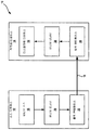
도 1a 는 본 개시물에서 설명하는 양태들에 따른 기법들을 이용할 수도 있는 예시적인 비디오 인코딩 및 디코딩 시스템을 예시하는 블록도이다.
도 1b 는 본 개시물에서 설명하는 양태들에 따른 기법들을 수행할 수도 있는 다른 예시적인 비디오 인코딩 및 디코딩 시스템을 예시하는 블록도이다.
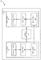
도 2a 는 본 개시물에서 설명하는 양태들에 따른 기법들을 구현할 수도 있는 예시적인 비디오 인코더의 예를 예시하는 블록도이다.
도 2b 는 본 개시물에서 설명하는 양태들에 따른 기법들을 구현할 수도 있는 예시적인 비디오 디코더의 예를 예시하는 블록도이다.
도 3 은 양자화 파라미터 (QP) 조정 값(들) 을 결정하는 예시적인 접근법을 나타낸다.
도 4 는 이미지 내 편평한 영역으로부터 복잡한 영역으로의 예시적인 전이를 예시한다.
도 5 는 편평한-대-복잡한 영역 전이를 검출하는 예시적인 시스템을 나타낸다.
도 6 은 편평한-대-복잡한 영역 검출을 위한 저장 유닛을 예시한다.
도 7 은 본 개시물에서 설명된 양태들에 따른, 이미지에서 복잡한 영역을 검출하는 예시적인 방법을 예시하는 플로우차트이다.1A is a block diagram illustrating an exemplary video encoding and decoding system that may utilize techniques in accordance with aspects described in this disclosure.
1B is a block diagram illustrating another exemplary video encoding and decoding system that may perform techniques in accordance with aspects described in this disclosure.
2A is a block diagram illustrating an example of an exemplary video encoder that may implement techniques in accordance with aspects described in this disclosure.
2B is a block diagram illustrating an example of an exemplary video decoder that may implement techniques in accordance with aspects described in this disclosure.
FIG. 3 shows an exemplary approach for determining the quantization parameter (QP) adjustment value (s).
Figure 4 illustrates an exemplary transition from a flat area to a complex area in an image.
Figure 5 shows an exemplary system for detecting flat-to-complex region transitions.
Figure 6 illustrates a storage unit for flat-versus-complex area detection.
7 is a flow chart illustrating an exemplary method for detecting a complex area in an image, in accordance with aspects described in this disclosure.
일반적으로, 본 개시물은 디스플레이 스트림 압축 (DSC) 과 같은 비디오 압축 기법들을 향상시키는 기법들에 관한 것이다. 좀더 구체적으로, 본 개시물은 코딩될 이미지의 편평한 또는 매끄러운 영역으로부터 복잡한 영역으로의 전이를 검출하는 시스템들 및 방법들에 관한 것이다. 본원에서 설명된 것은 예를 들어, DSC 와 같은 비디오 압축 기법들의 상황에서 비디오 데이터에서 복잡한 영역 검출을 위한 기법들이다. 본 개시물의 양태들은 코딩 동안 레이트 버퍼의 언더플로우 또는 오버플로우가 회피되도록 보장하는 것에 관한 것이다.In general, the present disclosure relates to techniques for improving video compression techniques such as display stream compression (DSC). More particularly, this disclosure relates to systems and methods for detecting transitions from flat or smooth areas of an image to be coded to complex areas. Described herein are techniques for complex area detection in video data in the context of, for example, video compression techniques such as DSC. Aspects of the disclosure relate to ensuring that underflow or overflow of the rate buffer is avoided during coding.
어떤 실시형태들은 본원에서 DSC 표준의 상황에서 설명되지만, 당업자는 본원에서 개시된 시스템들 및 방법들이 임의의 적합한 비디오 코딩 표준에 적용가능할 수도 있음을 알 수 있을 것이다. 예를 들어, 본원에서 개시된 실시형태들은 다음 표준들 중 하나 이상에 적용가능할 수도 있다: 국제 전기통신 연합 (ITU) 전기통신 표준화 부문 (ITU-T) H.261, ISO/IEC (International Organization for Standardization/International Electrotechnical Commission) Moving Picture Experts Group-1 (MPEG 1) Visual, ITU-T H.262 또는 ISO/IEC MPEG-2 Visual, ITU-T H.263, ISO/IEC MPEG 4 Visual, (또한, ISO/IEC MPEG-4 AVC 로서 알려진) ITU-T H.264, 고효율 비디오 코딩 (HEVC), 및 이런 표준들에 대한 임의의 확장판들. 본원에서 설명되는 기법들은 특히 고정 비트 레이트 (CBR) 버퍼 모델을 포함하는 표준들에 적용가능할 수도 있다. 또한, 본 개시물에서 설명하는 기법들은 미래에 개발될 표준들의 일부가 될 수도 있다. 다시 말해서, 본 개시물에서 설명하는 기법들은 이전에 개발된 비디오 코딩 표준들, 현재 개발 중인 비디오 코딩 표준들, 및 차기 비디오 코딩 표준들에 적용가능할 수도 있다.While certain embodiments are described herein in the context of the DSC standard, those skilled in the art will appreciate that the systems and methods disclosed herein may be applicable to any suitable video coding standard. For example, the embodiments disclosed herein may be applicable to one or more of the following standards: ITU Telecommunication Standardization Sector (ITU-T) H.261, International Organization for Standardization (ISO / IEC) / International Electrotechnical Commission Moving Picture Experts Group 1 (MPEG 1) Visual, ITU-T H.262 or ISO / IEC MPEG-2 Visual, ITU-T H.263, ISO / IEC MPEG 4 Visual ITU-T H.264, known as IEC MPEG-4 AVC, High Efficiency Video Coding (HEVC), and any extensions to these standards. The techniques described herein may be particularly applicable to standards that include a fixed bit rate (CBR) buffer model. In addition, the techniques described in this disclosure may be part of future standards to be developed. In other words, the techniques described in this disclosure may be applicable to previously developed video coding standards, currently developing video coding standards, and future video coding standards.
본 개시물의 컨셉들은 실질적으로 시각적으로 무손실 성능을 갖는 여러 유형들의 콘텐츠를 인코딩/디코딩하는 것을 목표로 하는 여러 엘리먼트들 및/또는 모드들을 포함하는 코덱의 부분 (예컨대, DSC) 이거나 또는 그 내에 통합될 수도 있다. 본 개시물은 매끄러운/편평한 영역 (예컨대, 코딩하기에 용이한 영역) 으로부터 복잡한 영역 (예컨대, 코딩하는데 상대적으로 어렵거나 또는 코딩하는데 더 높은 비트수를 필요로 하는 영역) 으로의 전이를 검출하는 복잡한 영역 검출 알고리즘을 제공한다. 이러한 전이가 검출될 때, 코덱에 사용되는 양자화 파라미터 (QP) 는 현재 블록을 코딩하는데 요구되는 예상 레이트를 감소시키기 위해 높은 값으로 증가된다. 이것은 복잡한 영역에서의 시각 정보의 복잡도가 매끄러운/편평한 영역에서 발생할 수 있는 것보다 더욱더 아티팩트들을 마스크할 수도 있기 때문에 바람직하다. 게다가, 코더가 복잡한 블록 상에 (예컨대, 목표 비트레이트를 휠씬 초과하여) 너무 많은 비트들을 소비하는 것을 방지하기 위해서는, 낮은 레이트가 바람직하다.The concepts of the present disclosure may be part of a codec (e.g., a DSC) that includes several elements and / or modes that are intended to encode / decode several types of content that have substantially visually lossless performance, It is possible. This disclosure is based on the discovery that a complex (e.g., relatively difficult to code, or difficult to code) detection of a transition from a smooth / flat area (e.g., And provides an area detection algorithm. When such a transition is detected, the quantization parameter (QP) used in the codec is increased to a high value to reduce the expected rate required to code the current block. This is desirable because the complexity of visual information in complex areas may mask more artifacts than can occur in smooth / flat areas. In addition, a low rate is desirable to prevent the coder from consuming too many bits on a complex block (e.g., far exceeding the target bit rate).
비디오 코딩 표준들Video coding standards
비디오 리코더 또는 컴퓨터에 의해 발생되는 비디오 이미지, TV 이미지, 정지 화상 또는 이미지와 같은, 디지털 이미지는 수평 및 수직 라인들에 배열된 픽셀들 또는 샘플들을 포함할 수도 있다. 단일 이미지에서 픽셀들의 개수는 일반적으로 수 만개이다. 각각의 픽셀은 일반적으로 휘도 및 색차 정보를 포함한다. 압축이 없다면, 이미지 인코더로부터 이미지 디코더로 운반되는 정보의 순수한 양은 실시간 이미지 송신을 실행불가능하게 만들 것이다. 송신될 정보의 양을 감소시키기 위해, JPEG, MPEG 및 H.263 표준들과 같은, 다수의 상이한 압축 방법들이 개발되었다.A digital image, such as a video image, a TV image, a still image or an image generated by a video recorder or a computer, may contain pixels or samples arranged on horizontal and vertical lines. The number of pixels in a single image is typically tens of thousands. Each pixel typically includes luminance and chrominance information. Without compression, the net amount of information conveyed from the image encoder to the image decoder would make real-time image transmission impossible. In order to reduce the amount of information to be transmitted, a number of different compression methods have been developed, such as the JPEG, MPEG and H.263 standards.
비디오 코딩 표준들은 ITU-T H.261, ISO/IEC MPEG-1 Visual, ITU-T H.262 또는 ISO/IEC MPEG-2 Visual, ITU-T H.263, ISO/IEC MPEG-4 Visual 및 (ISO/IEC MPEG-4 AVC 로서 또한 알려진) ITU-T H.264, 및 이런 표준들의 확장판을 포함한 HEVC 를 포함한다.Video coding standards are defined in ITU-T H.261, ISO / IEC MPEG-1 Visual, ITU-T H.262 or ISO / IEC MPEG-2 Visual, ITU-T H.263, ITU-T H.264 (also known as ISO / IEC MPEG-4 AVC), and HEVC including extensions to these standards.
게다가, 비디오 코딩 표준, 즉 DSC 가, VESA 에 의해 개발되었다. DSC 표준은 디스플레이 링크들을 통한 송신을 위해서 비디오를 압축할 수 있는 비디오 압축 표준이다. 디스플레이들의 해상도가 증가함에 따라서, 그에 따라서, 디스플레이들을 구동하는데 요구되는 비디오 데이터의 대역폭이 증가된다. 일부 디스플레이 링크들은 이러한 해상도들에 있어 비디오 데이터의 모두를 디스플레이로 송신하는 대역폭을 갖지 않을 수도 있다. 따라서, DSC 표준은 디스플레이 링크들을 통한 상호 이용가능한, 시각적 무손실 압축을 위한 압축 표준을 규정한다.In addition, a video coding standard, DSC, was developed by VESA. The DSC standard is a video compression standard capable of compressing video for transmission over display links. As the resolution of the displays increases, the bandwidth of the video data required to drive the displays accordingly increases accordingly. Some display links may not have the bandwidth to transmit all of the video data to the display at these resolutions. Thus, the DSC standard defines a compression standard for interoperable, visually lossless compression over display links.
DSC 표준은 H.264 및 HEVC 와 같은, 다른 비디오 코딩 표준들과는 상이하다. DSC 는 인트라-프레임 압축을 포함하지만, 인터-프레임 압축을 포함하지 않는데, 시간 정보가 비디오 데이터를 코딩할 때에 DSC 표준에 의해 사용되지 않을 수도 있다는 것을 의미한다. 이에 반해, 다른 비디오 코딩 표준들은 그들의 비디오 코딩 기법들에서의 인터-프레임 압축을 채용할 수도 있다.The DSC standard differs from other video coding standards, such as H.264 and HEVC. DSC includes intra-frame compression, but does not include inter-frame compression, which means that temporal information may not be used by the DSC standard when coding video data. In contrast, other video coding standards may employ inter-frame compression in their video coding techniques.
비디오 코딩 시스템Video coding system
신규한 시스템들, 장치들, 및 방법들의 여러 양태들이 이하에서 첨부 도면들을 참조하여 좀더 충분히 설명된다. 본 개시물은 그러나, 많은 상이한 형태들로 구현될 수도 있으며, 본 개시물 전반에 걸쳐서 제시되는 임의의 특정의 구조 또는 기능에 한정되는 것으로 해석되어서는 안된다. 대신, 이들 양태들은 본 개시물이 철저하고 완전하게 되도록, 그리고 본 개시물의 범위를 당업자들에게 충분히 전달하기 위해서 제공된다. 본원에서의 교시들에 기초하여, 당업자는 본 개시물의 범위가 본 개시물의 임의의 다른 양태와 독립적으로 구현되든 그와 결합되든, 본원에서 개시된 신규한 시스템들, 장치들, 및 방법들의 임의의 양태를 포괄하도록 의도되는 것으로 이해하여야 한다. 예를 들어, 본원에서 개시된 임의 개수의 양태들을 이용하여, 장치가 구현될 수도 있거나 또는 방법이 실시될 수도 있다. 게다가, 본 개시물의 범위는 본원에서 개시된 본 개시물의 여러 양태들에 추가해서 또는 이 이외에, 다른 구조, 기능, 또는 구조 및 기능을 이용하여 실행되는 그러한 장치 또는 방법을 포괄하도록 의도된다. 본원에서 개시된 임의의 양태는 청구항의 하나 이상의 엘리먼트들에 의해 구현될 수도 있는 것으로 이해되어야 한다.Various aspects of the novel systems, devices, and methods are more fully described below with reference to the accompanying drawings. The present disclosure, however, may be embodied in many different forms and should not be construed as limited to any particular structure or function presented throughout this disclosure. Instead, these aspects are provided so that this disclosure will be thorough and complete, and will fully convey the scope of the disclosure to those skilled in the art. Based on the teachings herein, those skilled in the art will appreciate that any range of novel systems, devices, and methods disclosed herein, whether embodied in or separate from any other aspect of the disclosure, And the like. For example, using any number of aspects disclosed herein, an apparatus may be implemented or a method may be practiced. In addition, the scope of the disclosure is intended to cover such apparatus or methods that are implemented using other structures, functions, or structures and functions in addition to or in addition to the various aspects of the disclosure disclosed herein. It is to be understood that any aspect of the disclosure herein may be embodied by one or more elements of the claims.
특정의 양태들이 본원에서 설명되지만, 이들 양태들의 많은 변형예들 및 치환물들은 본 개시물의 범위 이내 이다. 바람직한 양태들의 일부 이익들 및 이점들이 언급되지만, 본 개시물의 범위는 특유의 이익들, 용도들, 또는 목적들에 한정되는 것으로 의도되지 않는다. 대신, 본 개시물의 양태들은 상이한 무선 기술들, 시스템 구성들, 네트워크들, 및 송신 프로토콜들에 넓게 적용가능한 것으로 의도되며, 이들 중 일부가 일 예로서 도면들에 그리고 바람직한 양태들의 다음 설명에 예시된다. 상세한 설명 및 도면들은 한정하기 보다는 단지 본 개시물의 예시이며, 본 개시물의 범위는 첨부된 청구범위 및 이의 균등물들에 의해 정의된다.While certain aspects are described herein, many variations and permutations of these aspects are within the scope of this disclosure. While certain benefits and advantages of the preferred embodiments are mentioned, the scope of the present disclosure is not intended to be limited to specific advantages, uses, or objects. Instead, aspects of the present disclosure are intended to be broadly applicable to different wireless technologies, system configurations, networks, and transmission protocols, some of which are illustrated by way of example in the drawings and in the following description of preferred aspects . The detailed description and drawings are merely illustrative of the disclosure, rather than limiting, and the scope of the disclosure is defined by the appended claims and their equivalents.
첨부 도면들은 예들을 예시한다. 첨부 도면들에서 참조 번호들로 표시된 엘리먼트들은 다음 설명에서 유사한 참조 번호들로 표시된 엘리먼트들에 대응한다. 본 개시물에서, 서수의 단어들 (예컨대, "제 1", "제 2", "제 3", 및 기타 등등) 로 시작하는 이름들을 갖는 엘리먼트들은 엘리먼트들이 특정의 순서를 갖는다는 것을 반드시 암시하지는 않는다. 대신, 이러한 서수의 단어들은 동일한 또는 유사한 유형의 상이한 엘리먼트들을 지칭하기 위해 단지 사용된다.The accompanying drawings illustrate examples. The elements denoted by reference numerals in the accompanying drawings correspond to elements denoted by like reference numerals in the following description. In the present disclosure, elements having names starting with ordinal words (e.g., "first", "second", "third", and so on) I do not. Instead, the words of such ordinal numbers are only used to refer to different elements of the same or similar type.
도 1a 는 본 개시물에서 설명된 양태들에 따른 기법들을 이용할 수도 있는 예시적인 비디오 코딩 시스템 (10) 을 예시하는 블록도이다. 설명되는 본원에서 사용될 때, 용어 "비디오 코더" 또는 "코더" 는 비디오 인코더들 및 비디오 디코더들 양쪽을 포괄적으로 지칭한다. 본 개시물에서, 용어들 "비디오 코딩" 또는 "코딩" 은 포괄적으로 비디오 인코딩 및 비디오 디코딩을 지칭할 수도 있다. 비디오 인코더들 및 비디오 디코더들에 더해서, 본 출원에서 설명된 양태들은 트랜스코더들 (예컨대, 비트스트림을 디코딩하고 다른 비트스트림을 재-인코딩할 수 있는 디바이스들) 및 미들박스들 (middleboxes) (예컨대, 비트스트림을 수정하고, 변환하고, 및/또는 아니면 조작할 수 있는 디바이스들) 과 같은, 다른 관련된 디바이스들로 확장될 수도 있다.1A is a block diagram illustrating an exemplary
도 1a 에 나타낸 바와 같이, 비디오 코딩 시스템 (10) 은 목적지 디바이스 (14) 에 의해 추후 디코딩될 인코딩된 비디오 데이터를 발생시키는 소스 디바이스 (12) 를 포함한다. 도 1a 의 예에서, 소스 디바이스 (12) 및 목적지 디바이스 (14) 는 별개의 디바이스들을 구성한다. 그러나, 소스 디바이스 (12) 및 목적지 디바이스 (14) 가 도 1b 의 예에 나타낸 바와 같이 동일한 디바이스 상에 또는 부분 상에 있을 수도 있다는 점에 유의한다.As shown in FIG. 1A, the
도 1a 를 다시 참조하면, 소스 디바이스 (12) 및 목적지 디바이스 (14) 는 데스크탑 컴퓨터들, 노트북 (예컨대, 랩탑) 컴퓨터들, 태블릿 컴퓨터들, 셋-탑 박스들, 소위 "스마트" 폰들과 같은 전화기 핸드셋들, 소위 "스마트" 패드들, 텔레비전들, 카메라들, 디스플레이 디바이스들, 디지털 미디어 플레이어들, 비디오 게이밍 콘솔들, 자동차용 컴퓨터들, 비디오 스트리밍 디바이스들, 안경류 및/또는 착용식 컴퓨터와 같은 엔터티에 의해 (에) 착용가능한 (또는, 착탈가능한) 디바이스들 (예컨대, 인간, 동물, 및/또는 다른 피제어 디바이스), 엔터티 내에서 소비되거나, 입수되거나 또는 배치될 수 있는 디바이스들 또는 장치, 및/또는 기타 등등을 포함한, 광범위한 디바이스들 중 임의의 디바이스를 각각 포함할 수도 있다. 여러 실시형태들에서, 소스 디바이스 (12) 및 목적지 디바이스 (14) 는 무선 통신용으로 탑재될 수도 있다.1A, the source device 12 and the destination device 14 may be connected to a telephone such as desktop computers, notebook (e.g., laptop) computers, tablet computers, set-top boxes, Such as computers, handsets, so-called "smart" pads, televisions, cameras, display devices, digital media players, video gaming consoles, automotive computers, video streaming devices, eyewear and / Devices (e.g., human, animal, and / or other controlled devices) that are wearable (or removable) by an entity, devices or devices that may be consumed, ≪ / RTI > and / or the like. In various embodiments, the source device 12 and the destination device 14 may be mounted for wireless communication.
목적지 디바이스 (14) 는 링크 (16) 를 통해서, 디코딩될 인코딩된 비디오 데이터를 수신할 수도 있다. 링크 (16) 는 인코딩된 비디오 데이터를 소스 디바이스 (12) 로부터 목적지 디바이스 (14) 로 이동시킬 수 있는 임의 종류의 매체 또는 디바이스를 포함할 수도 있다. 도 1a 의 예에서, 링크 (16) 는 소스 디바이스 (12) 로 하여금 인코딩된 비디오 데이터를 목적지 디바이스 (14) 로 실시간으로 송신할 수 있게 하는 통신 매체를 포함할 수도 있다. 인코딩된 비디오 데이터는 무선 통신 프로토콜과 같은 통신 표준에 따라서 변조되어 목적지 디바이스 (14) 로 송신될 수도 있다. 통신 매체는 무선 주파수 (RF) 스펙트럼 또는 하나 이상의 물리적인 송신 라인들과 같은, 임의의 무선 또는 유선 통신 매체를 포함할 수도 있다. 통신 매체는 근거리 네트워크, 광역 네트워크, 또는 글로벌 네트워크, 예컨대 인터넷과 같은 패킷-기반 네트워크의 일부를 형성할 수도 있다. 통신 매체는 라우터들, 스위치들, 기지국들, 또는 소스 디바이스 (12) 로부터 목적지 디바이스 (14) 로 통신을 용이하게 하는데 유용할 수도 있는 임의의 다른 장비를 포함할 수도 있다.The destination device 14 may receive the encoded video data to be decoded via the
도 1a 의 예에서, 소스 디바이스 (12) 는 비디오 소스 (18), 비디오 인코더 (20), 및 출력 인터페이스 (22) 를 포함한다. 일부의 경우, 출력 인터페이스 (22) 는 변조기/복조기 (모뎀) 및/또는 송신기를 포함할 수도 있다. 소스 디바이스 (12) 에서, 비디오 소스 (18) 는 비디오 캡쳐 디바이스, 예컨대, 비디오 카메라, 이전에 캡쳐된 비디오를 포함하는 비디오 아카이브, 비디오 콘텐츠 제공자로부터 비디오를 수신하는 비디오 공급 인터페이스, 및/또는 컴퓨터 그래픽스 데이터를 소스 비디오로서 발생시키는 컴퓨터 그래픽스 시스템과 같은 소스, 또는 이런 소스들의 조합을 포함할 수도 있다. 일 예로서, 비디오 소스 (18) 가 비디오 카메라이면, 소스 디바이스 (12) 및 목적지 디바이스 (14) 는 도 1b 의 예에 예시된 바와 같이, 소위 "카메라 폰들" 또는 "비디오 폰들" 을 형성할 수도 있다. 그러나, 본 개시물에서 설명하는 기법들은 비디오 코딩에 일반적으로 적용가능할 수도 있으며, 무선 및/또는 유선 애플리케이션들에 적용될 수도 있다.In the example of FIG. 1A, the source device 12 includes a video source 18, a
캡쳐되거나, 사전-캡쳐되거나, 또는 컴퓨터-발생된 비디오는 비디오 인코더 (20) 에 의해 인코딩될 수도 있다. 인코딩된 비디오 데이터는 소스 디바이스 (12) 의 출력 인터페이스 (22) 를 통해서 목적지 디바이스 (14) 에 송신될 수도 있다. 인코딩된 비디오 데이터는 또한 (또는, 대안적으로) 디코딩 및/또는 플레이백을 위해, 목적지 디바이스 (14) 또는 다른 디바이스들에 의한 추후 액세스를 위해, 저장 디바이스 (31) 상에 저장될 수도 있다. 도 1a 및 도 1b 에 예시된 비디오 인코더 (20) 는 도 2 에 예시된 비디오 인코더 (20), 또는 본원에서 설명되는 임의의 다른 비디오 인코더를 포함할 수도 있다.The captured, pre-captured, or computer-generated video may be encoded by the
도 1a 의 예에서, 목적지 디바이스 (14) 는 입력 인터페이스 (28), 비디오 디코더 (30), 및 디스플레이 디바이스 (32) 를 포함한다. 일부의 경우, 입력 인터페이스 (28) 는 수신기 및/또는 모뎀을 포함할 수도 있다. 목적지 디바이스 (14) 의 입력 인터페이스 (28) 는 링크 (16) 를 통해서 및/또는 저장 디바이스 (31) 로부터, 인코딩된 비디오 데이터를 수신할 수도 있다. 링크 (16) 를 통해서 통신되거나, 또는 저장 디바이스 (31) 상에 제공되는 인코딩된 비디오 데이터는, 비디오 데이터를 디코딩할 때에, 비디오 디코더 (30) 와 같은 비디오 디코더에 의해 사용하기 위한, 비디오 인코더 (20) 에 의해 발생되는 다양한 신택스 엘리먼트들을 포함할 수도 있다. 이런 신택스 엘리먼트들은 통신 매체 상으로 송신되거나, 저장 매체 상에 저장되거나, 또는 파일 서버에 저장된 인코딩된 비디오 데이터와 함께 포함될 수도 있다. 도 1a 및 도 1b 에 예시된 비디오 디코더 (30) 는 도 2b 에 예시된 비디오 디코더 (30), 또는 본원에서 설명되는 임의의 다른 비디오 디코더를 포함할 수도 있다.In the example of FIG. 1A, the destination device 14 includes an
디스플레이 디바이스 (32) 는 목적지 디바이스 (14) 와 통합되거나 이의 외부에 있을 수도 있다. 일부 예들에서, 목적지 디바이스 (14) 는 통합된 디스플레이 디바이스를 포함하며, 또한 외부 디스플레이 디바이스와 인터페이스하도록 구성될 수도 있다. 다른 예들에서, 목적지 디바이스 (14) 는 디스플레이 디바이스일 수도 있다. 일반적으로, 디스플레이 디바이스 (32) 는 디코딩된 비디오 데이터를 사용자에게 디스플레이하고, 액정 디스플레이 (LCD), 플라즈마 디스플레이, 유기 발광 다이오드 (OLED) 디스플레이, 또는 또 다른 유형의 디스플레이 디바이스와 같은 다양한 디스플레이 디바이스들 중 임의의 디바이스를 포함할 수도 있다.The
관련 양태들에서, 도 1b 는 예시적인 비디오 코딩 시스템 (10') 을 나타내며, 여기서, 소스 디바이스 (12) 및 목적지 디바이스 (14) 는 디바이스 (11) 상에 또는 그의 부분에 있다. 디바이스 (11) 는 "스마트" 폰 또는 기타 등등과 같은, 전화기 핸드셋일 수도 있다. 디바이스 (11) 는 소스 디바이스 (12) 및 목적지 디바이스 (14) 와 통신가능하게 동작하는 프로세서/제어기 디바이스 (13) (옵션적으로 존재함) 을 포함할 수도 있다. 도 1b 의 비디오 코딩 시스템 (10'), 및 그의 컴포넌트들은, 다른 점에서는, 도 1a 의 비디오 코딩 시스템 (10), 및 그의 컴포넌트들과 유사하다.1B illustrates an exemplary video coding system 10'wherein the source device 12 and the destination device 14 are on the
비디오 인코더 (20) 및 비디오 디코더 (30) 는 DSC 와 같은, 비디오 압축 표준에 따라서 동작할 수도 있다. 대안적으로, 비디오 인코더 (20) 및 비디오 디코더 (30) 는 다른 독점 또는 산업 표준들, 예컨대, 대안적으로 MPEG4 로서 지칭되는, ITU-T H.264 표준, 파트 10, AVC, HEVC 또는 이런 표준들의 확장판들에 따라서 동작할 수도 있다. 그러나, 본 개시물의 기법들은 임의의 특정의 코딩 표준에 한정되지 않는다. 비디오 압축 표준들의 다른 예들은 MPEG-2 및 ITU-T H.263 을 포함한다.
도 1a 및 도 1b 의 예들에 나타내지는 않았지만, 비디오 인코더 (20) 및 비디오 디코더 (30) 는 오디오 인코더 및 디코더와 각각 통합될 수도 있으며, 오디오 및 비디오 양쪽의 인코딩을 공통 데이터 스트림 또는 별개의 데이터 스트림들로 처리하기 위해 적합한 MUX-DEMUX 유닛들, 또는 다른 하드웨어 및 소프트웨어를 포함할 수도 있다. 적용가능한 경우, 일부 예들에서, MUX-DEMUX 유닛들은 ITU H.223 멀티플렉서 프로토콜, 또는 다른 프로토콜들, 예컨대, 사용자 데이터그램 프로토콜 (UDP) 을 따를 수도 있다.1A and 1B, the
비디오 인코더 (20) 및 비디오 디코더 (30) 각각은 하나 이상의 마이크로프로세서들, 디지털 신호 프로세서들 (DSPs), 주문형 집적회로들 (ASICs), 필드 프로그래밍가능 게이트 어레이들 (FPGAs), 이산 로직, 소프트웨어, 하드웨어, 펌웨어 또는 임의의 이들의 조합들과 같은, 다양한 적합한 인코더 회로 중 임의의 회로로 구현될 수도 있다. 이 기법들이 소프트웨어로 부분적으로 구현되는 경우, 디바이스는 본 개시물의 기법들을 수행하기 위해 소프트웨어용 명령들을 적합한 비일시적 컴퓨터-판독가능 매체에 저장하고, 그 명령들을 하드웨어에서 하나 이상의 프로세서들을 이용하여 실행할 수도 있다. 비디오 인코더 (20) 및 비디오 디코더 (30) 각각은 하나 이상의 인코더들 또는 디코더들에 포함될 수도 있으며, 이들 중 어느 쪽이든 개별 디바이스에서 결합된 인코더/디코더의 부분으로서 통합될 수도 있다.
비디오 코딩 프로세스Video coding process
위에서 간단히 언급한 바와 같이, 비디오 인코더 (20) 는 비디오 데이터를 인코딩한다. 비디오 데이터는 하나 이상의 픽처들을 포함할 수도 있다. 픽처들의 각각은 비디오의 일부를 형성하는 정지 화상이다. 일부의 경우, 픽처는 비디오 "프레임" 으로서 지칭될 수도 있다. 비디오 인코더 (20) 가 비디오 데이터를 인코딩할 때, 비디오 인코더 (20) 는 비트스트림을 발생시킬 수도 있다. 비트스트림은 비디오 데이터의 코딩된 표현을 형성하는 비트들의 시퀀스를 포함할 수도 있다. 비트스트림은 코딩된 픽처들 및 연관된 데이터를 포함할 수도 있다. 코딩된 픽처는 픽처의 코딩된 표현이다.As briefly mentioned above,
비트스트림을 발생하기 위해, 비디오 인코더 (20) 는 비디오 데이터에서의 각각의 픽처에 대해 인코딩 동작들을 수행할 수도 있다. 비디오 인코더 (20) 가 픽처들에 대해 인코딩 동작들을 수행할 때, 비디오 인코더 (20) 는 코딩된 픽처들 및 연관되는 데이터의 시리즈를 발생시킬 수도 있다. 연관되는 데이터는 QP 와 같은 코딩 파라미터들의 세트를 포함할 수도 있다. 코딩된 픽처를 발생시키기 위해, 비디오 인코더 (20) 는 픽처를 동일-사이즈로된 비디오 블록들로 파티셔닝할 수도 있다. 비디오 블록은 샘플들의 2차원 어레이일 수도 있다. 코딩 파라미터들은 모든 비디오 데이터의 블록에 대한 코딩 옵션 (예컨대, 코딩 모드) 을 정의할 수도 있다. 코딩 옵션은 원하는 레이트-왜곡 성능을 달성하기 위해 선택될 수도 있다.To generate the bitstream, the
일부 예들에서, 비디오 인코더 (20) 는 픽처를 복수의 슬라이스들로 파티셔닝할 수도 있다. 슬라이스들의 각각은 이미지 또는 프레임에서의 영역들의 나머지로부터의 정보 없이 독립적으로 디코딩될 수 있는 이미지 (예컨대, 프레임) 에서의 공간적으로 별개의 영역을 포함할 수도 있다. 각각의 이미지 또는 비디오 프레임은 단일 슬라이스로 인코딩될 수도 있거나 또는 각각의 이미지 또는 비디오 프레임은 여러 슬라이스들로 인코딩될 수도 있다. DSC 에서, 각각의 슬라이스를 인코딩하는데 할당된 목표 비트들은 실질적으로 일정할 수도 있다. 픽처에 대해 인코딩 동작을 수행하는 것의 일부분으로서, 비디오 인코더 (20) 는 그 픽처의 각각의 슬라이스에 대해 인코딩 동작들을 수행할 수도 있다. 비디오 인코더 (20) 가 슬라이스에 대해 인코딩 동작을 수행할 때, 비디오 인코더 (20) 는 그 슬라이스와 연관되는 인코딩된 데이터를 발생시킬 수도 있다. 슬라이스와 연관되는 인코딩된 데이터는 "코딩된 슬라이스" 로서 지칭될 수도 있다.In some instances, the
DSC 비디오 인코더DSC video encoder
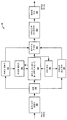
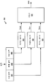
도 2a 는 본 개시물에서 설명하는 양태들에 따른 기법들을 구현할 수도 있는 예시적인 비디오 인코더 (20) 의 예를 예시하는 블록도이다. 비디오 인코더 (20) 는 본 개시물의 기법들 중 일부 또는 모두를 수행하도록 구성될 수도 있다. 일부 예들에서, 본 개시물에서 설명하는 기법들은 비디오 인코더 (20) 의 여러 컴포넌트들 사이에 공유될 수도 있다. 일부 예들에서, 추가적으로 또는 대안적으로, 프로세서 (미도시) 는 본 개시물에서 설명되는 기법들 중 일부 또는 모두를 수행하도록 구성될 수도 있다.2A is a block diagram illustrating an example of an
설명의 목적을 위해, 본 개시물은 DSC 코딩의 상황에서 비디오 인코더 (20) 를 기술한다. 그러나, 본 개시물의 기법들은 다른 코딩 표준들 또는 방법들에 적용가능할 수도 있다.For purposes of explanation, the present disclosure describes a
도 2a 의 예에서, 비디오 인코더 (20) 는 복수의 기능적 컴포넌트들을 포함한다. 비디오 인코더 (20) 의 기능적 컴포넌트들은 칼라-공간 변환기 (105), 버퍼 (110), 편평도 검출기 (115), 레이트 제어기 (120), 예측기, 양자화기, 및 복원기 컴포넌트 (125), 라인 버퍼 (130), 인덱스된 칼라 이력 (135), 엔트로피 인코더 (140), 서브스트림 멀티플렉서 (145), 및 레이트 버퍼 (150) 를 포함한다. 다른 예들에서, 비디오 인코더 (20) 는 더 많거나, 더 적거나, 또는 상이한 기능적 컴포넌트들을 포함할 수도 있다.In the example of FIG. 2A,
칼라-공간 변환기 (105) 는 입력 칼라-공간을 코딩 구현에 사용되는 칼라-공간으로 변환할 수도 있다. 예를 들어, 예시적인 일 실시형태에서, 입력 비디오 데이터의 칼라-공간은 적색, 녹색, 및 청색 (RGB) 칼라-공간이며, 코딩은 휘도 Y, 색차 (chrominance) 녹색 Cg, 및 색차 주황색 Co (YCoCg) 칼라-공간에서 구현된다. 칼라-공간 변환은 비디오 데이터에의 시프트들 및 추가들을 포함한 방법(들) 에 의해 수행될 수도 있다. 다른 칼라-공간들에서의 입력 비디오 데이터가 프로세싱될 수도 있으며 다른 칼라-공간들로의 변환들이 또한 수행될 수도 있다는 점에 유의한다.The color-
관련 양태들에서, 비디오 인코더 (20) 는 버퍼 (110), 라인 버퍼 (130), 및/또는 레이트 버퍼 (150) 를 포함할 수도 있다. 예를 들어, 버퍼 (110) 는 비디오 인코더 (20) 의 다른 부분들에 의한 그의 사용 전에 칼라-공간 변환된 비디오 데이터를 보유할 수도 있다. 다른 예에서, 비디오 데이터는 RGB 칼라-공간에서 저장될 수도 있으며, 칼라-공간 변환된 데이터가 더 많은 비트들을 필요로 할 수도 있기 때문에 필요에 따라서 칼라-공간 변환이 수행될 수도 있다.In related aspects, the
레이트 버퍼 (150) 는 비디오 인코더 (20) 에서 레이트 제어 메커니즘의 부분으로서 기능할 수도 있으며, 레이트 제어기 (120) 와 관련하여 아래에서 더욱더 자세히 설명된다. 각각의 블록 상을 인코딩하는데 소비된 비트들은 블록의 성질에 기초하여 실질적으로 크게 변할 수 있다. 레이트 버퍼 (150) 는 압축된 비디오에서의 레이트 변동들을 평활화할 수 있다. 일부 실시형태들에서, 비트들이 고정 비트 레이트로 버퍼로부터 인출되는 CBR 버퍼 모델이 채용된다. CBR 버퍼 모델에서, 비디오 인코더 (20) 가 너무 많은 비트들을 비트스트림에 추가하면, 레이트 버퍼 (150) 는 오버플로우할 수도 있다. 한편, 비디오 인코더 (20) 는 레이트 버퍼 (150) 의 언더플로우를 방지하기 위해 충분한 비트들을 추가해야 한다.The
비디오 디코더 측 상에서, 비트들이 비디오 디코더 (30) 의 레이트 버퍼 (155) (아래에서 좀더 상세히 설명되는 도 2b 참조) 에 고정 비트 레이트로 추가될 수도 있으며, 비디오 디코더 (30) 가 각각의 블록에 대해 가변 개수의 비트들을 제거할 수도 있다. 적합한 디코딩을 보장하기 위해, 비디오 디코더 (30) 의 레이트 버퍼 (155) 는 압축된 비트 스트림의 디코딩 동안 "언더플로우" 또는 "오버플로우" 하지 않아야 한다.On the video decoder side, bits may be added at a constant bit rate to the rate buffer 155 (see FIG. 2B, described in more detail below) of the
일부 실시형태들에서, 버퍼 충만도 (BF) 는 현재 버퍼에서의 비트수를 나타내는 값들 BufferCurrentSize 및 레이트 버퍼 (150) 의 사이즈, 즉, 임의의 시점에 레이트 버퍼 (150) 에 저장될 수 있는 비트들의 최대 개수를 나타내는 BufferMaxSize 에 기초하여 정의될 수 있다. BF 는 다음과 같이 계산될 수도 있다: In some embodiments, the buffer fullness BF includes values BufferCurrentSize representing the number of bits in the current buffer and the size of the
BF = ((BufferCurrentSize * 100) / BufferMaxSize)BF = ((BufferCurrentSize * 100) / BufferMaxSize)
BF 를 계산하는 상기 접근법이 단지 예시적이며 BF 가 특정의 구현예 또는 상황에 따라서 임의 개수의 상이한 방법들로 계산될 수도 있다는 점에 유의한다.Note that the above approach of calculating BF is merely exemplary and the BF may be computed in any number of different ways depending on the particular implementation or situation.
편평도 검출기 (115) 는 비디오 데이터에서의 복잡한 (즉, 비-편평한) 영역들로부터 비디오 데이터에서의 편평한 (즉, 간단한 또는 균일한) 영역들로의 변화들을 검출할 수 있거나, 및/또는 반대의 경우도 마찬가지이다. 용어들 "복잡한" 및 "편평한" 은 본원에서 일반적으로 비디오 인코더 (20) 가 비디오 데이터의 개개의 영역들을 인코딩하는데 있어서의 난이도를 지칭하기 위해 사용될 것이다. 따라서, 본원에서 사용될 때, 용어 "복잡한" 은, 일반적으로 비디오 인코더 (20) 가 인코딩하기에 복잡한 것과 같은 비디오 데이터의 영역을 기술하며, 예를 들어, 텍스쳐된 비디오 데이터, 높은 공간 주파수, 및/또는 인코딩하기에 복잡한 다른 피쳐들을 포함할 수도 있다. 본원에서 사용될 때 용어 "편평한" 은, 일반적으로 비디오 인코더 (20) 가 인코딩하기에 간단한 것과 같은 비디오 데이터의 영역을 기술하며, 예를 들어, 비디오 데이터에서의 부드러운 그래디언트 (smooth gradient), 낮은 공간 주파수, 및/또는 인코딩하기에 간단한 다른 피쳐들을 포함할 수도 있다. 복잡한 영역으로부터 편평한 영역으로의 전이들이 인코딩된 비디오 데이터에서 양자화 아티팩트들을 감소시키기 위해 비디오 인코더 (20) 에 의해 사용될 수도 있다. 구체적으로 설명하면, 레이트 제어기 (120) 및 예측기, 양자화기, 및 복원기 컴포넌트 (125) 는 복잡한 영역으로부터 편평한 영역으로의 전이들이 식별될 때 이러한 양자화 아티팩트들을 감소시킬 수 있다. 이와 유사하게, 편평한 영역으로부터 복잡한 영역으로의 전이들이 현재 블록을 코딩하는데 요구되는 예상 레이트를 감소시키기 위해 QP 를 증가시키도록 비디오 인코더 (20) 에 의해 사용될 수도 있다.The
레이트 제어기 (120) 는 코딩 파라미터들의 세트, 예컨대, QP 를 결정한다. QP 는 레이트 버퍼 (150) 가 오버플로우 또는 언더플로우하지 않도록 보장하는 목표 비트레이트에 대한 픽처 품질을 최대화하기 위해, 레이트 버퍼 (150) 의 버퍼 충만도 및 비디오 데이터의 이미지 활동도 (예컨대, 복잡한 영역으로부터 편평한 영역으로의 전이 또는 반대의 경우도 마찬가지이다) 에 기초하여 레이트 제어기 (120) 에 의해 조정될 수도 있다. 레이트 제어기 (120) 는 또한 최적의 레이트-왜곡 성능을 달성하기 위해 비디오 데이터의 각각의 블록에 대한 특정의 코딩 옵션 (예컨대, 특정의 모드) 을 선택한다. 레이트 제어기 (120) 는 레이트 제어기가 비트-레이트 제약을 만족하도록, 즉, 전체 실제 코딩 레이트가 목표 비트 레이트 내에 들어 맞도록, 복원된 이미지들의 왜곡을 최소화한다. 따라서, 레이트 제어기 (120) 의 하나의 목적은 레이트에 대한 순간 및 평균 제약들을 만족시키면서도 레이트-왜곡 성능을 최대화하도록 QP(들), 코딩 모드(들), 등과 같은, 코딩 파라미터들의 세트를 결정하는 것이다.
예측기, 양자화기, 및 복원기 컴포넌트 (125) 는 비디오 인코더 (20) 의 적어도 3개의 인코딩 동작들을 수행할 수도 있다. 예측기, 양자화기, 및 복원기 컴포넌트 (125) 는 다수의 상이한 모드들에서 예측을 수행할 수도 있다. 하나의 예시적인 예측 모드는 중간값-적응 예측의 수정된 버전이다. 중간값-적응 예측은 무손실 JPEG 표준 (JPEG-LS) 에 의해 구현될 수도 있다. 예측기, 양자화기, 및 복원기 컴포넌트 (125) 에 의해 수행될 수도 있는 중간값-적응 예측의 수정 버전은 3개의 연속된 샘플 값들의 병렬 예측을 가능하게 할 수도 있다. 다른 예시적인 예측 모드는 블록 예측이다. 블록 예측에서, 샘플들은 라인 상부에 있거나 또는 동일한 라인에서 좌측에 있는 이전에 복원된 픽셀들로부터 예측된다. 일부 실시형태들에서, 비디오 인코더 (20) 및 비디오 디코더 (30) 가 양쪽 다 복원된 픽셀들에 대해 동일한 탐색을 수행하여 블록 예측 사용량들을 결정할 수도 있으며, 따라서, 블록 예측 모드에서 어떤 비트들도 송신될 필요가 없다. 다른 실시형태들에서, 비디오 인코더 (20) 는 비디오 디코더 (30) 가 별개의 탐색을 수행할 필요가 없도록, 탐색을 수행하여 블록 예측 벡터들을 비트스트림으로 시그널링할 수도 있다. 컴포넌트 범위의 중간점을 이용하여 샘플들이 예측되는 중간점 예측 모드가 또한 구현될 수도 있다. 중간점 예측 모드는 심지어 최악의 경우 샘플 (worst-case sample) 에서 압축된 비디오에 대해 요구되는 비트수의 바운딩 (bounding) 을 가능하게 할 수도 있다.The predictor, quantizer, and restorer component 125 may perform at least three encoding operations of the
예측기, 양자화기, 및 복원기 컴포넌트 (125) 는 또한 양자화를 수행한다. 예를 들어, 양자화는 시프터를 이용하여 구현될 수도 있는 2 제곱 (power-of-2) 양자화기를 통해서 수행될 수도 있다. 2 제곱 양자화기 대신 다른 양자화 기법들이 구현될 수도 있다는 점에 유의한다. 예측기, 양자화기, 및 복원기 컴포넌트 (125) 에 의해 수행되는 양자화는 레이트 제어기 (120) 에 의해 결정된 QP 에 기초할 수도 있다. 마지막으로, 예측기, 양자화기, 및 복원기 컴포넌트 (125) 는 또한 역 양자화된 잔차를 예측된 값에 가산하고 그 결과가 샘플 값들의 유효한 범위로부터 벗어나지 않도록 보장하는 것을 포함하는 복원을 수행한다.The predictor, quantizer, and restorer component 125 also perform quantization. For example, the quantization may be performed through a power-of-2 quantizer that may be implemented using a shifter. It should be noted that other quantization techniques may be implemented in place of the 2-squared quantizer. The quantization performed by the predictor, quantizer, and restorer component 125 may be based on the QP determined by the
예측기, 양자화기, 및 복원기 컴포넌트 (125) 에 의해 수행되는 예측, 양자화, 및 복원에 대한 위에서 설명한 예시적인 접근법들은 단지 예시적이며 다른 접근법들이 구현될 수도 있다는 점에 유의한다. 또한, 예측기, 양자화기, 및 복원기 컴포넌트 (125) 가 예측, 양자화, 및/또는 복원을 수행하는 하위 컴포넌트(들) 을 포함할 수도 있다는 점에 유의한다. 또한, 예측, 양자화, 및/또는 복원이 예측기, 양자화기, 및 복원기 컴포넌트 (125) 대신, 여러 별개의 인코더 컴포넌트들에 의해 수행될 수도 있다는 점에 유의한다.It is noted that the exemplary approaches described above for prediction, quantization, and reconstruction performed by the predictor, quantizer, and restorer component 125 are exemplary only and other approaches may be implemented. It should also be noted that the predictor, quantizer, and restorer component 125 may also include a subcomponent (s) that perform prediction, quantization, and / or reconstruction. It should also be noted that prediction, quantization, and / or reconstruction may be performed by several separate encoder components instead of the predictor, quantizer, and reconstructor component 125.
라인 버퍼 (130) 는 예측기, 양자화기, 및 복원기 컴포넌트 (125) 및 인덱스된 칼라 이력 (135) 이 버퍼된 비디오 데이터를 이용할 수 있도록 예측기, 양자화기, 및 복원기 컴포넌트 (125) 로부터의 출력을 유지한다. 인덱스된 칼라 이력 (135) 은 최근에 사용된 픽셀 값들을 저장한다. 최근에 사용된 이들 픽셀 값들은 전용 신택스를 통해서 비디오 인코더 (20) 에 의해 직접 참조될 수 있다.The
엔트로피 인코더 (140) 는 인덱스된 칼라 이력 (135) 및 편평도 검출기 (115) 에 의해 식별된 편평도 전이들에 기초하여, 예측기, 양자화기, 및 복원기 컴포넌트 (125) 로부터 수신된 예측 잔차들 및 임의의 다른 데이터 (예컨대, 예측기, 양자화기, 및 복원기 컴포넌트 (125) 에 의해 식별된 인덱스들) 를 인코딩한다. 일부 예들에서, 엔트로피 인코더 (140) 는 서브스트림 인코더에 대한 클록 당 3개의 샘플들을 인코딩할 수도 있다. 서브스트림 멀티플렉서 (145) 는 무헤더 (headerless) 패킷 멀티플렉싱 방식에 기초하여 비트스트림을 멀티플렉싱할 수도 있다. 이것은 비디오 디코더 (30) 로 하여금 3개의 엔트로피 디코더들을 병렬로 실행가능하게 하여, 클록 당 3개의 픽셀들의 디코딩을 용이하게 한다. 서브스트림 멀티플렉서 (145) 는 패킷들이 비디오 디코더 (30) 에 의해 효율적으로 디코딩될 수 있도록 패킷 순서를 최적화할 수도 있다. 클록 당 2 제곱 픽셀들 (예컨대, 2 픽셀들/클록 또는 4 픽셀들/클록) 의 디코딩을 용이하게 하는, 엔트로피 코딩에 대한 상이한 접근법들이 구현될 수도 있다는 점에 유의한다.The
DSC 비디오 디코더DSC video decoder
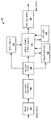
도 2b 는 본 개시물에서 설명하는 양태들에 따른 기법들을 구현할 수도 있는 예시적인 비디오 디코더 (30) 의 예를 예시하는 블록도이다. 비디오 디코더 (30) 는 본 개시물의 기법들 중 일부 또는 모두를 수행하도록 구성될 수도 있다. 일부 예들에서, 본 개시물에서 설명하는 기법들은 비디오 디코더 (30) 의 여러 컴포넌트들 사이에 공유될 수도 있다. 일부 예들에서, 추가적으로 또는 대안적으로, 프로세서 (미도시) 는 본 개시물에서 설명되는 기법들 중 일부 또는 모두를 수행하도록 구성될 수도 있다.2B is a block diagram illustrating an example of an
설명의 목적을 위해, 본 개시물은 DSC 코딩의 상황에서 비디오 디코더 (30) 를 기술한다. 그러나, 본 개시물의 기법들은 다른 코딩 표준들 또는 방법들에도 적용가능할 수도 있다.For purposes of explanation, the present disclosure describes a
도 2b 의 예에서, 비디오 디코더 (30) 는 복수의 기능적 컴포넌트들을 포함한다. 비디오 디코더 (30) 의 기능적 컴포넌트들은 레이트 버퍼 (155), 서브스트림 디멀티플렉서 (160), 엔트로피 디코더 (165), 레이트 제어기 (170), 예측기, 양자화기, 및 복원기 컴포넌트 (175), 인덱스된 칼라 이력 (180), 라인 버퍼 (185), 및 칼라-공간 변환기 (190) 를 포함한다. 비디오 디코더 (30) 의 예시된 컴포넌트들은 도 2a 에서의 비디오 인코더 (20) 와 관련하여 위에서 설명된 대응하는 컴포넌트들과 유사하다. 이와 같이, 비디오 디코더 (30) 의 컴포넌트들의 각각은 위에서 설명한 바와 같은 비디오 인코더 (20) 의 대응하는 컴포넌트들과 유사한 방식으로 동작할 수도 있다.In the example of FIG. 2B,
QP 계산QP calculation
하나의 접근법에서, 현재 블록에 대한 QP (currQP 로 표시됨) 는 다음 방정식에 기초하여 유도되거나 또는 계산될 수도 있다:In one approach, the QP (denoted currQP) for the current block may be derived or calculated based on the following equation:
currQP = prevQ + QpAdj * (diffBits > 0 ? 1: -1),currQP = prevQ + QpAdj * (diffBits> 0? 1: -1),
여기서, prevQP 는 이전 블록과 연관되는 QP 이고, diffBits 는 previousBlockBits 와 targetBits 사이의 차이를 나타내며, QpAdj는 diffBits 의 크기에 기초하여 계산되는 QP 오프셋 값 (예컨대, QP 조정 값) 이며, previousBlockBits 는 이전 블록을 코딩하는데 사용되는 비트수를 나타내며, targetBits 는 현재 블록을 코딩할 목표 비트수를 나타낸다. previousBlockBits > targetBits 일 때, diffBits 는 양이며, 현재 블록 QP 는 오프셋 값 QpAdj 를 prevQP 값에 가산함으로써 유도될 수도 있다. 다시 말해서, QP 값은 diffBits 가 양일 때 prevQP 값으로부터 값이 감소되지 않는다. previousBlockBits ≤ targetBits 일 때, diffBits 는 음수 또는 제로이며, currQP 는 prevQP 값으로부터 증가되지 않는다. 오프셋 값 QpAdj 가 예를 들어, diffBits 에 따라서, diffBits 의 크기가 증가함에 따라서 QpAdj 가 단조 증가하는 방법으로, 계산될 수도 있다는 점에 유의한다.Where prevQP is the QP associated with the previous block, diffBits represents the difference between previousBlockBits and targetBits, QpAdj is the QP offset value (e.g., QP adjustment value) computed based on the size of the diffBits, and previousBlockBits represents the previous block Represents the number of bits used for coding, and targetBits represents the number of target bits to code the current block. previousBlockBits > targetBits, then diffBits is positive and the current block QP may be derived by adding the offset value QpAdj to the prevQP value. In other words, the QP value is not decreased from the prevQP value when diffBits is positive. When previousBlockBits ≤ targetBits, diffBits is negative or zero and currQP is not incremented from the prevQP value. Note that the offset value QpAdj may be calculated, for example, according to diffBits, in such a way that QpAdj increases monotonically as the size of diffBits increases.
QP 조정 값 QpAdj 를 계산하기 위한, 본원에서 디폴트 기법으로서 지칭되는, 하나의 기법이 도 3 을 참조하여 이하 설명될 것이다. 도 3 은 제로에서 시작하는 diffBits 의 값들이 도시되는 축을 포함하는 그래프 (300) 를 제공한다. 디폴트 기법에서, diffBits > 0 일 때, diffBits 는 K 개의 임계값들을 이용하여 K+1 개의 범위들로 분류될 수도 있다. 이들 임계값들은 라벨들 임계치 1, 임계치 2, 임계치 3, …, 및 임계치 K 로 예시되며, 범위들은 라벨들 범위 1, 범위 2, 범위 3, …, 및 범위 K+1 로 예시된다. 도 3 의 디폴트 기법에서는, K 개의 임계값들을 이용하여 diffBits 를 K+1 개의 범위들로 단편화하는 것에 대한 하나의 접근법이 도시된다. 각각의 범위는 특정의 QpAdj 값과 연관될 수도 있으며, 여기서, QpAdj 값은 범위 인덱스가 증가함에 따라서 증가한다. diffBits ≤ 0 일 때, diffBits 의 절대값은 J 개의 임계값들 (미예시) 을 이용하여 J+1 개의 범위들로 분류될 수도 있으며, J+1 개의 범위들의 각각에 대해 할당된 특정의 QpAdj 값이 있을 수도 있다.One technique for calculating the QP adjustment value QpAdj, referred to herein as the default technique, will be described below with reference to FIG. FIG. 3 provides a
다른 양태들에서, currQP 값은 버퍼의 언더플로우 및/또는 오버플로우를 방지하기 위해 (버퍼 충만도 BF 의 관점에서 표현될 수도 있는) 버퍼의 충만도에 기초하여 조정될 수도 있다. 특히, BF 가 어떤 임계치 (예컨대, P1) 를 초과할 때, currQP 는 고정된 오프셋 값 (예컨대, p1) 만큼 증분될 수도 있다. 예를 들어, currQP 는 currQP += p1 에 따라서 조정될 수도 있다. 또, BF 가 어떤 임계치 (예컨대, Q1) 아래로 떨어질 때, currQP 는 q1 만큼 감분될 수도 있다, 예컨대, currQP -= q1. 어떤 양태에서, 복수의 임계치들이 채용될 수도 있으며, 각각의 임계치에 대해 currQP 를 조정하기 위한 대응하는 오프셋 값이 있을 수도 있다.In other aspects, the currQP value may be adjusted based on the fullness of the buffer (which may be expressed in terms of buffer fullness BF) to prevent buffer underflow and / or overflow. In particular, when BF exceeds a certain threshold (e.g., P 1 ), currQP may be incremented by a fixed offset value (e.g., p 1 ). For example, currQP may be adjusted according to currQP + = p 1 . Also, when BF falls below a certain threshold (e.g., Q 1 ), currQP may be decremented by q 1 , e.g., currQP - = q 1 . In some embodiments, multiple thresholds may be employed, and there may be a corresponding offset value for adjusting currQP for each threshold.
복잡한 영역으로부터 편평한 영역으로의 전이가 식별될 때 또는 편평한 영역이 식별될 때, currQP 는 이하에서 더 자세히 설명하는 바와 같이, 낮은 값 (예컨대, 정의된 currQP 값 아래의 값) 으로 설정될 수도 있다.When a transition from a complex region to a flat region is identified or when a flat region is identified, the currQP may be set to a low value (e.g., a value below a defined currQP value), as described in more detail below.
편평한 영역으로부터 복잡한 영역으로의 전이를 검출하기Detecting a transition from a flat area to a complex area
도 4 를 참조하면, 하나 이상의 기법들이 편평한/매끄러운 영역으로부터 복잡한 영역으로의 전이를 검출하는데 이용될 수도 있다. 도 4 는 프레임 또는 예를 들어, 프레임의 슬라이스와 같은 그의 부분일 수도 있는 예시적인 관심 영역 (400) 을 예시한다. 영역 (400) 은 3개의 연속적인 블록들 (405, 410, 및 415) 을 포함할 수도 있다. 이 예에서, 블록 (405) 은 영역 (400) 의 편평한 영역/부분에 대응하며, 블록 (410) 은 영역 (400) 의 전이 영역/부분에 대응하고, 블록 (415) 은 영역 (400) 의 복잡한 영역/부분에 대응한다. 나타낸 바와 같이, 블록 (405) 의 콘텐츠는 편평하거나, 매끄럽거나, 또는 균일하다. 블록 (415) 의 콘텐츠는 텍스처링되어, 전체적으로 균일하지 않은 패턴들을 나타낸다. 블록 (410) 은 균일한 콘텐츠로부터 불균일한 콘텐츠로의 전이를 포함한다. 아래에서 설명하는 바와 같이, 복잡도 계산이 블록들 (405, 410, 및 415) 의 각각에 대해 수행된다.Referring to FIG. 4, one or more techniques may be used to detect a transition from a flat / smooth area to a complex area. 4 illustrates an exemplary region of
본원에서 사용될 때, 편평한 블록은 복잡도 임계치보다 낮은 복잡도 값을 가지는 블록을 지칭할 수도 있다. 블록이 편평한 것으로 결정되는 임계치는 블록을 코딩하는데 요구되는 비트수와 같은 여러 설계 기준들에 기초하여 설정될 수도 있다. 이와 유사하게, 비-편평한 또는 복잡한 블록은 편평하지 않은 블록, 예컨대, 복잡도 임계치보다 크거나 또는 동일한 복잡도 값을 가지는 블록을 지칭할 수도 있다. 블록들의 여러 다른 분류들이 블록들의 연관된 복잡도들에 기초하여 채용될 수도 있으며, 이러한 분류들은 블록들의 복잡도 값들에서의 임계치들에 의해 정의된 범위들일 수도 있다.As used herein, a flat block may refer to a block having a complexity value that is lower than the complexity threshold. The threshold at which the block is determined to be flat may be set based on several design criteria, such as the number of bits required to code the block. Similarly, a non-flat or complex block may refer to a non-flat block, e.g., a block having a complexity value that is greater than or equal to the complexity threshold. Several different classifications of blocks may be employed based on the associated complexities of blocks, and these classifications may be ranges defined by thresholds in the complexity values of the blocks.
용어들 "편평한" 및 "복잡한" 은 또한 블록들 이외의 영역들에에 적용될 수도 있다. 이 경우, 영역들이 블록과 동일한 사이즈가 아닐 수도 있지만, 예컨대, 영역들이 이산적으로 인코딩/디코딩되는 사이즈가 아닐 수도 있지만, 영역들은 또한 영역의 복잡도에 기초하여 편평한 또는 복잡한 것으로 분류될 수도 있다. 예를 들어, 영역은 그 영역 내 각각의 블록이 편평한 블록이면 편평한 영역으로 지칭될 수도 있다. 그러나, 편평한 영역은 그 안에 포함된 블록과 동일한 경계를 갖지 않을 수도 있으며, 영역의 복잡도가 전체 영역에 걸쳐서 계산될 수도 있다. 복잡한 영역들은 유사하게 정의될 수도 있다. 따라서, 영역은 영역에 대한 복잡도 값을 블록들에 대한 복잡도 임계치와는 상이할 수도 있는 복잡도 임계치와 비교함으로써 편평한 또는 복잡한 것으로 분류될 수도 있다. 또, 영역들이 코딩을 위해 블록들로 분할될 수도 있기 때문에, 용어 영역은 본 개시물의 여러 양태들의 이해를 용이하게 하기 위해서 본원에서 개념적으로 사용될 수도 있다.The terms "flat" and "complex" may also be applied to regions other than blocks. In this case, the regions may not be the same size as the block, but the regions may also be classified as flat or complex based on the complexity of the region, although, for example, the regions may not be the size to be discretely encoded / decoded. For example, an area may be referred to as a flat area if each block in the area is a flat block. However, the flat area may not have the same boundaries as the blocks contained therein, and the complexity of the area may be calculated over the entire area. Complex areas may be similarly defined. Thus, an area may be classified as flat or complex by comparing the complexity value for the area with a complexity threshold that may be different from the complexity threshold for the blocks. Also, because regions may be divided into blocks for coding, the term regions may also be conceptually used herein to facilitate understanding of various aspects of the disclosure.
위에서 설명한 바와 같이, 편평한 또는 복잡한 것으로 블록을 분류하기 위해, 블록에 대한 복잡도 값이 결정될 수도 있다. 블록에 대한 복잡도 값은 복잡도 값이 블록을 인코딩하는 난이도를 나타내는 한, 여러 기법들, 예컨대, 가시적인 아티팩트들을 도입함이 없이 블록을 코딩하는데 요구될 수도 있는 비트수에 따라서 결정될 수도 있다.As described above, to classify a block as flat or complex, the complexity value for the block may be determined. The complexity value for a block may be determined according to the number of bits that may be required to code the block without introducing various techniques, e.g., visual artifacts, as long as the complexity value represents the difficulty of encoding the block.
제안된 편평도 검출 기법의 프레임워크가 도 5 의 예시적인 복잡도 검출 시스템 (500) 에 도시된다. 시스템 (500) 은 입력으로서 도 4 의 블록들 (405, 410, 및 415), 또는 이러한 블록들에 관한 정보를 수신한다. 일 구현예에서, 시스템 (500) 은 블록들 (405, 410, 및 415) 의 각각에 대해 복잡도 계산을 수행하여 Ccur, Cnext, 및 Cprev 로 표시되는 블록-당 복잡도 값들을 계산할 수도 있다. 예를 들어, 시스템 (500) 은 블록들 (405, 410, 및 415) 의 각각에 각각 대응하는 복잡도 계산 유닛들 (505, 510, 및 515) 을 포함할 수도 있으며, 복잡도 값들 Cprev, Ccur, 및 Cnext 을, 검출기 (520) 로 각각 출력할 수도 있다. 다른 구현예에서, 3보다 작은 복잡도 값들이 각각의 블록에 대해 계산될 수도 있다. 예를 들어, 인코더는 다음 블록 시간에 대해, 각각 "이전" 및 "현재" 복잡도 값들이 될 주어진 시간 블록에서의 "현재" 및 "다음" 블록 복잡도 값들을 버퍼하거나 또는 저장할 수도 있다. 이러한 방법으로, 단지 "다음" 블록 복잡도 값만이 다음 시간 블록에 대해 계산될 필요가 있을 것이다. 달리 말하면, 인코더는 단지 "다음" 블록 복잡도 값만이 제 2 시간 블록에서 계산되도록, 제 2 블록 시간에서, 각각 "이전" 및 "현재" 복잡도 값들이 될 제 1 시간 블록에서의 "현재" 및 "다음" 블록 복잡도 값들을 버퍼하거나 또는 저장할 수도 있다.The framework of the proposed flatness detection technique is shown in the exemplary
관련 양태들에서, 복잡도 계산 유닛들 (505, 510, 및 515), 및/또는 검출기 (520) 는 별개의 컴포넌트들, 코덱의 동일한 컴포넌트 또는 프로세서의 부분, 또는 하나 이상의 프로세서들에 의해 수행되는 소프트웨어 모듈들일 수도 있다. 시스템 (500) 의 특징들은 하드웨어, 소프트웨어, 펌웨어, 또는 이들의 임의의 조합으로 구현될 수도 있다. 추가적인 관련 양태들에서, 시스템 (500) 은 이미지 또는 관심 영역에 대한 임의 개수의 연속적인 블록들 (예컨대, 슬라이스에서의 4개의 연속적인 블록들) 에 관한 또는 관련한 정보를 수신할 수도 있으며, 연속적인 블록들의 각각에 대해 복잡도 계산들을 수행할 수도 있다.In related aspects, the
일 양태에서, 블록의 복잡도는 블록에서의 픽셀들의 주파수 변환 (예컨대, 이산 코사인 변환 (DCT), Hadamard 변환, 등) 을 취함으로써 계산될 수도 있다. 주파수 변환은 복잡도 값을 발생시키도록 합산될 수도 있는 다수의 주파수 계수들을 초래할 수도 있다. 다른 양태에서, 직류 (DC 또는 제로-주파수) 계수 및/또는 하나 이상의 낮은 주파수 계수들은 총합에 포함되지 않을 수도 있다. 주파수 변환 전에 칼라 변환을 적용하는 것과 같은, 복잡도 값을 결정하는 여러 다른 기법들이 또한 구현될 수도 있다.In an aspect, the complexity of the block may be computed by taking the frequency transform (e.g., discrete cosine transform (DCT), Hadamard transform, etc.) of the pixels in the block. Frequency translation may result in multiple frequency coefficients that may be summed to produce a complexity value. In other aspects, the direct current (DC or zero-frequency) coefficients and / or one or more low frequency coefficients may not be included in the sum. Several other techniques for determining complexity values, such as applying color transformations before frequency conversion, may also be implemented.
관련 양태들에서, 변환 계수들의 절대값 또는 절대 제곱 값은 블록에 대한 복잡도 값을 계산하기 위해 합산될 수도 있다. 추가적인 관련 양태들에서, 루마 채널이 복잡도 값을 계산하기 위해 사용될 수도 있거나, 또는 루마/크로마 채널들 양쪽이 복잡도 값을 계산하기 위해 사용될 수도 있다.In related aspects, the absolute value or absolute value of the transform coefficients may be summed to calculate the complexity value for the block. In additional related aspects, a luma channel may be used to calculate the complexity value, or both luma / chroma channels may be used to calculate the complexity value.
또한 추가적인 관련 양태들에서, 변환 계수들의 서브세트는 절대 합 또는 절대 제곱 합을 계산하는 동안 고려될 수도 있다, 즉, 블록에서의 모든 변환 계수들보다 적은 것이 일부 예시적인 접근법들에서 고려될 수도 있다.Also in additional related aspects, a subset of the transform coefficients may be considered during calculating the absolute sum or absolute sum, i.e., less than all transform coefficients in the block may be considered in some exemplary approaches .
또한 추가적인 양태들에서, 각각의 변환 계수는 가중치로 곱해질 수도 있으며, 각각의 계수에 적용되는 가중치는 변하거나 또는 일정할 수도 있다. 그 후, 가중된 계수들의 절대값 또는 절대 제곱 값이 계산될 수도 있다.Also in additional aspects, each transform coefficient may be multiplied by a weight, and the weights applied to each coefficient may be varied or constant. The absolute value or absolute value of the weighted coefficients may then be calculated.
도 5 의 예를 다시 참조하면, 검출기 (500) 는 Cprev, Ccur, 및 Cnext 에 기초하여, 블록들 (405, 410, 및 415) 이 편평한 영역으로부터 복잡한 영역으로의 전이를 포함하는지 여부를 결정할 수도 있다. 예를 들어, 검출기 (500) 의 출력은 편평한-대-복잡한 영역 전이가 아니라는 것을 표시하는 0, 그리고 편평한-대-복잡한 영역 전이이라는 것을 표시하는 1 과 같은 2진 결과일 수도 있다.Referring back to the example of FIG. 5, the
편평한 영역으로부터 복잡한 영역으로의 전이인지 여부의 결정은 관심 영역 (예컨대, 영역 (400)) 에서의 연속적인 블록들 (예컨대, 블록들 405, 410, 및 415) 의 복잡도 값들에 기초하여 하나 이상의 조건들을 체크함으로써 수행될 수도 있다. 일 실시형태에서, 편평한-대-복잡한 영역 전이인지 여부의 결정이 다음 조건 1 및 조건 2 를 체크하는 것을 통해서 수행된다.The determination of whether a transition from a flat area to a complex area is a transition may be made based on the complexity values of the consecutive blocks (e.g., blocks 405, 410, and 415) in the area of interest (e.g., area 400) Lt; / RTI > In one embodiment, the determination of whether it is a flat-to-complex region transition is performed through checking the following conditions 1 and 2:
조건 1: (Cprev<T0) && (Cnext>T1)Condition 1: (C prev <T 0 ) && (C next > T 1 )
조건 1 에 관하여, 임계치들 T0 및 T1 은 코덱의 파라미터들에 기초하여 조정될 수도 있다. 바람직하게는, 순서 T0<T1 을 따라야 한다. 관련 양태들에서, 편평한 영역으로부터 복잡한 영역으로의 전이이라는 것을 검출하는 것은, 이전 블록 (405) 이 편평한 영역에 대응한다는 것을 표시하는, (i) 이전 블록 (405) 에 대한 복잡도 값이 제 1 임계치 (예컨대, T0) 보다 작다 (또는, 작거나 또는 동일하다) 고, 그리고, 다음 블록 (415) 이 복잡한 영역에 대응한다는 것을 표시하는, (ii) 다음 블록 (415) 에 대한 복잡도 값이 제 2 임계치 (예컨대, T1) 보다 크다 (또는, 크거나 또는 동일하다) 고 결정하는 것을 포함할 수도 있다. 여기서, 이전 블록이 편평한 영역에 대응하고 다음 블록 (415) 이 복잡한 영역에 대응한다는 표시들은, 현재 블록 (410) 에 편평한 영역으로부터 복잡한 영역으로의 전이가 존재한다, 즉, 현재 블록 (410) 이 전이 블록이라는 것을 추가로 표시한다.With respect to condition 1, the thresholds T 0 and T 1 may be adjusted based on the parameters of the codec. Preferably, the sequence T 0 < T 1 should be followed. Detecting that the
조건 2: C0=거짓,C1=거짓Condition 2: C 0 = false, C 1 = false
조건 2 에 관하여, 조건 2 에서의 값들 C0 및 C1 은 본질적으로 불린이며, 도 6 에 나타낸 바와 같이, 편평한-대-복잡한 영역 검출의 이전 이력을 나타낸다. 예를 들어, 이전 블록 시간들에 대한 값들 C0 및 C1 뿐만 아니라, 현재 블록 시간에 대한 C2 가 메모리 저장 유닛 (600) 에 저장될 수도 있다. 일 양태에서, 각각의 블록 시간에서, 복잡도 값들은 1 만큼 좌측으로 시프트된다. 다른 양태에서, 편평한-대-복잡한 영역 검출의 이전 이력 - 즉, 이전 블록 시간들에 대한 값들 C0 및 C1 - 이 상기 조건 2 를 체크하는데 사용된다. 여전히, 다른 양태에서, 조건 1 의 부분들 양쪽이 만족되면, 도 6 에서의 값 C2 는 참으로 설정될 것이다. 편평한-대-복잡한 영역 전이가 검출되더라도, 사용되는 QP 는 현재/다음 블록을 코딩하는데 요구되는 예상 레이트를 감소시키기 위해 전이 블록 또는 전이 블록 이후의 다음 블록에서 (이전 편평한 블록에 비해) 증가될 수도 있다. 그러나, 전이 블록이 부분적으로 편평한 정보 및 부분적으로 복잡한 정보 양쪽을 포함하기 때문에, 전이 블록에서의 QP 값이 (예컨대, 정의된 QP 값을 초과하여) 너무 높지 않을 수 있다는 점에 유의한다. 예를 들어, 전이 블록에 대한 QP 값이 정의된 QP 값을 초과할 때, 아티팩트들이 전이 블록으로부터 복원된 이미지 내에서 현저할 수도 있는 블록의 편평한 부분에서 발생될 수도 있다.With respect to Condition 2, the values C 0 and C 1 in Condition 2 are essentially Boolean and represent the previous history of flat-to-complex region detection, as shown in FIG. For example, C 2 for the current block time as well as values C 0 and C 1 for previous block times may be stored in the
이와 같이, 전이 블록 이후까지 QP 를 증가시키는 것을 지연시키는 것이 바람직할 수도 있다. 예를 들어, QP 는 검출된 전이 블록에 바로 뒤따르는 블록에 대해 (예컨대, 블록 (410) 을 뒤따르는 블록 (415) 에 대해) 증가될 수도 있다. QP 가 첫번째 전체적으로 복잡한 블록 (예컨대, 블록 (415)) 에 대해 높으면, 복잡도는 아티팩트들의 존재를 마스크할 수도 있다.As such, it may be desirable to delay the QP increase until after the transition block. For example, the QP may be incremented (e.g., for
따라서, QP 가 현재 블록에 대해 조정되어야 하는지 여부의 다음 결정은 C1 의 불린 값에 의존한다. C1 이 참이면, 현재 블록에 대한 QP 는 높은 값으로 증가되어야 한다.Thus, the next determination of whether or not the QP should be adjusted for the current block depends on the Boolean value of C 1 . If C 1 is true, the QP for the current block should be increased to a higher value.
인코더 측에서, 각각의 새로운 블록을 프로세싱하는 초기에, 검출 결과들의 이력이 업데이트된다. 즉, C1→C0,C2→C1,C2=거짓. 이것은 현재 블록에 대한 검출 결과를 계산하기 전에 이루어진다. 본질적으로, 이것은 편평한-대-복잡한 전이를 검출하는 것과 QP 를 조정하는 것 사이에 하나의 블록의 오프셋을 추가한다. 위에서 설명한 바와 같이, 이것은 QP 가 전이 블록에 대해 낮은 값으로 유지하도록 보장한다. 게다가, 이것은 로우 (row) 에서의 다수의 블록들이 편평한-대-복잡한 전이들로서 검출되지 않을 수 있도록 보장한다.On the encoder side, at the beginning of processing each new block, the history of detection results is updated. That is, C 1 ? C 0 , C 2 ? C 1 , C 2 = False. This is done before calculating the detection result for the current block. Essentially, this adds an offset of one block between detecting a flat-to-complex transition and adjusting the QP. As described above, this ensures that the QP remains at a low value for the transition block. In addition, this ensures that multiple blocks in the row may not be detected as flat-to-complex transitions.
다른 예에서, 조건 1 에서의 비교 연산자들은 상이한 비교 연산자들로 대체될 수도 있다. 예를 들어, Cprev<T0 대신에, Cprev≤T0 가 대신 사용될 수도 있다.In another example, the comparison operators in condition 1 may be replaced by different comparison operators. For example, instead of C prev <T 0 , C prev ≤ T 0 may be used instead.
상기 실시형태의 하나의 이점은 편평한-대-복잡한 영역 전이들의 검출이 인코더로 하여금 복잡한 영역들에 대해 QP 를 증가시키게 할 수 있다는 점이다. 이것은 블록을 코딩하는데 요구되는 예상 레이트, 및 결과가 영역의 복잡도에 의해 마스크될 아티팩트들을 감소시킬 것이다. 또한, 편평한-대-복잡한 전이 검출의 결과가 인코딩된 비트스트림에서 하나의 비트/블록을 이용하여 디코더로 명시적으로 시그널링될 수 있다. 이것은 디코더로 하여금, 인코더에서 행해지는 것과 같이 복잡도 값들을 계산할 필요없이 QP 를 조정가능하게 한다. 더욱이, 편평한-대-복잡한 영역 전이들을 검출하는 본 기법에서 이용되는 복잡도 계산들 및 예견 (look-ahead) 데이터가 또한 복잡한-대-편평한 영역 전이들을 검출함으로써 DSC 또는 기타 등등과 같은 고정된 레이트 코덱에 대해 효율성들을 실현하는데 이용될 수도 있다. 일 실시형태에서, 하나의 비트를 이용하여 편평한-대-복잡한 전이를 시그널링하는 것을 포함할 수도 있는 기법이 제공된다. 관련 양태들에서, "편평한-대-복잡한" 은 함께 그룹화될 수 있는 가능한 편평도 검출들 또는 분류들의 세트 중 하나이다. 예를 들어, 편평도의 4개의 클래스들 (예컨대, 편평한-대-복잡한, 복잡한-대-편평한, 약간 편평한, 및 매우 편평한) 이 존재하면, 그 결과가 2-비트 코드들의 세트 중 하나로 시그널링될 수도 있다.One advantage of this embodiment is that the detection of flat-to-complex region transitions can cause the encoder to increase the QP for complex regions. This will reduce the expected rate required to code the block, and the artifacts whose result will be masked by the complexity of the area. In addition, the result of the flat-to-complex transition detection can be explicitly signaled to the decoder using one bit / block in the encoded bitstream. This allows the decoder to adjust the QP without having to calculate complexity values as done in the encoder. Moreover, the complexity calculations and look-ahead data used in the present technique to detect flat-to-complex region transitions can also be used to detect complex-to-flat region transitions in a fixed rate codec such as DSC or the like May be used to realize efficiencies for the < / RTI > In one embodiment, a technique is provided that may include signaling a flat-to-complex transition using one bit. In related aspects, "flat-versus-complex" is one of a set of possible flatness detections or classifications that can be grouped together. For example, if there are four classes of flatness (e.g., flat-versus-complex, complex-versus-flat, slightly flat, and very flat), the results may be signaled as one of a set of two- have.
일 실시형태에서, 편평한-대-복잡한 전이가 식별될 때, 블록의 QP 값은 미리 정의된 값 (예컨대, 고정된 높은 값) 으로 설정될 수도 있거나 또는 QP 는 미리 정의된 증가분 또는 값 (예컨대, 고정된 조정 값) 만큼 증가될 수도 있다.In one embodiment, when a flat-to-complex transition is identified, the QP value of the block may be set to a predefined value (e.g., a fixed high value), or the QP may be set to a predefined increment or value Fixed adjustment value).
이미지의 복잡한 영역을 검출하는 예시적인 플로우차트들Exemplary flowcharts for detecting complex areas of an image
도 7 을 참조하면, 이미지의 편평한 영역으로부터 복잡한 영역으로의 전이를 검출하는 예시적인 프로시저가 설명된다. 이미지의 슬라이스는 현재 블록, 다음 블록, 및 이전 블록을 포함할 수도 있다.Referring to Figure 7, an exemplary procedure for detecting a transition from a flat area to an image complex area is described. The slice of the image may include the current block, the next block, and the previous block.
도 7 은 본 개시물의 일 실시형태에 따른, 비디오 데이터를 코딩하는 방법 (700) 을 예시하는 플로우차트이다. 도 7 에 예시된 단계들은 비디오 인코더 (예컨대, 도 2a 에서의 비디오 인코더 (20)), 비디오 디코더 (예컨대, 도 2b 에서의 비디오 디코더 (30)), 또는 예를 들어, 편평도 검출기 (115), 레이트 제어기 (120), 예측기, 양자화기, 및 복원기 컴포넌트 (125), 엔트로피 인코더 (140), 및 레이트 버퍼 (150) 와 같은, 그의 컴포넌트(들) 에 의해 수행될 수도 있다. 편의를 위해, 방법 (700) 은 비디오 인코더 (20), 비디오 디코더 (30), 또는 다른 컴포넌트일 수도 있는 비디오 코더 (또한, 코더로서 간단히 지칭됨) 에 의해 수행되는 것으로 설명된다.FIG. 7 is a flow chart illustrating a
코더 또는 그의 컴포넌트(들) 는 버퍼를 포함하는 복수의 프로그래밍가능 계산 유닛들에 의해 공유되는 통합된 전역 메모리를 포함하는 디바이스 상에서 구현될 수도 있으며, 여기서, 버퍼는 선입선출 (FIFO) 버퍼를 포함할 수도 있다. 디바이스는 적어도 하나의 프로세서 또는 프로세서 회로 (예컨대, 중앙 처리 유닛 (CPU)) 및/또는 그래픽 프로세싱 유닛 (GPU) 를 포함할 수도 있는 집적 회로 (IC) 를 더 포함할 수도 있으며, 여기서, GPU 는 하나 이상의 프로그래밍가능 계산 유닛들을 포함할 수도 있다.The coder or its component (s) may be implemented on a device including an integrated global memory shared by a plurality of programmable computation units including a buffer, wherein the buffer includes a first in first out (FIFO) buffer It is possible. The device may further comprise at least one processor or an integrated circuit (IC) which may include a processor circuit (e.g., a central processing unit (CPU)) and / or a graphics processing unit (GPU) Or more programmable calculation units.
방법 (700) 은 블록 (710) 에서 시작한다. 블록 (710) 에서, 코더는 현재 블록에 대한 현재 복잡도 값, 다음 블록에 대한 다음 복잡도 값, 및 이전 블록에 대한 이전 복잡도 값을 계산한다. 블록 (710) 은 코더가 현재, 다음, 및 이전 블록들 중 각각의 블록에 대해, (i) 변환 계수들을 결정하기 위해 변환을 적용하는 것, 및 (ii) 변환 계수들의 정의된 절대 합을 결정하는 것을 포함할 수도 있다. 변환을 적용하는 것은 DCT 및 Hadamard 변환 중 하나를 적용하는 것을 포함할 수도 있다. 정의된 절대 합을 결정하는 것은 변환 계수들의 절대 합 및 절대 제곱 합 중 하나를 결정하는 것을 포함할 수도 있다.The
블록 (720) 에서, 코더는 이전 복잡도 값이 제 1 임계값 미만이고 다음 복잡도 값이 제 2 임계값보다 크다고 검출하며, 여기서, 제 2 임계값은 제 1 임계값보다 크다.At
블록 (730) 에서, 코더는 현재 블록으로의 전이도 이전 블록으로의 전이도 편평한-대-복잡한 영역 전이가 아니라고 결정한다. 여기서, 코더는 현재 블록 시간에서의 현재, 다음, 및 이전 블록들의 복잡도 값들, 및/또는 하나 이상의 이전 블록 시간들에서의 현재, 다음, 및 이전 블록들의 복잡도 값들에 기초하여 블록 (730) 을 수행한다.At
블록 (740) 에서, 코더는 (i) 이전 복잡도 값이 제 1 임계값 미만이고 다음 복잡도 값이 제 2 임계값보다 크다고 검출하는 것, 및 (ii) 현재 블록으로의 전이도 이전 블록으로의 전이도 편평한-대-복잡한 영역 전이가 아니라고 결정하는 것에 응답하여 다음 블록으로 전이할 때 편평한-대-복잡한 영역 전이를 검출한다.At
블록 (750) 에서, 코더는 옵션적으로, 편평한-대-복잡한 영역 전이를 검출하는 것에 응답하여 QP 를 조정하거나, 및/또는 다음 블록으로 전이할 때 편평한-대-복잡한 영역 전이를 검출하는 것에 응답하여 전이의 표시를 코덱의 인코더로부터 디코더로 시그널링할 수도 있다. 방법 (700) 은 블록 (740) 에서 또는 블록 (750) 에서 종료할 수도 있다.At
다른 고려사항들Other considerations
본 개시물의 양태들은 도 2a 에서의 비디오 인코더 (20) 와 같은, 인코더의 관점에서 설명되었다는 점에 유의해야 한다. 그러나, 당업자들은 발생된 비트스트림을, 예를 들어, 도 2b 에서의 비디오 디코더 (30) 에 의해 디코딩하기 위해 위에서 설명된 동작들에 대한 역방향 동작들이 적용될 수도 있음을 명백히 알 수 있을 것이다.It should be noted that aspects of the present disclosure have been described in terms of an encoder, such as the
본원에서 개시된 정보 및 신호들은 다양한 상이한 기술들 및 기법들 중 어느 것을 이용하여서도 표현될 수도 있다. 예를 들어, 상기 설명 전반에 걸쳐서 인용될 수도 있는 데이터, 명령들, 지령들, 정보, 신호들, 비트들, 심볼들 및 칩들은, 전압들, 전류들, 전자기파들, 자기장들 또는 자기 입자들, 광학장들 또는 광학 입자들, 또는 이들의 임의의 조합으로 표현될 수도 있다.The information and signals disclosed herein may be represented using any of a variety of different techniques and techniques. For example, data, instructions, instructions, information, signals, bits, symbols, and chips that may be referenced throughout the above description may refer to voltages, currents, electromagnetic waves, magnetic fields, , Optical fields or optical particles, or any combination thereof.
본원에서 개시된 실시형태들과 관련하여 설명된 여러가지 예시적인 로직 블록들, 및 알고리즘 단계들은 전자적 하드웨어, 컴퓨터 소프트웨어, 또는 양쪽의 조합들로서 구현될 수도 있다. 이러한 하드웨어와 소프트웨어의 상호 교환가능성을 명확히 예시하기 위하여, 여러가지 예시적인 컴포넌트들, 블록들, 및 단계들은 일반적으로 그들의 기능성의 관점에서 위에서 설명되었다. 이런 기능이 하드웨어 또는 소프트웨어로 구현되는지 여부는 특정의 애플리케이션 및 전체 시스템에 부과되는 설계 제한 사항들에 의존한다. 숙련자들은 각각의 특정의 애플리케이션 마다 설명한 기능을 여러가지 방법으로 구현할 수도 있으며, 그러나 이런 구현 결정들은 본 개시물의 범위로부터의 일탈을 초래하는 것으로 해석되어서는 안된다.The various illustrative logical blocks, and algorithm steps described in connection with the embodiments disclosed herein may be implemented as electronic hardware, computer software, or combinations of both. To clearly illustrate this interchangeability of hardware and software, various illustrative components, blocks, and steps have been described above generally in terms of their functionality. Whether such functionality is implemented in hardware or software depends upon design constraints imposed on the particular application and the overall system. Skilled artisans may implement the described functionality in varying ways for each particular application, but such implementation decisions should not be interpreted as causing a departure from the scope of the present disclosure.
본원에서 설명된 기법들은 하드웨어, 소프트웨어, 펌웨어, 또는 이들의 임의의 조합으로 구현될 수도 있다. 이러한 기법들은 범용 컴퓨터들, 무선 통신 디바이스 핸드셋들, 또는 무선 통신 디바이스 핸드셋들, 자동차, 가전제품들, 웨어러블들, 및/또는 다른 디바이스들에서의 애플리케이션들을 포함한 다수의 용도들을 가진 집적 회로 디바이스들과 같은 다양한 디바이스들 중 임의의 디바이스에서 구현될 수도 있다. 디바이스들 또는 컴포넌트들로서 설명하는 임의의 특징들은 통합 로직 디바이스 내에 함께, 또는 별개의 공용가능한 로직 디바이스들로서 별개로 구현될 수도 있다. 소프트웨어로 구현되는 경우, 이 기법들은 실행될 때, 위에서 설명된 방법들 중 하나 이상을 수행하는 명령들을 포함하는 프로그램 코드를 포함하는 컴퓨터-판독가능 데이터 저장 매체에 의해 적어도 부분적으로 실현될 수도 있다. 컴퓨터-판독가능 데이터 저장 매체는 패키징 재료들을 포함할 수도 있는 컴퓨터 프로그램 제품의 일부를 형성할 수도 있다. 컴퓨터-판독가능 매체는 메모리 또는 데이터 저장 매체들, 예컨대, 동기식 동적 랜덤 액세스 메모리 (SDRAM) 과 같은 랜덤 액세스 메모리 (RAM), 판독 전용 메모리 (ROM), 비-휘발성 랜덤 액세스 메모리 (NVRAM), 전기적으로 소거가능한 프로그래밍가능 판독 전용 메모리 (EEPROM), 플래시 메모리, 자기 또는 광학 데이터 저장 매체들 등을 포함할 수도 있다. 기법들은 추가적으로, 또는 대안적으로, 프로그램 코드를 명령들 또는 데이터 구조들의 유형으로 운반하거나 또는 통신하고 그리고 컴퓨터에 의해 액세스되거나, 판독되거나, 및/또는 실행될 수 있는, 전파 신호들 또는 파들과 같은, 컴퓨터-판독가능 통신 매체에 의해 적어도 부분적으로 실현될 수도 있다.The techniques described herein may be implemented in hardware, software, firmware, or any combination thereof. These techniques may be used with general purpose computers, wireless communication device handsets, or integrated circuit devices having multiple uses, including applications in wireless communication device handsets, automobiles, appliances, wearables, and / Or may be implemented in any of a variety of such devices. Any of the features described as devices or components may be implemented separately within the integrated logic device, or separately as separate, commonly available logic devices. When implemented in software, these techniques, when executed, may be realized at least in part by a computer-readable data storage medium comprising program code comprising instructions for performing one or more of the methods described above. The computer-readable data storage medium may form part of a computer program product that may include packaging materials. The computer-readable medium can be a memory or a data storage medium, such as random access memory (RAM) such as synchronous dynamic random access memory (SDRAM), read only memory (ROM), non-volatile random access memory (NVRAM) Programmable read only memory (EEPROM), flash memory, magnetic or optical data storage media, and the like. The techniques may additionally or alternatively be in the form of signals or waves, such as propagation signals or waves, that can carry or communicate program code in the form of instructions or data structures, and which may be accessed, read, and / Or at least partially realized by a computer-readable communication medium.
프로그램 코드는 하나 이상의 디지털 신호 프로세서들 (DSPs), 범용 마이크로프로세서들, 주문형 집적회로들 (ASIC들), 필드 프로그래밍가능 로직 어레이들 (FPGA들), 또는 다른 등가의 집적 또는 이산 로직 회로와 같은, 하나 이상의 프로세서들을 포함할 수도 있는 프로세서에 의해 실행될 수도 있다. 이러한 프로세서는 본 개시물에서 설명하는 기법들 중 임의의 기법들을 수행하도록 구성될 수도 있다. 범용 프로세서는 마이크로프로세서일 수도 있으며; 그러나 대안적으로는, 프로세서는 임의의 종래의 프로세서, 제어기, 마이크로제어기 또는 상태 머신일 수도 있다. 프로세서는 또한 컴퓨팅 디바이스들의 조합, 예컨대, DSP 와 마이크로프로세서의 조합, 복수의 마이크로프로세서들, DSP 코어와 결합된 하나 이상의 마이크로프로세서들, 또는 임의의 다른 이러한 구성으로서 구현될 수도 있다. 따라서, 용어 "프로세서" 는, 본원에서 사용될 때 전술한 구조 중 임의의 구조, 전술한 구조의 임의의 조합, 또는 본원에서 설명하는 기법들의 구현에 적합한 임의의 다른 구조 또는 장치를 지칭할 수도 있다. 게다가, 일부 양태들에서, 본원에서 설명하는 기능은 인코딩 및 디코딩하도록 구성된 전용 소프트웨어 또는 하드웨어 내에 제공되거나, 또는 결합된 비디오 인코더-디코더 (코덱) 에 포함될 수도 있다. 또한, 이 기법들은 하나 이상의 회로들 또는 로직 엘리먼트들로 전적으로 구현될 수 있다.The program code may be embodied in a computer readable medium, such as one or more digital signal processors (DSPs), general purpose microprocessors, application specific integrated circuits (ASICs), field programmable logic arrays (FPGAs), or other equivalent integrated or discrete logic circuits. Or may be executed by a processor that may include one or more processors. Such a processor may be configured to perform any of the techniques described in this disclosure. The general purpose processor may be a microprocessor; However, alternatively, the processor may be any conventional processor, controller, microcontroller, or state machine. A processor may also be implemented as a combination of computing devices, e.g., a combination of a DSP and a microprocessor, a plurality of microprocessors, one or more microprocessors in conjunction with a DSP core, or any other such configuration. Thus, the term "processor" when used herein may refer to any of the structures described above, any combination of the structures described above, or any other structure or device suitable for implementation of the techniques described herein. In addition, in some aspects, the functions described herein may be provided in dedicated software or hardware configured to encode and decode, or may be included in a combined video encoder-decoder (codec). In addition, the techniques may be implemented entirely with one or more circuits or logic elements.
본 개시물의 기법들은 무선 핸드셋, IC 또는 IC들의 세트 (예컨대, 칩 세트) 를 포함한, 매우 다양한 디바이스들 또는 장치들로 구현될 수도 있다. 개시한 기법들을 수행하도록 구성되는 디바이스들의 기능적 양태들을 강조하기 위해서 여러 컴포넌트들, 또는 유닛들이 본 개시물에서 설명되지만, 상이한 하드웨어 유닛들에 의한 실현을 반드시 필요로 하지는 않는다. 대신, 위에서 설명한 바와 같이, 여러 유닛들이 코덱 하드웨어 유닛에 결합되거나 또는 적합한 소프트웨어 및/또는 펌웨어와 함께, 위에서 설명한 바와 같은 하나 이상의 프로세서들을 포함한, 상호작용하는 하드웨어 유닛들의 컬렉션으로 제공될 수도 있다.The techniques of the present disclosure may be implemented in a wide variety of devices or devices, including wireless handset, IC or a set of ICs (e.g., a chip set). Although several components or units are described in this disclosure to emphasize the functional aspects of the devices configured to perform the disclosed techniques, they do not necessarily require realization by different hardware units. Instead, as described above, multiple units may be coupled to a codec hardware unit or provided with a collection of interacting hardware units, including one or more processors as described above, together with suitable software and / or firmware.
상기는 여러 상이한 실시형태들과 관련하여 설명되었지만, 일 실시형태로부터의 특징들 또는 엘리먼트들은 본 개시물의 교시들로부터 일탈함이 없이 다른 실시형태들과 결합될 수도 있다. 그러나, 개개의 실시형태들 사이의 특징들의 조합들은 반드시 이에 한정되지 않는다. 본 개시물의 여러 실시형태들이 설명되었다. 이들 및 다른 실시형태들은 다음 청구항들의 범위 이내이다.Although the foregoing has been described in connection with various different embodiments, features or elements from one embodiment may be combined with other embodiments without departing from the teachings of the disclosure. However, combinations of features between the individual embodiments are not necessarily limited thereto. Several embodiments of the disclosure have been described. These and other embodiments are within the scope of the following claims.
Claims (30)
상기 이미지의 슬라이스는 현재 블록, 다음 블록, 및 이전 블록을 포함하며,
상기 방법은,
상기 현재 블록에 대한 현재 복잡도 값, 상기 다음 블록에 대한 다음 복잡도 값, 및 상기 이전 블록에 대한 이전 복잡도 값을 계산하는 단계;
상기 이전 복잡도 값이 제 1 임계값 미만이고 상기 다음 복잡도 값이 제 2 임계값보다 크다고 검출하는 단계로서, 상기 제 2 임계값은 상기 제 1 임계값보다 큰, 상기 검출하는 단계;
상기 현재 블록으로의 전이도 상기 이전 블록으로의 전이도 편평한-대-복잡한 영역 전이가 아니라고 결정하는 단계; 및
(i) 상기 이전 복잡도 값이 상기 제 1 임계값 미만이고 상기 다음 복잡도 값이 상기 제 2 임계값보다 크다고 검출하는 것, 및 (ii) 상기 현재 블록으로의 전이도 상기 이전 블록으로의 전이도 편평한-대-복잡한 영역 전이가 아니라고 결정하는 것에 응답하여, 상기 다음 블록으로 전이할 때 편평한-대-복잡한 영역 전이를 검출하는 단계를 포함하는, 이미지의 복잡한 영역을 검출하는 방법.A method for detecting a complex region of an image,
Wherein the slice of the image comprises a current block, a next block, and a previous block,
The method comprises:
Calculating a current complexity value for the current block, a next complexity value for the next block, and a previous complexity value for the previous block;
Detecting that the previous complexity value is less than a first threshold value and the next complexity value is greater than a second threshold value, wherein the second threshold value is greater than the first threshold value;
Determining that the transition to the current block is not a transition to the previous block of a flat-to-complex region transition; And
(i) detecting that the previous complexity value is less than the first threshold value and the next complexity value is greater than the second threshold value, and (ii) determining whether the transition to the current block is also flat To-complex region transition when transitioning to the next block, in response to determining that the non-complex-region transition is not an over-complex region transition.
상기 현재 블록에 대한 상기 현재 복잡도 값, 상기 다음 블록에 대한 상기 다음 복잡도 값, 및 상기 이전 블록에 대한 상기 이전 복잡도 값을 계산하는 단계는,
상기 현재, 다음, 및 이전 블록들 중 각각의 블록에 대해, (i) 변환 계수들을 결정하기 위해 변환을 적용하는 단계 및 (ii) 상기 변환 계수들의 정의된 절대 합을 결정하는 단계를 포함하는, 이미지의 복잡한 영역을 검출하는 방법.The method according to claim 1,
Wherein the step of calculating the current complexity value for the current block, the next complexity value for the next block, and the previous complexity value for the previous block,
For each of the current, next, and previous blocks: (i) applying a transform to determine transform coefficients; and (ii) determining a defined absolute sum of the transform coefficients. A method for detecting a complex region of an image.
상기 변환을 적용하는 단계는 이산 코사인 변환 (DCT) 및 Hadamard 변환 중 하나를 적용하는 단계를 포함하는, 이미지의 복잡한 영역을 검출하는 방법.3. The method of claim 2,
Wherein applying the transform comprises applying one of a discrete cosine transform (DCT) and a Hadamard transform.
상기 DCT 변환 및 상기 Hadamard 변환 중 하나를 적용하기 전에 칼라 변환을 상기 현재, 다음, 및 이전 블록들의 각각에 적용하는 단계를 더 포함하는, 이미지의 복잡한 영역을 검출하는 방법.The method of claim 3,
Further comprising applying a color transformation to each of the current, next, and previous blocks before applying one of the DCT transform and the Hadamard transform.
상기 정의된 절대 합을 결정하는 단계는 상기 변환 계수들의 적어도 서브세트의 절대 합 및 절대 제곱 합 중 하나를 결정하는 단계를 포함하는, 이미지의 복잡한 영역을 검출하는 방법.3. The method of claim 2,
Wherein determining the absolute sum defined comprises determining one of an absolute sum and an absolute squared sum of at least a subset of the transform coefficients.
절대 합 및 절대 제곱 합 중 하나를 결정하는 단계는, 상기 변환 계수들의 서브세트의 절대 합 및 절대 제곱 합 중 하나를 계산하는 단계를 포함하며,
상기 서브세트는 직류 (DC) 계수에 속하는 제 1 변환 계수 및 낮은 주파수 계수에 속하는 제 2 변환 계수 중 적어도 하나를 포함하지 않는, 이미지의 복잡한 영역을 검출하는 방법.6. The method of claim 5,
Wherein determining one of an absolute sum and an absolute squared sum comprises calculating one of an absolute sum and an absolute squared sum of the subset of transform coefficients,
Wherein the subset does not include at least one of a first transform coefficient belonging to a direct current (DC) coefficient and a second transform coefficient belonging to a low frequency coefficient.
상기 편평한-대-복잡한 영역 전이를 검출하는 것에 응답하여 양자화 파라미터 (QP) 를 조정하는 단계를 더 포함하는, 이미지의 복잡한 영역을 검출하는 방법.The method according to claim 1,
Further comprising adjusting a quantization parameter (QP) in response to detecting the flat-to-complex region transition.
상기 QP 를 조정하는 단계는, 편평한-대-복잡한 영역 전이를 검출하는 것에 응답하여 QP 조정 값 만큼 상기 QP 를 증가시키는 단계를 포함하는, 이미지의 복잡한 영역을 검출하는 방법.8. The method of claim 7,
Wherein adjusting the QP comprises increasing the QP by a QP adjustment value in response to detecting a flat-to-complex region transition.
상기 현재 블록으로의 전이도 상기 이전 블록으로의 전이도 편평한-대-복잡한 영역 전이가 아니라고 결정하는 단계는, 현재 블록 시간에서의 상기 현재, 다음, 및 이전 블록들의 상기 복잡도 값들에 기초하는, 이미지의 복잡한 영역을 검출하는 방법.The method according to claim 1,
Wherein determining that the transition to the current block is not a transition to the previous block is also a flat-to-complex region transition, the step of determining whether the transition from the current block to the current block is based on the complexity values of the current, The method comprising the steps of:
상기 현재 블록으로의 전이도 상기 이전 블록으로의 전이도 편평한-대-복잡한 영역 전이가 아니라고 결정하는 단계는, 하나 이상의 이전 블록 시간들에서의 상기 현재, 다음, 및 이전 블록들의 상기 복잡도 값들에 기초하는, 이미지의 복잡한 영역을 검출하는 방법.The method according to claim 1,
Wherein determining that the transition to the current block is not a transition to the previous block is a flat-to-complex region transition further comprises: determining based on the complexity values of the current, next, and previous blocks in the one or more previous block times The method comprising the steps of:
상기 다음 블록으로 전이할 때 편평한-대-복잡한 영역 전이를 검출하는 것에 응답하여, 상기 전이의 표시를 코덱의 인코더로부터 디코더로 시그널링하는 단계를 더 포함하는, 이미지의 복잡한 영역을 검출하는 방법.The method according to claim 1,
Further comprising the step of signaling an indication of the transition from an encoder of the codec to a decoder in response to detecting a flat to complex region transition when transitioning to the next block.
고정된 레이트 코덱의 파라미터들에 기초하여 상기 제 1 및 제 2 임계치들 중 적어도 하나를 동조시키는 단계를 더 포함하는, 이미지의 복잡한 영역을 검출하는 방법.The method according to claim 1,
Further comprising tuning at least one of the first and second thresholds based on parameters of the fixed rate codec.
상기 이미지에 관한 비디오 정보를 저장하도록 구성된 메모리로서, 상기 이미지의 슬라이스는 현재 블록, 다음 블록, 및 이전 블록을 포함하는, 상기 메모리; 및
상기 메모리에 커플링된 적어도 하나의 프로세서 회로를 포함하며,
상기 프로세서 회로는,
상기 현재 블록에 대한 현재 복잡도 값, 상기 다음 블록에 대한 다음 복잡도 값, 및 상기 이전 블록에 대한 이전 복잡도 값을 계산하고;
상기 이전 복잡도 값이 제 1 임계값 미만이고 상기 다음 복잡도 값이 제 2 임계값보다 크다고 검출하고, 상기 제 2 임계값은 상기 제 1 임계값보다 크며;
상기 현재 블록으로의 전이도 상기 이전 블록으로의 전이도 편평한-대-복잡한 영역 전이가 아니라고 결정하고; 그리고
(i) 상기 이전 복잡도 값이 상기 제 1 임계값 미만이고 상기 다음 복잡도 값이 상기 제 2 임계값보다 크다고 검출하는 것, 및 (ii) 상기 현재 블록으로의 전이도 상기 이전 블록으로의 전이도 편평한-대-복잡한 영역 전이가 아니라고 결정하는 것에 응답하여, 상기 다음 블록으로 전이할 때 편평한-대-복잡한 영역 전이를 검출하도록 구성되는, 이미지의 복잡한 영역을 검출하는 디바이스.A device for detecting a complex region of an image,
A memory configured to store video information about the image, wherein the slice of the image comprises a current block, a next block, and a previous block; And
At least one processor circuit coupled to the memory,
The processor circuit comprising:
Calculating a current complexity value for the current block, a next complexity value for the next block, and a previous complexity value for the previous block;
The previous complexity value is less than a first threshold value and the next complexity value is greater than a second threshold value, the second threshold value is greater than the first threshold value;
Determine that the transition to the current block is not a transition to the previous block from a flat-to-complex region transition; And
(i) detecting that the previous complexity value is less than the first threshold value and the next complexity value is greater than the second threshold value, and (ii) determining whether the transition to the current block is also flat To-complex region transition when transitioning to the next block, in response to determining that the non-complex-region transition is not-to-complex region transition.
상기 적어도 하나의 프로세서 회로는 또한,
상기 현재 블록에 대한 상기 현재 복잡도 값, 상기 다음 블록에 대한 상기 다음 복잡도 값, 및 상기 이전 블록에 대한 상기 이전 복잡도 값을 계산하는 것이 상기 현재, 다음, 및 이전 블록들 중 각각의 블록에 대해, (i) 변환 계수들을 결정하기 위해 변환을 적용하는 것 및 (ii) 상기 변환 계수들의 정의된 절대 합을 결정하는 것을 포함하도록 구성되는, 이미지의 복잡한 영역을 검출하는 디바이스.14. The method of claim 13,
The at least one processor circuit may further comprise:
Calculating a current complexity value for the current block, the next complexity value for the next block, and the previous complexity value for the previous block, for each of the current, next, and previous blocks, (i) applying a transform to determine transform coefficients, and (ii) determining a defined absolute sum of the transform coefficients.
상기 적어도 하나의 프로세서 회로는 또한,
이산 코사인 변환 (DCT) 및 Hadamard 변환 중 하나를 적용하는 것을 통해서 상기 변환을 적용하도록 구성되는, 이미지의 복잡한 영역을 검출하는 디바이스.15. The method of claim 14,
The at least one processor circuit may further comprise:
A device for detecting a complex region of an image, the device configured to apply the transform through applying one of a discrete cosine transform (DCT) and a Hadamard transform.
상기 적어도 하나의 프로세서 회로는 또한,
상기 DCT 변환 및 상기 Hadamard 변환 중 하나를 적용하기 전에 칼라 변환을 상기 현재, 다음, 및 이전 블록들의 각각에 적용하도록 구성되는, 이미지의 복잡한 영역을 검출하는 디바이스.16. The method of claim 15,
The at least one processor circuit may further comprise:
And applying a color transform to each of the current, next, and previous blocks before applying one of the DCT transform and the Hadamard transform.
상기 적어도 하나의 프로세서 회로는 또한,
상기 변환 계수들의 적어도 서브세트의 절대 합 및 절대 제곱 합 중 하나를 결정하는 것을 통해서 상기 정의된 절대 합을 결정하도록 구성되는, 이미지의 복잡한 영역을 검출하는 디바이스.15. The method of claim 14,
The at least one processor circuit may further comprise:
And to determine the absolute sum defined by determining one of an absolute sum and an absolute squared sum of at least a subset of the transform coefficients.
상기 적어도 하나의 프로세서 회로는 또한,
상기 변환 계수들의 서브세트의 절대 합 및 절대 제곱 합 중 하나를 계산하는 것을 통해서 절대 합 및 절대 제곱 합 중 하나를 결정하도록 구성되며,
상기 서브세트는 직류 (DC) 계수에 속하는 제 1 변환 계수 및 낮은 주파수 계수에 속하는 제 2 변환 계수 중 적어도 하나를 포함하지 않는, 이미지의 복잡한 영역을 검출하는 디바이스.18. The method of claim 17,
The at least one processor circuit may further comprise:
And to determine one of an absolute sum and an absolute square sum through calculating one of an absolute sum and an absolute square sum of the subset of transform coefficients,
Wherein the subset does not include at least one of a first transform coefficient belonging to a direct current (DC) coefficient and a second transform coefficient belonging to a low frequency coefficient.
상기 적어도 하나의 프로세서 회로는 또한,
편평한-대-복잡한 영역 전이를 검출하는 것에 응답하여 양자화 파라미터 (QP) 를 조정하도록 구성되는, 이미지의 복잡한 영역을 검출하는 디바이스.14. The method of claim 13,
The at least one processor circuit may further comprise:
A device for detecting a complex region of an image, the device configured to adjust a quantization parameter (QP) in response to detecting a flat-to-complex region transition.
상기 적어도 하나의 프로세서 회로는 또한,
편평한-대-복잡한 영역 전이를 검출하는 것에 응답하여 QP 조정 값 만큼 상기 QP 를 증가시키는 것을 통해서 상기 QP 를 조정하도록 구성되는, 이미지의 복잡한 영역을 검출하는 디바이스.20. The method of claim 19,
The at least one processor circuit may further comprise:
And adjust the QP by increasing the QP by a QP adjustment value in response to detecting a flat-to-complex region transition.
상기 적어도 하나의 프로세서 회로는 또한,
현재 블록 시간에서의 상기 현재, 다음, 및 이전 블록들의 상기 복잡도 값들에 기초하여 상기 현재 블록으로의 전이도 상기 이전 블록으로의 전이도 편평한-대-복잡한 영역 전이가 아니라고 결정하도록 구성되는, 이미지의 복잡한 영역을 검출하는 디바이스.14. The method of claim 13,
The at least one processor circuit may further comprise:
And determining that the transition to the current block is not a transition to the previous block based on the complexity values of the current, next, and previous blocks in the current block time. A device that detects complex areas.
상기 적어도 하나의 프로세서 회로는 또한,
하나 이상의 이전 블록 시간들에서의 상기 현재, 다음, 및 이전 블록들의 상기 복잡도 값들에 기초하여 상기 현재 블록으로의 전이도 상기 이전 블록으로의 전이도 편평한-대-복잡한 영역 전이가 아니라고 결정하도록 구성되는, 이미지의 복잡한 영역을 검출하는 디바이스.14. The method of claim 13,
The at least one processor circuit may further comprise:
And determining that the transition to the current block based on the complexity values of the current, next, and previous blocks in one or more previous block times is also a transition to the previous block is not a flat-to-complex region transition , A device for detecting a complex area of an image.
상기 이미지의 슬라이스는 현재 블록, 다음 블록, 및 이전 블록을 포함하며,
상기 장치는,
상기 현재 블록에 대한 현재 복잡도 값, 상기 다음 블록에 대한 다음 복잡도 값, 및 상기 이전 블록에 대한 이전 복잡도 값을 계산하는 수단;
상기 이전 복잡도 값이 제 1 임계값 미만이고 상기 다음 복잡도 값이 제 2 임계값보다 크다고 검출하는 수단으로서, 상기 제 2 임계값은 상기 제 1 임계값보다 큰, 상기 검출하는 수단;
상기 현재 블록으로의 전이도 상기 이전 블록으로의 전이도 편평한-대-복잡한 영역 전이가 아니라고 결정하는 수단; 및
(i) 상기 이전 복잡도 값이 상기 제 1 임계값 미만이고 상기 다음 복잡도 값이 상기 제 2 임계값보다 크다고 검출하는 것, 및 (ii) 상기 현재 블록으로의 전이도 상기 이전 블록으로의 전이도 편평한-대-복잡한 영역 전이가 아니라고 결정하는 것에 응답하여, 상기 다음 블록으로 전이할 때 편평한-대-복잡한 영역 전이를 검출하는 수단을 포함하는, 이미지의 복잡한 영역을 검출하는 장치.An apparatus for detecting a complex region of an image,
Wherein the slice of the image comprises a current block, a next block, and a previous block,
The apparatus comprises:
Means for calculating a current complexity value for the current block, a next complexity value for the next block, and a previous complexity value for the previous block;
Means for detecting that the previous complexity value is less than a first threshold value and the next complexity value is greater than a second threshold value, the second threshold value being greater than the first threshold value;
Means for determining that the transition to the current block is not a transition to the previous block is a flat-to-complex region transition; And
(i) detecting that the previous complexity value is less than the first threshold value and the next complexity value is greater than the second threshold value, and (ii) determining whether the transition to the current block is also flat Means for detecting a flat-to-complex region transition when transitioning to the next block, in response to determining that the region-to-complex region transition is not-to-complex region transition.
상기 현재 블록에 대한 상기 현재 복잡도 값, 상기 다음 블록에 대한 상기 다음 복잡도 값, 및 상기 이전 블록에 대한 상기 이전 복잡도 값을 계산하는 수단은,
변환 계수들을 결정하기 위해 변환을 적용하는 수단, 및 상기 현재, 다음, 및 이전 블록들 중 각각의 블록에 대해 상기 변환 계수들의 정의된 절대 합을 결정하는 수단을 포함하는, 이미지의 복잡한 영역을 검출하는 장치.24. The method of claim 23,
Wherein the means for calculating the current complexity value for the current block, the next complexity value for the next block, and the previous complexity value for the previous block,
Means for applying a transform to determine transform coefficients, and means for determining a defined absolute sum of the transform coefficients for each of the current, next, and previous blocks .
상기 변환을 적용하는 수단은,
이산 코사인 변환 (DCT) 및 Hadmard 변환 중 하나를 적용하는 수단, 및 칼라 변환을 상기 현재, 다음, 및 이전 블록들의 각각에 적용하는 수단을 포함하는, 이미지의 복잡한 영역을 검출하는 장치.25. The method of claim 24,
Wherein the means for applying the transform comprises:
Means for applying one of a discrete cosine transform (DCT) and a Hadmard transform, and means for applying a color transform to each of the current, next, and previous blocks.
편평한-대-복잡한 영역 전이를 검출하는 것에 응답하여 양자화 파라미터 (QP) 를 조정하는 수단을 더 포함하는, 이미지의 복잡한 영역을 검출하는 장치.24. The method of claim 23,
Further comprising means for adjusting a quantization parameter (QP) in response to detecting a flat-to-complex region transition.
상기 이미지의 슬라이스는 현재 블록, 다음 블록, 및 이전 블록을 포함하며,
상기 저장 매체는, 실행될 때, 디바이스의 프로세서로 하여금,
상기 현재 블록에 대한 현재 복잡도 값, 상기 다음 블록에 대한 다음 복잡도 값, 및 상기 이전 블록에 대한 이전 복잡도 값을 계산하게 하고;
상기 이전 복잡도 값이 제 1 임계값 미만이고 상기 다음 복잡도 값이 제 2 임계값보다 크다고 검출하게 하고, 상기 제 2 임계값은 상기 제 1 임계값보다 크고;
상기 현재 블록으로의 전이도 상기 이전 블록으로의 전이도 편평한-대-복잡한 영역 전이가 아니라고 결정하게 하고; 그리고
(i) 상기 이전 복잡도 값이 상기 제 1 임계값 미만이고 상기 다음 복잡도 값이 상기 제 2 임계값보다 크다고 검출하는 것, 및 (ii) 상기 현재 블록으로의 전이도 상기 이전 블록으로의 전이도 편평한-대-복잡한 영역 전이가 아니라고 결정하는 것에 응답하여, 상기 다음 블록으로 전이할 때 편평한-대-복잡한 영역 전이를 검출하게 하는 명령들을 추가로 저장하고 있는, 비일시적 컴퓨터 판독가능 저장 매체.A non-transitory computer readable storage medium storing video information relating to an image,
Wherein the slice of the image comprises a current block, a next block, and a previous block,
The storage medium, when executed, causes the processor of the device,
Calculate a current complexity value for the current block, a next complexity value for the next block, and a previous complexity value for the previous block;
The first complexity value is less than a first threshold value and the next complexity value is greater than a second threshold value, the second threshold value is greater than the first threshold value;
Determine that the transition to the current block is not a transition to the previous block is a flat-to-complex region transition; And
(i) detecting that the previous complexity value is less than the first threshold value and the next complexity value is greater than the second threshold value, and (ii) determining whether the transition to the current block is also flat To-complex region transition when transitioning to the next block, in response to determining that the non-complex region transition is not an over-complex region transition.
실행될 때, 상기 프로세서로 하여금, 상기 현재, 다음, 및 이전 블록들 중 각각의 블록에 대해, 변환 계수들을 결정하기 위해 변환을 적용하는 것 및 상기 변환 계수들의 정의된 절대 합을 결정하는 것을 통해서, 상기 현재 블록에 대한 상기 현재 복잡도 값, 상기 다음 블록에 대한 상기 다음 복잡도 값, 및 상기 이전 블록에 대한 상기 이전 복잡도 값을 계산하게 하는 명령들을 추가로 저장하는, 비일시적 컴퓨터 판독가능 저장 매체.28. The method of claim 27,
When executed, cause the processor to, for each of the current, next, and previous blocks, apply a transform to determine transform coefficients and determine a defined absolute sum of the transform coefficients, Wherein the instructions further cause the computer to calculate the current complexity value for the current block, the next complexity value for the next block, and the previous complexity value for the previous block.
실행될 때, 상기 프로세서로 하여금, 이산 코사인 변환 (DCT) 및 Hadmard 변환 중 하나를 적용하는 것, 및 칼라 변환을 상기 현재, 다음, 및 이전 블록들의 각각에 적용하는 것을 통해서, 상기 변환을 적용하게 하는 명령들을 추가로 저장하는, 비일시적 컴퓨터 판독가능 저장 매체.29. The method of claim 28,
When executed, causes the processor to apply the transform through applying one of a discrete cosine transform (DCT) and a Hadmard transform, and applying a color transform to each of the current, next, and previous blocks ≪ / RTI > wherein the instructions further store instructions.
실행될 때, 상기 프로세서로 하여금, 편평한-대-복잡한 영역 전이를 검출하는 것에 응답하여 양자화 파라미터 (QP) 를 조정하게 하는 명령들을 추가로 저장하는, 비일시적 컴퓨터 판독가능 저장 매체.28. The method of claim 27,
Further comprising instructions that, when executed, cause the processor to adjust the quantization parameter (QP) in response to detecting a flat-to-complex region transition.
Applications Claiming Priority (5)
| Application Number | Priority Date | Filing Date | Title |
|---|---|---|---|
| US201562146913P | 2015-04-13 | 2015-04-13 | |
| US62/146,913 | 2015-04-13 | ||
| US15/078,797 US9936203B2 (en) | 2015-04-13 | 2016-03-23 | Complex region detection for display stream compression |
| US15/078,797 | 2016-03-23 | ||
| PCT/US2016/024016 WO2016167936A1 (en) | 2015-04-13 | 2016-03-24 | Complex region detection for display stream compression |
Publications (1)
| Publication Number | Publication Date |
|---|---|
| KR20170136526A true KR20170136526A (en) | 2017-12-11 |
Family
ID=57112429
Family Applications (1)
| Application Number | Title | Priority Date | Filing Date |
|---|---|---|---|
| KR1020177028261A KR20170136526A (en) | 2015-04-13 | 2016-03-24 | Complex region detection for display stream compression |
Country Status (7)
| Country | Link |
|---|---|
| US (1) | US9936203B2 (en) |
| EP (1) | EP3284256A1 (en) |
| JP (1) | JP2018515016A (en) |
| KR (1) | KR20170136526A (en) |
| CN (1) | CN107431812B (en) |
| TW (1) | TWI634778B (en) |
| WO (1) | WO2016167936A1 (en) |
Families Citing this family (8)
| Publication number | Priority date | Publication date | Assignee | Title |
|---|---|---|---|---|
| TWI538480B (en) * | 2014-05-27 | 2016-06-11 | 敦泰電子股份有限公司 | Image compression system for dynamically adjusting compression parameters by content sensitive detection in video signal |
| US10284849B2 (en) | 2015-04-13 | 2019-05-07 | Qualcomm Incorporated | Quantization parameter (QP) calculation for display stream compression (DSC) based on complexity measure |
| US10244255B2 (en) | 2015-04-13 | 2019-03-26 | Qualcomm Incorporated | Rate-constrained fallback mode for display stream compression |
| US10356428B2 (en) | 2015-04-13 | 2019-07-16 | Qualcomm Incorporated | Quantization parameter (QP) update classification for display stream compression (DSC) |
| JP6537396B2 (en) * | 2015-08-03 | 2019-07-03 | キヤノン株式会社 | IMAGE PROCESSING APPARATUS, IMAGING APPARATUS, AND IMAGE PROCESSING METHOD |
| US10368073B2 (en) * | 2015-12-07 | 2019-07-30 | Qualcomm Incorporated | Multi-region search range for block prediction mode for display stream compression (DSC) |
| US10542267B2 (en) * | 2016-01-21 | 2020-01-21 | Samsung Display Co., Ltd. | Classification preserving image transform compression |
| US11575896B2 (en) * | 2019-12-16 | 2023-02-07 | Panasonic Intellectual Property Corporation Of America | Encoder, decoder, encoding method, and decoding method |
Family Cites Families (39)
| Publication number | Priority date | Publication date | Assignee | Title |
|---|---|---|---|---|
| JP2507215B2 (en) * | 1991-09-02 | 1996-06-12 | 松下電器産業株式会社 | Image coding device |
| JP3152765B2 (en) * | 1991-10-31 | 2001-04-03 | 株式会社東芝 | Image coding device |
| JPH06245199A (en) | 1993-02-19 | 1994-09-02 | Sharp Corp | Picture encoding device |
| US5933451A (en) * | 1994-04-22 | 1999-08-03 | Thomson Consumer Electronics, Inc. | Complexity determining apparatus |
| US6160846A (en) | 1995-10-25 | 2000-12-12 | Sarnoff Corporation | Apparatus and method for optimizing the rate control in a coding system |
| US7016413B2 (en) | 1998-03-20 | 2006-03-21 | International Business Machines Corporation | Adaptively encoding a picture of contrasted complexity having normal video and noisy video portions |
| DE10048735A1 (en) * | 2000-09-29 | 2002-04-11 | Bosch Gmbh Robert | Methods for coding and decoding image sequences and devices therefor |
| US20040252758A1 (en) * | 2002-08-14 | 2004-12-16 | Ioannis Katsavounidis | Systems and methods for adaptively filtering discrete cosine transform (DCT) coefficients in a video encoder |
| US8054880B2 (en) | 2004-12-10 | 2011-11-08 | Tut Systems, Inc. | Parallel rate control for digital video encoder with multi-processor architecture and picture-based look-ahead window |
| US8363717B2 (en) * | 2005-05-17 | 2013-01-29 | Canon Kabushiki Kaisha | Image processing apparatus |
| US20060280242A1 (en) | 2005-06-13 | 2006-12-14 | Nokia Corporation | System and method for providing one-pass rate control for encoders |
| US8879857B2 (en) * | 2005-09-27 | 2014-11-04 | Qualcomm Incorporated | Redundant data encoding methods and device |
| US8787445B2 (en) * | 2007-03-15 | 2014-07-22 | Nvidia Corporation | Allocation of available bits to represent different portions of video frames captured in a sequence |
| KR101172430B1 (en) | 2007-08-17 | 2012-08-08 | 삼성전자주식회사 | Method and apparatus for bit rate control |
| JP5427785B2 (en) * | 2007-09-28 | 2014-02-26 | ドルビー ラボラトリーズ ライセンシング コーポレイション | Video compression technique and video transmission technique |
| US8363719B2 (en) * | 2007-10-29 | 2013-01-29 | Canon Kabushiki Kaisha | Encoding apparatus, method of controlling thereof, and computer program |
| JP5111128B2 (en) * | 2008-01-22 | 2012-12-26 | キヤノン株式会社 | Encoding apparatus, encoding apparatus control method, and computer program |
| KR100952340B1 (en) * | 2008-01-24 | 2010-04-09 | 에스케이 텔레콤주식회사 | Method and Apparatus for Determing Encoding Mode by Using Temporal and Spartial Complexity |
| JP5400876B2 (en) * | 2008-06-16 | 2014-01-29 | ドルビー ラボラトリーズ ライセンシング コーポレイション | Rate control model adaptation based on slice dependency for video coding |
| US9479786B2 (en) * | 2008-09-26 | 2016-10-25 | Dolby Laboratories Licensing Corporation | Complexity allocation for video and image coding applications |
| KR20110091000A (en) | 2008-11-07 | 2011-08-10 | 미쓰비시덴키 가부시키가이샤 | Image encoding device and image decoding device |
| US8897365B2 (en) * | 2008-11-19 | 2014-11-25 | Nvidia Corporation | Video rate control processor for a video encoding process |
| WO2010077333A1 (en) * | 2008-12-29 | 2010-07-08 | Thomson Licensing | Method and apparatus for rate control for compression of video frames |
| US9473792B2 (en) * | 2009-11-06 | 2016-10-18 | Texas Instruments Incorporated | Method and system to improve the performance of a video encoder |
| KR101282193B1 (en) * | 2009-11-10 | 2013-07-04 | 한국전자통신연구원 | Method for Rate Control of Video Encoder using Kalman Filter and FIR Filter |
| KR20110060181A (en) | 2009-11-30 | 2011-06-08 | 한국전자통신연구원 | Apparatus and method for lossless/near-lossless image compression |
| CN102870411B (en) * | 2010-01-08 | 2016-09-21 | 诺基亚技术有限公司 | Device, method and computer program for Video processing |
| EP4250732B1 (en) * | 2011-01-07 | 2024-03-20 | Nokia Technologies Oy | Motion prediction in video coding |
| CN108769693B (en) | 2011-06-10 | 2022-07-08 | 拜特移动网络创新有限责任公司 | Macroblock-level adaptive quantization in quality-aware video optimization |
| JP5988577B2 (en) * | 2011-12-28 | 2016-09-07 | キヤノン株式会社 | Image coding apparatus, image coding method, and program |
| BR122020010110B1 (en) | 2012-03-28 | 2021-08-17 | JVC Kenwood Corporation | IMAGE CODING DEVICE |
| CN102724510B (en) * | 2012-06-21 | 2014-05-28 | 中科开元信息技术(北京)有限公司 | Code rate control algorithm based on fullness degree of virtual encoding buffer area |
| US9299166B2 (en) | 2012-12-13 | 2016-03-29 | Qualcomm Incorporated | Image compression method and apparatus for bandwidth saving |
| US9538190B2 (en) * | 2013-04-08 | 2017-01-03 | Qualcomm Incorporated | Intra rate control for video encoding based on sum of absolute transformed difference |
| US9565440B2 (en) * | 2013-06-25 | 2017-02-07 | Vixs Systems Inc. | Quantization parameter adjustment based on sum of variance and estimated picture encoding cost |
| US9661329B2 (en) * | 2014-04-30 | 2017-05-23 | Intel Corporation | Constant quality video coding |
| US10356428B2 (en) | 2015-04-13 | 2019-07-16 | Qualcomm Incorporated | Quantization parameter (QP) update classification for display stream compression (DSC) |
| US10244255B2 (en) | 2015-04-13 | 2019-03-26 | Qualcomm Incorporated | Rate-constrained fallback mode for display stream compression |
| US10284849B2 (en) | 2015-04-13 | 2019-05-07 | Qualcomm Incorporated | Quantization parameter (QP) calculation for display stream compression (DSC) based on complexity measure |
-
2016
- 2016-03-23 US US15/078,797 patent/US9936203B2/en active Active
- 2016-03-24 EP EP16716348.4A patent/EP3284256A1/en not_active Withdrawn
- 2016-03-24 KR KR1020177028261A patent/KR20170136526A/en active IP Right Grant
- 2016-03-24 JP JP2017553264A patent/JP2018515016A/en not_active Ceased
- 2016-03-24 WO PCT/US2016/024016 patent/WO2016167936A1/en unknown
- 2016-03-24 CN CN201680018987.7A patent/CN107431812B/en active Active
- 2016-04-12 TW TW105111396A patent/TWI634778B/en not_active IP Right Cessation
Also Published As
| Publication number | Publication date |
|---|---|
| TW201703524A (en) | 2017-01-16 |
| EP3284256A1 (en) | 2018-02-21 |
| CN107431812B (en) | 2019-11-29 |
| CN107431812A (en) | 2017-12-01 |
| US20160301933A1 (en) | 2016-10-13 |
| WO2016167936A1 (en) | 2016-10-20 |
| JP2018515016A (en) | 2018-06-07 |
| TWI634778B (en) | 2018-09-01 |
| US9936203B2 (en) | 2018-04-03 |
Similar Documents
| Publication | Publication Date | Title |
|---|---|---|
| EP3284253B1 (en) | Rate-constrained fallback mode for display stream compression | |
| US10284849B2 (en) | Quantization parameter (QP) calculation for display stream compression (DSC) based on complexity measure | |
| US9936203B2 (en) | Complex region detection for display stream compression | |
| EP3132602B1 (en) | System and method for selecting quantization parameter (qp) in display stream compression (dsc) | |
| US9930346B2 (en) | System and method for flatness detection for display stream compression (DSC) | |
| EP3132605B1 (en) | System and method for lagrangian parameter calculation for display stream compression (dsc) | |
| US10631005B2 (en) | System and method for coding in block prediction mode for display stream compression (DSC) | |
| US10356428B2 (en) | Quantization parameter (QP) update classification for display stream compression (DSC) | |
| US10123045B2 (en) | Modification to block size for transform mode in display stream compression | |
| WO2015164369A1 (en) | System and method for coding in pattern mode for display stream compression (dsc) |
Legal Events
| Date | Code | Title | Description |
|---|---|---|---|
| A201 | Request for examination | ||
| A302 | Request for accelerated examination | ||
| E902 | Notification of reason for refusal | ||
| E701 | Decision to grant or registration of patent right |