KR20170066563A - Central wing panel for a flying vehicle and method on its control - Google Patents
Central wing panel for a flying vehicle and method on its control Download PDFInfo
- Publication number
- KR20170066563A KR20170066563A KR1020177012129A KR20177012129A KR20170066563A KR 20170066563 A KR20170066563 A KR 20170066563A KR 1020177012129 A KR1020177012129 A KR 1020177012129A KR 20177012129 A KR20177012129 A KR 20177012129A KR 20170066563 A KR20170066563 A KR 20170066563A
- Authority
- KR
- South Korea
- Prior art keywords
- wing
- wings
- central
- frame section
- actuator
- Prior art date
Links
- 238000000034 method Methods 0.000 title claims description 16
- 230000007704 transition Effects 0.000 abstract description 6
- 230000007423 decrease Effects 0.000 abstract 1
- 230000007246 mechanism Effects 0.000 description 17
- 239000000969 carrier Substances 0.000 description 1
- 230000003028 elevating effect Effects 0.000 description 1
- 238000007562 laser obscuration time method Methods 0.000 description 1
- 238000012986 modification Methods 0.000 description 1
- 230000004048 modification Effects 0.000 description 1
- 239000000758 substrate Substances 0.000 description 1
- 230000001360 synchronised effect Effects 0.000 description 1
Images


Classifications
-
- B—PERFORMING OPERATIONS; TRANSPORTING
- B64—AIRCRAFT; AVIATION; COSMONAUTICS
- B64C—AEROPLANES; HELICOPTERS
- B64C3/00—Wings
- B64C3/38—Adjustment of complete wings or parts thereof
- B64C3/56—Folding or collapsing to reduce overall dimensions of aircraft
-
- B—PERFORMING OPERATIONS; TRANSPORTING
- B60—VEHICLES IN GENERAL
- B60F—VEHICLES FOR USE BOTH ON RAIL AND ON ROAD; AMPHIBIOUS OR LIKE VEHICLES; CONVERTIBLE VEHICLES
- B60F5/00—Other convertible vehicles, i.e. vehicles capable of travelling in or on different media
- B60F5/02—Other convertible vehicles, i.e. vehicles capable of travelling in or on different media convertible into aircraft
-
- B—PERFORMING OPERATIONS; TRANSPORTING
- B64—AIRCRAFT; AVIATION; COSMONAUTICS
- B64C—AEROPLANES; HELICOPTERS
- B64C37/00—Convertible aircraft
-
- B—PERFORMING OPERATIONS; TRANSPORTING
- B60—VEHICLES IN GENERAL
- B60Y—INDEXING SCHEME RELATING TO ASPECTS CROSS-CUTTING VEHICLE TECHNOLOGY
- B60Y2200/00—Type of vehicle
- B60Y2200/50—Aeroplanes, Helicopters
- B60Y2200/51—Aeroplanes
-
- Y—GENERAL TAGGING OF NEW TECHNOLOGICAL DEVELOPMENTS; GENERAL TAGGING OF CROSS-SECTIONAL TECHNOLOGIES SPANNING OVER SEVERAL SECTIONS OF THE IPC; TECHNICAL SUBJECTS COVERED BY FORMER USPC CROSS-REFERENCE ART COLLECTIONS [XRACs] AND DIGESTS
- Y02—TECHNOLOGIES OR APPLICATIONS FOR MITIGATION OR ADAPTATION AGAINST CLIMATE CHANGE
- Y02T—CLIMATE CHANGE MITIGATION TECHNOLOGIES RELATED TO TRANSPORTATION
- Y02T50/00—Aeronautics or air transport
- Y02T50/10—Drag reduction
-
- Y02T50/145—
Landscapes
- Engineering & Computer Science (AREA)
- Aviation & Aerospace Engineering (AREA)
- Mechanical Engineering (AREA)
- Transportation (AREA)
- Aerodynamic Tests, Hydrodynamic Tests, Wind Tunnels, And Water Tanks (AREA)
- Toys (AREA)
- Body Structure For Vehicles (AREA)
- Hybrid Electric Vehicles (AREA)
Abstract
지상 운송 및 항공 운송을 위한 하이브리드 운송체를 위한 중앙 날개 패널이 제시된다. 중앙 날개 패널은 하나 이상의 크로스 부재에 의해 연결되는 전방 프레임 섹션 및 후방 프레임 섹션을 갖는다. 중앙 날개 패널은 또한 전방 프레임 섹션의 대향 단부 부근에 위치 설정되는 제1 수직 축선 및 제2 수직 축선을 가질 수 있으며, 공중 모드와 지상 모드 사이에서의 천이를 위해, 제1 날개는 제1 수직 축선을 중심으로 회전하도록 구성되고, 제2 날개는 제2 수직 축선을 중심으로 회전하도록 구성된다. 중앙 날개 패널은 전방 프레임 섹션의 하위 부분을 따라 실질적으로 평행하게 연장되는 제1 수평 축선을 또한 가질 수 있으며, 중앙 날개 패널은, 운송체의 받음각의 조정을 가능하게 하도록 제1 수평 축선을 중심으로 회전하도록 구성된다. 중앙 날개 패널은 후방 프레임 섹션의 하위 부분을 따라 연장되는 제2 수평 축선을 또한 가질 수 있으며, 후방 프레임 섹션은, 공중 모드와 지상 모드 사이에서의 천이를 위해 제1 날개 및 제2 날개로부터의 후방 프레임 섹션의 결합 및 분리를 가능하게 하도록 제2 수평 축선을 중심으로 회전하게 구성된다. 중앙 날개 패널은 날개의 후미 에지를 따라 연장되는 제3 수평 축선을 또한 가질 수 있어, 보조날개 및 플랩의 회전을 허용하며, 이에 따라 보조날개 및 플랩은 날개의 상위 전방 부분 상에 절첩되고, 이에 따라 날개의 깊이가 줄어들게 된다.A central wing panel for a hybrid vehicle for ground transportation and air transportation is presented. The central wing panel has a front frame section and a rear frame section connected by one or more cross members. The central wing panel may also have a first vertical axis and a second vertical axis positioned adjacent opposite ends of the front frame section and for transitioning between the air mode and the ground mode, And the second wing is configured to rotate about a second vertical axis. The central wing panel may also have a first horizontal axis extending substantially parallel along a lower portion of the front frame section, the central wing panel having a first horizontal axis about the first horizontal axis to allow adjustment of the angle of incidence of the carrier Respectively. The central wing panel may also have a second horizontal axis extending along a lower portion of the rear frame section, the rear frame section having a first wing for transition between the air mode and the ground mode, And configured to rotate about a second horizontal axis to enable engagement and disengagement of the frame sections. The central wing panel may also have a third horizontal axis extending along the trailing edge of the wing, allowing rotation of the secondary wing and flap, whereby the secondary wing and flap are folded over the upper anterior portion of the wing, As a result, the depth of the wing decreases.

Description
본 발명은 대체로 비행체(flying vehicle)를 위한 중앙 날개 패널에 관한 것이다. 이러한 중앙 날개 패널의 구체적인 한 가지 용도는, 하이브리드 항공-지상 운송수단(hybrid air and ground transportation vehicle) 상에 날개를 장착하기 위한 것이다.The present invention generally relates to a central wing panel for a flying vehicle. One specific use of such a central wing panel is for mounting the wing on a hybrid air and ground transportation vehicle.
지상 운송을 위한 운송체(예컨대, 자동차) 및 항공 운송을 위한 운송체(예컨대, 비행기)가 오래 동안 존재해 왔다. 보다 최근에는, 다른 범주의 운송 수단, 즉 항공 용도 및 통상적인 지상 용도에 완전히 호환될 수 있는 통합형 하이브리드 차량을 개발하는 것과 관련하여 노력을 기울이고 있다.BACKGROUND ART Transport vehicles (for example, automobiles) for ground transportation and transportation vehicles (for example, airplanes) for air transportation have existed for a long time. More recently, efforts have been made to develop integrated hybrid vehicles that are fully compatible with other categories of vehicles, aviation and conventional terrestrial applications.
이러한 하이브리드 운송체 중 하나는 WO 2007/114877(이하, “WO’877”)에 설명되어 있는 “Terrafugia Transition”이다. WO’877 공보는, 4륜 샤시 및 절첩 가능한 날개를 구비하여, 자동차일 뿐만 아니라 2인용 항공기인 운송체를 개시하고 있다. 지상에서의 엔진의 동력은 전방 차축으로 전달되며, 휠(wheel)은 통상적인 조향 핸들에 의해 조향되는 반면, 공중에서는, 엔진이 운송체 기체(vehicle fuselage)의 후방에 위치 설정되는 프로펠러를 회전시킨다. 이러한 운송체에는 컴팩트한 윙 루트(wing root)가 구비되어 있으며, 이러한 윙 루트는 운송체의 양측에서 운송체 기체에 견고하게 연결되고, 이러한 윙 루트에 대해 제1 힌지 메커니즘을 통해 날개가 연결되어 있다. 제1 힌지 메커니즘은 수직으로 날개를 접는 것을 허용한다. 제1 힌지 메커니즘에 대한 회전 축선은 운송체의 길이방향 축선[즉, 롤(roll)의 축선]에 대해 평행하다. 상기 날개는, 날개 상에서 외부로 중간에 있는 제2 힌지 메커니즘으로서, 하방으로 날개의 외측 절반부를 접을 수 있도록 하는 제2 힌지 메커니즘을 포함한다. 제2 힌지 메커니즘에 대한 회전 축선도 또한 운송체의 길이방향 축선[즉, 롤(roll)의 축선]에 대해 평행하다.One such hybrid vehicle is the " Terrafugia Transition " described in WO 2007/114877 (hereinafter " WO'877 "). WO < RTI ID = 0.0 > 877 < / RTI > discloses a carrier which is a four-wheeled chassis and a foldable wing, The power of the engine on the ground is transmitted to the front axle and the wheel is steered by a conventional steering handle whereas in the air the engine rotates the propeller positioned on the rear of the vehicle fuselage . Such carriers are provided with compact wing roots which are firmly connected to the carrier body on both sides of the carrier and whose wings are connected to these wings via a first hinge mechanism have. The first hinge mechanism allows the wings to be folded vertically. The axis of rotation for the first hinge mechanism is parallel to the longitudinal axis of the carrier (i.e., the axis of the roll). The wing includes a second hinge mechanism for folding the outer half of the wing downwardly as a second hinge mechanism intermediate to the outside on the wing. The axis of rotation for the second hinge mechanism is also parallel to the longitudinal axis of the carrier (i.e., the axis of the roll).
“AeroMobil”은 WO 2013/032409(이하 “WO’409”)에 설명되어 있는 다른 하이브리드 운송체이다. WO’409는 또한 하이브리드 운송체로서, 패널의 양단부에서 2개의 수직 회전 축선에 의해 단일 자유도를 갖는 중앙 날개 패널에 대한 단일 크로스바 구조를 갖는 하이브리드 운송체를 개시하고 있다. 중앙 날개 패널은 상기 회전 축선을 중심으로 한 날개의 후퇴를 가능하게 한다. "AeroMobil" is another hybrid vehicle described in WO 2013/032409 (hereinafter "WO'409"). WO ' 409 also discloses a hybrid vehicle having a single crossbar structure for a central wing panel having a single degree of freedom by two vertical rotation axes at both ends of the panel, as a hybrid vehicle. The central wing panel enables retraction of the wings about the axis of rotation.
“Terrafugia Transition” 및 “Aeromobil” 양자 모두는 날개를 접을 수 있도록 하는 메커니즘을 구비하고 있지만, 이러한 메커니즘 중 어느 것도 날개의 다른 기능, 예컨대 받음각의 조절, 보조날개(aileron)의 조절 등을 제어할 수 없다. 따라서, 종종 운송체의 복잡성, 비용 및 중량을 증가시킬 수 있는 별도의 독립적인 시스템 또는 메커니즘이 요구된다.Although both "Terrafugia Transition" and "Aeromobil" have mechanisms for folding the wings, none of these mechanisms can control other functions of the wing, such as the control of the angle of attack, the adjustment of the ailerons, none. Thus, there is often a need for a separate, independent system or mechanism that can increase the complexity, cost, and weight of the vehicle.
이러한 문제에 대한 해법은, 날개의 장착, 변형(즉, 작동 위치들 사이에서의 이동) 및 받음각의 변경을 위해 구성되는 중앙 날개 패널(즉, 날개 장착 구조)을 제공한다.A solution to this problem provides a central wing panel (i.e., a wing mounting structure) configured for mounting, deforming (i.e., moving between operating positions) and changing the angle of attack of the wing.
제1 양태에 있어서, 비행체를 위한 중앙 날개 패널은 본체 및 이 본체의 각 측면에 위치 설정되는 날개를 포함하며, 상기 중앙 날개 패널은, 본체의 길이방향 축선과 실질적으로 정렬되도록 상기 본체에 연결하기 위한 지지 구조; 이 지지 구조의 전방 부분에 장착되는 전방 횡방향 부재 및 상기 지지 구조의 후방 부분에 장착되는 후방 횡방향 부재로서, 상기 전방 횡방향 부재 및 후방 횡방향 부재는 각각 상기 본체의 길이방향 축선에 대해 수직인 축선으로서 실질적으로 수평인 회전 축선을 갖는 것인 전방 횡방향 부재 및 후방 횡방향 부재; 전방 횡방향 부재에 연결되며 전방 횡방향 부재의 회전 축선을 중심으로 회전 가능한 날개 지지 부재로서, 상기 날개 지지 부재에는 각각의 날개의 전방 부분이 날개 지지 부재에 연결되도록 하는 날개 피봇 커넥터(wing pivot connector)가 마련되며, 각각의 날개는, 날개가 본체로부터 실질적으로 수평으로 연장되는 제1 날개 위치와, 날개가 본체의 길이방향 축선에 대해 평행하게 실질적으로 수평으로 놓이는 제2 날개 위치 사이에서 각각의 커넥터의 실질적인 수직 축선을 중심으로 피봇 가능한 것인 날개 지지 부재; 상기 후방 횡방향 부재에 연결되는 날개 잠금 부재로서, 잠금 위치와 해제 위치 사이에서 후방 횡방향 부재를 중심으로 한 회전에 의해 이동 가능하며, 상기 잠금 위치는, 날개 잠금 부재 상의 잠금 세그먼트(lock segment)가 각각의 날개의 후방 부분에서의 대응하는 잠금 세그먼트와 결합되어 날개가 제1 날개 위치로부터 제2 날개 위치로 이동하는 것을 방지하는 위치이고, 상기 해제 위치는, 상기 잠금 세그먼트가 대응하는 잠금 세그먼트로부터 분리되어 날개가 제1 날개 위치와 제2 날개 위치 사이에서 이동하는 것을 허용하는 것인 위치인 것인 날개 잠금 부재; 제1 날개 위치에 있을 때 날개의 입사각을 조절하기 위해 전방 횡방향 부재의 회전 축선을 중심으로 지지 구조를 피봇시키기 위한 액추에이터를 포함한다.In a first aspect, a central wing panel for a vehicle includes a body and a wing positioned on each side of the body, the central wing panel having at least one of: Support structure for; A front transverse member mounted to a front portion of the support structure and a rear transverse member mounted to a rear portion of the support structure, wherein the front transverse member and the rear transverse member are each perpendicular to the longitudinal axis of the body The front transverse member and the rear transverse member having a substantially horizontal axis of rotation as an axis of rotation; A wing support member connected to the front transverse member and rotatable about a rotation axis of the front transverse member, the wing support member having a wing pivot connector, such that the front portion of each wing is connected to the wing support member, Each wing having a first wing position in which the wings extend substantially horizontally from the body and a second wing position in which the wings are positioned substantially parallel to the longitudinal axis of the body, A wing support member pivotable about a substantially vertical axis of the connector; A wing lock member connected to the rearward transverse member, the wing lock member being movable by rotation about a rear transverse member between a lock position and a release position, the lock position comprising a lock segment on a wing lock member, Is engaged with a corresponding locking segment at the rear portion of each wing to prevent the wing from moving from the first wing position to the second wing position, the release position being such that the locking segment The wing lock member being a position that permits the wing to be moved apart between the first wing position and the second wing position; And an actuator for pivoting the support structure about the axis of rotation of the front transverse member to adjust the angle of incidence of the wing when in the first wing position.
제2 양태에 있어서, 비행체는, 본체 및 이 본체의 각 측면 상에 위치 설정되는 날개를 포함하며, 상기 날개는 상기 제1 양태의 중앙 날개 패널에 의해 상기 본체 상에 장착되고, 지상 운송 및 항공 운송을 위한 하이브리드 운송체는 본체, 선실, 꼬리, 조향 가능한 휠 및 피동 휠을 포함하는 휠의 세트, 엔진, 프로펠러, 및 본체의 각 측면 상에 위치 설정되는 날개를 포함하며, 상기 날개는 제1 양태의 중앙 날개 패널에 의해 본체 상에 장착된다.In a second aspect, a flying body includes a body and a wing positioned on each side of the body, the wing being mounted on the body by a central wing panel of the first aspect, A hybrid vehicle for transportation comprises a body, a cabin, a set of wheels comprising a tail, a steerable wheel and a driven wheel, an engine, a propeller, and a wing positioned on each side of the body, Is mounted on the body by the central wing panel of the embodiment.
제3 양태에서는, 제2 양태의 운송체를 작동하는 방법으로서, 날개는 초기에 제1 날개 위치에 있으며, 상기 방법은, 잠금 위치로부터 해제 위치로 날개 잠금 부재를 회전시키는 단계; 제1 날개 위치와 제2 날개 위치 사이에서 각각의 날개 피봇 커넥터를 중심으로 각각의 날개를 회전시키는 단계; 날개가 제1 날개 위치와 제2 날개 위치 사이에서 이동할 때 지지 구조를 틸팅(tilting)시키도록 액추에이터를 작동시키는 단계를 포함하는 것인 방법이 제시된다.In a third aspect, a method of operating the carrier of the second aspect, wherein the vane is initially in a first vane position, the method comprising: rotating the vane lock member from a locked position to a released position; Rotating each wing about a respective wing pivot connector between a first wing position and a second wing position; And actuating the actuator to tilting the support structure as the wing moves between the first wing position and the second wing position.
제4 양태에서는, 제2 양태의 운송체를 작동시키는 방법으로서, 날개가 초기에 제2 날개 위치에 있으며, 상기 방법은, 제2 날개 위치와 제1 날개 위치 사이에서 각각의 날개 피봇 커넥터를 중심으로 각각의 날개를 회전시키는 단계; 날개가 제2 날개 위치와 제1 날개 위치 사이에서 이동할 때 지지 구조를 틸팅시키도록 액추에이터를 작동시키는 단계; 해제 위치로부터 잠금 위치로 날개 잠금 부재를 회전시키는 단계를 포함하는 것인 방법이 제시된다.In a fourth aspect, there is provided a method of operating the carrier of the second aspect, wherein the wing is initially in a second wing position, the method further comprising positioning each wing pivot connector between a second wing position and a first wing position, Rotating each wing with a wing; Actuating the actuator to tilt the support structure as the wing moves between the second wing position and the first wing position; And rotating the blade locking member from the unlocked position to the locked position.
첨부 도면은 중앙 날개 패널 및 작동 방법의 실시예를 제시하고 있다.
도 1은 공중 작동을 위해 구성된 하이브리드 운송체의 일 실시예의 측면 사시도이다.
도 2는 지상 작동을 위해 구성된 하이브리드 운송체의 측면 사시도이다.
도 3은 중앙 날개 패널의 일 실시예의 일부를 도시하는, 공중 작동을 위해 구성된 하이브리드 운송체의 측면도이다.
도 4는 중앙 날개 패널의 일 실시예의 일부이다.
도 5는 중앙 날개 패널의 일 실시예의 일부이다.
도 6은 중앙 날개 패널의 일 실시예의 일부이다.
도 7은 중앙 날개 패널의 일 실시예의 일부이다.
도 8은 중앙 날개 패널의 일 실시예의 일부이다.The accompanying drawings illustrate embodiments of a central wing panel and method of operation.
1 is a side perspective view of one embodiment of a hybrid vehicle constructed for aerial operation.
Figure 2 is a side perspective view of a hybrid vehicle configured for ground operation.
Figure 3 is a side view of a hybrid vehicle configured for aerial operation, showing a portion of an embodiment of a central wing panel.
Figure 4 is a portion of one embodiment of a central wing panel.
Figure 5 is a portion of one embodiment of a central wing panel.
Figure 6 is part of an embodiment of a central wing panel.
Figure 7 is part of an embodiment of a central wing panel.
Figure 8 is a portion of one embodiment of a central wing panel.
이제 첨부 도면에 제시된 비한정적인 예시적 실시예를 상세히 참조한다. 가능하면 언제든지, 동일한 또는 유사한 부분을 지칭하기 위해 도면 전체에 걸쳐 동일한 도면부호가 사용될 수 있다.Reference will now be made in detail to the non-limiting exemplary embodiments presented in the accompanying drawings. Wherever possible, the same reference numerals may be used throughout the drawings to refer to the same or like parts.
발명의 Invention 실시예에In the embodiment 대한 예 Example for
도 1 및 도 2는, 각각 공중 작동(air operation) 및 지상 작동(ground operation)을 위해 구성된 예시적인 일 실시예에 따른 하이브리드 운송체(100)를 도시한 것이다. 운송체(100)는, 적어도 비행, 육상이동(taxiing), 이륙 및 착륙 중에 공중 작동을 위해 구성된다. 상기 운송체(100)의 구성은 지상에 있는 동안 공중 작동으로부터 지상 작동으로 또는 반대로 변형될 수 있다. 운송체(100)는, 지상에서 이동하는 동안, 예컨대 도로를 따라 운전하는 동안 지상 작동을 위해 구성된다.Figures 1 and 2 illustrate a
운송체(100)는 본체(110), 선실(120), 접어넣을 수 있는 날개(130)의 세트[제1 날개(301) 및 제2 날개(302)], 꼬리(140), 프로펠러(150) 그리고 전륜(161) 및 후륜(162)의 세트를 포함할 수 있는 휠(wheel)을 포함한다. 운송체(100)는 또한 샤시, 그리고 (공중 작동 중에) 프로펠러(150)를 구동하도록 또는 (지상 작동 중에) 전륜(161) 혹은 후륜(162)을 구동하도록 구성되어 본체(110) 내에 수용되는 엔진(170)을 갖는다.The
도 1 및 도 2에 도시된 바와 같이, 접어넣을 수 있는 날개(130)는 각각의 날개(130) 상의 보조날개(131)를 포함한다. 각각의 보조날개(131)는 힌지에 의해 각각의 날개(130)의 후미 에지(tailing edge)에 부착된다. 보조날개(131)는, 비행 중에 통상의 방식으로 운송체의 길이방향 축선을 중심으로 한 운송체(100)의 롤(roll)을 제어하기 위해 사용된다. 꼬리(140)는 꼬리(140)의 각 측면에 승강부(141)를 포함한다. 승강부(141)는 힌지에 의해 각각의 꼬리 섹션(110)의 후미 에지에 부착된다. 승강부(141)는, 비행 중에, 통상의 방식으로 운송체(100)의 피치(pitch)를 제어하기 위해 사용된다.As shown in FIGS. 1 and 2, the
운송체(100)는 도 3 내지 도 8에 도시된 바와 같이 중앙 날개 패널(300)을 더 포함한다. 도 3 내지 도 8에서는, 각각의 도면에서 다른 구성요소의 보다 양호한 예시를 가능하게 하도록 단지 제1 날개(301) 또는 제2 날개(302)만이 도시되어 있다. 각각의 도면에 양 날개 모두가 도시되어 있지는 않지만, 본원에서 설명되는 바와 같은 도시된 날개에 관한 모든 양태는 도시되지 않은 다른 날개에도 역시 적용된다는 것을 이해할 것이다.The
중앙 날개 패널(300)은 예를 들어 도 3에 도시된 바와 같이 운송체의 길이방향 축선과 실질적으로 정렬되도록 운송체(100)의 본체(110) 내에 위치 설정된다. 중앙 날개 패널(300)은, 본체(110) 내에 수용될 수 있는, 운송체(100)의 구조 프레임(도시되어 있지 않음) 및 날개(130)에 결합된다. 중앙 날개 패널(300)은 다수의 축을 중심으로 한 날개(130)의 조정을 허용하도록 구성될 수 있다.The
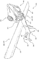
도 4는 중앙 날개 패널(300)의 예시적인 실시예를 도시한 것이다. 중앙 날개 패널(300)은 전방 횡방향 부재 및 날개 지지 부재를 포함하는 전방 프레임 섹션(310) 그리고 후방 횡방향 부재 및 날개 잠금 부재를 포함하는 후방 프레임 섹션(320)을 갖는데, 전방 프레임 섹션과 후방 프레임 섹션은 하나 이상의 크로스 부재(330)에 의해 연결된다. 도 4 내지 도 6에 도시된 바와 같이, 전방 프레임 섹션(310) 및 후방 프레임 섹션(320)은, 상호 연결된 복수 개의 수직 부재, 수평 부재 및 대각 부재를 갖는다.FIG. 4 illustrates an exemplary embodiment of a
도 4에 도시된 바와 같이, 전방 프레임 섹션(310)은 날개 피봇 커넥터(wing pivot connector)에 의해 제1 날개(301) 및 제2 날개(302)(도 4에는 도시되어 있지 않음)의 전방 부분에 회전 가능하게 결합된다. 전방 프레임 섹션(310)은, 수직으로 배향되며 대향 단부에 위치 설정되는 한 쌍의 힌지 메커니즘(311 및 312)을 갖는다. 제1 수직 축선(321) 및 제2 수직 축선(322)은 힌지 메커니즘(311) 및 힌지 메커니즘(312)에 의해 형성된다. 제1 날개(301) 및 제2 날개(302)는 제1 수직 축선(321) 및 제2 수직 축선(322)을 중심으로 회전하도록 구성된다. 전방 프레임 섹션(310)은, 도 4에 도시된 바와 같이, 제1 날개(301) 및 제2 날개(302)의 전방 부분을 향해 연장되는 정지부(323 및 324)를 포함한다. 정지부(323 및 324)는, 전방 방향으로(즉, 연장 위치에서) 평행을 넘는 제1 날개(301) 및 제2 날개(302)의 회전을 억제하도록 구성된다. 제1 수직 축선(321) 및 제2 수직 축선(322)을 중심으로 한 제1 날개(301) 및 제2 날개(302)의 회전은, 운송체(100)에 대한 공중 작동 모드(도 1 참고)와 지상 작동 모드(도 2 참고) 사이의 천이 쌍이다.4, the
제1 날개(301) 및 제2 날개(302)는 하나 이상의 액추에이터 메커니즘에 의해 제1 수직 축선(321) 및 제2 수직 축선(322)을 중심으로 회전하도록 구성된다. 예를 들면, 중앙 날개 패널(300)은, 도 4에 도시된 바와 같이, 전방 프레임 섹션(310)에 연결되며 제1 날개(301)에 링크(link)된 제1 액추에이터(341)를 포함한다. 제1 액추에이터(341)은, 제1 수직 축선(321)을 중심으로 한 제1 날개(301)의 회전을 유발하도록 연장 또는 수축하게 되도록 구성된다. 중앙 날개 패널(300)은, 제2 수직 축선(322)을 중심으로 한 제2 날개(302)의 회전을 유발하도록 구성되어 제2 날개(302)(도시되어 있지 않음)에 링크되고 전방 프레임 섹션(310)에 연결되는 제2 액추에이터(도시되어 있지 않음)를 포함한다.The
전방 프레임 섹션(310)은 운송체(100)의 구조 프레임에 회전 가능하게 결합된다. 예를 들면, 전방 프레임 섹션(310)의 전방 횡방향 부재(313)를 형성하는 하위 부재는, 운송체(100)의 구조 프레임에 결합되어, 상기 전방 횡방향 부재(313)에 대해 실질적으로 평행한 제1 수평 축선(314)이 형성될 수 있도록 할 수 있다. 중앙 날개 패널(300)은 도 4에 도시된 바와 같이 제1 수평 축선(314)을 중심으로 회전하도록 구성된다.The
중앙 날개 패널(300)은 하나 이상의 액추에이터 메커니즘에 의해 제1 수평 축선(314)을 중심으로 회전한다. 예를 들면, 중앙 날개 패널(300)은, 일 단부에서 중앙 날개 패널(300)에 결합되고 운송체(100)의 구조 프레임(도시되어 있지 않음)에 결합되는 제3 액추에이터(343)를 포함할 수 있다. 도 4에 도시된 바와 같이, 제3 액추에이터(343)는 후방 프레임 섹션(320)의 하위 부분에 결합된다. 다른 실시예에서는, 제1 수평 축선(314)을 중심으로 한 중앙 날개 패널(300)의 회전을 구동하기 위해 추가적인 액추에이터가 사용될 수 있다는 것이 고려된다. The
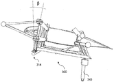
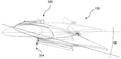
도 5는, 제1 날개(301)가 실질적으로 수평 방향이 되게 하도록 적어도 부분적으로 연장되는 제3 액추에이터(343)를 도시한 것이다. 도 6에 있어서, 제3 액추에이터(343)는 중앙 날개 패널(300)이 제1 수평 축선(314)을 중심으로 각도(β)만큼 회전하게 하면서 후퇴하게 된다. 각도(β)는 예컨대 약 0 내지 15 도일 수 있다. 도 7은 제3 액추에이터(343)(도시되어 있지 않음)에 의해 제1 수평 축선(314)을 중심으로 한 중앙 날개 패널(300)의 회전을 도시한 것이며, 이러한 회전은 수평에 대해 각도(α)만큼 날개의 입사(incidence)의 조절을 가능하게 한다. 각도(α)는 예컨대 약 0 내지 15 도일 수 있으며, 각도(β)에 대응할 수 있다. 각도(α)는, 비행 중인 운송체(100)의 날개에 대한 받음각을 나타낸다. 따라서, 제3 액추에이터(343)에 의해, 운송체(100)의 조작자는 공중에서 작동하는 동안 날개의 입사를 조절할 수 있다. 당업계에 알려진 바와 같이, 받음각은 날개에 의해 생성되는 상승 정도에 영향을 주기 때문에 받음각을 조절하는 것은 유리하다. 이륙 및 착륙에 있어서, 저속에서의 리프트(lift)를 증가시키기 위해 그리고 받음각을 증가시키기 위해 날개의 입사각을 증가시키는 것이 유리하다. 리프트를 증가시킴으로써, 이륙을 위해 요구되는 거리가 단축되며, 이는 더 짧은 활주로의 사용을 가능하게 하고 마찬가지로 착륙을 위해 요구되는 거리도 또한 단축될 수 있다. 공중에 있는 동안(예컨대, 착륙 중이 아니거나 또는 이륙 중이 아닌 경우), 통상 고도에서 비행할 때 공중에서의 속도를 증가시키기 위해 그리고 항력을 감소시키기 위해 입사각이 감소될 수 있다.Figure 5 shows a
또한, 중앙 날개 패널(300)은, 중앙 날개 패널(300)이 제1 수평 축선(314)을 중심으로 회전하는 동안 또는 중앙 날개 패널이 제1 수평 축선을 중심으로 회전하였을 때 제1 날개(301) 및 제2 날개(302)가 제1 수직 축선(321) 및 제2 수직 축선(322)을 중심으로 회전하게 하도록 구성된다. 이러한 2개의 별개인 회전 축선으로 인해, 제1 날개(301) 및 제2 날개(302)의 외측 단부들이 공중 작동 모드와 지상 작동 모드 사이에서의 천이 중에 꼬리(140)보다 위로 높아지는 것을 가능하게 할 수 있다. 예를 들면, 도 3에 도시된 바와 같이, 날개(130)가 다시 후퇴하고 지면에 대해 실질적으로 평행하게 유지되면, 날개가 충분히 짧지 않은 경우, 날개는 꼬리(140)에 부딪치게 될 것이다. 그러나, 중앙 날개 패널(300)은, 간섭을 방지하도록 후퇴 또는 개방될 때 꼬리(140)보다 높게 날개(130)가 상승하도록 할 수 있다.The
도 4에 도시된 바와 같이, 후방 프레임 섹션(320)이 제1 날개(301) 및 제2 날개(302)(도시되어 있지 않음)에 결합된다. 후방 프레임 섹션(320)은 힌지 조인트(325)에 의해 제1 날개(301) 및 제2 날개(302)에 회전식으로 해제 가능하게 결합된다. 힌지 조인트(325)는 후방 프레임 섹션(320)의 부재에 부착되는 볼(ball), 이 볼을 수용하도록 구성되는 “U”자 형상의 소켓(socket)을 포함하며, 상기 볼 및 소켓은 잠금 세그먼트(lock segment)를 형성한다. 힌지 조인트(325)는, 도 4에 도시된 바와 같이, 제1 날개(301) 및 제2 날개(302)의 이동을 억제하도록 구성된다. 예를 들면, 후방 프레임 섹션(320)이 힌지 조인트(325)에 의해 제1 날개(301)에 결합될 때, 제1 날개(301)는 제1 수직 축선(321)을 중심으로 회전하지 못하게 될 수 있다. 회전식으로 해제 가능한 다른 조인트가 사용될 수 있다는 것이 고려된다.As shown in FIG. 4, the
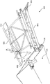
도 4 및 도 8에 도시된 바와 같이, 후방 프레임 섹션(320)은, 후방 프레임 섹션(320)의 하위 부분에 위치하는 제2 수평 축선(315)을 중심으로 회전하도록 구성된다. 제2 수평 축선(315)은 후방 프레임 섹션(320)의 길이를 따라 실질적으로 평행하게 연장된다. 후방 프레임 섹션(320)은 제2 수평 축선(315)을 중심으로 각도(γ)만큼 회전하도록 구성될 수 있다. 각도(γ)는 예컨대 약 0 내지 80 도일 수 있다. 후방 프레임 섹션(320)이 제2 수평 축선(315)을 중심으로 회전하면, 후방 프레임 섹션(320)이 제1 날개(301) 및 제2 날개(302)(도시되어 있지 않음)의 하위 표면 아래로 떨어지며, 이에 따라 제1 날개(301) 및 제2 날개(302)가 제1 수직 축선(321) 및 제2 수직 축선(322)을 중심으로 서로를 향해 회전하는 경우, 제1 날개(301) 및 제2 날개(302)는 (예컨대, 지상 모드로의 천이 중에) 후방 프레임 섹션(320) 위로 후퇴하게 된다. 예시적인 실시예에 따르면, 후방 프레임 섹션(320)이 제2 수평 축선(315)을 중심으로 회전되게 하도록 하나 이상의 액추에이터 메커니즘이 구성된다. 예를 들면, 도 4에 도시된 바와 같은 제4 액추에이터(344)는 연장 및 후퇴하도록 구성되어 후방 프레임 섹션(320)의 회전을 유발한다. 제4 액추에이터(344)는 일 단부에서 후방 프레임 섹션(320)의 상위 부재에 연결되는 반면, 타 단부에서 구조 프레임(도시되어 있지 않음)에 연결된다.As shown in FIGS. 4 and 8, the
도 4에 도시된 바와 같이, 제3 수평 축선(316)은 제1 날개(301) 및 제2 날개(302)의 길이를 따라 연장된다. 제1 날개(301)은, 하나 이상의 보조날개(131) 및 플랩(flap)이 제3 수평 축선(316)을 중심으로 회전하게 구성되어 보조 날개 및 플랩이 제1 날개(301)의 상위 전방 부분 위로 절첩됨으로써 제1 날개(301)의 깊이를 감소시키게 되도록 구성된다. 제2 날개(302)는 동등하게 구성된다. 제1 날개(301) 및 제2 날개(302)의 깊이를 감소시키면, 지상 작동 모드를 위해 후퇴될 때 날개(130)의 폭을 감소시키는 것이 가능하게 된다. 보조날개(131) 및 플랩은 하나 이상의 액추에이터 메커니즘에 의해 제3 수평 축선(316)을 중심으로 회전하게 구성된다. 예를 들면, 제5 액추에이터(345)는, 제1 날개(301)의 제3 수평 축선(316)을 중심으로 보조날개(131) 및 플랩을 회전시키도록 구성된다. 제6 액추에이터(346)는, 제2 날개(302)의 제3 수평 축선(316)을 중심으로 보조날개(131) 및 플랩을 회전시키도록 구성된다.As shown in FIG. 4, the third
본원에 설명되는 액추에이터는 당업계에 알려진 전기적 소스(electric source), 유압식 소스, 공압식 소스 또는 다른 소스일 수 있다. 또한, 본원에 설명되어 있는 수직 축선 및 수평 축선을 중심으로 한 회전을 유발하기 위해 다른 메커니즘이 사용될 수 있다는 것이 고려된다. 예를 들면, 기어, 레버, 케이블 등이 있다. 운송체(100)가 각각의 액추에이터를 개별적으로 그리고 독립적으로 작동시키도록 구성되거나, 또는 2개 이상의 액추에이터가 그 작동에 있어서 동기화될 수 있다. 예를 들어, 예시적인 일 실시예에 따르면, 제1 액추에이터(341), 제2 액추에이터(342), 및 제3 액추에이터(343)는 일 구간 동안 동시에 작동하도록 구성된다. 또 다른 실시예에 있어서, 공중 작동 모드로부터 지상 작동 모드로의 천이 시에, 운송체(100)는 제1 액추에이터(341), 제2 액추에이터(342), 및 제3 액추에이터(343)를 작동시키기에 앞서, 제4 액추에이터(344), 제5 액추에이터(345), 및 제6 액추에이터(346)를 작동시키도록 구성된다. 반대로, 지상 작동 모드로부터 공중 작동 모드로의 천이 시에, 운송체(100)는 제4 액추에이터(344), 제5 액추에이터(345), 및 제6 액추에이터(346)을 작동시키기에 앞서, 제1 액추에이터(341), 제2 액추에이터(342), 및 제3 액추에이터(343)를 작동시키도록 구성된다. The actuator described herein may be an electric source, a hydraulic source, a pneumatic source or other source known in the art. It is also contemplated that other mechanisms may be used to cause rotations about the vertical and horizontal axes described herein. For example, gears, levers, and cables. The
본원에 설명되는 중앙 날개 패널 및 방법에 대해 다양한 변형 및 변경이 행해질 수 있다. 동시에, 기재의 적절한 위치에 있어서, 용어 “회전”은 용어 “턴(turn)” 또는 “1/2 턴”으로 대체될 수 있다.Various modifications and variations can be made to the central wing panels and methods described herein. At the same time, in the proper position of the substrate, the term " rotation " may be replaced by the terms " turn "
Claims (16)
- 본체의 길이방향 축선과 실질적으로 정렬되도록 본체에 연결되는 지지 구조;
- 상기 지지 구조의 전방 부분에 장착되는 전방 횡방향 부재 및 상기 지지 구조의 후방 부분에 장착되는 후방 횡방향 부재로서, 상기 전방 횡방향 부재 및 후방 횡방향 부재는 각각 본체의 길이방향 축선에 대해 수직하며 실질적으로 수평인 회전 축선을 갖는 것인 전방 횡방향 부재 및 후방 횡방향 부재;
- 상기 전방 횡방향 부재에 연결되고 전방 횡방향 부재의 회전 축선을 중심으로 회전 가능한 날개 지지 부재로서, 상기 날개 지지 부재에는 날개 피봇 커넥터(wing pivot connector)가 마련되며, 이 날개 피봇 커넥터에 의해 각각의 날개의 전방 부분은 날개 지지 부재에 연결되고, 각각의 날개는, 날개가 본체로부터 실질적으로 수평으로 연장되는 위치인 제1 날개 위치와, 날개가 본체의 길이방향 축선에 실질적으로 수평으로 평행하게 되는 위치인 제2 날개 위치 사이에서 각각의 커넥터의 실질적으로 수직인 축선을 중심으로 피봇 가능한 것인 날개 지지 부재;
- 상기 후방 횡방향 부재에 연결되는 날개 잠금 부재로서, 날개 잠금 부재는 잠금 위치와 해제 위치 사이에서 후방 횡방향 부재를 중심으로 한 회전에 의해 이동 가능하며, 상기 잠금 위치는, 날개가 제1 날개 위치로부터 제2 날개 위치로 이동하는 것을 방지하도록 날개 잠금 부재 상의 잠금 세그먼트가 각각의 날개의 후방 부분에서의 대응하는 잠금 세그먼트와 결합하는 위치이고, 상기 해제 위치는 제1 날개 위치로부터 제2 날개 위치로의 날개의 이동을 허용하도록 잠금 세그먼트가 대응하는 잠금 세그먼트로부터 분리되는 위치인 것인 날개 잠금 부재;
- 제1 날개 위치에 있을 때 날개의 입사각을 조정하도록 전방 횡방향 부재의 회전 축선을 중심으로 지지 구조를 피봇시키기 위한 액추에이터
를 포함하는 중앙 날개 패널.A central wing panel for a vehicle, comprising a body and wings positioned on each side of the body,
A support structure connected to the body such that it is substantially aligned with a longitudinal axis of the body;
A front transverse member mounted on a front portion of the support structure and a rear transverse member mounted on a rear portion of the support structure, the front transverse member and the rear transverse member being each perpendicular to a longitudinal axis of the body, A front transverse member and a rear transverse member having a substantially horizontal axis of rotation;
A wing support member connected to the front transverse member and rotatable about a rotation axis of the front transverse member, the wing support member being provided with a wing pivot connector, the wing pivot connector Each wing having a first wing position in which the wings extend substantially horizontally from the body and a second wing position in which the wings are substantially parallel to the longitudinal axis of the body A wing support member pivotable about a substantially vertical axis of each connector between a first wing position and a second wing position;
- a wing locking member connected to said rearward transverse member, said wing locking member being movable by rotation about a rear transverse member between a locking position and an unlocking position, Wherein the locking segment on the wing-lock member engages with a corresponding locking segment in a rear portion of each wing to prevent movement of the locking member from a first wing position to a second wing position, The wing lock member being a position in which the locking segment is disengaged from the corresponding locking segment to permit movement of the wing into the locking segment;
An actuator for pivoting the support structure about the axis of rotation of the front transverse member to adjust the angle of incidence of the wings when in the first wing position
And a central wing panel including the central wing panel.
- 날개 피봇 커넥터는 전방 프레임 섹션의 대향 단부 부근에 위치 설정되며, 후방 프레임 섹션은 잠금 위치와 해제 위치 사이에서 후방 횡방향 부재의 회전 축선을 중심으로 회전하도록 구성되는 것을 특징으로 하는 중앙 날개 패널.2. The apparatus of claim 1 wherein the support structure includes a front frame section forming a front transverse member and a wing support member and a rear frame section forming a rear transverse member and a wing locking member, The sections are connected by one or more cross members,
The wing pivot connector is positioned near the opposite end of the front frame section and the rear frame section is configured to rotate about the axis of rotation of the rear transverse member between the locked and unlocked positions.
제1 날개 위치와 제2 날개 위치 사이에서 날개를 이동시키기 위한 적어도 제1의 추가적인 액추에이터
를 더 포함하는 것을 특징으로 하는 중앙 날개 패널.3. The method according to claim 1 or 2,
At least a first additional actuator for moving the wing between the first wing position and the second wing position,
Further comprising a central wing panel.
후방 프레임 섹션에 결합되며 후방 횡방향 부재의 회전 축선을 중심으로 후방 프레임 섹션을 회전시키도록 구성되는 적어도 제2의 추가적인 액추에이터
를 더 포함하는 것을 특징으로 하는 중앙 날개 패널.3. The method of claim 2,
At least a second additional actuator coupled to the rear frame section and configured to rotate the rear frame section about a rotational axis of the rear transverse member,
Further comprising a central wing panel.
상기 전개 위치와 상기 절첩 위치 사이에서 보조날개 및 플랩을 회전시키기 위한 적어도 하나의 액추에이터
를 더 포함하는 것을 특징으로 하는 하이브리드 운송 수단.10. The method of claim 9,
At least one actuator for rotating the auxiliary vane and the flap between the deployed position and the folded position,
Further comprising: a hybrid vehicle.
- 잠금 위치로부터 해제 위치로 날개 잠금 부재를 회전시키는 단계;
- 제1 날개 위치와 제2 날개 위치 사이에서 각각의 날개 피봇 커넥터를 중심으로 각각의 날개를 회전시키는 단계;
- 날개가 제1 날개 위치와 제2 날개 위치 사이에서 이동하는 동안 지지 구조를 틸팅(tilting)시키도록 액추에이터를 작동시키는 단계
를 포함하는 것을 특징으로 하는 방법.11. A method of operating a means according to any one of claims 7 to 10, wherein the blades are initially in a first wing position,
Rotating the blade lock member from the locked position to the unlocked position;
Rotating each wing about a respective wing pivot connector between a first wing position and a second wing position;
- actuating the actuator to tilting the support structure while the wing is moving between the first wing position and the second wing position
≪ / RTI >
전개 위치(deployed position)와 절첩 위치(folded position) 사이에서 후미 에지를 따라 연장되는 축선을 중심으로 보조날개 및 플랩을 회전시키는 단계로서, 상기 전개 위치는, 날개가 초기에 제1 날개 위치에 있을 때 보조날개 및 플랩이 후미 에지로부터 연장되는 위치이고, 상기 절첩 위치는, 날개가 제2 날개 위치로 이동을 개시할 때 보조날개 및 플랩이 날개의 상위 표면 위에 놓이는 위치인 것인 단계
를 포함하는 것을 특징으로 하는 방법.12. The method of claim 11, wherein each wing comprises a set of auxiliary wings and a set of flaps connected to the trailing edge,
Rotating an auxiliary wing and a flap about an axis extending along a trailing edge between a deployed position and a folded position, the deployed position being such that the wing is initially in a first wing position Wherein the auxiliary wing and flap extend from the trailing edge and the folded position is a position where the auxiliary wing and flap rest on the upper surface of the wing when the wing begins to move into the second wing position
≪ / RTI >
- 제2 날개 위치와 제1 날개 위치 사이에서 각각의 날개 피봇 커넥터를 중심으로 각각의 날개를 회전시키는 단계;
- 날개가 제2 날개 위치와 제1 날개 위치 사이에서 이동하는 동안 지지 구조를 틸팅(tilting)시키도록 액추에이터를 작동시키는 단계;
- 해제 위치로부터 잠금 위치로 날개 잠금 부재를 회전시키는 단계
를 포함하는 것을 특징으로 하는 방법.11. A method of operating a device according to any one of claims 7 to 10, wherein the blades are initially in a second wing position,
Rotating each wing about a respective wing pivot connector between a second wing position and a first wing position;
Actuating the actuator to tilt the support structure while the wing is moving between the second wing position and the first wing position;
- rotating the wing lock member from the unlocked position to the locked position
≪ / RTI >
절첩 위치(folded position)와 전개 위치(deployed position) 사이에서 후미 에지를 따라 연장되는 축선을 중심으로 보조날개 및 플랩을 회전시키는 단계로서, 상기 절첩 위치는, 날개가 제2 날개 위치에 있을 때 보조날개 및 플랩이 날개의 상위 표면 위에 놓이는 위치이며, 상기 전개 위치는, 날개가 제1 날개 위치로 이동할 때 보조날개 및 플랩이 후미 에지로부터 연장되는 위치인 것인 단계
를 포함하는 것을 특징으로 하는 방법.14. The method of claim 13, wherein each wing comprises a set of auxiliary wings and a set of flaps connected to the trailing edge thereof,
Rotating an auxiliary wing and a flap about an axis extending along a trailing edge between a folded position and an deployed position, Wherein the wings and the flap are located on an upper surface of the wing, the deployed position being a position where the wing and the flap extend from the trailing edge when the wing moves to the first wing position
≪ / RTI >
제1 날개 위치에 대한 날개의 이동에 후속하여, 상기 수단의 이동 방향으로 사전에 정해진 받음각을 나타내도록 날개의 입사(incidence)를 조정하게 상기 구조물을 틸팅시키기 위해 액추에이터를 작동시키는 단계
를 포함하는 것을 특징으로 하는 방법.The method according to claim 13 or 14,
Actuating the actuator to tilt the structure to adjust the incidence of the wing to follow a movement of the wing relative to the first wing position to exhibit a predefined angle of attack in the direction of movement of the means
≪ / RTI >
를 더 포함하는 것을 특징으로 하는 방법.
16. A device according to any one of claims 11 to 15, characterized in that the wings are arranged in the first wing position so as to clear any vertical ring section of the means as the wing moves between the first wing position and the second wing position. Actuating the actuator to tilt the support structure during movement between the first wing position and the second wing position
≪ / RTI >
Applications Claiming Priority (5)
| Application Number | Priority Date | Filing Date | Title |
|---|---|---|---|
| SKPP50058-2014 | 2014-10-08 | ||
| SKPUV50123-2014 | 2014-10-08 | ||
| SK50123-2014U SK7493Y1 (en) | 2014-10-08 | 2014-10-08 | Center of the flying vehicle and its control |
| SK50058-2014A SK288638B6 (en) | 2014-10-08 | 2014-10-08 | Center of the flying vehicle and its control |
| PCT/SK2015/000004 WO2016057004A1 (en) | 2014-10-08 | 2015-10-08 | Central wing panel for a flying vehicle and method of its control |
Publications (1)
| Publication Number | Publication Date |
|---|---|
| KR20170066563A true KR20170066563A (en) | 2017-06-14 |
Family
ID=60084164
Family Applications (1)
| Application Number | Title | Priority Date | Filing Date |
|---|---|---|---|
| KR1020177012129A KR20170066563A (en) | 2014-10-08 | 2015-10-08 | Central wing panel for a flying vehicle and method on its control |
Country Status (8)
| Country | Link |
|---|---|
| US (1) | US10611459B2 (en) |
| EP (1) | EP3204246B1 (en) |
| JP (1) | JP2017534515A (en) |
| KR (1) | KR20170066563A (en) |
| CN (1) | CN107107690B (en) |
| BR (1) | BR112017006721A2 (en) |
| RU (1) | RU2687543C2 (en) |
| WO (1) | WO2016057004A1 (en) |
Families Citing this family (9)
| Publication number | Priority date | Publication date | Assignee | Title |
|---|---|---|---|---|
| DE102016006696A1 (en) | 2016-05-27 | 2017-11-30 | Christoph Jaeger | Flight Car System |
| US20180079488A1 (en) * | 2016-09-21 | 2018-03-22 | Bell Helicopter Textron Inc. | Foldable aircraft with anhedral stabilizing wings |
| EP3335914B1 (en) | 2016-12-13 | 2019-11-13 | AeroMobil R&D, s. r. o. | Vehicle including control pedal arrangement |
| EP3335915B1 (en) | 2016-12-13 | 2019-12-04 | AeroMobil R&D, s. r. o. | Stability control for operation of a convertible air - road vehicle |
| EP3335916A1 (en) | 2016-12-13 | 2018-06-20 | AeroMobil R&D, s. r. o. | Acceleration control for a convertible air - road vehicle |
| EP3366570A1 (en) | 2017-02-22 | 2018-08-29 | AeroMobil R&D, s. r. o. | Wing folding |
| EP3412560B1 (en) | 2017-06-05 | 2020-02-12 | AeroMobil R&D, s. r. o. | Wing folding |
| EP3418184A1 (en) | 2017-06-20 | 2018-12-26 | AeroMobil R&D, s. r. o. | Wing flap system for flying car |
| JP7265260B2 (en) * | 2019-09-17 | 2023-04-26 | 国立研究開発法人宇宙航空研究開発機構 | aircraft |
Family Cites Families (18)
| Publication number | Priority date | Publication date | Assignee | Title |
|---|---|---|---|---|
| GB556478A (en) | 1942-04-04 | 1943-10-06 | Osmond Ernst Fletcher | Improvements in or relating to aircraft wings |
| US2692095A (en) * | 1952-08-01 | 1954-10-19 | Fred A Carpenter | Convertible airplane and highway vehicle |
| US2940688A (en) * | 1956-08-27 | 1960-06-14 | Edward F Bland | Roadable aircraft and sailboat |
| FR2577198A1 (en) | 1985-02-13 | 1986-08-14 | Bazin Claudine | CONVERTIBLE AIRPLANE |
| US4881700A (en) * | 1988-01-05 | 1989-11-21 | Branko Sarh | Convertible fixed wing aircraft |
| RU2058911C1 (en) * | 1988-06-15 | 1996-04-27 | Казанский государственный технический университет им.А.Н.Туполева | Swivel unit for folding wing at basing |
| JPH0338499A (en) * | 1989-07-03 | 1991-02-19 | Mitsubishi Heavy Ind Ltd | Aircraft having changeable main wing |
| JPH04297798A (en) * | 1991-03-04 | 1992-10-21 | Mitsubishi Electric Corp | Guided missile |
| DE4119613C2 (en) * | 1991-06-14 | 1997-03-27 | Diehl Gmbh & Co | Missiles with fold-out guidance devices |
| US7946527B2 (en) * | 2007-09-10 | 2011-05-24 | Alan Glen Holmes | Aircraft with fixed, swinging and folding wings |
| US8157206B2 (en) * | 2008-06-11 | 2012-04-17 | Icon Aircraft, Inc. | Two-motion wing-fold mechanism with independent load path |
| CN102137768B (en) * | 2008-07-28 | 2016-04-06 | 弗莱克健康理念股份有限公司 | The all-round vehicle of aeroamphibious |
| US8464979B2 (en) | 2009-06-02 | 2013-06-18 | Sunstar IM | Foldable swan-wings aircraft |
| RU2403177C1 (en) | 2009-07-31 | 2010-11-10 | Общество С Ограниченной Ответственностью "Научно-Производственная Фирма "Сигма-Тс" | Aircraft with folding wing and device for aircraft wing folding |
| US8162253B2 (en) * | 2009-08-19 | 2012-04-24 | Seiford Sr Donald S | Convertible vehicle for road, air, and water usage |
| JP5960139B2 (en) * | 2010-08-03 | 2016-08-02 | サムソン エーアイピー、インク. | Retractable wing hinges and trusses for flying vehicles |
| SK288242B6 (en) * | 2011-08-30 | 2015-02-03 | Aeromobil, S.R.O. | Method of transformation of hybrid vehicles for land and air and hybrid vehicle |
| CN102616096A (en) * | 2012-04-24 | 2012-08-01 | 赵辉 | Solar flying automobile with folding wings |
-
2015
- 2015-10-08 US US15/517,545 patent/US10611459B2/en not_active Expired - Fee Related
- 2015-10-08 CN CN201580054659.8A patent/CN107107690B/en not_active Expired - Fee Related
- 2015-10-08 EP EP15801514.9A patent/EP3204246B1/en not_active Not-in-force
- 2015-10-08 BR BR112017006721A patent/BR112017006721A2/en not_active Application Discontinuation
- 2015-10-08 WO PCT/SK2015/000004 patent/WO2016057004A1/en active Application Filing
- 2015-10-08 KR KR1020177012129A patent/KR20170066563A/en unknown
- 2015-10-08 RU RU2017115995A patent/RU2687543C2/en not_active IP Right Cessation
- 2015-10-08 JP JP2017518523A patent/JP2017534515A/en not_active Ceased
Also Published As
| Publication number | Publication date |
|---|---|
| US10611459B2 (en) | 2020-04-07 |
| RU2017115995A (en) | 2018-11-13 |
| CN107107690B (en) | 2019-10-08 |
| JP2017534515A (en) | 2017-11-24 |
| CN107107690A (en) | 2017-08-29 |
| BR112017006721A2 (en) | 2017-12-19 |
| WO2016057004A1 (en) | 2016-04-14 |
| RU2687543C2 (en) | 2019-05-14 |
| EP3204246A1 (en) | 2017-08-16 |
| WO2016057004A8 (en) | 2017-04-20 |
| RU2017115995A3 (en) | 2019-03-04 |
| US20170305527A1 (en) | 2017-10-26 |
| EP3204246B1 (en) | 2019-06-05 |
Similar Documents
| Publication | Publication Date | Title |
|---|---|---|
| KR20170066563A (en) | Central wing panel for a flying vehicle and method on its control | |
| RU2686803C2 (en) | Dirension control system and method for hybrid vehicle of air and ground transport | |
| JP7232834B2 (en) | Wing tilt actuation system for electric vertical take-off and landing (VTOL) aircraft | |
| US9254916B2 (en) | Vertical take-off and landing aircraft with tiltrotor power for use on land and in air | |
| US3666209A (en) | V/stol aircraft with variable tilt wing | |
| JP2001213397A (en) | Improvement of aircraft | |
| US11858304B2 (en) | Multi-modal vehicle | |
| EP3768592B1 (en) | A structure construction for an aircraft and aircraft comprising the structure construction | |
| RU2758223C2 (en) | Method for transforming motor vehicle for land and air transportation, motor vehicle | |
| GB2550489A (en) | An unmanned aerial vehicle | |
| WO2018200879A1 (en) | Electrically powered vtol tail-sitter aircraft for providing transportation | |
| EP3763620B1 (en) | Flap actuation system for aircraft | |
| US20190256193A1 (en) | Folding propeller | |
| EP3209559B1 (en) | Aircraft | |
| SK501232014U1 (en) | Center of the flying vehicle and its control | |
| SK500582014A3 (en) | Center of the flying vehicle and its control | |
| EP3363735B1 (en) | Undercarriage-mounted airfoil | |
| SK7646Y1 (en) | System and method of controlling the direction of the hybrid transportation vehicle for air and ground | |
| SK500592014A3 (en) | System and method of controlling the direction of the hybrid vehicle for air and land | |
| WO2023208887A1 (en) | Aeronautical vehicle and method of transitioning between flight modes for an aeronautical vehicle | |
| PL232733B1 (en) | Unmanned aerial vehicle |