KR20170047771A - Wearable terminal - Google Patents
Wearable terminal Download PDFInfo
- Publication number
- KR20170047771A KR20170047771A KR1020150148247A KR20150148247A KR20170047771A KR 20170047771 A KR20170047771 A KR 20170047771A KR 1020150148247 A KR1020150148247 A KR 1020150148247A KR 20150148247 A KR20150148247 A KR 20150148247A KR 20170047771 A KR20170047771 A KR 20170047771A
- Authority
- KR
- South Korea
- Prior art keywords
- main body
- frame
- wearable terminal
- clip
- connection
- Prior art date
Links
Images


Classifications
-
- G—PHYSICS
- G06—COMPUTING; CALCULATING OR COUNTING
- G06F—ELECTRIC DIGITAL DATA PROCESSING
- G06F3/00—Input arrangements for transferring data to be processed into a form capable of being handled by the computer; Output arrangements for transferring data from processing unit to output unit, e.g. interface arrangements
- G06F3/01—Input arrangements or combined input and output arrangements for interaction between user and computer
-
- G—PHYSICS
- G04—HOROLOGY
- G04G—ELECTRONIC TIME-PIECES
- G04G21/00—Input or output devices integrated in time-pieces
-
- G—PHYSICS
- G06—COMPUTING; CALCULATING OR COUNTING
- G06F—ELECTRIC DIGITAL DATA PROCESSING
- G06F1/00—Details not covered by groups G06F3/00 - G06F13/00 and G06F21/00
- G06F1/16—Constructional details or arrangements
- G06F1/1613—Constructional details or arrangements for portable computers
- G06F1/163—Wearable computers, e.g. on a belt
Landscapes
- Engineering & Computer Science (AREA)
- Theoretical Computer Science (AREA)
- General Engineering & Computer Science (AREA)
- Physics & Mathematics (AREA)
- General Physics & Mathematics (AREA)
- Human Computer Interaction (AREA)
- Computer Hardware Design (AREA)
- Telephone Set Structure (AREA)
Abstract
A main body on which a main board is mounted; A main body seating portion in which the main body is inserted in a thickness direction, a frame surrounding the side surface of the main body; And a band extending from the frame and securing to the body of the user; A switch that is turned on or off when the main body is inserted into the main body seating portion; The wearable terminal includes a controller for providing visual or auditory notification to a user when the state of the switch is changed. The wearable terminal of the separate wearable terminal can expand the function of the main body by incorporating electronic parts in the band.
Description
The present invention relates to a wearable terminal capable of detaching a body from a band.
A terminal can be divided into a mobile terminal (mobile / portable terminal) and a stationary terminal according to whether the terminal can be moved. The mobile terminal can be divided into a handheld terminal and a vehicle mounted terminal according to whether the user can directly carry the mobile terminal.
The functions of mobile terminals are diversified. For example, there are data and voice communication, photographing and video shooting through a camera, voice recording, music file playback through a speaker system, and outputting an image or video on a display unit. Some terminals are equipped with an electronic game play function or a multimedia player function. In particular, modern mobile terminals can receive multicast signals that provide visual content such as broadcast and video or television programs.
Such a terminal has various functions, for example, in the form of a multimedia device having multiple functions such as photographing and photographing of a moving picture, reproduction of a music or video file, reception of a game and broadcasting, etc. .
In addition, while being regarded as personal items, various designs are applied to the portable terminal to express its own personality.
The mechanical form of a traditional handheld terminal is sized to hold the device by hand, carried by carrying it in a bag or pocket. Such a portable terminal is liable to be damaged due to loss, drop, or the like, and there is an inconvenience of carrying.
In recent years, various types of wearable terminals have appeared, such as wearing a portable terminal like a wrist watch, hanging on a necklace, or taking a seat on a waist. The wearable terminal may vary in size and function depending on the wearing form, and various types of wearable terminals may be used according to the needs of the user.
SUMMARY OF THE INVENTION It is an object of the present invention to provide a watch-type mobile terminal in which a main body can be detached from a band and durability of a connecting pin located in a lateral direction is improved.
A main body on which a main board is mounted; A main body seating portion in which the main body is inserted in a thickness direction, a frame surrounding the side surface of the main body; And a band extending from the frame and securing to the body of the user; A switch that is turned on or off when the main body is inserted into the main body seating portion; And a control unit for providing visual or auditory notification to the user when the state of the switch is changed.
Further comprising a magnet located in the frame, wherein the switch can use a hall sensor for sensing a magnetic change.
The magnet is located in a magnet housing protruding from the inside of the frame, and the main body can be formed with a concave portion corresponding to the magnet housing.
A sensing clip projecting laterally from the inner side of the frame; And a connection pin connected to the main board and exposed to a side surface of the main body and contacting with the sensor clip, wherein the controller controls the user to visually or audibly Notifications can be provided.
The sensing clip is formed by bending a metal plate, the sensing clip including: a base fixed to the flexible substrate; A first link extending in a U-shape in the base; A connecting portion having an inclined surface and projecting from an inner surface of the frame; And a second link located between the first link and the connecting portion and bent in an S-shape twice.
The sensing clip may include a sidewall portion bent from the base; And a first cover folded again at the side wall portion to cover the second link.
And a second cover folded at the side wall portion to cover an end portion of the connection portion.
The end of the connection may extend alongside the base.
According to at least one of the embodiments of the present invention, in the separate wearable terminal, the functions of the main body can be expanded by incorporating electronic parts in the band. Further, the shape of the connection clip of the body and the frame is improved, and the durability is improved.
In addition, it is possible to prevent the risk of loss by sensing that the main body is separated from the frame.
Further scope of applicability of the present invention will become apparent from the following detailed description. It should be understood, however, that the detailed description and specific examples, such as the preferred embodiments of the invention, are given by way of illustration only, since various changes and modifications within the spirit and scope of the invention will become apparent to those skilled in the art.
1 is a block diagram for explaining a wearable terminal related to the present invention.
2 is a perspective view of a wearable terminal according to one embodiment of the present invention.
FIG. 3 is a view showing a state where the body of the wearable terminal of FIG. 2 is separated from the frame.
4 is a view showing connection pin portions of a wearable terminal according to the present invention.
5 is a view showing a connection clip portion of a wearable terminal according to the present invention.
6 is a cross-sectional view illustrating a wearable terminal related to the present invention.
7 is an exploded perspective view showing a flexible substrate, a first frame, and a second frame of a wearable terminal related to the present invention.
8 is a view showing a front surface and a back surface of a connection clip portion of a flexible substrate of a wearable terminal according to the present invention.
9 is a view showing a connection clip of the wearable terminal related to the present invention.
10 is a view for explaining a comparison between a connection clip of a wearable terminal and a conventional connection pin according to the present invention.
11 is a cross-sectional view illustrating an embodiment of a coupling detection sensor of a wearable terminal related to the present invention.
12 and 13 are views showing another embodiment of a coupling detection sensor of a wearable terminal related to the present invention.
Hereinafter, embodiments of the present invention will be described in detail with reference to the accompanying drawings, wherein like reference numerals are used to designate identical or similar elements, and redundant description thereof will be omitted. The suffix "module" and " part "for the components used in the following description are given or mixed in consideration of ease of specification, and do not have their own meaning or role. In the following description of the embodiments of the present invention, a detailed description of related arts will be omitted when it is determined that the gist of the embodiments disclosed herein may be blurred. It is to be understood that both the foregoing general description and the following detailed description are exemplary and explanatory and are intended to provide further explanation of the invention as claimed. , ≪ / RTI > equivalents, and alternatives.
Terms including ordinals, such as first, second, etc., may be used to describe various elements, but the elements are not limited to these terms. The terms are used only for the purpose of distinguishing one component from another.
It is to be understood that when an element is referred to as being "connected" or "connected" to another element, it may be directly connected or connected to the other element, . On the other hand, when an element is referred to as being "directly connected" or "directly connected" to another element, it should be understood that there are no other elements in between.
The singular expressions include plural expressions unless the context clearly dictates otherwise.
In the present application, the terms "comprises", "having", and the like are used to specify that a feature, a number, a step, an operation, an element, a component, But do not preclude the presence or addition of one or more other features, integers, steps, operations, elements, components, or combinations thereof.
1 is a block diagram for explaining a
The
More specifically, the
The
The
The
And may further include a coupling detection sensor for detecting whether or not a specific part is detached. When the
The
The
In addition, the
The
In addition, the
The
At least some of the components may operate in cooperation with one another to implement the method of operation, control, or control of the
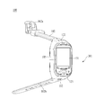
FIG. 2 is a perspective view showing an embodiment of a
The
These
Meanwhile, the
The
A
The
The
The
In addition, the
The
The touch sensor may be a film having a touch pattern and disposed between the window 151a and a display (not shown) on the rear surface of the window 151a, or may be a metal wire . Alternatively, the touch sensor may be formed integrally with the display. For example, the touch sensor may be disposed on a substrate of the display or inside the display.
As described above, the
The
The
The
The
The
The
The
The
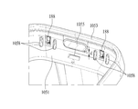
4 is a view showing a
Electronic components may be mounted on the
The function of the
A
One end of the
A ring-shaped
The
The
The
It is possible to form an
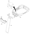
7 is an exploded perspective view showing a
7, one side of the
One end of the
In order to form the flexible molded
A
Conversely, the fixing
The
The
In order to prevent this, an engaging
FIG. 9 is a view showing a
The
The link has a curved line and is a part whose shape is changed corresponding to the change of the position of the
Figs. 10 (a) and 10 (b) are conventionally used connection clips, and the link includes only the
However, when the connecting clip is arranged in the lateral direction as shown in Fig. 10 (b) and the connecting pin opposing from the upper side to the lower side is inserted, deformation occurs at a position B different from the portion (A) Occurs. The portion B where the deformation occurs is disposed adjacent to the
That is, there is a problem that the durability of the connection clip is deteriorated because the fatigue of the connection clip increases. In order to solve the above problem, the present invention additionally adds an S-shaped
The deformation degree of the deformed portion C of Fig. 9 (b) is smaller than that of the deformed portion B of Fig. 10 (b), and the fatigue applied to the connecting
The
In the conventional connection clip shown in Fig. 10 (a), the
11 is a cross-sectional view showing a
The
The magnet may be located in the magnet housing 1054a protruding from the inside of the
When the
12 and 13 are views showing another embodiment of the
However, if an antenna or a ground is formed on the flexible substrate and connected to the
The sensing clip 1458 may have the same structure as the
The sensing clip 1458 separated from the
When the sensing clip 1458 is detached from the
As described above, according to at least one embodiment of the present invention, the function of the
In addition, it is possible to prevent the risk of loss by sensing that the
The foregoing detailed description should not be construed in all aspects as limiting and should be considered illustrative. The scope of the present invention should be determined by rational interpretation of the appended claims, and all changes within the scope of equivalents of the present invention are included in the scope of the present invention.
100: Wearable terminal 101: Body
1013: guide groove 102: band
105: frame 1051: first frame
1052: Second frame 1053: Flexible injection molding
1055: Acoustic hole 1056: Combined concave and convex
1057: engaging projection
1058: Guide protrusion 1059: Fixing groove
110: wireless communication unit 120: input unit
140: sensing unit 150: output unit
160: interface unit 170: memory
180: control unit 190: power supply unit
183: Connection pin 184: Waterproof part
185: main substrate 186: flexible substrate
1867: Coupling hole 1869: Fixing projection
188: connection clip 1881: base
1882: first link 1883: connection
1884: second link 1886: first cover
1887: second cover 189: reinforcing plate
1451: Magnet 1452: Hall sensor
1453: sensing pin 1458: sensing clip
Claims (8)
A main body seating portion in which the main body is inserted in a thickness direction, a frame surrounding the side surface of the main body; And
A band extending from the frame and securing to the body of the user;
A switch that is turned on or off when the main body is inserted into the main body seating portion;
And providing a visual or auditory notification to a user when the state of the switch is changed.
Further comprising a magnet located in said frame,
Wherein the switch is a hall sensor for detecting a change in magnetic field.
The magnet being located in a magnet housing protruding from the inside of the frame,
Wherein the main body has a concave portion corresponding to the magnet housing.
A sensing clip projecting laterally from the inner side of the frame; And
And a connection pin connected to the main board and exposed to a side surface of the main body and contacting the sensor clip,
Wherein the control unit provides a visual or audible notification to a user when the contact state of the sensing pin and the sensing pin is released.
The sensing clip is formed by folding a metal plate,
The sensing clip may include:
A base fixed to the flexible substrate;
A first link extending in a U-shape in the base;
A connecting portion having an inclined surface and projecting from an inner surface of the frame; And
And a second link located between the first link and the connection part and bent in an S-shape twice.
The sensing clip may include:
A side wall portion bent from the base; And
And a first cover folded again at the side wall portion to cover the second link.
And a second cover folded at the side wall portion to cover an end portion of the connection portion.
And the end of the connection portion extends in parallel with the base.
Priority Applications (1)
| Application Number | Priority Date | Filing Date | Title |
|---|---|---|---|
| KR1020150148247A KR20170047771A (en) | 2015-10-23 | 2015-10-23 | Wearable terminal |
Applications Claiming Priority (1)
| Application Number | Priority Date | Filing Date | Title |
|---|---|---|---|
| KR1020150148247A KR20170047771A (en) | 2015-10-23 | 2015-10-23 | Wearable terminal |
Publications (1)
| Publication Number | Publication Date |
|---|---|
| KR20170047771A true KR20170047771A (en) | 2017-05-08 |
Family
ID=60163766
Family Applications (1)
| Application Number | Title | Priority Date | Filing Date |
|---|---|---|---|
| KR1020150148247A KR20170047771A (en) | 2015-10-23 | 2015-10-23 | Wearable terminal |
Country Status (1)
| Country | Link |
|---|---|
| KR (1) | KR20170047771A (en) |
Cited By (4)
| Publication number | Priority date | Publication date | Assignee | Title |
|---|---|---|---|---|
| CN107370920A (en) * | 2017-07-12 | 2017-11-21 | 成都西可科技有限公司 | A kind of imaging terminal and its control method |
| KR20200114525A (en) * | 2019-03-29 | 2020-10-07 | (주)파트론 | Wearable device |
| WO2023017982A1 (en) * | 2021-08-09 | 2023-02-16 | 삼성전자주식회사 | Wearable electronic device |
| WO2024017162A1 (en) * | 2022-07-21 | 2024-01-25 | 华为技术有限公司 | Wearable apparatus |
-
2015
- 2015-10-23 KR KR1020150148247A patent/KR20170047771A/en unknown
Cited By (5)
| Publication number | Priority date | Publication date | Assignee | Title |
|---|---|---|---|---|
| CN107370920A (en) * | 2017-07-12 | 2017-11-21 | 成都西可科技有限公司 | A kind of imaging terminal and its control method |
| CN107370920B (en) * | 2017-07-12 | 2023-07-18 | 成都市喜爱科技有限公司 | Imaging terminal and control method thereof |
| KR20200114525A (en) * | 2019-03-29 | 2020-10-07 | (주)파트론 | Wearable device |
| WO2023017982A1 (en) * | 2021-08-09 | 2023-02-16 | 삼성전자주식회사 | Wearable electronic device |
| WO2024017162A1 (en) * | 2022-07-21 | 2024-01-25 | 华为技术有限公司 | Wearable apparatus |
Similar Documents
| Publication | Publication Date | Title |
|---|---|---|
| US10338638B2 (en) | Wearable smart device | |
| US9737119B2 (en) | Watch type terminal | |
| US8787006B2 (en) | Wrist-worn electronic device and methods therefor | |
| KR101587138B1 (en) | Mobile terminal | |
| US9577693B2 (en) | Bluetooth headset and wristwatch including the same | |
| KR102242979B1 (en) | Curved body and wearable device therewith | |
| US20160062392A1 (en) | Connection by securing device with integrated circuitry layer | |
| KR101759950B1 (en) | Mobile terminal | |
| EP3116202B1 (en) | Mobile terminal | |
| KR20100050031A (en) | Mobile terminal | |
| KR20160016153A (en) | Mobile terminal | |
| KR20170047771A (en) | Wearable terminal | |
| KR101637368B1 (en) | Watch type mobile terminal | |
| KR101659030B1 (en) | Terminal of watch type and mobile terminal assembly | |
| KR20170047770A (en) | Wearable terminal | |
| KR20190037738A (en) | Mobile terminal | |
| US20170078461A1 (en) | Mobile terminal | |
| KR20190037739A (en) | Mobile terminal | |
| KR20190037967A (en) | Mobile terminal | |
| KR20170021147A (en) | Mobile terminal | |
| KR20160070998A (en) | Wearable terminal | |
| KR20160137302A (en) | Wearable smart device | |
| KR20170084444A (en) | Mobile terminal | |
| KR20170017204A (en) | Connector and mobile terminal including the same | |
| KR20200019412A (en) | Mobile terminal |