KR20160145049A - System and method for non-contact optical-power measurement - Google Patents
System and method for non-contact optical-power measurement Download PDFInfo
- Publication number
- KR20160145049A KR20160145049A KR1020167030162A KR20167030162A KR20160145049A KR 20160145049 A KR20160145049 A KR 20160145049A KR 1020167030162 A KR1020167030162 A KR 1020167030162A KR 20167030162 A KR20167030162 A KR 20167030162A KR 20160145049 A KR20160145049 A KR 20160145049A
- Authority
- KR
- South Korea
- Prior art keywords
- fiber
- scattered
- optical
- light
- optical fiber
- Prior art date
Links
- 238000000034 method Methods 0.000 title claims abstract description 75
- 238000005259 measurement Methods 0.000 title description 19
- 239000000835 fiber Substances 0.000 claims abstract description 264
- 230000003287 optical effect Effects 0.000 claims abstract description 192
- 239000013307 optical fiber Substances 0.000 claims abstract description 180
- 238000005253 cladding Methods 0.000 claims abstract description 65
- 238000001514 detection method Methods 0.000 claims abstract description 61
- 238000003384 imaging method Methods 0.000 claims description 50
- 230000010287 polarization Effects 0.000 claims description 43
- 229940125730 polarisation modulator Drugs 0.000 claims description 19
- 238000001914 filtration Methods 0.000 claims description 9
- 230000008859 change Effects 0.000 abstract description 5
- 238000010586 diagram Methods 0.000 description 17
- 238000012544 monitoring process Methods 0.000 description 13
- 238000003860 storage Methods 0.000 description 12
- 239000004973 liquid crystal related substance Substances 0.000 description 11
- 238000012545 processing Methods 0.000 description 11
- 238000004891 communication Methods 0.000 description 9
- 238000000149 argon plasma sintering Methods 0.000 description 8
- 239000000047 product Substances 0.000 description 8
- 238000003780 insertion Methods 0.000 description 7
- 230000037431 insertion Effects 0.000 description 7
- 230000007547 defect Effects 0.000 description 6
- 230000007935 neutral effect Effects 0.000 description 5
- 230000001276 controlling effect Effects 0.000 description 4
- 230000000644 propagated effect Effects 0.000 description 4
- 230000001902 propagating effect Effects 0.000 description 4
- 230000004044 response Effects 0.000 description 4
- 238000012546 transfer Methods 0.000 description 4
- 229910000530 Gallium indium arsenide Inorganic materials 0.000 description 3
- KXNLCSXBJCPWGL-UHFFFAOYSA-N [Ga].[As].[In] Chemical compound [Ga].[As].[In] KXNLCSXBJCPWGL-UHFFFAOYSA-N 0.000 description 3
- 239000000872 buffer Substances 0.000 description 3
- 238000010168 coupling process Methods 0.000 description 3
- 238000005859 coupling reaction Methods 0.000 description 3
- 230000000694 effects Effects 0.000 description 3
- 230000006870 function Effects 0.000 description 3
- 239000011521 glass Substances 0.000 description 3
- 230000005055 memory storage Effects 0.000 description 3
- 238000012935 Averaging Methods 0.000 description 2
- 208000025174 PANDAS Diseases 0.000 description 2
- 208000021155 Paediatric autoimmune neuropsychiatric disorders associated with streptococcal infection Diseases 0.000 description 2
- 240000004718 Panda Species 0.000 description 2
- 235000016496 Panda oleosa Nutrition 0.000 description 2
- VYPSYNLAJGMNEJ-UHFFFAOYSA-N Silicium dioxide Chemical compound O=[Si]=O VYPSYNLAJGMNEJ-UHFFFAOYSA-N 0.000 description 2
- 239000003570 air Substances 0.000 description 2
- 238000004458 analytical method Methods 0.000 description 2
- 238000005452 bending Methods 0.000 description 2
- 230000008901 benefit Effects 0.000 description 2
- 230000005540 biological transmission Effects 0.000 description 2
- 230000008878 coupling Effects 0.000 description 2
- 230000001066 destructive effect Effects 0.000 description 2
- 229910003460 diamond Inorganic materials 0.000 description 2
- 239000010432 diamond Substances 0.000 description 2
- 239000012530 fluid Substances 0.000 description 2
- 239000005350 fused silica glass Substances 0.000 description 2
- 238000000227 grinding Methods 0.000 description 2
- 230000001976 improved effect Effects 0.000 description 2
- 238000012423 maintenance Methods 0.000 description 2
- 238000013507 mapping Methods 0.000 description 2
- 239000000463 material Substances 0.000 description 2
- 238000012986 modification Methods 0.000 description 2
- 230000004048 modification Effects 0.000 description 2
- 230000002093 peripheral effect Effects 0.000 description 2
- 238000005375 photometry Methods 0.000 description 2
- 230000008569 process Effects 0.000 description 2
- 239000007787 solid Substances 0.000 description 2
- 239000000758 substrate Substances 0.000 description 2
- 238000011144 upstream manufacturing Methods 0.000 description 2
- XLYOFNOQVPJJNP-UHFFFAOYSA-N water Substances O XLYOFNOQVPJJNP-UHFFFAOYSA-N 0.000 description 2
- 101100456571 Mus musculus Med12 gene Proteins 0.000 description 1
- 230000009471 action Effects 0.000 description 1
- 239000000853 adhesive Substances 0.000 description 1
- 230000001070 adhesive effect Effects 0.000 description 1
- 238000013459 approach Methods 0.000 description 1
- 238000003491 array Methods 0.000 description 1
- 230000006399 behavior Effects 0.000 description 1
- 239000006227 byproduct Substances 0.000 description 1
- 238000004364 calculation method Methods 0.000 description 1
- 238000006243 chemical reaction Methods 0.000 description 1
- 230000000295 complement effect Effects 0.000 description 1
- 230000002596 correlated effect Effects 0.000 description 1
- 230000000875 corresponding effect Effects 0.000 description 1
- 238000007405 data analysis Methods 0.000 description 1
- 230000007423 decrease Effects 0.000 description 1
- 230000023077 detection of light stimulus Effects 0.000 description 1
- 230000005684 electric field Effects 0.000 description 1
- 238000005516 engineering process Methods 0.000 description 1
- 238000002474 experimental method Methods 0.000 description 1
- 238000005242 forging Methods 0.000 description 1
- 230000007274 generation of a signal involved in cell-cell signaling Effects 0.000 description 1
- 238000009499 grossing Methods 0.000 description 1
- 230000001939 inductive effect Effects 0.000 description 1
- 238000002955 isolation Methods 0.000 description 1
- 230000007246 mechanism Effects 0.000 description 1
- 230000000116 mitigating effect Effects 0.000 description 1
- 230000006855 networking Effects 0.000 description 1
- 230000000737 periodic effect Effects 0.000 description 1
- 239000004038 photonic crystal Substances 0.000 description 1
- 229920000642 polymer Polymers 0.000 description 1
- 238000003825 pressing Methods 0.000 description 1
- 238000005086 pumping Methods 0.000 description 1
- 230000005855 radiation Effects 0.000 description 1
- 230000009467 reduction Effects 0.000 description 1
- 230000008672 reprogramming Effects 0.000 description 1
- 238000010079 rubber tapping Methods 0.000 description 1
- 239000000523 sample Substances 0.000 description 1
- 239000004065 semiconductor Substances 0.000 description 1
- 238000007493 shaping process Methods 0.000 description 1
- 230000003595 spectral effect Effects 0.000 description 1
- 238000011105 stabilization Methods 0.000 description 1
- 230000001629 suppression Effects 0.000 description 1
- 238000012360 testing method Methods 0.000 description 1
- 230000001052 transient effect Effects 0.000 description 1
- 238000009966 trimming Methods 0.000 description 1
Images


Classifications
-
- G—PHYSICS
- G01—MEASURING; TESTING
- G01M—TESTING STATIC OR DYNAMIC BALANCE OF MACHINES OR STRUCTURES; TESTING OF STRUCTURES OR APPARATUS, NOT OTHERWISE PROVIDED FOR
- G01M11/00—Testing of optical apparatus; Testing structures by optical methods not otherwise provided for
- G01M11/02—Testing optical properties
-
- G—PHYSICS
- G01—MEASURING; TESTING
- G01J—MEASUREMENT OF INTENSITY, VELOCITY, SPECTRAL CONTENT, POLARISATION, PHASE OR PULSE CHARACTERISTICS OF INFRARED, VISIBLE OR ULTRAVIOLET LIGHT; COLORIMETRY; RADIATION PYROMETRY
- G01J1/00—Photometry, e.g. photographic exposure meter
- G01J1/42—Photometry, e.g. photographic exposure meter using electric radiation detectors
- G01J1/4228—Photometry, e.g. photographic exposure meter using electric radiation detectors arrangements with two or more detectors, e.g. for sensitivity compensation
-
- G—PHYSICS
- G01—MEASURING; TESTING
- G01J—MEASUREMENT OF INTENSITY, VELOCITY, SPECTRAL CONTENT, POLARISATION, PHASE OR PULSE CHARACTERISTICS OF INFRARED, VISIBLE OR ULTRAVIOLET LIGHT; COLORIMETRY; RADIATION PYROMETRY
- G01J1/00—Photometry, e.g. photographic exposure meter
- G01J1/02—Details
- G01J1/0295—Constructional arrangements for removing other types of optical noise or for performing calibration
-
- G—PHYSICS
- G01—MEASURING; TESTING
- G01J—MEASUREMENT OF INTENSITY, VELOCITY, SPECTRAL CONTENT, POLARISATION, PHASE OR PULSE CHARACTERISTICS OF INFRARED, VISIBLE OR ULTRAVIOLET LIGHT; COLORIMETRY; RADIATION PYROMETRY
- G01J1/00—Photometry, e.g. photographic exposure meter
- G01J1/02—Details
- G01J1/04—Optical or mechanical part supplementary adjustable parts
- G01J1/0407—Optical elements not provided otherwise, e.g. manifolds, windows, holograms, gratings
- G01J1/0425—Optical elements not provided otherwise, e.g. manifolds, windows, holograms, gratings using optical fibers
-
- G—PHYSICS
- G01—MEASURING; TESTING
- G01J—MEASUREMENT OF INTENSITY, VELOCITY, SPECTRAL CONTENT, POLARISATION, PHASE OR PULSE CHARACTERISTICS OF INFRARED, VISIBLE OR ULTRAVIOLET LIGHT; COLORIMETRY; RADIATION PYROMETRY
- G01J1/00—Photometry, e.g. photographic exposure meter
- G01J1/02—Details
- G01J1/04—Optical or mechanical part supplementary adjustable parts
- G01J1/0407—Optical elements not provided otherwise, e.g. manifolds, windows, holograms, gratings
- G01J1/0429—Optical elements not provided otherwise, e.g. manifolds, windows, holograms, gratings using polarisation elements
-
- G—PHYSICS
- G01—MEASURING; TESTING
- G01J—MEASUREMENT OF INTENSITY, VELOCITY, SPECTRAL CONTENT, POLARISATION, PHASE OR PULSE CHARACTERISTICS OF INFRARED, VISIBLE OR ULTRAVIOLET LIGHT; COLORIMETRY; RADIATION PYROMETRY
- G01J1/00—Photometry, e.g. photographic exposure meter
- G01J1/42—Photometry, e.g. photographic exposure meter using electric radiation detectors
- G01J1/4257—Photometry, e.g. photographic exposure meter using electric radiation detectors applied to monitoring the characteristics of a beam, e.g. laser beam, headlamp beam
-
- G—PHYSICS
- G02—OPTICS
- G02B—OPTICAL ELEMENTS, SYSTEMS OR APPARATUS
- G02B6/00—Light guides; Structural details of arrangements comprising light guides and other optical elements, e.g. couplings
- G02B6/02—Optical fibres with cladding with or without a coating
- G02B6/024—Optical fibres with cladding with or without a coating with polarisation maintaining properties
-
- G—PHYSICS
- G02—OPTICS
- G02B—OPTICAL ELEMENTS, SYSTEMS OR APPARATUS
- G02B6/00—Light guides; Structural details of arrangements comprising light guides and other optical elements, e.g. couplings
- G02B6/02—Optical fibres with cladding with or without a coating
- G02B6/028—Optical fibres with cladding with or without a coating with core or cladding having graded refractive index
- G02B6/0283—Graded index region external to the central core segment, e.g. sloping layer or triangular or trapezoidal layer
-
- G—PHYSICS
- G02—OPTICS
- G02B—OPTICAL ELEMENTS, SYSTEMS OR APPARATUS
- G02B6/00—Light guides; Structural details of arrangements comprising light guides and other optical elements, e.g. couplings
- G02B6/02—Optical fibres with cladding with or without a coating
- G02B6/036—Optical fibres with cladding with or without a coating core or cladding comprising multiple layers
- G02B6/03616—Optical fibres characterised both by the number of different refractive index layers around the central core segment, i.e. around the innermost high index core layer, and their relative refractive index difference
- G02B6/03622—Optical fibres characterised both by the number of different refractive index layers around the central core segment, i.e. around the innermost high index core layer, and their relative refractive index difference having 2 layers only
-
- G—PHYSICS
- G02—OPTICS
- G02B—OPTICAL ELEMENTS, SYSTEMS OR APPARATUS
- G02B6/00—Light guides; Structural details of arrangements comprising light guides and other optical elements, e.g. couplings
- G02B6/24—Coupling light guides
- G02B6/42—Coupling light guides with opto-electronic elements
- G02B6/4201—Packages, e.g. shape, construction, internal or external details
- G02B6/4287—Optical modules with tapping or launching means through the surface of the waveguide
-
- G—PHYSICS
- G02—OPTICS
- G02B—OPTICAL ELEMENTS, SYSTEMS OR APPARATUS
- G02B6/00—Light guides; Structural details of arrangements comprising light guides and other optical elements, e.g. couplings
- G02B6/24—Coupling light guides
- G02B6/42—Coupling light guides with opto-electronic elements
- G02B6/4201—Packages, e.g. shape, construction, internal or external details
- G02B6/4216—Packages, e.g. shape, construction, internal or external details incorporating polarisation-maintaining fibres
Landscapes
- Physics & Mathematics (AREA)
- General Physics & Mathematics (AREA)
- Spectroscopy & Molecular Physics (AREA)
- Optics & Photonics (AREA)
- Analytical Chemistry (AREA)
- Chemical & Material Sciences (AREA)
- Photometry And Measurement Of Optical Pulse Characteristics (AREA)
- Investigating Or Analysing Materials By Optical Means (AREA)
- Optical Modulation, Optical Deflection, Nonlinear Optics, Optical Demodulation, Optical Logic Elements (AREA)
- Lasers (AREA)
- Nonlinear Science (AREA)
- Optical Couplings Of Light Guides (AREA)
- Testing Of Optical Devices Or Fibers (AREA)
- Optical Transform (AREA)
Abstract
본 발명은 광 섬유의 변경과 광 섬유와의 물리적 접촉을 필요로 하지 않는 광 전력을 측정하기 위한 방법 및 시스템을 제공하고, 시스템은, 광 신호를 전파하도록 구성되고, 코어 및 적어도 제1 클래딩 층을 포함하는 광 섬유로서, 광 신호의 일부가 광 섬유의 길이를 따라 광 섬유로부터 산란되어 산란 섬유 광을 형성하는, 광 섬유; 광 섬유의 길이를 따라 산란 섬유 광을 수신하고 수신한 산란 섬유 광에 기초하여 검출 신호를 출력하도록 구성된 검출기 시스템; 및 검출 신호를 수신하고 수신한 검출 신호에 기초하여 광 신호의 전력 값을 결정하도록 구성된 프로세서를 포함한다. The present invention provides a method and system for measuring optical power that does not require a change in optical fiber and physical contact with the optical fiber, the system comprising a core and at least a first cladding layer An optical fiber in which a portion of the optical signal is scattered from the optical fiber along the length of the optical fiber to form scattered fiber light; A detector system configured to receive scattered fiber light along the length of the optical fiber and output a detection signal based on the received scattered fiber light; And a processor configured to receive the detection signal and determine a power value of the optical signal based on the received detection signal.

Description
관련 출원에 대한 상호 참조Cross-reference to related application
본 출원은, 미국 특허법 35 U.S.C.§119(e)에 따라 Stephen J. Guimond에 의해 "SYSTEM AND METHOD FOR NON-CONTACT OPTICAL-POWER MEASUREMENT"라는 명칭으로 2014년 4월 11일자로 가출원된 미국 가특허출원 제61/978,736호인 우선권을 주장하며, 그 전문은 본원에 참고로 원용된다.This application is a continuation-in-part of US patent application filed on April 11, 2014, entitled " SYSTEM AND METHOD FOR NON-CONTACT OPTICAL-POWER MEASUREMENT ", by Stephen J. Guimond in accordance with 35 USC §119 (e) 61 / 978,736, the entirety of which is incorporated herein by reference.
본 출원은, [0002]
"FIBER- OR ROD-BASED OPTICAL SOURCE FEATURING A LARGE-CORE, RARE-EARTH-DOPED PHOTONIC-CRYSTAL DEVICE FOR GENERATION OF HIGH-POWER PULSED RADIATION AND METHOD"라는 명칭으로 Fabio Di Teodoro 등에게 2008년 6월 24일 발행된 미국 특허 제7,391,561호; Issued by Fabio Di Teodoro on June 24, 2008 under the name "FIBER-OR ROD-BASED OPTICAL SOURCE FEATURING A LARGE-CORE, RARE-EARTH-DOPED PHOTONIC-CRYSTAL DEVICE FOR GENERATION OF HIGH-POWER PULSE RADIATION AND METHOD" U.S. Patent No. 7,391,561;
"APPARATUS AND METHOD FOR AN ERBIUM-DOPED FIBER FOR HIGH PEAK-POWER APPLICATIONS"이라는 명칭으로 John D. Minelly 등에게 2009년 8월 4일 발행된 미국 특허 제7,570,856호; U.S. Patent No. 7,570,856 issued August 4, 2009 to John D. Minelly under the name "APPARATUS AND METHOD FOR AN ERBIUM-DOPED FIBER FOR HIGH PEAK-POWER APPLICATIONS";
"METHOD AND APPARATUS FOR OPTICAL GAIN FIBER HAVING SEGMENTS OF DIFFERING CORE SIZES"라는 명칭으로 Matthias P. Savage-Leuchs에게 2010년 8월 3일 발행된 미국 특허 제7,768,700호; U.S. Patent No. 7,768,700, issued August 3, 2010 to Matthias P. Savage-Leuchs entitled " METHOD AND APPARATUS FOR OPTICAL GAIN FIBER HAVING SEGMENTS OF DIFFERING CORE SIZES "
"HIGH-POWER, PULSED RING FIBER OSCILLATOR AND METHOD"라는 명칭으로 Fabio Di Teodoro 등에게 2011년 1월 25일 발행된 미국 특허 제7,876,803호; U.S. Patent No. 7,876,803 issued January 25, 2011 to Fabio Di Teodoro et al. Entitled " HIGH-POWER, PULSED RING FIBER OSCILLATOR AND METHOD ";
"PULSE-ENERGY-STABILIZATION APPROACH AND FIRST-PULSE-SUPPRESSION METHOD USING FIBER AMPLIFIER"라는 명칭으로 Eric C. Honea 등에게 2011년 1월 25일 발행된 미국 특허 제7,876,498호; U.S. Patent No. 7,876,498 entitled " PULSE-ENERGY-STABILIZATION APPROACH AND FIRST-PULSE-SUPPRESSION METHOD USING FIBER AMPLIFIER "issued to Eric C. Honea et al. On Jan. 25, 2011;
"MICRO-STRUCTURED FIBER PROFILES FOR MITIGATION OF BEND-LOSS AND/OR MODE DISTORTION IN LMA FIBER AMPLIFIERS, INCLUDING DUAL-CORE EMBODIMENTS"라는 명칭으로 John D. Minelly에게 2011년 4월 12일 발행된 미국 특허 제7,924,500호; U.S. Patent No. 7,924,500, issued April 12, 2011 to John D. Minelly entitled " MICRO-STRUCTURED FIBER PROFILES FOR MITIGATION OF BEND-LOSS AND OR MODE DISTORTION IN LMA FIBER AMPLIFIERS, INCLUDING DUAL-CORE EMBODIMENTS "
"Q-SWITCHED OSCILLATOR SEED-SOURCE FOR MOPA LASER ILLUMINATOR METHOD AND APPARATUS"라는 명칭으로 Matthias P. Savage-Leuchs 등에게 2015년 1월 13일 발행된 미국 특허 제8,934,509호; U.S. Patent No. 8,934,509 issued January 13, 2015 to Matthias P. Savage-Leuchs, entitled " Q-SWITCHED OSCILLATOR SEED-SOURCE FOR MOPA LASER ILLUMINATOR METHOD AND APPARATUS "
"HIGH-POWER LASER SYSTEM HAVING DELIVERY FIBER WITH NON-CIRCULAR CROSS SECTION FOR ISOLATION AGAINST BACK REFLECTIONS"이라는 명칭으로 Matthias P. Savage-Leuchs에게 2014년 5월 27일 발행된 미국 특허 제8,736,953호; U.S. Patent No. 8,736,953, issued May 27, 2014 to Matthias P. Savage-Leuchs under the title "HIGH-POWER LASER SYSTEM HAVING DELIVERY FIBER WITH NON-CIRCULAR CROSS SECTION FOR ISOLATION AGAINST BACK REFLECTIONS";
"HIGH BEAM QUALITY AND HIGH AVERAGE POWER FROM LARGE-CORE-SIZE OPTICAL-FIBER AMPLIFIERS"라는 명칭으로 Matthias P. Savage-Leuchs 등에게 2014년 9월 9일 발행된 미국 특허 제8,830,568호; U.S. Patent No. 8,830,568, issued September 9, 2014 to Matthias P. Savage-Leuchs, entitled " HIGH BEAM QUALITY AND HIGH AVERAGE POWER FROM LARGE-CORE-SIZE OPTICAL-FIBER AMPLIFIERS;
"SIGNAL AND PUMP MODE-FIELD ADAPTOR FOR DOUBLE-CLAD FIBERS AND ASSOCIATED METHOD"라는 명칭으로 Matthias P. Savage-Leuchs 등에게 2014년 7월 1일 발행된 미국 특허 제8,767,286호; U.S. Patent No. 8,767,286, issued Jul. 1, 2014 to Matthias P. Savage-Leuchs, entitled " SIGNAL AND PUMP MODE-FIELD ADAPTER FOR DOUBLE-CLAD FIBERS AND ASSOCIATED METHOD &
"IN-LINE FORWARD/BACKWARD FIBER-OPTIC SIGNAL ANALYZER"라는 명칭으로 Tolga Yilmaz 등에게 2014년 6월 17일 발행된 미국 특허 제8,755,649호; U.S. Patent No. 8,755,649, entitled " IN-LINE FORWARD / BACKWARD FIBER-OPTIC SIGNAL ANALYZER "issued to Tolga Yilmaz et al. On June 17, 2014;
"METHOD AND APPARATUS FOR IN-LINE FIBER-CLADDING-LIGHT DISSIPATION"라는 명칭으로 Yongdan Hu에게 2013년 1월 15일 발행된 미국 특허 제8,355,608호; U.S. Patent No. 8,355,608 issued Jan. 15, 2013 to Yongdan Hu under the name "METHOD AND APPARATUS FOR IN-LINE FIBER-CLADING-LIGHT DISPOSITION";
"BEAM DIAGNOSTICS AND FEEDBACK SYSTEM AND METHOD FOR SPECTRALLY BEAM-COMBINED LASERS"라는 명칭으로 Eric C. Honea 등에게 2013년 4월 2일 발행된 미국 특허 제8,411,712호; U.S. Patent No. 8,411,712, issued April 2, 2013 to Eric C. Honea et al. Under the name "BEAM DIAGNOSTICS AND FEEDBACK SYSTEM AND METHOD FOR SPECTRALLY BEAM-COMBINED LASERS";
"OPTICAL-FIBER ARRAY METHOD AND APPARATUS"라는 명칭으로 Yongdan Hu 등에게 2013년 8월 6일 발행된 미국 특허 제8,503,840호; U.S. Patent No. 8,503,840, issued Aug. 6, 2013 to Yongdan Hu, entitled " OPTICAL-FIBER ARRAY METHOD AND APPARATUS ";
"FIBER AMPLIFIER SYSTEM FOR SUPPRESSION OF MODAL INSTABILITIES AND METHOD"라는 명칭으로 Eric C. Honea 등에 의해 2013년 11월 21일 출원된 미국 특허출원 제14/086,744호; U.S. Patent Application No. 14 / 086,744, filed November 21, 2013 by Eric C. Honea et al. Under the name "FIBER AMPLIFIER SYSTEM FOR SUPPRESSION OF MODAL INSTABILITIES AND METHOD";
"APPARATUS AND METHOD FOR FIBER-LASER OUTPUT-BEAM SHAPING FOR SPECTRAL BEAM COMBINATION"이라는 명칭으로 Eric C. Honea 등에 의해 2014년 2월 18일 출원된 미국 특허출원 제13/987,265호; U.S. Patent Application No. 13 / 987,265, filed February 18, 2014 by Eric C. Honea et al. Under the name "APPARATUS AND METHOD FOR FIBER-LASER OUTPUT-BEAM SHAPING FOR SPECTRAL BEAM COMBINATION"
"APPARATUS AND METHOD FOR A DIAMOND SUBSTRATE FOR A MULTI-LAYERED DIELECTRIC DIFFRACTION GRATING"이라는 명칭으로 Andrew Xing 등에 의해 2013년 9월 13일 가출원된 미국 가특허출원 제61/877,796호; U.S. Provisional Patent Application No. 61 / 877,796, filed September 13, 2013 by Andrew Xing, entitled " APPARATUS AND METHOD FOR A DIAMOND SUBSTRATE FOR A MULTI-LAYERED DIELECTRIC DIFFRACTION GRATING ";
"APPARATUS AND METHOD FOR A DIAMOND SUBSTRATE FOR A MULTI-LAYERED DIELECTRIC DIFFRACTION GRATING"이라는 명칭으로 Andrew Xing 등에 의해 2014년 9월 15일 출원된 미국 특허출원 제14/121,004호(Attorney Docket 5032.085US1); U.S. Patent Application No. 14 / 121,004 (Attorney Docket 5032.085US1) filed on September 15, 2014 by Andrew Xing under the name "APPARATUS AND METHOD FOR A DIAMOND SUBSTRATE FOR A MULTI-LAYERED DIELECTRIC DIFFACTION GRATING";
"SYSTEM AND METHOD FOR HIGH-POWER, HIGH-STRAYLIGHT-LOAD FIBER ARRAY"라는 명칭으로 Yongdan Hu 등에 의해 2014년 4월 30일 가출원된 미국 가특허출원 제61/854,277호; 및 U.S. Provisional Patent Application No. 61 / 854,277, filed April 30, 2014 by Yongdan Hu, entitled " SYSTEM AND METHOD FOR HIGH-POWER, HIGH-STRAYLIGHT-LOAD FIBER ARRAY & And
"METHOD AND APPARATUS FOR LOW-PROFILE FIBER-COUPLING TO PHOTONIC CHIPS"라는 명칭으로 Gregory J. Whaley에 의해 2014년 6월 17일 출원된 미국 특허출원 제13/999,557호이며, 이들 문헌의 각각은 본원에 참고로 원용된다.U.S. Patent Application No. 13 / 999,557, filed June 17, 2014 by Gregory J. Whaley entitled " METHOD AND APPARATUS FOR LOW-PROFILE FIBER-COUPLING TO PHOTONIC CHIPS ", each of which is incorporated herein by reference .
본 발명은, 광학 시스템에 관한 것으로서, 더욱 구체적으로는, 광학 시스템을 통해 전파되는 광 신호의 전력을 비침투적으로 측정하는 (예를 들어, 광 섬유를 휘어지게 하여 클래딩 전파를 유도하거나 측면 연마에 의해 광 섬유를 변경하지 않고 및/또는 광 섬유와 물리적으로 접촉하지 않고 광 섬유를 통해 전파되는 광 전력을 측정하는) 시스템 및 방법에 관한 것이다.The present invention relates to an optical system, and more particularly, to an optical system for measuring the power of an optical signal propagated through an optical system in a non-invasive manner (for example, by inducing a cladding- And / or measuring optical power propagated through optical fibers without physical contact with the optical fibers).
임의의 레이저 시스템에서의 감시를 위한 핵심 파라미터는 레이저 시스템에 의해 생성되는 광 신호의 전력이다. 종래의 광 섬유 전력 측정 시스템은, 대략 다음과 같은 두 개의 카테고리인, (1) 모든 전력이 측정 헤드에서 판독 및 정지되도록 섬유 팁이 갈라지거나 연마되어 측정 헤드 내에 삽입되는 섬유 광학 전력 측정(본원에서 "인터럽션" 전력 측정이라고도 함) 및 (2) 광 섬유가 측면 연마되거나 그 외에는 소정의 넌제로 삽입 손실을 갖는 "인라인" 전력 모니터 내에 통합되는 섬유 광학 디바이스 중 하나에 속한다.A key parameter for monitoring in any laser system is the power of the optical signal generated by the laser system. Conventional fiber optic power measurement systems are classified into two broad categories: (1) fiber optic power measurements where the fiber tip is cracked or polished to be read and stopped in the measurement head and inserted into the measurement head Quot; interruption "power measurement) and (2) fiber optics devices that are integrated into an" in-line "power monitor with side-polished or otherwise non-zero insertion loss.
인터럽션 전력 모니터는, 광 트레인을 인터럽트하여, 제 위치에서의 전력 측정, 감시, 또는 고장 검출에 대하여 광 트레인을 소용없게 한다. 인터럽션 전력 모니터의 예로는, Ophir Optronics Solutions Ltd.에 의한 Ophir PD300-IRG Fiber Optic Power Meter Head(www.ophiropt.com/laser-measurement-instruments/new-products/pd300-r) 및 Thorlabs Inc.에 의한 Thorlabs S140C with S120-FC Fiber Adapter(www.Thorlabs.com/newgrouppage9.cfm?objectgroup_id=3328&pn=S140C#6034)가 있다.The interruption power monitor interrupts the optical train to make the optical train useless for power measurement, monitoring, or failure detection in place. Examples of interruption power monitors include the Ophir PD300-IRG Fiber Optic Power Meter Head by Ophir Optronics Solutions Ltd. (www.ophiropt.com/laser-measurement-instruments/new-products/pd300-r) and Thorlabs Inc. Thorlabs S140C with S120-FC Fiber Adapter (www.Thorlabs.com/newgrouppage9.cfm?objectgroup_id=3328&pn=S140C#6034).
종래의 인라인 전력 모니터는, 섬유 무결성을 가지고 고 전력에서의 광 손상위험을 감수하며 삽입 손실을 도입하는 탭을 사용한다(예를 들어, 종래의 인라인 전력 모니터는, 고 전력 응용분야에 있어서 손상의 위험이 있고 광 성능을 열화시키고 후방 산란을 야기하고 및/또는 전력 처리량을 감소시키는 방식으로 광 섬유를 변경한다). 인라인 전력 모니터의 예로는, EigenLight Corporation에 의한 EigenLight Series 500 Inline Optical Power Monitor (www.eigenlight.com/products/portable-optical-power-monitors/series-500 및 FiberLogix Inline Power Monitor(www.fiberlogix.com/Passive/powermonitor.html)가 있다. 인라인 전력 모니터는, 코어에서의 전력 중 일부를 광 검출기로 향하도록 탭오프함으로써 삽입 손실을 도입한다. 인라인 전력 모니터는, 소멸파(evanescent wave) 효과를 이용하는 소정의 광 전력을 스트립핑(strip)함으로써 또는 광 결합기 또는 스플리터와 유사한 수단에 의해 동작한다. 종래의 인라인 전력 모니터는, (예를 들어, 변경 감시 시스템, 전력 피드백 시스템, 고장 검출 시스템 등에서 필요할 때) 전체 동작 동안 인라인 디바이스가 제 위치에서 유지되어야 하는 효율과 총 전력 때문에 바람직하지 못하다. 종래의 소정의 인라인 전력 모니터는, 클래딩에서 전파되는 전력을 프로빙(probe)하거나 재방향설정하도록 측면 연마 또는 노치에 의해 섬유를 변경한다. 이는, 기계적으로 섬유의 약화 및 레이저 손상 임계값 감소를 도입한다. 클래딩과 섬유 표면의 변경은 고 전력 섬유 레이저 시스템에서 바람직하지 못하다. 이러한 탭 및 기타 동작 원리를 이용하는 종래의 인라인 전력 모니터에서는, 80와트(W)보다 높은 동작을 위한 데이터가 없으며, 손상 임계값 또는 수백 밀리와트(mW) 내지 수십 와트(예를 들어, 약 50W) 범위의 최대 동작 전력 명세가 있다. 시스템 고장 및 화재 또는 시스템 손상이 발생한다면, 종래의 인라인 전력 모니터 및 이러한 모니터에서 발생할 수 있는 결함도, 안전성 리스크를 도입한다. 따라서, 종래의 인라인 전력 모니터는 고 전력(예를 들어, 약 1킬로와트 이상) 시스템에서의 광 전력을 안전하게 측정하는 데 적절하지 못하다.Conventional in-line power monitors use taps to introduce insertion loss, taking the risk of optical damage at high power with fiber integrity (e.g., conventional in-line power monitors, There is a risk and the optical fiber is changed in such a way as to deteriorate optical performance and cause back scattering and / or reduce power throughput). Examples of inline power monitors include the EigenLight Series 500 Inline Optical Power Monitor from EigenLight Corporation (www.eigenlight.com/products/portable-optical-power-monitors/series-500 and FiberLogix Inline Power Monitor (www.fiberlogix.com/ Passive / powermonitor.html Inline power monitors introduce insertion loss by tapping off some of the power at the core to the photodetector. The inline power monitor monitors the power of a predetermined (E. G., When needed in a change monitoring system, a power feedback system, a fault detection system, etc.), by stripping the optical power of the inline power monitor, or by means similar to an optocoupler or splitter. The inline device during the entire operation is undesirable because of the efficiency and total power that must be maintained in place. The power monitor modifies the fibers by side grinding or notching to probe or redirect the power propagated in the cladding, which mechanically introduces attenuation of the fiber and reduction of the laser damage threshold. In conventional in-line power monitors that utilize these taps and other operating principles, there is no data for operation above 80 watts (W), and there is no damage threshold or hundreds of milliwatts (in mW) to tens of watts (e. g., about 50 W). If a system failure or fire or system damage occurs, conventional inline power monitors and defects that may occur in these monitors are also subject to safety Risk. Thus, conventional inline power monitors require high power (e.g., about 1 kilowatt- Phase) is not appropriate to safely measure the optical power of the system.
"INTEGRATED PARAMETER MONITORING IN A FIBER LASER/AMPLIFIER"라는 명칭으로 2013년 4월 11에 공개된 Daniel J. Creeden 등의 미국 특허출원 공개공보 제2013/0087694호(이하, "Creeden 등")는 본원에 참고로 원용된다. Creeden 등은, 탭 결합기를 추가하지 않고 또는 섬유 길이를 증가시키지 않고 고 전력 섬유 레이저 또는 증폭기 시스템에서 파라미터를 감시하는 기술을 개시한다. 일부 실시예들에서, 클래딩 스트립퍼는, 클래딩에서 전파되는 광의 작은 퍼센트를 일체형 신호 파라미터 모니터로 빼내는 데 사용된다. 하나 이상의 특정 파장(예를 들어, 펌프 신호 파장, 신호/코어 신호 파장 등)에서의 파라미터들을 감시할 수 있다. 이러한 일부 경우에, 필터들은, 감시되는 신호 파장을 대응하는 파라미터 모니터로 선택적으로 통과시킬 수 있도록 사용될 수 있다. 필터들은, 파라미터 모니터 패키지의 외부에 있을 수 있고 또는 집적된 파라미터 모니터를 갖는 클래딩 스트립퍼를 포함하는 파라미터 모니터 패키지 내에 집적될 수 있다. 전력에 더하여 또는 전력의 대안으로, 관심 대상인 다른 파라미터들(예를 들어, 위상, 파장)도 감시할 수 있다. 많은 구성과 변동은 본 개시 내용을 고려할 때 명백할 것이다(예를 들어, 시스템 온 칩).U.S. Patent Application Publication No. 2013/0087694 ("Creeden et al."), Daniel J. Creeden et al., Entitled "INTEGRATED PARAMETER MONITORING IN A FIBER LASER / AMPLIFIER," issued Apr. 11, 2013, . Creeden et al. Disclose techniques for monitoring parameters in a high power fiber laser or amplifier system without adding a tap coupler or increasing the fiber length. In some embodiments, the cladding stripper is used to extract a small percentage of the light propagating in the cladding to the integrated signal parameter monitor. Parameters at one or more specific wavelengths (e.g., pump signal wavelength, signal / core signal wavelength, etc.). In some such cases, the filters may be used to selectively pass the monitored signal wavelength to the corresponding parameter monitor. The filters may be external to the parameter monitor package or integrated into a parameter monitor package that includes a cladding stripper having an integrated parameter monitor. In addition to or as an alternative to power, other parameters of interest (e.g., phase, wavelength) may also be monitored. Many configurations and variations will be apparent in light of the present disclosure (e.g., system-on-chip).
"SIGNAL COUPLER FOR BUFFERED OPTICAL FIBERS"라는 명칭으로 Bruce D. Campbell 등에게 1986년 5월 6일 발행된 미국 특허 제4,586,783호(이하, "Campbell 등")가 본원에 참고로 원용된다. Campbell 등은, 섬유의 주기적인 마이크로벤딩을 유도하는 규칙적으로 이격된 돌출부들을 갖는 견고한 "키"에 의해 섬유가 가압되는 부드럽고 투명한 폴리머 막대를 포함하는 버퍼링된 광 섬유를 위한 신호 결합기를 개시한다. 섬유를 따라 전달되는 광 신호는, 섬유를 막대에 가압하는 키에 의해 폴리머 막대에 결합될 수 있고, 막대의 단부로부터 추출될 수 있다. 유사한 공정을 이용하여 광 신호를 섬유 내에 주입할 수 있다. 결합기는 섬유를 위한 종단부로서 또는 비파괴적 탭의 일부로서 사용될 수 있다. 유도되는 감쇠 및 추출 신호의 강도는 키에 대한 압력을 가변함으로써 가변될 수 있다.U.S. Patent No. 4,586,783 (hereinafter "Campbell et al." Issued to Bruce D. Campbell et al. On May 6, 1986 under the name "SIGNAL COUPLER FOR BUFFERED OPTICAL FIBERS" is incorporated herein by reference. Campbell et al. Disclose a signal coupler for buffered optical fibers comprising a soft, transparent polymeric rod wherein the fibers are pressed by a rigid "key" having regularly spaced protrusions that induce periodic microbending of the fibers. The optical signal transmitted along the fiber can be coupled to the polymer rod by a key pressing the fiber onto the rod and extracted from the end of the rod. A similar process can be used to inject optical signals into the fiber. The coupler can be used as a terminus for the fiber or as part of a non-destructive taps. The intensity of the induced attenuation and extracted signal can be varied by varying the pressure on the key.
"OPTICAL FIBER TAP UTILIZING REFLECTOR"라는 명칭으로 William D. Uken에게 1989년 4월 25일 발행된 미국 특허 제4,824,199호(이하, "Uken")가 본원에 참고로 원용된다. Uken은, 광을 광 섬유의 측면을 통해 전달함으로써 광 섬유 코어의 중간 부분으로부터 광을 회수하기 위한 탭을 개시하며, 평면에서 휘어지고 배치되는 광 섬유의 외면과 접촉하는 광 결합기를 포함한다. 평면을 가로질러 연장되는 광 반사기는 회수 광을 평면의 외부에 완전히 배치된 광 소자의 단부면을 향하여 편향시킨다. 유사한 구조를 이용하여 광을 광 섬유의 중간 부분에 주입할 수 있다. 탭은, 광을 회수하기 위한 판독 탭으로서 또는 광을 광 섬유 네트워크에 주입하기 위한 기입 탭으로서 사용될 수 있다.U.S. Patent No. 4,824,199 issued to William D. Uken on April 25, 1989 (hereinbelow "Uken"), entitled " OPTICAL FIBER TAP UTILIZING REFLECTOR " Uken discloses a taps for recovering light from an intermediate portion of an optical fiber core by transmitting light through the side of the optical fiber and includes a light coupler in contact with the outer surface of the optical fiber bent and disposed in a plane. A light reflector extending across the plane deflects the recovered light toward the end face of the optical element completely disposed outside the plane. A similar structure can be used to inject light into the middle of the optical fiber. The tabs can be used as read tabs for retrieving light or as write tabs for injecting light into an optical fiber network.
"POWER MONITOR FOR FIBER GAIN MEDIUM"이라는 명칭으로 Bernard Fidric 등에게 2002년 7월 23일 발행된 미국 특허 제6,424,663호(이하, "Fidric 등")가 본원에 참고로 원용된다. Fidric 등은, 이득 섬유(gain fiber)의 클래딩을 통해 방출되는 측광의 검출 레벨을 이용하여 출력 전력 감시 및 제어를 갖는 섬유 광학 이득 시스템을 개시한다. 섬유는, 섬유 클래딩에 인접하는 개구를 구비하는 스풀 상에 권취된다. 광검출기는, 개구의 반대측에 있는 스풀에 장착되고, 개구를 통해 투과되는 측광을 검출한다. 광검출기로부터의 출력 신호는, 시스템의 이득 또는 출력 전력을 나타내며, 시스템을 위한 펌핑 소스에 의해 발생하는 전력을 감시 및/또는 조정하는 데 사용될 수 있다. 이는 출력 전력 또는 이득을 안정화하는 데 일조하는 시스템의 피드백 제어를 가능하게 한다. 또한, 필터링 소자를 사용하여 검출되는 측광으로부터 소정의 불필요한 파장을 배제할 수 있다.U.S. Patent No. 6,424,663 to Bernard Fidric et al. Entitled " POWER MONITOR FOR FIBER GAIN MEDIUM " (hereafter "Fidric et al.," Issued July 23, 2002) is incorporated herein by reference. Fidric et al. Discloses a fiber optic gain system having output power monitoring and control using the detection level of photometry emitted through the cladding of gain fiber. The fibers are wound onto a spool having openings adjacent to the fiber cladding. The photodetector is mounted on a spool on the opposite side of the aperture, and detects the photometry transmitted through the aperture. The output signal from the photodetector represents the gain or output power of the system and may be used to monitor and / or regulate the power generated by the pumping source for the system. This enables feedback control of the system to help stabilize the output power or gain. In addition, a predetermined unnecessary wavelength can be excluded from the light metering detected by using the filtering element.
"FIBER TAP MONITOR BASED ON EVANESCENT COUPLING"이라는 명칭으로 Bo Pi 등에게 2004년 6월 1일 발행된 미국 특허 제6,744,948호(이하, "Pi 등")가 본원에 참고로 원용된다. Pi 등은, 소멸 결합에 기초하여 측면 연마된 섬유 결합 포트 상에 형성된 섬유 탭 모니터를 개시한다.U.S. Patent No. 6,744,948 issued to Bo Pi et al. Entitled " FIBER TAP MONITOR BASED ON EVANESCENT COUPLING " (hereinafter "Pi et al.") Is incorporated herein by reference. Pi et al. Disclose a fiber tap monitor formed on a fiber-bonded port side-polished based on destructive coupling.
"BROADBAND FIBER OPTIC TAP"이라는 명칭으로 Craig D. Poole에게 2006년 10월 3일 발행된 미국 특허 제7,116,870호(이하, "Poole")가 본원에 참고로 원용된다. Poole은, 광 에너지를 고차수 모드의 섬유에 결합하기 위해 일차 및 이차 마이크로벤드들이 있는 광 섬유 및 내부 전반사에 의해 고 차수 모드의 에너지를 광 섬유로부터 멀어지게 반사하도록 섬유의 클래딩에 형성되고 경사지게 위치하는 반사면을 갖는 광 섬유로부터 광 에너지를 전달하기 위한 광대역 광 섬유 탭을 개시한다. 바람직한 실시예에서, 두 개의 마이크로벤드는, 단일 모드 섬유의 LP01 모드와 LP11 모드에 대한 다단 비트 길이(intermodal beat length)의 절반과 대략 같은 거리만큼 이격된다.U.S. Patent 7,116,870 (hereinafter "Poole") issued on October 3, 2006 to Craig D. Poole under the name "BROADBAND FIBER OPTIC TAP" is incorporated herein by reference. The Poole is formed in the cladding of the fiber so as to reflect the energy of the high order mode away from the optical fiber by the optical fibers with primary and secondary microbends and the total internal reflection to couple the light energy to the fibers of the higher order modes, Lt; RTI ID = 0.0 > fiber optic < / RTI > In a preferred embodiment, the two microbends are spaced approximately the same distance as half the intermodal beat length for the LP01 mode and the LP11 mode of single mode fibers.
"ASSEMBLY FOR MEASURING OPTICAL SIGNAL POWER IN FIBER LASERS"라는 명칭으로 Alexey V. Avdokhin 등에게 2013년 5월 28일 발행된 미국 특허 제8,452,147호(이하, "Avdokhin 등")가 본원에 참고로 원용된다. Avdokhin 등은, 두 개의 섬유 간의 스플라이스를 둘러싸는 전력 측정 조립체와 함께 구성된 섬유 레이저 시스템을 개시한다. 전력 측정 조립체는, 실질적으로 일정한 스플라이스 온도에서 스플라이스를 유지하고 스플라이싱된 섬유들을 외부 굽힘 응력으로부터 차폐하여 다수의 가변적 외무 인자들의 영향과는 독립적으로 스플라이스에서의 레이저 시스템의 전력 판독을 제공하도록 동작가능하다.U.S. Patent No. 8,452,147 (hereinafter "Avdokhin et al.") Issued on May 28, 2013 to Alexey V. Avdokhin et al. Under the name "ASSEMBLY FOR MEASURING OPTICAL SIGNAL POWER IN FIBER LASERS" is incorporated herein by reference. Avdokhin et al. Discloses a fiber laser system configured with a power measurement assembly that surrounds a splice between two fibers. The power measurement assembly maintains the splice at a substantially constant splice temperature and shields the spliced fibers from external bending stresses to provide power readings of the laser system in the splice independently of the effects of a number of variable external factors Lt; / RTI >
광 섬유를 통해 전파되는 광 신호의 전력을 측정하기 위한 개선된 시스템 및 방법이 필요하다.What is needed is an improved system and method for measuring the power of an optical signal propagating through an optical fiber.
일부 실시예들에서, 본 발명은, 광 섬유 전파의 부산물인 자연적으로 발생하는 산란 에너지를 이용하는 섬유 전력 감시 시스템을 제공하고, 따라서, 일부 실시예들에서, 본 발명은, 이러한 불가피한 산란으로 인해 손실된 전력만을 특징화하기 때문에 추가 처리량 손실을 도입하지 않는다. 일부 실시예들에서, 본 발명은, 광 섬유를 변경(굽힘, 응력, 스플라이스 등을 측면 연마하거나 도입하여 일부 광 전력의 클래딩 전파를 유도하는 등)하지 않고 광 섬유를 통해 전파되는 광 전력을 결정한다. 일부 실시예들에서, 광 전력은 자연적으로 발생하는 코어 산란으로부터 산출되므로, 물리적 접촉이 필요하지 않다. 일부 실시예들에서, 물리적 접촉 없는 전력 측정은 시험 중인 광 섬유의 레이저 손상 임계값을 증가시킨다. 일부 실시예들에서, 본 발명은, "핫스팟"으로부터의 단위 길이당 산란, 클래딩, 버퍼, 또는 기타 비균일한 결함을 판별하도록 강도 대 위치 데이터로 동작하는 알고리즘 및 선형 검출기 어레이를 제공한다. 일부 실시예들에서, "핫스팟" 또는 스파이크는, 평균을 산출하기 전에 또는 전력 캘리브레이션 룩업 테이블에 이후에 매핑되는 기능성 맞춤 또는 전력 결정에 대한 기타 기능적 매핑을 수행하기 전에 제거된다. 일부 실시예들에서, 본 발명의 섬유 전력 감시 시스템은, 고 전력(예를 들어, 약 1킬로와트(kW) 이상) 시스템 및 약 1kW 미만의 전력 레벨에서 동작하는 시스템 모두에 적절하다.In some embodiments, the present invention provides a fiber power monitoring system that utilizes naturally occurring scattering energy that is a by-product of optical fiber propagation, and thus, in some embodiments, It does not introduce additional throughput loss because it characterizes only the power that is lost. In some embodiments, the present invention provides a method of modifying optical power propagating through an optical fiber without modifying the optical fiber (such as bending, stressing, splicing, etc., side grinding or introducing to induce cladding propagation of some optical power, . In some embodiments, optical power is computed from naturally occurring core scattering, so no physical contact is required. In some embodiments, the power measurement without physical contact increases the laser damage threshold of the optical fiber under test. In some embodiments, the present invention provides an algorithm and a linear detector array that operate with intensity versus position data to determine scatter, cladding, buffer, or other non-uniform defects per unit length from a "hot spot ". In some embodiments, a "hotspot" or spike is removed before performing the averaging or performing any other functional mapping to the power fit or power determination mapped later in the power calibration lookup table. In some embodiments , The fiber power monitoring system of the present invention is suitable for both high power (for example, about 1 kilowatt (kW) or more) systems and systems operating at power levels of less than about 1 kW.
일부 실시예들에서, 본 발명은 광 전력을 측정하는 방법을 제공하며, 이 방법은, 광 신호를 전파하도록 구성된 광 산란 매체(예를 들어, 융합 실리카, BK-7 글래스, 물, 공기 등의 Nd:YAG 또는 수동 광 재료 등의 고체 레이저 이득 매체)를 제공하는 단계로서, 광 신호의 일부는 광 산란 매체의 길이를 따라 광 산란 매체로부터 산란되어 산란 광을 형성하는, 제공하는 단계; 제1 기간에, 광 산란 매체의 길이를 따라 산란 광을 이미징하고 이미징된 산란 광에 기초하여 제1 이미지 신호를 출력하는 단계; 및 제1 이미지 신호에 기초하여 광 신호의 전력 값을 결정하는 단계를 포함한다. In some embodiments, the present invention provides a method of measuring optical power, the method comprising measuring a light scattering medium (e.g., fused silica, BK-7 glass, water, air, etc.) configured to propagate an optical signal A solid laser gain medium such as Nd: YAG or passive optical material), wherein a portion of the optical signal is scattered from the light scattering medium along the length of the light scattering medium to form scattered light; Imaging a scattered light along a length of the light scattering medium and outputting a first image signal based on the imaged scattered light in a first period; And determining a power value of the optical signal based on the first image signal.
일부 실시예들에서, 본 발명은, 광 섬유에 대하여 고정된 섬유 전력 감시 시스템을 유지하기 위한 하우징, (원통형 렌즈 등의) 이미징 광학계, 선형 검출기 또는 검출기들의 임의의 어레이, 광 신호를 분석가능 데이터로 변환하기 위한 전자 장치, 패턴 매칭, 데이터 필터링, 데이터 거부, 데이터의 인텔리전트 선택 등에 대한 데이터 분석을 위한 알고리즘, 및 함수나 캘리브레이션 테이블에 의한 분석 결과의 광 전력으로의 변환부를 포함한다.In some embodiments, the present invention may be applied to a system comprising a housing for holding a fiber power monitoring system fixed relative to an optical fiber, an imaging optics (such as a cylindrical lens), any array of linear detectors or detectors, An algorithm for data analysis for electronic devices, pattern matching, data filtering, data rejection, intelligent selection of data and the like, and conversion of the analysis results to optical power by a function or calibration table.
일부 실시예들에서, 본 발명은, 잡음으로부터 신호를 판별하고 시스템 에러 소스로부터 바이어스를 제거하는 것을 보조하도록 이미징 트레인의 다양한 광학 구성요소들과 시스템들을 포함한다. 예를 들어, 일부 실시예들에서, 광 이미징 구성 요소들은 다른 소스들로부터 산란 광을 판별하기 위한 편광 필터들을 포함한다. 일부 실시예들에서, 광 이미징 구성요소들은 다른 배경 소스들로부터 신호를 판별하기 위한 파장 필터들을 포함한다. 일부 실시예들에서, 광 이미징 구성요소들은 검출기 범위와 선형성을 연장하기 위한 중성 밀도 필터들을 포함한다. 일부 실시예들에서, 광 이미징 구성요소들은 전술한 구성요소들 중 두 개 이상의 일부 조합을 포함한다. In some embodiments, the present invention includes various optical components and systems of an imaging train to assist in signal discrimination from noise and removal of bias from a system error source. For example, in some embodiments, the light imaging components include polarizing filters for discriminating scattered light from other sources. In some embodiments, the light imaging components include wavelength filters for discriminating signals from different background sources. In some embodiments, the light imaging components include neutral density filters to extend the detector range and linearity. In some embodiments, the light imaging components include some combination of two or more of the components described above.
일부 실시예들에서, 본 발명은, 캘리브레이션 반복성과 정확성을 개선하는 것을 보조하는 "상류측" 섬유 처리 구성요소들을 포함한다. 예를 들어, 일부 실시예들에서, 본 발명은, 상류측 섬유 결함에 의해 도입되었을 수 있는 클래딩 모드 전력 및 이에 따른 전체적 섬유 특징화보다는 국부적 결함에 대한 특정한 바이어스 결과를 스트립핑하도록 맨드릴 상의 섬유 루프를 포함한다. 일부 실시예들에서, 본 발명은, 인덱스 일치 유체들의 채널들을 통해 이어지는 섬유에 의해 형성되는 클래딩 덤프를 포함한다(테스트받는 구체적인 섬유를 위해 필요시 버퍼 또는 다른 층들을 스트립핑하는 것은 선택적이다).In some embodiments, the present invention includes "upstream" fiber treatment components that help improve calibration repeatability and accuracy. For example, in some embodiments, the present invention provides a fiber loop on a mandrel to strip the specific bias results for local defects rather than the cladding mode power that may have been introduced by the upstream fiber defects, . In some embodiments, the present invention includes a cladding dump formed by fibers that extend through the channels of index matching fluids (stripping buffers or other layers as needed for specific fibers being tested) is optional.
일부 실시예들에서, 본 발명은, 광 섬유에서 전파되는 광 신호의 광 전력을 측정하도록 광 섬유와 접촉하지 않는 이미징을 제공한다. 일부 실시예들에서, 본 발명은, 굽힘, 노치, 또는 탭을 이용한 추가 신호 부스트를 필요로 하지 않는 "자연적으로 발생하는" 코어 산란을 이용한다. 일부 실시예들에서, 본 발명은, 실제 광 전력보다는 섬유 결함에 상관되는 광 전력 아웃라이어(outlier) 데이터 포인트를 인텔리전트하게 거부하는 거부 알고리즘을 이용한다. 일부 실시예들에서, 본 발명은, 코어 광자들을 특정하게 판별하도록 로크인(lock-in) 검출 & 편광 변조와 결합된, 편광 유지 섬유들의 편광 특성 및 레일리 산란의 방향성을 이용한다.In some embodiments, the present invention provides imaging that does not contact the optical fiber to measure the optical power of the optical signal propagating in the optical fiber. In some embodiments, the present invention utilizes "naturally occurring" core scattering that does not require additional signal boost with bends, notches, or taps. In some embodiments, the present invention utilizes a rejection algorithm that intelligently rejects optical power outlier data points that are correlated to fiber defects rather than actual optical power. In some embodiments, the present invention utilizes the polarization characteristics of polarization-maintaining fibers and the directionality of Rayleigh scattering combined with lock-in detection & polarization modulation to specifically identify core photons.
도 1a는 광 섬유(105)의 광 전력을 측정하기 위한 시스템(101)의 개략도.
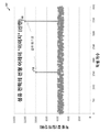
도 1b는 검출기(140)에 의해 취득되는 광 섬유의 선형 어레이 이미지를 도시하는 그래프(102).
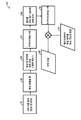
도 1c는 광 섬유(105)의 광 전력을 산출하기 위한 알고리즘(103)의 블록도.
도 2는 광 섬유(105)의 광 전력을 측정하기 위한 시스템(201)의 개략도.
도 3은 광 섬유(305)의 광 전력을 측정하기 위한 시스템(301)의 개략도.
도 4a는 본 발명의 일 실시예에 따른 선형 어레이 검출기에 의해 발생하는 이미지(401)의 개략도.
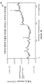
도 4b는 도 4a의 이미지(401) 중 하나에 기초하여 발생하는 섬유 전력의 선형 어레이 프로파일을 도시하는 그래프(402).
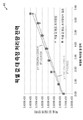
도 4c는 도 4b의 그래프(402)에 적어도 부분적으로 기초하여 결정되는 측정 출력 전력을 도시하는 그래프(403).
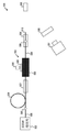
도 5a는 광 섬유의 광 전력을 측정하기 위한 시스템(501)의 개략도.
도 5b는 도 5a의 검출기(540)에 의해 발생하는 이미지(503)의 개략도.
도 5c는 광 섬유의 광 전력을 측정하기 위한 시스템(504)의 개략도.
도 6은 본 발명의 실시예들과 함께 사용되는 하드웨어 및 동작 환경(또는 운영 체제)(601)의 개요도.1A is a schematic diagram of a
1B is a
1C is a block diagram of an
2 is a schematic diagram of a
3 is a schematic diagram of a
4A is a schematic diagram of an
FIG. 4B is a
4C is a
5A is a schematic diagram of a
Figure 5b is a schematic diagram of an
5C is a schematic diagram of a
6 is a schematic diagram of a hardware and operating environment (or operating system) 601 used with embodiments of the present invention.
다음에 따르는 상세한 설명은 예시를 위해 많은 상세들을 포함하고 있지만, 통상의 기술자라면, 다음에 따르는 상세에 대한 많은 변동과 변경이 본 발명의 범위 내에 있음을 인식할 것이다. 구체적인 예들을 사용하여 구체적인 실시예들을 예시하고 있지만, 청구범위에서 설명하는 발명은, 이러한 실시예들로만 한정하려는 것이 아니라 청구범위의 전체 범위를 포함하려는 것이다. 이에 따라, 다음에 따르는 본 발명의 바람직한 실시예들은, 청구 발명에 대한 어떠한 일반성도 잃지 않고 또한 청구 발명을 한정하지 않고 개시된 것이다. 또한, 다음에 따르는 바람직한 실시예들의 상세한 설명에서는, 본원의 일부를 이루며 본 발명을 실시할 수 있는 특정한 실시예들을 예시하도록 도시된 첨부 도면을 참조한다. 본 발명의 범위로부터 벗어나지 않고 다른 실시예들을 이용할 수 있고 구조적 변화를 행할 수 있음을 이해하도록 한다. 도면에 도시하고 본원에서 설명하는 실시예들은, 모든 특정한 실시예들에 포함되지 않은 특징부들을 포함할 수 있다. 구체적인 실시예는 설명하는 모든 특징부들의 서브세트만을 포함할 수 있고, 또는, 구체적인 실시예는 설명하는 모든 특징부들을 포함할 수 있다.Although the following detailed description includes many details for illustrative purposes, those of ordinary skill in the art will recognize that many variations and modifications to the details that follow are within the scope of the invention. While specific examples are used to illustrate specific embodiments, the invention described in the claims is intended to cover the full scope of the claims, rather than being limited only to these embodiments. Accordingly, the following preferred embodiments of the present invention have been disclosed without losing any generality to the claimed invention and without limiting the claimed invention. In the following detailed description of the presently preferred embodiments, reference is made to the accompanying drawings which form a part hereof, and in which is shown by way of illustration specific embodiments in which the invention may be practiced. It is to be understood that other embodiments may be utilized and structural changes may be made without departing from the scope of the present invention. The embodiments shown in the drawings and described herein may include features not included in all specific embodiments. The specific embodiment may include only a subset of all the features described, or the specific embodiment may include all of the features described.
도면에 보이는 참조 번호의 앞 자리(들)는, 일반적으로, 도면 전체에 걸쳐 동일한 참조 번호를 사용하여 다수의 도들에 있는 동일한 구성요소를 참조하도록 그 구성요소가 처음 도입되어 있는 도면 번호에 대응한다. 신호와 접속부는, 동일한 참조 번호 또는 라벨에 참조될 수 있으며, 실제 의미는 설명의 문맥에서 사용될 때 명백할 것이다.The front position (s) of reference numerals shown in the figures generally correspond to the reference numerals in which the components are first introduced to refer to the same components in the figures using the same reference numerals throughout the drawings do. Signals and connections may be referenced to the same reference number or label, and the actual meaning will be apparent when used in the context of the description.
본원에서 사용되는 바와 같이, "삽입 손실"은 광 섬유 내의 디바이스의 삽입으로 인해 발생하는 신호 전력의 손실을 가리킨다.As used herein, "insertion loss" refers to loss of signal power resulting from insertion of a device in an optical fiber.
도 1a는 광 섬유(105)의 광 전력을 측정하기 위한 시스템(101)의 개략도이다. 일부 실시예들에서, 시스템(101)은, 광이 광 섬유(105)의 코어를 통해 전파될 때 그 코어에 의해 산란되는 광(98)의 광 전력을 측정한다(예를 들어, 일부 실시예들에서, 광(98)은 레일리 산란을 통해 산란되는 광이다). 시스템(101)은 자연적으로 발생하는 산란 광(98)을 측정하므로, 시스템(101)은, 일부 실시예들에서, 삽입 손실이 최소이거나 없도록 광 섬유(105)에 대한 물리적 변경 및/또는 접촉 없이 광 전력 측정을 제공한다. 일부 실시예들에서, 광 섬유(105)는, 코어를 둘러싸는 제1 클래딩 층 및 제1 클래딩 층을 둘러싸는 제2 클래딩 층을 포함하고, 제1 클래딩 층은 코어의 굴절률보다 낮은 굴절률을 갖고, 제2 클래딩 층은 제1 클래딩 층의 굴절률보다 낮은 굴절률을 갖는다. 일부 실시예들에서, 시스템(101)은, 이미징 광학계(120), 이차 광학계(130), 검출기(140), 및 어두운 배경(150)을 포함한다. 일부 실시예들에서, 시스템(101)은, 이미징 광학계(120), 이차 광학계(130), 검출기(140), 및 배경(150)을 포함하고 광 섬유(105)에 대하여 고정된 시스템(101)을 유지하도록 구성된 하우징(160)을 더 포함한다(일부 실시예들에서, 시스템(101)은 하우징(160) 사용 없이 광 섬유(105)에 대하여 고정된다). 일부 실시예들에서, 광 섬유(105)의 적어도 일부는, 본원에 참고로 원용되는 미국 특허출원 제14/086,744호에 개시된 바와 같은 나선형 맨드릴 조립체에 의해 고정 위치에서 유지된다. 일부 실시예들에서, 시스템(101)은, 접속부(175)를 통해 검출기(140)에 동작가능하게 결합된 프로세서/제어기(170)(예를 들어, 컴퓨터 시스템)를 포함한다. 일부 실시예들에서, 접속부(175)는 유선 접속부이다. 다른 실시예들에서, 접속부(175)는 무선 접속부이다. 일부 실시예들에서, 프로세서/제어기(170)는, 검출기(140)에 의해 검출되는 데이터를 처리하고 측정된 광 전력 값을 출력하도록 구성된다.FIG. 1A is a schematic diagram of a
일부 실시예들에서, 이미징 광학계(120)는 렌즈를 포함한다. 일부 실시예들에서, 이미징 광학계(120)는 검출기(140)에 동작가능하게 결합된 이미징 섬유를 포함한다. 일부 실시예들에서, 이차 광학계(130)는 신호 판별 및 잡음/시스템 에러 필터링을 보조한다. 이러한 일부 실시예들에서, 이차 광학계(130)는 편광 필터를 포함한다. 이러한 다른 실시예들에서, 이차 광학계(130)는 신호 광으로부터 펌프 광을 분리하도록 구성된 파장 필터를 포함한다. 이러한 다른 실시예들에서, 이차 광학계(130)는, 클래딩 광으로부터 코어 광을 구별하기 위해 로크인 검출을 이용하도록 구성된 광탄성 변조기 또는 액정 가변 지연기 디바이스 등의 변조 광학계를 포함한다. 이러한 다른 실시예들에서, 이차 광학계(130)는 검출기(140)의 범위를 연장하도록 구성되고 선형성을 연장하도록 구성된 중성 밀도 필터를 포함한다. 이러한 또 다른 실시예들에서, 이차 광학계(130)는 전술한 구성요소들 중 두 개 이상의 조합을 포함한다. 일부 실시예들에서, 섬유(105)는 산란 광(98)의 편광 정도를 최적화하도록 코어에 대하여 배향된다.In some embodiments, the imaging
일부 실시예들에서, 검출기(140)는, 단일-픽셀 측정을 바이어싱할 수 있는 결함(예를 들어, 핫스팟(106))을 거부하도록 광 섬유(105)의 길이를 가로질러 광(98)을 검출하는 선형 어레이 검출기이다. 예를 들어, 이러한 일부 실시예들에서, 검출기(140)는 Hamamatsu Photonics K.K.(www.hamamatsu.com/us/en/product/alpha/C/4119/index.html)에 의해 제공되는 바와 같은 상보적 금속-산화물-반도체(CMOS) 선형 이미지 센서이다. 일부 실시예들에서, Hamamatsu-CMOS-선형-이미지 센서 군은, 200nm 내지 1000nm 범위의 광을 검출하고, 64개 내지 4098개 픽셀의 픽셀 카운트로 가변된다. 일부 실시예들에서, 검출기(140)는 Hamamatsu Photonics K.K.(www.hamamatsu.com/us/en/product/alpha/I/4107/index.html)에 의해 제공되는 바와 같은 인듐-갈륨-비소(InGaAs) p형 진성 n형(PIN) 포토다이오드 어레이 등의 선형 어레이 검출기이다. 일부 실시예들에서, Hamamatsu InGaAs-PIN-포토다이오드-어레이 센서 군은, 700nm 내지 1700nm 범위의 광을 검출하고, 16개 내지 46개 픽셀의 픽셀 카운트로 가변된다. 일부 실시예들에서, 검출기(140)는 Edmunds Optics, Inc.(www.edmundoptics.com/imaging/cameras/usb-cameras/eo-usb-3-0-cmos-machine-vision-cameras/86-752)에 의해 제공되는 바와 같은 E0-0413M Monochrome USB 3.0 Camera 등의 머신 비전 카메라이다. 일부 실시예들에서, 검출기(140)는 2차원 어레이 검출기(본원에서 M 대 N 검출기라고도 함)이다. 일부 실시예들에서, 검출기(140)는 다른 임의의 적절한 이미징 디바이스이다(예를 들어, 일부 실시예들에서, 검출기(140)는, 감도가 관심 파장 범위 또는 관심 전력 범위에 적절한 임의의 이미징 디바이스이다). 일부 실시예들에서, 검출기(140)는, 다른 임의의 적절한 광 검출 디바이스이다(예를 들어, 일부 실시예들에서, 검출기(140)는, 감도가 관심 파장 범위 또는 관심 전력 범위에 적절한 임의의 검출기이다.In some embodiments, the
일부 실시예들에서, 검출기(140)에 의해 취득되는 이미징 및/또는 광 검출 데이터는, 단위 길이당 산란을 핫스팟(106), 클래딩, 버퍼, 또는 다른 비균일 결함으로부터 판별하도록 강도 대 위치 데이터로 동작하는 알고리즘에서 사용된다. 일부 실시예들에서, 핫스팟 또는 스파이크(106)는, 평균을 산출하기 전에 또는 전력 캘리브레이션 룩업 테이블에 이후에 매핑되는 기능성 맞춤 또는 전력 결정에 대한 기타 기능적 매핑을 수행하기 전에 제거된다.In some embodiments, the imaging and / or photodetection data acquired by the
일부 실시예들에서, 시스템(101)은, 레이저 손상을 야기하지 않고 고 전력 범위(예를 들어, 일부 실시예들에서, 적어도 1kW)의 광 섬유의 광 전력을 측정하는 데 적절하다. 일부 실시예들에서, 시스템(101)은 삽입 손실을 도입하지 않고 광 전력 측정을 제공한다. 일부 실시예들에서, 시스템(101)은, 레이저 손상을 방지하도록 섬유(105)와의 물리적 접촉 없이(또는 적어도 측정되는 광 섬유(105)의 일부와의 물리적 접촉 없이) 광 전력 측정을 제공한다. 일부 실시예들에서, 시스템(101)은 안전성 인터로크 또는 페일세이프(failsafe) 셧다운을 용이하게 하도록 전력 변화 검출을 제공한다. 일부 실시예들에서, 시스템(101)은 다양한 폐쇄 루프 전력 응답 동작(예를 들어, 폐쇄 루프 정전력 유지)을 용이하게 한다. 일부 실시예들에서, 시스템(101)은 광 섬유(105)에 대한 스플라이싱을 필요로 하지 않는다. 일부 실시예들에서, 시스템(101)은 시스템 구성을 최적화하도록 이동가능하다. 일부 실시예들에서, 시스템(101)은, 사용자가 그 시스템을 진단 기구 또는 공장 출하시 설정된 기구로서 사용하는 데에만 관심을 갖는다면, 탈착가능하다. 일부 실시예들에서, 시스템(101)은 동작 동안 전력을 감시하도록 제 위치에서 유지된다. 일부 실시예들에서, 시스템(101)은 섬유 군을 위한 전력 캘리브레이션을 제공한다.In some embodiments, the
도 1b는 검출기(140)에 의해 취득되는 섬유 전력의 선형 어레이 이미지의 그래프(102)이다. 일부 실시예들에서, 검출기(140)에 의해 취득되는 선형 어레이 데이터는, 군을 벗어난 핫스팟 또는 어두운 드롭아웃(예를 들어, 핫스팟(160))의 거부를 포함한 여러 수단에 의한 분석을 제공한다. 일부 실시예들에서, 그래프(102)는 프로세서/제어기(170)에 의해 제공된다.1B is a
도 1c는 광 섬유(105)의 광 전력을 산출하기 위한 알고리즘(103)의 블록도이다. 일부 실시예들에서, 알고리즘(103)은, 최종 전력 산출로부터 바이어스를 제거하도록 도 1b의 강도 대 위치 데이터에서 "스파이크"로서 보이는 핫스팟(106)이 필터링될 수 있게 한다. 일부 실시예들에서, 알고리즘(103)은, 선형 또는 2차원 어레이 검출기(예를 들어, 검출기(140)에 대하여 설명한 바와 같은 선형 어레이 검출기)의 포함 때문에 수행될 수 있다. 일부 실시예들에서는, 단일 픽셀 검출기가 핫스팟(106)에 의해 오동작할 수 있기 때문에 알고리즘(103)을 갖는 선형 어레이 검출기를 사용하여 전력을 측정함으로써, 단일 픽셀 검출기(예를 들어, 도 2의 검출기(240))의 전력 측정을 개선한다.1C is a block diagram of an
일부 실시예들에서, 블록 191에서, 검출기(예를 들어, 도 1a의 검출기(140))는, 광 섬유(105)의 길이의 이미지를 캡처한다(예를 들어, 일부 실시예들에서, 캡처된 이미지는 광 섬유(105)의 길이를 따른 강도 대 위치를 나타낸다). 일부 실시예들에서, 검출기(140)는, 캡처된 이미지에 관한 데이터를 프로세서(예를 들어, 도 1a의 프로세서/제어기(170) 또는 도 6의 시스템(601))에 송신하고, 이 프로세서는 블록 192 내지 198을 수행한다. 일부 실시예들에서는, 블록 192에서, 이미지 데이터의 배경 레벨을 뺀다. 일부 실시예들에서, 이어서, 블록 193에서, 블록 192에 의해 출력되는 데이터는 ("플랫 필드"라고도 알려져 있는) 응답 대 위치에 의해 분할된다. 일부 실시예들에서, 블록 194에서는, 블록 193에 의해 출력되는 데이터에 대하여 푸리에 변환을 수행하고 블록 195에서는, 블록 194로부터의 결과를 로우 패스 필터에 의해 승산한다. 일부 실시예들에서, 블록 196에서는, 블록 195에 의해 출력되는 데이터에 대하여 역 푸리에 변환을 수행한다. 일부 실시예들에서, 블록 196의 출력은 기능성 맞춤 또는 캘리브레이션 룩업 테이블로부터의 정보와 결합된다(예를 들어, 블록 198의 산출된 전력을 발생시키는 블록 197을 참조한다). 일부 실시예들에서, 블록 194의 푸리에 변환과 블록 195의 로우 패스 필터는, 핫스팟의 영향을 감소시키도록 임의의 픽셀에서의 값을 해당 픽셀 자체와 이웃하는 픽셀들 일부 양의 평균으로 교체하는 평활화 연산에 의해 교체된다. 일부 실시예들에서, 블록 194의 푸리에 변환과 블록 195의 로우 패스 필터는, "핫스팟" 아웃라이어 데이터를 폐기하도록 소정의 임계값보다 높은 픽셀 값들을 폐기하는 통계적 거부에 의해 교체된다.In some embodiments, at block 191, a detector (e.g.,
도 2는 광 섬유(105)의 광 전력을 측정하기 위한 시스템(201)의 개략도이다. 일부 실시예들에서, 시스템(201)은, 시스템(201)이 단일-픽셀 검출기(240)를 포함한다는 점을 제외하고는 시스템(101)과 실질적으로 유사하다. 예를 들어, 시스템(201)의 일부 실시예들에서, 검출기(240)는 Thorlabs Inc.에 의해 제공되는 바와 같은 인듐-갈륨-비소(InGaAs) 포토다이오드이다(www.thorlabs.com/thorproduct.cfm?partnumber=FDGA05). 이러한 일부 실시예들에서, 검출기(240)는, 변경 검출기 또는 고장 셧다운 검출기로서의 역할을 수행할 정도로 빠르다. 시스템(201)의 일부 실시예들에서, 이차 광학계(120)는 파장 필터를 포함한다. 일부 실시예들에서, 시스템(201)은 상대 전력 또는 고장 검출을 위한 전력 측정을 제공한다. 일부 실시예들에서, 시스템(201)은 저가이며, 섬유(105)의 임의의 위치에 "끼워진다". 일부 실시예들에서, 시스템(201)은 도 3에 개시한 바와 같은 로크인 검출 및 편광 변조와 조합하여 사용된다.2 is a schematic diagram of a
도 3은 광 섬유(305)의 광 전력을 측정하기 위한 시스템(301)의 개략도이다. 일부 실시예들에서, 광 섬유(305)는 편광 유지(PM) 섬유(예를 들어, "팬더" 스타일 섬유)이며, 코어 전파 광 신호의 전계 방향을 나타내는 알려져 있는 편광 배향(308)(예를 들어, 느린-축 정렬 편광)을 갖는다. 일부 실시예들에서, 섬유(305)는, 섬유 코어(306), 및 "팬더" 스타일 PM 섬유 응력 부재(307)를 포함한다. 일부 실시예들에서, 레일리 산란의 동작으로 인해, 섬유 전파 방향과 편광 전계 방향 모두에 수직인 방향으로 산란되는 광자들(즉, 산란 광(98))은 편광의 정도와 강도에 있어서 더욱 높다. 따라서, 일부 실시예들에서, 코어 산란 광자들은, 산란 광(98)을 분석 및/또는 변조함으로써 배경 레벨들로부터 구별된다. 일부 실시예들에서, 레일리 산란의 동작으로 인해, 편광 전계에 평행한 방향으로 산란되는 광자들(즉, 산란 광(97))은, 적으며, 편광 정도가 낮다. 일부 실시예들에서, 시스템(301)의 광학 구성요소들은, 편광 배향(308)에 기초하여, 산란 광(98)에 연관된 대량의 레일리 산란과 고 정도의 편광의 이점을 취하도록 배열된다. 일부 실시예들에서, 시스템(301)은, 삽인 손실이 최소이거나 없도록 광 섬유(305)의 물리적 변경 및/또는 접촉 없이 광 전력 측정을 제공한다. 일부 실시예들에서, 시스템(301)은 섬유 군에 대한 전력 캘리브레이션을 제공한다.3 is a schematic diagram of a
일부 실시예들에서, 시스템(301)은, 콜리메이팅 광학계(310) 및 이미징 광학계(320)를 포함한다(예를 들어, 일부 실시예들에서, 콜리메이팅 렌즈(310) 및 이미징 렌즈(320)). 일부 실시예들에서, 콜리메이팅 광학계(310)와 이미징 광학계(320) 사이의 공간이 콜리메이팅 공간(317)이며, 이는, 예를 들어, 파장 필터, 중성 밀도 필터, 편광 변조기(예를 들어, 편광 변조기(315)), 편광 필터(예를 들어, 편광기(316)) 및/또는 기타를 포함하는 단일 또는 복합 광 조립체를 배치하는 데 적절한 영역이다.In some embodiments,
일부 실시예들에서, 편광 변조기(315)는 액정(LC) 변조기를 포함한다. 일부 실시예들에서, 편광 변조기(315)는 광탄성 변조기(PEM)를 포함한다. 일부 실시예들에서, 편광 변조기(315)는 다른 임의의 적절한 편광 변조기이다. 일부 실시예들에서, 편광기(316)는 능동 편광기이다. 다른 실시예들에서, 편광기(316)는 수동 편광기이다. 일부 실시예들에서, 편광 변조기(315)와 편광기(316)는 광(98)의 편광 또는 강도 진폭을 수정하도록 구성된다. 일부 실시예들에서, 프로세서/제어기(370)에 의해 제공되는 로크인 검출 알고리즘과 함께 변조기(315)와 편광기(316)에 의해 제공되는 편광 변조는, 광(98)의 코어 광을 더욱 크게 구별할 수 있도록 광(98)의 신호대 잡음비를 개선하는 데 일조한다(예를 들어, 일부 실시예들에서, 프로세서/제어기(370)는 로크인 증폭기를 포함한다).In some embodiments, the
일부 실시예들에서, 시스템(301)은 이차 광학계(330)(예를 들어, 일부 실시예들에서, 파장 필터) 및 검출기(340)를 더 포함한다. 일부 실시예들에서, 이미징 광학계(320)는 광(98)을 검출기(340) 상에 이미징한다. 일부 실시예들에서, 검출기(340)는 섬유(305)의 길이를 따라 정렬되는 선형 어레이 검출기를 포함한다. 일부 실시예들에서, 검출기(340)는 2차원 어레이 검출기이다. 일부 실시예들에서, 검출기(340)는 단일 픽셀 검출기이다. 일부 실시예들에서, 검출기(340)는 카메라이다. 일부 실시예들에서, 검출기(340)는 고 대역폭(BW) 검출기이다. 일부 실시예들에서, 검출기(340)는 다른 임의의 적절한 광 검출 디바이스이다. 일부 실시예들에서, 검출기(340)는 접속부(375)를 통해 프로세서/제어기(370)에 동작가능하게 결합되고, 프로세서/제어기(370)는 또한 접속부(376)를 통해 편광 변조기(315)에 동작가능하게 결합된다. 일부 실시예들에서, 접속부(375, 376)는 유선 접속부이다. 일부 실시예들에서, 접속부(375, 376)는 무선 접속부이다. 일부 실시예들에서, 접속부(375, 376) 중 하나는 유선 접속부이고 나머지 하나는 무선 접속부이다.In some embodiments, the
도 4a는 이미징 카메라에 의해 발생하는 이미지(401)의 개략도이다. 일부 실시예들에서, 각 이미지(401)는 광 섬유의 동일한 길이를 따라 서로 다른 시간에 검출되는 서로 다른 광 전력을 나타낸다(예를 들어, 일부 실시예들에서, 각 이미지(401)는 도 1a의 시스템(101)을 이용하여 발생하지만, 광 신호는 각 이미지마다 서로 다른 전력 값으로 설정된다).4A is a schematic view of an
도 4b는 도 4a의 이미지(401) 중 하나에 기초하여 발생하는 섬유 전력의 선형 어레이 프로파일을 도시하는 그래프(402)이다. 일부 실시예들에서, 본 발명은, 광 섬유의 길이를 따른 선형 어레이 프로파일의 국부적 불연속성을 식별하고 거부하는 (예를 들어, 도 1a의 프로세서/제어기(170)에 의해 또는 도 6의 시스템(601)에 의해 실행되는) 소프트웨어를 제공한다(예를 들어, 일부 실시예들에서, 그래프(402)는 출력 전력의 산출시 거부될 선형 어레이 프로파일의 피크를 식별한다).FIG. 4B is a
도 4c는, 도 4b의 그래프(402)에 적어도 부분적으로 기초하여 결정되는 측정 출력 전력을 도시하는 그래프(403)이다. 일부 실시예들에서, 그래프(403)는, 측정 출력 전력과 본 발명의 어레이 검출기에 의해 검출되는 값들 간에 기능성 맞춤(예를 들어, 선형 맞춤)이 어떻게 행해지는지를 나타낸다. 일부 실시예들에서, 이러한 선형 맞춤은, 도 4b의 그래프(402)에서 식별되는 피크들 등의 원시 데이터로부터 핫스팟을 거부하거나 트리밍함으로써 개선된다. 일부 실시예들에서, 그래프(402)와 그래프(403)에 사용되는 데이터는, 본 발명의 전력 측정에 연관된 선형성과 캘리브레이션을 입증한 도 1a의 시스템(101)을 이용한 비접촉 이미징 실험에 기초하였다. 일부 실시예들에서는, 그래프(403)에 도시한 캘리브레이션을 위해 단조 거동만이 필요하다.4C is a
도 5a는 광 섬유의 광 전력을 측정하는 시스템(501)의 개략도이다. 일부 실시예들에서, 시스템(501)은 광 신호 발생기(502)를 포함한다(일부 실시예들에서, 발생기(502)는 300W 레이저이다). 일부 실시예들에서, 광 신호 발생기(502)는, 5A is a schematic diagram of a
20마이크로미터 직경(20㎛)의 코어와 400마이크로미터 직경(400㎛)의 외부 클래딩을 갖는 수동 더블 클래드 광 섬유(505)(본원에서 20/400 광 섬유라고도 함)에 결합된다. 일부 실시예들에서, 수동 섬유(505)는 스플라이스(595)에서 5미터 길이의 이득 섬유(506)로 스플라이싱된다. 일부 실시예들에서, 이득 섬유(506)는 nLight, Leiki, Nufern, CorActive 등에 의해 제공되는 것 등의 더블 클래드 PLMA-YDF(polarization-maintaining-large-mode-area ytterbium-doped-fiber) 20/400 광 섬유이다. 일부 실시예들에서, 이득 섬유(506)는 펌프 덤프(507)에 결합된다(예를 들어, 일부 실시예들에서, 펌프 덤프(507)는 스트립핑된 이득 섬유 및/또는 인덱스 일치 유체 또는 접착제를 포함한다). 일부 실시예들에서, 펌프 덤프(507)는 펌프 덤프(507)와 제2 펌프 덤프(509) 사이에서 이어지는 도핑된 이득 섬유(508)에 결합된다. 일부 실시예들에서, 이득 섬유(508)는 약 1m(3.28feet) 길이를 갖는다.(Also referred to herein as 20/400 optical fibers) having a core of 20 micrometers in diameter (20 micrometers) and an outer cladding of 400 micrometers in diameter (400 micrometers). In some embodiments, the
일부 실시예들에서, 시스템(501)은, 이득 섬유(508)에 결합되고 이득 섬유(508)를 통해 전파되는 광 신호의 전력을 검출하도록 구성된 전력 검출 모듈(580)을 더 포함한다. 일부 실시예들에서, 전력 검출 모듈(580)은, 신호 광으로부터 펌프 광을 분리하도록 구성된 파장 필터(520), 흑색 배경(550), 및 섬유(508) 코어로부터 산란되는 광을 검출하거나 이미징하도록 구성된 검출기(540)를 포함한다. 일부 실시예들에서, 검출기(540)는 도 1a의 검출기(140)에 대하여 전술한 바와 같은 검출기 또는 카메라이다. 일부 실시예들에서, 섬유(508)는 스플라이스(596)에서 수동 싱글 클래드 20/400 전달 섬유(510)에 스플라이싱된다. 일부 실시예들에서, 전달 섬유(510)는 전력 검출 모듈(580)의 캘리브레이션을 제공하도록 구성된 캘리브레이션 출력계(585)에 결합된다(이러한 일부 실시예들에서, 전력 미터(585)는 Ophir Optronics Solutions Ltd.에 의한 Ophir PD300-IRG Fiber Optic Power Meter Head이다)(www.ophiropt.com/laser-measurement-instruments/new-products/pd300-r). 이러한 일부 실시예들에서, 미터(585)를 펌프 덤프들(507, 509)의 하류측에 배치함으로써, 모듈(580)에 의해 발생하는 전력 검출 데이터를 분석할 때 신호 광으로부터 클래딩 펌프 광을 빼는 것을 보장한다. 일부 실시예들에서, 시스템(501)은, 모듈(580)에 의해 발생하는 데이터의 신호대 잡음비를 더욱 개선하도록 (예를 들어, 도 3의 시스템(301)에 의해 제공되는 바와 같은) 편광 변조 및 로크인 검출을 더 포함한다.The
도 5b는 도 5a의 검출기(540)에 의해 발생하는 이미지(503)의 개략도이다. 일부 실시예들에서, 각 이미지(503)는 섬유(508)의 동일한 길이를 따라 서로 다른 시간에 검출되는 서로 다른 광 전력을 나타낸다. 일부 실시예들에서, 이미지(503)에 의해 예시되는 고 전력 이미징은, 도 5a의 시스템(501)에 의해 제공되는 바와 같은 적절한 이득 및 감쇠 필터 선택에 의해 축소확대가능하다.FIG. 5B is a schematic diagram of an
도 5c는 광 섬유의 광 전력을 측정하는 시스템(504)의 개략도이다. 일부 실시예들에서, 시스템(504)은, 전력 미터(585)와 전달 섬유(510)의 단부 사이에 자유 공간이 있도록 전달 섬유(510)가 클리브 또는 연마된다는 점을 제외하고는 도 5a의 시스템(501)과 실질적으로 유사하다. 이러한 일부 실시예들에서, 시스템(504)은, 광 빔이 전력 미터(585)와 충돌할 때 섬유(510)로부터 출력되는 광 빔을 이미징하도록 구성된 카메라(531)를 더 포함한다. 일부 실시예들에서, 광 감쇠기(530)(예를 들어, 중성 밀도 필터, 부분 반사 미러, 스모킹 글래스 등)를 사용하여 카메라(531)에서의 광 전력 레벨을 제어한다. 일부 실시예들에서, 카메라(531)에 의해 제공되는 이미징을 이용하여 광 빔을 전력 미터(585) 상의 중심에 오도록 맞춘다.5C is a schematic diagram of a
일부 실시예들에서, 시스템(504)은, 또한, 시스템(580)을 캘리브레이션하는 데 사용된다(예를 들어, 일부 실시예들에서, 시스템(504)은 전력 미터(585)에서 실제 전력 대 시스템(580) 응답의 룩업 테이블을 생성하는 데 사용된다). 일부 실시예들에서, 전력 미터(585)는, 일반적으로 수용되는 광 전력과 파장 표준으로 추적가능하게 캘리브레이션된다(예를 들어, NIST(National Institute of Standards and Technology) 추적가능 캘리브레이션). 일부 실시예들에서, 검출기(540)는, 도 1a의 일부 실시예들에 대하여 설명하고 도시한 바와 같은 선형 어레이 검출기이다(이러한 일부 실시예들에서, 검출기(540)는 전술한 Hamamatsu Photonics K.K.에 의해 제공되는 CMOS 선형 이미지 센서이다). 일부 실시예들에서, 카메라(531)는 검출기(540)의 복제 모델이다. 이러한 일부 실시예들에서, 전력 미터(585)에서의 전력 판독은, 카메라(531)와 이에 따른 의도한 시스템(58)의 응용분야에 대하여 전력 범위에 걸쳐 유용한 충분한 동적 범위를 검출기(540)가 갖고 있음을 확인하는 데 사용된다. 일부 실시예들에서, 전력 미터(588) 상에 광 빔을 이미징함으로써 카메라(531)에 의해 발생하는 픽셀 카운트를 사용하여, 카메라(531)가 충분한 광 전력 범위에 걸쳐 단조 응답을 갖는지 여부를 결정한다(예를 들어, 픽셀 카운트는, 광 전력 값이 증가할 때 결코 감소하지 않는다.In some embodiments, the
도 6은 본 발명의 실시예들과 함께 사용되는 하드웨어 및 동작 환경(또는 시스템)(601)의 개요도이다. 도 6의 설명은, 본 발명이 함께 구현될 수 있는 적절한 컴퓨터 하드웨어와 적절한 연산 환경의 간략하고 일반적인 설명을 제공하고자 하는 것이다. 일부 실시예들에서, 본 발명은, 컴퓨터 판독가능 매체에 저장되며 도 1a의 프로세서/제어기(170) 등의 제어기에 상주하는 마이크로프로세서 등의 시스템(601)에 의해 실행되는 프로그램 모듈 등의 컴퓨터 실행가능 명령어의 일반적인 문맥으로 설명된다(예를 들어, 일부 실시예들에서, 이러한 명령어는, USB FLASH 드라이브, 플로피 디스크, CDROM, 인터넷에 접속된 저장 장치 등의 비일시적 저장 매체에 저장되며, 본 발명의 일부 실시예들에서 사용되는 방법을 수행하도록 사용된다). 일반적으로, 프로그램 모듈은, 구체적인 태스크를 수행하거나 구체적인 추상 데이터 유형을 구현하는 루틴, 프로그램, 오브젝트, 컴포넌트, 데이터 구조 등을 포함한다.FIG. 6 is a schematic diagram of a hardware and operating environment (or system) 601 for use with embodiments of the invention. The description of FIG. 6 is intended to provide a brief, general description of the appropriate computing hardware and the appropriate computing environment in which the invention may be implemented. In some embodiments, the present invention may be embodied in a computer readable medium, such as a program module, stored on a computer readable medium and executed by a
또한, 통상의 기술자는, 핸드헬드 디바이스, 멀티프로세서 시스템, 마이크로프로세서 기반 또는 프로그래밍가능 소비자 전자 장치, 네트워크 퍼스널 컴퓨터(네트워크 PC), 미니컴퓨터, 메인프레임 컴퓨터 등을 포함하는 다른 컴퓨터 시스템 구성으로 본 발명을 실시할 수 있음을 인식할 것이다. 또한, 본 발명은, 태스크들이 통신 네트워크를 통해 링크되어 있는 입력-출력 원격 처리 디바이스들에 의해 수행되는 분산형 컴퓨터 환경에서 실시될 수 있다. 분산형 연산 환경에서, 프로그램 모듈들은 국부적 및 워격 메모리 저장 디바이스들 모두에 위치할 수 있다.It will also be understood by those of ordinary skill in the art that other computer system configurations, including handheld devices, multiprocessor systems, microprocessor-based or programmable consumer electronics, network personal computers (network PCs), minicomputers, mainframe computers, As will be appreciated by those skilled in the art. The invention may also be practiced in distributed computing environments where tasks are performed by input-output remote processing devices that are linked through a communications network. In a distributed computing environment, program modules may be located in both local and remote memory storage devices.
일부 실시예들에서, 시스템(601)은, 전력 미터 구성요소(680)로부터의 감지 및/또는 전력 미터 구성요소의 무선 제어(즉, 원격 마이크로프로세서의 리프로그래밍, 및 전력 미터 구성요소(680)로부터의 감지 신호와 진단 정보의 수신)를 가능하게 하는 무선(또는 유선, 광 섬유, 또는 기타 직접 접속) 송수신기(71)를 구비하고 프로그래밍가능한 사용자 제어 콘솔 컴퓨터(20)를 포함한다(예를 들어, 일부 실시예들에서, 구성요소(68)는 도 3의 편광 변조기(315)와 검출기(340)를 포함한다).In some embodiments, the
일부 실시예들에서, 하드웨어 및 동작 환경(601)은, 도 1a, 도 2, 도 3, 도 5a, 도 5c의 시스템(101), 시스템(201), 시스템(301), 시스템(501), 및/또는 시스템(504), 및/또는 전체적으로, 도 1a, 도 2, 도 3, 도 5a, 및/또는 도 5c에 도시한 개별적인 구성요소들 중 임의의 것에 각각 적용가능하다. 일부 실시예들에서, 컴퓨터 판독가능 저장 디바이스(예를 들어, 광 디스크(31)(CDROM, DVD, Blu-ray Disc™ (BD), 자기 또는 플래시 저장 디바이스(29)(예를 들어, 플로피 디스크, 섬 드라이브, SDHC™ (Secure-Data High-Capacity) 메모리 카드 등), 및/또는 원격 컴퓨터(49)에 접속된 저장 디바이스(50)(예를 들어, 일부 실시예들에서, 인터넷 등의 WAN(52) 또는 LAN(51)에 걸쳐 컴퓨터(20)에 접속되는 도 3의 고객 디바이스(320))에 저장된 애플리케이션 프로그램(36)은, 본원에서 설명되는 본 발명의 방법들에 의해 해당 동작을 제어하도록 처리되고 및/또는 구성요소들(680)에 송신되는 (룩업 테이블, 제어 파라미터, 데이터베이스 등의) 명령어 및/또는 제어 명령어를 포함한다. 일부 실시예들에서, 애플리케이션 프로그램들(36)은 컴퓨터(20)에서 부분적으로 실행된다.In some embodiments, the hardware and
도 6에 도시한 바와 같이, 일부 실시예들에서, 하드웨어 및 동작 환경은 사용자 제어 콘솔 컴퓨터(20)를 포함하고, 또는, 서버(20)는, 처리 유닛(21), 시스템 메모리(22), 및 시스템 메모리(22)를 포함하는 다양한 시스템 구성요소들을 처리 유닛(21)에 동작가능하게 결합하는 시스템 버스(23)를 포함한다. 일부 실시예들에서는, 하나의 처리 유닛만이 있을 수 있으며, 또는 다른 실시예들에서는, 하나보다 많은 처리 유닛(21)이 있을 수 있으며, 이때, 컴퓨터(20)의 프로세서는 단일 중앙 처리 유닛(CPU), 또는 흔히 멀티 프로세서 또는 병렬 처리 환경이라 칭하는 복수의 처리 유닛을 포함한다. 다양한 실시예들에서, 컴퓨터(20)는, 종래의 컴퓨터, 분산형 컴퓨터, 또는 셀폰, 개인용 정보 단말기 디바이스 또는 다른 폼 팩터에 포함된 다른 임의의 유형의 컴퓨터를 사용하여 구현될 수 있다. 예를 들어, 일부 실시예들에서, 컴퓨터(20)는, 데스크톱 컴퓨터 또는 이러한 컴퓨터들의 네트워크, 랩탑 컴퓨터(예를 들어, Macbook?), 태블릿 컴퓨터(예를 들어, iPad?), 음악 및/또는 비디오 플레이어 컴퓨터(예를 들어, iPod Touch?), 셀폰 컴퓨터(예를 들어, iPhone?), 스마트 텔레비전(인터넷으로부터 비디오 프로그래밍을 스트리밍할 수 있는 것), 인터넷으로부터 콘텐츠를 취득하여 종래의 고해상도 TV에 출력하는 비디오 스트리밍 디바이스(예를 들어, Roku? 또는 AppleTV?), 자동차 또는 기타 차량의 컴퓨터/MP3-플레이어/CD-플레이어/GPS/폰 시스템, 또는 다른 임의의 적절한 퍼스널 연산(PC) 플랫폼 등의 임의의 적절한 연산 디바이스로서 구현된다(여러 개의 Apple? 제품들이 본원에서 통상적인 예들로서 열거되어 있지만, 대부분의 통상의 기술자들은 이러한 Apple? 제품들에 대한 유사점에 의해 디바이스의 유형을 식별할 수 있으므로, 다른 임의의 제조사의 제품들을 대체할 수 있다).6, the hardware and operating environment includes a user
시스템 버스(23)는, 다양한 버스 아키텍처들 중 임의의 것을 이용하는 메모리 버스 또는 메모리 제어기, 주변 버스, 및 로컬 버스를 포함하는 버스 구조의 여러 유형들 중 임의의 것일 수 있다. 또한, 시스템 메모리는, 간단히 메모리라 칭할 수 있고, ROM(24)과 RAM(25)을 포함한다. 예를 들어 기동 동안 컴퓨터(또는 서버)(20) 내의 소자들 간의 정보 전달에 일조하는 기본 루틴을 포함하는 기본 입력/출력 시스템(BIOS; 26)이 ROM(24)에 저장될 수 있다. 컴퓨터(20)는, 자기 하드 디스크에 대하여 판독과 기입을 행하기 위한 하드 디스크 드라이브(27), 탈착가능 자기 플로피 디스크 또는 플래시 저장 디바이스(29)에 대하여 판독과 기입을 행하기 위한 탈착가능 매체 드라이브 또는 플래시 제어기(28), 및 (CDROM, DVD, Blu-ray Disc™(BD), 또는 기타 광 매체 등의) 탈착가능 광 디스크(31)에 대하여 판독과 기입을 행하기 위한 광 디스크 드라이브(30)를 더 포함한다.The
하드 디스크 드라이브(27), 자기 디스크 드라이브(28), 및 광 디스크 드라이브(30)는, 하드 디스크 드라이브 인터페이스(32), 자기 디스크 드라이브(33), 및 광 디스크 드라이브 인터페이스(34)에 각각 결합된다. 드라이브 및 이들의 연관된 컴퓨터 판독가능 매체는, 컴퓨터(20)를 위한 컴퓨터 판독가능 명령어, 데이터 구조, 프로그램 모듈, 및 기타 데이터의 비휘발성 비일시성 저장 장치를 제공한다. 통상의 기술자라면, 자기 카세트, 플래시 메모리 카드, 디지털 비디오 디스크, 베르누이 카트리지, RAM, ROM, 독립 디스크들의 리던던트 어레이(예를 들어, RAID 저장 디바이스) 등의 컴퓨터에 의해 액세스가능한 데이터를 저장할 수 있는 임의의 유형의 컴퓨터 판독가능 매체가 예시적인 동작 환경에서 사용될 수 있음을 인식해야 한다.The
본 발명의 방법들(예를 들어, 측정된 처리량 전력에 대한 어레이 검출기 픽셀 값들의 룩업 테이블 또는 기능성 맞춤)을 구현하는 복수의 프로그램 모듈은, 운영 체제(35), 하나 이상의 애플리케이션 프로그램(36), 기타 프로그램 모듈(37), 및 프로그램 데이터(38)를 포함하는, 하드 디스크, 자기 또는 플래시 저장 디바이스(29), 광 디스크(31), ROM(24), 또는 RAM(25)에 저장될 수 있다. 본 발명을 위한 보안 송신 엔진을 포함하는 플러그인 프로그램은 임의의 하나의 컴퓨터 판독가능 매체 상에 또는 복수의 이러한 컴퓨터 판독가능 매체 상에 상주할 수 있다.A plurality of program modules that implement the methods of the present invention (e.g., a lookup table or functional fit of array detector pixel values for measured throughput power) may include an
일부 실시예들에서, 사용자는, 키보드(40), 포인팅 디바이스(42) 또는 기타 적절한 디바이스 등의 입력 디바이스들을 통해 컴퓨터(20)에 커맨드를 입력한다. 이러한 입력 디바이스들은, 시스템 버스(23)에 결합된 직렬 포트 인터페이스(46)를 통해 처리 유닛(21)에 종종 접속되지만, 병렬 포트, 게임 포트, 또는 유니버설 시리얼 버스(USB) 등의 다른 인터페이스에 의해 접속될 수 있고, 모니터(47) 또는 다른 유형의 디스플레이 디바이스도 비디오 어댑터(48) 등의 인터페이스를 통해 시스템 버스(23)에 접속될 수 있다. 모니터(47)는 청각학자 및/또는 사용자를 위한 그래픽 유저 인터페이스를 표시할 수 있다. 모니터(47)에 더하여, 컴퓨터는, 통상적으로, 스피커와 프린터 등의 다른 주변 출력 디바이스(도시하지 않음)를 포함한다.In some embodiments, a user enters commands into the
일부 실시예들에서, 컴퓨터(20)는, 원격 컴퓨터(49) 등의 하나 이상의 원격 컴퓨터 또는 서버에 대한 논리적 접속부를 이용하여 네트워크화 환경에서 동작한다. 이러한 논리적 접속부는, 컴퓨터(20)에 또는 컴퓨터(20)의 일부에 결합된 통신 디바이스에 의해 달성되고, 본 발명은 통신 디바이스의 구체적인 유형으로 한정되지 않는다. 원격 컴퓨터(49)는, 다른 컴퓨터, 서버, 라우터, 네트워크 PC, 클라이언트, 피어 디바이스, 또는 기타 공통 네트워크 노드일 수 있고, 통상적으로, 컴퓨터(20)에 관하여 전술한 요소들 중 상당수 또는 모두를 포함하지만, 메모리 저장 디바이스(50)와 애플리케이션 프로그램(36)만이 도 6에 도시되어 있다. 도 4에 도시한 논리적 접속부는 LAN(51) 및 WAN(52)을 포함한다. 이러한 네트워킹 환경은, 네트워크의 모든 형태인, 오피스 네트워크, 기업형 컴퓨터 네트워크, 인트라넷 및 인터넷에서 흔하다.In some embodiments, the
컴퓨터(20)는, LAN 환경에서 사용되는 경우, 통신 디바이스의 한 유형인, 네트워크 인터페이스, 모뎀, 또는 어댑터(53)를 통해 LAN(51)에 접속된다. 컴퓨터(20)는, 인터넷 등의 WAN 환경에서 사용되는 경우, 통상적으로, 어댑터 또는 모뎀(54)(통신 디바이스의 한 유형), 또는 다른 임의의 유형의 통신 디바이스, 예를 들어, 인터넷 등의 WAN(52)에 대하여 통신을 확립하기 위한 무선 송수신기를 포함한다. 내장형 또는 외장형일 수 있는 모뎀(54)은 직렬 포트 인터페이스(46)를 통해 시스템 버스(23)에 접속된다. 네트워크화 환경에서, 퍼스널 컴퓨터(20) 또는 그 일부에 대하여 설명되는 프로그램 모듈들은, 원격 컴퓨터(또는 서버)(49)의 원격 메모리 저장 디바이스(50)에 저장될 수 있고, 인터넷을 통해 또는 기타 통신 수단을 통해 액세스될 수 있다. 인터넷 상의 일시적 신호는 저장되어 있는 프로그램 코드를 하나 이상의 네트워크 상의 그 신호에 의해 한 위치에서의 비일시적 저장 매체로부터 다른 위치에서의 그 프로그램 코드를 실행하는 컴퓨터로 이동시킬 수 있다는 점에 주목한다. 네트워크 또는 인터넷으로부터 취득되는 프로그램 명령어와 데이터 구조는, 네트워크 자체에 "저장"되지 않지만, 액세스를 위해 인터넷에 때때로 접속될 수 있는 비일시적 저장 매체에 저장된다. 도시한 네트워크 접속부는 예시적인 것이며, 일부 실시예들에서는, 공지되어 있으며 통상의 기술자가 이해하듯이, 하이브리드 섬유-동축 접속부, T1-T3 라인, DSL's, OC-3 및/또는 OC-12, TCP/IP, 마이크로파, WAP(무선 애플리케이션 프로토콜), 및 표준 스위치, 라우터, 아웃렛, 전력 라인을 통한 다른 모든 전자 매체를 포함하는, 컴퓨터들 간의 통신 링크를 확립하기 위한 통신 디바이스 및 그 통신 링크를 확립하기 위한 기타 수단을 사용할 수 있다는 점을 이해할 수 있다.The
본 발명의 실시예들을 함께 실시할 수 있는 하드웨어 및 동작 환경을 설명하였다. 본 발명의 실시예들을 함께 실시할 수 있는 컴퓨터(20)는, 종래의 컴퓨터, 분산형 컴퓨터, 또는 다른 임의의 유형의 컴퓨터일 수 있고, 본 발명은 이에 한정되지 않는다. 이러한 컴퓨터(20)는, 통상적으로, 자신의 프로세서로서 하나 이상의 처리 유닛, 및 메모리 등의 컴퓨터 판독가능 매체를 포함한다. 또한, 컴퓨터(20)는, 네트워크 어댑터 또는 모뎀 등의 통신 디바이스를 포함할 수 있고, 따라서, 다른 컴퓨터, 서버, 또는 디바이스에 통신가능하게 결합될 수 있다. 일부 실시예들에서, 시스템(601)의 하나 이상의 구성요소들은 사용자로부터 입력을 유도 및 수신하고, 그 입력에 기초하여, 본원에서 설명하는 바와 같은 본 발명의 방법들 중 하나 이상을 수정, 조정, 또는 실행한다.The hardware and operating environment in which embodiments of the present invention can be practiced together have been described. The
일부 실시예들에서, 본 발명은 도 5c에 도시한 바와 같은 인터럽트 전력 측정 시스템을 위한 클리브 섬유 론치(cleaved fiber launch)를 사용한다. 일부 실시예들에서, 시스템(504)은 클리브 섬유 팁(510)에 결합된 광 전력 헤드(585)를 포함한다(예를 들어, 일부 실시예들에서, Ophir Optronics Solutions Ltd.에 의한 Ophir PD300-IRG Fiber Optic Power Meter Head(www.ophiropt.com/laser-measurement-instruments/new-products/pd300-r)). 일부 실시예들에서, 시스템(504)은, 또한, 중성 밀도(ND) 필터(530)와 카메라(531)를 포함한다. 일부 실시예들에서, 본 발명은 광 전력을 측정하는 장치를 제공하며, 이 장치는, 광 신호를 전파하도록 구성되고, 코어 및 적어도 제1 클래딩 층을 포함하고, 광 신호의 일부가 광 섬유의 길이를 따라 광 섬유로부터 산란되어 산란 섬유 광을 형성하는, 광 섬유; 광 섬유의 길이를 따라 산란 섬유 광을 수신하고 수신된 산란 섬유 광에 기초하여 검출 신호를 출력하도록 구성된 선형 어레이 검출기; 및 검출 신호를 수신하고 수신된 검출 신호에 기초하여 광 신호의 전력 값을 결정하도록 구성된 프로세서를 포함한다.In some embodiments, the present invention uses a cleaved fiber launch for an interrupt power measurement system as shown in FIG. 5C. In some embodiments,
장치의 일부 실시예들에서, 선형 어레이 검출기는, 광 섬유의 길이를 따른 선형 구성으로 배열된 복수의 이미징 픽셀을 포함한다. 일부 실시예들에서, 장치는 광 섬유와 선형 어레이 검출기 사이에 위치하는 이미징 광학계를 더 포함하고, 이미징 광학계는 산란 섬유 광을 선형 어레이 검출기 상으로 향하게 하도록 구성된다. 일부 실시예들에서, 장치는 광 섬유와 선형 어레이 검출기 사이에 위치하는 이미징 광학계를 더 포함하고, 이미징 광학계는 산란 섬유 광을 선형 어레이 검출기 상으로 향하게 하도록 구성되고, 이미징 광학계는 렌즈를 포함한다.In some embodiments of the apparatus, the linear array detector comprises a plurality of imaging pixels arranged in a linear configuration along the length of the optical fiber. In some embodiments, the apparatus further comprises an imaging optics positioned between the optical fiber and the linear array detector, wherein the imaging optics are configured to direct the scattered fiber light onto the linear array detector. In some embodiments, the apparatus further comprises an imaging optics positioned between the optical fiber and the linear array detector, the imaging optics configured to direct scattered fiber light onto a linear array detector, and the imaging optics comprise a lens.
장치의 일부 실시예들에서, 산란 섬유 광은 산란 펌프 광을 포함하고, 장치는, 산란 섬유 광이 선형 어레이 검출기에 도달하기 전에 산란 섬유 광으로부터 산란 펌프 광을 필터링하도록 구성된 파장 필터를 더 포함한다. In some embodiments of the apparatus, the scattered fiber light comprises scattered pump light, and the apparatus further comprises a wavelength filter configured to filter scattered pump light from the scattered fiber light before the scattered fiber light reaches the linear array detector .
일부 실시예들에서, 장치는, 광 섬유에 대하여 고정된 선형 어레이 검출기를 유지하도록 구성된 하우징을 더 포함한다. 일부 실시예들에서, 광 섬유는 편광 유지(PM) 섬유이고, 산란 섬유 광의 대부분은 PM 섬유로부터 제1 방향으로 산란되고, 선형 어레이 검출기는 제1 방향으로 산란되는 산란 섬유 광을 검출하도록 배향된다. 일부 실시예들에서, 광 섬유는 편광 유지(PM) 섬유이고, 프로세서는 로크인 검출 모듈을 포함하고, 장치는, 프로세서에 동작가능하게 결합되고 산란 섬유 광의 편광을 변조하도록 구성된 광탄성 변조기(또는 액정 디바이스 등)를 더 포함하고, 프로세서는, 산란 섬유 광의 신호대 잡음비를 개선하도록 광탄성 변조기(또는 액정 디바이스 등)와 로크인 검출 모듈을 제어한다. 일부 실시예들에서, 프로세서는, 또한, 광 신호의 전력 값의 결정 동안 산란 섬유 광에 연관된 핫스팟을 제거하도록 구성된다.In some embodiments, the apparatus further comprises a housing configured to hold a linear array detector fixed relative to the optical fiber. In some embodiments, the optical fiber is a polarization maintaining (PM) fiber, wherein the majority of the scattered fiber light is scattered in a first direction from the PM fibers, and the linear array detector is oriented to detect scattered fiber light scattered in the first direction . In some embodiments, the optical fiber is a polarization maintaining (PM) fiber, the processor includes a lock-in detection module, and the apparatus includes a photoelastic modulator (or a liquid crystal modulator) configured to be operatively coupled to the processor and configured to modulate the polarization of the scattered fiber light Device, etc.), and the processor controls the photoelastic modulator (or liquid crystal device, etc.) and the lock-in detection module to improve the signal-to-noise ratio of the scattered fiber light. In some embodiments, the processor is also configured to remove hot spots associated with scattered fiber light during determination of the power value of the optical signal.
일부 실시예들에서, 프로세서는, 또한, 광 신호의 전력 값의 결정 동안 산란 섬유 광에 연관된 핫스팟을 제거하도록 구성되고, 프로세서는, 또한, 결정된 전력 값의 기능성 맞춤(또는 캘리브레이션 테이블 룩업)을 산란 섬유 광에 대하여 수행하도록 구성되고, 기능성 맞춤(또는 캘리브레이션 테이블 룩업)은 전력 값을 산출하는 데 사용된다.In some embodiments, the processor is also configured to remove hot spots associated with scattered fiber light during the determination of the power value of the optical signal, and the processor further includes means for determining a functional fit of the determined power value (or calibration table lookup) And the functional fit (or calibration table lookup) is used to calculate the power value.
일부 실시예들에서, 장치는, 복수의 펌프 덤프; 및 광 섬유의 출력 단부에 동작가능하게 결합된 캘리브레이션 출력계를 더 포함하고, 캘리브레이션 출력계는 장치의 전력 캘리브레이션을 제공하도록 구성된다.In some embodiments, the apparatus includes a plurality of pump dumps; And a calibration output system operatively coupled to the output end of the optical fiber, wherein the calibration output meter is configured to provide power calibration of the apparatus.
일부 실시예들에서, 본 발명은 광 전력을 측정하는 방법을 제공하며, 이 방법은, 광 신호를 전파하도록 구성된 광 섬유를 제공하는 단계로서, 광 섬유가 코어 및 적어도 제1 클래딩 층을 포함하고, 광 신호의 일부가 광 섬유의 길이를 따라 광 섬유로부터 산란되어 산란 섬유 광을 형성하는, 제공하는 단계; 제1 기간에, 광 섬유의 길이를 따라 산란 섬유 광을 이미징하고 이미징된 산란 섬유 광에 기초하여 제1 이미지 신호를 출력하는 단계; 및 이미지 신호에 기초하여 광 신호의 전력 값을 결정하는 단계를 포함한다.In some embodiments, the present invention provides a method of measuring optical power, the method comprising: providing optical fibers configured to propagate an optical signal, the optical fiber comprising a core and at least a first cladding layer , Wherein a portion of the optical signal is scattered from the optical fiber along the length of the optical fiber to form scattered fiber light; Imaging the scattered fiber light along a length of the optical fiber in a first period and outputting a first image signal based on the imaged scattered fiber light; And determining a power value of the optical signal based on the image signal.
일부 실시예들에서, 방법은, 산란 섬유 광의 이미징 전에 산란 섬유 광을 포커싱하는 단계를 더 포함한다. 일부 실시예들에서, 방법은, 산란 섬유 광을 파장 필터링하여 펌프 광(또는 기타 배경 광(예를 들어, 방의 광))으로부터 광 신호의 일부를 분리하는 단계를 더 포함한다. 일부 실시예들에서, 광 섬유는 편광 유지(PM) 섬유이고, 산란 섬유 광의 대부분은 PM 섬유로부터 제1 방향으로 산란되고, 산란 섬유 광의 이미징은 제1 방향으로 산란되는 산란 섬유 광의 이미징을 포함한다. 일부 실시예들에서, 광 섬유는 편광 유지(PM) 섬유이고, 방법은, 산란 섬유 광의 이미징 전에 산란 섬유 광의 편광을 변조하는 단계를 더 포함한다. 일부 실시예들에서, 광 신호의 전력 값의 결정은 산란 섬유 광에 연관된 핫스팟의 제거를 포함한다.In some embodiments, the method further comprises focusing the scattered fiber light before imaging the scattered fiber light. In some embodiments, the method further comprises wavelength filtering the scattered fiber light to separate a portion of the optical signal from the pump light (or other background light (e.g., light in the room)). In some embodiments, the optical fiber is a polarization maintaining (PM) fiber, wherein the majority of the scattered fiber light is scattered in a first direction from the PM fiber, and imaging of the scattered fiber light comprises imaging scattered fiber light scattered in a first direction . In some embodiments, the optical fiber is a polarization maintaining (PM) fiber and the method further comprises modulating the polarization of the scattered fiber light before imaging the scattered fiber light. In some embodiments, determining the power value of the optical signal includes removal of a hotspot associated with the scattered fiber light.
일부 실시예들에서, 광 신호의 전력 값을 결정하는 것은, 산란 섬유 광에 연관된 핫스팟을 제거하는 것; 결정된 전력 값의 기능성 맞춤(또는 캘리브레이션 테이블 룩업)을 산란 섬유 광에 대하여 수행하는 것; 제1 기간에 후속하는 제2 기간에, 광 섬유의 길이를 산란 섬유 광을 이미징하고 제2 이미지 신호를 출력하는 것; 및 기능성 맞춤(또는 캘리브레이션 테이블 룩업)을 이용하여, 제2 이미지 신호에 기초하여 광 신호의 전력 값을 결정하는 것을 포함한다.In some embodiments, determining the power value of the optical signal includes removing a hotspot associated with the scattered fiber light; Performing a function fit (or calibration table lookup) of the determined power value on the scattered fiber light; In a second period subsequent to the first period, imaging the scattered fiber light with the length of the optical fiber and outputting a second image signal; And determining a power value of the optical signal based on the second image signal, using the functional fit (or calibration table lookup).
일부 실시예들에서, 방법은, 광 섬유의 길이를 따라 펌프 광을 덤핑하는 단계; 및 광 신호의 전력 값의 결정을 캘리브레이션하는 단계를 더 포함한다. 일부 실시예들에서, 방법은, 결정된 전력 값이 소정의 레벨과 다르면(예를 들어, 크거나, 작거나, 및/또는 액션을 필요로 하는 방식으로 시간 경과에 따라 가변되면) 광 신호의 발생을 셧오프하는 단계를 더 포함한다. 일부 실시예들에서, 방법은, 산란 섬유 광의 이미징 전에 광 섬유로부터 클래딩 모드 전력을 스트립핑하는 단계를 더 포함한다.In some embodiments, the method includes dumping pump light along the length of the optical fiber; And calibrating the determination of the power value of the optical signal. In some embodiments, the method may include generating the optical signal if the determined power value is different from a predetermined level (e.g., greater, smaller, and / or variable over time in a manner that requires action) And shutting off the power supply. In some embodiments, the method further comprises stripping the cladding mode power from the optical fiber before imaging the scattered fiber light.
일부 실시예들에서, 본 발명은, 광 신호를 전파하도록 구성되고, 코어 및 적어도 제1 클래딩 층을 포함하고, 광 신호의 일부가 광 섬유의 길이를 따라 광 섬유로부터 산란되어 산란 섬유 광을 형성하는, 광 섬유; 광 섬유의 길이를 따라 산란 섬유 광을 이미징하고 이미징된 산란 섬유 광에 기초하여 이미지 신호를 출력하기 위한 수단; 및 이미지 신호에 기초하여 광 신호의 전력 값을 결정하기 위한 수단을 포함하는 장치를 제공한다.In some embodiments, the present invention is directed to a light modulator comprising a core and at least a first cladding layer configured to propagate an optical signal, wherein a portion of the optical signal is scattered from the optical fiber along the length of the optical fiber to form scattered fiber light Optical fibers; Means for imaging the scattered fiber light along the length of the optical fiber and outputting an image signal based on the imaged scattered fiber light; And means for determining a power value of the optical signal based on the image signal.
일부 실시예들에서, 본 발명은 광 전력을 측정하는 방법을 제공하며, 이 방법은, 광 신호를 전파하도록 구성된 광 산란 매체(예를 들어, 융합 실리카, BK-7 글래스, 물, 공기 등의 Nd:YAG 또는 수동 광 재료 등의 고체 레이저 이득 매체)를 제공하는 단계로서, 광 신호의 일부는 광 산란 매체의 길이를 따라 광 산란 매체로부터 산란되어 산란 광을 형성하는, 제공하는 단계; 제1 기간에, 광 산란 매체의 길이를 따라 산란 광을 이미징하고 이미징된 산란 광에 기초하여 제1 이미지 신호를 출력하는 단계; 및 제1 이미지 신호에 기초하여 광 신호의 전력 값을 결정하는 단계를 포함한다. In some embodiments, the present invention provides a method of measuring optical power, the method comprising measuring a light scattering medium (e.g., fused silica, BK-7 glass, water, air, etc.) configured to propagate an optical signal A solid laser gain medium such as Nd: YAG or passive optical material), wherein a portion of the optical signal is scattered from the light scattering medium along the length of the light scattering medium to form scattered light; Imaging a scattered light along a length of the light scattering medium and outputting a first image signal based on the imaged scattered light in a first period; And determining a power value of the optical signal based on the first image signal.
일부 실시예들에서, 본 발명은, 광 신호를 전파하도록 구성되고, 코어 및 적어도 제1 클래딩 층을 포함하며, 광 신호의 일부가 광 섬유의 길이를 따라 광 섬유로부터 산란되어 산란 섬유 광을 형성하는, 광 섬유; 광 섬유의 길이를 따라 산란 섬유 광을 수신하고 수신된 산란 섬유 광에 기초하여 검출 신호를 출력하도록 구성된 검출기 시스템; 및 검출 신호를 수신하고 수신된 검출 신호에 기초하여 광 신호의 전력 값을 결정하도록 구성된 프로세서를 포함하는, 광 전력을 측정하는 장치를 제공한다.In some embodiments, the present invention is directed to a light modulator comprising a core and at least a first cladding layer configured to propagate an optical signal, wherein a portion of the optical signal is scattered from the optical fiber along the length of the optical fiber to form scattered fiber light Optical fibers; A detector system configured to receive scattered fiber light along the length of the optical fiber and output a detection signal based on the received scattered fiber light; And a processor configured to receive the detection signal and determine a power value of the optical signal based on the received detection signal.
장치의 일부 실시예들에서, 제1 클래딩 층은 굴절률을 갖고, 광 섬유는 광 섬유의 길이를 따라 제1 클래딩 층을 둘러싸는 제2 클래딩 층을 더 포함하고, 제2 클래딩 층은, 제1 클래딩 층 내에 삽입되는 펌프 광이 광 섬유의 길이를 따라 제1 클래딩 층 내에 포함되도록 제1 클래딩 층의 굴절률보다 낮은 굴절률을 갖는다. 일부 실시예들에서, 검출기 시스템은 단일-픽셀 검출기를 포함한다.In some embodiments of the apparatus, the first cladding layer has a refractive index, and the optical fiber further comprises a second cladding layer surrounding the first cladding layer along the length of the optical fiber, The refractive index of the first cladding layer is lower than the refractive index of the first cladding layer so that the pump light inserted into the cladding layer is included in the first cladding layer along the length of the optical fiber. In some embodiments, the detector system includes a single-pixel detector.
장치의 일부 실시예들에서, 검출기 시스템은 복수의 감광 위치를 포함하고, 복수의 감광 위치의 각각은 적어도 하나의 다른 위치로부터 집광한다. 이러한 일부 실시예들에서, 검출기 시스템은 1 대 N 선형 어레이 검출기를 포함하고, N은 1보다 큰 정수이다. 이러한 일부 실시예들에서, 검출기 시스템은 M 대 N 검출기를 포함하고, M과 N 각각은 1보다 큰 정수이다. 일부 실시예들에서, 검출기 시스템은 복수의 단일-픽셀 검출기를 포함한다.In some embodiments of the apparatus, the detector system includes a plurality of light sensitive positions, each of the plurality of light sensitive positions being condensed from at least one other position. In some such embodiments, the detector system includes a 1 to N linear array detector, where N is an integer greater than one. In some such embodiments, the detector system includes a M to N detector, where M and N are each an integer greater than one. In some embodiments, the detector system includes a plurality of single-pixel detectors.
장치의 일부 실시예들에서, 산란 섬유 광은 산란 펌프 광을 포함하고, 장치는, 광 섬유와 검출기 시스템 사이에 위치하며 산란 섬유 광이 검출기 시스템 상으로 향하도록 구성된 이미징 광학계; 및 산란 펌프 광이 검출기 시스템에 도달하기 전에 산란 섬유 광으로부터 산란 펌프 광을 필터링하도록 구성된 파장 필터를 더 포함한다. 일부 실시예들에서, 광 섬유는 편광 유지(PM) 섬유이고, 산란 섬유 광의 대부분은 PM 섬유로부터 제1 방향으로 산란되고, 검출기 시스템은 제1 방향으로 산란되는 산란 섬유 광을 검출하도록 배향된다. 일부 실시예들에서, 광 섬유는 편광 유지(PM) 섬유이고, 프로세서는 로크인 검출 모듈을 포함하고, 장치는, 프로세서에 동작가능하게 결합되고 산란 섬유 광의 편광을 변조하도록 구성된 편광 변조기 유닛을 더 포함하고, 편광 변조기 유닛은 편광기를 포함하고, 프로세서는, 산란 섬유 광의 신호대 잡음비를 개선하도록 편광 변조기 유닛과 로크인 검출 모듈을 제어한다(예를 들어, 일부 실시예들에서, 로크인 검출 모듈은 광 섬유의 다른 임의의 부분으로부터 산란되는 광에 걸쳐 코어로부터 산란되는 광의 검출을 개선한다). 이러한 일부 실시예들에서, 편광 변조기 유닛은 광탄성 변조기를 포함한다. 이러한 일부 실시예들에서, 편광 변조기 유닛은 액정(LC) 변조기를 포함한다. 일부 실시예들에서, 편광 변조기는 가변 지연기를 포함한다. 일부 실시예들에서, 편광 변조기는 다른 임의의 적절한 편광 변조 디바이스이다.In some embodiments of the apparatus, the scattered fiber light comprises scattering pump light, the apparatus comprising: an imaging optical system positioned between the optical fiber and the detector system and configured to direct scattered fiber light onto the detector system; And a wavelength filter configured to filter scattered pump light from the scattered fiber light before the scattered pump light reaches the detector system. In some embodiments, the optical fiber is a polarization maintaining (PM) fiber, wherein the majority of the scattered fiber light is scattered in a first direction from the PM fibers, and the detector system is oriented to detect scattered fiber light scattered in the first direction. In some embodiments, the optical fiber is a polarization maintaining (PM) fiber, the processor includes a lock-in detection module, and the apparatus further includes a polarization modulator unit operatively coupled to the processor and configured to modulate the polarization of the scattered fiber light , Wherein the polarization modulator unit comprises a polarizer and the processor controls the polarization modulator unit and the lock-in detection module to improve the signal-to-noise ratio of the scattered fiber light (e.g., in some embodiments, the lock- Which improves the detection of light scattered from the core over the light scattered from any other portion of the optical fiber. In some such embodiments, the polarization modulator unit comprises a photoelastic modulator. In some such embodiments, the polarization modulator unit comprises a liquid crystal (LC) modulator. In some embodiments, the polarization modulator includes a variable delay. In some embodiments, the polarization modulator is any other suitable polarization modulation device.
장치의 일부 실시예들에서, 프로세서는, 또한, 광 신호의 전력 값의 결정 동안 산란 섬유 광에 연관된 핫스팟을 제거하도록 구성된다. 일부 실시예들에서, 장치는, 하나 이상의 펌프 덤프; 및 광 섬유에 동작가능하게 결합된 캘리브레이션 출력계를 더 포함하고, 캘리브레이션 출력계는 장치의 출력 캘리브레이션을 제공하도록 구성된다.In some embodiments of the apparatus, the processor is further configured to remove hot spots associated with scattered fiber light during determination of the power value of the optical signal. In some embodiments, the apparatus includes one or more pump dumps; And a calibration output system operatively coupled to the optical fiber, wherein the calibration output system is configured to provide output calibration of the apparatus.
장치의 일부 실시예들에서, 광 섬유는 광 섬유의 길이를 따라 제1 클래딩 층을 둘러싸는 제2 클래딩 층을 더 포함한다. 이러한 일부 실시예들에서, 제2 클래딩 층은, 제1 클래딩 층 내에 삽입되는 펌프 광이 광 섬유의 길이를 따라 제1 클래딩 층 내에 포함되도록 낮은 굴절률을 갖는다.In some embodiments of the apparatus, the optical fiber further comprises a second cladding layer surrounding the first cladding layer along the length of the optical fiber. In some of these embodiments, the second cladding layer has a low refractive index such that the pump light inserted into the first cladding layer is included within the first cladding layer along the length of the optical fiber.
장치의 일부 실시예들에서, 검출기 시스템은 복수의 감광 위치를 포함하고, 복수의 감광 위치의 각각은 적어도 하나의 다른 위치로부터 집광하고, 검출기 시스템은 1 대 N 선형 어레이 검출기를 포함하고, N은 1보다 큰 정수이다. 일부 실시예들에서, 검출기 시스템은 복수의 감광 위치를 포함하고, 복수의 감광 위치의 각각은 적어도 하나의 다른 위치로부터 집광하고, 검출기 시스템은 M 대 N 검출기를 포함하고, M과 N 각각은 1보다 큰 정수이다. 일부 실시예들에서, 검출기 시스템은 복수의 감광 위치를 포함하고, 복수의 감광 위치의 각각은 적어도 하나의 다른 위치로부터 집광하고, 검출기 시스템은 단일-픽셀 검출기를 포함한다. 일부 실시예들에서, 검출기 시스템은 단일-픽셀 검출기를 포함한다.In some embodiments of the apparatus, the detector system comprises a plurality of light sensitive positions, each of the plurality of light sensitive positions being condensed from at least one other position, the detector system comprising a 1 to N linear array detector, Lt; / RTI > In some embodiments, the detector system includes a plurality of light sensitive positions, each of the plurality of light sensitive positions being condensed from at least one other position, the detector system comprising a M to N detector, It is a larger integer. In some embodiments, the detector system includes a plurality of light-sensitive positions, each of the plurality of light-sensitive positions being condensed from at least one other position, and the detector system includes a single-pixel detector. In some embodiments, the detector system includes a single-pixel detector.
일부 실시예들에서, 장치는, 광 섬유와 검출기 시스템 사이에 위치하는 이미징 광학계를 더 포함하고, 이미징 광학계는 산란 섬유 광이 검출기 시스템 상으로 향하도록 구성된다. 일부 실시예들에서, 산란 섬유 광은 산란 펌프 광을 포함하고, 장치는, 산란 펌프 광이 검출기 시스템에 도달하기 전에 산란 섬유 광으로부터 산란 펌프 광을 필터링하도록 구성된 파장 필터를 더 포함한다. In some embodiments, the apparatus further comprises an imaging optical system positioned between the optical fiber and the detector system, wherein the imaging optical system is configured such that the scattered fiber light is directed onto the detector system. In some embodiments, the scattered fiber light comprises scattering pump light, and the apparatus further comprises a wavelength filter configured to filter the scattering pump light from the scattering fiber light before the scattering pump light reaches the detector system.
일부 실시예들에서, 장치는, 광 섬유에 대하여 고정된 검출기 시스템을 유지하도록 구성된 하우징을 더 포함한다. 일부 실시예들에서, 광 섬유는 편광 유지(PM) 섬유이고, 산란 섬유 광의 대부분은 PM 섬유로부터 제1 방향으로 산란되고, 검출기 시스템은 제1 방향으로 산란되는 산란 섬유 광을 검출하도록 배향된다. 일부 실시예들에서, 광 섬유는 편광 유지(PM) 섬유이고, 프로세서는 로크인 검출 모듈을 포함하고, 장치는, 프로세서에 동작가능하게 결합되고 산란 섬유 광의 편광을 변조하도록 구성된 광탄성 변조기 유닛을 더 포함하고, 광탄성 변조기 유닛은 편광기를 포함하고, 프로세서는, 산란 섬유 광의 신호대 잡음비를 개선하도록 광탄성 변조기 유닛과 로크인 검출 모듈을 제어한다. 일부 실시예들에서, 광 섬유는 편광 유지(PM) 섬유이고, 프로세서는 로크인 검출 모듈을 포함하고, 장치는, 프로세서에 동작가능하게 결합되고 산란 섬유 광의 편광을 변조하도록 구성된 액정(LC) 변조기 유닛을 더 포함하고, LC 변조기 유닛은 편광기를 포함하고, 프로세서는, 산란 섬유 광의 신호대 잡음비를 개선하도록 LC 변조기 유닛과 로크인 검출 모듈을 제어한다.In some embodiments, the apparatus further comprises a housing configured to hold a detector system fixed relative to the optical fiber. In some embodiments, the optical fiber is a polarization maintaining (PM) fiber, wherein the majority of the scattered fiber light is scattered in a first direction from the PM fibers, and the detector system is oriented to detect scattered fiber light scattered in the first direction. In some embodiments, the optical fiber is a polarization maintaining (PM) fiber, the processor includes a lock-in detection module, and the apparatus further includes a photoelastic modulator unit operatively coupled to the processor and configured to modulate the polarization of the scattered fiber light Wherein the photoelastic modulator unit comprises a polarizer and the processor controls the photoelastic modulator unit and the lock-in detection module to improve the signal-to-noise ratio of the scattered fiber light. In some embodiments, the optical fiber is a polarization maintaining (PM) fiber, the processor includes a lock-in detection module, and the apparatus includes a liquid crystal (LC) modulator configured to modulate the polarization of the scattered fiber light, Unit, wherein the LC modulator unit comprises a polarizer, and the processor controls the LC modulator unit and the lock-in detection module to improve the signal-to-noise ratio of the scattered fiber light.
장치의 일부 실시예들에서, 프로세서는, 또한, 광 신호의 전력 값의 결정 동안 산란 섬유 광에 연관된 핫스팟을 제거하도록 구성된다. 일부 실시예들에서, 프로세서는, 또한, 광 신호의 전력 값의 결정 동안 산란 섬유 광에 연관된 핫스팟을 제거하도록 구성되고, 프로세서는, 또한, 산란 섬유 광에 대해 결정된 전력 값의 기능성 맞춤을 수행하도록 구성된다. 일부 실시예들에서, 장치는, 복수의 펌프 덤프; 및 광 섬유의 출력 단부에 일시적으로 결합되도록 구성된 캘리브레이션 출력계를 더 포함하고, 캘리브레이션 출력계는 장치의 출력 캘리브레이션을 제공하도록 구성된다. 일부 실시예들에서, 장치는, 복수의 펌프 덤프; 및 캘리브레이션 출력계와 광 섬유의 출력 단부 사이에 자유 공간이 위치하도록 광 섬유의 출력 단부에 광학적으로 결합된 캘리브레이션 출력계를 더 포함하고, 캘리브레이션 출력계는 장치의 출력 캘리브레이션을 제공하도록 구성된다.In some embodiments of the apparatus, the processor is further configured to remove hot spots associated with scattered fiber light during determination of the power value of the optical signal. In some embodiments, the processor is further configured to remove hot spots associated with scattered fiber light during determination of the power value of the optical signal, and the processor is further configured to perform a functional fit of the determined power value to the scattered fiber light . In some embodiments, the apparatus includes a plurality of pump dumps; And a calibration output system configured to be temporarily coupled to the output end of the optical fiber, wherein the calibration output system is configured to provide an output calibration of the apparatus. In some embodiments, the apparatus includes a plurality of pump dumps; And a calibration output system optically coupled to an output end of the optical fiber such that a free space is located between the calibration output system and the output end of the optical fiber, wherein the calibration output system is configured to provide an output calibration of the apparatus.
일부 실시예들에서, 본 발명은 광 전력을 측정하는 방법을 제공하며, 이 방법은, 광 신호를 전파하도록 구성된 광 섬유를 제공하는 단계로서, 광 섬유가 코어 및 적어도 제1 클래딩 층을 포함하고, 광 신호의 일부가 광 섬유의 길이를 따라 광 섬유로부터 산란되어 산란 섬유 광을 형성하는, 제공하는 단계; 제1 기간에, 광 섬유의 길이를 따라 산란 섬유 광을 이미징하고 이미징된 산란 섬유 광에 기초하여 제1 신호를 출력하는 단계; 및 제1 신호에 기초하여 광 신호의 전력 값을 결정하는 단계를 포함한다.In some embodiments, the present invention provides a method of measuring optical power, the method comprising: providing optical fibers configured to propagate an optical signal, the optical fiber comprising a core and at least a first cladding layer , Wherein a portion of the optical signal is scattered from the optical fiber along the length of the optical fiber to form scattered fiber light; Imaging the scattered fiber light along a length of the optical fiber in a first period and outputting a first signal based on the imaged scattered fiber light; And determining a power value of the optical signal based on the first signal.
방법의 일부 실시예들에서, 검출은 광 섬유의 길이를 따른 산란 섬유 광의 이미징을 포함한다. 일부 실시예들에서, 산란 섬유 광은 산란 펌프 광을 포함하고, 방법은, 산란 섬유 광의 검출 전에 산란 섬유 광을 포커싱하는 단계; 및 산란 섬유 광을 파장 필터링하여 광 신호의 일부를 펌프 광으로부터 분리하는 단계를 더 포함한다.In some embodiments of the method, the detection comprises imaging of scattered fiber light along the length of the optical fiber. In some embodiments, the scattered fiber light comprises scattering pump light, the method comprising: focusing the scattered fiber light before detection of the scattered fiber light; And wavelength filtering the scattered fiber light to separate a portion of the optical signal from the pump light.
방법의 일부 실시예들에서, 광 섬유는 편광-유지(PM) 섬유이고, 산란 섬유 광의 대부분은 PM 섬유로부터 제1 방향으로 산란되고, 산란 섬유 광의 검출은 로크인 검출에 의해 제1 방향으로 산란되는 산란 섬유 광의 검출을 포함하고, 방법은, 산란 섬유 광의 검출 전에 산란 섬유 광의 편광을 변조하는 단계를 더 포함한다.In some embodiments of the method, the optical fiber is a polarization-maintaining (PM) fiber, wherein the majority of the scattered fiber light is scattered in the first direction from the PM fibers, and the detection of scattered fiber light is scattered in the first direction Wherein the method further comprises modulating the polarization of the scattered fiber light before detection of the scattered fiber light.
방법의 일부 실시예들에서, 광 신호의 전력 값의 결정은 산란 섬유 광에 연관된 핫스팟의 제거를 포함한다. 일부 실시예들에서, 광 신호의 전력 값의 결정은, 산란 섬유 광에 연관된 핫스팟을 제거하는 것; 결정된 전력 값의 기능성 맞춤을 산란 섬유 광에 대하여 수행하는 것; 제1 기간에 후속하는 제2 기간에, 광 섬유의 길이를 따라 산란 섬유 광을 검출하고 제2 이미지 신호를 출력하는 것; 및 기능성 맞춤을 이용하여, 제2 이미지 신호에 기초하여 광 신호의 전력 값을 결정하는 것을 포함한다.In some embodiments of the method, determining the power value of the optical signal includes removal of a hotspot associated with the scattered fiber light. In some embodiments, determining the power value of the optical signal includes removing a hotspot associated with the scattered fiber light; Performing a functional fit of the determined power value on the scattered fiber light; Detecting a scattered fiber light along a length of the optical fiber and outputting a second image signal in a second period subsequent to the first period; And determining a power value of the optical signal based on the second image signal, using the functional fit.
일부 실시예들에서, 방법은, 광 섬유의 길이를 따라 펌프 광을 덤핑하는 단계; 및 광 신호의 전력 값의 결정을 캘리브레이션하는 단계를 더 포함한다. 일부 실시예들에서, 방법은, 검출을 수행하도록 구성된 검출기 시스템을 제공하는 단계; 및 광 섬유에 대하여 검출기 시스템의 위치를 고정하는 단계를 더 포함한다. 일부 실시예들에서, 광 신호의 전력 값의 결정은 광 신호의 출력 대 시간 프로파일의 검출을 포함한다. 일부 실시예들에서, 방법은, 출력 대 시간 프로파일(예를 들어, 일부 실시예들에서, 출력 대 시간 프로파일은, 광 신호 발생기/제어기가 출력 대 시간 프로파일을 사용하여 일정한 광 전력을 유지하고, 출력 신호가 소정의 프로파일 기준을 충족시키면 출력을 셧다운하는 등을 행하도록 광 신호 발생기/제어기에 대한 피드백 시스템의 일부로서 사용됨)에 적어도 부분적으로 기초하여 광 신호를 제어하는 단계를 더 포함한다.In some embodiments, the method includes dumping pump light along the length of the optical fiber; And calibrating the determination of the power value of the optical signal. In some embodiments, the method includes providing a detector system configured to perform detection; And fixing the position of the detector system relative to the optical fiber. In some embodiments, determining the power value of the optical signal includes detecting an output versus time profile of the optical signal. In some embodiments, the method further comprises the steps of: determining an output versus time profile (e.g., in some embodiments, an output versus time profile, wherein the optical signal generator / controller maintains a constant optical power using an output versus time profile, Controlling the optical signal based, at least in part, on the output signal to be used as part of a feedback system to the optical signal generator / controller to effect shutdown of the output if the output signal meets a predetermined profile criterion).
방법의 일부 실시예들에서, 광 섬유는, 광 섬유의 길이를 따라 제1 클래딩 층을 둘러싸는 제2 클래딩 층을 더 포함한다. 이러한 일부 실시예들에서, 제2 클래딩 층은, 제1 클래딩 층 내에 삽입되는 펌프 광이 광 섬유의 길이를 따라 제1 클래딩 층 내에 포함되도록 제1 클래딩 층의 굴절률보다 낮은 굴절률을 갖는다.In some embodiments of the method, the optical fiber further comprises a second cladding layer surrounding the first cladding layer along the length of the optical fiber. In some such embodiments, the second cladding layer has a lower refractive index than the refractive index of the first cladding layer such that the pump light inserted into the first cladding layer is included within the first cladding layer along the length of the optical fiber.
방법의 일부 실시예들에서, 검출은 광 섬유의 길이를 따른 산란 섬유 광의 이미징을 포함한다. 일부 실시예들에서, 방법은 산란 섬유 광의 검출 전에 산란 검유 광을 포커싱하는 단계를 더 포함한다. 일부 실시예들에서, 방법은 광 신호의 일부를 펌프 광으로부터 분리하도록 산란 섬유 광을 파장 필터링하는 단계를 더 포함한다. 일부 실시예들에서, 광 섬유는 편광 유지(PM) 섬유이고, 산란 섬유 광의 대부분은 PM 섬유로부터 제1 방향으로 산란되고, 산란 섬유 광의 검출은 제1 방향으로 산란되는 산란 섬유 광의 검출을 포함한다. 일부 실시예들에서, 광 섬유는 편광 유지(PM) 섬유이고, 방법은, 산란 섬유 광의 검출 전에 산란 섬유 광의 편광을 변조하는 단계를 더 포함한다. 일부 실시예들에서, 광 신호의 전력 값의 결정은 산란 섬유 광에 연관된 핫스팟의 제거를 포함한다. 일부 실시예들에서, 광 신호의 전력 값의 결정은, 산란 섬유 광에 연관된 핫스팟을 제거하는 것; 결정된 전력 값의 기능성 맞춤을 산란 섬유 광에 대하여 수행하는 것; 제1 기간에 후속하는 제2 기간에, 광 섬유의 길이를 따라 산란 섬유 광을 검출하고 제2 이미지 신호를 출력하는 것; 및 기능성 맞춤을 이용하여, 제2 이미지 신호에 기초하여 광 신호의 전력 값을 결정하는 것을 포함한다.In some embodiments of the method, the detection comprises imaging of scattered fiber light along the length of the optical fiber. In some embodiments, the method further comprises focusing scattered light before detection of scattered fiber light. In some embodiments, the method further comprises wavelength filtering the scattered fiber light to separate a portion of the optical signal from the pump light. In some embodiments, the optical fiber is a polarization maintaining (PM) fiber, wherein the majority of the scattered fiber light is scattered in a first direction from the PM fibers, and the detection of scattered fiber light includes detection of scattered fiber light scattered in the first direction . In some embodiments, the optical fiber is a polarization maintaining (PM) fiber, and the method further comprises modulating the polarization of the scattered fiber light before detection of the scattered fiber light. In some embodiments, determining the power value of the optical signal includes removal of a hotspot associated with the scattered fiber light. In some embodiments, determining the power value of the optical signal includes removing a hotspot associated with the scattered fiber light; Performing a functional fit of the determined power value on the scattered fiber light; Detecting a scattered fiber light along a length of the optical fiber and outputting a second image signal in a second period subsequent to the first period; And determining a power value of the optical signal based on the second image signal, using the functional fit.
일부 실시예들에서, 방법은, 광 섬유의 길이를 따라 펌프 광을 덤핑하는 단계; 및 광 신호의 전력 값의 결정을 캘리브레이션하는 단계를 더 포함한다. 일부 실시예들에서, 전력 값의 결정은, 제1 기간을 포함하는 복수의 기간에 걸친 광 신호의 전력 값의 감시를 포함한다. 일부 실시예들에서, 방법은, 감시되는 전력 값에 적어도 부분적으로 기초하여 광 신호의 발생을 제어하는 단계(예를 들어, 발생 셧오프, 발생률 유지, 발생률 조정 등)(이러한 일부 실시예들에서, 감시되는 전력 값은 (일부 실시예들에서는 유선 접촉부를 통해; 다른 실시예들에서는 무선 접촉부를 통해) 광 신호 발생기/제어기에 피드백 시스템의 일부로서 송신됨)를 더 포함한다. 일부 실시예들에서, 감시는 광 신호의 시간 대 출력 프로파일의 검출을 포함한다. 일부 실시예들에서, 방법은 감시되는 전력 값에 적어도 부분적으로 기초하여 광 섬유의 온도를 조정하는 단계를 더 포함한다. 일부 실시예들에서, 방법은, 산란 섬유 광의 검출 전에 광 섬유로부터 클래딩 모드 출력을 스트립핑하는 단계를 더 포함한다.In some embodiments, the method includes dumping pump light along the length of the optical fiber; And calibrating the determination of the power value of the optical signal. In some embodiments, the determination of the power value includes monitoring the power value of the optical signal over a plurality of periods including the first period. In some embodiments, the method includes the steps of controlling the generation of the optical signal based at least in part on the monitored power value (e.g., generating shut-off, incidence maintenance, incentive adjustment, etc.) , The watched power value is transmitted as part of the feedback system to the optical signal generator / controller (via the wire contact in some embodiments, and through the wireless contact in other embodiments). In some embodiments, monitoring includes detecting a time-to-output profile of the optical signal. In some embodiments, the method further comprises adjusting the temperature of the optical fiber based at least in part on the watched power value. In some embodiments, the method further comprises stripping the cladding mode output from the optical fiber before detection of the scattered fiber light.
일부 실시예들에서, 본 발명은, 광 신호를 전파하도록 구성되고, 코어 및 적어도 제1 클래딩 층을 포함하고, 광 신호의 일부가 광 섬유의 길이를 따라 광 섬유로부터 산란되어 산란 섬유 광을 형성하는, 광 섬유; 광 섬유의 길이를 따라 산란 섬유 광을 검출하고 이미징된 산란 섬유 광에 기초하여 신호를 출력하기 위한 수단; 및 이미지 신호에 기초하여 광 신호의 전력 값을 결정하기 위한 수단을 포함하는 장치를 제공한다.In some embodiments, the present invention is directed to a light modulator comprising a core and at least a first cladding layer configured to propagate an optical signal, wherein a portion of the optical signal is scattered from the optical fiber along the length of the optical fiber to form scattered fiber light Optical fibers; Means for detecting scattered fiber light along the length of the optical fiber and outputting a signal based on the imaged scattered fiber light; And means for determining a power value of the optical signal based on the image signal.
일부 실시예들에서, 본 발명은, 적절히 프로그래밍된 정보 프로세서가 검출기로부터 수신되는 신호에 기초하여 광 섬유의 광 전력을 결정하는 방법을 실행하기 위한 명령어가 저장된 비일시적 컴퓨터 판독가능 매체를 제공하며, 광 섬유는 코어 및 적어도 제1 클래딩 층을 포함하고, 광 신호의 일부는 광 섬유의 길이를 따라 광 섬유로부터 산란되어 산란 광 섬유를 형성하게 되며, 광 섬유로부터 산란되는 광 신호의 일부가 검출기에 의해 검출되며, 컴퓨터 판독가능 매체는, 제1 기간 동안 광 섬유의 길이를 따라 검출되는 산란 광에 기초하는 제1 신호를 검출기로부터 수신하기 위한 명령어; 산란 섬유 광을 나타내는 제1 신호에 기초하여 전력 값을 산출하기 위한 명령어; 및 광 신호의 산출된 전력 값을 출력하기 위한 명령어를 포함한다.In some embodiments, the present invention provides a non-transitory computer readable medium having stored thereon instructions for executing a method of determining the optical power of an optical fiber based on a signal from an appropriately programmed information processor received from a detector, The optical fiber includes a core and at least a first cladding layer, wherein a portion of the optical signal is scattered from the optical fiber along the length of the optical fiber to form scattered optical fibers, and a portion of the optical signal scattered from the optical fiber is transmitted to the detector The computer readable medium comprising instructions for receiving from a detector a first signal based on scattered light detected along a length of an optical fiber for a first period of time; Instructions for calculating a power value based on a first signal indicative of scattered fiber light; And a command for outputting the calculated power value of the optical signal.
컴퓨터 판독가능 매체의 일부 실시예들은 출력 신호를 캘리브레이션하는 데 사용되는 캘리브레이션 값들의 테이블을 포함한다.Some embodiments of the computer readable medium include a table of calibration values used to calibrate the output signal.
컴퓨터 판독가능 매체의 일부 실시예들은 광 섬유의 길이를 따라 산란 섬유 광의 이미징을 야기하기 위한 명령어를 더 포함한다. 일부 실시예들에서, 산란 섬유 광은 산란 펌프 광을 포함하고, 컴퓨터 판독가능 매체는, 산란 섬유 광의 검출 전에 산란 섬유 광의 포커싱을 야기하기 위한 명령어; 및 산란 섬유 광을 파장 필터링하여 광 신호의 일부를 펌프 광으로부터 분리하기 위한 명령어를 더 포함한다.Some embodiments of the computer readable medium further comprise instructions for causing imaging of scattered fiber light along the length of the optical fiber. In some embodiments, the scattered fiber light comprises scattering pump light, the computer readable medium comprising: instructions for causing focusing of scattered fiber light before detection of scattered fiber light; And a step of wavelength filtering the scattered fiber light to separate a portion of the optical signal from the pump light.
컴퓨터 판독가능 매체의 일부 실시예들에서, 광 섬유는 편광 유지(PM) 섬유이고, 산란 섬유 광의 대부분은 PM 섬유로부터 제1 방향으로 산란되고, 산란 섬유 광의 검출은, 로크인 검출에 의해 제1 방향으로 산란되는 산란 섬유 광의 검출을 포함하고, 컴퓨터 판독가능 매체는 산란 섬유 광의 검출 전에 산란 섬유 광의 편광을 변조하기 위한 명령어를 더 포함한다.In some embodiments of the computer readable medium, the optical fiber is a polarization maintaining (PM) fiber, wherein the majority of the scattered fiber light is scattered in a first direction from the PM fiber, and the detection of scattered fiber light is detected by lock- Wherein the computer readable medium further comprises instructions for modulating the polarization of the scattered fiber light prior to detection of the scattered fiber light.
컴퓨터 판독가능 매체의 일부 실시예들은, 광 신호의 전력 값의 결정이 산란 섬유 광에 연관된 핫스팟의 제거를 포함하게 하는 명령어를 더 포함한다. 일부 실시예들에서, 컴퓨터 판독가능 매체는, 광 신호의 전력 값의 결정이, 산란 섬유 광에 연관된 핫스팟을 제거하는 것, 결정된 전력 값의 기능성 맞춤을 산란 섬유 광에 대하여 수행하는 것, 제1 기간에 후속하는 제2 기간에, 광 섬유의 길이를 따라 산란 섬유 광을 검출하여 제2 이미지 신호를 출력하는 것, 및 기능성 맞춤을 이용하여, 제2 이미지 신호에 기초하여 광 신호의 전력 값을 결정하는 것을 포함하게 하는 명령어를 더 포함한다.Some embodiments of the computer readable medium further comprise instructions that cause the determination of the power value of the optical signal to include removal of a hotspot associated with the scattered fiber light. In some embodiments, the computer readable medium may be configured such that the determination of the power value of the optical signal includes removing a hot spot associated with the scattered fiber light, performing a functional fit of the determined power value on the scattered fiber light, Detecting a scattered fiber light along a length of the optical fiber and outputting a second image signal in the second period following the period of the optical signal and using the functional alignment to adjust the power value of the optical signal based on the second image signal, And determining whether the command is to be executed.
컴퓨터 판독가능 매체의 일부 실시예들은, 광 섬유의 길이를 따라 펌프 광의 덤핑을 야기하고 광 신호의 전력 값의 결정을 캘리브레이션하기 위한 명령어를 더 포함한다. 일부 실시예들에서는, 검출을 수행하도록 구성된 검출기 시스템을 제공하고, 검출기 시스템의 위치는 광 섬유에 대하여 고정된다. 일부 실시예들에서, 컴퓨터 판독가능 매체는, 광 신호의 전력 값의 결정이 광 신호의 출력 대 시간 프로파일의 검출을 포함하게 하는 명령어를 더 포함한다. 일부 실시예들에서, 컴퓨터 판독가능 매체는 출력 대 시간 프로파일에 적어도 부분적으로 기초하여 광 신호를 제어하기 위한 명령어를 더 포함한다(예를 들어, 일부 실시예들에서, 출력 대 시간 프로파일은, 광 신호 발생기/제어기가, 일정한 광 전력을 유지하고 출력 신호가 소정의 프로파일 기준을 충족하는 경우 출력을 셧다운하는 등을 행하게끔 출력 대 시간 프로파일을 사용하도록 광 신호 발생기/제어기에 대한 피드백 시스템의 일부로서 사용된다).Some embodiments of the computer readable medium further comprise instructions for causing dumping of the pump light along the length of the optical fiber and for calibrating the determination of the power value of the optical signal. In some embodiments, a detector system configured to perform detection is provided, wherein the position of the detector system is fixed relative to the optical fiber. In some embodiments, the computer readable medium further comprises instructions for causing the determination of the power value of the optical signal to include the detection of an output versus time profile of the optical signal. In some embodiments, the computer readable medium further comprises instructions for controlling the optical signal based at least in part on the output versus time profile (e.g., in some embodiments, As part of the feedback system for the optical signal generator / controller, the signal generator / controller is configured to use an output versus time profile to maintain a constant optical power and to shut down the output if the output signal meets a predetermined profile criteria, Lt; / RTI >
컴퓨터 판독가능 매체의 일부 실시예들에서, 광 섬유는 광 섬유의 길이를 따라 제1 클래딩 층을 둘러싸는 제2 클래딩 층을 더 포함한다. 이러한 일부 실시예들에서, 제2 클래딩 층은, 제1 클래딩 층 내에 삽입되는 펌프 광이 광 섬유의 길이를 따라 제1 클래딩 층 내에 포함되도록 낮은 굴절률을 갖는다.In some embodiments of the computer readable medium, the optical fiber further comprises a second cladding layer surrounding the first cladding layer along the length of the optical fiber. In some of these embodiments, the second cladding layer has a low refractive index such that the pump light inserted into the first cladding layer is included within the first cladding layer along the length of the optical fiber.
컴퓨터 판독가능 매체의 일부 실시예들은, 검출이 광 섬유의 길이를 따라 산란 섬유 광을 이미징하는 것을 포함하게 하는 명령어를 더 포함한다. 일부 실시예들에서, 컴퓨터 판독가능 매체는, 산란 섬유 광의 검출 전에 산란 섬유 광의 포커싱을 야기하기 위한 명령어를 더 포함한다. 일부 실시예들에서, 컴퓨터 판독가능 매체는, 산란 섬유 광을 파장 필터링하여 광 신호의 일부를 펌프 광으로부터 분리하기 위한 명령어를 더 포함한다. 일부 실시예들에서, 광 섬유는 편광 유지(PM) 섬유이고, 산란 섬유 광의 대부분은 PM 섬유로부터 제1 방향으로 산란된다. 컴퓨터 판독가능 매체는, 산란 섬유 광의 검출이 제1 방향으로 산란되는 산란 섬유 광의 검출을 포함하게 하는 명령어를 더 포함한다. 일부 실시예들에서, 광 섬유는 편광 유지(PM) 섬유이고, 컴퓨터 판독가능 매체는, 산란 섬유 광의 검출 전에 산란 섬유 광의 편광을 변조하기 위한 명령어를 더 포함한다. 컴퓨터 판독가능 매체의 일부 실시예들에서, 광 신호의 전력 값의 결정은 산란 섬유 광에 연관된 핫스팟의 제거를 포함한다. 일부 실시예들에서, 컴퓨터 판독가능 매체는, 광 신호의 전력 값의 결정이, 산란 섬유 광에 연관된 핫스팟을 제거하는 것; 결정된 전력 값의 기능성 맞춤을 산란 섬유 광에 대하여 수행하는 것; 제1 기간에 후속하는 제2 기간에, 광 섬유의 길이를 따라 산란 섬유 광을 검출하고 제2 이미지 신호를 출력하는 것; 및 기능성 맞춤을 이용하여, 제2 이미지 신호에 기초하여 광 신호의 전력 값을 결정하는 것을 포함하게 하는 명령어를 더 포함한다.Some embodiments of the computer readable medium further comprise instructions that cause the detection to include imaging scattered fiber light along the length of the optical fiber. In some embodiments, the computer readable medium further comprises instructions for causing focusing of the scattered fiber light before detection of the scattered fiber light. In some embodiments, the computer readable medium further comprises instructions for wavelength filtering the scattered fiber light to separate a portion of the optical signal from the pump light. In some embodiments, the optical fibers are polarization maintaining (PM) fibers, and most of the scattered fiber light is scattered in the first direction from the PM fibers. The computer readable medium further comprises instructions for detecting detection of scattered fiber light to include detection of scattered fiber light that is scattered in a first direction. In some embodiments, the optical fiber is a polarization maintaining (PM) fiber and the computer readable medium further comprises instructions for modulating the polarization of the scattered fiber light before detection of the scattered fiber light. In some embodiments of the computer readable medium, the determination of the power value of the optical signal includes removal of a hotspot associated with the scattered fiber light. In some embodiments, a computer-readable medium includes instructions for determining the power value of an optical signal by removing a hotspot associated with the scattered fiber light; Performing a functional fit of the determined power value on the scattered fiber light; Detecting a scattered fiber light along a length of the optical fiber and outputting a second image signal in a second period subsequent to the first period; And determining the power value of the optical signal based on the second image signal, using the functional fit.
컴퓨터 판독가능 매체의 일부 실시예들은, 광 섬유의 길이를 따라 펌프 광의 덤핑을 야기하고 광 신호의 전력 값의 결정을 캘리브레이션하기 위한 명령어를 더 포함한다. 일부 실시예들에서, 전력 값의 결정은 제1 기간을 포함하는 복수의 기간에 걸친 광 신호의 전력 값의 감시를 포함한다. 일부 실시예들에서, 컴퓨터 판독가능 매체는, 감시되는 전력 값에 적어도 부분적으로 기초하여 광 신호 발생을 제어하기 위한 명령어(예를 들어, 발생 셧오프, 발생율 유지, 발생율 조정 등)를 더 포함한다(이러한 일부 실시예들에서, 감시되는 전력 값은, (일부 실시예들에서는 유선 접속부를 통해 다른 실시예들에서는 무선 접속부를 통해) 광 신호 발생기/제어기에 피드백 시스템의 일부로서 송신된다). 일부 실시예들에서, 감시는 광 신호의 시간 대 출력 프로파일의 검출을 포함한다. 일부 실시예들에서, 컴퓨터 판독가능 매체는, 감시되는 전력 값에 적어도 부분적으로 기초하여 광 섬유의 온도 조정을 야기하기 위한 명령어를 더 포함한다. 일부 실시예들에서, 컴퓨터 판독가능 매체는, 산란 섬유 광의 검출 전에 광 신호로부터 클래딩 모드 출력을 스트립핑하기 위한 명령어를 더 포함한다.Some embodiments of the computer readable medium further comprise instructions for causing dumping of the pump light along the length of the optical fiber and for calibrating the determination of the power value of the optical signal. In some embodiments, the determination of the power value includes monitoring the power value of the optical signal over a plurality of periods including the first period. In some embodiments, the computer-readable medium further includes instructions (e.g., generating shut-off, incidence rate, incidence rate adjustment, etc.) for controlling optical signal generation based at least in part on the watched power value (In some such embodiments, the watched power value is transmitted as part of the feedback system to the optical signal generator / controller (in some embodiments through the wire connection and through the wireless connection in other embodiments). In some embodiments, monitoring includes detecting a time-to-output profile of the optical signal. In some embodiments, the computer readable medium further comprises instructions for causing temperature adjustment of the optical fiber based at least in part on the watched power value. In some embodiments, the computer readable medium further comprises instructions for stripping the cladding mode output from the optical signal prior to detection of the scattered fiber light.
특히, 본 발명은 본원에서 개별적으로 설명되는 다양한 실시예들과 특징부들의 조합과 부조합을 갖는 실시예들을 포함할 수 있다(즉, 요소들의 모든 조합을 열거하기보다는, 본 명세서는, 대표적인 실시예들의 설명을 포함하며, 본원에서 참고로 원용되는 모 특허출원과 모 특허출원 공개공보에서 설명하는 실시예들의 특징부들 중 일부와 조합되는 다른 일 실시예의 특징부들 중 일부를 포함하는 실시예들을 비롯하여, 일 실시예의 특징부들 중 일부와 조합되는 다른 일 실시예의 특징부들 중 일부를 포함하는 실시예들을 고려할 수 있다). 또한, 일부 실시예들은, 본원에서 설명하는 실시예들 중 임의의 일 실시예의 일부로서 설명되는 모든 구성요소들보다 적은 구성요소들을 포함한다.In particular, the present invention may include embodiments having combinations and subcombinations of various embodiments and features that are individually described herein (i.e., rather than listing all combinations of elements, Including embodiments of some of the features of other embodiments that are combined with some of the features of the embodiments described in the parent patent application and parent patent applications disclosed herein, , Embodiments that include some of the features of one embodiment combined with some of the features of one embodiment). Furthermore, some embodiments include fewer components than all of the components described as part of any one of the embodiments described herein.
위 설명은 예시를 위한 것이지 제한적인 것이 아니라는 점을 이해하도록 한다. 본원에서 설명하는 바와 같은 다양한 실시예들의 많은 특징들과 장점들이 위 설명에서 다양한 실시예들의 구조와 기능의 상세와 함께 기재되었지만, 상세에 대한 다른 변경과 많은 실시예들은 위 설명을 고려하는 통상의 기술자에게 명백할 것이다. 따라서, 본 발명의 범위는, 청구범위 및 이러한 청구항들이 속하는 균등물의 전체 범위와 함께 참조하여 결정되어야 한다. 청구범위에서, "포함"(including) 및 "에서"(in which)라는 용어들은, "포함"(comprising) 및 "에서"(wherein)라는 각 용어의 평이한 균등 용어로서 사용된다. 또한, "제1", "제2", "제3" 등의 용어들은, 라벨로서 사용될 뿐이며, 그 대상을 수치적으로 한정하려는 것이 아니다.It is to be understood that the above description is intended to be illustrative, not limiting. While many features and advantages of various embodiments as described herein are set forth in the foregoing description with the details of the structure and function of the various embodiments, other changes to the details and many embodiments are possible in light of the ordinary Will be apparent to the skilled artisan. Accordingly, the scope of the invention should be determined with reference to the appended claims, along with the full scope of equivalents to which such claims are entitled. In the claims, the terms "including" and "in" are used as plain equal terms for each term "comprising" and "wherein". Also, terms such as " first ", "second "," third ", and the like are used only as labels and are not intended to limit the objects numerically.
Claims (20)
광 신호를 전파하도록 구성되고, 코어 및 적어도 제1 클래딩 층을 포함하는 광 섬유로서, 상기 광 신호의 일부가 상기 광 섬유의 길이를 따라 상기 광 섬유로부터 산란되어 산란 섬유 광을 형성하는, 광 섬유;
상기 광 섬유의 길이를 따라 상기 산란 섬유 광을 수신하고 수신한 상기 산란 섬유 광에 기초하여 검출 신호를 출력하도록 구성된 검출기 시스템; 및
상기 검출 신호를 수신하고 수신한 상기 검출 신호에 기초하여 상기 광 신호의 전력 값을 결정하도록 구성된 프로세서를 포함하는, 광 전력 측정 장치.An apparatus for measuring optical power,
An optical fiber configured to propagate an optical signal, said optical fiber comprising a core and at least a first cladding layer, wherein a portion of the optical signal is scattered from the optical fiber along a length of the optical fiber to form scattered fiber light, ;
A detector system configured to receive the scattered fiber light along a length of the optical fiber and output a detection signal based on the received scattered fiber light; And
And a processor configured to receive the detection signal and to determine a power value of the optical signal based on the detection signal received.
상기 장치는,
상기 광 섬유와 상기 검출기 시스템 사이에 위치하고, 상기 산란 섬유 광이 상기 검출기 시스템 상으로 향하도록 구성된 이미징 광학계; 및
상기 산란 펌프 광이 상기 검출기 시스템에 도달하기 전에 상기 산란 섬유 광으로부터 상기 산란 펌프 광을 필터링하도록 구성된 파장 필터를 더 포함하는, 광 전력 측정 장치.The method of claim 1, wherein the scattered fiber light comprises scattered pump light,
The apparatus comprises:
An imaging optical system positioned between the optical fiber and the detector system and configured to direct the scattered fiber light onto the detector system; And
Further comprising a wavelength filter configured to filter the scattered pump light from the scattered fiber light before the scattered pump light reaches the detector system.
상기 장치는, 상기 프로세서에 동작가능하게 결합되고 상기 산란 섬유 광의 편광을 변조하도록 구성된 편광 변조기 유닛을 더 포함하고,
상기 편광 변조기 유닛은 편광기를 포함하고, 상기 프로세서는, 상기 산란 섬유 광의 신호대 잡음비를 개선하도록 상기 편광 변조기 유닛과 상기 로크인 검출 모듈을 제어하는, 광 전력 측정 장치.The method of claim 1, wherein the optical fiber is a polarization maintaining (PM) fiber, the processor includes a lock-in detection module,
The apparatus further comprises a polarization modulator unit operably coupled to the processor and configured to modulate the polarization of the scattered fiber light,
Wherein the polarization modulator unit comprises a polarizer and the processor controls the polarization modulator unit and the lock-in detection module to improve the signal-to-noise ratio of the scattered fiber light.
상기 광 섬유에 광학적으로 결합된 캘리브레이션 출력계를 더 포함하고,
상기 캘리브레이션 출력계는 상기 장치의 출력 캘리브레이션을 제공하도록 구성된, 광 전력 측정 장치.The method of claim 1, wherein the pump dump, and
Further comprising a calibration output system optically coupled to the optical fiber,
Wherein the calibration output system is configured to provide an output calibration of the apparatus.
광 신호를 전파하도록 구성된 광 섬유를 제공하는 단계로서, 상기 광 섬유는 코어 및 적어도 제1 클래딩 층을 포함하고, 상기 광 신호의 일부는 상기 광 섬유의 길이를 따라 상기 광 섬유로부터 산란되어 산란 섬유 광을 형성하는, 상기 제공하는 단계;
제1 기간에, 상기 광 섬유의 길이를 따라 상기 산란 섬유 광을 검출하고 이미징된 상기 산란 섬유 광에 기초하여 제1 신호를 출력하는 단계; 및
상기 제1 신호에 기초하여 상기 광 신호의 전력 값을 결정하는 단계를 포함하는, 광 전력 측정 방법.A method for measuring optical power,
Providing an optical fiber configured to propagate an optical signal, the optical fiber comprising a core and at least a first cladding layer, wherein a portion of the optical signal is scattered from the optical fiber along a length of the optical fiber, Forming the light;
Detecting the scattered fiber light along a length of the optical fiber in a first period and outputting a first signal based on the imaged scattered fiber light; And
And determining a power value of the optical signal based on the first signal.
상기 방법은,
상기 산란 섬유 광의 검출 전에 상기 산란 섬유 광을 포커싱하는 단계; 및
상기 산란 섬유 광을 파장 필터링하여 상기 광 신호의 일부를 펌프 광으로부터 분리하는 단계를 더 포함하는, 광 전력 측정 방법.12. The method of claim 11, wherein the scattered fiber light comprises scattering pump light,
The method comprises:
Focusing the scattered fiber light before detection of the scattered fiber light; And
Further comprising wavelength filtering the scattered fiber light to separate a portion of the optical signal from the pump light.
상기 방법은 상기 산란 섬유 광의 검출 전에 상기 산란 섬유 광의 편광을 변조하는 단계를 더 포함하는, 광 전력 측정 방법.12. The method of claim 11, wherein the optical fiber is a polarization maintaining (PM) fiber, and most of the scattered fiber light is scattered in the first direction from the PM fiber, Lt; RTI ID = 0.0 > scattered < / RTI > fiber light,
Wherein the method further comprises modulating the polarization of the scattered fiber light before detection of the scattered fiber light.
상기 산란 섬유 광에 연관된 핫스팟을 제거하는 단계;
결정된 상기 전력 값의 기능성 맞춤(functional fit)을 상기 산란 섬유 광에 대하여 수행하는 단계;
상기 제1 기간에 후속하는 제2 기간에, 상기 광 섬유의 길이를 따라 산란 섬유 광을 검출하고 제2 이미지 신호를 출력하는 단계; 및
상기 기능성 맞춤을 이용하여, 상기 제2 이미지 신호에 기초하여 상기 광 신호의 전력 값을 결정하는 단계를 포함하는, 광 전력 측정 방법.12. The method of claim 11, wherein determining the power value of the optical signal comprises:
Removing hot spots associated with the scattered fiber light;
Performing a functional fit of the determined power value on the scattered fiber light;
Detecting a scattered fiber light along a length of the optical fiber and outputting a second image signal in a second period following the first period; And
And using the functional fit to determine a power value of the optical signal based on the second image signal.
상기 광 신호의 전력 값의 결정을 캘리브레이션하는 단계를 더 포함하는, 광 전력 측정 방법.12. The method of claim 11, further comprising: dumping pump light along the length of the optical fiber; And
Further comprising the step of calibrating a determination of the power value of the optical signal.
상기 광 섬유에 대한 상기 검출기 시스템의 위치를 고정하는 단계를 더 포함하는, 광 전력 측정 방법.12. The method of claim 11, further comprising: providing a detector system configured to perform the detection; And
Further comprising fixing the position of the detector system relative to the optical fiber.
상기 광 섬유의 길이를 따라 상기 산란 섬유 광을 검출하고 이미징된 상기 산란 섬유 광에 기초하여 신호를 출력하기 위한 수단; 및
이미지 신호에 기초하여 상기 광 신호의 전력 값을 결정하기 위한 수단을 포함하는, 광 전력 측정 장치.
An optical fiber configured to propagate an optical signal, the optical fiber comprising a core and at least a first cladding layer, wherein a portion of the optical signal is scattered from the optical fiber along a length of the optical fiber to form scattered fiber light, ;
Means for detecting the scattered fiber light along a length of the optical fiber and for outputting a signal based on the imaged scattered fiber light; And
And means for determining a power value of the optical signal based on the image signal.
Applications Claiming Priority (3)
| Application Number | Priority Date | Filing Date | Title |
|---|---|---|---|
| US201461978736P | 2014-04-11 | 2014-04-11 | |
| US61/978,736 | 2014-04-11 | ||
| PCT/US2015/025204 WO2015157574A2 (en) | 2014-04-11 | 2015-04-09 | System and method for non-contact optical-power measurement |
Publications (1)
| Publication Number | Publication Date |
|---|---|
| KR20160145049A true KR20160145049A (en) | 2016-12-19 |
Family
ID=54264857
Family Applications (1)
| Application Number | Title | Priority Date | Filing Date |
|---|---|---|---|
| KR1020167030162A KR20160145049A (en) | 2014-04-11 | 2015-04-09 | System and method for non-contact optical-power measurement |
Country Status (6)
| Country | Link |
|---|---|
| US (2) | US9429467B2 (en) |
| EP (1) | EP3129814A4 (en) |
| JP (1) | JP6552060B2 (en) |
| KR (1) | KR20160145049A (en) |
| AU (1) | AU2015243452A1 (en) |
| WO (1) | WO2015157574A2 (en) |
Families Citing this family (21)
| Publication number | Priority date | Publication date | Assignee | Title |
|---|---|---|---|---|
| US9532235B1 (en) * | 2015-10-30 | 2016-12-27 | The Boeing Company | Spatial beamforming radio repeater |
| JP6363680B2 (en) * | 2016-11-16 | 2018-07-25 | ファナック株式会社 | Laser equipment |
| EP3364562A1 (en) * | 2017-02-21 | 2018-08-22 | Fluke Corporation | System and method for non-intrusive detection of optical energy leakage from optical fibers |
| CN107248688A (en) * | 2017-07-19 | 2017-10-13 | 南京理工大学 | The cladding light stripper of high-capacity optical fiber laser power output can be monitored in real time |
| JP6879879B2 (en) | 2017-10-10 | 2021-06-02 | 株式会社フジクラ | Photodetector and laser device |
| CN107941332B (en) * | 2017-12-22 | 2019-09-10 | 河海大学 | The light radiation monitoring device of High-Power Microwave cavity |
| US10451446B2 (en) | 2018-01-19 | 2019-10-22 | Rosemount Aerospace Inc. | System for interfacing with an optically-powered sensor |
| CN108414082B (en) * | 2018-02-22 | 2024-02-02 | 中国科学院近代物理研究所 | Optical radiation monitoring system of high-power microwave cavity |
| JP6596544B1 (en) * | 2018-06-22 | 2019-10-23 | 株式会社フジクラ | Photodetection device and laser device |
| JP6602443B2 (en) * | 2018-11-13 | 2019-11-06 | 株式会社フジクラ | Detection method and detection apparatus |
| CN109596214B (en) * | 2018-12-29 | 2021-01-15 | 浙江理工大学 | Laser output power detection system and detection method |
| GB2585058B (en) * | 2019-06-27 | 2021-09-29 | British Telecomm | Method and system of locating a fault in an optical fibre |
| KR20220044532A (en) | 2019-09-02 | 2022-04-08 | 에이에스엠엘 네델란즈 비.브이. | Mode control of broadband light source based on photonic crystal fiber |
| US11442235B1 (en) | 2021-07-29 | 2022-09-13 | Hewlett Packard Enterprise Development Lp | Optical system including optical devices having in-situ capacitive structures |
| US11927819B2 (en) | 2021-11-10 | 2024-03-12 | Hewlett Packard Enterprise Development Lp | Optical device having a light-emitting structure and a waveguide integrated capacitor to monitor light |
| US20230179302A1 (en) * | 2021-12-07 | 2023-06-08 | Panduit Corp. | Apparatus and methods for monitoring optical networks |
| CN114878140B (en) * | 2022-03-04 | 2023-01-20 | 中国科学院上海光学精密机械研究所 | Non-destructive microstructure optical fiber side scattering loss measuring device and method |
| WO2023238213A1 (en) * | 2022-06-07 | 2023-12-14 | 日本電信電話株式会社 | Optical fiber branching creation method, optical fiber branching creation device, and optical fiber branching creation program |
| US20230412265A1 (en) * | 2022-06-14 | 2023-12-21 | Mellanox Technologies, Ltd. | Transceiver module |
| CN114964737B (en) * | 2022-07-27 | 2022-12-16 | 武汉锐科光纤激光技术股份有限公司 | System, method and apparatus for testing cladding light strippers |
| CN116757553B (en) * | 2023-08-11 | 2023-11-21 | 山东中新农业发展有限公司 | Agricultural organic waste resource utilization digital information management system |
Family Cites Families (105)
| Publication number | Priority date | Publication date | Assignee | Title |
|---|---|---|---|---|
| SU485607A3 (en) | 1968-01-20 | 1975-09-25 | Др.Иоханнес Хайденхайн И Др.Г.Шмаль,Д.Рудольф (Фирма) | A method of manufacturing an optical diffraction grating |
| JPS53135348A (en) | 1977-04-30 | 1978-11-25 | Toshiba Corp | Etching method for multilayer film |
| US4586783A (en) | 1983-05-23 | 1986-05-06 | Raychem Corporation | Signal coupler for buffered optical fibers |
| US4575181A (en) | 1983-04-26 | 1986-03-11 | Tokyo Shibaura Denki Kabushiki Kaisha | Optical fiber assembly with cladding light scattering means |
| WO1986002171A1 (en) | 1984-10-01 | 1986-04-10 | Polaroid Corporation | Optical waveguide amplifier and laser |
| US5311592A (en) | 1986-06-11 | 1994-05-10 | Mcdonnell Douglas Corporation | Sagnac interferometer based secure communication system |
| US4784452A (en) * | 1986-08-01 | 1988-11-15 | Ensign-Bickford Optics Co. | Optical fiber coupler |
| US4824199A (en) | 1987-02-13 | 1989-04-25 | Raychem Corp. | Optical fiber tap utilizing reflector |
| US4797843A (en) * | 1987-02-27 | 1989-01-10 | The Boeing Company | Parallel optical arithmetic/logic unit |
| CA1299411C (en) | 1987-06-05 | 1992-04-28 | David Allen Thorncraft | Asymmetric fibre optic couplers and their fabrication |
| US4895790A (en) | 1987-09-21 | 1990-01-23 | Massachusetts Institute Of Technology | High-efficiency, multilevel, diffractive optical elements |
| US4898444A (en) * | 1988-11-30 | 1990-02-06 | American Telephone And Telegraph Company | Non-invasive optical coupler |
| US4894127A (en) | 1989-05-24 | 1990-01-16 | The Boeing Company | Method for anodizing aluminum |
| US5136818A (en) | 1990-10-01 | 1992-08-11 | The United States Of America As Represented By The Secretary Of The Navy | Method of polishing optical fiber |
| GB9106874D0 (en) | 1991-04-02 | 1991-05-22 | Lumonics Ltd | Optical fibre assembly for a laser system |
| US5336366A (en) | 1993-04-05 | 1994-08-09 | Vlsi Technology, Inc. | New dry etch technique |
| US5483610A (en) | 1994-12-16 | 1996-01-09 | Minnesota Mining And Manufacturing Company | Clip-on device for optical power meter |
| EP0723170A3 (en) | 1995-01-19 | 1997-04-23 | Sumitomo Electric Industries | Optical composite module and method of assembling the same |
| US5907436A (en) | 1995-09-29 | 1999-05-25 | The Regents Of The University Of California | Multilayer dielectric diffraction gratings |
| US5867305A (en) | 1996-01-19 | 1999-02-02 | Sdl, Inc. | Optical amplifier with high energy levels systems providing high peak powers |
| AU3515097A (en) | 1996-07-02 | 1998-01-21 | Corning Incorporated | Diffraction grating with reduced polarization sensitivity |
| SE509706C2 (en) | 1996-07-05 | 1999-03-01 | Permanova Lasersystem Ab | Optical fiber cable |
| US6212310B1 (en) | 1996-10-22 | 2001-04-03 | Sdl, Inc. | High power fiber gain media system achieved through power scaling via multiplexing |
| US5832156A (en) * | 1996-10-31 | 1998-11-03 | Lucent Technologies Inc. | Article comprising an optical waveguide tap |
| JP3778641B2 (en) | 1996-12-13 | 2006-05-24 | 富士通株式会社 | Optical amplifier |
| US5901260A (en) | 1997-04-01 | 1999-05-04 | Lockheed Martin Corporation | Optical interface device |
| US5898715A (en) | 1997-06-09 | 1999-04-27 | Lucent Technologies Inc. | Optical communication system comprising a cladding pumped fiber laser |
| US6678211B2 (en) | 1998-04-03 | 2004-01-13 | The Board Of Trustees Of The Leland Stanford Junior University | Amplified tree structure technology for fiber optic sensor arrays |
| US6208679B1 (en) | 1998-09-08 | 2001-03-27 | Massachusetts Institute Of Technology | High-power multi-wavelength external cavity laser |
| US6192062B1 (en) | 1998-09-08 | 2001-02-20 | Massachusetts Institute Of Technology | Beam combining of diode laser array elements for high brightness and power |
| US6428217B1 (en) | 1999-04-07 | 2002-08-06 | Jds Uniphase Corporation | Apparatus and method for encapsulation of an optical fiber splice |
| US6424663B1 (en) * | 1999-08-16 | 2002-07-23 | Jds Uniphase Corporation | Power monitor for fiber gain medium |
| US6649416B1 (en) * | 2000-02-18 | 2003-11-18 | Trustees Of Tufts College | Intelligent electro-optical sensor array and method for analyte detection |
| US6535671B1 (en) * | 2000-02-29 | 2003-03-18 | Eigenlight Corporation | Optical fiber tap with integral reflecting surface and method of making same |
| US6411428B1 (en) | 2000-03-03 | 2002-06-25 | Dicon Fiberoptics, Inc. | Multi-functional optical processor useful for fiberoptic applications |
| CA2411348A1 (en) | 2000-06-15 | 2001-12-20 | California Institute Of Technology | Direct electrical-to-optical conversion and light modulation in micro whispering-gallery-mode resonators |
| US6490391B1 (en) * | 2000-07-12 | 2002-12-03 | Oluma, Inc. | Devices based on fibers engaged to substrates with grooves |
| US6652158B2 (en) | 2000-09-05 | 2003-11-25 | Optical Zonu Corporation | Optical networking unit employing optimized optical packaging |
| JP4359713B2 (en) | 2000-11-24 | 2009-11-04 | コニカミノルタホールディングス株式会社 | Diffractive optical element |
| US6611645B2 (en) * | 2001-01-18 | 2003-08-26 | Veridian Erim International | Signal analyzer using tapped optical fibers |
| US6744950B2 (en) * | 2001-01-18 | 2004-06-01 | Veridian Systems | Correlators and cross-correlators using tapped optical fibers |
| US6744948B1 (en) * | 2001-06-20 | 2004-06-01 | Oluma, Inc. | Fiber tap monitor based on evanescent coupling |
| WO2003030409A1 (en) * | 2001-09-28 | 2003-04-10 | Protodel International Limited | Monitor for an optical fibre and multi-guide optical fibre circuits and methods of making them |
| US7090411B2 (en) | 2002-02-22 | 2006-08-15 | Brown Joe D | Apparatus and method for diffusing laser energy that fails to couple into small core fibers, and for reducing coupling to the cladding of the fiber |
| US20040022495A1 (en) * | 2002-03-15 | 2004-02-05 | Shapiro Andrew P. | Directional integrated optical power monitor and optional hermetic feedthrough |
| US20030174962A1 (en) * | 2002-03-18 | 2003-09-18 | Poole Craig D. | Low-loss optical fiber tap with integral reflecting surface |
| CA2486297A1 (en) * | 2002-05-17 | 2003-11-27 | The Board Of Trustees Of The Leland Stanford Junior University | Double-clad fiber lasers and amplifiers having long-period fiber gratings |
| US7924496B2 (en) | 2002-06-04 | 2011-04-12 | Pivotal Decisions Llc | Apparatus and method for Raman gain control |
| US6958859B2 (en) | 2002-08-02 | 2005-10-25 | Chromaplex, Inc. | Grating device with high diffraction efficiency |
| US6969205B2 (en) | 2002-12-06 | 2005-11-29 | Jds Uniphase Corporation | Optical fiber pigtail assembly |
| US6905627B2 (en) | 2003-01-10 | 2005-06-14 | Academia Sinica | Etching method for fabricating high quality optical fiber probe |
| US7010204B2 (en) | 2003-03-04 | 2006-03-07 | Lucent Technologies Inc. | Optical transmission fiber with thermal management for high-power applications |
| GB0328904D0 (en) * | 2003-12-12 | 2004-01-14 | Swan Thomas & Co Ltd | Scarab |
| US7505196B2 (en) | 2004-03-31 | 2009-03-17 | Imra America, Inc. | Method and apparatus for controlling and protecting pulsed high power fiber amplifier systems |
| JP4010012B2 (en) | 2004-05-28 | 2007-11-21 | 日立化成工業株式会社 | Optical system including an optical waveguide |
| JP4801072B2 (en) | 2004-08-31 | 2011-10-26 | アイゲンライト・コーポレイション | Broadband optical fiber tap |
| JP4418345B2 (en) | 2004-11-01 | 2010-02-17 | 富士通株式会社 | Optical fiber device, optical monitor device, and optical switch device |
| US7508853B2 (en) | 2004-12-07 | 2009-03-24 | Imra, America, Inc. | Yb: and Nd: mode-locked oscillators and fiber systems incorporated in solid-state short pulse laser systems |
| US7371019B2 (en) | 2004-12-13 | 2008-05-13 | Nufern | Method and apparatus for sensing light |
| US7199924B1 (en) | 2005-01-26 | 2007-04-03 | Aculight Corporation | Apparatus and method for spectral-beam combining of high-power fiber lasers |
| US7466425B2 (en) * | 2005-04-22 | 2008-12-16 | Agilent Technologies, Inc. | Elementary matrix based optical signal/network analyzer |
| US7215860B2 (en) | 2005-05-02 | 2007-05-08 | Lucent Technologies Inc. | Optical transmission fiber with a glass guiding cladding |
| US7526167B1 (en) | 2005-06-24 | 2009-04-28 | Lockheed Martin Corporation | Apparatus and method for a high-gain double-clad amplifier |
| US7620077B2 (en) | 2005-07-08 | 2009-11-17 | Lockheed Martin Corporation | Apparatus and method for pumping and operating optical parametric oscillators using DFB fiber lasers |
| WO2007006317A2 (en) | 2005-07-08 | 2007-01-18 | Crystal Fibre A/S | Optical coupler devices, methods of their production and use |
| US7539231B1 (en) | 2005-07-15 | 2009-05-26 | Lockheed Martin Corporation | Apparatus and method for generating controlled-linewidth laser-seed-signals for high-powered fiber-laser amplifier systems |
| US7391561B2 (en) | 2005-07-29 | 2008-06-24 | Aculight Corporation | Fiber- or rod-based optical source featuring a large-core, rare-earth-doped photonic-crystal device for generation of high-power pulsed radiation and method |
| US7876803B1 (en) | 2007-03-21 | 2011-01-25 | Lockheed Martin Corporation | High-power, pulsed ring fiber oscillator and method |
| US7988688B2 (en) | 2006-09-21 | 2011-08-02 | Lockheed Martin Corporation | Miniature apparatus and method for optical stimulation of nerves and other animal tissue |
| US7471705B2 (en) | 2005-11-09 | 2008-12-30 | Lockheed Martin Corporation | Ultraviolet laser system and method having wavelength in the 200-nm range |
| US7671337B1 (en) | 2005-11-29 | 2010-03-02 | Lockheed Martin Corporation | System and method for pointing a laser beam |
| GB0524838D0 (en) * | 2005-12-06 | 2006-01-11 | Sensornet Ltd | Sensing system using optical fiber suited to high temperatures |
| US7570856B1 (en) | 2005-12-07 | 2009-08-04 | Lockheed Martin Corporation | Apparatus and method for an erbium-doped fiber for high peak-power applications |
| US7306376B2 (en) | 2006-01-23 | 2007-12-11 | Electro-Optics Technology, Inc. | Monolithic mode stripping fiber ferrule/collimator and method of making same |
| CA2533674A1 (en) | 2006-01-23 | 2007-07-23 | Itf Technologies Optiques Inc./Itf Optical Technologies Inc. | Optical fiber component package for high power dissipation |
| US7313299B2 (en) * | 2006-03-09 | 2007-12-25 | Lockheed Martin Coherent Technologies, Inc. | Laser beam transformation and combination using tapered waveguides |
| EP1835316A1 (en) | 2006-03-15 | 2007-09-19 | Hitachi Metals, Ltd. | Optical power monitor |
| US7835608B2 (en) | 2006-03-21 | 2010-11-16 | Lockheed Martin Corporation | Method and apparatus for optical delivery fiber having cladding with absorbing regions |
| US7561917B2 (en) | 2006-03-22 | 2009-07-14 | Cardiac Pacemakers, Inc. | Feedthrough assembly including sleeve and methods related thereto |
| US7768700B1 (en) | 2006-11-30 | 2010-08-03 | Lockheed Martin Corporation | Method and apparatus for optical gain fiber having segments of differing core sizes |
| US20070292087A1 (en) | 2006-06-19 | 2007-12-20 | Joe Denton Brown | Apparatus and method for diffusing laser energy that fails to couple into small core fibers, and for reducing coupling to the cladding of the fiber |
| US7309175B1 (en) | 2006-07-28 | 2007-12-18 | Em4, Inc. | Reducing heating from non-coupled light in power transmitting optical fibers |
| CN100390587C (en) * | 2006-10-19 | 2008-05-28 | 暨南大学 | Polarization keeping optical fibre axis fixing method based on space diffracting light and device thereof |
| US7429734B1 (en) | 2006-11-29 | 2008-09-30 | Aculight Corporation | System and method for aircraft infrared countermeasures to missiles |
| US7872794B1 (en) | 2007-01-21 | 2011-01-18 | Lockheed Martin Corporation | High-energy eye-safe pulsed fiber amplifiers and sources operating in erbium's L-band |
| US8202268B1 (en) | 2007-03-18 | 2012-06-19 | Lockheed Martin Corporation | Method and multiple-mode device for high-power short-pulse laser ablation and CW cauterization of bodily tissues |
| US7876498B1 (en) | 2007-03-23 | 2011-01-25 | Lockheed Martin Corporation | Pulse-energy-stabilization approach and first-pulse-suppression method using fiber amplifier |
| US7924500B1 (en) | 2007-07-21 | 2011-04-12 | Lockheed Martin Corporation | Micro-structured fiber profiles for mitigation of bend-loss and/or mode distortion in LMA fiber amplifiers, including dual-core embodiments |
| US8223340B2 (en) * | 2007-11-15 | 2012-07-17 | The Board Of Trustees Of The Leland Stanford Junior University | Laser-driven optical gyroscope having a non-negligible source coherence length |
| US20090168814A1 (en) | 2008-01-02 | 2009-07-02 | Martin Achtenhagen | Second Harmonic Generation Laser System |
| JP5458515B2 (en) * | 2008-06-25 | 2014-04-02 | 横河電機株式会社 | Optical line monitoring device |
| US8452147B2 (en) | 2008-12-10 | 2013-05-28 | Ipg Photonics Corporation | Assembly for measuring optical signal power in fiber lasers |
| US8760653B2 (en) * | 2009-10-19 | 2014-06-24 | Ipg Photonics Corporation | Assembly for monitoring power of randomly polarized light |
| US8755649B2 (en) | 2009-10-19 | 2014-06-17 | Lockheed Martin Corporation | In-line forward/backward fiber-optic signal analyzer |
| US8355608B2 (en) | 2010-04-12 | 2013-01-15 | Lockheed Martin Corporation | Method and apparatus for in-line fiber-cladding-light dissipation |
| US8503840B2 (en) | 2010-08-23 | 2013-08-06 | Lockheed Martin Corporation | Optical-fiber array method and apparatus |
| US8934509B2 (en) | 2009-11-23 | 2015-01-13 | Lockheed Martin Corporation | Q-switched oscillator seed-source for MOPA laser illuminator method and apparatus |
| US8441718B2 (en) | 2009-11-23 | 2013-05-14 | Lockheed Martin Corporation | Spectrally beam combined laser system and method at eye-safer wavelengths |
| PL2567202T3 (en) * | 2010-03-23 | 2023-04-17 | Ophir Optronics Solutions Ltd. | Beam scattering laser monitoring apparatus |
| WO2011130131A1 (en) | 2010-04-12 | 2011-10-20 | Lockheed Martin Corporation | Beam diagnostics and feedback system and method for spectrally beam-combined lasers |
| US8830568B2 (en) | 2010-04-12 | 2014-09-09 | Lockheed Martin Corporation | High beam quality and high average power from large-core-size optical-fiber amplifiers |
| WO2012141847A1 (en) * | 2011-04-15 | 2012-10-18 | Bae Systems Information And Electronic Systems Integration Inc. | Integrated parameter monitoring in a fiber laser/amplifier |
| SE536579C2 (en) * | 2011-12-19 | 2014-03-04 | Optoskand Ab | Device for monitoring the process performance of a laser system with an optical high power fiber cable |
| US20130343748A1 (en) * | 2012-05-23 | 2013-12-26 | Conolog Corporation | Apparatus and method for monitoring optical signal transmission in optical fibers |
| KR102087794B1 (en) * | 2012-05-30 | 2020-03-11 | 아이피지 포토닉스 코포레이션 | Laser power sensor |
-
2015
- 2015-04-09 JP JP2016560899A patent/JP6552060B2/en active Active
- 2015-04-09 EP EP15776497.8A patent/EP3129814A4/en not_active Withdrawn
- 2015-04-09 KR KR1020167030162A patent/KR20160145049A/en unknown
- 2015-04-09 WO PCT/US2015/025204 patent/WO2015157574A2/en active Application Filing
- 2015-04-09 AU AU2015243452A patent/AU2015243452A1/en not_active Abandoned
- 2015-04-09 US US14/683,068 patent/US9429467B2/en active Active
-
2016
- 2016-08-08 US US15/231,360 patent/US9791347B2/en active Active
Also Published As
| Publication number | Publication date |
|---|---|
| JP6552060B2 (en) | 2019-07-31 |
| EP3129814A4 (en) | 2017-04-12 |
| AU2015243452A1 (en) | 2016-10-13 |
| US20150292938A1 (en) | 2015-10-15 |
| US9429467B2 (en) | 2016-08-30 |
| JP2017518482A (en) | 2017-07-06 |
| US20160349144A1 (en) | 2016-12-01 |
| WO2015157574A3 (en) | 2015-12-03 |
| WO2015157574A2 (en) | 2015-10-15 |
| US9791347B2 (en) | 2017-10-17 |
| EP3129814A2 (en) | 2017-02-15 |
Similar Documents
| Publication | Publication Date | Title |
|---|---|---|
| US9791347B2 (en) | Method and system for non-contact optical-power measurement | |
| US8988669B2 (en) | Power monitor for optical fiber using background scattering | |
| US7371019B2 (en) | Method and apparatus for sensing light | |
| JP6534999B2 (en) | Optical fiber laser device | |
| US9279741B2 (en) | Method of measuring multi-mode fiber optical properties during processing of the fiber | |
| WO2012141847A1 (en) | Integrated parameter monitoring in a fiber laser/amplifier | |
| Laferrière et al. | Reference guide to fiber optic testing | |
| EP3605039A1 (en) | Spread angle measurement device, spread angle measurement method, laser device, and laser system | |
| US20110122401A1 (en) | Method and Apparatus For Verifying the Termination Quality of an Optical Fiber Interface in a Fiber Optic Cable Connector | |
| EP2237010B1 (en) | Cutoff wavelength measuring method and optical communication system | |
| US7773640B2 (en) | Fiber laser device | |
| KR20050084946A (en) | Method of evaluating fiber pmd using polarization optical time domain recflectometry | |
| US9377593B2 (en) | System and method of estimating beam mode content for waveguide alignment | |
| US9250184B2 (en) | Status estimation device, status estimation method and program for ultraviolet curable resin | |
| US11808659B2 (en) | Parallel optics based optical time domain reflectometer acquisition | |
| US9356418B2 (en) | All fiber low dynamic pointing high power LMA fiber amplifier | |
| JP2011192670A (en) | Apparatus and method of monitoring laser diode | |
| US9671562B2 (en) | Monitoring power combiners | |
| JP2008261860A (en) | Improved radiological sensor system and method | |
| JP5239885B2 (en) | Optical waveguide inspection method, optical connector, and optical apparatus | |
| CN114323587A (en) | Waveguide loss measurement system | |
| JP2002139405A (en) | Measuring method of semiconductor laser module | |
| Chen et al. | Modeling and experimental analysis of contamination effects on lens-based optic modules | |
| Walbaum et al. | Guidelines on measurement procedures for high power fibre optics |