KR20160106582A - Catheter or guidewire device including flow sensing and use thereof - Google Patents
Catheter or guidewire device including flow sensing and use thereof Download PDFInfo
- Publication number
- KR20160106582A KR20160106582A KR1020167017752A KR20167017752A KR20160106582A KR 20160106582 A KR20160106582 A KR 20160106582A KR 1020167017752 A KR1020167017752 A KR 1020167017752A KR 20167017752 A KR20167017752 A KR 20167017752A KR 20160106582 A KR20160106582 A KR 20160106582A
- Authority
- KR
- South Korea
- Prior art keywords
- flow
- sensor
- procedure
- tissue
- heating element
- Prior art date
Links
Images


Classifications
-
- A—HUMAN NECESSITIES
- A61—MEDICAL OR VETERINARY SCIENCE; HYGIENE
- A61B—DIAGNOSIS; SURGERY; IDENTIFICATION
- A61B17/00—Surgical instruments, devices or methods, e.g. tourniquets
- A61B17/32—Surgical cutting instruments
- A61B17/320068—Surgical cutting instruments using mechanical vibrations, e.g. ultrasonic
-
- A—HUMAN NECESSITIES
- A61—MEDICAL OR VETERINARY SCIENCE; HYGIENE
- A61B—DIAGNOSIS; SURGERY; IDENTIFICATION
- A61B18/00—Surgical instruments, devices or methods for transferring non-mechanical forms of energy to or from the body
- A61B18/02—Surgical instruments, devices or methods for transferring non-mechanical forms of energy to or from the body by cooling, e.g. cryogenic techniques
-
- A—HUMAN NECESSITIES
- A61—MEDICAL OR VETERINARY SCIENCE; HYGIENE
- A61B—DIAGNOSIS; SURGERY; IDENTIFICATION
- A61B18/00—Surgical instruments, devices or methods for transferring non-mechanical forms of energy to or from the body
- A61B18/04—Surgical instruments, devices or methods for transferring non-mechanical forms of energy to or from the body by heating
- A61B18/12—Surgical instruments, devices or methods for transferring non-mechanical forms of energy to or from the body by heating by passing a current through the tissue to be heated, e.g. high-frequency current
- A61B18/14—Probes or electrodes therefor
- A61B18/1492—Probes or electrodes therefor having a flexible, catheter-like structure, e.g. for heart ablation
-
- A—HUMAN NECESSITIES
- A61—MEDICAL OR VETERINARY SCIENCE; HYGIENE
- A61B—DIAGNOSIS; SURGERY; IDENTIFICATION
- A61B18/00—Surgical instruments, devices or methods for transferring non-mechanical forms of energy to or from the body
- A61B18/18—Surgical instruments, devices or methods for transferring non-mechanical forms of energy to or from the body by applying electromagnetic radiation, e.g. microwaves
- A61B18/1815—Surgical instruments, devices or methods for transferring non-mechanical forms of energy to or from the body by applying electromagnetic radiation, e.g. microwaves using microwaves
-
- A—HUMAN NECESSITIES
- A61—MEDICAL OR VETERINARY SCIENCE; HYGIENE
- A61B—DIAGNOSIS; SURGERY; IDENTIFICATION
- A61B18/00—Surgical instruments, devices or methods for transferring non-mechanical forms of energy to or from the body
- A61B18/18—Surgical instruments, devices or methods for transferring non-mechanical forms of energy to or from the body by applying electromagnetic radiation, e.g. microwaves
- A61B18/20—Surgical instruments, devices or methods for transferring non-mechanical forms of energy to or from the body by applying electromagnetic radiation, e.g. microwaves using laser
-
- A—HUMAN NECESSITIES
- A61—MEDICAL OR VETERINARY SCIENCE; HYGIENE
- A61B—DIAGNOSIS; SURGERY; IDENTIFICATION
- A61B5/00—Measuring for diagnostic purposes; Identification of persons
- A61B5/02—Detecting, measuring or recording pulse, heart rate, blood pressure or blood flow; Combined pulse/heart-rate/blood pressure determination; Evaluating a cardiovascular condition not otherwise provided for, e.g. using combinations of techniques provided for in this group with electrocardiography or electroauscultation; Heart catheters for measuring blood pressure
- A61B5/026—Measuring blood flow
- A61B5/0275—Measuring blood flow using tracers, e.g. dye dilution
- A61B5/028—Measuring blood flow using tracers, e.g. dye dilution by thermo-dilution
-
- A—HUMAN NECESSITIES
- A61—MEDICAL OR VETERINARY SCIENCE; HYGIENE
- A61B—DIAGNOSIS; SURGERY; IDENTIFICATION
- A61B5/00—Measuring for diagnostic purposes; Identification of persons
- A61B5/145—Measuring characteristics of blood in vivo, e.g. gas concentration, pH value; Measuring characteristics of body fluids or tissues, e.g. interstitial fluid, cerebral tissue
- A61B5/14503—Measuring characteristics of blood in vivo, e.g. gas concentration, pH value; Measuring characteristics of body fluids or tissues, e.g. interstitial fluid, cerebral tissue invasive, e.g. introduced into the body by a catheter or needle or using implanted sensors
-
- A—HUMAN NECESSITIES
- A61—MEDICAL OR VETERINARY SCIENCE; HYGIENE
- A61N—ELECTROTHERAPY; MAGNETOTHERAPY; RADIATION THERAPY; ULTRASOUND THERAPY
- A61N1/00—Electrotherapy; Circuits therefor
- A61N1/18—Applying electric currents by contact electrodes
- A61N1/32—Applying electric currents by contact electrodes alternating or intermittent currents
- A61N1/36—Applying electric currents by contact electrodes alternating or intermittent currents for stimulation
- A61N1/3605—Implantable neurostimulators for stimulating central or peripheral nerve system
- A61N1/36057—Implantable neurostimulators for stimulating central or peripheral nerve system adapted for stimulating afferent nerves
-
- A—HUMAN NECESSITIES
- A61—MEDICAL OR VETERINARY SCIENCE; HYGIENE
- A61B—DIAGNOSIS; SURGERY; IDENTIFICATION
- A61B18/00—Surgical instruments, devices or methods for transferring non-mechanical forms of energy to or from the body
- A61B2018/00315—Surgical instruments, devices or methods for transferring non-mechanical forms of energy to or from the body for treatment of particular body parts
- A61B2018/00434—Neural system
-
- A—HUMAN NECESSITIES
- A61—MEDICAL OR VETERINARY SCIENCE; HYGIENE
- A61B—DIAGNOSIS; SURGERY; IDENTIFICATION
- A61B18/00—Surgical instruments, devices or methods for transferring non-mechanical forms of energy to or from the body
- A61B2018/00571—Surgical instruments, devices or methods for transferring non-mechanical forms of energy to or from the body for achieving a particular surgical effect
- A61B2018/00577—Ablation
Landscapes
- Health & Medical Sciences (AREA)
- Life Sciences & Earth Sciences (AREA)
- Surgery (AREA)
- Engineering & Computer Science (AREA)
- General Health & Medical Sciences (AREA)
- Biomedical Technology (AREA)
- Animal Behavior & Ethology (AREA)
- Public Health (AREA)
- Veterinary Medicine (AREA)
- Physics & Mathematics (AREA)
- Medical Informatics (AREA)
- Heart & Thoracic Surgery (AREA)
- Molecular Biology (AREA)
- Nuclear Medicine, Radiotherapy & Molecular Imaging (AREA)
- Otolaryngology (AREA)
- Pathology (AREA)
- Biophysics (AREA)
- Optics & Photonics (AREA)
- Cardiology (AREA)
- Neurology (AREA)
- Electromagnetism (AREA)
- Physiology (AREA)
- Hematology (AREA)
- Neurosurgery (AREA)
- Radiology & Medical Imaging (AREA)
- Measuring Pulse, Heart Rate, Blood Pressure Or Blood Flow (AREA)
- Dentistry (AREA)
- Mechanical Engineering (AREA)
- Plasma & Fusion (AREA)
- Electrotherapy Devices (AREA)
- Surgical Instruments (AREA)
Abstract
유동 센서를 사용하여 유동을 감시하면서 조직에 대해 시술을 수행하기 위한 장치 및 방법이 제공된다. 이 장치는 세장형 부재와, 세장형 부재에 배치되는 적어도 하나의 유동 센서를 포함한다. 유동 센서는 적어도 하나의 온도 센서와, 캐비티를 갖는 적어도 하나의 가열 요소를 포함한다. 적어도 하나의 온도 센서의 적어도 일부분은 캐비티에 수용된다. 온도 센서의 온도 측정은 유동 센서에 근접한 유체의 유량의 표시를 제공한다.An apparatus and method for performing a procedure on tissue while monitoring flow using a flow sensor is provided. The apparatus includes a elongate member and at least one flow sensor disposed in the elongate member. The flow sensor includes at least one temperature sensor and at least one heating element having a cavity. At least a portion of at least one temperature sensor is received in the cavity. The temperature measurement of the temperature sensor provides an indication of the flow rate of the fluid close to the flow sensor.
Description
관련 출원에 대한 상호 참조Cross-reference to related application
본 출원은, 그 각각이 도면을 포함하여 그 전체로서 본 원에 참조로 포함되는, "탈신경을 위한 방법 및 장치(METHOD AND APPARATUS FOR DENERVATION)"를 명칭으로 하여 2012년 7월 5일에 출원된 미국 가출원 번호 61/668,338, "신장 탈신경(RENAL DENERVATION)"을 명칭으로 하여 2012년 11월 20일에 출원된 미국 가출원 번호 61/728,653, 및 "신장 동맥에서의 유동 검출을 위한 온도 측정의 분해능 향상(INCREASING THE RESOLUTION OF TEMPERATURE MEASUREMENT FOR FLOW DETECTION IN THE RENAL ARTERY)"을 명칭으로 하여 2012년 12월 5일에 출원된 미국 가출원 번호 61/733,575의 우선권을 주장하는, "유동 감지를 포함하는 카테터 장치(CATHETER DEVICE INCLUDING FLOW SENSING)"를 명칭으로 하여 2013년 3월 15일에 출원된 미국 특허 출원 번호 13/844,677의 일부 계속 출원이다.RELATED APPLICATIONS This application claims the benefit of U.S. Provisional Application No. 60/1992, filed on July 5, 2012, entitled METHOD AND APPARATUS FOR DENERVATION, each of which is incorporated herein by reference in its entirety, U.S. Provisional Application No. 61 / 728,653, filed November 20, 2012, entitled " RENAL DENERVATION ", entitled " Which claims priority to U.S. Provisional Application No. 61 / 733,575, filed December 5, 2012, entitled " INCREASING THE RESOLUTION OF TEMPERATURE MEASUREMENT FOR FLOW DETECTION IN THE RENAL ARTERY " CATHETER DEVICE INCLUDING FLOW SENSING "filed on March 15, 2013, which is a continuation-in-part of U.S. Patent Application No. 13 / 844,677.
심장 질환, 뇌졸중 및 고혈압과 같은 질환은 전세계적으로 수십억의 사람들에게 영향을 미치는 세계적인 유행성 질환이다. 고혈압은 심장 질환 및 뇌졸중을 포함하는 여러 가지의 쇠약 질환을 진행시킨다. 높은 혈압에 대항하는 항고혈압 약물의 광범위한 사용에도 불구하고, 고혈압의 유병률은 놀랍게도 높고 건강 관리에 심각한 경제적 부담을 준다.Diseases such as heart disease, stroke and hypertension are global pandemic diseases that affect billions of people worldwide. Hypertension leads to various debilitating diseases, including heart disease and stroke. Despite the widespread use of antihypertensive drugs against high blood pressure, the prevalence of hypertension is surprisingly high and puts significant economic burdens on health care.
혈압은, 대부분, 교감 신경계에 의해 제어된다. 교감 신경계는 뇌, 심장 및 신장과 같이 혈압을 조정하는 것을 담당하는 여러 가지의 장기를 포함한다. 신장은 장기간의 혈압 조정에서 핵심 요소이다. 고혈압 또는 높은 혈압은 극도로 활동적인 신장 신경에 의해 유발된다. 이는 결국 심장, 신장 및 혈관 손상을 일으킬 수 있다.The blood pressure is mostly controlled by the sympathetic nervous system. The sympathetic nervous system includes various organs responsible for adjusting blood pressure, such as the brain, heart, and kidneys. Kidneys are a key factor in long - term blood pressure control. Hypertension or high blood pressure is caused by extremely active kidney nerves. This can eventually lead to heart, kidney, and vascular injury.
신경 활동이 유체 유동에 영향을 미칠 수 있는 신체의 다른 조직계는 경동맥동, 경동맥체, 미주 신경, 폐동맥, 복강 신경절 및 방광 삼각층을 포함한다.Other body systems of the body in which nerve activity can affect fluid flow include carotid artery, carotid body, vagus nerve, pulmonary artery, abdominal ganglion and bladder triangle.
본 발명자는 조직의 치료 중 시술을 감시하는 능력이 유리하다는 것을 인식하였다. 예를 들면, 신장 절제는 유용하며 잠재적으로 안전한 기법이다. 절제와 같은 시술 후에 감지 능력의 부족으로 인해, 그 적용 가능성이 제한될 수 있다.The inventors have recognized that the ability to monitor procedures during treatment of tissue is advantageous. For example, kidney resection is a useful and potentially safe technique. Due to the lack of detectability after procedures such as ablation, its applicability may be limited.
상술한 바와 같이, 본 원에 설명된 다양한 예는 전반적으로 신경 탈신경 및/또는 신경 페이싱 시술에 한정되지 않지만 이와 같은 시술의 결과의 감시 및/또는 검증을 가능하게 하는 시스템, 장치 및 방법에 관한 것이다. 감시 및/또는 검증의 결과는 탈신경 및/또는 페이싱 시술의 임상 종료점을 결정하는 데에 사용될 수 있다. 또한, 본 원에 설명된 시스템 및 방법은, 신장 교감 탈신경 시술을 포함하여, 탈신경 시술에서의 신뢰성 있는 종료점을 설정하는 것을 가능하게 한다.As noted above, the various examples described herein are not limited to overall neural nerve and / or neural pacing procedures, but are directed to systems, apparatus, and methods that enable monitoring and / or verification of results of such procedures. will be. The results of surveillance and / or verification may be used to determine the clinical endpoint of the denervation and / or pacing procedure. In addition, the system and method described herein enables establishing a reliable endpoint in neurotomy, including renal sympathetic neurotization.
본 원에 설명된 시스템 및 방법은 일련의 절제 사이클 중 각 절제 사이클을 포함하는 각 시술 이후에 조직의 상태를 평가하기 위해 진단 능력을 갖는 카테터 장치 또는 가이드 와이어 장치를 포함하는 신규한 장치를 제공한다.The system and method described herein provides a novel device comprising a catheter device or guidewire device having diagnostic capabilities for assessing the condition of tissue after each procedure comprising each ablation cycle in a series of ablation cycles .
본 원에 설명된 시스템 및 방법은 일련의 절제 사이클 중 각 절제 사이클에 한정되지 않지만 이와 같은 일련의 시술에서 각 시술 이후에 폐 정맥, 관상 동맥 및 말초 혈관을 포함하는 다른 조직계의 조직의 상태를 평가하기 위해 진단 능력을 갖는 카테터 장치를 포함하는 신규한 장치를 제공한다.The systems and methods described herein are not limited to each ablation cycle in a series of ablation cycles, but in a series of such procedures, after each procedure, assess the status of tissue in other tissue systems, including pulmonary veins, coronary arteries and peripheral blood vessels A catheter device having a diagnostic capability to < RTI ID = 0.0 > a < / RTI >
일 예에서, 본 원의 시스템, 장치 및 방법은 단일의 스마트 카테터 또는 가이드 와이어 장치를 사용하는, 신경의 페이싱 및/또는 탈신경과 결합되는, 혈류 또는 다른 유체 유동을 측정하기 위해 구현될 수 있는 신규한 장치를 제공한다.In one example, the present systems, apparatus and methods can be implemented to measure blood flow or other fluid flow, combined with pacing and / or denervation of the nerve, using a single smart catheter or guide wire device Thereby providing a novel device.
일 예에서, 경동맥동, 경동맥체, 미주 신경, 폐 동맥, 복강 신경절, 방광 삼각층 또는 신장 동맥에 한정되지 않지만 이와 같은, 하나 이상의 조직계에서 수행되는 탈신경 및/또는 페이싱 시술의 성과의 감시 및/또는 검증을 가능하게 하기 위해, 본 원의 시스템, 장치 및 방법이 구현될 수 있다.In one example, monitoring of the performance of the denervation and / or pacing procedure performed in one or more tissue systems, such as but not limited to carotid artery, carotid body, vagus nerve, pulmonary artery, abdominal ganglion, bladder triangulation or renal artery, / RTI > the system, apparatus, and method of the present disclosure may be implemented in order to enable verification and / or verification.
일 예에서, 봉지재에 봉지되는 집적 회로(IC) 칩 및/또는 연신 가능 및/또는 유연성 상호 연결부를 포함하는, 얇은 장치 아일랜드를 기반으로 하는, 시스템, 장치 및 방법이 제공된다.In one example, a system, apparatus, and method based on thin device islands are provided that include integrated circuit (IC) chips that are encapsulated in an encapsulant and / or extendable and / or flexible interconnections.
일 예에서, 본 원의 시스템, 장치 및 방법은, 시술이 탈신경 시술 또는 신경 자극 시술인 경우, 조직의 부분에 대해 시술을 수행하기 위해 구현될 수 있다. 일 예에서, 시술은 경동맥동 탈신경, 경동맥체 분열, 미주 신경 자극, 폐 동맥 탈신경, 복강 신경절 분열, 방광 삼각층 절제 또는 신장 탈신경일 수 있다.In one example, the present systems, apparatus, and methods may be implemented to perform procedures on a portion of an organization, where the procedure is a neurostimulation or nerve stimulation procedure. In one example, the procedure may be a carotid artery, a carotid body, a vagus nerve, a pulmonary artery, a celiac ganglion, a bladder triangulation, or an exenteration.
일 예에서, 시스템, 장치 및 방법은 조직의 일부분에 근접한 유체의 유량을 판단하기 위해 제공된다. 이 원리에 따른 예시적인 장치는 근위부 및 원위부를 갖는 세장형 부재, 및 세장형 부재의 원위부에 근접하게 배치되는 유동 센서를 포함한다. 유동 센서는 적어도 하나의 온도 센서와, 세장형 부재에 근접한 영역을 가열하는 적어도 하나의 가열 요소를 포함하며, 적어도 하나의 가열 요소의 적어도 일부분은 캐비티를 형성한다. 적어도 하나의 온도 센서의 적어도 일부분은 캐비티의 일부분에 수용된다. 온도 센서의 온도 측정은 유동 센서에 근접한 유체의 유량의 제1 표시를 제공한다.In one example, a system, apparatus, and method are provided for determining a flow rate of a fluid proximate to a portion of tissue. An exemplary apparatus according to this principle includes a elongate member having a proximal and distal portion, and a flow sensor disposed proximate a distal portion of the elongate member. The flow sensor includes at least one temperature sensor and at least one heating element for heating an area adjacent the elongate member, at least a portion of the at least one heating element forming a cavity. At least a portion of the at least one temperature sensor is housed in a portion of the cavity. The temperature measurement of the temperature sensor provides a first indication of the flow rate of the fluid in proximity to the flow sensor.
일 예에서, 이 장치는 세장형 부재의 일부분에 결합되며 근위부 및 원위부를 갖는 팽창 가능하고/하거나 확장 가능한 몸체를 더 포함할 수 있다. 팽창 가능하고/하거나 확장 가능한 몸체의 원위부는 유동 센서에 근접하게 배치된다. 예시적인 장치는 팽창 가능하고/하거나 확장 가능한 몸체에 결합되는 전자 회로를 더 포함할 수 있으며, 전자 회로는 적어도 하나의 연신 가능 상호 연결부를 포함하고, 전자 회로는 연신 가능하며 전자 회로가 팽창 가능하고/하거나 확장 가능한 몸체의 팽창을 수용하는 데에 적합할 수 있다. 전자 회로는 적어도 하나의 수동형 전자 부품 및/또는 적어도 하나의 능동형 전자 부품을 더 포함할 수 있으며, 적어도 하나의 연신 가능 상호 연결부는 전자 회로의 적어도 2개의 전자 부품을 전기적으로 결합한다.In one example, the device may further comprise an inflatable and / or expandable body having a proximal and distal portion coupled to a portion of the elongate member. The distal portion of the inflatable and / or expandable body is disposed proximate to the flow sensor. An exemplary device may further include electronic circuitry coupled to the expandable and / or expandable body, wherein the electronic circuitry includes at least one extendible interconnect, wherein the electronic circuitry is extendable and the electronic circuitry is inflatable 0.0 > and / or < / RTI > accommodating expansion of the expandable body. The electronic circuit may further include at least one passive electronic component and / or at least one active electronic component, wherein the at least one extendable interconnecting portion electrically couples at least two electronic components of the electronic circuit.
일 예에서, 장치는 감겨진 저항성 와이어로 구성되는 적어도 하나의 가열 요소를 포함할 수 있으며, 감겨진 저항성 와이어의 중공형 부분은 캐비티를 형성한다. 다른 예에서, 적어도 하나의 가열 요소는 박막 패터닝된 저항성 요소를 포함할 수 있으며, 적어도 하나의 가열 요소는 캐비티를 포함하는 실질적으로 원통형인 형태로 형성된다. 다른 예에서, 박막 패터닝된 저항성 요소는 연신 가능 및/또는 유연성 기질에 배치되는 저항성 요소의 패턴을 포함할 수 있다. 저항성 요소는 선형 패턴, 구불구불한 패턴, 우경식(boustrophedonic) 패턴, 지그재그 패턴, 파형 패턴, 다각형 패턴 또는 실질적으로 원형인 패턴으로 형성될 수 있다.In one example, the device may include at least one heating element comprised of a wound resistive wire, wherein the hollow portion of the wound resistive wire forms a cavity. In another example, the at least one heating element may comprise a thin film patterned resistive element, and at least one heating element is formed in a substantially cylindrical shape including a cavity. In another example, the thin film patterned resistive element may comprise a pattern of resistive elements disposed on the stretchable and / or flexible substrate. The resistive element can be formed in a linear pattern, a serpentine pattern, a boustrophedonic pattern, a zigzag pattern, a wavy pattern, a polygonal pattern, or a substantially circular pattern.
일 예에서, 본 원의 시스템, 장치 및 방법은 조직의 일부분에 근접하게 배치되는 팽창 가능 몸체 및/또는 확장 가능 몸체의 파라미터의 표현을 표시하기 위해 제공된다. 일 예에서, 팽창 가능 몸체 및/또는 확장 가능 몸체는 팽창 가능 몸체 및/또는 확장 가능 몸체의 적어도 일부분에 결합되는 복수의 센서를 포함한다. 예시적인 장치는 사용자 인터페이스와, 프로세서 실행 가능 명령을 저장하기 위한 적어도 하나의 메모리와, 적어도 하나의 메모리에 통신 결합되는 적어도 하나의 처리 유닛을 포함할 수 있다. 프로세서 실행 가능 명령의 실행에 따라, 파라미터의 적어도 하나의 표현을 표시하도록, 적어도 하나의 처리 유닛이 사용자 인터페이스를 제어할 수 있다. 적어도 하나의 표현은: (A) 팽창 가능 몸체 및/또는 확장 가능 몸체의 상태의 제1 표현과, (B) 복수의 센서 중 적어도 하나의 센서의 상태의 제2 표현을 포함한다. 제1 표현은 (i) 팽창 가능 몸체 및/또는 확장 가능 몸체가 팽창되고/되거나 확장된 상태에 있는 것을 나타내는 제1 형상 지표 또는 (ii) 팽창 가능 몸체 및/또는 확장 가능 몸체가 수축되고/되거나 접힌 상태에 있는 것을 나타내는 제2 형상 지표를 포함할 수 있다. 제2 표현은 (i) 복수의 센서 중 적어도 하나의 센서가 역치 값 미만의 신호를 측정하는 것을 나타내는 제1 작동 지표 또는 (ii) 복수의 센서 중 적어도 하나의 센서가 역치 값을 초과하거나 역치 값과 대략적으로 동일한 신호를 측정하는 것을 나타내는 제2 작동 지표를 포함할 수 있다.In one example, the present systems, apparatus, and methods are provided for displaying a representation of a parameter of an expandable body and / or an expandable body disposed proximate to a portion of the tissue. In one example, the inflatable body and / or the expandable body includes a plurality of sensors coupled to the inflatable body and / or at least a portion of the expandable body. An exemplary apparatus may include a user interface, at least one memory for storing processor executable instructions, and at least one processing unit communicatively coupled to the at least one memory. Depending on the execution of the processor executable instructions, at least one processing unit may control the user interface to display at least one representation of the parameters. At least one representation includes: (A) a first representation of the state of the expandable body and / or the expandable body; and (B) a second representation of the state of at least one sensor of the plurality of sensors. The first representation includes (i) a first feature indicative that the expandable body and / or the expandable body is in an expanded and / or expanded state, or (ii) a first feature indicative of the expandable body and / And a second shape indicator indicating that the second shape indicator is in a folded state. (I) a first operational indicator indicating that at least one sensor of the plurality of sensors measures less than a threshold value, or (ii) at least one sensor of the plurality of sensors exceeds a threshold value or a threshold value And a second operating indicator indicative of measuring approximately the same signal as the first operating indicator.
장치의 예시적인 구현예에서, 특정된(역치) 값 미만의 신호는 적어도 하나의 센서가 조직의 일부분과 접촉되지 않음을 나타내며, 특정된(역치) 값을 초과하거나 대략적으로 동일한 신호는 적어도 하나의 센서가 조직의 일부분과 접촉하는 것을 나타낸다.In an exemplary implementation of the device, a signal below a specified (threshold) value indicates that at least one sensor is not in contact with a portion of tissue, and a signal that exceeds or is approximately the same as the specified (threshold) Indicating that the sensor is in contact with a portion of the tissue.
장치의 예시적인 구현예에서, 제1 작동 지표 및 제2 작동 지표는 신호의 크기에 대응하는 2진수 시각적 표현 및/또는 정량적 시각적 표현으로서 표시될 수 있다.In an exemplary implementation of the apparatus, the first operational indicator and the second operational indicator may be represented as binary visual and / or quantitative visual representations corresponding to the magnitude of the signal.
장치의 예시적인 구현예에서, 적어도 하나의 처리 유닛은, 제1 표현이 제1 형상 지표인 동안 제2 표현이 표시되지 않고 제1 표현이 제2 형상 지표이면 제2 표현이 표시되도록, 단계적인 과정에서 제1 표현 및 제2 표현을 표시하도록 사용자 인터페이스를 제어하는 데에 사용될 수 있다.In an exemplary implementation of the apparatus, the at least one processing unit is configured such that the second representation is displayed if the second representation is not displayed while the first representation is the first shape indicator and the first representation is the second feature indicator And may be used to control the user interface to display the first and second representations in the process.
장치의 예시적인 구현예에서, 적어도 하나의 처리 유닛은, 조직의 부분에 대해 수행되는 시술의 적어도 하나의 단계의 표시 및/또는 조직의 부분에 대해 수행되는 시술의 종료점의 표시를 더 표시하도록, 사용자 인터페이스를 제어하는 데에 사용될 수 있다.In an exemplary implementation of the apparatus, the at least one processing unit is configured to further display an indication of at least one step of a procedure performed on a portion of the tissue and / or an indication of an endpoint of a procedure performed on a portion of the tissue, Can be used to control the user interface.
일 예에서, 본 원의 시스템, 장치 및 방법은 의학적 치료 시술을 수행하도록 구현될 수 있다. 예시적인 방법은, 근위부 및 원위부를 갖는 세장형 부재와, 세장형 부재의 원위부에 근접하게 배치되는 적어도 하나의 유동 센서와, 세장형 부재의 근위부에 배치되는 기준 온도 센서를 포함하는 장치를 조직에 근접하게 배치하는 단계를 포함할 수 있다. 적어도 하나의 유동 센서는 각각 적어도 하나의 온도 센서와, 적어도 하나의 온도 센서에 근접하게 배치되는 적어도 하나의 가열 요소를 포함한다. 예시적인 장치는 적어도 하나의 유동 센서 및 기준 온도 센서에 결합되는 제어 모듈을 포함할 수 있다. 예시적인 방법은 기준 온도 센서 및 의학적 치료 시술의 수행 단계에서의 적어도 하나의 유동 센서의 온도 센서 사이의 온도 차이를 유지하기 위해 제어 모듈을 사용하는 단계를 포함한다. 예시적인 제어 모듈의 용도는 기준 온도 센서의 온도 측정의 값 및/또는 적어도 하나의 유동 센서의 온도 센서의 온도 측정의 값을 감시하는 단계와, 온도 차이가 유지되도록 적어도 하나의 가열 요소가 열을 방출하도록 하거나 열 방출을 중단하도록 하기 위해 적어도 하나의 가열 요소로의 제1 신호를 제어하는 단계를 포함한다.In one example, the present systems, apparatus, and methods may be implemented to perform medical treatment procedures. An exemplary method includes providing a device comprising a elongated member having a proximal and distal portion, at least one flow sensor disposed proximate a distal portion of the elongate member, and a reference temperature sensor disposed proximally of the elongate member, And placing them in close proximity. The at least one flow sensor each include at least one temperature sensor and at least one heating element disposed proximate to the at least one temperature sensor. An exemplary apparatus may include a control module coupled to at least one flow sensor and a reference temperature sensor. An exemplary method includes using a control module to maintain a temperature difference between a reference temperature sensor and a temperature sensor of the at least one flow sensor in the performing of the medical treatment procedure. The application of the exemplary control module may include monitoring the value of the temperature measurement of the reference temperature sensor and / or the value of the temperature measurement of the temperature sensor of at least one flow sensor, and monitoring at least one heating element And controlling the first signal to the at least one heating element to cause the heating element to emit or to interrupt the heat emission.
이러한 방법의 예시적인 구현예에서, 온도 차이는 일정한 온도 차이 또는 시간 변화 온도 차이일 수 있다. 일 예에서, 온도 차이는 일정한 온도 차이일 수 있으며, 일정한 온도 차이는 약 1.5℃, 약 2.0℃, 약 2.5℃, 약 3.0℃, 약 3.5℃, 약 4.0℃ 또는 약 4.5℃이다.In an exemplary embodiment of this method, the temperature difference may be a constant temperature difference or a time varying temperature difference. In one example, the temperature difference may be a constant temperature difference, and the constant temperature difference is about 1.5 占 폚, about 2.0 占 폚, about 2.5 占 폚, about 3.0 占 폚, about 3.5 占 폚, about 4.0 占 폚, or about 4.5 占 폚.
예시적인 구현예에서, 예시적인 제어 모듈은 비례-적분-미분(PID) 컨트롤러 또는 풍속계를 포함한다. 제어 모듈이 PID 컨트롤러를 포함하는 경우, 이 방법은 기준 온도 센서의 온도 측정의 값을 적어도 하나의 유동 센서의 온도 센서의 온도 측정과 비교하고, 그 비교를 기준으로 제2 신호를 결정하기 위해 PID 컨트롤러를 적용하는 단계와, 제2 신호를 기준으로 적어도 하나의 가열 요소로의 제1 신호를 결정하기 위해 제어 모듈을 사용하는 단계를 더 포함할 수 있다.In an exemplary implementation, an exemplary control module includes a proportional-integral-derivative (PID) controller or an anemometer. If the control module comprises a PID controller, the method comprises comparing the value of the temperature measurement of the reference temperature sensor with the temperature measurement of the temperature sensor of at least one flow sensor, and comparing the PID Applying the controller and using the control module to determine a first signal to the at least one heating element based on the second signal.
방법의 예시적인 구현예에서, 방법의 단계는 차이가 값의 특정된 범위에 속할 때까지 반복될 수 있다.In an exemplary implementation of the method, the steps of the method may be repeated until the difference falls within a specified range of values.
일 예에서, 혈관 조직에 대해 수행되는 의학적 치료 시술 중 혈류역학 효과를 감시하기 위해 본 원의 시스템, 장치 및 방법이 구현될 수 있다. 예시적인 방법은, 근위부 및 원위부를 갖는 세장형 부재와, 세장형 부재의 원위부에 근접하게 배치되는 적어도 하나의 유동 센서와, 세장형 부재에 근접한 조직의 일부분에 대한 의학적 치료 시술을 수행하기 위해 세장형 부재에 결합되는 적어도 하나의 부품을 포함하는 장치를 조직에 근접하게 배치하는 단계를 포함할 수 있다. 예시적인 방법은, 조직의 부분에 대한 의학적 치료 시술을 수행하기 위해 적어도 하나의 부품을 작동시키는 단계와, 혈관 조직의 치수 변화를 일으키는 물질을 투여하는 단계와, 장치에 근접한 유체의 의학적 치료 시술에 후속하여 유동의 변화를 나타내는 데이터를 제공하는 적어도 하나의 유동 측정을 수행하기 위해 적어도 하나의 유동 센서를 사용하는 단계와, 유체의 혈류역학의 변화를 나타내는 적어도 하나의 파라미터를 결정하기 위해 유체의 유동을 나타내는 데이터를 분석하는 단계를 더 포함할 수 있다. 유체의 혈류역학의 변화의 감소는 의학적 치료 시술의 효능의 표시를 제공하는 데에 사용된다.In one example, the present systems, apparatus and methods may be implemented to monitor hemodynamic effects during medical treatment procedures performed on vascular tissue. An exemplary method comprises the steps of: providing an elongate member having a proximal and distal portion, at least one flow sensor disposed proximate to a distal portion of the elongate member, and at least one flow sensor proximate the distal portion of the elongate member, And placing the device including at least one component coupled to the elongate member proximate the tissue. An exemplary method includes operating at least one component to perform a medical treatment procedure on a portion of tissue, administering a substance that causes a dimensional change of the vascular tissue, and administering to the medical treatment procedure Using at least one flow sensor to perform at least one flow measurement that provides data indicative of a change in flow, the flow of fluid to determine at least one parameter indicative of a change in the hemodynamics of the fluid, And analyzing the data representing the data. Reduced changes in fluid hemodynamics are used to provide an indication of the efficacy of a medical therapeutic procedure.
방법의 예시적인 구현예에서, 유체의 혈류역학의 변화의 감소율이 특정된 값 아래로 떨어질 때까지, 방법의 단계가 반복될 수 있다. 예시적인 방법은, 유체의 혈류역학의 변화의 감소율이 특정된 값 아래로 떨어질 때, 의학적 치료 시술의 종료점의 표시를 발생시키는 단계를 더 포함할 수 있다.In an exemplary implementation of the method, the steps of the method may be repeated until the rate of decrease of the hemodynamic change of the fluid falls below a specified value. An exemplary method may further include generating an indication of an endpoint of the medical treatment procedure when the rate of decrease of the change in hemodynamics of the fluid falls below a specified value.
방법의 예시적인 구현예에서, 물질은 내인성 물질 또는 외인성 물질을 포함할 수 있다. 예를 들면, 물질은 도파민, 아데노신, 프로스타시클린, 염분 또는 산화질소를 포함할 수 있다. 의학적 치료 시술이 탈신경 시술인 경우, 적어도 하나의 부품은 절제 부품일 수 있다.In an exemplary embodiment of the method, the material may comprise an endogenous substance or an exogenous substance. For example, the substance may include dopamine, adenosine, prostacyclin, saline or nitric oxide. If the medical treatment procedure is a neurotomy, the at least one component may be a resection component.
본 원의 예시적인 시스템, 장치 및 방법은 조직에 대한 시술을 수행하기 위한 카테터 또는 가이드 와이어 장치를 제공한다. 카테터 또는 가이드 와이어 장치는 카테터의 원위단 가까이에 배치되는 팽창 가능하고/하거나 확장 가능한 몸체와, 팽창 가능하고/하거나 확장 가능한 몸체에 배치되는 적어도 하나의 유동 센서를 포함한다. 적어도 하나의 부품은, 신장 동맥의 조직의 일부분에 대해 절제 시술을 수행하기 위해, 카테터 또는 가이드 와이어에 결합된다. 적어도 하나의 유동 센서는 각각 팽창 가능하고/하거나 확장 가능한 몸체에 근접한 영역을 가열하는 가열 요소를 포함하며, 가열 요소는 캐비티와, 가열 요소의 캐비티 내에 적어도 부분적으로 배치되는 온도 센서를 포함한다. 온도 센서의 측정은 팽창 가능하고/하거나 확장 가능한 몸체에 근접한 유체의 유량의 표시를 제공한다..Exemplary systems, devices, and methods of the present disclosure provide a catheter or guide wire device for performing procedures on tissue. The catheter or guidewire device includes an inflatable and / or expandable body disposed proximate the distal end of the catheter and at least one flow sensor disposed in the inflatable and / or expandable body. At least one component is coupled to the catheter or guide wire to perform a resection procedure on a portion of the tissue of the kidney artery. The at least one flow sensor includes a heating element, each heating an area proximate the inflatable and / or expandable body, the heating element including a cavity and a temperature sensor disposed at least partially within the cavity of the heating element. The measurement of the temperature sensor provides an indication of the flow rate of the fluid close to the inflatable and / or expandable body.
아래의 공보, 특허 및 특허 출원은 그 전체가 참조로서 본원에 포함된다:The following publications, patents and patent applications are hereby incorporated by reference in their entirety:
Kim 등의 "Stretchable and Foldable Silicon Integrated Circuits" Science Express, 2008년 3월 27일, 10.1126 / science 1154367;Kim et al., "Stretchable and Foldable Silicon Integrated Circuits" Science Express, Mar. 27, 2008, 10.1126 / science 1154367;
Ko 등의 "A Hemispherical Electronic Eye Camera Based on Compressible Silicon Optoelectronics" Nature, 2008년 8월 7일, vol. 454, pp. 748-753;Ko et al., "A Hemispherical Electronic Eye Camera Based on Compressible Silicon Optoelectronics" Nature, August 7, 2008, vol. 454, pp. 748-753;
Kim 등의 "Complementary Metal Oxide Silicon Integrated Circuits Incorporating Monolithically Integrated Stretchable Wavy Interconnects," Applied Physics Letters, 2008년 7월 31일, vol. 93, 044102;Kim, et al., &Quot; Complementary Metal Oxide Silicon Integrated Circuits Incorporated Monolithically Integrated Stretchable Wavy Interconnects, "Applied Physics Letters, July 31, 2008, vol. 93, 044102;
Kim 등의 "Materials and Noncoplanar Mesh Designs for Integrated Circuits with Linear Elastic Responses to Extreme Mechanical Deformations," PNAS, 2008년 12월 2일, vol. 105, no. 48, pp. 18675-18680;Kim et al., &Quot; Materials and Noncoplanar Mesh Designs for Integrated Circuits with Linear Elastic Responses to Extreme Mechanical Deformations, "PNAS, December 2, 2008, vol. 105, no. 48, pp. 18675-18680;
Meitl 등의 "Transfer Printing by Kinetic Control of Adhesion to an Elastomeric Stamp," Nature Materials, 2006년 1월, vol. 5, pp. 33-38;Meitl et al., "Transfer Printing by Kinetic Control of Adhesion to an Elastomeric Stamp," Nature Materials, January 2006, vol. 5, pp. 33-38;
"STRETCHABLE AND FOLDABLE ELECTRONIC DEVICES"을 명칭으로 하여 2009년 3월 5일에 출원되고 2010년 1월 7일에 공개된 미국 특허 출원 공개 번호 2010 0002402-A1,Filed March 5, 2009, entitled " STRETCHABLE AND FOLDABLE ELECTRONIC DEVICES, " and United States Patent Application Publication Nos. 2010 0002402-A1,
"CATHETER BALLOON HAVING STRETCHABLE INTEGRATED CIRCUITRY AND SENSOR ARRAY"를 명칭으로 하여 2009년 10월 7일에 출원되고 2010년 4월 8일에 공개된 미국 특허 출원 공개 번호 2010 0087782-A1,U.S. Patent Application Publication No. 2010 0087782-A1, filed on October 7, 2009 and entitled " CATHETER BALLOON HAVING STRETCHABLE INTEGRATED CIRCUITRY AND SENSOR ARRAY &
"EXTREMELY STRETCHABLE ELECTRONICS"을 명칭으로 하여 2009년 11월 12일에 출원되고 2010년 5월 13일에 공개된 미국 특허 출원 공개 번호 2010 0116526-A1,U.S. Patent Application Publication No. 2010 0116526-A1, filed November 12, 2009, entitled " EXTREMELY STRETCHABLE ELECTRONICS ", published May 13, 2010,
"METHODS AND APPLICATIONS OF NON-PLANAR IMAGING ARRAYS"을 명칭으로 2010년 1월 12일 출원되고 2010년 7월 15일에 공개된 미국 특허 출원 공개 번호 2010 0178722-A1,&Quot; METHODS AND APPLICATIONS OF NON-PLANAR IMAGING ARRAYS ", filed January 12, 2010 and published on July 15, 2010, U.S. Patent Application Publication No. 2010 0178722-
"SYSTEMS, DEVICES, AND METHODS UTILIZING STRETCHABLE ELECTRONICS TO MEASURE TIRE OR ROAD SURFACE CONDITIONS"를 명칭으로 하여 2009년 11월 24일에 출원되고 2010년 10월 28일에 공개된 미국 특허 출원 공개 번호 2010 027119-A1,U.S. Patent Application Publication No. 2010 027119-A1, filed November 24, 2009 and entitled " SYSTEMS, DEVICES, AND METHODS UTILIZING STRETCHABLE ELECTRONICS TO MEASURE TIRE OR ROAD SURFACE CONDITIONS ", filed on October 28,
Kim, D. H. 등(2010). Dissolvable films of silk fibroin for ultrathin conformal bio-integrated electronics. Nature Materials, 9, 511-517.Kim, D. H. et al. (2010). Dissolvable films of silk fibroin for ultrathin conformal bio-integrated electronics. Nature Materials, 9, 511-517.
Omenetto, F.G. 및 D. L. Kaplan. (2008). A new route for silk. Nature Photonics, 2, 641-643.Omenetto, F.G. And D. L. Kaplan. (2008). A new route for silk. Nature Photonics, 2, 641-643.
Omenetto, F. G., Kaplan, D. L. (2010). New opportunities for an ancient material. Science, 329, 528 -531.Omenetto, F. G., Kaplan, D. L. (2010). New opportunities for an ancient material. Science, 329, 528-531.
Halsed, W. S. (1913). Ligature and suture material. Journal of the American Medical Association, 60, 1119 -1126.Halsed, W. S. (1913). Ligature and suture material. Journal of the American Medical Association, 60, 1119-1126.
Masuhiro, T., Yoko, G., Masaobu, N., et al. (1994). Structural changes of silk fibroin membranes induced by immersion in methanol aqueous solutions. Journal of Polymer Science, 5, 961-968.Masuhiro, T., Yoko, G., Masaobu, N., et al. (1994). Structural changes of silk fibroin membranes induced by immersion in methanol aqueous solutions. Journal of Polymer Science, 5, 961-968.
Lawrence, B. D., Cronin-Golomb, M., Georgakoudi, I., et al. (2008). Bioactive silk protein biomaterial systems for optical devices. Biomacromolecules, 9, 1214-1220.Lawrence, B. D., Cronin-Golomb, M., Georgakoudi, I., et al. (2008). Bioactive silk protein biomaterial systems for optical devices. Biomacromolecules, 9, 1214-1220.
Demura, M., Asakura, T. (1989). Immobilization of glucose oxidase with Bombyx mori silk fibroin by only stretching treatment and its application to glucose sensor. Biotechnololgy and Bio engineering, 33, 598-603.Demura, M., Asakura, T. (1989). Immobilization of glucose oxidase with Bombyx mori silk fibroin by only stretching treatment and its application to glucose sensor. Biotechnololgy and Bio engineering, 33, 598-603.
Wang, X., Zhang, X., Castellot, J. 등 (2008). Controlled release from multilayer silk biomaterial coatings to modulate vascular cell responses. Biomaterials, 29, 894-903.Wang, X., Zhang, X., Castellot, J. et al. (2008). Controlled release from multilayer silk biomaterial coatings to modulate vascular cell responses. Biomaterials, 29, 894-903.
"SYSTEMS, METHODS, AND DEVICES FOR SENSING AND TREATMENT HAVING STRETCHABLE INTEGRATED CIRCUITRY"를 명칭으로 하여 2010년 3월 12일에 출원된 미국 특허 출원 번호 12/723,475.U.S. Patent Application No. 12 / 723,475, filed March 12, 2010, entitled " SYSTEMS, METHODS, AND DEVICES FOR SENSING AND TREATMENT HAVING STRETCHABLE INTEGRATED CIRCUITRY. &Quot;
"Methods and Applications of Non-Planar Imaging Arrays"를 명칭으로 하여 2010년 1월 12일에 출원된 미국 특허 출원 번호 12/686,076.U.S. Patent Application No. 12 / 686,076, filed January 12, 2010, entitled " Methods and Applications of Non-Planar Imaging Arrays. &Quot;
"Systems, Methods, and Devices Using Stretchable or Flexible Electronics for Medical Applications"를 명칭으로 하여 2009년 12월 11일에 출원된 미국 특허 출원 번호 12/636,071.U.S. Patent Application No. 12 / 636,071, filed December 11, 2009, entitled " Systems, Methods, and Devices Using Stretchable or Flexible Electronics for Medical Applications. &Quot;
"METHODS AND APPARATUS FOR MEASURING TECHNICAL PARAMETERS OF EQUIPMENT, TOOLS AND COMPONENTS VIA CONFORMAL ELECTRONICS"를 명칭으로 하여 2012년 3월 15일에 공개된 미국 특허 출원 공개 번호 2012-0065937-A1.U.S. Patent Application Publication No. 2012-0065937-A1, published March 15, 2012, entitled METHODS AND APPARATUS FOR MEASURING TECHNICAL PARAMETERS OF EQUIPMENT, TOOLS AND COMPONENTS VIA CONFORMAL ELECTRONICS.
"Extremely Stretchable Electronics"를 명칭으로 하여 2009년 11월 12일에 출원된 미국 특허 출원 번호 12/616,922.U.S. Patent Application No. 12 / 616,922, filed November 12, 2009, entitled " Extremely Stretchable Electronics ".
"Catheter Balloon Having Stretchable Integrated Circuitry and Sensor Array"를 명칭으로 하여 2009년 10월 7일에 출원된 미국 특허 출원 번호 12/575,008.U.S. Patent Application No. 12 / 575,008, filed October 7, 2009, entitled " Catheter Balloon Having Stretchable Integrated Circuitry and Sensor Array ".
"Systems, Methods, and Devices Having Stretchable Integrated Circuitry for Sensing and Delivering Therapy"를 명칭으로 하여 2011년 12월 23일에 출원된 미국 특허 출원 번호 13/336,518.U.S. Patent Application No. 13 / 336,518, filed December 23, 2011 entitled " Systems, Methods, and Devices Having Stretchable Integrated Circuitry for Sensing and Delivering Therapy ".
상술한 개념 및 아래에서 보다 상세하게 설명되는 추가적인 개념(이러한 개념이 상호 불일치하지 않는다면)의 모든 조합은 본 원에 개시된 발명의 요지의 일부인 것으로 고려되는 것으로 이해되어야 한다. 또한, 본 원에 명백하게 채용된 용어로서 참조로서 포함된 임의의 개시에서도 볼 수 있는 용어는 본 원에 개시된 특정 개념에 가장 일치하는 의미와 부합하여야 하는 것으로 이해되어야 한다.It is to be understood that all combinations of the above-described concepts and the additional concepts described below in greater detail (unless such concepts are mutually inconsistent) are considered to be part of the gist of the invention disclosed herein. It is also to be understood that the terms that appear in any disclosure incorporated by reference as a term explicitly employed herein should be accorded the best meaning consistent with the specific concepts disclosed herein.
당업자는 본 원에 설명된 도면은 예시적일 뿐이고 도면은 어떠한 방식으로도 설명된 교시의 범위를 제한하고자 하는 것이 아니라는 점을 이해할 것이다. 경우에 따라서는, 본 원에 설명된 발명의 개념에 대한 이해를 돕기 위해, 다양한 양태 또는 특징이 과장되거나 확대되게 도시될 수 있다(도면은 반드시 일정한 비율로 그려진 것이 아니며, 그 대신, 교시의 원리를 예시하는 데에 중점을 둔다). 도면에서, 다양한 도면 전체에서, 동일한 특징, 기능적으로 유사하고/하거나 구조적으로 유사한 요소에 대해서는 전반적으로 동일한 도면 부호로 표시된다.
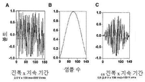
도 1a 내지 도 1c는 본 원에 설명된 원리에 따른 신경을 자극하기 위한 예시적인 전압 파형을 도시한다.
도 2는 본 원에 설명된 원리에 따른 페이싱(pacing) 중 전달되는 적분된 전압에 따른 신장 혈액 유동의 백분율 변화의 플롯이다.
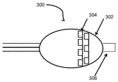
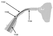
도 3a는 본 원에 설명된 원리에 따른 시술을 수행하는 데에 사용될 수 있는 예시적인 장치를 도시한다.
도 3b는 본 원에 설명된 원리에 따른 예시적인 유동 센서를 도시한다.
도 4a 및 도 4b는 본 원에 설명된 원리에 따른 예시적인 장치의 예시적인 구현예를 도시한다.
도 5는 본 원에 설명된 원리에 따른 전자 회로 및 유동 센서의 예시적인 구현예를 도시한다.
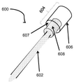
도 6a 내지 도 6d는 본 원에 설명된 원리에 따른 예시적인 유동 센서 또는 예시적인 가열 요소를 도시한다.
도 7a는 본 원에 설명된 원리에 따른 다른 예시적인 장치를 도시한다.
도 7b는 본 원에 설명된 원리에 따른 다른 예시적인 장치를 도시한다.
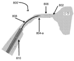
도 8a 및 도 8b는 본 원에 설명된 원리에 따른 도 7a 및 도 7b의 예시적인 유동 센서의 작동을 도시한다.
도 9는 본 원에 설명된 원리에 따른 차동 전치 증폭기(differential pre-amplifier)의 예시적인 단순 개략도를 도시한다.
도 10은 본 원에 설명된 원리에 따른 3-ω 획득 시스템의 예시적인 작동을 도시한다.
도 11은 본 원에 설명된 원리에 따른 예시적인 유동 센서의 작동을 도시한다.
도 12는 본 원에 설명된 원리에 따른 예시적인 유동 센서에 결합된 예시적인 PID 컨트롤러의 예시적인 블록도를 도시한다.
도 13은 본 원에 설명된 원리에 따른 동기 복조의 예를 도시한다.
도 14a 내지 도 14c는 본 원에 설명된 원리에 따른 예시적인 장치의 다양한 부품의 단면 층 구조를 도시한다.
도 15는 본 원에 설명된 원리에 따른 예시적인 평가를 수행하기 위한 예시적인 방법의 순서도를 도시한다.
도 16은 본 원에 설명된 원리에 따른 유동 측정의 예시적인 플롯을 도시한다.
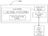
도 17은 본 원에 설명된 원리에 따른 평가 모듈을 포함하는 예시적인 시스템의 블록도를 도시한다.
도 18a는 본 원에 설명된 원리에 따른 예시적인 유동 센서를 도시한다.
도 18b는 본 원에 설명된 원리에 따른 예시적인 유동 센서를 사용하는 예시적인 측정을 도시한다.
도 19는 본 원에 설명된 원리에 따른 시술을 수행하는 예시적인 방법을 도시한다.
도 20은 본 원에 설명된 원리에 따른 예시적인 컴퓨터 시스템의 예시적인 구조를 도시한다.
도 21a 및 도 21b는 본 원에 설명된 원리에 따른 예시적인 장치를 사용하는 예시적인 측정의 결과를 도시한다.
도 22a 및 도 22b는 본 원에 설명된 원리에 따른 예시적인 장치의 예시적인 사용의 결과를 도시한다.
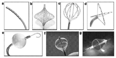
도 23a 내지 도 23g는 본 원에 설명된 원리에 따른 다중 전극 및 벌룬 카테터 장치의 예를 도시한다.
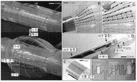
도 24a 내지 도 24d는 카테터 장치의 예를 도시한다.
도 24e 및 도 24f는 본 원에 설명된 원리에 따른 감지의 예시적인 형태를 나타낸다.
도 25는 본 원에 설명된 원리에 따른 카테터 상의 유동 센서의 비한정적 예를 도시한다.
도 26은 본 원에 설명된 원리에 따른 나선형 카테터 상의 유동 센서의 예를 도시한다.
도 27은 본 원에 설명된 원리에 따른 바이폴라 전극 및 금속 상호 연결부를 갖는 카테터를 도시한다.
도 28a 내지 도 28d는 본 원에 설명된 원리에 따른 데이터 또는 분석의 예시적인 표시를 도시한다.
도 29는 본 원에 설명된 원리에 따른 데이터 및 플롯의 예시적인 표시를 도시한다.Those skilled in the art will appreciate that the drawings described herein are exemplary only and that the drawings are not intended to limit the scope of the teachings set forth in any way. In some instances, various aspects or features may be shown exaggerated or enlarged to facilitate an understanding of the concepts of the invention described herein (the drawings are not necessarily drawn to scale, and instead, (Emphasis is placed on illustrating). In the drawings, like elements throughout the various views are generally designated with the same reference numerals for functionally similar and / or structurally similar elements.
Figures 1A-1C illustrate exemplary voltage waveforms for stimulating the nerves in accordance with the principles described herein.
Figure 2 is a plot of the percentage change in renal blood flow according to the integrated voltage delivered during pacing according to the principles described herein.
Figure 3A illustrates an exemplary apparatus that may be used to perform procedures in accordance with the principles described herein.
Figure 3B illustrates an exemplary flow sensor in accordance with the principles described herein.
Figures 4A and 4B illustrate an exemplary implementation of an exemplary apparatus in accordance with the principles described herein.
FIG. 5 illustrates an exemplary implementation of an electronic circuit and flow sensor in accordance with the principles described herein.
6A-6D illustrate an exemplary flow sensor or exemplary heating element in accordance with the principles described herein.
FIG. 7A illustrates another exemplary apparatus in accordance with the principles described herein.
Figure 7B illustrates another exemplary apparatus in accordance with the principles described herein.
Figures 8A and 8B illustrate the operation of the exemplary flow sensor of Figures 7A and 7B in accordance with the principles described herein.
Figure 9 shows an exemplary simple schematic diagram of a differential pre-amplifier according to the principles described herein.
10 illustrates an exemplary operation of a 3 -ω acquisition system in accordance with the principles described herein.
11 illustrates the operation of an exemplary flow sensor in accordance with the principles described herein.
12 illustrates an exemplary block diagram of an exemplary PID controller coupled to an exemplary flow sensor in accordance with the principles described herein.
13 shows an example of synchronous demodulation according to the principle described in this section.
Figures 14A-14C illustrate cross-sectional layer structures of various components of an exemplary device in accordance with the principles described herein.
Figure 15 shows a flow diagram of an exemplary method for performing an exemplary evaluation in accordance with the principles described herein.
Figure 16 shows an exemplary plot of flow measurement in accordance with the principles described herein.
17 shows a block diagram of an exemplary system including an evaluation module in accordance with the principles described herein.
18A illustrates an exemplary flow sensor in accordance with the principles described herein.
18B illustrates an exemplary measurement using an exemplary flow sensor in accordance with the principles described herein.
19 illustrates an exemplary method of performing a procedure in accordance with the principles described herein.
Figure 20 illustrates an exemplary structure of an exemplary computer system in accordance with the principles described herein.
Figures 21A and 21B illustrate the results of an exemplary measurement using an exemplary apparatus according to the principles described herein.
Figures 22A and 22B illustrate the results of an exemplary use of an exemplary apparatus in accordance with the principles described herein.
23A-23G illustrate examples of multiple electrode and balloon catheter devices in accordance with the principles described herein.
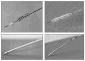
24A-24D illustrate an example of a catheter device.
24E and 24F illustrate an exemplary form of sensing in accordance with the principles described herein.
Figure 25 illustrates a non-limiting example of a flow sensor on a catheter in accordance with the principles described herein.
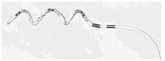
Figure 26 shows an example of a flow sensor on a spiral catheter according to the principles described herein.
27 illustrates a catheter having bipolar electrodes and metal interconnects in accordance with the principles described herein.
Figures 28A-28D illustrate exemplary representations of data or analysis in accordance with the principles described herein.
29 illustrates an exemplary representation of data and plots in accordance with the principles described herein.
유연성 중합체 내에 얇아진 칩을 내장하는 장치 및 시스템과 연관된 다양한 개념 및 이 장치 및 시스템의 실시예가 아래에서 보다 상세하게 설명된다. 개시된 개념이 구현예의 임의의 특정 방식에 한정되지 않으므로, 위에서 도입되고 아래에서 보다 상세하게 설명되는 다양한 개념은 임의의 수많은 방식으로 구현될 수 있는 것으로 이해되어야 한다. 특정 구현예 및 응용예가 주로 예시적인 목적으로 제공된다.Various concepts associated with devices and systems incorporating thinned chips in flexible polymers and embodiments of such devices and systems are described in more detail below. It is to be understood that the concepts described above are not limited to any particular mode of implementation, and that various concepts introduced above and described in greater detail below may be implemented in any number of ways. Certain embodiments and applications are provided primarily for illustrative purposes.
본 원에 사용되는 "포함하는(includes)"이라는 용어는 포함하지만 이에 한정되지 않는 것을 의미하며, "포함하는(including)"이라는 용어는 포함하지만 이에 한정되지 않는 것을 의미한다. "기준으로(based on)"라는 용어는 적어도 부분적으로 기준으로 하는 것을 의미한다. 본 원에 사용된, "상에 배치된(disposed on)" 또는 "위에 배치된(disposed above)"이라는 용어는 "적어도 부분적으로 내장되는"을 포함하는 것으로 정의된다.As used herein, the term " includes "is intended to include but is not limited to, including " including" The term "based on" means at least partly by reference. As used herein, the term " disposed on "or " disposed above" is defined to include "at least partially embedded.
본 원의 원리의 다양한 예와 연관되어 본 원에 설명된 기질 또는 다른 표면에 대하여, "상면(top surface)" 및 "저면(bottom surface)"에 대한 임의의 참조가 기질 및 서로에 대한 다양한 요소/부품의 상대적인 위치, 정렬 및/또는 배향을 나타내는 데에 주로 사용되며, 이러한 용어는 반드시 기준의 임의의 특정 프레임(예를 들면, 기준의 중력 프레임)을 나타내는 것은 아니다. 그러므로, 기질 또는 층의 "저부(bottom)"에 대한 기준은 지시된 표면 또는 층이 지면과 대면하고 있을 것을 반드시 필요로 하지 않는다. 마찬가지로, "위(over)", "아래(under)", "위(above)", "아래(beneath)" 등과 같은 용어는 반드시 기준의 중력 프레임과 같은 기준의 임의의 특정 프레임을 나타내지는 않지만, 주로 기질(또는 다른 표면) 및 서로에 대한 다양한 요소/부품의 상대적인 위치, 정렬 및/또는 배향을 나타내는 데에 사용된다. "상에 배치된(disposed on)" "내에 배치된(disposed in)" 및 "위에 배치된(disposed over)"이라는 용어는 "부분적으로 내장되는"을 포함하는 "내장되는"의 의미를 포함한다. 또한, 특징 A가 특징 B "상에 배치되는", "사이에 배치되는" 또는 "위에 배치되는"에 대한 기준은 특징 A가 특징 B와 접촉하는 예뿐만 아니라 다른 층 및/또는 다른 부품이 특징 A 및 특징 B 사이에 위치되는 예를 포함한다.For substrates or other surfaces described herein in connection with the various examples of the present principles, any reference to "top surface" and "bottom surface" And / or orientation of the components, and these terms do not necessarily represent any particular frame of reference (e.g., a reference gravity frame). Therefore, the criteria for the "bottom" of the substrate or layer does not necessarily require that the indicated surface or layer is facing the ground. Likewise, terms such as "over," "under," "above," "below," and the like do not necessarily denote any particular frame of reference such as a reference gravity frame , Are used primarily to indicate the relative location, alignment and / or orientation of the substrate (or other surface) and various elements / components to each other. "Disposed on" The term " disposed in "and" disposed over "include the meaning of" embedded " . It should also be noted that the criteria for feature A to be placed on feature B ", "placed between" or "above " A and Feature B, respectively.
신장 탈신경 요법은 RF 에너지, 가열, 또는 극저온(극히 차가움) 형태의 에너지를 신경에 가하는 것을 포함하여 절제를 통해 신장 신경을 분열시키는 데에 사용될 수 있다. 이는 튜브 또는 카테터를 서혜부에 삽입하여 장치를 신장 동맥 내로 안내하는 것에 의해 수행될 수 있다. 신장 탈신경 시술은 보통 과정의 효능의 측정을 제공하도록 구성되지 않는다.Renal neuronotherapy can be used to break the kidneys through resection, including applying energy to the nerves in the form of RF energy, heating, or cryogenic (extremely cool) form. This can be done by inserting a tube or catheter into the inguinal area and guiding the device into the renal artery. Nephrotic neurotomy is not usually configured to provide a measure of the efficacy of a procedure.
본 원에 설명된 원리에 따른 유동 감지를 갖는 카테터를 사용하여 적용될 수 있는 절제 에너지의 다른 비한정적 예는 무선 주파수(RF), 초음파 에너지, 극저온절제, 약물 기반 절제, 알코올 주입, 마이크로웨이브 에너지 절제 및 광(light) 기반 절제(레이저 에너지)를 포함한다.Other non-limiting examples of ablation energy that may be applied using catheters with flow sensing in accordance with the principles described herein include radio frequency (RF), ultrasound energy, cryogenic ablation, drug-based ablation, alcohol injection, microwave energy ablation And light based ablation (laser energy).
평가의 설명이 신장 동맥에 대한 시술에 대하여 설명되지만, 시술의 효능의 평가는 다른 조직계에서 수행될 수 있다. 예를 들면, 본 원에 설명된 유동 측정을 사용하여 시술의 효능을 판단하기 위한 평가는, 유동이 평가될 수 있는 폐 정맥, 관상 동맥, 말초 혈관, 심장 루멘 및 임의의 다른 루멘과 같은 다른 조직 루멘에서 수행되는 시술에 적용될 수 있다.Although the description of the evaluation is described with respect to the procedure for the renal artery, the evaluation of the efficacy of the procedure can be performed in other tissue systems. For example, an assessment to determine the efficacy of a procedure using the flow measurements described herein may be based on the use of other tissues such as pulmonary veins, coronary arteries, peripheral blood vessels, heart lumens and any other lumen, It can be applied to a procedure performed in a lumen.
탈신경 요법은, 경동맥동, 경동맥체, 미주 신경, 폐동맥, 복강 신경절 또는 방광 삼각층에 한정되지 않지만 이와 같은 다른 조직계에서, (RF 에너지, 가열, 또는 극저온(극히 차가움)을 신경에 가하는 것과 같은) 본 원에 설명된 형태 중 임의의 형태의 에너지를 가하는 것을 포함하여 절제를 통해 신경을 분열시키는 데에 사용될 수 있다.Dennation therapy is not limited to carotid arteries, carotid arteries, vagal nerves, pulmonary arteries, the parietal ganglia, or the bladder triangles, but in other such systems (such as RF energy, heating, or cryogenic ) Can be used to divide the nerve through ablation, including the application of any of the forms described herein.
신장 동맥에서의 혈류의 증가는 신장 교감 탈신경(RSDN) 시술의 효능의 정도의 지표로서 사용될 수 있다. 예를 들면, 혈류량의 증가의 표시는, 목표로 하는 조직에서 원하는 정도 및/또는 양의 탈신경을 달성하는 데에 RSDN 시술이 효과적이라는 것을 나타내는 지표로서 고려될 수 있다. 이러한 효능의 정도의 표시는 혈액의 유량이 원하는 레벨에 접근하고 있는 경우 시술에 종료점의 신호를 전달하는 것으로 추정될 수 있다. 다른 예로서, 혈류량이 적게 변화하거나 혈류량의 변화가 없다는 표시는 목표로 하는 조직에서 원하는 정도 및/또는 양의 탈신경을 달성하는 데에 RSDN 시술이 효과적이지 않거나 미미하게 효과적이라는 것을 나타내는 지표로서 고려될 수 있다. 이러한 효능의 정도의 표시는 원하는 성과, 또는 RSDN 시술을 더 효과적으로 하기 위해 이루어질 수 있는 잠재적인 변화를 달성하기 위해 수행될 추가적인 시술의 예상되는 횟수를 판단하는 데에 사용될 것으로 추정될 수 있다.Increased blood flow in the renal arteries can be used as an indicator of the degree of efficacy of the renal sympathetic denervation (RSDN) procedure. For example, an indication of an increase in blood flow may be considered as an indicator that the RSDN procedure is effective in achieving the desired degree and / or amount of denervation in the targeted tissue. An indication of this degree of efficacy can be assumed to convey an endpoint signal to the procedure if the blood flow rate is approaching the desired level. As another example, an indication that the blood flow volume is small or that there is no change in the blood flow is considered as an index indicating that the RSDN procedure is ineffective or marginally effective in achieving the desired degree and / or amount of denervation in the target tissue . An indication of the degree of such efficacy may be assumed to be used to determine the expected outcome or the expected number of additional procedures to be performed to achieve a potential change that may be made to make the RSDN procedure more effective.
본 원에 설명된 원리에 따르면, 탈신경 시술, 또는 페이싱(pacing) 또는 다른 자극 시술의 효능을 판단하는 예시적인 장치 및 방법이 설명된다. 시술의 단계를 감시하거나 시술의 수행의 종료점을 판단하기 위해 탈신경 또는 페이싱(또는 다른 자극) 시술의 이전 및/또는 이후의 혈액 유량 또는 다른 유체 유량의 변화를 감시하는 것에 관한 예시적인 방법이 개시된다.According to the principles described herein, exemplary devices and methods for determining the efficacy of neurotomy, or pacing or other stimulation procedures, are described. An exemplary method for monitoring changes in blood flow or other fluid flow before and / or after a denervation or pacing (or other stimulation) procedure to monitor the steps of the procedure or to determine the end point of the performance of the procedure is disclosed do.
이러한 개시는 신장 탈신경 또는 페이싱(또는 다른 자극) 시술에 한정되지 않지만 이와 같은 탈신경 시술을 포함하는 중재적 시술의 효능을 판단하기 위해 구현될 수 있는 유동 측정 시스템에 관한 것이다. 본 원에 설명된 예 및 방법에 따르면, 조직 루멘을 통과하는 혈액의 유량의 변화는 (신장 동맥에 한정되지 않지만 이와 같은) 조직에 대해 수행된 시술의 유효성의 표시를 제공하는 데에 사용될 수 있다. 이 시술은, 예를 들면, RF 에너지, 가열 또는 극저온(극히 차가움) 형태의 에너지를 신경에 가하는 것을 포함하여 절제를 통해 신경을 분열시키기 위한 임의의 시술일 수 있다. 본 원에 설명된 유동 측정 시스템, 장치 및 방법의 예시적인 적용은 임상 시술이 성공적이라는 표시를 의사에게 제공하기 위한 것이다.This disclosure is directed to a flow measurement system that can be implemented to determine the efficacy of an interventional procedure including, but not limited to, renal or neurosurgical (or other stimulation) procedures. According to the examples and methods described herein, changes in the flow rate of blood through the tissue lumen can be used to provide an indication of the effectiveness of the procedure performed on the tissue (although not limited to the kidney arteries) . This procedure may be any procedure for dissecting the nerve through ablation, including, for example, applying energy to the nerve in the form of RF energy, heating or cryogenic (extremely cold) form. An exemplary application of the flow measurement system, apparatus, and method described herein is to provide the physician with an indication that the clinical procedure is successful.
본 원에 설명된 원리에 따르면, 신장 동맥 또는 다른 조직의 시술에서 임상 종료점을 수립하는 데에 사용되는 예시적인 장치 및 방법이 설명된다. 예시적인 시스템 및 방법에서, 시술 이전에 및/또는 시술에 후속하여 신장 동맥 또는 다른 조직에서의 혈류의 측정치가 시술의 효능의 표시를 제공하기 위해 사용될 수 있다. 다른 예에서, 시술 전 사이클 및/또는 시술 후 사이클 도중, 혈류 측정이, 예를 들면, RF 에너지, 가열 또는 극저온(극히 차가움) 형태의 에너지를 신경에 가하는 것을 포함하여 절제를 통해 신경을 분열시키기 위해 수행되는 시술의 임상 종료점을 수립하는 데에 사용될 수 있다.According to the principles described herein, exemplary devices and methods for use in establishing a clinical endpoint in the treatment of kidney arteries or other tissues are described. In an exemplary system and method, measurements of blood flow in the kidney artery or other tissue prior to and / or following the procedure may be used to provide an indication of the efficacy of the procedure. In another example, during pre- and / or post-procedure cycles, blood flow measurements may include splitting the nerves through ablation, including applying energy to the nerve, for example in the form of RF energy, heating or cryogenic Can be used to establish the clinical endpoint of the procedure being performed for the patient.
교감 신경 활동은 혈관 수축을 통하여 혈압 및 유동을 제어한다. 교감 신경으로의 전기 자극의 전달이, 결국, 신경을 자극시키는 데에 사용되어 혈류 또는 다른 유체 유동을 조정한다. 본 원에 설명된 원리에 따른, RSDN 시술에 한정되지 않지만 이와 같은 시술 중 국지적 혈류 및/또는 압력의 변화를 측정하는 예시적인 장치 및 방법이 설명된다.Sympathetic activity controls blood pressure and flow through vasoconstriction. The delivery of electrical stimulation to the sympathetic nerve, eventually, is used to stimulate the nerves to regulate blood flow or other fluid flow. Exemplary devices and methods for measuring changes in local blood flow and / or pressure during, but not limited to, RSDN procedures in accordance with the principles described herein are described.
현재, 고성능 전자 기기 및 전극의 대부분의 형태는 강성이고, 부피가 크며 본질적으로 밀도가 낮고 동맥의 연질의 복잡한 위상과 호환되지 않는 원통형 커프 형태를 갖는다. 다양한 예시적인 구현예에서, 연질이고 유연성인 나노멤브레인 유동 감지의 어레이를 구축하기 위한 신규한 미세 가공 기술과, 동시에 페이싱 에너지 및/또는 절제 에너지를 전달하면서 신장 혈류에 관한 피드백을 제공하는 데에 사용될 수 있는 전극 요소를 포함하는 신규한 다기능성 카테터 장치가 설명된다. 본 원에 설명된 다양한 예에서, 동시에 유동을 측정하며 RF 에너지 및 페이싱 에너지를 신장 동맥 내측에 가하는 나선형 벌룬 카테터에 한정되지 않지만 이와 같은 카테터 장치에서 고성능 유연성 유동 센서 및 전극 어레이를 달성하기 위해 무기 반도체 처리를 사용하는 신규한 디자인 전략 및 가공 기법이 설명된다.At present, most forms of high performance electronics and electrodes are rigid, bulky, inherently densely cylindrical and have a cylindrical cuff shape that is incompatible with the complex phase of softness of the arteries. In various exemplary embodiments, a novel micromachining technique for constructing an array of soft and flexible nanomembrane flow sensing, and a method for providing feedback about the renal blood flow while simultaneously delivering pacing energy and / or ablation energy A novel multifunction catheter device is described which includes an electrode element that is capable of being actuated. In various examples described herein, to achieve a high performance flexible flow sensor and electrode array in a catheter device, such as but not limited to a helical balloon catheter that simultaneously measures flow and applies RF energy and pacing energy inside the renal artery, New design strategies and processing techniques using processing are described.
본 원에 설명된 원리에 따른 예시적인 카테터 장치는 적어도 하나의 페이싱 전극을 포함할 수 있다. 페이싱 시술에서, 혈류를 자극하기 위해 신경에 근접한 조직의 일부분에 전위가 인가된다. 도 1a 내지 도 1c는 신경을 자극하는 데에 사용될 수 있는 예시적인 전압 파형을 도시한다. 도 2는 페이싱 중 전달되는 적분된 전압에 따른 신장 혈액 유동의 백분율 변화의 플롯이다. 도 1a 내지 도 1c 및 도 2는 프로그램된 신경 자극(페이싱 중)으로 인해 신장 동맥에서 혈류가 변화될 수 있다는 것을 나타낸다. 일 예에서, 이러한 페이싱은 본 원에 설명된 원리에 따라 수행되는 시술 중에 수행될 수 있다. 예를 들면, 시술 이전, 도중 및/또는 이후에, 예를 들면, 신경 소스(source)의 영역에서 조직에 전기 자극을 제공하기 위해, 적어도 하나의 페이싱 전극이 본 원에 설명된 예시적인 카테터 장치에 배치될 수 있다. 이 시술은 RF 에너지, 가열 또는 극저온(극히 차가움) 형태의 에너지를 신경에 가하는 것을 포함하여 절제를 통해 신장 신경을 분열시키는 임의의 시술일 수 있다.An exemplary catheter device in accordance with the principles set forth herein may include at least one pacing electrode. In the pacing procedure, a potential is applied to a portion of the tissue proximate to the nerve to stimulate blood flow. Figures 1A-1C illustrate exemplary voltage waveforms that may be used to stimulate the nerve. Figure 2 is a plot of the percentage change in renal blood flow according to the integrated voltage delivered during pacing. Figures 1A-1C and 2 show that the blood flow can be changed in the renal artery due to the programmed nerve stimulation (during pacing). In one example, such pacing may be performed during a procedure performed in accordance with the principles described herein. For example, to provide electrical stimulation to tissue prior to, during, and / or after a procedure, for example, in the area of a nerve source, at least one pacing electrode may be placed in the exemplary catheter device As shown in FIG. The procedure may be any procedure that disrupts the kidney via ablation, including applying energy to the nerve in the form of RF energy, heating or cryogenic (extremely cool) form.
단일의 카테터 장치에 조직에 대해 시술을 수행하는 부품 및 혈액의 유량을 감지하는 부품을 결합한 본 원에 설명된 원리에 따른 예시적인 장치 및 방법이 설명된다. 또한, 단일의 카테터 장치에 (예컨대 페이싱 전극을 사용하여) 신경 자극을 수행하는 부품 및 혈액의 유량을 감지하는 부품을 결합한 본 원에 설명된 원리에 따른 예시적인 장치 및 방법이 설명된다. 일 예에서, 카테터 장치를 사용한 측정을 기반으로 하는 혈액의 유량의 표시는 RSDN 시술을 포함하는 시술 중 임상 종료점을 수립하는 데에 사용될 수 있다.Exemplary devices and methods in accordance with the principles set forth herein are described that combine a single catheter device with a component that performs procedures for tissue and a component that senses the flow rate of blood. In addition, an exemplary apparatus and method in accordance with the principles described herein combining a component that performs nerve stimulation (e.g., using a pacing electrode) and a component that senses the flow rate of blood in a single catheter device is described. In one example, an indication of blood flow based on measurements using a catheter device can be used to establish a clinical endpoint during the procedure, including RSDN procedures.
도 3a는, 본 원에 설명된 원리에 따른, 시술을 수행하는 데에 사용될 수 있는 예시적인 장치(300)를 도시한다. 예시적인 장치(300)는 팽창 가능하고/하거나 확장 가능한 몸체(302)와, 팽창 가능하고/하거나 확장 가능한 몸체(302)의 일부분에 배치되는 유동 센서(304)와, 팽창 가능하고/하거나 확장 가능한 몸체(302)에 배치되는 전자 회로(306)를 포함한다. 전자 회로(306)는 팽창 가능하고/하거나 확장 가능한 몸체(302)의 팽창을 수용하는 다수의 부품을 포함한다. 도 3a에서, 유동 센서(304)는 팽창 가능 몸체의 원위부에 배치되는 것으로 도시된다. 다른 예에서, 유동 센서는 팽창 가능하고/하거나 확장 가능한 몸체의 근위부에 배치될 수 있거나 이와 근접하게 배치될 수 있다.Figure 3A illustrates an
예시적인 구현예에서, 유동 센서는 도 3b에 도시된 바와 같이 형성될 수 있다. 도 3b는 온도 센서(308)에 근접하게 배치되는 가열 요소(307)를 포함하는 예시적인 유동 센서(306')를 도시한다. 가열 요소(307) 및 온도 센서(308)는 지지부(309)에 배치되거나 봉지될 수 있다. 지지부(309)는 열전도성 재료로 이루어질 수 있다. 다양한 예에서, 가열 요소(307)는 분리부 "x"만큼 온도 센서(308)로부터 분리될 수 있다. 파라미터 "x"는 약 1 mm, 약 2 mm, 약 3 mm, 약 5 mm, 약 8 mm, 약 10 mm, 약 12 mm, 약 18 mm, 약 24 mm, 약 30 mm 또는 이 이상일 수 있다. 온도 센서(308)는 서모커플, 저항 온도 검출기(RTD) 온도 센서, 접합부 온위 센서(온도의 지표로서 접합부에 걸쳐 전압 측정치를 사용하는 센서를 포함), 서미스터, 집적 회로 온도 센서(LM35 시리즈 온도 센서를 포함) 또는 반도체 온도 센서일 수 있다. 예시적인 유동 센서(306')는 온도 센서의 온도 측정을 기반으로 조직 루멘 내의 혈액의 유량의 측정치를 제공할 수 있다. 작동 시, 가열 요소는 특정된 온도 측정 값으로 온도 센서를 유지하는 데에 사용된다. 가열 요소 및 온도 센서를 지나는 임의의 유체 유동은 온도 센서의 온도 측정을 약간 변화시키거나 변동시킬 수 있다. 가열 요소는 안정적인 특정된 온도 측정값에서 온도 센서를 유지하는 것을 시도하도록 구성된다. 온도 센서의 측정값의 약간의 변동을 일으키는 유체 유량의 변화는 가열 요소가 온도 센서를 특정된 측정값으로 유도하기 위해 그 열 출력을 증가시키거나 감소시키도록 한다. 유동 센서의 영역에서의 유체(예를 들면, 혈액)의 보다 빠른 유량은 가열 요소가 열 출력을 증가시키도록 할 수 있다. 유동 센서의 영역에서의 유체(예를 들면, 혈액)의 보다 느린 유량은 가열 요소가 열 출력을 감소시키도록 할 수 있다. 이에 따라, 가열 요소의 동작점의 변화는 온도 센서의 유체 측정의 유량의 표시를 제공하는 데에 사용될 수 있고, 팽창 가능하고/하거나 확장 가능한 몸체(302)에 근접한 유체의 유량의 표시를 제공하는 데에 사용될 수 있다.In an exemplary embodiment, the flow sensor may be formed as shown in Figure 3B. Figure 3B illustrates an exemplary flow sensor 306'including a
도 3b에 도시된 바와 같이, 지지부(309)는 가열 요소(307)를 도 3b에 도시된 바와 같은 "y"값만큼 유체로부터 분리하도록 구성될 수 있다. 파라미터 "y"는 약 2 mm, 약 3 mm, 약 5 mm, 약 8 mm, 약 10 mm, 약 12 mm, 약 15 mm 이상일 수 있다. 상이한 예시적인 구현예에서, 파라미터 "x" 및 "y"는 결과적인 예시적인 유동 센서의 동적 범위를 다르게 하도록 수정될 수 있다. 예를 들면, 예시적인 유동 센서의 전체 범위를 증가시키도록, "x"는 보다 커질 수 있고 "y"는 보다 작아질 수 있다. "y"의 값이 보다 작은 경우, 열이 보다 용이하게 영역 유체로 유동할 수 있다. "x" 값이 보다 큰 경우, 온도 센서를 원하는 특정 측정 설정점으로 이동시키도록 온도 센서 "x"의 위치로 유동하기에 충분한 열을 발생시키기 위해 보다 큰 동력이 소요될 수 있다. 이에 따라, 유동 센서는 가열 요소로의 작동 신호의 범위를 포함하는 보다 큰 전체 범위에 걸쳐 작동될 수 있다. 예를 들면, 이하에 설명된 바와 같이, 가열 요소로의 신호의 레벨/크기가 유체의 유량의 표시를 제공하는 데에 사용될 수 있다. 이러한 원리에 따른 가열 요소로의 작동 신호의 보다 큰 범위는 유체 유량을 판단하는 데에 사용하기 위한 보다 큰 범위의 값 및 보다 큰 데이터 자산 값을 제공할 수 있다. 예시적인 구현예에서, 시스템은 복수의 유동 센서를 포함할 수 있으며, 둘 이상의 유동 센서는 가열 요소 및 각각의 유동 센서 중 온도 센서 사이에 "x" 및 "y"의 값이 다르도록 구성된다. 이에 따라, 예시적인 시스템은 다양한 측정 범위를 나타내는 유동 센서를 제시한다.3B, the
본 원에 설명된 원리에 따른 예시적인 유동 센서는 열 '복사' 소스에 근접한 온도 센서를 포함할 수 있다. 본 원에 설명된 예시적인 시스템, 방법 및 장치 중 임의의 것에 따르면, 열복사를 제공할 수 있는 가열 요소의 비한정적 예는 저항성 히터 또는 열전 히터를 포함하는, 카테터와 결합될 수 있는 임의의 형태의 히터를 포함한다.An exemplary flow sensor in accordance with the principles described herein may include a temperature sensor proximate to a thermal 'radiation' source. According to any of the exemplary systems, methods, and apparatus described herein, a non-limiting example of a heating element that can provide thermal radiation is any type of heater that can be combined with a catheter, including a resistive heater or a thermoelectric heater And a heater.
본 원에 설명된 원리에 따른 임의의 예시적인 장치에서, 온도 센서는 저항 온도 검출기(RTD) 온도 센서, 서모커플, 접합부 온위 센서(온도의 지표로서의 접합부에 걸쳐 전압 측정치를 사용하는 센서를 포함), 서미스터, 집적 회로 온도 센서(LM35 시리즈 온도 센서를 포함) 및 반도체 온도 센서 중 적어도 하나를 포함할 수 있다. 다양한 예에서, 알려진 임피던스의 센서가 사용된다. 본 원에 설명된 시스템 및 방법 중 임의의 것에 따라 사용될 수 있는 센서의 다른 비한정적 예는 증착 금(gold) 저항기 및 세라믹 서미스터를 포함한다. 다른 예에서, 포일(foil)과 같은 다른 재료가 사용될 수 있다.In any of the exemplary devices according to the principles described herein, the temperature sensor may be a resistance temperature detector (RTD) temperature sensor, a thermocouple, a junction temperature sensor (including sensors that use voltage measurements across junctions as an indication of temperature) , A thermistor, an integrated circuit temperature sensor (including the LM35 series temperature sensor), and a semiconductor temperature sensor. In various examples, sensors of known impedance are used. Other non-limiting examples of sensors that can be used according to any of the systems and methods described herein include a deposition resistor and a ceramic thermistor. In another example, other materials such as foil may be used.
일 예에서, 가열 요소의 동작점을 유량에 상호 연관시키기 위해, 유동 센서(306')에 대한 교정 표준이 개발될 수 있다. 예를 들면, 트레이닝 샘플이 유동 측정을 변환하는 데에 사용될 수 있으며, 각 트레이닝 샘플은 비유량(specific flow rate)으로 유동하게 되는 유체이다. 가열 요소에 의한 가열 요소의 동작점의 주어진 양 및/또는 변화율에 대하여, 각각의 트레이닝 샘플에 대하여 유동 센서의 동작점이 얻어진다. 각 트레이닝 샘플의 유량은 알려져 있다(트레이닝 샘플에 대하여 미리 설정된 것으로 고려). 가열 요소에 의해 공급되는 가열의 양 및/또는 속도도 알려져 있다. 교정 데이터를 얻기 위해, 알려진 공급 가열을 알려진 유량과 상호 연관시키도록 교정 표준이 개발될 수 있다. 예시적인 교정 표준이 유동 센서 측정을 트레이닝 표준에 사용되는 유체와 유사한 특성을 갖는 유체에 대한 유량으로 변환시키는 데에 사용될 수 있다.In one example, a calibration standard for the flow sensor 306 'may be developed to correlate the operating point of the heating element to the flow rate. For example, a training sample can be used to convert flow measurements, and each training sample is a fluid that flows at a specific flow rate. For a given amount and / or rate of change of the operating point of the heating element by the heating element, the operating point of the flow sensor is obtained for each training sample. The flow rate of each training sample is known (considered to be preset for the training sample). The amount and / or speed of heating supplied by the heating element is also known. To obtain calibration data, calibration standards may be developed to correlate known supply heating with known flow rates. An exemplary calibration standard may be used to convert the flow sensor measurements to a flow rate for a fluid having properties similar to those used in the training standard.
예시적인 구현예에서, 도 3a 및 도 3b의 예시적인 장치는 팽창 가능하고/하거나 확장 가능한 몸체의 근위부에 결합되는 카테터의 일부분에 배치되는 유동 센서를 더 포함할 수 있다.In an exemplary embodiment, the exemplary device of Figs. 3A and 3B may further include a flow sensor disposed in a portion of the catheter that is coupled to the proximal portion of the inflatable and / or expandable body.
일 예에서, 전자 회로(306)는 팽창 가능하고/하거나 확장 가능한 몸체(302)에 배치되는 다수의 전극을 포함할 수 있다. 전극은 본 원에 설명된 원리에 따른 시술을 수행하는 데에 사용될 수 있다. 예를 들면, 전극 중 적어도 하나는 RF 전극에 근접한 조직 표면의 일부분으로 RF 에너지를 전달하는 무선 주파수(RF) 전극일 수 있다. 본 원에 설명된 원리에 따르면, 전달된 RF 에너지는, 신장 신경을 분열시키는 것을 포함하여, 조직을 수정하는 데에 사용된다.In one example,
다른 예에서, 장치(300)는 다른 양상을 사용하는 시술을 수행하는 부품을 포함할 수 있다. 예를 들면, 장치(300)는, 예를 들면, RF 에너지, 가열 또는 극저온(극히 차가움) 형태의 에너지를 신경에 가하는 것을 포함하여 절제를 통해 신장 신경을 분열시키기 위한 부품을 포함할 수 있다.In another example,
다른 예에서, 장치(300)의 전자 회로(306)는 적어도 하나의 페이싱 전극을 포함할 수 있다. 페이싱 전극은 페이싱 전극에 근접한 (신장 동맥에 한정되지 않지만 이와 같은) 조직의 일부분으로 전기 자극을 전달하도록 구현될 수 있다. 상술한 바와 같이, 페이싱 전극은 시술의 여러 단계에서 신경을 자극하는 데에 사용될 수 있다. 예를 들면, RF 에너지, 가열 또는 극저온(극히 차가움) 형태의 에너지를 신경에 가하는 것을 포함하여, 절제에 한정되지 않지만 이를 통하여, 신경을 분열시키도록 에너지를 전달하기 이전에, 페이싱 전극으로부터의 전기 자극이 신경을 자극시키도록 조직의 일부에 가해질 수 있다. 다른 예에서, RF 에너지, 가열 또는 극저온(극히 차가움) 형태의 에너지를 신경에 가하는 것을 포함하여, 절제에 한정되지 않지만 이를 통하여, 신경을 분열시키도록 에너지를 전달하는 것에 후속하여, 페이싱 전극으로부터의 전기 자극이 신경을 자극시키도록 조직의 일부에 가해질 수 있다.In another example,
다른 예에서, 전자 회로(306)는 또한 각각 전자 회로(306)의 전극에 근접하게 배치되는 온도 센서를 포함할 수 있다.In another example,
다른 예에서, 장치(300)는 페이싱 전극, 발광 장치, 접촉 센서, 이미지 검출기, 압력 센서, 생물학적 활동 센서, 온도 센서 또는 이들의 임의의 조합에 한정되지 않지만 이와 같은, 팽창 가능하고/하거나 확장 가능한 몸체에 배치되는 하나 이상의 다른 부품을 포함할 수 있다.In another example, the
도 4a 및 도 4b는 예시적인 장치(400)의 비한정적 예시적인 구현예를 도시한다. 예시적인 장치(400)는 팽창 가능하고/하거나 확장 가능한 몸체(402)와, 팽창 가능하고/하거나 확장 가능한 몸체(402)의 일부분에 배치되는 유동 센서(404)와, 팽창 가능하고/하거나 확장 가능한 몸체(402)에 배치되는 전자 회로(406)를 포함한다. 전자 회로(406)는 팽창 가능하고/하거나 확장 가능한 몸체(402)의 팽창을 수용하는 다수의 부품을 포함한다. 도 4a 및 도 4b에 도시된 바와 같이, 유동 센서(404)는 팽창 가능하고/하거나 확장 가능한 몸체(402)의 원위부에 배치될 수 있다. 비한정적 예로서, 확장 가능 및/또는 팽창 가능 구조의 원위 영역의 일부분이 돌출부를 형성하도록 연장될 수 있다. 유동 센서(404)는 돌출부에 장착될 수 있다. 다른 예에서, 유동 센서(404)는 팽창 가능하고/하거나 확장 가능한 몸체의 근위부에 배치될 수 있거나 이와 근접하게 배치될 수 있다.FIGS. 4A and 4B illustrate a non-limiting exemplary embodiment of an
예시적인 구현예에서, 유동 센서(404)는 온도 센서(408)에 근접하게 배치되는 가열 요소(407)를 포함하도록 형성될 수 있다. 다양한 예에서, 가열 요소(407)는 약 1 mm 또는 약 2 mm만큼 온도 센서(408)로부터 분리될 수 있다. 비한정적 예로서, 가열 요소(407)는 온도 제어된 가열 요소일 수 있다. 비한정적 예로서, 온도 센서(408)는 서미스터일 수 있다.In an exemplary embodiment, the
도 4a 및 도 4b의 비한정적 예에서, 전자 회로는 팽창 가능하고/하거나 확장 가능한 몸체(402)에 배치되는 다수의 전극(410)을 포함할 수 있다. 전극은 본 원에 설명된 원리에 따른 시술을 수행하는 데에 사용될 수 있다. 예를 들면, 전극(410) 중 적어도 하나는 RF 전극에 근접한 조직 표면의 일부분으로 RF 에너지를 전달하는 무선 주파수(RF) 전극일 수 있다. 본 원에 설명된 원리에 따르면, 전달된 RF 에너지는, 신장 신경을 분열시키는 것을 포함하여, 조직을 수정하는 데에 사용된다.In the non-limiting example of Figures 4A and 4B, the electronic circuitry may include a plurality of
도 4a 및 도 4b의 비한정적 예에 도시된 바와 같이, 예시적인 장치(400)의 전자 회로(406)는 팽창 가능하고/하거나 확장 가능한 몸체(402)의 표면에 배치되는 연신 가능 상호 연결부(412)를 포함할 수 있다. 도 4b에 도시된 바와 같이, 연신 가능 상호 연결부는 복수의 전극(410) 중 적어도 하나를 외부 회로에 전기적으로 결합시키는 데에 사용될 수 있다.4A and 4B, the
도 4a 및 도 4b의 비한정적 예에 도시된 바와 같이, 예시적인 장치(400)의 전자 회로(406)는 또한 메인 버스(414)를 포함할 수 있다. 도 4b에 도시된 바와 같이, 연신 가능 상호 연결부(412)는 전극(410)을 메인 버스(414)에 전기적으로 결합시킨다. 또한, 도 4b에 도시된 바와 같이, 메인 버스(414)는 전극(410)을 외부 회로에 전기적으로 결합시키는 것을 용이하게 하기 위해 팽창 가능하고/하거나 확장 가능한 몸체(402)를 넘어 연장될 수 있다.The
다른 예에서, 장치(400)의 전자 회로(406)의 전극(410) 중 적어도 하나는 페이싱 전극일 수 있다. 페이싱 전극은 페이싱 전극에 근접한 (신장 동맥에 한정되지 않지만 이와 같은) 조직의 일부분으로 전기 자극을 전달하도록 구현될 수 있다. 상술한 바와 같이, 페이싱 전극은 시술의 여러 단계에서 신경을 자극하는 데에 사용될 수 있다. 예를 들면, RF 에너지, 가열 또는 극저온(극히 차가움) 형태의 에너지를 신경에 가하는 것을 포함하여, 절제에 한정되지 않지만 이를 통하여, 신경을 분열시키도록 에너지를 전달하기 이전에, 페이싱 전극으로부터의 전기 자극이 신경을 자극시키도록 조직의 일부에 가해질 수 있다. 다른 예에서, RF 에너지, 가열 또는 극저온(극히 차가움) 형태의 에너지를 신경에 가하는 것을 포함하여, 절제에 한정되지 않지만 이를 통하여, 신경을 분열시키도록 에너지를 전달하는 것에 후속하여, 페이싱 전극으로부터의 전기 자극이 신경을 자극시키도록 조직의 일부에 가해질 수 있다.In another example, at least one of the
다른 예에서, 장치(400)는 다른 양상을 사용하는 시술을 수행하는 부품을 포함할 수 있다. 예를 들면, 장치(400)는, 예를 들면, RF 에너지, 가열 또는 극저온(극히 차가움) 형태의 에너지를 신경에 가하는 것을 포함하여 절제를 통해 신장 신경을 분열시키기 위한 부품을 포함할 수 있다.In another example,
다른 예에서, 장치(400)는 페이싱 전극, 발광 장치, 접촉 센서, 이미지 검출기, 압력 센서, 생물학적 활동 센서, 온도 센서 또는 이들의 임의의 조합에 한정되지 않지만 이와 같은, 팽창 가능하고/하거나 확장 가능한 몸체에 배치되는 하나 이상의 다른 부품을 포함할 수 있다.In another example,
다른 예에서, 장치(400)는 또한 각각 전자 회로(406)의 전극(410)에 근접하게 배치되는 온도 센서를 포함할 수 있다.In another example,
도 5는 카테터에 배치될 수 있고 본 원에 설명된 원리에 따른 예시적인 장치의 샤프트로 연장될 수 있는 전자 회로(506) 및 유동 센서(504)의 비한정적 예시적인 구현예를 도시한다. 전자 회로(506)는 다수의 전극(510)을 포함한다. 다양한 예에서, 전극(510)은 팽창 가능하고/하거나 확장 가능한 몸체의 표면에 부합하는 적합한 전극일 수 있다. 도 5에 도시된 바와 같이, 유동 센서(504)는 온도 센서(808)에 근접하게 배치되는 가열 요소(507)를 포함한다. 비한정적 예로서, 가열 요소(507)는 온도 제어된 가열 요소일 수 있다. 비한정적 예로서, 온도 센서(508)는 서미스터일 수 있다.FIG. 5 illustrates a non-limiting exemplary embodiment of an
도 5의 비한정적인 예에서, 전극(510) 중 적어도 하나는 RF 전극에 근접한 조직 표면의 일부분으로 RF 에너지를 전달하는 무선 주파수(RF) 전극일 수 있다. 본 원에 설명된 원리에 따르면, 전달된 RF 에너지는, 신장 신경을 분열시키는 것을 포함하여, 조직을 수정하는 데에 사용된다. 전극(510) 중 적어도 하나는, 본 원에 설명된 바와 같이, 전기 자극을 신경으로 전달하는 페이싱 전극일 수 있다.In the non-limiting example of FIG. 5, at least one of the
도 5의 비한정적 예에 도시된 바와 같이, 전자 회로(506)는 팽창 가능하고/하거나 확장 가능한 몸체의 표면에 배치되는 연신 가능 상호 연결부(512)를 포함한다. 연신 가능 상호 연결부(512)는 복수의 전극(510) 중 적어도 하나를 외부 회로에 전기적으로 결합시키는 데에 사용될 수 있다.As shown in the non-limiting example of FIG. 5, the
또한, 도 5의 비한정적 예에 도시된 바와 같이, 전자 회로(506)는 또한 메인 버스(514)를 포함한다. 도 5에 도시된 바와 같이, 연신 가능 상호 연결부(512)는 전극(510)을 메인 버스(514)에 전기적으로 결합시킨다. 또한, 도 5에 도시된 바와 같이, 메인 버스(514)는 전극(510)을 외부 회로에 전기적으로 결합시키는 것을 용이하게 하는 연결 패드(516)를 포함한다.In addition, as shown in the non-limiting example of FIG. 5, the
도 6a는 본 원에 설명된 원리에 따른 시술을 수행하는 데에 사용될 수 있는 예시적인 장치(600)의 일부분을 도시한다. 예시적인 장치(300)는 세장형 부재(602)와, 세장형 부재(602)의 원위부에 배치되는 유동 센서(604)를 포함한다. 도 6a에서, 유동 센서(604)는 세장형 부재의 원위부에 배치되는 것으로 도시된다. 다른 예에서, 유동 센서는 세장형 부재의 근위부에 배치되거나 이에 근접하게 배치될 수 있거나, 세장형 부재에 결합되는 팽창 가능하고/하거나 확장 가능한 몸체의 근위부 또는 원위부에 배치될 수 있다.6A illustrates a portion of an
이러한 예시적인 구현예에서, 유동 센서는 도 6a에 도시된 바와 같이 형성될 수 있으며, 가열 요소(606) 및 온도 센서(608)를 포함한다. 가열 요소(606)는 캐비티(607)를 포함한다. 도 6a에 도시된 바와 같이, 온도 센서(608)의 적어도 일부분은 캐비티(607)의 일부분에 수용된다. 위에서 도 3a 및 도 3b의 유동 센서를 참조로 설명된 것과 마찬가지로, 가열 요소(606)는 세장형 부재(602)에 근접한 영역을 가열하는 데에 사용될 수 있다. 온도 센서(608)의 온도 측정은 유동 센서(604)에 근접한 유체의 유량의 표시를 제공하는 데에 사용될 수 있다. 예를 들면, 유체가 보다 높은 유량을 가져 가열 요소에 근접한 영역으로부터 열을 흡수한다면, 온도 센서는 유체 유량이 보다 낮은 경우에 얻어진 것과 상이한 측정을 기록할 수 있다.In this exemplary embodiment, a flow sensor may be formed as shown in FIG. 6A and includes a
작동 시, 가열 요소는 특정된 온도 측정 값으로 온도 센서를 유지하는 데에 사용된다. 가열 요소 및 온도 센서를 지나는 임의의 유체 유동은 온도 센서의 온도 측정을 약간 변화시키거나 변동시킬 수 있다. 가열 요소는 안정적인 특정된 온도 측정값으로 온도 센서를 유지하는 것을 시도하도록 구성된다. 온도 센서의 측정값의 약간의 변동을 일으키는 유체 유량의 변화는 가열 요소가 온도 센서를 특정된 측정값으로 유도하기 위해 그 열 출력을 증가시키거나 감소시키도록 한다. 유동 센서의 영역에서의 유체(예를 들면, 혈액)의 보다 빠른 유량은 가열 요소가 열 출력을 증가시키도록 할 수 있다. 유동 센서의 영역에서의 유체(예를 들면, 혈액)의 보다 느린 유량은 가열 요소가 열 출력을 감소시키도록 할 수 있다. 이에 따라, 가열 요소의 동작점의 변화는 온도 센서의 유체 측정의 유량의 표시를 제공하는 데에 사용될 수 있고, 팽창 가능하고/하거나 확장 가능한 몸체(302)에 근접한 유체의 유량의 표시를 제공하는 데에 사용될 수 있다.In operation, the heating element is used to maintain the temperature sensor at a specified temperature reading. Any fluid flow past the heating element and the temperature sensor may slightly vary or vary the temperature measurement of the temperature sensor. The heating element is configured to attempt to maintain the temperature sensor with a stable specified temperature measurement value. A change in the fluid flow rate that causes a slight variation in the measured value of the temperature sensor causes the heating element to increase or decrease its heat output to drive the temperature sensor to the specified measured value. A faster flow rate of the fluid (e.g., blood) in the region of the flow sensor may cause the heating element to increase the heat output. A slower flow rate of the fluid (e.g., blood) in the region of the flow sensor may cause the heating element to reduce the heat output. Thus, a change in the operating point of the heating element can be used to provide an indication of the flow rate of the fluid measurement of the temperature sensor, and provides an indication of the flow rate of the fluid proximate the inflatable and / or
또한, 위에서 도 3a 및 도 3b의 유동 센서와 연관되어 설명된 바와 같이, 온도 센서(608)는, 서모커플, 저항 온도 검출기(RTD) 온도 센서, 접합부 온위 센서(온도의 지표로서의 접합부에 걸쳐 전압 측정치를 사용하는 센서를 포함), 서미스터, 집적 회로 온도 센서(LM35 시리즈 온도 센서를 포함) 또는 반도체 온도 센서일 수 있다. 다양한 예에서, 알려진 임피던스의 센서가 사용된다. 본 원에 설명된 시스템 및 방법 중 임의의 것에 따라 사용될 수 있는 센서의 다른 비한정적 예는 증착 금(gold) 저항기 및 세라믹 서미스터를 포함한다. 다른 예에서, 포일(foil)과 같은 다른 재료가 사용될 수 있다.Also, as described above in connection with the flow sensors of FIGS. 3A and 3B, the
도 6a와 연관되어 설명된 원리에 따른 예시적인 유동 센서는 임의의 타입의 열 '복사' 소스를 포함할 수 있다. 열복사를 제공하도록 구현될 수 있는 가열 요소의 비한정적 예는 세장형 부재와 결합될 수 있고 캐비티를 갖도록 구성될 수 있는 임의의 형태의 히터를 포함한다. 비한정적 예로서, 가열 요소는 저항성 히터 또는 열전 히터일 수 있지만 이에 한정되지 않는다.Exemplary flow sensors in accordance with the principles described in connection with FIG. 6A may include any type of thermal 'radiation' source. Non-limiting examples of heating elements that can be implemented to provide thermal radiation include any type of heater that can be combined with the elongate member and configured to have a cavity. As a non-limiting example, the heating element may be a resistive heater or a thermoelectric heater, but is not limited thereto.
도 6b는 도 6a의 원리에 따른 예시적인 유동 센서(624)의 구현예(620)를 도시한다. 예시적인 유동 센서(624)는 가열 요소(626) 및 온도 센서(628)를 포함한다. 가열 요소(626)는 캐비티를 제공하는 중공형 코어를 갖는 소용돌이형, 나선형 또는 다른 감겨진 저항성 와이어로 형성된다. 저항성 와이어는 보다 높은 동력 분산(power dissipation)을 가능하게 하기 위해 고 저항률의 전기적 재료로 이루어질 수 있다. 도 6a에 도시된 바와 같이, 온도 센서(628)의 적어도 일부분은 캐비티의 일부분에 수용된다. 이 예에 도시된 바와 같이, 가열 요소(626) 및 온도 센서(628)는 열전도성 봉지재에 적어도 부분적으로 봉지될 수 있다. 위에서 도 3a 및 도 3b의 유동 센서를 참조로 설명된 것과 마찬가지로, 가열 요소(626)는 유동 센서가 결합되는 세장형 부재에 근접한 영역을 가열하는 데에 사용될 수 있다. 온도 센서(628)의 온도 측정은 유동 센서(624)에 근접한 유체의 유량의 표시를 제공하는 데에 사용될 수 있다.FIG. 6B illustrates an
도 6c는 도 6a의 원리에 따른 예시적인 유동 센서의 다른 구현예(630)를 도시한다. 예시적인 유동 센서는 가열 요소(636) 및 온도 센서(미도시)를 포함한다. 가열 요소(636)는 유연성 및/또는 연신 가능 기질(633) 상의 저항성 재료(631)의 패터닝된 박막으로 형성된다. 이 예에서, 박막은 우경식 패턴으로 패터닝된다. 가열 요소(636)는 보다 컴팩트한 형상 계수로 감길 수 있으며, 적어도 일부분이 캐비티를 제공하는 중공형 코어를 갖도록 형성된다. 저항성 와이어는 보다 높은 동력 분산(power dissipation)을 가능하게 하기 위해 고 저항률의 전기 전도성 재료로 이루어질 수 있다. 위에서 도 3a 및 도 3b의 유동 센서를 참조로 설명된 것과 마찬가지로, 가열 요소(636)는 유동 센서가 결합되는 세장형 부재에 근접한 영역을 가열하는 데에 사용될 수 있다. 캐비티 내에 적어도 부분적으로 배치되는 온도 센서의 온도 측정은 유동 센서(634)에 근접한 유체의 유량의 표시를 제공하는 데에 사용될 수 있다.6C shows another
도 6c는 도 6a의 원리에 따른 예시적인 유동 센서의 다른 구현예(630)를 도시한다. 예시적인 유동 센서는 가열 요소(636) 및 온도 센서(미도시)를 포함한다. 가열 요소(636)는 유연성 및/또는 연신 가능 기질(633) 상의 저항성 재료(631)의 패터닝된 박막으로 형성된다. 이 예에서, 박막은 우경식 패턴으로 패터닝된다. 다른 예에서, 다른 선형 패턴이 사용될 수 있다. 가열 요소(636)는 컴팩트한 형상 계수로 형성될 수 있으며, 적어도 일부분은 캐비티(637)를 갖도록 형성된다. 박막은 보다 높은 동력 분산을 가능하게 하기 위해 고 저항률의 전기 전도성 재료로 이루어질 수 있다. 위에서 도 3a 및 도 3b의 유동 센서를 참조로 설명된 것과 마찬가지로, 가열 요소(636)는 유동 센서가 결합되는 세장형 부재에 근접한 영역을 가열하는 데에 사용될 수 있다. 캐비티 내에 적어도 부분적으로 배치되는 온도 센서의 온도 측정은 유동 센서에 근접한 유체의 유량의 표시를 제공하는 데에 사용될 수 있다.6C shows another
도 6d는 도 6a의 원리에 따른 세장형 부재(642)의 일부분에 결합된 예시적인 유동 센서의 다른 구현예(640)를 도시한다. 예시적인 유동 센서는 가열 요소(646) 및 온도 센서(미도시)를 포함한다. 가열 요소(646)는 유연성 및/또는 연신 가능 기질(643) 상의 저항성 재료(641)의 패터닝된 박막으로 형성된다. 이 예에 도시된 바와 같이, 박막은 연신 가능 패턴으로 패터닝될 수 있다. 연신 가능 패턴은 세장형 부재가 표면 변형을 보상하면서 더 구부러지도록 한다. 도 6d의 예는 구불구불한 패턴을 도시하지만, 연신 가능 패턴은 지그재그 패턴, 파형 패턴 또는 파동형 패턴을 포함하는 다른 연신 가능 패턴일 수 있다. 가열 요소(646)는 컴팩트한 형상 계수로 형성될 수 있으며, 적어도 일부분은 캐비티를 갖도록 형성된다. 박막은 보다 높은 동력 분산을 가능하게 하기 위해 고 저항률의 전기 전도성 재료로 이루어질 수 있다. 위에서 도 3a 및 도 3b의 유동 센서를 참조로 설명된 것과 마찬가지로, 가열 요소(646)는 유동 센서가 결합되는 세장형 부재에 근접한 영역을 가열하는 데에 사용될 수 있다. 캐비티 내에 적어도 부분적으로 배치되는 온도 센서의 온도 측정은 유동 센서에 근접한 유체의 유량의 표시를 제공하는 데에 사용될 수 있다.Figure 6d illustrates another
도 7a는 본 원에 설명된 원리에 따른 시술을 수행하는 데에 사용될 수 있는 다른 예시적인 장치(700)를 도시한다. 예시적인 장치(700)는 팽창 가능하고/하거나 확장 가능한 몸체(702)와, 한 쌍의 유동 센서(704-a, 704-b)와, 팽창 가능하고/하거나 확장 가능한 몸체(702)에 배치되는 전자 회로(706)를 포함한다. 장치(700)는 샤프트(708)의 원위부에 결합된다. 전자 회로(706)는 팽창 가능하고/하거나 확장 가능한 몸체(702)의 팽창을 수용하는 다수의 부품을 포함한다. 도 7a에서, 유동 센서(704-a) 중 하나가 팽창 가능 몸체의 근위부에 배치되게 도시된다. 다른 유동 센서(기준 유동 센서(704-b))가 팽창 가능하고/하거나 확장 가능한 몸체(702)로부터 약간의 거리로 떨어져 샤프트(708)의 일부분에 배치되게 도시된다. 도 7a의 예시적인 구현예에서, 한 쌍의 유동 센서(706-a, 706-b)의 측정의 비교를 기초로 유량이 측정될 수 있다. 예를 들면, 한 쌍의 유동 센서(706-a, 706-b)의 전압 측정의 비교에 따라 유량이 측정될 수 있다.7A illustrates another
도 7b는 본 원에 설명된 원리에 따른 시술을 수행하는 데에 사용될 수 있는 다른 예시적인 장치(700')를 도시한다. 예시적인 장치(700')는 팽창 가능하고/하거나 확장 가능한 몸체(702)와, 한 쌍의 유동 센서(704-a, 704-b)와, 팽창 가능하고/하거나 확장 가능한 몸체(702)에 배치되는 전자 회로(706)와, 샤프트(708)와, 예시적인 장치(700)와 동일한 부품(반복하지 않음)을 포함한다. 또한, 예시적인 장치(700')는 시술 또는 유동 측정 중 기준 전극(704-b) 위에 배치될 수 있는 샤프트(710)를 포함한다. 또한, 예시적인 장치(710)는 기준 유동 센서(704-b)가 노출될 정도로 후퇴될 수 있다.FIG. 7B illustrates another
본 원에 설명된 다양한 예에서, 기준 센서는 외피로 덮일 수 있는 위치에서 샤프트에 위치될 수 있다. 도 7b는 기준 센서의 적어도 일부분을 덮도록 위치될 수 있는 외피 부재를 포함하는 카테터 장치의 비한정적 예를 도시한다. 예시적인 구현예에서, 이 거리는 벌룬의 근위단으로부터 약 10 cm 이상으로 결정될 수 있다. 다른 예시적인 구현예에서, 이 거리는 벌룬의 근위단으로부터 약 10 cm 미만으로 결정될 수 있다. 예를 들면, 기준 유동 센서(704-b)는 카테터의 샤프트에서 적어도 약 5 cm, 적어도 약 8 cm, 적어도 약 10 cm, 적어도 약 13 cm, 적어도 약 15 cm 또는 그 이상의 거리로 위치될 수 있다. 예시적인 구현예에서, 외피는 카테터를 안내하고 유도하며 조향하도록 포함되고 사용될 수 있다. 외피는 카테터의 샤프트의 둘레의 적어도 일부분을 둘러싸고/둘러싸거나 카테터의 샤프트와 동축일 수 있는 부재일 수 있다. 시술 중, 기준 센서는 외피 아래에서 유지될 수 있다. 외피는 안정적인 알려진 환경을 제공하고 유동이 없을 때 혈액을 포함할 수 있는 챔버를 제공하도록 구성될 수 있다. 이 예에서, 혈액은 외피로 들어오지만, 스톱코크 또는 유동 스위치의 존재로 인해 유동이 멈출 수 있다. 혈액은 체온으로 유지될 수 있지만 유동하지 않으므로, 기준 센서에 근접한 유용한 비교를 제공한다. 혈액이 유동하지 않는 환경에서 기준 센서를 사용하여 수행된 측정은 신장 동맥 센서와의 비교 기준으로서의 역할을 할 수 있다.In various examples described herein, the reference sensor may be located on the shaft at a position that can be covered with an envelope. Figure 7B shows a non-limiting example of a catheter device including a shell member that can be positioned to cover at least a portion of a reference sensor. In an exemplary embodiment, the distance may be determined to be at least about 10 cm from the proximal end of the balloon. In another exemplary embodiment, this distance may be determined to be less than about 10 cm from the proximal end of the balloon. For example, reference flow sensor 704-b may be located at a distance of at least about 5 cm, at least about 8 cm, at least about 10 cm, at least about 13 cm, at least about 15 cm, or more, in the shaft of the catheter . In an exemplary embodiment, the envelope may be included and used to guide, guide, and steer the catheter. The envelope may be a member that surrounds / surrounds at least a portion of the circumference of the shaft of the catheter or may be coaxial with the shaft of the catheter. During the procedure, the reference sensor may be held under the skin. The envelope can be configured to provide a stable known environment and to provide a chamber that can contain blood when there is no flow. In this example, blood enters the sheath, but flow may stop due to the presence of a stopcock or flow switch. Blood can be maintained at body temperature, but does not flow, thus providing useful comparisons close to the reference sensor. Measurements performed using a reference sensor in an environment where blood does not flow can serve as a reference for comparison with the renal artery sensor.
기준 센서에 가까운 내부 샤프트는 혈액용 채널을 제공하는 범프 또는 트랙의 형태인 표면 특징부를 포함할 수 있다. 혈액은 기준 센서에 절연층을 형성하여, 기준 휴지(quiescent) 혈액 온도가 측정되도록 한다. 표면 특징부는 혈액이 자유롭게 순환하도록 하고 샤프트가 영역에서 외피와 접촉하는 것을 방지하도록 설계되고 구성될 수 있다. 예를 들면, 샤프트는 외피의 표면의 일부분으로부터 이격된 샤프트를 유지하기 위해 하나 이상의 스페이서(돌기라고도 함)를 포함할 수 있다. 외피로부터 샤프트를 이격시키는 것은 외피 및 샤프트 사이에서 정적인 혈액의 정적인 층을 유지하는 것을 돕는다.The inner shaft near the reference sensor may include a surface feature in the form of a bump or track that provides a channel for blood. The blood forms an insulating layer on the reference sensor, allowing the reference quiescent blood temperature to be measured. The surface feature can be designed and configured to allow blood to circulate freely and prevent the shaft from contacting the sheath in the area. For example, the shaft may include one or more spacers (also referred to as protrusions) to retain a shaft spaced from a portion of the surface of the shell. Separating the shaft from the sheath helps to maintain a static layer of static blood between the sheath and the shaft.
도 8a 및 도 8b는 도 7a 및 도 7b의 유동 센서의 작동을 도시한다. 도 8a는 팽창 가능하고/하거나 확장 가능한 몸체(802)와, 한 쌍의 유동 센서(804-a, 804-b)와, 팽창 가능하고/하거나 확장 가능한 몸체(802)에 배치되는 전자 회로(806)와, 샤프트(808)와, 외피(810)를 포함하는 예시적인 장치(800)를 도시한다. 유동 센서(804-b)는 샤프트에 결합되며 외피(810)로 덮인다. 도 8b의 예에서, 혈액은 대동맥 및 신장 동맥 내에서 유동하지만, 스톱코크 또는 유동 스위치로 인해 외피 내에서 혈액이 정적으로 유지된다. 이는 외피 내에서의 정적 유동에 대하여 신장 동맥 내에서의 유동의 차동 측정(differential measurement)을 허용한다. 이는 또한 측정이 2개의 센서 사이로 제한된다는 점에서 동적 범위의 보다 양호한 사용을 허용한다. 또한, 도 8b에 도시된 바와 같이, 팽창 가능 또는 확장 가능 구조는 유동 센서 측정 시 수축되거나 후퇴될 수 있다.Figures 8A and 8B illustrate the operation of the flow sensor of Figures 7A and 7B. 8A illustrates an embodiment of an
예시적인 구현예에서, 도 8a 및 도 8b와 연관된 방법이 몸체 내의 작은 온도 변화를 분석하는 데에 사용될 수 있다. 본 원에 설명된 원리에 따른 예시적인 시스템, 장치 및 방법은 시술과 연관된 관심 대상 신호를 측정하고 관심 대상 신호와 관련되지 않는 정보를 거절하여, 분해능을 증가시키고 고가의 신호 처리의 요구를 줄이는 데에 사용될 수 있다.In an exemplary embodiment, the methods associated with Figures 8A and 8B can be used to analyze small temperature changes in the body. Exemplary systems, devices, and methods consistent with the principles set forth herein may be used to measure signals of interest associated with a procedure and to reject information not related to the signal of interest, thereby increasing resolution and reducing the need for expensive signal processing Lt; / RTI >
본 원에 설명된 원리에 따른 예시적인 시스템, 장치 및 방법은 도 8a 및 도 8b와 연관되어 설명된 것과 같이, 차동 유동을 측정하는 데에 사용될 수 있다. 예시적인 구현예에서, 2개(또는 그 이상)의 센서가 유동 센서 동작점의 변화를 통해 유동을 측정하는 데에 사용된다. 도 8a 및 도 8b에 도시된 바와 같이, 적어도 하나의 기준 센서가 본 원에 설명된 측정을 수행하는 데에 사용되는 카테터의 샤프트에 위치될 수 있다. 비한정적 예시적인 카테터는 하나 이상의 신장 동맥 유동 센서 및/또는 하나 이상의 절제 부품 및/또는 하나 이상의 페이싱 전극을 포함하는 하나 이상의 다른 센서를 포함할 수 있다. 기준 센서는 벌룬, 확장 가능 메쉬 또는 전개 가능 망에 한정되지 않지만 이와 같은, 카테터의 팽창 가능 또는 확장 가능 부재의 주변에 배치될 수 있다. 기준 센서는 기준 센서가 몸체의 조직에 근접할 때 카테터의 외피에 의해 덮이도록 벌룬의 근위단으로부터 충분한 분리 거리로 배치될 수 있다. 하나 이상의 신장 동맥 센서가 벌룬의 근위단에 또는 그 가까이에 위치될 수 있다. 수행된 각 측정은 기준 센서의 측정을 참조로 비교되거나 표시될 수 있다.Exemplary systems, apparatus, and methods in accordance with the principles set forth herein may be used to measure differential flow, as described in connection with Figures 8A and 8B. In an exemplary implementation, two (or more) sensors are used to measure flow through a change in flow sensor operating point. As shown in Figs. 8A and 8B, at least one reference sensor may be located in the shaft of the catheter used to perform the measurements described herein. A non-limiting exemplary catheter may include one or more renal artery flow sensors and / or one or more other sensors including one or more ablation components and / or one or more pacing electrodes. The reference sensor may be disposed in the vicinity of the inflatable or expandable member of the catheter, such as, but not limited to, a balloon, an expandable mesh, or a deployable network. The reference sensor may be disposed at a sufficient separation distance from the proximal end of the balloon so that the reference sensor is covered by the sheath of the catheter when the reference sensor is close to the tissue of the body. At least one kidney artery sensor may be located at or near the proximal end of the balloon. Each measurement performed can be compared or displayed with reference to the measurement of the reference sensor.
관심 대상 신호에 집중하는 것에 의해 측정의 동적 범위를 증가시키는 데에 사용될 수 있는 시스템, 방법 및 장치가 본 원에 설명된다. 예시적인 구현예에서, 임의의 기준 센서를 포함하는 각 유동 센서는 동일한 제어 전류 소스를 사용하여 작동될 수 있다. 예시적인 구현예에서, 각 센서는 계장 증폭기를 사용하여 측정될 수 있다. 도 9는 전압의 차이를 측정하는 데에 사용될 수 있는 차동 전치 증폭기의 비한정적 예시적인 단순 개략도를 도시한다. 도 8a 및 도 8b의 원리에 따른 유동 센서의 측정을 비교하기 위해 예시적인 차동 전치 증폭기 회로가 구현될 수 있다. 이러한 비한정적 예에서, 유동 센서는 서미스터를 포함할 수 있다. 다른 예에서, 유동 센서는 저항 온도 검출기(RTD) 온도 센서, 서모커플, 접합부 온위 센서(온도의 지표로서의 접합부에 걸쳐 전압 측정치를 사용하는 센서를 포함), 집적 회로 온도 센서(LM35 시리즈 온도 센서를 포함) 및 반도체 온도 센서 중 적어도 하나를 포함할 수 있다. 다양한 예에서, 알려진 임피던스의 센서가 사용된다. 본 원에 설명된 시스템 및 방법 중 임의의 것에 따라 사용될 수 있는 센서의 다른 비한정적 예는 증착 금(gold) 저항기 및 세라믹 서미스터를 포함한다. 다른 예에서, 포일(foil)과 같은 다른 재료가 사용될 수 있다.Systems, methods, and apparatus that can be used to increase the dynamic range of a measurement by focusing on a signal of interest are described herein. In an exemplary embodiment, each flow sensor including an arbitrary reference sensor may be operated using the same control current source. In an exemplary implementation, each sensor can be measured using a instrumentation amplifier. Figure 9 shows a non-limiting, exemplary, schematic diagram of a differential preamplifier that can be used to measure voltage differences. An exemplary differential preamplifier circuit can be implemented to compare the measurements of the flow sensor according to the principles of Figures 8A and 8B. In this non-limiting example, the flow sensor may comprise a thermistor. In another example, the flow sensor may include a resistance temperature detector (RTD) temperature sensor, a thermocouple, a junction temperature sensor (including sensors that use voltage measurements across junctions as an indication of temperature), integrated circuit temperature sensors And a semiconductor temperature sensor. In various examples, sensors of known impedance are used. Other non-limiting examples of sensors that can be used according to any of the systems and methods described herein include a deposition resistor and a ceramic thermistor. In another example, other materials such as foil may be used.
도 9의 예에서, 전압의 차이가 여자 전류에 의해 구동되는 (서미스터에 한정되지 않지만 이와 같은) 유동 센서들 사이에서 측정될 수 있다. 신호 C는 팽창 가능하고/하거나 확장 가능한 몸체에 근접한 유동 센서로부터의 신호(신장 유동 센서 측정 - 신호 A) 및 기준 유동 센서로부터의 신호(기준 유동 센서 측정 - 신호 B)간의 차이이다.In the example of FIG. 9, the difference in voltage may be measured between flow sensors (such as but not limited to a thermistor) driven by an excitation current. Signal C is the difference between the signal from a flow sensor (inflated flow sensor measurement - signal A) proximate to the inflatable and / or expandable body and the signal from the reference flow sensor (reference flow sensor measurement - signal B).
계장 증폭기는 공통 모드 신호를 거절하여 보다 높은 충실도 신호를 제공하는 데에 사용될 수 있다. 비한정적 예에서, 본 원에 설명된 장치 또는 시스템은 양호하게 일치하는 서미스터(이 예에서, 유동 센서로서 사용됨)를 포함할 수 있다. 서미스터 측정의 절대값이 사용될 수 있다. 기준 서미스터 및 신장 동맥 서미스터를 측정하는 이점은 절대값을 사용하는 것과 비교하여 센서들 사이의 값의 차이를 측정하는 것에 의해 동적 범위를 개선할 수 있다는 것이다. 기준 센서 및 신장 동맥 센서 사이의 측정을 제한하는 것은 측정의 동적 범위의 개선을 가능하게 할 수 있다.The instrumentation amplifier can be used to reject the common mode signal and provide a higher fidelity signal. In a non-limiting example, the apparatus or system described herein may include a thermistor (in this example, used as a flow sensor) that is a good match. The absolute value of the thermistor measurement can be used. The advantage of measuring the reference thermistor and the renal artery thermistor is that the dynamic range can be improved by measuring the difference in value between the sensors as compared to using absolute values. Limiting the measurement between the reference sensor and the renal artery sensor may enable improvement of the dynamic range of the measurement.
측정을 수행하는 예시적인 구현예가 설명된다. 일 예에서, 유동 센서의 임피던스는 알려져 있고, 유동 센서를 사용하는 여자 전류의 인가는 계장 증폭기를 사용하여 측정된 전압을 생성한다. 증폭기는 유량과 상호 연관되는 전압을 측정하는 데에 사용된다. 혈류의 변화는 유동 센서 중 적어도 하나의 작동 설정점의 변화를 일으킬 수 있다. 기준 센서를 사용하여 측정된 전압의 값을 확장 가능 및/또는 팽창 가능 몸체에 근접하게 배치되는 유동 센서를 사용하여 측정된 전압의 값과 비교하는 것에 의해, 유량이 정량화될 수 있다. 이러한 비교를 통해, 유동이 없을 때의 기기 전압이 또한 제거될 수 있다. 일 예에서, 유동이 없을 때의 기기 전압의 표시를 제공하기 위해, 기준 센서를 사용하여 측정된 전압의 값이 신장 동맥 센서 전압으로부터 감산될 수 있다. 기준 유동 센서가 외피에 의해 둘러싸이는 일 예에서, 외피내의 혈액은 물리적으로 정적이다. 즉, 이는 유동하지 않으며 체온으로 유지된다. 신장 동맥 내의 혈액은 또한 체온을 유지하지만, 약간의 속도(측정될 것이 요구됨)로 유동한다.An exemplary implementation for performing measurements is described. In one example, the impedance of the flow sensor is known, and the application of excitation current using a flow sensor produces a measured voltage using the instrumentation amplifier. The amplifier is used to measure the voltage correlated to the flow rate. A change in blood flow may cause a change in the operating setpoint of at least one of the flow sensors. The flow rate can be quantified by comparing the value of the measured voltage using the reference sensor with the value of the measured voltage using a flow sensor disposed proximate the expandable and / or inflatable body. With this comparison, the appliance voltage in the absence of flow can also be eliminated. In one example, the value of the voltage measured using the reference sensor may be subtracted from the renal artery sensor voltage to provide an indication of the device voltage when there is no flow. In one example in which the reference flow sensor is surrounded by an envelope, the blood in the envelope is physically static. That is, it does not flow and is maintained at body temperature. Blood in the renal arteries also maintains body temperature, but flows at a slight rate (required to be measured).
차동 전압 비교는 아래와 같은 유동 센서 측정 데이터를 기준으로 계산될 수 있다:Differential voltage comparisons can be calculated based on the following flow sensor measurement data:
차동 측정(C) = 신장 동맥 센서 전압(A) - 기준 센서 전압(B), 이는 또한 다음과 같이 표현될 수 있다: C = A - BDifferential measurement (C) = renal artery sensor voltage (A) - reference sensor voltage (B), which can also be expressed as: C = A - B
효과적으로, 예시적인 구현예에서, 이 수식은 다음과 같이 표현될 수 있다:Effectively, in an exemplary implementation, this equation can be expressed as: < RTI ID = 0.0 >
차동 측정 = (VoltageBodyTemp + VoltageRenalFiow) - (VoltageBodyTemp + 0), 여기서 VSheathFlow = 0.Differential measurement = (Voltage BodyTemp + Voltage RenalFiow ) - (Voltage BodyTemp + 0), where V SheathFlow = 0.
차동 측정 = VoltageRenalFlow Differential measurement = Voltage RenalFlow
신호의 진폭을 증가시키기 위해 계장 증폭기 중 임의의 것에 이득이 부가될 수 있다.A gain can be added to any of the instrument amplifiers to increase the amplitude of the signal.
예시적인 구현예에서, 하나 이상의 유동 센서가 교정될 수 있다. 알려진 온도 및 유량으로 카테터를 위치시키고 2 세트의 센서 사이의 차이를 측정하는 것에 의해, 팽창 가능하고/하거나 확장 가능한 몸체에 근접하게 배치되는 유동 센서 및 기준 유동 센서 사이의 오프셋 값이 제거될 수 있다. 측정이 수행될 수 있고/있거나 카테터의 제조 시 및/또는 카테터의 팽창 가능하고/하거나 확장 가능한 몸체를 갖는 유동 센서의 조립 시 오프셋 값이 유도될 수 있다. 오프셋 값은 문자(written) 값 또는 바코드 또는 다른 형태의 식별(ID)로서 저장될 수 있고/있거나 표시될 수 있다. 일 예에서, 카테터(팽창 가능하고/하거나 확장 가능한 몸체에 배치되거나 이에 근접하게 배치되는 유동 센서를 포함)와 연통되는 콘솔로 이러한 값 및 ID를 제공하는 데에, 집적 회로 또는 메모리 장치 또는 다른 수단이 사용될 수 있다. 이러한 오프셋 값은 카테터로 프로그램될 수 있다. 카테터가 콘솔과 결합되면, 콘솔은 유동 순환 시 측정의 오프셋을 보상하기 위해 오프셋 값을 사용할 수 있다.In an exemplary implementation, one or more flow sensors can be calibrated. By positioning the catheter at a known temperature and flow rate and measuring the difference between the two sets of sensors, the offset value between the flow sensor and the reference flow sensor disposed proximate the inflatable and / or expandable body can be eliminated . Measurements may be performed and / or an offset value may be derived during manufacture of the catheter and / or during assembly of the flow sensor having an inflatable and / or expandable body of the catheter. The offset value can be stored and / or displayed as a written value or a barcode or other type of identification (ID). In one example, an integrated circuit or memory device or other means may be used to provide these values and IDs to a console that is in communication with a catheter (including a flow sensor that is disposed on or proximate to an inflatable and / or expandable body) Can be used. Such an offset value may be programmed with a catheter. When the catheter is coupled with the console, the console can use an offset value to compensate for the offset of the measurement during flow cycling.
도 7a, 도 7b 및 도 8과 연관되어 설명된 구현예의 일 예에서와 같이, 서미스터의 측정값의 변화를 검출하는 것은 유체 유동의 속도의 표시를 제공할 수 있다. 신장 동맥에서의 유량 변화를 검출하는 것은 높은 분해능 측정을 필요로 할 수 있다.Detecting a change in the measured value of the thermistor, as in one example of implementation described in connection with FIGS. 7A, 7B and 8, can provide an indication of the velocity of the fluid flow. Detecting changes in flow rate in the renal arteries may require a high resolution measurement.
예를 들면, 도 7a, 도 7b 및 도 8과 연관되어 설명된 차동 측정은 피크-투-피크 측정, 동기-복조(락-인(lock-in)), 및 3 오메가(3ω) 방법과 같은 다른 방법과 함께 사용될 수 있다. 상이한 예시적인 구현예에서, 피크-투-피크 출력을 측정하는 데에 차동 측정이 사용될 수 있거나, 도 10에 도시된 바와 같이 락-인 증폭기 또는 3ω 획득 시스템으로 입력될 수 있다. 3ω 방법은 저항성 히터로서 작용하는 미세 가공 금속 패턴을 사용하여 구현될 수 있다. 교류(AC) 전압 신호는 주파수 ω로 저항성 요소에 에너지를 가한다. 주기적 가열은 2ω의 주파수에서 금속 라인의 전기 저항에 진동을 발생시킨다. 결국, 이는 전압 신호 내에 제3 고조파(3ω)를 유도한다. 제3 고조파는 온도 진동의 크기를 결정하기 위해 예시적인 구현예에 따라 사용된다. 온도 진동은 유체의 유량의 표시를 제공하기 위해 사용될 수 있다. 예를 들면, 이 온도 진동의 주파수 의존성은 표본(예를 들면, 유체)의 열적 특성을 유도하는 데에 사용될 수 있다. 표본의 열적 특성을 나타내는 데이터는 유체의 유량을 나타내는 데이터를 유도하는 데에 사용될 수 있다.For example, the differential measurements described in connection with FIGS. 7A, 7B and 8 may be performed in a manner such as peak-to-peak measurement, synchronous-demodulation (lock-in), and 3 omega It can be used with other methods. In a different exemplary embodiment, a differential measurement may be used to measure the peak-to-peak output, or may be input to a lock-in amplifier or 3ω acquisition system as shown in FIG. The 3? Method can be implemented using a micro-machined metal pattern that acts as a resistive heater. The alternating current (AC) voltage signal energizes the resistive element at frequency ω. Periodic heating generates vibration in the electrical resistance of metal lines at a frequency of 2ω. As a result, it induces the third harmonic 3? In the voltage signal. The third harmonic is used according to an exemplary implementation to determine the magnitude of the temperature oscillation. Temperature oscillation can be used to provide an indication of the flow rate of the fluid. For example, the frequency dependence of this temperature oscillation can be used to derive the thermal properties of the specimen (e.g., fluid). Data representing the thermal properties of the sample may be used to derive data representative of the flow rate of the fluid.
본 원에 설명된 예 중 임의의 예에서, 예시적인 장치가 루멘 내에 배치될 때 유동 센서가 조직 루멘의 중간점 내에 배치되도록, 유동 센서(3 오메가 센서를 포함)가 예시적인 장치에 배치될 수 있다. 조직 내의 루멘(신장 동맥 루멘을 포함)의 중간점은 최대 유동 속도의 위치일 수 있다. 유동 센서를 중앙에 위치시키는 것은 최대 유동의 영역을 샘플링하는 것에 의해 유체 유량의 보다 정확한 측정을 가능하게 할 수 있다.In any of the examples described herein, a flow sensor (including three omega sensors) may be placed in the exemplary device such that when the exemplary device is placed in the lumen, the flow sensor is located within the midpoint of the tissue lumen have. The midpoint of the lumen in the tissue (including the renal artery lumen) may be the position of the maximum flow rate. Placing the flow sensor centrally can enable a more accurate measurement of the fluid flow rate by sampling the area of maximum flow.
도 11은 로드 카테터 또는 가이드 와이어(1152)의 원위부에 배치되는 유동 센서(1154)와, 로드 카테터 또는 가이드 와이어(1152)의 근위부에 배치되는 기준 온도 센서(1156)와, 외피(1158)로 구성되는 예시적인 장치를 도시한다. 기준 온도 센서(1156)는 샤프트에 결합되며 외피(1158)로 덮일 수 있거나 덮이지 않은 상태로 유지될 수 있다. 도 11의 예에서, 기준 온도 센서(1156)의 온도 측정의 값 및 유동 센서(1154)의 온도 센서의 온도 측정의 값 사이에서 특정된 차이가 유지될 수 있도록 시스템이 작동될 수 있다. 아래에서 보다 더 상세하게 설명되는 바와 같이, 약 1.5℃, 약 2.0℃, 약 2.5℃, 약 3.0℃, 약 3.5℃, 약 4.0℃ 또는 약 4.5℃의 온도 차이의 값에서 온도 차이가 유지될 수 있다. 도 7a 내지 도 8b의 예는 기준 유동 센서(704-b 또는 810)를 갖는 것으로 설명되는 한편, 각 시스템은 기준 온도 센서와 대체되는 기준 유동 센서를 갖고 도 11과 연관되어 설명된 바와 같이 작동될 수 있다.11 illustrates a
예시적인 구현예에서, 본 원의 원리 중 임의의 원리 및 도 3a 내지 도 8b 또는 도 11를 포함하는 도면 중 임의의 도면에 따른 장치는 아래와 같은 조직에 대한 의학적 치료 시술을 수행하도록 구현될 수 있다. 예시적인 장치는 세장형 부재와, 세장형 부재의 원위부에 근접하게 배치되는 유동 센서와, 세장형 부재의 근위부에 근접하게 배치되는 기준 온도 센서를 포함한다. 유동 센서 및 기준 온도 센서는 제어 모듈과 연통된다. 이 예에서, 제어 모듈은 기준 온도 센서의 측정 및 유동 센서의 온도 센서의 측정 사이의 온도 차이를 유지하도록 사용된다. 예를 들면, 수행되는 시술의 다양한 단계에서, 기준 온도 센서의 온도 측정 및/또는 유동 센서의 온도 센서의 온도 측정을 감시하는 데에 제어 모듈이 사용될 수 있다. 감시에 따라, 제어 모듈은 가열 유닛이 열을 방출하도록 하거나 열 방출을 중단하도록 가열 요소로 신호를 발생시킬 수 있어, 온도 차이가 유지된다. 가열 요소에 인가되는 신호는 메모리에 저장될 수 있고/있거나, 통신 인터페이스 또는 통신 프로토콜을 사용하여 전달될 수 있고/있거나 사용자 인터페이스(디스플레이 등)로 판독될 수 있다.In an exemplary embodiment, an apparatus according to any of the principles of the present principles and any of the figures comprising Figures 3A-B or 11 may be implemented to perform medical treatment procedures for the following tissues . An exemplary apparatus includes a elongate member, a flow sensor disposed proximate a distal portion of the elongate member, and a reference temperature sensor disposed proximate to the proximal portion of the elongate member. The flow sensor and the reference temperature sensor are in communication with the control module. In this example, the control module is used to maintain the temperature difference between the measurement of the reference temperature sensor and the measurement of the temperature sensor of the flow sensor. For example, at various stages of the procedure being performed, the control module may be used to monitor the temperature measurement of the reference temperature sensor and / or the temperature sensor of the flow sensor. Depending on the monitoring, the control module can generate a signal to the heating element to cause the heating unit to emit heat or to stop the heat emission, so that the temperature difference is maintained. The signal applied to the heating element can be stored in a memory and / or communicated using a communication interface or communication protocol and / or can be read to a user interface (display, etc.).
온도 차이는 일정한 온도 차이 또는 시간 변화 온도 차이로서 유지될 수 있다. 예를 들면, 약 1.5℃, 약 2.0℃, 약 2.5℃, 약 3.0℃, 약 3.5℃, 약 4.0℃ 또는 약 4.5℃에서 일정한 온도 차이가 유지될 수 있다.The temperature difference can be maintained as a constant temperature difference or a time varying temperature difference. For example, a constant temperature difference can be maintained at about 1.5 ° C, about 2.0 ° C, about 2.5 ° C, about 3.0 ° C, about 3.5 ° C, about 4.0 ° C, or about 4.5 ° C.
일 예에서, 제어 모듈은 비례-적분-미분(PID) 컨트롤러를 포함한다. 도 12는 PID 컨트롤러 제어 루프를 구현하는 예시적인 제어 시스템을 도시한다. 도 11에 도시된 바와 같이, PID 컨트롤러는 유동 센서의 온도 센서로부터의 전압 신호(1202) 및 기준 온도 센서으로부터의 전압 신호(1204)를 입력으로서 수신한다. 1206에서, PID 컨트롤러는 비례값(P), 적분값(L) 및 미분값(D)의 3가지(three-term) 제어를 판단하는 알고리즘 및 연관된 방법을 적용한다. 이러한 계산을 기준으로, PID 컨트롤러는 이들 사이의 원하는 온도 차이를 유지할 수 있는 예상값으로부터 온도 센서로부터 측정된 신호의 편차의 오차 또는 정도를 결정한다. 가열 요소(1212)에 대해 전압 제어 전류 소스(1210)로 전송되는 신호를 결정하기 위해, PID 컨트롤러는 가열 요소 제어 알고리즘(및 연관된 방법)을 P값, I값 및 D값의 조합으로 적용시킨다. 전압 제어 전류 소스(1210)로 전송된 신호는 가열 요소로의 동력을 조절하거나, 가열 요소가 열을 방출하게 하거나 열 방출을 중단하도록 한다. 즉, PID 컨트롤러를 적용하는 것은 기준 온도 센서의 온도 측정의 값을 유동 센서의 온도 센서의 온도 측정과 비교하는 것과, 비교를 기준으로 신호, 예를 들면, PID 보정 신호를 결정하는 것과, PID 보정 신호를 기준으로 가열 요소로의 신호를 결정하기 위해 제어 모듈을 사용하는 것을 포함한다. 온도 센서로부터 PID 컨트롤러로의 피드백의 결과로서, 시스템은 이들 사이의 원하는 온도 차이를 유지할 수 있는 예상값으로부터 온도 센서로부터 측정된 신호의 편차를 최소화할 수 있다. 일 예에서, 시스템은 고정된 주파수를 갖지만 가열 요소에 대해 진폭을 달리하는 정현파 전류를 발생시키는 하드웨어를 포함할 수 있다.In one example, the control module includes a proportional-integral-derivative (PID) controller. Figure 12 illustrates an exemplary control system for implementing a PID controller control loop. As shown in FIG. 11, the PID controller receives as input the
예시적인 구현예에서, 제어 모듈은, 기준 온도 센서 및 유동 센서의 온도 센서에서 측정된 온도 사이에서, 약 2°C에 한정되지 않지만 이와 같은 일정한 온도 차이를 유지하도록 구성될 수 있다. 예를 들면, 가열 요소는 유동 센서(예를 들면, 서미스터)의 온도 센서를 약 39°C로 가열하도록 동력을 공급받을 수 있다. 본 원에 설명된 바와 같은 제어 모듈의 사용은 이러한 온도 차이를 유지하여, 약 2°C의 일정한 온도 차이에서, 즉, 약 37°C에서 기준 온도 센서가 유지된다. 가열 요소에 인가된 신호는 메모리에 저장될 수 있고/있거나, 통신 인터페이스를 사용하여 전달될 수 있고/있거나, 사용자 인터페이스(디스플레이 등)으로 판독될 수 있다.In an exemplary embodiment, the control module may be configured to maintain a constant temperature difference between, but not limited to, about 2 ° C between the reference temperature sensor and the temperature measured at the temperature sensor of the flow sensor. For example, the heating element may be powered to heat the temperature sensor of the flow sensor (e.g., a thermistor) to about 39 ° C. The use of a control module as described herein maintains this temperature difference so that the reference temperature sensor is maintained at a constant temperature difference of about 2 [deg.] C, i.e., about 37 [deg.] C. The signal applied to the heating element may be stored in a memory and / or communicated using a communication interface and / or may be read into a user interface (display, etc.).
다른 예시적인 구현예에서, 제어 모듈은, 시술, 예를 들면, 신경 자극, 절제 또는 다른 탈신경 시술 중 예시적인 장치가 사용되는 동안 일정한 온도 차이를 유지하도록 구성될 수 있다. 시술 중 유체 유량이 증가하면, 증가된 유체 유량은 유동 센서(결합된 가열 요소 및 온도 센서)의 영역으로부터 열을 제거한다. 제어 모듈은 제어 루프로부터 온도 차이가 목표값으로부터 벗어난(예를 들면, 온도 차이가 약 2°C 미만으로 떨어짐) 것으로 판단한다. 제어 모듈은 온도 차이를 목표값(예를 들면, 약 2°C의 값)으로 복귀시키기 위해 가열 요소가 열을 방출하도록 하는 신호를 발생시킨다. 가열 요소에 인가된 신호는 메모리에 저장될 수 있고/있거나, 통신 인터페이스를 사용하여 전달될 수 있고/있거나, 사용자 인터페이스(디스플레이 등)으로 판독될 수 있다. 이 경우, 가열 요소가 열을 방출하도록 하는 제어를 전송하므로, 신호는 증가를 보일 수 있다.In other exemplary embodiments, the control module may be configured to maintain a constant temperature difference during the procedure, e.g., during nerve stimulation, ablation, or other neurotreatment, while the exemplary device is being used. As the fluid flow rate increases during the procedure, the increased fluid flow removes heat from the area of the flow sensor (the combined heating element and temperature sensor). The control module determines from the control loop that the temperature difference is deviated from the target value (e.g., the temperature difference falls below about 2 ° C). The control module generates a signal that causes the heating element to release heat to return the temperature difference to a target value (e.g., a value of about 2 ° C). The signal applied to the heating element may be stored in a memory and / or communicated using a communication interface and / or may be read into a user interface (display, etc.). In this case, the signal transmits a control to cause the heating element to emit heat, so that the signal can show an increase.
시술의 단계가 유체 유량을 감소시키는 예시적인 구현예에서, 감소된 유체 유량은 유동 센서(결합된 가열 요소 및 온도 센서)의 영역으로부터 적은 열을 제거한다. 제어 모듈은 제어 루프로부터 온도 차이가 목표값으로부터 벗어난(예를 들면, 온도 차이가 약 2°C를 초과하여 증가할 수 있음) 것으로 판단한다. 제어 모듈은 온도 차이를 목표값(예를 들면, 약 2°C의 값)으로 복귀시키기 위해 가열 요소가 열을 방출하는 것을 중단하도록 하는 신호를 발생시킨다. 가열 요소에 인가된 신호는 메모리에 저장될 수 있고/있거나, 통신 인터페이스를 사용하여 전달될 수 있고/있거나, 사용자 인터페이스(디스플레이 등)으로 판독될 수 있다. 이 경우, 가열 요소가 열을 방출하는 것을 중단하도록 하는 제어를 전송하므로, 신호는 감소를 보일 수 있다.In an exemplary embodiment in which the step of the procedure reduces the fluid flow rate, the reduced fluid flow removes less heat from the area of the flow sensor (combined heating element and temperature sensor). The control module determines that the temperature difference from the control loop is deviated from the target value (e.g., the temperature difference may increase by more than about 2 ° C). The control module generates a signal that causes the heating element to stop emitting heat to return the temperature difference to a target value (e.g., a value of about 2 ° C). The signal applied to the heating element may be stored in a memory and / or communicated using a communication interface and / or may be read into a user interface (display, etc.). In this case, the signal transmits a control to cause the heating element to stop emitting heat, so the signal may show a decrease.
보다 정밀한 온도 측정, 즉, 체온의 변화의 영향을 방지하는 측정은 본 원의 원리에 따른 차동 온도 측정의 사용을 통하여 얻어질 수 있다. 차동 온도 측정은, 가열 요소에 결합되지 않은 기준 온도 센서와, 가열 요소(유동 센서를 형성)에 결합되며 이에 의해 가열되는 감지 온도 센서를 포함하는 둘 이상의 온도 센서를 사용하여 수행될 수 있다. 가열 요소와 결합되는 온도 센서는 로드 카테터 또는 가이드 와이어에 한정되지 않지만 이와 같은 세장형 부재의 원위부 또는 근위부에 배치될 수 있거나 팽창 가능하고/하거나 확장 가능한 몸체를 포함하는 세장형 부재의 원위부 또는 근위부에 배치될 수 있다. 일 예에서, 기준 온도 센서는 적어도 약 0.5 cm, 적어도 약 1 cm, 적어도 약 1.5 cm, 또는 적어도 약 2 cm 또는 그 이상의 거리로 유동 센서로부터 이격되게 배치될 수 있다.More precise temperature measurements, that is, measurements that prevent the effects of changes in body temperature, can be obtained through the use of differential temperature measurements in accordance with the principles of this volume. The differential temperature measurement may be performed using two or more temperature sensors including a reference temperature sensor that is not coupled to the heating element and a sensing temperature sensor that is coupled to the heating element (which forms the flow sensor) and thereby heated. The temperature sensor associated with the heating element is not limited to a rod catheter or guide wire but may be located distal or proximal to such a elongate member or may be located on a distal or proximal portion of a elongate member including an inflatable and / . In one example, the reference temperature sensor may be spaced from the flow sensor at a distance of at least about 0.5 cm, at least about 1 cm, at least about 1.5 cm, or at least about 2 cm or more.
일 예에서, 본 원의 원리 중 임의의 원리 및 도 3a 내지 도 8b 또는 도 11를 포함하는 도면 중 임의의 도면에 따른 장치는 복수의 유동 센서를 포함하는 둘 이상의 유동 센서를 포함할 수 있다. 둘 이상의 유동 센서는 제어 모듈을 통하여 단일의 기준 온도 센서에 결합될 수 있거나, 각 유동 센서는 각각의 기준 온도 센서에 결합될 수 있다. 예시적인 구현예에서, 가열 요소로의 신호는 시간 변화 전압 신호일 수 있다. 예를 들면, 가열 요소 및 유동 센서의 온도 센서의 작동은 조직 응답 시간의 역에 비하여 큰 AC 주파수를 사용하여 이루어 질 수 있다. 비한정적 예로서, 우발적으로 발생하는 세동의 위험을 줄이기 위해 약 1 kHz 내지 약 100kHz의 범위의 AC 주파수의 신호가 유동 센서를 구동시키는 데에 사용될 수 있다. 이 범위의 주파수에서의 작동은 또한 보다 큰 전류 누출을 허용한다.In one example, an apparatus in accordance with any of the principles of the present principles and according to any of the figures of the drawings including Figures 3A-8B or 11 may comprise two or more flow sensors comprising a plurality of flow sensors. More than one flow sensor may be coupled to a single reference temperature sensor via a control module, or each flow sensor may be coupled to a respective reference temperature sensor. In an exemplary embodiment, the signal to the heating element may be a time varying voltage signal. For example, the operation of the temperature sensor of the heating element and the flow sensor can be accomplished using a large AC frequency relative to the inverse of the tissue response time. As a non-limiting example, a signal at an AC frequency in the range of about 1 kHz to about 100 kHz may be used to drive the flow sensor to reduce the risk of accidental fretting. Operation at this range of frequencies also allows for greater current leakage.
예시적인 구현예에서, 가열 요소로의 신호는 히터가 원하는 온도에서 가열하여 원하는 온도 차이를 유지하도록 하기 위해 명령을 전달하는 전압 신호, 전류 신호, 디지털 신호 또는 임의의 다른 신호일 수 있다. 신호는 판독될 수 있고/있거나 작도될 수 있거나, 메모리에 저장될 수 있거나, 통신되거나 전달될 수 있다.In an exemplary embodiment, the signal to the heating element may be a voltage signal, a current signal, a digital signal, or any other signal that conveys a command to cause the heater to heat at a desired temperature to maintain the desired temperature difference. The signals can be read and / or constructed, stored in memory, communicated or communicated.
예시적인 구현예에서, 제어 신호는 다수의 데이터 런(run) 및 측정의 분석을 통해 유량에 대해 매핑되어, 생리적 유량에 대한 제어 신호의 값과 연관된 표준 또는 다른 교정 차트를 발생시킬 수 있다.In an exemplary implementation, the control signal may be mapped to the flow rate through analysis of a plurality of data runs and measurements to generate a standard or other calibration chart associated with the value of the control signal for the physiological flow rate.
일 예에서, 신규한 신호 처리 알고리즘 및 연관된 방법 및 제어 모듈(PID 컨트롤러 소프트웨어를 포함)이 유체 유량을 감지하고/하거나 정량화하기 위해 제공된다.In one example, a novel signal processing algorithm and associated method and control module (including PID controller software) are provided for sensing and / or quantifying fluid flow rates.
도 13은 신호 내의 노이즈로부터 가열 요소로 신호를 추출하기 위해 구현될 수 있는 예시적인 복조를 도시한다. 비한정적 예에서, 위상 동기 루프(PLL)를 생성하는 프로세서 실행 가능 명령이 노이즈를 거절하고 신호를 유도하기 위해 동기 복조 방법과 함께 적용될 수 있다. 적어도 하나의 위상 동기 루프가 감지 신호를 제어 신호로, 그리고 동기 복조를 위해 감지 신호를 히터 신호로 락 인(lock-in)하는 데에 사용될 수 있다. 데이터를 복조하는 데에 동일한 주파수가 사용되므로, 원하는 신호는 DC 신호(진폭 변조를 나타냄)로서 추출된다. 동기 복조는 장치의 환경에 의해 주입된 노이즈를 거절하기 위해 협대역 필터를 제공하는데, 이는 원하는 신호와 간섭할 수 있다.13 illustrates an exemplary demodulation that may be implemented to extract a signal from a noise in a signal to a heating element. In a non-limiting example, a processor executable instruction to generate a phase locked loop (PLL) may be applied with a synchronous demodulation method to reject the noise and derive the signal. At least one phase-locked loop can be used to lock the sense signal into the control signal and the sense signal into the heater signal for synchronous demodulation. Since the same frequency is used to demodulate the data, the desired signal is extracted as a DC signal (representing amplitude modulation). Synchronous demodulation provides a narrowband filter to reject the noise injected by the environment of the device, which can interfere with the desired signal.
온도 차이 측정의 능력 및 제어 모듈은 광범위한 동적 범위에 걸쳐 박동성 유동의 측정을 용이하게 한다. 이에 따라, 본 원의 시스템 및 방법은 경동맥동 탈신경, 경동맥체 분열, 미주 신경 자극, 폐 동맥 탈신경, 복강 신경절 분열, 방광 삼각층 절제 또는 신장 탈신경 시술에 한정되지 않지만 이와 같은 시술 중 임상 종료점을 결정하는 방법을 제공한다.The ability to measure the temperature difference and the control module facilitate the measurement of pulsatile flow over a wide dynamic range. Accordingly, the system and method of the present invention are not limited to the treatment of carotid artery intracranial nerve, carotid artery fibrillation, vagus nerve stimulation, pulmonary artery denervation, laparoscopic ganglionectomy, bladder triangular resection or renal neurotomy, And provides a method for determining an end point.
일 예에서, 본 원에 설명된 원리에 따른 임의의 시스템 또는 장치는 중합체 재료(본 원에 설명된 중합체 재료 중 임의의 재료를 포함)와 같은 봉지 재료에 의해 전체적으로 또는 적어도 부분적으로 봉지될 수 있다. 봉지 재료는 임의의 전자 기기 또는 다른 타입의 부품을 포함하는 본 원에 설명된 시스템 또는 장치 적어도 하나의 부품을 적층하거나, 평탄화하거나, 매립시키는 데에 사용될 수 있는 임의의 재료일 수 있다. 예를 들면, 본 원에 설명된 원리에 따른 임의의 시스템 또는 장치를 제작하는 방법은 시스템 또는 장치를 봉지하는 것을 더 포함할 수 있다. 일 예에서, 봉지 재료는 팽창 가능하고/하거나 확장 가능한 몸체 및 전자 회로 또는 복수의 전극을 포함하는 장치 위에 배치될 수 있거나 그렇지 않으면 이 장치에 적용될 수 있다. 일 예에서, 봉지 재료로서 폴리우레탄이 사용될 수 있다. 다른 예에서, 봉지 재료는 팽창 가능하고/하거나 확장 가능한 몸체용 재료와 동일한 재료일 수 있다. 본 원에 설명된 시스템 또는 장치 중 임의의 부분을 봉지하는 것은 기계적 안정성 및 시스템 또는 장치의 강건성을 강화하거나 사용 중 시스템 또는 장치에 가해지는 응력 또는 변형에 대항하여 시스템 또는 장치의 전자 부품의 전자 성능을 유지하는 데에 유익할 수 있다.In one example, any system or device in accordance with the principles set forth herein may be wholly or at least partially encapsulated by an encapsulant material, such as a polymeric material (including any of the polymeric materials described herein) . The encapsulant material can be any material that can be used to laminate, planarize, or embed at least one component of the system or apparatus described herein, including any electronic or other type of component. For example, a method of fabricating any system or device in accordance with the principles described herein may further comprise encapsulating the system or device. In one example, the encapsulant material may be disposed on, or otherwise applied to, an apparatus comprising an expandable and / or expandable body and an electronic circuit or a plurality of electrodes. In one example, polyurethane may be used as the encapsulating material. In another example, the encapsulant material may be the same material as the expandable and / or extensible body material. Sealing any part of the system or apparatus described herein increases the mechanical stability and the robustness of the system or apparatus or increases the electronic performance of electronic components of the system or apparatus against stress or strain applied to the system or apparatus during use Lt; / RTI >
본 원에 설명된 원리에 따른 예시적인 장치 중 임의의 장치에서, 봉지 재료는 탄성 특성을 갖는 임의의 재료로 이루어질 수 있다. 예를 들면, 봉지는 중합체 또는 중합체 재료로 형성될 수 있다. 적용 가능 중합체 또는 중합체 재료의 비한정적인 예는, 폴리이미드, 폴리에틸렌테레프탈레이트(PET), 실리콘 또는 폴리우레탄을 포함하지만 이에 한정되지 않는다. 적용 가능 중합체 또는 중합체 재료의 다른 비한정적인 예는 플라스틱, 엘라스토머, 열가소성 엘라스토머, 엘라스토플라스틱, 서모스탯, 열가소성 플라스틱, 아크릴레이트, 아세탈 중합체, 생분해성 중합체, 셀룰로오스 중합체, 불소 중합체, 나일론, 폴리아크릴로니트릴 중합체, 폴리아미드-이미드 중합체, 폴리아릴레이트, 폴리벤즈이미다졸, 폴리부틸렌, 폴리카보네이트, 폴리에스테르, 폴리에테르이미드, 폴리에틸렌, 폴리에틸렌 공중합체 및 변성 폴리에틸렌, 폴리케톤, 폴리메타크릴산메틸, 폴리메틸펜텐, 폴리페닐렌 옥사이드 및 폴리페닐렌 설파이드, 폴리프탈아미드, 폴리프로필렌, 폴리우레탄, 스티렌계 수지, 설폰계 수지, 비닐계 수지, 또는 이들 재료의 임의의 조합을 포함한다. 일 예에서, 본 원의 중합체 또는 중합체 재료는 DYMAX® 중합체(Dymax Corporation, Torrington, CT) 또는 다른 UV 경화성 중합체, 또는 ECOFLEX®(BASF, Florham Park, NJ) 등이지만 이에 한정되지 않는 실리콘일 수 있다.In any of the exemplary devices according to the principles described herein, the encapsulant material may be comprised of any material having elastic properties. For example, the encapsulation may be formed of a polymeric or polymeric material. Non-limiting examples of applicable polymeric or polymeric materials include, but are not limited to, polyimide, polyethylene terephthalate (PET), silicone or polyurethane. Other non-limiting examples of applicable polymeric or polymeric materials include, but are not limited to, plastics, elastomers, thermoplastic elastomers, elasto plastic, thermostats, thermoplastic plastics, acrylates, acetal polymers, biodegradable polymers, cellulosic polymers, fluoropolymers, nylons, Polyimide, polymethyl methacrylate, polymethacrylate, polymethacrylate, polymethyl methacrylate, polymethyl methacrylate, polymethyl methacrylate, polymethyl methacrylate, polymethyl methacrylate Methyl, polymethylpentene, polyphenylene oxide and polyphenylene sulfide, polyphthalamide, polypropylene, polyurethane, styrene resin, sulfone resin, vinyl resin, or any combination of these materials. In one example, the polymer or polymer material of the present disclosure may be silicone, such as, but not limited to, DYMAX ® polymer (Dymax Corporation, Torrington, CT) or other UV curable polymer, or ECOFLEX ® (BASF, Florham Park, NJ) .
생체 의학 장치에서의 적용을 위해, 봉지재는 생체 적합하여야 한다. 연신 가능 상호 연결부는 기계적 강화부로서의 역할을 하는 폴리이미드로 구현될 수 있다.For application in biomedical devices, the encapsulant should be biocompatible. The stretchable interconnect may be implemented as a polyimide serving as a mechanical reinforcement.
일 예에서, 본 원의 원리에 따른 시스템 또는 장치 중 임의의 것은, 시스템 또는 장치의 중립 기계적 평면(NMP) 또는 중립 기계적 표면(NMS)에 시스템 또는 장치의 기능 층이 놓이도록, 팽창 가능하고/하거나 확장 가능한 몸체에 배치될 수 있다. NMP 또는 NMS는 임의의 가해진 변형이 최소화되거나 실질적으로 영인 경우 시스템 또는 장치에 대한 장치 층의 두께를 통과하는 위치에 놓인다. 일 예에서, 본 원에 설명된 원리에 따른 시스템 또는 장치의 기능 층은 복수의 감지 요소, 결합 버스 및/또는 유연성 환형 상호 연결부 및 복수의 전극을 포함하는 연신 가능 전자 시스템을 포함한다.In one example, any of the systems or devices in accordance with the principles of the present subject matter may be constructed as an inflatable and / or airtight device such that the functional layer of the system or device is placed on a neutral mechanical plane (NMP) or neutral mechanical surface (NMS) Or may be disposed in an expandable body. The NMP or NMS is placed in a position that passes through the thickness of the device layer to the system or device if any applied strain is minimized or substantially zero. In one example, the functional layer of a system or device according to the principles described herein includes a stretchable electronic system comprising a plurality of sensing elements, a coupling bus and / or a flexible annular interconnect and a plurality of electrodes.
NMP 또는 NMS의 위치는 시스템 또는 장치의 다양한 층에서의 변형 절연을 돕는 재료의 도입을 통해 시스템 또는 장치의 층 구조에 대해 변화될 수 있다. 다양한 예에서, 본 원에 설명된 중합체 재료가 변형 절연 재료로서의 역할을 하도록 도입될 수 있다. 예를 들면, 본 원에 설명된 봉지 재료는 예를 들면, 봉지 재료 타입 및/또는 층 두께를 다르게 하는 것에 의해 NMP 또는 NMS를 위치시키도록 사용될 수 있다. 예를 들면, 본 원에 설명된 기능 층 위에 배치된 봉지 재료의 두께는 전체 시스템 또는 장치 두께에 대해 기능 층을 낮추기 위해 수정될(즉, 감소되거나 증가됨) 수 있으며, 이는 기능 층에 대하여 NMP 또는 NMS의 위치를 변화시킬 수 있다. 다른 예에서, 봉지의 타입은 봉지 재료의 탄성(영(young)) 계수의 임의의 차이를 포함한다.The location of the NMP or NMS can be changed for the layer structure of the system or device through the introduction of materials that assist in deformation insulation in the various layers of the system or device. In various examples, the polymeric material described herein can be introduced to serve as a modified insulating material. For example, the encapsulant material described herein can be used to position an NMP or NMS by, for example, varying the encapsulation material type and / or layer thickness. For example, the thickness of the encapsulant disposed over the functional layer described herein may be modified (i. E., Reduced or increased) to lower the functional layer with respect to the overall system or device thickness, The position of the NMS can be changed. In another example, the type of encapsulation includes any difference in the elastic (young) modulus of the encapsulant material.
다른 예에서, 기능 층에 대하여 NMP 또는 NMS를 위치시키기 위해, 변형 절연을 제공할 수 있는 재료의 적어도 부분적인 중간 층이 기능 층 및 팽창 가능하고/하거나 확장 가능한 몸체 사이에 배치될 수 있다. 일 예에서, 중간 층은 본 원에 설명된 중합체 재료 중 임의의 재료, 에어로겔 재료 또는 적용 가능한 탄성 기계적 특성을 갖는 임의의 다른 재료로 이루어질 수 있다.In another example, in order to position the NMP or NMS with respect to the functional layer, at least a partial intermediate layer of material capable of providing modified insulation may be disposed between the functional layer and the expandable and / or expandable body. In one example, the intermediate layer may be comprised of any of the polymeric materials described herein, an aerogel material, or any other material having the applicable elastic mechanical properties.
본 원에 설명된 원리를 기준으로, NMP 또는 NMS는 기능 층에 한정되지 않지만 이와 같은 변형 민감성 부품을 포함하는 시스템 또는 장치의 측에 근접하게, 일치하게 또는 인접하게 위치될 수 있다. 이러한 층은, 파단되기 쉽거나 그 성능이 이와 다른 경우 가해진 변형의 레벨에 응답하여 악화될 수 있다면, "변형 민감성"으로 고려될 수 있다. NMP 또는 NMS가 변형 민감성 부품과 일치하지 않고 이에 근접한 일 예에서, NMP 또는 NMS의 위치는, 이와 다른 경우에는 변형 절연층이 없을 때 변형 민감성 부품에 작용될 것인 변형을 실질적으로 낮출 수 있는 등, 변형 민감성 부품에 대해 기계적인 이점을 계속 제공할 수 있다. 다양한 예에서, NMS 또는 NMP 층은, 예를 들면, 팽창 가능 몸체가 팽창된 경우, 주어진 인가된 변형에 대한 변형 민감성 부품에서 변형의 적어도 10%, 20%, 50% 초과의 또는 75%의 감소를 제공하는, 변형 민감성 부품에 근접한 것으로 고려된다.Based on the principles described herein, an NMP or NMS may be positioned closely, contiguously, or proximately to the side of a system or device that includes, but is not limited to, a functional layer, such a strain sensitive component. This layer can be considered "strain sensitive" if it is susceptible to failure in response to the level of deformation that is likely to break or its performance is different. In one example where the NMP or NMS does not match and is close to the strain sensitive component, the location of the NMP or NMS may be substantially lower than the strain that would otherwise be applied to the strain sensitive component in the absence of the strain resistant layer , Can continue to provide mechanical advantages for strain sensitive components. In various embodiments, the NMS or NMP layer can be used to provide a reduction in at least 10%, 20%, 50% or 75% of the deformation in a strain sensitive component for a given applied deformation when the expandable body is expanded, for example. Sensitive < / RTI > sensitive component, which provides < / RTI >
다양한 예에서, 봉지 재료 및/또는 중간 층 재료는 기능 층을 포함하는 변형 민감성 부품과 일치하는 위치에 배치될 수 있다. 예를 들면, 봉지 재료 및/또는 중간 층 재료의 부분은 기능 층 내의 위치를 포함하여, 변형 민감성 부품과 함께 산재될 수 있다.In various examples, the encapsulant material and / or the intermediate layer material may be disposed at a position consistent with the strain sensitive component comprising the functional layer. For example, portions of the encapsulant material and / or the intermediate layer material may be interspersed with the strain sensitive component, including locations within the functional layer.
본 원에 설명된 원리에 따른 예시적인 장치 중 임의의 장치에서, 연신 가능 상호 연결부의 부분, 전극 및 메인 버스의 부분은 전도성 재료로 이루어질 수 있다. 본 원에 설명된 예 중 임의의 예에서, 전도성 재료는 금속, 금속 합금, 전도성 중합체 또는 다른 전도성 재료일 수 있지만 이에 한정되지 않는다. 일 예에서, 피복제의 금속 또는 금속 합금은 알루미늄, 스테인리스 스틸, 또는 천이 금속(구리, 은, 금, 백금, 아연, 니켈, 티타늄, 크롬, 또는 팔라듐, 또는 이들의 임의의 조합을 포함) 및 탄소를 갖는 합금을 포함하는 임의의 적용 가능 금속 합금을 포함할 수 있지만 이에 한정되지 않는다. 다른 비한정적인 예에서, 적합한 전도성 재료는 실리콘계 전도성 재료, 인듐 주석 산화물 또는 다른 투명 전도성 산화물 또는 III-IV족 도체(GaAs를 포함)를 포함하는 반도체계 전도성 재료를 포함할 수 있다. 반도체계 전도성 재료는 도핑될 수 있다.In any of the exemplary devices according to the principles described herein, portions of the extendable interconnect, electrodes, and portions of the main bus may be made of a conductive material. In any of the examples described herein, the conductive material may be, but is not limited to, a metal, a metal alloy, a conductive polymer, or other conductive material. In one example, the metal or metal alloy of the coating is selected from aluminum, stainless steel, or transition metal (including copper, silver, gold, platinum, zinc, nickel, titanium, chromium, or palladium, But is not limited to, any applicable metal alloy including alloys with carbon. In another non-limiting example, a suitable conductive material may comprise a semiconducting conductive material comprising a silicon based conductive material, indium tin oxide or other transparent conductive oxide or III-IV conductors (including GaAs). The semiconducting conductive material can be doped.
본 원에 설명된 예시적인 구조 중 임의의 구조에서, 연신 가능 상호 연결부는 약 0.1 μm, 약 0.3 μm, 약 0.5 um, 약 0.8 μm, 약 1 μm, 약 1.5 μm, 약 2 μm 또는 그 이상의 두께를 가질 수 있다. 버퍼 구조 및/또는 유연성 베이스는 약 5 μm, 약 7.5 μm, 약 9 μm, 약 12 μm 또는 그 이상의 두께를 가질 수 있다. 본 원의 임의의 예에서, 봉지재는 약 100 μm, 약 125 μm, 약 150 μm, 약 175 μm, 약 200 μm, 약 225 μm, 약 250 μm, 약 300 μm 또는 그 이상의 두께를 가질 수 있다.In any of the exemplary structures described herein, the extendable interconnect may have a thickness of about 0.1, about 0.3, about 0.5, about 0.8, about 1, about 1.5, about 2, Lt; / RTI > The buffer structure and / or the flexible base may have a thickness of about 5 μm, about 7.5 μm, about 9 μm, about 12 μm or more. In any of the examples herein, the encapsulant can have a thickness of about 100 μm, about 125 μm, about 150 μm, about 175 μm, about 200 μm, about 225 μm, about 250 μm, about 300 μm or more.
도 14a 및 도 14b는, 미세 가공될 수 있는, 본 원에 설명된 예시적인 장치의 다양한 부품의 단면 층 구조를 도시한다. 도 14a는 중합체 층(1402), 전도성 재료(1404)의 층, 전극 둘레의 중합체(1406)의 환형 구조를 포함하는 전극의 층 구조를 도시한다. 도 14b는 중합체 층(1402), 전도성 재료(1404)의 층, 중합체(1406)의 층을 포함하는 연신 가능 상호 연결부의 층 구조를 도시한다. 도 14c는, 중합체 층(1402), 전도성 재료(1404)의 층, 중합체(1406)의 층, 유동 센서(1408), 및 봉지 층(1410)을 포함하는, 팽창 가능하고/하거나 확장 가능한 몸체에 배치되는 유동 센서의 층 구조를 도시한다. 일 예에서, 부품은 캐리어 기질 상에서 제작될 수 있거나, 캐리어 기질로부터 해제될 수 있거나, 팽창 가능하고/하거나 확장 가능한 몸체에 배치될 수 있다.Figs. 14A and 14B show cross-sectional layer structures of various parts of the exemplary device described herein, which can be micromachined. 14A shows a layer structure of an electrode comprising a
도 14a 및 도 14b의 예시적인 장치에 대한 비한정적 예시적인 제작 과정이 아래에서 설명된다. 전극은 약 1 마이크론 및 약 5 마이크론 사이의 두께를 가지도록 미세 가공 및 전사 인쇄 공정을 사용하여 제작될 수 있다. 센서는 3-오메가 센서(아래에서 설명)일 수 있으며, 표면 실장 부품(유동 센서를 포함)은 순금 또는 CU-AU-Ni 가공 기법을 사용하여 제작될 수 있다. 제작된 전자 구조는 (카테터의 벌룬에 한정되지 않지만 이와 같은) 팽창 가능하고/하거나 확장 가능한 몸체의 표면에 일체화된다. 도 14a 및 도 14b의 예시적인 장치 구조에서, 폴리이미드는 약 25 마이크론의 두께를 가질 수 있다. 수지 및 솔벤트로 이루어지는 폴리우레탄은 팽창 가능하고/하거나 확장 가능한 몸체의 표면 상의 전극 및 다른 부품의 어레이를 평탄화하기 위해 봉지재로서 사용될 수 있다. 봉지재는 예시적인 장치의 조직 루멘으로의 외피 삽입 중 내구성을 제공하는 것을 돕는다.A non-limiting exemplary fabrication process for the exemplary device of Figures 14A and 14B is described below. The electrodes can be fabricated using microfabrication and transfer printing processes to have a thickness between about 1 micron and about 5 microns. The sensor can be a 3-omega sensor (described below), and surface mount components (including flow sensors) can be fabricated using pure gold or CU-AU-Ni processing techniques. The fabricated electronic structure is integrated into the surface of the inflatable and / or expandable body (such as but not limited to the balloon of the catheter). In the exemplary device structure of Figures 14A and 14B, the polyimide may have a thickness of about 25 microns. Polyurethane made of resin and solvent can be used as an encapsulant to planarize the array of electrodes and other components on the surface of the expandable and / or expandable body. The encapsulant helps to provide durability during encapsulation of the exemplary device into the tissue lumen.
일 예에서, 미세 가공 유동 센서, 전극 어레이(절제 RF 전극을 포함), 예시적인 장치의 전자 기기 및 다른 부품은 초박형이며, 팽창 가능 또는 확장 가능 표면의 기계적 특성과 실질적으로 유사하거나 일치하는 기계적 특성을 갖는다.In one example, the microfabricated flow sensor, the electrode array (including the ablative RF electrode), the electronics of the exemplary device, and other components are ultra thin, mechanical properties that are substantially similar or consistent with the mechanical properties of the expandable or expandable surface Respectively.
시스템 및 방법은 본 원에 설명된 임의의 예시적인 장치를 사용하여, 신장 동맥을 포함하는 조직에 대한 시술을 수행하기 위해 설명된다. 예시적인 방법은, 조직에 근접하게 예시적인 장치를 배치하는 단계, 조직에 치료를 적용하는 단계, 예시적인 장치에 근접한 유체의 유량의 표시를 제공하기 위해 본 원에 설명된 바와 같이 유동 센서의 유동 측정을 기록하는 단계를 포함한다.Systems and methods are described for performing procedures on tissues comprising the renal arteries, using any of the exemplary devices described herein. An exemplary method includes the steps of placing an exemplary device proximate to the tissue, applying therapy to tissue, providing a flow of the flow sensor as described herein to provide an indication of the flow rate of fluid proximate the exemplary device, And recording the measurement.
일 예에서, 치료는 절제를 적용하는 단계, 또는 RF 에너지, 가열 또는 극저온(극히 차가움) 형태의 에너지를 조직에 가하는 단계를 포함할 수 있다. 일 예에서, 조직에 근접한 신경을 분열시키도록 치료가 수행된다.In one example, treatment may include applying ablation, or applying energy to the tissue in the form of RF energy, heating, or cryogenic (extreme cold) energy. In one example, treatment is performed to disrupt neurons proximate the tissue.
일 예에서, 이 방법은 온도 센서에 근접한 가열 요소로서 구성되는 유동 센서 요소를 포함하는 예시적인 장치를 갖도록 구성될 수 있다. 이 예에서, 유량의 표시를 제공하도록 가열 요소의 동작점이 감시될 수 있다. 일 예에서, 유동 센서의 유동 측정을 기록하는 단계는 RF 전극에 근접한 조직의 표면에 RF 에너지를 인가하는 단계에 후속하여 수행될 수 있다. 다른 예에서, 유동 센서의 유동 측정을 기록하는 단계는 RF 전극에 근접한 조직의 표면에 RF 에너지를 인가하는 단계 이전에 수행될 수 있다.In one example, the method may be configured to have an exemplary apparatus comprising a flow sensor element configured as a heating element proximate to a temperature sensor. In this example, the operating point of the heating element may be monitored to provide an indication of the flow rate. In one example, recording the flow measurement of the flow sensor may be performed following the step of applying RF energy to the surface of the tissue proximate to the RF electrode. In another example, recording the flow measurement of the flow sensor may be performed prior to applying RF energy to the surface of the tissue proximate the RF electrode.
일 예에서, 수행되는 치료 시술 이전 및 이후에 유체(혈액 등)의 유량의 표시를 얻기 위해, 온도 측정은 RF 에너지의 인가 이전 및 이후에 수행될 수 있다.In one example, to obtain an indication of the flow rate of the fluid (blood, etc.) before and after the treatment procedure being performed, the temperature measurement may be performed before and after the application of RF energy.
일 예에서, 시스템, 방법 및 장치는 효능을 감시하고 시술에 대한 임상 종료점을 결정한다. 본 원에 설명된 원리에 따르면, 시술은, RF 에너지, 가열 또는 극저온(극히 차가움) 형태의 에너지를 신경으로 가하는 것을 포함하여, 절제에 한정되지 않지만 이와 같은 신장 신경을 분열시키는 임의의 시술일 수 있다. 조직 손상의 잠재적인 위험이 있는 시술의 성공에 대한 피드백 없이 시술이 맹목적으로 완료되지 않는다. 본 원에 설명된 예시적인 시스템, 방법 및 장치는 신장 혈류역학을 기준으로(유체 유량의 측정값을 기준으로 하는 것을 포함) 신장 탈신경 시술의 평가를 제공한다.In one example, the system, method, and apparatus monitor efficacy and determine a clinical endpoint for the procedure. According to the principles described herein, the procedure is not limited to ablation, including application to the nerves of energy in the form of RF energy, heating or cryogenic (extreme cold), but may be any procedure that disrupts such renal nerves have. The procedure is not blindly completed without feedback on the success of the procedure, which poses a potential risk of tissue damage. Exemplary systems, methods, and devices described herein provide an evaluation of renal neuroendoscopy based on renal hemodynamics (including those based on measurements of fluid flow).
본 원에 설명된 임의의 예에서, 평가 모듈이 프로세서 및 프로세서 실행 가능 명령을 저장하는 메모리를 포함하는 본 원에 설명된 시스템 및 방법에 따라 평가 모듈이 제공된다. 프로세서 실행 가능 명령의 실행은 평가 모듈이, 임상 시술의 효능의 표시를 제공하기 위해 유량을 나타내는 데이터를 사용하는 것을 포함하여, 본 원에 설명된 임의의 방법과 연관된 작동을 수행하도록 한다.In any of the examples described herein, an evaluation module is provided in accordance with the systems and methods described herein, wherein the evaluation module includes a processor and a memory that stores processor executable instructions. Execution of the processor executable instructions causes the evaluation module to perform the operations associated with any of the methods described herein, including using data indicative of the flow rate to provide an indication of the effectiveness of the clinical procedure.
일 예에서, 예시적인 방법은 신경을 분열시키는 치료 시술의 효능(RF 에너지를 조직으로 인가하는 것의 효능을 포함)의 지표로서의 치료의 수행에 후속하여 유체의 유량의 증가의 표시를 사용하는 단계를 포함할 수 있다. 예를 들면, 유체 유량의 미리 설정된 값 또는 임상적으로 원하는 유량의 백분율 증가는, 시술의 수행의 종료점의 표시로서 사용되는 것을 포함하여, 시술의 효능의 지표로서 사용될 수 있다. 비한정적 예로서, 기준선(baseline) 유량이 신경을 분열시키는 시술의 수행 이전에 본 원에 설명된 유동 센서를 사용하여 측정될 수 있다. 유체 유량의 원하는 미리 설정된 값 또는 임상적으로 원하는 유량의 백분율 증가는 기준선 유량을 기준으로 결정될 수 있다. 예를 들면, 유체 유량의 미리 설정된 값 또는 임상적으로 원하는 유량의 백분율 증가는 신장 혈액 유량 값의 평균 또는 중간 범위로 유량을 복귀시키는 데에 필요한 양으로서 설정될 수 있다. 피드백 평가에서, 시술이 수행될 수 있고, 유량이 본 원에 설명된 원리에 따른 유동 센서 측정 데이터를 기준으로 후속적으로 재측정/재결정될 수 있으며, 재측정된 유량이 유체 유량의 미리 설정된 값 또는 임상적으로 원하는 유량 백분율 증가와 비교될 수 있다. 유체 유량의 원하는 미리 설정된 값 또는 임상적으로 원하는 유량의 백분율 증가가 달성되지 않는다면, 시술이 반복될 수 있으며 유량이 재측정될 수 있다. 유체 유량의 원하는 미리 설정된 값 또는 임상적으로 원하는 유량의 백분율 증가가 달성된다면, 종료점에 신호를 보내며, 시술이 중단될 수 있다. 일 예에서, 예시적인 방법은, 치료의 효능(RF 에너지를 조직에 인가하는 것의 효능을 포함)의 부족의 지표로서 또는 치료 시술이 반복되어야 하거나 중단되어야 하거나 수정되어야 한다는 표시로서, 치료의 수행에 후속하여 유체의 유량의 증가가 적거나 증가가 없는 것의 표시를 사용하는 단계를 포함할 수 있다. 유체 유량의 원하는 미리 설정된 값 또는 임상적으로 원하는 유량의 백분율 증가가 달성되지 않는다면, 원하는 성과를 달성하기 위해 시술이 수정될 수 있다. 일 예에서, 시술을 수행하고 유량을 재측정하고 유체 유량의 미리 설정된 값 또는 임상적으로 원하는 유량 백분율 증가와 비교하는 피드백이 종료점에 신호가 보내질 때까지 반복될 수 있다.In one example, the exemplary method uses an indication of an increase in the flow rate of the fluid following the performance of treatment as an indicator of the efficacy of the therapeutic procedure to divide the nerve (including the efficacy of applying RF energy to tissue) . For example, a predetermined value of the fluid flow rate or a percentage increase in the clinically desired flow rate can be used as an indicator of the efficacy of the procedure, including that used as an indication of the end point of the performance of the procedure. As a non-limiting example, the baseline flow rate can be measured using the flow sensor described herein prior to the performance of a procedure that divides the nerve. A desired predetermined value of the fluid flow rate or a percentage increase in the clinically desired flow rate can be determined based on the baseline flow rate. For example, a predetermined value of the fluid flow rate or a percentage increase in the clinically desired flow rate can be set as the amount necessary to return the flow rate to the mean or median range of the renal blood flow value. In the feedback evaluation, the procedure may be performed, the flow rate may be subsequently remeasured / redetermined based on the flow sensor measurement data in accordance with the principles described herein, and the remeasured flow rate may be a predetermined value of the fluid flow rate Or can be compared with a clinically desired percentage increase in flow rate. If a desired predetermined value of the fluid flow rate or a percentage increase in the clinically desired flow rate is not achieved, the procedure can be repeated and the flow rate can be re-measured. If a desired predetermined value of the fluid flow rate or a percentage increase in the clinically desired flow rate is achieved, the end point is signaled and the procedure can be interrupted. In one example, the exemplary method is used as an indication of a lack of therapeutic efficacy (including the efficacy of administering RF energy to the tissue) or as an indication that the treatment procedure should be repeated, stopped or modified, And subsequently using an indication that there is little or no increase in the flow rate of the fluid. If a desired predetermined value of the fluid flow rate or a percentage increase in the clinically desired flow rate is not achieved, the procedure may be modified to achieve the desired performance. In one example, the procedure can be repeated until feedback is signaled to the end point to perform the procedure, re-measure the flow rate, and compare it to a predetermined value of the fluid flow rate or a clinically desired percentage increase in flow rate.
평가가 신장 동맥에 대한 시술에 대하여 설명되지만, 시술의 효능의 평가는 다른 시스템에서 수행될 수 있다. 예를 들면, 본 원에 설명된 유동 측정을 사용하여 시술의 효능을 판단하기 위한 평가는, 유동이 평가될 수 있는 폐 정맥, 관상 동맥, 말초 혈관, 심장 루멘 및 임의의 다른 루멘과 같은 다른 조직 루멘에서 수행되는 시술에 적용될 수 있다.Although evaluation is described with respect to procedures for the renal arteries, evaluation of the efficacy of the procedure may be performed in other systems. For example, an assessment to determine the efficacy of a procedure using the flow measurements described herein may be based on the use of other tissues such as pulmonary veins, coronary arteries, peripheral blood vessels, heart lumens and any other lumen, It can be applied to a procedure performed in a lumen.
일 예에서, 방법은 페이싱 전극에 근접한 조직의 일부분으로 전기 자극을 전달하기 위해 예시적인 장치의 적어도 하나의 페이싱 전극을 작동시키는 단계를 포함할 수 있다. 예를 들면, 방법은 유동 측정의 기록(유동 센서의 유동 측정을 기록하는 것을 포함) 이전에 페이싱 전극에 근접한 조직의 부분에 전기 자극을 전달하는 단계를 포함할 수 있다.In one example, the method may include operating at least one pacing electrode of the exemplary device to deliver an electrical stimulus to a portion of the tissue proximate the pacing electrode. For example, the method may include delivering an electrical stimulus to a portion of the tissue proximate the pacing electrode prior to recording the flow measurement (including recording the flow measurement of the flow sensor).
벌룬 카테터로서 구성되는 예시적인 장치를 사용하는 신장 동맥 조직에 대한 시술의 수행을 위한 비한정적 예시적인 과정 순서는 아래와 같다:A non-limiting exemplary procedure for performing procedures for renal artery tissue using an exemplary device configured as a balloon catheter is as follows:
· 초기 측정을 수행함(예를 들면, 기준선 유동을 얻음)Perform initial measurements (eg, obtain baseline flow)
·혈류 차단을 위해 카테터 벌룬을 팽창시킴· Expansion of catheter balloon to block blood flow
· 본 원에 설명된 예시적인 장치 또는 방법 중 임의의 것을 사용하여 신장 유동을 측정함Measure elongational flow using any of the exemplary devices or methods described herein
· 신장 동맥을 페이싱(pacing)함(예를 들면, 시스템의 전극을 사용하여 조직으로 전기 신호를 인가함)Pacing the kidney arteries (e.g., applying electrical signals to tissue using electrodes of the system)
· 카테터 벌룬을 수축시킴Contraction of catheter balloon
· 본 원에 설명된 예시적인 장치 또는 방법 중 임의의 것을 사용하여 "절제 전" 유동을 측정함Measure the "pre-excision" flow using any of the exemplary apparatus or methods described herein
· 카테터 벌룬을 팽창시킴· Expansion of catheter balloon
· 신장 동맥의 절제를 수행함(예를 들면, RF 에너지, 가열 및 극저온절제를 포함하여, 병변 및 괴사를 유도하기 위해 조직으로 에너지를 인가함)Perform resection of the renal artery (e.g., energizing tissue to induce lesions and necrosis, including RF energy, heating and cryoablation)
· 카테터 벌룬을 수축시킴Contraction of catheter balloon
· 본 원에 설명된 예시적인 장치 또는 방법 중 임의의 것을 사용하여 "절제 후" 유동을 측정함· Measure "after ablation" flow using any of the exemplary apparatus or methods described herein
벌룬 카테터로서 구성되는 예시적인 장치를 사용하는 신장 동맥 조직에 대한 신장 탈신경을 위한 비한정적 예시적인 과정 순서는 아래와 같다:A non-limiting exemplary procedure for renal denervation to renal artery tissue using an exemplary device configured as a balloon catheter is as follows:
· 신장 동맥을 페이싱(pacing)함(예를 들면, 시스템의 전극을 사용하여 조직으로 전기 신호를 인가함)Pacing the kidney arteries (e.g., applying electrical signals to tissue using electrodes of the system)
· 본 원에 설명된 예시적인 장치 또는 방법 중 임의의 것을 사용하여 "절제 전" 유량을 측정함· Measure the "pre-ablation" flow rate using any of the exemplary apparatus or methods described herein
· 신장 동맥의 절제를 수행함(예를 들면, RF 에너지, 가열 및 극저온절제를 포함하여, 병변 및 괴사를 유도하기 위해 조직으로 에너지를 인가함)Perform resection of the renal artery (e.g., energizing tissue to induce lesions and necrosis, including RF energy, heating and cryoablation)
· 신장 동맥을 페이싱(pacing)함(예를 들면, 시스템의 전극을 사용하여 조직으로 전기 신호를 인가함)Pacing the kidney arteries (e.g., applying electrical signals to tissue using electrodes of the system)
· 본 원에 설명된 예시적인 장치 또는 방법 중 임의의 것을 사용하여 "절제 후" 유량을 측정함· Measure "after ablation" flow using any of the exemplary apparatus or methods described herein
도 15의 순서도는 절제 시술을 포함하는 시술의 수행 중 평가를 수행하기 위한 다른 비한정적 예시적인 방법을 도시한다. 이 예에서, 신장 동맥 내에서의 혈액 유량의 2중 또는 3중의 증가는 피드백 평가에서 시술을 인가하는 종료점의 지표로서 사용되는 미리 설정된 조건이다. 블록(1502)에서, 기준선 유량이 측정된다. 블록(1504)에서, 본 원에 설명된 예시적인 장치를 사용하여 수행되는 시술에 한정되지 않지만 이와 같은 시술이 조직에 대해 수행된다. 블록(1506)에서, 본 원에 설명된 원리에 따른 유동 센서 측정 데이터를 기준으로 유량이 후속적으로 재측정/재결정된다. 블록(1508)에서, 피드백 평가에서, 재측정된 유량은 유체 유량의 미리 설정된 값 또는 임상적으로 원하는 유량의 백분율 증가와 비교된다. 유체 유량의 원하는 미리 설정된 값 또는 임상적으로 원하는 유량의 백분율 증가가 달성된다면(블록(1510)), 종료점에 신호를 보내며(1512), 시술이 중단될 수 있다. 유체 유량의 원하는 미리 설정된 값 또는 임상적으로 원하는 유량의 백분율 증가가 달성되지 않으면(블록(1514)), 시술이 반복될 수 있고(블록(1516)), 유량이 재측정될 수 있으며, 유체 유량의 미리 설정된 값 또는 임상적으로 원하는 유량의 백분율 증가(1518)와 비교될 수 있다. 유체 유량의 원하는 미리 설정된 값 또는 임상적으로 원하는 유량의 백분율 증가가 달성된다면(블록(1520)), 종료점에 신호를 보내며(1512), 시술이 중단될 수 있다. 유체 유량의 원하는 미리 설정된 값 또는 임상적으로 원하는 유량의 백분율 증가가 달성되지 않는다면(블록(1522)), 원하는 성과를 달성하기 위해 시술이 수정될 수 있다. 예를 들면, 블록(1524)에 도시된 바와 같이, 기기의 위치가 조직의 일부 다른 영역으로 변경될 수 있으며 치료 시술이 반복될 수 있다. 일 예에서, 시술을 수행하고 유량을 재측정하고 유체 유량의 미리 설정된 값 또는 임상적으로 원하는 유량 백분율 증가와 비교하는 피드백이 종료점에 신호가 보내질 때까지 반복될 수 있다.The flowchart of FIG. 15 illustrates another non-limiting exemplary method for performing an evaluation during the performance of a procedure including ablation procedures. In this example, the double or triple increase in blood flow in the renal artery is a preset condition used as an indicator of the end point to which the procedure is applied in the feedback assessment. At
일 예에서, 평가 모듈이 프로세서 및 프로세서 실행 가능 명령을 저장하는 메모리를 포함하는 본 원에 설명된 시스템 및 방법에 따라 평가 모듈이 제공된다. 프로세서 실행 가능 명령의 실행은 평가 모듈이, 도 15와 연관된 것을 포함하여, 본 원에 설명된 예시적인 방법 중 임의의 방법을 수행하도록 한다.In one example, an evaluation module is provided in accordance with the systems and methods described herein, wherein the evaluation module includes a processor and a memory that stores processor executable instructions. Execution of the processor executable instructions allows the evaluation module to perform any of the exemplary methods described herein, including those associated with FIG.
본원의 예시적인 시스템, 방법 및 장치는 시술의 완료뿐만 아니라 시술의 수행의 단계의 감시를 향상시키는 데에 사용될 수 있다. 시술의 수행 전의 박동성 유체 유동의 측정은 기준선 유체 유동을 나타내는 파라미터의 정량적 값을 제공하는 데에 사용될 수 있다. 시술의 수행 중 이전 사이클 및 이후 사이클 중의 박동성 유체 유동의 측정이, 시술의 효능에 있어서, 예를 들면, 임상의 또는 다른 시술자에게 피드백을 제공하는 데에 사용될 수 있다. 유량 측정의 분석을 기준으로, 시술의 종료점이 결정될 수 있다. 예를 들면, 방법은 조직 루멘에서의 감지 및 치료를 위해 구현될 수 있다. 예를 들면, 신장 탈신경 시술에서, 세장형 몸체는 외피로 삽입될 수 있고 신장 동맥에 도달할 때까지 대퇴 정맥을 통하여 안내될 수 있다. 센서는, 절제 시술 또는 다른 시술 이전, 도중 및 이후에, 유체 유량의 측정과 함께, 신장 신경을 매핑하거나 이미지를 획득하거나, 절제 에너지를 전달하거나, 조직 특성을 감시하는 데에 사용될 수 있다.Exemplary systems, methods, and apparatus of the present disclosure may be used to improve the monitoring of the steps of performing the procedure as well as the completion of the procedure. Measurement of the pulsatile fluid flow prior to performing the procedure may be used to provide a quantitative value of the parameter indicative of the baseline fluid flow. The measurement of the pulsatile fluid flow during previous and subsequent cycles during the performance of the procedure can be used to provide feedback to the clinician or other practitioner in the efficacy of the procedure, for example. Based on the analysis of the flow measurement, the end point of the procedure can be determined. For example, the method may be implemented for detection and treatment in tissue lumens. For example, in renal degenerative surgery, the elongated body can be inserted into the envelope and guided through the femoral vein until it reaches the renal artery. The sensor can be used to map renal nerves, acquire images, deliver ablation energy, or monitor tissue properties, along with measurement of fluid flow, before, during, and after ablation or other procedures.
일 예에서, 시술의 단계의 수행의 효능이, 유체 유량의 시간 의존성의 분석을 통해, 감시될 수 있다. 예를 들면, 유량과 연관된 시간 상수의 변화는 시술의 수행의 주어진 단계에서의 효능의 측정값으로서 사용될 수 있다. 시간 상수의 분석을 기준으로 하는 예시적인 방법은 아래와 같다. 유동 센서 중 임의의 센서를 포함하는 본원의 임의의 예시적인 장치는 조직에 근접하게 배치될 수 있다. 이 예에서, 이 장치는 페이싱, 절제, 탈신경 또는 수행되는 임의의 다른 치료 시술을 적용하도록 구성되는 적어도 하나의 부품을 포함한다. 조직의 부분에 대해 치료 시술을 수행하기 위해 적어도 하나의 부품이 작동되며, 적어도 하나의 유동 센서가 적어도 하나의 유동 측정을 수행하는 데에 사용된다. 적어도 하나의 유동 측정은 각각 장치에 근접한 유체의 치료 시술에 후속하여 유동의 변화를 나타내는 데이터를 제공하는 데에 사용될 수 있다. 유체의 유동을 나타내는 데이터의 분석은 데이터와 연관된 적어도 하나의 시간 상수를 결정하는 데에 사용될 수 있다. 예를 들면, 도 16에 도시된 바와 같이, 시간 상수(τ0)는 시술의 수행 전 유량 응답과 연관될 수 있는 한편, 상이한 시간 상수(id)를 갖는 유동을 얻는 것은 시술의 종료점의 지표로서 간주될 수 있다. 데이터와 연관된 적어도 하나의 시간 상수는 치료 시술의 수행 전 유체의 유동을 나타내는 시간 상수와 비교될 수 있으며, 임의의 관찰된 차이는 치료 시술의 효능의 표시를 제공하는 데에 사용될 수 있다.In one example, the effectiveness of performing the steps of the procedure can be monitored through analysis of the time dependence of the fluid flow rate. For example, a change in the time constant associated with the flow rate can be used as a measure of efficacy at a given stage of performance of the procedure. An exemplary method based on the analysis of time constants is as follows. Any of the exemplary devices herein, including any of the flow sensors, may be disposed proximate to the tissue. In this example, the device includes at least one component configured to apply pacing, ablation, denervation or any other treatment procedure performed. At least one component is operated to perform a treatment procedure on a portion of tissue, and at least one flow sensor is used to perform at least one flow measurement. The at least one flow measurement may be used to provide data indicative of a change in flow following each treatment procedure of the fluid adjacent to the device. Analysis of the data representing the flow of the fluid may be used to determine at least one time constant associated with the data. For example, as shown in Fig. 16, the time
일 예에서, 시술의 다수의 단계는 차이가 낮아지거나 이전에 특정된 범위 값에 속할 때까지 반복될 수 있다. 이러한 분석을 기준으로, 치료 시술의 종료점의 표시가 제공되거나 표시될 수 있다.In one example, the plurality of steps of the procedure may be repeated until the difference is lowered or belongs to a previously specified range value. Based on this analysis, an indication of the end point of the treatment procedure can be provided or displayed.
일 예에서, 시간 상수는 차후의 시간에서 정상 상태(steady-state) 값으로의 치료 시술에 후속하여 가장 높은 값으로부터 유동의 변화 속도의 측정치를 제공하도록, 분석될 수 있다. 예시적인 방법은 적어도 하나의 시간 상수의 시간에 따른 제1 순서 변화율 및/또는 적어도 하나의 시간 상수의 시간에 따른 제2 순서 변화율을 결정하는 단계를 포함할 수 있다. 다른 예시적인 방법은 적어도 하나의 시간 상수의 시간에 따른 제1 순서 변화율을 제1 순서 변화율에 대한 표준과 비교하는 단계를 포함하며, 이 비교는 의학적 치료 시술의 효능의 제2 표시를 제공한다. 적어도 하나의 시간 상수의 시간에 따른 제2 순서 변화율을 제2 순서 변화율에 대한 표준과 비교하는 단계는 의학적 치료 시술의 효능의 표시를 제공하는 데에 사용될 수 있다.In one example, the time constant may be analyzed to provide a measure of the rate of change of the flow from the highest value following a treatment procedure from a later time to a steady-state value. An exemplary method may include determining a first order rate of change with time of at least one time constant and / or a second rate of change with time of at least one time constant. Another exemplary method includes comparing a first order change rate with respect to time of at least one time constant to a standard for a first order change rate, the comparison providing a second indication of the efficacy of the medical treatment procedure. Comparing the second order rate of change with time of the at least one time constant to the standard of second rate of change can be used to provide an indication of the effectiveness of the medical treatment procedure.
일 예에서, 시간 상수의 값 및/또는 알려진 조건을 갖는 복수의 대상으로부터 수집된 유량 데이터는 시술의 성공의 정도의 표시 또는 미분류 대상의 시술로부터의 회복에 대한 가능성의 표시를 제공하는 데에 사용될 수 있다. 시간 상수의 값 및/또는 복수의 이전에 분류된 대상으로부터 수집된 유량 데이터의 분석은 시술의 성공의 가능성, 예상된 회복 시간 및/또는 대상의 재발 위험을 나타내는 파라미터를 제공하는 데에 사용될 수 있다. 분류된 대상은 이전에 임의의 하나 이상의 시술을 수행한 것이다. 시간 상수의 값 및/또는 유량 데이터는 하나 이상의 시술의 완료 이전, 도중 및/또는 이후에 수집될 수 있다. 시간 상수의 값은 시간 상수의 제1 순서 측정값, 시간 상수의 제1 순서 변화율(제1 미분) 및/또는 시간 상수의 제2 순서 변화율(제2 미분)을 포함할 수 있다. 임의의 수의 복수의 알려진 대상은 수행된 시술의 성공의 정도, 관찰된 회복 시간 및/또는 대상의 재발 발생에 따라 분류될 수 있다. 복수의 대상으로부터 수집된 시간 상수의 값 및/또는 유량 데이터 및 알려진 조건의 분류된 파라미터는 분급기를 교육하는 데에 사용될 수 있다. 분급기는 룩업 테이블, 교정 표준 또는 기계 학습 도구로서 발생될 수 있다. 예를 들면, 복수의 대상으로부터 수집된 시간 상수 값 및/또는 유량 데이터 및 알려진 조건의 분류된 파라미터는 대상 분급기(또는 환자 분급기)를 제공하기 위해 기계 학습 도구를 교육하는 데에 사용될 수 있다.In one example, flow data collected from a plurality of subjects having a value of time constant and / or known conditions may be used to provide an indication of the degree of success of the procedure or an indication of the likelihood of recovery from a procedure of a non-classified subject . Analysis of the value of the time constant and / or flow data collected from a plurality of previously classified subjects can be used to provide a parameter indicative of the likelihood of success of the procedure, the expected recovery time, and / or the risk of recurrence of the subject . The classified subject has previously performed any one or more of the procedures. The value of the time constant and / or the flow rate data may be collected before, during and / or after completion of one or more procedures. The value of the time constant may comprise a first order measurement of the time constant, a first order rate of change of the time constant (first derivative) and / or a second order rate of change of the time constant (second derivative). Any number of known subjects can be classified according to the degree of success of the procedure performed, the observed recovery time, and / or the recurrence of the subject. Values of time constants collected from a plurality of objects and / or flow data and classified parameters of known conditions can be used to train the classifier. The classifier can be generated as a lookup table, a calibration standard, or a machine learning tool. For example, time constant values and / or flow data collected from a plurality of objects and classified parameters of known conditions can be used to train machine learning tools to provide a target classifier (or patient classifier) .
분급기는 미분류 대상으로부터 입력 데이터를 취해 그 대상의 조건의 분류의 표시를 출력으로서 발생시키는 데에 사용될 수 있다. 예를 들면, 분급기는 시술의 성공 가능성, 예상된 회복 시간 및/또는 재발 위험성에 따라 대상을 분류하는 데에 사용될 수 있다. 작동 시, 미분류 대상의 유량을 나타내는 데이터는 시술의 완료 이전, 도중 및/또는 이후에 수집될 수 있으며 분급기로의 입력으로서 제공될 수 있다. 분급기는 대상의 분류의 표시를 출력할 수 있다. 일 예에서, 미분류 대상의 분류로부터의 결과는, (예를 들면, 분급기가 재발의 가능성을 나타낸다면) 시술이 수행되는 동안 시술을 수정할 수 있고/있거나 시술의 종료점의 표시로서 사용될 수 있고/있거나 최적의 회복 또는 재활 치료 요법을 판단할 수 있다. 일 예에서, 분급기를 사용하는 대상의 분류는 대상으로 투여될 적어도 하나의 약물, 생물제제 또는 다른 물질을 결정하는 데에 사용될 수 있다.The classifier may be used to take input data from a non-classifier object and generate an indication of the classification of the subject's condition as an output. For example, a classifier can be used to classify objects according to the likelihood of success of the procedure, the expected recovery time, and / or the risk of recurrence. In operation, data indicative of the flow rate of the non-classified object may be collected before, during, and / or after the completion of the procedure and may be provided as input to the classifier. The classifier may output an indication of the classification of the object. In one example, the results from the classification of a non-classified subject may be modified (e.g., if the classifier indicates the likelihood of a recurrence) during the procedure being performed and / or used as an indication of the end point of the procedure and / The optimal recovery or rehabilitation therapy can be judged. In one example, the classification of an object using a classifier can be used to determine at least one drug, biological agent, or other substance to be administered to a subject.
예시적인 기계 학습 도구는 지도된 학습 도구(지지 벡터 기계를 포함), 비지도(unsupervised) 학습 도구(클러스터링 분석을 포함) 또는 반 지도(semi-supervised) 학습 도구일 수 있다. 비한정적 예에서, 학습 도구는 인공 신경 네트워크(ANN), 베이지안(Bayesian) 네트워크, 결정 트리(tree), 또는 임의의 다른 적용 가능 도구일 수 있다.Exemplary machine learning tools may be instructed learning tools (including support vector machines), unsupervised learning tools (including clustering analysis), or semi-supervised learning tools. In a non-limiting example, the learning tool may be an artificial neural network (ANN), a Bayesian network, a decision tree, or any other applicable tool.
일 예에서, 혈관 조직에 대해 수행되는 의학적 치료 시술 중 혈류역학 효과를 감시하기 위한 시스템, 장치 및 방법이 제공된다. 유체 유동의 혈류역학을 나타내는 파라미터는 유체의 운동 및 평형 상태를 나타낸다. 방법은 (도 3a 내지 도 8b, 도 11, 또는 도 23 내지 도 27 중 임의의 것과 연관되어 설명된 예시적인 장치에 한정되지 않지만 이와 같은) 본 원에 설명된 원리에 따른 예시적인 장치를 조직에 근접하게 배치하는 단계를 포함할 수 있다. 조직의 부분에 대해 의학적 치료 시술을 수행하기 위한 예시적인 장치의 적어도 하나의 부품이 작동된다. 혈관 조직의 치수를 변화시키는 물질이 투여된다. 예시적인 장치의 적어도 하나의 유동 센서는 적어도 하나의 유동 측정을 수행하는 데에 사용된다. 적어도 하나의 유동 측정은 의학적 치료 시술에 후속하여 예시적인 장치에 근접한 유체의 유동의 변화를 나타내는 데이터를 제공한다. 유체의 유동을 나타내는 데이터는 유체의 혈류역학의 변화를 나타내는 적어도 하나의 파라미터를 결정하기 위해 분석된다. 유체의 혈류역학의 변화의 감소는 의학적 치료 시술의 효능의 지표로서 사용될 수 있다.In one example, a system, apparatus and method are provided for monitoring hemodynamic effects during medical treatment procedures performed on vascular tissue. The parameters that represent the hemodynamics of the fluid flow represent the motion and equilibrium states of the fluid. The method may be applied to an exemplary apparatus according to the principles described herein (although not limited to the exemplary apparatus described in connection with any of Figs. 3A-8B, 11, or 23-27) And placing them in close proximity. At least one component of the exemplary device for performing a medical treatment procedure on a portion of the tissue is operated. A substance that changes the size of the vascular tissue is administered. At least one flow sensor of the exemplary apparatus is used to perform at least one flow measurement. The at least one flow measurement provides data indicative of a change in fluid flow proximate the exemplary device subsequent to the medical treatment procedure. The data representing the flow of the fluid is analyzed to determine at least one parameter indicative of a change in the hemodynamics of the fluid. Reduced changes in fluid hemodynamics can be used as an indicator of the efficacy of a medical therapeutic procedure.
적어도 하나의 부품은 절제 부품일 수 있지만 이에 한정되지 않는다. 의학적 치료 시술은 탈신경 시술일 수 있지만 이에 한정되지 않는다.The at least one component may be but not limited to a cut-out component. The medical treatment procedure may be but is not limited to neurotomy.
일 예에서, 유체의 혈류역학의 변화의 감소율이 특정된 값 아래로 떨어질 때까지, 방법의 여러 단계가 반복될 수 있다. 일 예에서, 유체의 혈류역학의 변화의 감소율이 특정된 값 아래로 떨어질 때, 의학적 치료 시술의 종료점의 표시가 발생될 수 있다. 예시적인 방법은, 아래에서 더 상세하게 설명되는 바와 같이, 의학적 치료 시술의 종료점의 표시를 디스플레이에 표시하는 단계를 포함할 수 있다.In one example, the various steps of the method may be repeated until the rate of decrease of the hemodynamic change of the fluid falls below a specified value. In one example, an indication of the end point of the medical treatment procedure may occur when the rate of decrease of the change in the hemodynamics of the fluid falls below a specified value. An exemplary method may include displaying an indication of an end point of the medical treatment procedure on the display, as described in more detail below.
물질은 내인성 물질 및/또는 외인성 물질을 포함할 수 있다. 예를 들면, 물질은 칼슘 채널 차단제, cAMP-매개 자극제 또는 니트로 혈관 확장제를 포함할 수 있다. 다른 예에서, 물질은 도파민, 아데노신, 프로스타시클린, 염분 또는 산화질소를 포함할 수 있다. 물질은 혈관 확장 물질 또는 혈관 수축 물질을 포함할 수 있다.The materials may include endogenous and / or exogenous materials. For example, the substance may comprise a calcium channel blocker, a cAMP-mediated stimulator or a nitropathic vasodilator. In another example, the substance may comprise dopamine, adenosine, prostacyclin, saline or nitric oxide. The material may include a vasodilator or a vasoconstrictor.
도 17은 본 원에 설명된 시스템 및 방법에 따른 평가 모듈을 포함하는 예시적인 시스템의 블록도를 도시한다. 본 원에 설명된 원리에 따른 시스템(1700)의 비한정적 예가 도 17에 도시된다. 시스템(1700)은 적어도 하나의 통신 인터페이스(1711), 적어도 하나의 메모리(1712) 및 적어도 하나의 처리 유닛(1713)을 포함한다. 적어도 하나의 처리 유닛(1713)은 적어도 하나의 통신 인터페이스(1711) 및 적어도 하나의 메모리(1712)에 통신으로 결합된다. 적어도 하나의 메모리(1712)는 프로세서 실행 가능 명령s(1714) 및 평가 모듈(1715)를 저장하도록 구성된다. 본 원에 더 상세하게 설명되는 바와 같이, 평가 모듈(1715)은, 유동 센서 측정의 차동 비교를 수행하는 것 또는 조직에 대해 수행되는 시술(신경을 분열시키는 시술에 한정되지 않지만 이와 같은)의 효능의 표시를 제공하도록 유량의 측정값을 사용하는 것을 포함하여, 유동 센서 측정 데이터(1716)를 기준으로 조직 루멘 내의 유체의 유량의 표시를 결정하는 데에 적용될 수 있다. 비한정적 예에서, 적어도 하나의 처리 유닛(1713)은, 적어도 시술의 수행 중 본 원에 설명된 피드백을 제공하기 위해, 메모리(1712)에 저장된 프로세서 실행 가능 명령(1714)을 실행시킨다. 적어도 하나의 처리 유닛(1713)은 또한, 유량의 표시, 시술의 종료점의 표시, 시술의 효능의 표시, 및 시술의 제안된 수정 중 적어도 하나의 표시를, 예를 들면, 본 원에 설명된 사용자 인터페이스 또는 예시적인 장치 중 임의의 장치용 컨트롤러로 전달하기(1717) 위해, 메모리(1712)를 제어하거나, 통신 인터페이스(1711)를 저장하거나 제어하도록, 프로세서 실행 가능 명령(1714)을 실행시킨다.Figure 17 shows a block diagram of an exemplary system including an evaluation module in accordance with the systems and methods described herein. A non-limiting example of
본 원에 설명된 원리에 따른 임의의 예시적인 구현예에서, 3-오메가 센서의 측정값은 유체의 유동 속도의 표시를 제공하기 위해 본 원에 설명된 장치 중 임의의 장치에서 유동 센서로서 사용될 수 있다. 3-오메가 센서는 페이싱 전극 또는 절제 전극과 유사한 제조 가공 단계를 갖는다. 도 18a는 3-오메가 센서의 비한정적 예를 도시한다. 3-오메가 센서는 복잡한 필라멘트 패턴을 가지며, 이는 극도의 기계적 굽힘 및 비틀림을 견딜 수 있으며 성능을 유지할 수 있다. 3-오메가 센서는 국부적인 온도의 미세한 변화를 평가하는 것에 의해 혈류를 측정한다. 미리 설정된 유량을 갖는 관류 챔버에서 수집된 예시적인 결과가 도 18b에 도시된다. 3-오메가 센서는 (카테터의 원위부를 포함하여) 팽창 가능하고/하거나 확장 가능한 몸체에 근접하게 배치될 수 있다. 3-오메가 센서는, 3-오메가 센서가 조직 루멘의 중간점(최대 유동 속도의 위치) 내에 그리고 조직 루멘의 벽 가까이의 3개의 다른 위치에 배치되도록, 예시적인 장치에 배치될 수 있다. 이 구성에서 다수의 3-오메가 센서에 걸쳐 수집된 데이터는 조직 루멘 내측의 다수의 위치에서의 유량 측정을 가능하게 할 수 있다. (도 18a의 예와 같은) 3-오메가 센서의 민감도는 체내에 존재하는 혈액 유량(-5 내지 50 cm/s 유량)과 호환되는 범위 내에 있다.In any exemplary embodiment in accordance with the principles described herein, the measurements of a 3-omega sensor can be used as a flow sensor in any of the devices described herein to provide an indication of the flow rate of the fluid have. The 3-omega sensor has a manufacturing and processing step similar to a pacing electrode or ablation electrode. Figure 18A shows a non-limiting example of a 3-omega sensor. The 3-omega sensor has a complex filament pattern, which can withstand extreme mechanical bending and twisting and maintain performance. The 3-omega sensor measures blood flow by evaluating minute changes in local temperature. Exemplary results collected in a perfusion chamber with a preset flow rate are shown in Figure 18B. The 3-omega sensor (including the distal portion of the catheter) may be disposed proximate an inflatable and / or expandable body. The 3-omega sensor can be placed in the exemplary device such that the 3-omega sensor is located at three different locations within the midpoint of the tissue lumen (the location of the maximum flow rate) and near the wall of the tissue lumen. In this configuration, the data collected across multiple 3-omega sensors can enable flow measurement at multiple locations inside the tissue lumen. The sensitivity of the 3-omega sensor (such as the example of Fig. 18A) is within a range compatible with the blood flow rate (-5 to 50 cm / s flow rate) present in the body.
본 원에 설명된 원리에 따른 임의의 예시적인 구현예에서, 유동 감지가 다른 기법을 사용하여 수행될 수 있다. 예를 들면, 신장 탈신경 시술 이전 및/또는 신장 탈신경 시술 이후에 유체의 유량의 표시를 제공하여 시술의 종료점을 결정하고 시술이 수정되어야 하는지 여부를 결정하기 위한 피드백을 제공하도록, 초음파 측정이 수행될 수 있다. 다른 예로서, 신장 탈신경 시술 이전 및/또는 신장 탈신경 시술 이후에 유체의 유량의 표시를 제공하여 시술의 종료점을 결정하고 시술이 수정되어야 하는지 여부를 결정하기 위한 피드백을 제공하도록, 광학 측정이 사용될 수 있다. 다른 적용 가능 유동 감지 기술은 신장 동맥 내로 도입된 트래커 유체의 유동 거동이 신장 탈신경 시술 이전 및/또는 신장 탈신경 시술 이후에 유체의 유동 속도의 표시를 제공하기 위해 사용되도록 측정되는 비행 시간법(time-of-flight) 측정이다.In any exemplary implementation consistent with the principles described herein, flow sensing may be performed using other techniques. For example, an ultrasound measurement may be performed to provide an indication of the flow rate of the fluid prior to and / or after the renal exenteration procedure to determine the endpoint of the procedure and to provide feedback to determine whether the procedure should be corrected . As another example, an optical measurement may be performed to provide an indication of the flow rate of fluid prior to, and / or after, the renal exenteration procedure, and / or to provide feedback to determine whether the procedure should be corrected Can be used. Other applicable flow sensing techniques are the time-of-flight method, in which the flow behavior of the tracker fluid introduced into the renal artery is measured to be used to provide an indication of fluid flow rate prior to and / time-of-flight measurement.
본 원에 설명된 원리에 따른 신경 페이싱의 전달 및 치료의 전달(절제 에너지를 포함) 이전, 도중 및 이후의 유체 유동 감시는, 단일의 나선형 카테터에서 제공될 때, 치료 시술(신장 탈신경 시술을 포함)의 효능을 향상시킬 수 있는 강력한 능력 세트이다. 혈류 변동은 3-오메가 센서로 측정된 국부적인 정상 상태 온도를 변화시킨다. 페이싱 중 신장 혈류의 조정의 부재는 절제가 성공적이라는 것을 나타낼 수 있으며 의사가 신장 탈신경 시술의 종료점을 결정할 수 있도록 한다.Fluid flow monitoring before, during, and after delivery of neuro-pacing and delivery of therapy (including resection energy) in accordance with the principles described herein may be performed in a single helical catheter, Including the ability to improve the efficacy of a set of powerful. Blood flow fluctuations change the local steady-state temperature measured by a 3-omega sensor. The absence of adjustment of the renal blood flow during pacing can indicate that the ablation is successful and allows the physician to determine the end point of the renal neurotomy.
예시적인 구현예에서, 측정 시스템의 민감도를 검사하기 위해 프로그램 가능한 유체 체적 속도를 제공하는 관류 챔버 내의 유동이 조직적으로 측정될 수 있다. 열 플럭스, 전기 침투(전기 자극 중) 및 유체 경계층 두께가 유동에 얼마나 영향을 미치는지를 검사하기 위해 유체 유량이 다양한 주변 온도, 이온 강도 및 점도에서 조직적으로 특징화될 수 있다. 관류 챔버는 페이싱 및 절제의 부수적인 검사를 허용하는 전기 센서를 탑재할 수 있다.In an exemplary embodiment, the flow in the perfusion chamber, which provides a programmable fluid volume velocity to check the sensitivity of the measurement system, can be systematically measured. Fluid flow rates can be systematically characterized at various ambient temperatures, ionic strengths, and viscosities to examine how heat flux, electroosmosis (during electrical stimulation), and fluid boundary layer thickness affect flow. The perfusion chamber may be equipped with an electrical sensor that allows for side-by-side inspection of the pacing and ablation.
시술을 수행하기 위한 예시적인 방법이 도 19와 연관되어 설명된다. 예시적인 방법은 본 원에 설명된 원리에 따른 예시적인 장치를 조직에 인접하게 배치하는 단계(1902)를 포함하며, 이 장치는 카테터와, 카테터의 일부분에 배치되는 적어도 하나의 유동 센서와, 카테터에 결합되어 카테터에 근접한 조직의 일부분에 대해 절제 시술을 수행하는 적어도 하나의 부품과, 적어도 하나의 유동 센서로부터 적어도 하나의 유동 측정을 나타내는 데이터를 수신하고 적어도 하나의 유동 측정을 나타내는 데이터를 기준으로 절제 시술의 효능의 표시를 제공하도록 유동 센서와 결합되는 평가 모듈을 포함한다. 또한, 예시적인 방법은 카테터에 근접한 조직의 표면에 대해 절제 시술을 적용하는 단계(1904)와, 절제 시술의 효능의 표시를 제공하기 위해 유동 센서의 측정을 기록하는 단계(1906)를 포함한다.An exemplary method for performing the procedure is described in connection with FIG. An exemplary method includes positioning 1902 an exemplary device adjacent to tissue in accordance with the principles described herein, including a catheter, at least one flow sensor disposed at a portion of the catheter, At least one component coupled to the at least one flow sensor and configured to perform ablation procedures for a portion of the tissue proximate the catheter and to receive data indicative of at least one flow measurement from the at least one flow sensor and based on data representative of the at least one flow measurement And an evaluation module coupled with the flow sensor to provide an indication of the efficacy of the ablation procedure. The exemplary method also includes applying (1904) a resection procedure to the surface of the tissue proximate the catheter, and recording (1906) a measurement of the flow sensor to provide an indication of the efficacy of the resection procedure.
도 20은 본 원에 설명된 시스템 및 방법 중 임의의 것을 구현하는 데에 채용될 수 있는 예시적인 컴퓨터 시스템(2000)의 예시적인 구조를 도시한다. 도 20의 컴퓨터 시스템(2000)은 메모리(2025), 하나 이상의 통신 인터페이스(2005) 및 하나 이상의 출력 장치(2010)(예를 들면, 하나 이상의 디스플레이 유닛) 및 하나 이상의 입력 장치(2015)에 통신 결합되는 하나 이상의 프로세서(2020)를 포함한다.20 illustrates an exemplary structure of an
도 20의 컴퓨터 시스템(2000)에서, 메모리(2025)는 임의의 컴퓨터 판독 가능 기억 매체를 포함할 수 있고, 각각의 시스템에 대해 본원에 설명되는 다양한 기능성을 구현하기 위한 프로세서 실행 가능 명령과 같은 컴퓨터 명령과, 이와 연관되거나 이에 의해 발생되거나 통신 인터페이스 또는 입력 장치에 의해 수신되는 임의의 데이터를 저장할 수 있다. 도 20에 도시된 프로세서(2020)는 메모리(2025)에 저장된 명령을 실행시키는 데에 사용될 수 있으며, 또한, 그렇게 함으로써, 명령의 실행에 따라 처리되고/되거나 발생된 다양한 정보를 메모리로부터 판독하거나 메모리에 기록할 수 있다.20, the memory 2025 may include any computer-readable storage medium, and may be a computer-readable storage medium, such as processor-executable instructions for implementing the various functionality described herein for each system, Commands, and any data associated with or derived therefrom or received by a communication interface or input device. The processor 2020 shown in FIG. 20 can be used to execute instructions stored in the memory 2025 and can also read various information processed and / or generated according to the execution of the instructions from the memory, As shown in FIG.
또한, 예시적인 컴퓨터 시스템(2000)은 평가 모듈(2030)을 포함한다. 평가 모듈은, 예를 들면, 유량의 표시를 제공하거나, 유량의 측정된 값을 기준으로 신경을 분열시키는 시술의 효능의 표시를 제공하기 위해, 본 원에 설명된 방법 중 임의의 방법을 수행하기 위한 프로세서 실행 가능 명령을 포함한다. 프로세서(2020)는 평가 모듈(2030)과 연관되어 프로세서실행 가능 명령을 실행하는 데에 사용될 수 있다.In addition, the
또한, 도 20에 도시된 컴퓨터 시스템(2000)의 프로세서(2020)는 명령의 실행에 따른 다양한 정보를 전송하거나 수신하기 위해 통신 인터페이스(2005)에 통신 결합되거나 이를 제어할 수 있다. 예를 들면, 통신 인터페이스(2005)는 유선 또는 무선 네트워크, 버스, 또는 다른 통신 수단에 결합될 수 있으며, 이에 따라, 컴퓨터 시스템(2000)이 정보를 다른 장치(예를 들면, 다른 컴퓨터 시스템)로 전송하게 하고/하거나 다른 장치로부터 정보를 수신하게 할 수 있다. 또한, 통신 인터페이스(2005)는 외부 네트워크(2035)와 연결될 수 있다. 일부 구현예에서, 통신 인터페이스는 (예를 들면, 다양한 하드웨어 부품 또는 소프트웨어 부품을 통하여) 컴퓨터 시스템(2000)의 적어도 일부 양태로의 접속 포털로서의 웹사이트 또는 휴대용 장치의 어플리케이션 프로그램(App)을 제공하도록 구성될 수 있다. 이러한 휴대용 장치의 비한정적 예는 태블릿, 슬레이트, 스마트폰, 전자 판독기 또는 다른 유사한 휴대용 전자 장치이다.In addition, the processor 2020 of the
예를 들면, 다양한 정보가 명령의 실행과 연관되어 관찰되거나 그렇지 않으면 인지되도록 하기 위해, 도 20에 도시된 컴퓨터 시스템(2000)의 출력 장치(2010)가 구비될 수 있다. 예를 들면, 사용자가 수동 조절을 수행하거나, 선택을 수행하거나, 데이터 또는 다양한 다른 정보를 입력하거나, 또는 명령의 실행 중 프로세서와 다양한 방식 중 임의의 방식으로 상호 작용하게 하기 위해, 입력 장치(2015)가 구비될 수 있다.For example, an output device 2010 of the
도 21a 및 도 21b는 본 원에 설명된 원리에 따른 예시적인 장치를 사용하는 예시적인 측정의 결과를 도시한다. 도 21a 및 도 21b는, 신장 혈류역학을 위해 전략적으로 조정된 유동 센서에 대하여, 유량의 동적 범위(약 100 ml/min 내지 약 600 ml/min)에 걸친 유동 센서 측정으로부터의 데이터를 도시한다. 도 21a는 50 microAmps 센서에 대하여 이루어진 측정을 도시한다. 도 21a는 20 microAmps 센서에 대하여 이루어진 측정을 도시한다.Figures 21A and 21B illustrate the results of an exemplary measurement using an exemplary apparatus according to the principles described herein. Figures 21A and 21B show data from flow sensor measurements over a dynamic range of flow rates (from about 100 ml / min to about 600 ml / min) for strategically regulated flow sensors for renal hemodynamics. Figure 21A shows measurements made for a 50 microAmps sensor. Figure 21A shows measurements made for a 20 microAmps sensor.
도 22a 및 도 22b는, 여러 가지의 노출 시간(5 초, 10 초, 15 초, 30 초, 60 초) 동안 전극을 사용하여 약 0.2 W 내지 약 0.3 W의 동력에서 절제 시술을 수행하는 데에 사용하기 위한, 본 원에 설명된 원리에 따른 예시적인 장치의 예시적인 사용의 결과를 도시한다. 절제 전극은, 탄화 없이, 조직과 접촉된 지 약 5 초 이내에 병변을 발생시키는 것으로 도시한다. 전극이 조직과 일단 접촉하면 병변이 발생되며, 과도한 압력을 가하지 않고도, 부드러운 접촉은 병변을 발생시키기에 충분한 것으로 관찰된다.Figures 22A and 22B show the use of an electrode for performing ablation procedures at power of about 0.2 W to about 0.3 W using various times of exposure (5 seconds, 10 seconds, 15 seconds, 30 seconds, 60 seconds) Illustrate the results of an exemplary use of an exemplary apparatus for use in accordance with the principles described herein. The resection electrode is shown to generate lesions within about 5 seconds of contact with the tissue, without carbonization. Once the electrode is in contact with the tissue, a lesion develops and it is observed that soft contact is sufficient to cause lesions without excessive pressure.
비한정적 예시적인 측정 구현예가 설명된다. 본 원에 설명된 원리에 따른 시스템은 차동 측정을 처리하는 데에 사용될 수 있다. 하나의 센서가 사용되는 경우, 대상의 몸체 온도가 대상의 정적 유동과 함께 고려될 수 있다. 이는 환자에 따라 상이할 수 있는 교정을 필요로 할 수 있어 결과가 덜 정확할 수 있거나, 신장 동맥 유동 측정에 더하여 별개의 체온 정적 혈류 측정을 하기 위해 의사에게 시술을 느리게 수행하도록 할 필요가 있을 수 있다.A non-limiting exemplary measurement implementation is described. A system according to the principles described herein can be used to process differential measurements. If one sensor is used, the body temperature of the object can be taken into account with the static flow of the object. This may require different calibrations depending on the patient, so the results may be less accurate, or it may be necessary to have the physician perform the procedure slowly, in addition to measuring renal artery flow, in order to perform a separate thermostatic blood flow measurement .
본 발명에 설명된 획기적인 사상의 비한정적 예는:Non-limiting examples of epoch-making ideas described in the present invention include:
a) 임상 시술을 신속화하는 것;a) expedite clinical procedures;
b) 요법의 종료점에 대해 보다 정확한 결과를 제공하는 것; 및b) to provide more accurate results for end points of therapy; And
c) 요구되는 계산의 양을 줄이는 것을 포함한다.c) reducing the amount of calculations required.
비한정적 예에서, 온도 감지 장치는 유동 측정을 제공하기 위해 카테터와 조합되어 사용될 수 있다. 전기 회로는 차동 측정을 제공하는 데에 사용될 수 있다. 카테터의 벌룬에 본 원에 설명된 센서를 배치하도록, 얇은 등각 수단을 제공하기 위해, 얇은, 연신 가능, 유연성 및/또는 등각 전자 기기가 사용될 수 있다. 본 원에 설명된 유동 감지 시스템, 장치 및 방법이 혈류 정량화를 위해 그리고 다른 타입의 유체 유동을 위해 사용될 수 있다.In a non-limiting example, the temperature sensing device may be used in combination with a catheter to provide flow measurement. Electrical circuits can be used to provide differential measurements. Thin, stretchable, flexible and / or conformal electronics may be used to provide a thin conformal means for placing the sensor described herein in the balloon of the catheter. The flow sensing systems, apparatus and methods described herein may be used for blood flow quantification and for other types of fluid flow.
상이한 예시적인 구현예에서, 유동의 변화는 직접적인 값을 통해 임상의에게 보고될 수 있다. 유동의 변화는, 예를 들면, 시술 상태를 콘솔 또는 디스플레이 장치에 나타내는 것에 의해, 절제 시술에 한정되지 않지만 이와 같이 수행되는 시술의 단계, 진행 또는 성공의 정도를 나타내는 데에 사용될 수 있다. 예를 들면, 정의된 값 또는 역치를 초과하는 유량의 변화는 작용을 신호로 알리거나 작용을 발동시키는 데에 사용될 수 있다. 일 예에서, 작용은 카테터 장치의 지표를 켜는 것 또는 디스플레이에 아이콘, 숫자 값 또는 차트를 표시하는 것일 수 있다. 일 예에서, 작용의 신호 또는 발동은 시술의 단계, 진행 또는 성공의 정도를 표시하는 데에 사용될 수 있다.In a different exemplary embodiment, the change in flow can be reported to the clinician via a direct value. The change in flow can be used to indicate the degree of progress, progress, or success of the procedure being performed, for example, by noting the ablation procedure by, for example, displaying the procedure status on a console or display device. For example, a change in flow rate beyond a defined value or threshold can be used to signal an action or trigger an action. In one example, the action may be to turn on an indicator of the catheter device or to display an icon, numerical value or chart on the display. In one example, the signal or actuation of the action may be used to indicate the degree of progress, progress, or success of the procedure.
본 원의 예시적인 시스템, 방법 및 장치에 따라, 다양한 벌룬 및 나선형 카테터의 곡선형 구조를 갖도록 변형할 수 있는 센서의 얇은 등각 어레이를 채용하는 감지 기술 온 보드(onboard) 카테터가 설명된다. 나선형 압출부 및 벌룬에 실리콘계 전자 기기와 함께 등각 센서를 일체화하는 능력은, 처음으로, 다중 모드 센서 요소, 마이크로 발광 다이오드(μLED) 및 집적 회로 구축 블록(즉, 증폭기 및 로직 게이트) 온 보드 카테터를 일체화하는 방식을 가능하게 하여, 기계적 특성에 영향을 주지 않는 동시에, 감지를 최적화한다.In accordance with the present exemplary system, method and apparatus, a sensing technology onboard catheter is described that employs a thin conformal array of sensors that can be modified to have a curved structure of various balloons and helical catheters. The ability to integrate a conformal sensor with a helical extrusion and a balloon together with a silicon-based electronic device was first described by the inventors of the present invention in a multi-mode sensor element, a micro light emitting diode (μLED) and an integrated circuit building block (ie, amplifier and logic gate) Allowing integration ways to optimize sensing while not affecting mechanical properties.
도 23a 내지 도 23g는 본 원에 설명된 원리에 따른 다중 전극 및 벌룬 카테터 장치의 예를 도시한다. 도 23a 내지 도 23g는 다중 감지 요소(다중 전극을 포함) 장치 및 카테터 장치의 예를 도시한다. 도 23a 내지 도 23d의 장치는 폴리이미드계 봉지를 갖는 수동적(passive) 와이어를 포함한다. 와이어는 선택 영역에서 노출되어, 전극 접촉을 형성한다. 전극 어레이는, 예를 들면, 64개의 전극을 포함할 수 있다. 도 23e 내지 도 23g는, 조직에 근접하게 위치될 때, 극저온, 레이저 및 고강도 초음파 형태의 요법을 각각 적용하는 데에 사용될 수 있는 벌룬 기반 절제 카테터를 도시한다. 본 원에 설명된 원리에 따른 임의의 시스템은 도 23a 내지 도 23g에 도시된 카테터 중 임의의 카테터를 사용하여 구현될 수 있다.23A-23G illustrate examples of multiple electrode and balloon catheter devices in accordance with the principles described herein. 23A-23G illustrate examples of multiple sensing elements (including multiple electrodes) devices and catheter devices. 23A to 23D include passive wires having a polyimide-based encapsulation. The wires are exposed in the selected area to form electrode contacts. The electrode array may include, for example, 64 electrodes. 23E-23G illustrate balloon-based ablation catheters that can be used to respectively apply cryogenic, laser, and high intensity ultrasound-type therapies when positioned close to the tissue. Any system in accordance with the principles set forth herein may be implemented using any of the catheters shown in Figures 23A-23G.
본 원에 설명된 시스템, 방법 및 장치에 적용 가능한 카테터의 다른 비한정적 예는 말레코트(mallecot) 카테터, 나선형 코일 카테터, 메쉬 카테터, 단일 로드 카테터, 준수(compliant) 벌룬 기반 카테터, 미준수(non-compliant) 벌룬 기반 카테터, 올가미 형상 카테터, 다중 스플라인 카테터, 확장(dilatation) 벌룬 카테터 및 혈관 성형 벌룬 카테터를 포함한다.Other non-limiting examples of catheters applicable to the systems, methods and devices described herein include but are not limited to mallecot catheters, helical coil catheters, mesh catheters, single rod catheters, compliant balloon-based catheters, non- compliant balloon-based catheters, snare-shaped catheters, multi-spline catheters, dilatation balloon catheters, and angioplasty balloon catheters.
이러한 종류의 장치의 예가 도 24a 내지 도 24d에 도시된다. 전극, 유동 센서 및 μLED는, 이들의 나노멤브레인 형상 계수 및 기계적 변형을 흡수하는 것을 돕는 구불구불한 상호 연결부 기하학적 구조로 인해, 벌룬의 반복적인 팽창 및 수축 사이클로 인해 발생되는 상당한 기계적 변형을 견딜 수 있다. 도 24e 및 도 24f는 대안적인 형태의 감지 - 등각 기질 상의 온도 센서, 전극 및 유동 센서를 강조한다. 유동 감지 및 전극 요소는, 별도의 진단 장치의 필요 없이 혈류의 평가가 신속하게 달성될 수 있기 때문에, RSDN 카테터에 유용하다.Examples of devices of this kind are shown in Figs. 24A to 24D. Electrodes, flow sensors and μLEDs can withstand significant mechanical deformation caused by repeated balloon inflation and deflation cycles due to their nanomembrane shape coefficients and the serpentine interconnect geometry that helps to absorb mechanical strain . Figures 24e and 24f highlight alternative forms of sensing-conformal substrate temperature sensors, electrodes and flow sensors. Flow sensing and electrode elements are useful for RSDN catheters because the evaluation of blood flow can be accomplished quickly without the need for a separate diagnostic device.
일 예에서, 3-오메가 센서 어레이는 열 전도성 및 열 전도성과 관련된 다른 열적, 기계적 및 재료 특성을 측정하는 데에 사용된다. 유동을 측정하기 위해, 센서는 각각 유동 방향에 수직으로 위치된다. 이러한 구성은 나선형 카테터 시스템의 디자인과 호환될 수 있다. AC 전류가 각각의 센서에 걸쳐 인가되며, 결과적인 AC 전압이 측정된다. 이 측정된 전압은 유량 증가에 따라 단조롭게 감소하며, 혈액이 정체되거나 느려지면 증가한다. 본 원의 예시적인 장치 중 임의의 장치에 따라 측정된 전압의 계산은 관류 챔버를 사용하여 계산될 수 있으며, Hagen-Poiseuille 방정식 및 그 각각의 가정에 따라 유동이 가정된다. 3-오메가 센서 기술을 사용하는 측정은, 임상의와 연관될 수 있는 여러 가지의 다른 물리적 파라미터를 추출하는 데에 사용될 수 있다는 점에서, 다목적이다. 이러한 감지 양상은, 예를 들면, 신장 탈신경을 수행하는 데에 사용될 수 있는 카테터용 실행 가능한 플랫폼으로서의 역할을 하는데 사용될 수 있다.In one example, a 3-omega sensor array is used to measure other thermal, mechanical, and material properties related to thermal conductivity and thermal conductivity. To measure the flow, the sensors are each positioned perpendicular to the flow direction. This configuration can be compatible with the design of the helical catheter system. An AC current is applied across each sensor, and the resulting AC voltage is measured. This measured voltage monotonously decreases with increasing flow rate, and increases as the blood stagnates or slows down. Calculation of the measured voltage in accordance with any of the exemplary devices of the present disclosure can be calculated using a perfusion chamber and flow is assumed according to the Hagen-Poiseuille equation and their respective assumptions. Measurements using 3-omega sensor technology are versatile in that they can be used to extract a variety of different physical parameters that can be associated with the clinician. This sensing aspect can be used, for example, to serve as an executable platform for the catheter that can be used to perform renal derangement.
일 예에서, 기계적 응력 중 유동 센서 및 전극의 기계적 모델링이 수행될 수 있다. 모델링 시뮬레이션을 사용하여, 동적 재료 및 기계적 특성이 작동 중 상당한 굽힘 및 비틀림을 겪는 벌룬 및 나선형 카테터의 등각 센서 어레이에 대해 특징화될 수 있다. 이는 벌룬 카테터에 고정된 가요성 전자 기기의 역학의 분석적이고 유한한 요소 모델링을 포함한다. 분석적이고 계산적인 모델링을 통하여 얻어진 변형 분배는 전자 기기 층에서의 변형 특성을 정량적으로 포획한다. 센서 아일랜드(island) 및 구불구불한 상호 연결부에서의 효과적인 변형 및 변위 분배의 특징화는 임계적인 파단 변형 및 좌굴(buckling) 현상에 대한 중요한 통찰력을 제공한다. 등각 센서의 이러한 특징화는 나노멤브레인 유동 센서 및 전극이 크게 변형 가능한 기질(즉, 편향 가능 카테터)에서 설계되고 구현되는 방식을 극적으로 향상시킬 수 있다. 또한, 이러한 접근은 체내에서의 카테터의 배치 중 수반되는 기계적 응력의 이해를 증가시킬 전망을 유지한다.In one example, mechanical modeling of flow sensors and electrodes during mechanical stresses can be performed. Using modeling simulations, dynamic materials and mechanical properties can be characterized for a conformal sensor array of balloon and helical catheters undergoing significant bending and torsion during operation. This involves the analytical and finite element modeling of the mechanics of the flexible electronic devices secured to the balloon catheter. The strain distribution obtained through analytical and computational modeling quantitatively captures strain characteristics in the electronic device layer. Characterization of effective deformation and displacement distributions in sensor islands and twisty interconnects provides important insight into critical breaking deformation and buckling phenomena. This characterization of conformal sensors can dramatically improve the manner in which nanomembrane flow sensors and electrodes are designed and implemented in highly deformable substrates (i.e., deflectable catheters). This approach also maintains a prospect of increasing understanding of the mechanical stresses involved in the placement of catheters in the body.
도 25는 "클로버 형상" 유동 센서를 포함하는 로드 형상 카테터에서의 유동 센서의 비한정적 예를 도시한다. 금속 사각형은 카테터의 전극이다. 도 25의 예시적인 카테터 중 일부에서, 유동 센서는 절제 전극(원형 패드)을 갖는 혈관 성형 벌룬을 포함한다. 본 원의 신규한 예시적인 시스템에서, 클로버 유동 센서는 단일의 장치에서 벌룬 전극과 결합된다.Figure 25 shows a non-limiting example of a flow sensor in a rod shaped catheter comprising a "clover shaped" flow sensor. The metal rectangle is the electrode of the catheter. In some of the exemplary catheters of Fig. 25, the flow sensor includes an angioplasty balloon having a resection electrode (circular pad). In our new exemplary system, the clover flow sensor is coupled to a balloon electrode in a single device.
본 원에 설명된 시스템 및 방법에 따르면, 카테터 압출부의 벌룬의 근위측 및 원위측에서 클로버 형상 유동 센서와 함께 절제 전극이 혈관 성형 벌룬에 내장될 수 있다. 본 원의 신규한 시스템 및 방법에 따르면, 다기능성 벌룬 카테터는 (i) 유동 센서와 결합되는 전극의 어레이와, (ii) 벌룬에 근접한 카테터의 샤프트에 내장되는 유동 센서를 갖는다. 일부 예에서, 벌룬 카테터는 벌룬 상에서 LED, 접촉 센서, 압력 센서, 생물학적 활동 센서 및 온도 센서에 한정되지 않지만 이와 같은 다른 센서를 포함할 수 있다.According to the systems and methods described herein, ablation electrodes can be embedded in an angioplasty balloon with a clover flow sensor on the proximal and distal sides of the balloon of the catheter extrusion. According to the present novel system and method, a multi-function balloon catheter has (i) an array of electrodes associated with a flow sensor, and (ii) a flow sensor embedded in the shaft of the catheter proximate to the balloon. In some instances, the balloon catheter may include other sensors, such as but not limited to LEDs, touch sensors, pressure sensors, biological activity sensors and temperature sensors on the balloon.
예시적인 구현예에서, 벌룬을 갖는 카테터는, 수축된 상태에서, 신장 조직에 근접하게 (또는 신장 시스템의 다른 부분에) 배치된다. 예를 들면, 카테터가 일단 신장 동맥 내에 있으면, 유체 유동(혈류를 포함)이 측정될 수 있다. 일단 포획되면, 벌룬은 팽창될 수 있고 절제가 수행될 수 있다. 절제가 일단 완료되거나 절제의 수행 중 선택된 시점에서, 벌룬이 수축될 수 있고, 측정된 변화가 무엇인지를 알기 위해 유동이 다시 감지된다. 이 예에서, 유동의 증가는 성공적인 절제 시술의 지표로서의 역할을 하는데 사용될 수 있다.In an exemplary embodiment, a catheter having a balloon is placed in proximity to the kidney tissue (or in another portion of the kidney system) in a contracted state. For example, once the catheter is in the renal artery, fluid flow (including blood flow) can be measured. Once captured, the balloon can be inflated and ablation can be performed. Once the ablation is complete or at a selected point during the ablation, the balloon may retract and the flow is again sensed to see what the measured change is. In this example, an increase in flow can be used to serve as an indicator of a successful ablation procedure.
다른 예시적인 구현예에서, 신경이 페이싱될 수 있고, 유동이 절제 전에 측정될 수 있다. 절제 사이클이 수행될 수 있다. 절제가 일단 완료되거나 절제의 수행 중 선택된 시점에서, 신경이 페이싱될 수 있고 유동이 다시 측정될 수 있다(절제 후 측정을 포함). 유동 변화를 일으키도록 페이싱이 결정되면, 이는 신경이 여전히 활성화된 것의 지표로서 사용될 수 있다. 페이싱이 유동 이동을 일으키지 않으면, 이는 신경이 성공적으로 탈신경되었다는 것의 지표로서 사용될 수 있다. 본 원에 설명된 시스템 및 방법에 따른 절제 전극과 결합된 유동 센서는 임상 종료점의 이러한 신규한 분석 및 판단을 가능하게 한다.In another exemplary embodiment, the nerve can be faced and the flow can be measured before ablation. Ablation cycles can be performed. Once the ablation is complete or at a selected point during the ablation, the nerve can be paced and the flow can be measured again (including post-ablation measurements). Once the pacing is determined to cause a flow change, it can be used as an indicator that the nerve is still activated. If the pacing does not cause a flow movement, it can be used as an indicator that the nerve has successfully undergone nerve entrapment. A flow sensor combined with a resection electrode in accordance with the systems and methods described herein enables this novel analysis and determination of the clinical endpoint.
도 26은 나선형 카테터의 유동 센서의 비한정적 예를 도시한다. 도 27은 그 표면에 배치되는 바이폴라 전극 및 금속 상호 연결부를 갖는 카테터를 도시한다.Figure 26 shows a non-limiting example of a flow sensor of a helical catheter. Figure 27 shows a catheter having bipolar electrodes and metal interconnects disposed on its surface.
예를 들면, 나선형 카테터에 모두 함께 위치되는 4개의 유동 센서, 4개의 페이싱 전극 및 4개의 절제 전극의 예시적인 디자인 및 가공이 설명된다. 맞춤(custom) 데이터 획득 시스템이 구현되며, 유동 센서 및 전극의 초기 기능성이 이를 유동 관류 챔버 내에 배치하는 것에 의해 검사된다. 살아있는 돼지 모델의 신장 동맥에서의 유동 센서, 페이싱 전극 및 절제 전극의 예시적인 결합된 기능성이 또한 설명된다. 센서 및 전극을 포함하는 나선형 카테터가 신장 절제 시술 직전 및 직후 신경 자극 중 혈류를 측정하는 데에 사용된다. 전체 시술 효능 및 안전을 향상시키는 것을 돕는 RSDN에서의 임상 종료점을 갖는 방법에 대한 통찰력을 얻기 위해, 임상 설정에서 사용되는 다른 신장 절제 장치에 대한 카테터 시스템의 성능, 사용의 용이성 및 시술 시간의 비교 분석이 수행된다.For example, an exemplary design and fabrication of four flow sensors, four pacing electrodes, and four resection electrodes, all located together in a spiral catheter, is described. A custom data acquisition system is implemented and the initial functionality of the flow sensor and electrodes is checked by placing it in a fluid flow chamber. Exemplary combined functionality of flow sensors, pacing electrodes and resection electrodes in the renal arteries of a live pig model is also described. A spiral catheter, including a sensor and an electrode, is used to measure blood flow during and immediately after nephrectomy. A comparative analysis of catheter system performance, ease of use, and procedure time for other renal resection devices used in clinical settings to gain insight into how to have a clinical endpoint in RSDN to help improve overall procedure efficacy and safety Is performed.
관류 장치에서의 다기능성 나선형 카테터의 유동 센서, 페이싱 및 절제 전극의 비한정적 예가 설명된다. 신장 동맥 내의 구속된 공간은 내측에 위치될 수 있는 장치의 개수를 줄일 수 있다. 이에 따라, 다수의 장치를 신장 동맥 내와 같이 국한된 공간에 배치하는 것이 어려울 수 있다. 다기능성 RSDN 카테터는 측정에 영향을 미치지 않고 전기 자극제 전달을 가능하게 하기 위해 신장 동맥에 부합하기에 충분히 작은 나선형 압출부에 전극을 갖도록 구성된다. 기계적으로 최적화된 나노멤브레인 전극이 신장 동맥의 제한된 공간과 접하는 3-오메가 유동 센서와 통합된다. 일 예에서, 8개까지의 전극(0.25 x 0.25 mm2) 및 4개의 (1 x 1 mm2) 센서가 절제 시술 이전 및 이후의 신장 혈류를 측정하도록 제작될 수 있다. 신장 신경을 페이싱하고 절제하기 위해 5 내지 10 W의 에너지를 전달하도록, 전기 자극기 콘솔(Medtronic Inc.)와 결합된 데이터 획득 시스템(National Instruments Inc.)이 구현된다 이 전원 공급부는 페이싱 에너지를 인가하는 데에 사용될 수 있다. 이러한 새로운 시스템을 사용하여, 체외 조직을 갖는 절제 및 페이싱 전극의 근본적인 한계가 특징화될 수 있다. 또한, 유동 감지 능력을 검사하기 위해 맞춤 관류 챔버가 구축될 수 있다. 이러한 새로운 디자인, 미세 가공 접근법 및 체외 모델을 사용하는 측정을 함께 취하는 것은 신장 탈신경에 따른 유량 변화를 결정하는 데에 필요한 전극 및 유동 센서의 최적 구성에 대한 통찰력을 제공할 수 있다.A non-limiting example of a flow sensor, pacing and resection electrode of a multifunctional spiral catheter in a perfusion device is described. The confined space in the renal artery can reduce the number of devices that can be positioned inward. Thus, it may be difficult to place multiple devices in a confined space such as within the renal arteries. The multifunctional RSDN catheter is configured to have an electrode in a helical extrusion that is small enough to fit into the kidney artery to enable electrical stimulation delivery without affecting the measurement. Mechanically optimized nanomembrane electrodes are integrated with 3-Omega flow sensors that contact the limited space of the kidney arteries. In one example, up to eight electrodes (0.25 x 0.25 mm 2 ) and four (1 x 1 mm 2 ) sensors can be fabricated to measure renal blood flow before and after ablation. A data acquisition system (National Instruments Inc.) in conjunction with an electrical stimulator console (Medtronic Inc.) is implemented to deliver 5 to 10 W of energy to pace and ablate the kidney nerve. Can be used. Using this new system, the fundamental limitations of resection and pacing electrodes with in vitro tissue can be characterized. In addition, a custom perfusion chamber may be constructed to inspect flow sensing capability. Taking these new designs, micro-machining approaches, and measurements using in vitro models together can provide insight into the optimal configuration of the electrode and flow sensors needed to determine flow rate changes due to renal dysfunction.
나선형 카테터에서의 비한정적 예시적인 페이싱 및 절제 전극 및 체외 검사 수행이 설명된다. 초박형 기하학적 구조는 이와 다른 경우 강성 및 취성 재료에 유연성을 부여한다. 중립 기계적 평면 레이아웃에서 얇은 폴리이미드 및 엘라스토머 기질(-50 내지 100 μm)에 내장된 초박형 등각 나노멤브레인 센서(-250 nm)는 약 1 mm 미만의 곡률 반경을 갖는 상당한 기계적 내구성을 수용한다. 이러한 디자인을 갖는 등각 센서를 달성하기 위해, 전극의 어레이가 실리콘에 형성될 수 있다. 리소그래피 처리 및 수직 트랜치(trench) 습식 에칭 기법은 '앵커' 구조를 통하여 기저 웨이퍼에 묶인 상태로 유지되는 절연된 칩렛(chiplet)(-0.25 x 0.25 mm2 및 -1 내지 5 μm 두께)을 생산한다. 이 과정은, 연질의 엘라스토머 스탬프를 갖는 목표 기질에서 제거되고 위치될 수 있으며 나선형 카테터로 전달될 수 있는 능력으로 인해, '인쇄 가능한'이라고 하는 전극을 생산하는 데에 사용될 수 있다. 이러한 접근법의 매력적인 특징부는: (1) 신장 동맥 내의 제한된 공간에 부합되는 기계적 유연성을 위한 초박형 회로 레이아웃과, (2) 접촉 또는 유동 센서와 같은 다른 요소와의 호환성을 포함한다.Non-limiting exemplary pacing and ablation electrodes and in vitro testing in spiral catheters are described. The ultra-thin geometry gives flexibility to rigid and brittle materials in other cases. The ultra-thin conformal nanomembrane sensor (-250 nm) embedded in a thin polyimide and elastomer substrate (-50 to 100 μm) in a neutral mechanical plane layout accommodates significant mechanical durability with a radius of curvature of less than about 1 mm. To achieve a conformal sensor with this design, an array of electrodes may be formed in the silicon. Lithographic processing and vertical trench wet etching techniques produce insulated chiplets (-0.25 x 0.25 mm < 2 > and a thickness of -1 to 5 [mu] m) that remain tied to the base wafer through an anchor structure . This process can be used to produce an electrode called " printable " because of its ability to be removed and positioned at a target substrate with a soft elastomeric stamp and to be delivered to a helical catheter. The attractive features of this approach include: (1) an ultra-thin circuit layout for mechanical flexibility to accommodate a limited space within the kidney artery; and (2) compatibility with other elements such as contact or flow sensors.
신장 신경 섬유가 동맥 혈관을 통하여 절제될 수 있다는 것을 나타내기 위해 RF 에너지(5 내지 10 W)를 구동하는 것에 의해 절제 측정이 수행되도록 나노멤브레인 전극의 실용성이 검사된다. (단백질 코팅 및/또는 전기 침투 현상의 결과로서) 나노멤브레인 전극 어레이 성능을 검사하고 전극의 표면 특성이 시간에 따라 변화하는지 여부를 확인하기 위해, 조직학적 평가가 절제 사이클 이전 및 이후에 신경에 대해 수행된다. 심장에서 그리고 절제된 근육 조직에서 수행된 측정은 이러한 새로운 등급의 나노멤브레인 전극을 갖는 페이싱 및 절제의 전망 있는 결과를 산출한다.The practicality of the nanomembrane electrode is checked so that ablation measurements can be performed by driving RF energy (5 to 10 W) to indicate that the renal nerve fibers can be ablated through the arterial blood vessels. In order to examine the performance of the nanomembrane electrode array (as a result of protein coating and / or electroosmosis) and to verify whether the surface properties of the electrode vary with time, histological evaluations were performed on the nerves before and after the ablation cycle . Measurements performed in the heart and in ablated muscle tissue yield prospective results of pacing and ablation with these new grades of nanomembrane electrodes.
비한정적 예시적인 데이터 획득 시스템이 설명된다. 10 내지 20 V의 고정된 진폭 및 100 내지 150 ms의 지속 기간을 갖는 정류된 삼각형 펄스 형태의 자극 파형이, 기계 판독 가능 명령으로 프로그램된 명령을 사용하여, 페이싱 전극을 통하여 전달될 수 있다. 신장 신경 활동을 유도하고 혈관 수축을 일으키거나 국부적인 혈류를 변화시키기 위해, 파형 패턴이 전략적으로 선택된다. 혈류를 측정하고, 신경 자극을 유도하며, 절제 에너지를 전달하기 위해, 데이터 획득 시스템은 3개의 모듈을 포함한다. 본 원에 설명된 예 중 임의의 예와 연관되어 설명된 바와 같은 효능의 평가를 수행하기 위해, 3개의 모듈 중 임의의 모듈로부터의 데이터가 평가 모듈로 전달될 수 있다. 맞춤 기계 판독 가능 명령(LAB VIEW™ 소프트웨어를 포함)으로 제어된 National Instruments Inc. PXI-6289(다기능 M 시리즈 데이터 획득(DAQ) 시스템)은 센서에 걸쳐 전압을 제어한다.A non-limiting exemplary data acquisition system is described. A stimulated waveform in the form of a rectified triangular pulse having a fixed amplitude of 10 to 20 V and a duration of 100 to 150 ms may be transmitted through the pacing electrode using a command programmed with a machine readable instruction. The waveform pattern is strategically chosen to induce renal nerve activity and cause vasoconstriction or change local blood flow. In order to measure blood flow, induce nerve stimulation, and deliver ablation energy, the data acquisition system includes three modules. To perform an evaluation of efficacy as described in connection with any of the examples described herein, data from any of the three modules may be communicated to the evaluation module. National Instruments Inc. controlled with custom machine-readable instructions (including LAB VIEW ™ software). The PXI-6289 (multifunctional M Series data acquisition (DAQ) system) controls the voltage across the sensor.
살아있는 동물 모델에서 다기능성 나선형 카테터를 사용하는 비한정적 예시적인 유동 감지, 페이싱 및 절제가 설명된다. 위의 섹션 1에서 설명된 다기능성 벌룬 및 나선형 카테터가 살아있는 동물 모델에서의 유동 감지 및 절제 측정에 적용된다. 벌룬 카테터가 사용될 수 있다. 일 예에서, 벌룬 카테터는 유동에 영향을 미칠 수 있는 보다 큰 프로파일을 가질 수 있다. 비한정적 예에서, 혈류에 대한 카테터의 영향을 최소화하기 위해, 벌룬 대신에 나선형 카테터가 사용될 수 있다. 초기 평균 유량을 결정하기 위해 수 분 동안 신장 동맥 내의 초기 배치에 따라 유동이 측정될 수 있다. 일단 설정되면, 페이싱이 확보될 수 있으며 동시에 유동이 감시될 수 있다. 신장 신경이 적절하게 기능하고 있다면, 이 단계 중에 20 내지 30%의 유동 감소가 예상될 수 있다. 일단 이러한 초기 교정이 완료되면, 동일한 세트의 시술이 신장 절제 사이클 이후에 진행될 수 있다. 신장 혈류가 초기 측정과 비교하여 상이한 기준선으로 이동할 수 있는 것이 가능하다. 일 예에서, 이는 성공적인 절제의 지표로서 사용되지 않는다. 절제가 성공적이라면, 페이싱 중 명백할 수 있는 해석 가능한 효과가 있을 수 있다. 즉, 신경의 혈관 수축 특성이 기능 장해를 가질 수 있기 때문에, 페이싱 중, 유동의 이동이 적을 수 있으며, 이는 시술의 임상 종료점으로서 역할을 할 수 있다.Non-limiting exemplary flow sensing, pacing and ablation using multifunctional spiral catheters in a living animal model is described. Multifunctional balloons and helical catheters described in
일 예에서, 혈압 및 유동이 니트로글리세린으로 조정될 때 신장 탈신경 종료점을 결정하는 예시적인 방법이 설명된다. 유동 변화가 본 원에 설명된 센서로 평가될 수 있는 방법을 결정하기 위해, 니트로글리세린에 의해 발생되는 혈류의 변동이 절제가 감시될 수 있기 이전 및 이후에 혈압 및 신장 혈액 유량의 변화로 이어진다. 니트로글리세린의 전신적인 주입은 신장 혈류의 변화를 일으킬 수 있는 혈압의 이동을 유발시킬 수 있다. 또한, 페이싱 이전 및 페이싱 이후에서 혈류에 대한 영향을 다시 판단하기 위해, 니트로글리세린의 주입이 감시될 수 있다.In one example, an exemplary method of determining the renal dégnence endpoint when blood pressure and flow is adjusted to nitroglycerin is described. Fluctuations in blood flow caused by nitroglycerin lead to changes in blood pressure and renal blood flow before and after ablation can be monitored to determine how flow changes can be assessed with the sensors described herein. Systemic infusion of nitroglycerin can cause a shift in blood pressure that can cause changes in renal blood flow. In addition, the injection of nitroglycerin can be monitored to re-determine the effect on blood flow before and after pacing.
일 예에서, 누설 전류 및 봉지가 설명된다. 등각 유동 센서 어레이는 봉지 층으로서 얇은 층 폴리이미드를 갖는 다중 층 과정을 사용하여 제작될 수 있다. 수평 및 수직 상호 연결부 층은 이러한 얇은 층의 폴리이미드를 사용하여 절연된다. 예시적인 시스템에서, 누설 전류는 빠져 나가 노이즈가 있는 기록, 유체 내의 기포 형성 또는 시간에 따른 센서 열화로 이어질 수 있다. 일 예에서, 이러한 시스템에서 누설 전류를 방지하기 위해, 추가적인 중합체 봉지(UV 경화성 폴리우레탄 또는 파릴렌)가 센서 위에 코팅될 수 있어, 전류 누설 효과를 견디기 위해 추가적인 ~10 m 봉지 층을 생성한다. 수 시간 동안(RSDN 시술 정도), 누설 전류는 폴리우레탄, 파릴렌 및 UV 경화성 봉지 전략으로 관리 가능할 수 있다.In one example, leakage current and encapsulation are described. The conformal flow sensor array can be fabricated using a multi-layer process with thin layer polyimide as the encapsulating layer. The horizontal and vertical interconnect layers are insulated using this thin layer of polyimide. In an exemplary system, the leakage current may escape and lead to noise-sensitive recording, bubble formation in the fluid, or sensor degradation over time. In one example, additional polymer encapsulation (UV curable polyurethane or parylene) can be coated on the sensor to prevent leakage current in such a system, creating an additional ~ 10 m encapsulant layer to withstand current leakage effects. For several hours (RSDN operation), the leakage current may be manageable with polyurethane, parylene, and UV curable encapsulation strategies.
데이터 시각화 및 신호 충실도가 설명된다. 유동, 페이싱 및 절제를 기록하기 위해 개발된 데이터 획득 시스템은 단일의 모듈에 구비되지 않을 수 있다. 측정 기록 및 자극제 인가의 시각화는 다수의 의사로부터 피드백을 필요로 할 수 있다. 유동 데이터의 실시간 해석은 어려울 수 있다. 유동을 측정하고 표시하는 제1 생성 데이터 획득 시스템이 설명된다. 일 예에서, 사용자 인터페이스는 페이싱 및 절제를 위한 제어로서 동일한 LAB VIEW™ 디스플레이에 제공되어 단일의 콘솔에서 카테터 제어 특징부 모두를 제공하도록 구성될 수 있다. 이러한 시스템 구조는 제품 개발 구현에 적절할 수 있다.Data visualization and signal fidelity are described. A data acquisition system developed for recording flow, pacing and ablation may not be provided in a single module. Visualization of measurement record and stimulant applications may require feedback from multiple physicians. Real-time interpretation of the flow data can be difficult. A first generation data acquisition system for measuring and displaying flow is described. In one example, the user interface may be provided on the same LAB VIEW ™ display as a control for pacing and ablation so as to provide both catheter control features in a single console. Such a system structure may be appropriate for product development implementation.
신장 신경 자극이 설명된다. 일부 예에서, 신경 페이싱 전극은 동맥 혈관 벽과의 접촉이 끊길 수 있다. 이러한 양호한 접촉의 가변성은 열악한 탈신경 결과를 초래할 수 있다. 이러한 효과에 대응하기 위해, 혈관 벽과의 적절한 접촉을 회복하도록 x-선 화상 처리 및 전극 임피던스 기록이 감시될 수 있다.The kidney nerve stimulation is explained. In some instances, the nerve pacing electrode may be disconnected from the arterial wall. Such good contact variability can result in poor denervation results. To cope with this effect, x-ray image processing and electrode impedance recording can be monitored to restore proper contact with the blood vessel wall.
또한, 시술의 진행을 감시하고/하거나 시술의 종료점의 표시를 제공하기 위해, 시술 중, 사용될 수 있는 사용자 인터페이스가 본 원에 제공된다. 치료되는 조직의 일부분에 근접하게 배치되는 팽창 가능 몸체 및/또는 확장 가능 몸체의 파라미터의 표현을 표시하는 장치를 사용하는, 사용자 인터페이스가 구비될 수 있다. 본 원의 원리에 따르면, 팽창 가능 몸체 및/또는 확장 가능 몸체는 팽창 가능 몸체 및/또는 확장 가능 몸체의 적어도 일부분에 결합되는 복수의 센서를 포함할 수 있다. 장치는 사용자 인터페이스와, 프로세서 실행 가능 명령을 저장하기 위한 적어도 하나의 메모리와, 적어도 하나의 메모리에 결합되는 적어도 하나의 처리 유닛을 포함할 수 있다. 프로세서 실행 가능 명령의 실행에 따라, 팽창 가능 몸체 및/또는 확장 가능 몸체의 파라미터의 적어도 하나의 표현을 표시하도록, 적어도 하나의 처리 유닛이 사용자 인터페이스를 제어한다.In addition, a user interface that can be used during the procedure is provided herein to monitor the progress of the procedure and / or provide an indication of the endpoint of the procedure. A user interface may be provided that utilizes an apparatus that displays a representation of the parameters of the expandable body and / or the expandable body disposed proximate to a portion of the tissue being treated. According to the present principles, the inflatable body and / or the expandable body may comprise a plurality of sensors coupled to the inflatable body and / or at least a portion of the expandable body. The apparatus may include a user interface, at least one memory for storing processor executable instructions, and at least one processing unit coupled to the at least one memory. At least one processing unit controls the user interface to display at least one representation of the parameters of the expandable body and / or the expandable body, in accordance with the execution of the processor executable instructions.
도 28a 및 도 28b는 디스플레이에 표시될 수 있는 팽창 가능 몸체 및/또는 확장 가능 몸체의 파라미터의 표현의 타입의 비한정적 예를 도시한다. 도 28a는 팽창 가능 몸체 및/또는 확장 가능 몸체의 상태의 예시적인 제1 표현을 도시한다. 팽창 가능 몸체 및/또는 확장 가능 몸체는 팽창된/확장된 상태에 있는 것을 나타내는 제1 형상 지표(2802)를 사용하여 나타낼 수 있거나 수축된/접힌 것을 나타내는 제2 형상 지표(2804)를 사용하여 나타낼 수 있다. 도 28b는 팽창 가능 몸체 및/또는 확장 가능 몸체에 결합된 복수의 센서 중 적어도 하나의 센서의 상태를 나타내기 위해 사용될 수 있는 표현의 타입의 예를 도시한다. 센서 중 하나 이상은 각각의 센서가 역치 값 미만의 신호를 측정하는 것을 나타내는 제1 작동 지표(2852)를 사용하여 표현될 수 있거나, 각각의 센서가 역치 값을 초과하거나 역치 값에 대략적으로 동일한 신호를 측정하는 것을 나타내는 제2 작동 지표(2854)를 사용하여 표현될 수 있다.28A and 28B illustrate non-limiting examples of the types of representations of the parameters of the expandable body and / or the expandable body that may be displayed on the display. 28A illustrates an exemplary first representation of the condition of the expandable body and / or the expandable body. The expandable body and / or expandable body may be represented using a
일 예에서, 제1 작동 지표(2852) 및 제2 작동 지표(2854)는 팽창 가능 몸체 및/또는 확장 가능 몸체의 일부분이 조직과 접촉된 상태를 나타내는 데에 사용될 수 있다. 역치 값 미만의 신호는 적어도 하나의 센서가 조직의 일부분과 접촉되지 않는 것을 나타내는 것으로 해석될 수 있고, 역치 값을 초과하거나 역치 값과 대략적으로 동일한 신호는 적어도 하나의 센서가 조직의 일부분과 접촉하는 것을 나타낸다.In one example, the
일 예에서, 제1 작동 지표 및 제2 작동 지표는 2진수 시각적 표현, 예를 들면, ON/OFF 또는 다른 2진수 표시로서 표시될 수 있다.In one example, the first operational indicator and the second operational indicator may be displayed as a binary visual representation, e.g., ON / OFF or other binary representation.
일 예에서, 제1 작동 지표 및 제2 작동 지표는 신호의 크기에 대응하는 정량적 시각적 표현으로서 표시될 수 있다. 예를 들면, 도 28c에 도시된 바와 같이, 디스플레이는 센서의 신호의 크기를 나타내도록 변화하는 특징부(예를 들면, 화살표 또는 바)를 표시할 수 있다. 도 28c의 예는 "접촉" 또는 "비접촉"의 값을 도시한다. 다른 예에서, 디스플레이의 특징부는 센서를 사용하여 측정된 임의의 다른 파라미터의 상대적인 크기를 나타내는 데에 사용될 수 있다. 일 예에서, 도 28d에 도시된 바와 같은 그래픽 플롯이 또한 신호의 크기를 나타내는 데에 사용될 수 있다.In one example, the first operational indicator and the second operational indicator may be displayed as a quantitative visual representation corresponding to the magnitude of the signal. For example, as shown in Fig. 28C, the display may display a feature (e.g., arrow or bar) that changes to indicate the magnitude of the signal of the sensor. The example of Figure 28c shows the values of "contact" or "noncontact". In another example, the feature of the display can be used to indicate the relative size of any other parameter measured using the sensor. In one example, a graph plot as shown in Fig. 28D may also be used to indicate the magnitude of the signal.
일 예에서, 센서는 유동 센서일 수 있으며, 각각의 센서에서 측정된 유체 유량의 순간 속도, 체적 유동 또는 혈관 저항에 한정되지 않지만 이와 같은 파라미터의 크기를 나타내는 정량적 시각적 표현으로서, 제1 작동 지표 및 제2 작동 지표가 표시될 수 있다.In one example, the sensor may be a flow sensor and is a quantitative visual representation of the magnitude of such parameters, but not limited to the instantaneous velocity, volume flow or vascular resistance of the fluid flow measured at each sensor, The second operation indicator can be displayed.
일 예에서, 제1 형상 지표 및 제2 형상 지표가 색채 코드화된 부호로서 표시될 수 있다. 각 색채 코드화된 부호는 신호의 크기의 값의 범위를 나타내기 위해 사용될 수 있다. 예를 들면, 녹색이 제1 역치 미만의 값의 낮은 범위를 나타내는 데에 사용될 수 있고, 황색이 제2 역치까지의 값의 중간 범위에 속하는 신호를 나타내는 데에 사용될 수 있으며, 적색이 제2 역치를 초과하는 높은 값의 범위에 속하는 신호를 나타내는 데에 사용될 수 있다.In one example, the first shape index and the second shape index can be displayed as chromatic coded codes. Each color coded code can be used to indicate a range of values of signal magnitudes. For example, green may be used to denote a lower range of values below a first threshold, and yellow may be used to denote a signal belonging to an intermediate range of values up to a second threshold, Lt; RTI ID = 0.0 > a < / RTI >
일 예에서, 제1 형상 지표 및 제2 형상 지표는 팽창 가능 몸체 및/또는 확장 가능 몸체에 대해 대응하는 적어도 하나의 센서의 공간적 장소의 표시를 제공하기 위해 더 사용될 수 있다. 예를 들면, 지표(2852, 2854)가 작동되는 센서의 공간적 장소를 나타내는 데에 사용될 수 있다.In one example, the first feature index and the second feature index may further be used to provide an indication of the spatial location of the at least one sensor corresponding to the expandable body and / or the expandable body. For example,
일 예에서, 사용자 인터페이스는 팽창 가능 몸체 및/또는 확장 가능 몸체의 표현 및 단계 과정에서 센서의 작동의 상태의 표현이 표시되도록 구성될 수 있다. 팽창 가능 몸체 및/또는 확장 가능 몸체의 표현이 제1 형상 지표(수축된/접힌 상태를 나타냄)인 동안, 센서의 작동 상태의 표현이 표시되지 않을 수 있다. 일단 팽창 가능 몸체 및/또는 확장 가능 몸체의 표현이 제2 형상 지표(팽창된/확장된 상태를 나타냄)이면, 센서의 작동 상태의 표현이 표시될 수 있다. 즉, 팽창 가능 몸체 및/또는 확장 가능 몸체가 (완전히 팽창되거나 확장되자 않더라도) 어느 정도 팽창될/확장될 때까지, 센서의 작동 상태의 표현이 표시되지 않을 수 있다.In one example, the user interface may be configured to display an expression of the expandable body and / or the expandable body and a representation of the state of operation of the sensor during the step. While the representation of the expandable body and / or the expandable body is a first shape indicator (indicating a contracted / collapsed state), the representation of the operating state of the sensor may not be displayed. Once the representation of the expandable body and / or the expandable body is a second feature indicator (indicating an expanded / expanded state), a representation of the operating state of the sensor may be displayed. That is, the expression of the operating state of the sensor may not be displayed until the expandable body and / or the expandable body is expanded / expanded to some extent (even if not fully expanded or expanded).
일 예에서, 사용자 인터페이스는 수행되는 시술의 다양한 단계에서 시술자(의사를 포함)에게 명령을 표시하도록 구성될 수 있다. 예에서, 디스플레이는 시술의 종료점에 도달되었을 때를 나타내도록 구성될 수 있다. 시술이 종료점에 도달하지 않으면, 시술을 계속 수행하거나 시술을 수정하기 위해(예를 들면, 카테터, 가이드 와이어 또는 다른 세장형 몸체 또는 팽창 가능 몸체 및/또는 확장 가능 몸체를 이동시키거나 치료를 다시 적용하기 위해(예를 들면, 절제)), 디스플레이는 시술자에게 나타내기 위한 명령을 표시하도록 구성될 수 있다. 또한, 사용자 인터페이스는 조직의 부분에 대해 수행되는 시술의 적어도 하나의 단계의 표시를 표시하도록 구성될 수 있다.In one example, the user interface may be configured to display instructions to the practitioner (including the physician) at various stages of the procedure being performed. In an example, the display may be configured to indicate when an end point of the procedure has been reached. If the procedure does not reach the end point, it may be necessary to continue the procedure or to modify the procedure (e.g., moving the catheter, guide wire or other elongated body or expandable body and / or expandable body, (E.g., ablation), the display may be configured to display a command to indicate to the practitioner. In addition, the user interface may be configured to display an indication of at least one step of the procedure being performed on a portion of the tissue.
도 29에 도시된 일 예에서, 사용자 인터페이스는 수치 형태로 및/또는 그래프 대 시간으로서 혈관 저항 값을 표시하는 데에 사용될 수 있다. 또한, 사용자 인터페이스는 심장 수축(systolic) 경사도, 박동성 유동 및 박동성 압력에 한정되지 않지만 이와 같은 파라미터를 나타내는 데이터를 표시하는 데에 사용될 수 있다. 사용자 인터페이스는 과립 유동 측정값을 나타내는 짧은 시간 지속 기간 그래프에서의 순간/체적 유동을 나타내는 값을 표시하도록 구성될 수 있다. 사용자 인터페이스는 긴 시간 스케일 그래프, 예를 들면, 시술의 지속 기간 동안(예를 들면, 1시간 시술), (절제에 한정되지 않지만 이와 같은) 치료 이전 및 이후의 변화를 구별하기 위해, 순간/체적 유동의 값을 표시하도록 구성될 수 있다.In one example shown in Figure 29, the user interface can be used to display the vascular resistance value in numerical form and / or as a graph versus time. In addition, the user interface is not limited to systolic inclination, pulsatile flow and pulsatile pressure, but can be used to display data representing such parameters. The user interface can be configured to display a value indicative of instantaneous / volumetric flow in a short time duration graph representing granular flow measurements. The user interface can be used to identify changes before and after treatment (such as but not limited to ablation) over a long time scale graph, e.g., the duration of the procedure (e.g., 1 hour procedure) May be configured to display the value of the flow.
본 발명의 다양한 실시예가 본원에 설명되고 도시되었으나, 통상의 기술자는 기능을 수행하고/하거나 본원에 설명된 결과 및/또는 하나 이상의 이점을 얻는 다양한 다른 수단 및/또는 구조를 용이하게 예상할 수 있고, 이러한 변화 및/또는 변경 각각은 본원에 설명되는 본 발명의 실시예의 범위 내에 있는 것으로 여겨진다. 보다 일반적으로, 통상의 기술자는 본원에 설명되는 모든 파라미터, 치수, 재료 및 구성은 예시적인 것으로 의미되고, 실제의 파라미터, 치수, 재료 및/또는 구성은 구체적인 응용 또는 본 발명의 교시가 사용되는 응용에 따라 결정될 수 있다는 것을 쉽게 이해할 것이다. 통상의 기술자는, 단지 일상적인 실험을 사용하여, 본원에 설명된 본 발명의 구체적인 실시예에 대한 수많은 균등물을 인식할 수 있고, 알아낼 수 있을 것이다. 따라서, 전술한 실시예는 단지 예시적인 것으로 제시되며, 본 발명의 실시예는 구체적으로 설명된 것과 달리 실시될 수 있음이 이해될 것이다. 본 발명의 실시예는 본원에 설명되는 각 개별 특징, 시스템, 물품, 재료, 키트 및/또는 방법에 관한 것이다. 또한, 둘 이상의 이러한 특징, 시스템, 물품, 재료, 키트 및/또는 방법의 임의의 조합은, 이러한 특징, 시스템, 물품, 재료, 키트 및/또는 방법이 상호 부합되지 않는 것이 아니라면, 본 발명의 범위 내에 포함된다.While various embodiments of the present invention have been illustrated and described herein, it will be appreciated by those of ordinary skill in the art that a variety of other means and / or structures for performing functions and / or obtaining the results and / , Each of these variations and / or modifications are considered to be within the scope of the embodiments of the invention described herein. More generally, it will be understood by those of ordinary skill in the art that all parameters, dimensions, materials, and configurations described herein are meant to be exemplary and that the actual parameters, dimensions, materials, and / or configurations may vary depending upon the particular application, ≪ / RTI > Those skilled in the art will recognize, and be able to ascertain using no more than routine experimentation, numerous equivalents to the specific embodiments of the invention described herein. It is therefore to be understood that the above-described embodiments are presented by way of example only, and that the embodiments of the invention may be practiced otherwise than as specifically described. Embodiments of the present invention are directed to each individual feature, system, article, material, kit and / or method described herein. In addition, any combination of two or more such features, systems, articles, materials, kits and / or methods may be used to determine the scope of the present invention unless the features, systems, articles, materials, kits and / .
본 발명의 상술한 실시예는 다수의 방식 중 임의의 방식으로 구현될 수 있다. 예를 들면, 일부 실시예는 하드웨어, 소프트웨어 또는 이들의 조합을 사용하여 구현될 수 있다. 단일 장치 또는 컴퓨터에 구비되거나 다수의 장치/컴퓨터 사이에 분포되든지 간에, 실시예의 임의의 양태가 적어도 부분적으로 소프트웨어에 구현되면, 소프트웨어 코드는 임의의 적합한 프로세서 또는 프로세서의 집합에서 실행될 수 있다.The above-described embodiments of the present invention may be implemented in any of a number of ways. For example, some embodiments may be implemented using hardware, software, or a combination thereof. If any aspect of an embodiment is at least partially implemented in software, whether it be a single device or a computer or distributed among multiple devices / computers, the software code may be executed on any suitable processor or set of processors.
또한, 본원에 설명되는 기술은 적어도 하나의 예가 제공된 방법으로서 구현될 수 있다. 방법의 일부로서 수행되는 작용은 임의의 적합한 방식으로 순서가 매겨질 수 있다. 따라서, 실시예는, 예시된 실시예에서는 순차적인 작용으로 나타나 있더라도, 작용이 예시된 것과 상이한 순서로 수행되며 일부 작용을 동시에 수행하는 것을 포함할 수 있는 것으로 해석될 수 있다.Further, the techniques described herein may be implemented as a method in which at least one example is provided. The actions performed as part of the method can be sequenced in any suitable manner. Thus, although the embodiments are shown in sequential order in the illustrated embodiment, the actions may be performed in a different order than illustrated, and may include concurrently performing some action.
본 원에서 정의되어 사용된 모든 정의는 사전적인 정의, 참조로 포함된 문헌에서의 정의, 및/또는 정의된 용어의 일반적인 의미로 규제되는 것으로 이해되어야 한다.It is to be understood that all definitions defined and used herein are to be regulated in the generic sense of the dictionary definition, the definitions contained in the references included by reference, and / or the defined terms.
본원 명세서에 사용되는 부정관사 "a" 및 "an"은, 이와 달리 명확하게 나타내고 있지 않다면, "적어도 하나"를 의미하는 것으로 이해되어야 한다.As used herein, the indefinite articles "a" and "an" should be understood to mean "at least one ", unless expressly stated otherwise.
본원 명세서에 사용되는 구문 "및/또는"은 결합된 요소, 즉, 일부의 경우에서 결합되어 존재하고 다른 경우에서 분리되어 존재하는 요소 중 "둘 중 하나 또는 모두"를 의미하는 것으로 이해되어야 한다. "및/또는"으로 열거된 복수의 요소는 동일한 방식으로 해석되어야 하며, 즉, 결합된 요소 중 "하나 이상"으로 해석되어야 한다. 구체적으로 식별된 이들 요소와 연관되거나 연관되지 않던지 간에, "및/또는" 절로 구체적으로 식별된 요소 외에 다른 요소가 선택적으로 존재할 수 있다. 그러므로, 비한정적인 예로서, "포함하는(comprising)"과 같이 제한되지 않은 언어화 함께 사용될 때, "A 및/또는 B"에 대한 언급은, 일 실시예에서, A만(B이외의 요소를 선택적으로 포함)을 지칭할 수 있고; 다른 실시예에서, B만(A이외의 요소를 선택적으로 포함)을 지칭할 수 있으며; 또 다른 실시예에서, A 및 B 둘 다(다른 요소를 선택적으로 포함)를 지칭할 수 있다.The phrase "and / or" as used herein should be understood to mean a combined element, i.e., either or both of the elements present in combination in some cases and present in separate cases in other cases. The plural elements recited in "and / or" should be construed in the same manner, that is, interpreted as "one or more" There may optionally be other elements besides those specifically identified in the "and / or" clauses, whether or not associated with these specifically identified elements. Thus, as a non-limiting example, when referring to " A and / or B "when used with unlimited linguisticization such as " comprising ", in one embodiment, only A ≪ / RTI >optionally); In another embodiment, only B (optionally including elements other than A) may be referred to; In yet another embodiment, both A and B may refer to (optionally including other elements).
본원 명세서에 사용되는 바와 같이, "또는"은 위에서 정의한 바와 같은 "및/또는"과 동일한 의미를 갖는 것으로 이해되어야 한다. 예를 들면, 리스트에서 분리 항목인, "또는" 또는 "및/또는"은 내포적인 것으로 해석되며, 즉, 적어도 하나를 포함하지만, 다수의 요소 또는 요소의 리스트, 및 선택적으로, 추가적인 열거되지 않은 항목 중 복수의 요소도 포함하는 것으로 해석될 것이다. "중 하나만" 또는 "중 정확히 하나" 또는 "로 구성하는"과 같은 이와 달리 명확하게 나타내는 단어는 단지 다수의 요소 또는 요소의 리스트 중 정확히 하나의 요소를 포함하는 것을 지칭할 것이다. 일반적으로, 본원에 사용되는 "또는"이라는 용어는, "둘 중 어느 하나", "중 하나", "중 하나만" 또는 "중 정확히 하나"와 같은 배타성에 후행할 때 배타적인 대안(즉, "둘 다가 아닌 하나 또는 다른 하나")을 나타내는 것으로만 해석될 것이다.As used herein, "or" should be understood to have the same meaning as "and / or" as defined above. For example, the separator item "or" or "and / or" in the list is to be interpreted as inclusive, that is to say including at least one but not limited to a list of a plurality of elements or elements, But will also be understood to include a plurality of elements. Quot; or " consisting "of " consisting only of" or "consisting of " In general, the term "or" as used herein refers to an exclusive alternative (i.e., "one or " One or the other but not both ").
본원의 명세서에 사용되는 바와 같이, "적어도 하나"라는 구문은, 하나 이상의 요소의 리스트를 참조할 때, 요소의 리스트에서 요소 중 임의의 하나 이상의 요소로부터 선택된 적어도 하나의 요소이지만, 요소의 리스트 내에 구체적으로 열거된 각각의 요소 및 모든 요소 중 적어도 하나를 반드시 포함하지 않으며, 요소의 리스트에서 요소의 임의의 조합을 배제하지 않는 것을 의미하는 것으로 이해되어야 한다. 또한, 이러한 정의는, 이러한 구체적으로 식별된 요소와 연관되거나 연관되지 않던지 간에, "적어도 하나"라는 구문이 지칭하는 요소의 리스트 내에 구체적으로 식별된 요소 이외에 요소가 선택적으로 존재하는 것을 허용한다. 그러므로, 비한정적인 예로서, "A 및 B 중 적어도 하나"(또는, 균등하게는 "A 또는 B 중 적어도 하나", 또는 균등하게는, "A 및/또는 B 중 적어도 하나")는 일 실시예에서, B 없이, 선택적으로 복수를 포함하는, A인 적어도 하나(및 선택적으로 B이외의 요소를 포함); 다른 실시예, A 없이, 선택적으로 복수를 포함하는, B인 적어도 하나(및 선택적으로 A이외의 요소를 포함); 또 다른 실시예에서, 선택적으로 복수를 포함하는, A인 적어도 하나 및 선택적으로 복수를 포함하는, B인 적어도 하나(및 선택적으로 다른 요소를 포함); 등을 지칭할 수 있다.As used herein, the phrase "at least one" is at least one element selected from any one or more of the elements in the list of elements when referring to the list of one or more elements, It should be understood that it does not necessarily include at least one of the specifically listed elements and all of the elements and does not exclude any combination of elements from the list of elements. This definition also allows elements to be selectively present in addition to those specifically identified in the list of elements referred to by the phrase "at least one ", whether or not associated with such specifically identified elements. Thus, by way of non-limiting example, "at least one of A and B" (or equivalently "at least one of A or B," or equivalently, "at least one of A and / or B" In an example, without B, at least one (and optionally including elements other than B), optionally including a plurality, is A; In another embodiment, at least one (and optionally including elements other than A), B, optionally including a plurality, without A; In yet another embodiment, at least one (and optionally including other elements) of B, including at least one and optionally a plurality of B, optionally including a plurality; And so on.
Claims (70)
근위부 및 원위부를 갖는 세장형 부재;
상기 세장형 부재의 원위부에 근접하게 배치되는 유동 센서로서, 적어도 하나의 온도 센서, 및 상기 세장형 부재에 근접한 영역을 가열하는 적어도 하나의 가열 요소로서, 그 적어도 일부분이 캐비티를 형성하는 적어도 하나의 가열 요소를 포함하는 유동 센서를 포함하고,
상기 적어도 하나의 온도 센서의 적어도 일부분은 상기 캐비티의 일부분에 수용되며,
상기 온도 센서의 온도 측정은 상기 유동 센서에 근접한 유체의 유량의 제1 표시를 제공하는, 장치.An apparatus for determining a flow rate of a fluid proximate to a portion of tissue,
A elongated member having a proximal portion and a distal portion;
A flow sensor disposed proximate a distal portion of the elongate member, the flow sensor comprising: at least one temperature sensor; and at least one heating element for heating an area proximate the elongate member, the at least one heating element including at least one A flow sensor including a heating element,
At least a portion of the at least one temperature sensor is received in a portion of the cavity,
Wherein the temperature measurement of the temperature sensor provides a first indication of the flow rate of fluid proximate to the flow sensor.
상기 세장형 부재의 일부분과 결합되며 근위부 및 원위부를 갖는 팽창 가능하고/하거나 확장 가능한 몸체를 더 포함하며, 상기 팽창 가능하고/하거나 확장 가능한 몸체의 상기 원위부는 상기 유동 센서에 근접하게 배치되는, 장치.The method according to claim 1,
Further comprising an inflatable and / or expandable body associated with a portion of the elongate member and having a proximal and distal portion, the distal portion of the inflatable and / or expandable body being disposed proximate the flow sensor, .
상기 팽창 가능하고/하거나 확장 가능한 몸체에 결합되는 전자 회로를 더 포함하고, 상기 전자 회로는 적어도 하나의 연신 가능 상호 연결부를 포함하고, 상기 전자 회로는 연신 가능하며 상기 전자 회로가 상기 팽창 가능하고/하거나 확장 가능한 몸체의 팽창을 수용하도록 하는 데에 적합한, 장치.The method of claim 2,
The electronic circuit of claim 1, further comprising an electronic circuit coupled to the expandable and / or expandable body, the electronic circuit comprising at least one extendible interconnect, the electronic circuit being extendable and the electronic circuit being connectable to the inflatable and / Or accommodate expansion of the expandable body.
상기 전자 회로는 적어도 하나의 수동형 전자 부품 및/또는 적어도 하나의 능동형 전자 부품을 더 포함하며, 상기 적어도 하나의 연신 가능 상호 연결부는 상기 전자 회로의 적어도 2개의 전자 부품을 전기적으로 결합하는, 장치.The method of claim 3,
Wherein the electronic circuit further comprises at least one passive electronic component and / or at least one active electronic component, wherein the at least one extendable interconnect is electrically coupled to at least two electronic components of the electronic circuit.
상기 전자 회로는 복수의 전극을 더 포함하고, 상기 복수의 전극 중 적어도 하나의 전극은 무선 주파수 전극에 근접한 표면에 무선 주파수 에너지를 전달하는 무선 주파수 전극인, 장치.The method of claim 3,
Wherein the electronic circuit further comprises a plurality of electrodes, at least one of the plurality of electrodes being a radio frequency electrode for delivering radio frequency energy to a surface proximate the radio frequency electrode.
상기 전자 회로는 적어도 하나의 절제 요소를 포함하는, 장치.The method of claim 3,
Wherein the electronic circuit comprises at least one ablation element.
상기 장치는 조직의 부분에 시술을 수행하도록 구성되며, 상기 시술은 탈신경 시술 또는 신경 자극 시술인, 장치.The method according to claim 1,
Wherein the device is configured to perform a procedure on a portion of the tissue, wherein the procedure is a neurostimulation or nerve stimulation procedure.
상기 시술은 경동맥동 탈신경, 경동맥체 분열, 미주 신경 자극, 폐 동맥 탈신경, 복강 신경절 분열, 방광 삼각층 절제 또는 신장 탈신경인, 장치.The method of claim 7,
Wherein the procedure is a carotid cochlear nerve, carotid body fissure, vagus nerve stimulation, pulmonary artery denervation, celiac ganglion dissection, bladder triangulation or extensor nerves.
상기 온도 센서는 서미스터 또는 서모커플인, 장치.The method according to claim 1,
Wherein the temperature sensor is a thermistor or a thermocouple.
상기 세장형 부재는 카테터 또는 가이드 와이어인, 장치.The method according to claim 1,
Wherein the elongate member is a catheter or guide wire.
상기 세장형 부재의 근위부에 배치되는 기준 온도 센서를 더 포함하는 장치.The method according to claim 1,
Further comprising a reference temperature sensor disposed proximally of the elongate member.
상기 기준 온도 센서의 온도 측정을 상기 유동 센서의 측정과 비교하는 것은 유체의 유량의 제2 표시를 제공하는, 장치.The method of claim 11,
Wherein comparing the temperature measurement of the reference temperature sensor with the measurement of the flow sensor provides a second indication of the flow rate of the fluid.
상기 적어도 하나의 유동 센서는 복수의 유동 센서인, 장치.The method according to claim 1,
Wherein the at least one flow sensor is a plurality of flow sensors.
상기 유체는 혈액이고, 유체의 유량의 제1 표시는 유체의 혈류역학 특성을 나타내는, 장치.The method according to claim 1,
Wherein the fluid is blood and a first indication of the flow rate of the fluid is indicative of a hemodynamic characteristic of the fluid.
절제 시술을 수행하도록 구성되는 적어도 하나의 부품을 더 포함하는 장치.The method according to claim 1,
Further comprising at least one component configured to perform ablation procedures.
페이싱 전극에 근접한 조직의 일부분으로 전기 자극을 전달하도록 상기 팽창 가능하고/하거나 확장 가능한 몸체에 배치되는 적어도 하나의 페이싱 전극을 더 포함하는 장치.16. The method of claim 15,
Further comprising at least one pacing electrode disposed in the inflatable and / or expandable body to deliver electrical stimulation to a portion of the tissue proximate the pacing electrode.
상기 전기 자극은 상기 절제 시술을 수행하기 전에 조직의 부분에 가해지는, 장치.18. The method of claim 16,
Wherein the electrical stimulus is applied to a portion of the tissue prior to performing the ablation procedure.
유체의 유량 변화에 의해 발생되는 온도 변화의 측정치를 제공하도록 상기 가열 요소 및 상기 온도 센서의 작동이 결합되는, 장치.The method according to claim 1,
Wherein the operation of the heating element and the temperature sensor is combined to provide a measure of the temperature change caused by a change in the flow rate of the fluid.
상기 유동 센서는 열 전도성 봉지재에 봉지되는, 장치.The method according to claim 1,
Wherein the flow sensor is encapsulated in a thermally conductive encapsulant.
상기 적어도 하나의 가열 요소는 감겨진 저항성 와이어를 포함하며, 상기 감겨진 저항성 와이어의 중공형 부분은 상기 캐비티를 형성하는, 장치.The method according to claim 1,
Wherein the at least one heating element comprises a wound resistive wire and the hollow portion of the wound resistive wire forms the cavity.
상기 적어도 하나의 가열 요소는 박막 패터닝된 저항성 요소를 포함하며, 상기 적어도 하나의 가열 요소는 상기 캐비티를 포함하는 실질적으로 원통형인 형태로 형성되는, 장치.The method according to claim 1,
Wherein the at least one heating element comprises a thin film patterned resistive element and the at least one heating element is formed in a substantially cylindrical shape comprising the cavity.
상기 박막 패터닝된 저항성 요소는 연신 가능 및/또는 유연성 기질에 배치되는 저항성 요소의 패턴을 포함하는, 장치.23. The method of claim 21,
Wherein the thin film patterned resistive element comprises a pattern of resistive elements disposed in a stretchable and / or flexible substrate.
상기 저항성 요소는 선형 패턴, 구불구불한 패턴, 우경식(boustrophedonic) 패턴, 지그재그 패턴, 파형 패턴, 다각형 패턴 또는 실질적으로 원형인 패턴으로 형성되는, 장치.23. The method of claim 22,
Wherein the resistive element is formed in a linear pattern, a serpentine pattern, a boustrophedonic pattern, a zigzag pattern, a wavy pattern, a polygonal pattern, or a substantially circular pattern.
사용자 인터페이스;
프로세서 실행 가능 명령을 저장하는 적어도 하나의 메모리; 및
상기 적어도 하나의 메모리와 통신 결합되는 적어도 하나의 처리 유닛을 포함하고,
상기 프로세서-실행 가능 명령의 실행에 따라, 상기 적어도 하나의 처리 유닛은,
상기 파라미터 중 적어도 하나의 표현을 표시하기 위해 상기 사용자 인터페이스를 제어하며, 상기 적어도 하나의 표현은:
(A) 상기 팽창 가능 몸체 및/또는 확장 가능 몸체의 상태의 제1 표현으로서, (i) 상기 팽창 가능 몸체 및/또는 확장 가능 몸체가 팽창되고/되거나 확장된 상태에 있는 것을 나타내는 제1 형상 지표; 또는 (ii) 상기 팽창 가능 몸체 및/또는 확장 가능 몸체가 수축되고/되거나 접힌 상태에 있는 것을 나타내는 제2 형상 지표를 포함하는 제1 표현; 및
(B) 상기 복수의 센서 중 적어도 하나의 센서의 상태의 제2 표현으로서, (i) 상기 복수의 센서 중 적어도 하나의 센서가 역치 값 미만의 신호를 측정하는 것을 나타내는 제1 작동 지표; 또는 (ii) 상기 복수의 센서 중 적어도 하나의 센서가 역치 값을 초과하거나 대략적으로 동일한 신호를 측정하는 것을 나타내는 제2 작동 지표를 포함하는 제2 표현을 포함하는, 장치.10. An apparatus for indicating a representation of a parameter of an expandable body and / or an expandable body disposed proximate to a portion of tissue, the expandable body and / or the expandable body comprising at least an expandable body and / A plurality of sensors coupled to the portion, the device comprising:
User interface;
At least one memory for storing processor executable instructions; And
At least one processing unit communicatively coupled to the at least one memory,
In response to execution of the processor-executable instructions, the at least one processing unit,
The user interface controlling the user interface to display at least one representation of the parameter, the at least one representation being:
(A) a first representation of a state of the inflatable body and / or the expandable body, the first representation of the inflatable body and / or the expandable body, the first representation of the inflatable body and / ; Or (ii) a first feature comprising a second feature indicative of the expandable body and / or the expandable body in a contracted and / or folded condition; And
(B) a second representation of the state of at least one of the plurality of sensors, the first representation indicating: (i) at least one sensor of the plurality of sensors measures a signal less than a threshold value; Or (ii) a second indication comprising a second behavior indicator indicating that at least one sensor of the plurality of sensors measures a signal that exceeds or is approximately equal to a threshold value.
상기 역치 값 미만의 신호는 상기 적어도 하나의 센서가 조직의 일부분과 접촉되지 않는 것을 나타내며, 상기 역치 값을 초과하거나 대략적으로 동일한 신호는 상기 적어도 하나의 센서가 조직의 일부분과 접촉하는 것을 나타내는, 장치.27. The method of claim 24,
Wherein a signal below said threshold value indicates that said at least one sensor is not in contact with a portion of tissue, and wherein a signal exceeding or approximately equal to said threshold value indicates that said at least one sensor is in contact with a portion of tissue. .
상기 제1 작동 지표 및 상기 제2 작동 지표는 2진수 시각적 표현으로서 표시되는, 장치.27. The method of claim 24,
Wherein the first operational indicator and the second operational indicator are displayed as a binary visual representation.
상기 제1 작동 지표 및 상기 제2 작동 지표는 신호의 크기에 대응하는 정량적 시각적 표현으로서 표시되는, 장치.27. The method of claim 24,
Wherein the first operational indicator and the second operational indicator are displayed as a quantitative visual representation corresponding to the magnitude of the signal.
상기 제1 형상 지표 및 상기 제2 형상 지표는 색채 코드화된 부호로서 표시되며, 각각의 색채 코드화된 부호는 신호의 크기의 값의 범위를 나타내는, 장치.27. The method of claim 24,
Wherein the first shape index and the second shape index are represented as chromatic coded codes, and each chromatic coded code represents a range of values of signal magnitudes.
상기 제1 형상 지표 및 상기 제2 형상 지표는 상기 팽창 가능 몸체 및/또는 확장 가능 몸체에 대하여 대응하는 적어도 하나의 센서의 공간적 장소의 표시를 더 제공하는, 장치.27. The method of claim 24,
Wherein the first feature index and the second feature index further provide an indication of a spatial location of at least one sensor corresponding to the expandable body and / or the expandable body.
상기 프로세서 실행 가능 명령의 실행에 따라, 상기 적어도 하나의 처리 유닛은 단계적 과정에서 상기 제1 표현 및 상기 제2 표현이 표시되도록 상기 사용자 인터페이스를 제어함으로써,
상기 제1 표현이 상기 제1 형상 지표인 동안 제2 표현이 표시되지 않고,
상기 제1 표현이 상기 제2 형상 지표일 때, 상기 제2 표현이 표시되는, 장치.27. The method of claim 24,
Wherein upon execution of the processor executable instructions, the at least one processing unit controls the user interface to display the first representation and the second representation in a stepwise manner,
The second representation is not displayed while the first representation is the first shape indicator,
And when the first representation is the second shape indicator, the second representation is displayed.
상기 프로세서 실행 가능 명령의 실행에 따라, 상기 적어도 하나의 처리 유닛은 조직의 부분에 대하여 수행되는 시술의 적어도 하나의 단계의 표시가 더 표시되도록 상기 사용자 인터페이스를 제어하는, 장치.27. The method of claim 24,
And upon execution of the processor executable instructions, the at least one processing unit controls the user interface to further display an indication of at least one step of a procedure performed on a portion of the organization.
상기 프로세서 실행 가능 명령의 실행에 따라, 상기 적어도 하나의 처리 유닛은 조직의 부분에 대하여 수행되는 시술의 종료점의 표시가 표시되도록 상기 사용자 인터페이스를 제어하는, 장치.27. The method of claim 24,
And upon execution of the processor executable instructions, the at least one processing unit controls the user interface to display an indication of an end point of a procedure performed on a portion of the organization.
상기 제2 표현은 순간 속도, 체적 유동 또는 혈관 저항의 크기를 나타내는, 장치.27. The method of claim 24,
Wherein the second expression represents a magnitude of an instantaneous velocity, a volume flow or a vascular resistance.
근위부 및 원위부를 갖는 세장형 부재; 상기 세장형 부재의 원위부에 근접하게 배치되는 적어도 하나의 유동 센서로서, 각각 적어도 하나의 온도 센서, 및 상기 적어도 하나의 온도 센서에 근접하게 배치되는 적어도 하나의 가열 요소를 포함하는 적어도 하나의 유동 센서; 상기 세장형 부재의 근위부에 배치되는 기준 온도 센서; 및 상기 적어도 하나의 유동 센서 및 상기 기준 온도 센서에 결합되는 제어 모듈을 포함하는 장치를 조직에 근접하게 배치하는 단계;
의학적 치료 시술의 수행의 단계에서 상기 기준 온도 센서 및 상기 적어도 하나의 유동 센서의 상기 온도 센서 사이의 온도 차이를 유지하기 위해 상기 제어 모듈을 사용하는 단계를 포함하고, 상기 제어 모듈을 사용하는 단계는:
상기 기준 온도 센서의 온도 측정의 값 및/또는 상기 적어도 하나의 유동 센서의 상기 온도 센서의 온도 측정의 값을 감시하는 단계;
상기 온도 차이가 유지되도록, 상기 적어도 하나의 가열 요소가 열을 방출하거나 열 방출을 중단하도록 하기 위해, 상기 적어도 하나의 가열 요소로의 제1 신호를 제어하는 단계를 포함하는, 방법.CLAIMS What is claimed is: 1. A method of performing a medical treatment procedure on a tissue,
A elongated member having a proximal portion and a distal portion; At least one flow sensor disposed proximate to a distal portion of the elongate member, the at least one flow sensor comprising at least one temperature sensor and at least one heating element disposed proximate the at least one temperature sensor, ; A reference temperature sensor disposed at a proximal portion of the elongate member; And a control module coupled to the at least one flow sensor and the reference temperature sensor proximate the tissue;
Using the control module to maintain a temperature difference between the reference temperature sensor and the temperature sensor of the at least one flow sensor at a stage of performing a medical treatment procedure, :
Monitoring a value of a temperature measurement of the reference temperature sensor and / or a value of a temperature measurement of the temperature sensor of the at least one flow sensor;
Controlling the first signal to the at least one heating element to cause the at least one heating element to release heat or to cease heat release such that the temperature difference is maintained.
상기 온도 차이는 일정한 온도 차이 또는 시간 변화 온도 차이인, 방법.35. The method of claim 34,
Wherein the temperature difference is a constant temperature difference or a time varying temperature difference.
상기 온도 차이는 일정한 온도 차이이며, 상기 일정한 온도 차이는 약 1.5℃, 약 2.0 ℃, 약 2.5℃, 약 3.0℃, 약 3.5℃, 약 4.0℃ 또는 약 4.5℃인, 방법.36. The method of claim 35,
Wherein the temperature difference is a constant temperature difference and wherein the constant temperature difference is about 1.5 DEG C, about 2.0 DEG C, about 2.5 DEG C, about 3.0 DEG C, about 3.5 DEG C, about 4.0 DEG C, or about 4.5 DEG C.
상기 제어 모듈은 비례-적분-미분(PID) 컨트롤러 또는 풍속계를 포함하는, 방법.35. The method of claim 34,
Wherein the control module comprises a proportional-integral-derivative (PID) controller or an anemometer.
상기 제어 모듈은 PID 컨트롤러를 포함하며, 상기 방법은
상기 기준 온도 센서의 온도 측정의 값을 적어도 하나의 유동 센서의 온도 센서의 온도 측정과 비교하고, 상기 비교를 기준으로 제2 신호를 결정하도록 상기 PID 컨트롤러를 적용하는 단계;
상기 제2 신호를 기준으로 상기 적어도 하나의 가열 요소로의 제1 신호를 결정하기 위해 상기 제어 모듈을 사용하는 단계를 더 포함하는 방법.37. The method of claim 37,
Wherein the control module comprises a PID controller,
Comparing the value of the temperature measurement of the reference temperature sensor to the temperature measurement of the temperature sensor of at least one flow sensor and applying the PID controller to determine a second signal based on the comparison;
And using the control module to determine a first signal to the at least one heating element based on the second signal.
상기 장치는 조직의 일부분에 대해 절제 시술을 수행하는 적어도 하나의 부품을 더 포함하는, 방법.35. The method of claim 34,
Wherein the device further comprises at least one component that performs ablation procedures for a portion of the tissue.
조직의 부분에 상기 절제 시술을 적용하는 단계;
적어도 하나의 유동 센서의 온도 센서의 온도 측정을 감시하여 조직의 부분에 근접한 유체의 유량을 감시하도록 상기 제어 모듈을 사용하는 단계; 및
상기 온도 차이가 유지되도록, 상기 적어도 하나의 가열 요소가 열을 방출하거나 열 방출을 중단하도록 하기 위해, 상기 적어도 하나의 가열 요소로의 제1 신호를 제어하도록 상기 제어 모듈을 사용하는 단계를 더 포함하는 방법.42. The method of claim 39,
Applying the ablation procedure to a portion of the tissue;
Using the control module to monitor a temperature measurement of a temperature sensor of at least one flow sensor to monitor a flow rate of fluid proximate to a portion of the tissue; And
Further comprising the step of using the control module to control the first signal to the at least one heating element to cause the at least one heating element to release heat or to stop the heat emission such that the temperature difference is maintained How to.
상기 적어도 하나의 가열 요소로의 상기 제1 신호를 기록하는 단계를 더 포함하는 방법.35. The method of claim 34,
Further comprising the step of recording said first signal to said at least one heating element.
상기 적어도 하나의 가열 요소로의 상기 제1 신호는 시간 변화 전압 신호인, 방법.35. The method of claim 34,
Wherein the first signal to the at least one heating element is a time varying voltage signal.
상기 적어도 하나의 가열 요소의 적어도 일부분은 캐비티를 형성하며, 상기 적어도 하나의 온도 센서의 적어도 일부분은 상기 캐비티의 일부분에 수용되는, 방법.35. The method of claim 34,
Wherein at least a portion of the at least one heating element forms a cavity and at least a portion of the at least one temperature sensor is received in a portion of the cavity.
상기 의학적 치료 시술은 탈신경 시술 또는 신경 자극 시술을 포함하는, 방법.35. The method of claim 34,
Wherein said medically treating procedure comprises a neurostimulation or nerve stimulation procedure.
상기 의학적 치료 시술은 경동맥동 탈신경, 경동맥체 분열, 미주 신경 자극, 폐 동맥 탈신경, 복강 신경절 분열, 방광 삼각층 절제 또는 신장 탈신경인, 방법.35. The method of claim 34,
Wherein said medically treating procedure is a carotid artery intratumoral nerve, carotid body shedding, vagus nerve stimulation, pulmonary artery denervation, celiac ganglion dissection, bladder triangulation or nephrectomy.
상기 온도 센서는 서미스터 또는 서모커플인, 방법.35. The method of claim 34,
Wherein the temperature sensor is a thermistor or a thermocouple.
상기 세장형 부재는 카테터 또는 가이드 와이어인, 방법.35. The method of claim 34,
Wherein the elongate member is a catheter or guide wire.
상기 적어도 하나의 유동 센서는 복수의 유동 센서인, 방법.35. The method of claim 34,
Wherein the at least one flow sensor is a plurality of flow sensors.
A) 근위부 및 원위부를 갖는 세장형 부재와, 상기 세장형 부재의 원위부에 근접하게 배치되는 적어도 하나의 유동 센서와, 상기 세장형 부재에 근접한 조직의 일부분에 대한 치료 시술을 수행하기 위해 상기 세장형 부재에 결합되는 적어도 하나의 부품을 포함하는 장치를 조직에 근접하게 배치하는 단계;
B) 조직의 부분에 대해 상기 치료 시술을 수행하기 위해 상기 적어도 하나의 부품을 작동시키는 단계;
C) 상기 장치에 근접한 유체의 치료 시술에 후속하여 유동의 변화를 나타내는 데이터를 제공하는 적어도 하나의 유동 측정을 수행하기 위해 상기 적어도 하나의 유동 센서를 사용하는 단계;
D) 상기 데이터와 연관된 적어도 하나의 시간 상수를 결정하기 위해 유체의 유동을 나타내는 상기 데이터를 분석하는 단계;
E) 상기 데이터와 연관된 상기 적어도 하나의 시간 상수를 상기 치료 시술의 수행 전에 유체의 유동을 나타내는 시간 상수와 비교하는 단계를 포함하고,
차이는 상기 치료 시술의 효능의 표시를 제공하는, 방법.A method for determining the efficacy of a medical treatment procedure performed on a tissue,
A) an elongated member having a proximal portion and a distal portion; at least one flow sensor disposed proximate to a distal portion of the elongate member; and at least one flow sensor positioned proximate to the distal portion of the elongate member, Placing an apparatus comprising at least one component coupled to the member proximate to the tissue;
B) actuating the at least one component to perform the treatment procedure on a portion of the tissue;
C) using the at least one flow sensor to perform at least one flow measurement that provides data indicative of a change in flow subsequent to a treatment procedure of the fluid proximate the device;
D) analyzing the data indicative of fluid flow to determine at least one time constant associated with the data;
E) comparing the at least one time constant associated with the data to a time constant representing a flow of fluid prior to performing the treatment procedure,
Wherein the difference provides an indication of the efficacy of the therapeutic procedure.
(B), (C), (D) 및 (E) 단계는 상기 차이가 값의 특정된 범위에 속할 때까지 반복되는, 방법.55. The method of claim 49,
Wherein steps (B), (C), (D) and (E) are repeated until the difference falls within a specified range of values.
상기 차이가 값의 특정된 범위에 속할 때, 상기 치료 시술의 종료점의 표시를 발생시키는 단계를 더 포함하는 방법.52. The method of claim 50,
Further comprising generating an indication of an end point of the treatment when the difference falls within a specified range of values.
상기 치료 시술의 종료점의 표시를 디스플레이에 표시하는 단계를 더 포함하는 방법.54. The method of claim 51,
Further comprising displaying an indication of the end point of the treatment procedure on the display.
상기 의학적 치료 시술은 경동맥동 탈신경, 경동맥체 분열, 미주 신경 자극, 폐 동맥 탈신경, 복강 신경절 분열, 방광 삼각층 절제 또는 신장 탈신경인, 방법.55. The method of claim 49,
Wherein said medically treating procedure is a carotid artery intratumoral nerve, carotid body shedding, vagus nerve stimulation, pulmonary artery denervation, celiac ganglion dissection, bladder triangulation or nephrectomy.
상기 시간 상수는 차후의 시간에서 정상 상태(steady-state) 값으로의 치료 시술에 후속하여 가장 높은 값으로부터 유동의 변화 속도의 측정치를 제공하는, 방법.55. The method of claim 49,
Wherein the time constant provides a measure of the rate of change of flow from the highest value following a treatment procedure from a later time to a steady-state value.
적어도 하나의 시간 상수의 시간에 따른 제1 순서 변화율 및/또는 적어도 하나의 시간 상수의 시간에 따른 제2 순서 변화율을 결정하는 단계를 더 포함하는 방법.55. The method of claim 49,
Further comprising determining a first order rate of change with time of at least one time constant and / or a second rate of change with time of at least one time constant.
상기 적어도 하나의 시간 상수의 시간에 따른 상기 제1 순서 변화율을 상기 제1 순서 변화율에 대한 표준과 비교하는 단계를 더 포함하며, 상기 비교는 상기 의학적 치료 시술의 효능의 제2 표시를 제공하는, 방법.55. The method of claim 55,
Further comprising: comparing the first order change rate with the standard for the first order change rate over time of the at least one time constant, wherein the comparison provides a second indication of the efficacy of the medical treatment procedure, Way.
상기 적어도 하나의 시간 상수의 시간에 따른 상기 제2 순서 변화율을 상기 제2 순서 변화율에 대한 표준과 비교하는 단계를 더 포함하며, 상기 비교는 상기 의학적 치료 시술의 효능의 제3 표시를 제공하는, 방법.55. The method of claim 55,
Further comprising: comparing the second rate of change with time of the at least one time constant to a standard for the second rate of change, the comparison providing a third indication of the efficacy of the medical treatment procedure, Way.
상기 적어도 하나의 부품은 절제 부품이며, 상기 의학적 치료 시술은 탈신경 시술인, 방법.55. The method of claim 49,
Wherein the at least one component is a resection component and the medical treatment procedure is a neurotomy.
A) 근위부 및 원위부를 갖는 세장형 부재와, 상기 세장형 부재의 원위부에 근접하게 배치되는 적어도 하나의 유동 센서와, 상기 세장형 부재에 근접한 조직의 일부분에 대한 의학적 치료 시술을 수행하기 위해 상기 세장형 부재에 결합되는 적어도 하나의 부품을 포함하는 장치를 조직에 근접하게 배치하는 단계;
B) 조직의 부분에 대해 상기 의학적 치료 시술을 수행하기 위해 상기 적어도 하나의 부품을 작동시키는 단계;
C) 상기 혈관 조직의 치수를 변화시키는 물질을 투여하는 단계;
D) 상기 장치에 근접한 유체의 의학적 치료 시술에 후속하여 유동의 변화를 나타내는 데이터를 제공하는 적어도 하나의 유동 측정을 수행하기 위해 상기 적어도 하나의 유동 센서를 사용하는 단계;
E) 유체의 혈류역학의 변화를 나타내는 적어도 하나의 파라미터를 결정하기 위해 유체의 유동을 나타내는 데이터를 분석하는 단계를 포함하고,
유체의 혈류역학의 변화의 감소는 상기 의학적 치료 시술의 효능의 표시를 제공하는, 방법.CLAIMS 1. A method for monitoring hemodynamic effects during a medical treatment procedure performed on vascular tissue,
A) an elongated member having a proximal and distal portion, at least one flow sensor disposed proximate to a distal portion of the elongate member, and at least one flow sensor positioned proximate to the elongate member, Placing an apparatus comprising at least one component coupled to the elongate member proximate the tissue;
B) actuating the at least one component to perform the medical treatment procedure on a portion of the tissue;
C) administering a substance that alters the size of the vascular tissue;
D) using the at least one flow sensor to perform at least one flow measurement that provides data indicative of a change in flow subsequent to a medical treatment procedure of the fluid proximate the device;
E) analyzing data representative of fluid flow to determine at least one parameter indicative of a change in the hemodynamics of the fluid,
Wherein a decrease in the change in the hemodynamics of the fluid provides an indication of the efficacy of the medical treatment procedure.
(B), (C), (D) 및 (E) 단계는 유체의 혈류역학의 변화의 감소율이 특정된 값 미만이 될 때까지 반복되는, 방법.55. The method of claim 59,
Wherein steps (B), (C), (D), and (E) are repeated until the rate of decrease of the change in hemodynamics of the fluid is less than a specified value.
유체의 혈류역학의 변화의 감소율이 특정된 값 아래로 떨어질 때, 상기 의학적 치료 시술의 종료점의 표시를 발생시키는 단계를 더 포함하는 방법.61. The method of claim 60,
Further comprising generating an indication of the endpoint of the medical treatment procedure when the rate of decrease of the change in hemodynamics of the fluid falls below a specified value.
상기 의학적 치료 시술의 종료점의 표시를 디스플레이에 표시하는 단계를 더 포함하는 방법.62. The method of claim 61,
Further comprising displaying on the display an indication of the end point of the medical treatment procedure.
상기 물질은 내인성 물질 또는 외인성 물질을 포함하는, 방법.55. The method of claim 59,
Wherein the substance comprises an endogenous substance or an exogenous substance.
상기 물질은 칼슘 채널 차단제, cAMP-매개 자극제 또는 니트로 혈관 확장제를 포함하는, 방법.63. The method of claim 63,
Wherein said substance comprises a calcium channel blocker, a cAMP-mediated stimulator or a nitropathic vasodilator.
상기 물질은 도파민, 아데노신, 프로스타시클린, 염분 또는 산화질소를 포함하는, 방법.63. The method of claim 63,
Wherein the substance comprises dopamine, adenosine, prostacyclin, saline or nitric oxide.
상기 물질은 혈관 확장 물질 또는 혈관 수축 물질을 포함하는, 방법.55. The method of claim 59,
Wherein the substance comprises a vasodilator or a vasoconstrictor.
상기 적어도 하나의 부품은 절제 부품이며, 상기 의학적 치료 시술은 탈신경 시술인, 방법.55. The method of claim 59,
Wherein the at least one component is a resection component and the medical treatment procedure is a neurotomy.
상기 세장형 부재는 팽창 가능하고/하거나 확장 가능한 몸체를 포함하며, 상기 팽창 가능하고/하거나 확장 가능한 몸체는 상기 세장형 부재의 원위부에 근접하게 배치되는, 방법.55. The method of claim 59,
Wherein the elongate member comprises an inflatable and / or expandable body, the inflatable and / or expandable body being disposed proximate a distal portion of the elongate member.
상기 팽창 가능하고/하거나 확장 가능한 몸체는 벌룬, 확장 가능 나선형 코일, 확장 가능 메쉬 또는 전개 가능 망인, 방법.69. The method of claim 68,
Wherein the inflatable and / or expandable body is a balloon, an expandable helical coil, an expandable mesh, or a deployable mesh.
상기 팽창 가능하고/하거나 확장 가능한 몸체는 상기 팽창 가능하고/하거나 확장 가능한 몸체의 일부분과 결합되는 전자 회로를 포함하고, 상기 전자 회로는 적어도 하나의 연신 가능 상호 연결부를 포함하며, 상기 전자 회로는 연신 가능하며 상기 전자 회로가 상기 팽창 가능하고/하거나 확장 가능한 몸체의 팽창을 수용하도록 하는 데에 적합한, 방법.69. The method of claim 68,
Wherein the inflatable and / or expandable body includes an electronic circuit coupled to a portion of the inflatable and / or expandable body, the electronic circuit comprising at least one extendable interconnect, And is adapted to allow the electronic circuit to accommodate the expansion of the inflatable and / or expandable body.
Applications Claiming Priority (3)
| Application Number | Priority Date | Filing Date | Title |
|---|---|---|---|
| US14/147,347 | 2014-01-03 | ||
| US14/147,347 US9295842B2 (en) | 2012-07-05 | 2014-01-03 | Catheter or guidewire device including flow sensing and use thereof |
| PCT/US2014/071516 WO2015102951A2 (en) | 2014-01-03 | 2014-12-19 | Catheter or guidewire device including flow sensing and use thereof |
Publications (1)
| Publication Number | Publication Date |
|---|---|
| KR20160106582A true KR20160106582A (en) | 2016-09-12 |
Family
ID=53494213
Family Applications (1)
| Application Number | Title | Priority Date | Filing Date |
|---|---|---|---|
| KR1020167017752A KR20160106582A (en) | 2014-01-03 | 2014-12-19 | Catheter or guidewire device including flow sensing and use thereof |
Country Status (6)
| Country | Link |
|---|---|
| EP (1) | EP3089686A4 (en) |
| JP (1) | JP2017502752A (en) |
| KR (1) | KR20160106582A (en) |
| CN (1) | CN105828709A (en) |
| CA (1) | CA2934245A1 (en) |
| WO (1) | WO2015102951A2 (en) |
Cited By (2)
| Publication number | Priority date | Publication date | Assignee | Title |
|---|---|---|---|---|
| US11848078B2 (en) | 2017-10-18 | 2023-12-19 | Autonomix Medical, Inc. | Medical devices with circuitry for capturing and processing physiological signals |
| US11883103B2 (en) | 2014-08-10 | 2024-01-30 | Autonomix Medical, Inc. | ANS assessment systems, kits, and methods |
Families Citing this family (54)
| Publication number | Priority date | Publication date | Assignee | Title |
|---|---|---|---|---|
| US8097926B2 (en) | 2008-10-07 | 2012-01-17 | Mc10, Inc. | Systems, methods, and devices having stretchable integrated circuitry for sensing and delivering therapy |
| WO2010042653A1 (en) | 2008-10-07 | 2010-04-15 | Mc10, Inc. | Catheter balloon having stretchable integrated circuitry and sensor array |
| US8389862B2 (en) | 2008-10-07 | 2013-03-05 | Mc10, Inc. | Extremely stretchable electronics |
| US9123614B2 (en) | 2008-10-07 | 2015-09-01 | Mc10, Inc. | Methods and applications of non-planar imaging arrays |
| US9723122B2 (en) | 2009-10-01 | 2017-08-01 | Mc10, Inc. | Protective cases with integrated electronics |
| CN103313671B (en) | 2010-10-25 | 2017-06-06 | 美敦力Af卢森堡有限责任公司 | Device, the system and method for estimation and feedback for nerve modulation treatment |
| WO2012166686A2 (en) | 2011-05-27 | 2012-12-06 | Mc10, Inc. | Electronic, optical and/or mechanical apparatus and systems and methods for fabricating same |
| WO2013022853A1 (en) | 2011-08-05 | 2013-02-14 | Mc10, Inc. | Catheter balloon methods and apparatus employing sensing elements |
| CN104271062B (en) | 2012-03-08 | 2017-07-07 | 美敦力Af卢森堡有限责任公司 | Using the biomarker sampling of neuromodulation device and related system and method |
| US9226402B2 (en) | 2012-06-11 | 2015-12-29 | Mc10, Inc. | Strain isolation structures for stretchable electronics |
| US9168094B2 (en) | 2012-07-05 | 2015-10-27 | Mc10, Inc. | Catheter device including flow sensing |
| US9295842B2 (en) | 2012-07-05 | 2016-03-29 | Mc10, Inc. | Catheter or guidewire device including flow sensing and use thereof |
| WO2014058473A1 (en) | 2012-10-09 | 2014-04-17 | Mc10, Inc. | Conformal electronics integrated with apparel |
| US9171794B2 (en) | 2012-10-09 | 2015-10-27 | Mc10, Inc. | Embedding thin chips in polymer |
| US9706647B2 (en) | 2013-05-14 | 2017-07-11 | Mc10, Inc. | Conformal electronics including nested serpentine interconnects |
| EP3030873A4 (en) | 2013-08-05 | 2017-07-05 | Mc10, Inc. | Flexible temperature sensor including conformable electronics |
| US9339332B2 (en) | 2013-08-30 | 2016-05-17 | Medtronic Ardian Luxembourg S.A.R.L. | Neuromodulation catheters with nerve monitoring features for transmitting digital neural signals and associated systems and methods |
| US9326816B2 (en) | 2013-08-30 | 2016-05-03 | Medtronic Ardian Luxembourg S.A.R.L. | Neuromodulation systems having nerve monitoring assemblies and associated devices, systems, and methods |
| US10467926B2 (en) | 2013-10-07 | 2019-11-05 | Mc10, Inc. | Conformal sensor systems for sensing and analysis |
| WO2015077559A1 (en) | 2013-11-22 | 2015-05-28 | Mc10, Inc. | Conformal sensor systems for sensing and analysis of cardiac activity |
| EP3092661A4 (en) | 2014-01-06 | 2017-09-27 | Mc10, Inc. | Encapsulated conformal electronic systems and devices, and methods of making and using the same |
| CN106063392B (en) | 2014-03-04 | 2020-06-02 | Mc10股份有限公司 | Multi-part flexible enclosure for electronic devices |
| US10610292B2 (en) | 2014-04-25 | 2020-04-07 | Medtronic Ardian Luxembourg S.A.R.L. | Devices, systems, and methods for monitoring and/or controlling deployment of a neuromodulation element within a body lumen and related technology |
| WO2016033543A1 (en) | 2014-08-28 | 2016-03-03 | Medtronic Ardian Luxembourg S.A.R.L. | Methods for assessing efficacy of renal neuromodulation and associated systems and devices |
| US10368775B2 (en) | 2014-10-01 | 2019-08-06 | Medtronic Ardian Luxembourg S.A.R.L. | Systems and methods for evaluating neuromodulation therapy via hemodynamic responses |
| US9899330B2 (en) | 2014-10-03 | 2018-02-20 | Mc10, Inc. | Flexible electronic circuits with embedded integrated circuit die |
| US10297572B2 (en) | 2014-10-06 | 2019-05-21 | Mc10, Inc. | Discrete flexible interconnects for modules of integrated circuits |
| USD781270S1 (en) | 2014-10-15 | 2017-03-14 | Mc10, Inc. | Electronic device having antenna |
| WO2016100720A1 (en) | 2014-12-17 | 2016-06-23 | Medtronic Ardian Luxembourg S.A.R.L. | Systems and methods for assessing sympathetic nervous system tone for renal neuromodulation therapy |
| CN107530004A (en) | 2015-02-20 | 2018-01-02 | Mc10股份有限公司 | The automatic detection and construction of wearable device based on personal situation, position and/or orientation |
| WO2016140961A1 (en) | 2015-03-02 | 2016-09-09 | Mc10, Inc. | Perspiration sensor |
| US10653332B2 (en) | 2015-07-17 | 2020-05-19 | Mc10, Inc. | Conductive stiffener, method of making a conductive stiffener, and conductive adhesive and encapsulation layers |
| US10709384B2 (en) | 2015-08-19 | 2020-07-14 | Mc10, Inc. | Wearable heat flux devices and methods of use |
| CN108290070A (en) | 2015-10-01 | 2018-07-17 | Mc10股份有限公司 | Method and system for interacting with virtual environment |
| CN108289630A (en) | 2015-10-05 | 2018-07-17 | Mc10股份有限公司 | Method and system for nerve modulation and stimulation |
| EP3420733A4 (en) | 2016-02-22 | 2019-06-26 | Mc10, Inc. | System, device, and method for coupled hub and sensor node on-body acquisition of sensor information |
| CN115175014A (en) | 2016-02-22 | 2022-10-11 | 美谛达解决方案公司 | On-body sensor system |
| US11154235B2 (en) | 2016-04-19 | 2021-10-26 | Medidata Solutions, Inc. | Method and system for measuring perspiration |
| US10447347B2 (en) | 2016-08-12 | 2019-10-15 | Mc10, Inc. | Wireless charger and high speed data off-loader |
| US10231784B2 (en) | 2016-10-28 | 2019-03-19 | Medtronic Ardian Luxembourg S.A.R.L. | Methods and systems for optimizing perivascular neuromodulation therapy using computational fluid dynamics |
| US20190298187A1 (en) * | 2016-11-28 | 2019-10-03 | Koninklijke Philips N.V. | Flow sensor and method of measuring a flow rate |
| WO2019149954A1 (en) * | 2018-02-05 | 2019-08-08 | Medyria Ag | Arrangement with catheter and sensor arrangement |
| CN109171680B (en) * | 2018-03-27 | 2021-04-13 | 清华-伯克利深圳学院筹备办公室 | Sensor capable of measuring flow of side branch blood vessel of cardiac artery |
| GB2610076A (en) * | 2018-07-16 | 2023-02-22 | Cerebria Ltd | An intracoronary wire, system and method for evaluating intracoronary flow |
| GB2577472A (en) * | 2018-07-16 | 2020-04-01 | Medsolve Ltd | An intracoronary wire, system and method for evaluating intracoronary flow |
| US11633120B2 (en) | 2018-09-04 | 2023-04-25 | Medtronic Ardian Luxembourg S.A.R.L. | Systems and methods for assessing efficacy of renal neuromodulation therapy |
| CN112955974A (en) * | 2018-10-26 | 2021-06-11 | 皇家飞利浦有限公司 | Determination of treatment response index |
| EP3686898A1 (en) * | 2019-01-24 | 2020-07-29 | Koninklijke Philips N.V. | Determination of a treatment response index |
| CN109662703A (en) * | 2019-01-02 | 2019-04-23 | 迪泰医学科技(苏州)有限公司 | Medical intervention apparatus and blood flow parameter measurement method with MEMS mass sensor |
| US11123011B1 (en) | 2020-03-23 | 2021-09-21 | Nix, Inc. | Wearable systems, devices, and methods for measurement and analysis of body fluids |
| JPWO2021193035A1 (en) * | 2020-03-27 | 2021-09-30 | ||
| FR3110764B1 (en) * | 2020-05-20 | 2024-05-10 | Quantum Surgical | Method for predicting lesion recurrence by image analysis |
| EP4108197A1 (en) | 2021-06-24 | 2022-12-28 | Gradient Denervation Technologies | Systems for treating tissue |
| CN114052896A (en) * | 2021-12-17 | 2022-02-18 | 苏州润迈德医疗科技有限公司 | Ablation catheter effect parameter evaluation method and evaluation device |
Family Cites Families (16)
| Publication number | Priority date | Publication date | Assignee | Title |
|---|---|---|---|---|
| JPS46154Y1 (en) * | 1969-08-27 | 1971-01-06 | ||
| US6387052B1 (en) * | 1991-01-29 | 2002-05-14 | Edwards Lifesciences Corporation | Thermodilution catheter having a safe, flexible heating element |
| US5682899A (en) * | 1991-05-16 | 1997-11-04 | Ami-Med Corporation | Apparatus and method for continuous cardiac output monitoring |
| JPH1151953A (en) * | 1997-08-04 | 1999-02-26 | Tokyo Gas Co Ltd | Flexible flow sensor and flow measuring method with it |
| US7653438B2 (en) * | 2002-04-08 | 2010-01-26 | Ardian, Inc. | Methods and apparatus for renal neuromodulation |
| US20060235314A1 (en) * | 2003-01-31 | 2006-10-19 | Michele Migliuolo | Medical and surgical devices with an integrated sensor |
| US20050204811A1 (en) * | 2004-02-03 | 2005-09-22 | Neff Samuel R | System and method for measuring flow in implanted cerebrospinal fluid shunts |
| US7727228B2 (en) * | 2004-03-23 | 2010-06-01 | Medtronic Cryocath Lp | Method and apparatus for inflating and deflating balloon catheters |
| JP4182228B2 (en) * | 2005-11-04 | 2008-11-19 | 国立大学法人名古屋大学 | Flexible flow sensor |
| US8097926B2 (en) * | 2008-10-07 | 2012-01-17 | Mc10, Inc. | Systems, methods, and devices having stretchable integrated circuitry for sensing and delivering therapy |
| US20120215127A1 (en) * | 2009-10-14 | 2012-08-23 | National University Corporation Nagoya University | In vivo flow sensor |
| WO2011095979A1 (en) * | 2010-02-08 | 2011-08-11 | Endospan Ltd. | Thermal energy application for prevention and management of endoleaks in stent-grafts |
| US20120101413A1 (en) * | 2010-10-20 | 2012-04-26 | Medtronic Ardian Luxembourg S.a.r.I. | Catheter apparatuses having expandable mesh structures for renal neuromodulation and associated systems and methods |
| BR112013010002A2 (en) * | 2010-10-25 | 2020-03-10 | Medtronic Ardian Luxembourg S.a.r.l | CATHETER APPLIANCE |
| CN103313671B (en) * | 2010-10-25 | 2017-06-06 | 美敦力Af卢森堡有限责任公司 | Device, the system and method for estimation and feedback for nerve modulation treatment |
| JP6277130B2 (en) * | 2011-10-05 | 2018-02-14 | エムシーテン、インコーポレイテッド | Medical device and method of manufacturing the same |
-
2014
- 2014-12-19 KR KR1020167017752A patent/KR20160106582A/en not_active Application Discontinuation
- 2014-12-19 EP EP14876487.1A patent/EP3089686A4/en not_active Withdrawn
- 2014-12-19 CA CA2934245A patent/CA2934245A1/en not_active Abandoned
- 2014-12-19 JP JP2016542746A patent/JP2017502752A/en active Pending
- 2014-12-19 WO PCT/US2014/071516 patent/WO2015102951A2/en active Application Filing
- 2014-12-19 CN CN201480069780.3A patent/CN105828709A/en active Pending
Cited By (2)
| Publication number | Priority date | Publication date | Assignee | Title |
|---|---|---|---|---|
| US11883103B2 (en) | 2014-08-10 | 2024-01-30 | Autonomix Medical, Inc. | ANS assessment systems, kits, and methods |
| US11848078B2 (en) | 2017-10-18 | 2023-12-19 | Autonomix Medical, Inc. | Medical devices with circuitry for capturing and processing physiological signals |
Also Published As
| Publication number | Publication date |
|---|---|
| JP2017502752A (en) | 2017-01-26 |
| WO2015102951A3 (en) | 2015-11-12 |
| EP3089686A4 (en) | 2017-11-22 |
| EP3089686A2 (en) | 2016-11-09 |
| CA2934245A1 (en) | 2015-07-09 |
| WO2015102951A2 (en) | 2015-07-09 |
| CN105828709A (en) | 2016-08-03 |
Similar Documents
| Publication | Publication Date | Title |
|---|---|---|
| KR20160106582A (en) | Catheter or guidewire device including flow sensing and use thereof | |
| US9801557B2 (en) | Catheter or guidewire device including flow sensing and use thereof | |
| US9554850B2 (en) | Catheter device including flow sensing | |
| US11000684B2 (en) | Catheter systems | |
| US9622680B2 (en) | Catheter balloon methods and apparatus employing sensing elements | |
| CN104254368A (en) | Methods and apparatuses for remodeling tissue of or adjacent to a body passage | |
| Klinker et al. | Balloon catheters with integrated stretchable electronics for electrical stimulation, ablation and blood flow monitoring | |
| JP2015513350A (en) | A system for evaluating the effects of ablation treatment of cardiac tissue using photoacoustic method | |
| JP2017109101A (en) | Sheath visualization method by means of impedance localization and magnetic information | |
| JP2015208684A (en) | Prevention of steam pops during ablation | |
| JP2020182846A (en) | Using pulmonary vein isolation for patients with atrial fibrillation |
Legal Events
| Date | Code | Title | Description |
|---|---|---|---|
| A201 | Request for examination | ||
| N231 | Notification of change of applicant | ||
| E902 | Notification of reason for refusal | ||
| E601 | Decision to refuse application |