KR20160078418A - System and method for transmitting a synchronization signal - Google Patents
System and method for transmitting a synchronization signal Download PDFInfo
- Publication number
- KR20160078418A KR20160078418A KR1020167013926A KR20167013926A KR20160078418A KR 20160078418 A KR20160078418 A KR 20160078418A KR 1020167013926 A KR1020167013926 A KR 1020167013926A KR 20167013926 A KR20167013926 A KR 20167013926A KR 20160078418 A KR20160078418 A KR 20160078418A
- Authority
- KR
- South Korea
- Prior art keywords
- sequence
- synchronization signal
- synchronization
- signal
- generate
- Prior art date
Links
Images


Classifications
-
- H—ELECTRICITY
- H04—ELECTRIC COMMUNICATION TECHNIQUE
- H04B—TRANSMISSION
- H04B7/00—Radio transmission systems, i.e. using radiation field
- H04B7/14—Relay systems
- H04B7/15—Active relay systems
- H04B7/204—Multiple access
- H04B7/212—Time-division multiple access [TDMA]
-
- H—ELECTRICITY
- H04—ELECTRIC COMMUNICATION TECHNIQUE
- H04J—MULTIPLEX COMMUNICATION
- H04J11/00—Orthogonal multiplex systems, e.g. using WALSH codes
- H04J11/0069—Cell search, i.e. determining cell identity [cell-ID]
- H04J11/0073—Acquisition of primary synchronisation channel, e.g. detection of cell-ID within cell-ID group
-
- H—ELECTRICITY
- H04—ELECTRIC COMMUNICATION TECHNIQUE
- H04J—MULTIPLEX COMMUNICATION
- H04J11/00—Orthogonal multiplex systems, e.g. using WALSH codes
-
- H—ELECTRICITY
- H04—ELECTRIC COMMUNICATION TECHNIQUE
- H04W—WIRELESS COMMUNICATION NETWORKS
- H04W4/00—Services specially adapted for wireless communication networks; Facilities therefor
- H04W4/70—Services for machine-to-machine communication [M2M] or machine type communication [MTC]
-
- H—ELECTRICITY
- H04—ELECTRIC COMMUNICATION TECHNIQUE
- H04W—WIRELESS COMMUNICATION NETWORKS
- H04W56/00—Synchronisation arrangements
- H04W56/001—Synchronization between nodes
-
- H—ELECTRICITY
- H04—ELECTRIC COMMUNICATION TECHNIQUE
- H04W—WIRELESS COMMUNICATION NETWORKS
- H04W72/00—Local resource management
- H04W72/20—Control channels or signalling for resource management
- H04W72/21—Control channels or signalling for resource management in the uplink direction of a wireless link, i.e. towards the network
-
- H—ELECTRICITY
- H04—ELECTRIC COMMUNICATION TECHNIQUE
- H04J—MULTIPLEX COMMUNICATION
- H04J11/00—Orthogonal multiplex systems, e.g. using WALSH codes
- H04J2011/0096—Network synchronisation
-
- H—ELECTRICITY
- H04—ELECTRIC COMMUNICATION TECHNIQUE
- H04J—MULTIPLEX COMMUNICATION
- H04J2211/00—Orthogonal indexing scheme relating to orthogonal multiplex systems
- H04J2211/003—Orthogonal indexing scheme relating to orthogonal multiplex systems within particular systems or standards
- H04J2211/005—Long term evolution [LTE]
-
- H—ELECTRICITY
- H04—ELECTRIC COMMUNICATION TECHNIQUE
- H04W—WIRELESS COMMUNICATION NETWORKS
- H04W88/00—Devices specially adapted for wireless communication networks, e.g. terminals, base stations or access point devices
- H04W88/08—Access point devices
Landscapes
- Engineering & Computer Science (AREA)
- Computer Networks & Wireless Communication (AREA)
- Signal Processing (AREA)
- Databases & Information Systems (AREA)
- Mobile Radio Communication Systems (AREA)
- Digital Transmission Methods That Use Modulated Carrier Waves (AREA)
Abstract
장치대장치(device-to-device, D2D) 통신 방법은, 동기 소스가, eNodeB(Evolved NodeB)에 의해 보내지는 주 동기 신호(primary synchronization signal, PSS) 및 장치대장치 통신 장치(블록 305)에 의해 보내지는 기존 상향링크(uplink, UL) 신호와 서로 다른 주 장치대장치 동기 신호를 생성하는 단계; 그리고 동기 소스가, 단일 캐리어 주파수 분할 다중 접속(single carrier frequency division multiple access, SC-FDMA) 파형(블록 315)으로 주 장치대장치 동기 신호를 송신하는 단계를 포함한다.The device-to-device (D2D) communication method is characterized in that the synchronization source is coupled to a primary synchronization signal (PSS) and a device-to-device communication device (block 305) sent by an evolved NodeB Generating a main unit-to-device synchronization signal different from an existing uplink (UL) signal sent by the base station; And the synchronization source includes transmitting a master device-to-device synchronization signal in a single carrier frequency division multiple access (SC-FDMA) waveform (block 315).
Description
본 발명은 무선 통신에 관한 것으로서, 특히, 동기 신호를 송신하는 시스템 및 방법에 관한 것이다.The present invention relates to wireless communication, and more particularly, to a system and method for transmitting a synchronization signal.
장치대장치(Device-to-Device, D2D) 기술은 새로운 서비스를 제공하고, 시스템 스루풋(throughput)을 향상시키며, 더 나은 사용자 경험을 제공할 수 있기 때문에 많은 관심을 받고 있다. D2D에 대한 다양한 잠재적 사용 사례가 확인되었다. Device-to-device (D2D) technology is attracting much attention because it provides new services, improves system throughput, and can provide a better user experience. Various potential use cases for D2D have been identified.
성공적인 D2D 통신을 보장하기 위해서, 동기(synchronization)이 매우 중요하다. D2D 송신 및 수신 사용자 장비(user equipment, UE)들은 동기 소스(들)로부터 동일한 시간 및/또는 주파수 동기를 획득해야 한다. 이러한 소스들은 D2D UE들이 시간 및/또는 주파수 동기를 얻는 것을 보장할 수 있도록 적어도 D2D 동기 신호(D2D synchronization signal, D2DSS)를 주기적으로 송신할 필요가 있다. 동기 소스는 eNodeB(evolved NodeB)로부터의 하향링크(downlink, DL) 동기 채널을 릴레이하고 있는, 기지국(base station), eNodeB(전통적인 3GPP(third generation partnership project) LTE(long term evolution) 네트워크와 같음), 또는 D2D UE일 수 있다.In order to ensure successful D2D communication, synchronization is very important. D2D transmitting and receiving user equipment (UE) must obtain the same time and / or frequency synchronization from the synchronization source (s). These sources need to periodically transmit at least the D2D synchronization signal (D2DSS) to ensure that the D2D UEs gain time and / or frequency synchronization. The synchronization source is a base station that relays a downlink (DL) synchronization channel from an evolved NodeB (eNodeB), an eNodeB (similar to a traditional third generation partnership project (3GPP) long term evolution (LTE) network) , Or a D2D UE.
아래는 동기 신호를 송신하는 방법 및 시스템을 제공하는 본 개시의 실시예이다.The following is an embodiment of this disclosure which provides a method and system for transmitting a synchronization signal.
본 개시의 한 실시예에 따르면, 장치대장치(device-to-device) 통신 방법이 제공된다. 상기 장치대장치 통신 방법은, 동기 소스(synchronization source)가, eNodeB(evolved NodeB)로부터 보내지는 주 동기 신호(primary synchronization signal, PSS) 및 장치대장치 통신 장치로부터 보내지는 기존 상향링크(uplink, UL) 신호와 서로 다른 주 장치대장치 동기 신호를 생성하는 단계; 그리고 동기 소스가, 주 장치대장치 동기 신호를 단일 캐리어 주파수 분할 다중 접속(single carrier frequency division multiple access, SC-FDMA) 파형으로 송신하는 단계를 포함한다.According to one embodiment of the present disclosure, a device-to-device communication method is provided. The device-to-device communication method is characterized in that the synchronization source includes a primary synchronization signal (PSS) sent from an evolved NodeB (eNodeB) and an existing uplink (UL) signal sent from a device- ) Signal and a different main device to device synchronization signal; And the synchronization source transmitting the main device-to-device synchronization signal to a single carrier frequency division multiple access (SC-FDMA) waveform.
본 개시의 다른 실시예에 따르면, 장치대장치(device-to-device) 통신 장치의 동작 방법이 제공된다. 상기 동작 방법은, 장치대장치 통신 장치가, eNodeB(evolved NodeB)로부터 보내지는 주 동기 신호(primary synchronization signal, PSS) 및 장치대장치 통신 장치로부터 보내지는 기존 상향링크(uplink, UL) 신호와 서로 다른 주 장치대장치 동기 신호를 포함하는 복수의 물리 자원 블록(physical resource block, PRB)을 수신하는 단계; 장치대장치 통신 장치가, 복수의 PRB 내에서 주 장치대장치 동기 신호를 탐지하는 단계; 그리고 장치대장치 통신 장치가, 주 장치대장치 동기 신호에 따라서 동기화하는 단계를 포함하고, 주 장치대장치 동기 신호는 단일 캐리어 주파수 분할 다중 접속(single carrier frequency division multiple access, SC-FDMA) 파형으로 송신된다.According to another embodiment of the present disclosure, a method of operating a device-to-device communication device is provided. The method of operation is characterized in that the device-to-device communication apparatus comprises a primary synchronization signal (PSS) sent from an evolved NodeB (eNodeB) and an existing uplink (UL) signal sent from the device- Comprising: receiving a plurality of physical resource blocks (PRB) including another main device-to-device synchronous signal; Wherein the device-to-device communication device detects a master device-to-device synchronization signal within the plurality of PRBs; And synchronizing the device-to-device communication device according to the main device-to-device synchronization signal, wherein the main device-to-device synchronization signal is a single carrier frequency division multiple access (SC-FDMA) .
본 개시의 다른 실시예에 따르면, 동기 소스(synchronization source)가 제공된다. 상기 동기 소스는, eNodeB(evolved NodeB)로부터 보내지는 주 동기 신호(primary synchronization signal, PSS) 및 장치대장치 통신 장치로부터 보내지는 기존 상향링크(uplink, UL) 신호와 서로 다른 주 장치대장치 동기 신호를 생성하도록 구성된 프로세서; 그리고 주 장치대장치 동기 신호를 단일 캐리어 주파수 분할 다중 접속(single carrier frequency division multiple access, SC-FDMA) 파형으로 송신하도록 구성된, 프로세서와 동작 가능하게 연결된 송신기를 포함한다.According to another embodiment of the present disclosure, a synchronization source is provided. The synchronization source may include a primary synchronization signal (PSS) sent from an evolved NodeB (eNodeB) and a conventional uplink (UL) signal sent from a device-to-device communication device and a different primary device- A processor configured to generate a first signal; And a transmitter operatively coupled to the processor configured to transmit the master device-to-device synchronization signal to a single carrier frequency division multiple access (SC-FDMA) waveform.
본 개시의 다른 실시예에 따르면, 장치대장치(device-to-device) 통신 방법이 제공된다. 상기 장치대장치 통신 방법은, 동기 소스(synchronization source)가, 
![]()
![]()
![]()
![]()
실시예의 한 가지 이점은 중심 대칭 신호의 사용이 디코딩 복잡도를 단순화한다는 것이다.One advantage of the embodiment is that the use of a center symmetric signal simplifies decoding complexity.
본 개시와 그 이점에 대한 보다 완벽한 이해를 위해서, 첨부 도면과 결합된 아래 설명이 참조된다.
도 1은 여기 설명된 실시예에 따른 통신 시스템의 예시를 도시한다;
도 2는 여기 설명된 실시예에 따른 서브프레임의 예시를 도시한다;
도 3은 여기 설명된 실시에에 따른 D2D UE에서 일어나는 동작의 예시의 흐름도를 도시한다;
도 4는 여기 설명된 실시예에 따른 D2D UE가 D2DSS를 생성하는 경우 D2D UE에서 일어나는 동작의 예시의 흐름도를 도시한다;
도 5는 여기 설명된 실시예에 따른 D2D UE가 다른 루트 인덱스를 갖는 ZC 시퀀스에 따라서 D2DSS를 생성하는 경우 D2D UE에서 일어나는 동작의 예시의 흐름도를 도시한다;
도 6은 여기 설명된 실시예에 따른 예를 들어, 여기 설명된 장치 및 방법을 구현하기 위해 사용될 수 있는 컴퓨팅 플랫폼의 예시를 도시한다;
도 7은 여기 설명된 실시예에 따른 D2DSS를 사용하여 동기화하는 D2D 통신 장치에서 일어나는 동작의 예시예의 흐름도를 도시한다;
도 8은 여기 설명된 실시예에 따른 통신 장치의 예시를 도시한다.BRIEF DESCRIPTION OF THE DRAWINGS For a more complete understanding of the present disclosure and advantages thereof, reference is made to the following description taken in conjunction with the accompanying drawings, in which: FIG.
Figure 1 illustrates an example of a communication system according to the embodiment described herein;
Figure 2 illustrates an example of a subframe according to the embodiment described herein;
3 shows a flow chart of an example of the operations taking place in the D2D UE according to the implementation described herein;
Figure 4 shows a flow diagram of an example of the operations taking place in the D2D UE when the D2D UE according to the embodiment described herein generates D2DSS;
5 shows a flow diagram of an example of the operations taking place in a D2D UE when a D2D UE according to the embodiment described herein generates a D2DSS according to a ZC sequence with a different root index;
Figure 6 illustrates an example of a computing platform that may be used to implement the apparatus and method described herein, e.g., in accordance with the embodiments described herein;
7 shows a flow diagram of an example of an operation occurring in a D2D communication device synchronizing using a D2DSS according to the embodiment described herein;
8 illustrates an example of a communication device according to the embodiment described herein.
현재 실시예의 동작 및 그들의 구조가 아래에서 설명된다. 인정되어야 할 것은, 하지만, 본 개시는 특정 상황에서 다양하게 구현될 수 있는, 적용 가능한 다수의 창의적인 컨셉트를 제공한다는 것이다. 설명된 특정 실시예는 단지 개시에 관한 특정 구조 및 개시를 작동시키기 위한 방법을 설명하기 위한 것에 불과하고, 본 개시의 범위를 제한하지 않는다.The operation of the present embodiment and their structure are described below. It should be appreciated, however, that the present disclosure provides a number of applicable inventive concepts that can be variously implemented in a particular situation. It is to be understood that the particular embodiments described are merely illustrative of specific arrangements of the disclosure and how to operate the disclosure, and are not intended to limit the scope of the disclosure.
본 개시는 특정 상황에서의 실시예, 주로, D2D 통신을 용이하게 할 수 있는 동기 신호를 사용하는 통신 시스템에 관련하여 설명될 것이다. 본 개시는 3GPP(Third Generation Partnership Project), IEEE 802.11 등과 같은 표준 준수 통신 시스템, 기술적 표준, 그리고 D2D 통신을 용이하게 하기 위하여 동기 신호를 사용하는 비표준 준수 통신 시스템에 적용될 수 있다.This disclosure will be described in the context of a communication system that uses synchronous signals that can facilitate D2D communication, in particular embodiments in certain situations. This disclosure may be applied to standards compliant communication systems, such as Third Generation Partnership Project (3GPP), IEEE 802.11, etc., technical standards, and non-standard compliant communication systems that use synchronous signals to facilitate D2D communication.
도 1은 통신 시스템(100)의 실시예를 도시한다. 통신 시스템(100)은 D2D 통신을 지원하고, 따라서 D2D 시스템으로 지칭될 수 있다. D2D 시스템에서의 동기가 도 1에 강조되어 있다. 도 1에 도시된 대로, D2DUE1(105), D2DUE2(110), 그리고 D2DUE3(115)는 eNodeB(120)에 의해 보내진 주 동기 신호(primary synchronization signal, PSS) 및 보조 동기 신호(secondary synchronization signal, SSS), 또는 eNodeB(120)에 의해 보내진 다른 동기 신호들과 같은 레거시(legacy) LTE DL 동기 채널에 기반하여 시간 및/또는 주파수 동기를 얻을 수 있다. 동시에, D2DUE3(115) 및 D2DUE5(125)는 각각 D2DUE4(130) 및 D2DUE6(135)에 대해서 동기 소스(synchronization source)(즉, D2D 동기 소스)의 역할을 수행한다. eNodeB들은 또한 통상적으로 NodeB, 제어기(controller), 기지국(base station), 접속 포인트(access point), 베이스 터미널 스테이션(base terminal station) 등으로 지칭될 수 있다. 유사하게, 단말들도 또한, 통상적으로 이동 스테이션(mobile station), 모바일, 단말, 사용자, 스테이션, 가입자 등으로 지칭될 수 있다. 통신 시스템은 많은 수의 UE와 통신할 능력이 있는 복수의 eNodeB를 사용할 수 있다고 이해되지만, 오직 하나의 eNodeB 및 다수의 UE가 간략함을 위해서 도시된다.1 illustrates an embodiment of a
디스커버리(discovery)는 이웃 UE를 탐지할 능력을 포함하는 D2D 테크닉이다. 디스커버리는 eNodeB 지원(eNodeB-assisted) 디스커버리 또는 오픈 디스커버리일 수 있다. eNodeB 지원 디스커버리에서, 제1 UE는 신호(예를 들어, 사운딩 참조 신호(sounding reference signal, SRS))를 송신하도록 지시되고, 제2 UE는 신호를 수신하여 신호 품질을 eNodeB에게 보고하도록 요구된다. eNodeB는, 보고된 신호 품질에 기반하여, ProSe가 이 두 개의 UE에 대해서 가능하게 될지 결정할 수 있다. 오픈 디스커버리에서, 임의의 UE는 다른 UE에게 자신의 존재를 알리기 위해서 비콘 신호(beacon signal)과 같은 신호를 송신할 수 있다. 명심해야 할 것은, 이 프로세스가 아이들(idle) UE를 포함할 수 있다는 것이다.Discovery is a D2D technique that includes the ability to detect neighboring UEs. Discovery can be eNodeB-assisted discovery or open discovery. In the eNodeB support discovery, the first UE is instructed to transmit a signal (e.g., a sounding reference signal (SRS)) and the second UE is required to receive the signal and report the signal quality to the eNodeB . The eNodeB can determine, based on the reported signal quality, whether ProSe will be enabled for these two UEs. In open discovery, an arbitrary UE may transmit a signal, such as a beacon signal, to inform other UEs of their existence. It should be kept in mind that this process may include idle UEs.
오픈 디스커버리가 아이들 UE를 포함할 수 있음을 감안할 때, 오픈 디스커버리는 일반적으로, 매우 제한된 가용 정보로 수행될 수 있다. 특히, 아이들 UE는 일반적으로 eNodeB에 의해 방송된 정보에 의존해야 한다. 이러한 아이들 UE를 웨이크업(wake up)하고 UE에게 무선 자원 제어(radio resource control, RRC) 시그널링을 송신하는 것은 대부분의 상황에서 비용이 많이 들 수 있다. 게다가, 아이들 UE의 위치는 가깝고, 아이들 UE가 모여 있는(camping) 정확한 셀은 통신 시스템에 의해서 알려지지 않는다.Given that open discovery may include idle UEs, open discovery can generally be performed with very limited available information. In particular, the idle UE should generally rely on the information broadcast by the eNodeB. Waking up these idle UEs and sending radio resource control (RRC) signaling to the UE can be costly in most situations. In addition, the location of the idle UE is close, and the exact cell camping the idle UE is not known by the communication system.
D2D 통신에서, 간섭이 상향링크(uplink, UL) 상에서 셀룰러 UE에게 덜 편파적이기 때문에, D2D는 대역폭의 UL 부분(portion)에서 발생한다고 일반적으로 가정된다. UL 상에서, 송신하는 D2D UE는 eNodeB에게 간섭을 준다. 결과적으로, D2D UE가 eNodeB로부터 합리적인 거리에 위치할수록, D2D UE에 의해 생성된 간섭은 영향을 거의 갖지 않는다. 반대로, UL 상에서, D2D 간섭은 이웃 UE에 영향을 미치고, 잠재적으로 동기 채널 및 PDCCH를 수신하는 이웃 UE의 능력이 영향을 받으며, D2D UE가 UL 상에서 송신했을 때보다 훨씬 더 큰 영향을 줄 수 있다.In D2D communication, it is generally assumed that D2D occurs in the UL portion of the bandwidth, since the interference is less biased towards the cellular UE on the uplink (UL). On the UL, the transmitting D2D UE interferes with the eNodeB. Consequently, as the D2D UE is located at a reasonable distance from the eNodeB, the interference generated by the D2D UE has little effect. Conversely, on the UL, D2D interference affects the neighboring UEs, potentially affecting the ability of the neighboring UEs to receive the sync channel and the PDCCH, and may have a much greater impact than when the D2D UE transmits on the UL .
D2D 통신이 UL 상에서 발생함을 감안하면, D2D 디스커버리도 UL 상에서 발생한다고 가정하는 것이 합리적이다. 오픈 디스커버리에 대해서, 주어진 개수의 서브프레임(예를 들어, 1%)이 디스커버리를 위해서 확보된다. 이 서브프레임 동안, 보통 셀룰러 통신은 전혀 없다. 오직 UE 디스커버리 신호만이 송신된다. 도 2는 서브프레임(200)의 예를 도시한다. 몇몇 서브프레임(200)은 디스커버리 서브프레임(크로스 해칭된 박스로 도시됨)으로 사용되고, 다른 서브프레임은 셀룰러 서브프레임(음영이 없는 박스로 도시됨)으로 사용된다.Given that D2D communication occurs on UL, it is reasonable to assume that D2D discovery also occurs on UL. For open discovery, a given number of subframes (e.g., 1%) are reserved for discovery. During this subframe, there is usually no cellular communication at all. Only the UE discovery signal is transmitted. Fig. 2 shows an example of the
실시예에 따르면, D2D 동기 신호의 예가 제공된다. D2DSS의 설계 원칙은 하나 또는 그 이상의 아래 사항을 포함할 수 있다.According to an embodiment, an example of a D2D sync signal is provided. The design principles of D2DSS may include one or more of the following:
- (예를 들어, ZC 시퀀스에 기반한) 종래 PSS와 같은, 좋은 자기-상관 및 상호-상관 특성을 갖는다.- have good self-correlation and cross-correlation properties, such as conventional PSS (e.g. based on ZC sequences).
- D2D UE 및 막 켜진 셀룰러 UE 간의 모호함을 유발하지 않도록 종래 PSS와 다르다.- different from the conventional PSS so as not to cause ambiguity between the D2D UE and the just-on cellular UE.
- D2D 신호가 UL 스펙트럼/서브프레임에서 전송될 것이기 때문에, 상향링크 변조 참조 신호(demodulation reference signal, DMRS)와 같은 상향링크 신호와의 오버랩과 관련한 좋은 상호 상관 특성을 갖는다.- Since the D2D signal will be transmitted in the UL spectrum / subframe, it has good cross-correlation properties with respect to the overlap with the uplink signals such as the uplink modulation reference signal (DMRS).
- D2D UE가 D2D 구성 정보(configuration information)를 신속하게 획득할 수 있게 하는, D2D 동작 파라미터를 가능한한 지시한다.- D2D Indicates as much as possible the D2D operating parameters, which enable the UE to quickly acquire D2D configuration information.
- LTE 시스템에서 PSS 및/또는 SSS가 코스(coarse)한 시간 및/또는 주파수 동기만을 제공할 수 있는 반면, D2DSS에 기반하여 파인(fine)한 시간 및/또는 주파수 동기를 가능한한 지원한다.- Support fine time and / or frequency synchronization based on D2DSS, while PSS and / or SSS in the LTE system can only provide coarse time and / or frequency synchronization.
추가로, 레거시 UE가 D2DSS를 탐지할 수 없을 것이기 때문에, 레거시 UE가 D2D UE(D2DSS의 소스)를 eNodeB라고 실수로 가정하는 것을 방지할 수 있도록, 하위 호환성이 보증될 수 있다. 명심해야 할 것은, 여기에 설명된 실시예는 결합될 수 있다는 것이다.Additionally, backward compatibility can be guaranteed so that the legacy UE can prevent the legacy UE from mistakenly assuming the D2D UE (the source of D2DSS) as the eNodeB, since the legacy UE will not be able to detect the D2DSS. It should be borne in mind that the embodiments described herein may be combined.
게다가, D2DSS의 탐지는 일반적으로, 예를 들어, 수신된 신호 및 D2DSS 사이의 상관을 결정하는 것와 같이 수신기 내의 매칭되는 필터링의 몇 가지 유형을 포함한다. D2DSS의 탐지가 많은 양의 복소 값 연산의 수행을 내포하기 때문에, D2DSS가 탐지 복잡도(detection complexity)를 줄이기 위해 사용될 수 있는 신호 특성을 보이도록 D2DSS를 설계하는 것이 목적이다.In addition, detection of D2DSS generally includes several types of matching filtering within the receiver, such as, for example, determining a correlation between a received signal and a D2DSS. The purpose of the D2DSS is to design the D2DSS to show the signal characteristics that can be used to reduce the detection complexity, since the detection of D2DSS involves the implementation of large amounts of complex valued operations.
도 3은 D2D UE에서 일어나는 동작(300) 실시예의 흐름도를 도시한다. 동작(300)은 D2D UE에서 일어나는 동작을 나타낼 수 있다. Figure 3 shows a flow diagram of an operation (300) embodiment taking place in a D2D UE.
동작(300)은 D2D UE가 D2DSS를 생성하는 단계(블록 305)로부터 시작할 수 있다. D2D UE는 D2DSS에 대한 시퀀스를 생성할 수 있다(예를 들어, PD2DSS 및/또는 SD2DSS). D2DSS의 실시예의 세부 사항은 아래에 나타나 있다. D2D UE는 매핑된 D2DSS를 생성하기 위해서, D2DSS의 시퀀스를 매핑할 수 있다(블록 310). D2D UE는, 예를 들어, D2DSS가 중심 대칭(centrally symmetric)이 될 수 있도록 D2DSS의 시퀀스를 서브캐리어에 매핑할 수 있다. D2D UE는 매핑된 D2DSS를 송신할 수 있다(블록 315). 앞에서 논의된 대로, 매핑된 D2DSS는 UL 자원 또는 서브프레임 내에서 송신될 수 있다.
실시예에 따르면, D2DSS는 통신 시스템에서 사용되는 다른 ZC 시퀀스의 길이와 다른 길이를 갖는 ZC 시퀀스에 기반할 수 있다. 동기 소스는 D2D UE(D2D 그룹을 구성하는)의 그룹이 시간 및/또는 주파수 동기를 얻는 기반이 되는 D2DSS를 송신한다. D2DSS는 적어도 주 D2DSS(primary D2DSS, PD2DSS)를 포함할 수 있고, 여기서 PD2DSS는 제1 ZC 시퀀스로부터 생성되고, 제1 ZC 시퀀스의 길이는, UE에 의해 보내진 기존 UL 참조 신호(DMRS 및 SRS를 포함하는)를 생성하기 위해 사용되는 임의의 가능한 ZC 시퀀스의 길이뿐만 아니라, eNodeB에 의해 보내진 레거시 LTE PSS를 생성하기 위해 사용되는 제2 ZC 시퀀스의 길이(레거시 LTE PSS를 생성하기 위해 사용되는 ZC 시퀀스는 63 시퀀스 길이이고, ZC 시퀀스의 중앙의 원소(central element)는 62 시퀀스 길이를 만들어 내기 위해 천공(punctured)됨)와 서로 다르다.According to an embodiment, the D2DSS may be based on a ZC sequence having a length different from the length of another ZC sequence used in the communication system. The synchronization source sends a D2DSS on which the group of D2D UEs (which make up the D2D group) is based on obtaining time and / or frequency synchronization. The D2DSS may comprise at least a primary D2DSS (primary D2DSS, PD2DSS), where PD2DSS is generated from the first ZC sequence, and the length of the first ZC sequence includes the existing UL reference signals (DMRS and SRS The length of any possible ZC sequence used to generate the legacy LTE PSS as well as the length of the second ZC sequence used to generate the legacy LTE PSS sent by the eNodeB (the ZC sequence used to generate the legacy LTE PSS is 63 sequence length, and the central element of the ZC sequence is punctured to produce a 62 sequence length).
제1 실시예에서, 동기 소스, eNodeB 또는 D2D UE 중 하나는, D2D UE(D2D 그룹을 구성하는)의 그룹이 시간 및/또는 주파수 동기를 얻는 기반이 되는 D2DSS를 송신한다. D2DSS는 적어도 주 D2DSS(primary D2DSS, PD2DSS)를 포함해야 하고, 여기서 PD2DSS는 제1 ZC 시퀀스로부터 생성되고, 제1 ZC 시퀀스의 길이는, 레거시 LTE PSS를 생성하기 위해 사용되는 제2 ZC 시퀀스의 길이와 서로 다르다. 다른 길이의 ZC 시퀀스의 사용은 D2D UE를 eNodeB로 오탐(false detection)하지 않도록 보증한다. 다시 말해서, PD2DSS가 PSS로 오인되지 않을 것이다. 게다가, ZC 시퀀스 길이는 UE에 의해 보내지는 기존 UL 참조 신호(DMRS 및 SRS를 포함함)를 생성하기 위해 사용되는 임의의 가능한 길이의 ZC 시퀀스와 서로 다르다.In the first embodiment, either the synchronization source, the eNodeB or the D2D UE sends a D2DSS on which the group of D2D UEs (which make up the D2D group) is based on obtaining time and / or frequency synchronization. The D2DSS should include at least a primary D2DSS (primary D2DSS, PD2DSS), where PD2DSS is generated from the first ZC sequence and the length of the first ZC sequence is the length of the second ZC sequence used to generate the legacy LTE PSS . The use of ZC sequences of different lengths ensures that the D2D UE will not be false-detected to the eNodeB. In other words, PD2DSS will not be misidentified as PSS. In addition, the ZC sequence length is different from the ZC sequence of any possible length used to generate the existing UL reference signals (including DMRS and SRS) sent by the UE.
더 나아가, 제1 ZC 시퀀스의 길이는 소수(prime number)이거나, 또는 제1 ZC 시퀀스의 길이의 두 번째로 작은 양의 약수가 3보다 큰 숫자이어야 한다. Furthermore, the length of the first ZC sequence should be a prime number, or the second smallest amount of length of the first ZC sequence should be a number greater than three.
도 4는 D2D UE가 D2DSS를 생성하는 경우 D2D UE에서 일어나는 동작(400) 실시예의 흐름도를 도시한다. 동작(400)은 D2D UE가 D2DSS를 생성하는 경우 D2D UE에서 일어나는 동작을 나타낼 수 있다.4 shows a flow diagram of an operation (400) embodiment taking place at a D2D UE when the D2D UE generates a D2DSS.
동작(400)은 D2D UE가 레거시 LTE PSS를 생성하기 위해 사용되는 제2 ZC 시퀀스의 길이와 서로 다른 길이를 갖는 제1 ZC 시퀀스를 선택하는 단계로부터 시작할 수 있다(블록 405). 더 나아가, 제1 ZC 시퀀스의 길이는, UL 참조 신호(DMRS 및 SRS를 포함하는)와 같은, D2D UE에 의해 송신되는 기존 신호를 생성하기 위해 사용되는 다른 ZC 시퀀스의 길이와도 서로 다르다. 또한, 제1 ZC 시퀀스의 길이는 소수이거나, 또는 제1 ZC 시퀀스의 길이의 두 번째로 작은 양의 약수가 2보다 큰 숫자일 수 있다. D2D UE는 제1 ZC 시퀀스를 사용하여 D2DSS를 생성할 수 있다(블록 410).
여기에 설명된 동작(400)은 D2DSS를 생성하는 D2D UE에 초점을 맞추고 있다. 하지만, D2D UE를 위해 D2DSS를 생성하고 D2D UE에게 D2DSS를 제공하는 통신 시스템 내의 다른 엔티티(entity)에 대해서도 적용될 수 있다. 동작(400)은 통신 시스템 내의 임의의 엔티티에 의해 수행될 수 있다. 그러므로, 동작(400)을 수행하는 D2D UE에 대한 논의는 실시예의 범위 또는 사상을 제한하는 것으로 해석되어서는 안 된다.The
상기 설명에 기반하여, D2DSS(예를 들어, PD2DSS)로 사용되는 ZC 시퀀스의 길이는, 동기 소스가 주파수 도메인의 6개의 물리 자원 블록(physical resource blocks, PRBs)(레거시 LTE PSS와 같이 72개의 서브캐리어) 내에서 PD2DSS를 송신한다는 가정 하에 도출될 수 있다. ZC 시퀀스의 길이는 아래 원칙에 기반하여 결정될 수 있다.Based on the above description, the length of the ZC sequence used as a D2DSS (e.g., PD2DSS) is determined by the fact that the synchronization source is divided into six physical resource blocks (PRBs) in the frequency domain Carrier < RTI ID = 0.0 >). ≪ / RTI > The length of the ZC sequence can be determined based on the following principles.
- 소수이거나, 또는 ZC 시퀀스의 길이의 두 번째로 작은 양의 약수가 3보다 큰 숫자이다.- is a prime number, or the second smallest amount of the length of the ZC sequence is a number greater than three.
- 63(레거시 LTE PSS로 사용되는 ZC 시퀀스의 길이)이 아니다.- 63 (length of ZC sequence used in legacy LTE PSS).
- UL DMRS로 사용되는 ZC 시퀀스의 가능한 길이인, 71, 31, 또는 47이 아니다.31, or 47, which is the possible length of the ZC sequence used in the UL DMRS.
모든 원칙이 충족되는 경우, 제1 ZC 시퀀스의 길이는 61, 65, 또는 67일 수 있다. 명심해야 할 것은, 67은 72보다 크지 않고 위 원칙을 만족하는 최대 값이라는 것이고, 61은 64보다 크지 않고 위 원칙을 만족하는 최대 값이라는 것이며, 65는 두 번째로 작은 양의 약수가 5이고 위 원칙을 만족하는 값이라는 것이다. 일반적인 수신기에서, 샘플링 레이트(sampling rate)는 예를 들어, 2의 거듭제곱과 같은 특정 값만을 가질 수 있다. 설명에 도움이 되는 예시로서, 시퀀스 길이가 최대 64이면, 64개 샘플의 수신기 윈도우가 사용될 수 있고, 유사하게, 시퀀스 길이가 64보다 크고 128보다 작으면, 128 샘플의 수신기 윈도우가 사용될 수 있다. 수신기 윈도우 길이는 PD2DSS를 탐지하기 위해 필요한 복소값 연산의 수량과 관련이 있다. 61과 67을 가능한 길이 값으로 비교하면, 제1 ZC 시퀀스의 길이가 61이면, 오직 64개의 복소 샘플이 PD2DSS 마다 필요하고, 복잡도가 낮아진다. 제1 ZC 시퀀스의 길이가 67이면, 128개의 복소 샘플이 PD2DSS 마다 필요하고, 복잡도가 높아진다. 반면에, 제1 ZC 시퀀스의 길이가 67인 경우에는 낮은 상호-상관이 획득될 수 있다. 그러므로, 길이는 그것이 성능을 상당히 향상시키는지 여부가 고려되어야 한다.If all the principles are met, the length of the first ZC sequence may be 61, 65, or 67. It should be kept in mind that 67 is the maximum value that is not greater than 72 and satisfies the above principle, 61 is the maximum value that is not greater than 64 and satisfies the above principle, and 65 is the second smallest positive number is 5 It is a value satisfying the principle. In a typical receiver, the sampling rate may only have certain values, such as, for example, a power of two. As an illustrative example, a receiver window of 64 samples may be used if the sequence length is at most 64, and similarly, a receiver window of 128 samples may be used if the sequence length is greater than 64 and less than 128. [ The receiver window length is related to the number of complex-valued operations needed to detect the PD2DSS. Comparing 61 and 67 to possible length values, if the length of the first ZC sequence is 61, only 64 complex samples are required for each PD2 DSS and the complexity is lowered. If the length of the first ZC sequence is 67, 128 complex samples are required for each PD2 DSS, which increases the complexity. On the other hand, if the length of the first ZC sequence is 67, a low cross-correlation can be obtained. Therefore, the length should consider whether it significantly improves performance.
홀수 길이(예를 들어, N=61)인 ZC 시퀀스는,A ZC sequence with an odd number of lengths (e.g., N = 61)
![]()
![]()
로 정의되고, u는 ![]()
![]()
PD2DSS에 대한 후보 루트 인덱스들은 레거시 PSS와 가능한한 낮은 상호 상관을 획득하도록 선택되어야 한다. 즉, 후보 인덱스들은 {4, 7, 9, 11, 13, 15, 16, 17, 18, 19, 23, 29, 32, 38, 42, 43, 44, 45, 46, 48, 50, 52, 54, 57} 내에서 선택되어야 한다.Candidate root indices for PD2DSS should be chosen to obtain as low a cross-correlation as possible with the legacy PSS. That is, the candidate indices are {4, 7, 9, 11, 13, 15, 16, 17, 18, 19, 23, 29, 32, 54, 57}.
동기 소스는 적어도 D2DSS를 포함할 수 있고, D2DSS는 제2 D2DSS(SD2DSS)를 포함해야 하며, SD2DSS는 제1 m-시퀀스에 의해 생성되고, SD2DSS의 길이는 eNodeB에 의해 보내지는 레거시 SSS의 길이 및/또는 제1 ZC 시퀀스의 길이와 서로 달라야 한다. 이것은 더 나은 동기를 보증하고, 송신 노드가 커버리지 바깥에 있는 경우에도 프레임 인덱스 또는 그와 동등한 것과 같은 추가 정보를 송신할 수 있도록 한다. 게다가, 시퀀스 길이 및 SD2DSS의 대역폭은 PD2DSS에 대한 것과 같거나 더 커야 한다.The synchronization source may include at least a D2DSS, a D2DSS should include a second D2DSS (SD2DSS), a SD2DSS is generated by a first m-sequence, the length of the SD2DSS is the length of the legacy SSS sent by the eNodeB, / Or the length of the first ZC sequence. This ensures better synchronization and allows the transmitting node to transmit additional information, such as a frame index or its equivalent, even when it is out of coverage. In addition, the sequence length and bandwidth of SD2DSS should be equal to or greater than those for PD2DSS.
제1 ZC 시퀀스의 루트 인덱스는 아래 중 적어도 하나에 따라서 결정될 수 있다.The root index of the first ZC sequence may be determined according to at least one of the following:
- SD2DSS의 대역폭이다.- The bandwidth of SD2DSS.
- 제1 ZC 시퀀스 및/또는 제1 m-시퀀스의 루트 인덱스는 아래 측면의 적어도 하나에 따라서 결정된다.The root index of the first ZC sequence and / or the first m-sequence is determined according to at least one of the following sides.
- D2D 동작 대역폭(operating bandwidth)이다. - D2D is the operating bandwidth.
- 예를 들어, 소스가 D2D UE인 경우 UE-ID와 같은, 동기 소스의 아이덴티티(identity)이다. - the identity of the synchronization source, e.g. UE-ID if the source is a D2D UE.
- eNodeB 또는 D2D UE를 포함하는, 동기 소스의 유형이다. a type of synchronization source, including an eNodeB or a D2D UE.
- 동기 소스의 우선 순위(priority)이다. - The priority of the synchronization source.
- D2D UE 그룹의 아이덴티티이다. - D2D This is the identity of the UE group.
- D2D UE 그룹의 유형이다. - D2D is the type of UE group.
- D2D UE 그룹의 우선 순위이다. - D2D is the priority of the UE group.
PD2DSS(위에서 언급된 모든 후보 중에서)에 대한 ZC 시퀀스의 루트 인덱스는 또한, 본 D2D 그룹의 D2D 동작 대역폭뿐만 아니라, 대응하는 SD2DSS의 위치 및/또는 대역폭과 관련된 정보를 전달할 수 있고, 여기서 후보 대역폭은 1.4MHz, 3MHz, 5MHz, 10MHz, 15MHz, 또는 20MHz (6RB, 15RB, 25RB, 50RB, 75RB, 또는 100RB, 여기서 RB는 LTE 시스템에서 정의된 자원 블록임)를 포함한다. 상기 지시의 사용 예시가 아래 표 1에 도시된다. 표 1은 PD2DSS에 대한 루트 인덱스 및 SD2DSS의 대응하는 대역폭이다.The root index of the ZC sequence for PD2DSS (among all the candidates mentioned above) can also convey information related to the location and / or bandwidth of the corresponding SD2DSS as well as the D2D operating bandwidth of the present D2D group, (RB, 15RB, 25RB, 50RB, 75RB, or 100RB, where RB is a resource block defined in the LTE system) at a frequency of 1.4MHz, 3MHz, 5MHz, 10MHz, 15MHz or 20MHz. Examples of use of the above instructions are shown in Table 1 below. Table 1 is the root index for PD2DSS and the corresponding bandwidth of SD2DSS.
이 상황에서, SD2DSS의 길이 및 대역폭은 PD2DSS의 그것과 각각 서로 다를 수 있다. 명심해야 할 것은, SD2DSS의 더 큰 대역폭(PD2DSS의 그것에 비해서)은 D2D 그룹 내의 D2D UE들이 미세한(fine) 시간 및/또는 주파수 동기를 획득하는데 도움을 줄 수 있다는 것이고, LTE 통신 시스템의 PSS 및/또는 SSS의 설계 목표와 다르다는 것이다.In this situation, the length and bandwidth of the SD2DSS may differ from those of the PD2DSS, respectively. It should be kept in mind that the larger bandwidth of the SD2DSS (as opposed to that of the PD2DSS) can help D2D UEs in the D2D group to obtain fine time and / or frequency synchronization, and that the PSS and / Or the design goals of the SSS.
한 실시예에 따르면, D2DSS는 ZC 시퀀스에 대한 다른 루트 인덱스를 갖는 ZC 시퀀스에 기반한다. 일반적으로, 하나의 시퀀스로부터 생성되지만 다른 루트 인덱스를 갖는 두 개의 시퀀스는 다른 시퀀스가 될 수 있다. 동기 소스가 주파수 도메인 내의 6개의 PRB(레거시 LTE PSS와 같이 72개의 서브캐리어) 내에서 PD2DSS를 송신한다고 가정하는 것으로부터 다른 해결책이 얻어질 수 있다. PD2DSS에 대한 제1 ZC 시퀀스는 아래 원칙에 기초하여 결정될 수 있다.According to one embodiment, the D2DSS is based on a ZC sequence having a different root index for the ZC sequence. Generally, two sequences that are generated from one sequence but have different root indices may be different sequences. Another solution can be obtained from the assumption that the synchronization source transmits PD2 DSS within six PRBs in the frequency domain (72 subcarriers like legacy LTE PSS). The first ZC sequence for PD2DSS can be determined based on the following principles.
- 소수이거나 또는 그것의 두 번째로 작은 양의 약수가 3보다 큰 숫자이다.- A prime number, or its second smallest number, is a number greater than three.
- 길이는 71이고, 여기서 71은 6 PRB 전송을 위한 UL DMRS의 가능한 길이이다.- length is 71, where 71 is the possible length of UL DMRS for 6 PRB transmissions.
- 루트 인덱스는 6 PRB 전송을 위한 UL DMRS에 의해 사용되는 루트 인덱스와 달라야 한다.- The root index shall be different from the root index used by the UL DMRS for 6 PRB transmissions.
- 모든 원칙이 충족되는 경우, 제1 ZC 시퀀스의 길이는 71이 될 수 있다. 제1 ZC 시퀀스의 후보 루트 인덱스는 세트 {0, 1, 8, 15, 24, 31, 40, 47, 56, 63} 내에서 선택되어야 한다.The length of the first ZC sequence may be 71 if all the principles are satisfied. The candidate root index of the first ZC sequence should be selected within the set {0, 1, 8, 15, 24, 31, 40, 47, 56, 63}.
도 5는 D2D UE가 다른 루트 인덱스를 갖는 ZC 시퀀스에 따라서 D2DSS를 TOID성하는 경우 D2D UE에서 일어나는 동작(500) 실시예의 흐름도를 도시한다. 동작(500)은 D2D UE가 다른 루트 인덱스를 갖는 ZC 시퀀스에 따라서 D2DSS를 생성하는 경우 D2D UE에서 일어나는 동작을 나타낼 수 있다.5 shows a flow diagram of an
동작(500)은 D2D UE가 레거시 LTE PSS를 생성하기 위해 사용되는 제2 ZC 시퀀스의 루트 인덱스와 다른 루트 인덱스를 갖는 제1 ZC 시퀀스를 선택하는 단계로부터 시작할 수 있다(블록 505). 더 나아가, 제1 ZC 시퀀스의 루트 인덱스는 또한, UL 참조 신호(DMRS 및 SRS를 포함하는)와 같이, D2D UE에 의해 송신되는 기존 신호를 생성하기 위해 사용되는 다른 ZC 시퀀스의 루트 인덱스와도 다르다. 또한, 제1 ZC 시퀀스의 길이는 UL DMRS를 생성하기 위해 사용되는 시퀀스의 길이가 될 수 있다. D2D UE는 제1 ZC 시퀀스를 사용하여 D2DSS를 생성할 수 있다.
여기에서 설명된 동작(500)은, D2DSS를 생성하는 D2D UE에 초점을 맞추고 있다. 하지만, D2D UE를 위해 D2DSS를 생성하고 D2D UE에게 D2DSS를 제공하는 통신 시스템 내의 다른 엔티티(entity)에 대해서도 적용될 수 있다. 동작(500)은 통신 시스템 내의 임의의 엔티티에 의해 수행될 수 있다. 그러므로, 동작(500)을 수행하는 D2D UE에 대한 논의는 실시예의 범위 또는 사상을 제한하는 것으로 해석되어서는 안 된다.The
게다가, D2DSS는 또한 보조 D2DSS(secondary D2DSS, SD2DSS)를 포함할 수 있고, 여기서 SD2DSS는 m-시퀀스에 의해 생성되며, SD2DSS의 길이 및 점유된 대역폭은 eNodeB에 의해 보내지는 레거시 SSS의 그것과 다르다.In addition, the D2DSS may also include a secondary D2DSS (secondary D2DSS, SD2DSS), where SD2DSS is generated by an m-sequence, and the length of the SD2DSS and the occupied bandwidth are different from those of the legacy SSS sent by the eNodeB.
PD2DSS(위에서 언급된 모든 후보 중에서)에 대한 ZC 시퀀스의 루트 인덱스는 또한, 본 D2D 그룹의 D2D 동작 대역폭뿐만 아니라, 대응하는 SD2DSS의 위치 및/또는 대역폭의 정보를 또한 전달할 수 있고, 여기서 후보 대역폭은 1.4MHz, 3MHz, 5MHz, 10MHz, 15MHz 또는 20MHz (6RB, 15RB, 25RB, 50RB, 75RB, 100RB, 여기서 RB는 LTE 시스템에서 정의된 자원 블록임)를 포함한다. 상기 지시의 사용 예시가 아래 표 2에 도시된다. 표 2는 PD2DSS에 대한 루트 인덱스 및 SD2DSS의 대응하는 대역폭이다.The root index of the ZC sequence for PD2DSS (out of all the candidates mentioned above) can also convey information about the location and / or bandwidth of the corresponding SD2DSS, as well as the D2D operating bandwidth of the present D2D group, (6RB, 15RB, 25RB, 50RB, 75RB, 100RB, where RB is a resource block defined in the LTE system). Examples of use of the above instructions are shown in Table 2 below. Table 2 is the root index for PD2DSS and the corresponding bandwidth of SD2DSS.
이 상황에서, SD2DSS의 길이 및 대역폭은 PD2DSS의 그것과 각각 서로 다를 수 있다. 명심해야 할 것은, SD2DSS의 더 큰 대역폭(PD2DSS의 그것에 비해서)은 D2D 그룹 내의 D2D UE들이 미세한(fine) 시간 및/또는 주파수 동기를 획득하는데 도움을 줄 수 있다는 것이고, LTE 통신 시스템의 PSS 및/또는 SSS의 설계 목표와 다르다는 것이다.In this situation, the length and bandwidth of the SD2DSS may differ from those of the PD2DSS, respectively. It should be kept in mind that the larger bandwidth of the SD2DSS (as opposed to that of the PD2DSS) can help D2D UEs in the D2D group to obtain fine time and / or frequency synchronization, and that the PSS and / Or the design goals of the SSS.
PD2DSS 신호 매핑에 관하여, PD2DSS는 주파수 도메인(푸리에) 계수의 세트의 변환으로서 획득될 수 있다. 제한 없는(non-limiting) 예시로서, 이산 시간-도메인 기저 대역 신호(base band signal)가 아래와 같이 획득된다고 가정한다.With respect to the PD2DSS signal mapping, the PD2DSS can be obtained as a transform of a set of frequency domain (Fourier) coefficients. As a non-limiting example, it is assumed that a discrete time-domain baseband signal is obtained as follows.

그리고, 푸리에 주파수 계수(Fourier frequency coefficient)의 세트 ![]()
![]()
![]()
![]()
시퀀스 ![]()
![]()
![]()
![]()
![]()
![]()
![]()
![]()
![]()
![]()
![]()
![]()
설명에 도움이 되는 예시로서, 대응하는 연속 기저 대역(continuous base band) OFDM 신호(순환 전치(cyclic prefix)를 배제하고)가 아래에 의해 생성된다(이산 푸리에 변환 ![]()
![]()
여기서, ![]()
![]()
![]()
![]()
![]()
![]()
![]()
![]()
![]()
![]()
![]()
![]()
![]()
![]()
![]()
![]()
![]()
![]()
한 실시예에 따르면, 중심 대칭 신호를 획득하기 위해서 PD2DSS가 ![]()
![]()
다른 설명에 도움이 되는 예시에서, 대응하는 연속 기저 대역 OFDM 신호(순환 전치를 배제하고)는 아래에 의해 생성된다(이산 푸리에 변환 ![]()
![]()

여기서, ![]()
![]()
![]()
![]()
![]()
![]()
![]()
![]()
![]()
![]()
![]()
![]()
![]()
![]()
![]()
![]()
![]()
![]()
![]()
![]()
![]()
![]()
![]()
![]()
한 실시예에 따르면, 시간-도메인 대칭 PD2DSS SC-FDMA 신호가 생성된다.According to one embodiment, a time-domain symmetric PD2 DSS SC-FDMA signal is generated.
한 실시예에서, ![]()
![]()
![]()
![]()
![]()
![]()
![]()
![]()
![]()
![]()
![]()
![]()
![]()
![]()
![]()
![]()
![]()
![]()
실시예로서, ![]()
![]()
![]()
![]()
![]()
![]()
![]()
![]()
![]()
![]()
![]()
![]()
![]()
![]()
![]()
![]()
![]()
![]()
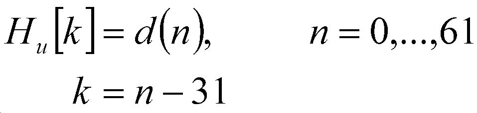
한 실시예에서, 시퀀스 ![]()
![]()

길이 62인 시퀀스 ![]()
![]()
시퀀스 ![]()
![]()
한 실시예에 따르면, 디스커버리 시퀀스는 PSS와 동일한 위치에서 사용되지만, 레거시 UE가 eNodeB 대신에 UE와 동기화하는 것을 피하기 위해서 다른 길이 및/또는 루트 인덱스를 갖는다. 한 실시예는 PSS를 위한 위치 매핑을 제공한다. 한 실시예는 하드웨어 설계, 표준화 작업 등을 단순화하기 위하여 기존 LTE 동기 설계와 함께 동작한다. 한 실시예는 또한 레거시 UE로 하여금 D2D UE가 사용되는 네트워크에서 계속하여 동작할 수 있도록 허용한다.According to one embodiment, the discovery sequence is used at the same location as the PSS, but has a different length and / or root index to avoid the legacy UE from synchronizing with the UE instead of the eNodeB. One embodiment provides location mapping for PSS. One embodiment works with existing LTE synchronous designs to simplify hardware design, standardization, and the like. One embodiment also allows the legacy UE to continue to operate in the network in which the D2D UE is used.
도 6은 여기서 설명된 장치 및 방법을 구현하기 위해 사용될 수 있는 프로세싱 시스템(600)의 블록도이다. 특정 장치가 도시도니 모든 구성요소를 사용할 수도 있고, 또는 구성요소의 서브세트 만을 사용할 수도 있으며, 통합 레벨은 장치 마다 매우 다를 수 있다. 6 is a block diagram of a
더 나아가, 장치는 복수의 프로세싱 유닛, 프로세서, 메모리, 송신기, 수신기, 등 다양한 구성요소의 예시를 담고 있을 수 있다. 프로세싱 시스템은 스피커, 마이크로폰, 마우스, 터치스크린, 키패드, 키보드, 프린터, 디스플레이, 기타 등등의 하나 또는 그 이상의 입력/출력 장치들이 갖춰진 프로세싱 유닛을 포함할 수 있다. 프로세싱 유닛은 중앙 처리 유닛(central processing unit, CPU), 메모리, 대용량 저장 장치, 비디오 어댑터, 그리고 버스에 연결된 I/O 인터페이스를 포함할 수 있다.Further, the apparatus may include examples of various components such as a plurality of processing units, processors, memories, transmitters, receivers, and the like. The processing system may include a processing unit equipped with one or more input / output devices such as a speaker, microphone, mouse, touch screen, keypad, keyboard, printer, display, The processing unit may include a central processing unit (CPU), a memory, a mass storage device, a video adapter, and an I / O interface coupled to the bus.
버스는, 메모리 버스 또는 메모리 컨트롤러(controller), 주변 버스(peripheral bus), 비디오 버스, 기타 등등을 포함하는 몇 가지 버스 아키텍처의 하나 또는 그 이상의 임의의 유형일 수 있다. CPU는 전자적 데이터 프로세서의 임의의 유형을 포함할 수 있다. 메모리는 정적 랜덤 액세스 메모리(static random access memory, SRAM), 동적 랜덤 액세스 메모리(dynamic random access memory, DRAM), 동기식 DRAM(synchronous DRAM, SDRAM), 읽기 전용 메모리(read-only memory, ROM), 그들의 조합, 기타 등등과 같은 시스템 메모리의 임의의 유형을 포함할 수 있다. 한 실시예에서, 메모리는 부트-업(boot-up)에서의 사용을 목적으로 ROM을 포함할 수 있고, 프로그램을 실행하는 동안의 사용을 목적으로 한 프로그램 및 데이터 저장소로서 DRAM을 포함할 수 있다.A bus may be any type of one or more of several bus architectures, including a memory bus or memory controller, a peripheral bus, a video bus, The CPU may include any type of electronic data processor. The memory may be a static random access memory (SRAM), a dynamic random access memory (DRAM), a synchronous DRAM (SDRAM), a read-only memory (ROM) Combinations, and so on. In one embodiment, the memory may include a ROM for purposes of use at boot-up, and may include a DRAM as a program and data store for use during execution of the program .
대용량 저장 장치는 데이터, 프로그램, 다른 정보를 저장하고, 버스를 거쳐서 데이터, 프로그램, 그리고 다른 정보에 접근할 수 있도록 구성된 저장 장치의 임의의 유형을 포함할 수 있다. 대용량 저장 장치는 예를 들어, 하나 또는 그 이상의 고체 상태 드라이브(solid state drive), 하드 디스크 드라이브(hard disk drive), 마그네틱 디스크 드라이브(magnetic disk drive), 광학 디스크 드라이브(optical disk drive), 기타 등등을 포함할 수 있다.A mass storage device may include any type of storage device configured to store data, programs, other information, and to access data, programs, and other information across the bus. A mass storage device may include, for example, one or more solid state drives, hard disk drives, magnetic disk drives, optical disk drives, etc. . ≪ / RTI >
비디오 어댑터 및 I/O 인터페이스는 외부의 입력 및 출력 장치를 프로세싱 유닛에 연결하는 인터페이스를 제공한다. 도시된 대로, 입력 및 출력 장치의 예시는 비디오 어댑터에 연결된 디스플레이, I/O 인터페이스에 연결된 마우스/키보드/프린터를 포함한다. 다른 장치는 프로세싱 유닛에 연결될 수 있고, 추가적인 또는 보다 소수의 인터페이스 카드가 사용될 수 있다. 예를 들어, 유니버설 직렬 버스(universal serial bus, USB)(미도시)와 같은 직렬 인터페이스가 프린터에게 인터페이스를 제공하기 위해서 사용될 수 있다.The video adapter and I / O interface provide an interface for connecting external input and output devices to the processing unit. As illustrated, examples of input and output devices include a display connected to a video adapter, a mouse / keyboard / printer connected to the I / O interface. Other devices may be coupled to the processing unit and additional or fewer interface cards may be used. For example, a serial interface such as a universal serial bus (USB) (not shown) may be used to provide an interface to the printer.
프로세싱 유닛은, 이더넷(Ethernet) 케이블 등과 같은 유선 링크(wired link), 및/또는 액세스 노드 또는 다른 네트워크로 향하는 무선 링크를 포함할 수 있는 하나 또는 그 이상의 네트워크 인터페이스를 포함한다. 네트워크 인터페이스는 프로세싱 유닛이 네트워크를 거쳐서 원격의 유닛들과 통신할 수 있도록 한다. 예를 들어, 네트워크 인터페이스는 하나 또는 그 이상의 송신기/송신 안테나 및 하나 또는 그 이상의 수신기/수신 안테나를 거쳐서 무선 통신을 제공할 수 있다. 한 실시예에서, 프로세싱 유닛은 다른 프로세싱 유닛, 인터넷, 원격 저장 시설, 기타 등등과 같은 원격 장치와 통신하고 데이터 프로세싱을 위해서 로컬 영역 네트워크(local-area network) 또는 광역 네트워크(wide-area network)와 연결된다.The processing unit includes one or more network interfaces that may include a wired link such as an Ethernet cable and / or a wireless link to an access node or other network. The network interface allows the processing unit to communicate with remote units over the network. For example, a network interface may provide wireless communication via one or more transmitter / transmit antennas and one or more receiver / receive antennas. In one embodiment, the processing unit communicates with a remote device, such as another processing unit, the Internet, a remote storage facility, etc., and communicates with a local-area network or a wide-area network .
도 7은 D2DSS를 사용하여 동기화하는 D2D 통신 장치에서 일어나는 동작(700) 실시예의 흐름도를 도시한다. 동작(700)은 상기 장치가 D2DSS를 사용하여 동기화하는 경우 D2D 통신 장치에서 일어나는 동작을 나타낼 수 있다.FIG. 7 shows a flow diagram of an
동작(700)은 D2D 통신 장치가 복수의 PRB를 수신하는 단계로부터 시작할 수 있다(블록 705). 복수의 PRB 내에 포함된 것은 PD2DSS일 수 있다. PD2DSS는 여기서 설명된 방법과 같은 기술을 사용하여 생성될 수 있다. PD2DSS는 SC-FDMA 파형에서 송신될 수 있다. 복수의 PRB는 또한 SD2DSS를 포함할 수 있다. SD2DSS는 여기서 설명된 방법과 같은 기술을 사용하여 생성될 수 있다. D2D 통신 장치는 PD2DSS를 탐지할 수 있다(710). D2D 통신 장치는 SD2DSS도 또한 탐지할 수 있다. D2D 통신 장치는 PD2DSS(그리고 잠재적으로는 SD2DSS)를 사용하여 동기화할 수 있다(블록 715).
도 8은 통신 장치(800)의 실시예를 도시한다. 통신 장치(800)는 D2D UE와 같은 D2D 동기 소스로서 동작하는 장치의 구현일 수 있다. 통신 장치(800)는 여기서 설명된 다양한 실시예를 구현하기 위해서 사용될 수 있다. 도 8에 도시된 대로, 송신기(805)는 패킷, D2DSS, PD2DSS, SD2DSS, 기타 등등을 송신하도록 구성된다. 통신 장치(800)는 또한 패킷 등을 수신하도록 구성된 수신기(810)를 포함한다.FIG. 8 shows an embodiment of a
시퀀스 선택 유닛(820)은 D2DSS를 얻기 위해 사용되는 시퀀스를 선택하도록 구성된다. 시퀀스 선택 유닛(820)은 ZC 시퀀스를 선택하도록 구성된다. 시퀀스 선택 유닛(820)은 DMRS, SRS 등과 같은, 통신 장치(800)의 상향링크에서 송신되는 다른 신호를 생성하기 위해 사용되는 시퀀스의 길이뿐만 아니라, LTE PSS를 생성하기 위해 사용되는 다른 ZC 시퀀스의 길이와 서로 다른 길이를 갖는 ZC 시퀀스를 선택하도록 구성된다. 시퀀스 선택 유닛(820)은 DMRS, SRS 등과 같은, 통신 장치(800)의 상향링크에서 송신되는 다른 신호를 생성하기 위해 사용되는 시퀀스의 루트 인덱스뿐만 아니라, LTE PSS를 생성하기 위해 사용되는 다른 ZC 시퀀스의 루트 인덱스와도 서로 다른 ZC 시퀀스의 루트 인덱스를 선택하도록 구성된다. 신호 생성 유닛(822)은 시퀀스 선택 유닛(820)에 의해 선택된 시퀀스에 따라서, D2DSS, PD2DSS, SD2DSS 등을 생성하도록 구성된다. 메모리(830)는 시퀀스, ZC 시퀀스, 길이, 루트 인덱스, 신호, 기타 등등을 저장하도록 구성된다. The sequence selection unit 820 is configured to select the sequence used to obtain the D2DSS. The sequence selection unit 820 is configured to select the ZC sequence. The sequence selection unit 820 may be configured to determine the length of a sequence used to generate another signal transmitted on the uplink of the
통신 장치(800)의 구성 요소는 특정 하드웨어 논리 블록(specific hardware logic blocks)으로서 구현될 수 있다. 또는, 통신 장치(800)의 구성 요소는 프로세서, 컨트롤러, 애플리케이션 특정 집적 회로, 기타 등등에서 실행하는 소프트웨어로서 구현될 수 있다. 또 다른 예로서, 통신 장치(800)의 구성 요소는 소프트웨어 및/또는 하드웨어의 조합으로서 구현될 수 있다.The components of the
한 실시예로서, 수신기(810) 및 송신기(805)는 특정 하드웨어 블록으로서 구현될 수 있는 한편, 시퀀스 선택 유닛(820) 및 신호 생성 유닛(822)은 마이크로프로세서(microprocessor)(프로세서(815)와 같은) 또는 맞춤형 회로 또는 필드 프로그래머블 논리 어레이(field programmable logic array)의 맞춤 충족 논리 어레이에서 실행하는 소프트웨어 모듈일 수 있다. 시퀀스 선택 유닛(820) 및 신호 생성 유닛(822)는 메모리(830)에 저장된 모듈일 수 있다.In one embodiment, the
비록 본 기재 및 그것의 유리한 점이 상세하게 설명되었지만, 다양한 변경, 치환 및 대체가, 부수된 클레임에 의해 정의된 대로의 개시 범위 및 사상에서 벗어나지 않고 만들어질 수 있다는 점이 이해되어야 한다.Although the present disclosure and its advantages have been described in detail, it should be understood that various changes, substitutions and alterations can be made herein without departing from the spirit and scope of the invention as defined by the appended claims.
Claims (28)
동기 소스(synchronization source)가, eNodeB(evolved NodeB)로부터 보내지는 주 동기 신호(primary synchronization signal, PSS) 및 장치대장치 통신 장치로부터 보내지는 기존 상향링크(uplink, UL) 신호와 서로 다른 주 장치대장치 동기 신호를 생성하는 단계; 그리고
상기 동기 소스가, 상기 주 장치대장치 동기 신호를 단일 캐리어 주파수 분할 다중 접속(single carrier frequency division multiple access, SC-FDMA) 파형으로 송신하는 단계
를 포함하는 장치대장치 통신 방법.A device-to-device communication method comprising:
A synchronization source may be configured to receive a primary synchronization signal (PSS) from an evolved NodeB (eNodeB) and an existing uplink (UL) signal sent from a device- Generating a device synchronization signal; And
The method of claim 1, wherein the synchronization source comprises: transmitting the master device-to-device synchronization signal to a single carrier frequency division multiple access (SC-FDMA)
To-device communication method.
상기 주 장치대장치 동기 신호를 생성하는 단계는,
제1 시퀀스에 따라서 동기 시퀀스를 생성하는 단계; 그리고
상기 주 장치대장치 동기 신호를 만들어 내기 위해서 상기 동기 시퀀스를 서브캐리어에 매핑하는 단계
를 포함하고,
여기서, 상기 제1 시퀀스의 제1 루트 인덱스는, 상기 PSS를 생성하기 위해 사용되는 제2 시퀀스의 제2 루트 인덱스 및 상기 기존 UL 신호를 생성하기 위해 사용되는 제3 시퀀스의 제3 루트 인덱스와 서로 다른, 장치대장치 통신 방법.The method according to claim 1,
Wherein the step of generating the master device-to-device synchronization signal comprises:
Generating a synchronization sequence in accordance with a first sequence; And
Mapping the synchronization sequence to a subcarrier to produce the master device-to-device synchronization signal
Lt; / RTI >
Here, the first route index of the first sequence is different from the second route index of the second sequence used to generate the PSS and the third route index of the third sequence used to generate the existing UL signal, Another, device-to-device communication method.
상기 제1 시퀀스는 제1 천공(punctured) 자도프-추(Zadoff-Chu, ZC) 시퀀스를 포함하고, 상기 제2 시퀀스는 제2 천공 ZC 시퀀스를 포함하는, 장치대장치 통신 방법.3. The method of claim 2,
Wherein the first sequence comprises a first punctured Zadoff-Chu (ZC) sequence and the second sequence comprises a second punctured ZC sequence.
상기 제1 천공 ZC 시퀀스와 상기 제2 천공 ZC 시퀀스가 동일한, 장치대장치 통신 방법.The method of claim 3,
Wherein the first puncturing ZC sequence and the second puncturing ZC sequence are the same.
상기 주 장치대장치 동기 신호를 매핑하는 단계는,
상기 주 장치대장치 동기 신호가 중심 대칭(centrally symmetric)이 될 수 있도록, 상기 동기 시퀀스를 상기 서브캐리어에 매핑하는 단계를 포함하는, 장치대장치 통신 방법.3. The method of claim 2,
Wherein mapping the master device-to-device synchronization signal comprises:
And mapping the synchronization sequence to the subcarrier such that the master device-to-device synchronization signal may be centrally symmetric.
상기 주 장치대장치 동기 신호의 N개의 샘플에 대해서, 상기 중심 대칭은 N이 정수 값인
For N samples of the master device-to-device sync signal, the center symmetry is such that N is an integer value
상기 동기 신호가

The synchronization signal
상기 동기 시퀀스는 아래와 같이 표현할 수 있고,

상기 동기 시퀀스는 아래에 따라서 매핑되며,

여기서 u는 상기 제1 루트 인덱스인, 장치대장치 통신 방법.8. The method of claim 7,
The synchronization sequence can be expressed as follows,
The synchronization sequence is mapped according to:
Where u is the first root index.
상기 제1 시퀀스 및 상기 제2 시퀀스의 길이가 다른, 장치대장치 통신 방법.3. The method of claim 2,
Wherein the first sequence and the second sequence have different lengths.
상기 제1 루트 인덱스가 상기 동기 소스의 식별자(identifier)에 따라서 선택되는, 장치대장치 통신 방법.3. The method of claim 2,
Wherein the first root index is selected according to an identifier of the synchronization source.
상기 제1 루트 인덱스가 상기 동기 소스의 유형에 따라서 선택되는, 장치대장치 통신 방법.3. The method of claim 2,
Wherein the first root index is selected according to the type of the synchronization source.
상기 주 장치대장치 동기 신호가 이산 푸리에 변환(discrete Fourier transform, DFT) 프리코딩 없이 송신되는, 장치대장치 통신 방법.The method according to claim 1,
Wherein the main device-to-device synchronization signal is transmitted without discrete Fourier transform (DFT) precoding.
상기 eNodeB에 의해 보내지는 제2 동기 신호를 생성하기 위해 사용되는 제5 시퀀스의 제2 길이 값과 다른 제1 길이 값을 갖는 제4 시퀀스에 따라서 제2 장치대장치 동기 신호를 생성하는 단계
를 더 포함하는 장치대장치 통신 방법.The method according to claim 1,
Generating a second device-to-device synchronization signal in accordance with a fourth sequence having a first length value different from a second length value of a fifth sequence used to generate a second synchronization signal sent by the eNodeB
To-device communication method.
상기 장치대장치 통신 장치가, eNodeB(evolved NodeB)로부터 보내지는 주 동기 신호(primary synchronization signal, PSS) 및 장치대장치 통신 장치로부터 보내지는 기존 상향링크(uplink, UL) 신호와 서로 다른 주 장치대장치 동기 신호를 포함하는 복수의 물리 자원 블록(physical resource block, PRB)을 수신하는 단계;
상기 장치대장치 통신 장치가, 상기 복수의 PRB 내에서 상기 주 장치대장치 동기 신호를 탐지하는 단계; 그리고
상기 장치대장치 통신 장치가, 상기 주 장치대장치 동기 신호에 따라서 동기화하는 단계
를 포함하고,
상기 주 장치대장치 동기 신호는 단일 캐리어 주파수 분할 다중 접속(single carrier frequency division multiple access, SC-FDMA) 파형으로 송신되는, 동작 방법.A method of operating a device-to-device communication device,
The device-to-device communication apparatus includes a primary synchronization signal (PSS) sent from an evolved NodeB (eNodeB) and an existing uplink (UL) signal sent from a device- A method comprising: receiving a plurality of physical resource blocks (PRB) including a device synchronization signal;
Wherein the device-to-device communication device comprises: detecting the master device-to-device synchronization signal within the plurality of PRBs; And
Wherein the device-to-device communication apparatus synchronizes in accordance with the master device-to-device synchronization signal
Lt; / RTI >
Wherein the main device-to-device synchronization signal is transmitted in a single carrier frequency division multiple access (SC-FDMA) waveform.
상기 주 장치대장치 동기 신호가 중심 대칭(centrally symmetric)인, 동작 방법.15. The method of claim 14,
Wherein the master device-to-device synchronization signal is centrally symmetric.
상기 주 장치대장치 동기 신호가 제1 시퀀스에 따라서 생성되고, 상기 제1 시퀀스의 제1 루트 인덱스는 상기 PSS를 생성하기 위해 사용되는 제2 시퀀스의 제2 루트 인덱스 및 상기 기존 UL 신호를 생성하기 위해 사용되는 제3 시퀀스의 제3 루트 인덱스와 서로 다른, 동작 방법.15. The method of claim 14,
Wherein the primary device-to-device synchronization signal is generated according to a first sequence, and wherein a first root index of the first sequence is used to generate a second root index of a second sequence used to generate the PSS, And the third root index of the third sequence used for the second sequence.
상기 제1 시퀀스는 제1 천공(punctured) 자도프-추(Zadoff-chu, ZC) 시퀀스를 포함하고, 상기 제2 시퀀스는 제2 천공 ZC 시퀀스를 포함하는, 동작 방법.17. The method of claim 16,
Wherein the first sequence comprises a first punctured Zadoff-chu (ZC) sequence and the second sequence comprises a second punctured ZC sequence.
상기 복수의 PRB는, 상기 eNodeB에 의해 보내지는 제2 동기 신호를 생성하기 위해 사용되는 제5 시퀀스의 제2 길이 값과 서로 다른 제1 길이 값을 갖는 제4 시퀀스에 따라서 생성된 제2 장치대장치 동기 신호를 더 포함하는, 동작 방법.15. The method of claim 14,
Wherein the plurality of PRBs comprises a plurality of PRBs, each of the plurality of PRBs being associated with a second device value generated in accordance with a fourth sequence having a first length value different from a second length value of a fifth sequence used to generate a second synchronization signal sent by the eNodeB Further comprising a device synchronization signal.
eNodeB(evolved NodeB)로부터 보내지는 주 동기 신호(primary synchronization signal, PSS) 및 장치대장치 통신 장치로부터 보내지는 기존 상향링크(uplink, UL) 신호와 서로 다른 주 장치대장치 동기 신호를 생성하도록 구성된 프로세서;
상기 주 장치대장치 동기 신호를 단일 캐리어 주파수 분할 다중 접속(single carrier frequency division multiple access, SC-FDMA) 파형으로 송신하도록 구성된, 상기 프로세서와 동작 가능하게 연결된 송신기
를 포함하는 동기 소스.As a synchronization source,
a processor configured to generate a primary synchronization signal (PSS) sent from an evolved NodeB (eNodeB) and a different primary device-to-device synchronization signal from an existing uplink (UL) signal sent from a device- ;
A transmitter operatively coupled to the processor and configured to transmit the master device-to-device synchronization signal to a single carrier frequency division multiple access (SC-FDMA) waveform;
/ RTI >
상기 프로세서는, 제1 시퀀스에 따라서 동기 시퀀스를 생성하도록 구성되고, 여기서 상기 제1 시퀀스의 제1 루트 인덱스는 상기 PSS를 생성하기 위해 사용되는 제2 시퀀스의 제2 루트 인덱스 및 상기 기존 UL 신호를 생성하기 위해 사용되는 제3 시퀀스의 제3 루트 인덱스와 서로 다르며, 상기 주 장치대장치 동기 신호를 만들어 내기 위해서 상기 동기 시퀀스를 서브캐리어에 매핑하도록 구성된, 동기 소스.20. The method of claim 19,
Wherein the processor is configured to generate a synchronization sequence in accordance with a first sequence, wherein a first route index of the first sequence is associated with a second route index of a second sequence used to generate the PSS, And to map the synchronization sequence to a subcarrier to produce the master device-to-device synchronization signal.
상기 동기 시퀀스는 아래와 같이 표현할 수 있고,

여기서 u는 상기 제1 루트 인덱스인, 동기 소스.21. The method of claim 20,
The synchronization sequence can be expressed as follows,
Where u is the first root index.
상기 제1 시퀀스는 제1 천공(punctured) 자도프-추(Zadoff-Chu, ZC) 시퀀스를 포함하고, 상기 제2 시퀀스는 제2 천공 ZC 시퀀스를 포함하는, 동기 소스.21. The method of claim 20,
Wherein the first sequence comprises a first punctured Zadoff-Chu (ZC) sequence and the second sequence comprises a second puncture ZC sequence.
상기 제1 천공 ZC 시퀀스와 상기 제2 천공 ZC 시퀀스가 동일한, 동기 소스.23. The method of claim 22,
Wherein the first puncture ZC sequence and the second puncture ZC sequence are the same.
상기 프로세서는, 상기 주 장치대장치 동기 신호가 중심 대칭(centrally symmetric)이 될 수 있도록 상기 동기 시퀀스를 상기 서브캐리어에 매핑하도록 구성된, 동기 소스.21. The method of claim 20,
Wherein the processor is configured to map the synchronization sequence to the subcarrier such that the master device-to-device synchronization signal may be centrally symmetric.
동기 소스(synchronization source)가,

상기 동기 소스가, 단일 캐리어 주파수 분할 다중 접속(single carrier frequency division multiple access, SC-FDMA) 파형으로 상기 주 장치대장치 동기 신호를 송신하는 단계
를 포함하고,
상기 주 장치대장치 동기 시퀀스가 H[]의 최대 N개의 푸리에 계수(Fourier coefficient)에 매핑되고, 여기서 Ts는 샘플링 주기(period)이고,
A synchronization source,
Wherein the synchronization source is configured to transmit the master device-to-device synchronization signal in a single carrier frequency division multiple access (SC-FDMA)
Lt; / RTI >
The main device-to-device synchronization sequence is mapped to a maximum of N Fourier coefficients of H [], where T s is a sampling period,
상기 푸리에 계수가 짝수 길이의 대칭 시퀀스로부터 획득되는, 장치대장치 통신 방법.26. The method of claim 25,
Wherein the Fourier coefficients are obtained from an even length symmetric sequence.
를 더 포함하는 장치대장치 통신 방법.26. The method of claim 25,
To-device communication method.
주파수
frequency
Applications Claiming Priority (5)
| Application Number | Priority Date | Filing Date | Title |
|---|---|---|---|
| US201361898973P | 2013-11-01 | 2013-11-01 | |
| US61/898,973 | 2013-11-01 | ||
| US14/530,322 US9615341B2 (en) | 2013-11-01 | 2014-10-31 | System and method for transmitting a synchronization signal |
| US14/530,322 | 2014-10-31 | ||
| PCT/US2014/063726 WO2015066632A1 (en) | 2013-11-01 | 2014-11-03 | System and method for transmitting a synchronization signal |
Related Child Applications (1)
| Application Number | Title | Priority Date | Filing Date |
|---|---|---|---|
| KR1020187019304A Division KR101993869B1 (en) | 2013-11-01 | 2014-11-03 | System and method for transmitting a synchronization signal |
Publications (1)
| Publication Number | Publication Date |
|---|---|
| KR20160078418A true KR20160078418A (en) | 2016-07-04 |
Family
ID=53005269
Family Applications (2)
| Application Number | Title | Priority Date | Filing Date |
|---|---|---|---|
| KR1020187019304A KR101993869B1 (en) | 2013-11-01 | 2014-11-03 | System and method for transmitting a synchronization signal |
| KR1020167013926A KR20160078418A (en) | 2013-11-01 | 2014-11-03 | System and method for transmitting a synchronization signal |
Family Applications Before (1)
| Application Number | Title | Priority Date | Filing Date |
|---|---|---|---|
| KR1020187019304A KR101993869B1 (en) | 2013-11-01 | 2014-11-03 | System and method for transmitting a synchronization signal |
Country Status (8)
| Country | Link |
|---|---|
| US (2) | US9615341B2 (en) |
| EP (2) | EP3063880B1 (en) |
| JP (1) | JP6308600B2 (en) |
| KR (2) | KR101993869B1 (en) |
| CN (3) | CN109714736B (en) |
| BR (1) | BR112016009796B1 (en) |
| RU (1) | RU2629165C1 (en) |
| WO (1) | WO2015066632A1 (en) |
Families Citing this family (34)
| Publication number | Priority date | Publication date | Assignee | Title |
|---|---|---|---|---|
| US10015828B2 (en) * | 2013-04-10 | 2018-07-03 | Telefonaktiebolaget L M Ericsson (Publ) | Method and wireless device for providing device-to-device communication |
| KR102061650B1 (en) * | 2013-04-30 | 2020-01-03 | 삼성전자주식회사 | A method and apparatus for synchronizaton of device to device communication in unlicensed bands |
| US9276693B2 (en) * | 2013-10-15 | 2016-03-01 | Electronics And Telecommunications Research Institute | Apparatus and method for transmitting synchronization signal |
| US9615341B2 (en) | 2013-11-01 | 2017-04-04 | Futurewei Technologies, Inc. | System and method for transmitting a synchronization signal |
| CN110365366B (en) * | 2013-11-01 | 2021-09-03 | 华为技术有限公司 | Transmitter, receiver and method of generating synchronization signal |
| US9967842B2 (en) * | 2013-11-11 | 2018-05-08 | Lg Electronics Inc. | Method for detecting synchronization signal for device-to-device (D2D) communication in wireless communication system and apparatus therefor |
| EP3099123B1 (en) | 2014-01-26 | 2019-11-13 | LG Electronics Inc. | Method for transmitting synchronization signal and synchronization channel in wireless communication system supporting device-to-device communication and apparatus for same |
| US9609503B2 (en) * | 2014-01-28 | 2017-03-28 | Samsung Electronics Co., Ltd | Method and device for detecting and generating synchronization signal for device-to-device wireless communication |
| US20170006563A1 (en) * | 2014-01-31 | 2017-01-05 | Telefonaktiebolaget Lm Ericsson (Publ) | Monitoring Synchronization Signals in Device-to-Device Communication |
| US10263825B2 (en) * | 2014-02-05 | 2019-04-16 | Lg Electronics Inc. | Method and device for transmitting synchronization signal for D2D (device to device) communication in wireless communication system |
| WO2015122715A1 (en) | 2014-02-13 | 2015-08-20 | 엘지전자 주식회사 | Method for transmitting/receiving synchronization signal for d2d communication in wireless communication system, and apparatus therefor |
| US10862634B2 (en) | 2014-03-07 | 2020-12-08 | Huawei Technologies Co., Ltd. | Systems and methods for OFDM with flexible sub-carrier spacing and symbol duration |
| KR102247142B1 (en) * | 2014-05-09 | 2021-05-04 | 삼성전자주식회사 | Method and apparatus for transmitting synchronization signals in device-to-device communication |
| KR102423501B1 (en) * | 2014-05-09 | 2022-07-21 | 엘지전자 주식회사 | Method for transmitting synchronization signal for direct communication between terminals in wireless communication system, and apparatus therefor |
| CN106664674B (en) * | 2014-10-07 | 2020-03-24 | Lg 电子株式会社 | Method for transmitting synchronization signal for device-to-device communication in wireless communication system and apparatus therefor |
| CN107534946B (en) * | 2015-04-30 | 2020-09-04 | 瑞典爱立信有限公司 | Method for use in a radio node and associated radio node |
| CN106303900B (en) * | 2015-05-15 | 2020-10-30 | 索尼公司 | Wireless communication apparatus and wireless communication method |
| WO2017070944A1 (en) | 2015-10-30 | 2017-05-04 | 华为技术有限公司 | Signal sending device and receiving device, and method and system for symbol timing synchronization |
| JP6816857B2 (en) | 2016-01-20 | 2021-01-20 | ホアウェイ・テクノロジーズ・カンパニー・リミテッド | Synchronous information transmission method and device |
| KR101860205B1 (en) * | 2016-06-29 | 2018-05-23 | 한국과학기술원 | Apparatus and method for communicating through random access |
| EP3520275A1 (en) | 2016-09-30 | 2019-08-07 | Sony Mobile Communications Inc. | Subcarrier spacing selection for synchronization signals |
| US10448364B2 (en) * | 2017-01-19 | 2019-10-15 | Qualcomm Incorporated | Methods and apparatus related to time tracking in multi carrier systems |
| WO2018160036A1 (en) * | 2017-03-02 | 2018-09-07 | 엘지전자 주식회사 | Method and apparatus for transmitting sidelink signal in wireless communication system |
| US11368344B2 (en) * | 2017-03-15 | 2022-06-21 | Motorola Mobility Llc | Method and apparatus having a synchronization signal sequence structure for low complexity cell detection |
| US10680866B2 (en) * | 2017-03-24 | 2020-06-09 | Huawei Technologies Co., Ltd. | Sounding reference signal design |
| WO2018203627A1 (en) * | 2017-05-02 | 2018-11-08 | 엘지전자(주) | Method for transmitting and receiving signals in wireless communication system and device therefor |
| US11051263B2 (en) * | 2017-06-15 | 2021-06-29 | Qualcomm Incorporated | Synchronization channel and system acquisition for internet of things communications in a shared spectrum |
| CN115102662A (en) * | 2017-06-16 | 2022-09-23 | 摩托罗拉移动有限责任公司 | Method and apparatus for establishing a set of multiple synchronization signal sequences for use with one or more communication targets |
| CN109842478A (en) * | 2017-11-26 | 2019-06-04 | 华为技术有限公司 | A kind of sequence determines method and apparatus |
| US10439779B2 (en) | 2017-11-26 | 2019-10-08 | Huawei Technologies Co., Ltd. | Sequence determining method and apparatus |
| CN111052816A (en) | 2018-02-09 | 2020-04-21 | Oppo广东移动通信有限公司 | Method, apparatus and computer storage medium for transmitting synchronization signal |
| CN110492969B (en) * | 2018-05-11 | 2022-04-29 | 中兴通讯股份有限公司 | Signal transmitting and receiving method and device |
| US11696241B2 (en) * | 2019-07-30 | 2023-07-04 | Qualcomm Incorporated | Techniques for synchronizing based on sidelink synchronization signal prioritization |
| CN112422218B (en) * | 2019-08-21 | 2022-09-09 | 华为技术有限公司 | Synchronization signal transmission method and communication device |
Family Cites Families (52)
| Publication number | Priority date | Publication date | Assignee | Title |
|---|---|---|---|---|
| US8170081B2 (en) * | 2004-04-02 | 2012-05-01 | Rearden, LLC. | System and method for adjusting DIDO interference cancellation based on signal strength measurements |
| DE602006016492D1 (en) * | 2006-01-18 | 2010-10-07 | Huawei Tech Co Ltd | ORMATION TRANSMISSION IN A COMMUNICATION SYSTEM |
| US9462564B2 (en) | 2006-05-01 | 2016-10-04 | Nokia Technologies Oy | Apparatus, method and computer program product providing uplink synchronization through use of dedicated uplink resource assignment |
| US7756198B2 (en) | 2006-08-18 | 2010-07-13 | Fujitsu Limited | System and method for assigning channels in a wireless network |
| CN101641874B (en) | 2006-08-18 | 2013-11-06 | 富士通株式会社 | New and legacy wireless communication device coexisting amble sequence |
| GB2458418B (en) | 2006-12-19 | 2011-08-03 | Lg Electronics Inc | Sequence generating method for efficient detection and method for transmitting and receiving signals using the same |
| CN101573899B (en) | 2007-01-08 | 2013-01-23 | Lm爱立信电话有限公司 | Secondary synchronization sequences for cell group detection in a cellular communications system |
| DK2090050T4 (en) | 2007-05-02 | 2017-09-25 | Huawei Tech Co Ltd | Method of establishing a synchronization signal in a communication system. |
| US8223908B2 (en) | 2007-05-02 | 2012-07-17 | Qualcomm Incorporated | Selection of acquisition sequences for optimal frequency offset estimation |
| US8014424B2 (en) * | 2007-06-25 | 2011-09-06 | Qualcomm Incorporated | Method and apparatus for using an unique index set for PSC sequence in a wireless communication system |
| CN101502018B (en) * | 2007-08-15 | 2013-06-05 | 华为技术有限公司 | Generation and detection of synchronization signals |
| CN101136696B (en) * | 2007-09-27 | 2012-11-14 | 中兴通讯股份有限公司 | Method to generate single carrier frequency division multiple address signal of uplink sharing channel |
| KR101599844B1 (en) | 2007-12-24 | 2016-03-04 | 엘지전자 주식회사 | Method of Multiplexing Multiple Access Region |
| EP2340681B1 (en) | 2008-09-25 | 2014-11-12 | Nokia Corporation | Synchronization for device-to-device communication |
| EP2202933B1 (en) | 2008-12-23 | 2016-10-26 | Telefonaktiebolaget LM Ericsson (publ) | Technique for generating an sc-fdma signal |
| WO2010110568A2 (en) | 2009-03-22 | 2010-09-30 | 엘지전자 주식회사 | Channel-sounding method using a plurality of antennas, and apparatus for same |
| CN102111758A (en) * | 2009-12-28 | 2011-06-29 | 北京安码科技有限公司 | Method for solving end-to-end problem in mobile communication based on encryption system |
| US8792433B2 (en) | 2010-05-11 | 2014-07-29 | Qualcomm Incorporated | Hardware implementation of uplink receiver with matched throughput |
| US9420570B2 (en) | 2010-07-26 | 2016-08-16 | Lg Electronics Inc. | Method and device for transmitting an uplink control signal in a wireless communication system |
| WO2013002688A1 (en) * | 2011-06-29 | 2013-01-03 | Telefonaktiebolaget L M Ericsson (Publ) | A method and a user equipment for peer-to-peer communication |
| KR101427072B1 (en) | 2011-07-27 | 2014-08-05 | 엘지전자 주식회사 | Method for transmitting an uplink reference signal in a multi-node system and terminal using same |
| US9414337B2 (en) | 2011-08-23 | 2016-08-09 | Lg Electronics Inc. | Method for transmitting and receiving synchronization signals in wireless access system and apparatus therefor |
| CN103108405B (en) * | 2011-11-15 | 2017-09-08 | 中兴通讯股份有限公司 | Wireless communications method and system |
| CN103108389A (en) * | 2011-11-15 | 2013-05-15 | 中兴通讯股份有限公司 | Communication method and communication system from device to device and user devices |
| WO2013077684A1 (en) * | 2011-11-24 | 2013-05-30 | 엘지전자 주식회사 | Method for performing device-to-device communication in wireless access system and apparatus for same |
| US20140342747A1 (en) * | 2012-01-18 | 2014-11-20 | Lg Electronics Inc. | Device-to-device communication method and a device therefor |
| US9521644B2 (en) * | 2012-01-31 | 2016-12-13 | Qualcomm Incorporated | Methods and apparatus for providing network-assisted end-to-end paging between LTE devices |
| US9325555B2 (en) | 2012-02-24 | 2016-04-26 | Lg Electronics Inc. | Method and device for tracking synchronization |
| WO2013125887A1 (en) | 2012-02-24 | 2013-08-29 | 엘지전자 주식회사 | Transmission method and transmission device |
| US9258692B2 (en) * | 2012-03-30 | 2016-02-09 | Qualcomm Incorporated | Relay assisted peer discovery |
| CN103379617B (en) * | 2012-04-26 | 2016-08-10 | 华为技术有限公司 | A kind of subscriber equipment is to the communication means of subscriber equipment and subscriber equipment |
| US9002281B2 (en) | 2012-04-30 | 2015-04-07 | Intel Corporation | Apparatus and method to enable device-to-device (D2D) communication in cellular networks |
| TWI532352B (en) * | 2012-05-04 | 2016-05-01 | 財團法人資訊工業策進會 | Evolved packet core less direct mode communication system and communication attaching method thereof |
| CN102769868B (en) * | 2012-07-23 | 2014-10-29 | 西安电子科技大学 | M2M (Machine to Machine) service wireless resource dispatching method based on TD-SCDMA (Time Division-Synchronous Code Division Multiple Access) network |
| CN102780993B (en) * | 2012-08-20 | 2015-04-15 | 哈尔滨工业大学 | Terminal D2D (device-to-device) cooperation relay communication implementation method in TD-LTE-A (time division-long term evolution-advanced) system |
| US9451570B2 (en) * | 2012-08-29 | 2016-09-20 | Alcatel Lucent | Device discovery for device-to-device communication |
| US8923464B2 (en) * | 2012-11-16 | 2014-12-30 | Qualcomm Incorporated | Methods and apparatus for enabling distributed frequency synchronization |
| US9185697B2 (en) * | 2012-12-27 | 2015-11-10 | Google Technology Holdings LLC | Method and apparatus for device-to-device communication |
| JP2016519478A (en) * | 2013-04-02 | 2016-06-30 | エルジー エレクトロニクス インコーポレイティド | Discovery signal transmission method and apparatus for direct communication between terminals in wireless communication system |
| KR102243662B1 (en) * | 2013-09-01 | 2021-04-23 | 엘지전자 주식회사 | Method for transmitting sync signals for device-to-device (d2d) communication in wireless communication system and apparatus therefor |
| KR102210635B1 (en) * | 2013-09-27 | 2021-02-02 | 엘지전자 주식회사 | Method for synchronization between user equipment for device-to-device (d2d) communication in wireless communication system and apparatus for same |
| CN103595679B (en) * | 2013-10-27 | 2016-05-25 | 西安电子科技大学 | Reduce the method for LTE uplink single-carrier frequency division multiple address signal peak-to-average force ratio |
| KR102238537B1 (en) * | 2013-10-28 | 2021-04-09 | 엘지전자 주식회사 | Method and apparatus for transmitting and receiving signal for device-to-device terminal in wireless communication system |
| EP3063914B1 (en) * | 2013-10-31 | 2019-04-03 | Huawei Technologies Co., Ltd. | System and method for device-to-device synchronization |
| US9615341B2 (en) | 2013-11-01 | 2017-04-04 | Futurewei Technologies, Inc. | System and method for transmitting a synchronization signal |
| CN110365366B (en) * | 2013-11-01 | 2021-09-03 | 华为技术有限公司 | Transmitter, receiver and method of generating synchronization signal |
| US9609503B2 (en) | 2014-01-28 | 2017-03-28 | Samsung Electronics Co., Ltd | Method and device for detecting and generating synchronization signal for device-to-device wireless communication |
| US10263825B2 (en) | 2014-02-05 | 2019-04-16 | Lg Electronics Inc. | Method and device for transmitting synchronization signal for D2D (device to device) communication in wireless communication system |
| US10244493B2 (en) | 2014-08-26 | 2019-03-26 | Lg Electronics Inc. | Method for transmitting and receiving synchronization signal in wireless communication system and device for performing same |
| WO2016034106A1 (en) | 2014-09-04 | 2016-03-10 | Huawei Technologies Co., Ltd. | System and method for communicating resource allocation for d2d |
| KR101901950B1 (en) | 2014-09-05 | 2018-09-28 | 엘지전자 주식회사 | Method for performing communication between devices in wireless communication system and device for performing same |
| US9439039B1 (en) | 2015-08-06 | 2016-09-06 | Qualcomm Incorporated | Device-to-device ranging and positioning |
-
2014
- 2014-10-31 US US14/530,322 patent/US9615341B2/en active Active
- 2014-11-03 EP EP14857687.9A patent/EP3063880B1/en active Active
- 2014-11-03 WO PCT/US2014/063726 patent/WO2015066632A1/en active Application Filing
- 2014-11-03 JP JP2016527423A patent/JP6308600B2/en active Active
- 2014-11-03 RU RU2016121479A patent/RU2629165C1/en active
- 2014-11-03 BR BR112016009796-3A patent/BR112016009796B1/en active IP Right Grant
- 2014-11-03 CN CN201910107386.9A patent/CN109714736B/en active Active
- 2014-11-03 CN CN201480058761.0A patent/CN105684324B/en active Active
- 2014-11-03 EP EP18183080.3A patent/EP3404882A1/en active Pending
- 2014-11-03 CN CN201910107427.4A patent/CN109831269B/en active Active
- 2014-11-03 KR KR1020187019304A patent/KR101993869B1/en active IP Right Grant
- 2014-11-03 KR KR1020167013926A patent/KR20160078418A/en active Application Filing
-
2017
- 2017-01-11 US US15/403,892 patent/US10306573B2/en active Active
Also Published As
| Publication number | Publication date |
|---|---|
| CN105684324A (en) | 2016-06-15 |
| US20170127365A1 (en) | 2017-05-04 |
| RU2629165C1 (en) | 2017-08-24 |
| CN109714736A (en) | 2019-05-03 |
| CN109714736B (en) | 2021-09-07 |
| US9615341B2 (en) | 2017-04-04 |
| KR101993869B1 (en) | 2019-06-27 |
| JP6308600B2 (en) | 2018-04-11 |
| CN109831269A (en) | 2019-05-31 |
| US10306573B2 (en) | 2019-05-28 |
| BR112016009796A2 (en) | 2017-08-01 |
| EP3063880A4 (en) | 2017-02-15 |
| CN105684324B (en) | 2019-03-01 |
| KR20180080373A (en) | 2018-07-11 |
| JP2016538777A (en) | 2016-12-08 |
| EP3404882A1 (en) | 2018-11-21 |
| EP3063880B1 (en) | 2018-09-05 |
| WO2015066632A1 (en) | 2015-05-07 |
| EP3063880A1 (en) | 2016-09-07 |
| US20150124579A1 (en) | 2015-05-07 |
| BR112016009796B1 (en) | 2023-04-11 |
| CN109831269B (en) | 2020-06-16 |
Similar Documents
| Publication | Publication Date | Title |
|---|---|---|
| KR101993869B1 (en) | System and method for transmitting a synchronization signal | |
| US11916813B2 (en) | Method and device for indicating sub-band configuration, and method and device for accessing sub-band | |
| US11122530B2 (en) | Method and apparatus of synchronizing device to device terminals in time and frequency | |
| US11259259B2 (en) | Transmitter, receiver and methods for transmitting/ receiving synchronisation signals | |
| RU2638030C1 (en) | Method and device for device-device communication synchronization | |
| US10034253B2 (en) | Cell search procedure frame format | |
| EP3493621B1 (en) | Terminal device, communication method and integrated circuit | |
| US20160337101A1 (en) | Signal transmission method and signal transmission apparatus | |
| US20230007603A1 (en) | Methods for enabling a reduced bandwidth wireless device to access a cell | |
| WO2017133676A1 (en) | Method and device for transmitting and receiving reference signal, and transmission system | |
| WO2020032645A1 (en) | Method and device for indicating synchronization signal block in wireless communication system | |
| US20220394776A1 (en) | Wireless device, a network node, and methods therein for determining an identity of a wireless device during a random access procedure | |
| JP7306568B2 (en) | Communication method | |
| JP2014138319A (en) | Base station device, terminal device, communication system and communication method |
Legal Events
| Date | Code | Title | Description |
|---|---|---|---|
| A201 | Request for examination | ||
| AMND | Amendment | ||
| E902 | Notification of reason for refusal | ||
| AMND | Amendment | ||
| E601 | Decision to refuse application | ||
| AMND | Amendment | ||
| A107 | Divisional application of patent | ||
| J201 | Request for trial against refusal decision | ||
| J301 | Trial decision |
Free format text: TRIAL NUMBER: 2018101002877; TRIAL DECISION FOR APPEAL AGAINST DECISION TO DECLINE REFUSAL REQUESTED 20180705 Effective date: 20191121 |