EP3063880B1 - System and method for transmitting a synchronization signal - Google Patents
System and method for transmitting a synchronization signal Download PDFInfo
- Publication number
- EP3063880B1 EP3063880B1 EP14857687.9A EP14857687A EP3063880B1 EP 3063880 B1 EP3063880 B1 EP 3063880B1 EP 14857687 A EP14857687 A EP 14857687A EP 3063880 B1 EP3063880 B1 EP 3063880B1
- Authority
- EP
- European Patent Office
- Prior art keywords
- sequence
- synchronization
- synchronization signal
- primary
- root index
- Prior art date
- Legal status (The legal status is an assumption and is not a legal conclusion. Google has not performed a legal analysis and makes no representation as to the accuracy of the status listed.)
- Active
Links
- 238000000034 method Methods 0.000 title claims description 31
- 238000004891 communication Methods 0.000 claims description 65
- 238000013507 mapping Methods 0.000 claims description 7
- 238000005070 sampling Methods 0.000 claims description 5
- 101150071746 Pbsn gene Proteins 0.000 claims 4
- 238000012545 processing Methods 0.000 description 13
- 230000015654 memory Effects 0.000 description 10
- 238000010586 diagram Methods 0.000 description 9
- 238000013461 design Methods 0.000 description 6
- 230000008901 benefit Effects 0.000 description 4
- 230000001413 cellular effect Effects 0.000 description 3
- 238000001514 detection method Methods 0.000 description 3
- 230000005540 biological transmission Effects 0.000 description 2
- 125000004122 cyclic group Chemical group 0.000 description 2
- 238000001228 spectrum Methods 0.000 description 2
- 230000004075 alteration Effects 0.000 description 1
- 230000010267 cellular communication Effects 0.000 description 1
- 238000013500 data storage Methods 0.000 description 1
- 230000001419 dependent effect Effects 0.000 description 1
- 238000005516 engineering process Methods 0.000 description 1
- 238000001914 filtration Methods 0.000 description 1
- 230000007274 generation of a signal involved in cell-cell signaling Effects 0.000 description 1
- 230000010354 integration Effects 0.000 description 1
- 230000007774 longterm Effects 0.000 description 1
- 230000007246 mechanism Effects 0.000 description 1
- 230000003287 optical effect Effects 0.000 description 1
- 230000002093 peripheral effect Effects 0.000 description 1
- 230000008569 process Effects 0.000 description 1
- 230000009467 reduction Effects 0.000 description 1
- 230000011664 signaling Effects 0.000 description 1
- 239000007787 solid Substances 0.000 description 1
- 230000003068 static effect Effects 0.000 description 1
- 238000006467 substitution reaction Methods 0.000 description 1
- 230000001360 synchronised effect Effects 0.000 description 1
- 230000009466 transformation Effects 0.000 description 1
Images


Classifications
-
- H—ELECTRICITY
- H04—ELECTRIC COMMUNICATION TECHNIQUE
- H04B—TRANSMISSION
- H04B7/00—Radio transmission systems, i.e. using radiation field
- H04B7/14—Relay systems
- H04B7/15—Active relay systems
- H04B7/204—Multiple access
- H04B7/212—Time-division multiple access [TDMA]
-
- H—ELECTRICITY
- H04—ELECTRIC COMMUNICATION TECHNIQUE
- H04J—MULTIPLEX COMMUNICATION
- H04J11/00—Orthogonal multiplex systems, e.g. using WALSH codes
- H04J11/0069—Cell search, i.e. determining cell identity [cell-ID]
- H04J11/0073—Acquisition of primary synchronisation channel, e.g. detection of cell-ID within cell-ID group
-
- H—ELECTRICITY
- H04—ELECTRIC COMMUNICATION TECHNIQUE
- H04W—WIRELESS COMMUNICATION NETWORKS
- H04W56/00—Synchronisation arrangements
- H04W56/001—Synchronization between nodes
-
- H—ELECTRICITY
- H04—ELECTRIC COMMUNICATION TECHNIQUE
- H04J—MULTIPLEX COMMUNICATION
- H04J11/00—Orthogonal multiplex systems, e.g. using WALSH codes
-
- H—ELECTRICITY
- H04—ELECTRIC COMMUNICATION TECHNIQUE
- H04W—WIRELESS COMMUNICATION NETWORKS
- H04W4/00—Services specially adapted for wireless communication networks; Facilities therefor
- H04W4/70—Services for machine-to-machine communication [M2M] or machine type communication [MTC]
-
- H—ELECTRICITY
- H04—ELECTRIC COMMUNICATION TECHNIQUE
- H04W—WIRELESS COMMUNICATION NETWORKS
- H04W72/00—Local resource management
- H04W72/20—Control channels or signalling for resource management
- H04W72/21—Control channels or signalling for resource management in the uplink direction of a wireless link, i.e. towards the network
-
- H—ELECTRICITY
- H04—ELECTRIC COMMUNICATION TECHNIQUE
- H04J—MULTIPLEX COMMUNICATION
- H04J11/00—Orthogonal multiplex systems, e.g. using WALSH codes
- H04J2011/0096—Network synchronisation
-
- H—ELECTRICITY
- H04—ELECTRIC COMMUNICATION TECHNIQUE
- H04J—MULTIPLEX COMMUNICATION
- H04J2211/00—Orthogonal indexing scheme relating to orthogonal multiplex systems
- H04J2211/003—Orthogonal indexing scheme relating to orthogonal multiplex systems within particular systems or standards
- H04J2211/005—Long term evolution [LTE]
-
- H—ELECTRICITY
- H04—ELECTRIC COMMUNICATION TECHNIQUE
- H04W—WIRELESS COMMUNICATION NETWORKS
- H04W88/00—Devices specially adapted for wireless communication networks, e.g. terminals, base stations or access point devices
- H04W88/08—Access point devices
Definitions
- the present invention relates to wireless communications, and, in particular embodiments, to a system and method for transmitting a synchronization signal.
- D2D Device-to-Device
- D2D transmitting and receiving user equipments should acquire the same time and/or frequency synchronization from synchronization source(s). These sources need to periodically transmit at least a D2D synchronization signal (D2DSS) to ensure D2D UEs derive time and/or frequency synchronization.
- D2DSS D2D synchronization signal
- the synchronization source could be a base station, an evolved NodeB (eNodeB) (like a traditional Third Generation Partnership Project (3GPP) Long Term Evolution (LTE) network), or a D2D UE which is relaying the downlink (DL) synchronization channel from an eNodeB.
- eNodeB evolved NodeB
- 3GPP Third Generation Partnership Project
- LTE Long Term Evolution
- D2D UE which is relaying the downlink (DL) synchronization channel from an eNodeB.
- 3GPP DRAFT; WF ON THE D2D SYNCHRONIZATION PROCEDURE V8 refers to methods of in coverage synchronization and out of coverage synchronization.
- some in-coverage UEs transmit D2DSS based on their synchronization to an eNodeB.
- UEs can synchronize to the D2DSS transmitted by UEs in another cell for neighbor-cell discovery and communication.
- Example embodiments of the present disclosure provide a system and method for transmitting a synchronization signal which aim at ensuring a fine time and frequency synchronization of the D2D UE.
- Claim 1 and Claim 10 state a solution to this object. Further advantageous embodiments and improvements of the invention are listed in the dependent claims. Hereinafter, some examples and aspects of the invention are highlighted before coming to a detailed discussion of the embodiments of the invention.
- a method for device-to-device communications includes generating, by a synchronization source, a primary device-to-device synchronization signal that is different from a primary synchronization signal (PSS) sent by an Evolved NodeB (eNodeB) and is different from an existing uplink (UL) signal sent by device-to-device communications devices, and transmitting, by the synchronization source, the primary device-to-device synchronization signal in a single carrier frequency division multiple access (SC-FDMA) waveform, wherein generating the primary device-to-device synchronization signal comprises: generating a synchronization sequence in accordance with a first sequence, wherein a first root index of the first sequence is different from a second root index of a second sequence used to generate the PSS; and mapping the synchronization sequence onto subcarriers to produce the primary device-to-device synchronization signal.
- PSS primary synchronization signal
- eNodeB Evolved NodeB
- UL uplink
- a method of operating a device-to-device communications device includes receiving, by the device-to-device communications device, a plurality of physical resource blocks (PRBs) including a primary device-to-device synchronization signal that is different from a primary synchronization signal (PSS) sent by an Evolved NodeB (eNodeB) and is different from an existing uplink (UL) signal sent by device-to-device communications devices, wherein the primary device-to-device synchronization signal is transmitted in a single carrier frequency division multiple access (SC-FDMA) waveform, wherein the primary device-to-device synchronization signal is generated from a synchronization sequence in accordance with a first sequence, wherein a first root index of the first sequence is different from a second root index of a second sequence used to generate the PSS.
- PRBs physical resource blocks
- the method also includes detecting, by the device-to-device communications device, the primary device-to-device synchronization signal in the plurality of PRBs, and synchronizing, by the device-to-device communications device, in accordance with the primary device-to-device synchronization signal.
- a synchronization source includes a processor, and a transmitter operatively coupled to the processor.
- the processor generates a primary device-to-device synchronization signal that is different from a primary synchronization signal (PSS) sent by an Evolved NodeB (eNodeB) and an existing uplink (UL) signal sent by device-to-device communications devices.
- PSS primary synchronization signal
- eNodeB Evolved NodeB
- UL uplink
- the transmitter transmits the primary device-to-device synchronization signal in a single carrier frequency division multiple access (SC-FDMA) waveform.
- SC-FDMA single carrier frequency division multiple access
- the method also includes transmitting, by the synchronization source, the primary device-to-device synchronization signal in a single carrier frequency division multiple access (SC-FDMA) waveform.
- SC-FDMA single carrier frequency division multiple access
- One advantage of an embodiment is that the use of centrally symmetric signals simplifies decoding complexity.
- the present disclosure will be described with respect to example embodiments in a specific context, namely communications systems that use a synchronization signal to facilitate D2D communications.
- the disclosure may be applied to standards compliant communications systems, such as those that are compliant with Third Generation Partnership Project (3GPP), IEEE 802.11, and the like, technical standards, and non-standards compliant communications systems, that use a synchronization signal to facilitate D2D communications.
- 3GPP Third Generation Partnership Project
- IEEE 802.11 IEEE 802.11
- non-standards compliant communications systems that use a synchronization signal to facilitate D2D communications.
- FIG. 1 illustrates an example communications system 100.
- Communications system 100 supports D2D communications and may therefore be referred to as a D2D system.
- D2D synchronization in a D2D system is highlighted in Figure 1 .
- D2DUE1 105, D2DUE2 110, and D2DUE3 115 may derive time and/or frequency synchronization based on legacy LTE DL synchronization channel, such as primary synchronization signal (PSS) and secondary synchronization signal (SSS), sent by eNodeB 120, or other synchronization signals sent by eNodeB 120.
- PSS primary synchronization signal
- SSS secondary synchronization signal
- D2DUE3 115 and D2DUE5 125 also play the role of synchronization sources (i.e., D2D synchronization sources) for D2DUE4 130 and D2DUE6 135, respectively.
- eNodeBs may also be commonly referred to as NodeBs, controllers, base stations, access points, base terminal stations, and the like.
- UEs may also be commonly referred to as mobile stations, mobiles, terminals, users, stations, subscribers, and the like. While it is understood that communications systems may employ multiple eNodeBs capable of communicating with a number of UEs, only one eNodeB, and a number of UEs are illustrated for simplicity.
- Discovery is a D2D technique that includes the ability to discover neighboring UEs.
- Discovery can be either eNodeB-assisted discovery or open discovery.
- eNodeB-assisted discovery a first UE is directed to transmit a signal (e.g., a sounding reference signal (SRS)), and a second UE is required to listen and report the signal quality to the eNodeB.
- the eNodeB may, based on this reported signal quality, decide if ProSe can be enabled for these two UEs.
- SRS sounding reference signal
- any UE may transmit a signal, such as a beacon signal, to advertise its presence to other UEs. It is noted that this process can possibly involve idle UEs.
- open discovery may involve idle UEs, it is typically performed with very limited available information.
- the UEs typically have to rely on the information broadcasted by the eNodeB. It may be too costly in most situations to wake up these UEs and transmit radio resource control (RRC) signaling to them.
- RRC radio resource control
- the location of idle UEs is approximate, and the exact cell where the UEs are camping is not known by the communications system.
- D2D occurs on the uplink (UL) portion of the bandwidth since the interference would be less prejudicial to cellular UEs on the UL.
- UL uplink
- a transmitting D2D UE interferes with the eNodeB. Consequently, as long as the D2D UE is at a reasonable distance from the eNodeB, the interference created by the D2D UE has little impact.
- D2D interference affects neighboring UEs, and potentially their ability to receive synchronization channels and PDCCH is affected, and can result in significantly higher impact than if the D2D UE were transmitting on the UL.
- FIG. 2 illustrates example subframes 200. Some of the subframes 200 are used as discovery subframes (shown as cross-hatched boxes), while others are used as cellular subframes (shown as unshaded boxes).
- example D2D synchronization signals are provided.
- the design principles of D2DSS may include one or more of the following:
- a legacy UE should not be able to detect the D2DSS, which would prevent the legacy UE from mistakenly assuming that a D2D UE (source of the D2DSS) is an eNodeB. It is noted that the example embodiments described herein can be combined.
- the detection of a D2DSS typically encompasses some form of matched filtering in the receiver, e.g., determining a correlation between the received signal and the D2DSS. Since this involves performing large amounts of complex-valued multiplications, it is an objective to design the D2DSS such that it exhibits signal properties which may be used for reducing the detection complexity.
- Figure 3 illustrates a flow diagram of example operations 300 occurring in a D2D UE.
- Operations 300 may be indicative of operations occurring in a D2D UE.
- Operations 300 may begin with the D2D UE generating a D2DSS (block 305).
- the D2D UE may generate a sequence for the D2DSS (e.g., a PD2DSS and/or a SD2DSS). Details of example embodiments of D2DSS are presented below.
- the D2D UE may map the sequence of the D2DSS, producing a mapped D2DSS (block 310).
- the D2D UE may map the sequence of the D2DSS to subcarriers so that the D2DSS is centrally symmetric, for example.
- the D2D UE may transmit the mapped D2DSS (block 315). As discussed previously, the mapped D2DSS may be transmitted in UL resources or subframes.
- a D2DSS is based on a ZC sequence with a length that differs from the length of other ZC sequences used in the communications system.
- a synchronization source transmits a D2DSS based on which a group of D2D UEs (making up a D2D group) derives the time and/or frequency synchronization.
- the D2DSS may include at least a primary D2DSS (PD2DSS), where the PD2DSS is generated from a first ZC sequence, where the length of the first ZC sequence is different from the length of a second ZC sequence used to generate a legacy LTE PSS sent by eNodeB (the ZC sequence used to generate the legacy LTE PSS is a length 63 sequence, whose central element is punctured in order to produce a length 62 sequence), as well as any possible ZC sequence used to generate existing UL reference signals (including DMRS and SRS) sent by UEs.
- PD2DSS primary D2DSS
- the PD2DSS is generated from a first ZC sequence
- the length of the first ZC sequence is different from the length of a second ZC sequence used to generate a legacy LTE PSS sent by eNodeB
- the ZC sequence used to generate the legacy LTE PSS is a length 63 sequence, whose central element is punctured in order to produce a
- a synchronization source transmits a D2DSS based on which group of D2D UEs (making up a D2D group) derives the time/frequency synchronization.
- the D2DSS should include at least a primary D2DSS (PD2DSS), where the PD2DSS is generated from a first ZC sequence, and where the length of the first ZC sequence is different from the length of a second ZC sequence used to generate the legacy LTE PSS.
- the use of different length ZC sequences ensures that there will not be a false detection of a D2D UE as an eNodeB. In other words, the PD2DSS will not be mistaken as a PSS.
- the ZC sequence length is different from any possible length of ZC sequence used to generate existing UL reference signals (including DMRS and SRS) sent by UEs.
- the length of the first ZC sequence should be a prime number or a number whose second smallest positive submultiple is larger than 3.
- Figure 4 illustrates a flow diagram of example operations 400 occurring in a D2D UE as the D2D UE generates a D2DSS.
- Operations 400 may be indicative of operations occurring in a D2D UE as the D2D UE generates a D2DSS.
- Operations 400 may begin with the D2D UE selecting a first ZC sequence with a length that is different from the length of a second ZC sequence used to generate a legacy LTE PSS (block 405). Furthermore, the length of the first ZC sequence is also different from the length of other ZC sequences used to generate existing signals transmitted by the D2D UE, such as UL reference signals (including DMRS and SRS). Additionally, the length of the first ZC sequence may be a prime number or a number whose second smallest positive submultiple is larger than 2. The D2D UE may generate the D2DSS using the first ZC sequence (block 410).
- Operations 400 focus on the D2D UE generating the D2DSS. However, it may be possible for a different entity in the communications system to generate the D2DSS for the D2D UE and provide the D2DSS to the D2D UE. Operations 400 may be performed any entity in the communications system. Therefore, the discussion of the D2D UE performing operations 400 should not be construed as being limiting to either the scope or the spirit of the example embodiments.
- the length of the ZC sequence used for the D2DSS may be derived, assuming that the synchronization source transmits PD2DSS within 6 physical resource blocks (PRBs) (72 subcarriers, as is the legacy LTE PSS) in frequency domain.
- the length of the ZC sequence may be determined based on following principles:
- the length of the first ZC sequence may be 61, 65, or 67. It is noted that 67 is the maximum value which is not larger than 72 and satisfies above principles, while 61 is the maximum value which is not larger than 64 and satisfies above principles, and 65 is a value whose second smallest positive submultiple is 5 and satisfies above principles.
- the sampling rate may only take certain values, e.g., being a power of 2.
- a receiver window of 64 samples may be utilized, and, similarly, if the sequence length is larger than 64 but less than 128, a receiver window of 128 samples may be utilized.
- the receiver window length is related to the amount of complex- valued multiplications needed to detect the PD2DSS. Comparing 61 and 67 as possible length values, if the length of the first ZC sequence is 61, only 64 complex samples are needed per PD2DSS, which results in lower complexity. If the length of the first ZC sequence is 67, 128 complex samples are needed per PD2DSS, which result in higher complexity. On the other hand, lower cross correlation could be achieved if the length of the first ZC sequence is 67. Thus, this length should be considered as well if it significantly improves performance.
- the candidate root indices for PD2DSS should be selected to achieve as low cross correlation with legacy PSS as possible. That is, the candidate indices should be selected within ⁇ 4, 7, 9, 11, 13, 15, 16, 17, 18, 19, 23, 29, 32, 38, 42, 43, 44, 45, 46, 48, 50, 52, 54, 57 ⁇ .
- the synchronization source may comprise at least a D2DSS, where the D2DSS also should comprise a secondary D2DSS (SD2DSS), where the SD2DSS is generated by a first m-sequence, where the length of the SD2DSS should be different from the length legacy SSS sent by an eNodeB and/or different from the length of the first ZC sequence.
- SD2DSS secondary D2DSS
- the sequence length and the bandwidth of SD2DSS should be equal to or larger than that for the PD2DSS.
- the root index of the first ZC sequence may be decided, according to at least one of the following:
- the root index of ZC sequence for a PD2DSS may also convey the information related to the location and/or bandwidth of the corresponding SD2DSS, as well as the D2D operating bandwidth of this D2D group, where the candidate bandwidths include 1.4MHz, 3MHz, 5MHz, 10MHz, 15MHz or 20MHz (6RB, 15RB, 25RB, 50RB, 75RB, or 100RB, where RB is resource block defined in LTE system).
- Table 1 Root index for the PD2DSS and corresponding bandwidth of SD2DSS Bandwidth Root index 6RB 19 15RB 23 25RB 29 50RB 32 75RB 38 100RB 42
- the length and bandwidth of the SD2DSS may be different from those of the PD2DSS, respectively. It is noted that the larger bandwidth of SD2DSS (than that of the PD2DSS) may help the D2D UEs within the D2D group to achieve fine time and/or frequency synchronization, which is different from the design target of PSS and/or SSS in the LTE communications system.
- a D2DSS is based on a ZC sequence with a different root index for the ZC sequence.
- two sequences generated from a single sequence but with different root indices will be different sequences.
- Another solution may be derived assuming that the synchronization source transmits PD2DSS within 6 PRBs (72 subcarriers, like the legacy LTE PSS) in the frequency domain.
- the first ZC sequence for the PD2DSS may be decided based on following principles:
- Figure 5 illustrates a flow diagram of example operations 500 occurring in a D2D UE as the D2D UE generates a D2DSS in accordance with a ZC sequence with a different root index.
- Operations 500 may be indicative of operations occurring in a D2D UE as the D2D UE generates a D2DSS in accordance with a ZC sequence with a different root index.
- Operations 500 may begin with the D2D UE selecting a first ZC sequence with a root index that is different from the root index of a second ZC sequence used to generate a legacy LTE PSS (block 505). Furthermore, the root index of the first ZC sequence is also different from the root index of other ZC sequences used to generate existing signals transmitted by the D2D UE, such as UL reference signals (including DMRS and SRS). Additionally, the length of the first ZC sequence may be the length of the sequence used to generate the UL DMRS. The D2D UE may generate the D2DSS using the first ZC sequence (block 510).
- Operations 500 focus on the D2D UE generating the D2DSS. However, it may be possible for a different entity in the communications system to generate the D2DSS for the D2D UE and provide the D2DSS to the D2D UE. Operations 500 may be performed any entity in the communications system. Therefore, the discussion of the D2D UE performing operations 500 should not be construed as being limiting to either the scope or the spirit of the example embodiments.
- the D2DSS may also comprise a secondary D2DSS (SD2DSS), where the SD2DSS is generated by an m-sequence, with the length and occupied bandwidth of the SD2DSS being different from that of the legacy SSS sent by an eNodeB.
- SD2DSS secondary D2DSS
- the root index of ZC sequence for a PD2DSS may also convey the information of the location and/or bandwidth of the corresponding SD2DSS, as well as the D2D operating bandwidth by this D2D group, where the candidate bandwidths include 1.4MHz, 3MHz, 5MHz, 10MHz, 15MHz or 20MHz (6RB, 15RB, 25RB, 50RB, 75RB, 100RB, where RB is a resource block defined in LTE system).
- Table 2 Root index for the PD2DSS and corresponding bandwidth of SD2DSS Bandwidth Root index 6RB 15 15RB 24 25RB 31 50RB 40 75RB 47 100RB 56
- the length and bandwidth of the SD2DSS may be different from those of the PD2DSS, respectively. It is noted that the larger bandwidth of SD2DSS (than that of the PD2DSS) may help the D2D UEs within the D2D group to achieve fine time and/or frequency synchronization, which is different from the design target of the PSS and/or SSS in the LTE communications system.
- the PD2DSS may be obtained as a transformation of a set of frequency domain (Fourier) coefficients.
- the centrally symmetric property is advantageous as it may be utilized in the receiver to reduce the amount of complex-valued multiplications when performing a correlation of the received signal and the PD2DSS. For example, when determining a correlation value, symmetric samples may be added in the receiver prior to performing multiplication with the replica sample of the D2DSS, thereby reducing the amount of complex-valued multiplications by approximately 50%.
- N is the number of subcarriers of the OFDM signal.
- a synchronization signal for this signal waveform when ⁇ ⁇ 0 is designed.
- the offset ⁇ may be introduced to minimize the impact of distortion in the receiver due to the modulation of the DC subcarrier.
- a time-domain symmetric PD2DSS SC-FDMA signal is generated.
- the corresponding Fourier coefficient H u [0] should be equal to the Fourier coefficient H u [-1] at frequency - ⁇ ⁇ f; at frequency 3 2 ⁇ f , the corresponding Fourier coefficient H u [1], should be equal to the Fourier coefficient H u [-2] at frequency ⁇ 3 2 ⁇ f , and so on.
- the sequence d ( n ) is a punctured ZC sequence of length 62, which is obtained from a ZC sequence of length 63.
- a discovery sequence is used at the same location of the PSS, but with a different length and/or root index in order to avoid legacy UEs synchronizing with a UE instead of an eNodeB.
- An example embodiment provides a location mapping for the PSS.
- An example embodiment works with existing LTE synchronization design to simplify design hardware, standardization efforts, and the like.
- An example embodiment also allows legacy UEs to still operate on a network where D2D UEs are used.
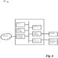
- FIG. 6 is a block diagram of a processing system 600 that may be used for implementing the devices and methods disclosed herein.
- Specific devices may utilize all of the components shown, or only a subset of the components, and levels of integration may vary from device to device.
- a device may contain multiple instances of a component, such as multiple processing units, processors, memories, transmitters, receivers, etc.
- the processing system may comprise a processing unit equipped with one or more input/output devices, such as a speaker, microphone, mouse, touchscreen, keypad, keyboard, printer, display, and the like.
- the processing unit may include a central processing unit (CPU), memory, a mass storage device, a video adapter, and an I/O interface connected to a bus.
- CPU central processing unit
- the bus may be one or more of any type of several bus architectures including a memory bus or memory controller, a peripheral bus, video bus, or the like.
- the CPU may comprise any type of electronic data processor.
- the memory may comprise any type of system memory such as static random access memory (SRAM), dynamic random access memory (DRAM), synchronous DRAM (SDRAM), read-only memory (ROM), a combination thereof, or the like.
- SRAM static random access memory
- DRAM dynamic random access memory
- SDRAM synchronous DRAM
- ROM read-only memory
- the memory may include ROM for use at boot-up, and DRAM for program and data storage for use while executing programs.
- the mass storage device may comprise any type of storage device configured to store data, programs, and other information and to make the data, programs, and other information accessible via the bus.
- the mass storage device may comprise, for example, one or more of a solid state drive, hard disk drive, a magnetic disk drive, an optical disk drive, or the like.
- the video adapter and the I/O interface provide interfaces to couple external input and output devices to the processing unit.
- input and output devices include the display coupled to the video adapter and the mouse/keyboard/printer coupled to the I/O interface.
- Other devices may be coupled to the processing unit, and additional or fewer interface cards may be utilized.
- a serial interface such as Universal Serial Bus (USB) (not shown) may be used to provide an interface for a printer.
- USB Universal Serial Bus
- the processing unit also includes one or more network interfaces, which may comprise wired links, such as an Ethernet cable or the like, and/or wireless links to access nodes or different networks.
- the network interface allows the processing unit to communicate with remote units via the networks.
- the network interface may provide wireless communication via one or more transmitters/transmit antennas and one or more receivers/receive antennas.
- the processing unit is coupled to a local-area network or a wide-area network for data processing and communications with remote devices, such as other processing units, the Internet, remote storage facilities, or the like.
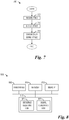
- Figure 7 illustrates a flow diagram of example operations 700 occurring in a D2D communications device synchronizes using a D2DSS.
- Operations 700 may be indicative of operations occurring in a D2D communications device as the device synchronizes using a D2DSS.
- Operations 700 may begin with the D2D communications device receiving a plurality of PRBs (block 705). Included in the plurality of PRBs may be a PD2DSS. The PD2DSS may be generated using techniques such as those described herein. The P2DSS may be transmitted in a SC-FDM waveform. The plurality of PRBs may also include a SD2DSS. The SD2DSS may be generated using techniques such as those described herein. The D2D communications device may detect the PD2DSS (710). The D2D communications device may also detect the SD2DSS. The D2D communications device may synchronize using the PD2DSS (and potentially the SD2DSS) (block 715).
- FIG 8 illustrates an example communications device 800.
- Communications device 800 may be an implementation of a device operating as a D2D synchronization source, such as a D2D UE.
- Communications device 800 may be used to implement various ones of the embodiments discussed herein.
- a transmitter 805 is configured to transmit packets, D2DSS, PD2DSS, SD2DSS, and the like.
- Communications device 800 also includes a receiver 810 that is configured to receive packets, and the like.
- a sequence selecting unit 820 is configured to select a sequence used to derive a D2DSS. Sequence selecting unit 820 is configured to select a ZC sequence. Sequence selecting unit 820 is configured to select a ZC sequence with a length that is different from a length of another ZC sequence used to generate LTE PSS, as well as the length of sequences used to generate other signals transmitted in the uplink of communications device 800, such as DMRS, SRS, and the like.
- Sequence selecting unit 820 is configured to select a root index of a ZC sequence that is different from a root index of another ZC sequence used to generate LTE PSS, as well as the root index of sequences used to generate other signals transmitted in the uplink of communications device 800, such as DMRS, SRS, and the like.
- a signal generating unit 822 is configured to generate a D2DSS, a PD2DSS, a SD2DSS, and the like, in accordance with the sequence selected by sequence selecting unit 820.
- a memory 830 is configured to store sequences, ZC sequences, lengths, root indices, signals, and the like.
- the elements of communications device 800 may be implemented as specific hardware logic blocks. In an alternative, the elements of communications device 800 may be implemented as software executing in a processor, controller, application specific integrated circuit, or so on. In yet another alternative, the elements of communications device 800 may be implemented as a combination of software and/or hardware.
- receiver 810 and transmitter 805 may be implemented as a specific hardware block, while sequence selecting unit 820 and signal generating unit 822 may be software modules executing in a microprocessor (such as processor 815) or a custom circuit or a custom compiled logic array of a field programmable logic array. Sequence selecting unit 820 and signal generating unit 822 may be modules stored in memory 830.
Landscapes
- Engineering & Computer Science (AREA)
- Computer Networks & Wireless Communication (AREA)
- Signal Processing (AREA)
- Databases & Information Systems (AREA)
- Mobile Radio Communication Systems (AREA)
- Digital Transmission Methods That Use Modulated Carrier Waves (AREA)
Description
- The present invention relates to wireless communications, and, in particular embodiments, to a system and method for transmitting a synchronization signal.
- Device-to-Device (D2D) technology is receiving a lot of attention because of the ability to offer new services, improve system throughput, and offer a better user experience. A variety of potential use cases for D2D have been identified.
In order to ensure successful D2D communications, synchronization is crucial: D2D transmitting and receiving user equipments (UEs) should acquire the same time and/or frequency synchronization from synchronization source(s). These sources need to periodically transmit at least a D2D synchronization signal (D2DSS) to ensure D2D UEs derive time and/or frequency synchronization. The synchronization source could be a base station, an evolved NodeB (eNodeB) (like a traditional Third Generation Partnership Project (3GPP) Long Term Evolution (LTE) network), or a D2D UE which is relaying the downlink (DL) synchronization channel from an eNodeB.
"3GPP DRAFT; WF ON THE D2D SYNCHRONIZATION PROCEDURE V8" refers to methods of in coverage synchronization and out of coverage synchronization. In particular, in scenario in coverage, some in-coverage UEs transmit D2DSS based on their synchronization to an eNodeB. UEs can synchronize to the D2DSS transmitted by UEs in another cell for neighbor-cell discovery and communication. - Example embodiments of the present disclosure provide a system and method for transmitting a synchronization signal which aim at ensuring a fine time and frequency synchronization of the D2D UE. Claim 1 and Claim 10 state a solution to this object. Further advantageous embodiments and improvements of the invention are listed in the dependent claims. Hereinafter, some examples and aspects of the invention are highlighted before coming to a detailed discussion of the embodiments of the invention.
- In accordance with an example embodiment of the present disclosure, a method for device-to-device communications is provided. The method includes generating, by a synchronization source, a primary device-to-device synchronization signal that is different from a primary synchronization signal (PSS) sent by an Evolved NodeB (eNodeB) and is different from an existing uplink (UL) signal sent by device-to-device communications devices, and transmitting, by the synchronization source, the primary device-to-device synchronization signal in a single carrier frequency division multiple access (SC-FDMA) waveform, wherein generating the primary device-to-device synchronization signal comprises: generating a synchronization sequence in accordance with a first sequence, wherein a first root index of the first sequence is different from a second root index of a second sequence used to generate the PSS; and mapping the synchronization sequence onto subcarriers to produce the primary device-to-device synchronization signal.
- In accordance with another example embodiment of the present disclosure, a method of operating a device-to-device communications device is provided. The method includes receiving, by the device-to-device communications device, a plurality of physical resource blocks (PRBs) including a primary device-to-device synchronization signal that is different from a primary synchronization signal (PSS) sent by an Evolved NodeB (eNodeB) and is different from an existing uplink (UL) signal sent by device-to-device communications devices, wherein the primary device-to-device synchronization signal is transmitted in a single carrier frequency division multiple access (SC-FDMA) waveform, wherein the primary device-to-device synchronization signal is generated from a synchronization sequence in accordance with a first sequence, wherein a first root index of the first sequence is different from a second root index of a second sequence used to generate the PSS. The method also includes detecting, by the device-to-device communications device, the primary device-to-device synchronization signal in the plurality of PRBs, and synchronizing, by the device-to-device communications device, in accordance with the primary device-to-device synchronization signal.
- In accordance with another example embodiment of the present disclosure, a synchronization source is provided. The synchronization source includes a processor, and a transmitter operatively coupled to the processor. The processor generates a primary device-to-device synchronization signal that is different from a primary synchronization signal (PSS) sent by an Evolved NodeB (eNodeB) and an existing uplink (UL) signal sent by device-to-device communications devices. The transmitter transmits the primary device-to-device synchronization signal in a single carrier frequency division multiple access (SC-FDMA) waveform.
- In accordance with another example embodiment of the present disclosure, a method for device-to-device communications is provided. The method includes generating, by a synchronization source, a primary device-to-device synchronization signal in accordance with

- One advantage of an embodiment is that the use of centrally symmetric signals simplifies decoding complexity.
- For a more complete understanding of the present disclosure, and the advantages thereof, reference is now made to the following descriptions taken in conjunction with the accompanying drawing, in which:
-
Figure 1 illustrates an example communications system according to example embodiments described herein; -
Figure 2 illustrates example subframes according to example embodiments described herein; -
Figure 3 illustrates a flow diagram of example operations occurring in a D2D UE according to example embodiments described herein; -
Figure 4 illustrates a flow diagram of example operations occurring in a D2D UE as the D2D UE generates a D2DSS according to example embodiments described herein; -
Figure 5 illustrates a flow diagram of example operations occurring in a D2D UE as the D2D UE generates a D2DSS in accordance with a ZC sequence with a different root index according to example embodiments described herein; -
Figure 6 illustrates an example computing platform that may be used for implementing, for example, the devices and methods described herein, according to example embodiments described herein; -
Figure 7 illustrates a flow diagram of example operations occurring in a D2D communications device synchronizes using a D2DSS according to example embodiments described herein; and -
Figure 8 illustrates an example communications device according to example embodiments described herein. - The operating of the current example embodiments and the structure thereof are discussed in detail below. It should be appreciated, however, that the present disclosure provides many applicable inventive concepts that can be embodied in a wide variety of specific contexts. The specific embodiments discussed are merely illustrative of specific structures of the disclosure and ways to operate the disclosure, and do not limit the scope of the disclosure.
- The present disclosure will be described with respect to example embodiments in a specific context, namely communications systems that use a synchronization signal to facilitate D2D communications. The disclosure may be applied to standards compliant communications systems, such as those that are compliant with Third Generation Partnership Project (3GPP), IEEE 802.11, and the like, technical standards, and non-standards compliant communications systems, that use a synchronization signal to facilitate D2D communications.
-
Figure 1 illustrates anexample communications system 100.Communications system 100 supports D2D communications and may therefore be referred to as a D2D system. D2D synchronization in a D2D system is highlighted inFigure 1 . As illustrated inFigure 1 , D2DUE1 105, D2DUE2 110, and D2DUE3 115 may derive time and/or frequency synchronization based on legacy LTE DL synchronization channel, such as primary synchronization signal (PSS) and secondary synchronization signal (SSS), sent byeNodeB 120, or other synchronization signals sent by eNodeB 120. At the same time, D2DUE3 115 and D2DUE5 125 also play the role of synchronization sources (i.e., D2D synchronization sources) forD2DUE4 130 and D2DUE6 135, respectively. eNodeBs may also be commonly referred to as NodeBs, controllers, base stations, access points, base terminal stations, and the like. Similarly, UEs may also be commonly referred to as mobile stations, mobiles, terminals, users, stations, subscribers, and the like. While it is understood that communications systems may employ multiple eNodeBs capable of communicating with a number of UEs, only one eNodeB, and a number of UEs are illustrated for simplicity. - Discovery is a D2D technique that includes the ability to discover neighboring UEs. Discovery can be either eNodeB-assisted discovery or open discovery. With eNodeB-assisted discovery, a first UE is directed to transmit a signal (e.g., a sounding reference signal (SRS)), and a second UE is required to listen and report the signal quality to the eNodeB. The eNodeB may, based on this reported signal quality, decide if ProSe can be enabled for these two UEs. With open discovery, any UE may transmit a signal, such as a beacon signal, to advertise its presence to other UEs. It is noted that this process can possibly involve idle UEs.
- Given that open discovery may involve idle UEs, it is typically performed with very limited available information. In particular, the UEs typically have to rely on the information broadcasted by the eNodeB. It may be too costly in most situations to wake up these UEs and transmit radio resource control (RRC) signaling to them. Furthermore, the location of idle UEs is approximate, and the exact cell where the UEs are camping is not known by the communications system.
- For D2D communication, it is also generally assumed that D2D occurs on the uplink (UL) portion of the bandwidth since the interference would be less prejudicial to cellular UEs on the UL. On the UL, a transmitting D2D UE interferes with the eNodeB. Consequently, as long as the D2D UE is at a reasonable distance from the eNodeB, the interference created by the D2D UE has little impact. Conversely, on the DL, D2D interference affects neighboring UEs, and potentially their ability to receive synchronization channels and PDCCH is affected, and can result in significantly higher impact than if the D2D UE were transmitting on the UL.
- Given that D2D communication takes place on the UL, it is reasonable to assume that the D2D discovery occurs on the UL as well. For open discovery, a given number of subframes (e.g., 1%) are reserved for discovery. During these subframes, there usually is no cellular communication at all. Only UE discovery signals are transmitted.
Figure 2 illustratesexample subframes 200. Some of thesubframes 200 are used as discovery subframes (shown as cross-hatched boxes), while others are used as cellular subframes (shown as unshaded boxes). - According to an example embodiment, example D2D synchronization signals are provided. The design principles of D2DSS may include one or more of the following:
- good self-correlation and cross-correlation characteristics, such as with traditional PSS (e.g., based on ZC sequences);
- different from traditional PSS to avoid causing ambiguity to the D2D UEs and just-tuming-on cellular UEs;
- good cross-correlation characteristics regarding the overlap with uplink signals, such as uplink demodulation reference signal (DMRS), since the D2D signal would be transmitted in UL spectrum/subframe;
- possible indication of D2D operating parameters, thereby permitting D2D UEs to quickly obtain D2D configuration information; and
- possible support of fine time and/or frequency synchronization based on the D2DSS, while in an LTE system PSS and/or SSS could only support coarse time and/or frequency synchronization.
- In addition, backwards compatibility can be ensured since a legacy UE should not be able to detect the D2DSS, which would prevent the legacy UE from mistakenly assuming that a D2D UE (source of the D2DSS) is an eNodeB. It is noted that the example embodiments described herein can be combined.
- Moreover, the detection of a D2DSS typically encompasses some form of matched filtering in the receiver, e.g., determining a correlation between the received signal and the D2DSS. Since this involves performing large amounts of complex-valued multiplications, it is an objective to design the D2DSS such that it exhibits signal properties which may be used for reducing the detection complexity.
-
Figure 3 illustrates a flow diagram ofexample operations 300 occurring in a D2D UE.Operations 300 may be indicative of operations occurring in a D2D UE. -
Operations 300 may begin with the D2D UE generating a D2DSS (block 305). The D2D UE may generate a sequence for the D2DSS (e.g., a PD2DSS and/or a SD2DSS). Details of example embodiments of D2DSS are presented below. The D2D UE may map the sequence of the D2DSS, producing a mapped D2DSS (block 310). The D2D UE may map the sequence of the D2DSS to subcarriers so that the D2DSS is centrally symmetric, for example. The D2D UE may transmit the mapped D2DSS (block 315). As discussed previously, the mapped D2DSS may be transmitted in UL resources or subframes. - According to an example embodiment, a D2DSS is based on a ZC sequence with a length that differs from the length of other ZC sequences used in the communications system. A synchronization source transmits a D2DSS based on which a group of D2D UEs (making up a D2D group) derives the time and/or frequency synchronization. The D2DSS may include at least a primary D2DSS (PD2DSS), where the PD2DSS is generated from a first ZC sequence, where the length of the first ZC sequence is different from the length of a second ZC sequence used to generate a legacy LTE PSS sent by eNodeB (the ZC sequence used to generate the legacy LTE PSS is a length 63 sequence, whose central element is punctured in order to produce a length 62 sequence), as well as any possible ZC sequence used to generate existing UL reference signals (including DMRS and SRS) sent by UEs.
- In a first example, a synchronization source, either an eNodeB or D2D UE, transmits a D2DSS based on which group of D2D UEs (making up a D2D group) derives the time/frequency synchronization. The D2DSS should include at least a primary D2DSS (PD2DSS), where the PD2DSS is generated from a first ZC sequence, and where the length of the first ZC sequence is different from the length of a second ZC sequence used to generate the legacy LTE PSS. The use of different length ZC sequences ensures that there will not be a false detection of a D2D UE as an eNodeB. In other words, the PD2DSS will not be mistaken as a PSS. In addition, the ZC sequence length is different from any possible length of ZC sequence used to generate existing UL reference signals (including DMRS and SRS) sent by UEs.
- Furthermore, the length of the first ZC sequence should be a prime number or a number whose second smallest positive submultiple is larger than 3.
-
Figure 4 illustrates a flow diagram ofexample operations 400 occurring in a D2D UE as the D2D UE generates a D2DSS.Operations 400 may be indicative of operations occurring in a D2D UE as the D2D UE generates a D2DSS. -
Operations 400 may begin with the D2D UE selecting a first ZC sequence with a length that is different from the length of a second ZC sequence used to generate a legacy LTE PSS (block 405). Furthermore, the length of the first ZC sequence is also different from the length of other ZC sequences used to generate existing signals transmitted by the D2D UE, such as UL reference signals (including DMRS and SRS). Additionally, the length of the first ZC sequence may be a prime number or a number whose second smallest positive submultiple is larger than 2. The D2D UE may generate the D2DSS using the first ZC sequence (block 410). -
Operations 400, as described herein, focus on the D2D UE generating the D2DSS. However, it may be possible for a different entity in the communications system to generate the D2DSS for the D2D UE and provide the D2DSS to the D2D UE.Operations 400 may be performed any entity in the communications system. Therefore, the discussion of the D2DUE performing operations 400 should not be construed as being limiting to either the scope or the spirit of the example embodiments. - Based on the discussion, the length of the ZC sequence used for the D2DSS (e.g., PD2DSS) may be derived, assuming that the synchronization source transmits PD2DSS within 6 physical resource blocks (PRBs) (72 subcarriers, as is the legacy LTE PSS) in frequency domain. The length of the ZC sequence may be determined based on following principles:
- a prime number or a number whose second smallest positive submultiple is larger than 3;
- not be 63 (the length of the ZC sequence used for the legacy LTE PSS); and
- not be 71, 31 or 47, where 71, 31, 47 are possible lengths ZC sequences used for UL DMRS.
- If all the principles are complied with, the length of the first ZC sequence may be 61, 65, or 67. It is noted that 67 is the maximum value which is not larger than 72 and satisfies above principles, while 61 is the maximum value which is not larger than 64 and satisfies above principles, and 65 is a value whose second smallest positive submultiple is 5 and satisfies above principles. In a typical receiver, the sampling rate may only take certain values, e.g., being a power of 2. As an illustrative example, if the sequence length is up to 64, a receiver window of 64 samples may be utilized, and, similarly, if the sequence length is larger than 64 but less than 128, a receiver window of 128 samples may be utilized. The receiver window length is related to the amount of complex- valued multiplications needed to detect the PD2DSS. Comparing 61 and 67 as possible length values, if the length of the first ZC sequence is 61, only 64 complex samples are needed per PD2DSS, which results in lower complexity. If the length of the first ZC sequence is 67, 128 complex samples are needed per PD2DSS, which result in higher complexity. On the other hand, lower cross correlation could be achieved if the length of the first ZC sequence is 67. Thus, this length should be considered as well if it significantly improves performance.
- A ZC sequence with odd length (e.g., N=61) may be defined as

- The candidate root indices for PD2DSS should be selected to achieve as low cross correlation with legacy PSS as possible. That is, the candidate indices should be selected within {4, 7, 9, 11, 13, 15, 16, 17, 18, 19, 23, 29, 32, 38, 42, 43, 44, 45, 46, 48, 50, 52, 54, 57}.
- The synchronization source may comprise at least a D2DSS, where the D2DSS also should comprise a secondary D2DSS (SD2DSS), where the SD2DSS is generated by a first m-sequence, where the length of the SD2DSS should be different from the length legacy SSS sent by an eNodeB and/or different from the length of the first ZC sequence. This ensures better synchronization, and enables the transmitting node to transmit additional information, such as a frame index or equivalent if it is out-of-coverage. In addition, the sequence length and the bandwidth of SD2DSS should be equal to or larger than that for the PD2DSS.
- The root index of the first ZC sequence may be decided, according to at least one of the following:
- bandwidth of SD2DSS; and
- the root index of the first ZC sequence and/or the first m-sequence is decided according to at least one of the following aspects,
- D2D operating bandwidth;
- identity of the synchronization source, e.g., UE-ID if source is a D2D UE;
- type of the synchronization source, including eNodeB or D2D UE;
- priority of the synchronization source;
- identity of the D2DUE group;
- type of the D2DUE group; and
- priority of the D2DUE group.
- The root index of ZC sequence for a PD2DSS (among all candidates mentioned above) may also convey the information related to the location and/or bandwidth of the corresponding SD2DSS, as well as the D2D operating bandwidth of this D2D group, where the candidate bandwidths include 1.4MHz, 3MHz, 5MHz, 10MHz, 15MHz or 20MHz (6RB, 15RB, 25RB, 50RB, 75RB, or 100RB, where RB is resource block defined in LTE system). An example of the use of such an indication is illustrated in Table 1 below.
Table 1 : Root index for the PD2DSS and corresponding bandwidth of SD2DSS Bandwidth Root index 6RB 19 15RB 23 25RB 29 50RB 32 75RB 38 100RB 42 - In this situation, the length and bandwidth of the SD2DSS may be different from those of the PD2DSS, respectively. It is noted that the larger bandwidth of SD2DSS (than that of the PD2DSS) may help the D2D UEs within the D2D group to achieve fine time and/or frequency synchronization, which is different from the design target of PSS and/or SSS in the LTE communications system.
- According to an example embodiment, a D2DSS is based on a ZC sequence with a different root index for the ZC sequence. In general, two sequences generated from a single sequence but with different root indices will be different sequences. Another solution may be derived assuming that the synchronization source transmits PD2DSS within 6 PRBs (72 subcarriers, like the legacy LTE PSS) in the frequency domain. The first ZC sequence for the PD2DSS may be decided based on following principles:
- a prime number or a number whose second smallest positive submultiple is larger than 3;
- the length should be 71, where 71 is a possible length of the UL DMRS for 6 PRBs transmission;
- root indices should be different from root indices used by the UL DMRS for 6 PRBs transmission;
- if all the principles are complied with, the length of the first ZC sequence may be 71. The candidate root indices of the first ZC sequence should be selected from within set {0, 1, 8, 15, 24, 31, 40, 47, 56, 63}.
-
Figure 5 illustrates a flow diagram ofexample operations 500 occurring in a D2D UE as the D2D UE generates a D2DSS in accordance with a ZC sequence with a different root index.Operations 500 may be indicative of operations occurring in a D2D UE as the D2D UE generates a D2DSS in accordance with a ZC sequence with a different root index. -
Operations 500 may begin with the D2D UE selecting a first ZC sequence with a root index that is different from the root index of a second ZC sequence used to generate a legacy LTE PSS (block 505). Furthermore, the root index of the first ZC sequence is also different from the root index of other ZC sequences used to generate existing signals transmitted by the D2D UE, such as UL reference signals (including DMRS and SRS). Additionally, the length of the first ZC sequence may be the length of the sequence used to generate the UL DMRS. The D2D UE may generate the D2DSS using the first ZC sequence (block 510). -
Operations 500, as described herein, focus on the D2D UE generating the D2DSS. However, it may be possible for a different entity in the communications system to generate the D2DSS for the D2D UE and provide the D2DSS to the D2D UE.Operations 500 may be performed any entity in the communications system. Therefore, the discussion of the D2DUE performing operations 500 should not be construed as being limiting to either the scope or the spirit of the example embodiments. - Furthermore, the D2DSS may also comprise a secondary D2DSS (SD2DSS), where the SD2DSS is generated by an m-sequence, with the length and occupied bandwidth of the SD2DSS being different from that of the legacy SSS sent by an eNodeB.
- The root index of ZC sequence for a PD2DSS (among all candidates mentioned above) may also convey the information of the location and/or bandwidth of the corresponding SD2DSS, as well as the D2D operating bandwidth by this D2D group, where the candidate bandwidths include 1.4MHz, 3MHz, 5MHz, 10MHz, 15MHz or 20MHz (6RB, 15RB, 25RB, 50RB, 75RB, 100RB, where RB is a resource block defined in LTE system). An example of the use of such an indication is illustrated in Table 2 below.
Table 2: Root index for the PD2DSS and corresponding bandwidth of SD2DSS Bandwidth Root index 6RB 15 15RB 24 25RB 31 50RB 40 75RB 47 100RB 56 - In this situation, the length and bandwidth of the SD2DSS may be different from those of the PD2DSS, respectively. It is noted that the larger bandwidth of SD2DSS (than that of the PD2DSS) may help the D2D UEs within the D2D group to achieve fine time and/or frequency synchronization, which is different from the design target of the PSS and/or SSS in the LTE communications system.
- With respect to PD2DSS signal mapping, the PD2DSS may be obtained as a transformation of a set of frequency domain (Fourier) coefficients. As a non-limiting example, suppose that a discrete time-domain base band signal is obtained as:


- If the sequence xu (l), 0 ≤ l ≤ L - 1 where L ≤ N, is mapped to the set of Fourier frequency coefficients such that Hu [l] = Hu [N - l], l = 1,...,N - 1, it may be shown that the signal becomes centrally symmetric, e.g., |su [k]| = |su [N - k]|, k = 1,..., N -1. That is, the Fourier coefficients should be mapped to be symmetric around the DC subcarrier. The PSS is obtained from a symmetric sequence, i.e., a punctured length-63 ZC sequence, which results in a central symmetry according to su [k] = su [N - k], k = 1,...,N - 1. The centrally symmetric property is advantageous as it may be utilized in the receiver to reduce the amount of complex-valued multiplications when performing a correlation of the received signal and the PD2DSS. For example, when determining a correlation value, symmetric samples may be added in the receiver prior to performing multiplication with the replica sample of the D2DSS, thereby reducing the amount of complex-valued multiplications by approximately 50%. Moreover, it may be shown that if there are two sequences which constitute a complex-conjugated pair, i.e.,


- As an illustrative example, a corresponding continuous base band OFDM signal (excluding the cyclic prefix) is generated by (utilizing the periodicity of the discrete Fourier transform


- According to an example embodiment, the PD2DSS is mapped to the Fourier coefficient such that Hu [l] = Hu [N - l], l = 1,...,N - 1 in order to obtain a centrally symmetric signal.
- In another illustrative example, a corresponding continuous base band OFDM signal (excluding the cyclic prefix) is generated by (utilizing the periodicity of the discrete Fourier transform


According to an example embodiment, a synchronization signal for this signal waveform when δ ≠ 0 is designed. This form of signal generation has been used in the UL of the LTE communications system with δ = 1/2 where the DC subcarrier can be modulated, and where it is being referred to as an SC-FDMA signal waveform. The offset δ may be introduced to minimize the impact of distortion in the receiver due to the modulation of the DC subcarrier. It is noted that a centrally symmetric signal, su [k] = -su [N - k], k = 1,..., N - 1, is obtained, e.g., when δ = 1/2 and the Fourier coefficients are symmetric around the DC subcarrier (k = 0). This could be obtained by using a symmetric sequence where L is an even integer. The above waveform may be sampled at instances t = n - Ts to obtain the central symmetry for sequences which are symmetrically mapped to Fourier coefficients around the DC subcarrier. The central symmetry differs from that of the PSS in the negative sign. However, this form of central symmetry still retains the reduction in receiver complexity. It is also realized that the mapping of the synchronization sequence differs from that of the PSS, since a set of contiguous subcarriers may be modulated, whereas for the PSS, the DC subcarrier is left un-modulated. An advantage of the example embodiment is that receiver complexity in the UE for the PD2DSS may be reduced, while at the same time using the existing transmitter and receiver mechanisms based on the single carrier frequency division multiple access (SC-FDMA) signal. - According to an example embodiment, a time-domain symmetric PD2DSS SC-FDMA signal is generated.
- In an example embodiment, a sequence d(n), 0 ≤ n < L - 1 where L is an even integer value and d(n) = d(L - 1 - n), is mapped contiguously to a set of Fourier coefficients, Hu [l],l = 0,1,...,N - 1, such that the Fourier spectrum of su (t) becomes symmetric at the frequencies (k + δ)Δf for a set of integer values k (e.g.,


- In an example embodiment, the sequence d(n) is used for PD2DSS and is generated from a frequency-domain Zadoff-Chu sequence according to expression:


- According to an example embodiment, a discovery sequence is used at the same location of the PSS, but with a different length and/or root index in order to avoid legacy UEs synchronizing with a UE instead of an eNodeB. An example embodiment provides a location mapping for the PSS. An example embodiment works with existing LTE synchronization design to simplify design hardware, standardization efforts, and the like. An example embodiment also allows legacy UEs to still operate on a network where D2D UEs are used.
-
Figure 6 is a block diagram of aprocessing system 600 that may be used for implementing the devices and methods disclosed herein. Specific devices may utilize all of the components shown, or only a subset of the components, and levels of integration may vary from device to device. Furthermore, a device may contain multiple instances of a component, such as multiple processing units, processors, memories, transmitters, receivers, etc. The processing system may comprise a processing unit equipped with one or more input/output devices, such as a speaker, microphone, mouse, touchscreen, keypad, keyboard, printer, display, and the like. The processing unit may include a central processing unit (CPU), memory, a mass storage device, a video adapter, and an I/O interface connected to a bus. - The bus may be one or more of any type of several bus architectures including a memory bus or memory controller, a peripheral bus, video bus, or the like. The CPU may comprise any type of electronic data processor. The memory may comprise any type of system memory such as static random access memory (SRAM), dynamic random access memory (DRAM), synchronous DRAM (SDRAM), read-only memory (ROM), a combination thereof, or the like. In an embodiment, the memory may include ROM for use at boot-up, and DRAM for program and data storage for use while executing programs.
- The mass storage device may comprise any type of storage device configured to store data, programs, and other information and to make the data, programs, and other information accessible via the bus. The mass storage device may comprise, for example, one or more of a solid state drive, hard disk drive, a magnetic disk drive, an optical disk drive, or the like.
- The video adapter and the I/O interface provide interfaces to couple external input and output devices to the processing unit. As illustrated, examples of input and output devices include the display coupled to the video adapter and the mouse/keyboard/printer coupled to the I/O interface. Other devices may be coupled to the processing unit, and additional or fewer interface cards may be utilized. For example, a serial interface such as Universal Serial Bus (USB) (not shown) may be used to provide an interface for a printer.
- The processing unit also includes one or more network interfaces, which may comprise wired links, such as an Ethernet cable or the like, and/or wireless links to access nodes or different networks. The network interface allows the processing unit to communicate with remote units via the networks. For example, the network interface may provide wireless communication via one or more transmitters/transmit antennas and one or more receivers/receive antennas. In an embodiment, the processing unit is coupled to a local-area network or a wide-area network for data processing and communications with remote devices, such as other processing units, the Internet, remote storage facilities, or the like.
-
Figure 7 illustrates a flow diagram ofexample operations 700 occurring in a D2D communications device synchronizes using a D2DSS.Operations 700 may be indicative of operations occurring in a D2D communications device as the device synchronizes using a D2DSS. -
Operations 700 may begin with the D2D communications device receiving a plurality of PRBs (block 705). Included in the plurality of PRBs may be a PD2DSS. The PD2DSS may be generated using techniques such as those described herein. The P2DSS may be transmitted in a SC-FDM waveform. The plurality of PRBs may also include a SD2DSS. The SD2DSS may be generated using techniques such as those described herein. The D2D communications device may detect the PD2DSS (710). The D2D communications device may also detect the SD2DSS. The D2D communications device may synchronize using the PD2DSS (and potentially the SD2DSS) (block 715). -
Figure 8 illustrates anexample communications device 800.Communications device 800 may be an implementation of a device operating as a D2D synchronization source, such as a D2D UE.Communications device 800 may be used to implement various ones of the embodiments discussed herein. As shown inFigure 8 , atransmitter 805 is configured to transmit packets, D2DSS, PD2DSS, SD2DSS, and the like.Communications device 800 also includes areceiver 810 that is configured to receive packets, and the like. - A
sequence selecting unit 820 is configured to select a sequence used to derive a D2DSS.Sequence selecting unit 820 is configured to select a ZC sequence.Sequence selecting unit 820 is configured to select a ZC sequence with a length that is different from a length of another ZC sequence used to generate LTE PSS, as well as the length of sequences used to generate other signals transmitted in the uplink ofcommunications device 800, such as DMRS, SRS, and the like.Sequence selecting unit 820 is configured to select a root index of a ZC sequence that is different from a root index of another ZC sequence used to generate LTE PSS, as well as the root index of sequences used to generate other signals transmitted in the uplink ofcommunications device 800, such as DMRS, SRS, and the like. Asignal generating unit 822 is configured to generate a D2DSS, a PD2DSS, a SD2DSS, and the like, in accordance with the sequence selected bysequence selecting unit 820. Amemory 830 is configured to store sequences, ZC sequences, lengths, root indices, signals, and the like. - The elements of
communications device 800 may be implemented as specific hardware logic blocks. In an alternative, the elements ofcommunications device 800 may be implemented as software executing in a processor, controller, application specific integrated circuit, or so on. In yet another alternative, the elements ofcommunications device 800 may be implemented as a combination of software and/or hardware. - As an example,
receiver 810 andtransmitter 805 may be implemented as a specific hardware block, whilesequence selecting unit 820 andsignal generating unit 822 may be software modules executing in a microprocessor (such as processor 815) or a custom circuit or a custom compiled logic array of a field programmable logic array.Sequence selecting unit 820 andsignal generating unit 822 may be modules stored inmemory 830. - Although the present disclosure and its advantages have been described in detail, it should be understood that various changes, substitutions and alterations can be made herein without departing from the disclosure as defined by the appended claims.
Claims (16)
- A method for device-to-device communications, the method comprises:generating (305), by a synchronization source, a primary device-to-device synchronization signal that is different from a primary synchronization signal, PSS, sent by an Evolved NodeB, eNodeB, and is different from an existing uplink ,UL, signal sent by device-to-device communications devices; andtransmitting (315), by the synchronization source, the primary device-to-device synchronization signal in a single carrier frequency division multiple access, SC-FDMA, waveform;wherein generating the primary device-to-device synchronization signal comprises:generating a synchronization sequence in accordance with a first sequence, wherein a first root index of the first sequence is different from a second root index of a second sequence used to generate the PSS; andmapping the synchronization sequence onto subcarriers to produce the primary device-to-device synchronization signal.
- The method of claim 1, wherein the first sequence comprises a first punctured Zadoff-Chu ,ZC, sequence, and wherein the second sequence comprises a second punctured ZC sequence.
- The method of claim1 or 2, wherein mapping the primary device-to-device synchronization signal comprises mapping the synchronization sequence to the subcarriers so that the primary device-to-device synchronization signal is centrally symmetric.
- The method of claim 3, wherein for N samples of the primary device-to-device synchronization signal, the central symmetry is according to s[k] = -s[N - k], k = 1,...,N - 1, where N is an integer value.
- The method according to any of claim 1 to 4, wherein the synchronization signal is generated in accordance with

- The method of claim 5, wherein the synchronization sequence is expressible as


- The method according to any of claim 1 to 6, wherein the first root index is selected in accordance with an identifier of the synchronization source.
- The method according to any of claim 1 to 6, wherein the primary device-to-device synchronization signal is transmitted without discrete Fourier transform, DFT, precoding.
- A method of operating a device-to-device communications device, the method comprising:receiving (705), by the device-to-device communications device, a plurality of physical resource blocks, PRBs, including a primary device-to-device synchronization signal that is different from a primary synchronization signal, PSS, sent by an Evolved NodeB, eNodeB, and is different from an existing uplink, UL, signal sent by device-to-device communications devices, wherein the primary device-to-device synchronization signal is transmitted in a single carrier frequency division multiple access, SC-FDMA, waveform, wherein the primary device-to-device synchronization signal is generated by a synchronization sequence in accordance with a first sequence, wherein a first root index of the first sequence is different from a second root index of a second sequence used to generate the PSS;detecting (710), by the device-to-device communications device, the primary device-to-device synchronization signal in the plurality of PRBs; andsynchronizing (715), by the device-to-device communications device, in accordance with the primary device-to-device synchronization signal.
- The method of claim 9, wherein the primary device-to-device synchronization signal is centrally symmetric.
- A synchronization source comprising:a processor(815) configured to generate a primary device-to-device synchronization signal that is different from a primary synchronization signal, PSS, sent by an Evolved NodeB, eNodeB, and is different from an existing uplink, UL, signal sent by device-to-device communications devices; anda transmitter(805) operatively coupled to the processor, the transmitter configured to transmit the primary device-to-device synchronization signal in a single carrier frequency division multiple access, SC-FDMA, waveform;wherein the processor is configured to generate a synchronization sequence in accordance with a first sequence, wherein a first root index of the first sequence is different from a second root index of a second sequence used to generate the PSS, and to map the synchronization sequence onto subcarriers to produce the primary device-to-device synchronization signal.
- The synchronization source of claim 11, wherein the synchronization sequence is expressible as

- The synchronization source of claim 11, wherein the first sequence comprises a first punctured Zadoff-Chu, ZC, sequence, and wherein the second sequence comprises a second punctured ZC sequence.
- The synchronization source according to any of claim 11 to 13, wherein the processor is configured to map the synchronization sequence to the subcarriers so that the primary device-to-device synchronization signal is centrally symmetric.
- A device-to-device communications device comprising:means for receiving (705) a plurality of physical resource blocks, PRBs, including a primary device-to-device synchronization signal that is different from a primary synchronization signal, PSS, sent by an Evolved NodeB, eNodeB, and an existing uplink,UL, signal sent by device-to-device communications devices, wherein the primary device-to-device synchronization signal is transmitted in a single carrier frequency division multiple access, SC-FDMA, waveform; wherein the primary device-to-device synchronization signal is generated by a synchronization sequence in accordance with a first sequence, wherein a first root index of the first sequence is different from a second root index of a second sequence used to generate the PSS;means for detecting (710) the primary device-to-device synchronization signal in the plurality of PRBs; andmeans for synchronizing (715) in accordance with the primary device-to-device synchronization signal.
- The device-to-device communications device of claim 15, wherein the primary device-to-device synchronization signal is centrally symmetric.
Priority Applications (1)
| Application Number | Priority Date | Filing Date | Title |
|---|---|---|---|
| EP18183080.3A EP3404882A1 (en) | 2013-11-01 | 2014-11-03 | System and method for transmitting a synchronization signal |
Applications Claiming Priority (3)
| Application Number | Priority Date | Filing Date | Title |
|---|---|---|---|
| US201361898973P | 2013-11-01 | 2013-11-01 | |
| US14/530,322 US9615341B2 (en) | 2013-11-01 | 2014-10-31 | System and method for transmitting a synchronization signal |
| PCT/US2014/063726 WO2015066632A1 (en) | 2013-11-01 | 2014-11-03 | System and method for transmitting a synchronization signal |
Related Child Applications (2)
| Application Number | Title | Priority Date | Filing Date |
|---|---|---|---|
| EP18183080.3A Division EP3404882A1 (en) | 2013-11-01 | 2014-11-03 | System and method for transmitting a synchronization signal |
| EP18183080.3A Division-Into EP3404882A1 (en) | 2013-11-01 | 2014-11-03 | System and method for transmitting a synchronization signal |
Publications (3)
| Publication Number | Publication Date |
|---|---|
| EP3063880A1 EP3063880A1 (en) | 2016-09-07 |
| EP3063880A4 EP3063880A4 (en) | 2017-02-15 |
| EP3063880B1 true EP3063880B1 (en) | 2018-09-05 |
Family
ID=53005269
Family Applications (2)
| Application Number | Title | Priority Date | Filing Date |
|---|---|---|---|
| EP14857687.9A Active EP3063880B1 (en) | 2013-11-01 | 2014-11-03 | System and method for transmitting a synchronization signal |
| EP18183080.3A Pending EP3404882A1 (en) | 2013-11-01 | 2014-11-03 | System and method for transmitting a synchronization signal |
Family Applications After (1)
| Application Number | Title | Priority Date | Filing Date |
|---|---|---|---|
| EP18183080.3A Pending EP3404882A1 (en) | 2013-11-01 | 2014-11-03 | System and method for transmitting a synchronization signal |
Country Status (8)
| Country | Link |
|---|---|
| US (2) | US9615341B2 (en) |
| EP (2) | EP3063880B1 (en) |
| JP (1) | JP6308600B2 (en) |
| KR (2) | KR101993869B1 (en) |
| CN (3) | CN109714736B (en) |
| BR (1) | BR112016009796B1 (en) |
| RU (1) | RU2629165C1 (en) |
| WO (1) | WO2015066632A1 (en) |
Cited By (1)
| Publication number | Priority date | Publication date | Assignee | Title |
|---|---|---|---|---|
| US20210274443A1 (en) * | 2018-05-11 | 2021-09-02 | Zte Corporation | Signal Sending and Receiving Method and Apparatus |
Families Citing this family (33)
| Publication number | Priority date | Publication date | Assignee | Title |
|---|---|---|---|---|
| US10015828B2 (en) * | 2013-04-10 | 2018-07-03 | Telefonaktiebolaget L M Ericsson (Publ) | Method and wireless device for providing device-to-device communication |
| KR102061650B1 (en) * | 2013-04-30 | 2020-01-03 | 삼성전자주식회사 | A method and apparatus for synchronizaton of device to device communication in unlicensed bands |
| US9276693B2 (en) * | 2013-10-15 | 2016-03-01 | Electronics And Telecommunications Research Institute | Apparatus and method for transmitting synchronization signal |
| US9615341B2 (en) | 2013-11-01 | 2017-04-04 | Futurewei Technologies, Inc. | System and method for transmitting a synchronization signal |
| CN110365366B (en) * | 2013-11-01 | 2021-09-03 | 华为技术有限公司 | Transmitter, receiver and method of generating synchronization signal |
| US9967842B2 (en) * | 2013-11-11 | 2018-05-08 | Lg Electronics Inc. | Method for detecting synchronization signal for device-to-device (D2D) communication in wireless communication system and apparatus therefor |
| EP3099123B1 (en) | 2014-01-26 | 2019-11-13 | LG Electronics Inc. | Method for transmitting synchronization signal and synchronization channel in wireless communication system supporting device-to-device communication and apparatus for same |
| US9609503B2 (en) * | 2014-01-28 | 2017-03-28 | Samsung Electronics Co., Ltd | Method and device for detecting and generating synchronization signal for device-to-device wireless communication |
| US20170006563A1 (en) * | 2014-01-31 | 2017-01-05 | Telefonaktiebolaget Lm Ericsson (Publ) | Monitoring Synchronization Signals in Device-to-Device Communication |
| US10263825B2 (en) * | 2014-02-05 | 2019-04-16 | Lg Electronics Inc. | Method and device for transmitting synchronization signal for D2D (device to device) communication in wireless communication system |
| WO2015122715A1 (en) | 2014-02-13 | 2015-08-20 | 엘지전자 주식회사 | Method for transmitting/receiving synchronization signal for d2d communication in wireless communication system, and apparatus therefor |
| US10862634B2 (en) | 2014-03-07 | 2020-12-08 | Huawei Technologies Co., Ltd. | Systems and methods for OFDM with flexible sub-carrier spacing and symbol duration |
| KR102247142B1 (en) * | 2014-05-09 | 2021-05-04 | 삼성전자주식회사 | Method and apparatus for transmitting synchronization signals in device-to-device communication |
| KR102423501B1 (en) * | 2014-05-09 | 2022-07-21 | 엘지전자 주식회사 | Method for transmitting synchronization signal for direct communication between terminals in wireless communication system, and apparatus therefor |
| CN106664674B (en) * | 2014-10-07 | 2020-03-24 | Lg 电子株式会社 | Method for transmitting synchronization signal for device-to-device communication in wireless communication system and apparatus therefor |
| CN107534946B (en) * | 2015-04-30 | 2020-09-04 | 瑞典爱立信有限公司 | Method for use in a radio node and associated radio node |
| CN106303900B (en) * | 2015-05-15 | 2020-10-30 | 索尼公司 | Wireless communication apparatus and wireless communication method |
| WO2017070944A1 (en) | 2015-10-30 | 2017-05-04 | 华为技术有限公司 | Signal sending device and receiving device, and method and system for symbol timing synchronization |
| JP6816857B2 (en) | 2016-01-20 | 2021-01-20 | ホアウェイ・テクノロジーズ・カンパニー・リミテッド | Synchronous information transmission method and device |
| KR101860205B1 (en) * | 2016-06-29 | 2018-05-23 | 한국과학기술원 | Apparatus and method for communicating through random access |
| EP3520275A1 (en) | 2016-09-30 | 2019-08-07 | Sony Mobile Communications Inc. | Subcarrier spacing selection for synchronization signals |
| US10448364B2 (en) * | 2017-01-19 | 2019-10-15 | Qualcomm Incorporated | Methods and apparatus related to time tracking in multi carrier systems |
| WO2018160036A1 (en) * | 2017-03-02 | 2018-09-07 | 엘지전자 주식회사 | Method and apparatus for transmitting sidelink signal in wireless communication system |
| US11368344B2 (en) * | 2017-03-15 | 2022-06-21 | Motorola Mobility Llc | Method and apparatus having a synchronization signal sequence structure for low complexity cell detection |
| US10680866B2 (en) * | 2017-03-24 | 2020-06-09 | Huawei Technologies Co., Ltd. | Sounding reference signal design |
| WO2018203627A1 (en) * | 2017-05-02 | 2018-11-08 | 엘지전자(주) | Method for transmitting and receiving signals in wireless communication system and device therefor |
| US11051263B2 (en) * | 2017-06-15 | 2021-06-29 | Qualcomm Incorporated | Synchronization channel and system acquisition for internet of things communications in a shared spectrum |
| CN115102662A (en) * | 2017-06-16 | 2022-09-23 | 摩托罗拉移动有限责任公司 | Method and apparatus for establishing a set of multiple synchronization signal sequences for use with one or more communication targets |
| CN109842478A (en) * | 2017-11-26 | 2019-06-04 | 华为技术有限公司 | A kind of sequence determines method and apparatus |
| US10439779B2 (en) | 2017-11-26 | 2019-10-08 | Huawei Technologies Co., Ltd. | Sequence determining method and apparatus |
| CN111052816A (en) | 2018-02-09 | 2020-04-21 | Oppo广东移动通信有限公司 | Method, apparatus and computer storage medium for transmitting synchronization signal |
| US11696241B2 (en) * | 2019-07-30 | 2023-07-04 | Qualcomm Incorporated | Techniques for synchronizing based on sidelink synchronization signal prioritization |
| CN112422218B (en) * | 2019-08-21 | 2022-09-09 | 华为技术有限公司 | Synchronization signal transmission method and communication device |
Family Cites Families (52)
| Publication number | Priority date | Publication date | Assignee | Title |
|---|---|---|---|---|
| US8170081B2 (en) * | 2004-04-02 | 2012-05-01 | Rearden, LLC. | System and method for adjusting DIDO interference cancellation based on signal strength measurements |
| DE602006016492D1 (en) * | 2006-01-18 | 2010-10-07 | Huawei Tech Co Ltd | ORMATION TRANSMISSION IN A COMMUNICATION SYSTEM |
| US9462564B2 (en) | 2006-05-01 | 2016-10-04 | Nokia Technologies Oy | Apparatus, method and computer program product providing uplink synchronization through use of dedicated uplink resource assignment |
| US7756198B2 (en) | 2006-08-18 | 2010-07-13 | Fujitsu Limited | System and method for assigning channels in a wireless network |
| CN101641874B (en) | 2006-08-18 | 2013-11-06 | 富士通株式会社 | New and legacy wireless communication device coexisting amble sequence |
| GB2458418B (en) | 2006-12-19 | 2011-08-03 | Lg Electronics Inc | Sequence generating method for efficient detection and method for transmitting and receiving signals using the same |
| CN101573899B (en) | 2007-01-08 | 2013-01-23 | Lm爱立信电话有限公司 | Secondary synchronization sequences for cell group detection in a cellular communications system |
| DK2090050T4 (en) | 2007-05-02 | 2017-09-25 | Huawei Tech Co Ltd | Method of establishing a synchronization signal in a communication system. |
| US8223908B2 (en) | 2007-05-02 | 2012-07-17 | Qualcomm Incorporated | Selection of acquisition sequences for optimal frequency offset estimation |
| US8014424B2 (en) * | 2007-06-25 | 2011-09-06 | Qualcomm Incorporated | Method and apparatus for using an unique index set for PSC sequence in a wireless communication system |
| CN101502018B (en) * | 2007-08-15 | 2013-06-05 | 华为技术有限公司 | Generation and detection of synchronization signals |
| CN101136696B (en) * | 2007-09-27 | 2012-11-14 | 中兴通讯股份有限公司 | Method to generate single carrier frequency division multiple address signal of uplink sharing channel |
| KR101599844B1 (en) | 2007-12-24 | 2016-03-04 | 엘지전자 주식회사 | Method of Multiplexing Multiple Access Region |
| EP2340681B1 (en) | 2008-09-25 | 2014-11-12 | Nokia Corporation | Synchronization for device-to-device communication |
| EP2202933B1 (en) | 2008-12-23 | 2016-10-26 | Telefonaktiebolaget LM Ericsson (publ) | Technique for generating an sc-fdma signal |
| WO2010110568A2 (en) | 2009-03-22 | 2010-09-30 | 엘지전자 주식회사 | Channel-sounding method using a plurality of antennas, and apparatus for same |
| CN102111758A (en) * | 2009-12-28 | 2011-06-29 | 北京安码科技有限公司 | Method for solving end-to-end problem in mobile communication based on encryption system |
| US8792433B2 (en) | 2010-05-11 | 2014-07-29 | Qualcomm Incorporated | Hardware implementation of uplink receiver with matched throughput |
| US9420570B2 (en) | 2010-07-26 | 2016-08-16 | Lg Electronics Inc. | Method and device for transmitting an uplink control signal in a wireless communication system |
| WO2013002688A1 (en) * | 2011-06-29 | 2013-01-03 | Telefonaktiebolaget L M Ericsson (Publ) | A method and a user equipment for peer-to-peer communication |
| KR101427072B1 (en) | 2011-07-27 | 2014-08-05 | 엘지전자 주식회사 | Method for transmitting an uplink reference signal in a multi-node system and terminal using same |
| US9414337B2 (en) | 2011-08-23 | 2016-08-09 | Lg Electronics Inc. | Method for transmitting and receiving synchronization signals in wireless access system and apparatus therefor |
| CN103108405B (en) * | 2011-11-15 | 2017-09-08 | 中兴通讯股份有限公司 | Wireless communications method and system |
| CN103108389A (en) * | 2011-11-15 | 2013-05-15 | 中兴通讯股份有限公司 | Communication method and communication system from device to device and user devices |
| WO2013077684A1 (en) * | 2011-11-24 | 2013-05-30 | 엘지전자 주식회사 | Method for performing device-to-device communication in wireless access system and apparatus for same |
| US20140342747A1 (en) * | 2012-01-18 | 2014-11-20 | Lg Electronics Inc. | Device-to-device communication method and a device therefor |
| US9521644B2 (en) * | 2012-01-31 | 2016-12-13 | Qualcomm Incorporated | Methods and apparatus for providing network-assisted end-to-end paging between LTE devices |
| US9325555B2 (en) | 2012-02-24 | 2016-04-26 | Lg Electronics Inc. | Method and device for tracking synchronization |
| WO2013125887A1 (en) | 2012-02-24 | 2013-08-29 | 엘지전자 주식회사 | Transmission method and transmission device |
| US9258692B2 (en) * | 2012-03-30 | 2016-02-09 | Qualcomm Incorporated | Relay assisted peer discovery |
| CN103379617B (en) * | 2012-04-26 | 2016-08-10 | 华为技术有限公司 | A kind of subscriber equipment is to the communication means of subscriber equipment and subscriber equipment |
| US9002281B2 (en) | 2012-04-30 | 2015-04-07 | Intel Corporation | Apparatus and method to enable device-to-device (D2D) communication in cellular networks |
| TWI532352B (en) * | 2012-05-04 | 2016-05-01 | 財團法人資訊工業策進會 | Evolved packet core less direct mode communication system and communication attaching method thereof |
| CN102769868B (en) * | 2012-07-23 | 2014-10-29 | 西安电子科技大学 | M2M (Machine to Machine) service wireless resource dispatching method based on TD-SCDMA (Time Division-Synchronous Code Division Multiple Access) network |
| CN102780993B (en) * | 2012-08-20 | 2015-04-15 | 哈尔滨工业大学 | Terminal D2D (device-to-device) cooperation relay communication implementation method in TD-LTE-A (time division-long term evolution-advanced) system |
| US9451570B2 (en) * | 2012-08-29 | 2016-09-20 | Alcatel Lucent | Device discovery for device-to-device communication |
| US8923464B2 (en) * | 2012-11-16 | 2014-12-30 | Qualcomm Incorporated | Methods and apparatus for enabling distributed frequency synchronization |
| US9185697B2 (en) * | 2012-12-27 | 2015-11-10 | Google Technology Holdings LLC | Method and apparatus for device-to-device communication |
| JP2016519478A (en) * | 2013-04-02 | 2016-06-30 | エルジー エレクトロニクス インコーポレイティド | Discovery signal transmission method and apparatus for direct communication between terminals in wireless communication system |
| KR102243662B1 (en) * | 2013-09-01 | 2021-04-23 | 엘지전자 주식회사 | Method for transmitting sync signals for device-to-device (d2d) communication in wireless communication system and apparatus therefor |
| KR102210635B1 (en) * | 2013-09-27 | 2021-02-02 | 엘지전자 주식회사 | Method for synchronization between user equipment for device-to-device (d2d) communication in wireless communication system and apparatus for same |
| CN103595679B (en) * | 2013-10-27 | 2016-05-25 | 西安电子科技大学 | Reduce the method for LTE uplink single-carrier frequency division multiple address signal peak-to-average force ratio |
| KR102238537B1 (en) * | 2013-10-28 | 2021-04-09 | 엘지전자 주식회사 | Method and apparatus for transmitting and receiving signal for device-to-device terminal in wireless communication system |
| EP3063914B1 (en) * | 2013-10-31 | 2019-04-03 | Huawei Technologies Co., Ltd. | System and method for device-to-device synchronization |
| US9615341B2 (en) | 2013-11-01 | 2017-04-04 | Futurewei Technologies, Inc. | System and method for transmitting a synchronization signal |
| CN110365366B (en) * | 2013-11-01 | 2021-09-03 | 华为技术有限公司 | Transmitter, receiver and method of generating synchronization signal |
| US9609503B2 (en) | 2014-01-28 | 2017-03-28 | Samsung Electronics Co., Ltd | Method and device for detecting and generating synchronization signal for device-to-device wireless communication |
| US10263825B2 (en) | 2014-02-05 | 2019-04-16 | Lg Electronics Inc. | Method and device for transmitting synchronization signal for D2D (device to device) communication in wireless communication system |
| US10244493B2 (en) | 2014-08-26 | 2019-03-26 | Lg Electronics Inc. | Method for transmitting and receiving synchronization signal in wireless communication system and device for performing same |
| WO2016034106A1 (en) | 2014-09-04 | 2016-03-10 | Huawei Technologies Co., Ltd. | System and method for communicating resource allocation for d2d |
| KR101901950B1 (en) | 2014-09-05 | 2018-09-28 | 엘지전자 주식회사 | Method for performing communication between devices in wireless communication system and device for performing same |
| US9439039B1 (en) | 2015-08-06 | 2016-09-06 | Qualcomm Incorporated | Device-to-device ranging and positioning |
-
2014
- 2014-10-31 US US14/530,322 patent/US9615341B2/en active Active
- 2014-11-03 EP EP14857687.9A patent/EP3063880B1/en active Active
- 2014-11-03 WO PCT/US2014/063726 patent/WO2015066632A1/en active Application Filing
- 2014-11-03 JP JP2016527423A patent/JP6308600B2/en active Active
- 2014-11-03 RU RU2016121479A patent/RU2629165C1/en active
- 2014-11-03 BR BR112016009796-3A patent/BR112016009796B1/en active IP Right Grant
- 2014-11-03 CN CN201910107386.9A patent/CN109714736B/en active Active
- 2014-11-03 CN CN201480058761.0A patent/CN105684324B/en active Active
- 2014-11-03 EP EP18183080.3A patent/EP3404882A1/en active Pending
- 2014-11-03 CN CN201910107427.4A patent/CN109831269B/en active Active
- 2014-11-03 KR KR1020187019304A patent/KR101993869B1/en active IP Right Grant
- 2014-11-03 KR KR1020167013926A patent/KR20160078418A/en active Application Filing
-
2017
- 2017-01-11 US US15/403,892 patent/US10306573B2/en active Active
Non-Patent Citations (1)
| Title |
|---|
| None * |
Cited By (2)
| Publication number | Priority date | Publication date | Assignee | Title |
|---|---|---|---|---|
| US20210274443A1 (en) * | 2018-05-11 | 2021-09-02 | Zte Corporation | Signal Sending and Receiving Method and Apparatus |
| US11665643B2 (en) * | 2018-05-11 | 2023-05-30 | Zte Corporation | Signal sending and receiving method and apparatus |
Also Published As
| Publication number | Publication date |
|---|---|
| CN105684324A (en) | 2016-06-15 |
| US20170127365A1 (en) | 2017-05-04 |
| RU2629165C1 (en) | 2017-08-24 |
| CN109714736A (en) | 2019-05-03 |
| CN109714736B (en) | 2021-09-07 |
| US9615341B2 (en) | 2017-04-04 |
| KR101993869B1 (en) | 2019-06-27 |
| JP6308600B2 (en) | 2018-04-11 |
| CN109831269A (en) | 2019-05-31 |
| US10306573B2 (en) | 2019-05-28 |
| BR112016009796A2 (en) | 2017-08-01 |
| EP3063880A4 (en) | 2017-02-15 |
| CN105684324B (en) | 2019-03-01 |
| KR20180080373A (en) | 2018-07-11 |
| JP2016538777A (en) | 2016-12-08 |
| EP3404882A1 (en) | 2018-11-21 |
| KR20160078418A (en) | 2016-07-04 |
| WO2015066632A1 (en) | 2015-05-07 |
| EP3063880A1 (en) | 2016-09-07 |
| US20150124579A1 (en) | 2015-05-07 |
| BR112016009796B1 (en) | 2023-04-11 |
| CN109831269B (en) | 2020-06-16 |
Similar Documents
| Publication | Publication Date | Title |
|---|---|---|
| EP3063880B1 (en) | System and method for transmitting a synchronization signal | |
| US11916813B2 (en) | Method and device for indicating sub-band configuration, and method and device for accessing sub-band | |
| US10805863B2 (en) | Method and apparatus for generating and using reference signal for broadcast channel for radio system | |
| US11122530B2 (en) | Method and apparatus of synchronizing device to device terminals in time and frequency | |
| EP3096481A1 (en) | Signal transmission method and apparatus | |
| EP4236160A2 (en) | Broadcast of information for new carrier type | |
| US20160066291A1 (en) | Communication system | |
| JP7206273B2 (en) | Detection window indication method and device | |
| EP4236223A2 (en) | Systems and methods for multi-physical structure system | |
| US10602515B2 (en) | Guard band with synchronization information | |
| US20230007603A1 (en) | Methods for enabling a reduced bandwidth wireless device to access a cell | |
| WO2017133676A1 (en) | Method and device for transmitting and receiving reference signal, and transmission system | |
| WO2014059591A1 (en) | Initial access for standalone carrier type | |
| WO2018024246A1 (en) | Method and device for mapping and detecting channel, base station and user equipment | |
| JP7306568B2 (en) | Communication method |
Legal Events
| Date | Code | Title | Description |
|---|---|---|---|
| PUAI | Public reference made under article 153(3) epc to a published international application that has entered the european phase |
Free format text: ORIGINAL CODE: 0009012 |
|
| 17P | Request for examination filed |
Effective date: 20160504 |
|
| AK | Designated contracting states |
Kind code of ref document: A1 Designated state(s): AL AT BE BG CH CY CZ DE DK EE ES FI FR GB GR HR HU IE IS IT LI LT LU LV MC MK MT NL NO PL PT RO RS SE SI SK SM TR |
|
| AX | Request for extension of the european patent |
Extension state: BA ME |
|
| RIC1 | Information provided on ipc code assigned before grant |
Ipc: H04J 13/00 20110101ALI20161006BHEP Ipc: H04L 27/26 20060101AFI20161006BHEP |
|
| REG | Reference to a national code |
Ref country code: DE Ref legal event code: R079 Ref document number: 602014032041 Country of ref document: DE Free format text: PREVIOUS MAIN CLASS: H04B0007212000 Ipc: H04L0027260000 |
|
| DAX | Request for extension of the european patent (deleted) | ||
| A4 | Supplementary search report drawn up and despatched |
Effective date: 20170116 |
|
| RIC1 | Information provided on ipc code assigned before grant |
Ipc: H04J 13/00 20110101ALI20170110BHEP Ipc: H04L 27/26 20060101AFI20170110BHEP |
|
| GRAP | Despatch of communication of intention to grant a patent |
Free format text: ORIGINAL CODE: EPIDOSNIGR1 |
|
| STAA | Information on the status of an ep patent application or granted ep patent |
Free format text: STATUS: GRANT OF PATENT IS INTENDED |
|
| INTG | Intention to grant announced |
Effective date: 20180319 |
|
| GRAS | Grant fee paid |
Free format text: ORIGINAL CODE: EPIDOSNIGR3 |
|
| GRAA | (expected) grant |
Free format text: ORIGINAL CODE: 0009210 |
|
| STAA | Information on the status of an ep patent application or granted ep patent |
Free format text: STATUS: THE PATENT HAS BEEN GRANTED |
|
| AK | Designated contracting states |
Kind code of ref document: B1 Designated state(s): AL AT BE BG CH CY CZ DE DK EE ES FI FR GB GR HR HU IE IS IT LI LT LU LV MC MK MT NL NO PL PT RO RS SE SI SK SM TR |
|
| REG | Reference to a national code |
Ref country code: GB Ref legal event code: FG4D |
|
| REG | Reference to a national code |
Ref country code: CH Ref legal event code: EP |
|
| REG | Reference to a national code |
Ref country code: AT Ref legal event code: REF Ref document number: 1039202 Country of ref document: AT Kind code of ref document: T Effective date: 20180915 |
|
| REG | Reference to a national code |
Ref country code: IE Ref legal event code: FG4D |
|
| REG | Reference to a national code |
Ref country code: DE Ref legal event code: R096 Ref document number: 602014032041 Country of ref document: DE |
|
| REG | Reference to a national code |
Ref country code: NL Ref legal event code: FP |
|
| REG | Reference to a national code |
Ref country code: LT Ref legal event code: MG4D |
|
| PG25 | Lapsed in a contracting state [announced via postgrant information from national office to epo] |
Ref country code: NO Free format text: LAPSE BECAUSE OF FAILURE TO SUBMIT A TRANSLATION OF THE DESCRIPTION OR TO PAY THE FEE WITHIN THE PRESCRIBED TIME-LIMIT Effective date: 20181205 Ref country code: BG Free format text: LAPSE BECAUSE OF FAILURE TO SUBMIT A TRANSLATION OF THE DESCRIPTION OR TO PAY THE FEE WITHIN THE PRESCRIBED TIME-LIMIT Effective date: 20181205 Ref country code: GR Free format text: LAPSE BECAUSE OF FAILURE TO SUBMIT A TRANSLATION OF THE DESCRIPTION OR TO PAY THE FEE WITHIN THE PRESCRIBED TIME-LIMIT Effective date: 20181206 Ref country code: SE Free format text: LAPSE BECAUSE OF FAILURE TO SUBMIT A TRANSLATION OF THE DESCRIPTION OR TO PAY THE FEE WITHIN THE PRESCRIBED TIME-LIMIT Effective date: 20180905 Ref country code: FI Free format text: LAPSE BECAUSE OF FAILURE TO SUBMIT A TRANSLATION OF THE DESCRIPTION OR TO PAY THE FEE WITHIN THE PRESCRIBED TIME-LIMIT Effective date: 20180905 Ref country code: LT Free format text: LAPSE BECAUSE OF FAILURE TO SUBMIT A TRANSLATION OF THE DESCRIPTION OR TO PAY THE FEE WITHIN THE PRESCRIBED TIME-LIMIT Effective date: 20180905 Ref country code: RS Free format text: LAPSE BECAUSE OF FAILURE TO SUBMIT A TRANSLATION OF THE DESCRIPTION OR TO PAY THE FEE WITHIN THE PRESCRIBED TIME-LIMIT Effective date: 20180905 |
|
| REG | Reference to a national code |
Ref country code: AT Ref legal event code: MK05 Ref document number: 1039202 Country of ref document: AT Kind code of ref document: T Effective date: 20180905 |
|
| PG25 | Lapsed in a contracting state [announced via postgrant information from national office to epo] |
Ref country code: AL Free format text: LAPSE BECAUSE OF FAILURE TO SUBMIT A TRANSLATION OF THE DESCRIPTION OR TO PAY THE FEE WITHIN THE PRESCRIBED TIME-LIMIT Effective date: 20180905 Ref country code: LV Free format text: LAPSE BECAUSE OF FAILURE TO SUBMIT A TRANSLATION OF THE DESCRIPTION OR TO PAY THE FEE WITHIN THE PRESCRIBED TIME-LIMIT Effective date: 20180905 Ref country code: HR Free format text: LAPSE BECAUSE OF FAILURE TO SUBMIT A TRANSLATION OF THE DESCRIPTION OR TO PAY THE FEE WITHIN THE PRESCRIBED TIME-LIMIT Effective date: 20180905 |
|
| PG25 | Lapsed in a contracting state [announced via postgrant information from national office to epo] |
Ref country code: PL Free format text: LAPSE BECAUSE OF FAILURE TO SUBMIT A TRANSLATION OF THE DESCRIPTION OR TO PAY THE FEE WITHIN THE PRESCRIBED TIME-LIMIT Effective date: 20180905 Ref country code: EE Free format text: LAPSE BECAUSE OF FAILURE TO SUBMIT A TRANSLATION OF THE DESCRIPTION OR TO PAY THE FEE WITHIN THE PRESCRIBED TIME-LIMIT Effective date: 20180905 Ref country code: IT Free format text: LAPSE BECAUSE OF FAILURE TO SUBMIT A TRANSLATION OF THE DESCRIPTION OR TO PAY THE FEE WITHIN THE PRESCRIBED TIME-LIMIT Effective date: 20180905 Ref country code: RO Free format text: LAPSE BECAUSE OF FAILURE TO SUBMIT A TRANSLATION OF THE DESCRIPTION OR TO PAY THE FEE WITHIN THE PRESCRIBED TIME-LIMIT Effective date: 20180905 Ref country code: AT Free format text: LAPSE BECAUSE OF FAILURE TO SUBMIT A TRANSLATION OF THE DESCRIPTION OR TO PAY THE FEE WITHIN THE PRESCRIBED TIME-LIMIT Effective date: 20180905 Ref country code: CZ Free format text: LAPSE BECAUSE OF FAILURE TO SUBMIT A TRANSLATION OF THE DESCRIPTION OR TO PAY THE FEE WITHIN THE PRESCRIBED TIME-LIMIT Effective date: 20180905 Ref country code: ES Free format text: LAPSE BECAUSE OF FAILURE TO SUBMIT A TRANSLATION OF THE DESCRIPTION OR TO PAY THE FEE WITHIN THE PRESCRIBED TIME-LIMIT Effective date: 20180905 Ref country code: IS Free format text: LAPSE BECAUSE OF FAILURE TO SUBMIT A TRANSLATION OF THE DESCRIPTION OR TO PAY THE FEE WITHIN THE PRESCRIBED TIME-LIMIT Effective date: 20190105 |
|
| PG25 | Lapsed in a contracting state [announced via postgrant information from national office to epo] |
Ref country code: SK Free format text: LAPSE BECAUSE OF FAILURE TO SUBMIT A TRANSLATION OF THE DESCRIPTION OR TO PAY THE FEE WITHIN THE PRESCRIBED TIME-LIMIT Effective date: 20180905 Ref country code: PT Free format text: LAPSE BECAUSE OF FAILURE TO SUBMIT A TRANSLATION OF THE DESCRIPTION OR TO PAY THE FEE WITHIN THE PRESCRIBED TIME-LIMIT Effective date: 20190105 Ref country code: SM Free format text: LAPSE BECAUSE OF FAILURE TO SUBMIT A TRANSLATION OF THE DESCRIPTION OR TO PAY THE FEE WITHIN THE PRESCRIBED TIME-LIMIT Effective date: 20180905 |
|
| REG | Reference to a national code |
Ref country code: DE Ref legal event code: R097 Ref document number: 602014032041 Country of ref document: DE |
|
| REG | Reference to a national code |
Ref country code: CH Ref legal event code: PL |
|
| PLBE | No opposition filed within time limit |
Free format text: ORIGINAL CODE: 0009261 |
|
| STAA | Information on the status of an ep patent application or granted ep patent |
Free format text: STATUS: NO OPPOSITION FILED WITHIN TIME LIMIT |
|
| PG25 | Lapsed in a contracting state [announced via postgrant information from national office to epo] |
Ref country code: DK Free format text: LAPSE BECAUSE OF FAILURE TO SUBMIT A TRANSLATION OF THE DESCRIPTION OR TO PAY THE FEE WITHIN THE PRESCRIBED TIME-LIMIT Effective date: 20180905 Ref country code: LU Free format text: LAPSE BECAUSE OF NON-PAYMENT OF DUE FEES Effective date: 20181103 Ref country code: MC Free format text: LAPSE BECAUSE OF FAILURE TO SUBMIT A TRANSLATION OF THE DESCRIPTION OR TO PAY THE FEE WITHIN THE PRESCRIBED TIME-LIMIT Effective date: 20180905 |
|
| 26N | No opposition filed |
Effective date: 20190606 |
|
| REG | Reference to a national code |
Ref country code: BE Ref legal event code: MM Effective date: 20181130 |
|
| REG | Reference to a national code |
Ref country code: IE Ref legal event code: MM4A |
|
| PG25 | Lapsed in a contracting state [announced via postgrant information from national office to epo] |
Ref country code: CH Free format text: LAPSE BECAUSE OF NON-PAYMENT OF DUE FEES Effective date: 20181130 Ref country code: SI Free format text: LAPSE BECAUSE OF FAILURE TO SUBMIT A TRANSLATION OF THE DESCRIPTION OR TO PAY THE FEE WITHIN THE PRESCRIBED TIME-LIMIT Effective date: 20180905 Ref country code: LI Free format text: LAPSE BECAUSE OF NON-PAYMENT OF DUE FEES Effective date: 20181130 |
|
| PG25 | Lapsed in a contracting state [announced via postgrant information from national office to epo] |
Ref country code: IE Free format text: LAPSE BECAUSE OF NON-PAYMENT OF DUE FEES Effective date: 20181103 Ref country code: FR Free format text: LAPSE BECAUSE OF NON-PAYMENT OF DUE FEES Effective date: 20181105 |
|
| PG25 | Lapsed in a contracting state [announced via postgrant information from national office to epo] |
Ref country code: BE Free format text: LAPSE BECAUSE OF NON-PAYMENT OF DUE FEES Effective date: 20181130 |
|
| PG25 | Lapsed in a contracting state [announced via postgrant information from national office to epo] |
Ref country code: MT Free format text: LAPSE BECAUSE OF NON-PAYMENT OF DUE FEES Effective date: 20181103 |
|
| PG25 | Lapsed in a contracting state [announced via postgrant information from national office to epo] |
Ref country code: TR Free format text: LAPSE BECAUSE OF FAILURE TO SUBMIT A TRANSLATION OF THE DESCRIPTION OR TO PAY THE FEE WITHIN THE PRESCRIBED TIME-LIMIT Effective date: 20180905 |
|
| PG25 | Lapsed in a contracting state [announced via postgrant information from national office to epo] |
Ref country code: CY Free format text: LAPSE BECAUSE OF FAILURE TO SUBMIT A TRANSLATION OF THE DESCRIPTION OR TO PAY THE FEE WITHIN THE PRESCRIBED TIME-LIMIT Effective date: 20180905 Ref country code: MK Free format text: LAPSE BECAUSE OF NON-PAYMENT OF DUE FEES Effective date: 20180905 Ref country code: HU Free format text: LAPSE BECAUSE OF FAILURE TO SUBMIT A TRANSLATION OF THE DESCRIPTION OR TO PAY THE FEE WITHIN THE PRESCRIBED TIME-LIMIT; INVALID AB INITIO Effective date: 20141103 |
|
| P01 | Opt-out of the competence of the unified patent court (upc) registered |
Effective date: 20230524 |
|
| PGFP | Annual fee paid to national office [announced via postgrant information from national office to epo] |
Ref country code: NL Payment date: 20231013 Year of fee payment: 10 |
|
| PGFP | Annual fee paid to national office [announced via postgrant information from national office to epo] |
Ref country code: GB Payment date: 20231006 Year of fee payment: 10 |
|
| PGFP | Annual fee paid to national office [announced via postgrant information from national office to epo] |
Ref country code: DE Payment date: 20230929 Year of fee payment: 10 |