KR20160011908A - Power conveter and driving method for the same - Google Patents
Power conveter and driving method for the same Download PDFInfo
- Publication number
- KR20160011908A KR20160011908A KR1020140093197A KR20140093197A KR20160011908A KR 20160011908 A KR20160011908 A KR 20160011908A KR 1020140093197 A KR1020140093197 A KR 1020140093197A KR 20140093197 A KR20140093197 A KR 20140093197A KR 20160011908 A KR20160011908 A KR 20160011908A
- Authority
- KR
- South Korea
- Prior art keywords
- magnitude
- current
- driving current
- driving
- power supply
- Prior art date
Links
Images


Classifications
-
- H—ELECTRICITY
- H02—GENERATION; CONVERSION OR DISTRIBUTION OF ELECTRIC POWER
- H02M—APPARATUS FOR CONVERSION BETWEEN AC AND AC, BETWEEN AC AND DC, OR BETWEEN DC AND DC, AND FOR USE WITH MAINS OR SIMILAR POWER SUPPLY SYSTEMS; CONVERSION OF DC OR AC INPUT POWER INTO SURGE OUTPUT POWER; CONTROL OR REGULATION THEREOF
- H02M3/00—Conversion of dc power input into dc power output
- H02M3/22—Conversion of dc power input into dc power output with intermediate conversion into ac
- H02M3/24—Conversion of dc power input into dc power output with intermediate conversion into ac by static converters
- H02M3/28—Conversion of dc power input into dc power output with intermediate conversion into ac by static converters using discharge tubes with control electrode or semiconductor devices with control electrode to produce the intermediate ac
- H02M3/325—Conversion of dc power input into dc power output with intermediate conversion into ac by static converters using discharge tubes with control electrode or semiconductor devices with control electrode to produce the intermediate ac using devices of a triode or a transistor type requiring continuous application of a control signal
- H02M3/335—Conversion of dc power input into dc power output with intermediate conversion into ac by static converters using discharge tubes with control electrode or semiconductor devices with control electrode to produce the intermediate ac using devices of a triode or a transistor type requiring continuous application of a control signal using semiconductor devices only
- H02M3/33507—Conversion of dc power input into dc power output with intermediate conversion into ac by static converters using discharge tubes with control electrode or semiconductor devices with control electrode to produce the intermediate ac using devices of a triode or a transistor type requiring continuous application of a control signal using semiconductor devices only with automatic control of the output voltage or current, e.g. flyback converters
-
- H—ELECTRICITY
- H05—ELECTRIC TECHNIQUES NOT OTHERWISE PROVIDED FOR
- H05B—ELECTRIC HEATING; ELECTRIC LIGHT SOURCES NOT OTHERWISE PROVIDED FOR; CIRCUIT ARRANGEMENTS FOR ELECTRIC LIGHT SOURCES, IN GENERAL
- H05B47/00—Circuit arrangements for operating light sources in general, i.e. where the type of light source is not relevant
- H05B47/10—Controlling the light source
-
- H—ELECTRICITY
- H05—ELECTRIC TECHNIQUES NOT OTHERWISE PROVIDED FOR
- H05B—ELECTRIC HEATING; ELECTRIC LIGHT SOURCES NOT OTHERWISE PROVIDED FOR; CIRCUIT ARRANGEMENTS FOR ELECTRIC LIGHT SOURCES, IN GENERAL
- H05B45/00—Circuit arrangements for operating light-emitting diodes [LED]
- H05B45/10—Controlling the intensity of the light
-
- H—ELECTRICITY
- H05—ELECTRIC TECHNIQUES NOT OTHERWISE PROVIDED FOR
- H05B—ELECTRIC HEATING; ELECTRIC LIGHT SOURCES NOT OTHERWISE PROVIDED FOR; CIRCUIT ARRANGEMENTS FOR ELECTRIC LIGHT SOURCES, IN GENERAL
- H05B45/00—Circuit arrangements for operating light-emitting diodes [LED]
- H05B45/30—Driver circuits
- H05B45/37—Converter circuits
- H05B45/3725—Switched mode power supply [SMPS]
- H05B45/385—Switched mode power supply [SMPS] using flyback topology
-
- H—ELECTRICITY
- H05—ELECTRIC TECHNIQUES NOT OTHERWISE PROVIDED FOR
- H05B—ELECTRIC HEATING; ELECTRIC LIGHT SOURCES NOT OTHERWISE PROVIDED FOR; CIRCUIT ARRANGEMENTS FOR ELECTRIC LIGHT SOURCES, IN GENERAL
- H05B45/00—Circuit arrangements for operating light-emitting diodes [LED]
- H05B45/30—Driver circuits
- H05B45/395—Linear regulators
-
- Y—GENERAL TAGGING OF NEW TECHNOLOGICAL DEVELOPMENTS; GENERAL TAGGING OF CROSS-SECTIONAL TECHNOLOGIES SPANNING OVER SEVERAL SECTIONS OF THE IPC; TECHNICAL SUBJECTS COVERED BY FORMER USPC CROSS-REFERENCE ART COLLECTIONS [XRACs] AND DIGESTS
- Y02—TECHNOLOGIES OR APPLICATIONS FOR MITIGATION OR ADAPTATION AGAINST CLIMATE CHANGE
- Y02B—CLIMATE CHANGE MITIGATION TECHNOLOGIES RELATED TO BUILDINGS, e.g. HOUSING, HOUSE APPLIANCES OR RELATED END-USER APPLICATIONS
- Y02B20/00—Energy efficient lighting technologies, e.g. halogen lamps or gas discharge lamps
- Y02B20/30—Semiconductor lamps, e.g. solid state lamps [SSL] light emitting diodes [LED] or organic LED [OLED]
Landscapes
- Engineering & Computer Science (AREA)
- Power Engineering (AREA)
- Circuit Arrangement For Electric Light Sources In General (AREA)
- Dc-Dc Converters (AREA)
- Control Of Stepping Motors (AREA)
Abstract
Description
본 발명은 전원장치 및 그의 구동방법에 관한 것이다. The present invention relates to a power supply apparatus and a driving method thereof.
일반적으로 LED 조명용 전원장치는 LED 모듈에 공급되는 전류를 일정하게 제어함으로써 일정한 밝기를 유지할 수 있도록 한다. LED 조명용 전원장치는 PWM(Pulse Width Modulation) 또는 PFM(Pulse Frequency Modulation) 등의 방법을 이용하여 LED 모듈에 공급되는 전류를 일정하게 제어할 수 있다. LED 모듈의 경우 직렬 및/또는 병렬로 연결되어 있는 LED의 개수, 각 LED의 소비전력에 따라 Vf(LED Forward Voltage)가 결정될 수 있다. 그리고, LED 조명용 전원장치는 출력전압의 범위가 있으며, LED 모듈의 Vf가 출력전압의 범위 내이면 LED 조명용 전원장치는 LED 모듈에 공급되는 전류를 제어하여 LED 모듈이 원하는 빛을 일정하게 발광할 수 있다. 하지만, LED 모듈의 Vf가 출력전압 범우 밖이면 LED 조명용 전원장치는 전류제어를 할 수 없어 일정한 빛을 발광하지 못하는 문제점이 있다.In general, the power supply unit for LED lighting can maintain constant brightness by constantly controlling the current supplied to the LED module. The LED lighting power supply can control the current supplied to the LED module by using PWM (Pulse Width Modulation) or PFM (Pulse Frequency Modulation) method. In the case of the LED module, Vf (LED Forward Voltage) can be determined according to the number of LEDs connected in series and / or in parallel and the power consumption of each LED. If the Vf of the LED module is within the output voltage range, the LED power supply unit controls the current supplied to the LED module so that the LED module can emit the desired light uniformly have. However, if Vf of the LED module is out of the output voltage range, the power supply for LED lighting can not control the current, and therefore, it can not emit a constant light.
본 발명의 목적은, 출력전압 범위가 넓은 전원장치 및 그의 구동방법을 제공하는 것이다.An object of the present invention is to provide a power supply device having a wide output voltage range and a method of driving the same.
본 발명의 제1실시형태는, 부하로 구동전류를 공급하는 전원부, 구동전류의 크기를 감지하는 센싱부, 온오프시간을 조절하여 구동전류의 흐름을 제어하는 제1스위치, 및 센싱부에서 감지된 구동전류의 크기에 대응하여 정전류구동과 평균전류구동으로 구분하여 동작하며, 정전류구동에서는 구동전류의 크기가 기설정된 소정값이 되도록 전원부를 제어하고, 평균전류구동에서는 온오프시간을 조절하여 구동전류의 평균 크기가 기설정된 소정값이 되도록 하는 제어부를 포함하는 전원장치를 제공할 수 있다. According to a first aspect of the present invention, there is provided a driving method of a plasma display device including a power supply unit for supplying a driving current to a load, a sensing unit for sensing a magnitude of a driving current, a first switch for controlling a flow of a driving current, Current drive and the average current drive corresponding to the magnitude of the drive current. In the constant current drive, the power source is controlled such that the magnitude of the drive current is a predetermined value, and in the average current drive, So that the average size of the current becomes a predetermined value.
본 발명의 제2실시형태는, 부하로 구동전류를 공급하는 전원부, 구동전류의 크기를 센싱하는 센싱부, 온오프시간을 조절하여 구동전류의 흐름을 제어하는 제1스위치, 및 전원부에서 부하로 공급하는 구동전류의 크기와 제1스위치의 스위칭동작을 제어하고 센싱부에서 감지된 결과에 대응하여 전원부를 제어함으로써, 전원부에서 공급하는 구동전류의 크기를 조절하되, 구동전류의 크기가 기 설정된 소정값을 초과하는 경우, 제1스위치의 온오프시간을 조절하여 구동전류의 크기의 평균이 기설정된 소정값이 되도록 제어하는 제어부를 포함하는 전원장치를 제공할 수 있다. A second embodiment of the present invention is directed to a liquid crystal display device including a power source section for supplying a driving current to a load, a sensing section for sensing a magnitude of a driving current, a first switch for controlling a flow of a driving current by adjusting on / off time, The magnitude of the driving current supplied from the power source unit is controlled by controlling the magnitude of the driving current to be supplied and the switching operation of the first switch and controlling the power source unit according to the result detected by the sensing unit, Off time of the first switch is controlled so that the average of the magnitude of the driving current becomes a predetermined value.
본 발명의 제3실시형태는, 인덕터에 흐르는 전류를 제어함으로써 구동전류를 생성하는 전원부를 포함하는 전원장치의 구동방법에 있어서, 부하에 흐르는 구동전류를 감지하는 단계, 감지된 구동전류에 대응하여 인덕터에 흐르는 전류의 양을 조절함으로써, 구동전류의 크기를 조절하는 단계, 및 감지된 구동전류의 크기가 기 설정된 소정값을 초과한 것으로 판단되면, 구동전류의 흐름을 온오프하여 구동전류의 크기의 평균을 기설정된 소정값이 되도록 하는 단계를 포함하는 전원장치의 구동방법을 제공하는 것이다.According to a third aspect of the present invention, there is provided a method of driving a power supply apparatus including a power supply section that generates a drive current by controlling a current flowing in an inductor, the method comprising: sensing a drive current flowing in a load; Adjusting a magnitude of a driving current by adjusting an amount of a current flowing through the inductor and controlling a magnitude of the driving current by turning on and off a flow of the driving current if it is determined that the magnitude of the sensed driving current exceeds a preset predetermined value, So that the average of the power consumption of the power supply unit becomes a preset predetermined value.
본 발명에 따른 전원장치 및 그의 구동방법에 의하면, 전원장치의 출력전압범위가 넓어 하나의 전원장치에 소비전력이 다양한 LED 모듈 등의 부하를 연결하여 원하는 동작을 수행할 수 있다.According to the power supply device and the driving method thereof, the output voltage range of the power supply device is wide, so that a desired operation can be performed by connecting loads such as LED modules having different power consumption to one power supply device.
도 1은 본 발명에 따른 전원장치를 나타내는 구조도이다.
도 2는 도 1에 도시된 전원장치의 일 실시예를 나타내는 회로도이다.
도 3a는 도 1에 도시된 전원부의 일 실시예를 나타내는 회로도이다.
도 3b는 도 1에 도시된 전원부의 다른 일 실시예를 나타내는 회로도이다.
도 4a는 도 1 및 도 2에 도시된 제1제어모듈의 동작을 나타내는 그래프이다.
도 4b는 도 1 및 도 2에 도시된 제1제어모듈의 동작을 나타내는 그래프이다.
도 4c는 도 1 및 도 2에 도시된 제2제어모듈의 동작을 나타내는 그래프이다.
도 5a는 도 1 및 도 2에 도시된 제어부가 정전류구간에서 부하에 흐르는 구동전류를 나타내는 그래프이다.
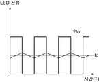
도 5b는 도 1 및 도 2에 도시된 제어부가 평균전류구간에서 부하에 흐르는 구동전류를 나타내는 그래프이다.
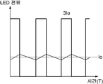
도 5c는 도 1 및 도 2에 도시된 제어부가 평균전류구간에서 부하에 흐르는 구동전류를 나타내는 그래프이다.
도 6는 도 1 및 도 2에 도시된 전원장치의 구동방법을 나타내는 순서도이다.1 is a structural diagram showing a power supply device according to the present invention.
2 is a circuit diagram showing an embodiment of the power supply apparatus shown in FIG.
FIG. 3A is a circuit diagram showing an embodiment of the power supply unit shown in FIG. 1. FIG.
3B is a circuit diagram showing another embodiment of the power supply unit shown in FIG.
4A is a graph showing the operation of the first control module shown in FIGS. 1 and 2. FIG.
FIG. 4B is a graph showing the operation of the first control module shown in FIGS. 1 and 2. FIG.
4C is a graph showing the operation of the second control module shown in FIGS. 1 and 2. FIG.
FIG. 5A is a graph showing the driving current flowing in the load in the constant current section of the control unit shown in FIGS. 1 and 2. FIG.
FIG. 5B is a graph showing a driving current flowing through the load in the average current section of the control unit shown in FIGS. 1 and 2. FIG.
FIG. 5C is a graph showing the driving currents flowing through the load in the average current period of the control unit shown in FIGS. 1 and 2. FIG.
6 is a flowchart showing a driving method of the power supply device shown in Figs. 1 and 2. Fig.
본 발명에 따른 전원장치 및 그의 구동방법의 상기 목적에 대한 기술적 구성을 비롯한 작용효과에 관한 사항은 본 발명의 바람직한 실시예가 도시된 도면을 참조한 아래의 상세한 설명에 의해서 명확하게 이해될 것이다.The matters relating to the operational effects including the technical constitution of the above object of the power supply apparatus and the driving method thereof according to the present invention will be clearly understood by the following detailed description of the preferred embodiments of the present invention with reference to the drawings.
또한, 본 발명을 설명함에 있어서, 관련된 공지 기술에 대한 구체적인 설명이 본 발명의 요지를 불필요하게 흐릴 수 있다고 판단되는 경우 그 상세한 설명은 생략한다. 본 명세서에서 제1, 제2 등의 용어는 하나의 구성요소를 다른 구성요소로부터 구별하기 위해 사용되는 것으로 구성요소가 상기 용어들에 의해 제한되는 것은 아니다.In the following description, well-known functions or constructions are not described in detail since they would obscure the invention in unnecessary detail. In this specification, the terms first, second, etc. are used to distinguish one element from another element, and the element is not limited by these terms.
후술하는 본 발명에 대한 상세한 설명은, 본 발명이 실시될 수 있는 특정 실시예를 예시로서 도시하는 첨부 도면을 참조한다. 이들 실시예는 당업자가 본 발명을 실시할 수 있기에 충분하도록 상세히 설명된다. 본 발명의 다양한 실시예는 서로 다르지만 상호 배타적일 필요는 없음이 이해되어야 한다. 예를 들어, 여기에 기재되어 있는 특정 형상, 구조 및 특성은 일 실시예에 관련하여 본 발명의 정신 및 범위를 벗어나지 않으면서 다른 실시예로 구현될 수 있다. 또한, 각각의 개시된 실시예 내의 개별 구성요소의 위치 또는 배치는 본 발명의 정신 및 범위를 벗어나지 않으면서 변경될 수 있음이 이해되어야 한다. 따라서, 후술하는 상세한 설명은 한정적인 의미로서 취하려는 것이 아니며, 본 발명의 범위는, 적절하게 설명된다면, 그 청구항들이 주장하는 것과 균등한 모든 범위와 더불어 첨부된 청구항에 의해서만 한정된다. 도면에서 유사한 참조부호는 여러 측면에 걸쳐서 동일하거나 유사한 기능을 지칭한다.The following detailed description of the invention refers to the accompanying drawings, which illustrate, by way of illustration, specific embodiments in which the invention may be practiced. These embodiments are described in sufficient detail to enable those skilled in the art to practice the invention. It should be understood that the various embodiments of the present invention are different, but need not be mutually exclusive. For example, certain features, structures, and characteristics described herein may be implemented in other embodiments without departing from the spirit and scope of the invention in connection with an embodiment. It is also to be understood that the position or arrangement of the individual components within each disclosed embodiment may be varied without departing from the spirit and scope of the invention. The following detailed description is, therefore, not to be taken in a limiting sense, and the scope of the present invention is to be limited only by the appended claims, along with the full scope of equivalents to which such claims are entitled, if properly explained. In the drawings, like reference numerals refer to the same or similar functions throughout the several views.
이하에서는, 본 발명이 속하는 기술분야에서 통상의 지식을 가진 자가 본 발명을 용이하게 실시할 수 있도록 하기 위하여, 본 발명의 바람직한 실시예들에 관하여 첨부된 도면을 참조하여 상세히 설명하기로 한다.Hereinafter, preferred embodiments of the present invention will be described in detail with reference to the accompanying drawings, so that those skilled in the art can easily carry out the present invention.
도 1은 본 발명에 따른 전원장치를 나타내는 구조도이다. 1 is a structural diagram showing a power supply device according to the present invention.
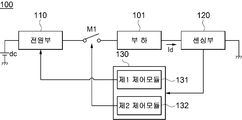
도 1을 참조하면, 전원장치(100)는 부하(101)로 구동전류(Id)를 공급하는 전원부(110), 구동전류(Id)의 크기를 감지하는 센싱부(120), 온오프시간을 조절하여 구동전류(Id)의 흐름을 제어하는 제1스위치(M1), 및 센싱부(120)에서 감지된 구동전류(Id)의 크기에 대응하여 정전류구동과 평균전류구동으로 구분하여 동작하며, 정전류구동에서는 구동전류(Id)의 크기가 기설정된 소정값이 되도록 전원부(110)를 제어하고, 평균전류구동에서는 온오프시간을 조절하여 구동전류(Id) 평균 크기가 기설정된 소정값이 되도록 하는 제어부(130)를 포함할 수 있다. 1, the
전원부(110)는 직류전원(dc)으로부터 전원을 공급받아 소정의 전압을 출력하고 부하(101)에 구동전류(Id)가 전달되도록 할 수 있다. 직류전원(dc)는 교류전원을 정류한 전원일 수 있다. 전원부(110)에서 출력될 수 있는 전압은 소정의 범위 내이며, 부하(101)의 소비전력이 전원부(110)에서 출력되는 전압의 소정 범위 내에 있으면, 전원부(110)에서 부하(101)로 전달되는 구동전류(Id)의 크기가 기설정된 크기로 일정하게 흘러 부하(101)가 정상적인 동작을 할 수 있다. 하지만, 부하(101)의 소비전력이 전원부(110)에서 출력되는 전압의 소정 범위보다 작은 경우 전원부(110)에서 부하(101)로 전달되는 구동전류(Id)의 크기는 기 설정된 크기 보다 더 크게 흐르게 되어 부하(101)가 정상적인 동작을 할 수 없다. 따라서, 전원장치(100)의 출력전압 범위를 넓게 하여 다양한 부하(101)에 적용시킬 필요가 있다. 이를 위해 전원부(110)는 정전류구동과 평균전류구동으로 구분하여 동작할 수 있다. 정전류구동은 구동전류(Id)의 크기가 기설정된 소정값을 유지하도록 하도록 하는 것일 수 있고 평균전류구동은 구동전류(Id)의 평균이 기설정된 소정값을 유지하도록 하는 것일 수 있다. 그리고, 정전류구동은 소비전력이 전원부(110)에서 출력되는 전압 범위 내에 있는 부하(101)가 전원부(110)에 연결되면 동작하고, 평균전류구동은 소비전력이 전원부(110)에서 출력되는 전압 범위 밖에 있는 부하(101)가 전원부(110)에 연결되면 동작될 수 있다. The
센싱부(120)는 부하(101)에 흐른 구동전류(Id)의 크기를 감지할 수 있다. 센싱부(120)는 감지한 구동전류(Id)의 크기를 제어부(130)에 전달할 수 있다. The
제1스위치(M1)는 전원부(110)와 센싱부(120) 사이에 연결되고, 턴온되면 전원부(110)와 센싱부(120)를 연결하여 구동전류(Id)가 부하(101)에 흐르도록 하고 턴오프되면 전원부(110)와 센싱부(120)를 차단하여 구동전류(Id)가 부하(101)에 흐르지 못하도록 할 수 있다. 따라서, 제1스위치(M1)의 온오프시간을 조절하여 부하(101)에 공급되는 구동전류(Id)의 양을 조절할 수 있다. 제1스위치(M1)의 턴온/턴오프는 제어부(130)에서 조절할 수 있다. 여기서, 제1스위치(M1)는 전원부(110)와 센싱부(120) 사이에 연결되어 있는 것으로 도시되어 있으나 이에 한정되는 것은 아니며, 전원부(110)에서 생성된 전류가 부하(101)에 흐르지 못하게 할 수 있는 위치에 연결될 수 있다. 여기서 제1스위치(M1)는 FET로 도시되어 있지만 이에 한정되는 것은 아니며, BJT, JFET 등 스위치로 사용될 수 있는 소자일 수 있다. The first switch M1 is connected between the
제어부(130)는 센싱부(120)로부터 구동전류(Id)의 크기를 감지한 결과를 전달받아 제어동작을 수행할 수 있다. 제어부(130)는 센싱부(120)로부터 감지된 구동전류(Id)의 크기가 기설정된 소정값이면 전원부(110)가 정전류구동으로 동작할 수 있도록 하고 센싱부(120)로부터 감지된 구동전류(Id)의 크기가 기설정된 소정값을 초과하면 전원부(110)가 평균전류구동으로 동작할 수 있도록 제어할 수 있다. 여기서, 정전류구동과 평균전류구동을 구분하는 기준인 구동전류(Id)의 기설정된 소정값은 일정한 범위를 가질 수 있어 센싱부(120)에서 감지된 구동전류의 크기가 기설정된 소정값보다 일정 범위 내에서 작거나 큰 경우는 제어부(130)는 기설정된 소정값인 경우로 판단하여 정전류구동을 수행할 수 있다. 일 실시예에 있어서, 제어부(130)는 정전류구동과 평균전류구동에서 전원부(110)를 제어하여 구동전류(Id)를 생성하는 제1제어모듈(131)과, 센싱부(120)에서 감지된 구동전류(Id)의 크기가 기 설정된 소정값을 초과하는 경우, 제1스위치(M1)의 온오프시간을 조절하여 구동전류(Id)의 크기의 평균이 기설정된 소정값이 되도록 조절하는 제2제어모듈(132)을 포함할 수 있다. The
도 2는 도 1에 도시된 전원장치의 일 실시예를 나타내는 회로도이다. 2 is a circuit diagram showing an embodiment of the power supply apparatus shown in FIG.
도 2를 참조하면, 전원장치(100a)는 부하(101a)로 구동전류(Id)를 공급하는 전원부(110a), 구동전류(Id)의 크기를 센싱하는 센싱부(120a), 온오프시간을 조절하여 구동전류(Id)의 흐름을 제어하는 제1스위치(M1a), 및 전원부(110a)에서 부하(101a)로 공급하는 구동전류(Id)의 크기와 제1스위치(M1a)의 스위칭동작을 제어하고 센싱부(120a)에서 감지된 결과에 대응하여 전원부(110a)를 제어함으로써, 전원부(110a)에서 공급하는 구동전류(Id)의 크기를 조절하되, 구동전류(Id)의 크기가 기 설정된 소정값을 초과하는 경우, 제1스위치(M1a)의 온오프시간을 조절하여 구동전류(Id)의 크기의 평균이 기설정된 소정값이 되도록 제어하는 제어부(130a)를 포함할 수 있다. 2, the
전원부(110a)는 인덕터(L1)와, 인덕터(L1)에 연결되어 있는 제2스위치(M2)를 포함할 수 있다. 전원부(110)는 제2스위치(M2)의 턴온/턴오프에 대응하여 인덕터(L1)에 기전력을 형성하고 형성된 기전력에 대응하여 소정의 전압과 구동전류(Id)를 생성하여 부하(101a)에 전달할 수 있다. 일 실시예에 있어서, 전원부(110)는 플라이백 컨버터일 수 있으며, 전원부(110)는 직류전원(dc), 직류전원(dc)에 연결되어 있는 1차측 인덕터(L1), 1차측 인덕터(L1)에 연결되어 1차측 인덕터(L1)에 흐르는 전류의 흐름을 조절할 수 있는 제2스위치(M2), 1차측 인덕터(L1)에서 발생된 기전력을 전달받아 구동전류를 생성하는 2차측 인덕터(L2)를 포함할 수 있다. 하지만, 전원부(110)는 이에 한정되는 것은 아니며, DC-DC 컨버터 등 스위치모드 전원장치일 수 있다. 전원부(110a)에 연결되는 부하(101a)는 LED 모듈일 수 있다. LED 모듈은 복수의 발광소자를 포함할 수 있고 복수의 발광소자는 직렬 및/또는 병렬로 연결되어 구동전류(Id)에 대응하여 빛을 발광할 수 있다. LED 모듈의 소비전력은 발광소자의 개수, 각 발광소자의 소비전력에 따라 다른 값을 가질 수 있다. LED 모듈의 소비전력은 LED 모듈의 Vf(LED Forward Voltage)라고 할 수 있다. The
또한, 전원부(110a)에 연결되는 LED 모듈 등의 부하(101a)의 소비전력에 대응하여 전원부(110a)에서 출력되는 전압이 결정될 수 있다. 그리고, 전원부(110a)는 제1제어신호를 전달받아 제2스위치(M2)의 턴온/턴오프가 조절될 수 있고 전원부(110a)에서 생성되는 소정의 전압은 일정범위를 가질 수 있다. 제1제어신호는 듀티비 변화에 따라 제2스위치(M2)의 턴온/턴오프를 조절할 수 있고 주파수 변화에 따라 제2스위치(M2)의 턴온/턴오프를 조절할 수 있다. In addition, the voltage output from the
센싱부(120a)는 저항(Rs)을 포함할 수 있고, 저항(Rs)에 생성된 전압을 감지하여 저항(Rs)에 흐르는 구동전류(Id)의 크기를 감지할 수 있다. 그리고, 센싱부(120a)는 감지한 구동전류(Id)의 크기를 제어부(130a)에 전달할 수 있다.The sensing unit 120a may include a resistor Rs and sense the voltage generated in the resistor Rs to sense the magnitude of the driving current Id flowing through the resistor Rs. The sensing unit 120a can transmit the magnitude of the sensed driving current Id to the
제1스위치(M1a)는 일단이 부하(101a)에 연결되고 타단이 센싱부(120a)에 연결되며, 제어부(130a)에 의해 턴온 또는 턴오프가 결정될 수 있다. 제1스위치(M1a)의 연결관계는 일단이 전원부(110)에 연결되고 타단이 부하(101)에 연결되어 있는 도 1의 제1스위치(M1)와 차이가 있다. 이러한 차이점은 부하에 흐르는 전류를 스위칭할 수 있는 스위치의 위치가 다양할 수 있음을 나타낸 것이다. 또한, 제1스위치(M1a)는 모스(MOS)트랜지스터일 수 있고, 소스전극이 부하(101a)에 연결되고 드레인전극이 센싱부(120a)에 연결되며 게이트전극이 제어부(130a)에 연결될 수 있다. 그리고, 게이트전극에 인가되는 전압에 대응하여 제1스위치(M1a)의 턴온 또는 턴오프가 결정될 수 있다. 또한, 제1스위치(M1a)는 모스 트랜지스터로 한정되는 것은 아니며 FET(Field Effect Transistor), BJT(Bipolar Junction Transistor), JFET(Junction Field Effect Transistor) 등 다양한 트랜지스터를 사용할 수 있다. One end of the first switch M1a is connected to the
제어부(130a)는 제1제어모듈(131a)과 제2제어모듈(132a)을 포함하고, 제1제어모듈(131a)에서 제2스위치(M2)의 턴온 또는 턴오프를 결정하는 제1제어신호를 출력할 수 있고 제2제어모듈(132a)에서 제1스위치(M1)의 턴온 또는 턴오프를 결정하는 제2제어신호를 출력할 수 있다. 제1제어모듈(131a)은 제2스위치(M2)의 턴온 또는 턴오프를 결정하기 위해 제2스위치(M2)의 턴온시간과 턴오프시간의 비인 듀티비를 조절하거나 제2스위치(M2)의 턴온/턴오프의 주기를 변경하는 주파수를 조절할 수 있는 제1제어신호를 출력할 수 있다. 그리고, 제2제어모듈(132a)은 센싱부(120a)에서 감지된 전류의 크기와 기준전류를 비교하여 구동전류(Id)의 크기가 기설정된 소정값을 초과하는지를 판단할 수 있다. 또한, 제2제어모듈(132a)은 구동전류(Id)의 크기가 기준전류의 크기를 초과한 것으로 판단하면, 구동전류(Id)의 크기에 대응하여 온오프시간을 조절하는 제2제어신호를 출력할 수 있다. 이를 위해 제2제어모듈(132a)은 부(-)입력단으로 센싱부(120a)에서 감지된 구동전류(Id)에 대응하는 전압을 입력받고 정(+)입력단으로 기준전류에 대응하는 전압을 입력받는 비교기(1321a)와, 정(+)입력단으로 비교기(1321a)의 출력신호를 입력받고 부(-)입력단으로 톱니파와 같은 소정의 펄스를 입력받아 비교기(1321a)의 출력신호에 대응하여 턴온신호와 턴오프신호의 비인 듀티비를 조절할 수 있는 제2제어신호를 출력하는 신호출력기(1322a)를 포함할 수 있다. 또한, 제2제어모듈(132a)은 앤드게이트(1323a)를 더 포함하고, 앤드게이트(1323a)에서 제2제어신호와 디밍신호를 연산하여 출력할 수 있어 제1스위치(M1a)의 온오프시간을 조절하여 부하에 공급되는 전류를 조절할 수 있다. 부하(101a)가 LED 모듈인 경우 제2제어신호와 디밍신호를 제어하여 LED 모듈의 밝기를 조절할 수 있다. The
도 3a는 도 1에 도시된 전원부의 일 실시예를 나타내는 회로도이다. FIG. 3A is a circuit diagram showing an embodiment of the power supply unit shown in FIG. 1. FIG.
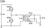
도 3a을 참조하면, 전원부(110b)는 직류전원(dc)에 제1트랜지스터(M2a)와 제2트랜지스터(M2b)가 직렬로 연결된다. 제1트랜지스터(M2a)와 제2트랜지스터(M2b)는 각각 도 1의 제1제어모듈(131)로부터 제어신호를 전달받아 교번적으로 턴온/턴오프될 수 있다. 그리고, 제1트랜지스터(M2a)와 제2트랜지스터(M2b)의 스위칭 동작에 의해 일차측인덕터(L1a)에 흐르는 전류의 방향이 변경될 수 있다. 그리고, 일차측인덕터(L1a)에 흐르는 전류의 방향에 대응하여 제1이차측인덕터(L21a)와 제2이차측인덕터(L22a)에 각각 전류가 유도될 수 있다. 그리고, 유도된 전류는 부하에 공급될 수 있다. Referring to FIG. 3A, in the
도 3b는 도 1에 도시된 전원부의 다른 일 실시예를 나타내는 회로도이다.3B is a circuit diagram showing another embodiment of the power supply unit shown in FIG.
도 3b를 참조하면, 전원부(110c)는 직류전원(dc)에 제1트랜지스터 내지 제4트랜지스터(M21 내지 M24)가 브리지 형태로 연결된다. 제1트랜지스터 내지 제4트랜지스터(M21 내지 M24)는 각각 도 1의 제1제어모듈(131)로부터 제어신호를 전달받아 스위칭동작을 하여, 제1트랜지스터(M21)와 제4트랜지스터(M24)가 턴온되면 제2트랜지스터(M22)와 제3트랜지스터(M23)가 턴오프되고, 제1트랜지스터(M21)와 제4트랜지스터(M22)가 턴오프되면 제2트랜지스터(M22)와 제3트랜지스터(M23)가 턴온될 수 있다. 또한, 제1트랜지스터 내지 제4트랜지스터(M21 내지 M24)는 서로 다른 위상차를 갖고 턴온/턴오프될 수 있다. 그리고, 제1트랜지스터 내지 제4트랜지스터(M21 내지 M24)의 스위칭 동작에 의해 일차측인덕터(L1b)에 흐르는 전류의 방향이 변경될 수 있다. 그리고, 일차측인덕터(L1b)에 흐르는 전류의 방향에 대응하여 제1이차측인덕터(L21b)와 제2이차측인덕터(L22b)에 각각 전류가 유도될 수 있다. 그리고, 유도된 전류는 부하에 공급될 수 있다.Referring to FIG. 3B, the
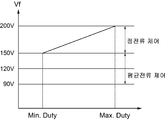
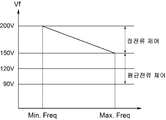
도 4a와 도 4b는 도 1 및 도 2에 도시된 제1제어모듈의 동작을 나타내는 그래프이고, 도 4c는 도 1 및 도 2에 도시된 제2제어모듈의 동작을 나타내는 그래프이다.FIGS. 4A and 4B are graphs showing the operation of the first control module shown in FIGS. 1 and 2. FIG. 4C is a graph showing the operation of the second control module shown in FIGS.
도 4a 및 도 4b에 도시되어 있는 것과 같이, 제1제어모듈(131,131a)은 듀티비를 조절하거나 주파수를 조절하여 정전류제어를 할 수 있다. 예를 들어, 전원부(110,110a)에서 출력전압의 범위가 150~200V 사이일 때, 듀티비를 조절하는 경우 소비전력이 150V인 LED 모듈 등의 부하(101,101a)가 연결되면 듀티비가 최소가 되도록 하여 소비전력이 150V인 부하(101,101a)에 맞도록 동작하고 소비전력이 200V인 LED 모듈 등의 부하(101,101a)가 연결되면 듀티비가 최대가 되도록 하여 소비전력이 200V인 부하(101,101a)에 맞도록 동작할 수 있다. 이때, 듀티비는 제2스위치(M2)의 온시간과 오프시간의 비를 의미하며, 듀티비가 최소인 것은 온시간이 짧고 오프시간이 긴 경우를 의미하고 듀티비가 최대인 것은 온시간이 길고 오프시간이 짧은 경우를 의미할 수 있다. 또한, 듀티비 최대는 제2스위치(M2)가 온상태를 유지하는 경우를 의미할 수 있다. 그리고, 주파수를 조절하는 경우 소비전력이 150V인 LED 모듈 등의 부하(101,101a)가 연결되면 제2스위치(M2)의 스위칭 주파수가 최대가 되도록 하고 소비전력이 200V인 LED 모듈 등의 부하(101,101a)가 연결되면 제2스위치(M2)의 스위칭 주파수가 최소가 되도록 할 수 있다. 그리고, 전원부(110,110a)에서 출력전압 범위 밖인 소비전력이 90V 또는 120V 인 부하(101,101a)가 연결되면 제1제어모듈(131,131a)은 듀티비를 조절하는 경우 150V의 부하(101,101a)가 연결되었을 때와 마찬가지로 듀티비를 최소로 유지하도록 할 수 있고 주파수를 조절하는 경우 150V가 연결되었을 때와 마찬가지로 제2스위치(M2)의 스위칭 주파수가 최대가 되도록 할 수 있다. As shown in FIGS. 4A and 4B, the
그리고, 도 4c에 도시되어 있는 것과 같이, 제2제어모듈(132,132a)은 듀티비를 조절하여 평균전류제어를 할 수 있다. 보다 구체적으로 설명하면, 제2제어모듈(132,132a)은 전원부(110,110a)에서 출력전압의 범위가 150~200V 사이일 때, 소비전력이 150~200V 범위 내의 부하가 연결되면 정전류제어를 위해 제1스위치(M1,M1a)의 듀티비는 100%일 수 있다. 듀티비가 100%인 것은 제1스위치(M1,M1a)가 턴온상태를 유지하는 것일 수 있다. 그리고, 소비전력이 90V 또는 120V 등 전원부(110)에서 출력전압의 범위 밖의 부하가 연결되면 제1스위치(M1,M1a)의 듀티비를 조절하여 구동전류의 평균이 기설정된 소정값이 될 수 있도록 평균전류제어를 할 수 있다. As shown in FIG. 4C, the
도 5a는 도 1 및 도 2에 도시된 제어부가 정전류구간에서 부하에 흐르는 구동전류를 나타내는 그래프이고, 도 5b 및 도 5c는 도 1 및 도 2에 도시된 제어부가 평균전류구간에서 부하에 흐르는 구동전류를 나타내는 그래프이다. FIG. 5A is a graph showing the driving current flowing through the load in the constant current section of the control unit shown in FIGS. 1 and 2, FIGS. 5B and 5C are graphs showing the driving current Fig.
도 5a에 도시되어 있는 것과 같이, 센싱부(120,120a)에서 센싱한 구동전류의 크기가 기설정된 소정값(Io)인 경우에는 제1제어모듈(131,131a)만 동작을 하고 제2제어모듈(132,132a)은 동작을 하지 않아 제1스위치(M1,M1a)는 턴온상태를 유지하고 있기 때문에 LED 모듈 등의 부하(101)에 흐르는 구동전류(Id)의 크기는 기설정된 소정값인 Io의 크기를 갖도록 일정하게 유지할 수 있다. 하지만, 도 5b에 도시되어 있는 것과 같이, 센싱부(120,120a)에서 감지된 구동전류(Id)의 크기가 기설정된 소정값의 두배인 2Io인 경우에는 제1스위치(M1,M1a)의 온오프시간을 조절하여 구동전류(Id)가 흐르는 구간과 흐르지 않는 구간이 나타나도록 할 수 있다. 이때, 감지된 구동전류(Id)의 크기가 기설정된 소정값의 두배이기 때문에 듀티비를 50%로 설정하여 제어하면 평균전류가 기설정된 소정값인 Io의 크기를 가질 수 있다. 또한, 도 5c에 도시되어 있는 것과 같이 센싱부(120,120a)에서 감지된 구동전류(Id)의 크기가 기설정된 소정값의 세배인 3Io인 경우에 역시 제1스위치(M1,M1a)의 온오프시간을 조절하여 구동전류(Id)가 흐르는 구간과 흐르지 않는 구간이 나타나도록 할 수 있다. 이때, 감지된 구동전류(Id)의 크기가 기설정된 소정값의 세배이기 때문에 듀티비를 33%로 설정하여 제어하면 평균전류가 기설정된 소정값인 Io의 크기를 가질 수 있다. 여기서, 구동전류(Id)의 크기와 듀티비는 예시적인 것이며 이에 한정되는 것은 아니다. 5A, when the magnitude of the driving current sensed by the
도 6은 도 1 및 도 2에 도시된 전원장치의 구동방법을 나타내는 순서도이다. 6 is a flowchart showing a method of driving the power supply apparatus shown in Figs. 1 and 2. Fig.
도 6을 참조하면, 전원장치(100)의 구동방법은 LED 모듈 등의 부하(101)에 흐르는 구동전류를 센싱부(120,120a)에서 감지할 수 있다.(S500) 전원장치(100)는 인덕터(L1)에 흐르는 전류를 제어함으로써 구동전류를 생성하는 전원부(110)를 포함하고 있고, 인덕터(L1)에 흐르는 전류에 대응하여 구동전류(Id)가 부하(101)로 공급될 수 있다. 또한, 센싱부(120)는 부하(101,101a)로 공급되는 구동전류(Id)를 감지할 수 있다. 부하(101,101a)는 LED 모듈일 수 있다. 6, the driving method of the
그리고, 감지된 구동전류(Id)에 대응하여 인덕터에 흐르는 전류의 양을 조절함으로써, 구동전류의 크기를 조절할 수 있다.(S510) 부하(101,101a)에 흐르는 구동전류(Id)의 양을 조절하기 위해서 인덕터(L1)에 연결되어 있는 제2스위치(M2)의 턴온 또는 턴오프 동작을 제어하여 인덕터(L1)에 흐르는 전류의 양을 조절하고 이로 인해, 구동전류의 크기가 조절될 수 있다. 제2스위치(M2)의 턴온 또는 턴오프 동작은 제어부(130,130a)에서 센싱부(120,120a)에서 감지된 구동전류(Id)에 대응하여 제1제어신호를 출력하여 제어할 수 있다. 제1제어신호는 제2스위치(M2)의 턴온시간과 턴오프 시간의 비율을 조절하는 듀티비제어와, 턴온시간과 턴오프 시간의 주기를 변경하는 주파수제어 중 어느 하나를 이용할 수 있고, 제2제어신호는 감지된 구동전류(Id)의 크기에 따라 듀티비를 조절하거나 주파수를 변경하여 제2스위치(M2)의 턴온 또는 턴오프 동작이 제어될 수 있도록 할 수 있다. The magnitude of the driving current Id can be adjusted by adjusting the amount of the current flowing through the inductor in accordance with the sensed driving current Id at step S510. The turn-on or turn-off operation of the second switch M2 connected to the inductor L1 is controlled to adjust the amount of the current flowing in the inductor L1, thereby adjusting the magnitude of the drive current. The turn-on or turn-off operation of the second switch M2 can be controlled by outputting a first control signal corresponding to the drive current Id detected by the
또한, 감지된 구동전류(Id)의 크기가 기 설정된 소정값을 초과한 것으로 판단되면, 구동전류의 흐름을 온오프하여 구동전류의 크기의 평균을 기설정된 소정갑이 되도록 할 수 있다.(S520) 구동전류의 흐름을 온오프하는 것은 제1스위치(M1,M1a)의 온오프시간을 조절함으로써 달성할 수 있다. 감지된 구동전류(Id)의 크기가 기 설정된 소정값을 초과하면 제2스위치(M2)의 턴온 또는 턴오프 동작 만으로 구동전류(Id)의 크기를 기설정된 소정값으로 조절할 수 없다. 이를 방지하기 위해 부하(101,101a)와 센싱부(120,120a) 사이에 연결되어 있는 제1스위치(M1,M1a)의 온오프시간을 조절하여 부하(101,101a)에 흐르는 구동전류(Id)의 평균이 기 설정된 소정값이 될 수 있도록 할 수 있다. 제1스위치(M1,M1a)의 턴온 또는 턴오프 동작은 제2제어신호에 의해 조절될 수 있고 제1제어신호는 제1스위치(M1,M1a)의 턴온시간과 턴오프 시간의 비율을 조절하여 구동전류(Id)의 평균이 기설정된 소정값이 되도록 할 수 있다. 기설정된 소정값은 전원부(110,110a)의 출력전압 범위에 맞는 소비전력을 갖는 부하가 연결되어 있는 경우 부하에 흐르는 전류의 크기일 수 있다. In addition, if it is determined that the magnitude of the sensed driving current Id exceeds the preset predetermined value, the average of the magnitude of the driving current can be made to be a predetermined predetermined number by turning on and off the driving current flow. ) Turning on / off the flow of the driving current can be achieved by adjusting the ON / OFF times of the first switches M1 and M1a. The magnitude of the driving current Id can not be adjusted to a predetermined value only by turning on or off the second switch M2 if the magnitude of the sensed driving current Id exceeds a preset predetermined value. In order to prevent this, the on / off time of the first switches M1 and M1a connected between the
본 명세서의 청구항들에서, 특정 기능을 수행하기 위한 수단으로서 표현된 요소는 특정 기능을 수행하는 임의의 방식을 포괄하고, 이러한 요소는 특정 기능을 수행하는 회로 요소들의 조합, 또는 특정 기능을 수행하기 위한 소프트웨어를 수행하기 위해 적합한 회로와 결합된, 펌웨어, 마이크로코드 등을 포함하는 임의의 형태의 소프트 웨어를 포함할 수 있다.In the claims hereof, the elements depicted as means for performing a particular function encompass any way of performing a particular function, such elements being intended to encompass a combination of circuit elements that perform a particular function, Microcode, etc., coupled with suitable circuitry to perform the software for the
본 명세서에서 본 발명의 원리들의 '일 실시예' 등과 이런 표현의 다양한 변형들의 지칭은 이 실시예와 관련되어 특정 특징, 구조, 특성 등이 본 발명의 원리의 적어도 하나의 실시예에 포함된다는 것을 의미한다. 따라서, 표현 '일 실시예에서'와, 본 명세서 전체를 통해 개시된 임의의 다른 변형례들은 반드시 모두 동일한 실시예를 지칭하는 것은 아니다. Reference throughout this specification to " one embodiment ", etc. of the principles of the invention, and the like, as well as various modifications of such expression, are intended to be within the spirit and scope of the appended claims, it means. Thus, the appearances of the phrase " in one embodiment " and any other variation disclosed throughout this specification are not necessarily all referring to the same embodiment.
본 명세서에서 '연결된다' 또는 '연결하는' 등과 이런 표현의 다양한 변형들의 지칭은 다른 구성요소와 직접적으로 연결되거나 다른 구성요소를 통해 간접적으로 연결되는 것을 포함하는 의미로 사용된다. 또한 본 명세서에서 단수형은 문구에서 특별히 언급하지 않는 한 복수형도 포함한다. 아울러 본 명세서에서 사용되는 '포함한다' 또는 '포함하는'으로 언급된 구성요소, 단계, 동작 및 소자는 하나 이상의 다른 구성요소, 단계, 동작, 소자 및 장치의 존재 또는 추가를 의미한다.It will be understood that the term " connected " or " connecting ", and the like, as used in the present specification are intended to include either direct connection with other components or indirect connection with other components. Also, the singular forms in this specification include plural forms unless the context clearly dictates otherwise. Also, components, steps, operations, and elements referred to in the specification as " comprises " or " comprising " refer to the presence or addition of one or more other components, steps, operations, elements, and / or devices.
100: 전원장치
101: 부하
110: 전원부
120: 센싱부
130: 제어부
131: 제1제어모듈
131: 제2제어모듈
M1: 제1스위치
Id: 구동전류
dc: 직류전원100: power supply 101: load
110: power supply unit 120: sensing unit
130: control unit 131: first control module
131: second control module M1: first switch
Id: drive current dc: DC power
Claims (20)
상기 구동전류의 크기를 감지하는 센싱부;
온오프시간을 조절하여 상기 구동전류의 흐름을 제어하는 제1스위치; 및
상기 센싱부에서 감지된 상기 구동전류의 크기에 대응하여 정전류구동과 평균전류구동으로 구분하여 동작하며, 상기 정전류구동에서는 상기 구동전류의 크기가 기설정된 소정값이 되도록 상기 전원부를 제어하고, 상기 평균전류구동에서는 상기 온오프시간을 조절하여 상기 구동전류의 평균 크기가 기설정된 소정값이 되도록 하는 제어부를 포함하는 전원장치.A power supply for supplying a driving current to the load;
A sensing unit sensing a magnitude of the driving current;
A first switch for controlling the flow of the driving current by adjusting an on / off time; And
Wherein the control unit controls the power source unit so that the magnitude of the driving current is equal to a predetermined value in the constant current driving mode and operates by dividing the constant current driving and the average current driving according to the magnitude of the driving current sensed by the sensing unit, And a controller for adjusting the on / off time so that the average magnitude of the driving current becomes a predetermined value in current driving.
상기 제어부는, 상기 정전류구동과 상기 평균전류구동에서 상기 전원부를 제어하여 상기 구동전류를 생성하는 제1제어모듈과, 상기 센싱부에서 감지된 상기 구동전류의 크기가 기 설정된 소정값을 초과하는 경우, 상기 온오프시간을 조절하여 상기 구동전류의 크기의 평균이 상기 기설정된 소정값이 되도록 조절하는 제2제어모듈을 포함하는 전원장치.The method according to claim 1,
Wherein the control unit includes a first control module for controlling the power source unit in the constant current drive and the average current drive to generate the drive current, and a control unit for controlling the drive current to be supplied to the drive unit when the magnitude of the drive current sensed by the sensing unit exceeds a preset predetermined value And a second control module for adjusting the on / off time to adjust the average of the magnitude of the driving current to a predetermined value.
상기 전원부는 인덕터와 상기 인덕터에 연결되어 있는 제2스위치를 포함하고, 상기 제1제어모듈은 상기 제2스위치의 턴온 또는 턴오프를 조절하여 상기 인덕터에 흐르는 전류의 크기를 조절하는 제1제어신호를 출력하는 전원장치.3. The method of claim 2,
The power supply unit includes an inductor and a second switch connected to the inductor. The first control module controls a turn-on or a turn-off of the second switch to control a magnitude of a current flowing in the inductor, .
상기 제1제어신호는 상기 센싱부에서 감지된 상기 구동전류의 크기에 대응하여 듀티비가 조절되는 전원장치.The method of claim 3,
Wherein the duty ratio of the first control signal is adjusted corresponding to the magnitude of the driving current sensed by the sensing unit.
상기 제1제어신호는 상기 센싱부에서 감지된 상기 구동전류의 크기에 대응하여 주파수가 조절되는 전원장치.The method of claim 3,
Wherein the frequency of the first control signal is adjusted in accordance with the magnitude of the driving current sensed by the sensing unit.
상기 제2제어모듈은 상기 센싱부에서 감지된 구동전류의 크기와 기준전류를 비교하여 상기 구동전류의 크기가 기설정된 소정값을 초과하는지를 판단하는 전원장치.3. The method of claim 2,
Wherein the second control module compares the magnitude of the driving current sensed by the sensing unit with a reference current to determine whether the magnitude of the driving current exceeds a preset predetermined value.
상기 제2제어모듈은 상기 구동전류의 크기가 상기 기준전류의 크기를 초과한 것으로 판단하면, 상기 구동전류의 크기에 대응하여 상기 온오프시간을 조절하는 제2제어신호를 출력하는 전원장치.The method according to claim 6,
And the second control module outputs a second control signal for adjusting the on / off time according to the magnitude of the driving current when it is determined that the magnitude of the driving current exceeds the magnitude of the reference current.
상기 제2제어모듈은,
부(-)입력단으로 상기 센싱부에서 감지된 구동전류에 대응하는 전압을 입력받고 정(+)입력단으로 기준전류에 대응하는 전압을 입력받는 비교기와, 정(+)입력단으로 상기 비교기의 출력신호를 입력받고 부(-)입력단으로 소정의 펄스를 입력받아 상기 비교기의 출력신호에 대응하여 듀티비가 조절되는 제2제어신호를 출력하는 신호출력기를 포함하는 전원장치.3. The method of claim 2,
Wherein the second control module comprises:
A comparator for receiving a voltage corresponding to the driving current sensed by the sensing unit and inputting a voltage corresponding to a reference current to a positive input terminal of the comparator, And a signal output unit for receiving a predetermined pulse to a negative input terminal and outputting a second control signal whose duty ratio is adjusted in accordance with the output signal of the comparator.
상기 구동전류의 크기를 감지하는 센싱부;
온오프시간을 조절하여 상기 구동전류의 흐름을 제어하는 제1스위치; 및
상기 전원부에서 부하로 공급하는 상기 구동전류의 크기와 상기 제1스위치의 스위칭동작을 제어하고 상기 센싱부에서 감지된 결과에 대응하여 상기 전원부를 제어함으로써, 상기 전원부에서 공급하는 상기 구동전류의 크기를 조절하되, 상기 구동전류의 크기가 기설정된 소정값을 초과하는 경우, 상기 제1스위치의 온오프시간을 조절하여 상기 구동전류의 크기의 평균이 상기 기설정된 소정값이 되도록 제어하는 제어부를 포함하는 전원장치.A power supply for supplying a driving current to the load;
A sensing unit sensing a magnitude of the driving current;
A first switch for controlling the flow of the driving current by adjusting an on / off time; And
The control unit controls the magnitude of the driving current supplied from the power source unit to the load and the switching operation of the first switch and controls the power source unit according to the result detected by the sensing unit, Off time of the first switch to control the average of the magnitude of the driving current to be the preset predetermined value when the magnitude of the driving current exceeds a preset predetermined value, Power supply.
상기 제어부는, 상기 센싱부에서 감지된 결과에 대응하여 상기 전원부를 제어함으로써, 상기 전원부에서 공급하는 상기 구동전류의 크기를 조절하는 제1제어모듈과 상기 구동전류의 크기가 기 설정된 소정값을 초과하는 경우, 상기 스위치의 온오프시간을 제어하여 상기 구동전류의 크기의 평균이 상기 기설정된 소정값이 되도록 제어하는 제2제어모듈을 포함하는 전원장치.10. The method of claim 9,
The control unit may include a first control module for controlling the power supply unit in response to a result sensed by the sensing unit and adjusting a magnitude of the driving current supplied from the power supply unit, Off time of the switch to control the average of the magnitude of the drive current to be the predetermined value.
상기 전원부는 인덕터와 상기 인덕터에 연결되어 있는 제2스위치를 포함하고, 상기 제1제어모듈은 상기 제2스위치의 턴온 또는 턴오프를 조절하여 상기 인덕터에 흐르는 전류의 크기를 조절하는 제1제어신호를 출력하는 전원장치.11. The method of claim 10,
The power supply unit includes an inductor and a second switch connected to the inductor. The first control module controls a turn-on or a turn-off of the second switch to control a magnitude of a current flowing in the inductor, .
상기 제1제어신호는 상기 구동전류의 크기에 대응하여 듀티비가 조절되는 전원장치.12. The method of claim 11,
Wherein the first control signal has a duty ratio adjusted in accordance with a magnitude of the driving current.
상기 제1제어신호는 상기 구동전류의 크기에 대응하여 주파수가 조절되는 전원장치.12. The method of claim 11,
Wherein the first control signal is adjusted in frequency corresponding to the magnitude of the driving current.
상기 제2제어모듈은 상기 센싱부에서 감지된 전류의 크기와 기준전류를 비교하여 상기 구동전류의 크기가 기설정된 소정값을 초과하는지를 판단하는 전원장치.11. The method of claim 10,
Wherein the second control module compares the magnitude of the current sensed by the sensing unit with a reference current to determine whether the magnitude of the driving current exceeds a preset predetermined value.
상기 제2제어모듈은 상기 구동전류의 크기가 상기 기준전류의 크기를 초과한 것으로 판단하면, 상기 구동전류의 크기에 대응하여 상기 온오프시간을 조절하는 제2제어신호를 출력하는 전원장치.15. The method of claim 14,
And the second control module outputs a second control signal for adjusting the on / off time according to the magnitude of the driving current when it is determined that the magnitude of the driving current exceeds the magnitude of the reference current.
상기 제2제어모듈은,
부(-)입력단으로 상기 센싱부에서 감지된 구동전류에 대응하는 전압을 입력받고 정(+)입력단으로 기준전류에 대응하는 전압을 입력받는 비교기와, 정(+)입력단으로 비교기의 출력신호를 입력받고 부(-)입력단으로 소정의 펄스를 입력받아 상기 비교기의 출력신호에 대응하여 듀티비가 조절되는 제2제어신호를 출력하는 신호출력기를 포함하는 전원장치. 11. The method of claim 10,
Wherein the second control module comprises:
A comparator for receiving a voltage corresponding to the driving current sensed by the sensing unit and inputting a voltage corresponding to the reference current to a positive input terminal of the comparator, And a signal output unit for receiving a predetermined pulse from an input (-) input terminal and outputting a second control signal whose duty ratio is adjusted in accordance with an output signal of the comparator.
부하에 흐르는 상기 구동전류를 감지하는 단계;
감지된 상기 구동전류에 대응하여 상기 인덕터에 흐르는 전류의 양을 조절함으로써, 상기 구동전류의 크기를 조절하는 단계; 및
감지된 상기 구동전류의 크기가 기 설정된 소정값을 초과한 것으로 판단되면, 구동전류의 흐름을 온오프하여 상기 구동전류의 크기의 평균을 상기 기설정된 소정값이 되도록 하는 단계를 포함하는 전원장치의 구동방법.A driving method of a power supply apparatus including a power supply unit for generating a driving current by controlling a current flowing in an inductor,
Sensing the driving current flowing through the load;
Adjusting a magnitude of the driving current by adjusting an amount of current flowing in the inductor corresponding to the detected driving current; And
And turning on and off the flow of the driving current so that the average of the magnitude of the driving current becomes the predetermined value when it is determined that the magnitude of the detected driving current exceeds a preset predetermined value Driving method.
상기 구동전류의 크기를 조절하는 단계에서, 상기 구동전류의 크기는 인덕터에 흐르는 전류의 온오프시간을 조절하는 전원장치의 구동방법.18. The method of claim 17,
Wherein the magnitude of the driving current controls the on / off time of the current flowing in the inductor in the step of adjusting the magnitude of the driving current.
상기 온오프시간을 조절하는 것은 제어신호의 주파수를 다르게 하여 조절하는 전원장치의 구동방법.19. The method of claim 18,
And adjusting the on / off time by adjusting the frequency of the control signal.
상기 온오프시간을 조절하는 것은 제어신호의 듀티비를 다르게 하여 조절하는 전원장치의 구동방법.19. The method of claim 18,
And adjusting the on / off time by adjusting the duty ratio of the control signal to be different.
Priority Applications (3)
| Application Number | Priority Date | Filing Date | Title |
|---|---|---|---|
| KR1020140093197A KR20160011908A (en) | 2014-07-23 | 2014-07-23 | Power conveter and driving method for the same |
| EP15177438.7A EP2978280A3 (en) | 2014-07-23 | 2015-07-20 | Power converter and method for driving the same |
| US14/803,159 US20160028316A1 (en) | 2014-07-23 | 2015-07-20 | Power converter and method for driving the same |
Applications Claiming Priority (1)
| Application Number | Priority Date | Filing Date | Title |
|---|---|---|---|
| KR1020140093197A KR20160011908A (en) | 2014-07-23 | 2014-07-23 | Power conveter and driving method for the same |
Publications (1)
| Publication Number | Publication Date |
|---|---|
| KR20160011908A true KR20160011908A (en) | 2016-02-02 |
Family
ID=53716380
Family Applications (1)
| Application Number | Title | Priority Date | Filing Date |
|---|---|---|---|
| KR1020140093197A KR20160011908A (en) | 2014-07-23 | 2014-07-23 | Power conveter and driving method for the same |
Country Status (3)
| Country | Link |
|---|---|
| US (1) | US20160028316A1 (en) |
| EP (1) | EP2978280A3 (en) |
| KR (1) | KR20160011908A (en) |
Families Citing this family (2)
| Publication number | Priority date | Publication date | Assignee | Title |
|---|---|---|---|---|
| KR102316085B1 (en) * | 2015-02-23 | 2021-10-25 | 엘지전자 주식회사 | Contorl Method for Laundry Treating Apparatus |
| US10185295B2 (en) * | 2015-09-30 | 2019-01-22 | Osram Sylvania Inc. | Dynamic control of switching frequency in a switch mode power converter |
Family Cites Families (16)
| Publication number | Priority date | Publication date | Assignee | Title |
|---|---|---|---|---|
| US7202608B2 (en) * | 2004-06-30 | 2007-04-10 | Tir Systems Ltd. | Switched constant current driving and control circuit |
| JP4646110B2 (en) * | 2004-10-22 | 2011-03-09 | 株式会社中川研究所 | Power source and lighting device for semiconductor light emitting device |
| US7499007B2 (en) * | 2005-04-01 | 2009-03-03 | Analog Devices, Inc. | Maximizing efficiency of battery-powered LED drivers |
| CN101379887B (en) * | 2005-12-20 | 2012-10-31 | 皇家飞利浦电子股份有限公司 | Method and apparatus for controlling current supplied to electronic devices |
| US7944153B2 (en) * | 2006-12-15 | 2011-05-17 | Intersil Americas Inc. | Constant current light emitting diode (LED) driver circuit and method |
| US7804256B2 (en) * | 2007-03-12 | 2010-09-28 | Cirrus Logic, Inc. | Power control system for current regulated light sources |
| US8111001B2 (en) * | 2007-07-17 | 2012-02-07 | Cree, Inc. | LED with integrated constant current driver |
| US7804258B2 (en) * | 2007-10-30 | 2010-09-28 | Bin Zhao | Circuit for providing an approximately constant resistance and/or current and method therefor |
| US8022634B2 (en) * | 2008-02-05 | 2011-09-20 | Intersil Americas Inc. | Method and system for dimming AC-powered light emitting diode (LED) lighting systems using conventional incandescent dimmers |
| US7759881B1 (en) * | 2008-03-31 | 2010-07-20 | Cirrus Logic, Inc. | LED lighting system with a multiple mode current control dimming strategy |
| US9386653B2 (en) * | 2008-12-12 | 2016-07-05 | O2Micro Inc | Circuits and methods for driving light sources |
| US9030122B2 (en) * | 2008-12-12 | 2015-05-12 | O2Micro, Inc. | Circuits and methods for driving LED light sources |
| US8492988B2 (en) * | 2009-10-07 | 2013-07-23 | Lutron Electronics Co., Inc. | Configurable load control device for light-emitting diode light sources |
| WO2011092606A1 (en) * | 2010-02-01 | 2011-08-04 | Koninklijke Philips Electronics N.V. | Apparatus for enabling smooth start-up of solid-state lighting unit |
| US8994639B2 (en) * | 2012-05-16 | 2015-03-31 | Shenzhen China Star Optoelectronics Technology Co., Ltd. | LED backlight driving circuit, backlight module, and LCD device |
| US8884548B2 (en) * | 2013-02-28 | 2014-11-11 | Asahi Kasei Microdevices Corporation | Power factor correction converter with current regulated output |
-
2014
- 2014-07-23 KR KR1020140093197A patent/KR20160011908A/en not_active Application Discontinuation
-
2015
- 2015-07-20 US US14/803,159 patent/US20160028316A1/en not_active Abandoned
- 2015-07-20 EP EP15177438.7A patent/EP2978280A3/en not_active Withdrawn
Also Published As
| Publication number | Publication date |
|---|---|
| EP2978280A3 (en) | 2016-02-10 |
| EP2978280A2 (en) | 2016-01-27 |
| US20160028316A1 (en) | 2016-01-28 |
Similar Documents
| Publication | Publication Date | Title |
|---|---|---|
| KR101020597B1 (en) | Apparatus for driving led | |
| TWI528856B (en) | Led dimming driver | |
| TWI510131B (en) | Light emitting device driver circuit and control method thereof | |
| KR20160021507A (en) | Power conveter and driving method for the same | |
| US9313839B2 (en) | Light-emitting diode lighting device having multiple driving stages and line/load regulation control | |
| Hu et al. | A novel LED driver with adaptive drive voltage | |
| TW201234919A (en) | Single power stage for LED driver and other power supplies | |
| CN107580387B (en) | Device and method for simultaneously adjusting brightness and color temperature and LED lamp | |
| EP2296439A1 (en) | Backlight apparatus and display apparatus including the same | |
| KR20110065172A (en) | Display device and driving method thereof | |
| KR20150001033A (en) | Power supplying apparatus | |
| KR20150070792A (en) | Light emitting diode driving apparatus and light emitting diode lighting apparatus | |
| KR102006966B1 (en) | Apparatus and method for driving light emitting diode | |
| KR20160011908A (en) | Power conveter and driving method for the same | |
| JP4666316B2 (en) | Constant current regulator with current sensing loop | |
| JP2014131420A (en) | Power-supply device | |
| US20160079863A1 (en) | Power converter and driving method for the same | |
| KR101132408B1 (en) | Led operating device | |
| KR20160001498A (en) | Led driving device capable of parallel driving of led group by voltage drop | |
| US8917028B2 (en) | Driving circuit | |
| JP2009054998A (en) | Driving device | |
| KR101320244B1 (en) | Light emitting diodes driver | |
| KR101188236B1 (en) | Apparatus for lighting control of lighting device | |
| KR20160072534A (en) | Power conveter | |
| KR102008360B1 (en) | Method for driving light emitting diode |
Legal Events
| Date | Code | Title | Description |
|---|---|---|---|
| N231 | Notification of change of applicant | ||
| WITN | Application deemed withdrawn, e.g. because no request for examination was filed or no examination fee was paid |